Embed Size (px)
Citation preview
SMART VEHICLE DATA LOGGER USING GLOBAL POSITIONING SYSTEM AND GLOBAL SYSTEM FOR MOBILE COMMUNICATION
WAN MOHD AMIR HARIS BIN WAN SALLEHUDDIN
UNIVERSITY MALAYSIA PAHANG
SMART VEHICLE DATA LOGGER USING GLOBAL POSITIONING SYSTEM AND GLOBAL SYSTEM FOR MOBILE COMMUNICATION
WAN MOHD AMIR HARIS BIN WAN SALLEHUDDIN
A thesis submitted in partial fulfillment of the requirements for the
award of the degree of Bachelor of Electrical Engineering (Electronic)
Faculty of Electrical and Electronics Engineering
Universiti Malaysia Pahang
NOVEMBER 2008
I have declared “Smart Vehicle Data Logger using GPS and GSM interface” is the result of my own research except as cited in the references. This thesis has not been
accepted for any degree and is not concurrently submitted in candidature of any other degree
Signature: __________________________________ Name: WAN MOHD AMIR HARIS BIN
WAN SALLEHUDDIN Date: 9 NOVEMBER 2008

Special dedicated to
my beloved parents and my brothers for guiding me in journey of education.


iv
ACKNOWLEDGEMENT
During doing this thesis, I founded myself around with a lot of great people.
Those people have helped me a lot in doing this research directly or in directly. Their
contribution has helped me in understanding about my project thoroughly.
I would like to say thank to my supervisor, Mr Mohd Zamri bin Ibrahim for his
support, guide, advices and determination in guiding me to finish my final year
project and this thesis to. I would also like to express my gratitude to my colleagues,
for their intention on helping me in any sort of way.
I, myself are fully in debt with Faculty of Electrical and Electronics (FKEE),
for providing me necessary components, information and funding my project.
Without their helped, this project was deeming to be unfinished.
Last but not least, I would like to say my gratitude toward to my family
member for their support and encouragement. I am grateful to have them all.
v
ABSTRACT
Nowadays, there are lots of technologies growing in this world. Technologies
such as Global Positioning System ( GPS ), Global System for Mobile
communications (GSM) and Multimedia card ( MMC ) can make our lives more
comfortable. The Smart Vehicle Data Logger can track speed and location of the
vehicle travel using Global Positioning System (GPS) and store the information into
Multimedia Card. User is allowed to trace the location of the vehicle by SMS the
Data Logger. The system will send back the location of the vehicle through GSM
module. The controller for this prototype design is microcontroller system using PIC
18F452 and programmed using PIC C Compiler ( C Programming ) software. So,
with these technologies, we can create an excellent way for fleet owners and
managers to monitor their cars, trucks, or vehicles efficiently.
vi
ABSTRAK
Pada masa kini, pelbagai teknologi telah berkembang di dunia ini. Teknologi
seperti “Global Positioning System ( GPS ), Global System for Mobile
communications (GSM) dan Multimedia card ( MMC )” membuatkan hidup kita
lebih selesa. “Smart Vehicle Data Logger” ini boleh mengesan kelajuan dan lokasi
kenderaan dan menyimpan data tersebut ke dalam “Multimedia kad”. Pengguna juga
boleh mengesan lokasi kenderaan dengan menerusi perkhidmatan “SMS”. Sistem
alat tersebut akan membalas kembali lokasi alat tersebut menerusi “GSM” sistem.
Sistem pengawal untuk prototaip ini adalah mikro pengawal PIC18F452 dan ia
diprogramkan menggunakan C program. Oleh itu, dengan adanya teknologi-
teknologi ini, pengguna kenderaaan lebih mudah mengawal system kenderaan
mereka.
vii
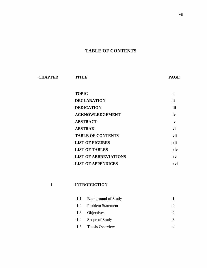
TABLE OF CONTENTS
CHAPTER TITLE PAGE
TOPIC i
DECLARATION ii
DEDICATION iii
ACKNOWLEDGEMENT iv
ABSTRACT v
ABSTRAK vi
TABLE OF CONTENTS vii
LIST OF FIGURES xii
LIST OF TABLES xiv
LIST OF ABBREVIATIONS xv
LIST OF APPENDICES xvi
1 INTRODUCTION
1.1 Background of Study 1
1.2 Problem Statement 2
1.3 Objectives 2
1.4 Scope of Study 3
1.5 Thesis Overview 4
viii
2 LITERATURE REVIEW
2.1 Introduction 6
2.2 Review of current project 7
2.2.1 Shadow Tracker® Expert 7
2.2.2 CarChip Pro Automotive Data Logger 8
2.3 Review of project module 9
2.3.1 PIC18F452 Microchip Controller 10
2.3.2 Global Positioning System ( GPS ) 10
2.3.2.1 GPS Technology Brief 11
2.3.2.2 GPS Electronic Connections 14
2.3.2.3 GPS Status Indicators 15
2.3.2.4 GPS Mode Selection 16
2.3.2.5 GPS Electrical Characteristics 16
2.3.3 SanDisk MultiMediaCard and Reduced
-Size MultiMediaCard 17
2.3.3.1 Introduction 17
2.3.3.2 MMC Features 18
2.3.3.3 MMC Functional Description 19
2.3.3.4 Flash-Independent Technology 19
2.3.4 LCD module 20
2.3.5 GSM Module 20
2.3.5.1 Introduction 20
2.3.5.2 GSM Interface Description 21
2.3.5.3 GSM Operating Modes 22
2.3.5.4 GSM RS-232 Interface 23
2.3.5.5 SIM Interface 24
ix
2.3.5.6 Mechanical Characteristics and
Mounting 25
3 ELECTRONIC OVERVIEW
3.1 Microcontroller Unit ( MCU ) 26
3.1.1 Key features of the microcontroller 26
3.1.2 MCU Block Diagram 28
3.1.3 MCU Pin Diagram 29
3.1.4 Memory Organization 30
3.2 Module Interface 31
3.2.1 Serial Communication Interface ( SCI ) 31
3.2.1.1 Serial Communication Interface
( SCI ) between MCU and GPS
module 32
3.2.1.2 Serial Communication Interface
( SCI ) between MCU and GSM
Module 32
3.2.2 Serial Peripheral Interface ( SPI ) 32
3.2.3 Parallel I/O Interface 34
3.3 Voltage Regulator 34
4 SOFTWARE OVERVIEW
4.1 Introduction 36
4.2 PIC C Compiler Software 37
x
4.3 Proteus 7 Professional Simulator 38
4.4 Mini GPS 40
4.5 PIC Kit 2 Programmer 41
5 SMART VEHICLE DATA LOGGER SYSTEM
5.1 Introduction 43
5.2 Hardware setup 43
5.2.1 Microcontroller Setup 46
5.2.2 GPS receiver setup 47
5.2.3 GSM Modem setup 48
5.2.4 Multimedia card setup 49
5.2.5 LCD Module setup 50
5.3 Software setup 50
5.3.1 GPS receiver source code 51
5.3.2 GSM Modem source code 52
5.3.3 MMC source code 53
6 RESULT AND ANALYSIS
6.1 Introduction 54
6.2 GPS Evaluation Board 54
6.2.1 Result from Hyper Terminal 56
6.2.2 GPS Data Analysis 56
6.3 Simulation connection of GPS, PIC 18F452
Microcontroller and LCD Module using ISIS 7
Professional Software. 59
6.3.1 Circuit Diagram 60
xi
6.3.2 Source Code for PIC18F452
Microcontroller / C Programming for
PIC18F452 60
6.3.3 Input From Virtual Memory in the
Simulation 61
6.3.4 Output shown from the circuit in the
ISIS 7 Pro software 62
6.4 Result on hardware development 65
7 CONCLUSION
7.1 Introduction 68
7.2 Future Recommendation 69
7.3 Costing and Commercialization 69
REFERENCES 70
APPENDICES 71
xii
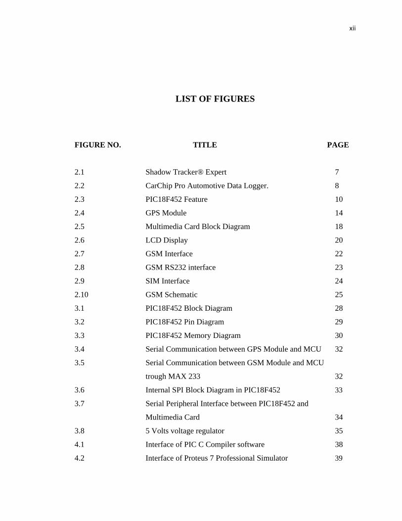
LIST OF FIGURES
FIGURE NO. TITLE PAGE 2.1 Shadow Tracker® Expert 7
2.2 CarChip Pro Automotive Data Logger. 8
2.3 PIC18F452 Feature 10
2.4 GPS Module 14
2.5 Multimedia Card Block Diagram 18
2.6 LCD Display 20
2.7 GSM Interface 22
2.8 GSM RS232 interface 23
2.9 SIM Interface 24
2.10 GSM Schematic 25
3.1 PIC18F452 Block Diagram 28
3.2 PIC18F452 Pin Diagram 29
3.3 PIC18F452 Memory Diagram 30
3.4 Serial Communication between GPS Module and MCU 32
3.5 Serial Communication between GSM Module and MCU
trough MAX 233 32
3.6 Internal SPI Block Diagram in PIC18F452 33
3.7 Serial Peripheral Interface between PIC18F452 and
Multimedia Card 34
3.8 5 Volts voltage regulator 35
4.1 Interface of PIC C Compiler software 38
4.2 Interface of Proteus 7 Professional Simulator 39
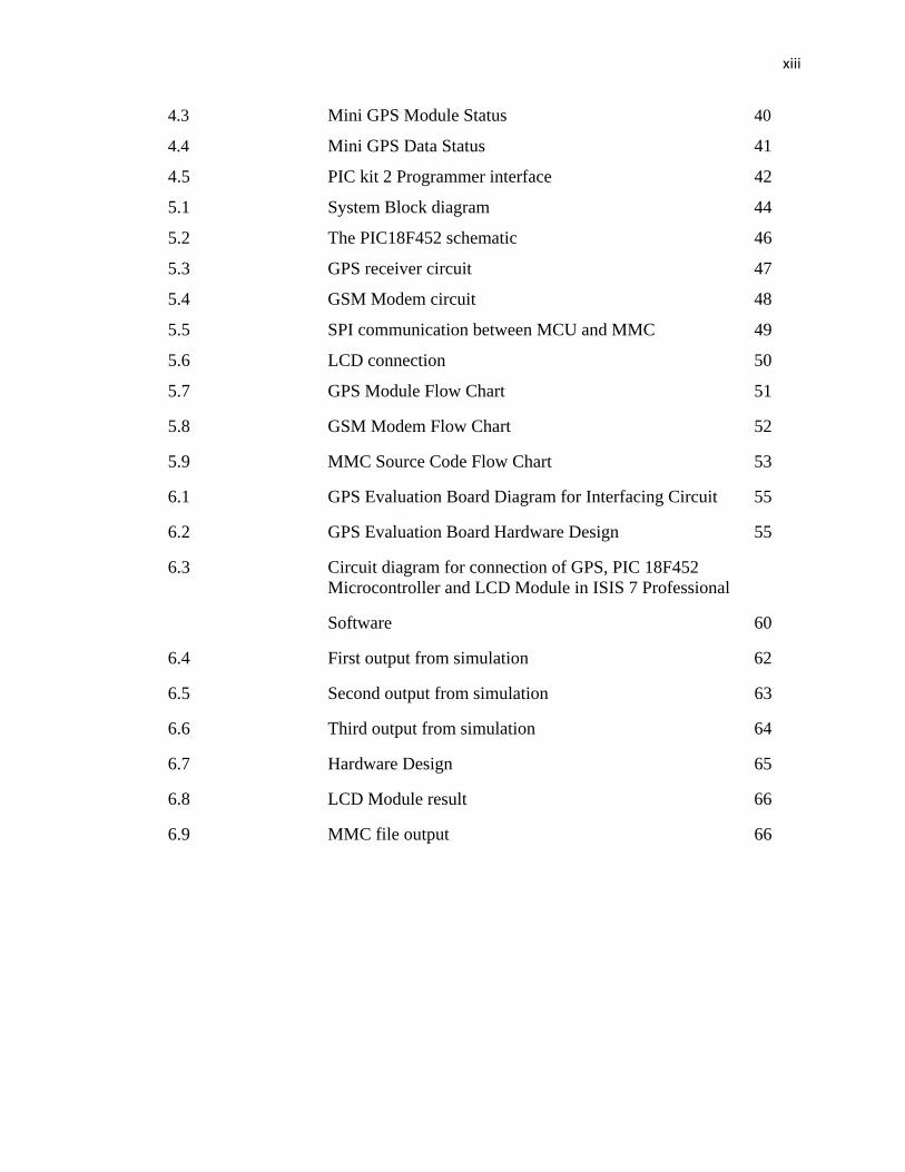
xiii
4.3 Mini GPS Module Status 40
4.4 Mini GPS Data Status 41
4.5 PIC kit 2 Programmer interface 42
5.1 System Block diagram 44
5.2 The PIC18F452 schematic 46
5.3 GPS receiver circuit 47
5.4 GSM Modem circuit 48
5.5 SPI communication between MCU and MMC 49
5.6 LCD connection 50
5.7 GPS Module Flow Chart 51
5.8 GSM Modem Flow Chart 52
5.9 MMC Source Code Flow Chart 53
6.1 GPS Evaluation Board Diagram for Interfacing Circuit 55
6.2 GPS Evaluation Board Hardware Design 55
6.3 Circuit diagram for connection of GPS, PIC 18F452 Microcontroller and LCD Module in ISIS 7 Professional
Software 60
6.4 First output from simulation 62
6.5 Second output from simulation 63
6.6 Third output from simulation 64
6.7 Hardware Design 65
6.8 LCD Module result 66
6.9 MMC file output 66
xiv
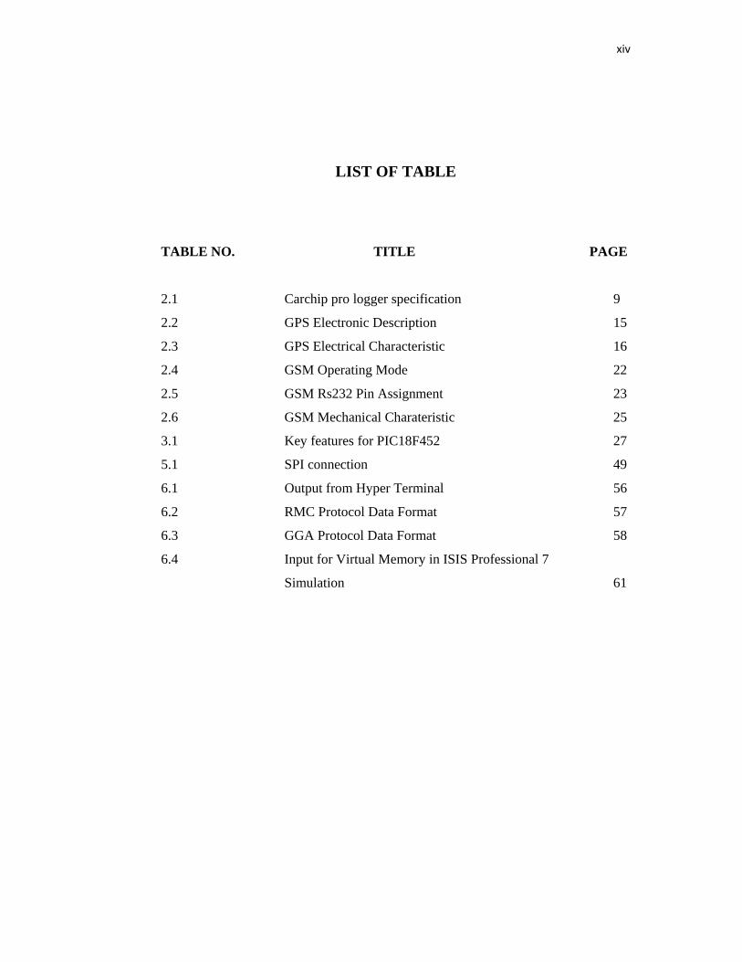
LIST OF TABLE
TABLE NO. TITLE PAGE 2.1 Carchip pro logger specification 9
2.2 GPS Electronic Description 15
2.3 GPS Electrical Characteristic 16
2.4 GSM Operating Mode 22
2.5 GSM Rs232 Pin Assignment 23
2.6 GSM Mechanical Charateristic 25
3.1 Key features for PIC18F452 27
5.1 SPI connection 49
6.1 Output from Hyper Terminal 56
6.2 RMC Protocol Data Format 57
6.3 GGA Protocol Data Format 58
6.4 Input for Virtual Memory in ISIS Professional 7
Simulation 61
xv
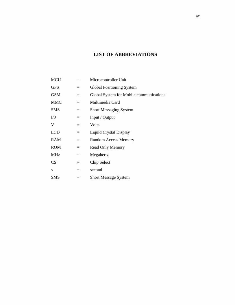
LIST OF ABBREVIATIONS
MCU = Microcontroller Unit
GPS = Global Positioning System
GSM = Global System for Mobile communications
MMC = Multimedia Card
SMS = Short Messaging System
I/0 = Input / Output
V = Volts
LCD = Liquid Crystal Display
RAM = Random Access Memory
ROM = Read Only Memory
MHz = Megahertz
CS = Chip Select
s = second
SMS = Short Message System
xvi
LIST OF APPENDICES
APPENDIX TITLE PAGE
A MICRO CONTROLLER SOURCE CODE 71
B PIC 18F452 DATASHEET 77
C GPS PROTOCOL 84
D SANDISK MULTIMEDIA CARD USER MANUAL 92
E MAX 233 DATASHEET 98
CHAPTER 1
INTRODUCTION
1.1 Project Overview
Nowadays, there are lots of technologies growing in this world. Technologies
such as Global Positioning System (GPS), Global System for Mobile
communications (GSM) and Multimedia card (MMC) make our lives more
comfortable.
Global Positioning System (GPS): A typical GPS receiver calculates its
position using the signals from four or more GPS satellites. Four satellites are needed
since the process needs a very accurate local time, more accurate than any normal
clock can provide, so the receiver internally solves for time as well as position. In
other words, the receiver uses four measurements to solve for 4 variables - x, y, z,
and t. These values are then turned into more user-friendly forms, such as
latitude/longitude or location on a map, then displayed to the user.
Global System for Mobile communications (GSM) is the most popular
standard for mobile phones in the world. GSM is used by over 2 billion people across
more than 212 countries and territories. Its ubiquity makes international roaming
very common between mobile phone operators, enabling subscribers to use their
phones in many parts of the world.
2
The MultiMediaCard (MMC) is a flash memory card standard. MMC is
used as storage media for a portable device, in a form that can easily be removed for
access by a PC. For example, a digital camera would use an MMC for storing image
files. With an MMC reader (typically a small box that connects via USB or some
other serial connection, although some can be found integrated into the computer
itself), a user could copy the pictures taken with the digital camera off to his or her
computer. MMCs are currently available in sizes up to and including 4 GB with
8 GB models announced but not yet available.
As we all know, there are lots of car that produced by local company, but,
customer cannot detect the vehicle’s location. Customers also cannot log the history
of the vehicle travel. So, a product had been design which uses all these technologies
in order to make costumer more comfortable with the car.
1.2 Problem statement
As we all know, there are lots of vehicles that produced by local company.
But, there are something not available yet:
1. Owners cannot trace their vehicle’s location.
2. Owners also cannot log the history of the vehicle travel.
In order to these problem, a vehicle data logger will be design which can log
the history of the vehicle travel and trace the vehicle’s location.
1.3 Project Objective
The main objective of this project is to design a data logger that has ability to
log data of a vehicle. There are three others objectives to be achieved beside the main
objective stated above. The three objectives are discussed in the following paragraph.
3
First of all, design a controller that can read the data from GPS receiver and
analysis the data till get the certain protocol only. The protocol that had been
analyzed will show the time , longitude, latitude, date and speed of the receiver. To
show all the data is valid or not, the four characteristics will be display to user.
The second objective is to store all the data that had been analyzed into a
suitable storage. The storage must be large capacity because the data from GPS
always receive at every second.
Last but not lease, to make the system is more friendly user , there will be a
controller that can make two way communication between user and the system. With
this system, user can track the vehicle either send a SMS or make a phone call to the
system.
1.4 Project Scope Few scopes and guidelines are listed to ensure the project is conducted within
its intended boundary. This is to ensure the project is heading to the right direction to
achieve its intended objectives.
The first scope is to design a controller that can control all the works in the
system. The controller can read the GPS data, store the data into a storage card,
display it at LCD and do transmit / receive to GSM module. In the other hand, the
controller is the brain of the system.
Second scope of this project is to analysis the data from GPS receiver which
can get the time , longitude, latitude, date and speed of the receiver. The data will be
display at LCD Display.
4
The third scope is to store the data from GPS receiver into a Multimedia
Card. All the time , longitude, latitude, date and speed of the GPS receiver will be
store into MMC card through the microcontroller.
The last scope of this project is to trace the location of the vehicle using
Global System for Mobile communications (GSM) (two way communication between
user and GSM Module) and Global Positioning System (GPS).
1.5 Thesis Overview
This thesis consist of seven chapters. The first chapter will give an overview
of the project as well as the objective of the project.
Chapter 2 covers the literature review or discuss about the research of the
data logger current project and the component that will be used for this project. From
this chapter, we can know all the protocol and characteristic of GPS Receiver, GPS
Modem and MMC Configuration system.
Chapter 3 covers the electronic overview of the project. It describes the
various modules developed, basic operation of each module. All five module are
describe briefly in this chapter.
The elaboration of the software development will be discuss in Chapter 4. All
the software used for this project will be describe briefly in this chapter.
The system implementation of the project will be discuss on Chapter 5. In
this chapter, the software and hardware combination will be explained briefly. The
hardware will be elaborates from the circuits and the programming of each modules
will be discussed by using flow charts.

5
Chapter 6 explains the testing and result of each module. The result system
effectiveness is also discussed.
Chapter 7 summarized the project outcome. A few suggestions are proposed
to enhance the current design.
CHAPTER 2
LITERATURE REVIEW 2.1 Introduction In this chapter, we will discuss about the research of the data logger current
project and the component that will be used for this project. From this literature
review, we can get the idea of the function and description of the modules such as
GPS module, GSM module and Multimedia card system.
This chapter is divided by two sections. One section is for current project and
the another section is about the research of module use in this project. The sub
section are listed as below :
i. Current Project
• Shadow Tracker® Expert
• CarChip Pro Automotive Data Logger
ii. Module research.
• PIC18F452 Microchip Controller
• Global Positioning System ( GPS )
• SanDisk MultiMediaCard and Reduced-Size MultiMediaCard
• LCD module
• GSM Module
2
t
o
2
e
S
r
F
2.2 Revi
In th
that related
order to log
i. S
ii. C
2.2.1 Shad
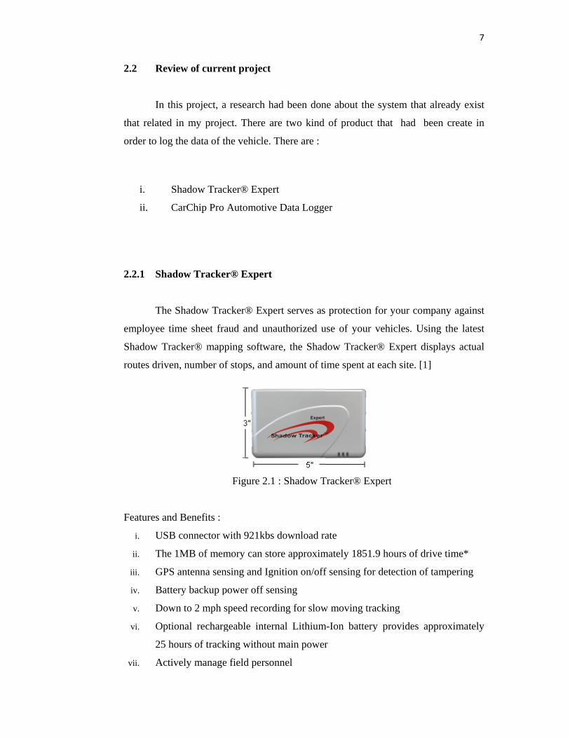
The
employee tim
Shadow Tra
routes driven
Features and
i. USB
ii. The
iii. GPS
iv. Batte
v. Dow
vi. Optio
25 ho
vii. Activ
iew of curre
his project, a
in my proje
the data of t
Shadow Trac
CarChip Pro
dow Tracke
Shadow Tra
me sheet fra
acker® mapp
n, number of
d Benefits :
B connector w
1MB of mem
antenna sen
ery backup p
wn to 2 mph s
onal recharg
ours of track
vely manage
ent project
a research ha
ect. There ar
the vehicle. T
cker® Exper
Automotive
er® Expert
acker® Expe
aud and una
ping softwar
f stops, and
Figure 2.1
with 921kbs
mory can sto
nsing and Ign
power off sen
speed record
geable intern
king without
e field person
ad been don
re two kind
There are :
rt
e Data Logge
ert serves as
authorized u
re, the Shad
amount of ti
: Shadow T
download ra
ore approxim
nition on/off
nsing
ding for slow
nal Lithium
t main power
nnel
ne about the
of product
er
protection f
use of your v
dow Tracker
ime spent at
Tracker® Exp
ate
mately 1851.
f sensing for
w moving tra
m-Ion battery
r
system that
that had b
for your com
vehicles. Us
r® Expert d
each site. [1
pert
9 hours of d
r detection of
acking
y provides a
t already exi
been create
mpany again
sing the late
displays actu
1]
drive time*
f tampering
approximate
7
ist
in
nst
est
ual
ely
8
viii. Know where your mobile workforce is every day
ix. Prevent incidents of employee time sheet fraud
x. Cut mobile fleet costs
xi. Head off customer service complaints
* Based on a 120 second collection rate of actual drive time
According to this product, it do not have two way communication using GSM.
So, owner cannot trace the car on time.
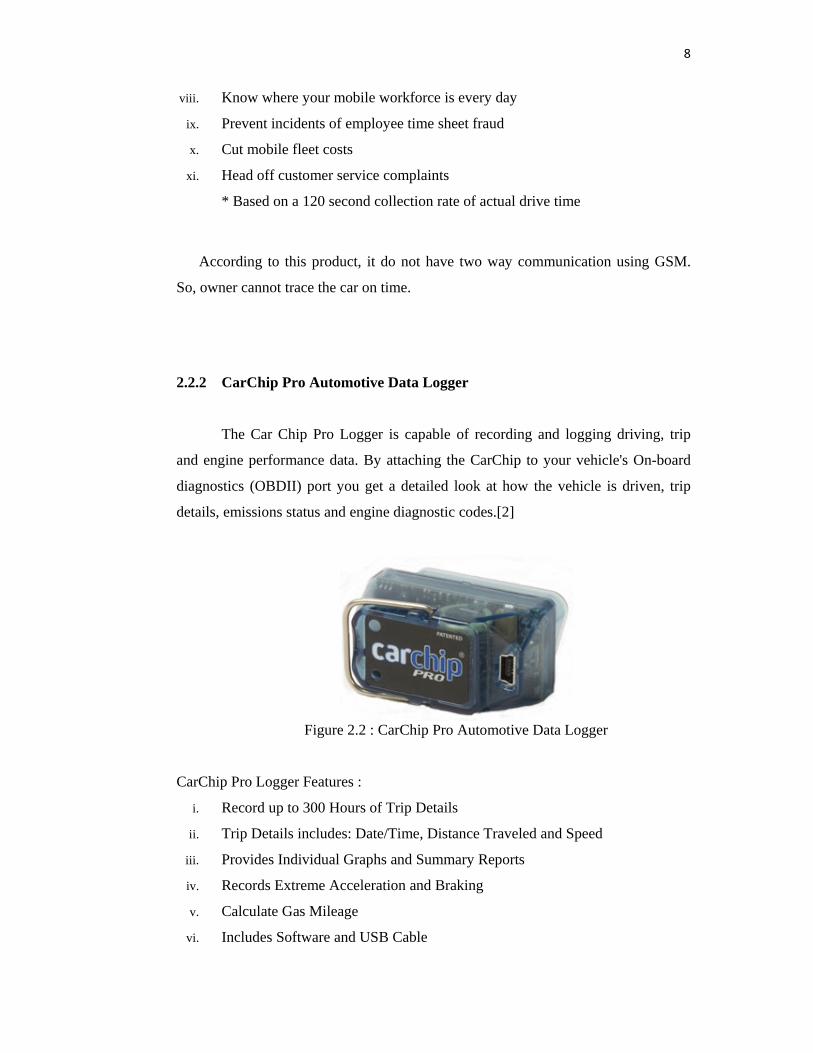
2.2.2 CarChip Pro Automotive Data Logger The Car Chip Pro Logger is capable of recording and logging driving, trip
and engine performance data. By attaching the CarChip to your vehicle's On-board
diagnostics (OBDII) port you get a detailed look at how the vehicle is driven, trip
details, emissions status and engine diagnostic codes.[2]
Figure 2.2 : CarChip Pro Automotive Data Logger
CarChip Pro Logger Features :
i. Record up to 300 Hours of Trip Details
ii. Trip Details includes: Date/Time, Distance Traveled and Speed
iii. Provides Individual Graphs and Summary Reports
iv. Records Extreme Acceleration and Braking
v. Calculate Gas Mileage
vi. Includes Software and USB Cable
9
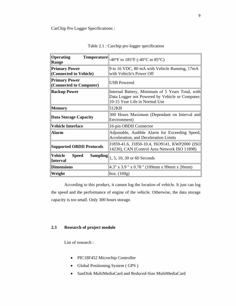
CarChip Pro Logger Specifications :
Table 2.1 : Carchip pro logger specification
Operating Temperature Range -40°F to 185°F (-40°C to 85°C)
Primary Power (Connected to Vehicle)
9 to 16 VDC, 80 mA with Vehicle Running, 17mA with Vehicle's Power Off
Primary Power (Connected to Computer) USB Powered
Backup Power Internal Battery, Minimum of 5 Years Total, with Data Logger not Powered by Vehicle or Computer; 10-15 Year Life in Normal Use
Memory 512KB
Data Storage Capacity 300 Hours Maximum (Dependant on Interval and Environment)
Vehicle Interface 16-pin OBDII Connector Alarm Adjustable, Audible Alarm for Exceeding Speed,
Acceleration, and Deceleration Limits
Supported OBDII Protocols J1859-41.6, J1850-10.4, ISO9141, KWP2000 (ISO 14230), CAN (Control Area Network ISO 11898)
Vehicle Speed Sampling Interval 1, 5, 10, 30 or 60 Seconds
Dimensions 4.3" x 3.9 " x 0.78 " (109mm x 99mm x 20mm) Weight 6oz. (169g) According to this product, it cannot log the location of vehicle. It just can log
the speed and the performance of engine of the vehicle. Otherwise, the data storage
capacity is too small. Only 300 hours storage.
2.3 Research of project module List of research :
• PIC18F452 Microchip Controller
• Global Positioning System ( GPS )
• SanDisk MultiMediaCard and Reduced-Size MultiMediaCard
10
• LCD module
• GSM Module
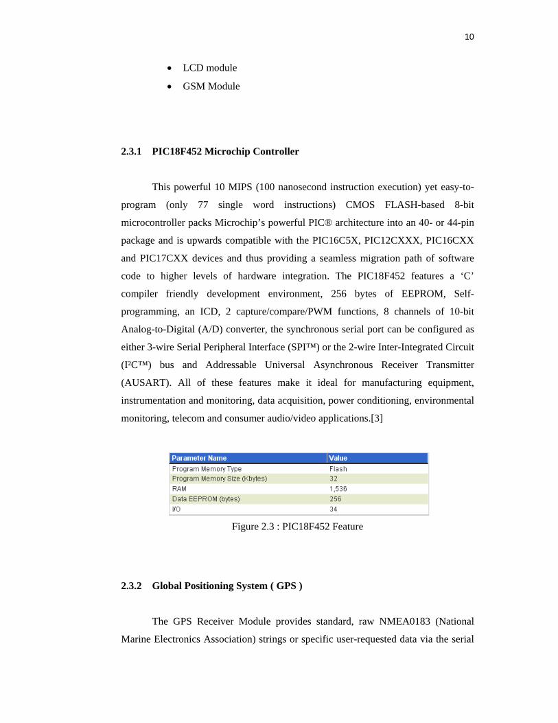
2.3.1 PIC18F452 Microchip Controller This powerful 10 MIPS (100 nanosecond instruction execution) yet easy-to-
program (only 77 single word instructions) CMOS FLASH-based 8-bit
microcontroller packs Microchip’s powerful PIC® architecture into an 40- or 44-pin
package and is upwards compatible with the PIC16C5X, PIC12CXXX, PIC16CXX
and PIC17CXX devices and thus providing a seamless migration path of software
code to higher levels of hardware integration. The PIC18F452 features a ‘C’
compiler friendly development environment, 256 bytes of EEPROM, Self-
programming, an ICD, 2 capture/compare/PWM functions, 8 channels of 10-bit
Analog-to-Digital (A/D) converter, the synchronous serial port can be configured as
either 3-wire Serial Peripheral Interface (SPI™) or the 2-wire Inter-Integrated Circuit
(I²C™) bus and Addressable Universal Asynchronous Receiver Transmitter
(AUSART). All of these features make it ideal for manufacturing equipment,
instrumentation and monitoring, data acquisition, power conditioning, environmental
monitoring, telecom and consumer audio/video applications.[3]
Figure 2.3 : PIC18F452 Feature
2.3.2 Global Positioning System ( GPS )
The GPS Receiver Module provides standard, raw NMEA0183 (National
Marine Electronics Association) strings or specific user-requested data via the serial
11
command interface, tracking of up to 12 satellites, and WAAS/EGNOS (Wide Area
Augmentation System/European Geostationary Navigation Overlay Service)
functionality for more accurate positioning results.
The Module provides current time, date, latitude, longitude, altitude, speed,
and travel direction/heading, among other data, and can be used in a wide variety of
hobbyist and commercial applications, including navigation, tracking systems,
mapping, fleet management, auto-pilot, and robotics. [4]
2.3.2.1 GPS Technology Brief
GPS (Global Positioning System) is a worldwide radio-navigation system
formed by a constellation of 24 satellites and their ground stations. With an
unobstructed, clear view of the sky, GPS works anywhere in the world, 24 hours a
day, seven days a week.
The Global Positioning System consists of three interacting components:
1) The Space Segment -- satellites orbiting the earth.
2) The Control Segment -- the control and monitoring stations run by the United
States Department of Defense (not discussed in this documentation).
3) The User Segment -- the GPS signal receivers owned by civilians and military.
The space segment consists of a constellation of 24 active satellites (and one
or more in-orbit spares) orbiting the earth every 12 hours. Four satellites are located
in each of six orbits and will be visible from any location on each 95 percent of the
time. The orbits are distributed evenly around the earth, and are inclined 55 degrees
from the equator. The satellites orbit at an altitude of about 11,000 nautical miles.
Each satellite transmits two signals: L1 (1575.42 MHz) and L2 (1227.60
MHz). The L1 signal is modulated with two pseudo-random noise signals - the
protected (P) code, and the course/acquisition (C/A) code. The L2 signal only carries
12
the P code. Civilian navigation receivers only use the C/A code on the L1 frequency.
Each signal from each satellite contains a repeating message, indicating the position
and orbital parameters of itself and the other satellites (almanac), a bill of health for
the satellites (health bit), and the precise atomic time.
The receiver measures the time required for the signal to travel from the
satellite to the receiver, by knowing the time that the signal left the satellite, and
observing the time it receives the signal, based on its internal clock. If the receiver
had a perfect clock, exactly in sync with those on the satellites, three measurements,
from three satellites, would be sufficient to determine position in three dimensions
via triangulation. However, that is not the case, so a fourth satellite is needed to
resolve the receiver clock error. With four satellites, a GPS receiver can provide very
accurate clock (time, date) and position information (latitude, longitude, altitude,
speed, travel direction/heading).
Note that position data and accuracy are affected or degraded by the satellite
geometry, electromagnetic interference, and multipath, an unpredictable set of
reflections and/or direct waves each with its own degree of attenuation and delay.
Primarily due to satellite geometry, measuring altitude using GPS may introduce an
accuracy error of 1.5 times the receiver’s position accuracy (in the case of our GPS
Receiver Module, this corresponds to about +/-20 meters in the vertical direction).
GPS signals work in the microwave radio band. They can pass through glass,
but are absorbed by water molecules (wood, heavy foliage) and reflect off concrete,
steel, and rock. This means that GPS units have trouble operating in rain forests,
urban jungles, deep canyons, inside automobiles and boats, and in heavy snowfall -
among other things. These environmental obstacles degrade positional accuracy or
make it impossible to get a fix on your location.
Most GPS receivers output a stream of data so that it can be used and
interpreted by other devices. The most common format (and used by our GPS
Receiver Module in “Raw Mode”) is NMEA0183 (National Marine Electronics
13
Association, http://www.nmea.org/), developed for data communications between
marine instruments. Some receivers also have proprietary data formats which are
used (in the case of navigation receivers) to transfer waypoint lists, track logs, and
other data between the GPS and a computer. Such proprietary formats are not
covered by the NMEA standard.
The NMEA0183 is provided as a series of comma-delimited ASCII strings,
each preceded with an identifying header. The data is transmitted as a 4800bps string
of 8-bit ASCII characters. Thus, any microcontroller with a serial port can extract
data from a GPS module. But, modules do not produce "plain text" location
information. Instead, they create standardized "sentences," such as:
$GPGGA,170834,4124.8963,N,08151.6838,W,1,05,1.5,280.2,M,-34.0,M,,,*75
$GPGSA,A,3,19,28,14,18,27,22,31,39,,,,,1.7,1.0,1.3*34
$GPGSV,3,2,11,14,25,170,00,16,57,208,39,18,67,296,40,19,40,246,00*74
$GPRMC,220516,A,5133.82,N,00042.24,W,173.8,231.8,130694,004.2,W*70
Programmers can parse these strings to obtain their desired information,
including time, date, latitude, longitude, speed, and altitude.
There are three standard notations for displaying longitude and latitude data:
• GPS Coordinates (degrees, minutes, and fractional minutes), ex: 36 degrees, 35.9159 minutes
• DDMMSS (degrees, minutes, seconds), ex: 36 degrees, 35 minutes, 55.3
seconds
• Decimal Degrees, ex: 36.5986 degrees
In “Smart Mode,” the Parallax GPS Receiver Module transmits latitude and
longitude data to the user in GPS Coordinate format (degrees, minutes, and fractional
minutes, see the “Communication Protocol” section for more details). Conversion to
the two other notations, DDMMSS (degrees, minutes, second) and Decimal Degrees,
is trivial and demonstrated in the example code below.
14
To graphically display your GPS position using Google Maps (in map,
satellite, or hybrid view), simply go to http://maps.google.com/ and enter in your
decimal coordinates in the "Search" field (for example, "36.5986, -118.0599" without
the quotes).
To graphically display a track or series of waypoints, GPS Visualizer
(http://www.gpsvisualizer.com/) is a free, easy-to-use online utility that creates maps
and profiles from GPS data. GPS Visualizer can read data files from many different
sources, including raw NMEA strings (such as those captured directly from the
Parallax GPS Receiver Module in “Raw Mode”) or tab-delimited or comma-
separated text of relevant GPS data.
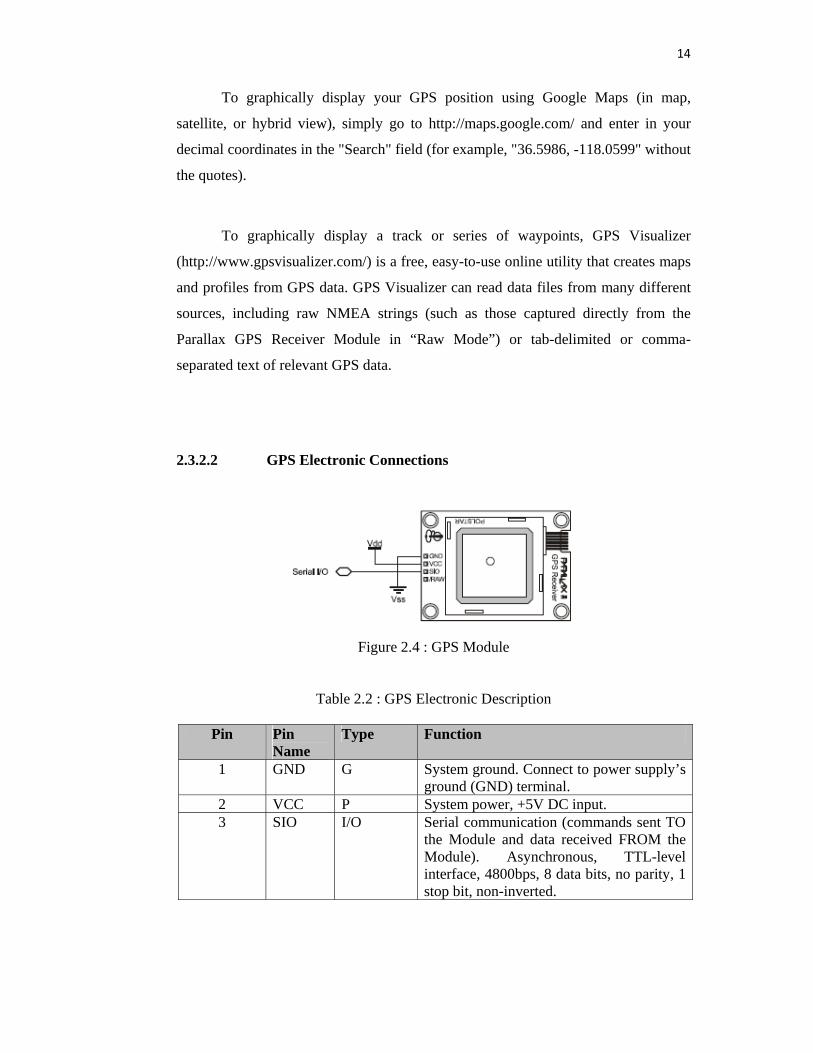
2.3.2.2 GPS Electronic Connections
Figure 2.4 : GPS Module
Table 2.2 : GPS Electronic Description
Pin Pin Name
Type Function
1 GND G System ground. Connect to power supply’s ground (GND) terminal.
2 VCC P System power, +5V DC input. 3 SIO I/O Serial communication (commands sent TO
the Module and data received FROM the Module). Asynchronous, TTL-level interface, 4800bps, 8 data bits, no parity, 1 stop bit, non-inverted.
15
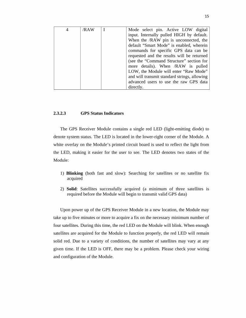
4 /RAW I Mode select pin. Active LOW digital input. Internally pulled HIGH by default. When the /RAW pin is unconnected, the default “Smart Mode” is enabled, wherein commands for specific GPS data can be requested and the results will be returned (see the “Command Structure” section for more details). When /RAW is pulled LOW, the Module will enter “Raw Mode” and will transmit standard strings, allowing advanced users to use the raw GPS data directly.
2.3.2.3 GPS Status Indicators
The GPS Receiver Module contains a single red LED (light-emitting diode) to
denote system status. The LED is located in the lower-right corner of the Module. A
white overlay on the Module’s printed circuit board is used to reflect the light from
the LED, making it easier for the user to see. The LED denotes two states of the
Module:
1) Blinking (both fast and slow): Searching for satellites or no satellite fix
acquired
2) Solid: Satellites successfully acquired (a minimum of three satellites is required before the Module will begin to transmit valid GPS data)
Upon power up of the GPS Receiver Module in a new location, the Module may
take up to five minutes or more to acquire a fix on the necessary minimum number of
four satellites. During this time, the red LED on the Module will blink. When enough
satellites are acquired for the Module to function properly, the red LED will remain
solid red. Due to a variety of conditions, the number of satellites may vary at any
given time. If the LED is OFF, there may be a problem. Please check your wiring
and configuration of the Module.
16
2.3.2.4 GPS Mode Selection
The /RAW pin allows user selection of the GPS Receiver Module’s two
operating modes:
• Smart Mode: When the /RAW pin is pulled HIGH or simply left unconnected
(the pin is internally pulled HIGH), the default “Smart Mode” is enabled,
wherein commands for specific GPS data can be requested and the results
will be returned. See the “Communication Protocol” section for more details.
• Raw Mode: When the /RAW pin is pulled LOW, “Raw Mode” is enabled in
which the Module will transmit standard NMEA0183 v2.2 strings (GGA,
GSV, GSA, and RMC), allowing advanced users to use the raw GPS data
directly. For more information on NMEA0183 data, see the “GPS
Technology Brief” section.
In either mode, data is transmitted at 4800bps, 8 data bits, no parity, 1 stop bit,
non-inverted, TTL-level.
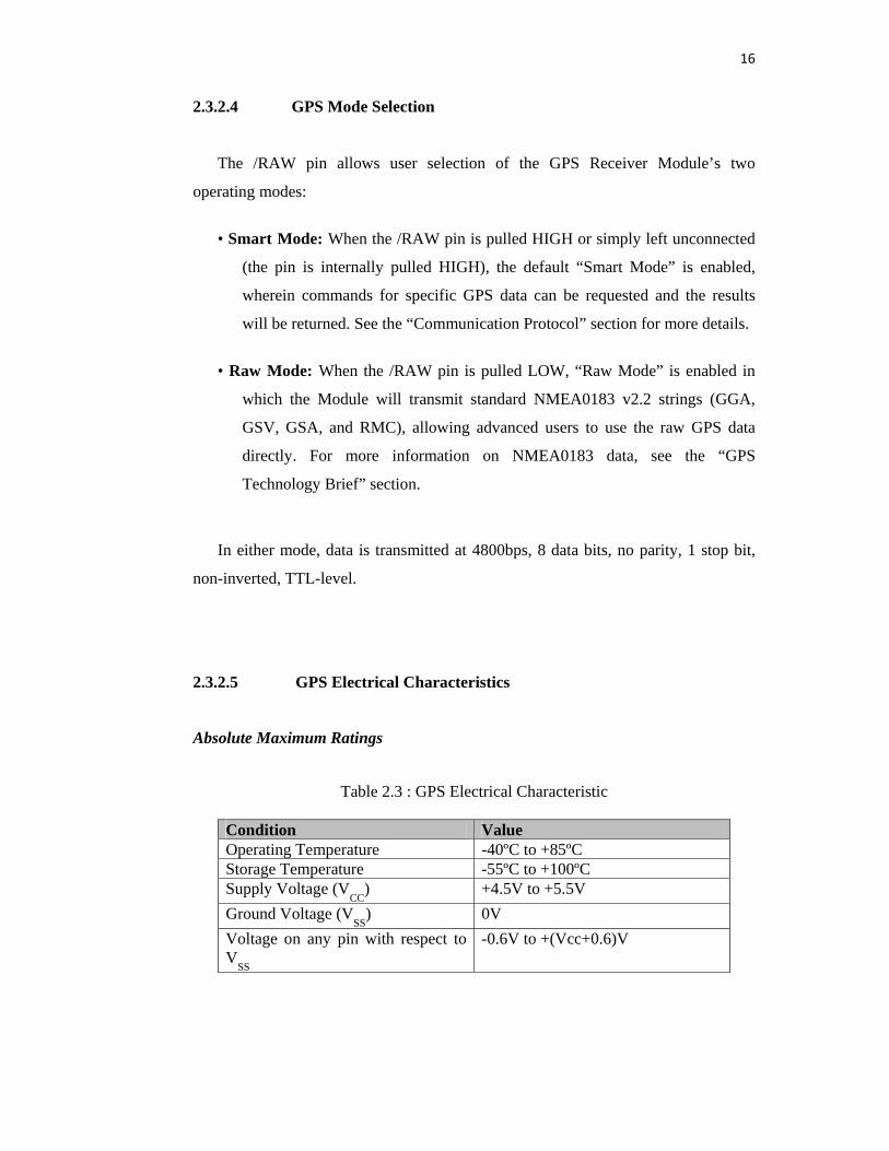
2.3.2.5 GPS Electrical Characteristics Absolute Maximum Ratings
Table 2.3 : GPS Electrical Characteristic
Condition Value Operating Temperature -40ºC to +85ºC Storage Temperature -55ºC to +100ºC Supply Voltage (V
CC) +4.5V to +5.5V
Ground Voltage (VSS
) 0V Voltage on any pin with respect to V
SS
-0.6V to +(Vcc+0.6)V
17
2.3.3 SanDisk MultiMediaCard and Reduced-Size MultiMediaCard 2.3.3.1 Introduction
The SanDisk MultiMediaCard and Reduced-Size MultiMediaCard (RS-
MMC) are very small, removable flash storage devices, designed specifically for
storage applications that put a premium on small form factor, low power and low
cost. Flash is the ideal storage medium for portable, battery-powered devices. It
features low power consumption and is non-volatile, requiring no power to maintain
the stored data. It also has a wide operating range for temperature, shock and
vibration.
The MultiMediaCard and RS-MultiMediaCard are well suited to meet the
needs of small, low power, electronic devices. With form factors of 32 mm x 24 mm
and 1.4 mm thick for the MultiMediaCard and 18 mm x 24 mm x1.4 mm for the RS-
MultiMediaCard, these cards can be used in a wide variety of portable devices like
mobile phones, and voicerecorders.
To support this wide range of applications, the MultiMediaCard Protocol, a
simple sevenpinserial interface, is designed for maximum scalability and
configurability. All device andinterface configuration data (such as maximum
frequency, card identification, etc.) are stored on the card.
The SanDisk MultiMediaCard/RS-MultiMediaCard interface allows for easy
integration into any design, regardless of microprocessor used. For compatibility
with existing controllers, the card offers, in addition to the card interface, an alternate
communication protocol, which is based on the Serial Peripheral Interface (SPI)
standard.
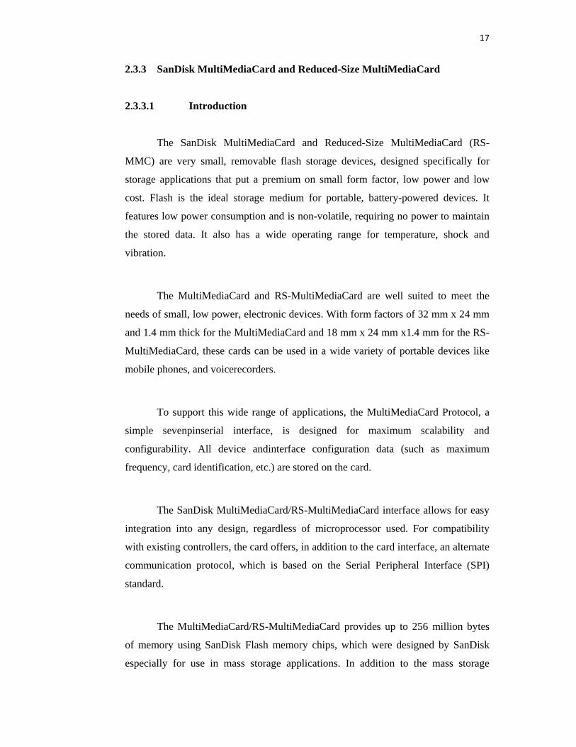
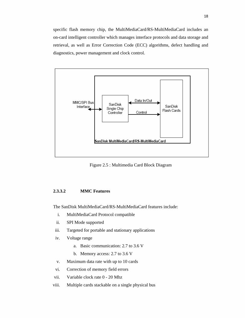
The MultiMediaCard/RS-MultiMediaCard provides up to 256 million bytes
of memory using SanDisk Flash memory chips, which were designed by SanDisk
especially for use in mass storage applications. In addition to the mass storage
18
specific flash memory chip, the MultiMediaCard/RS-MultiMediaCard includes an
on-card intelligent controller which manages interface protocols and data storage and
retrieval, as well as Error Correction Code (ECC) algorithms, defect handling and
diagnostics, power management and clock control.
Figure 2.5 : Multimedia Card Block Diagram 2.3.3.2 MMC Features The SanDisk MultiMediaCard/RS-MultiMediaCard features include:
i. MultiMediaCard Protocol compatible
ii. SPI Mode supported
iii. Targeted for portable and stationary applications
iv. Voltage range
a. Basic communication: 2.7 to 3.6 V
b. Memory access: 2.7 to 3.6 V
v. Maximum data rate with up to 10 cards
vi. Correction of memory field errors
vii. Variable clock rate 0 - 20 Mhz
viii. Multiple cards stackable on a single physical bus
19
2.3.3.3 MMC Functional Description
The MultiMediaCard and RS-MultiMediaCard contain a high level,
intelligent subsystem as shown by the block diagram in Figure 1-1. This intelligent
(microprocessor) subsystem provides many capabilities not found in other types of
memory cards. These capabilities include:
• Host independence from details of erasing and programming flash memory
• Sophisticated system for managing defects (analogous to systems found in
magnetic
disk drives)
• Sophisticated system for error recovery including a powerful error correction code
• Power management for low power operation
2.3.3.4 Flash-Independent Technology
The 512-byte sector size of the MultiMediaCard and RS-MultiMediaCard is
the same as that in an IDE magnetic disk drive. To write or read a sector (or multiple
sectors), the host computer software simply issues a read or write command to the
card. This command contains the address. The host software then waits for the
command to complete. The host software does not get involved in the details of how
the flash memory is erased, programmed or read. This is extremely important as flash
devices are expected to get more and more complex in the future. Because the
MultiMediaCard and RS-MultiMediaCard uses an intelligent on-board controller, the
host system software will not require changing as new flash memory evolves. In
other words, systems that support the SanDisk MultiMediaCard/RS-MultiMediaCard
today will be able to access future cards built with new flash technology without
having to update or change host software.
20
2.3.4 LCD module Liquid crystal display ( LCD ) is another common output device. There are
various type and model of LCD available in market. The type of JHD 162A LCD
will be used in this project. The role of LCD here will display the user information
such as username, time and date.
Some features of LCD are:
• 16 character x 2 row
• 7 x 5 dots
• Reflective with EL and LED backlight
• LED/4.2 VDC
LCD is divided into two register bits which are Control Register and Data
Register. The Control Register is used to control the operation of LCD while the data
register is used to display the character. The figure 2.6 show the LCD display device.
Figure 2.6 : LCD Display
2.3.5 GSM Module 2.3.5.1 Introduction
This part describes the hardware of TMAS GSM/GPRS Terminal. The
information is intended for users or developers who design and build wireless
cellular, M2M or other data telemetry applications. The scope of this part includes
21
interface specifications, mechanical characteristics of TMAS GSM/GPRS Terminal
and power supply issues. TMAS GSM/GPRS Terminal is a compact GSM modem
terminal for the transfer of data, SMS and faxes in the GSM networks.
Cinterion/Siemens MC52i/MC55i/MC39i/TC35i GSM engine is embedded to
provide good quality and reliability of data transfer. Terminal design is also based
the industrial standard interfaces and an integrated SIM card reader to allow ease of
use to the users.[6]
Module benefit :
i. Low cost
ii. CE Certified, Reliable and Quality with approved GSM/GPRS
modules from Cinterion (a.k.a. Siemens)
iii. Non Proprietary Accessories, i.e. standard power adapter and standard
modem cable
iv. (You can have the option to purchase these standard accessories in
your country or from TCAM or from any cheaper source)
v. Compact and nice stylish silver casing
vi. Flexible mounting: Rail fixing or side mounting plates.
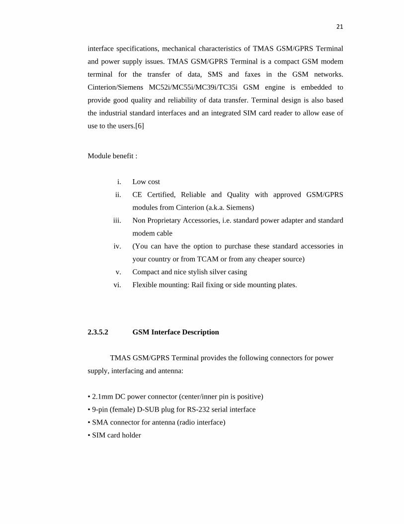
2.3.5.2 GSM Interface Description
TMAS GSM/GPRS Terminal provides the following connectors for power
supply, interfacing and antenna:
• 2.1mm DC power connector (center/inner pin is positive)
• 9-pin (female) D-SUB plug for RS-232 serial interface
• SMA connector for antenna (radio interface)
• SIM card holder
22
Figure 2.7: GSM Interface
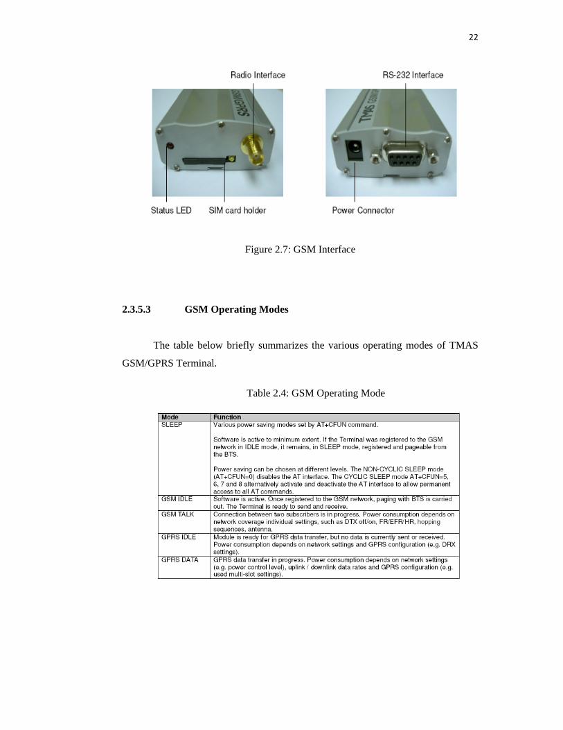
2.3.5.3 GSM Operating Modes
The table below briefly summarizes the various operating modes of TMAS
GSM/GPRS Terminal.
Table 2.4: GSM Operating Mode
23
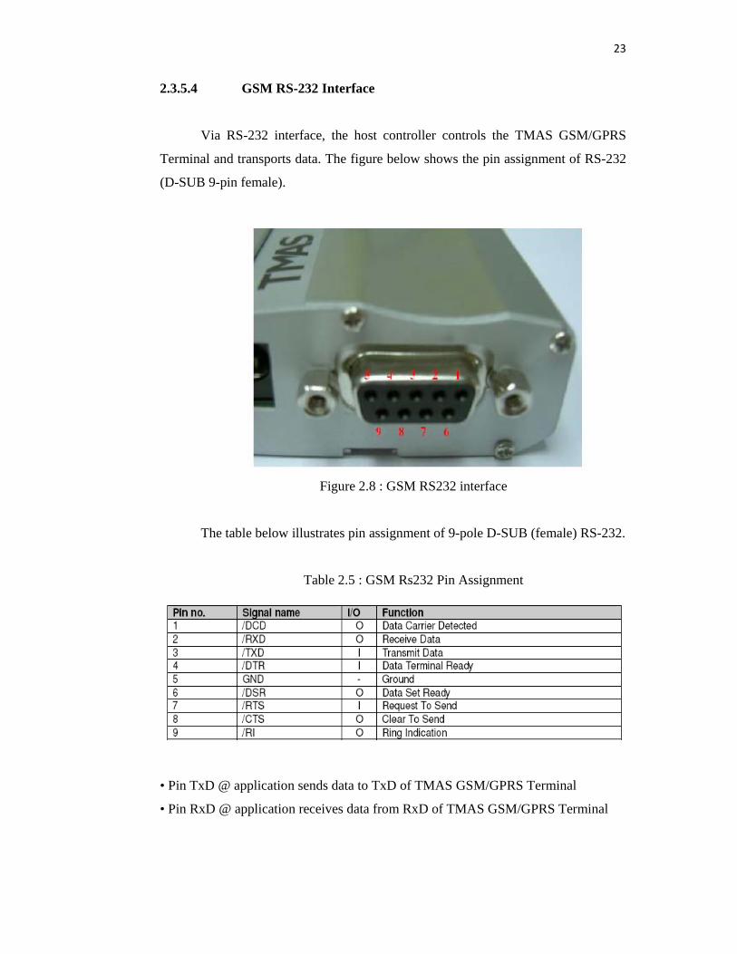
2.3.5.4 GSM RS-232 Interface
Via RS-232 interface, the host controller controls the TMAS GSM/GPRS
Terminal and transports data. The figure below shows the pin assignment of RS-232
(D-SUB 9-pin female).
Figure 2.8 : GSM RS232 interface
The table below illustrates pin assignment of 9-pole D-SUB (female) RS-232.
Table 2.5 : GSM Rs232 Pin Assignment
• Pin TxD @ application sends data to TxD of TMAS GSM/GPRS Terminal
• Pin RxD @ application receives data from RxD of TMAS GSM/GPRS Terminal
24
The RS-232 interface is implemented as a serial asynchronous transmitter and
receiver conforming to ITU-T V.24 Interchange Circuits DCE. It is configured for 8
data bits, no parity and 1 stop bit, and can be operated at bit rates from 300bps to
115Kbps. Autobauding supports bit rates from 4.8Kbps to 115Kbps. Hardware
handshake using the /RTS and /CTS signals and XON/XOFF software flow control
are supported. In addition, the modem control signals /DTR, /DSR, /DCD and /RING
are available. The modem control signal RING (Ring Indication) can be used to
indicate to the cellular device application, that a call or Unsolicited Result Code
(URC) is received. There are different modes of operation, which can be set with AT
commands.
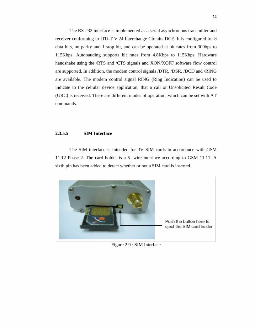
2.3.5.5 SIM Interface
The SIM interface is intended for 3V SIM cards in accordance with GSM
11.12 Phase 2. The card holder is a 5- wire interface according to GSM 11.11. A
sixth pin has been added to detect whether or not a SIM card is inserted.
Figure 2.9 : SIM Interface