Embed Size (px)
Citation preview
Benchmark Example No. 6
Warping Torsion Bar
SOFiSTiK | 2020
VERiFiCATiONBE6 Warping Torsion Bar
VERiFiCATiON Manual, Service Pack 2020-4 Build 54
Copyright © 2020 by SOFiSTiK AG, Oberschleissheim, Germany.
SOFiSTiK AG
HQ Oberschleissheim Office Nuremberg
Bruckmannring 38 Flataustraße 14
85764 Oberschleissheim 90411 Nuremberg
Germany Germany
T +49 (0)89 315878-0 T +49 (0)911 39901-0
F +49 (0)89 315878-23 F +49(0)911 397904
This manual is protected by copyright laws. No part of it may be translated, copied or reproduced, in any form or byany means, without written permission from SOFiSTiK AG. SOFiSTiK reserves the right to modify or to release
new editions of this manual.
The manual and the program have been thoroughly checked for errors. However, SOFiSTiK does not claim thateither one is completely error free. Errors and omissions are corrected as soon as they are detected.
The user of the program is solely responsible for the applications. We strongly encourage the user to test thecorrectness of all calculations at least by random sampling.
Front Cover
Project: Queensferry Crossing | Photo: Bastian Kratzke
Warping Torsion Bar
Overview
Element Type(s): B3D
Analysis Type(s): STAT
Procedure(s):
Topic(s):
Module(s): ASE
Input file(s): warping.dat
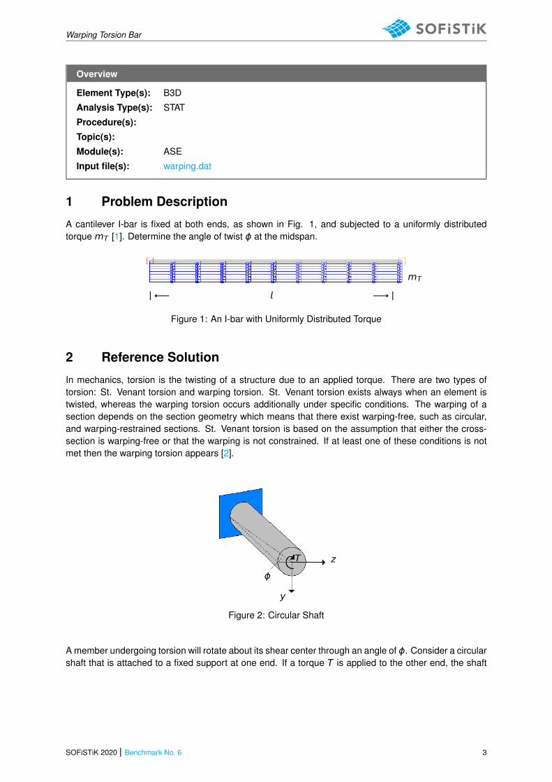
1 Problem Description
A cantilever I-bar is fixed at both ends, as shown in Fig. 1, and subjected to a uniformly distributedtorque mT [1]. Determine the angle of twist ϕ at the midspan.
| ←− −→ |
mT
Figure 1: An I-bar with Uniformly Distributed Torque
2 Reference Solution
In mechanics, torsion is the twisting of a structure due to an applied torque. There are two types oftorsion: St. Venant torsion and warping torsion. St. Venant torsion exists always when an element istwisted, whereas the warping torsion occurs additionally under specific conditions. The warping of asection depends on the section geometry which means that there exist warping-free, such as circular,and warping-restrained sections. St. Venant torsion is based on the assumption that either the cross-section is warping-free or that the warping is not constrained. If at least one of these conditions is notmet then the warping torsion appears [2].
y
z
ϕ
T
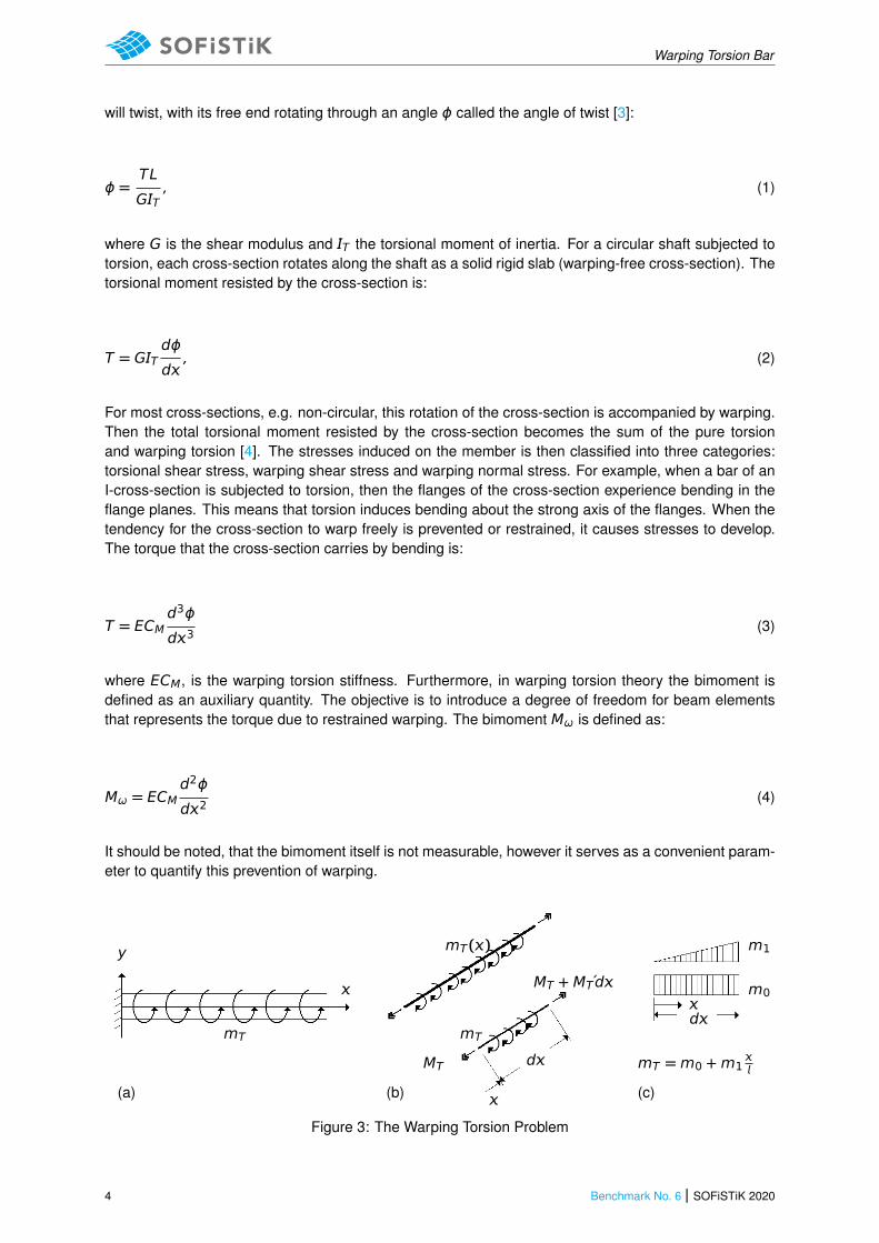
Figure 2: Circular Shaft
A member undergoing torsion will rotate about its shear center through an angle of ϕ. Consider a circularshaft that is attached to a fixed support at one end. If a torque T is applied to the other end, the shaft
SOFiSTiK 2020 | Benchmark No. 6 3
Warping Torsion Bar
will twist, with its free end rotating through an angle ϕ called the angle of twist [3]:
ϕ =TL
GT, (1)
where G is the shear modulus and T the torsional moment of inertia. For a circular shaft subjected totorsion, each cross-section rotates along the shaft as a solid rigid slab (warping-free cross-section). Thetorsional moment resisted by the cross-section is:
T = GTdϕ
d, (2)
For most cross-sections, e.g. non-circular, this rotation of the cross-section is accompanied by warping.Then the total torsional moment resisted by the cross-section becomes the sum of the pure torsionand warping torsion [4]. The stresses induced on the member is then classified into three categories:torsional shear stress, warping shear stress and warping normal stress. For example, when a bar of anI-cross-section is subjected to torsion, then the flanges of the cross-section experience bending in theflange planes. This means that torsion induces bending about the strong axis of the flanges. When thetendency for the cross-section to warp freely is prevented or restrained, it causes stresses to develop.The torque that the cross-section carries by bending is:
T = ECMd3ϕ
d3(3)
where ECM, is the warping torsion stiffness. Furthermore, in warping torsion theory the bimoment isdefined as an auxiliary quantity. The objective is to introduce a degree of freedom for beam elementsthat represents the torque due to restrained warping. The bimoment Mω is defined as:
Mω = ECMd2ϕ
d2(4)
It should be noted, that the bimoment itself is not measurable, however it serves as a convenient param-eter to quantify this prevention of warping.
mT
y
(a)
mT()
mT
MT
(b)
MT + MT́d
d
mT =m0 +m1
(c)
d
m1
m0
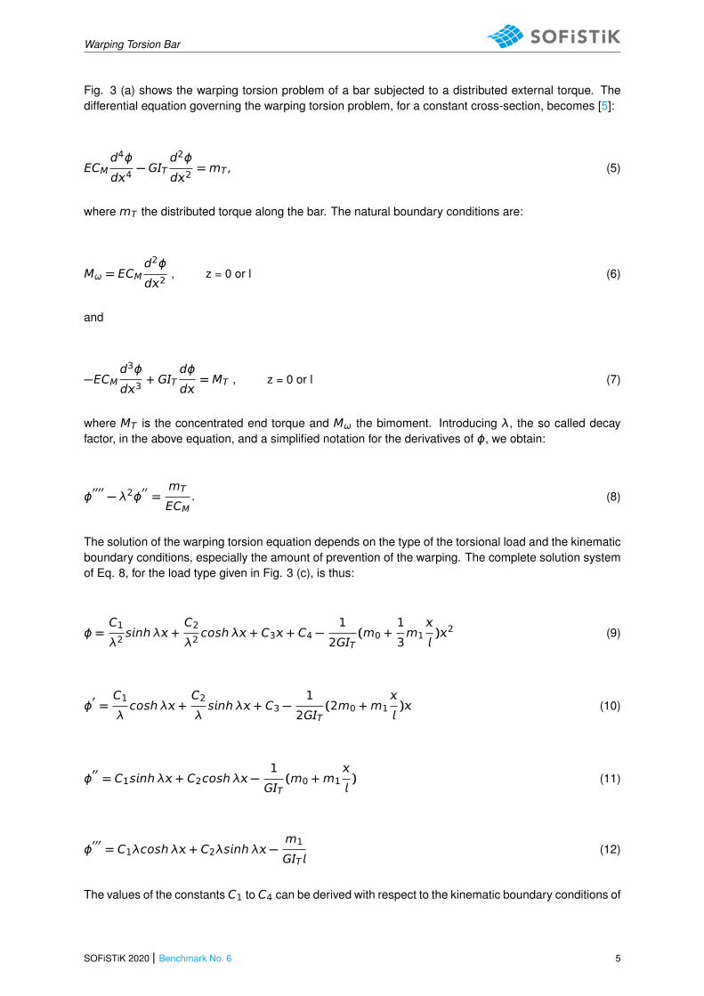
Figure 3: The Warping Torsion Problem
4 Benchmark No. 6 | SOFiSTiK 2020
Warping Torsion Bar
Fig. 3 (a) shows the warping torsion problem of a bar subjected to a distributed external torque. Thedifferential equation governing the warping torsion problem, for a constant cross-section, becomes [5]:
ECMd4ϕ
d4− GT
d2ϕ
d2=mT , (5)
where mT the distributed torque along the bar. The natural boundary conditions are:
Mω = ECMd2ϕ
d2, z = 0 or l (6)
and
−ECMd3ϕ
d3+ GT
dϕ
d= MT , z = 0 or l (7)
where MT is the concentrated end torque and Mω the bimoment. Introducing λ, the so called decayfactor, in the above equation, and a simplified notation for the derivatives of ϕ, we obtain:
ϕ′′′′− λ2ϕ
′′=
mT
ECM. (8)
The solution of the warping torsion equation depends on the type of the torsional load and the kinematicboundary conditions, especially the amount of prevention of the warping. The complete solution systemof Eq. 8, for the load type given in Fig. 3 (c), is thus:
ϕ =C1
λ2snh λ +
C2
λ2cosh λ + C3 + C4 −
1
2GT(m0 +
1
3m1
)2 (9)
ϕ′=C1
λcosh λ +
C2
λsnh λ + C3 −
1
2GT(2m0 +m1
) (10)
ϕ′′= C1snh λ + C2cosh λ −
1
GT(m0 +m1
) (11)
ϕ′′′= C1λcosh λ + C2λsnh λ −
m1
GT (12)
The values of the constants C1 to C4 can be derived with respect to the kinematic boundary conditions of
SOFiSTiK 2020 | Benchmark No. 6 5
Warping Torsion Bar
the problem. For the case of warping-free sections, where CM = 0, the differential equation is shortened,leading to the St. Venant torsion problem.
3 Model and Results
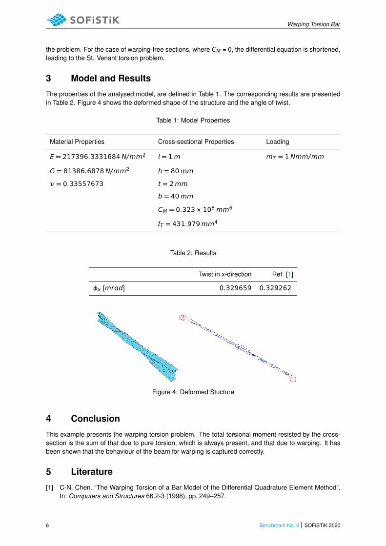
The properties of the analysed model, are defined in Table 1. The corresponding results are presentedin Table 2. Figure 4 shows the deformed shape of the structure and the angle of twist.
Table 1: Model Properties
Material Properties Cross-sectional Properties Loading
E = 217396.3331684N/mm2 = 1m mT = 1Nmm/mm
G = 81386.6878N/mm2 h = 80mm
ν = 0.33557673 t = 2mm
b = 40mm
CM = 0.323 × 108mm6
T = 431.979mm4
Table 2: Results
Twist in x-direction Ref. [1]
ϕ [mrd] 0.329659 0.329262
Figure 4: Deformed Stucture
4 Conclusion
This example presents the warping torsion problem. The total torsional moment resisted by the cross-section is the sum of that due to pure torsion, which is always present, and that due to warping. It hasbeen shown that the behaviour of the beam for warping is captured correctly.
5 Literature
[1] C-N. Chen. “The Warping Torsion of a Bar Model of the Differential Quadrature Element Method”.In: Computers and Structures 66.2-3 (1998), pp. 249–257.
6 Benchmark No. 6 | SOFiSTiK 2020
Warping Torsion Bar
[2] S. Timoshenko. Strength of Materials, Part II, Advanced Theory and Problems. 2nd. D. Van Nos-trand Co., Inc., 1940.
[3] F.P. Beer, E.R. Johnston, and J.T. DeWolf. Mechanics of Materials. 4th. McGraw-Hill, 2006.[4] P. Seaburg and C.J. Carter. Steel Design Guide Series 9: Torsional Analysis of Structural Steel
Members. AISC. 2003.[5] C. Petersen. Stahlbau. 2nd. Vieweg, 1990.
SOFiSTiK 2020 | Benchmark No. 6 7