Embed Size (px)
Citation preview
Water Source Heat Pump
Axiom™ High Efficiency Console — GEC
.5 to 1.5Tons — 50/60 Hz
May 2016 WSHP-PRC019D-EN
Product Catalog
© 2016 Ingersoll Rand All rights reserved WSHP-PRC019D-EN
Introduction
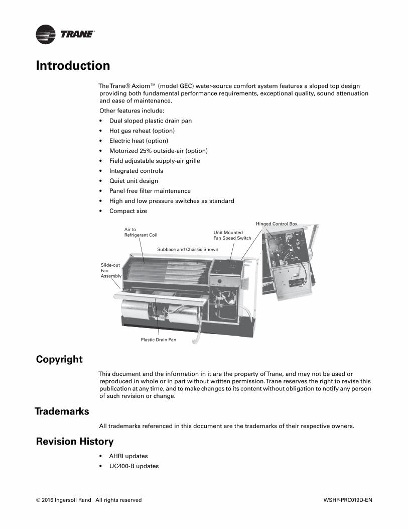
TheTrane® Axiom™ (model GEC) water-source comfort system features a sloped top designproviding both fundamental performance requirements, exceptional quality, sound attenuationand ease of maintenance.
Other features include:
• Dual sloped plastic drain pan
• Hot gas reheat (option)
• Electric heat (option)
• Motorized 25% outside-air (option)
• Field adjustable supply-air grille
• Integrated controls
• Quiet unit design
• Panel free filter maintenance
• High and low pressure switches as standard
• Compact size
Copyright
This document and the information in it are the property ofTrane, and may not be used orreproduced in whole or in part without written permission.Trane reserves the right to revise thispublication at any time, and to make changes to its content without obligation to notify any personof such revision or change.
Trademarks
All trademarks referenced in this document are the trademarks of their respective owners.
Revision History
• AHRI updates
• UC400-B updates
Unit Mounted Fan Speed Switch
Subbase and Chassis Shown
Air toRefrigerant Coil
Slide-outFan Assembly
Plastic Drain Pan
Hinged Control Box
WSHP-PRC019D-EN 3
Table of Contents
Introduction . . . . . . . . . . . . . . . . . . . . . . . . . . . . . . . . . . . . . . . . . . . . . . . . . . . . . . 2
Features and Benefits . . . . . . . . . . . . . . . . . . . . . . . . . . . . . . . . . . . . . . . . . . . . . . 4
Design . . . . . . . . . . . . . . . . . . . . . . . . . . . . . . . . . . . . . . . . . . . . . . . . . . . . . . . . 4Cabinet . . . . . . . . . . . . . . . . . . . . . . . . . . . . . . . . . . . . . . . . . . . . . . . . . . . . . . 4Field Flexibility . . . . . . . . . . . . . . . . . . . . . . . . . . . . . . . . . . . . . . . . . . . . . . . . 5Right Hand Piping . . . . . . . . . . . . . . . . . . . . . . . . . . . . . . . . . . . . . . . . . . . . . 5Left Hand Piping . . . . . . . . . . . . . . . . . . . . . . . . . . . . . . . . . . . . . . . . . . . . . . 5Sound Data . . . . . . . . . . . . . . . . . . . . . . . . . . . . . . . . . . . . . . . . . . . . . . . . . 11
Application Considerations . . . . . . . . . . . . . . . . . . . . . . . . . . . . . . . . . . . . . . . . . 14
Geothermal System . . . . . . . . . . . . . . . . . . . . . . . . . . . . . . . . . . . . . . . . . . . . 14Central Pumping for the GEC Product . . . . . . . . . . . . . . . . . . . . . . . . . . . . 15Installation Considerations . . . . . . . . . . . . . . . . . . . . . . . . . . . . . . . . . . . . . 16
Selection Procedure . . . . . . . . . . . . . . . . . . . . . . . . . . . . . . . . . . . . . . . . . . . . . . . 18Cooling Dominated Applications . . . . . . . . . . . . . . . . . . . . . . . . . . . . . . . . 18Heating Dominated Applications . . . . . . . . . . . . . . . . . . . . . . . . . . . . . . . . 18
Model Number Description . . . . . . . . . . . . . . . . . . . . . . . . . . . . . . . . . . . . . . . . . 20
General Data . . . . . . . . . . . . . . . . . . . . . . . . . . . . . . . . . . . . . . . . . . . . . . . . . . . . . 21
Performance Data . . . . . . . . . . . . . . . . . . . . . . . . . . . . . . . . . . . . . . . . . . . . . . . . 22Examples . . . . . . . . . . . . . . . . . . . . . . . . . . . . . . . . . . . . . . . . . . . . . . . . . . . 39
Electrical Data . . . . . . . . . . . . . . . . . . . . . . . . . . . . . . . . . . . . . . . . . . . . . . . . . . . . 40
Wiring Diagrams . . . . . . . . . . . . . . . . . . . . . . . . . . . . . . . . . . . . . . . . . . . . . . . . . 42
Unit Dimensions . . . . . . . . . . . . . . . . . . . . . . . . . . . . . . . . . . . . . . . . . . . . . . . . . 47
Service Clearances . . . . . . . . . . . . . . . . . . . . . . . . . . . . . . . . . . . . . . . . . . . . . 47
Weights . . . . . . . . . . . . . . . . . . . . . . . . . . . . . . . . . . . . . . . . . . . . . . . . . . . . . . . . . 59
Controls . . . . . . . . . . . . . . . . . . . . . . . . . . . . . . . . . . . . . . . . . . . . . . . . . . . . . . . . 60
Basic 24V Controls . . . . . . . . . . . . . . . . . . . . . . . . . . . . . . . . . . . . . . . . . . . . . 60Anti-short Cycle Timer . . . . . . . . . . . . . . . . . . . . . . . . . . . . . . . . . . . . . . . . 60Stand-alone System . . . . . . . . . . . . . . . . . . . . . . . . . . . . . . . . . . . . . . . . . . 60
Deluxe 24V electronic controls include: . . . . . . . . . . . . . . . . . . . . . . . . . . . . 61Deluxe 24V features . . . . . . . . . . . . . . . . . . . . . . . . . . . . . . . . . . . . . . . . . . 62Tracer® UC400-B . . . . . . . . . . . . . . . . . . . . . . . . . . . . . . . . . . . . . . . . . . . . . 63Tracer® ZN524 . . . . . . . . . . . . . . . . . . . . . . . . . . . . . . . . . . . . . . . . . . . . . . . 63Tracer® UC400-B/ZN524 functions include: . . . . . . . . . . . . . . . . . . . . . . . 63Trane® Air-Fi™ Wireless Systems . . . . . . . . . . . . . . . . . . . . . . . . . . . . . . . 66
Thermostats and Zone Sensors . . . . . . . . . . . . . . . . . . . . . . . . . . . . . . . . . . . . . 68
Mechanical Specifications . . . . . . . . . . . . . . . . . . . . . . . . . . . . . . . . . . . . . . . . . . 71Electrical . . . . . . . . . . . . . . . . . . . . . . . . . . . . . . . . . . . . . . . . . . . . . . . . . . . . 71
Features and Benefits
Design
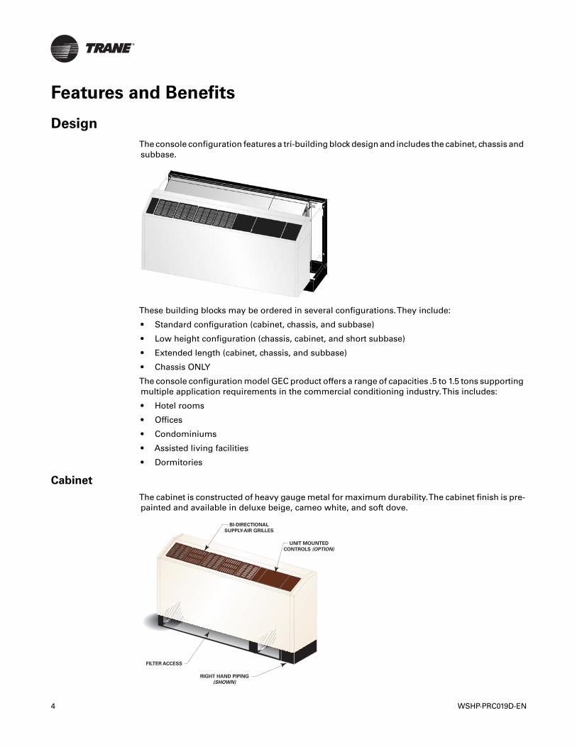
The console configuration features a tri-building block design and includes the cabinet, chassis andsubbase.
These building blocks may be ordered in several configurations.They include:
• Standard configuration (cabinet, chassis, and subbase)
• Low height configuration (chassis, cabinet, and short subbase)
• Extended length (cabinet, chassis, and subbase)
• Chassis ONLY
The console configuration model GEC product offers a range of capacities .5 to 1.5 tons supportingmultiple application requirements in the commercial conditioning industry.This includes:
• Hotel rooms
• Offices
• Condominiums
• Assisted living facilities
• Dormitories
Cabinet
The cabinet is constructed of heavy gauge metal for maximum durability.The cabinet finish is pre-painted and available in deluxe beige, cameo white, and soft dove.
BI-DIRECTIONAL
SUPPLY-AIR GRILLES
UNIT MOUNTED
CONTROLS (OPTION)
FILTER ACCESS
RIGHT HAND PIPING
(SHOWN)
4 WSHP-PRC019D-EN
Features and Benefits
The cabinet design includes a hook-secure fit that allows complete access to piping and electricalhook-up for ease of maintenance and serviceability.The single cabinet assembly is securelyfastened into the wall sleeve with four 5/16” bolts.
Field Flexibility
Piping and electrical connections to the console are made in either the left or right hand end pocket.The unit refrigeration platform and the unit control box is maintained in the same location whetherleft or right hand piping, standard unit cabinet, extended unit cabinet, or low height unit cabinethas been specified.This cloned platform poses a common look and feel to the installer, as well asaids in troubleshooting during service or maintenance check-ups.
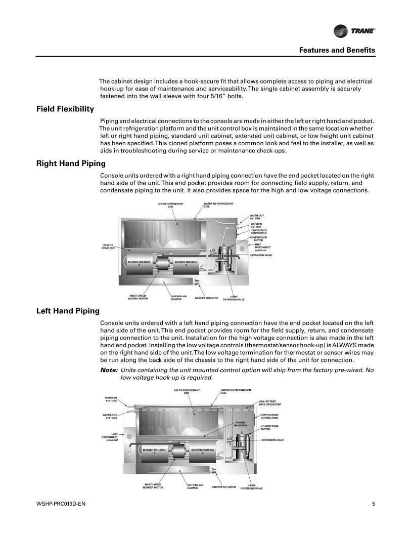
Right Hand Piping
Console units ordered with a right hand piping connection have the end pocket located on the righthand side of the unit.This end pocket provides room for connecting field supply, return, andcondensate piping to the unit. It also provides space for the high and low voltage connections.
Left Hand Piping
Console units ordered with a left hand piping connection have the end pocket located on the lefthand side of the unit.This end pocket provides room for the field supply, return, and condensatepiping connection to the unit. Installation for the high voltage connection is also made in the lefthand end pocket. Installing the low voltage controls (thermostat/sensor hook-up) isALWAYS madeon the right hand side of the unit.The low voltage termination for thermostat or sensor wires maybe run along the back side of the chassis to the right hand side of the unit for connection.
Note: Units containing the unit mounted control option will ship from the factory pre-wired. Nolow voltage hook-up is required.
WSHP-PRC019D-EN 5
Features and Benefits
Air-to-Refrigerant Coil
The air-to-refrigerant heat exchanger is constructed of staggered copper tubes with die-formedcorrugated lanced aluminum fins.The fins are then mechanically bonded to the tubes throughexpansion.
The maximum working pressure of the coil is 650 psig. It is designed for maximum capacity withan additional benefit of physical unit size reduction.
Coil specifications for the GEC unit are in the following table.
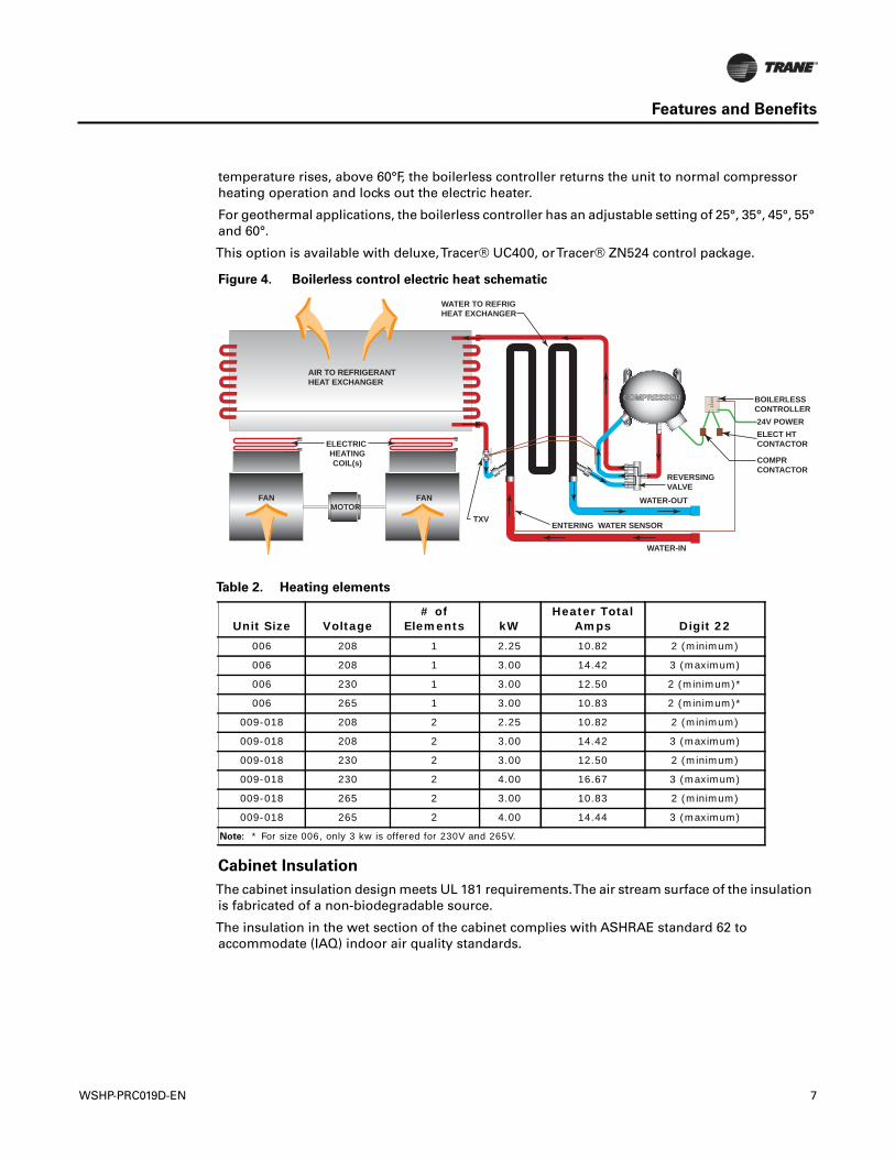
Boilerless Control, Electric Heat System (option)
The boilerless electric heat option is composed of a nichrome open wire heating element with aninternal temperature limit placed above the fan housing and an electronic (boilerless) controllerlocated in the main control box.
The boilerless control option is comprised of a single stage of electric heat and is designed toinvoice electric heat in the event that entering-water temperatures falls below 55°F. On a call forheating, the electric heater is energized, locking out the compressor. Once the entering water
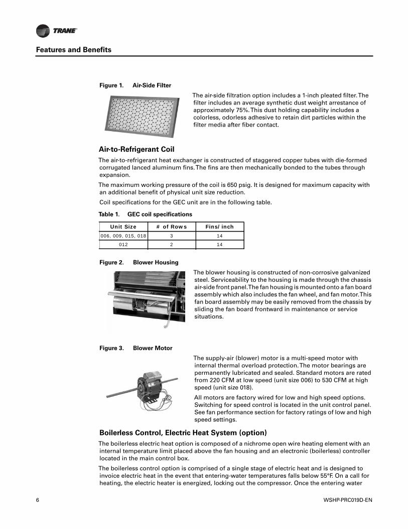
Figure 1. Air-Side Filter
The air-side filtration option includes a 1-inch pleated filter.Thefilter includes an average synthetic dust weight arrestance ofapproximately 75%.This dust holding capability includes acolorless, odorless adhesive to retain dirt particles within thefilter media after fiber contact.
Table 1. GEC coil specifications
Unit Size # of Rows Fins/inch006, 009, 015, 018 3 14
012 2 14
Figure 2. Blower Housing
The blower housing is constructed of non-corrosive galvanizedsteel. Serviceability to the housing is made through the chassisair-side front panel.The fan housing is mounted onto a fan boardassembly which also includes the fan wheel, and fan motor.Thisfan board assembly may be easily removed from the chassis bysliding the fan board frontward in maintenance or servicesituations.
Figure 3. Blower Motor
The supply-air (blower) motor is a multi-speed motor withinternal thermal overload protection.The motor bearings arepermanently lubricated and sealed. Standard motors are ratedfrom 220 CFM at low speed (unit size 006) to 530 CFM at highspeed (unit size 018).
All motors are factory wired for low and high speed options.Switching for speed control is located in the unit control panel.See fan performance section for factory ratings of low and highspeed settings.
6 WSHP-PRC019D-EN
Features and Benefits
temperature rises, above 60°F, the boilerless controller returns the unit to normal compressorheating operation and locks out the electric heater.
For geothermal applications, the boilerless controller has an adjustable setting of 25°, 35°, 45°, 55°and 60°.
This option is available with deluxe,Tracer® UC400, orTracer® ZN524 control package.
Cabinet Insulation
The cabinet insulation design meets UL 181 requirements.The air stream surface of the insulationis fabricated of a non-biodegradable source.
The insulation in the wet section of the cabinet complies with ASHRAE standard 62 toaccommodate (IAQ) indoor air quality standards.
Figure 4. Boilerless control electric heat schematic
Table 2. Heating elements
Unit Size Voltage# of
Elements kWHeater Total
Amps Digit 22006 208 1 2.25 10.82 2 (minimum)
006 208 1 3.00 14.42 3 (maximum)
006 230 1 3.00 12.50 2 (minimum)*
006 265 1 3.00 10.83 2 (minimum)*
009-018 208 2 2.25 10.82 2 (minimum)
009-018 208 2 3.00 14.42 3 (maximum)
009-018 230 2 3.00 12.50 2 (minimum)
009-018 230 2 4.00 16.67 3 (maximum)
009-018 265 2 3.00 10.83 2 (minimum)
009-018 265 2 4.00 14.44 3 (maximum)
Note: * For size 006, only 3 kw is offered for 230V and 265V.
COMPRESSORCOMPRESSOR
AIR TO REFRIGERANTHEAT EXCHANGER
ELECTRIC HEATINGCOIL(s)
WATER-OUT
ENTERING WATER SENSOR
REVERSINGVALVE
24V POWERELECT HTCONTACTOR
COMPRCONTACTOR
BOILERLESSCONTROLLER
WATER TO REFRIGHEAT EXCHANGER
FANFANMOTOR
WATER-IN
TXV
2535455560
WSHP-PRC019D-EN 7
Features and Benefits
Compressor and Co-axial Coil Isolation
Vibration isolation for the compressor and co-axial water coil is accomplished by increasing therigidity and stiffness at the base for the compressor, and at the back of the chassis for the co-axialwater coil.This platform includes double isolation to the compressor and single isolation to the co-axial water coil.
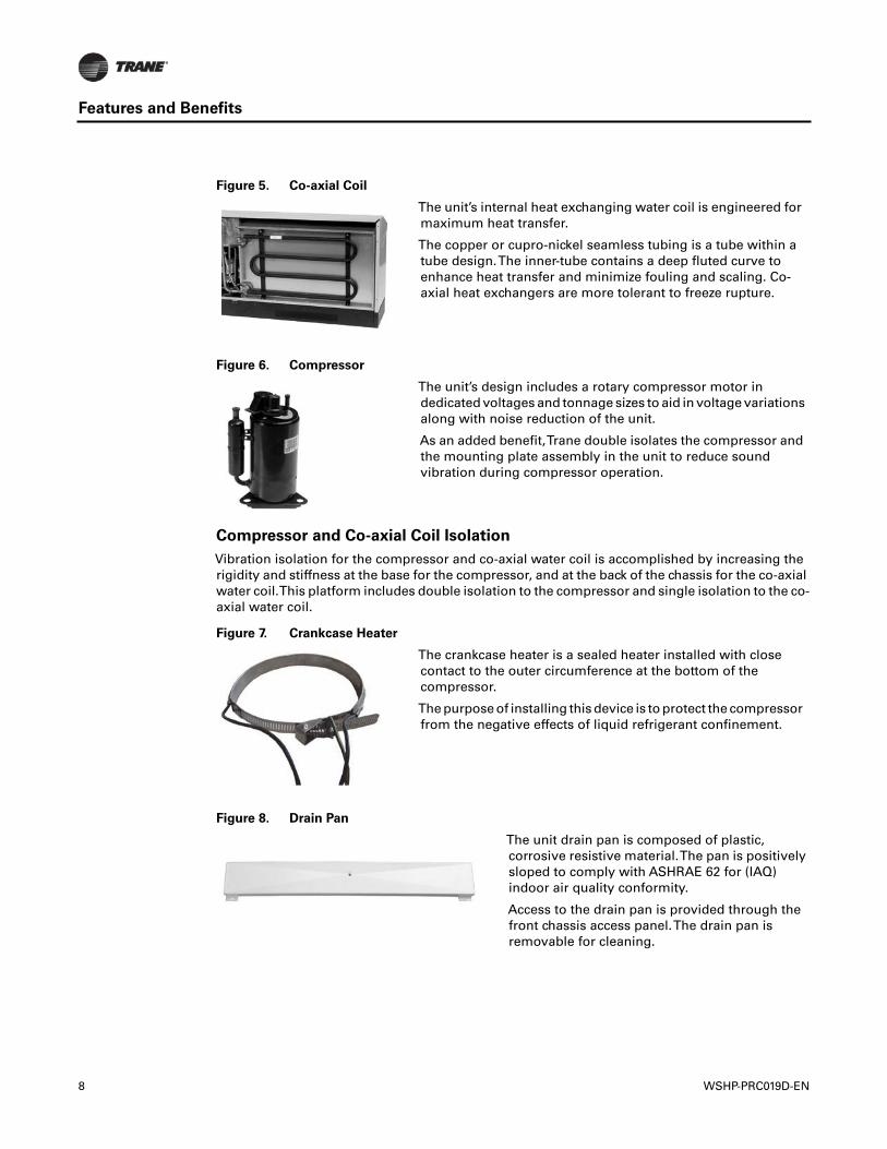
Figure 5. Co-axial Coil
The unit’s internal heat exchanging water coil is engineered formaximum heat transfer.
The copper or cupro-nickel seamless tubing is a tube within atube design.The inner-tube contains a deep fluted curve toenhance heat transfer and minimize fouling and scaling. Co-axial heat exchangers are more tolerant to freeze rupture.
Figure 6. Compressor
The unit’s design includes a rotary compressor motor indedicated voltages and tonnage sizes to aid in voltage variationsalong with noise reduction of the unit.
As an added benefit,Trane double isolates the compressor andthe mounting plate assembly in the unit to reduce soundvibration during compressor operation.
Figure 7. Crankcase Heater
The crankcase heater is a sealed heater installed with closecontact to the outer circumference at the bottom of thecompressor.
The purpose of installing this device is to protect the compressorfrom the negative effects of liquid refrigerant confinement.
Figure 8. Drain Pan
The unit drain pan is composed of plastic,corrosive resistive material.The pan is positivelysloped to comply with ASHRAE 62 for (IAQ)indoor air quality conformity.
Access to the drain pan is provided through thefront chassis access panel.The drain pan isremovable for cleaning.
8 WSHP-PRC019D-EN
Features and Benefits
Hot Gas Reheat (option)
For true atmospheric conditioning and climate control,Trane provides accurate, cost effectivedehumidification control through a hot gas reheat option.
With this reheat option, the return air from the space is cooled by the air-to-refrigerant coil, thenreheated by the reheat coil to control not only space temperature, but to also reduce the relativehumidity of the space.The amount of moisture removal of a specific heat pump is determined bythe unit’s latent capacity rating.
When operating in the reheat mode, the humidistat signals the reheat relay coil to energize,allowing the high pressure refrigerant gas to flow from the compressor, through the reversingvalve, into the reheat valve, for passage through the reheat coil.
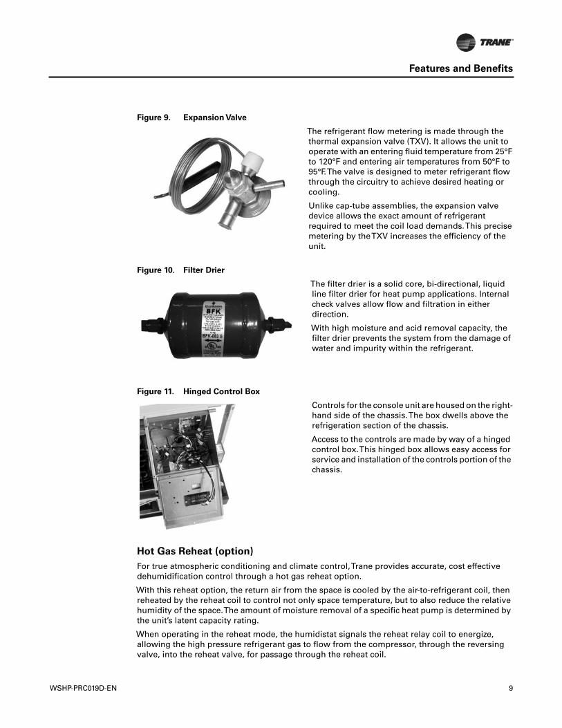
Figure 9. Expansion Valve
The refrigerant flow metering is made through thethermal expansion valve (TXV). It allows the unit tooperate with an entering fluid temperature from 25°Fto 120°F and entering air temperatures from 50°F to95°F.The valve is designed to meter refrigerant flowthrough the circuitry to achieve desired heating orcooling.
Unlike cap-tube assemblies, the expansion valvedevice allows the exact amount of refrigerantrequired to meet the coil load demands.This precisemetering by theTXV increases the efficiency of theunit.
Figure 10. Filter Drier
The filter drier is a solid core, bi-directional, liquidline filter drier for heat pump applications. Internalcheck valves allow flow and filtration in eitherdirection.
With high moisture and acid removal capacity, thefilter drier prevents the system from the damage ofwater and impurity within the refrigerant.
Figure 11. Hinged Control Box
Controls for the console unit are housed on the right-hand side of the chassis.The box dwells above therefrigeration section of the chassis.
Access to the controls are made by way of a hingedcontrol box.This hinged box allows easy access forservice and installation of the controls portion of thechassis.
WSHP-PRC019D-EN 9
Features and Benefits
Note: The hot gas reheat option is available with Deluxe,Tracer® UC400 orTracer® ZN524 controlpackage.
Common Reheat Applications
• Conditioned-air delivered directly to the space.
• Auditoriums, theaters, classrooms or where a large latent load exists.
• Computer room space conditioning.
• Anywhere humidity control is a problem.
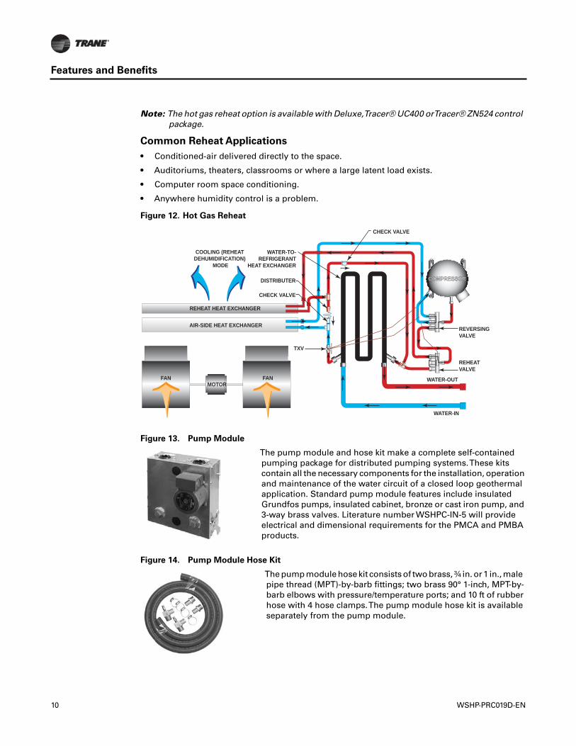
Figure 12. Hot Gas Reheat
Figure 13. Pump Module
The pump module and hose kit make a complete self-containedpumping package for distributed pumping systems.These kitscontain all the necessary components for the installation, operationand maintenance of the water circuit of a closed loop geothermalapplication. Standard pump module features include insulatedGrundfos pumps, insulated cabinet, bronze or cast iron pump, and3-way brass valves. Literature number WSHPC-IN-5 will provideelectrical and dimensional requirements for the PMCA and PMBAproducts.
Figure 14. Pump Module Hose Kit
The pump module hose kit consists of two brass, ¾ in. or 1 in., malepipe thread (MPT)-by-barb fittings; two brass 90° 1-inch, MPT-by-barb elbows with pressure/temperature ports; and 10 ft of rubberhose with 4 hose clamps.The pump module hose kit is availableseparately from the pump module.
REHEAT HEAT EXCHANGER
AIR-SIDE HEAT EXCHANGER
COOLING (REHEATDEHUMIDIFICATION)
MODE
FANFANMOTOR
TXV
COMPRESSORCOMPRESSOR
WATER-OUT
REVERSINGVALVE
REHEATVALVE
CHECK VALVE
WATER-TO-REFRIGERANT
HEAT EXCHANGER
CHECK VALVE
DISTRIBUTER
WATER-IN
10 WSHP-PRC019D-EN
Features and Benefits
Refrigerant Piping
The unit's copper tubing is created from a 99% pure copper formation that conforms to theAmerican Society ofTesting (ASTM) B743 for seamless, light-annealed processing.
The unit's copper refrigeration system is designed to be free from contaminants and conditionssuch as drilling fragments, dirt, or oil.This excludes the possibility of these contaminants fromdamaging the compressor motor.
Schrader Connections
The refrigerant access ports shall be factory supplied on the high and low pressure sides for easyrefrigerant pressure or temperature testing.
Supply-Air Registers
Supply-air registers for the GEC product are constructed of a plastic, corrosive resistive material.The registers include a snap-in deflection design to simplify installation, as well as facilitate theability to apply a bi-directional arrangement across the register
Sound Data
Sound Attenuation Package
The console equipment is designed to achieve the lowest noise levels possible. Extensive testinghas identified the major sound generating sources within the console unit package. Every effort hasbeen made to minimize the sound generation and transmission from the compressor, heatexchangers, and fan sources. Vibration transmission from the compressor and heat exchangershave been minimized by the use of isolation.The use of heavy metal gauges in critical areasenhance the unit acoustic performance. A patented two-stage compressor isolation system hasbeen specifically designed for the console unit. Acoustic lining has been used to quiet compressornoise.
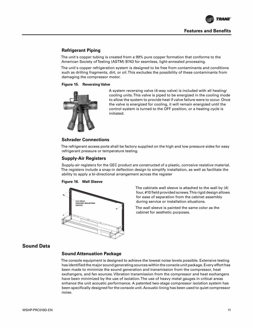
Figure 15. Reversing Valve
A system reversing valve (4-way valve) is included with all heating/cooling units.This valve is piped to be energized in the cooling modeto allow the system to provide heat if valve failure were to occur. Oncethe valve is energized for cooling, it will remain energized until thecontrol system is turned to the OFF position, or a heating cycle isinitiated.
Figure 16. Wall Sleeve
The cabinets wall sleeve is attached to the wall by (4)four, #10 field provided screws.This rigid design allowsfor ease of separation from the cabinet assemblyduring service or installation situations.
The wall sleeve is painted the same color as thecabinet for aesthetic purposes.
#10 FIELDPROVIDE MOUNTINGDEVICE
WSHP-PRC019D-EN 11
Features and Benefits
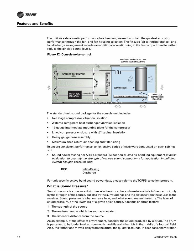
The unit air side acoustic performance has been engineered to obtain the quietest acousticperformance through the fan, and fan housing selection.The fin tube (air-to-refrigerant) coil andfan discharge arrangement includes an additional acoustic lining in the fan compartment to furtherreduce the air side sound levels.
The standard unit sound package for the console unit includes:
• Two stage compressor vibration isolation
• Water-to-refrigerant heat exchanger vibration isolation
• 12-gauge intermediate mounting plate for the compressor
• Lined compressor enclosure with ½” cabinet insulation
• Heavy gauge base assembly
• Maximum sized return-air opening and filter sizing
To ensure consistent performance, an extensive series of tests were conducted on each cabinetsize.
• Sound power testing per AHRI’s standard 350 for non-ducted air handling equipment (a noiseevaluation to quantify the strength of various sound components for application in buildingsystem design).These include:
For unit specific octave band sound power data, please refer to theTOPPS selection program.
What is Sound Pressure?
Sound pressure is a pressure disturbance in the atmosphere whose intensity is influenced not onlyby the strength of the source, but also by the surroundings and the distance from the source to thereceiver. Sound pressure is what our ears hear, and what sound meters measure.The level ofsound pressure, or the loudness of a given noise source, depends on three factors:
1. The strength of the source
2. The environment in which the source is located
3. The listener’s distance from the source
As an example, of the effect of environment, consider the sound produced by a drum.The drumis perceived to be louder in a bathroom with hard tile walls than it is in the middle of a football field.Also, the farther one moves away from the drum, the quieter it sounds. In each case, the vibration
Figure 17. Console noise control
GEC: Inlet+CasingDischarge
LINED AND SEALED
COMPRESSOR ENCLOSURE
HEAVY GAUGE BASE ASSEMBLY
12 GAUGE COMPRESSOR PLATETWO-STAGE
COMPRESSOR
ISOLATION
COMPRESSOR
AIR
-TO
-RE
FR
IGE
RA
NT
CO
IL
WATER-TO-REFRIGERANT
COIL
WATER COIL
ISOLATION
12 WSHP-PRC019D-EN
Features and Benefits
of the drum (the strength of the source) is the same; the perceived differences in noise level aredue to the environment.
Because of the extremely wide range of sound pressure perceivable by a person—typically five orsix order of magnitude-it is convenient to express sound pressure on a logarithmic scale. As aresult, adding two equal sound sources together will result in an overall increase of 3 dB. However,3 dB is barely a perceptible increase in sound. It takes an increase of 10 dB to be perceived as twiceas loud.
What is Sound Power?
Sound power is a measure of the acoustical energy emitted from a sound source, and is an absolutevalue. As discussed above, our hearing does not perceive sound power directly, as there is alwayssome environmental medium between the source and the listener. However, from the standpointof a building designer, sound power is often the preferred means of quantifying the noise of a givenunit because it is a certifiable quantity. Using predictions are used to tailor the design to the soundpressure level requirements of the building.The environmental effects that must be taken intoaccount when converting sound power to sound pressure for a specific location can be lumpedtogether and called the transfer function.
Sound power should always be used when making unit-to-unit sound comparisons because it isa certifiable absolute measure of the sound energy produced by the unit. In contrast, soundpressure is not certifiable because it is difficult to ensure that each manufacturer tests in preciselythe same environment. As in the case of sound pressure, it is useful to express sound power ona logarithmic scale.
What are NC and dBA?
Both NC and dBA are single number descriptors used to represent perceived loudness. Both scalestake into account the fact that people are more sensitive to high frequencies than they are to lowfrequencies.
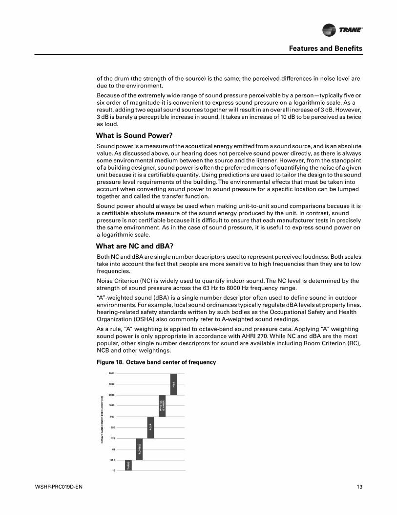
Noise Criterion (NC) is widely used to quantify indoor sound.The NC level is determined by thestrength of sound pressure across the 63 Hz to 8000 Hz frequency range.
“A”-weighted sound (dBA) is a single number descriptor often used to define sound in outdoorenvironments. For example, local sound ordinances typically regulate dBA levels at property lines.hearing-related safety standards written by such bodies as the Occupational Safety and HealthOrganization (OSHA) also commonly refer to A-weighted sound readings.
As a rule, “A” weighting is applied to octave-band sound pressure data. Applying “A” weightingsound power is only appropriate in accordance with AHRI 270. While NC and dBA are the mostpopular, other single number descriptors for sound are available including Room Criterion (RC),NCB and other weightings.
Figure 18. Octave band center of frequency
WSHP-PRC019D-EN 13
Application Considerations
Geothermal System
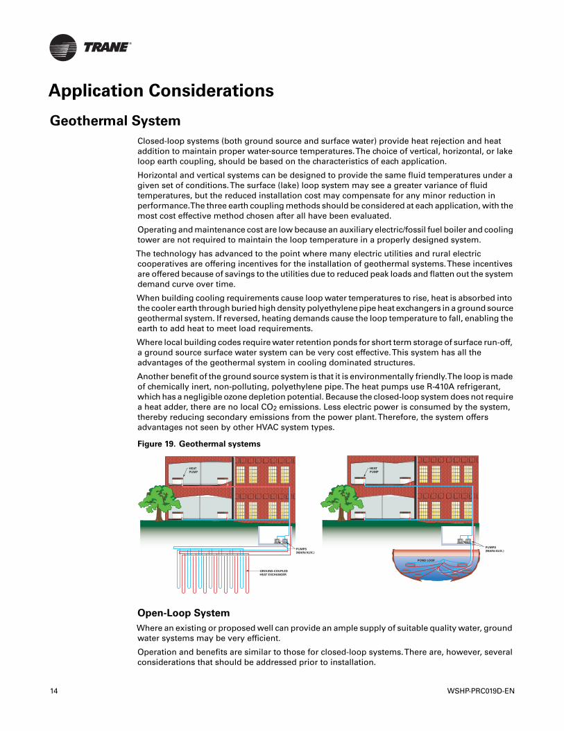
Closed-loop systems (both ground source and surface water) provide heat rejection and heataddition to maintain proper water-source temperatures.The choice of vertical, horizontal, or lakeloop earth coupling, should be based on the characteristics of each application.
Horizontal and vertical systems can be designed to provide the same fluid temperatures under agiven set of conditions.The surface (lake) loop system may see a greater variance of fluidtemperatures, but the reduced installation cost may compensate for any minor reduction inperformance.The three earth coupling methods should be considered at each application, with themost cost effective method chosen after all have been evaluated.
Operating and maintenance cost are low because an auxiliary electric/fossil fuel boiler and coolingtower are not required to maintain the loop temperature in a properly designed system.
The technology has advanced to the point where many electric utilities and rural electriccooperatives are offering incentives for the installation of geothermal systems.These incentivesare offered because of savings to the utilities due to reduced peak loads and flatten out the systemdemand curve over time.
When building cooling requirements cause loop water temperatures to rise, heat is absorbed intothe cooler earth through buried high density polyethylene pipe heat exchangers in a ground sourcegeothermal system. If reversed, heating demands cause the loop temperature to fall, enabling theearth to add heat to meet load requirements.
Where local building codes require water retention ponds for short term storage of surface run-off,a ground source surface water system can be very cost effective.This system has all theadvantages of the geothermal system in cooling dominated structures.
Another benefit of the ground source system is that it is environmentally friendly.The loop is madeof chemically inert, non-polluting, polyethylene pipe.The heat pumps use R-410A refrigerant,which has a negligible ozone depletion potential. Because the closed-loop system does not requirea heat adder, there are no local CO2 emissions. Less electric power is consumed by the system,thereby reducing secondary emissions from the power plant.Therefore, the system offersadvantages not seen by other HVAC system types.
Open-Loop System
Where an existing or proposed well can provide an ample supply of suitable quality water, groundwater systems may be very efficient.
Operation and benefits are similar to those for closed-loop systems.There are, however, severalconsiderations that should be addressed prior to installation.
Figure 19. Geothermal systems
HEAT
PUMP
PUMPS
(MAIN/AUX.)
GROUND-COUPLED
HEAT EXCHANGER
HEAT
PUMP
PUMPS
(MAIN/AUX.)
POND LOOP
14 WSHP-PRC019D-EN
Application Considerations
An acceptable way to discharge the significant volume of used water from the heat pump shouldbe defined. It may be necessary to install a recharge well to return the water to the aquifer.
Water quality must be acceptable, with minimal suspended solids and proper pH.To help ensureclean water, a straining device may be required.
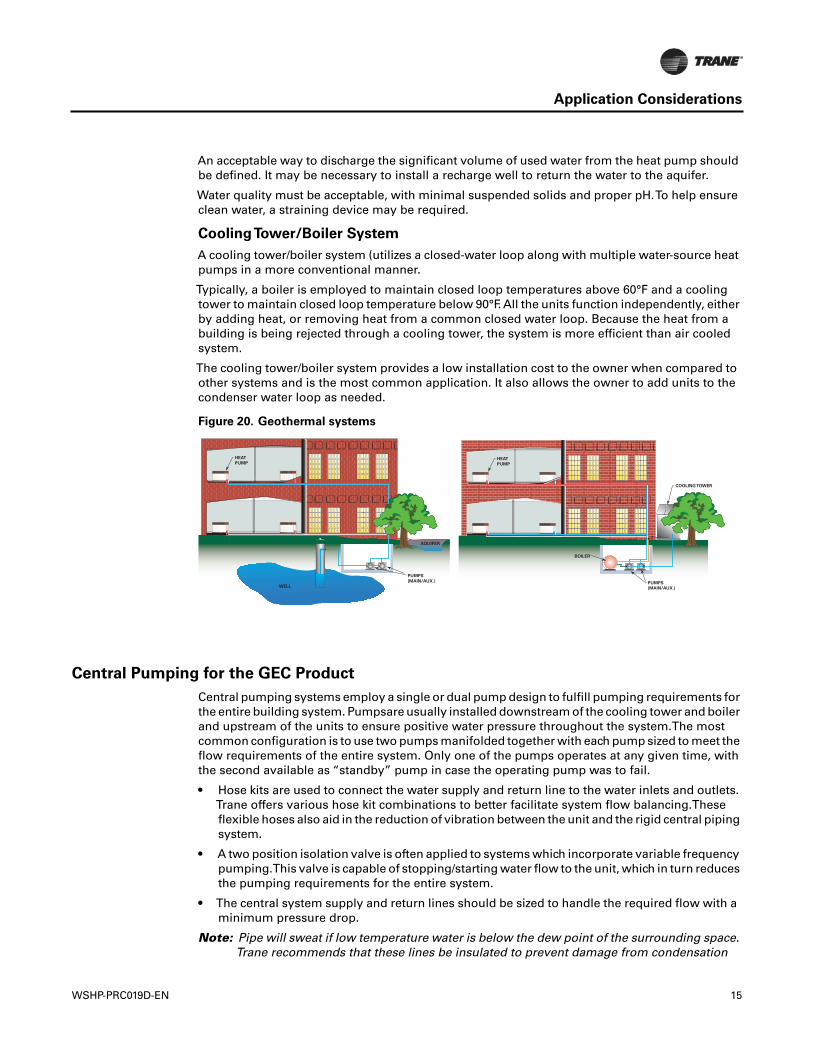
CoolingTower/Boiler System
A cooling tower/boiler system (utilizes a closed-water loop along with multiple water-source heatpumps in a more conventional manner.
Typically, a boiler is employed to maintain closed loop temperatures above 60°F and a coolingtower to maintain closed loop temperature below 90°F. All the units function independently, eitherby adding heat, or removing heat from a common closed water loop. Because the heat from abuilding is being rejected through a cooling tower, the system is more efficient than air cooledsystem.
The cooling tower/boiler system provides a low installation cost to the owner when compared toother systems and is the most common application. It also allows the owner to add units to thecondenser water loop as needed.
Central Pumping for the GEC Product
Central pumping systems employ a single or dual pump design to fulfill pumping requirements forthe entire building system. Pumpsare usually installed downstream of the cooling tower and boilerand upstream of the units to ensure positive water pressure throughout the system.The mostcommon configuration is to use two pumps manifolded together with each pump sized to meet theflow requirements of the entire system. Only one of the pumps operates at any given time, withthe second available as “standby” pump in case the operating pump was to fail.
• Hose kits are used to connect the water supply and return line to the water inlets and outlets.Trane offers various hose kit combinations to better facilitate system flow balancing.Theseflexible hoses also aid in the reduction of vibration between the unit and the rigid central pipingsystem.
• A two position isolation valve is often applied to systems which incorporate variable frequencypumping.This valve is capable of stopping/starting water flow to the unit, which in turn reducesthe pumping requirements for the entire system.
• The central system supply and return lines should be sized to handle the required flow with aminimum pressure drop.
Note: Pipe will sweat if low temperature water is below the dew point of the surrounding space.Trane recommends that these lines be insulated to prevent damage from condensation
Figure 20. Geothermal systems
HEAT
PUMP
PUMPS
(MAIN/AUX.)
AQUIFER
WELL
HEAT
PUMP
BOILER
COOLING TOWER
PUMPS
(MAIN/AUX.)
WSHP-PRC019D-EN 15
Application Considerations
when condenser loop is designed to be below 60°F. Equipment installed in attic/crawl spacetemperatures below 40°F may require antifreeze in the water loop.
Installation Considerations
1. The field supplied line voltage disconnect with circuit breaker should be installed for branchcircuit protection.
2. The units high voltage connection is located in the right or left hand end pocket.The fieldconnection may be made to the factory ordered disconnect, or hard wired via the factorymounted 2 x 4 handy box.
3. The low voltage connections are made on the right hand side of the unit for units ordered withthe wall mounted thermostat or sensor options.The low voltage connection is factory made ifunit mounted controls are specified.
4. Because of the units blow-through design, no condensate trapping is necessary. However, it isnecessary for the condensate to run in a downward motion to allow gravity to produce aconstant outflow.
5. Hose kits are used to connect the water supply and return lines to the water inlet and outlets.Trane can provide various hose kit combinations to better facilitate system flow balancing.These flexible hoses, reduce vibration between the unit and the rigid piping system. For moreinformation on the types of hose kitsTrane recommends, reference WSHP-PRC025*-ENmanual.
6. The console design includes a factory provided wall sleeve to facilitate installation of the unitin it’s establishment.
7. The grilles are made of a durable plastic symmetrical design. The design constitutes the abilityof a multi-directional supply-air from the units top.
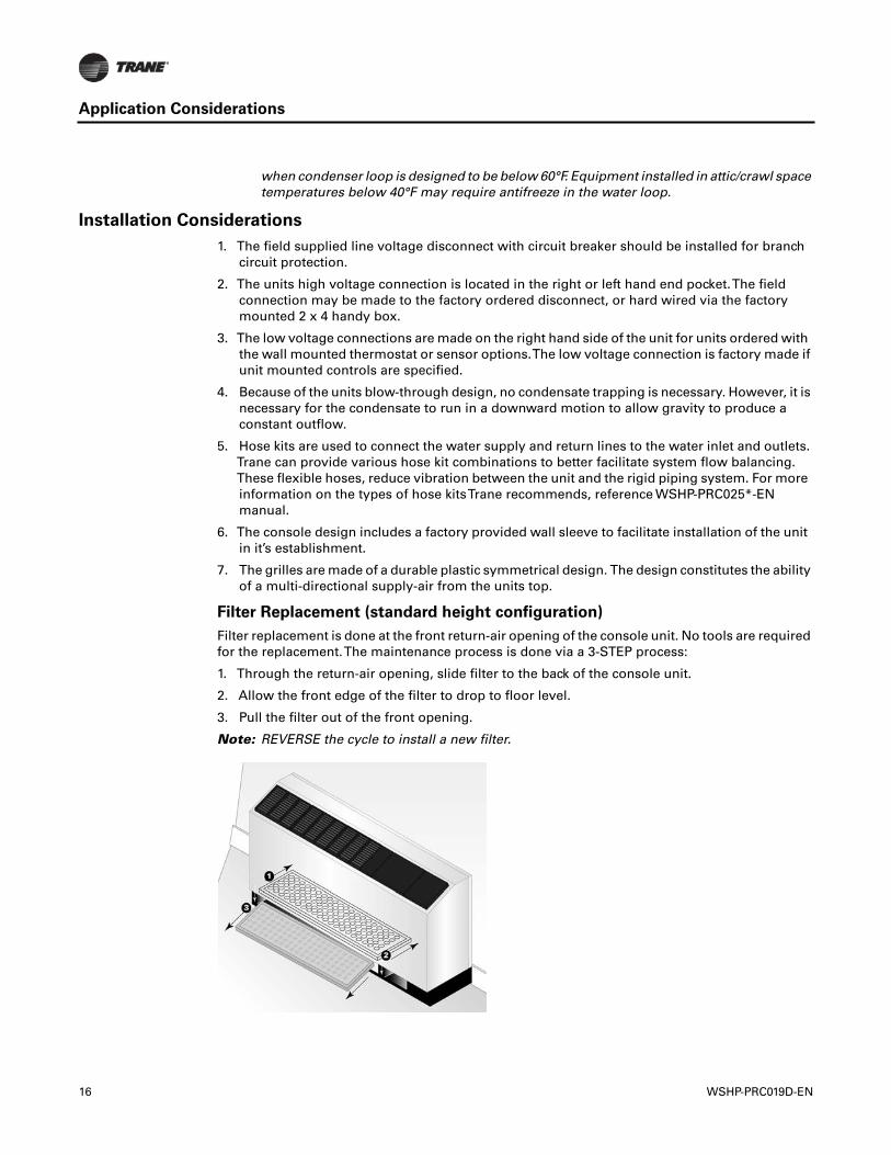
Filter Replacement (standard height configuration)
Filter replacement is done at the front return-air opening of the console unit. No tools are requiredfor the replacement.The maintenance process is done via a 3-STEP process:
1. Through the return-air opening, slide filter to the back of the console unit.
2. Allow the front edge of the filter to drop to floor level.
3. Pull the filter out of the front opening.
Note: REVERSE the cycle to install a new filter.
16 WSHP-PRC019D-EN
Application Considerations
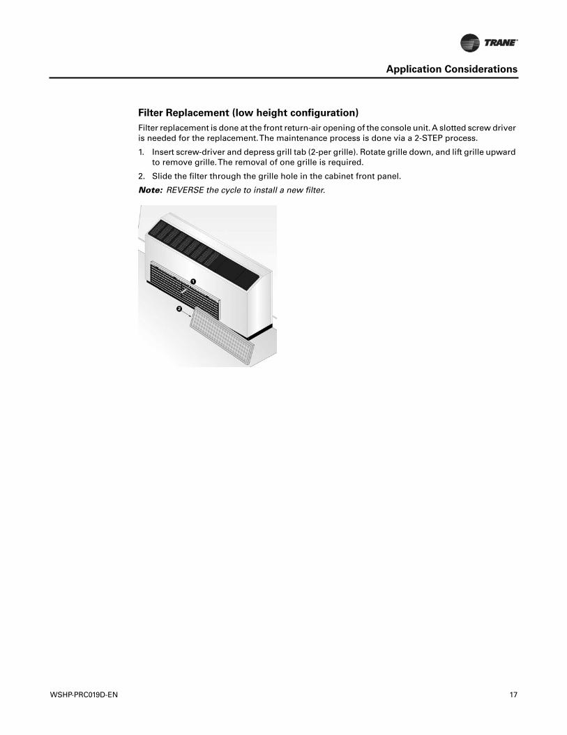
Filter Replacement (low height configuration)
Filter replacement is done at the front return-air opening of the console unit. A slotted screw driveris needed for the replacement.The maintenance process is done via a 2-STEP process.
1. Insert screw-driver and depress grill tab (2-per grille). Rotate grille down, and lift grille upwardto remove grille.The removal of one grille is required.
2. Slide the filter through the grille hole in the cabinet front panel.
Note: REVERSE the cycle to install a new filter.
WSHP-PRC019D-EN 17
Selection Procedure
The performance standard AHRI/ISO 13256-1 became effective Jan. 1, 2000. It replaces AHRIstandards 320, 325 and 330.This new standard has three major categories:Water Loop (AHRI 320),GroundWater (AHRI 325), Ground Loop (AHRI 330). Although these standards are similar there aresome differences.
The cooling efficiency is measured in EER but includes a Watt-per-Watt unit of measure similar tothe traditional COP measurement.
The entering water temperature has changed to reflect the centigrade temperature scale. Forinstance the water loop heating test is performed with 68°F water instead of 70°F.The cooling testsare performed with 80.6°F dry bulb and 66.2°F wet bulb entering air instead of the traditional 80°Fdry bulb, and 67°F wet bulb entering air temperatures.This data (80.6/66.2) may be converted to80/67 by using the entering air correction table.
A pump power correction has been added onto the existing power consumption. Within eachmodel, only one water flow rate is specified for each performance category, and pumping watts arecalculated utilizing the pump power correction formula: (gpm x 0.0631) x press drop x 2990) / 300.
Note: gpm relates to water flow, and press drop relates to the drop through the unit heatexchanger at rated water flow in feet of head.
The fan power is corrected to zero external static pressure.The nominal airflow is rated at a specificexternal static pressure.This effectively reduces the power consumption of the unit, and increasescooling capacity but decreases heating capacity.These watts are significant enough in most casesto increase EER and COP over AHRI 320, 325, and 330 ratings.
Cooling Dominated Applications
If humidity levels are moderate to high in a cooling dominated application, the heat pump shouldbe selected to meet or exceed the calculated sensible load.Also, the unit’s sensible capacity shouldbe no more than 115% of the total cooling load (sensible + latent), unless the calculated latent loadis less than the latent capacity of the unit.
The sensible-to-total cooling ratio can be adjusted with airflow. If the airflow is lowered, the unitlatent capacity will increase. When less air is pulled across the DX coil, more moisture willcondense from the air.
Heating Dominated Applications
Unit sizing in heating dominated applications is based upon humidity levels for the climate, andgoals for operating cost and installation costs.
If humidity levels are moderate, the heat pump should be selected with the heating capacity equalto 125% of the cooling load.
If humidity levels are low in the application and low operating cost is important, the heat pump andground loop should be sized for 90% to 100% of the heating load.
If humidity levels are low and lower initial cost is important, then the heat pump and ground loopshould be sized for 70% to 85% of the heating load, with the remaining load to be treated withelectric resistance heat.
Installation cost will be reduced in this approach because of the smaller heat pump selection andless loop materials.
In general, the system will not use enough electric heat to offset the higher installation costsassociated with a fully sized or oversized system.
Finally, a unit sized for the entire heating load in a heating dominated application will be oversizedin cooling. Comfort is reduced from increased room humidity caused by short-run times. Shortcycling will also shorten the life expectancy of the equipment and increase power consumption andoperating cost.
18 WSHP-PRC019D-EN

Selection Procedure
Many rebate incentives require the heat pump and ground loop to be sized for the entire heatingload. Check with your local utility for their requirements.
WSHP-PRC019D-EN 19

Model Number Description
Digits 1-3 — Unit ConfigurationGEC = High Efficiency Console
Digit 4 — Unit ConfigurationE
Digits 5-7 — Nominal Capacity006 =.5Tons009 =.75Tons012 = 1Tons015 =1.25Tons018 = 1.5Tons
Digit 8 — Voltage Volts/Hz/Phase)0 = 115/60/11 = 208/60/12 = 230/60/16 = 220-240/50/17 = 265/60/1
Digit 9 — Heat Exchanger1 = Copper-Water Coil2 = Cupro-Nickel Water Coil
Digit 10 — Design SequenceB
Digit 11 — Refrigeration Circuit0 = Heating and Cooling Circuit2 = Heating and Cooling Circuit with Hot
Gas Reheat
Digit 12 — Blower Configuration1= Standard Blower Motor
Digit 13 — Freeze Protection0 = None or StandardA = 20° FreezestatB = 35° Freezestat
Digit 14 — Open Digit0 = Open DigitS = Design Special
Digit 15 — Supply-AirArrangement0 = Standard Supply-Air Arrangement
Digit 16 — Return-AirArrangement0 = Standard Return-Air Arrangement
Digit 17 — ControlTypes0 = Basic 24V ControlsD = Deluxe 24V ControlsB = Tracer® ZN524 ControlsE = Deluxe 24V Control with LowTemp
Unoccupied Sensor &ProgrammableThermostat
H = UC400-BJ = UC400-B with Air-Fi™ Wireless
Communications
20
Digit 18 —Tstat/Sensor Location0 = Wall Mounted Location1 = Unit Mounted Location with Standard
Entry2 = Unit Mounted Location with Keylock
Entry
Digit 19 — Fault Sensors0 = No Fault Sensor1 = Condensate Overflow Sensor2 = Filter MaintenanceTimer3 = Condensate Overflow and Filter
MaintenanceTimer4 = Fan Status Sensor6 = Condensate Overflow and Fan StatusH = Filter MaintenanceTimer and Fan
StatusJ = Condensate Overflow Sensor, Fan
Status and Filter MaintenanceTimer
Digit 20 —Temperature Sensor0 = No AdditionalTemperature Sensor1 = Entering Water Sensor
Digit 21 — Open Digit0 = Open Digit
Digit 22 — Electric Heat0 = No Electric Heat2 = Boilerless Control Electric Heat
(minimum)3 = Boilerless Control Electric Heat
(maximum)
Digit 23 — Unit MountedDisconnect0 = No Unit Mounted DisconnectA = Power Cord/Receptacle BoxB = Power Cord/Receptacle Box with
Circuit BreakerC = On/OffToggle Switch
Digit 24 — FilterType0 = No Filter; Chassis Only1 = 1"Throwaway FilterA = 1" Pleated Filter
Digit 25 — AcousticArrangement0 = Enhanced Sound Attenuation
Digit 26 — Factory Configuration0 = Standard Factory Configuration
(Chassis, Cabinet and Subbase)1 = Chassis ONLY2 = Low Height Factory Configuration
(Chassis, Cabinet and Subbase)3 = Extended Length Factory
Configuration (Chassis, Cabinet andSubbase)
Digit 27 — Paint Color0 = No Paint Selection Available1 = Deluxe Beige2 = Cameo White3 = Soft Dove
Digit 28 — Outside Air0 = No Outside Air Option1 = Outside Air Opening2 = Motorized Outside Air (2-position)
Digit 29 — Piping ArrangementL = Left Hand Piping ArrangementR = Right Hand Piping Arrangement
Digit 30-36 — Does Not Apply toGEC0000000 = Digits 30-36 are not applicableto the GEC product
WSHP-PRC019D-EN
WSHP-PRC019D-EN 21
General Data
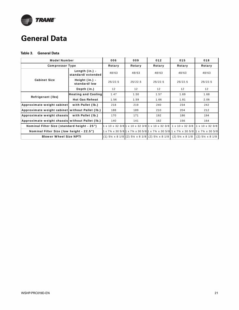
Table 3. General Data
Model Number 006 009 012 015 018
Compressor Type Rotary Rotary Rotary Rotary Rotary
Cabinet Size
Length (in.) - standard/extended 48/63 48/63 48/63 48/63 48/63
Height (in.) - standard/low 25/22.5 25/22.5 25/22.5 25/22.5 25/22.5
Depth (in.) 12 12 12 12 12
Refrigerant (lbs)Heating and Cooling 1.47 1.50 1.57 1.69 1.68
Hot Gas Reheat 1.56 1.59 1.66 1.81 2.06
Approximate weight cabinet with Pallet (lb.) 218 219 240 234 242
Approximate weight cabinet without Pallet (lb.) 188 189 210 204 212
Approximate weight chassis with Pallet (lb.) 170 171 192 186 194
Approximate weight chassis without Pallet (lb.) 140 141 162 156 164
Nominal Filter Size (standard height - 25”) 1 x 10 x 32 3/8 1 x 10 x 32 3/8 1 x 10 x 32 3/8 1 x 10 x 32 3/8 1 x 10 x 32 3/8
Nominal Filter Size (low height - 22.5”) 1 x 7¾ x 30 5/8 1 x 7¾ x 30 5/8 1 x 7¾ x 30 5/8 1 x 7¾ x 30 5/8 1 x 7¾ x 30 5/8
Blower Wheel Size NPTI (1) 5¼ x 8 1/8 (2) 5¼ x 8 1/8 (2) 5¼ x 8 1/8 (2) 5¼ x 8 1/8 (2) 5¼ x 8 1/8
Performance Data
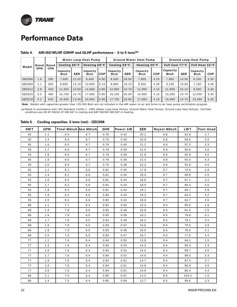
Table 4. ARI-ISO WLHP, GWHP and GLHP performance - .5 to 5 tons(a)
Model Rated GPM
Rated CFM
Water Loop Heat Pump Ground Water Heat Pump Ground Loop Heat Pump
Cooling 86°F Heating 68°F Cooling 59°F Heating 50°F Full Cool 77°F Full Heat 32°F
Capacity Btuh EER
Capacity Btuh COP
Capacity Btuh EER
Capacity Btuh COP
Capacity Btuh EER
Capacity Btuh COP
GEC006 1.8 290 7,500 12.50 9,400 4.90 8,500 18.50 7,900 4.20 7,800 14.50 6,100 3.30
GEC009 2.1 305 8,800 13.10 10,900 5.10 9,900 18.10 9,500 4.30 9,100 14.60 7,100 3.40
GEC012 2.8 430 11,500 13.50 14,600 4.90 12,800 19.70 11,900 4.10 11,900 15.10 9,500 3.40
GEC015 3.5 480 14,700 13.70 17,900 4.80 16,100 20.00 14,800 4.10 15,300 15.70 12,000 3.40
GEC018 4.2 530 16,500 13.40 20,800 4.80 17,700 18.90 17,000 4.10 16,900 14.70 13,400 3.30
Note: Models with capacities greater than 135,000 Btuh are not included in the ARI water-to-air and brine-to-air heat pump certification program.
(a)Rated in accordance with ISO Standard 13256-1: 1998 (Water Loop Heat Pumps, Ground Water Heat Pumps, Ground Loop Heat Pumps). Certified conditions are 80.6F DB/66.2F WB EAT in cooling and 68F DB/59F WB EAT in heating.
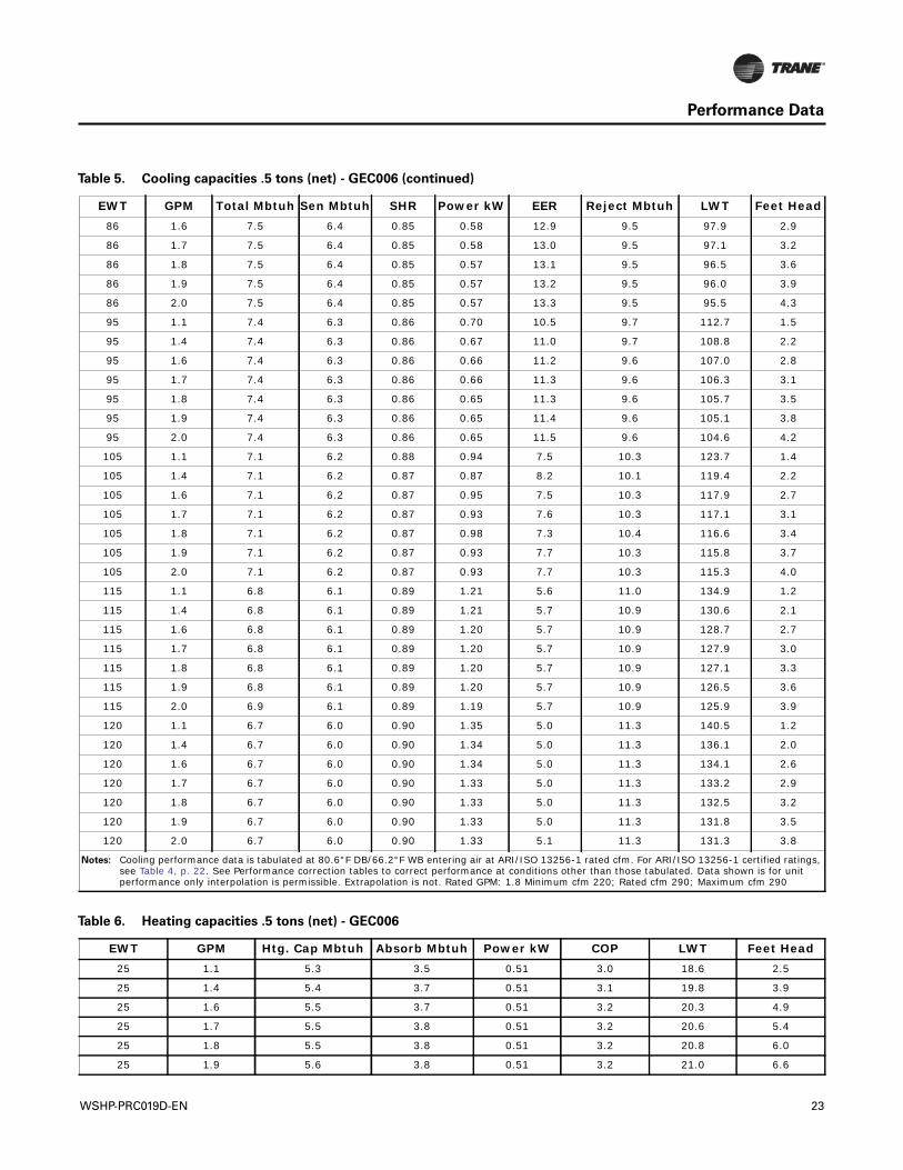
Table 5. Cooling capacities .5 tons (net) - GEC006
EWT GPM Total Mbtuh Sen Mbtuh SHR Power kW EER Reject Mbtuh LWT Feet Head45 1.1 8.4 6.7 0.79 0.42 20.2 9.8 62.8 1.7
45 1.4 8.4 6.7 0.79 0.40 20.9 9.8 59.0 2.6
45 1.6 8.5 6.7 0.79 0.40 21.2 9.9 57.3 3.3
45 1.7 8.5 6.7 0.79 0.39 21.5 9.8 56.6 3.6
45 1.8 8.5 6.7 0.79 0.39 21.8 9.8 55.9 4.0
45 1.9 8.5 6.7 0.79 0.39 22.0 9.8 55.4 4.3
45 2.0 8.5 6.7 0.79 0.38 22.3 9.8 54.8 4.6
55 1.1 8.1 6.6 0.81 0.45 17.8 9.7 72.6 1.6
55 1.4 8.2 6.6 0.81 0.44 18.4 9.7 68.8 2.6
55 1.6 8.2 6.6 0.81 0.44 18.8 9.7 67.1 3.2
55 1.7 8.2 6.6 0.81 0.43 18.9 9.7 66.4 3.6
55 1.8 8.2 6.6 0.81 0.43 19.1 9.7 65.7 3.9
55 1.9 8.2 6.6 0.80 0.43 19.3 9.7 65.2 4.2
55 2.0 8.2 6.6 0.80 0.42 19.6 9.7 64.7 4.5
68 1.1 7.7 6.4 0.84 0.50 15.3 9.4 85.0 1.6
68 1.4 7.8 6.5 0.83 0.49 15.8 9.5 81.5 2.5
68 1.6 7.8 6.5 0.83 0.49 16.1 9.5 79.8 3.1
68 1.7 7.8 6.5 0.83 0.48 16.2 9.5 79.1 3.5
68 1.8 7.8 6.5 0.83 0.47 16.6 9.4 78.5 3.8
68 1.9 7.9 6.5 0.83 0.48 16.5 9.5 78.0 4.1
68 2.0 7.9 6.5 0.83 0.47 16.7 9.5 77.5 4.4
77 1.1 7.6 6.4 0.84 0.55 13.8 9.4 94.1 1.5
77 1.4 7.6 6.4 0.84 0.53 14.3 9.4 90.4 2.4
77 1.6 7.6 6.4 0.84 0.52 14.5 9.4 88.7 3.0
77 1.7 7.6 6.4 0.84 0.52 14.6 9.4 88.0 3.3
77 1.8 7.6 6.4 0.84 0.52 14.7 9.4 87.4 3.7
77 1.9 7.6 6.4 0.84 0.51 14.8 9.4 86.9 4.0
77 2.0 7.6 6.4 0.84 0.51 14.9 9.4 86.4 4.4
86 1.1 7.5 6.4 0.85 0.61 12.2 9.6 103.4 1.5
86 1.4 7.5 6.4 0.85 0.59 12.7 9.5 99.6 2.3
22 WSHP-PRC019D-EN
Performance Data
86 1.6 7.5 6.4 0.85 0.58 12.9 9.5 97.9 2.9
86 1.7 7.5 6.4 0.85 0.58 13.0 9.5 97.1 3.2
86 1.8 7.5 6.4 0.85 0.57 13.1 9.5 96.5 3.6
86 1.9 7.5 6.4 0.85 0.57 13.2 9.5 96.0 3.9
86 2.0 7.5 6.4 0.85 0.57 13.3 9.5 95.5 4.3
95 1.1 7.4 6.3 0.86 0.70 10.5 9.7 112.7 1.5
95 1.4 7.4 6.3 0.86 0.67 11.0 9.7 108.8 2.2
95 1.6 7.4 6.3 0.86 0.66 11.2 9.6 107.0 2.8
95 1.7 7.4 6.3 0.86 0.66 11.3 9.6 106.3 3.1
95 1.8 7.4 6.3 0.86 0.65 11.3 9.6 105.7 3.5
95 1.9 7.4 6.3 0.86 0.65 11.4 9.6 105.1 3.8
95 2.0 7.4 6.3 0.86 0.65 11.5 9.6 104.6 4.2
105 1.1 7.1 6.2 0.88 0.94 7.5 10.3 123.7 1.4
105 1.4 7.1 6.2 0.87 0.87 8.2 10.1 119.4 2.2
105 1.6 7.1 6.2 0.87 0.95 7.5 10.3 117.9 2.7
105 1.7 7.1 6.2 0.87 0.93 7.6 10.3 117.1 3.1
105 1.8 7.1 6.2 0.87 0.98 7.3 10.4 116.6 3.4
105 1.9 7.1 6.2 0.87 0.93 7.7 10.3 115.8 3.7
105 2.0 7.1 6.2 0.87 0.93 7.7 10.3 115.3 4.0
115 1.1 6.8 6.1 0.89 1.21 5.6 11.0 134.9 1.2
115 1.4 6.8 6.1 0.89 1.21 5.7 10.9 130.6 2.1
115 1.6 6.8 6.1 0.89 1.20 5.7 10.9 128.7 2.7
115 1.7 6.8 6.1 0.89 1.20 5.7 10.9 127.9 3.0
115 1.8 6.8 6.1 0.89 1.20 5.7 10.9 127.1 3.3
115 1.9 6.8 6.1 0.89 1.20 5.7 10.9 126.5 3.6
115 2.0 6.9 6.1 0.89 1.19 5.7 10.9 125.9 3.9
120 1.1 6.7 6.0 0.90 1.35 5.0 11.3 140.5 1.2
120 1.4 6.7 6.0 0.90 1.34 5.0 11.3 136.1 2.0
120 1.6 6.7 6.0 0.90 1.34 5.0 11.3 134.1 2.6
120 1.7 6.7 6.0 0.90 1.33 5.0 11.3 133.2 2.9
120 1.8 6.7 6.0 0.90 1.33 5.0 11.3 132.5 3.2
120 1.9 6.7 6.0 0.90 1.33 5.0 11.3 131.8 3.5
120 2.0 6.7 6.0 0.90 1.33 5.1 11.3 131.3 3.8
Notes: Cooling performance data is tabulated at 80.6°F DB/66.2°F WB entering air at ARI/ISO 13256-1 rated cfm. For ARI/ISO 13256-1 certified ratings, see Table 4, p. 22. See Performance correction tables to correct performance at conditions other than those tabulated. Data shown is for unit performance only interpolation is permissible. Extrapolation is not. Rated GPM: 1.8 Minimum cfm 220; Rated cfm 290; Maximum cfm 290
Table 5. Cooling capacities .5 tons (net) - GEC006 (continued)
EWT GPM Total Mbtuh Sen Mbtuh SHR Power kW EER Reject Mbtuh LWT Feet Head
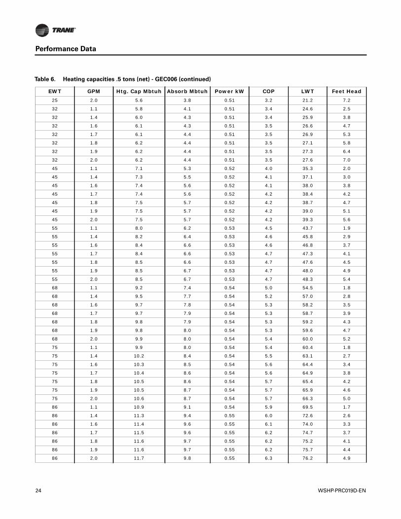
Table 6. Heating capacities .5 tons (net) - GEC006
EWT GPM Htg. Cap Mbtuh Absorb Mbtuh Power kW COP LWT Feet Head25 1.1 5.3 3.5 0.51 3.0 18.6 2.5
25 1.4 5.4 3.7 0.51 3.1 19.8 3.9
25 1.6 5.5 3.7 0.51 3.2 20.3 4.9
25 1.7 5.5 3.8 0.51 3.2 20.6 5.4
25 1.8 5.5 3.8 0.51 3.2 20.8 6.0
25 1.9 5.6 3.8 0.51 3.2 21.0 6.6
WSHP-PRC019D-EN 23
Performance Data
25 2.0 5.6 3.8 0.51 3.2 21.2 7.2
32 1.1 5.8 4.1 0.51 3.4 24.6 2.5
32 1.4 6.0 4.3 0.51 3.4 25.9 3.8
32 1.6 6.1 4.3 0.51 3.5 26.6 4.7
32 1.7 6.1 4.4 0.51 3.5 26.9 5.3
32 1.8 6.2 4.4 0.51 3.5 27.1 5.8
32 1.9 6.2 4.4 0.51 3.5 27.3 6.4
32 2.0 6.2 4.4 0.51 3.5 27.6 7.0
45 1.1 7.1 5.3 0.52 4.0 35.3 2.0
45 1.4 7.3 5.5 0.52 4.1 37.1 3.0
45 1.6 7.4 5.6 0.52 4.1 38.0 3.8
45 1.7 7.4 5.6 0.52 4.2 38.4 4.2
45 1.8 7.5 5.7 0.52 4.2 38.7 4.7
45 1.9 7.5 5.7 0.52 4.2 39.0 5.1
45 2.0 7.5 5.7 0.52 4.2 39.3 5.6
55 1.1 8.0 6.2 0.53 4.5 43.7 1.9
55 1.4 8.2 6.4 0.53 4.6 45.8 2.9
55 1.6 8.4 6.6 0.53 4.6 46.8 3.7
55 1.7 8.4 6.6 0.53 4.7 47.3 4.1
55 1.8 8.5 6.6 0.53 4.7 47.6 4.5
55 1.9 8.5 6.7 0.53 4.7 48.0 4.9
55 2.0 8.5 6.7 0.53 4.7 48.3 5.4
68 1.1 9.2 7.4 0.54 5.0 54.5 1.8
68 1.4 9.5 7.7 0.54 5.2 57.0 2.8
68 1.6 9.7 7.8 0.54 5.3 58.2 3.5
68 1.7 9.7 7.9 0.54 5.3 58.7 3.9
68 1.8 9.8 7.9 0.54 5.3 59.2 4.3
68 1.9 9.8 8.0 0.54 5.3 59.6 4.7
68 2.0 9.9 8.0 0.54 5.4 60.0 5.2
75 1.1 9.9 8.0 0.54 5.4 60.4 1.8
75 1.4 10.2 8.4 0.54 5.5 63.1 2.7
75 1.6 10.3 8.5 0.54 5.6 64.4 3.4
75 1.7 10.4 8.6 0.54 5.6 64.9 3.8
75 1.8 10.5 8.6 0.54 5.7 65.4 4.2
75 1.9 10.5 8.7 0.54 5.7 65.9 4.6
75 2.0 10.6 8.7 0.54 5.7 66.3 5.0
86 1.1 10.9 9.1 0.54 5.9 69.5 1.7
86 1.4 11.3 9.4 0.55 6.0 72.6 2.6
86 1.6 11.4 9.6 0.55 6.1 74.0 3.3
86 1.7 11.5 9.6 0.55 6.2 74.7 3.7
86 1.8 11.6 9.7 0.55 6.2 75.2 4.1
86 1.9 11.6 9.7 0.55 6.2 75.7 4.4
86 2.0 11.7 9.8 0.55 6.3 76.2 4.9
Table 6. Heating capacities .5 tons (net) - GEC006 (continued)
EWT GPM Htg. Cap Mbtuh Absorb Mbtuh Power kW COP LWT Feet Head
24 WSHP-PRC019D-EN
Performance Data
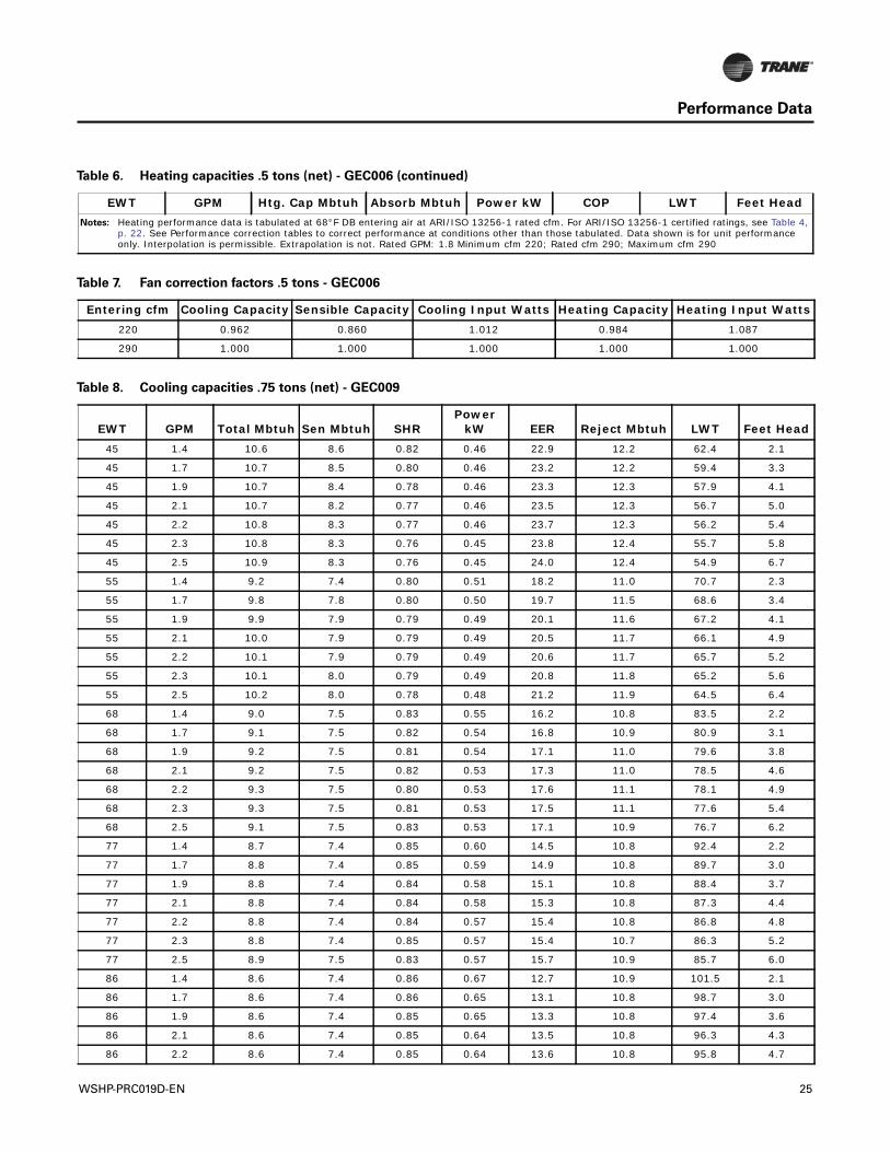
Notes: Heating performance data is tabulated at 68°F DB entering air at ARI/ISO 13256-1 rated cfm. For ARI/ISO 13256-1 certified ratings, see Table 4, p. 22. See Performance correction tables to correct performance at conditions other than those tabulated. Data shown is for unit performance only. Interpolation is permissible. Extrapolation is not. Rated GPM: 1.8 Minimum cfm 220; Rated cfm 290; Maximum cfm 290
Table 6. Heating capacities .5 tons (net) - GEC006 (continued)
EWT GPM Htg. Cap Mbtuh Absorb Mbtuh Power kW COP LWT Feet Head
Table 7. Fan correction factors .5 tons - GEC006
Entering cfm Cooling Capacity Sensible Capacity Cooling Input Watts Heating Capacity Heating Input Watts220 0.962 0.860 1.012 0.984 1.087
290 1.000 1.000 1.000 1.000 1.000
Table 8. Cooling capacities .75 tons (net) - GEC009
EWT GPM Total Mbtuh Sen Mbtuh SHRPower
kW EER Reject Mbtuh LWT Feet Head45 1.4 10.6 8.6 0.82 0.46 22.9 12.2 62.4 2.1
45 1.7 10.7 8.5 0.80 0.46 23.2 12.2 59.4 3.3
45 1.9 10.7 8.4 0.78 0.46 23.3 12.3 57.9 4.1
45 2.1 10.7 8.2 0.77 0.46 23.5 12.3 56.7 5.0
45 2.2 10.8 8.3 0.77 0.46 23.7 12.3 56.2 5.4
45 2.3 10.8 8.3 0.76 0.45 23.8 12.4 55.7 5.8
45 2.5 10.9 8.3 0.76 0.45 24.0 12.4 54.9 6.7
55 1.4 9.2 7.4 0.80 0.51 18.2 11.0 70.7 2.3
55 1.7 9.8 7.8 0.80 0.50 19.7 11.5 68.6 3.4
55 1.9 9.9 7.9 0.79 0.49 20.1 11.6 67.2 4.1
55 2.1 10.0 7.9 0.79 0.49 20.5 11.7 66.1 4.9
55 2.2 10.1 7.9 0.79 0.49 20.6 11.7 65.7 5.2
55 2.3 10.1 8.0 0.79 0.49 20.8 11.8 65.2 5.6
55 2.5 10.2 8.0 0.78 0.48 21.2 11.9 64.5 6.4
68 1.4 9.0 7.5 0.83 0.55 16.2 10.8 83.5 2.2
68 1.7 9.1 7.5 0.82 0.54 16.8 10.9 80.9 3.1
68 1.9 9.2 7.5 0.81 0.54 17.1 11.0 79.6 3.8
68 2.1 9.2 7.5 0.82 0.53 17.3 11.0 78.5 4.6
68 2.2 9.3 7.5 0.80 0.53 17.6 11.1 78.1 4.9
68 2.3 9.3 7.5 0.81 0.53 17.5 11.1 77.6 5.4
68 2.5 9.1 7.5 0.83 0.53 17.1 10.9 76.7 6.2
77 1.4 8.7 7.4 0.85 0.60 14.5 10.8 92.4 2.2
77 1.7 8.8 7.4 0.85 0.59 14.9 10.8 89.7 3.0
77 1.9 8.8 7.4 0.84 0.58 15.1 10.8 88.4 3.7
77 2.1 8.8 7.4 0.84 0.58 15.3 10.8 87.3 4.4
77 2.2 8.8 7.4 0.84 0.57 15.4 10.8 86.8 4.8
77 2.3 8.8 7.4 0.85 0.57 15.4 10.7 86.3 5.2
77 2.5 8.9 7.5 0.83 0.57 15.7 10.9 85.7 6.0
86 1.4 8.6 7.4 0.86 0.67 12.7 10.9 101.5 2.1
86 1.7 8.6 7.4 0.86 0.65 13.1 10.8 98.7 3.0
86 1.9 8.6 7.4 0.85 0.65 13.3 10.8 97.4 3.6
86 2.1 8.6 7.4 0.85 0.64 13.5 10.8 96.3 4.3
86 2.2 8.6 7.4 0.85 0.64 13.6 10.8 95.8 4.7
WSHP-PRC019D-EN 25
Performance Data
86 2.3 8.6 7.4 0.85 0.64 13.6 10.8 95.4 5.1
86 2.5 8.7 7.4 0.85 0.63 13.7 10.8 94.7 5.9
95 1.4 8.4 7.3 0.87 0.78 10.9 11.1 110.9 2.0
95 1.7 8.5 7.3 0.86 0.76 11.1 11.1 108.0 2.9
95 1.9 8.5 7.3 0.86 0.75 11.3 11.0 106.6 3.5
95 2.1 8.4 7.3 0.86 0.73 11.5 10.9 105.4 4.2
95 2.2 8.5 7.3 0.86 0.74 11.4 11.0 105.0 4.5
95 2.3 8.4 7.3 0.87 0.72 11.7 10.9 104.5 4.9
95 2.5 8.4 7.3 0.87 0.72 11.8 10.9 103.7 5.7
105 1.4 8.5 7.3 0.86 1.06 8.0 12.1 122.3 2.0
105 1.7 8.4 7.3 0.87 0.94 8.9 11.6 118.6 2.9
105 1.9 8.4 7.3 0.87 0.93 9.0 11.5 117.1 3.5
105 2.1 8.4 7.3 0.87 0.91 9.2 11.5 115.9 4.2
105 2.2 8.4 7.3 0.87 0.90 9.2 11.4 115.4 4.5
105 2.3 8.4 7.3 0.87 0.90 9.3 11.4 114.9 4.9
105 2.5 8.4 7.3 0.87 0.88 9.5 11.4 114.1 5.5
115 1.4 8.2 7.2 0.88 1.12 7.3 12.1 132.2 1.8
115 1.7 8.2 7.2 0.88 1.10 7.5 12.0 129.1 2.8
115 1.9 8.2 7.2 0.88 1.08 7.6 11.9 127.6 3.5
115 2.1 8.2 7.2 0.88 1.07 7.7 11.9 126.3 4.1
115 2.2 8.2 7.2 0.88 1.06 7.8 11.8 125.8 4.5
115 2.3 8.2 7.2 0.88 1.05 7.8 11.8 125.3 4.8
115 2.5 8.2 7.2 0.88 1.03 8.0 11.8 124.4 5.5
120 1.4 8.2 7.2 0.88 1.20 6.8 12.3 137.5 1.8
120 1.7 8.2 7.2 0.88 1.17 7.0 12.2 134.3 2.8
120 1.9 8.2 7.2 0.88 1.16 7.1 12.1 132.8 3.4
120 2.1 8.2 7.2 0.88 1.14 7.2 12.1 131.5 4.1
120 2.2 8.2 7.2 0.88 1.13 7.2 12.0 130.9 4.4
120 2.3 8.2 7.2 0.88 1.13 7.3 12.0 130.4 4.8
120 2.5 8.2 7.2 0.88 1.11 7.4 12.0 129.6 5.4
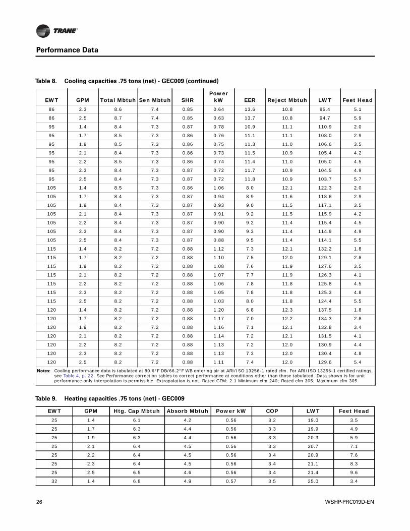
Notes: Cooling performance data is tabulated at 80.6°F DB/66.2°F WB entering air at ARI/ISO 13256-1 rated cfm. For ARI/ISO 13256-1 certified ratings, see Table 4, p. 22. See Performance correction tables to correct performance at conditions other than those tabulated. Data shown is for unit performance only interpolation is permissible. Extrapolation is not. Rated GPM: 2.1 Minimum cfm 240; Rated cfm 305; Maximum cfm 305
Table 8. Cooling capacities .75 tons (net) - GEC009 (continued)
EWT GPM Total Mbtuh Sen Mbtuh SHRPower
kW EER Reject Mbtuh LWT Feet Head
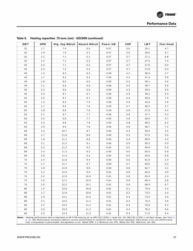
Table 9. Heating capacities .75 tons (net) - GEC009
EWT GPM Htg. Cap Mbtuh Absorb Mbtuh Power kW COP LWT Feet Head25 1.4 6.1 4.2 0.56 3.2 19.0 3.5
25 1.7 6.3 4.4 0.56 3.3 19.9 4.9
25 1.9 6.3 4.4 0.56 3.3 20.3 5.9
25 2.1 6.4 4.5 0.56 3.3 20.7 7.1
25 2.2 6.4 4.5 0.56 3.4 20.9 7.6
25 2.3 6.4 4.5 0.56 3.4 21.1 8.3
25 2.5 6.5 4.6 0.56 3.4 21.4 9.6
32 1.4 6.8 4.9 0.57 3.5 25.0 3.4
26 WSHP-PRC019D-EN
Performance Data
32 1.7 7.0 5.0 0.57 3.6 26.1 4.7
32 1.9 7.0 5.1 0.57 3.6 26.6 5.7
32 2.1 7.1 5.1 0.57 3.7 27.1 6.8
32 2.2 7.1 5.2 0.57 3.7 27.3 7.4
32 2.3 7.1 5.2 0.57 3.7 27.5 8.0
32 2.5 7.2 5.2 0.57 3.7 27.8 9.3
45 1.4 8.3 6.3 0.58 4.2 36.0 2.7
45 1.7 8.4 6.4 0.58 4.2 37.4 3.8
45 1.9 8.5 6.5 0.58 4.3 38.1 4.6
45 2.1 8.6 6.6 0.58 4.3 38.7 5.5
45 2.2 8.6 6.6 0.59 4.3 39.0 6.0
45 2.3 8.7 6.7 0.58 4.3 39.2 6.4
45 2.5 8.7 6.7 0.59 4.4 39.6 7.5
55 1.4 9.3 7.3 0.59 4.6 44.6 2.6
55 1.7 9.5 7.5 0.59 4.7 46.2 3.7
55 1.9 9.6 7.6 0.59 4.8 47.0 4.4
55 2.1 9.7 7.7 0.59 4.8 47.7 5.3
55 2.2 9.8 7.7 0.59 4.8 48.0 5.7
55 2.3 9.8 7.8 0.59 4.8 48.2 6.2
55 2.5 9.9 7.8 0.59 4.9 48.7 7.2
68 1.4 10.7 8.7 0.60 5.3 55.6 2.5
68 1.7 11.0 8.9 0.60 5.4 57.5 3.5
68 1.9 11.1 9.0 0.60 5.4 58.5 4.2
68 2.1 11.2 9.1 0.60 5.5 59.3 5.0
68 2.2 11.2 9.2 0.60 5.5 59.6 5.5
68 2.3 11.3 9.2 0.60 5.5 60.0 5.9
68 2.5 11.4 9.3 0.60 5.5 60.6 6.8
75 1.4 11.5 9.4 0.60 5.6 61.5 2.4
75 1.7 11.7 9.7 0.60 5.7 63.6 3.4
75 1.9 11.9 9.8 0.60 5.8 64.7 4.1
75 2.1 12.0 9.9 0.61 5.8 65.6 4.9
75 2.2 12.0 10.0 0.61 5.8 65.9 5.3
75 2.3 12.1 10.0 0.61 5.8 66.3 5.8
75 2.5 12.2 10.1 0.61 5.9 66.9 6.7
86 1.4 12.6 10.6 0.61 6.1 70.9 2.4
86 1.7 12.9 10.8 0.61 6.2 73.2 3.3
86 1.9 13.1 11.0 0.61 6.3 74.4 4.0
86 2.1 13.2 11.1 0.61 6.3 75.4 4.8
86 2.2 13.2 11.2 0.61 6.3 75.9 5.2
86 2.3 13.3 11.2 0.61 6.4 76.3 5.6
86 2.5 13.4 11.3 0.61 6.4 77.0 6.4
Notes: Heating performance data is tabulated at 68°F DB entering air at ARI/ISO 13256-1 rated cfm. For ARI/ISO 13256-1 certified ratings, see Table 4, p. 22. See Performance correction tables to correct performance at conditions other than those tabulated. Data shown is for unit performance only. Interpolation is permissible. Extrapolation is not. Rated GPM: 2.1 Minimum cfm 240; Rated cfm 305; Maximum cfm 305
Table 9. Heating capacities .75 tons (net) - GEC009 (continued)
EWT GPM Htg. Cap Mbtuh Absorb Mbtuh Power kW COP LWT Feet Head
WSHP-PRC019D-EN 27
Performance Data
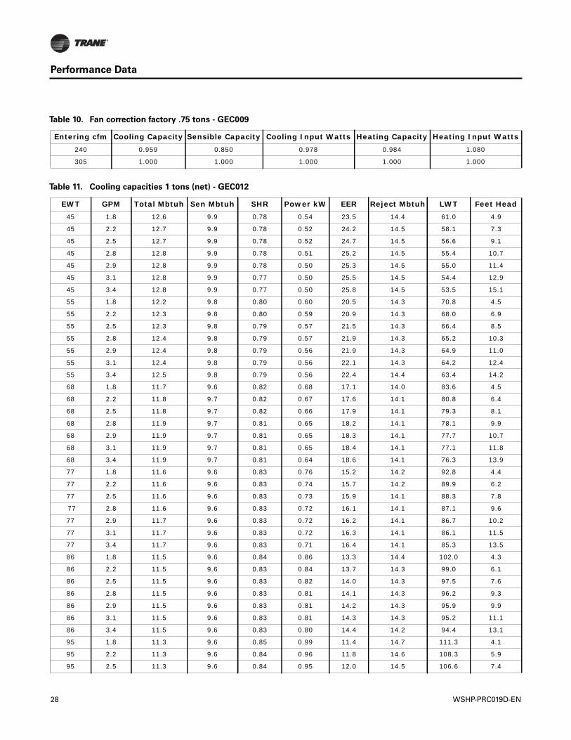
Table 10. Fan correction factory .75 tons - GEC009
Entering cfm Cooling Capacity Sensible Capacity Cooling Input Watts Heating Capacity Heating Input Watts240 0.959 0.850 0.978 0.984 1.080
305 1.000 1.000 1.000 1.000 1.000
Table 11. Cooling capacities 1 tons (net) - GEC012
EWT GPM Total Mbtuh Sen Mbtuh SHR Power kW EER Reject Mbtuh LWT Feet Head45 1.8 12.6 9.9 0.78 0.54 23.5 14.4 61.0 4.9
45 2.2 12.7 9.9 0.78 0.52 24.2 14.5 58.1 7.3
45 2.5 12.7 9.9 0.78 0.52 24.7 14.5 56.6 9.1
45 2.8 12.8 9.9 0.78 0.51 25.2 14.5 55.4 10.7
45 2.9 12.8 9.9 0.78 0.50 25.3 14.5 55.0 11.4
45 3.1 12.8 9.9 0.77 0.50 25.5 14.5 54.4 12.9
45 3.4 12.8 9.9 0.77 0.50 25.8 14.5 53.5 15.1
55 1.8 12.2 9.8 0.80 0.60 20.5 14.3 70.8 4.5
55 2.2 12.3 9.8 0.80 0.59 20.9 14.3 68.0 6.9
55 2.5 12.3 9.8 0.79 0.57 21.5 14.3 66.4 8.5
55 2.8 12.4 9.8 0.79 0.57 21.9 14.3 65.2 10.3
55 2.9 12.4 9.8 0.79 0.56 21.9 14.3 64.9 11.0
55 3.1 12.4 9.8 0.79 0.56 22.1 14.3 64.2 12.4
55 3.4 12.5 9.8 0.79 0.56 22.4 14.4 63.4 14.2
68 1.8 11.7 9.6 0.82 0.68 17.1 14.0 83.6 4.5
68 2.2 11.8 9.7 0.82 0.67 17.6 14.1 80.8 6.4
68 2.5 11.8 9.7 0.82 0.66 17.9 14.1 79.3 8.1
68 2.8 11.9 9.7 0.81 0.65 18.2 14.1 78.1 9.9
68 2.9 11.9 9.7 0.81 0.65 18.3 14.1 77.7 10.7
68 3.1 11.9 9.7 0.81 0.65 18.4 14.1 77.1 11.8
68 3.4 11.9 9.7 0.81 0.64 18.6 14.1 76.3 13.9
77 1.8 11.6 9.6 0.83 0.76 15.2 14.2 92.8 4.4
77 2.2 11.6 9.6 0.83 0.74 15.7 14.2 89.9 6.2
77 2.5 11.6 9.6 0.83 0.73 15.9 14.1 88.3 7.8
77 2.8 11.6 9.6 0.83 0.72 16.1 14.1 87.1 9.6
77 2.9 11.7 9.6 0.83 0.72 16.2 14.1 86.7 10.2
77 3.1 11.7 9.6 0.83 0.72 16.3 14.1 86.1 11.5
77 3.4 11.7 9.6 0.83 0.71 16.4 14.1 85.3 13.5
86 1.8 11.5 9.6 0.84 0.86 13.3 14.4 102.0 4.3
86 2.2 11.5 9.6 0.83 0.84 13.7 14.3 99.0 6.1
86 2.5 11.5 9.6 0.83 0.82 14.0 14.3 97.5 7.6
86 2.8 11.5 9.6 0.83 0.81 14.1 14.3 96.2 9.3
86 2.9 11.5 9.6 0.83 0.81 14.2 14.3 95.9 9.9
86 3.1 11.5 9.6 0.83 0.81 14.3 14.3 95.2 11.1
86 3.4 11.5 9.6 0.83 0.80 14.4 14.2 94.4 13.1
95 1.8 11.3 9.6 0.85 0.99 11.4 14.7 111.3 4.1
95 2.2 11.3 9.6 0.84 0.96 11.8 14.6 108.3 5.9
95 2.5 11.3 9.6 0.84 0.95 12.0 14.5 106.6 7.4
28 WSHP-PRC019D-EN
Performance Data
95 2.8 11.3 9.6 0.84 0.93 12.1 14.5 105.4 9.1
95 2.9 11.3 9.6 0.84 0.93 12.1 14.5 105.0 9.6
95 3.1 11.3 9.6 0.84 0.93 12.2 14.5 104.3 10.8
95 3.4 11.3 9.6 0.84 0.92 12.3 14.5 103.5 12.7
105 1.8 11.0 9.5 0.86 1.23 8.9 15.2 121.9 4.0
105 2.2 11.0 9.5 0.86 1.20 9.2 15.1 118.7 5.7
105 2.5 11.0 9.5 0.86 1.18 9.3 15.0 117.0 7.2
105 2.8 11.0 9.5 0.87 1.16 9.4 14.9 115.7 8.8
105 2.9 11.0 9.5 0.87 1.16 9.5 14.9 115.3 9.4
105 3.1 11.0 9.5 0.86 1.15 9.5 14.9 114.6 10.5
105 3.4 11.0 9.5 0.86 1.14 9.6 14.9 113.7 12.4
115 1.8 10.6 9.4 0.89 1.45 7.3 15.6 132.3 3.5
115 2.2 10.6 9.4 0.89 1.43 7.4 15.5 129.1 5.6
115 2.5 10.6 9.4 0.89 1.41 7.5 15.5 127.4 7.2
115 2.8 10.6 9.4 0.89 1.40 7.6 15.4 126.0 8.7
115 2.9 10.6 9.4 0.89 1.39 7.6 15.4 125.6 9.3
115 3.1 10.6 9.4 0.89 1.38 7.7 15.4 124.9 10.3
115 3.4 10.6 9.4 0.89 1.37 7.8 15.3 124.0 11.9
120 1.8 10.5 9.4 0.90 1.57 6.7 15.8 137.6 3.3
120 2.2 10.5 9.4 0.90 1.55 6.8 15.7 134.3 5.4
120 2.5 10.5 9.4 0.90 1.53 6.8 15.7 132.6 7.0
120 2.8 10.5 9.4 0.90 1.52 6.9 15.6 131.2 8.6
120 2.9 10.5 9.4 0.90 1.51 6.9 15.6 130.8 9.1
120 3.1 10.5 9.4 0.90 1.50 7.0 15.6 130.1 10.2
120 3.4 10.5 9.4 0.90 1.49 7.0 15.5 129.1 11.8
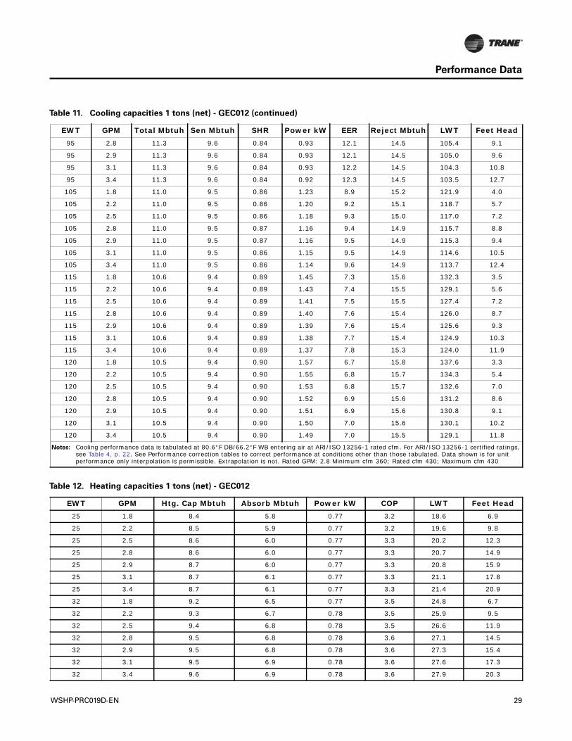
Notes: Cooling performance data is tabulated at 80.6°F DB/66.2°F WB entering air at ARI/ISO 13256-1 rated cfm. For ARI/ISO 13256-1 certified ratings, see Table 4, p. 22. See Performance correction tables to correct performance at conditions other than those tabulated. Data shown is for unit performance only interpolation is permissible. Extrapolation is not. Rated GPM: 2.8 Minimum cfm 360; Rated cfm 430; Maximum cfm 430
Table 11. Cooling capacities 1 tons (net) - GEC012 (continued)
EWT GPM Total Mbtuh Sen Mbtuh SHR Power kW EER Reject Mbtuh LWT Feet Head
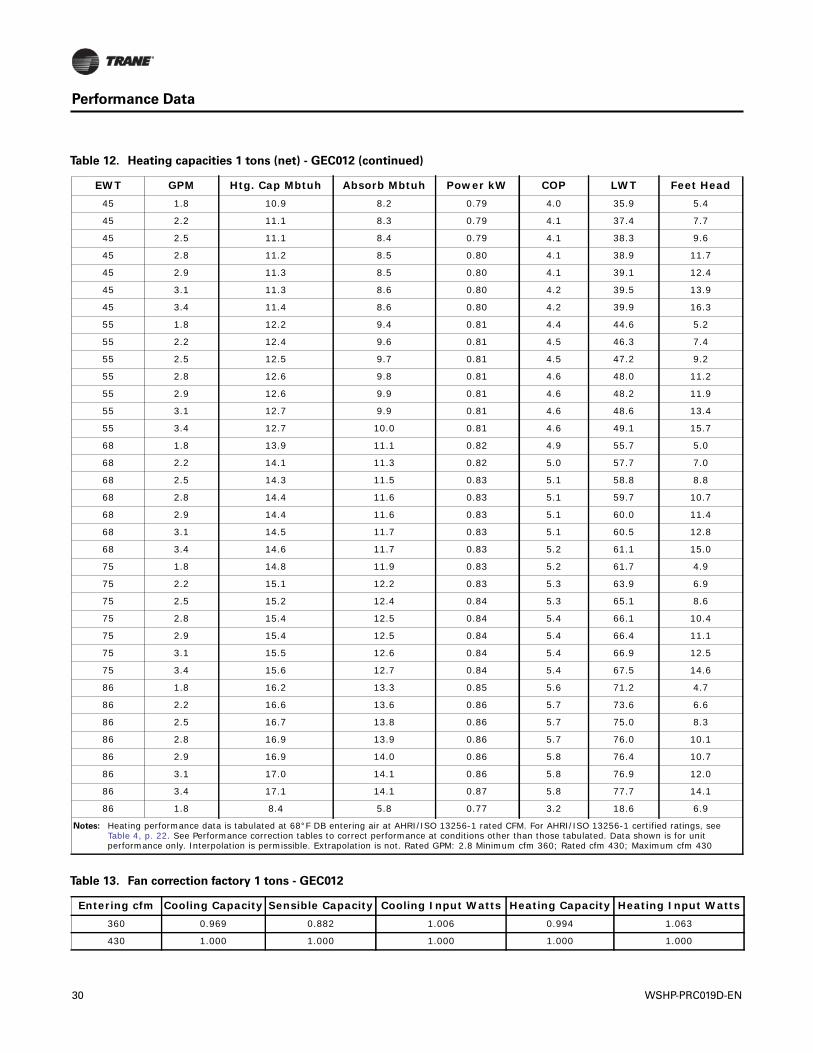
Table 12. Heating capacities 1 tons (net) - GEC012
EWT GPM Htg. Cap Mbtuh Absorb Mbtuh Power kW COP LWT Feet Head25 1.8 8.4 5.8 0.77 3.2 18.6 6.9
25 2.2 8.5 5.9 0.77 3.2 19.6 9.8
25 2.5 8.6 6.0 0.77 3.3 20.2 12.3
25 2.8 8.6 6.0 0.77 3.3 20.7 14.9
25 2.9 8.7 6.0 0.77 3.3 20.8 15.9
25 3.1 8.7 6.1 0.77 3.3 21.1 17.8
25 3.4 8.7 6.1 0.77 3.3 21.4 20.9
32 1.8 9.2 6.5 0.77 3.5 24.8 6.7
32 2.2 9.3 6.7 0.78 3.5 25.9 9.5
32 2.5 9.4 6.8 0.78 3.5 26.6 11.9
32 2.8 9.5 6.8 0.78 3.6 27.1 14.5
32 2.9 9.5 6.8 0.78 3.6 27.3 15.4
32 3.1 9.5 6.9 0.78 3.6 27.6 17.3
32 3.4 9.6 6.9 0.78 3.6 27.9 20.3
WSHP-PRC019D-EN 29
Performance Data
45 1.8 10.9 8.2 0.79 4.0 35.9 5.4
45 2.2 11.1 8.3 0.79 4.1 37.4 7.7
45 2.5 11.1 8.4 0.79 4.1 38.3 9.6
45 2.8 11.2 8.5 0.80 4.1 38.9 11.7
45 2.9 11.3 8.5 0.80 4.1 39.1 12.4
45 3.1 11.3 8.6 0.80 4.2 39.5 13.9
45 3.4 11.4 8.6 0.80 4.2 39.9 16.3
55 1.8 12.2 9.4 0.81 4.4 44.6 5.2
55 2.2 12.4 9.6 0.81 4.5 46.3 7.4
55 2.5 12.5 9.7 0.81 4.5 47.2 9.2
55 2.8 12.6 9.8 0.81 4.6 48.0 11.2
55 2.9 12.6 9.9 0.81 4.6 48.2 11.9
55 3.1 12.7 9.9 0.81 4.6 48.6 13.4
55 3.4 12.7 10.0 0.81 4.6 49.1 15.7
68 1.8 13.9 11.1 0.82 4.9 55.7 5.0
68 2.2 14.1 11.3 0.82 5.0 57.7 7.0
68 2.5 14.3 11.5 0.83 5.1 58.8 8.8
68 2.8 14.4 11.6 0.83 5.1 59.7 10.7
68 2.9 14.4 11.6 0.83 5.1 60.0 11.4
68 3.1 14.5 11.7 0.83 5.1 60.5 12.8
68 3.4 14.6 11.7 0.83 5.2 61.1 15.0
75 1.8 14.8 11.9 0.83 5.2 61.7 4.9
75 2.2 15.1 12.2 0.83 5.3 63.9 6.9
75 2.5 15.2 12.4 0.84 5.3 65.1 8.6
75 2.8 15.4 12.5 0.84 5.4 66.1 10.4
75 2.9 15.4 12.5 0.84 5.4 66.4 11.1
75 3.1 15.5 12.6 0.84 5.4 66.9 12.5
75 3.4 15.6 12.7 0.84 5.4 67.5 14.6
86 1.8 16.2 13.3 0.85 5.6 71.2 4.7
86 2.2 16.6 13.6 0.86 5.7 73.6 6.6
86 2.5 16.7 13.8 0.86 5.7 75.0 8.3
86 2.8 16.9 13.9 0.86 5.7 76.0 10.1
86 2.9 16.9 14.0 0.86 5.8 76.4 10.7
86 3.1 17.0 14.1 0.86 5.8 76.9 12.0
86 3.4 17.1 14.1 0.87 5.8 77.7 14.1
86 1.8 8.4 5.8 0.77 3.2 18.6 6.9
Notes: Heating performance data is tabulated at 68°F DB entering air at AHRI/ISO 13256-1 rated CFM. For AHRI/ISO 13256-1 certified ratings, see Table 4, p. 22. See Performance correction tables to correct performance at conditions other than those tabulated. Data shown is for unit performance only. Interpolation is permissible. Extrapolation is not. Rated GPM: 2.8 Minimum cfm 360; Rated cfm 430; Maximum cfm 430
Table 12. Heating capacities 1 tons (net) - GEC012 (continued)
EWT GPM Htg. Cap Mbtuh Absorb Mbtuh Power kW COP LWT Feet Head
Table 13. Fan correction factory 1 tons - GEC012
Entering cfm Cooling Capacity Sensible Capacity Cooling Input Watts Heating Capacity Heating Input Watts360 0.969 0.882 1.006 0.994 1.063
430 1.000 1.000 1.000 1.000 1.000
30 WSHP-PRC019D-EN
Performance Data
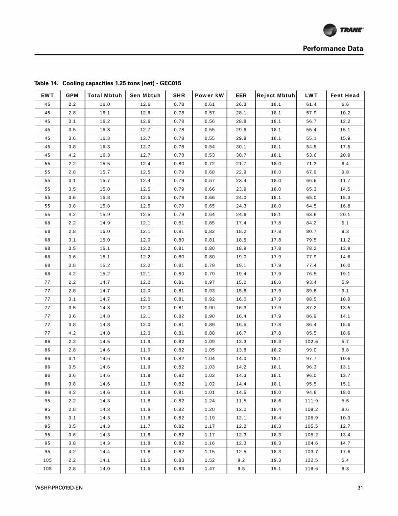
Table 14. Cooling capacities 1.25 tons (net) - GEC015
EWT GPM Total Mbtuh Sen Mbtuh SHR Power kW EER Reject Mbtuh LWT Feet Head45 2.2 16.0 12.6 0.78 0.61 26.3 18.1 61.4 6.6
45 2.8 16.1 12.6 0.78 0.57 28.1 18.1 57.9 10.2
45 3.1 16.2 12.6 0.78 0.56 28.8 18.1 56.7 12.2
45 3.5 16.3 12.7 0.78 0.55 29.6 18.1 55.4 15.1
45 3.6 16.3 12.7 0.78 0.55 29.8 18.1 55.1 15.9
45 3.8 16.3 12.7 0.78 0.54 30.1 18.1 54.5 17.5
45 4.2 16.3 12.7 0.78 0.53 30.7 18.1 53.6 20.9
55 2.2 15.5 12.4 0.80 0.72 21.7 18.0 71.3 6.4
55 2.8 15.7 12.5 0.79 0.68 22.9 18.0 67.9 9.8
55 3.1 15.7 12.4 0.79 0.67 23.4 18.0 66.6 11.7
55 3.5 15.8 12.5 0.79 0.66 23.9 18.0 65.3 14.5
55 3.6 15.8 12.5 0.79 0.66 24.0 18.1 65.0 15.3
55 3.8 15.8 12.5 0.79 0.65 24.3 18.0 64.5 16.8
55 4.2 15.9 12.5 0.79 0.64 24.6 18.1 63.6 20.1
68 2.2 14.9 12.1 0.81 0.85 17.4 17.8 84.2 6.1
68 2.8 15.0 12.1 0.81 0.82 18.2 17.8 80.7 9.3
68 3.1 15.0 12.0 0.80 0.81 18.5 17.8 79.5 11.2
68 3.5 15.1 12.2 0.81 0.80 18.9 17.8 78.2 13.9
68 3.6 15.1 12.2 0.80 0.80 19.0 17.9 77.9 14.6
68 3.8 15.2 12.2 0.81 0.79 19.1 17.9 77.4 16.0
68 4.2 15.2 12.1 0.80 0.79 19.4 17.9 76.5 19.1
77 2.2 14.7 12.0 0.81 0.97 15.2 18.0 93.4 5.9
77 2.8 14.7 12.0 0.81 0.93 15.8 17.9 89.8 9.1
77 3.1 14.7 12.0 0.81 0.92 16.0 17.9 88.5 10.9
77 3.5 14.8 12.0 0.81 0.90 16.3 17.9 87.2 13.5
77 3.6 14.8 12.1 0.82 0.90 16.4 17.9 86.9 14.1
77 3.8 14.8 12.0 0.81 0.89 16.5 17.8 86.4 15.6
77 4.2 14.8 12.0 0.81 0.88 16.7 17.8 85.5 18.6
86 2.2 14.5 11.9 0.82 1.09 13.3 18.3 102.6 5.7
86 2.8 14.6 11.9 0.82 1.05 13.8 18.2 99.0 8.8
86 3.1 14.6 11.9 0.82 1.04 14.0 18.1 97.7 10.6
86 3.5 14.6 11.9 0.82 1.03 14.2 18.1 96.3 13.1
86 3.6 14.6 11.9 0.82 1.02 14.3 18.1 96.0 13.7
86 3.8 14.6 11.9 0.82 1.02 14.4 18.1 95.5 15.1
86 4.2 14.6 11.9 0.81 1.01 14.5 18.0 94.6 18.0
95 2.2 14.3 11.8 0.82 1.24 11.5 18.6 111.9 5.6
95 2.8 14.3 11.8 0.82 1.20 12.0 18.4 108.2 8.6
95 3.1 14.3 11.8 0.82 1.19 12.1 18.4 106.9 10.3
95 3.5 14.3 11.7 0.82 1.17 12.2 18.3 105.5 12.7
95 3.6 14.3 11.8 0.82 1.17 12.3 18.3 105.2 13.4
95 3.8 14.3 11.8 0.82 1.16 12.3 18.3 104.6 14.7
95 4.2 14.4 11.8 0.82 1.15 12.5 18.3 103.7 17.6
105 2.2 14.1 11.6 0.83 1.52 9.2 19.3 122.5 5.4
105 2.8 14.0 11.6 0.83 1.47 9.5 19.1 118.6 8.3
WSHP-PRC019D-EN 31
Performance Data
105 3.1 14.0 11.6 0.83 1.45 9.7 19.0 117.2 10.0
105 3.5 14.0 11.6 0.83 1.43 9.8 18.9 115.8 12.4
105 3.6 14.0 11.6 0.83 1.44 9.7 18.9 115.5 13.0
105 3.8 14.0 11.6 0.83 1.42 9.9 18.9 114.9 14.3
105 4.2 14.0 11.6 0.83 1.41 10.0 18.8 114.0 17.1
115 2.2 13.7 11.5 0.84 1.76 7.8 19.7 133.0 4.5
115 2.8 13.7 11.5 0.84 1.73 7.9 19.6 129.0 8.1
115 3.1 13.7 11.5 0.84 1.72 8.0 19.6 127.6 9.9
115 3.5 13.7 11.5 0.84 1.70 8.1 19.5 126.2 12.3
115 3.6 13.7 11.5 0.84 1.70 8.1 19.5 125.8 12.9
115 3.8 13.7 11.5 0.84 1.69 8.1 19.5 125.2 14.1
115 4.2 13.7 11.5 0.84 1.67 8.2 19.4 124.2 16.5
120 2.2 13.6 11.4 0.84 1.90 7.2 20.0 138.2 4.4
120 2.8 13.6 11.4 0.84 1.87 7.3 19.9 134.2 8.0
120 3.1 13.6 11.4 0.84 1.85 7.3 19.9 132.8 9.8
120 3.5 13.5 11.4 0.84 1.83 7.4 19.8 131.3 12.2
120 3.6 13.5 11.4 0.84 1.83 7.4 19.8 131.0 12.8
120 3.8 13.5 11.4 0.84 1.82 7.4 19.8 130.4 14.0
120 4.2 13.5 11.4 0.84 1.80 7.5 19.7 129.4 16.4
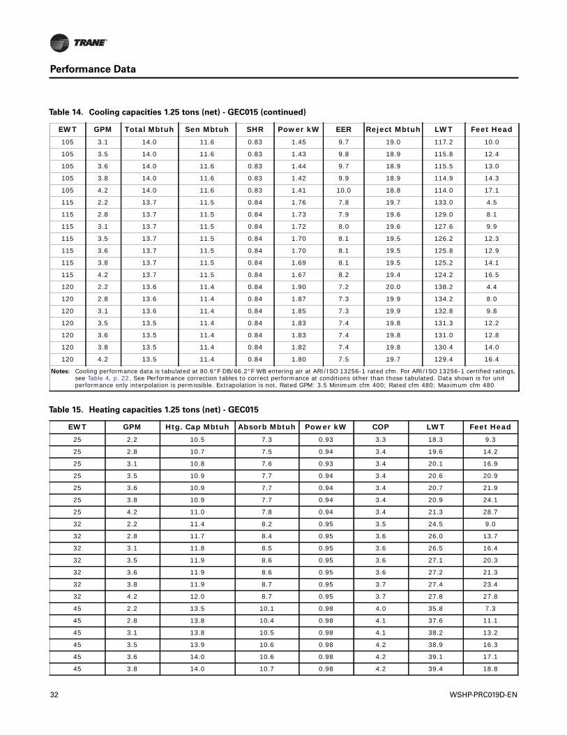
Notes: Cooling performance data is tabulated at 80.6°F DB/66.2°F WB entering air at ARI/ISO 13256-1 rated cfm. For ARI/ISO 13256-1 certified ratings, see Table 4, p. 22. See Performance correction tables to correct performance at conditions other than those tabulated. Data shown is for unit performance only interpolation is permissible. Extrapolation is not. Rated GPM: 3.5 Minimum cfm 400; Rated cfm 480; Maximum cfm 480
Table 14. Cooling capacities 1.25 tons (net) - GEC015 (continued)
EWT GPM Total Mbtuh Sen Mbtuh SHR Power kW EER Reject Mbtuh LWT Feet Head
Table 15. Heating capacities 1.25 tons (net) - GEC015
EWT GPM Htg. Cap Mbtuh Absorb Mbtuh Power kW COP LWT Feet Head25 2.2 10.5 7.3 0.93 3.3 18.3 9.3
25 2.8 10.7 7.5 0.94 3.4 19.6 14.2
25 3.1 10.8 7.6 0.93 3.4 20.1 16.9
25 3.5 10.9 7.7 0.94 3.4 20.6 20.9
25 3.6 10.9 7.7 0.94 3.4 20.7 21.9
25 3.8 10.9 7.7 0.94 3.4 20.9 24.1
25 4.2 11.0 7.8 0.94 3.4 21.3 28.7
32 2.2 11.4 8.2 0.95 3.5 24.5 9.0
32 2.8 11.7 8.4 0.95 3.6 26.0 13.7
32 3.1 11.8 8.5 0.95 3.6 26.5 16.4
32 3.5 11.9 8.6 0.95 3.6 27.1 20.3
32 3.6 11.9 8.6 0.95 3.6 27.2 21.3
32 3.8 11.9 8.7 0.95 3.7 27.4 23.4
32 4.2 12.0 8.7 0.95 3.7 27.8 27.8
45 2.2 13.5 10.1 0.98 4.0 35.8 7.3
45 2.8 13.8 10.4 0.98 4.1 37.6 11.1
45 3.1 13.8 10.5 0.98 4.1 38.2 13.2
45 3.5 13.9 10.6 0.98 4.2 38.9 16.3
45 3.6 14.0 10.6 0.98 4.2 39.1 17.1
45 3.8 14.0 10.7 0.98 4.2 39.4 18.8
32 WSHP-PRC019D-EN
Performance Data
45 4.2 14.1 10.7 0.98 4.2 39.9 22.4
55 2.2 15.0 11.6 0.99 4.4 44.5 7.0
55 2.8 15.3 11.9 1.00 4.5 46.5 10.6
55 3.1 15.5 12.0 1.00 4.5 47.2 12.7
55 3.5 15.5 12.1 1.00 4.6 48.1 15.7
55 3.6 15.6 12.2 1.00 4.6 48.2 16.5
55 3.8 15.6 12.2 1.00 4.6 48.6 18.1
55 4.2 15.7 12.3 1.00 4.6 49.1 21.5
68 2.2 17.0 13.6 1.00 5.0 55.7 6.7
68 2.8 17.4 13.9 1.00 5.1 58.0 10.1
68 3.1 17.5 14.1 1.00 5.1 58.9 12.1
68 3.5 17.7 14.3 1.01 5.2 59.8 14.9
68 3.6 17.7 14.3 1.00 5.2 60.1 15.7
68 3.8 17.7 14.3 1.00 5.2 60.5 17.2
68 4.2 17.9 14.4 1.00 5.2 61.1 20.5
75 2.2 18.1 14.6 1.00 5.3 61.7 6.5
75 2.8 18.5 15.1 1.01 5.4 64.2 9.9
75 3.1 18.6 15.2 1.00 5.4 65.2 11.8
75 3.5 18.8 15.4 1.00 5.5 66.2 14.6
75 3.6 18.8 15.4 1.00 5.5 66.4 15.3
75 3.8 18.9 15.5 1.00 5.5 66.9 16.8
75 4.2 19.0 15.6 1.00 5.6 67.6 20.0
86 2.2 19.7 16.3 1.00 5.8 71.2 6.3
86 2.8 20.2 16.8 0.99 6.0 74.0 9.6
86 3.1 20.3 17.0 0.99 6.0 75.1 11.4
86 3.5 20.5 17.2 0.99 6.1 76.2 14.1
86 3.6 20.5 17.1 0.99 6.1 76.5 14.8
86 3.8 20.6 17.2 0.98 6.1 76.9 16.2
86 4.2 20.8 17.4 0.98 6.2 77.7 19.3
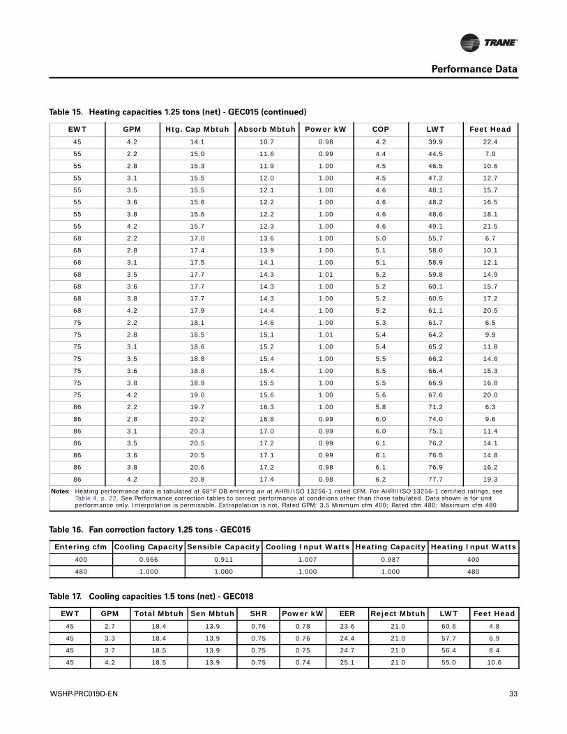
Notes: Heating performance data is tabulated at 68°F DB entering air at AHRI/ISO 13256-1 rated CFM. For AHRI/ISO 13256-1 certified ratings, see Table 4, p. 22. See Performance correction tables to correct performance at conditions other than those tabulated. Data shown is for unit performance only. Interpolation is permissible. Extrapolation is not. Rated GPM: 3.5 Minimum cfm 400; Rated cfm 480; Maximum cfm 480
Table 15. Heating capacities 1.25 tons (net) - GEC015 (continued)
EWT GPM Htg. Cap Mbtuh Absorb Mbtuh Power kW COP LWT Feet Head
Table 16. Fan correction factory 1.25 tons - GEC015
Entering cfm Cooling Capacity Sensible Capacity Cooling Input Watts Heating Capacity Heating Input Watts400 0.966 0.911 1.007 0.987 400
480 1.000 1.000 1.000 1.000 480
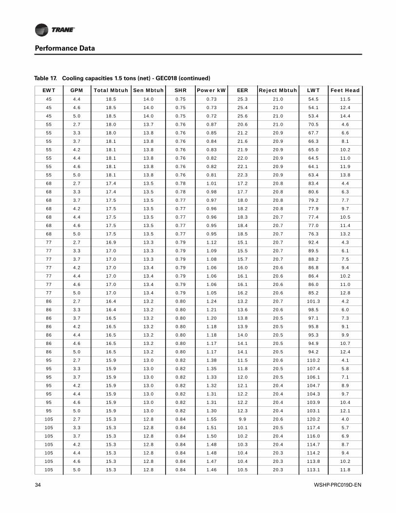
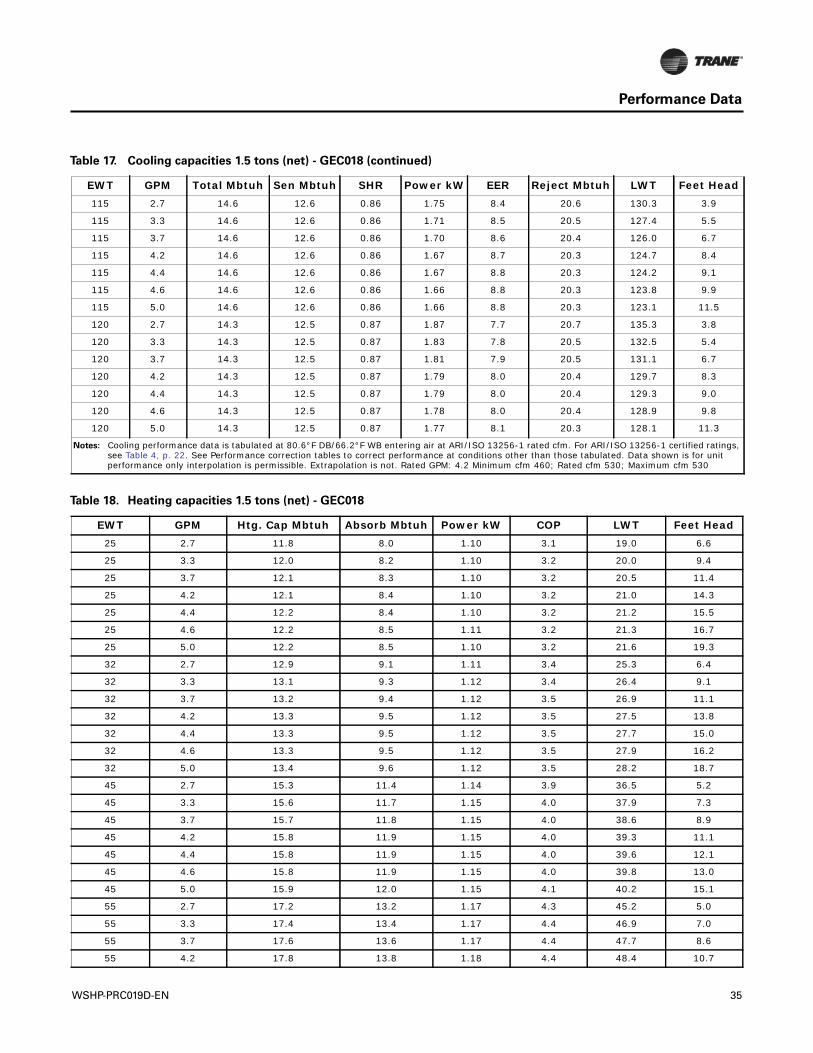
Table 17. Cooling capacities 1.5 tons (net) - GEC018
EWT GPM Total Mbtuh Sen Mbtuh SHR Power kW EER Reject Mbtuh LWT Feet Head45 2.7 18.4 13.9 0.76 0.78 23.6 21.0 60.6 4.8
45 3.3 18.4 13.9 0.75 0.76 24.4 21.0 57.7 6.9
45 3.7 18.5 13.9 0.75 0.75 24.7 21.0 56.4 8.4
45 4.2 18.5 13.9 0.75 0.74 25.1 21.0 55.0 10.6
WSHP-PRC019D-EN 33
Performance Data
45 4.4 18.5 14.0 0.75 0.73 25.3 21.0 54.5 11.5
45 4.6 18.5 14.0 0.75 0.73 25.4 21.0 54.1 12.4
45 5.0 18.5 14.0 0.75 0.72 25.6 21.0 53.4 14.4
55 2.7 18.0 13.7 0.76 0.87 20.6 21.0 70.5 4.6
55 3.3 18.0 13.8 0.76 0.85 21.2 20.9 67.7 6.6
55 3.7 18.1 13.8 0.76 0.84 21.6 20.9 66.3 8.1
55 4.2 18.1 13.8 0.76 0.83 21.9 20.9 65.0 10.2
55 4.4 18.1 13.8 0.76 0.82 22.0 20.9 64.5 11.0
55 4.6 18.1 13.8 0.76 0.82 22.1 20.9 64.1 11.9
55 5.0 18.1 13.8 0.76 0.81 22.3 20.9 63.4 13.8
68 2.7 17.4 13.5 0.78 1.01 17.2 20.8 83.4 4.4
68 3.3 17.4 13.5 0.78 0.98 17.7 20.8 80.6 6.3
68 3.7 17.5 13.5 0.77 0.97 18.0 20.8 79.2 7.7
68 4.2 17.5 13.5 0.77 0.96 18.2 20.8 77.9 9.7
68 4.4 17.5 13.5 0.77 0.96 18.3 20.7 77.4 10.5
68 4.6 17.5 13.5 0.77 0.95 18.4 20.7 77.0 11.4
68 5.0 17.5 13.5 0.77 0.95 18.5 20.7 76.3 13.2
77 2.7 16.9 13.3 0.79 1.12 15.1 20.7 92.4 4.3
77 3.3 17.0 13.3 0.79 1.09 15.5 20.7 89.5 6.1
77 3.7 17.0 13.3 0.79 1.08 15.7 20.7 88.2 7.5
77 4.2 17.0 13.4 0.79 1.06 16.0 20.6 86.8 9.4
77 4.4 17.0 13.4 0.79 1.06 16.1 20.6 86.4 10.2
77 4.6 17.0 13.4 0.79 1.06 16.1 20.6 86.0 11.0
77 5.0 17.0 13.4 0.79 1.05 16.2 20.6 85.2 12.8
86 2.7 16.4 13.2 0.80 1.24 13.2 20.7 101.3 4.2
86 3.3 16.4 13.2 0.80 1.21 13.6 20.6 98.5 6.0
86 3.7 16.5 13.2 0.80 1.20 13.8 20.5 97.1 7.3
86 4.2 16.5 13.2 0.80 1.18 13.9 20.5 95.8 9.1
86 4.4 16.5 13.2 0.80 1.18 14.0 20.5 95.3 9.9
86 4.6 16.5 13.2 0.80 1.17 14.1 20.5 94.9 10.7
86 5.0 16.5 13.2 0.80 1.17 14.1 20.5 94.2 12.4
95 2.7 15.9 13.0 0.82 1.38 11.5 20.6 110.2 4.1
95 3.3 15.9 13.0 0.82 1.35 11.8 20.5 107.4 5.8
95 3.7 15.9 13.0 0.82 1.33 12.0 20.5 106.1 7.1
95 4.2 15.9 13.0 0.82 1.32 12.1 20.4 104.7 8.9
95 4.4 15.9 13.0 0.82 1.31 12.2 20.4 104.3 9.7
95 4.6 15.9 13.0 0.82 1.31 12.2 20.4 103.9 10.4
95 5.0 15.9 13.0 0.82 1.30 12.3 20.4 103.1 12.1
105 2.7 15.3 12.8 0.84 1.55 9.9 20.6 120.2 4.0
105 3.3 15.3 12.8 0.84 1.51 10.1 20.5 117.4 5.7
105 3.7 15.3 12.8 0.84 1.50 10.2 20.4 116.0 6.9
105 4.2 15.3 12.8 0.84 1.48 10.3 20.4 114.7 8.7
105 4.4 15.3 12.8 0.84 1.48 10.4 20.3 114.2 9.4
105 4.6 15.3 12.8 0.84 1.47 10.4 20.3 113.8 10.2
105 5.0 15.3 12.8 0.84 1.46 10.5 20.3 113.1 11.8
Table 17. Cooling capacities 1.5 tons (net) - GEC018 (continued)
EWT GPM Total Mbtuh Sen Mbtuh SHR Power kW EER Reject Mbtuh LWT Feet Head
34 WSHP-PRC019D-EN
Performance Data
115 2.7 14.6 12.6 0.86 1.75 8.4 20.6 130.3 3.9
115 3.3 14.6 12.6 0.86 1.71 8.5 20.5 127.4 5.5
115 3.7 14.6 12.6 0.86 1.70 8.6 20.4 126.0 6.7
115 4.2 14.6 12.6 0.86 1.67 8.7 20.3 124.7 8.4
115 4.4 14.6 12.6 0.86 1.67 8.8 20.3 124.2 9.1
115 4.6 14.6 12.6 0.86 1.66 8.8 20.3 123.8 9.9
115 5.0 14.6 12.6 0.86 1.66 8.8 20.3 123.1 11.5
120 2.7 14.3 12.5 0.87 1.87 7.7 20.7 135.3 3.8
120 3.3 14.3 12.5 0.87 1.83 7.8 20.5 132.5 5.4
120 3.7 14.3 12.5 0.87 1.81 7.9 20.5 131.1 6.7
120 4.2 14.3 12.5 0.87 1.79 8.0 20.4 129.7 8.3
120 4.4 14.3 12.5 0.87 1.79 8.0 20.4 129.3 9.0
120 4.6 14.3 12.5 0.87 1.78 8.0 20.4 128.9 9.8
120 5.0 14.3 12.5 0.87 1.77 8.1 20.3 128.1 11.3
Notes: Cooling performance data is tabulated at 80.6°F DB/66.2°F WB entering air at ARI/ISO 13256-1 rated cfm. For ARI/ISO 13256-1 certified ratings, see Table 4, p. 22. See Performance correction tables to correct performance at conditions other than those tabulated. Data shown is for unit performance only interpolation is permissible. Extrapolation is not. Rated GPM: 4.2 Minimum cfm 460; Rated cfm 530; Maximum cfm 530
Table 17. Cooling capacities 1.5 tons (net) - GEC018 (continued)
EWT GPM Total Mbtuh Sen Mbtuh SHR Power kW EER Reject Mbtuh LWT Feet Head
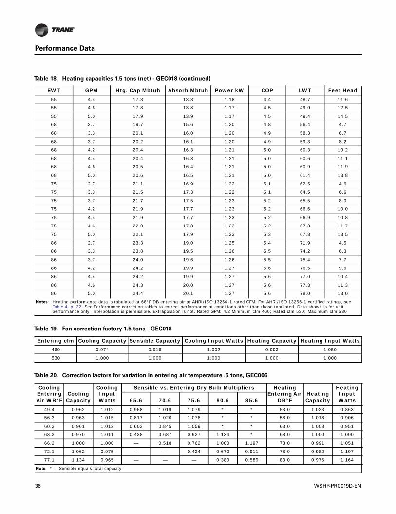
Table 18. Heating capacities 1.5 tons (net) - GEC018
EWT GPM Htg. Cap Mbtuh Absorb Mbtuh Power kW COP LWT Feet Head25 2.7 11.8 8.0 1.10 3.1 19.0 6.6
25 3.3 12.0 8.2 1.10 3.2 20.0 9.4
25 3.7 12.1 8.3 1.10 3.2 20.5 11.4
25 4.2 12.1 8.4 1.10 3.2 21.0 14.3
25 4.4 12.2 8.4 1.10 3.2 21.2 15.5
25 4.6 12.2 8.5 1.11 3.2 21.3 16.7
25 5.0 12.2 8.5 1.10 3.2 21.6 19.3
32 2.7 12.9 9.1 1.11 3.4 25.3 6.4
32 3.3 13.1 9.3 1.12 3.4 26.4 9.1
32 3.7 13.2 9.4 1.12 3.5 26.9 11.1
32 4.2 13.3 9.5 1.12 3.5 27.5 13.8
32 4.4 13.3 9.5 1.12 3.5 27.7 15.0
32 4.6 13.3 9.5 1.12 3.5 27.9 16.2
32 5.0 13.4 9.6 1.12 3.5 28.2 18.7
45 2.7 15.3 11.4 1.14 3.9 36.5 5.2
45 3.3 15.6 11.7 1.15 4.0 37.9 7.3
45 3.7 15.7 11.8 1.15 4.0 38.6 8.9
45 4.2 15.8 11.9 1.15 4.0 39.3 11.1
45 4.4 15.8 11.9 1.15 4.0 39.6 12.1
45 4.6 15.8 11.9 1.15 4.0 39.8 13.0
45 5.0 15.9 12.0 1.15 4.1 40.2 15.1
55 2.7 17.2 13.2 1.17 4.3 45.2 5.0
55 3.3 17.4 13.4 1.17 4.4 46.9 7.0
55 3.7 17.6 13.6 1.17 4.4 47.7 8.6
55 4.2 17.8 13.8 1.18 4.4 48.4 10.7
WSHP-PRC019D-EN 35
Performance Data
55 4.4 17.8 13.8 1.18 4.4 48.7 11.6
55 4.6 17.8 13.8 1.17 4.5 49.0 12.5
55 5.0 17.9 13.9 1.17 4.5 49.4 14.5
68 2.7 19.7 15.6 1.20 4.8 56.4 4.7
68 3.3 20.1 16.0 1.20 4.9 58.3 6.7
68 3.7 20.2 16.1 1.20 4.9 59.3 8.2
68 4.2 20.4 16.3 1.21 5.0 60.3 10.2
68 4.4 20.4 16.3 1.21 5.0 60.6 11.1
68 4.6 20.5 16.4 1.21 5.0 60.9 11.9
68 5.0 20.6 16.5 1.21 5.0 61.4 13.8
75 2.7 21.1 16.9 1.22 5.1 62.5 4.6
75 3.3 21.5 17.3 1.22 5.1 64.5 6.6
75 3.7 21.7 17.5 1.23 5.2 65.5 8.0
75 4.2 21.9 17.7 1.23 5.2 66.6 10.0
75 4.4 21.9 17.7 1.23 5.2 66.9 10.8
75 4.6 22.0 17.8 1.23 5.2 67.3 11.7
75 5.0 22.1 17.9 1.23 5.3 67.8 13.5
86 2.7 23.3 19.0 1.25 5.4 71.9 4.5
86 3.3 23.8 19.5 1.26 5.5 74.2 6.3
86 3.7 24.0 19.6 1.26 5.5 75.4 7.7
86 4.2 24.2 19.9 1.27 5.6 76.5 9.6
86 4.4 24.2 19.9 1.27 5.6 77.0 10.4
86 4.6 24.3 20.0 1.27 5.6 77.3 11.3
86 5.0 24.4 20.1 1.27 5.6 78.0 13.0
Notes: Heating performance data is tabulated at 68°F DB entering air at AHRI/ISO 13256-1 rated CFM. For AHRI/ISO 13256-1 certified ratings, see Table 4, p. 22. See Performance correction tables to correct performance at conditions other than those tabulated. Data shown is for unit performance only. Interpolation is permissible. Extrapolation is not. Rated GPM: 4.2 Minimum cfm 460; Rated cfm 530; Maximum cfm 530
Table 18. Heating capacities 1.5 tons (net) - GEC018 (continued)
EWT GPM Htg. Cap Mbtuh Absorb Mbtuh Power kW COP LWT Feet Head
Table 19. Fan correction factory 1.5 tons - GEC018
Entering cfm Cooling Capacity Sensible Capacity Cooling Input Watts Heating Capacity Heating Input Watts460 0.974 0.916 1.002 0.993 1.050
530 1.000 1.000 1.000 1.000 1.000
Table 20. Correction factors for variation in entering air temperature .5 tons, GEC006
Cooling Entering Air WB°F
Cooling Capacity
Cooling Input Watts
Sensible vs. Entering Dry Bulb Multipliers Heating Entering Air
DB°FHeating Capacity
Heating Input Watts65.6 70.6 75.6 80.6 85.6
49.4 0.962 1.012 0.958 1.019 1.079 * * 53.0 1.023 0.863
56.3 0.963 1.015 0.817 1.020 1.078 * * 58.0 1.018 0.906
60.3 0.961 1.012 0.603 0.845 1.059 * * 63.0 1.008 0.951
63.2 0.970 1.011 0.438 0.687 0.927 1.134 * 68.0 1.000 1.000
66.2 1.000 1.000 — 0.518 0.762 1.000 1.197 73.0 0.991 1.051
72.1 1.062 0.975 — — 0.424 0.670 0.911 78.0 0.982 1.107
77.1 1.134 0.965 — — — 0.380 0.589 83.0 0.975 1.164
Note: * = Sensible equals total capacity
36 WSHP-PRC019D-EN
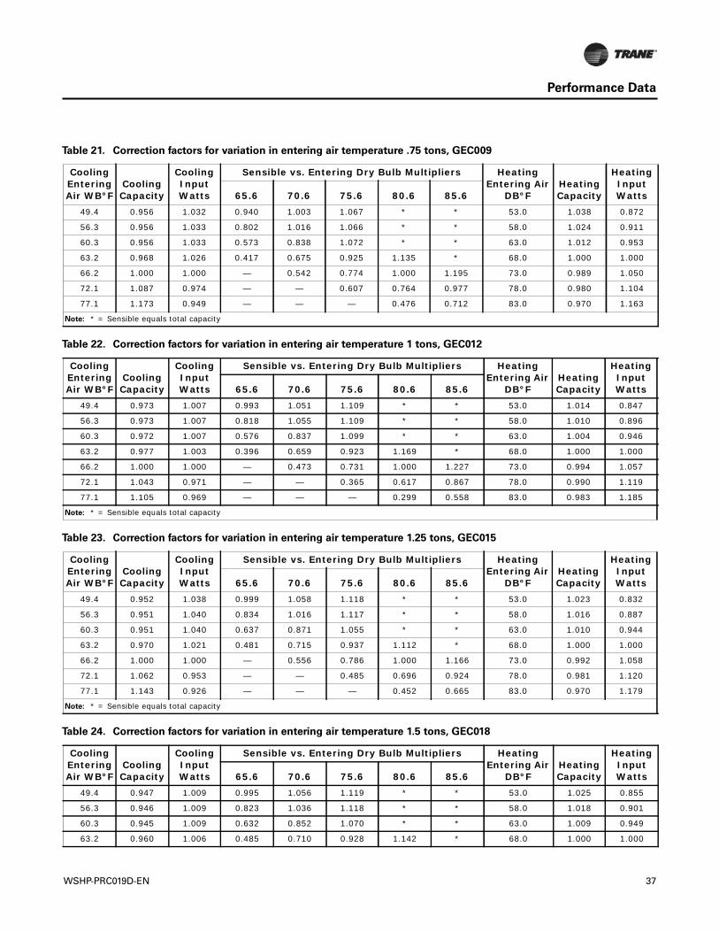
Performance Data
Table 21. Correction factors for variation in entering air temperature .75 tons, GEC009
Cooling Entering Air WB°F
Cooling Capacity
Cooling Input Watts
Sensible vs. Entering Dry Bulb Multipliers Heating Entering Air
DB°FHeating Capacity
Heating Input Watts65.6 70.6 75.6 80.6 85.6
49.4 0.956 1.032 0.940 1.003 1.067 * * 53.0 1.038 0.872
56.3 0.956 1.033 0.802 1.016 1.066 * * 58.0 1.024 0.911
60.3 0.956 1.033 0.573 0.838 1.072 * * 63.0 1.012 0.953
63.2 0.968 1.026 0.417 0.675 0.925 1.135 * 68.0 1.000 1.000
66.2 1.000 1.000 — 0.542 0.774 1.000 1.195 73.0 0.989 1.050
72.1 1.087 0.974 — — 0.607 0.764 0.977 78.0 0.980 1.104
77.1 1.173 0.949 — — — 0.476 0.712 83.0 0.970 1.163
Note: * = Sensible equals total capacity
Table 22. Correction factors for variation in entering air temperature 1 tons, GEC012
Cooling Entering Air WB°F
Cooling Capacity
Cooling Input Watts
Sensible vs. Entering Dry Bulb Multipliers Heating Entering Air
DB°FHeating Capacity
Heating Input Watts65.6 70.6 75.6 80.6 85.6
49.4 0.973 1.007 0.993 1.051 1.109 * * 53.0 1.014 0.847
56.3 0.973 1.007 0.818 1.055 1.109 * * 58.0 1.010 0.896
60.3 0.972 1.007 0.576 0.837 1.099 * * 63.0 1.004 0.946
63.2 0.977 1.003 0.396 0.659 0.923 1.169 * 68.0 1.000 1.000
66.2 1.000 1.000 — 0.473 0.731 1.000 1.227 73.0 0.994 1.057
72.1 1.043 0.971 — — 0.365 0.617 0.867 78.0 0.990 1.119
77.1 1.105 0.969 — — — 0.299 0.558 83.0 0.983 1.185
Note: * = Sensible equals total capacity
Table 23. Correction factors for variation in entering air temperature 1.25 tons, GEC015
Cooling Entering Air WB°F
Cooling Capacity
Cooling Input Watts
Sensible vs. Entering Dry Bulb Multipliers Heating Entering Air
DB°FHeating Capacity
Heating Input Watts65.6 70.6 75.6 80.6 85.6
49.4 0.952 1.038 0.999 1.058 1.118 * * 53.0 1.023 0.832
56.3 0.951 1.040 0.834 1.016 1.117 * * 58.0 1.016 0.887
60.3 0.951 1.040 0.637 0.871 1.055 * * 63.0 1.010 0.944
63.2 0.970 1.021 0.481 0.715 0.937 1.112 * 68.0 1.000 1.000
66.2 1.000 1.000 — 0.556 0.786 1.000 1.166 73.0 0.992 1.058
72.1 1.062 0.953 — — 0.485 0.696 0.924 78.0 0.981 1.120
77.1 1.143 0.926 — — — 0.452 0.665 83.0 0.970 1.179
Note: * = Sensible equals total capacity
Table 24. Correction factors for variation in entering air temperature 1.5 tons, GEC018
Cooling Entering Air WB°F
Cooling Capacity
Cooling Input Watts
Sensible vs. Entering Dry Bulb Multipliers Heating Entering Air
DB°FHeating Capacity
Heating Input Watts65.6 70.6 75.6 80.6 85.6
49.4 0.947 1.009 0.995 1.056 1.119 * * 53.0 1.025 0.855
56.3 0.946 1.009 0.823 1.036 1.118 * * 58.0 1.018 0.901
60.3 0.945 1.009 0.632 0.852 1.070 * * 63.0 1.009 0.949
63.2 0.960 1.006 0.485 0.710 0.928 1.142 * 68.0 1.000 1.000
WSHP-PRC019D-EN 37
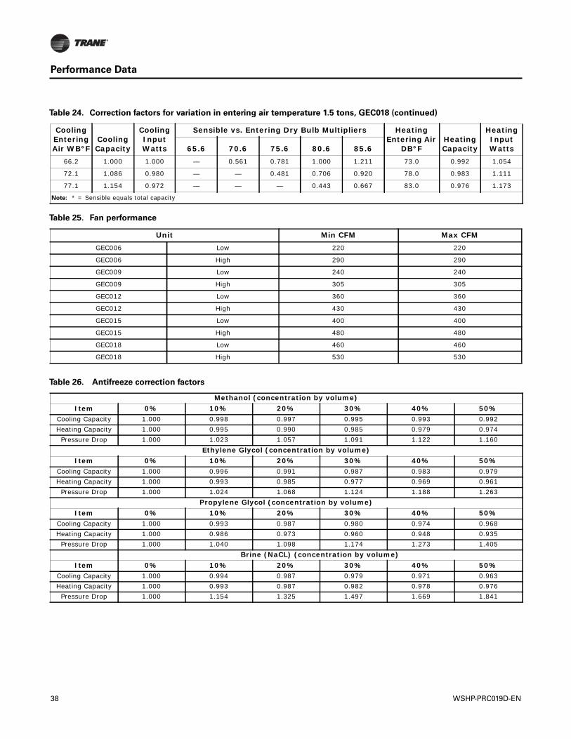
Performance Data
66.2 1.000 1.000 — 0.561 0.781 1.000 1.211 73.0 0.992 1.054
72.1 1.086 0.980 — — 0.481 0.706 0.920 78.0 0.983 1.111
77.1 1.154 0.972 — — — 0.443 0.667 83.0 0.976 1.173
Note: * = Sensible equals total capacity
Table 24. Correction factors for variation in entering air temperature 1.5 tons, GEC018 (continued)
Cooling Entering Air WB°F
Cooling Capacity
Cooling Input Watts
Sensible vs. Entering Dry Bulb Multipliers Heating Entering Air
DB°FHeating Capacity
Heating Input Watts65.6 70.6 75.6 80.6 85.6
Table 25. Fan performance
Unit Min CFM Max CFMGEC006 Low 220 220
GEC006 High 290 290
GEC009 Low 240 240
GEC009 High 305 305
GEC012 Low 360 360
GEC012 High 430 430
GEC015 Low 400 400
GEC015 High 480 480
GEC018 Low 460 460
GEC018 High 530 530
Table 26. Antifreeze correction factors
Methanol (concentration by volume)Item 0% 10% 20% 30% 40% 50%
Cooling Capacity 1.000 0.998 0.997 0.995 0.993 0.992 Heating Capacity 1.000 0.995 0.990 0.985 0.979 0.974
Pressure Drop 1.000 1.023 1.057 1.091 1.122 1.160 Ethylene Glycol (concentration by volume)
Item 0% 10% 20% 30% 40% 50%Cooling Capacity 1.000 0.996 0.991 0.987 0.983 0.979 Heating Capacity 1.000 0.993 0.985 0.977 0.969 0.961
Pressure Drop 1.000 1.024 1.068 1.124 1.188 1.263 Propylene Glycol (concentration by volume)
Item 0% 10% 20% 30% 40% 50%Cooling Capacity 1.000 0.993 0.987 0.980 0.974 0.968 Heating Capacity 1.000 0.986 0.973 0.960 0.948 0.935
Pressure Drop 1.000 1.040 1.098 1.174 1.273 1.405 Brine (NaCL) (concentration by volume)
Item 0% 10% 20% 30% 40% 50%Cooling Capacity 1.000 0.994 0.987 0.979 0.971 0.963 Heating Capacity 1.000 0.993 0.987 0.982 0.978 0.976
Pressure Drop 1.000 1.154 1.325 1.497 1.669 1.841
38 WSHP-PRC019D-EN
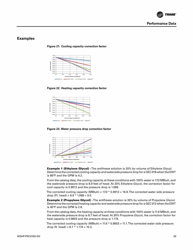
Performance Data
Examples
Example 1 (Ethylene Glycol) -The antifreeze solution is 20% by volume of Ethylene Glycol.Determine the corrected cooling capacity and waterside pressure drop for a GEC 018 when the EWTis 86°F and the GPM is 4.2.
From the catalog data, the cooling capacity at these conditions with 100% water is 17.0 MBtuh, andthe waterside pressure drop is 8.9 feet of head. At 20% Ethylene Glycol, the correction factor forcool capacity is 0.9912 and the pressure drop is 1.068.
The corrected cooling capacity (MBtuh) = 17.0 * 0.9912 = 16.9.The corrected water side pressuredrop (Ft. head) = 8.9 * 1.068 = 9.5.
Example 2 (Propylene Glycol) -The antifreeze solution is 30% by volume of Propylene Glycol.Determine the corrected heating capacity and waterside pressure drop for a GEC 012 when the EWTis 45°F and the GPM is 2.8.
From the catalog data, the heating capacity at these conditions with 100% water is 11.6 MBtuh, andthe waterside pressure drop is 8.7 feet of head. At 30% Propylene Glycol, the correction factor forheat capacity is 0.9603 and the pressure drop is 1.174.
The corrected cooling capacity (MBtuh) = 11.6 * 0.9603 = 11.1.The corrected water side pressuredrop (ft. head) = 8.7 * 1.174 = 10.2.
Figure 21. Cooling capacity correction factor
Figure 22. Heating capacity correction factor
Figure 23. Water pressure drop correction factor
0.960
0.965
0.970
0.975
0.980
0.985
0.990
0.995
1.000
1.005
0% 10% 20% 30% 40% 50%
Cor
rect
ion
Fact
or
Percent Volume of Antifreeze
Methanol Ethylene Glycol Propylene Glycol NaCl
0.930
0.940
0.950
0.960
0.970
0.980
0.990
1.000
1.010
0% 10% 20% 30% 40% 50%
Cor
rect
ion
Fact
or
Percent Volume of Antifreeze
Methanol Ethylene Glycol Propylene Glycol NaCl
1.00
1.10
1.20
1.30
1.40
1.50
1.60
1.70
1.80
1.90
0% 10% 20% 30% 40% 50%
Cor
rect
ion
Fact
or
Percent Volume of Antifreeze
Methanol Ethylene Glycol Propylene Glycol NaCl
WSHP-PRC019D-EN 39
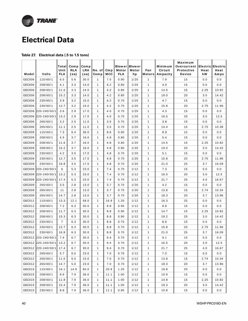
Electrical Data
Table 27. Electrical data (.5 to 1.5 tons)
Model Volts
Total Unit FLA
CompRLA(ea)
CompLRA(ea)
No. ofComp
CmpMCC
BlowerMotorFLA
BlowerMotor
hpFan
Motors
Minimum Circuit
Ampacity
Maximum Overcurrent Protective
Device
Electric Heat kW
Electric Heat Amps
GEC006 115/60/1 6.5 5.6 30.0 1 7.5 0.90 1/20 1 7.9 15 0.0 0.0
GEC006 208/60/1 4.1 3.3 14.0 1 4.2 0.80 1/20 1 4.9 15 0.0 0.0
GEC006 208/60/1 11.6 3.3 14.0 1 4.2 0.80 1/20 1 14.5 15 2.25 10.82
GEC006 208/60/1 15.2 3.3 14.0 1 4.2 0.80 1/20 1 19.0 20 3.0 14.42
GEC006 230/60/1 3.9 3.2 15.0 1 4.2 0.70 1/20 1 4.7 15 0.0 0.0
GEC006 230/60/1 12.7 3.2 15.0 1 4.2 0.70 1/20 1 15.8 20 2.75 11.96
GEC006 220-240/50/1 3.6 2.9 17.0 1 4.0 0.70 1/20 1 4.3 15 0.0 0.0
GEC006 220-240/50/1 13.2 2.9 17.0 1 4.0 0.70 1/20 1 16.5 20 3.0 12.5
GEC006 265/60/1 3.2 2.5 11.0 1 3.5 0.70 1/20 1 3.8 15 0.0 0.0
GEC006 265/60/1 11.1 2.5 11.0 1 3.5 0.70 1/20 1 14.4 15 2.75 10.38
GEC009 115/60/1 7.3 6.4 36.0 1 8.6 0.90 1/20 1 8.9 15 0.0 0.0
GEC009 208/60/1 4.5 3.7 16.0 1 4.8 0.80 1/20 1 5.4 15 0.0 0.0
GEC009 208/60/1 11.6 3.7 16.0 1 4.8 0.80 1/20 1 14.5 15 2.25 10.82
GEC009 208/60/1 15.2 3.7 16.0 1 4.8 0.80 1/20 1 19.0 20 3.0 14.42
GEC009 230/60/1 4.2 3.5 17.0 1 4.8 0.70 1/20 1 5.1 15 0.0 0.0
GEC009 230/60/1 12.7 3.5 17.0 1 4.8 0.70 1/20 1 15.8 20 2.75 11.96
GEC009 230/60/1 16.8 3.5 17.0 1 4.8 0.70 1/20 1 21.0 25 3.7 16.09
GEC009 220-240/50/1 6 5.3 23.0 1 7.4 0.70 1/12 1 7.3 15 0.0 0.0
GEC009 220-240/50/1 13.2 5.3 23.0 1 7.4 0.70 1/12 1 16.5 20 3.0 12.5
GEC009 220-240/50/1 17.4 5.3 23.0 1 7.4 0.70 1/12 1 21.7 25 4.0 16.67
GEC009 265/60/1 3.5 2.8 13.0 1 3.7 0.70 1/20 1 4.2 15 0.0 0.0
GEC009 265/60/1 11 2.8 13.0 1 3.7 0.70 1/20 1 13.8 15 2.74 10.34
GEC009 265/60/1 14.7 2.8 13.0 1 3.7 0.70 1/20 1 18.3 20 3.7 13.96
GEC012 115/60/1 13.3 12.1 58.0 1 16.9 1.20 1/12 1 16.3 25 0.0 0.0
GEC012 208/60/1 7.2 6.3 30.0 1 8.8 0.90 1/12 1 8.8 15 0.0 0.0
GEC012 208/60/1 11.7 6.3 30.0 1 8.8 0.90 1/12 1 14.7 15 2.25 10.82
GEC012 208/60/1 15.3 6.3 30.0 1 8.8 0.90 1/12 1 19.2 20 3.0 14.42
GEC012 230/60/1 7 6.3 30.0 1 8.8 0.70 1/12 1 8.6 15 0.0 0.0
GEC012 230/60/1 12.7 6.3 30.0 1 8.8 0.70 1/12 1 15.8 20 2.75 11.96
GEC012 230/60/1 16.8 6.3 30.0 1 8.8 0.70 1/12 1 21.0 25 3.7 16.09
GEC012 220-240/50/1 7.4 6.7 30.0 1 9.4 0.70 1/12 1 9.1 15 0.0 0.0
GEC012 220-240/50/1 13.2 6.7 30.0 1 9.4 0.70 1/12 1 16.5 20 3.0 12.5
GEC012 220-240/50/1 17.4 6.7 30.0 1 9.4 0.70 1/12 1 21.7 25 4.0 16.67
GEC012 265/60/1 5.7 5.0 23.0 1 7.0 0.70 1/12 1 7.0 15 0.0 0.0
GEC012 265/60/1 11.0 5.0 23.0 1 7.0 0.70 1/12 1 13.8 15 2.74 10.34
GEC012 265/60/1 14.7 5.0 23.0 1 7.0 0.70 1/12 1 18.3 20 3.7 13.96
GEC015 115/60/1 16.1 14.9 60.0 1 20.9 1.20 1/12 1 19.8 20 0.0 0.0
GEC015 208/60/1 8.9 7.9 36.0 1 11.1 1.00 1/12 1 10.9 15 0.0 0.0
GEC015 208/60/1 11.8 7.9 36.0 1 11.1 1.00 1/12 1 14.8 15 2.25 10.82
GEC015 208/60/1 15.4 7.9 36.0 1 11.1 1.00 1/12 1 19.3 20 3.0 14.42
GEC015 230/60/1 8.8 7.9 36.0 1 11.1 0.90 1/12 1 10.8 15 0.0 0.0
40 WSHP-PRC019D-EN
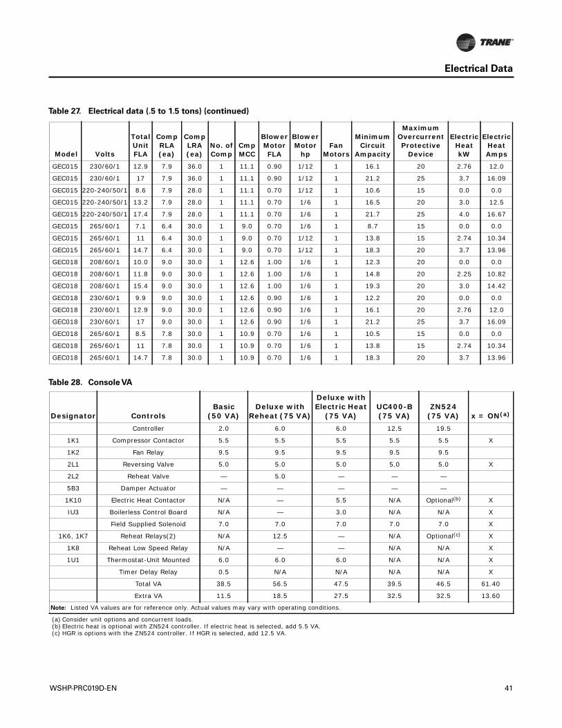
Electrical Data
GEC015 230/60/1 12.9 7.9 36.0 1 11.1 0.90 1/12 1 16.1 20 2.76 12.0
GEC015 230/60/1 17 7.9 36.0 1 11.1 0.90 1/12 1 21.2 25 3.7 16.09
GEC015 220-240/50/1 8.6 7.9 28.0 1 11.1 0.70 1/12 1 10.6 15 0.0 0.0
GEC015 220-240/50/1 13.2 7.9 28.0 1 11.1 0.70 1/6 1 16.5 20 3.0 12.5
GEC015 220-240/50/1 17.4 7.9 28.0 1 11.1 0.70 1/6 1 21.7 25 4.0 16.67
GEC015 265/60/1 7.1 6.4 30.0 1 9.0 0.70 1/6 1 8.7 15 0.0 0.0
GEC015 265/60/1 11 6.4 30.0 1 9.0 0.70 1/12 1 13.8 15 2.74 10.34
GEC015 265/60/1 14.7 6.4 30.0 1 9.0 0.70 1/12 1 18.3 20 3.7 13.96
GEC018 208/60/1 10.0 9.0 30.0 1 12.6 1.00 1/6 1 12.3 20 0.0 0.0
GEC018 208/60/1 11.8 9.0 30.0 1 12.6 1.00 1/6 1 14.8 20 2.25 10.82
GEC018 208/60/1 15.4 9.0 30.0 1 12.6 1.00 1/6 1 19.3 20 3.0 14.42
GEC018 230/60/1 9.9 9.0 30.0 1 12.6 0.90 1/6 1 12.2 20 0.0 0.0
GEC018 230/60/1 12.9 9.0 30.0 1 12.6 0.90 1/6 1 16.1 20 2.76 12.0
GEC018 230/60/1 17 9.0 30.0 1 12.6 0.90 1/6 1 21.2 25 3.7 16.09
GEC018 265/60/1 8.5 7.8 30.0 1 10.9 0.70 1/6 1 10.5 15 0.0 0.0
GEC018 265/60/1 11 7.8 30.0 1 10.9 0.70 1/6 1 13.8 15 2.74 10.34
GEC018 265/60/1 14.7 7.8 30.0 1 10.9 0.70 1/6 1 18.3 20 3.7 13.96
Table 27. Electrical data (.5 to 1.5 tons) (continued)
Model Volts
Total Unit FLA
CompRLA(ea)
CompLRA(ea)
No. ofComp
CmpMCC
BlowerMotorFLA
BlowerMotor
hpFan
Motors
Minimum Circuit
Ampacity
Maximum Overcurrent Protective
Device
Electric Heat kW
Electric Heat Amps
Table 28. Console VA
Designator Controls
Basic (50 VA)
Deluxe with Reheat (75 VA)
Deluxe with Electric Heat
(75 VA)UC400-B(75 VA)
ZN524 (75 VA) x = ON(a)
Controller 2.0 6.0 6.0 12.5 19.5
1K1 Compressor Contactor 5.5 5.5 5.5 5.5 5.5 X
1K2 Fan Relay 9.5 9.5 9.5 9.5 9.5
2L1 Reversing Valve 5.0 5.0 5.0 5.0 5.0 X
2L2 Reheat Valve — 5.0 — — —
5B3 Damper Actuator — — — — —
1K10 Electric Heat Contactor N/A — 5.5 N/A Optional(b) X
IU3 Boilerless Control Board N/A — 3.0 N/A N/A X
Field Supplied Solenoid 7.0 7.0 7.0 7.0 7.0 X
1K6, 1K7 Reheat Relays(2) N/A 12.5 — N/A Optional(c) X
1K8 Reheat Low Speed Relay N/A — — N/A N/A X
1U1 Thermostat-Unit Mounted 6.0 6.0 6.0 N/A N/A X
Timer Delay Relay 0.5 N/A N/A N/A N/A X
Total VA 38.5 56.5 47.5 39.5 46.5 61.40
Extra VA 11.5 18.5 27.5 32.5 32.5 13.60
Note: Listed VA values are for reference only. Actual values may vary with operating conditions.
(a) Consider unit options and concurrent loads.(b) Electric heat is optional with ZN524 controller. If electric heat is selected, add 5.5 VA.(c) HGR is options with the ZN524 controller. If HGR is selected, add 12.5 VA.
WSHP-PRC019D-EN 41
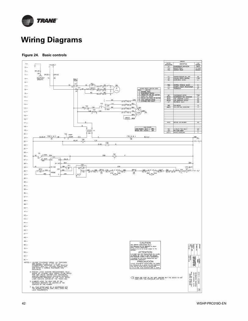
Wiring Diagrams
Figure 24. Basic controls
42 WSHP-PRC019D-EN
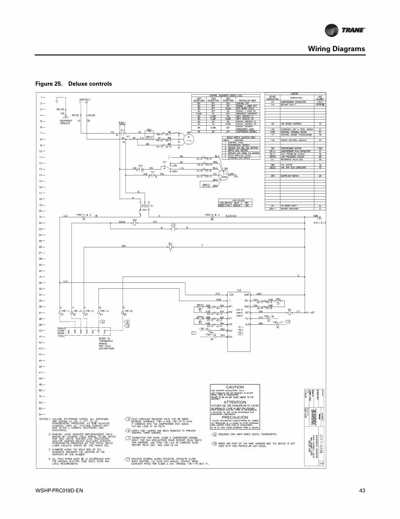
Wiring Diagrams
Figure 25. Deluxe controls
WSHP-PRC019D-EN 43
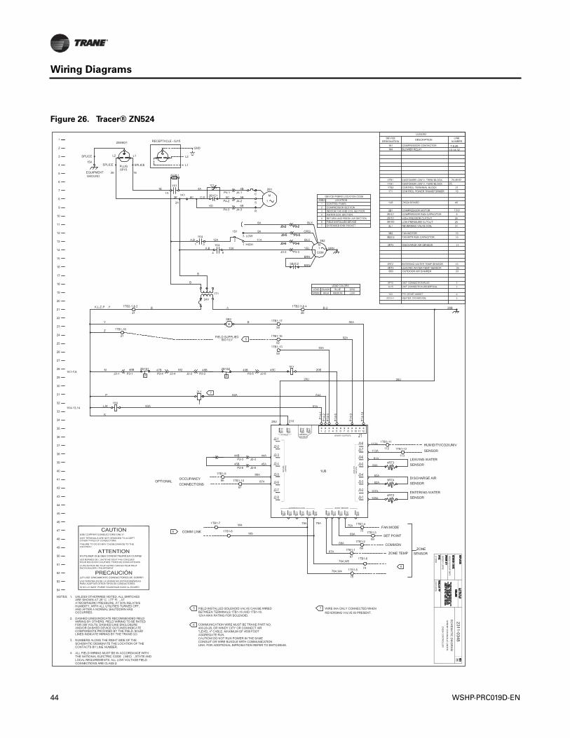
Wiring Diagrams
Figure 26. Tracer® ZN524
44 WSHP-PRC019D-EN
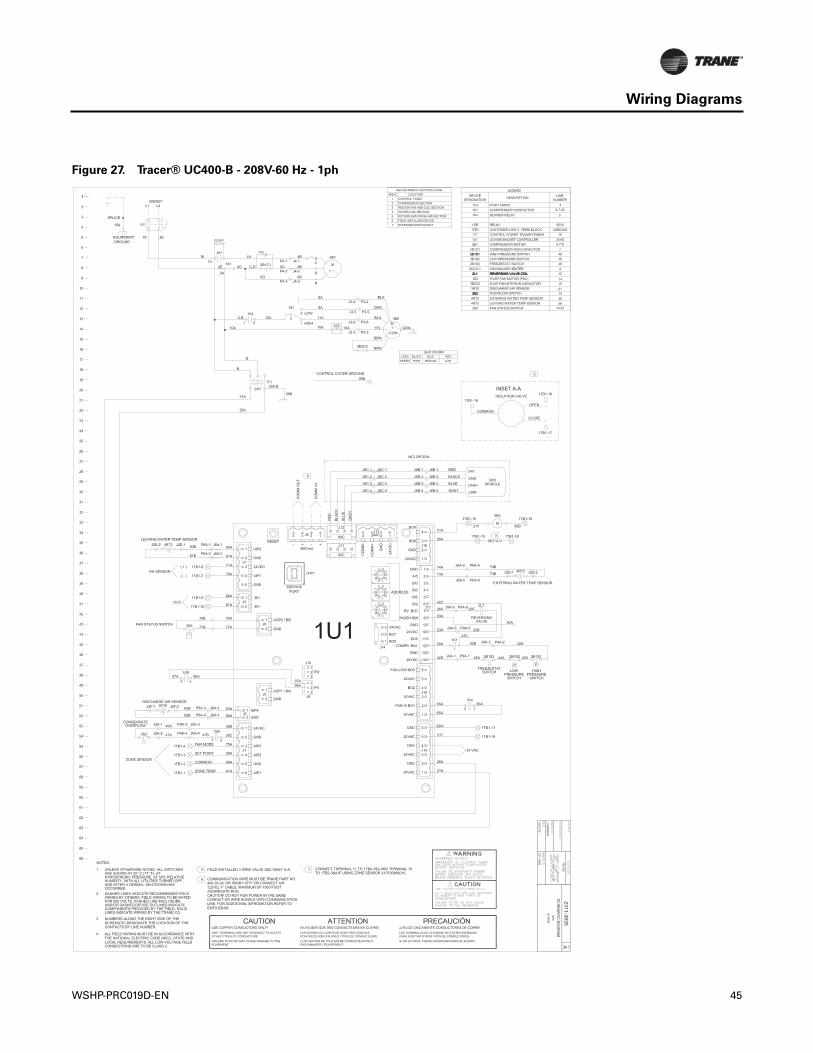
Wiring Diagrams
Figure 27. Tracer® UC400-B - 208V-60 Hz - 1ph
WSHP-PRC019D-EN 45
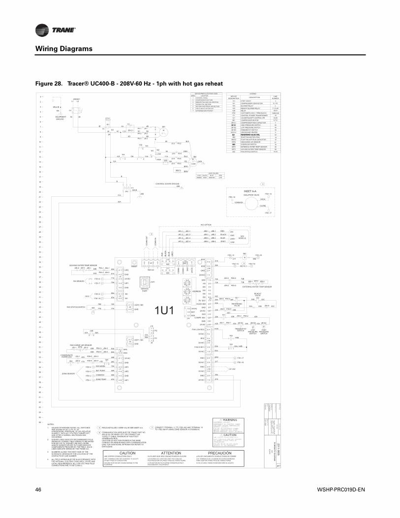
Wiring Diagrams
Figure 28. Tracer® UC400-B - 208V-60 Hz - 1ph with hot gas reheat
46 WSHP-PRC019D-EN
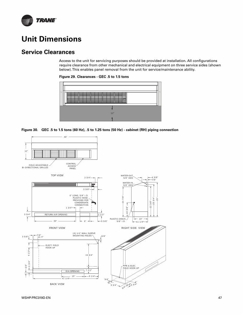
Unit Dimensions
Service Clearances
Access to the unit for servicing purposes should be provided at installation. All configurationsrequire clearance from other mechanical and electrical equipment on three service sides (shownbelow).This enables panel removal from the unit for service/maintenance ability.
Figure 29. Clearances - GEC .5 to 1.5 tons
12”
1"
1"
Figure 30. GEC .5 to 1.5 tons (60 Hz), .5 to 1.25 tons (50 Hz) - cabinet (RH) piping connection
48"
12"
CONTROLACCESS
PANEL
2 1/2"
6" LONG, 5/8" I.D.PLASTIC HOSE PROVIDED FOR
CONDENSATECONNECTION
3 3/8"
2 3/4"
5 5/8"33" 6"
3 3/4"
4"7/8"
1 3/
4"3/
4"
1 3/4"
4 3/8"7/8"
25"
23 3
/4"
22 3
/8"
10 3
/8"
21 7
/8"
10"11 1/4"
ELECT. FIELD HOOK-UP
(4) 1/4" WALL SLEEVEMOUNTING HOLES
RETURN-AIR OPENING
O/A OPENING
TOP VIEW
FRONT VIEW RIGHT SIDE VIEW
BACK VIEW
WATER-OUT5/8" ODS
WATER-IN5/8" ODS
PLASTIC DRAIN5/8" I.D.
FIELD ADJUSTABLEBI-DIRECTIONAL GRILLES
9 3/4"
3/4"
4 3/4"
3/4"
7 1/2"
15 3/4"
47 1/4"
PIPE & ELEC.FIELD HOOK-UP
15" 9 1/4"
4 1/
2"
3 5/8" 5/8"
WSHP-PRC019D-EN 47
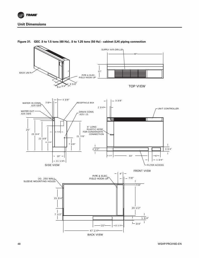
Unit Dimensions
Figure 31. GEC .5 to 1.5 tons (60 Hz), .5 to 1.25 tons (50 Hz) - cabinet (LH) piping connection
4"
3/4"9 5/8"
3/4"
47 1/4"
15"
7/8"
4"
1 3/4"
3/4"13 1/4"
PIPE & ELEC.FIELD HOOK-UP
7 1/2"
15 3/4"
(4) .250 WALL SLEEVE MOUNTING HOLES
FILTER ACCESS
33"
3 3/4"
FOR CONDENSATE
2 1/2"
CONNECTION
2 3/4"
3 3/8"
PLASTIC HOSE6" LONG
6"
1 3/4"
UNIT CONTROLLER
4 3/8"
21 7/8"
11 1/4"
DRAIN CONN..625 I.D.
10"
7 3/8"
23 3/4"
22 3/8"
25"
.625 ODS
WATER IN CONN..625 ODS
WATER OUT
7/8"
11 3/4"
4 7/8"
RECEPTACLE BOX
48"
12"
SUPPLY AIR GRILLE
SIDE VIEW
BACK VIEW
FRONT VIEW
BACK UNITPIPE & ELEC.
FIELD HOOK-UP
TOP VIEW
5 1/4"
20 1/2"
7/8"
48 WSHP-PRC019D-EN
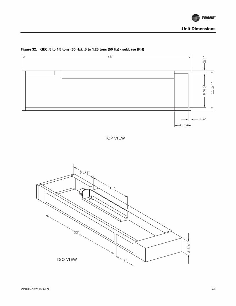
Unit Dimensions
Figure 32. GEC .5 to 1.5 tons (60 Hz), .5 to 1.25 tons (50 Hz) - subbase (RH)
4 3/4"
48"
9 1/4"
33"
6"
15"
9 5/
8"
3/4"
11 1
/4"
3 3/
4"
3/4"
TOP VIEW
ISO VIEW
WSHP-PRC019D-EN 49
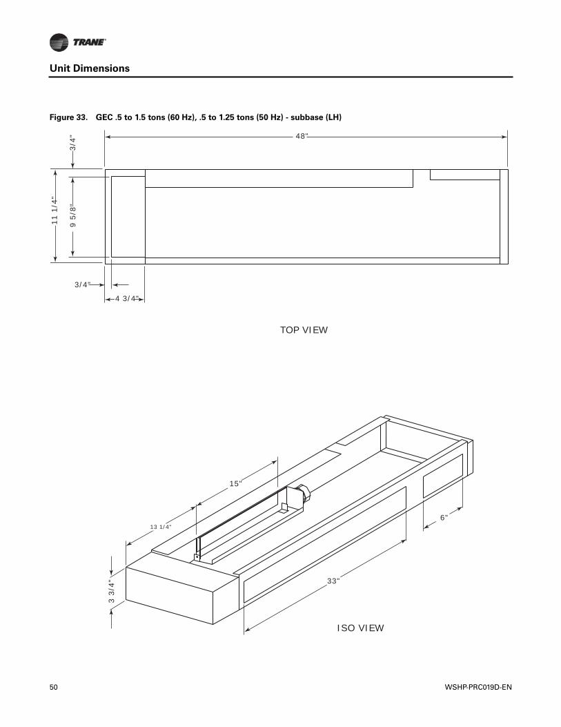
Unit Dimensions
Figure 33. GEC .5 to 1.5 tons (60 Hz), .5 to 1.25 tons (50 Hz) - subbase (LH)
4 3/4"
48"
13 1/4"
33"
6"
15"
9 5/
8"
3/4"
11 1
/4"
3 3/
4"
3/4"
TOP VIEW
ISO VIEW
50 WSHP-PRC019D-EN
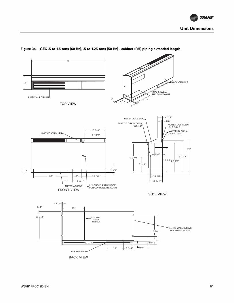
Unit Dimensions
Figure 34. GEC .5 to 1.5 tons (60 Hz), .5 to 1.25 tons (50 Hz) - cabinet (RH) piping extended length
18 7/8"9 1/4"
1"
1"
O/A OPENING15" 3/4"
1 3/4"
9 1/4"
(4).25 WALL SLEEVE MOUNTING HOLES
19"
3/8"
20 1/2"
10 1/2"
7/8"
4 3/8"
7 3/8"
21 7/8" 23 3/4"
22 3/8"
11 1/4"
25"
PLASTIC DRAIN CONN..625 I.D.
WATER IN CONN..625 O.D.S.
WATER OUT CONN.625 O.D.S.
16 3/8"
6 3/8"
RECEPTACLE BOX
UNIT CONTROLLER
33"
3 3/4"
FILTER ACCESS
2 1/2"
6" LONG PLASTIC HOSEFOR CONDENSATE CONN.
6"
1 3/4"
18 1/4"
17 3/4"
63"
12"
SUPPLY AIR GRILLE
PIPE & ELEC. FIELD HOOK-UP.
SIDE VIEWFRONT VIEW
BACK VIEW
TOP VIEW
BACK OF UNIT
20 5/8"
ELECTRIC FIELD
HOOKUP
62 1/4"
3/4"
7 1/2"
15 3/4"
WSHP-PRC019D-EN 51
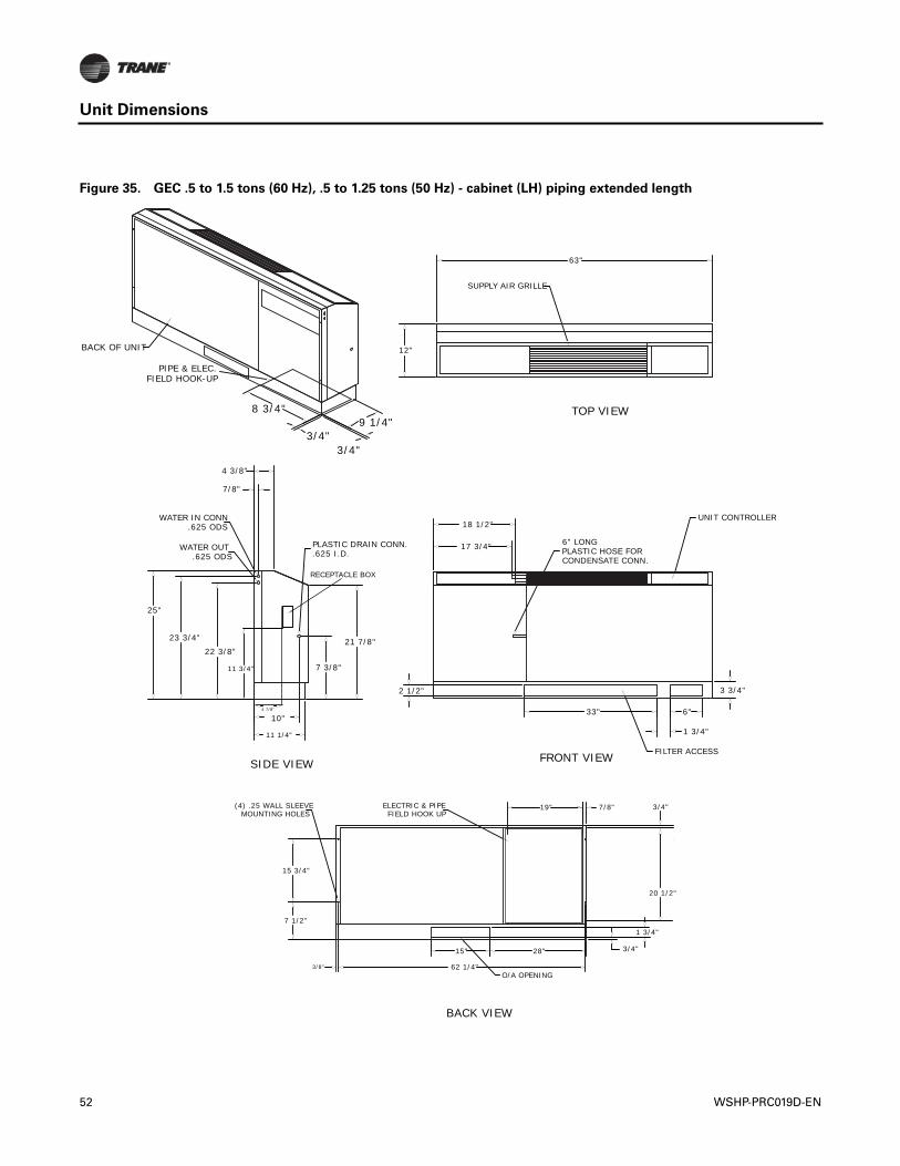
Unit Dimensions
Figure 35. GEC .5 to 1.5 tons (60 Hz), .5 to 1.25 tons (50 Hz) - cabinet (LH) piping extended length
ELECTRIC & PIPEFIELD HOOK UP
62 1/4"
15"
1 3/4"
3/4"
7/8"19"
20 1/2"
28"
O/A OPENING
7 1/2"
15 3/4"
(4) .25 WALL SLEEVEMOUNTING HOLES
4 3/8"
21 7/8"
11 1/4"
PLASTIC DRAIN CONN..625 I.D.
7 3/8"
23 3/4"
22 3/8"
25"
WATER OUT.625 ODS
WATER IN CONN.625 ODS
7/8"
6" LONG PLASTIC HOSE FOR CONDENSATE CONN.
33"
3 3/4"2 1/2"
18 1/2"
17 3/4"
FILTER ACCESS
6"
1 3/4"
UNIT CONTROLLER
63"
SUPPLY AIR GRILLE
12"
8 3/4"
3/4"
9 1/4"3/4"
SIDE VIEW
BACK VIEW
FRONT VIEW
BACK OF UNIT
PIPE & ELEC.FIELD HOOK-UP
TOP VIEW
11 3/4"
10"4 7/8"
RECEPTACLE BOX
3/8"
3/4"
52 WSHP-PRC019D-EN
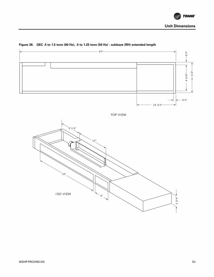
Unit Dimensions
Figure 36. GEC .5 to 1.5 tons (60 Hz), .5 to 1.25 tons (50 Hz) - subbase (RH) extended length
19 3/4"
63"
9 1/4"
33"
6"
15"
9 5/
8"
3/4"
11 1
/4"
3 3/
4"
3/4"
TOP VIEW
ISO VIEW
WSHP-PRC019D-EN 53
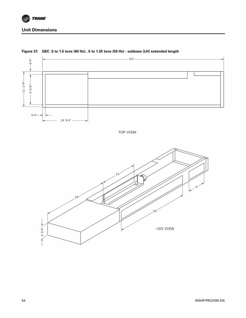
Unit Dimensions
Figure 37. GEC .5 to 1.5 tons (60 Hz), .5 to 1.25 tons (50 Hz) - subbase (LH) extended length
19 3/4"
63"
28"
33"
6"
15"
9 5/
8"
3/4"
11 1
/4"
3 3/
4"
3/4"
TOP VIEW
ISO VIEW
54 WSHP-PRC019D-EN
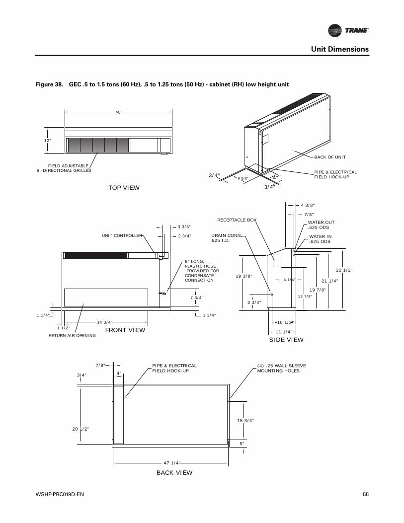
Unit Dimensions
Figure 38. GEC .5 to 1.5 tons (60 Hz), .5 to 1.25 tons (50 Hz) - cabinet (RH) low height unit
3/4"
3/4"
4"9 5/8"
10 1/2"
7/8"
4 3/8"
3 3/4"
19 3/8"21 1/4"
19 7/8"
11 1/4"
22 1/2"
.625 I.D.DRAIN CONN. WATER IN
.625 ODS
WATER OUT.625 ODS
13 7/8"
6 1/4"
RECEPTACLE BOX
PIPE & ELECTRICALFIELD HOOK-UP
47 1/4"
5"
15 3/4"
(4) .25 WALL SLEEVEMOUNTING HOLES4"
7/8"
34 3/4"
1 3/4"
RETURN AIR OPENING
1 1/4"
6" LONG,PLASTIC HOSE PROVIDED FORCONDENSATECONNECTION
7 3/4"
3 3/8"
2 3/4"UNIT CONTROLLER
48"
12"
FIELD ADJUSTABLEBI-DIRECTIONAL GRILLES
SIDE VIEW
BACK VIEW
FRONT VIEW
TOP VIEW
PIPE & ELECTRICALFIELD HOOK-UP
BACK OF UNIT
1 1/2"
3/4"
20 1/2"
WSHP-PRC019D-EN 55
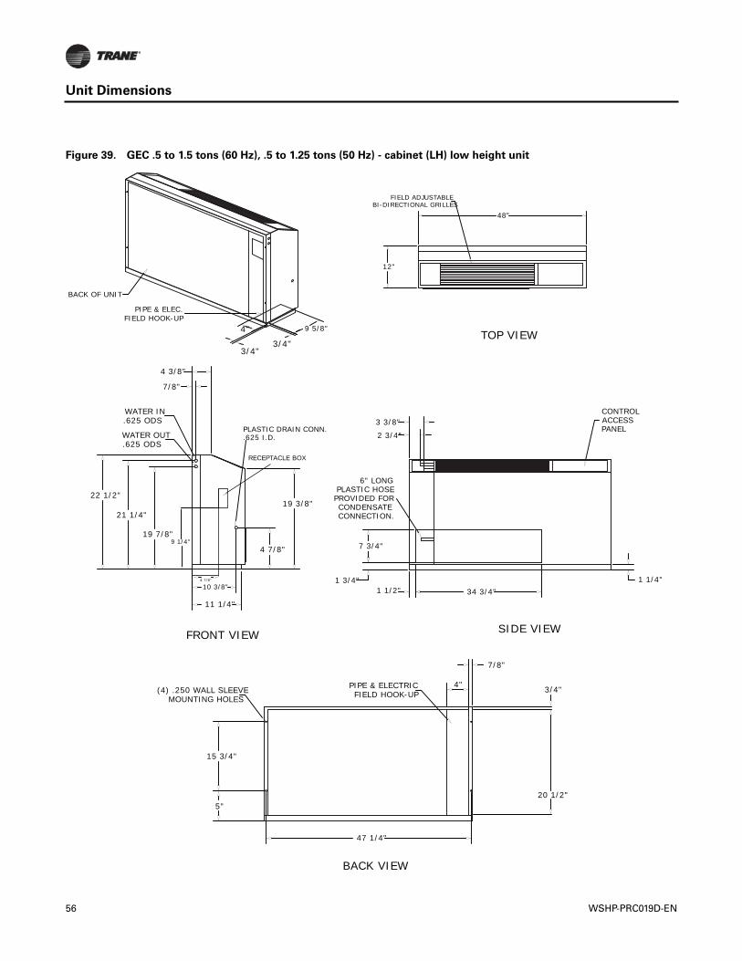
Unit Dimensions
Figure 39. GEC .5 to 1.5 tons (60 Hz), .5 to 1.25 tons (50 Hz) - cabinet (LH) low height unit
4"
3/4"3/4"
9 5/8"
47 1/4"
7/8"
4" 3/4"PIPE & ELECTRICFIELD HOOK-UP
5"
15 3/4"
(4) .250 WALL SLEEVEMOUNTING HOLES
48"
FIELD ADJUSTABLEBI-DIRECTIONAL GRILLES
12"
34 3/4"1 3/4" 1 1/4"
6" LONG PLASTIC HOSE
PROVIDED FORCONDENSATECONNECTION.
1 1/2"
7 3/4"
2 3/4"
3 3/8"CONTROLACCESSPANEL
4 3/8"
19 3/8"
11 1/4"
10 3/8"
4 7/8"
21 1/4"
19 7/8"
22 1/2"
.625 ODSWATER OUT
.625 ODSWATER IN
7/8"
SIDE VIEW
BACK VIEW
FRONT VIEW
TOP VIEW
PIPE & ELEC.FIELD HOOK-UP
BACK OF UNIT
4 7/8"
RECEPTACLE BOX
9 1/4"
PLASTIC DRAIN CONN..625 I.D.
20 1/2"
56 WSHP-PRC019D-EN
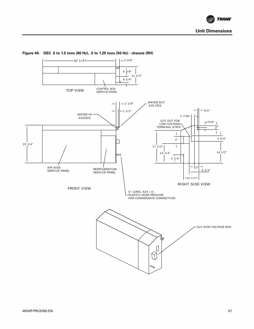
Unit Dimensions
Figure 40. GEC .5 to 1.5 tons (60 Hz), .5 to 1.25 tons (50 Hz) - chassis (RH)
3"
1 7/8"
3/4"
2 1/4"
12 1/4"
4"
14 1/2"
3 3/4"
2"
5/8"
17 1/4"
CUT OUT FORLOW VOLTAGE
TERMINAL STRIP
6 1/4"
10 1/2"
AIR SIDESERVICE PANEL
20 1/4"
REFRIGERATIONSERVICE PANEL
.625ODSWATER IN
2 1/8"
1 1/2"
6" LONG, 625 I.D.PLASTIC HOSE PROVIDEFOR CONDENSATE CONNECTION.
WATER OUT.625 ODS
42 1/4"
CONTROL BOXSERVICE PANEL
2 3/8"
11 1/2"6 3/8"
4 1/4"
2x4 HIGH VOLTAGE BOX
RIGHT SIDE VIEWFRONT VIEW
TOP VIEW
WSHP-PRC019D-EN 57
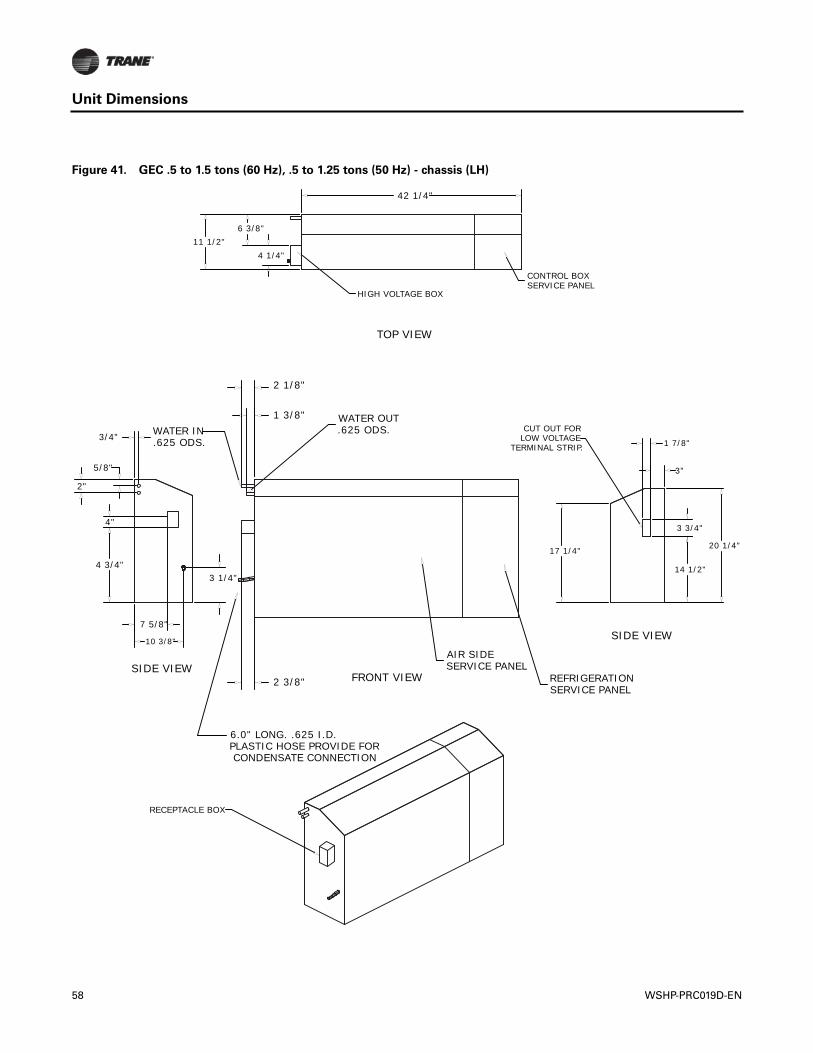
Unit Dimensions
Figure 41. GEC .5 to 1.5 tons (60 Hz), .5 to 1.25 tons (50 Hz) - chassis (LH)
3"
1 7/8"
17 1/4"
14 1/2"
3 3/4"
CUT OUT FORLOW VOLTAGE
TERMINAL STRIP.
3 1/4"4 3/4"
4"
3/4"
5/8"
2"
10 3/8"
7 5/8"
WATER OUT.625 ODS.
2 3/8"
1 3/8"
2 1/8"
CONDENSATE CONNECTIONPLASTIC HOSE PROVIDE FOR6.0" LONG. .625 I.D.
.625 ODS.WATER IN
AIR SIDESERVICE PANEL
REFRIGERATIONSERVICE PANEL
HIGH VOLTAGE BOX
42 1/4"
11 1/2"4 1/4"
6 3/8"
CONTROL BOXSERVICE PANEL
RECEPTACLE BOX
FRONT VIEW
TOP VIEW
SIDE VIEW
SIDE VIEW
20 1/4"
58 WSHP-PRC019D-EN
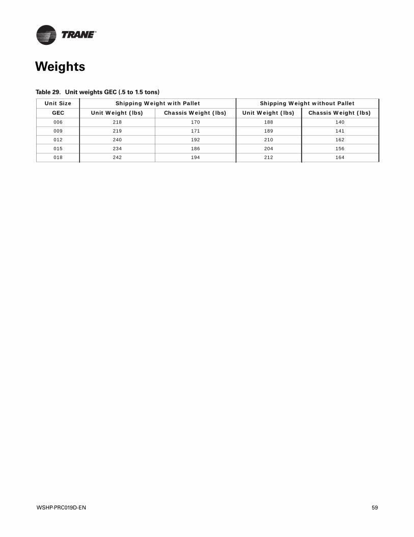
WSHP-PRC019D-EN 59
Weights
Table 29. Unit weights GEC (.5 to 1.5 tons)
Unit Size Shipping Weight with Pallet Shipping Weight without Pallet
GEC Unit Weight (lbs) Chassis Weight (lbs) Unit Weight (lbs) Chassis Weight (lbs)006 218 170 188 140
009 219 171 189 141
012 240 192 210 162
015 234 186 204 156
018 242 194 212 164
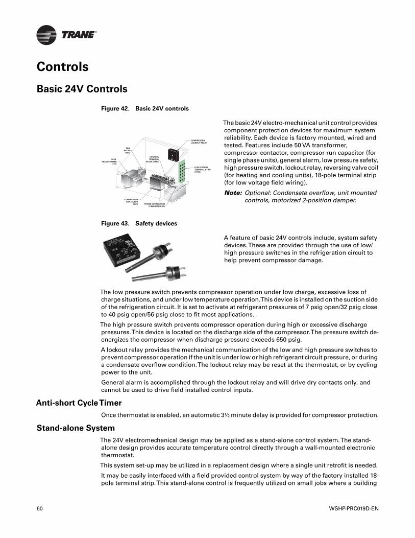
Controls
Basic 24V Controls
The low pressure switch prevents compressor operation under low charge, excessive loss ofcharge situations, and under low temperature operation.This device is installed on the suction sideof the refrigeration circuit. It is set to activate at refrigerant pressures of 7 psig open/32 psig closeto 40 psig open/56 psig close to fit most applications.
The high pressure switch prevents compressor operation during high or excessive dischargepressures.This device is located on the discharge side of the compressor.The pressure switch de-energizes the compressor when discharge pressure exceeds 650 psig.
A lockout relay provides the mechanical communication of the low and high pressure switches toprevent compressor operation if the unit is under low or high refrigerant circuit pressure, or duringa condensate overflow condition.The lockout relay may be reset at the thermostat, or by cyclingpower to the unit.
General alarm is accomplished through the lockout relay and will drive dry contacts only, andcannot be used to drive field installed control inputs.
Anti-short CycleTimer
Once thermostat is enabled, an automatic 3½ minute delay is provided for compressor protection.
Stand-alone System
The 24V electromechanical design may be applied as a stand-alone control system.The stand-alone design provides accurate temperature control directly through a wall-mounted electronicthermostat.
This system set-up may be utilized in a replacement design where a single unit retrofit is needed.
It may be easily interfaced with a field provided control system by way of the factory installed 18-pole terminal strip.This stand-alone control is frequently utilized on small jobs where a building
Figure 42. Basic 24V controls
The basic 24V electro-mechanical unit control providescomponent protection devices for maximum systemreliability. Each device is factory mounted, wired andtested. Features include 50 VA transformer,compressor contactor, compressor run capacitor (forsingle phase units), general alarm, low pressure safety,high pressure switch, lockout relay, reversing valve coil(for heating and cooling units), 18-pole terminal strip(for low voltage field wiring).
Note: Optional: Condensate overflow, unit mountedcontrols, motorized 2-position damper.
Figure 43. Safety devices
A feature of basic 24V controls include, system safetydevices.These are provided through the use of low/high pressure switches in the refrigeration circuit tohelp prevent compressor damage.
50VA
TRANSFORMER
(1T1)
FAN
RELAY
(1K4)
COMPRESSOR
CONTACTOR
(1K1)
CONTROL
TERMINAL
BLOCK (1TB2)
POWER CONNECTION
(FIELD HOOK-UP)
LOW VOLTAGE
TERMINAL STRIP
(1TB1)
COMPRESSOR
LOCKOUT RELAY
60 WSHP-PRC019D-EN
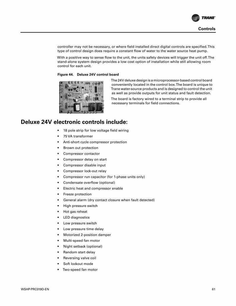
Controls
controller may not be necessary, or where field installed direct digital controls are specified.Thistype of control design does require a constant flow of water to the water source heat pump.
With a positive way to sense flow to the unit, the units safety devices will trigger the unit off.Thestand-alone system design provides a low cost option of installation while still allowing roomcontrol for each unit.
Deluxe 24V electronic controls include:
• 18 pole strip for low voltage field wiring
• 75 VA transformer
• Anti-short cycle compressor protection
• Brown out protection
• Compressor contactor
• Compressor delay on start
• Compressor disable input
• Compressor lock-out relay
• Compressor run capacitor (for 1-phase units only)
• Condensate overflow (optional)
• Electric heat and compressor enable
• Freeze protection
• General alarm (dry contact closure when fault detected)
• High pressure switch
• Hot gas reheat
• LED diagnostics
• Low pressure switch
• Low pressure time delay
• Motorized 2-position damper
• Multi-speed fan motor
• Night setback (optional)
• Random start delay
• Reversing valve coil
• Soft lockout mode
• Two-speed fan motor
Figure 44. Deluxe 24V control board
The 24V deluxe design is a microprocessor-based control boardconveniently located in the control box.The board is unique toTrane water-source products and is designed to control the unitas well as provide outputs for unit status and fault detection.
The board is factory wired to a terminal strip to provide allnecessary terminals for field connections.
WSHP-PRC019D-EN 61
Controls
Deluxe 24V features
Anti-short CycleTimer
The anti-short cycle timer provides a three minute time delay between compressor stop andcompressor restart.
Brown-out Protection
The brown-out protection function measures the input voltage to the controller and halts thecompressor operation. Once a brown-out situation has occurred, the anti-short cycle timer willbecome energized.The general fault contact will not be affected by this condition.The voltage willcontinue to be monitored until the voltage increases.The compressors will be enabled at this timeif all start-up time delays have expired, and all safeties have been satisfied.
Compressor Disable
The compressor disable relay provides a temporary disable in compressor operation.The signalwould be provided from a water loop controller in the system. It would disable the compressorbecause of low water flow, peak limiting or if the unit goes into an unoccupied state. Once thecompressor has been disabled, the anti-short cycle time period will begin. Once the compressordisable signal is no longer present, and all safeties are satisfied, the control will allow thecompressor to restart.
Diagnostics
Three LEDs (light emitting diodes) are provided for indicating the operating mode of the controller.See the unit IOM for diagnostics or troubleshooting through the use of the LEDs.
Generic Relay
The generic relay is provided for field use. Night setback or pump restart are two options that maybe wired to the available relay.
A 24 Vac signal will energize the relay coil on terminals R1 and R2.Terminals C (common), NO(normally open), and NC (normally closed) will be provided for the relay contacts.
Random Start
The random start relay provides a time delay start-up of the compressor when cycling in theoccupied mode. A new start delay time between 3 and 10 seconds is applied each time power isenabled to the unit.
Safety Control
The deluxe controller receives separate input signals from the refrigerant high pressure switch, lowsuction pressure switch, and condensate overflow.
In a high pressure situation, the compressor contactor is de-energized, which suspendscompressor operation.The control will go into soft lockout mode initializing a three minute timedelay and a random start of 3 to 10 second time delays. Once these delays have expired, the unitwill be allowed to run. If a high pressure situation occurs within one hour of the first situation, thecontrol will be placed into a manual lockout mode, halting compressor operation, and initiating thegeneral alarm.
In a low temperature situation, the low pressure switch will transition open after the compressorstarts. If the switch is open for 45 seconds during compressor start, the unit will go into soft lockoutmode initializing a three minute time delay and a random start of 3 to 10 second time delays. Oncethese delays have expired, the unit will be allowed to run. If the low pressure situation occurs againwithin 30 minutes, and the device is open for more than 45 seconds, the control will be placed intoa manual lockout mode, halting compressor operation, and initiating the general alarm.
In a condensate overflow situation, the control will go into manual lockout mode, haltingcompressor operation, and initiating the general alarm.
62 WSHP-PRC019D-EN
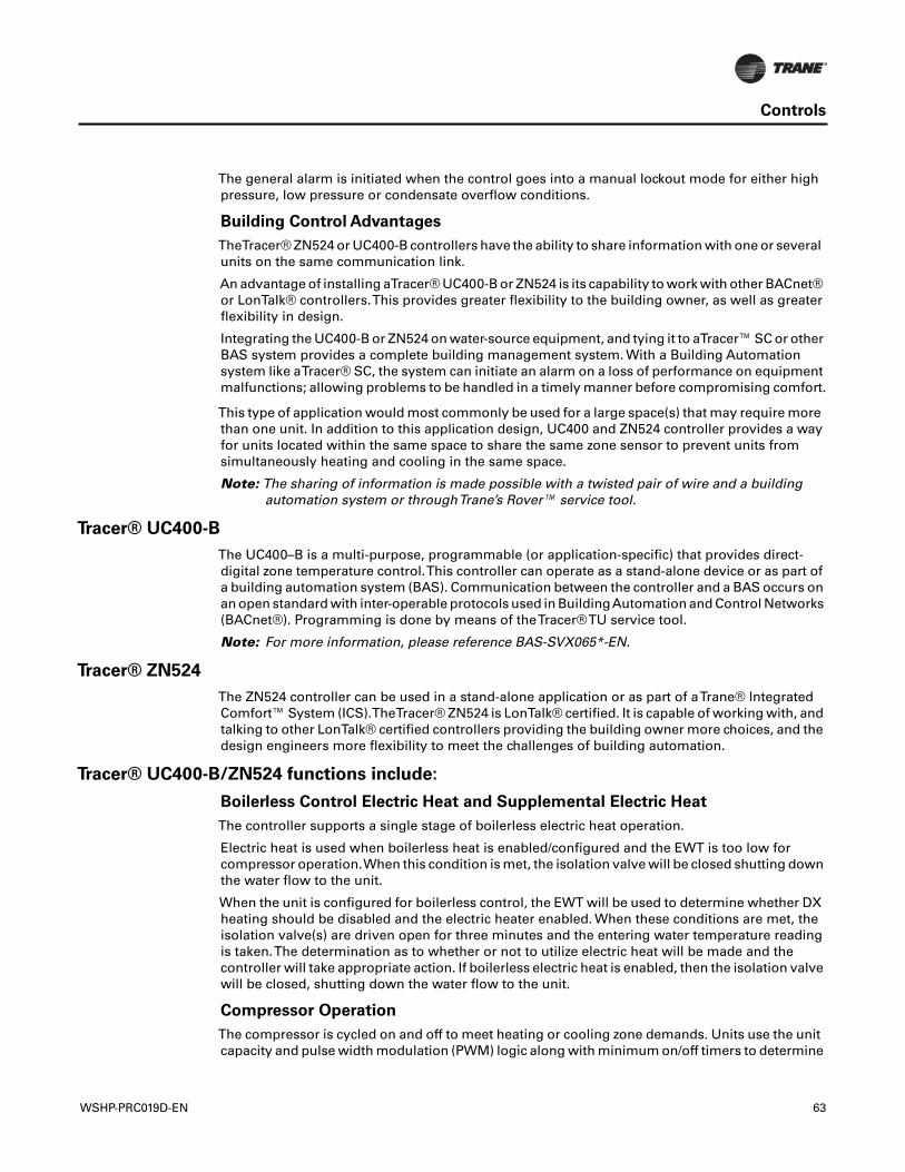
Controls
The general alarm is initiated when the control goes into a manual lockout mode for either highpressure, low pressure or condensate overflow conditions.
Building Control Advantages
TheTracer® ZN524 or UC400-B controllers have the ability to share information with one or severalunits on the same communication link.
An advantage of installing aTracer® UC400-B or ZN524 is its capability to work with other BACnet®or LonTalk® controllers.This provides greater flexibility to the building owner, as well as greaterflexibility in design.
Integrating the UC400-B or ZN524 on water-source equipment, and tying it to aTracer™ SC or otherBAS system provides a complete building management system. With a Building Automationsystem like aTracer® SC, the system can initiate an alarm on a loss of performance on equipmentmalfunctions; allowing problems to be handled in a timely manner before compromising comfort.
This type of application would most commonly be used for a large space(s) that may require morethan one unit. In addition to this application design, UC400 and ZN524 controller provides a wayfor units located within the same space to share the same zone sensor to prevent units fromsimultaneously heating and cooling in the same space.
Note: The sharing of information is made possible with a twisted pair of wire and a buildingautomation system or throughTrane’s Rover™ service tool.
Tracer® UC400-B
The UC400–B is a multi-purpose, programmable (or application-specific) that provides direct-digital zone temperature control.This controller can operate as a stand-alone device or as part ofa building automation system (BAS). Communication between the controller and a BAS occurs onan open standard with inter-operable protocols used in BuildingAutomation and Control Networks(BACnet®). Programming is done by means of theTracer®TU service tool.
Note: For more information, please reference BAS-SVX065*-EN.
Tracer® ZN524
The ZN524 controller can be used in a stand-alone application or as part of aTrane® IntegratedComfort™ System (ICS).TheTracer® ZN524 is LonTalk® certified. It is capable of working with, andtalking to other LonTalk® certified controllers providing the building owner more choices, and thedesign engineers more flexibility to meet the challenges of building automation.
Tracer® UC400-B/ZN524 functions include:
Boilerless Control Electric Heat and Supplemental Electric Heat
The controller supports a single stage of boilerless electric heat operation.
Electric heat is used when boilerless heat is enabled/configured and the EWT is too low forcompressor operation.When this condition is met, the isolation valve will be closed shutting downthe water flow to the unit.
When the unit is configured for boilerless control, the EWT will be used to determine whether DXheating should be disabled and the electric heater enabled. When these conditions are met, theisolation valve(s) are driven open for three minutes and the entering water temperature readingis taken.The determination as to whether or not to utilize electric heat will be made and thecontroller will take appropriate action. If boilerless electric heat is enabled, then the isolation valvewill be closed, shutting down the water flow to the unit.
Compressor Operation
The compressor is cycled on and off to meet heating or cooling zone demands. Units use the unitcapacity and pulse width modulation (PWM) logic along with minimum on/off timers to determine
WSHP-PRC019D-EN 63
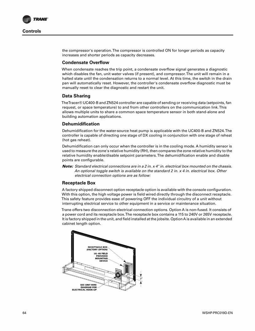
Controls
the compressor's operation.The compressor is controlled ON for longer periods as capacityincreases and shorter periods as capacity decreases.
Condensate Overflow
When condensate reaches the trip point, a condensate overflow signal generates a diagnosticwhich disables the fan, unit water valves (if present), and compressor.The unit will remain in ahalted state until the condensation returns to a normal level. At this time, the switch in the drainpan will automatically reset. However, the controller's condensate overflow diagnostic must bemanually reset to clear the diagnostic and restart the unit.
Data Sharing
TheTracer® UC400-B and ZN524 controller are capable of sending or receiving data (setpoints, fanrequest, or space temperature) to and from other controllers on the communication link.Thisallows multiple units to share a common space temperature sensor in both stand-alone andbuilding automation applications.
Dehumidification
Dehumidification for the water-source heat pump is applicable with the UC400-B and ZN524.Thecontroller is capable of directing one stage of DX cooling in conjunction with one stage of reheat(hot gas reheat).
Dehumidification can only occur when the controller is in the cooling mode. A humidity sensor isused to measure the zone's relative humidity (RH), then compares the zone relative humidity to therelative humidity enable/disable setpoint parameters.The dehumidification enable and disablepoints are configurable.
Note: Standard electrical connections are in a 2 in. x 4" in. electrical box mounted on the chassis.An optional toggle switch is available on the standard 2 in. x 4 in. electrical box. Otherelectrical connection options are as follow:
Receptacle Box
A factory shipped disconnect option receptacle option is available with the console configuration.With this option, the high voltage power is field wired directly through the disconnect receptacle.This safety feature provides ease of powering OFF the individual circuitry of a unit withoutinterrupting electrical service to other equipment in a service or maintenance situation.
Trane offers two disconnection electrical connection options. Option A is non-fused. It consists ofa power cord and its receptacle box.The receptacle box contains a 115 to 240V or 265V receptacle.It is factory shipped in the unit, and field installed at the jobsite. OptionA is available in an extendedcabinet length option.
64 WSHP-PRC019D-EN
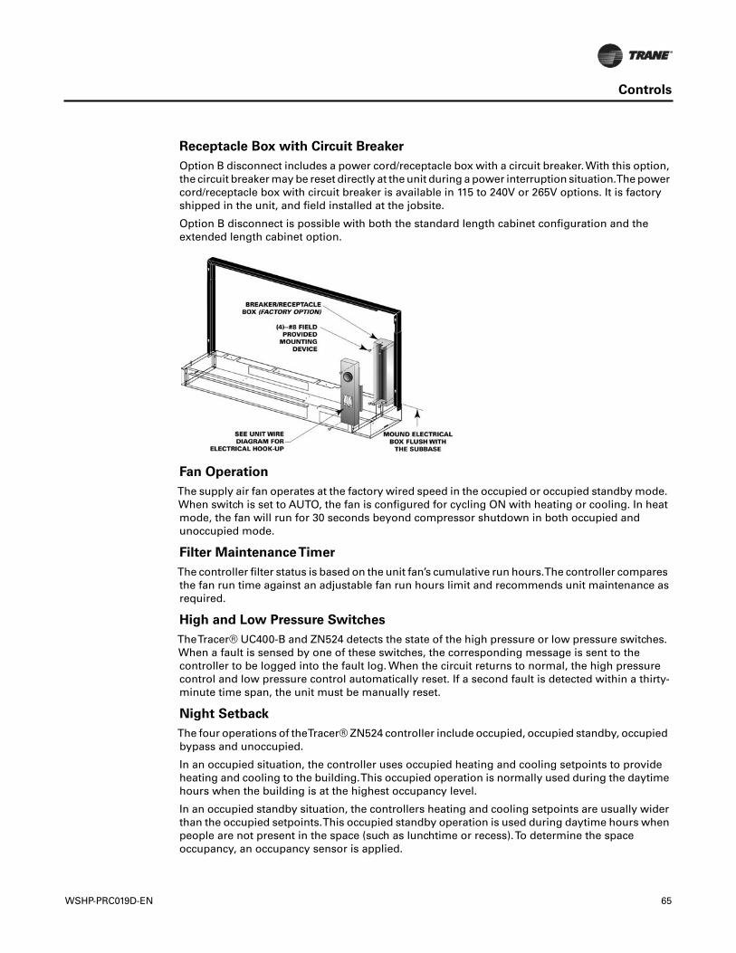
Controls
Receptacle Box with Circuit Breaker
Option B disconnect includes a power cord/receptacle box with a circuit breaker.With this option,the circuit breaker may be reset directly at the unit during a power interruption situation.The powercord/receptacle box with circuit breaker is available in 115 to 240V or 265V options. It is factoryshipped in the unit, and field installed at the jobsite.
Option B disconnect is possible with both the standard length cabinet configuration and theextended length cabinet option.
Fan Operation
The supply air fan operates at the factory wired speed in the occupied or occupied standby mode.When switch is set to AUTO, the fan is configured for cycling ON with heating or cooling. In heatmode, the fan will run for 30 seconds beyond compressor shutdown in both occupied andunoccupied mode.
Filter MaintenanceTimer
The controller filter status is based on the unit fan’s cumulative run hours.The controller comparesthe fan run time against an adjustable fan run hours limit and recommends unit maintenance asrequired.
High and Low Pressure Switches
TheTracer® UC400-B and ZN524 detects the state of the high pressure or low pressure switches.When a fault is sensed by one of these switches, the corresponding message is sent to thecontroller to be logged into the fault log. When the circuit returns to normal, the high pressurecontrol and low pressure control automatically reset. If a second fault is detected within a thirty-minute time span, the unit must be manually reset.
Night Setback
The four operations of theTracer® ZN524 controller include occupied, occupied standby, occupiedbypass and unoccupied.
In an occupied situation, the controller uses occupied heating and cooling setpoints to provideheating and cooling to the building.This occupied operation is normally used during the daytimehours when the building is at the highest occupancy level.
In an occupied standby situation, the controllers heating and cooling setpoints are usually widerthan the occupied setpoints.This occupied standby operation is used during daytime hours whenpeople are not present in the space (such as lunchtime or recess).To determine the spaceoccupancy, an occupancy sensor is applied.
WSHP-PRC019D-EN 65
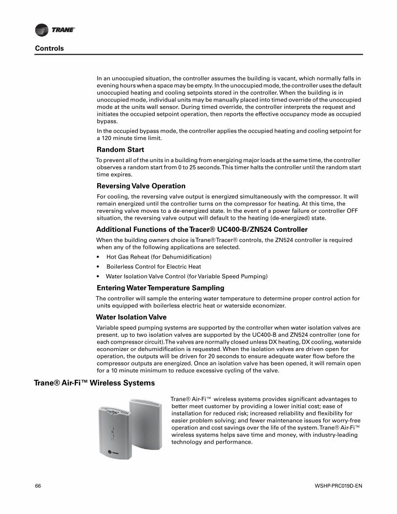
Controls
In an unoccupied situation, the controller assumes the building is vacant, which normally falls inevening hours when a space may be empty. In the unoccupied mode, the controller uses the defaultunoccupied heating and cooling setpoints stored in the controller. When the building is inunoccupied mode, individual units may be manually placed into timed override of the unoccupiedmode at the units wall sensor. During timed override, the controller interprets the request andinitiates the occupied setpoint operation, then reports the effective occupancy mode as occupiedbypass.
In the occupied bypass mode, the controller applies the occupied heating and cooling setpoint fora 120 minute time limit.
Random Start
To prevent all of the units in a building from energizing major loads at the same time, the controllerobserves a random start from 0 to 25 seconds.This timer halts the controller until the random starttime expires.
Reversing Valve Operation
For cooling, the reversing valve output is energized simultaneously with the compressor. It willremain energized until the controller turns on the compressor for heating. At this time, thereversing valve moves to a de-energized state. In the event of a power failure or controller OFFsituation, the reversing valve output will default to the heating (de-energized) state.
Additional Functions of theTracer® UC400-B/ZN524 Controller
When the building owners choice isTrane®Tracer® controls, the ZN524 controller is requiredwhen any of the following applications are selected.
• Hot Gas Reheat (for Dehumidification)
• Boilerless Control for Electric Heat
• Water Isolation Valve Control (for Variable Speed Pumping)
Entering WaterTemperature Sampling
The controller will sample the entering water temperature to determine proper control action forunits equipped with boilerless electric heat or waterside economizer.
Water Isolation Valve
Variable speed pumping systems are supported by the controller when water isolation valves arepresent. up to two isolation valves are supported by the UC400-B and ZN524 controller (one foreach compressor circuit).The valves are normally closed unless DX heating, DX cooling, watersideeconomizer or dehumidification is requested. When the isolation valves are driven open foroperation, the outputs will be driven for 20 seconds to ensure adequate water flow before thecompressor outputs are energized. Once an isolation valve has been opened, it will remain openfor a 10 minute minimum to reduce excessive cycling of the valve.
Trane® Air-Fi™ Wireless Systems
Trane® Air-Fi™ wireless systems provides significant advantages tobetter meet customer by providing a lower initial cost; ease ofinstallation for reduced risk; increased reliability and flexibility foreasier problem solving; and fewer maintenance issues for worry-freeoperation and cost savings over the life of the system.Trane® Air-Fi™wireless systems helps save time and money, with industry-leadingtechnology and performance.
66 WSHP-PRC019D-EN
Controls
Air-Fi™ Wireless Communications Interface (WCI)
The Air-Fi™Wireless Communications Interface (WCI) enables wireless communications betweensystem controls, unit controls, and wireless sensors forTrane® control products that use theBACnet® protocol.TheWCI replaces the need for communications wire in all system applications.
The WCI is available in three configurations:
• The universal model is the most common. It installs the same as a wired zone sensor in indoorapplications.
• The outdoor model is housed in an enclosure suitable for outdoor environments. It is usuallyused on equipment above the roof deck.
• The flush mount model is used on fan coils, blower coils, and unit ventilators.
Air-Fi™ Wireless Communications Sensor (WCS)
The Air-Fi™Wireless Communications Sensor (WCS) is compatible with anyTrane® controller thatuses a WCI.The WCS provides the same functions as many currently availableTrane® wiredsensors. No further software or hardware is necessary for site evaluation, installation, ormaintenance. Space temperature is standard on all models. (A service tool cannot be connectedto aTrane® wireless sensor.)
Three WCS models are available:
• Digital display (WCS-SD) model
• Base (WCS-SB) model has no exposed display or user interface
• 2% relative humidity sensor module (WCS-SH), which can be field installed inside either theWCS-SD or WCS-SB.
In most applications, one WCS-SD or WCS-SB sensor will be used per WCI acting as a router.However, up to 6 WCS-SD or WCS-SB sensors can be associated to a single equipment controlleror BCI.
Compatibility with Previous Generation Wireless Zone Products
Our previous line of wireless zone sensors (WZS, WTS, and WDS) are not compatible with the Air-Fi™ Wireless Communications Interface (WCI).
The new Air-Fi™Wireless Communications Sensor (WCS) are compatible with oldWCIs that haveupdated firmware.
Wired Zone Sensors
Wired zone sensors can be used with Air-Fi™ wireless systems.
WSHP-PRC019D-EN 67
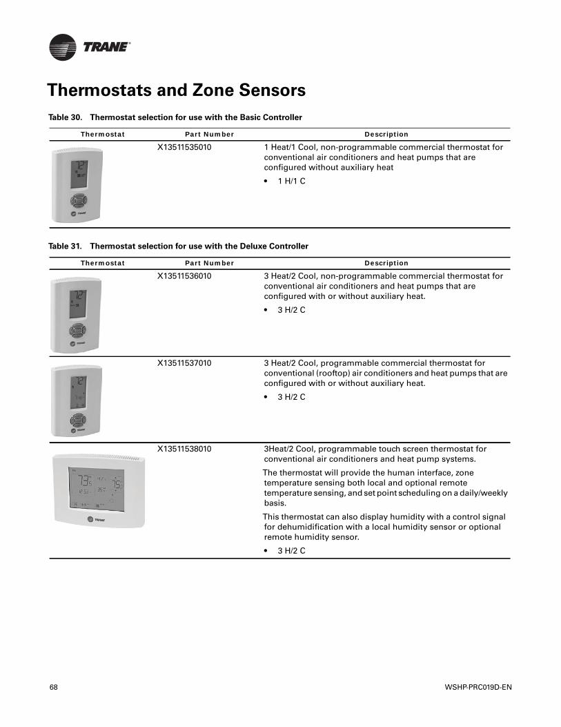
Thermostats and Zone Sensors
Table 30. Thermostat selection for use with the Basic Controller
Thermostat Part Number Description
X13511535010 1 Heat/1 Cool, non-programmable commercial thermostat forconventional air conditioners and heat pumps that areconfigured without auxiliary heat
• 1 H/1 C
Table 31. Thermostat selection for use with the Deluxe Controller
Thermostat Part Number Description
X13511536010 3 Heat/2 Cool, non-programmable commercial thermostat forconventional air conditioners and heat pumps that areconfigured with or without auxiliary heat.
• 3 H/2 C
X13511537010 3 Heat/2 Cool, programmable commercial thermostat forconventional (rooftop) air conditioners and heat pumps that areconfigured with or without auxiliary heat.
• 3 H/2 C
X13511538010 3Heat/2 Cool, programmable touch screen thermostat forconventional air conditioners and heat pump systems.
The thermostat will provide the human interface, zonetemperature sensing both local and optional remotetemperature sensing, and set point scheduling on a daily/weeklybasis.
This thermostat can also display humidity with a control signalfor dehumidification with a local humidity sensor or optionalremote humidity sensor.
• 3 H/2 C
68 WSHP-PRC019D-EN
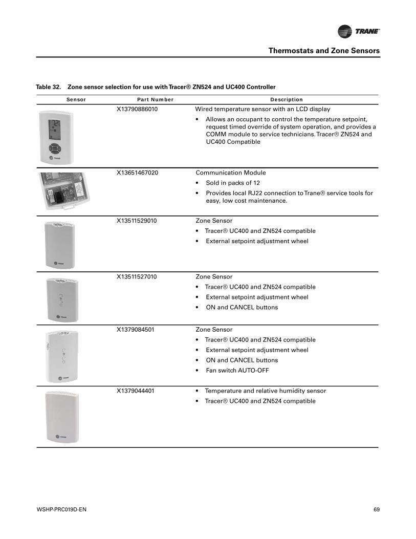
Thermostats and Zone Sensors
Table 32. Zone sensor selection for use withTracer® ZN524 and UC400 Controller
Sensor Part Number Description
X13790886010 Wired temperature sensor with an LCD display
• Allows an occupant to control the temperature setpoint,request timed override of system operation, and provides aCOMM module to service technicians.Tracer® ZN524 andUC400 Compatible
X13651467020 Communication Module
• Sold in packs of 12
• Provides local RJ22 connection toTrane® service tools foreasy, low cost maintenance.
X13511529010 Zone Sensor
• Tracer® UC400 and ZN524 compatible
• External setpoint adjustment wheel
X13511527010 Zone Sensor
• Tracer® UC400 and ZN524 compatible
• External setpoint adjustment wheel
• ON and CANCEL buttons
X1379084501 Zone Sensor
• Tracer® UC400 and ZN524 compatible
• External setpoint adjustment wheel
• ON and CANCEL buttons
• Fan switch AUTO-OFF
X1379044401 • Temperature and relative humidity sensor
• Tracer® UC400 and ZN524 compatible
WSHP-PRC019D-EN 69
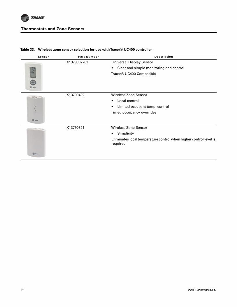
Thermostats and Zone Sensors
Table 33. Wireless zone sensor selection for use withTracer® UC400 controller
Sensor Part Number Description
X1379082201 Universal Display Sensor
• Clear and simple monitoring and control
Tracer® UC400 Compatible
X13790492 Wireless Zone Sensor
• Local control
• Limited occupant temp. control
Timed occupancy overrides
X13790821 Wireless Zone Sensor
• Simplicity
Eliminates local temperature control when higher control level isrequired
70 WSHP-PRC019D-EN
Mechanical Specifications
General
Equipment shall be completely assembled, piped, internally wired and test operated at the factory.It shall be both ETL and ISO-AHRI 13256-1 listed and labeled prior to leaving the factory. Serviceand caution area labels shall also be placed on the unit in their appropriate locations.
Air-to-Refrigerant Coil
Internally finned, 3/8-inch copper tubes mechanically bonded to a configured aluminum plate finas standard. Coils are leak tested at the factory to ensure the pressure integrity.The coil shall beleak tested to 450 psig and pressure tested to 650 psig.The tubes are to be completely evacuatedof air and correctly charged with proper volume of refrigerant prior to shipment.
The refrigerant coil distributor assembly shall be of orifice style with round copper distributortubes.The tubes are sized consistently with the capacity of the coil. Suction header is fabricatedfrom rounded copper pipe.
A thermostatic expansion valve is factory selected and installed for a wide range of control.
Ball Valves
Ball valves are field installed between the unit and the supply and return lines of the loop to stopwater flow to the unit in a maintenance or service situation.
Cabinet
The cabinet shall be constructed of sturdy galvanized steel, with exposed edges rounded.The steelshall include electrostatic powder paint in three attractive colors for an appliance grade finish.Service to the refrigerant and controls shall be provided through a single access panel at the frontof the unit chassis. Insulation for the internal parts and surfaces exposed to the conditioned airstream shall be made of moisture resistant insulation.
The insulation shall be ½-inch thick dual density bonded glass fiber.The exposed side shall be ahigh density erosion proof material suitable for use in airstreams up to 4500 feet per minute (FPM).Insulation shall meet the Underwriters' Laboratories Fire Hazard Classification:
• Flame spread = 25
• Smoke developed = 50
Access for inspection and cleaning of the unit drain pan, coils and fan section shall be provided.The unit shall be installed for proper access. Procedures for proper access inspection and cleaningof the unit shall be included in the maintenance manual.
Drain Pan
The drain pan shall be constructed of corrosion resistant material and insulated to preventsweating.The bottom of the drain pan shall be sloped on two planes which pitches the condensateto the drain connection.
Electric Heat (option)
The electric heat option (boilerless for the heat pump version) shall be factory wired and tested.It shall be composed of a nichrome open wire coil designed for 2-kW per unit ton. It shall consistof a single stage of electric heat used as a primary heating source when compressor lockout hasoccurred due to the entering water temperature falling below 55°F in a boilerless situation.
Electrical
The factory tested and installed control box shall contain all necessary devices to allow heating andcooling operation of the equipment to occur from a remote wall thermostat or zone sensor.Thesedevices shall be as follows:
• 24VAC Energy Limiting Class II, 50VA breaker with external fuse or 75VA with a circuit breaker
• 24 VAC contactor for compressor control
WSHP-PRC019D-EN 71
Mechanical Specifications
• 18 pole terminal strip located inside the control box behind the service access panel.Thisterminal strip shall be used for low voltage (thermostat/zone sensor) connections.
• An electrically operated safety lockout relay shall help prevent cycling of the compressor duringadverse conditions of operation.This device shall be reset either at the remote thermostat/zonesensor, or by cycling power to the unit.
• A high pressure switch shall help protect the compressor against operation at refrigerantsystem pressure in excess of 650 psig.
• A low pressure switch shall help prevent compressor operation under low charge orcatastrophic loss of charge situations.
• Factory installed wire harness shall be available for the Basic, Deluxe,Tracer® ZN524, UC400-B andTerminal Unit Control packages.
Fans
The fans shall be placed in a blow-through configuration.They shall be constructed of corrosionresistant galvanized material.
Filters
One inch throwaway filters shall be standard and factory installed.The filters shall have an averageresistance of 76-percent and dust holding capacity of 26-grams per square foot.
Hoses (option)
Hoses shall consist of a stainless steel outer braid with an inner core of tube made of a nontoxicsynthetic polymar material.The hoses shall be suitable for water temperatures ranging between33°F and 211°F without the use of glycol.
Automatic Flow Devices (option)
The automatic self-balancing device shall automatically limit the rate of flow to within 10-percentof the specified amount, over a 40 to 1 differential pressure operating range of 2 to 80 PSID.Theoperational temperature shall be rated from fluid freezing, to 225°F.
The valve body shall be suited for working pressures of 400 PSIG.The valve internal core shallconsist of one or more high temperature elastomeric diaphragms and precision orifice withsculptured orifice seat.
Dual pressure/temperature test ports shall be standard for verifying the pressure differential andsystem temperature.
Motors
The motors shall be a multi-speed permanent split capacitor with thermal overload protection. Ahigh and low switching device shall be provided for all units and accessible behind the hingedcontrol door.The motor shall contain a quick-disconnect plug and permanently lubricated bearing.
Pump Module (field installed accessory)
The pump module shall consist of either a single or dual 1/6 HP bronze pump and a brass 3-wayshut-off valve. Cast iron pumps are also acceptable.The pump module kits shall contain thenecessary components for the installation, operation and maintenance of the water circuit of aclosed-loop distributed pumping application.
Reheat Coil (option)
Dehumidification shall be provided through a hot gas reheat option.The coil shall consist of coppertubes mechanically expanded into evenly spaced aluminum fins. All coils are to be proof and leaktested.The proof must be performed at 1.5 times the maximum operating pressure and the leaktest at the maximum operating pressure. In addition, the tubes are to be completely evacuated ofair to check for leaks in a vacuum.
72 WSHP-PRC019D-EN
Mechanical Specifications
Refrigerant Metering
The equipment shall be provided with a (TXV) thermal expansion valve to allow operation of theunit with entering fluid temperature from 25°F to 120°F.
Refrigeration System Compressor
The unit shall include a general efficiency rotary compressor. External vibration isolation shall beprovided by rubber mounting devices located underneath the mounting base of the compressor.A second isolation of the refrigeration assembly shall be supported under the compressormounting base.
Thermal overload protection shall be provided. Protection shall be provided against excessivedischarge pressure operation by means of a high pressure switch. Loss of charge protection shallbe provided by a low pressure switch.
RefrigerantTubing
The refrigerant tubing shall be of 99% pure copper.This system shall be free from contaminantsand conditions such as drilling fragments, dirt and oil. All refrigerant and water lines shall beinsulated with an elastomeric insulation that has a 3/8-inch thick wall where ever air is introducedto the assembly.
Sound Attenuation
Sound attenuation shall be applied as a standard feature in the product design.
The sound reduction package shall include a vibration isolation to the compressor and water-to-refrigerant coil, a second stage of vibration isolation to the compressor base pan, heavy gauge baseassembly, insulated metal compressor enclosure, and maximum sized return-air opening and filtersizing.
The unit shall be tested and rated in accordance with AHRI 350.
Water-to-Refrigerant Heat Exchanger
The water-to-refrigerant heat exchanger shall be of a high quality co-axial coil for maximum heattransfer.The copper or optional cupro-nickel coil shall be deeply fluted to enhance heat transfer andminimize fouling and scaling.The coil has a working pressure of 400 psig on the water side and650 psig on the refrigerant side.The factory shall provide rubber isolation to the heat exchangingdevice to enhance sound attenuation.
WSHP-PRC019D-EN 73
We are committed to using environmentally
conscious print practices that reduce waste.
Ingersoll Rand (NYSE:IR) advances the quality of life by creating comfortable, sustainable and efficient environments.Our people and our family of brands—including Club Car®, Ingersoll Rand®,Thermo King® andTrane®—work togetherto enhance the quality and comfort of air in homes and buildings; transport and protect food and perishables; andincrease industrial productivity and efficiency. We are a global business committed to a world of sustainable progressand enduring results. For more information, visit www.ingersollrand.com.
Ingersoll Rand has a policy of continuous product and product data improvement and reserves the right to change design and specifications without notice.
The AHRI Certified mark indicates Ingersoll Rand’s participation in the AHRI Certification program. For verification of individual certified products, go to
www.ahridirectory.org.
© 2016 Ingersoll Rand All rights reserved
WSHP-PRC019D-EN 25 May 2016
Supersedes WSHP-PRC19-EN (24 Apr 2013)