Embed Size (px)
Citation preview
WAVE OPTICS & LASER
WAVE OPTICS & LASERInterference
Air-Wedge – Theory and Applications
LASER
Types of LASER
Nd:YAG LASER, CO2 LASER, Semiconductor LASER (homojuntion)
Application : Holography
Fiber Optics – Principle
Types of Optical Fibers
Fiber Optics Communication System
WAVE OPTICS
Wave Optics deals with different optical phenomena
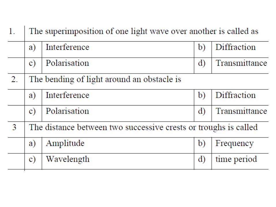
Interference
Diffraction
Polarisation
INTERFERENCE
A phenomenon in which two waves superpose to form a
resultant wave of greater amplitude or lower amplitude
Interference effects can be observed with all types of
waves
Light waves
Radio waves
Acoustic waves
Surface water waves
Matter waves
Path difference and phase difference will
be meaningful for waves of same
frequency
They are used to determine constructive
and destructive interference in waves
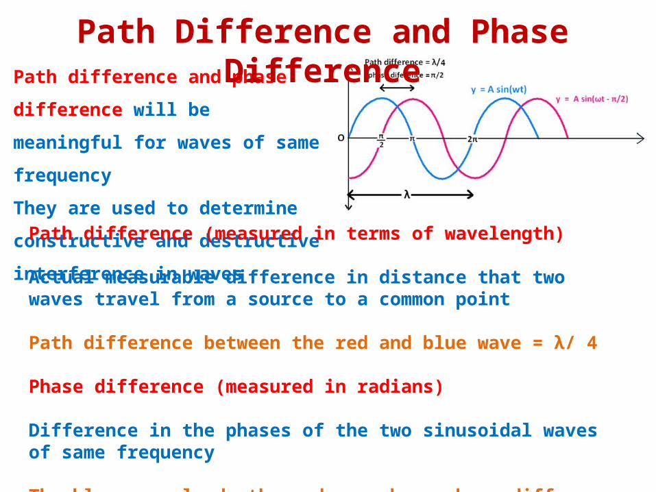
Path Difference and Phase Difference
Path difference (measured in terms of wavelength)
Actual measurable difference in distance that two waves travel from a source to a common point
Path difference between the red and blue wave = λ/ 4
Phase difference (measured in radians)
Difference in the phases of the two sinusoidal waves of same frequency
The blue wave leads the red wave by a phase difference of π/2 (90 degrees)
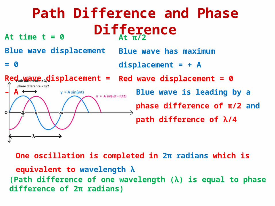
At time t = 0
Blue wave displacement = 0
Red wave displacement = – A
Path Difference and Phase Difference
At π/2
Blue wave has maximum displacement = + A
Red wave displacement = 0
Blue wave is leading by a phase difference
of π/2 and path difference of λ/4
One oscillation is completed in 2π radians which is equivalent to wavelength λ
(Path difference of one wavelength (λ) is equal to phase difference of 2π radians)
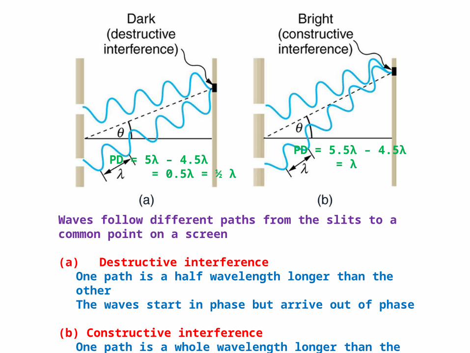
Waves follow different paths from the slits to a common point on a screen
(a) Destructive interference One path is a half wavelength longer than the otherThe waves start in phase but arrive out of phase
(b) Constructive interferenceOne path is a whole wavelength longer than the otherThe waves start out and arrive in phase
PD = 5λ – 4.5λ = 0.5λ = ½ λ
PD = 5.5λ – 4.5λ = λ
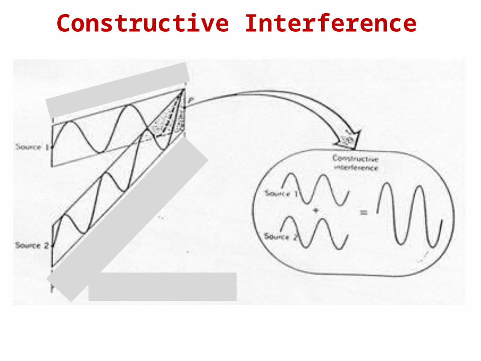
Constructive Interference
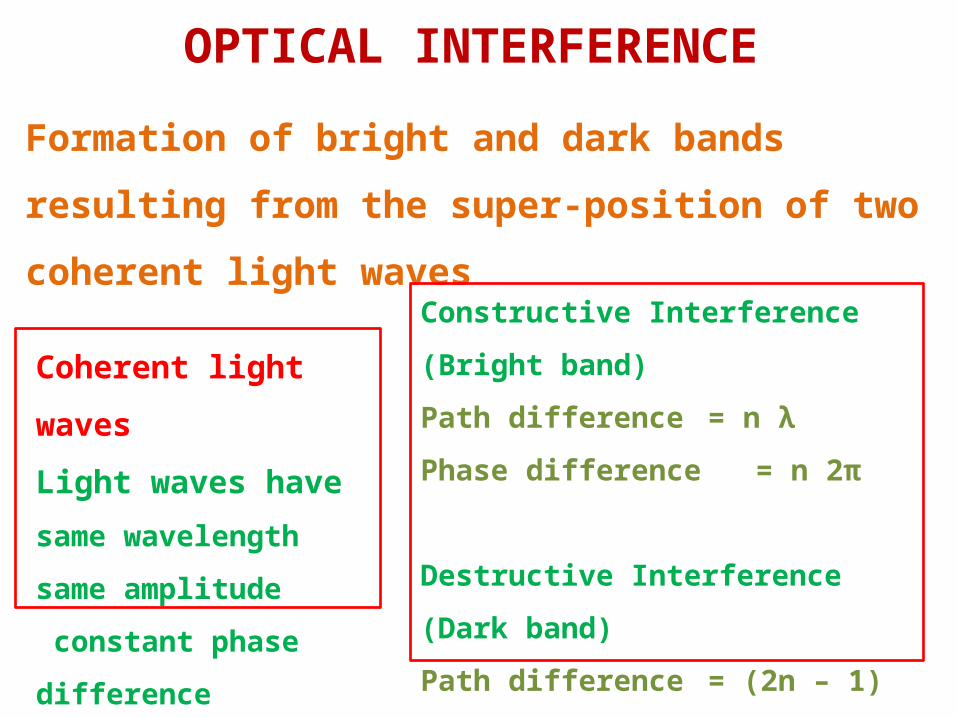
OPTICAL INTERFERENCE
Formation of bright and dark bands resulting from the
super-position of two coherent light waves
Coherent light waves
Light waves have
same wavelength
same amplitude
constant phase difference
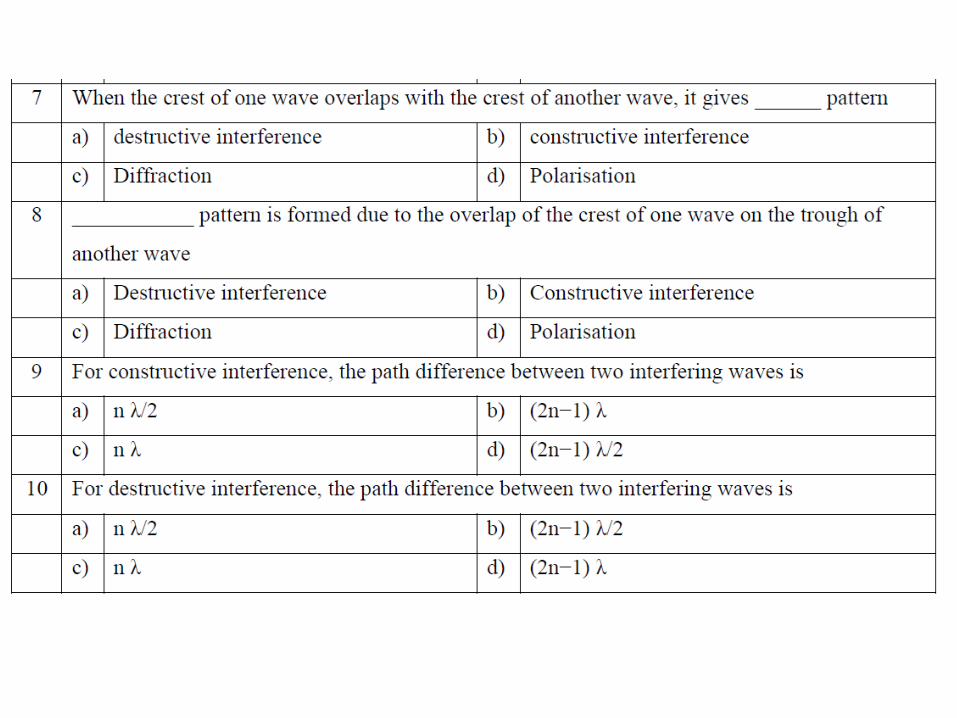
Constructive Interference (Bright band)
Path difference = n λ
Phase difference = n 2π
Destructive Interference (Dark band)
Path difference = (2n – 1) λ/2
Phase difference = (2n – 1)π
Optical Interference
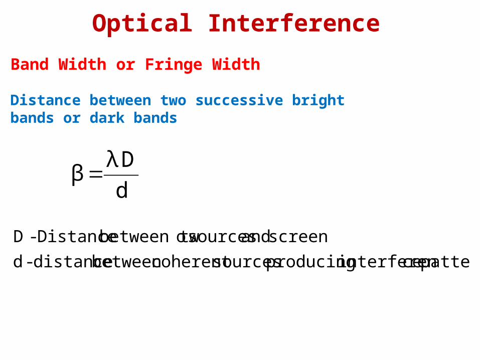
Band Width or Fringe Width
Distance between two successive bright bands or dark bands
d
D λ β
pattern ceinterferen producing sourcescoherent between distance - d
screen and sources obetween tw Distance - D
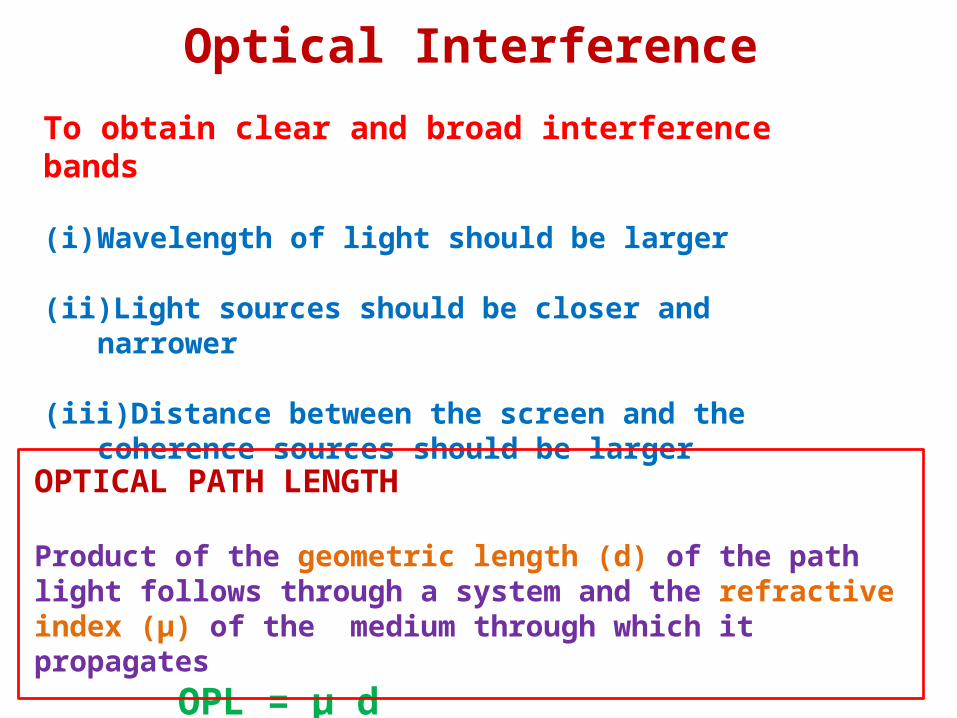
Optical Interference
To obtain clear and broad interference bands
(i) Wavelength of light should be larger
(ii) Light sources should be closer and narrower
(iii) Distance between the screen and the coherence sources should be larger
OPTICAL PATH LENGTH
Product of the geometric length (d) of the path light follows through a system and the refractive index (μ) of the medium through which it propagates
OPL = μ d
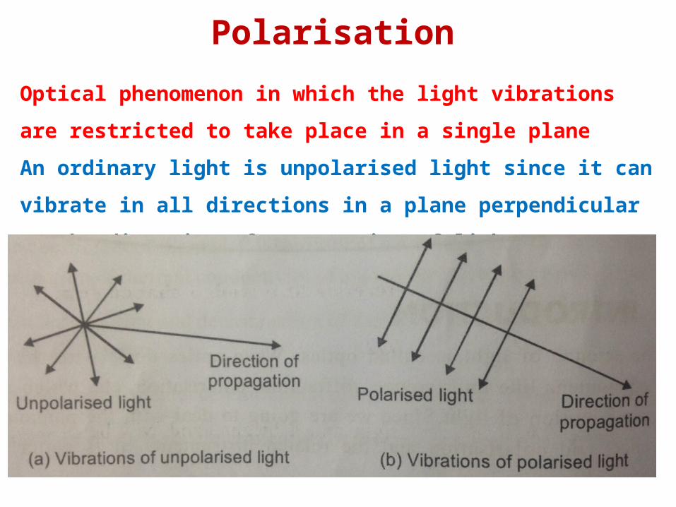
Polarisation
Optical phenomenon in which the light vibrations are restricted to take
place in a single plane
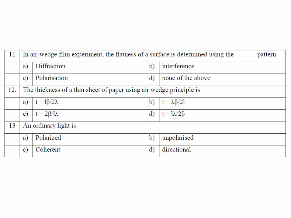
An ordinary light is unpolarised light since it can vibrate in all directions in
a plane perpendicular to the direction of propagation of light
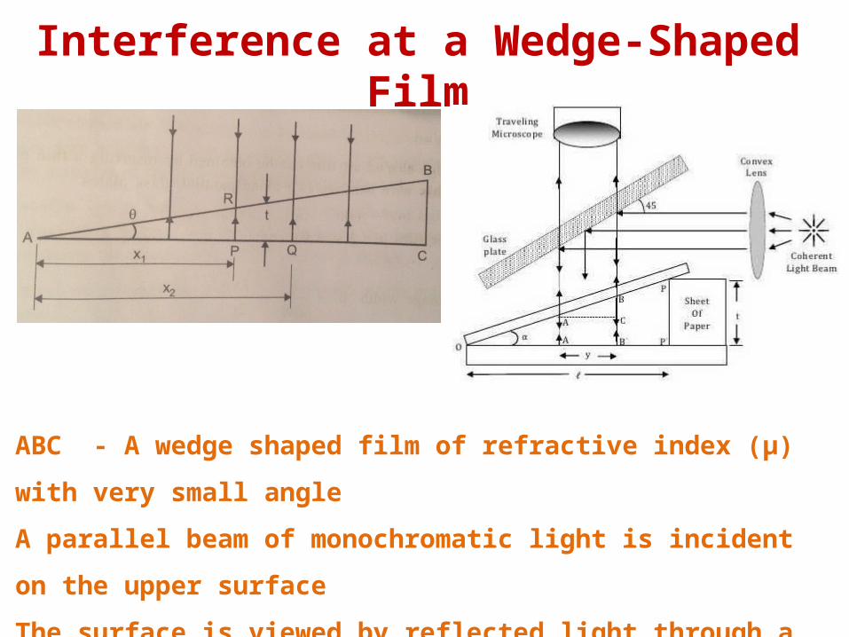
Interference at a Wedge-Shaped Film
ABC - A wedge shaped film of refractive index (μ) with very small angle
A parallel beam of monochromatic light is incident on the upper surface
The surface is viewed by reflected light through a travelling microscope
Alternate dark and bright bands can be observed
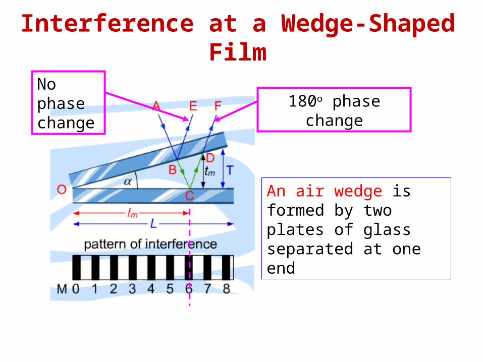
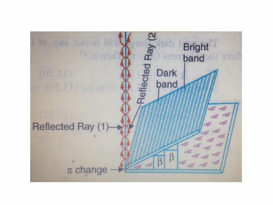
Interference at a Wedge-Shaped Film
An air wedge is formed by two plates of glass separated at one end
No phase change
180o phase change
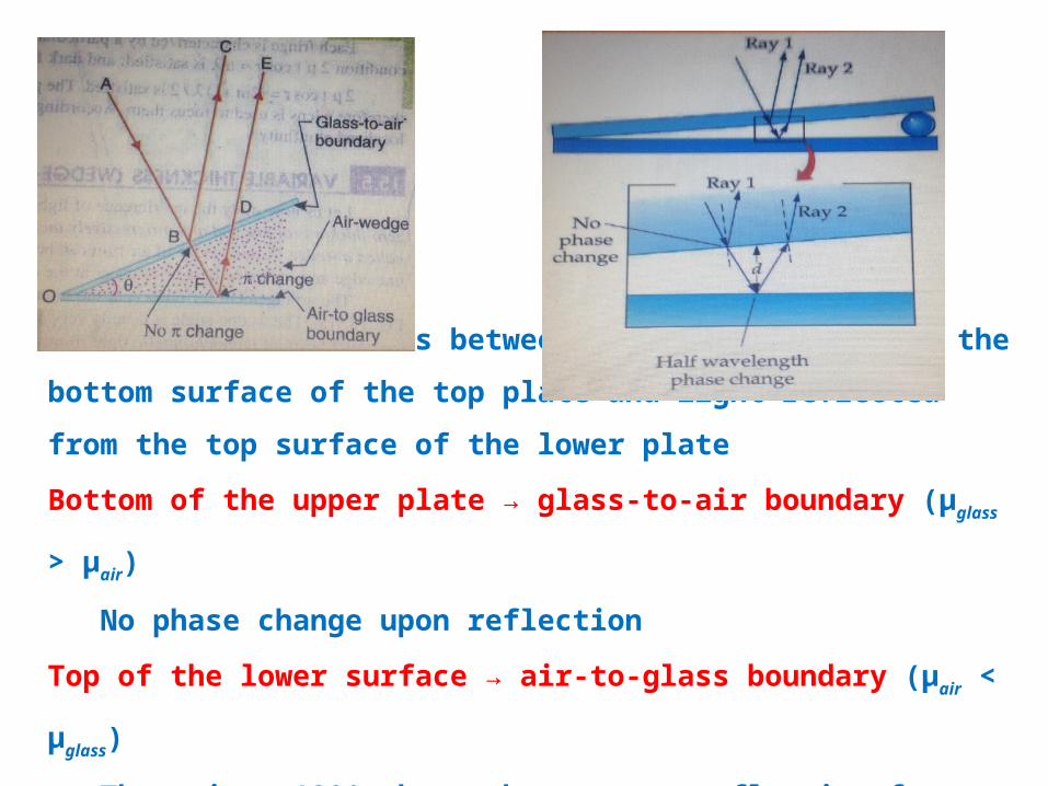
Interference effect is between light reflected from the bottom surface of the top
plate and light reflected from the top surface of the lower plate
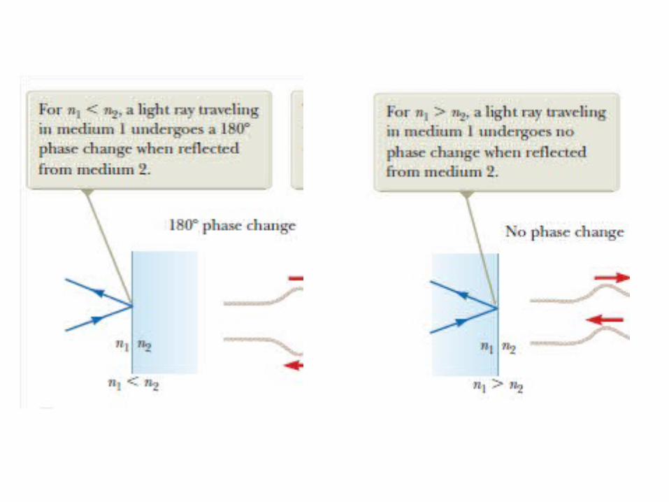
Bottom of the upper plate → glass-to-air boundary (μglass > μair)
No phase change upon reflection
Top of the lower surface → air-to-glass boundary (μair < μglass)
There is a 180° phase change upon reflection from this surface
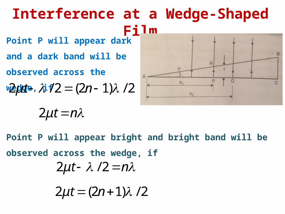
Interference at a Wedge-Shaped Film
Point P will appear dark and a dark
band will be observed across the
wedge, if
2/)12(2/2 nμt
nμt 2
Point P will appear bright and bright band will be observed across the
wedge, if
nμt 2/2
2/)12(2 nμt
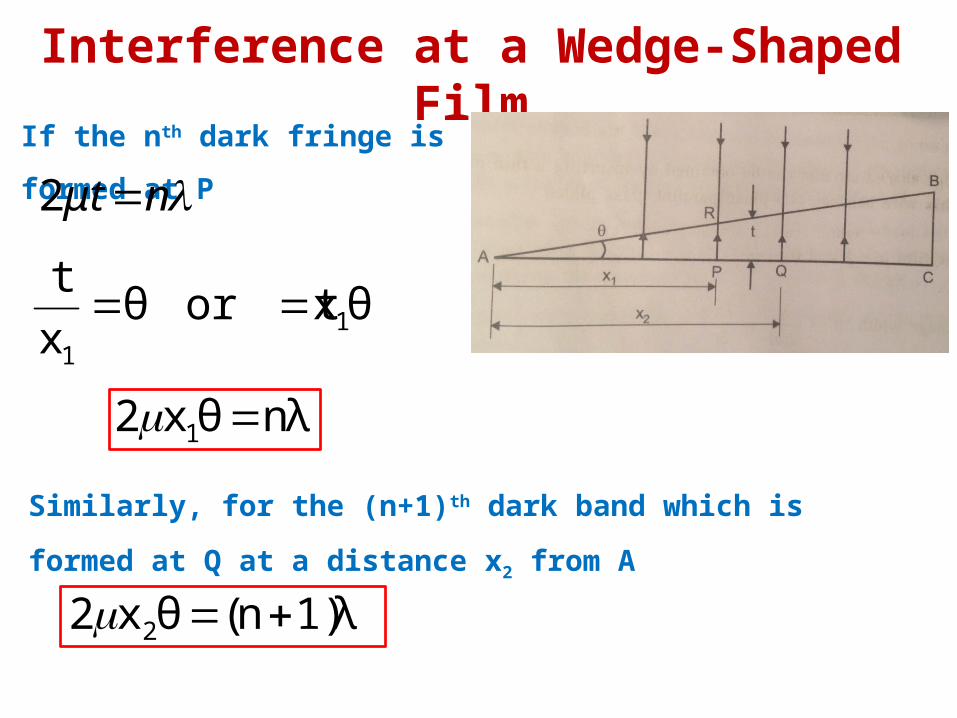
Interference at a Wedge-Shaped Film
If the nth dark fringe is formed at P
nμt 2
θxor t θx
t1
1
nλθx2 1
Similarly, for the (n+1)th dark band which is formed at Q at a distance
x2 from A
1)λn(θx2 2
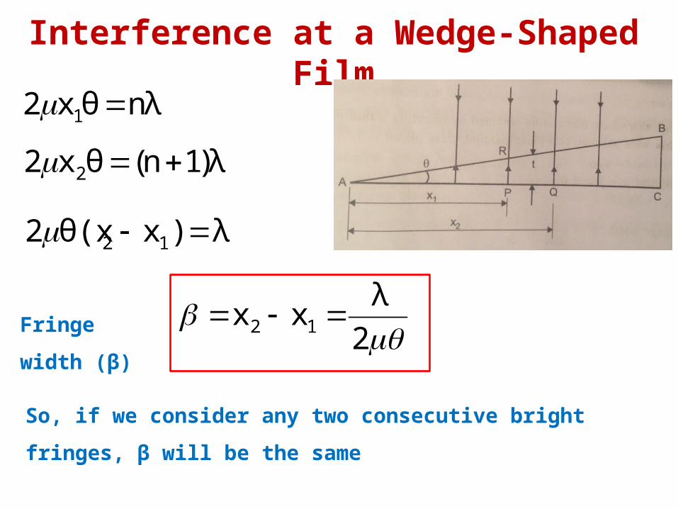
Interference at a Wedge-Shaped Film
So, if we consider any two consecutive bright fringes, β will be the same
nλθx2 1
Fringe width (β)
)λ1n(θx2 2
λ)xθ(x2 12
2
λxx 12
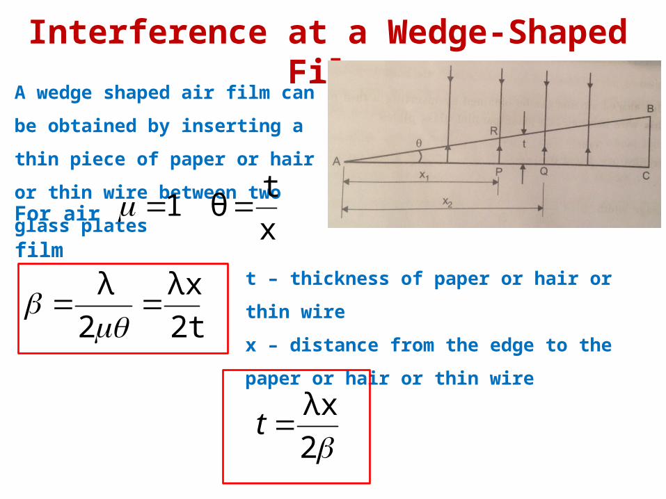
Interference at a Wedge-Shaped Film
A wedge shaped air film can be obtained
by inserting a thin piece of paper or hair
or thin wire between two glass plates
1For air film x
tθ
2t
λx
2
λ
t – thickness of paper or hair or thin wire
x – distance from the edge to the paper or hair or
thin wire
2
λxt
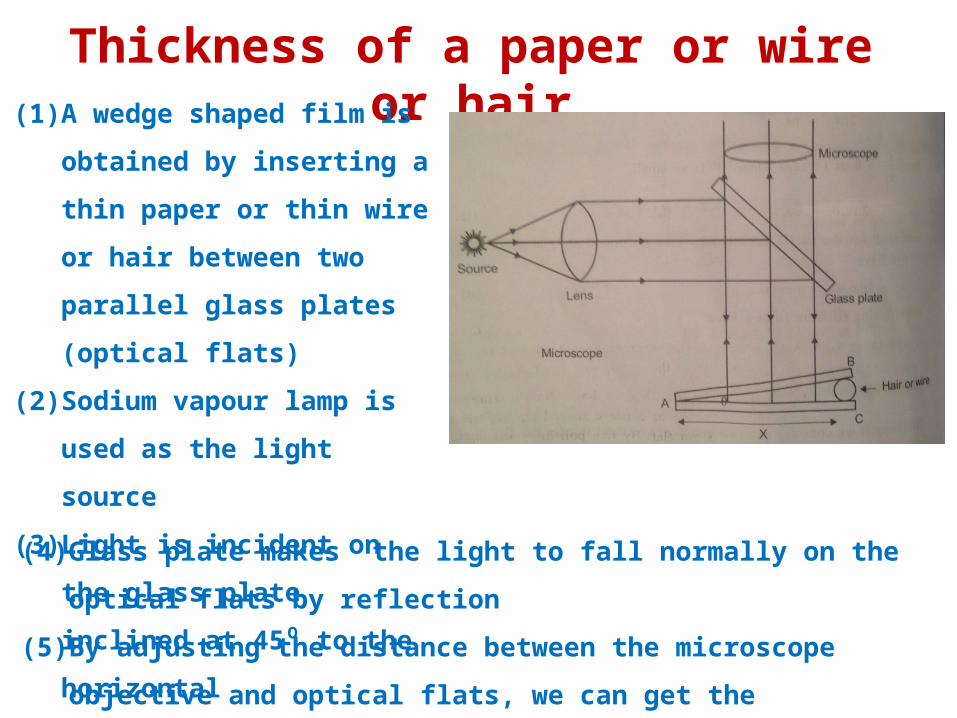
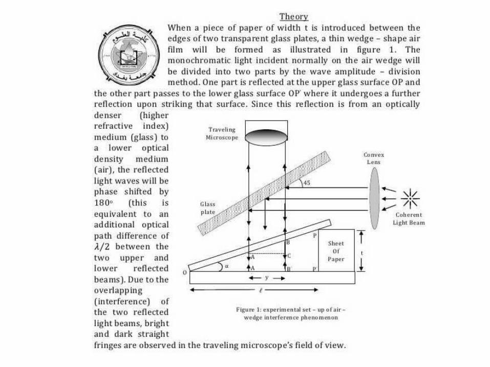
Thickness of a paper or wire or hair(1) A wedge shaped film is obtained
by inserting a thin paper or thin
wire or hair between two parallel
glass plates (optical flats)
(2) Sodium vapour lamp is used as
the light source
(3) Light is incident on the glass plate
inclined at 45⁰ to the horizontal
(4) Glass plate makes the light to fall normally on the optical flats by reflection
(5) By adjusting the distance between the microscope objective and optical flats,
we can get the interference fringes in the microscope eye piece
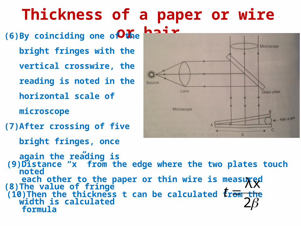
Thickness of a paper or wire or hair(6) By coinciding one of the bright
fringes with the vertical crosswire,
the reading is noted in the
horizontal scale of microscope
(7) After crossing of five bright fringes,
once again the reading is noted
(8) The value of fringe width is
calculated
(9) Distance “x” from the edge where the two plates touch each other to the
paper or thin wire is measured
(10) Then the thickness t can be calculated from the formula2
λxt
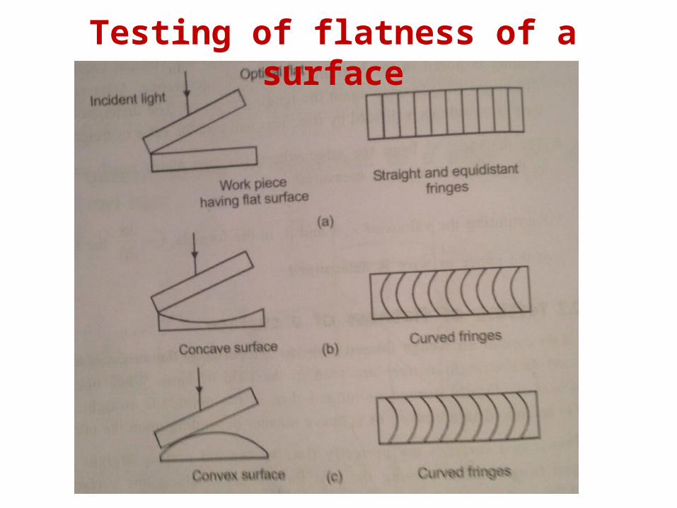
Testing of flatness of a surface
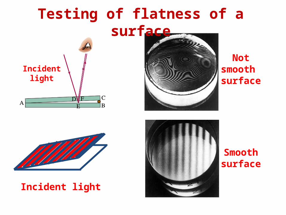
Not smooth surface
Smooth surface
Incident light
Incident light
Testing of flatness of a surface
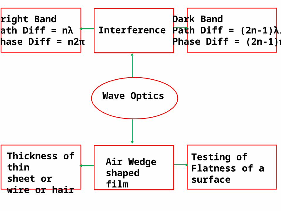
Wave Optics
InterferenceBright BandPath Diff = nλPhase Diff = n2π
Dark BandPath Diff = (2n-1)λ/2Phase Diff = (2n-1)π
Air Wedge shaped film
Thickness of thin sheet or wire or hair
Testing of Flatness of a surface