Embed Size (px)
Citation preview
745
Wave OpticsCHAPTER OUTLINE 27.1 Conditions for
Interference 27.2 Young’s Double-Slit
Experiment 27.3 Light Waves in
Interference 27.4 Change of Phase Due to
Reflection 27.5 Interference in Thin Films 27.6 Diffraction Patterns 27.7 Resolution of Single-Slit
and Circular Apertures 27.8 The Diffraction Grating 27.9 Diffraction of X-Rays by
Crystals 27.10 Context
ConnectionHolography
ANSWERS TO QUESTIONS Q27.1 (a) Two waves interfere constructively if their path difference is
zero, or an integral multiple of the wavelength, according to δ λ= m , with m = 0 1 2 3, , , , K.
(b) Two waves interfere destructively if their path difference is a
half wavelength, or an odd multiple of λ2
, described by
δ λ= +FHGIKJm
12
, with m = 0 1 2 3, , , , K.
Q27.2 The light from the flashlights consists of many different wavelengths (that’s why it’s white) with
random time differences between the light waves. There is no coherence between the two sources. The light from the two flashlights does not maintain a constant phase relationship over time. These three equivalent statements mean no possibility of an interference pattern.
Q27.3 Every color produces its own pattern, with a spacing between the maxima that is characteristic of the
wavelength. With several colors, the patterns are superimposed and it can be difficult to pick out a single maximum. Using monochromatic light can eliminate this problem.
Q27.4 Underwater, the wavelength of the light would decrease, λ λwater
air
water=
n. Since the positions of light
and dark bands are proportional to λ, (according to Equations 27.2 and 27.3), the underwater fringe separations will decrease.
Q27.5 The threads that are woven together to make the cloth have small meshes between them. These bits
of space act as pinholes through which the light diffracts. Since the cloth is a grid of such pinholes, an interference pattern is formed, as when you look through a diffraction grating.
Q27.6 If the oil film is brightest where it is thinnest, then n n nair oil water< < . With this condition, light
reflecting from both the top and the bottom surface of the oil film will undergo phase reversal. Then these two beams will be in phase with each other where the film is very thin. This is the condition for constructive interference as the thickness of the oil film decreases toward zero.
746 Wave Optics
Q27.7 As water evaporates from the ‘soap’ bubble, the thickness of the bubble wall approaches zero. Since light reflecting from the front of the water surface is phase-shifted 180° and light reflecting from the back of the soap film is phase-shifted 0°, the reflected light meets the conditions for a minimum. Thus the soap film appears black, as in the illustration accompanying textbook Example 27.4, “Interference in a Wedge-Shaped Film.”
Q27.8 If the film is more than a few wavelengths thick, the interference fringes are so close together that
you cannot resolve them. Q27.9 Suppose the coating is intermediate in index of refraction between vacuum and the glass. When the
coating is very thin, light reflected from its top and bottom surfaces will interfere constructively, so you see the surface white and brighter. As the thickness reaches one quarter of the wavelength of violet light in the coating, destructive interference for violet will make the surface look red or perhaps orange. Next to interfere destructively are blue, green, yellow, orange, and red, making the surface look red, purple, and then blue. As the coating gets still thicker, we can get constructive interference for violet and then for other colors in spectral order. Still thicker coating will give constructive and destructive interference for several visible wavelengths, so the reflected light will start to look white again.
Q27.10 The wavelength of light is extremely small in comparison to the dimensions of your hand, so the
diffraction of light around an obstacle the size of your hand is totally negligible. However, sound waves have wavelengths that are comparable to the dimensions of the hand or even larger. Therefore, significant diffraction of sound waves occurs around hand-sized obstacles.
Q27.11 Audible sound has wavelengths on the order of meters or centimeters, while visible light has a
wavelength on the order of half a micrometer. In this world of breadbox-sized objects, λa
is large for
sound. When sound goes through a doorway, the sound diffracts around behind the adjoining
walls. But λa
is a tiny fraction for visible light passing ordinary-size objects or apertures, so light
changes its direction by only very small angles when it diffracts. Another way of phrasing the answer: We can see by a small angle around a small obstacle or
around the edge of a small opening. The side fringes in Figure 27.12 and the Arago spot in the center of Figure 27.13 show this diffraction. We cannot always hear around corners. Out-of-doors, away from reflecting surfaces, have someone a few meters distant face away from you and whisper. The high-frequency, short-wavelength, information-carrying components of the sound do not diffract around his head enough for you to understand his words.
Q27.12 Yes, but no diffraction effects are observed because the separation distance between adjacent ribs is
so much greater than the wavelength of x-rays. Diffraction does not limit the resolution of an x-ray image. Diffraction might sometimes limit the resolution of an ultrasonogram.
Q27.13 The intensity of the light coming through the slit decreases, as you would expect. The central
maximum increases in width as the width of the slit decreases. In the condition sinθ λ=a
for
destructive interference on each side of the central maximum, θ increases as a decreases.
Chapter 27 747
Q27.14 It is shown in the correct orientation. If the horizontal width of the opening is equal to or less than the wavelength of the sound, then the equation a sinθ λ= 1a f has the solution θ = °90 , or has no solution. The central diffraction maximum covers the whole seaward side. If the vertical height of the opening is large compared to the wavelength, then the angle in a sinθ λ= 1a f will be small, and the central diffraction maximum will form a thin horizontal sheet.
Q27.15 The fine hair blocks off light that would otherwise go through a fine slit and produce a diffraction
pattern on a distant screen. The width of the central maximum in the pattern is inversely proportional to the distance across the slit. When the hair is in place, it subtracts the same diffraction pattern from the projected disk of laser light. The hair produces a diffraction minimum that crosses the bright circle on the screen. The width of the minimum is inversely proportional to the diameter of the hair. The central minimum is flanked by narrower maxima and minima. Measure the width 2y of the central minimum between the maxima bracketing it, and use Equation 27.13 in the form yL a
= λ to find the width a of the hair.
Q27.16 The condition for constructive interference is that the three radio signals arrive at the city in phase.
We know the speed of the waves (it is the speed of light c), the angular bearing θ of the city east of north from the broadcast site, and the distance d between adjacent towers. The wave from the westernmost tower must travel an extra distance 2d sinθ to reach the city, compared to the signal from the eastern tower. For each cycle of the carrier wave, the western antenna would transmit first,
the center antenna after a time delay d
csinθ
, and the eastern antenna after an additional equal time
delay.
SOLUTIONS TO PROBLEMS Section 27.1 Conditions for Interference Section 27.2 Young’s Double-Slit Experiment Section 27.3 Light Waves in Interference
P27.1 yL
dmbright =
λ
For m = 1 , λ = =× ×
=− −
ydL
3 40 10 5 00 10
3 30515
3 4. .
.
m m
m nm
e je j
P27.2 λ = = =−vf
3542 000
0 1771 m s
s m.
(a) d msinθ λ= so 0 300 1 0 177. sin . m ma f a fθ = and θ = °36 2.
(b) d msinθ λ= so d sin . .36 2 1 0 030 0° = mb g and d = 5 08. cm
continued on next page
748 Wave Optics
(c) 1 00 10 36 2 16. sin .× ° =− me j a fλ so λ = 590 nm
fc= =
××
=−λ3 00 105 90 10
5088
7..
m s m
THz
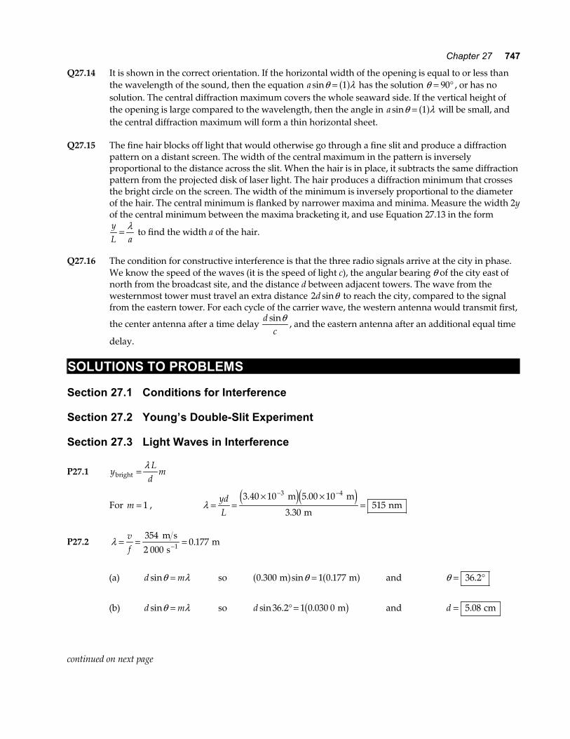
P27.3 Note, with the conditions given, the small angle approximation does not
work well. That is, sinθ , tanθ , and θ are significantly different. We treat the interference as a Fraunhofer pattern.
(a) At the m = 2 maximum, tan .θ = =4000 400
m1 000 m
θ = °21 8.
so λ θ= =°
=dmsin sin .
.300 21 8
255 7
m m
a f.
(b) The next minimum encountered is the m = 2 minimum;
1 000 m
400 m
300 m
FIG. P27.3
and at that point, d msinθ λ= +FHGIKJ
12
which becomes d sinθ λ= 52
or sin.
.θ λ= 5 = FHGIKJ =2
52
55 70 464
d m
300 m
and θ = °27 7.
so y = ° =1 000 27 7 524 m mb gtan . .
Therefore, the car must travel an additional 124 m .
If we considered Fresnel interference, we would more precisely find
(a) λ = + − +FH IK =12
550 1 000 250 1 000 55 22 2 2 2 . m and (b) 123 m.
P27.4 λ = =3402 000
0 170 m s
Hz m.
Maxima are at d msinθ λ= :
m = 0 gives θ = °0
m = 1 gives sin.θ λ= =
d0 170 m0.350 m
θ = °29 1.
m = 2 gives sin .θ λ= =20 971
d θ = °76 3.
m = 3 gives sin .θ = 1 46 No solution. continued on next page
Chapter 27 749
Minima are at d msinθ λ= +FHGIKJ
12
:
m = 0 gives sin .θ λ= =2
0 243d
θ = °14 1.
m = 1 gives sin .θ λ= =32
0 729d
θ = °46 8.
m = 2 gives sin .θ = 1 21 No solution.
So we have maxima at 0 , 29.1 , and 76.3 ; minima at 14.1 and 46.8° ° ° ° ° .
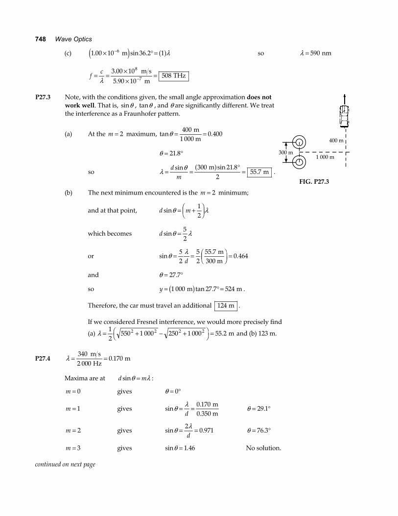
P27.5 In the equation d msinθ λ= +FHGIKJ
12
.
The first minimum is described by m = 0
and the tenth by m = 9 : sinθ λ= +FHGIKJd
912
.
Also, tanθ =yL
but for small θ, sin tanθ θ≈ .
Thus, dL
y= =9 5 9 5.
sin.λ
θλ
d =×
×= × =
−
−−
9 5 5 890 10 2 00
7 26 101 54 10 1 54
10
33
. .
.. .
m m
m m mm
e ja f.
L
dSource
y
FIG. P27.5
*P27.6 Location of A = central maximum,
Location of B = first minimum.
So, ∆y y yL
dL
d= − = +FHG
IKJ − = =min max .
λ λ0
12
012
20 0 m .
Thus, dL= = =λ
2 20 03 00 150
40 011 3
..
..
m m m
m ma f
a fa f.
P27.7 At 30 0. ° , d msinθ λ=
3 20 10 30 0 500 104 9. sin .× ° = ×− − m me j e jm so m = 320
There are 320 maxima to the right, 320 to the left, and one for m = 0 straight ahead.
There are 641 maxima .
750 Wave Optics
P27.8 Observe that the pilot must not only home in on the airport, but must be headed in the right direction when she arrives at the end of the runway.
(a) λ = =××
=−cf
3 1030 10
10 08
6 1 m s s
m.
(b) The first side maximum is at an angle given by d sinθ λ= 1a f .
40 10 m ma fsinθ = θ = °14 5. tanθ =yL
y L= = ° =tan tan .θ 2 000 14 5 516 m mb g
(c) The signal of 10-m wavelength in parts (a) and (b) would show maxima at 0°, 14.5°, 30.0°,
48.6°, and 90°. A signal of wavelength 11.23-m would show maxima at 0°, 16.3°, 34.2°, and 57.3°. The only value in common is 0°. If λ1 and λ 2 were related by a ratio of small integers
(a just musical consonance!) in λλ
1
2
1
2=
nn
, then the equations d nsinθ λ= 2 1 and d nsinθ λ= 1 2
would both be satisfied for the same nonzero angle. The pilot could come flying in with that inappropriate bearing, and run off the runway immediately after touchdown.
P27.9 φ πλ
θ πλ
= = FHGIKJ
2 2d d
yL
sin
(a) φ π=×
× ° =−
−2
5 00 101 20 10 0 500 13 2
74
.. sin . .
m m rad
e j e j a f
(b) φ π=×
× ×FHG
IKJ =−
−−2
5 00 101 20 10
5 00 106 28
74
3
..
..
m m
m1.20 m
rade j e j
(c) If φ π θλ
= =0 3332
.sin
radd
θλ φπ π
=FHGIKJ =
×
×
L
NMM
O
QPP
− −−
−sin sin
. .
.1 1
7
42
5 00 10 0 333
2 1 20 10d
m rad
m
e ja fe j
θ = × −1 27 10 2. deg .
(d) If d sinθ λ=4
θ λ= FHGIKJ =
××
L
NMM
O
QPP
− −−
−sin sin
.1 1
7
445 10
4 1 20 10d m
me j
θ = × −5 97 10 2. deg .
*P27.10 The path difference between rays 1 and 2 is: δ θ θ= −d dsin sin1 2 .
For constructive interference, this path difference must be equal to an integral number of wavelengths: d d msin sinθ θ λ1 2− = , or
d msin sinθ θ λ1 2− =b g .
Chapter 27 751
P27.11 I Id
av = FHG
IKJmax cos
sin2 π θλ
For small θ, sinθ ≈yL
and I Iav = 0 750. max
yLd
II
yI
I
av=
=×
×=
−
−
−−
λπ
πµ
cos
. .
.cos
..
max
max
max
1
7
31
6 00 10 1 20
2 50 10
0 75048 0
e ja fe j
m
m m
P27.12 (a) The intensity of the sum of two coherent waves is described by I
Imaxcos= FHGIKJ
2
2φ
. Therefore,
φ = = =− −2 2 0 640 1 291 1cos cos . .max
II
rad .
(b) δλ φ
π π= = =
2486 1 1 29
299 6
. ..
nm rad nm
a fa f
P27.13 I IydL
=FHGIKJmax cos2 π
λ
I
Imaxcos
. .
. ..=
× ×
×
L
NMM
O
QPP =
− −
−2
3 4
9
6 00 10 1 80 10
656 3 10 0 8000 968
π m m
m m
e je je ja f
Section 27.4 Change of Phase Due to Reflection Section 27.5 Interference in Thin Films P27.14 Light reflecting from the first surface suffers phase reversal. Light reflecting from the second surface
does not, but passes twice through the thickness t of the film. So, for constructive interference, we require
λ λn
nt2
2+ =
where λ λn n
= is the wavelength in the material.
Then 22 2
tn
n= =λ λ
λ = = =4 4 1 33 115 612nt .a fa f nm nm .
752 Wave Optics
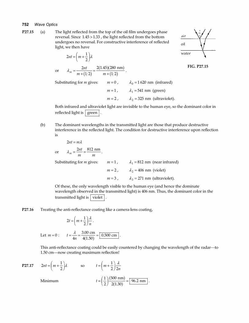
P27.15 (a) The light reflected from the top of the oil film undergoes phase reversal. Since 1 45 1 33. .> , the light reflected from the bottom undergoes no reversal. For constructive interference of reflected light, we then have
212
nt m= +FHGIKJλ
or λ mnt
m m=
+=
+2
1 22 1 45 280
1 2b ga fa fb g
. nm.
FIG. P27.15
Substituting for m gives: m = 0 , λ 0 1 620= nm (infrared)
m = 1 , λ1 541= nm (green)
m = 2 , λ 2 325= nm (ultraviolet).
Both infrared and ultraviolet light are invisible to the human eye, so the dominant color in reflected light is green .
(b) The dominant wavelengths in the transmitted light are those that produce destructive
interference in the reflected light. The condition for destructive interference upon reflection is
2nt m= λ
or λ mntm m
= =2 812 nm.
Substituting for m gives: m = 1 , λ1 812= nm (near infrared)
m = 2 , λ 2 406= nm (violet)
m = 3 , λ 3 271= nm (ultraviolet).
Of these, the only wavelength visible to the human eye (and hence the dominate wavelength observed in the transmitted light) is 406 nm. Thus, the dominant color in the transmitted light is violet .
P27.16 Treating the anti-reflectance coating like a camera-lens coating,
212
t mn
= +FHGIKJ
λ.
Let m = 0 : tn
= = =λ4
3 000 500
..
cm4 1.50
cma f .
This anti-reflectance coating could be easily countered by changing the wavelength of the radar—to 1.50 cm—now creating maximum reflection!
P27.17 212
nt m= +FHGIKJλ so t m
n= +FHG
IKJ
12 2
λ
Minimum t = FHGIKJ =1
25002 1 30
96 2 nm
nma fa f.
. .
Chapter 27 753
*P27.18 (a) For maximum transmission, we want destructive interference in the light reflected from the front and back surfaces of the film.
If the surrounding glass has refractive index greater than 1.378, light reflected from the front surface suffers no phase reversal and light reflected from the back does undergo phase reversal. This effect by itself would produce destructive interference, so we want the
distance down and back to be one whole wavelength in the film: 2tn
= λ.
tn
= = =λ2
656 3238
. nm2 1.378
nma f
(b) The filter will expand. As t increases in 2nt = λ , so does λ increase .
(c) Destructive interference for reflected light happens also for λ in 2 2nt = λ ,
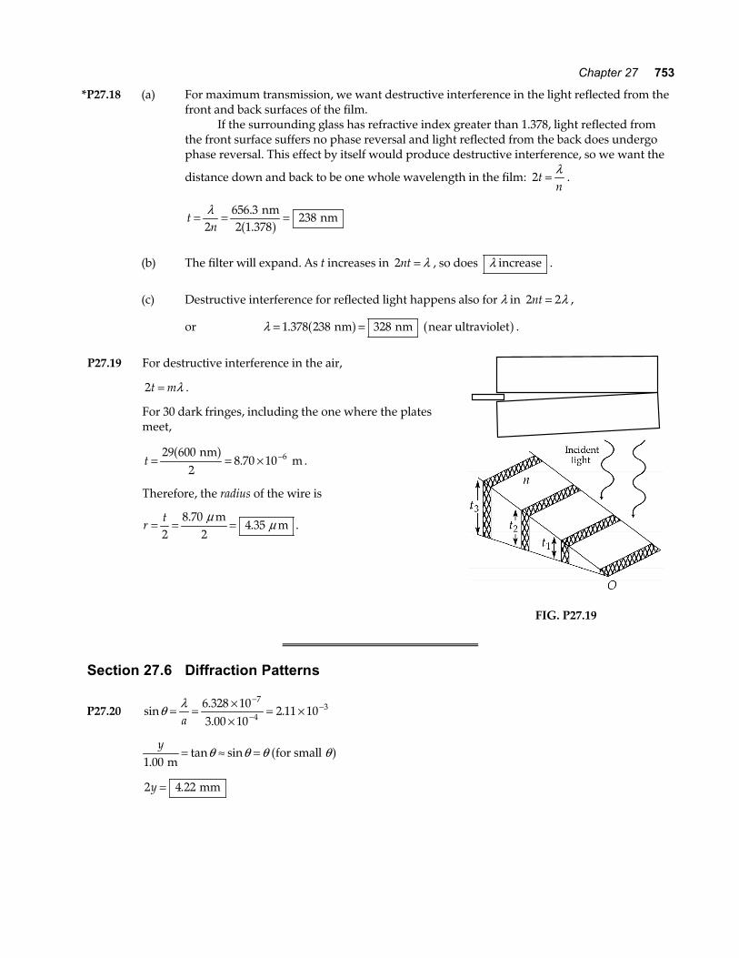
or λ = =1 378 238 328. nm nm near ultravioleta f a f . P27.19 For destructive interference in the air,
2t m= λ .
For 30 dark fringes, including the one where the plates meet,
t = = × −29 6002
8 70 10 6 nm m
a f. .
Therefore, the radius of the wire is
rt= = =2
8 704 35
..
m2
mµ µ .
FIG. P27.19
Section 27.6 Diffraction Patterns
P27.20 sin..
.θ λ= = ××
= ×−
−−
a6 328 103 00 10
2 11 107
43
y
1 00.tan sin
m for small = ≈ =θ θ θ θa f
2 4 22y = . mm
754 Wave Optics
P27.21 yL
ma
≈ =sinθ λ ∆y = × −3 00 10 3. nm
∆m = − =3 1 2 and am L
y=
∆∆
λ
a =×
×= ×
−
−−
2 690 10 0 500
3 00 102 30 10
9
34
m m
m m
e ja fe j
.
..
P27.22 The positions of the first-order minima are yL a
≈ = ±sinθ λ. Thus, the spacing between these two
minima is ∆ya
L= FHGIKJ2
λ and the wavelength is
λ = FHGIKJFHGIKJ =
×FHG
IKJ
×FHG
IKJ =
− −∆y aL2
4 10 10 0 550 10547
3 3. . m2
m2.06 m
nm .
P27.23 For destructive interference,
sin.
.θ λ λ= = = =ma a
5 000 139
cm36.0 cm
and θ = °7 98.
dL
= tanθ
gives d L= = ° =tan . tan . .θ 6 50 7 98 0 912 m ma f
d = 91 2. cm .
P27.24 If the speed of sound is 340 m/s, λ = = =−vf
340650
0 5231
m s s
m. .
Diffraction minima occur at angles described by a msinθ λ=
1 10 1 0 5231. sin . m ma f a fθ = θ 1 28 4= °.
1 10 2 0 5232. sin . m ma f a fθ = θ 2 72 0= °.
1 10 3 0 5233. sin . m ma f a fθ = θ 3 nonexistent
Maxima appear straight ahead at 0° and left and right at an angle given approximately by
1 10 1 5 0 523. sin . . m ma f a fθ x = θ x ≈ °46 .
There is no solution to a sin .θ λ= 2 5 , so our answer is already complete, with three sound
maxima.
Chapter 27 755
*P27.25 The rectangular patch on the wall is wider than it is tall. The aperture will be taller than it is wide. For horizontal spreading we have
tan.
..
sin
..
θ
θ λ
widthwidth
width width
width
m 2 m
m0.012 2
m
= = =
=
= × = ×−
−
yL
a
a
0 1104 5
0 012 2
1
632 8 105 18 10
95
For vertical spreading, similarly
tan
..
.
sin.
.
θ
λθ
height
height
m 2 m
m0.000 667
m
= =
= = × = ×−
−
0 0064 5
0 000 667
1 632 8 109 49 10
94a
h
Section 27.7 Resolution of Single-Slit and Circular Apertures
P27.26 sin.
.θ λ= = ××
= ×−
−−
a5 00 10
1 00 107
43 m
5.00 10 rad
P27.27 Undergoing diffraction from a circular opening, the beam spreads into a cone of half-angle
θ λmin . .
..= = ×F
HGIKJ = ×
−−1 22 1 22
632 8 101 54 10
94
D m
0.005 00 m rad .
The radius of the beam ten kilometers away is, from the definition of radian measure,
rbeam m m= × =θ min . .1 00 10 1 5444e j
and its diameter is d rbeam beam m= =2 3 09. .
*P27.28 By Rayleigh’s criterion: θ λmin .= =d
L D1 22 , where θ min is the smallest angular separation of two
objects for which they are resolved by an aperture of diameter D, d is the separation of the two objects, and L is the maximum distance of the aperture from the two objects at which they can be resolved.
Two objects can be resolved if their angular separation is greater than θ min . Thus, θ min should be as small as possible. Therefore, the smaller of the two given wavelengths is easier to resolve, i.e.
violet .
LDd= =
× ×= ×
− − −
1 22
5 20 10 2 80 10
1 221 193 10
3 2 4
.
. .
..
λ λ λ
m m m2e je j
Thus L = 186 m for λ = 640 nm, and L = 271 m for λ = 440 nm. The viewer can resolve adjacent tubes of violet in the range 186 m to 271 m , but cannot resolve adjacent tubes of red in this range.
756 Wave Optics
P27.29 By Rayleigh’s criterion, two dots separated center-to-center by 2.00 mm would overlap
when θ λmin .= =d
L D1 22 .
Thus, LdD= =
× ×
×=
− −
−1 22
2 00 10 4 00 10
1 22 500 1013 1
3 3
9.
. .
..
λ m m
m m
e je je j
.
P27.30 The concave mirror of the spy satellite is probably about 2 m in diameter, and is surely not more
than 5 m in diameter. That is the size of the largest piece of glass successfully cast to a precise shape, for the mirror of the Hale telescope on Mount Palomar. If the spy satellite had a larger mirror, its manufacture could not be kept secret, and it would be visible from the ground. Outer space is probably closer than your state capitol, but the satellite is surely above 200-km altitude, for reasonably low air friction. We find the distance between barely resolvable objects at a distance of 200 km, seen in yellow light through a 5-m aperture:
yL D
y
=
= ×FHG
IKJ =
−
1 22
200 000 1 226 10
37
.
.
λ
m m
5 m cmb ga f
(Considering atmospheric seeing caused by variations in air density and temperature, the distance
between barely resolvable objects is more like 200 000 11
3 60097 m s
s rad
180 cmb ga f °F
HGIKJ °FHGIKJ =
π.) Thus the
snooping spy satellite cannot see the difference between III and II or IV on a license plate. It cannot count coins spilled on a sidewalk, much less read the date on them.
P27.31 1 22.λD
dL
= λ = =cf
0 020 0. m
D = 2 10. m L = 9 000 m
d = =1 220 020 0 9 000
2 10105.
.
.
m m
m m
b gb g
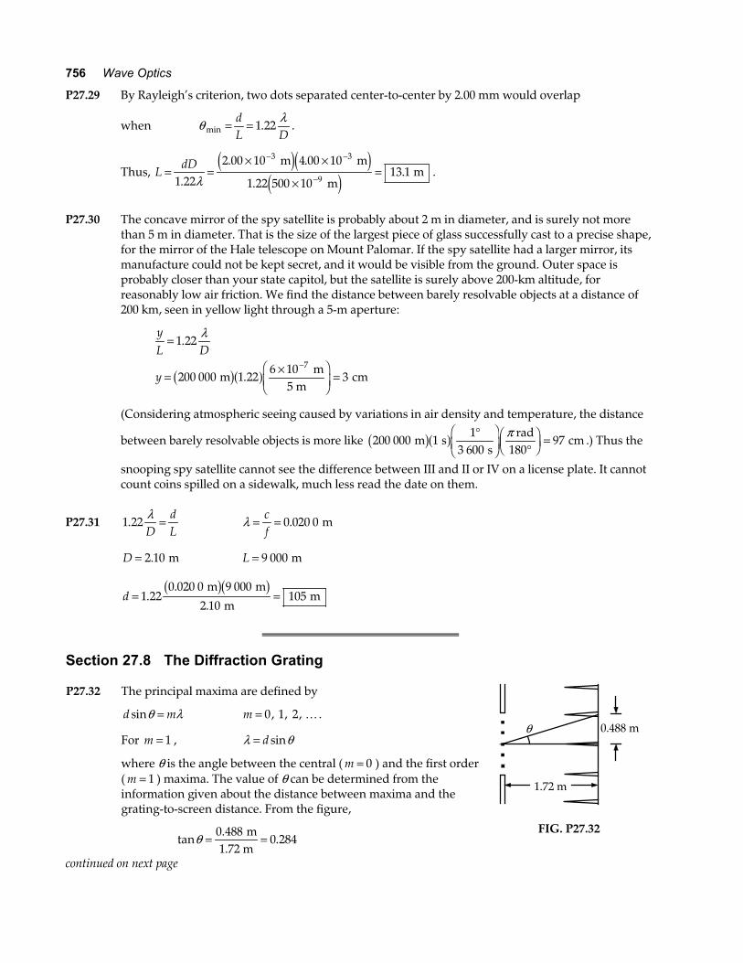
Section 27.8 The Diffraction Grating P27.32 The principal maxima are defined by
d msinθ λ= m = 0 1 2, , , K .
For m = 1 , λ θ= d sin
where θ is the angle between the central ( m = 0 ) and the first order ( m = 1 ) maxima. The value of θ can be determined from the information given about the distance between maxima and the grating-to-screen distance. From the figure,
tan.
.θ = =0 4880 284
m1.72 m
θ
1.72 m
0.488 m
FIG. P27.32
continued on next page
Chapter 27 757
so θ = °15 8.
and sin .θ = 0 273 .
The distance between grating “slits” equals the reciprocal of the number of grating lines per centimeter
d = = × = ×−−1
5 3101 88 10 1 88 101
4 3
cm cm nm. . .
The wavelength is λ θ= = × =d sin . .1 88 10 0 273 5143 nm nme ja f .
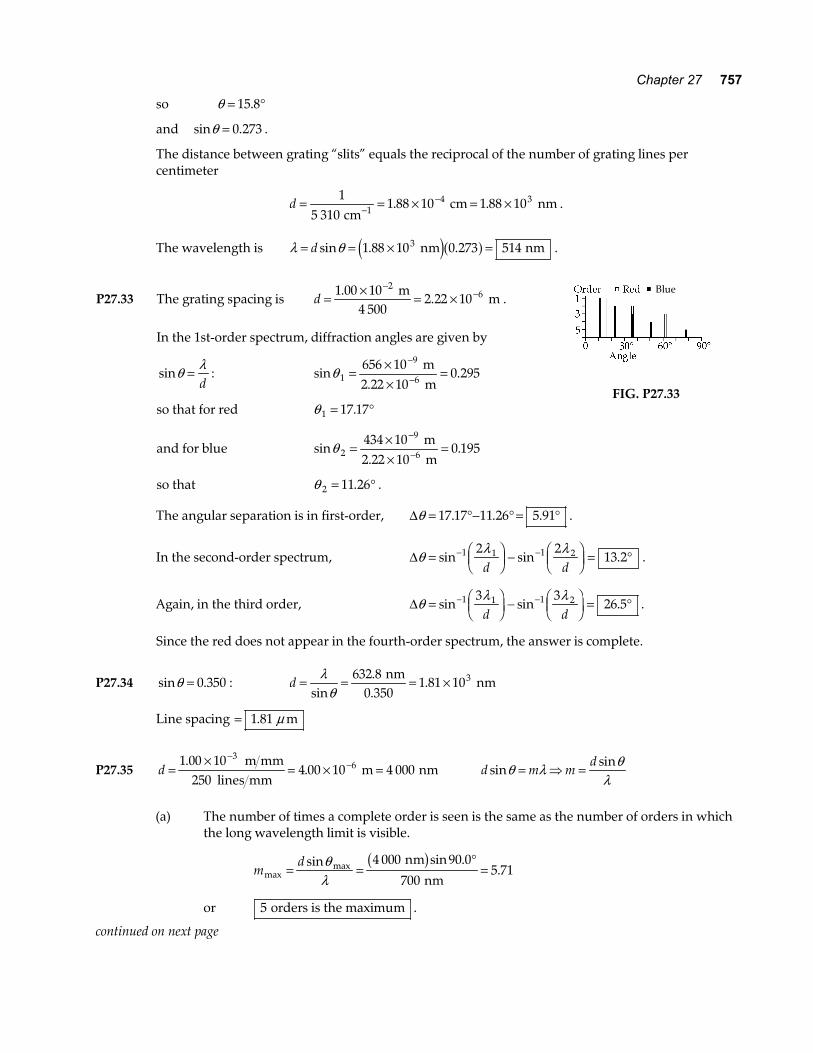
P27.33 The grating spacing is d = × = ×−
−1 00 102 22 10
26.
. m
4 500 m .
In the 1st-order spectrum, diffraction angles are given by
sinθ λ=d
: sin .θ 1
9
6656 10
0 295= ××
=−
− m
2.22 10 m
so that for red θ 1 17 17= °.
and for blue sin .θ 2
9
6434 10
100 195= ×
×=
−
− m
2.22 m
so that θ 2 11 26= °. .
Blue
FIG. P27.33
The angular separation is in first-order, ∆θ = °− ° = °17 17 11 26 5 91. . . .
In the second-order spectrum, ∆θ λ λ= FHGIKJ −
FHGIKJ = °− −sin sin .1 1 1 22 2
13 2d d
.
Again, in the third order, ∆θ λ λ= FHGIKJ −
FHGIKJ = °− −sin sin .1 1 1 23 3
26 5d d
.
Since the red does not appear in the fourth-order spectrum, the answer is complete.
P27.34 sin .θ = 0 350 : d = = = ×λθsin
..
632 81 81 103 nm
0.350 nm
Line spacing = 1 81. mµ
P27.35 d =×
= × =−
−1 00 10250
4 00 10 4 0003
6..
m mm lines mm
m nm d m md
sinsinθ λ θλ
= ⇒ =
(a) The number of times a complete order is seen is the same as the number of orders in which
the long wavelength limit is visible.
md
maxmaxsin sin .
.= =°
=θλ
4 000 90 0
7005 71
nm
nmb g
or 5 orders is the maximum .
continued on next page
758 Wave Optics
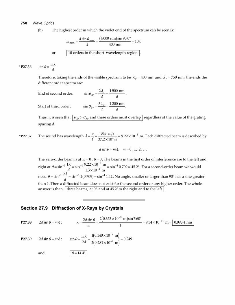
(b) The highest order in which the violet end of the spectrum can be seen is:
md
maxmaxsin sin .
.= =°
=θλ
4 000 90 0
40010 0
nm
nmb g
or 10 orders in the short-wavelength region .
*P27.36 sinθ λ= md
Therefore, taking the ends of the visible spectrum to be λ v = 400 nm and λ r = 750 nm , the ends the different order spectra are:
End of second order: sinθ λ2
2 1 500r
r
d d= =
nm.
Start of third order: sinθ λ3
3 1 200v
v
d d= =
nm.
Thus, it is seen that θ θ2 3r v> and these orders must overlap regardless of the value of the grating
spacing d.
*P27.37 The sound has wavelength λ = =×
= × −vf
34337 2 10
9 22 1033m s
s m
.. . Each diffracted beam is described by
d m msin , , , ,θ λ= = 0 1 2 K
The zero-order beam is at m = 0 , θ = 0. The beams in the first order of interference are to the left and
right at θ λ= = ××
= = °− −−
−−sin sin
..
sin . .1 13
211 9 22 10
1 3 100 709 45 2
d mm
. For a second-order beam we would
need θ λ= = =− − −sin sin . sin .1 1 122 0 709 1 42
da f . No angle, smaller or larger than 90° has a sine greater
than 1. Then a diffracted beam does not exist for the second order or any higher order. The whole answer is then, three beams, at 0 and at 45.2 to the right and to the left° ° .
Section 27.9 Diffraction of X-Rays by Crystals
P27.38 2d msinθ λ= : λ θ= =× °
= × =−
−2 2 0 353 10 7 60
19 34 10 0 093 4
911d
msin . sin .
. . m
m nme j
P27.39 2d msinθ λ= : sin.
..θ λ= =
×
×=
−
−
md2
1 0 140 10
2 0 281 100 249
9
9
m
m
e je j
and θ = °14 4.
Chapter 27 759
P27.40 Figure 27.28 of the text shows the situation.
2d msinθ λ= or λ θ= 2dmsin
m = 1 : λ12 2 80 80 0
15 51=
°=
. sin ..
m m
a f
m = 2 : λ 22 2 80 80 0
22 76=
°=
. sin ..
m m
a f
m = 3 : λ 32 2 80 80 0
31 84=
°=
. sin ..
m m
a f
Section 27.10 Context ConnectionHolography
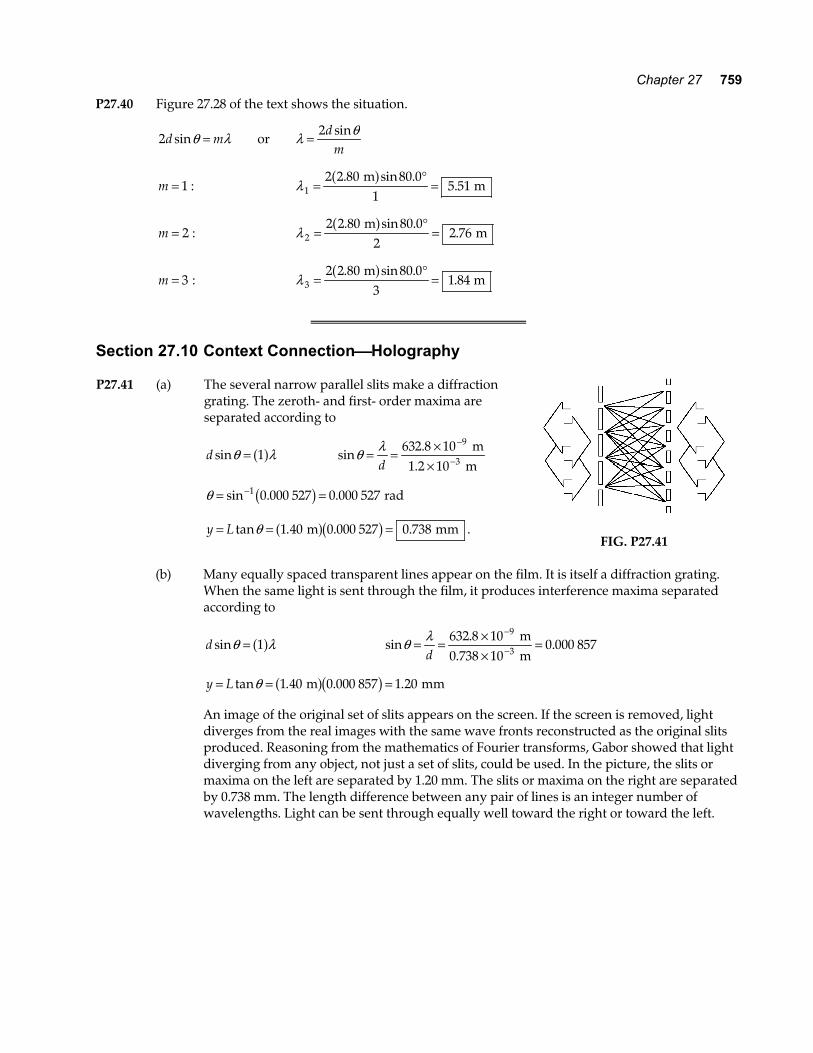
P27.41 (a) The several narrow parallel slits make a diffraction grating. The zeroth- and first- order maxima are separated according to
d sinθ λ= 1a f sin.θ λ= = ××
−
−d632 8 10 9
3 m
1.2 10 m
θ = =−sin . .1 0 000 527 0 000 527b g rad
y L= = =tan . . .θ 1 40 0 000 527 0 738 m mma fb g .
FIG. P27.41
(b) Many equally spaced transparent lines appear on the film. It is itself a diffraction grating.
When the same light is sent through the film, it produces interference maxima separated according to
d sinθ λ= 1a f sin.
.θ λ= = ××
=−
−d632 8 10
0 000 8579
3 m
0.738 10 m
y L= = =tan . . .θ 1 40 0 000 857 1 20 m mma fb g
An image of the original set of slits appears on the screen. If the screen is removed, light diverges from the real images with the same wave fronts reconstructed as the original slits produced. Reasoning from the mathematics of Fourier transforms, Gabor showed that light diverging from any object, not just a set of slits, could be used. In the picture, the slits or maxima on the left are separated by 1.20 mm. The slits or maxima on the right are separated by 0.738 mm. The length difference between any pair of lines is an integer number of wavelengths. Light can be sent through equally well toward the right or toward the left.
760 Wave Optics
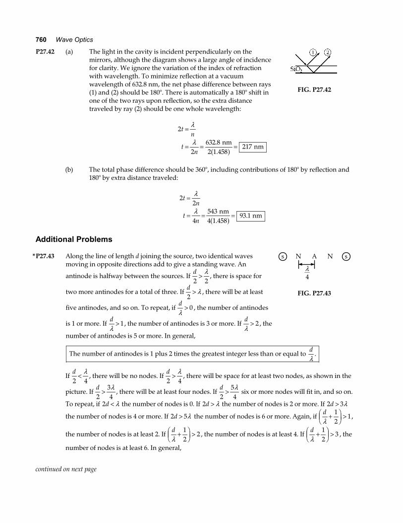
P27.42 (a) The light in the cavity is incident perpendicularly on the mirrors, although the diagram shows a large angle of incidence for clarity. We ignore the variation of the index of refraction with wavelength. To minimize reflection at a vacuum wavelength of 632.8 nm, the net phase difference between rays (1) and (2) should be 180°. There is automatically a 180° shift in one of the two rays upon reflection, so the extra distance traveled by ray (2) should be one whole wavelength:
FIG. P27.42
2
2632 8
217
tn
tn
=
= = =
λ
λ . nm2 1.458
nma f
(b) The total phase difference should be 360°, including contributions of 180° by reflection and
180° by extra distance traveled:
2
2
4543
93 1
tn
tn
=
= = =
λ
λ nm4 1.458
nma f .
Additional Problems
*P27.43 Along the line of length d joining the source, two identical waves moving in opposite directions add to give a standing wave. An
antinode is halfway between the sources. If d2 2
> λ, there is space for
two more antinodes for a total of three. If d2
> λ , there will be at least
five antinodes, and so on. To repeat, if dλ
> 0 , the number of antinodes
is 1 or more. If dλ
> 1, the number of antinodes is 3 or more. If dλ
> 2 , the
number of antinodes is 5 or more. In general,
s N A N s
λ4
FIG. P27.43
The number of antinodes is 1 plus 2 times the greatest integer less than or equal to dλ
.
If d2 4
< λ, there will be no nodes. If
d2 4
> λ, there will be space for at least two nodes, as shown in the
picture. If d2
34
> λ, there will be at least four nodes. If
d2
54
> λ six or more nodes will fit in, and so on.
To repeat, if 2d < λ the number of nodes is 0. If 2d > λ the number of nodes is 2 or more. If 2 3d > λ
the number of nodes is 4 or more. If 2 5d > λ the number of nodes is 6 or more. Again, if dλ
+FHGIKJ >
12
1,
the number of nodes is at least 2. If dλ
+FHGIKJ >
12
2 , the number of nodes is at least 4. If dλ
+FHGIKJ >
12
3 , the
number of nodes is at least 6. In general,
continued on next page
Chapter 27 761
the number of nodes is 2 times the greatest nonzero integer less than dλ
+FHGIKJ
12
.
Next, we enumerate the zones of constructive interference. They are described by d msinθ λ= , m = 0 1 2, , , K with θ counted as positive both left and right of the maximum at θ = 0 in the center.
The number of side maxima on each side is the greatest integer satisfying sinθ ≤ 1, d m1 ≥ λ , md≤λ
.
So the total
number of bright fringes is one plus 2 times the greatest integer less than or equal to dλ
.
It is equal to the number of antinodes on the line joining the sources.
The interference minima are to the left and right at angles described by d msinθ λ= +FHGIKJ
12
,
m = 0 1 2, , , K. With sinθ < 1, d m112
> +FHG
IKJmax λ , m
dmax < −
λ12
or md
max + < +112λ
. Let n = 1 2 3, , , K.
Then the number of side minima is the greatest integer n less than dλ
+ 12
. Counting both left and
right, the number of dark fringes is two times the greatest positive integer less than dλ
+FHGIKJ
12
. It is
equal to the number of nodes in the standing wave between the sources. P27.44 My middle finger has width d = 2 cm .
(a) Two adjacent directions of constructive interference for 600-nm light are described by
d msin
sin
θ λθ
θ
==
× = ×− −
0
21
7
0
2 10 1 6 10 m me j e j
Thus, θ 132 10= × − degree
and θ θ1 0310− −~ degree .
(b) Choose θ 1 20= °
2 10 20 1
7
2× ° =
=
− m
mm
e j a fsin λ
λ
Millimeter waves are microwaves .
fc=λ
: f =×× −
3 107 10
108
311 m s
m Hz~
762 Wave Optics
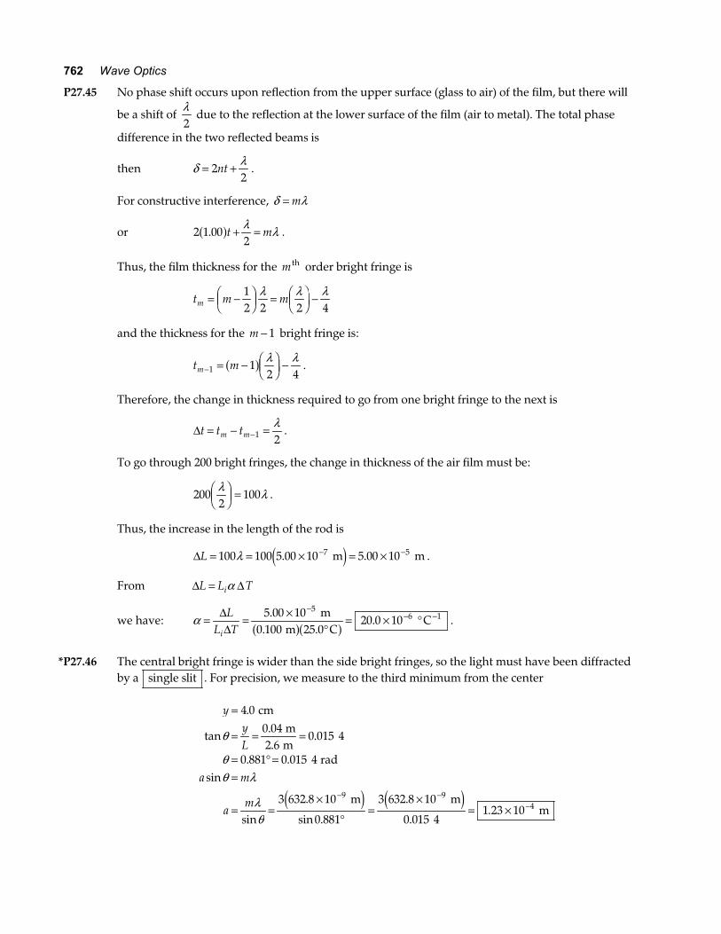
P27.45 No phase shift occurs upon reflection from the upper surface (glass to air) of the film, but there will
be a shift of λ2
due to the reflection at the lower surface of the film (air to metal). The total phase
difference in the two reflected beams is
then δ λ= +22
nt .
For constructive interference, δ λ= m
or 2 1 002
.a ft m+ =λ λ .
Thus, the film thickness for the m th order bright fringe is
t m mm = −FHGIKJ = FHG
IKJ −
12 2 2 4
λ λ λ
and the thickness for the m − 1 bright fringe is:
t mm− = − FHGIKJ −1 1
2 4a f λ λ
.
Therefore, the change in thickness required to go from one bright fringe to the next is
∆t t tm m= − =−1 2λ
.
To go through 200 bright fringes, the change in thickness of the air film must be:
2002
100λ λFHGIKJ = .
Thus, the increase in the length of the rod is
∆L = = × = ×− −100 100 5 00 10 5 00 107 5λ . . m me j .
From ∆ ∆L L Ti= α
we have: α = = ×°
= × °−
− −∆∆L
L Ti
5 00 100 100 25 0
20 0 105
6 1.. .
. m
m C Ca fa f .
*P27.46 The central bright fringe is wider than the side bright fringes, so the light must have been diffracted
by a single slit . For precision, we measure to the third minimum from the center
yyL
a m
am
=
= = =
= ° ==
= =×
°=
×= ×
− −−
4 00 042 6
0 015 4
0 881 0 015 4
3 632 8 10
0 881
3 632 8 10
0 015 41 23 10
9 94
.
tan..
.
. .sin
sin
.
sin .
.
..
cm m m
rad
m m m
θ
θθ λ
λθe j e j
Chapter 27 763
P27.47 For destructive interference, the path length must differ by mλ . We may treat this problem as a
double slit experiment if we remember the light undergoes a π2
-phase shift at the mirror. The
second slit is the mirror image of the source, 1.00 cm below the mirror plane. Modifying the equation
for Young’s experiment, dyL
m= λ we have
ym L
ddark
m m
m mm= =
×
×=
−
−
λ 1 5 00 10 100
2 00 102 50
7
2
.
..
e ja fe j
.
P27.48 2 15 0 30 1752 2. . km kma f + =h
15 0 227 63
1 62
2 2. .
.
km
km
a f + =
=
h
h
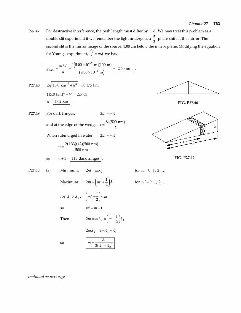
FIG. P27.48 P27.49 For dark fringes, 2nt m= λ
and at the edge of the wedge, t =84 500
2 nma f
.
When submerged in water, 2nt m= λ
m =2 1 33 42 500
500.a fa fa f nm
nm
so m + =1 113 dark fringes .
FIG. P27.49
P27.50 (a) Minimum: 2 2nt m= λ for m = 0 1 2, , , K
Maximum: 212 1nt m= ′ +FHGIKJλ for ′ =m 0 1 2, , , K
for λ λ1 2> , ′ +FHGIKJ <m m
12
so ′ = −m m 1 .
Then 2122 1nt m m= = −FHGIKJλ λ
2 22 1 1m mλ λ λ= −
so m =−
λλ λ
1
1 22b g .
continued on next page
764 Wave Optics
(b) m =−
= →5002 500 370
1 92 2a f . (wavelengths measured to ±5 nm )
Minimum: 2 2nt m= λ
2 1 40 2 370.a f a ft = nm t = 264 nm
Maximum: 2 112
1 5nt m= − +FHG
IKJ =λ λ.
2 1 40 1 5 500. .a f a ft = nm t = 268 nm
Film thickness = 266 nm .
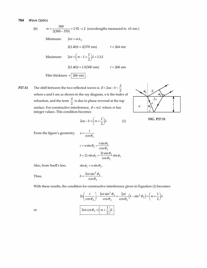
P27.51 The shift between the two reflected waves is δ λ= − −22
na b
where a and b are as shown in the ray diagram, n is the index of
refraction, and the term λ2
is due to phase reversal at the top
surface. For constructive interference, δ λ= m where m has integer values. This condition becomes
212
na b m− = +FHGIKJλ (1)
From the figure’s geometry, at=
cosθ 2
FIG. P27.51
c a
t
b ct
= =
= =
sinsin
cos
sinsin
cossin
θ θθ
φ θθ
φ
22
2
12
212
2
Also, from Snell’s law, sin sinφ θ1 2= n .
Thus, bnt
=2 2
2
2
sincos
θθ
.
With these results, the condition for constructive interference given in Equation (1) becomes:
22 2
1122
22
2 2
22n
t nt ntm
cossin
cos cossin
θθ
θ θθ λ
FHG
IKJ − = − = +FHG
IKJe j
or 2122nt mcosθ λ= +FHGIKJ .
Chapter 27 765
P27.52 (a) Bright bands are observed when 212
nt m= +FHGIKJλ .
Hence, the first bright band ( m = 0 ) corresponds to nt = λ4
.
Since xx
tt
1
2
1
2=
we have x xtt
x2 12
11
2
13 00
6804 86=
FHGIKJ =FHGIKJ =
FHG
IKJ =
λλ
. . cm nm
420 nm cma f .
(b) tn11
4420
78 9= = =λ nm
4 1.33 nma f .
tn22
4680
128= = =λ nm
4 1.33 nma f
(c) θ θ≈ = = = × −tan.
.tx
1
1
678 92 63 10
nm3.00 cm
rad
P27.53 The first minimum is at a sinθ λ= 1a f .
This has no solution if λa
> 1 .
or if a < =λ 632 8. nm .
P27.54 Consider vocal sound moving at 340 m/s and of frequency 3 000 Hz. Its wavelength is
λ = = =vf
3403 000
0 113 m s
Hz m. .
If your mouth, for horizontal dispersion, behaves similarly to a slit 6.00 cm wide, then a msinθ λ= predicts no diffraction minima. You are a nearly isotropic source of this sound. It spreads out from you nearly equally in all directions. On the other hand, if you use a megaphone with width 60.0 cm at its wide end, then a msinθ λ= predicts the first diffraction minimum at
θ λ= FHGIKJ =
FHG
IKJ = °− −sin sin
..1 1 0 113
10 9ma
m0.600 m
.
This suggests that the sound is radiated mostly toward the front into a diverging beam of angular diameter only about 20°. With less sound energy wasted in other directions, more is available for your intended auditors. We could check that a distant observer to the side or behind you receives less sound when a megaphone is used.
766 Wave Optics
P27.55 d = = ×−−1
4002 50 101
6
mm m.
(a) d msinθ λ= θ a = × ××
FHG
IKJ = °−
−
−sin .19
62 541 10
25 6 m
2.50 10 m
(b) λ = × = ×−
−541 104 07 10
97 m
1.33 m. θ b = × ×
×FHG
IKJ = °−
−
−sin.
.17
62 4 07 10
19 0 m
2.50 10 m
(c) d asinθ λ= 2 dnbsinθ λ= 2
n b asin sinθ θ= 1a f
P27.56 (a) λ = vf
: λ =××
=−3 00 101 40 10
0 2148
9 1
..
. m ss
m
θ λmin .= 1 22
D: θ µmin .
..=
×FHG
IKJ =1 22
0 2147 26
m3.60 10 m
rad4
θ µπmin . .= × ×F
HGIKJ =7 26
180 60 601 50 rad
s arc seconds
(b) θ min = dL
: d L= = × =−θ min . .7 26 10 26 000 0 1896 rad ly lye jb g
(c) θ λmin .= 1 22
D θ µmin . . .= ×
×FHG
IKJ =
−
−1 22500 10
50 8 10 59
3 m
12.0 10 m rad seconds of arca f
(d) d L= = × = × =− −θ min . . . .50 8 10 30 0 1 52 10 1 526 3 rad m m mme ja f
P27.57 (a) d msinθ λ=
or dm= =
×
°=
−λθ
µsin sin .
.3 500 10
32 02 83
9 m m
e j
Therefore, lines per unit length = =× −
1 12 83 10 6d . m
or lines per unit length = × = ×− −3 53 10 3 53 105 1 3 1. . m cm .
continued on next page
Chapter 27 767
(b) sin.
.θ λ= =×
×=
−
−md
mm
500 10
2 83 100 177
9
6
m
m
e j a f
For sin .θ ≤ 1 00 , we must have m 0 177 1 00. .a f ≤
or m ≤ 5 66. .
Therefore, the highest order observed is m = 5 .
Total number of primary maxima observed is 2 1 11m + = .
*P27.58 (a) Bragg’s law applies to the space lattice of melanin rods. Consider the planes d = 0 25. mµ
apart. For light at near-normal incidence, strong reflection happens for the wavelength given by 2d msinθ λ= . The longest wavelength reflected strongly corresponds to m = 1:
2 0 25 10 90 16. sin× ° =− me j λ λ = 500 nm. This is the blue-green color.
(b) For light incident at grazing angle 60°, 2d msinθ λ= gives
1 2 0 25 10 60 4336λ = × ° =−. sin m nme j . This is violet.
(c) Your two eyes receive light reflected from the feather at different angles, so they receive
light incident at different angles and containing different colors reinforced by constructive interference.
(d) The longest wavelength that can be reflected with extra strength by these melanin rods is
the one we computed first, 500 nm blue-green. (e) If the melanin rods were farther apart (say 0 32. mµ ) they could reflect red with constructive
interference.
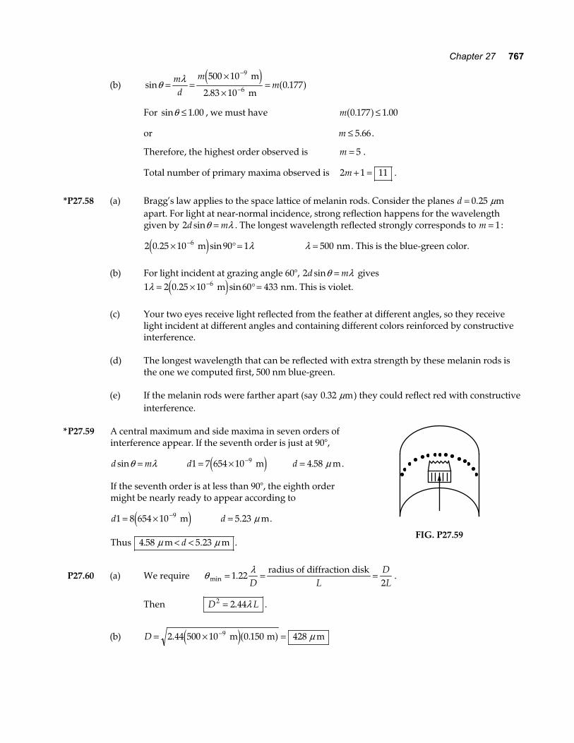
*P27.59 A central maximum and side maxima in seven orders of interference appear. If the seventh order is just at 90°,
d msinθ λ= d1 7 654 10 9= × − me j d = 4 58. mµ .
If the seventh order is at less than 90°, the eighth order might be nearly ready to appear according to
d1 8 654 10 9= × − me j d = 5 23. mµ .
Thus 4 58 5 23. . m mµ µ< <d .
FIG. P27.59
P27.60 (a) We require θ λmin .= = =1 22
2D LDL
radius of diffraction disk.
Then D L2 2 44= . λ .
(b) D = × =−2 44 500 10 0 150 4289. . m m me ja f µ
768 Wave Optics
P27.61 d msinθ λ=
and, differentiating, d d mdcosθ θ λa f =
or d m1 2− ≈sin θ θ λ∆ ∆
dm
dm1
2 2
2− ≈λ θ λ∆ ∆
so ∆ ∆θ λ
λ≈
−d m2 2 2e j.
ANSWERS TO EVEN PROBLEMS P27.2 (a) 36.2°; (b) 5.08 cm; (c) 508 THz P27.4 maxima at 0°, 29.1°, and 76.3°; minima at
14.1° and 46.8° P27.6 11.3 m P27.8 (a) 10.0 m; (b) 516 m; (c) Only the runway centerline is a
maximum for the interference patterns for both frequencies. If the frequencies were
related by a ratio of small integers kl
, the
plane could by mistake fly along the k-th side maximum of one signal where it coincides with the l-th side maximum of the other.
P27.10 see the solution P27.12 (a) 1.29 rad; (b) 99.6 nm P27.14 612 nm P27.16 0.500 cm P27.18 (a) 238 nm; (b) λ increase; (c) 328 nm P27.20 4.22 mm P27.22 547 nm P27.24 three maxima, at 0° and near 46° on both
sides
P27.26 1.00 mrad P27.28 she can resolve only the violet tubes if she
is between 186 m and 271 m away P27.30 neither, it can resolve objects no closer
than several centimeters apart P27.32 514 nm P27.34 1 81. mµ 1.81 m P27.36 see the solution P27.38 93.4 pm P27.40 5.51 m, 2.76 m, 1.84 m P27.42 (a) 217 nm; (b) 93.1 nm P27.44 (a) ~10 3− degree ; (b) ~1011 Hz, microwave P27.46 one slit 0.123 mm wide P27.48 1.62 km P27.50 (a) see the solution; (b) 266 nm P27.52 (a) 4.86 cm from the top; (b) 78.9 nm and 128 nm; (c) 2 63 10 6. × − rad P27.54 see the solution
Chapter 27 769
P27.56 (a) 7 26. radµ (1.50 seconds of arc); (b) 0.189 ly; (c) 50 8. radµ (10.5 seconds of arc); (d) 1.52 mm
P27.58 see the solution P27.60 (a) D L2 2 44= . λ ; (b) 0.428 mm
CONTEXT 8 CONCLUSION SOLUTIONS TO PROBLEMS CC8.1 Depth = one-quarter of the wavelength in plastic.
tn
= = =λ4
780130
nm4 1.50
nma f
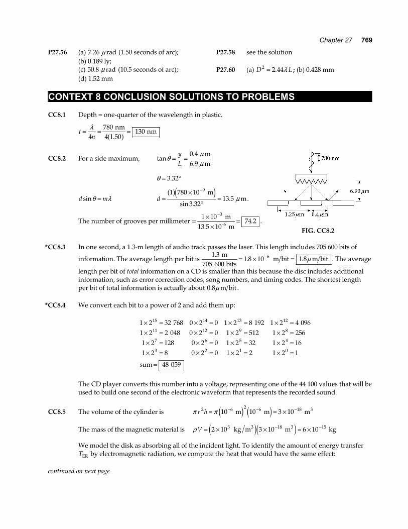
CC8.2 For a side maximum, tan.θ µ
µ= =
yL
0 4 m6.9 m
θ = °3 32.
d msinθ λ= d =×
°=
−1 780 10
3 3213 5
9a fe j m m
sin .. µ .
The number of grooves per millimeter = ××
=−1 10
74 23 m
13.5 10 m-6 . . FIG. CC8.2
*CC8.3 In one second, a 1.3-m length of audio track passes the laser. This length includes 705 600 bits of
information. The average length per bit is 1 3
705 6001 8 10 1 86.. .
mbits
m bit m bit= × =− µ . The average
length per bit of total information on a CD is smaller than this because the disc includes additional information, such as error correction codes, song numbers, and timing codes. The shortest length per bit of total information is actually about 0 8. µ m bit .
*CC8.4 We convert each bit to a power of 2 and add them up:
1 2 32 768 0 2 0 1 2 8 192 1 2 4 0961 2 2 048 0 2 0 1 2 512 1 2 2561 2 128 0 2 0 1 2 32 1 2 161 2 8 0 2 0 1 2 2 1 2 1
48 059
15 14 13 12
11 12 9 8
7 6 5 4
3 2 1 0
× = × = × = × =× = × = × = × =× = × = × = × =× = × = × = × =
=
sum
The CD player converts this number into a voltage, representing one of the 44 100 values that will be
used to build one second of the electronic waveform that represents the recorded sound.
CC8.5 The volume of the cylinder is π πr h2 610= ≈ ×− − − m 10 m 3 10 m2 6 18 3e j e j
The mass of the magnetic material is ρ V = × × ≈ ×− −2 10 3 10 6 103 18 15 kg m m kg3 3e je j
We model the disk as absorbing all of the incident light. To identify the amount of energy transfer TER by electromagnetic radiation, we compute the heat that would have the same effect:
continued on next page
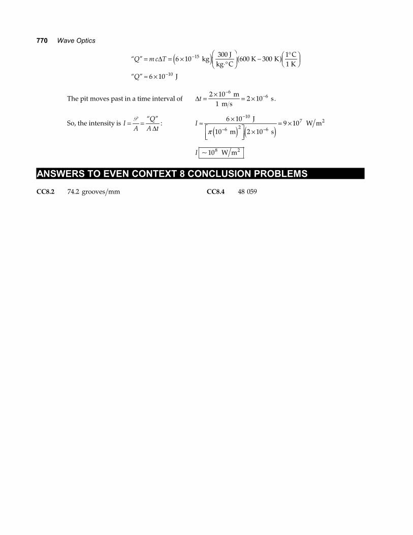
770 Wave Optics
“ ”
“ ”
Q m c T
Q
= = ×⋅°
FHG
IKJ − °F
HGIKJ
≈ ×
−
−
∆ 6 10 30011
15 kg300 J
kg C600 K K
C K
6 10 J10
e j a f
The pit moves past in a time interval of ∆t = × = ×−
−2 101
2 106
6 m m s
s.
So, the intensity is IA
QA t
= =P “ ”∆
: I ≈ ×LNM
OQP ×
= ×−
− −
6 10
2 109 10
10
2 6
7 J
10 m s W m
6
2
π e j e j
I ~108 W m2
ANSWERS TO EVEN CONTEXT 8 CONCLUSION PROBLEMS CC8.2 74.2 grooves mm CC8.4 48 059