Embed Size (px)
Citation preview
... WaveACCESS LINK Antenna OptionsORiNOCO Technical Bulletin 026 / A September 1999
TB-026.doc Copyright © 1999, 2000, 2001 Agere Systems Page 1 of 19
Note: The information in this bulletin relates to older implementation of the currenttechnology. Since the creation of this bulletin products have evolved and nameshave changed. Rather then removing this document it is kept in the set of bulletinswith this note, because the information in it has educational value.
Introduction
This bulletin is prepared to assist installers of outdoor antenna products in selectingthe right antenna for their Lucent Technologies outdoor wireless LAN solution.
Lucent Technologies wireless outdoor solution are referred to as:
• WaveACCESS LINK WP-II
• WaveACCESS CAMPUS
• WaveACCESS NET
• WaveACCESS LINK BR132
• WaveACCESS LINK SM1024
The first two products listed above are based on WavePOINT-II, while the latterthree use a different platform. This bulletin covers the difference between thevarious options, and explains which antenna to use with which product.
Please Note: The Lucent Technologies WaveACCESS Antennas havebeen developed for very specific combinations of bridge hardwareand radio technologies. For optimal performance and compliance withlocal radio regulations, only use the antenna identified for eachspecific bridge product.
WavePOINT-II based Options
The antennas described in this section are designed for usage in combination with:
� WavePOINT-II Access Points
� WaveACCESS LINK WP-II*
� WaveACCESS CAMPUS**
WavePOINT-II Antenna Options
Following antenna options are available for WaveLAN systems:
* Formerly referred to as WavePOINT-II Point-to-Point (PTP) bridge.** Formerly referred to as WaveCAMPUS.
... WaveACCESS LINK Antenna Options
TB-026.doc Copyright © 1999, 2000, 2001 Agere Systems Page 2 of 19
� Directional Yagi antenna
� Omni-Directional Pole Antennas
WavePOINT-II Directional Antennas
Directional antennas provide a large range, but require exact alignment of antennasat both ends of a wireless link.
... WaveACCESS LINK Antenna Options
TB-026.doc Copyright © 1999, 2000, 2001 Agere Systems Page 3 of 19
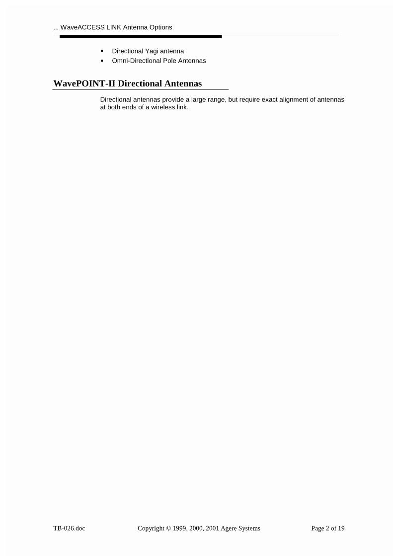
14 dBi Directional Yagi Antenna
Gain 14 dBi
Horizontal 31.4 DegreesBeam width
Vertical 30.8 Degrees
Dimensions 18"/45.7 cm
Mounting Mounts on a 1.125-1.625inch OD mast
Connector type Type N male*
Polarization Horizontal & Vertical
Please Note: Subject to the country where this antenna will be used, you may needto apply a special WaveLAN card in order to comply with local radio regulations.
� In countries that adhere to radio regulations as defined by the FederalCommunications Commission (FCC) you can connect this antenna to anyWaveLAN card.
� In countries that adhere to radio regulations as defined by the EuropeanTelecommunications Standards Institute (ETSI) you may only connect thisantenna to your WaveLAN system when using the Red-Colored Fixed WirelessPC Card.
It is the responsibility of the end-user to ensure that the outdoor installationcomplies with local radio regulations. Lucent Technologies is not liable for anydamage or judicial claim resulting from failing to comply with such regulations.
WavePOINT-II Omni-Directional Antennas
Omni- Directional antennas allow for easy installation and alignment, but may notprovide as large a coverage as directional antennas.
Following Omni-directional antennas are available for WaveLAN outdoor antennainstallations.
� 7 dBi Omni-directional pole antenna
� 5 dBi Omni-directional Vehicle Mount antenna
* Previously released WaveLAN products in the US came with a different
connector type referred to as Reverse Polarity-N.
... WaveACCESS LINK Antenna Options
TB-026.doc Copyright © 1999, 2000, 2001 Agere Systems Page 4 of 19
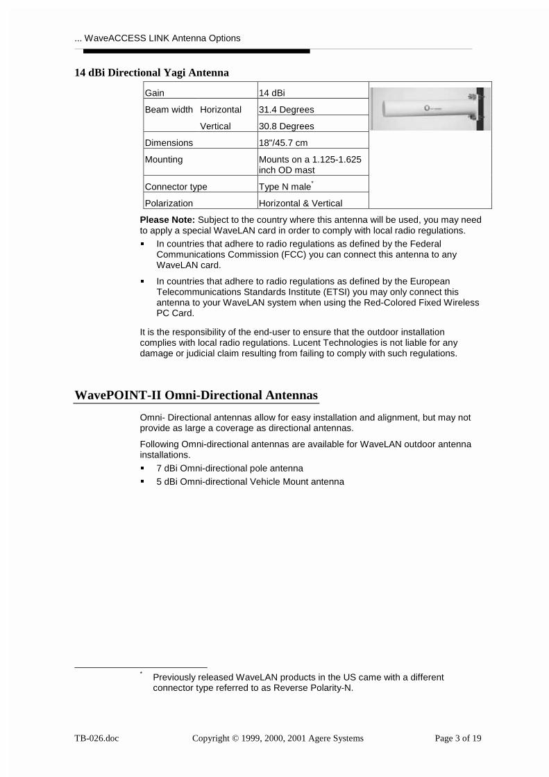
7 dBi Omni-directional Pole Antenna
Gain 7 dBi
Horizontal 360 DegreesBeam width
Vertical ?? Degrees
Dimensions 18"/45.7 cm
Mounting Mounts on a 1.4-2.6 inchOD mast
Connector type Type N male*
Polarization Vertical
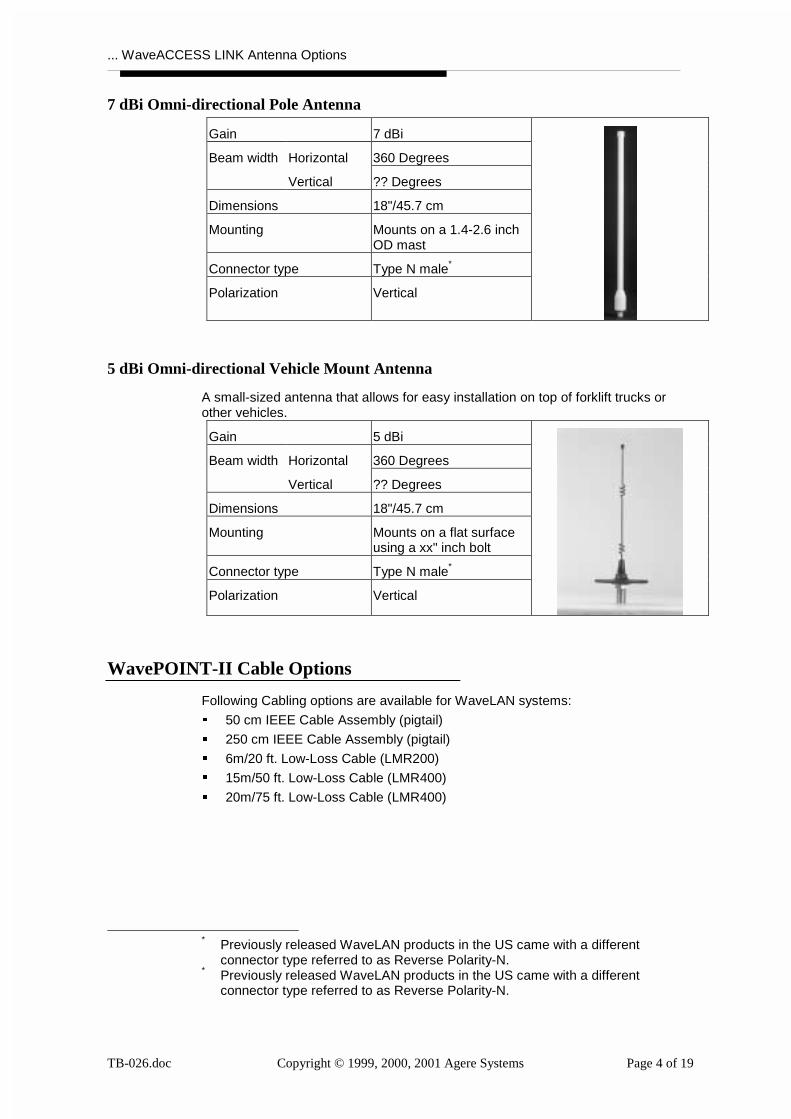
5 dBi Omni-directional Vehicle Mount Antenna
A small-sized antenna that allows for easy installation on top of forklift trucks orother vehicles.
Gain 5 dBi
Horizontal 360 DegreesBeam width
Vertical ?? Degrees
Dimensions 18"/45.7 cm
Mounting Mounts on a flat surfaceusing a xx" inch bolt
Connector type Type N male*
Polarization Vertical
WavePOINT-II Cable Options
Following Cabling options are available for WaveLAN systems:
� 50 cm IEEE Cable Assembly (pigtail)
� 250 cm IEEE Cable Assembly (pigtail)
� 6m/20 ft. Low-Loss Cable (LMR200)
� 15m/50 ft. Low-Loss Cable (LMR400)
� 20m/75 ft. Low-Loss Cable (LMR400)
* Previously released WaveLAN products in the US came with a different
connector type referred to as Reverse Polarity-N.* Previously released WaveLAN products in the US came with a different
connector type referred to as Reverse Polarity-N.
... WaveACCESS LINK Antenna Options
TB-026.doc Copyright © 1999, 2000, 2001 Agere Systems Page 5 of 19
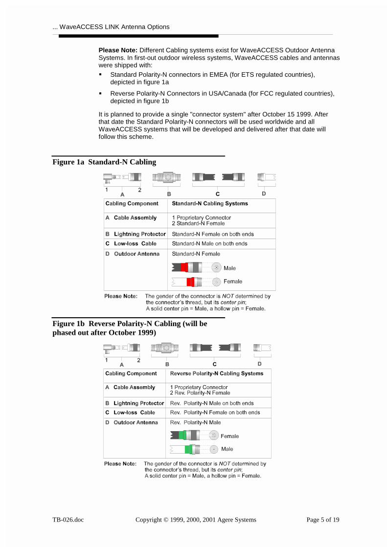
Please Note: Different Cabling systems exist for WaveACCESS Outdoor AntennaSystems. In first-out outdoor wireless systems, WaveACCESS cables and antennaswere shipped with:
� Standard Polarity-N connectors in EMEA (for ETS regulated countries),depicted in figure 1a
� Reverse Polarity-N Connectors in USA/Canada (for FCC regulated countries),depicted in figure 1b
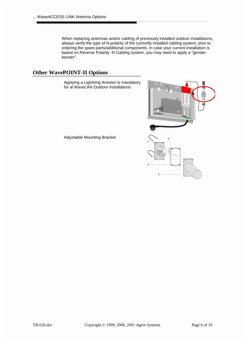
It is planned to provide a single "connector system" after October 15 1999. Afterthat date the Standard Polarity-N connectors will be used worldwide and allWaveACCESS systems that will be developed and delivered after that date willfollow this scheme.
Figure 1a Standard-N Cabling
Figure 1b Reverse Polarity-N Cabling (will bephased out after October 1999)
... WaveACCESS LINK Antenna Options
TB-026.doc Copyright © 1999, 2000, 2001 Agere Systems Page 6 of 19
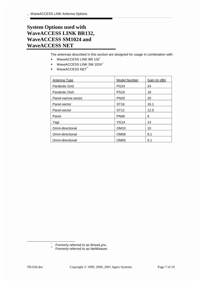
When replacing antennas and/or cabling of previously installed outdoor installations,always verify the type of N-polarity of the currently installed cabling system, prior toordering the spare-parts/additional components. In case your current installation isbased on Reverse Polarity -N Cabling system, you may need to apply a "gender-bender".
Other WavePOINT-II Options
Applying a Lightning Arrestor is mandatoryfor al WaveLAN Outdoor Installations
Adjustable Mounting Bracket
... WaveACCESS LINK Antenna Options
TB-026.doc Copyright © 1999, 2000, 2001 Agere Systems Page 7 of 19
System Options used withWaveACCESS LINK BR132,WaveACCESS SM1024 andWaveACCESS NET
The antennas described in this section are designed for usage in combination with:
� WaveACCESS LINK BR 132*
� WaveACCESS LINK SM 1024∗
� WaveACCESS NET**
Antenna Type Model Number Gain (in dBi)
Parabolic Grid PG24 24
Parabolic Dish PS19 19
Panel-narrow sector PN20 20
Panel-sector ST16 16.1
Panel-sector ST12 12.5
Panel PN06 6
Yagi YG14 14
Omni-directional OM10 10
Omni-directional OM08 8.1
Omni-directional OM05 5.1
* Formerly referred to as WaveLynx.** Formerly referred to as NetWeaver.
... WaveACCESS LINK Antenna Options
TB-026.doc Copyright © 1999, 2000, 2001 Agere Systems Page 8 of 19
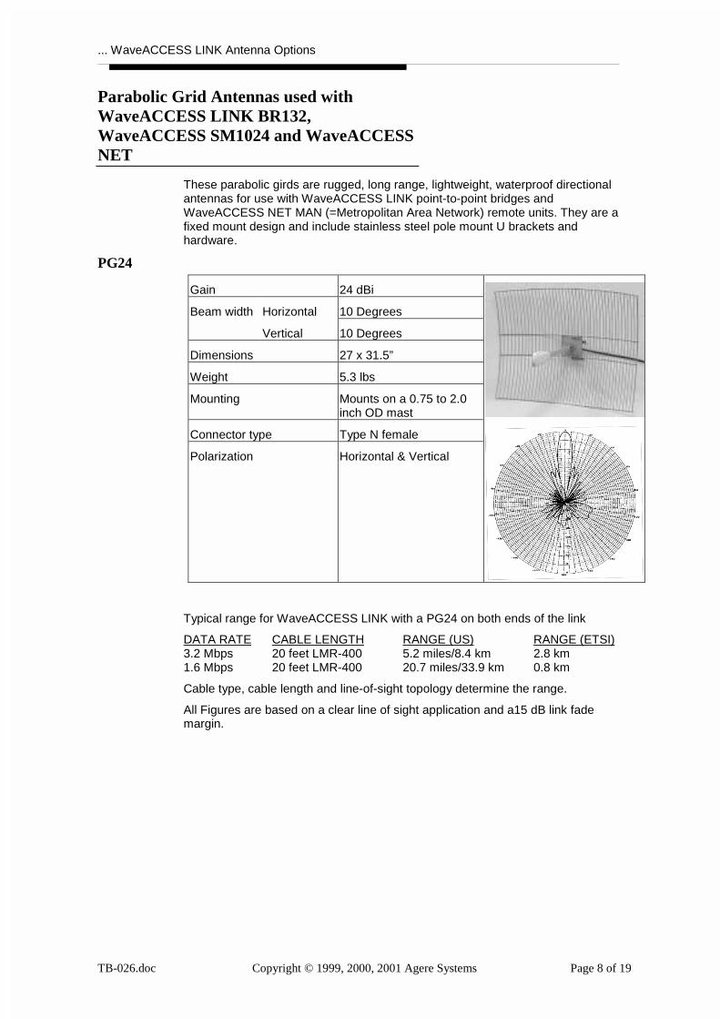
Parabolic Grid Antennas used withWaveACCESS LINK BR132,WaveACCESS SM1024 and WaveACCESSNET
These parabolic girds are rugged, long range, lightweight, waterproof directionalantennas for use with WaveACCESS LINK point-to-point bridges andWaveACCESS NET MAN (=Metropolitan Area Network) remote units. They are afixed mount design and include stainless steel pole mount U brackets andhardware.
PG24
Gain 24 dBi
Horizontal 10 DegreesBeam width
Vertical 10 Degrees
Dimensions 27 x 31.5”
Weight 5.3 lbs
Mounting Mounts on a 0.75 to 2.0inch OD mast
Connector type Type N female
Polarization Horizontal & Vertical
Typical range for WaveACCESS LINK with a PG24 on both ends of the link
DATA RATE CABLE LENGTH RANGE (US) RANGE (ETSI)3.2 Mbps 20 feet LMR-400 5.2 miles/8.4 km 2.8 km1.6 Mbps 20 feet LMR-400 20.7 miles/33.9 km 0.8 km
Cable type, cable length and line-of-sight topology determine the range.
All Figures are based on a clear line of sight application and a15 dB link fademargin.
... WaveACCESS LINK Antenna Options
TB-026.doc Copyright © 1999, 2000, 2001 Agere Systems Page 9 of 19
Parabolic Dish Antennas used withWaveACCESS LINK BR132,WaveACCESS SM1024 and WaveACCESSNET
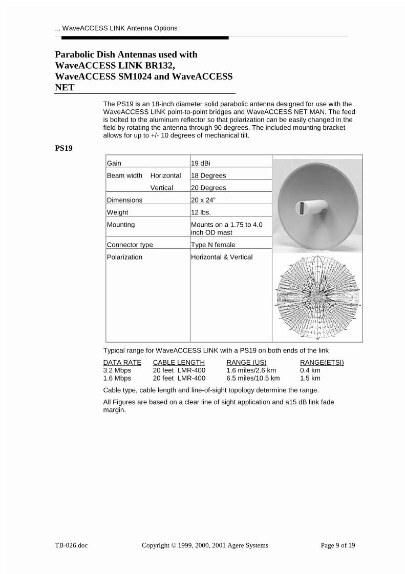
The PS19 is an 18-inch diameter solid parabolic antenna designed for use with theWaveACCESS LINK point-to-point bridges and WaveACCESS NET MAN. The feedis bolted to the aluminum reflector so that polarization can be easily changed in thefield by rotating the antenna through 90 degrees. The included mounting bracketallows for up to +/- 10 degrees of mechanical tilt.
PS19
Gain 19 dBi
Horizontal 18 DegreesBeam width
Vertical 20 Degrees
Dimensions 20 x 24”
Weight 12 lbs.
Mounting Mounts on a 1.75 to 4.0inch OD mast
Connector type Type N female
Polarization Horizontal & Vertical
Typical range for WaveACCESS LINK with a PS19 on both ends of the link
DATA RATE CABLE LENGTH RANGE (US) RANGE(ETSI)3.2 Mbps 20 feet LMR-400 1.6 miles/2.6 km 0.4 km1.6 Mbps 20 feet LMR-400 6.5 miles/10.5 km 1.5 km
Cable type, cable length and line-of-sight topology determine the range.
All Figures are based on a clear line of sight application and a15 dB link fademargin.
... WaveACCESS LINK Antenna Options
TB-026.doc Copyright © 1999, 2000, 2001 Agere Systems Page 10 of 19
Panel, Narrow Sector Antennas used withWaveACCESS LINK BR132,WaveACCESS SM1024 and WaveACCESSNET
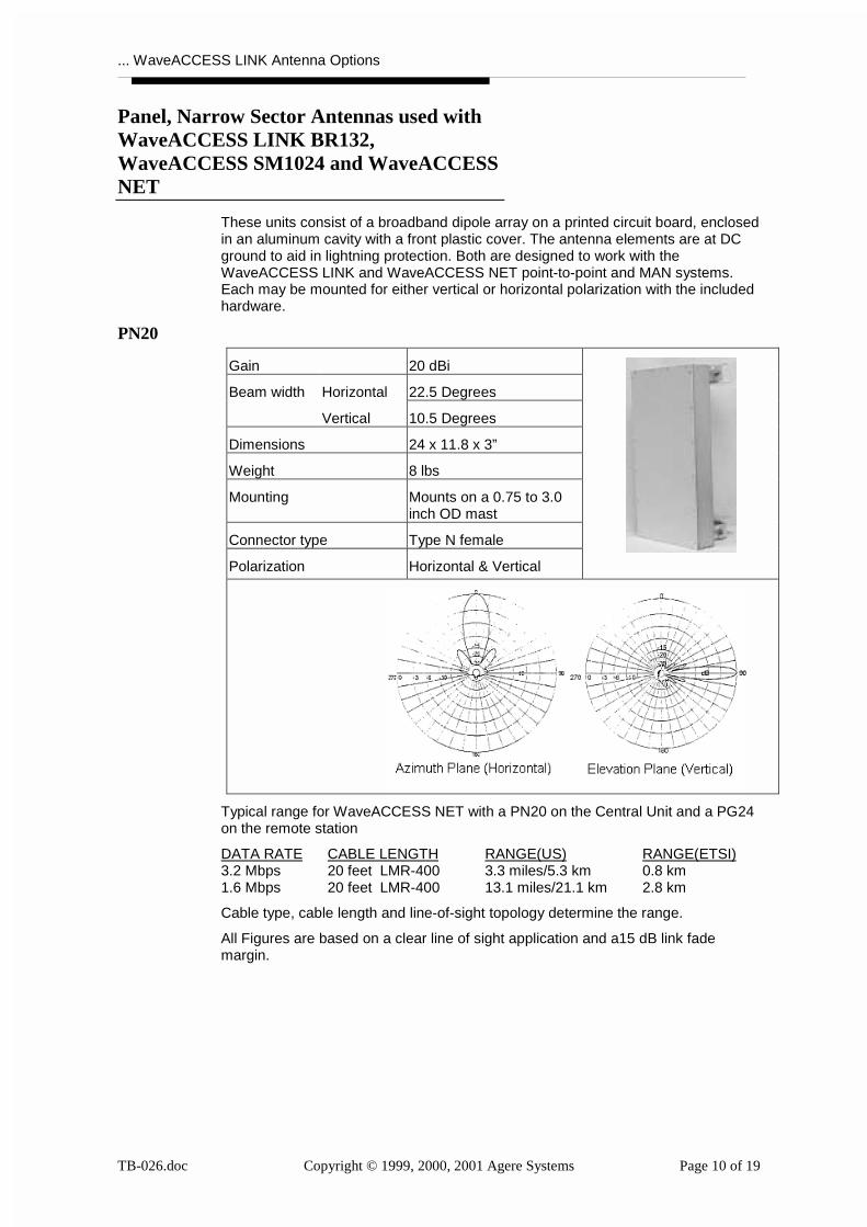
These units consist of a broadband dipole array on a printed circuit board, enclosedin an aluminum cavity with a front plastic cover. The antenna elements are at DCground to aid in lightning protection. Both are designed to work with theWaveACCESS LINK and WaveACCESS NET point-to-point and MAN systems.Each may be mounted for either vertical or horizontal polarization with the includedhardware.
PN20
Gain 20 dBi
Horizontal 22.5 DegreesBeam width
Vertical 10.5 Degrees
Dimensions 24 x 11.8 x 3”
Weight 8 lbs
Mounting Mounts on a 0.75 to 3.0inch OD mast
Connector type Type N female
Polarization Horizontal & Vertical
Typical range for WaveACCESS NET with a PN20 on the Central Unit and a PG24on the remote station
DATA RATE CABLE LENGTH RANGE(US) RANGE(ETSI)3.2 Mbps 20 feet LMR-400 3.3 miles/5.3 km 0.8 km1.6 Mbps 20 feet LMR-400 13.1 miles/21.1 km 2.8 km
Cable type, cable length and line-of-sight topology determine the range.
All Figures are based on a clear line of sight application and a15 dB link fademargin.
... WaveACCESS LINK Antenna Options
TB-026.doc Copyright © 1999, 2000, 2001 Agere Systems Page 11 of 19
Panel Sector Antennas used withWaveACCESS LINK BR132,WaveACCESS SM1024 and WaveACCESSNET
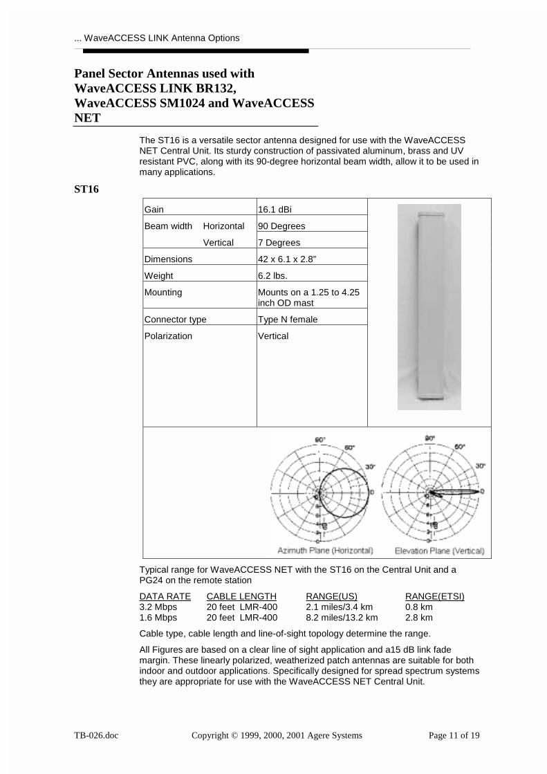
The ST16 is a versatile sector antenna designed for use with the WaveACCESSNET Central Unit. Its sturdy construction of passivated aluminum, brass and UVresistant PVC, along with its 90-degree horizontal beam width, allow it to be used inmany applications.
ST16
Gain 16.1 dBi
Horizontal 90 DegreesBeam width
Vertical 7 Degrees
Dimensions 42 x 6.1 x 2.8”
Weight 6.2 lbs.
Mounting Mounts on a 1.25 to 4.25inch OD mast
Connector type Type N female
Polarization Vertical
Typical range for WaveACCESS NET with the ST16 on the Central Unit and aPG24 on the remote station
DATA RATE CABLE LENGTH RANGE(US) RANGE(ETSI)3.2 Mbps 20 feet LMR-400 2.1 miles/3.4 km 0.8 km1.6 Mbps 20 feet LMR-400 8.2 miles/13.2 km 2.8 km
Cable type, cable length and line-of-sight topology determine the range.
All Figures are based on a clear line of sight application and a15 dB link fademargin. These linearly polarized, weatherized patch antennas are suitable for bothindoor and outdoor applications. Specifically designed for spread spectrum systemsthey are appropriate for use with the WaveACCESS NET Central Unit.
... WaveACCESS LINK Antenna Options
TB-026.doc Copyright © 1999, 2000, 2001 Agere Systems Page 12 of 19
ST12
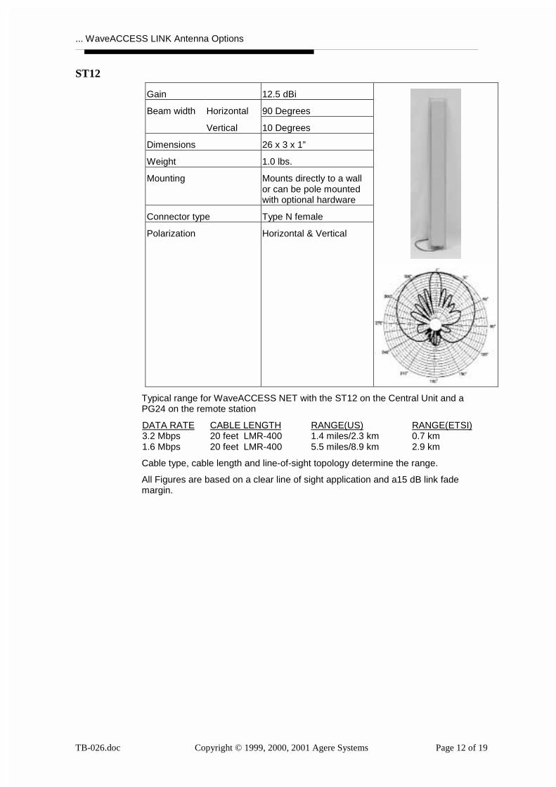
Gain 12.5 dBi
Horizontal 90 DegreesBeam width
Vertical 10 Degrees
Dimensions 26 x 3 x 1”
Weight 1.0 lbs.
Mounting Mounts directly to a wallor can be pole mountedwith optional hardware
Connector type Type N female
Polarization Horizontal & Vertical
Typical range for WaveACCESS NET with the ST12 on the Central Unit and aPG24 on the remote station
DATA RATE CABLE LENGTH RANGE(US) RANGE(ETSI)3.2 Mbps 20 feet LMR-400 1.4 miles/2.3 km 0.7 km1.6 Mbps 20 feet LMR-400 5.5 miles/8.9 km 2.9 km
Cable type, cable length and line-of-sight topology determine the range.
All Figures are based on a clear line of sight application and a15 dB link fademargin.

... WaveACCESS LINK Antenna Options
TB-026.doc Copyright © 1999, 2000, 2001 Agere Systems Page 13 of 19
PN06
Gain 6 dB
Horizontal 75 DegreesBeam width
Vertical 65 Degrees
Dimensions 5 x 5 x 1”
Weight 0.5 lbs.
Mounting Mounts directly to a wall
Connector type Type N female
Polarization Horizontal & Vertical
Typical range for WaveACCESS NET with the PN06 on the Central Unit and aPG24 on the remote station
DATA RATE CABLE LENGTH RANGE(US) RANGE(ETSI)3.2 Mbps 20 feet LMR-400 0.4 miles/0.6 km 0.4 km1.6 Mbps 20 feet LMR-400 1.6 miles/2.6 km 1.7 km
Cable type, cable length and line-of-sight topology determine the range.
All Figures are based on a clear line of sight application and a15 dB link fademargin.
... WaveACCESS LINK Antenna Options
TB-026.doc Copyright © 1999, 2000, 2001 Agere Systems Page 14 of 19
Yagi Antennas used with WaveACCESSLINK BR132, WaveACCESS SM1024 andWaveACCESS NET
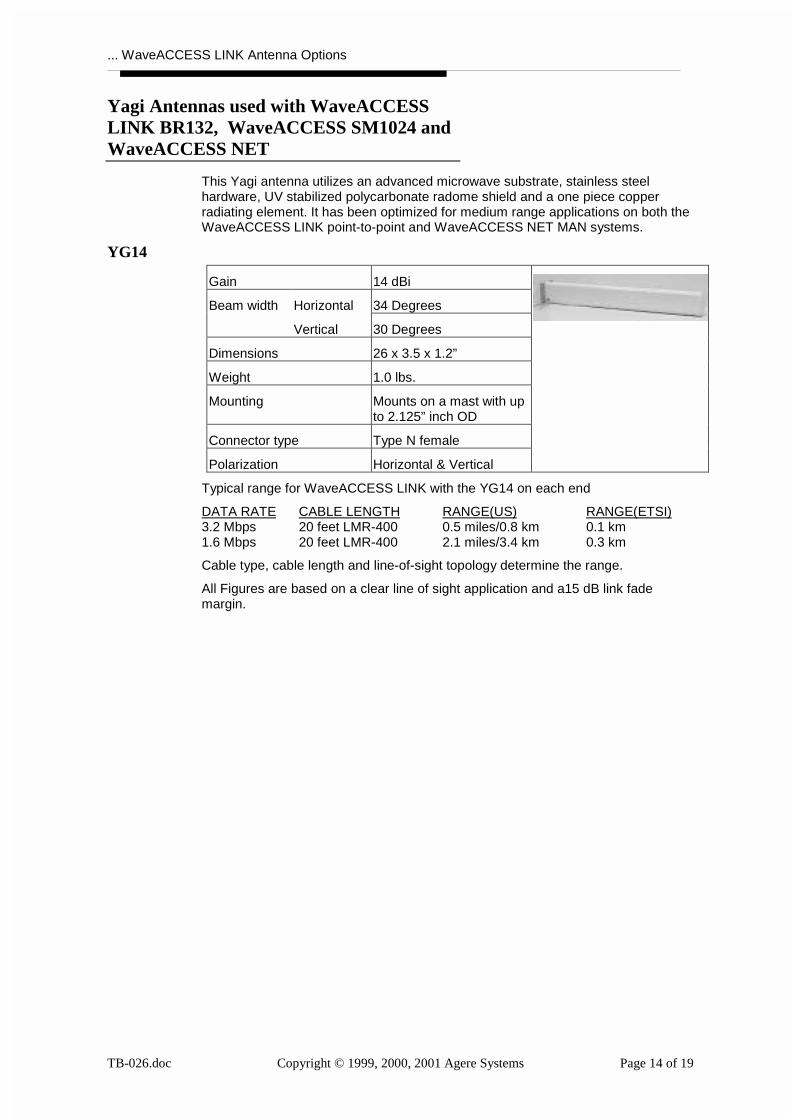
This Yagi antenna utilizes an advanced microwave substrate, stainless steelhardware, UV stabilized polycarbonate radome shield and a one piece copperradiating element. It has been optimized for medium range applications on both theWaveACCESS LINK point-to-point and WaveACCESS NET MAN systems.
YG14
Gain 14 dBi
Horizontal 34 DegreesBeam width
Vertical 30 Degrees
Dimensions 26 x 3.5 x 1.2”
Weight 1.0 lbs.
Mounting Mounts on a mast with upto 2.125” inch OD
Connector type Type N female
Polarization Horizontal & Vertical
Typical range for WaveACCESS LINK with the YG14 on each end
DATA RATE CABLE LENGTH RANGE(US) RANGE(ETSI)3.2 Mbps 20 feet LMR-400 0.5 miles/0.8 km 0.1 km1.6 Mbps 20 feet LMR-400 2.1 miles/3.4 km 0.3 km
Cable type, cable length and line-of-sight topology determine the range.
All Figures are based on a clear line of sight application and a15 dB link fademargin.
... WaveACCESS LINK Antenna Options
TB-026.doc Copyright © 1999, 2000, 2001 Agere Systems Page 15 of 19
Omni-directional Antennas used withWaveACCESS LINK BR132,WaveACCESS SM1024 and WaveACCESSNET
OM10
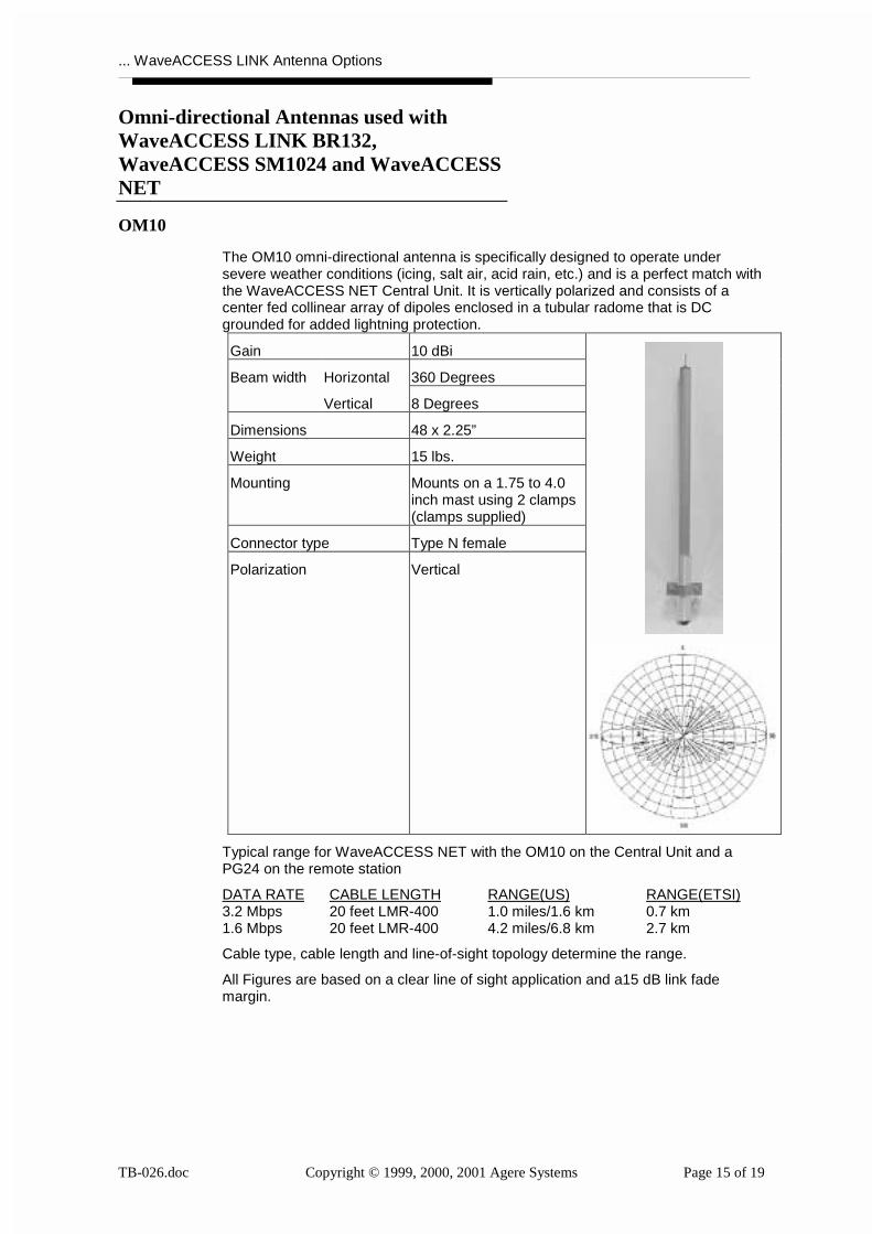
The OM10 omni-directional antenna is specifically designed to operate undersevere weather conditions (icing, salt air, acid rain, etc.) and is a perfect match withthe WaveACCESS NET Central Unit. It is vertically polarized and consists of acenter fed collinear array of dipoles enclosed in a tubular radome that is DCgrounded for added lightning protection.
Gain 10 dBi
Horizontal 360 DegreesBeam width
Vertical 8 Degrees
Dimensions 48 x 2.25”
Weight 15 lbs.
Mounting Mounts on a 1.75 to 4.0inch mast using 2 clamps(clamps supplied)
Connector type Type N female
Polarization Vertical
Typical range for WaveACCESS NET with the OM10 on the Central Unit and aPG24 on the remote station
DATA RATE CABLE LENGTH RANGE(US) RANGE(ETSI)3.2 Mbps 20 feet LMR-400 1.0 miles/1.6 km 0.7 km1.6 Mbps 20 feet LMR-400 4.2 miles/6.8 km 2.7 km
Cable type, cable length and line-of-sight topology determine the range.
All Figures are based on a clear line of sight application and a15 dB link fademargin.
... WaveACCESS LINK Antenna Options
TB-026.doc Copyright © 1999, 2000, 2001 Agere Systems Page 16 of 19
OM08
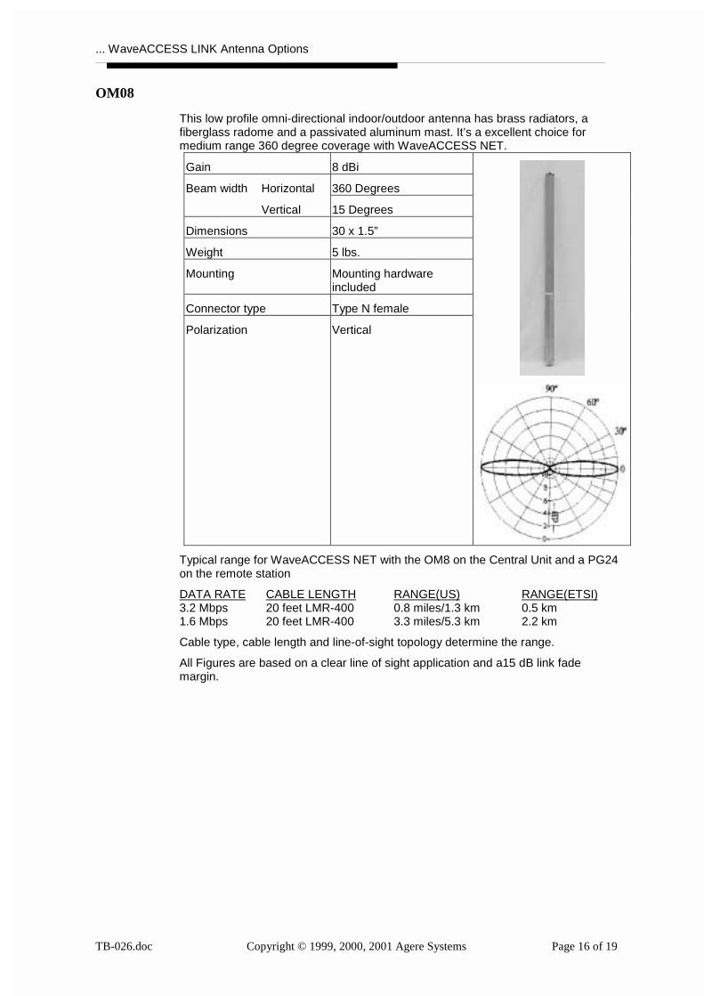
This low profile omni-directional indoor/outdoor antenna has brass radiators, afiberglass radome and a passivated aluminum mast. It’s a excellent choice formedium range 360 degree coverage with WaveACCESS NET.
Gain 8 dBi
Horizontal 360 DegreesBeam width
Vertical 15 Degrees
Dimensions 30 x 1.5”
Weight 5 lbs.
Mounting Mounting hardwareincluded
Connector type Type N female
Polarization Vertical
Typical range for WaveACCESS NET with the OM8 on the Central Unit and a PG24on the remote station
DATA RATE CABLE LENGTH RANGE(US) RANGE(ETSI)3.2 Mbps 20 feet LMR-400 0.8 miles/1.3 km 0.5 km1.6 Mbps 20 feet LMR-400 3.3 miles/5.3 km 2.2 km
Cable type, cable length and line-of-sight topology determine the range.
All Figures are based on a clear line of sight application and a15 dB link fademargin.
... WaveACCESS LINK Antenna Options
TB-026.doc Copyright © 1999, 2000, 2001 Agere Systems Page 17 of 19
OM05
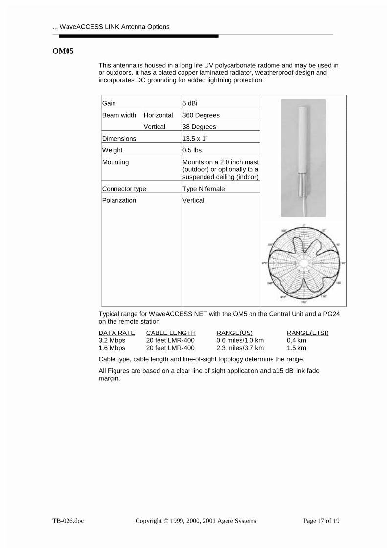
This antenna is housed in a long life UV polycarbonate radome and may be used inor outdoors. It has a plated copper laminated radiator, weatherproof design andincorporates DC grounding for added lightning protection.
Gain 5 dBi
Horizontal 360 DegreesBeam width
Vertical 38 Degrees
Dimensions 13.5 x 1”
Weight 0.5 lbs.
Mounting Mounts on a 2.0 inch mast(outdoor) or optionally to asuspended ceiling (indoor)
Connector type Type N female
Polarization Vertical
Typical range for WaveACCESS NET with the OM5 on the Central Unit and a PG24on the remote station
DATA RATE CABLE LENGTH RANGE(US) RANGE(ETSI)3.2 Mbps 20 feet LMR-400 0.6 miles/1.0 km 0.4 km1.6 Mbps 20 feet LMR-400 2.3 miles/3.7 km 1.5 km
Cable type, cable length and line-of-sight topology determine the range.
All Figures are based on a clear line of sight application and a15 dB link fademargin.
... WaveACCESS LINK Antenna Options
TB-026.doc Copyright © 1999, 2000, 2001 Agere Systems Page 18 of 19
Cable options used with WaveACCESSLINK BR132, WaveACCESS SM1024 andWaveACCESS NET
Part Cable AttenuationCoefficient
MinimumLength
Number Type [dB/100 ft] Ft.
LMR-400 Flex. 0.4" 6.7 20
LMR-600 Flex. 0.6" 4.4 30
LMR-900 Flex. 0.9" 2.9 45
LMR-1200 Flex. 1.2" 2.2 60
LMR-1700 Flex. 1.7" 1.7 80
LDF4-50A Heliax 0.63" 3.9 35
LDF5-50A Heliax 1.1" 2.2 60
LDF6-50 Heliax 1.55" 1.6 85
Other options used with WaveACCESSLINK BR132, WaveACCESS SM1024 andWaveACCESS NET
Item Description
Transition Cable 2’ length; reversed polarity SMA Female & Type NFemale
Lightning Arrestor Available for Standard-N and Reverse Polarity-Nsystems
Power Supply 110/220 - 6.2 V Power Supply
Standard Antenna 2 dBi Antenna; set of 2
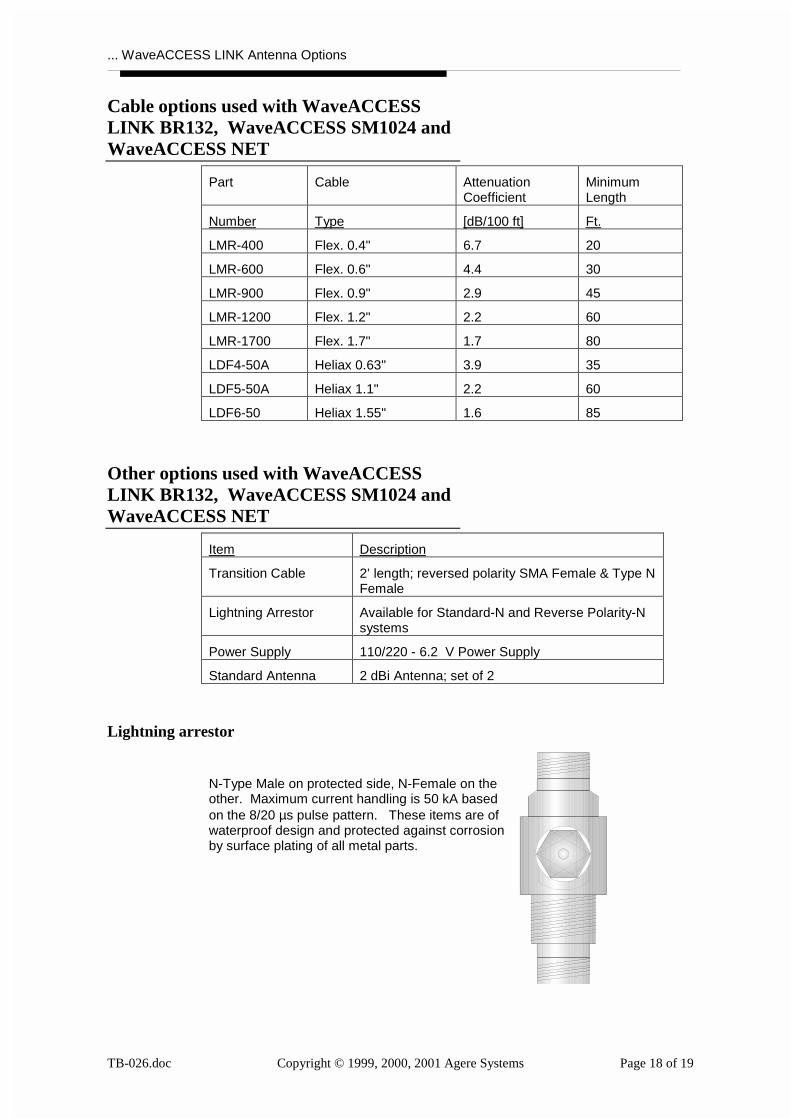
Lightning arrestor
N-Type Male on protected side, N-Female on theother. Maximum current handling is 50 kA basedon the 8/20 µs pulse pattern. These items are ofwaterproof design and protected against corrosionby surface plating of all metal parts.
... WaveACCESS LINK Antenna Options
TB-026.doc Copyright © 1999, 2000, 2001 Agere Systems Page 19 of 19
Previously Marketed Products
Following products were previously marketed either by WaveACCESS or by LucentTechnologies. These products are no longer orderable parts, but are for yourreference whenever you encounter these antennas on a technical support request.
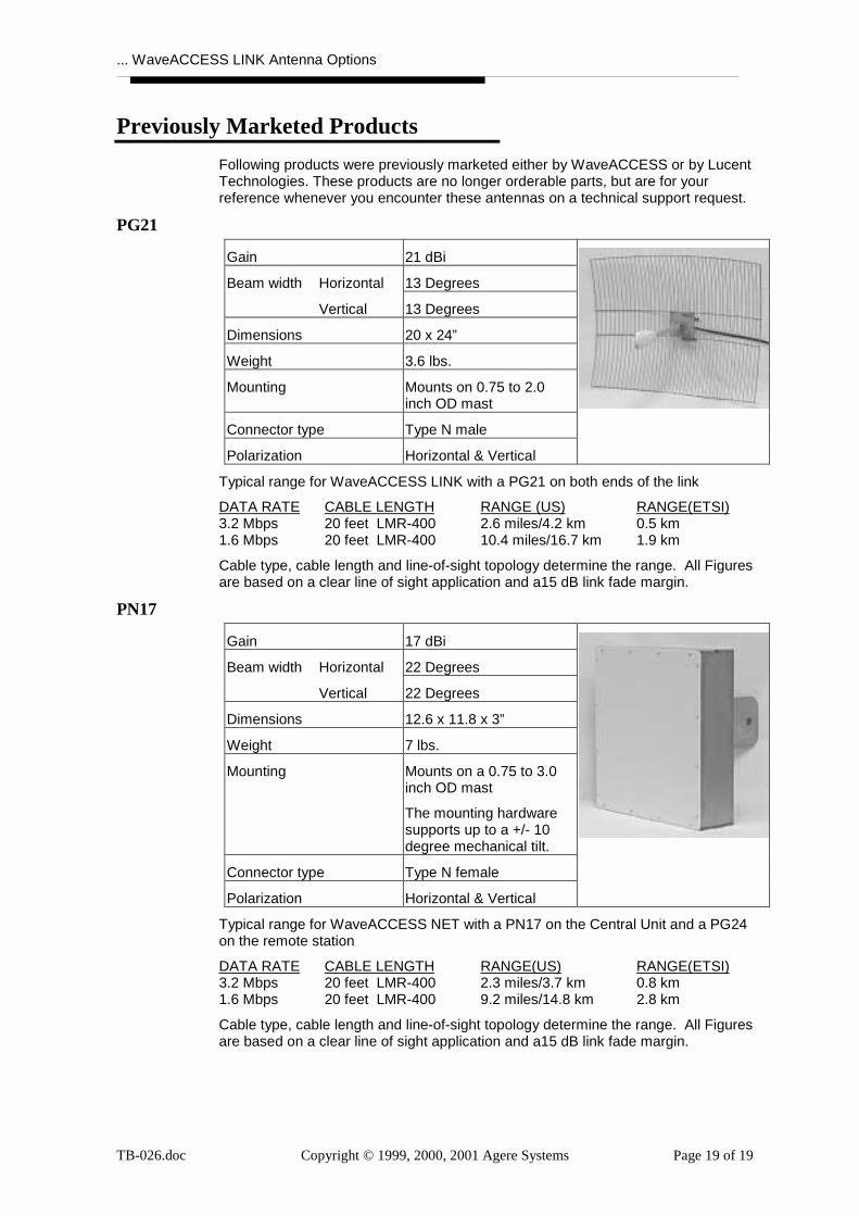
PG21
Gain 21 dBi
Horizontal 13 DegreesBeam width
Vertical 13 Degrees
Dimensions 20 x 24”
Weight 3.6 lbs.
Mounting Mounts on 0.75 to 2.0inch OD mast
Connector type Type N male
Polarization Horizontal & Vertical
Typical range for WaveACCESS LINK with a PG21 on both ends of the link
DATA RATE CABLE LENGTH RANGE (US) RANGE(ETSI)3.2 Mbps 20 feet LMR-400 2.6 miles/4.2 km 0.5 km1.6 Mbps 20 feet LMR-400 10.4 miles/16.7 km 1.9 km
Cable type, cable length and line-of-sight topology determine the range. All Figuresare based on a clear line of sight application and a15 dB link fade margin.
PN17
Gain 17 dBi
Horizontal 22 DegreesBeam width
Vertical 22 Degrees
Dimensions 12.6 x 11.8 x 3”
Weight 7 lbs.
Mounting Mounts on a 0.75 to 3.0inch OD mast
The mounting hardwaresupports up to a +/- 10degree mechanical tilt.
Connector type Type N female
Polarization Horizontal & Vertical
Typical range for WaveACCESS NET with a PN17 on the Central Unit and a PG24on the remote station
DATA RATE CABLE LENGTH RANGE(US) RANGE(ETSI)3.2 Mbps 20 feet LMR-400 2.3 miles/3.7 km 0.8 km1.6 Mbps 20 feet LMR-400 9.2 miles/14.8 km 2.8 km
Cable type, cable length and line-of-sight topology determine the range. All Figuresare based on a clear line of sight application and a15 dB link fade margin.