Embed Size (px)
Citation preview
MMOODDEELLSS 770000,, 990000,, AANNDD 995500 OOWWNNEERR’’SS MMAANNUUAALL AANNDD IINNSSTTAALLLLAATTIIOONN GGUUIIDDEE
VVEERRSSIIOONN 77..22
10 Year Limited Warranty To Whom Warranty Is Extended
This warranty is issued to the original owner at the original location site and is not transferable to other sites or to subsequent owners of the system.
TO PLACE THE EQUIPMENT UNDER WARRANTY, THE WARRANTY REGISTRATION CARD MUST BE COMPLETED AND RETURNED BY THE ORIGINAL OWNER TO WaterBoss® WITHIN 30 DAYS OF INSTALLATION.
Coverage
This limited warranty covers the WaterBoss® system delivered to the original owner at the original location when the system is purchased for personal, family, or household use. It is intended to cover defects occurring in workmanship or materials or both.
Warrantor’s Performance and Length of Limited Warranty
WaterBoss® warrants that upon receipt from the original owner of any mechanical or electronic part which is found to be defective in materials or workmanship, WaterBoss® will repair or replace the defective item for 3 years from date of original installation. Media is not warranted.
WaterBoss® further warrants that upon receipt from the original owner of any WaterBoss® media tank/valve body, brine cabinet, found to be defective in material or workmanship, WaterBoss® will repair or replace the defective item for 10 years from date of original installation.
All defective parts must be returned, along with the equipment serial number and date of original installation, to WaterBoss® PREPAID, and replacement parts will be returned by WaterBoss® to the original owner FREIGHT COLLECT.
Further Exclusions and Limitations on Warranty
THERE ARE NO WARRANTIES OTHER THAN THOSE DESCRIBED IN THIS WARRANTY INSTRUMENT.
This warranty does not cover any service call or labor costs incurred with respect to the removal and replacement of any defective part or parts. WaterBoss® will not be liable for, nor will it pay service call or labor charges incurred or expended with respect to this warranty.
In the event the water supply being processed through this product contains sand, bacterial iron, algae, sulphur, tannins, organic matter, or other unusual substances, then, unless the system is represented as being capable of handling these substances in the system specifications, other special treatment of the water supply must be used to remove these substances before they enter this product. Otherwise, WaterBoss® shall have no obligations under this warranty.
This warranty does not cover damage to a part or parts of the system from causes such as fire, accidents, freezing, or unreasonable use, abuse, or neglect by the owner.
This warranty does not cover damage to a part or parts of the system resulting from improper installation. All plumbing and electrical connections should be made in accordance with all local codes and the installation instructions provided with the system. The warranty does not cover damage resulting from use with inadequate or defective plumbing; inadequate or defective water supply or pressure; inadequate or defective house wiring; improper voltage, electrical service, or electrical connections; or violation of applicable building, plumbing, or electrical codes laws, ordinances, or regulations.
THIS WARRANTY DOES NOT COVER INCIDENTAL, CONSEQUENTIAL, OR SECONDARY DAMAGES.
ANY IMPLIED WARRANTIES ON THE PRODUCT DESCRIBED IN THIS WARRANTY WILL NOT BE EFFECTIVE AFTER THE EXPIRATION OF THIS WARRANTY.
No dealer, agent, representative or other person is authorized to extend or expand this limited warranty.
Some states do not allow limitations on how long an implied warranty lasts or the exclusion or limitation of incidental or consequential damages, so the above limitations and exclusion may not apply to you. This warranty gives you specific legal rights and you may also have other rights which vary from state to state.
Claims Procedures
Any defects covered by this warranty should be promptly reported to:
WaterBoss®
4343 South Hamilton Road Groveport, Ohio 43125
When writing about the defects, please provide the original owner’s name, telephone number, and original address, serial number and model number of the product, and date of purchase. (This information should be listed in General Information at the front of this manual.) WaterBoss® reserves the right to replace defective parts with exact duplicates or their equivalent.
Call the HelpLine, 1-800-437-8993, for Return Information from 8 a.m. to 5 p.m. EST. The HelpLine fax number is (614) 836-9876.
WaterBoss Owner’s Manual 9/2/2009 2
Contents General Information .......................................................................................................................................4 Getting Maximum Efficiency From the Appliance...........................................................................................5 Efficiency Statements.....................................................................................................................................5 Checklist Before Installation...........................................................................................................................6 Precautions ....................................................................................................................................................7 Installation Steps and Start-Up Procedures ...................................................................................................8 Bypass Valve ...............................................................................................................................................13 Four-Button Controller..................................................................................................................................14 Setting the Controller ...................................................................................................................................16 Advanced Customer Settings.......................................................................................................................17 Optional Plumbing Procedures.....................................................................................................................19 Assembly and Parts .....................................................................................................................................21 Troubleshooting ...........................................................................................................................................31 WaterBoss® Water Conditioner Specifications .............................................................................................33 Certificates ...................................................................................................................................................34
WaterBoss Owner’s Manual 9/2/2009 3
WaterBoss Owner’s Manual 9/2/2009 4
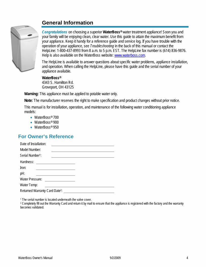
General Information Congratulations on choosing a superior WaterBoss® water treatment appliance! Soon you and your family will be enjoying clean, clear water. Use this guide to attain the maximum benefit from your appliance. Keep it handy for a reference guide and service log. If you have trouble with the operation of your appliance, see Troubleshooting in the back of this manual or contact the HelpLine: 1-800-437-8993 from 8 a.m. to 5 p.m. EST. The HelpLine fax number is (614) 836-9876. Help is also available on the WaterBoss website: www.waterboss.com. The HelpLine is available to answer questions about specific water problems, appliance installation, and operation. When calling the HelpLine, please have this guide and the serial number of your appliance available. WaterBoss® 4343 S. Hamilton Rd. Groveport, OH 43125
Warning: This appliance must be applied to potable water only. Note: The manufacturer reserves the right to make specification and product changes without prior notice. This manual is for installation, operation, and maintenance of the following water conditioning appliance models:
• WaterBoss® 700 • WaterBoss® 900 • WaterBoss® 950
For Owner’s Reference Date of Installation: Model Number: Serial Number1: Hardness: Iron: pH: Water Pressure: Water Temp: Returned Warranty Card Date2:
1 The serial number is located underneath the valve cover. 2 Completely fill out the Warranty Card and return it by mail to ensure that the appliance is registered with the factory and the warranty becomes validated.
WaterBoss Owner’s Manual 9/2/2009 5
Getting Maximum Efficiency From the Appliance To achieve the maximum benefit and performance from this appliance, familiarize yourself with this manual and the appliance. 1. The salt level should always be at least 1/3 full.
Refill the salt when the level drops below the water level in the brine cabinet. A resin cleaner can be used on a monthly basis. A clean pellet, solar, or cube-type salt is recommended. Do not use rock salt. Caution: Do not mix different types of salt.
2. You may switch to a salt substitute (such as potassium chloride) in place of water conditioner salt at any time. If potassium chloride is used in place of salt, increase your hardness setting by 12% (multiply by 1.12). See Setting the Controller. Caution: Do not use potassium chloride if there is iron and/or manganese in the water.
3. Should your electricity be off for any reason check your controller for the correct time and reset as necessary (See Advanced Customer Settings).
4. Program the appliance to regenerate at a time when the water is not being used. If there is more than one appliance, allow two hours between each regeneration.
5. If dirt, sand, or large particles are present in the water supply, the appropriate WaterBoss® filter can eliminate this problem.
6. The appliance may be disinfected with 5.25% sodium hypochlorite, which is the active ingredient in household chlorine bleach. To disinfect the appliance, add 4.0 fluid ounces of chlorine bleach solution to the brine well of the brine cabinet. The brine cabinet should have water in it. Start a manual regeneration.
7. Protect the appliance, including the drain line, from freezing.
8. The bypass valve (located on the main control valve) enables you to bypass the appliance if any work is being performed on the appliance, well pump, or plumbing. See Bypass Valve. Use Bypass mode also for watering plants or lawns with untreated water.
9. Before putting the appliance back in service after work has been performed, turn on the nearest cold water tap until water runs clear.
10. Adhere to all operational, maintenance, and placement requirements.
11. Inspect and clean the brine cabinet and air check/draw tube assembly annually or when sediment is present in the brine cabinet.
12. Potassium permanganate will need to be added periodically to any iron filter.
13. Model 950 contains redox media and activated carbon media. These have a finite life and will eventually require replacement if the advertised performance capabilities of this device are to be maintained.
14. This product is certified for barium and radium 226/228 reduction according to NSF/ANSI Standard 44. Any Bypass system must be completely in the Service position to ensure maximum barium and radium 226/228 reduction.
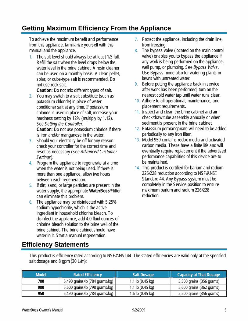
Efficiency Statements This product is efficiency rated according to NSF/ANSI 44. The stated efficiencies are valid only at the specified salt dosage and 8 gpm (30 L/m):
Model Rated Efficiency Salt Dosage Capacity at That Dosage 700 5,490 grains/lb (784 grams/kg) 1.1 lb (0.45 kg) 5,500 grains (356 grams) 900 5,600 grains/lb (798 grams/kg) 1.1 lb (0.45 kg) 5,600 grains (362 grams) 950 5,490 grains/lb (784 grams/kg) 1.6 lb (0.45 kg) 5,500 grains (356 grams)
WaterBoss Owner’s Manual 9/2/2009 6
Checklist Before Installation Refer to this checklist before installation.
Water Quality—If the water supply contains sand, sulfur, bacteria, iron bacteria, tannins, algae, oil, acid, or other unusual substances, consider pre-treating the water to remove these contaminants before the water supply enters the appliance, unless the appliance is represented as being capable of treating these contaminants in its specifications. The appropriate WaterBoss® Water Filter can address these water shortcomings. Model 900-IF (Iron Filter)–Reduces iron, manganese, hydrogen sulfide, and iron bacteria. Model 900-NF (Acid Neutralizing filter)–Adjusts low pH water to a non-corrosive state.
Iron—A common problem found in many water supplies is iron. It is important to know what type of and how much iron is in the water supply.
Iron Type Description Ferrous Iron* (sometimes called clear water or dissolved iron)
Only type of iron that can be treated with a water softener
Ferric Iron Insoluble and the particles can eventually foul a resin bed. It should be filtered out before the water reaches the softener
Organic Iron or Bacterial Iron
Attached to other organic compounds in the water. Additional treatment is needed to remove this type of iron
Colloidal Iron Not dissolved, yet stays in suspension. A softener cannot remove this type of iron * If the water supply contains ferrous iron, a commercially available resin bed cleaner should be used every six months. Follow the instructions on the container. You should also increase your water hardness setting by 5 grains per gallon (86 mg/L) for every 1 ppm (1 mg/L) of ferrous iron.
Water Characteristics—Models 700, 900, and 950 require a pH of 7 or above to function properly. An iron test to determine iron levels is also necessary. The 900-NF Acid Neutralizing Filter adjusts pH levels of 6.3 or above.
Water Hardness—Double check hardness of water with test strips provided to verify that your appliance is right for the job. Model 950 are FOR MUNICIPALLY-SUPPLIED WATER without iron. Model 950 will condition water up to 35 grains of hardness per gallon (599 mg/L). Model 700 will condition water for up to 70 grains of hardness per gallon (1,197 mg/L). Model 900 will condition water for up to 90 grains of hardness per gallon (1,539 mg/L). (See Specifications.)
Water Pressure—Not less than 20 psi or greater than 120 psi (1.4–8.4 bar) constant. If water pressure exceeds 70 psi (4.8 bar), a pressure regulator is recommended.
Water Supply Flow Rate—A minimum of 2.4 gallons (9 L) for the 700 and 900 models to 3 gallons (11.4 L) for the 950 model per minute or equal to the backwash flow rate of the particular model is recommended. For the purposes of plumbing sizing, only the rated service flow rate and corresponding pressure loss may be used. Prolonged operation of a water conditioner at flow rates exceeding the tested service flow rate may compromise performance.
WaterBoss Owner’s Manual 9/2/2009 7
Checklist Before Installation, Cont. Water Temperature—Not less than 40° or greater than 120°F (6°–49°C). Drain—Drain the appliance to an appropriate drain, such as a floor drain or washer drain that will comply with
all local and state plumbing codes. To prevent back-siphoning, provide an adequate air gap or a siphon break. See Installation Steps and Start-Up Procedures.
Electricity—The transformer supplied is for a standard 115 volt, 60-cycle AC outlet for locations in North America or 220 volt, 50-cycle AC outlet for locations outside North America. If you have any questions, call the HelpLine. See General Information at the front of the manual for information about the HelpLine.
Precautions
Do 1. Comply with all state and local, building, plumbing, and electrical codes. 2. Test your water quality with the strips provided. Optionally, obtain a report on your water’s quality. 3. Install the appliance before the water heater. 4. Install the appliance after the pressure tank on well-water installations. 5. Examine the inlet line from the pressure tank to appliance on well water with iron (recommended minimum
inlet pipe size 3/4-inch I.D.). On municipal water, recommended minimum inlet pipe size is 1/2-inch I.D. 6. Install a pressure-reducing valve if the inlet pressure exceeds 70 psi (4.8 bar). 7. Install a gravity drain on the cabinet. 8. Secure the drain line on the appliance and at the drain outlet. See Installation Steps and Start-Up
Procedures. 9. Allow a minimum of 8 to 10 feet (2.4 to 3.0 m) of 3/4-inch pipe from the outlet of the appliance to the inlet of
the water heater.
Do Not 1. Do not install if checklist items are not satisfactory. See Checklist Before Installation. 2. Do not install if the incoming or outlet piping water temperature exceeds 120°F (49°C). See Specifications. 3. Do not allow soldering torch heat to be transferred to valve components or plastic parts when using the
optional copper adapters. 4. Do not overtighten the plastic fittings. 5. Do not plumb the appliance against a wall that would prohibit access to plumbing. See Installation Steps
and Start-Up Procedures. 6. Do not install the appliance backward. Follow the arrows on the inlet and outlet. 7. Do not plug the transformer into an outlet that is activated by an On/Off switch. 8. Do not connect the drain and the overflow (gravity drain) lines together. 9. Do not use to treat water that is microbiologically unsafe or of unknown quality without adequate
disinfection before or after the appliance. 10. Do not allow your appliance or drain line to freeze.
WaterBoss Owner’s Manual 9/2/2009 8
Installation Steps and Start-Up Procedures The water softener is capable of treating a combination of undesirable constituents (such as iron, dirt, sediment, chlorine, and/or lead) in water. See Specifications for the capabilities of your appliance. Install, set up, and use the appliance within the operating limits outlined in this manual. Failure to comply with these specifications may decrease the effectiveness of the backwash and cause control valve malfunction. The water softener, like any other appliance, requires correct installation and setting for optimum performance. Each water treatment appliance includes water test strips, eight feet of drain line, and a drain fitting.
Step 1 Prepare the Placement Area A. Make sure the placement area is clean. B. Turn off the electricity and water supply to the water heater. For gas water heaters, turn the
gas cock to “Pilot.” C. Examine the inlet plumbing to ensure that the pipe is not plugged with lime, iron, or any
other substance. Clean or replace plugged plumbing. Note: A minimum 3/4-inch pipe is required between the pressure tank and the appliance for the appliance to function properly.
D. Make sure the inlet/outlet and drain connections meet the applicable state and local codes. E. Check the arrows on the bypass valve to ensure that the water flows in the proper direction.
See Bypass Valve. Caution: Do not plumb the appliance in backward.
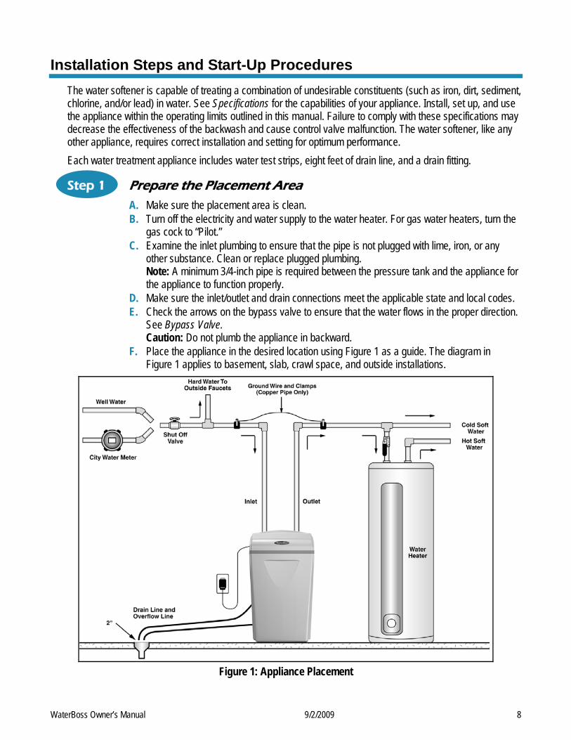
F. Place the appliance in the desired location using Figure 1 as a guide. The diagram in Figure 1 applies to basement, slab, crawl space, and outside installations.
Figure 1: Appliance Placement
WaterBoss Owner’s Manual 9/2/2009 9
Installation Steps and Start-Up Procedures, Cont. G. For most installations, install the appliance after the pressure tank and any water filter
appliance or water meter and before the water heater unless otherwise recommended. When installing a carbon filter for well water, place the filter after any water conditioning appliance unless otherwise recommended. Contact the HelpLine for further assistance in determining the proper installation sequence. Water Heaters: If less than 10 feet (3.0 m) of pipe connects the water treatment appliance(s) to the water heater, install a check valve between the water treatment appliance and the water heater as close to the water heater as possible. Ensure that the water heater has an adequately rated temperature and pressure safety relief valve.
H. For outside installations, the appliance should be enclosed so it is protected from the weather.
Step 2 Test Your Water A. Remove any packaging or installation materials from the brine cabinet. B. Test your water quality with the strips provided. (See Setting the Controller) Optionally, obtain
a report on your water’s quality.
Step 3 Turn Off Water Supply A. Turn off the water supply. B. Open the hot and cold water taps to depressurize the lines.
Step 4 Connect Water Lines
Note: See Optional Plumbing Procedures for information on copper fittings and joining plastic pipe.
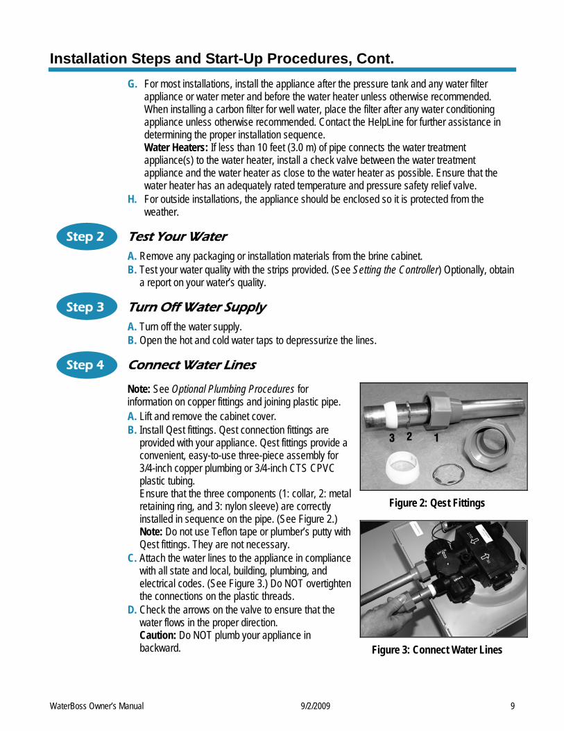
A. Lift and remove the cabinet cover. B. Install Qest fittings. Qest connection fittings are
provided with your appliance. Qest fittings provide a convenient, easy-to-use three-piece assembly for 3/4-inch copper plumbing or 3/4-inch CTS CPVC plastic tubing. Ensure that the three components (1: collar, 2: metal retaining ring, and 3: nylon sleeve) are correctly installed in sequence on the pipe. (See Figure 2.) Note: Do not use Teflon tape or plumber’s putty with Qest fittings. They are not necessary.
Figure 2: Qest Fittings
C. Attach the water lines to the appliance in compliance with all state and local, building, plumbing, and electrical codes. (See Figure 3.) Do NOT overtighten the connections on the plastic threads.
D. Check the arrows on the valve to ensure that the water flows in the proper direction. Caution: Do NOT plumb your appliance in backward. Figure 3: Connect Water Lines
WaterBoss Owner’s Manual 9/2/2009 10
Installation Steps and Start-Up Procedures, Cont.
Step 5 Connect Gravity Overflow Connection
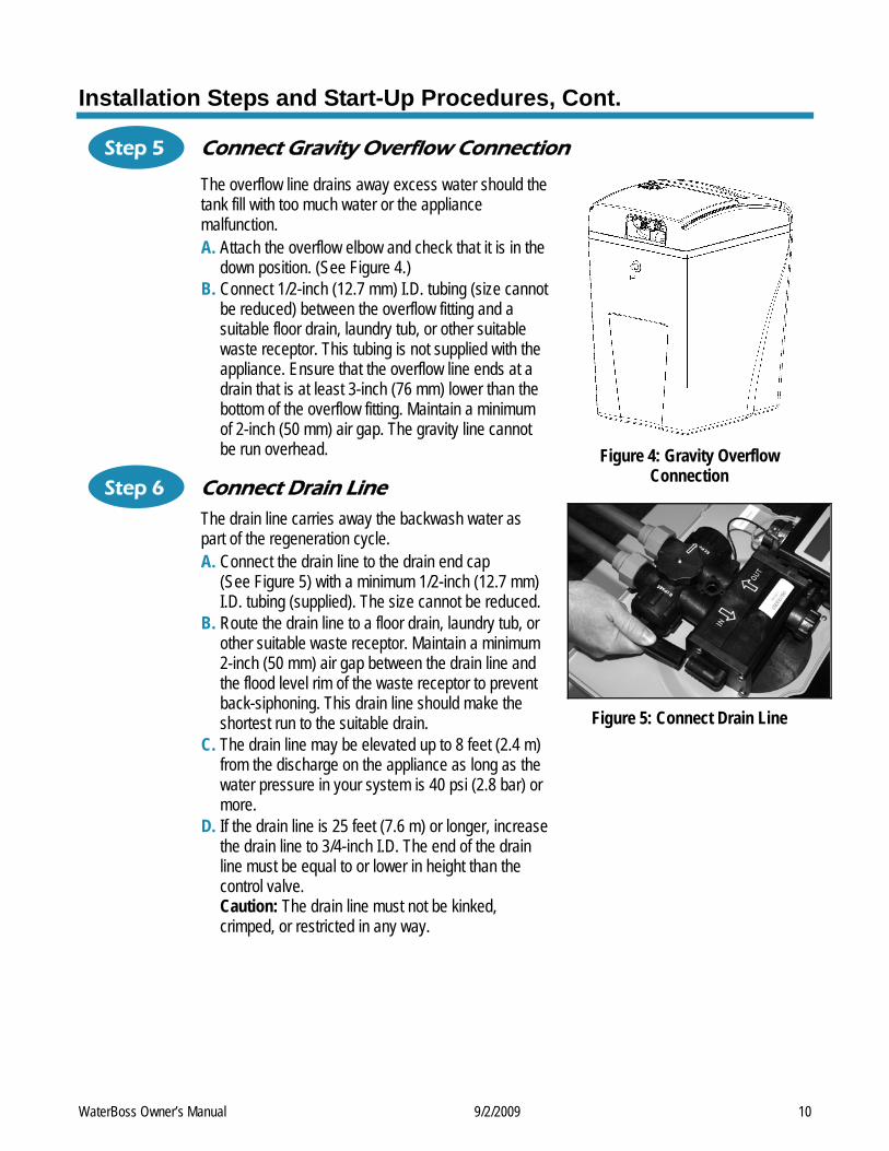
The overflow line drains away excess water should the tank fill with too much water or the appliance malfunction. A. Attach the overflow elbow and check that it is in the
down position. (See Figure 4.) B. Connect 1/2-inch (12.7 mm) I.D. tubing (size cannot
be reduced) between the overflow fitting and a suitable floor drain, laundry tub, or other suitable waste receptor. This tubing is not supplied with the appliance. Ensure that the overflow line ends at a drain that is at least 3-inch (76 mm) lower than the bottom of the overflow fitting. Maintain a minimum of 2-inch (50 mm) air gap. The gravity line cannot be run overhead.
Step 6 Connect Drain Line The drain line carries away the backwash water as part of the regeneration cycle. A. Connect the drain line to the drain end cap
(See Figure 5) with a minimum 1/2-inch (12.7 mm) I.D. tubing (supplied). The size cannot be reduced.
B. Route the drain line to a floor drain, laundry tub, or other suitable waste receptor. Maintain a minimum 2-inch (50 mm) air gap between the drain line and the flood level rim of the waste receptor to prevent back-siphoning. This drain line should make the shortest run to the suitable drain.
C. The drain line may be elevated up to 8 feet (2.4 m) from the discharge on the appliance as long as the water pressure in your system is 40 psi (2.8 bar) or more.
D. If the drain line is 25 feet (7.6 m) or longer, increase the drain line to 3/4-inch I.D. The end of the drain line must be equal to or lower in height than the control valve. Caution: The drain line must not be kinked, crimped, or restricted in any way.
Figure 4: Gravity Overflow
Connection
Figure 5: Connect Drain Line
WaterBoss Owner’s Manual 9/2/2009 11
Installation Steps and Start-Up Procedures, Cont.
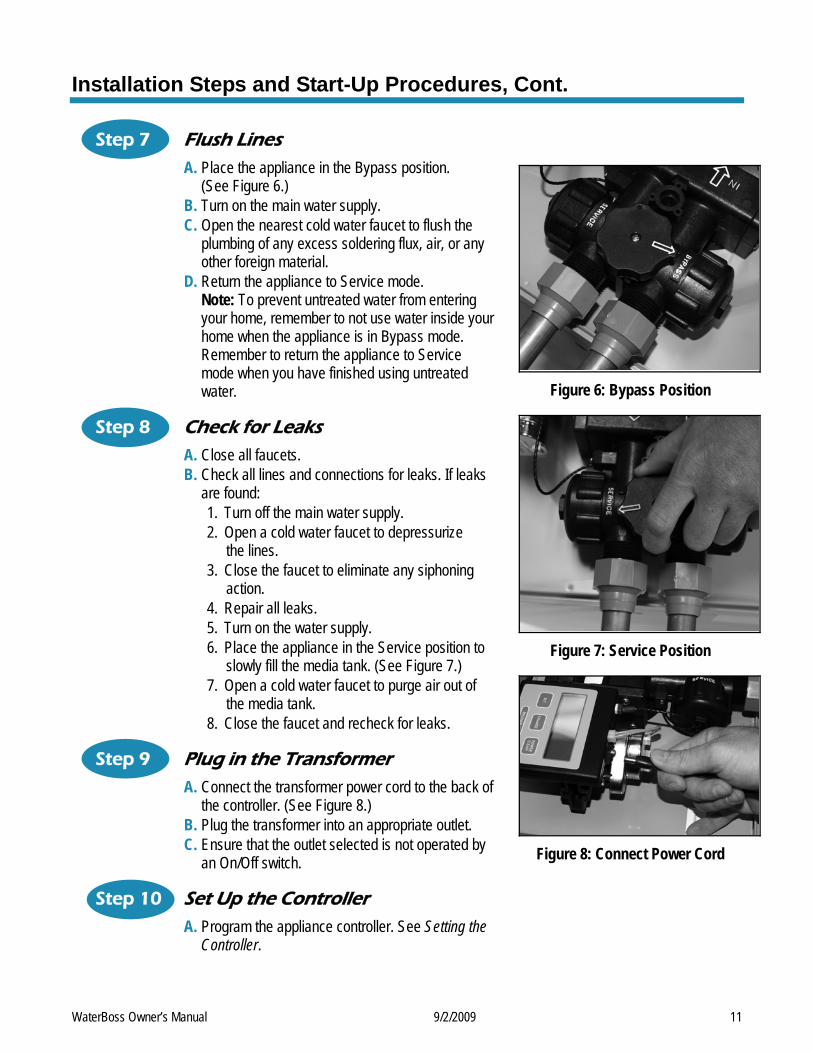
Step 7 Flush Lines A. Place the appliance in the Bypass position.
(See Figure 6.) B. Turn on the main water supply. C. Open the nearest cold water faucet to flush the
plumbing of any excess soldering flux, air, or any other foreign material.
D. Return the appliance to Service mode. Note: To prevent untreated water from entering your home, remember to not use water inside your home when the appliance is in Bypass mode. Remember to return the appliance to Service mode when you have finished using untreated water.
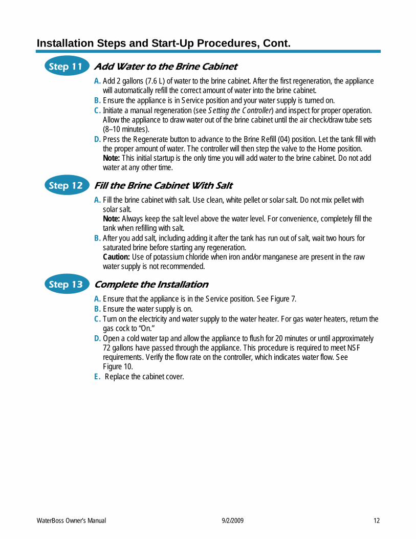
Step 8 Check for Leaks A. Close all faucets. B. Check all lines and connections for leaks. If leaks
are found: 1. Turn off the main water supply. 2. Open a cold water faucet to depressurize
the lines. 3. Close the faucet to eliminate any siphoning
action. 4. Repair all leaks. 5. Turn on the water supply. 6. Place the appliance in the Service position to
slowly fill the media tank. (See Figure 7.) 7. Open a cold water faucet to purge air out of
the media tank. 8. Close the faucet and recheck for leaks.
Step 9 Plug in the Transformer A. Connect the transformer power cord to the back of
the controller. (See Figure 8.) B. Plug the transformer into an appropriate outlet. C. Ensure that the outlet selected is not operated by
an On/Off switch.
Step 10 Set Up the Controller A. Program the appliance controller. See Setting the
Controller.
Figure 6: Bypass Position
Figure 7: Service Position
Figure 8: Connect Power Cord
WaterBoss Owner’s Manual 9/2/2009 12
Installation Steps and Start-Up Procedures, Cont.
Step 11 Add Water to the Brine Cabinet A. Add 2 gallons (7.6 L) of water to the brine cabinet. After the first regeneration, the appliance
will automatically refill the correct amount of water into the brine cabinet. B. Ensure the appliance is in Service position and your water supply is turned on. C. Initiate a manual regeneration (see Setting the Controller) and inspect for proper operation.
Allow the appliance to draw water out of the brine cabinet until the air check/draw tube sets (8–10 minutes).
D. Press the Regenerate button to advance to the Brine Refill (04) position. Let the tank fill with the proper amount of water. The controller will then step the valve to the Home position. Note: This initial startup is the only time you will add water to the brine cabinet. Do not add water at any other time.
Step 12 Fill the Brine Cabinet With Salt A. Fill the brine cabinet with salt. Use clean, white pellet or solar salt. Do not mix pellet with
solar salt. Note: Always keep the salt level above the water level. For convenience, completely fill the tank when refilling with salt.
B. After you add salt, including adding it after the tank has run out of salt, wait two hours for saturated brine before starting any regeneration. Caution: Use of potassium chloride when iron and/or manganese are present in the raw water supply is not recommended.
Step 13 Complete the Installation A. Ensure that the appliance is in the Service position. See Figure 7. B. Ensure the water supply is on. C. Turn on the electricity and water supply to the water heater. For gas water heaters, return the
gas cock to “On.” D. Open a cold water tap and allow the appliance to flush for 20 minutes or until approximately
72 gallons have passed through the appliance. This procedure is required to meet NSF requirements. Verify the flow rate on the controller, which indicates water flow. See Figure 10.
E. Replace the cabinet cover.
WaterBoss Owner’s Manual 9/2/2009 13
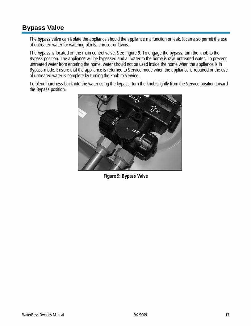
Bypass Valve The bypass valve can isolate the appliance should the appliance malfunction or leak. It can also permit the use of untreated water for watering plants, shrubs, or lawns. The bypass is located on the main control valve. See Figure 9. To engage the bypass, turn the knob to the Bypass position. The appliance will be bypassed and all water to the home is raw, untreated water. To prevent untreated water from entering the home, water should not be used inside the home when the appliance is in Bypass mode. Ensure that the appliance is returned to Service mode when the appliance is repaired or the use of untreated water is complete by turning the knob to Service. To blend hardness back into the water using the bypass, turn the knob slightly from the Service position toward the Bypass position.
Figure 9: Bypass Valve
WaterBoss Owner’s Manual 9/2/2009 14 14
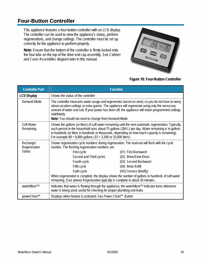
Four-Button Controller Four-Button Controller This appliance features a four-button controller with an LCD display. The controller can be used to view the appliance’s status, perform regenerations, and change settings. The controller must be set up correctly for the appliance to perform properly.
Note: Ensure that the bottom of the controller is firmly locked onto the four tabs on the top of the drive end cap assembly. See Cabinet and Cover Assemblies diagram later in this manual.
Figure 10: Four-Button Controller
Controller Part Function LCD Display Shows the status of the controller
Demand Mode The controller measures water usage and regenerates based on need, so you do not have to worry about vacation settings or extra guests. The appliance will regenerate using only the necessary amount of water and salt. If your power has been off, the appliance will retain programmed settings indefinitely Note: You should not need to change from Demand Mode
Soft Water Remaining
Shows the gallons (or liters) of soft water remaining until the next automatic regeneration. Typically, each person in the household uses about 75 gallons (284 L) per day. Water remaining is in gallons in hundreds (or liters in hundreds or thousands, depending on how much capacity is remaining). For example 88 = 8,800 gallons (33 = 3,300 or 33,000 liters)
Recharge/ Regeneration Status
Shows regeneration cycle numbers during regeneration. The read-out will flash with the cycle number. The flashing regeneration numbers are:
First cycle (01) First Backwash Second and Third cycles (02) Brine/Slow Rinse Fourth cycle (03) Second Backwash Fifth cycle (04) Brine Refill Sixth cycle (HO) Service (Briefly)
When regeneration is complete, the display shows the number of gallons in hundreds of soft water remaining. (See above) Regeneration typically is complete in about 30 minutes.
waterMizerTM Indicates that water is flowing through the appliance; the waterMizerTM indicator turns whenever water is being used; useful for checking for proper plumbing and leaks
powerClean™ Displays when feature is activated. See Power Clean™ Button
WaterBoss Owner’s Manual 9/2/2009 15
Four-Button Controller, Cont.
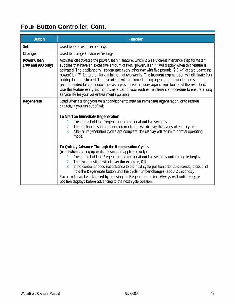
Button Function Set Used to set Customer Settings Change Used to change Customer Settings Power Clean (700 and 900 only)
Activates/deactivates the powerClean™ feature, which is a service/maintenance step for water supplies that have an excessive amount of iron. “powerClean™” will display when this feature is activated. The appliance will regenerate every other day with five pounds (2.3 kg) of salt. Leave the powerClean™ feature on for a minimum of two weeks. The frequent regeneration will eliminate iron buildup in the resin bed. The use of salt with an iron cleaning agent or iron out cleaner is recommended for continuous use as a preventive measure against iron fouling of the resin bed. Use this feature every six months as a part of your routine maintenance procedure to ensure a long service life for your water treatment appliance
Regenerate Used when starting your water conditioner to start an immediate regeneration, or to restore capacity if you run out of salt To Start an Immediate Regeneration
1. Press and hold the Regenerate button for about five seconds. 2. The appliance is in regeneration mode and will display the status of each cycle. 3. After all regeneration cycles are complete, the display will return to normal operating
mode. To Quickly Advance Through the Regeneration Cycles (used when starting up or diagnosing the appliance only)
1. Press and hold the Regenerate button for about five seconds until the cycle begins. 2. The cycle position will display (for example, 01). 3. If the controller does not advance to the next cycle position after 20 seconds, press and
hold the Regenerate button until the cycle number changes (about 2 seconds). Each cycle can be advanced by pressing the Regenerate button. Always wait until the cycle position displays before advancing to the next cycle position.
WaterBoss Owner’s Manual 9/2/2009 16
Setting the Controller
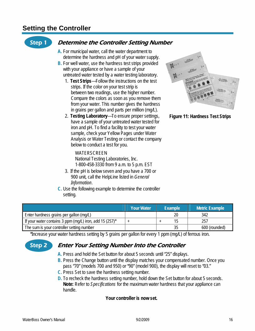
Step 1 Determine the Controller Setting Number A. For municipal water, call the water department to
determine the hardness and pH of your water supply. B. For well water, use the hardness test strips provided
with your appliance or have a sample of your untreated water tested by a water testing laboratory. 1. Test Strips—Follow the instructions on the test
strips. If the color on your test strip is between two readings, use the higher number. Compare the colors as soon as you remove them from your water. This number gives the hardness in grains per gallon and parts per million (mg/L).
2. Testing Laboratory—To ensure proper settings, have a sample of your untreated water tested for iron and pH. To find a facility to test your water sample, check your Yellow Pages under Water Analysis or Water Testing or contact the company below to conduct a test for you.
WATERSCREEN National Testing Laboratories, Inc. 1-800-458-3330 from 9 a.m. to 5 p.m. EST
3. If the pH is below seven and you have a 700 or 900 unit, call the HelpLine listed in General Information.
C. Use the following example to determine the controller setting.
Figure 11: Hardness Test Strips
Your Water Example Metric Example Enter hardness grains per gallon (mg/L) 20 342 If your water contains 3 ppm (mg/L) iron, add 15 (257)* + + 15 257 The sum is your controller setting number 35 600 (rounded)
*Increase your water hardness setting by 5 grains per gallon for every 1 ppm (mg/L) of ferrous iron.
Step 2 Enter Your Setting Number Into the Controller A. Press and hold the Set button for about 5 seconds until “25” displays. B. Press the Change button until the display matches your compensated number. Once you
pass “70” (models 700 and 950) or “90” (model 900), the display will reset to “03.” C. Press Set to save the hardness setting number. D. To recheck the hardness setting number, hold down the Set button for about 5 seconds.
Note: Refer to Specifications for the maximum water hardness that your appliance can handle.
Your controller is now set.
WaterBoss Owner’s Manual 9/2/2009 17
Advanced Customer Settings Most customers will want to use the factory default settings, so no changes are necessary. However, you can reset the controller settings if the factory default settings are not suitable for your needs. Note: Be sure to check that the Time of Day is correct.
Set High Capacity or High Efficiency Your appliance can be programmed for High Capacity (HC) or High Efficiency (HE).
• High Capacity means the appliance will regenerate less often, but use more salt. • High Efficiency will make the appliance regenerate more often and use less salt. This is the default. The
High Efficiency setting meets or exceeds the requirement some states have for salt efficiency. To Enter Advanced Customer Settings Mode
A. Press the Set and Change buttons for 3 seconds. The display should show only the controller type. After 3 seconds, the entire screen is lit for a half second, and then “HC” displays.
B. Press Change to toggle the digit display between “HC” and “HE.” C. When the desired value is displayed, press Set.
Note: HE ensures the appliance chooses salt settings that get 4,000 grains per pound (570 grams/kg) of salt for each regeneration or better. This choice meets or exceeds the requirement some states currently have in regards to salt efficiency.
Note: All models are equipped with patented capacity guard. Once in HC or HE, you can set the mode, hours to next generation, gallons or liters, time format, time of day, and time of regeneration.
Step 1 Set Mode Display reads “Demand Mode.” To Change Mode A. Press Change.
− Delay Mode allows regeneration at a specific time (for example, at 2 a.m. when less water is typically being used).
− Demand Mode triggers a regeneration as soon as softening capacity is exhausted. This is the default.
B. When the desired mode is displayed, press Set.
Step 2 Set Hours Until Regeneration Display reads “96 Hours.” To Change Setting A. Press Change to turn Off. If “96 Hours” is selected, the appliance will work no more than 4
days without a regeneration. Default is for “96 Hours” to be On. Note: If there is iron in your water, select this option. If you are using model 950, on most municipal water supplies, turn this option Off.
B. When the desired setting is displayed, press Set.
WaterBoss Owner’s Manual 9/2/2009 18
Advanced Customer Settings, Cont.
Step 3 Set Gallons or Liters Display reads “Gallons (or Liters) x 100.” To Set Gallons or Liters A. Press Change to toggle between gallons and liters. Choosing “Gallons” sets the controller to
English units, and choosing “Liters” sets it to metric units. B. When the desired units are displayed, press Set.
Step 4 Set Time Format Display reads “12” if gallons were chosen or “24” if liters were chosen. To Set Time Format A. Press Change to toggle between 24 and 12. This controls the selection of a 12-hour (AM/PM)
or 24-hour clock. If 24-hour, 00=midnight. B. When the desired time format is displayed, press Set.
Step 5 Set Time of Day Display reads “Set Time” and “12” (or “24”). To Change Time of Day A. Press Change until the current time is displayed. Default is 12 PM.
Note: Set time to the nearest hour. B. When the desired time is displayed, press Set.
Step 6 Set Regeneration Time Display reads “Set Reg. Time” followed by the current regeneration time that is set (02). To Change Regeneration Time A. Press Change. Default is 2 AM. B. When the desired regeneration time is displayed, press Set. Note: Whenever you experience an electrical outage, check your controller for the correct time. Make any necessary corrections.
Programming is now complete.
WaterBoss Owner’s Manual 9/2/2009 19
Optional Plumbing Procedures This section provides information on plumbing with copper fittings and with plastic pipe.
Hard Plumbing the Bypass With Copper Fittings Do not use Qest fittings for hard plumbing with copper fittings. When preparing the male threaded fittings of the I/O adapter, use the following guidelines to avoid damage to the plastic pipe threads.
A. Wrap the threads three times with 1/2-in. wide Teflon tape. Place each consecutive wrap on top of the previous wrap.
B. To prevent tearing of the tape, use Teflon paste on the first two male threads only. The paste lubricates the tape and fills the small void areas that might exist between the threads. When the joint is complete, there will be a small bead of sealant at the fitting interface, which indicates a properly joined connection.
C. Use a union with a threaded connection to facilitate repair of potential leaks in soldered joints. D. Prepare the copper tail assemblies in advance to enable them to cool prior to final assembly. Advance
preparation and cooling will prevent heat damage to the plastic pipe threads of the adapter. E. Ensure that the copper tube is at least 10 cm (4 in.) long. F. Turn the fitting counterclockwise until you feel the threads engage and then tighten to prevent cross
threading. Do NOT overtighten the fittings. Caution: Do NOT allow heat from the torch to transfer to the plastic valve component, which could be damaged.
WaterBoss Owner’s Manual 9/2/2009 20
Optional Plumbing Procedures, Cont.
Plastic (PVC/CPVC) Pipe Joining Procedures To ensure reliable joint integrity when using solvent cement for PVC/CPVC plumbing, follow these recommendations:
A. Cutting—The pipe must be cut square to allow for the proper interfacing of the pipe end and the fitting socket bottom. Use a wheel cutter, miter saw, or a ratchet shear for best results.
B. Deburring and Beveling—Use a knife, plastic pipe deburring tool, or a file to remove burrs from the end of the pipe. Be sure to remove all burrs from the inside as well as the outside of the pipe. All pipe ends should be beveled to permit easier insertion of the pipe into the fitting. Failure to bevel the pipe end may cause a “wiping” effect in the fitting where the cement is forced to the end of the fitting socket. This creates a weak joint.
C. Test Dry Fit of the Joint—Tapered fitting sockets are designed so that an interference fit should occur when the pipe is inserted about one-third to two-thirds of the way into the socket. Occasionally, when pipe and fitting dimensions are at the tolerance extremes, it will be possible to fully insert dry pipe to the bottom of the fitting socket. When this happens, a sufficient quantity of cement must be applied to the joint to fill the gap between the pipe and fitting.
D. Inspection, Cleaning, and Priming—Inspect the inside of the pipe and fitting sockets and remove dirt, grease, or moisture with a clean dry cloth. If wiping fails to clean the surfaces, use a chemical cleaner. Check for possible damage such as splits or cracks and replace if necessary. Use purple primer to penetrate and soften the bonding surfaces of the PVC or CPVC pipe and fittings. Proceed without hesitation to the cementing procedure while the primed surfaces are still wet.
E. Application of Solvent Cement—Apply the solvent cement evenly and quickly around the outside of the pipe while the primer is still wet. Apply a light coat of cement evenly around the inside of the fitting socket. Do not allow excess cement to “puddle” in the fitting. Apply a second coat of cement to the pipe end.
F. Joint Assembly—Working quickly, insert the pipe into the fitting socket and give a one-quarter turn of the pipe or fitting while pushing toward the fitting stop. This action will evenly distribute the cement. Do NOT continue to rotate the pipe or fitting after the stop has been reached. Hold the joint tightly together for about 15 seconds to prevent the pipe from “creeping” out of the fitting. A good joint will have sufficient cement to make a small bead all the way around the outside of the fitting hub. The joint should not be disturbed immediately after the cementing procedure. Allow adequate time for the joint to cure properly. Exact drying time is hard to predict because of environmental variables. Follow the recommended joint curing times on the primer and cement container labels.
WaterBoss Owner’s Manual 9/2/2009 21
Assembly and Parts
Cabinet/Cover/Salt Lid Assemblies
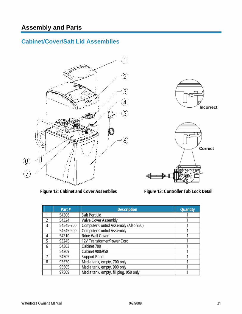
Figure 12: Cabinet and Cover Assemblies Figure 13: Controller Tab Lock Detail
Part # Description Quantity 1 54306 Salt Port Lid 1 2 54324 Valve Cover Assembly 1 3 54545-700 Computer Control Assembly (Also 950) 1 54545-900 Computer Control Assembly 1 4 54310 Brine Well Cover 1 5 93245 12V Transformer/Power Cord 1 6 54303 Cabinet 700 1 54309 Cabinet 900/950 1 7 54305 Support Panel 1 8 93530 Media tank, empty, 700 only 1 95505 Media tank, empty, 900 only 1 97509 Media tank, empty, fill plug, 950 only 1
Assembly and Parts, Cont.
Cabinet and Assemblies
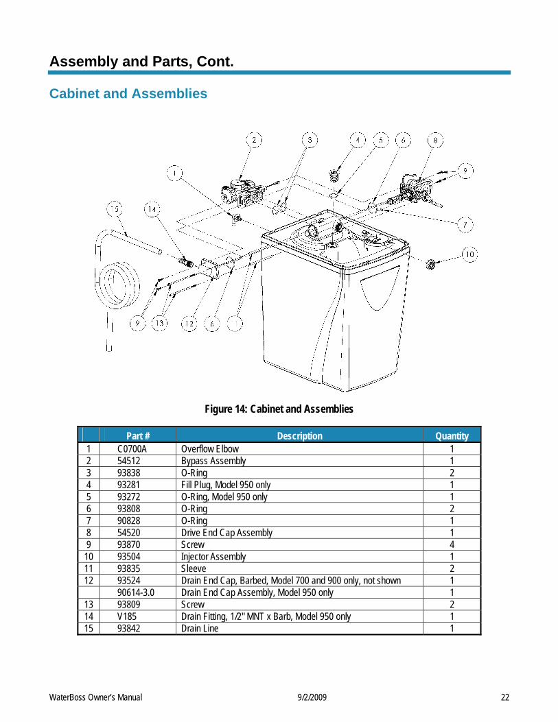
Figure 14: Cabinet and Assemblies
Part # Description Quantity 1 C0700A Overflow Elbow 1 2 54512 Bypass Assembly 1 3 93838 O-Ring 2 4 93281 Fill Plug, Model 950 only 1 5 93272 O-Ring, Model 950 only 1 6 93808 O-Ring 2 7 90828 O-Ring 1 8 54520 Drive End Cap Assembly 1 9 93870 Screw 4
10 93504 Injector Assembly 1 11 93835 Sleeve 2 12 93524 Drain End Cap, Barbed, Model 700 and 900 only, not shown 1 90614-3.0 Drain End Cap Assembly, Model 950 only 1
13 93809 Screw 2 14 V185 Drain Fitting, 1/2" MNT x Barb, Model 950 only 1 15 93842 Drain Line 1
WaterBoss Owner’s Manual 9/2/2009 22
Assembly and Parts, Cont.
Injector Assembly
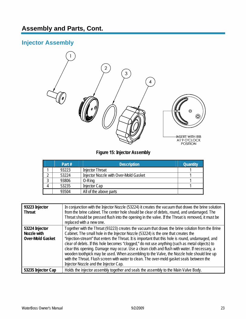
Figure 15: Injector Assembly
Part # Description Quantity 1 93223 Injector Throat 1 2 53224 Injector Nozzle with Over-Mold Gasket 1 3 93806 O-Ring 1 4 53235 Injector Cap 1 93504 All of the above parts
93223 Injector Throat
In conjunction with the Injector Nozzle (53224) it creates the vacuum that draws the brine solution from the brine cabinet. The center hole should be clear of debris, round, and undamaged. The Throat should be pressed flush into the opening in the valve. If the Throat is removed, it must be replaced with a new one.
53224 Injector Nozzle with Over-Mold Gasket
Together with the Throat (93223) creates the vacuum that draws the brine solution from the Brine Cabinet. The small hole in the Injector Nozzle (53224) is the one that creates the “injection-stream” that enters the Throat. It is important that this hole is round, undamaged, and clear of debris. If this hole becomes “clogged,” do not use anything (such as metal objects) to clear this opening. Damage may occur. Use a clean cloth and flush with water. If necessary, a wooden toothpick may be used. When assembling to the Valve, the Nozzle hole should line up with the Throat. Flush screen with water to clean. The over-mold gasket seals between the Injector Nozzle and the Injector Cap.
53235 Injector Cap Holds the injector assembly together and seals the assembly to the Main Valve Body.
WaterBoss Owner’s Manual 9/2/2009 23
Assembly and Parts, Cont.
Bypass Assembly
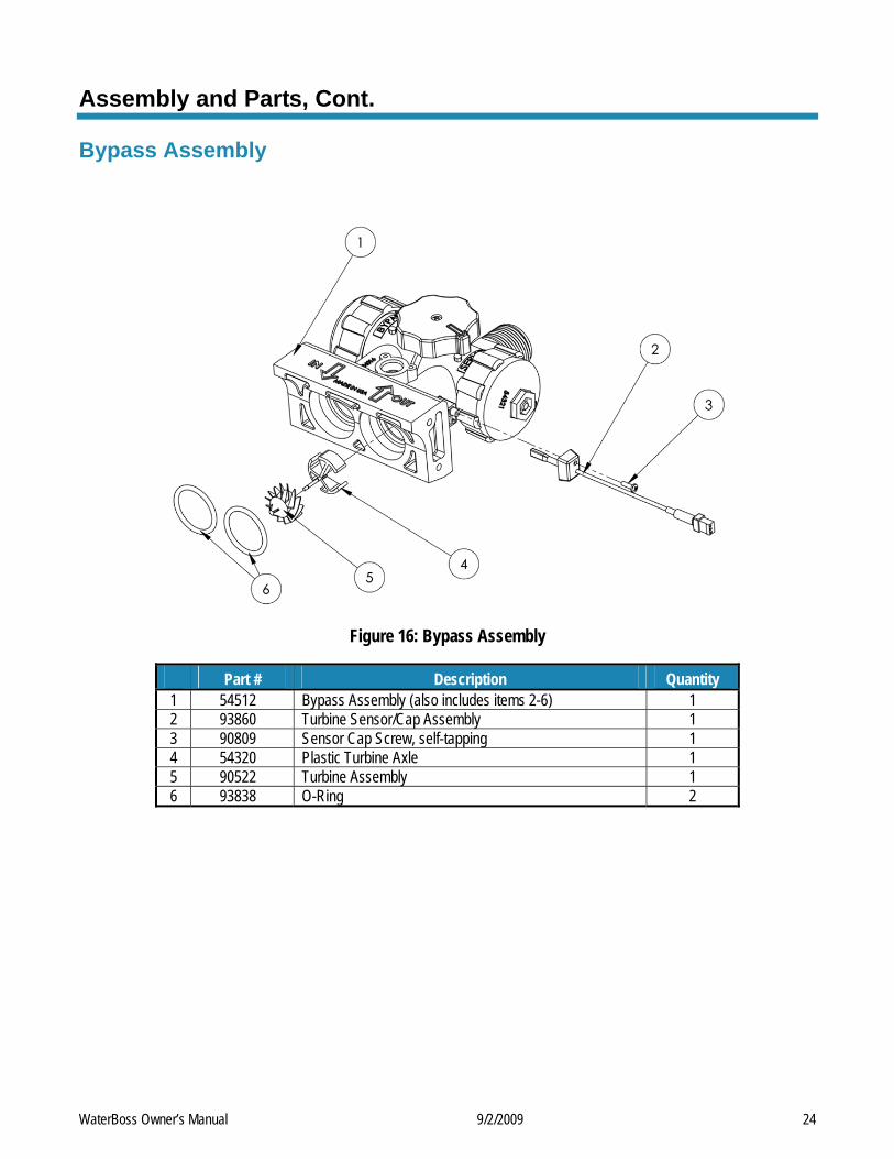
Figure 16: Bypass Assembly
Part # Description Quantity 1 54512 Bypass Assembly (also includes items 2-6) 1 2 93860 Turbine Sensor/Cap Assembly 1 3 90809 Sensor Cap Screw, self-tapping 1 4 54320 Plastic Turbine Axle 1 5 90522 Turbine Assembly 1 6 93838 O-Ring 2
WaterBoss Owner’s Manual 9/2/2009 24
Assembly and Parts, Cont.
Top Fill Plug Assembly (950)
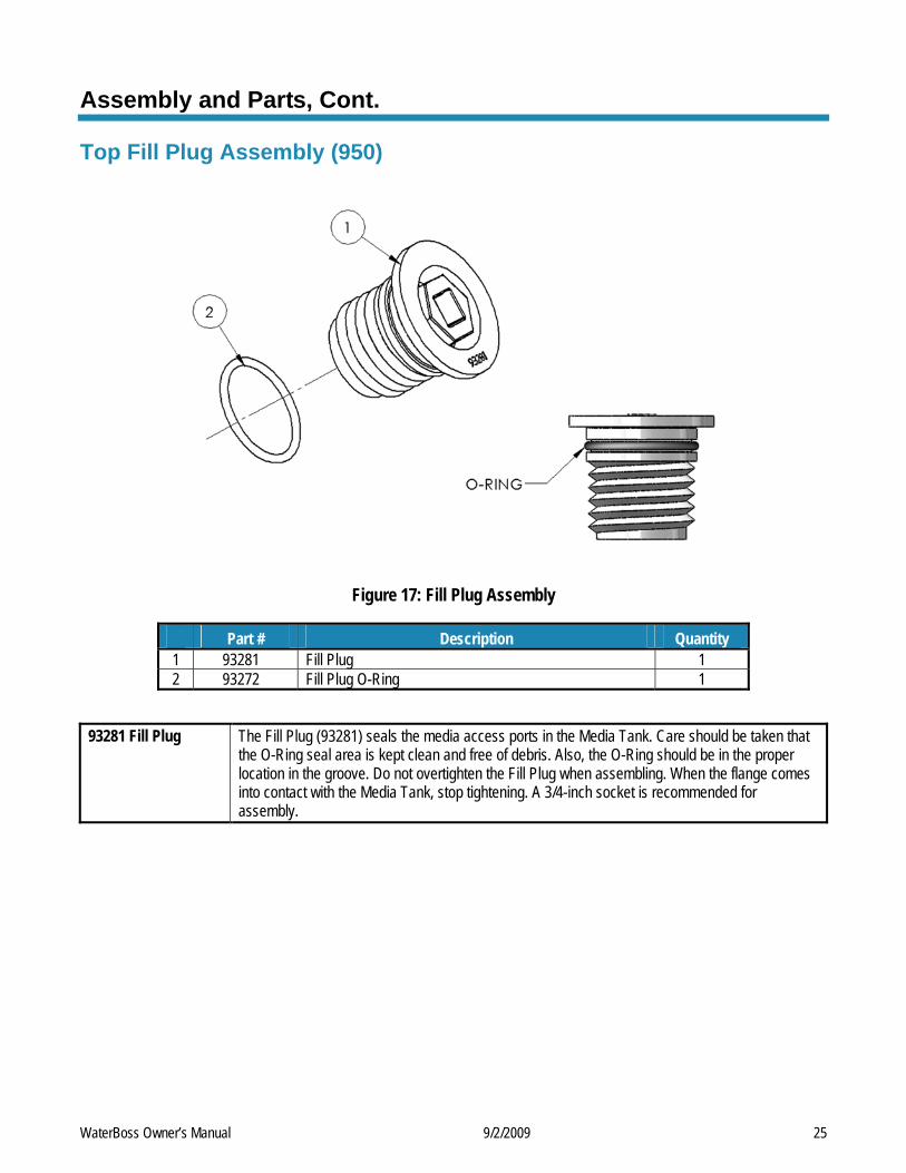
Figure 17: Fill Plug Assembly
Part # Description Quantity 1 93281 Fill Plug 1 2 93272 Fill Plug O-Ring 1
93281 Fill Plug The Fill Plug (93281) seals the media access ports in the Media Tank. Care should be taken that
the O-Ring seal area is kept clean and free of debris. Also, the O-Ring should be in the proper location in the groove. Do not overtighten the Fill Plug when assembling. When the flange comes into contact with the Media Tank, stop tightening. A 3/4-inch socket is recommended for assembly.
WaterBoss Owner’s Manual 9/2/2009 25
Assembly and Parts, Cont.
Drive End Cap Assembly
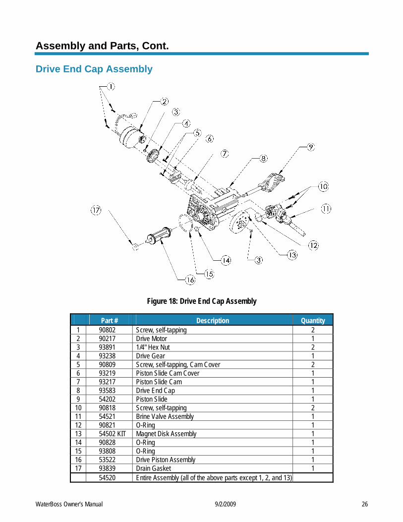
Figure 18: Drive End Cap Assembly
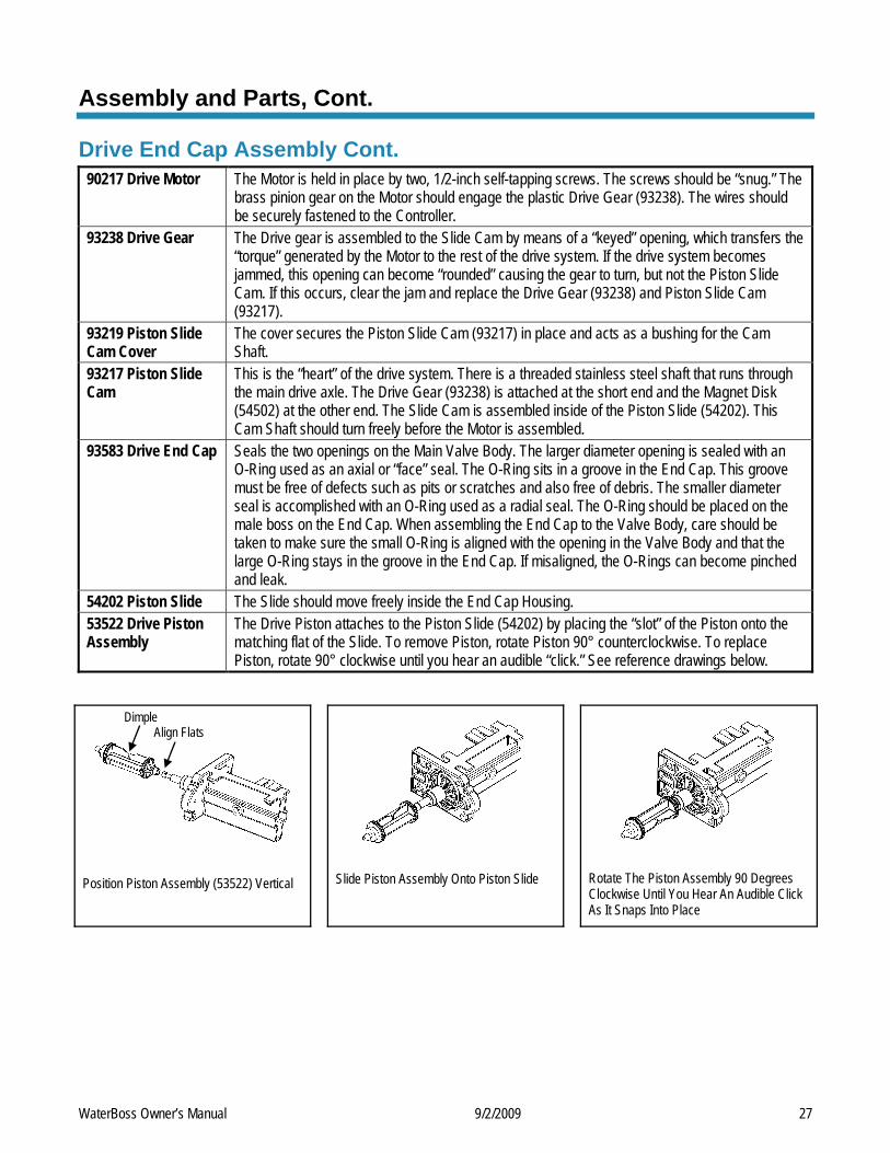
Part # Description Quantity 1 90802 Screw, self-tapping 2 2 90217 Drive Motor 1 3 93891 1/4" Hex Nut 2 4 93238 Drive Gear 1 5 90809 Screw, self-tapping, Cam Cover 2 6 93219 Piston Slide Cam Cover 1 7 93217 Piston Slide Cam 1 8 93583 Drive End Cap 1 9 54202 Piston Slide 1
10 90818 Screw, self-tapping 2 11 54521 Brine Valve Assembly 1 12 90821 O-Ring 1 13 54502 KIT Magnet Disk Assembly 1 14 90828 O-Ring 1 15 93808 O-Ring 1 16 53522 Drive Piston Assembly 1 17 93839 Drain Gasket 1 54520 Entire Assembly (all of the above parts except 1, 2, and 13)
WaterBoss Owner’s Manual 9/2/2009 26
Assembly and Parts, Cont.
Drive End Cap Assembly Cont. 90217 Drive Motor The Motor is held in place by two, 1/2-inch self-tapping screws. The screws should be “snug.” The
brass pinion gear on the Motor should engage the plastic Drive Gear (93238). The wires should be securely fastened to the Controller.
93238 Drive Gear The Drive gear is assembled to the Slide Cam by means of a “keyed” opening, which transfers the “torque” generated by the Motor to the rest of the drive system. If the drive system becomes jammed, this opening can become “rounded” causing the gear to turn, but not the Piston Slide Cam. If this occurs, clear the jam and replace the Drive Gear (93238) and Piston Slide Cam (93217).
93219 Piston Slide Cam Cover
The cover secures the Piston Slide Cam (93217) in place and acts as a bushing for the Cam Shaft.
93217 Piston Slide Cam
This is the “heart” of the drive system. There is a threaded stainless steel shaft that runs through the main drive axle. The Drive Gear (93238) is attached at the short end and the Magnet Disk (54502) at the other end. The Slide Cam is assembled inside of the Piston Slide (54202). This Cam Shaft should turn freely before the Motor is assembled.
93583 Drive End Cap Seals the two openings on the Main Valve Body. The larger diameter opening is sealed with an O-Ring used as an axial or “face” seal. The O-Ring sits in a groove in the End Cap. This groove must be free of defects such as pits or scratches and also free of debris. The smaller diameter seal is accomplished with an O-Ring used as a radial seal. The O-Ring should be placed on the male boss on the End Cap. When assembling the End Cap to the Valve Body, care should be taken to make sure the small O-Ring is aligned with the opening in the Valve Body and that the large O-Ring stays in the groove in the End Cap. If misaligned, the O-Rings can become pinched and leak.
54202 Piston Slide The Slide should move freely inside the End Cap Housing. 53522 Drive Piston Assembly
The Drive Piston attaches to the Piston Slide (54202) by placing the “slot” of the Piston onto the matching flat of the Slide. To remove Piston, rotate Piston 90° counterclockwise. To replace Piston, rotate 90° clockwise until you hear an audible “click.” See reference drawings below.
Position Piston Assembly (53522) Vertical
Slide Piston Assembly Onto Piston Slide
Rotate The Piston Assembly 90 Degrees Clockwise Until You Hear An Audible Click As It Snaps Into Place
Dimple Align Flats
WaterBoss Owner’s Manual 9/2/2009 27
Assembly and Parts, Cont.
Brine Valve Housing Assembly
Concave side Static O-Ring
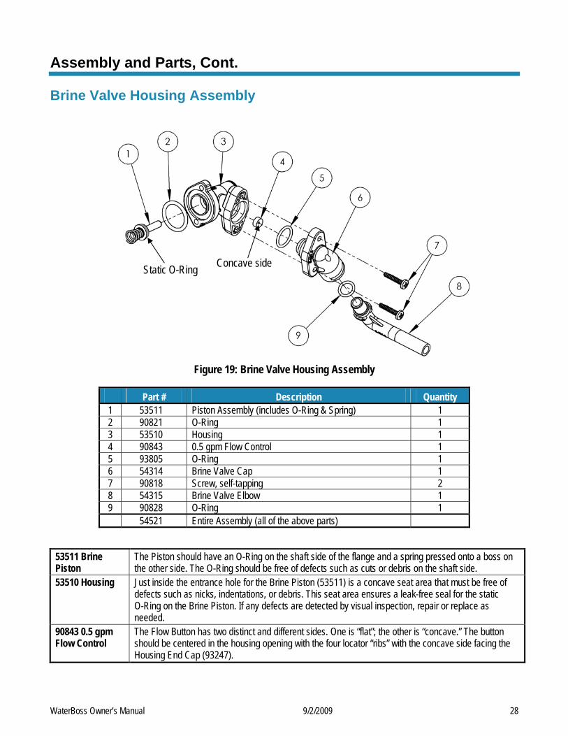
Figure 19: Brine Valve Housing Assembly
Part # Description Quantity 1 53511 Piston Assembly (includes O-Ring & Spring) 1 2 90821 O-Ring 1 3 53510 Housing 1 4 90843 0.5 gpm Flow Control 1 5 93805 O-Ring 1 6 54314 Brine Valve Cap 1 7 90818 Screw, self-tapping 2 8 54315 Brine Valve Elbow 1 9 90828 O-Ring 1 54521 Entire Assembly (all of the above parts)
53511 Brine Piston
The Piston should have an O-Ring on the shaft side of the flange and a spring pressed onto a boss on the other side. The O-Ring should be free of defects such as cuts or debris on the shaft side.
53510 Housing Just inside the entrance hole for the Brine Piston (53511) is a concave seat area that must be free of defects such as nicks, indentations, or debris. This seat area ensures a leak-free seal for the static O-Ring on the Brine Piston. If any defects are detected by visual inspection, repair or replace as needed.
90843 0.5 gpm Flow Control
The Flow Button has two distinct and different sides. One is “flat”; the other is “concave.” The button should be centered in the housing opening with the four locator “ribs” with the concave side facing the Housing End Cap (93247).
WaterBoss Owner’s Manual 9/2/2009 28
Assembly and Parts, Cont.
Safety Shutoff Assembly
1
2
3
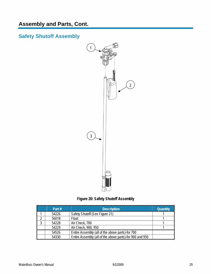
Figure 20: Safety Shutoff Assembly
Part # Description Quantity 1 54226 Safety Shutoff (See Figure 21) 1 2 56018 Float 1 3 54228 Air Check, 700 1 54229 Air Check, 900, 950 1 54526 Entire Assembly (all of the above parts)-for 700 54330 Entire Assembly (all of the above parts)-for 900 and 950
WaterBoss Owner’s Manual 9/2/2009 29
Assembly and Parts, Cont.
Safety Shutoff Valve Elbow Installation
3/8" Nut 3/8" Retainer Sleeve
3/8" Plastic Insert
3/8" Plastic Gripper
Safety Shutoff Valve 3/8" Poly Tube
2 Hex Nut
1
Wrist Pin 1/2" Retainer Sleeve
1/2" Plastic Gripper
1/2" Nut
Air Check/Draw Tube
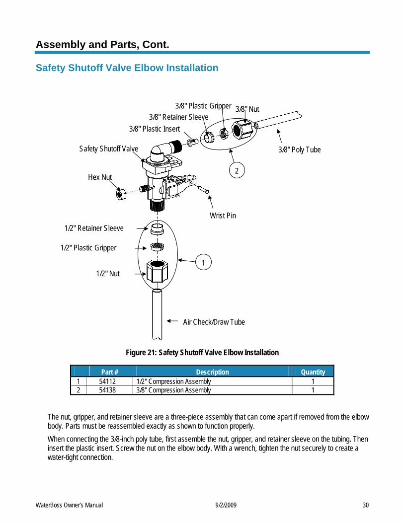
Figure 21: Safety Shutoff Valve Elbow Installation
Part # Description Quantity 1 54112 1/2" Compression Assembly 1 2 54138 3/8" Compression Assembly 1
The nut, gripper, and retainer sleeve are a three-piece assembly that can come apart if removed from the elbow body. Parts must be reassembled exactly as shown to function properly. When connecting the 3/8-inch poly tube, first assemble the nut, gripper, and retainer sleeve on the tubing. Then insert the plastic insert. Screw the nut on the elbow body. With a wrench, tighten the nut securely to create a water-tight connection.
WaterBoss Owner’s Manual 9/2/2009 30
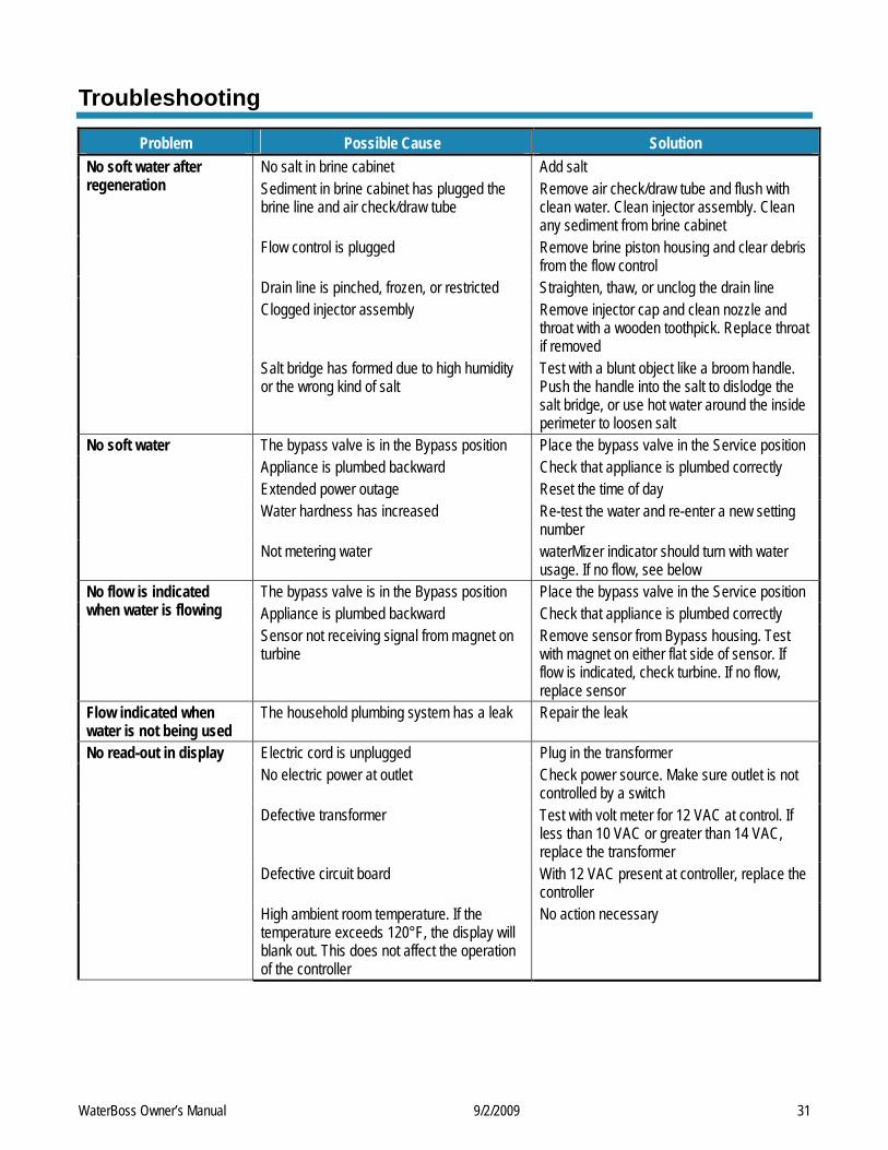
Troubleshooting
Problem Possible Cause Solution No salt in brine cabinet Add salt Sediment in brine cabinet has plugged the brine line and air check/draw tube
Remove air check/draw tube and flush with clean water. Clean injector assembly. Clean any sediment from brine cabinet
Flow control is plugged Remove brine piston housing and clear debris from the flow control
Drain line is pinched, frozen, or restricted Straighten, thaw, or unclog the drain line Clogged injector assembly Remove injector cap and clean nozzle and
throat with a wooden toothpick. Replace throat if removed
No soft water after regeneration
Salt bridge has formed due to high humidity or the wrong kind of salt
Test with a blunt object like a broom handle. Push the handle into the salt to dislodge the salt bridge, or use hot water around the inside perimeter to loosen salt
The bypass valve is in the Bypass position Place the bypass valve in the Service position Appliance is plumbed backward Check that appliance is plumbed correctly Extended power outage Reset the time of day Water hardness has increased Re-test the water and re-enter a new setting
number
No soft water
Not metering water waterMizer indicator should turn with water usage. If no flow, see below
The bypass valve is in the Bypass position Place the bypass valve in the Service position Appliance is plumbed backward Check that appliance is plumbed correctly
No flow is indicated when water is flowing
Sensor not receiving signal from magnet on turbine
Remove sensor from Bypass housing. Test with magnet on either flat side of sensor. If flow is indicated, check turbine. If no flow, replace sensor
Flow indicated when water is not being used
The household plumbing system has a leak Repair the leak
Electric cord is unplugged Plug in the transformer No electric power at outlet Check power source. Make sure outlet is not
controlled by a switch Defective transformer Test with volt meter for 12 VAC at control. If
less than 10 VAC or greater than 14 VAC, replace the transformer
Defective circuit board With 12 VAC present at controller, replace the controller
No read-out in display
High ambient room temperature. If the temperature exceeds 120°F, the display will blank out. This does not affect the operation of the controller
No action necessary
WaterBoss Owner’s Manual 9/2/2009 31
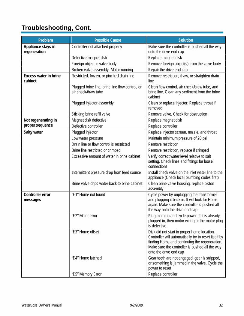
Troubleshooting, Cont.
Problem Possible Cause Solution Controller not attached properly Make sure the controller is pushed all the way
onto the drive end cap Defective magnet disk Replace magnet disk Foreign object in valve body Remove foreign object(s) from the valve body
Appliance stays in regeneration
Broken valve assembly. Motor running Repair the drive end cap Restricted, frozen, or pinched drain line Remove restriction, thaw, or straighten drain
line Plugged brine line, brine line flow control, or air check/draw tube
Clean flow control, air check/draw tube, and brine line. Clean any sediment from the brine cabinet
Plugged injector assembly Clean or replace injector. Replace throat if removed
Excess water in brine cabinet
Sticking brine refill valve Remove valve. Check for obstruction Magnet disk defective Replace magnet disk Not regenerating in
proper sequence Defective controller Replace controller Plugged injector Replace injector screen, nozzle, and throat Low water pressure Maintain minimum pressure of 20 psi Drain line or flow control is restricted Remove restriction Brine line restricted or crimped Remove restriction, replace if crimped Excessive amount of water in brine cabinet Verify correct water level relative to salt
setting. Check lines and fittings for loose connections
Intermittent pressure drop from feed source Install check valve on the inlet water line to the appliance (Check local plumbing codes first)
Salty water
Brine valve drips water back to brine cabinet Clean brine valve housing, replace piston assembly
“E1” Home not found Cycle power by unplugging the transformer and plugging it back in. It will look for Home again. Make sure the controller is pushed all the way onto the drive end cap
“E2” Motor error Plug motor in and cycle power. If it is already plugged in, then motor wiring or the motor plug is defective
“E3” Home offset Disk did not start in proper home location. Controller will automatically try to reset itself by finding Home and continuing the regeneration. Make sure the controller is pushed all the way onto the drive end cap
“E4” Home latched Gear teeth are not engaged, gear is stripped, or something is jammed in the valve. Cycle the power to reset
Controller error messages
“E5” Memory Error Replace controller
WaterBoss Owner’s Manual 9/2/2009 32
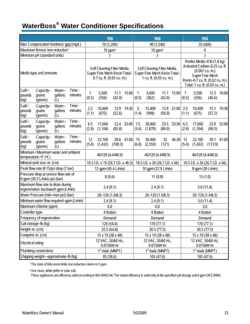
WaterBoss® Water Conditioner Specifications
700 900 950 Max Compensated Hardness gpg (mg/L) 70 (1,200) 90 (1,540) 35 (600) Maximum ferrous iron reduction1 10 ppm1 10 ppm1 0 Minimum pH (standard units) 7 7 7
Media type and amounts Self Cleaning Filter Media.
Super Fine Mesh Resin Total–0.7 cu. ft. (0.02 cu. m.)
Self Cleaning Filter Media. Super Fine Mesh Resin Total–
1 cu. ft. (0.03 cu. m.)
Redox Media–4 lb (1.8 kg) Activated Carbon–0.25 cu. ft.
(0.007 cu. m.) Super Fine Mesh
Resin–0.7 cu. ft. (0.02 cu. m.) Total: 1 cu. ft. (0.03 cu. m.)
Salt2– pounds (kg)
Capacity–grains (grams)
Water–gallons (L)
Time–minutes
1 (0.5)
5,500 (356)
11.1 (42.0)
15:00
1 (0.5)
5,600 (362)
11.1 (42.0)
15:00
1 (0.5)
5,500 (356)
12.3 (46.6)
16:00
Salt2– pounds (kg)
Capacity–grains (grams)
Water–gallons (L)
Time–minutes
2.5 (1.1)
10,400 (675)
13.9 (52.6)
19:30
3 (1.4)
15,400 (998)
13.9 (56.0)
21:00
2.5 (1.1)
10,400 (675)
15.1 (57.2)
19:30
Salt2– pounds (kg)
Capacity–grains (grams)
Water–gallons (L)
Time–minutes
6.5 (2.9)
17,000 (1,104)
22.4 (85.8)
32:00
7.5 (3.4)
28,800 (1,870)
23.5 (89.0)
33:30
6.5 (2.9)
17,000 (1,104)
23.9 (90.5)
32:00
Salt2– pounds (kg)
Capacity–grains (grams)
Water–gallons (L)
Time–minutes
12 (5.4)
22,100 (1,432)
28.6 (108.3)
41:00
15 (6.8)
36,400 (2,359)
32 (121)
46:30
12 (5.4)
22,100 (1,432)
30.1 (113.9)
41:00
Minimum / Maximum water and ambient temperature–oF (oC) 40/120 (4.4/48.9) 40/120 (4.4/48.9) 40/120 (4.4/48.9)
Mineral tank size–in. (cm) 10.5 I.D. x 19 (26.7 I.D. x 48.3) 10.5 I.D. x 26 (26.7 I.D. x 66) 10.5 I.D. x 26 (26.7 I.D. x 66) Peak flow rate @15/psi drop (1 bar) 12 gpm (45.4 L/min) 10 gpm (37.9 L/min) 8 gpm (30 L/min) Pressure drop at service flow rate of 8 gpm (30.3 L/min)–psi (bar) 8 (0.6) 11 (0.8) 15 (1.0)
Maximum flow rate to drain during regeneration–backwash gpm (L/min) 2.4 (9.1) 2.4 (9.1) 3.0 (11.4)
Water Pressure (min–max psi) (bar) 20–120 (1.4/8.3) 20–120 (1.4/8.3) 20–120 (1.4/8.3) Minimum water flow required–gpm (L/min) 2.4 (9.1) 2.4 (9.1) 3.0 (11.4) Maximum chlorine (ppm) 0.0 0.0 3.0 Controller type 4 Button 4 Button 4 Button Frequency of regeneration Demand Demand Demand Salt storage–lb (kg) 120 (54.4) 170 (77.1) 170 (77.1) Height–in. (cm) 25.5 (64.8) 30.5 (77.5) 30.5 (77.5) Footprint–in. (cm) 15 x 19 (38 x 48) 15 x 19 (38 x 48) 15 x 19 (38 x 48)
Electrical rating 12 VAC, 50/60 Hz, 0.015kW-hr
12 VAC, 50/60 Hz, 0.015kW-hr
12 VAC, 50/60 Hz, 0.015kW-hr
Plumbing connections 1" male (MNPT) 1" male (MNPT) 1" male (MNPT) Shipping weight—approximate–lb (kg) 85 (38.6) 105 (47.6) 105 (47.6)
1 The state of Wisconsin limits iron reduction claims to 5 ppm. 2 Use clean, white pellet or solar salt. These appliances are efficiency rated according to NSF/ANSI 44. The stated efficiency is valid only at the specified salt dosage and 8 gpm (30 L/min).
WaterBoss Owner’s Manual 9/2/2009 33

WaterBoss Owner’s Manual 9/2/2009 34
Certificates

Notes

WaterBoss® has these third-party listings:
In Business Since 1956
www.waterboss.com 4343 South Hamilton Road, Groveport, OH 43125
LITHO USA ©2009 F93966 OR0809HQWI


![Don’t gamble with physical properties – Kein Glücksspiel ... · AspenTech, CHEMCAD ... x HCl [mol/mol] VLE HCl-H2O, Aspen V7.2 Aspen V7.2 Aspen V7.2 Othmer,D.F, Ind. Eng. Chem](https://img.pdfslide.net/doc/110x75/5b58ae057f8b9a4e1b8c50a7/dont-gamble-with-physical-properties-kein-gluecksspiel-aspentech.jpg)