Embed Size (px)
Citation preview
WDM Concept and
Components
EE 8114
Course Notes
Part 1: WDM Concept
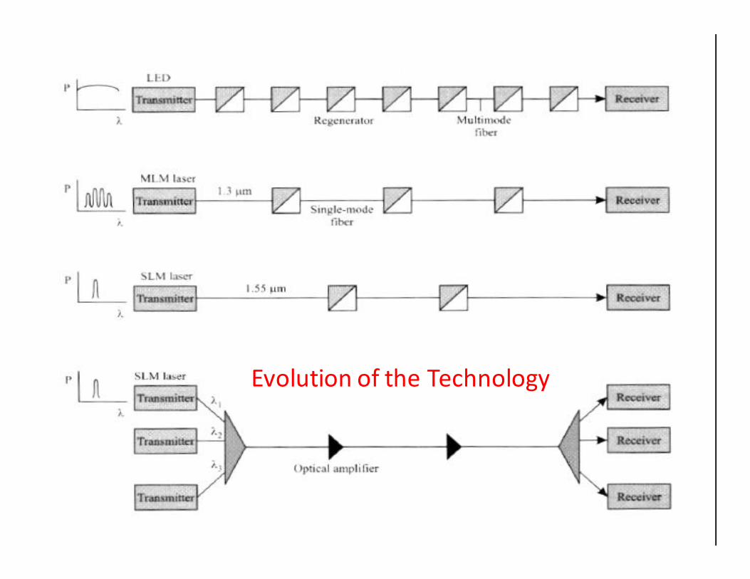
Evolution of the Technology
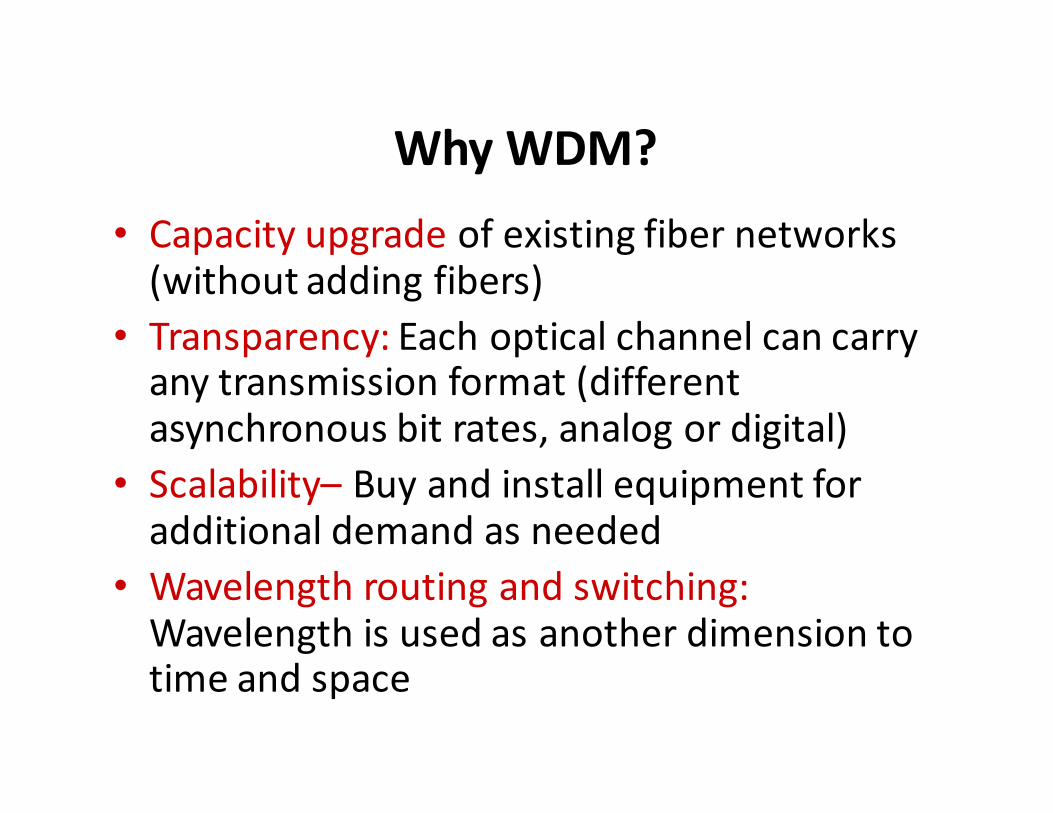
Why WDM?
• Capacity upgrade of existing fiber networks (without adding fibers)
• Transparency: Each optical channel can carry any transmission format (different asynchronous bit rates, analog or digital)
• Scalability– Buy and install equipment for additional demand as needed
• Wavelength routing and switching:Wavelength is used as another dimension to time and space
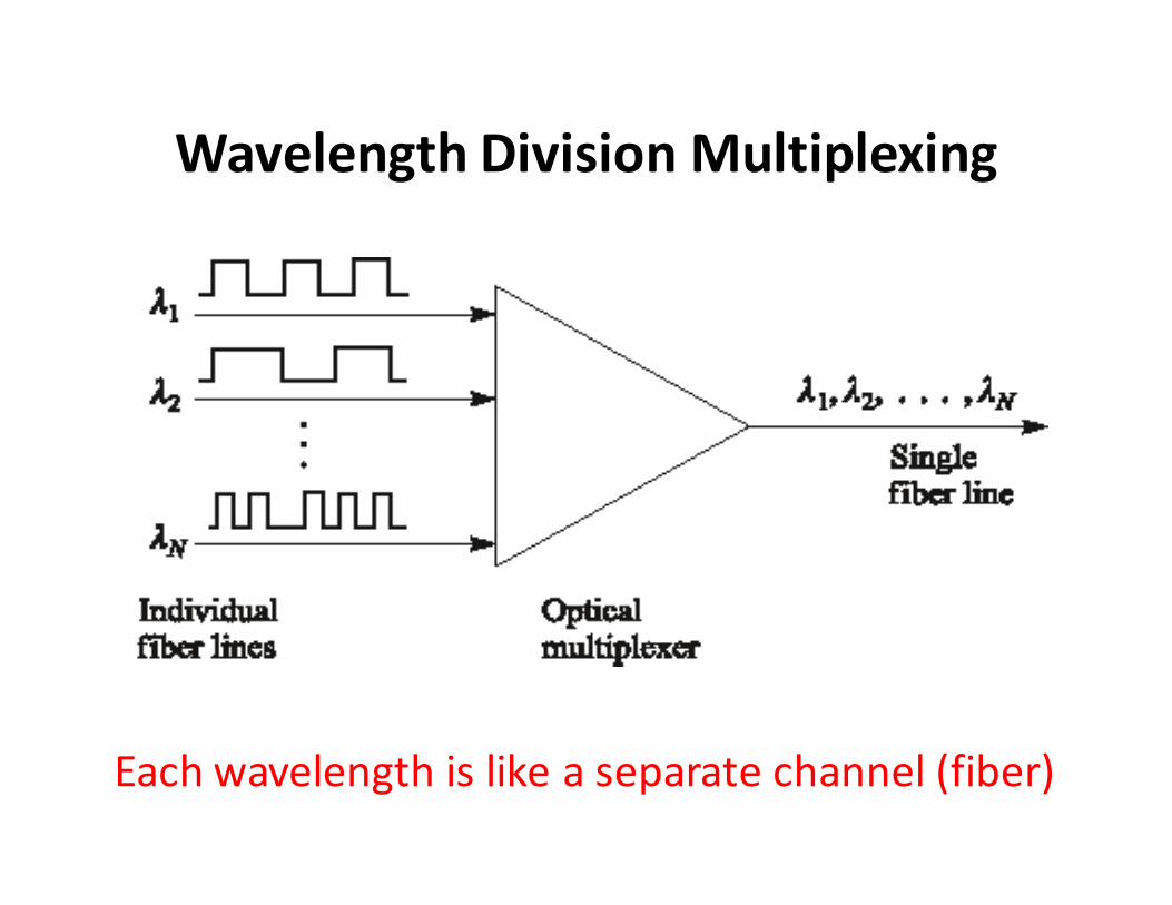
Wavelength Division Multiplexing
Each wavelength is like a separate channel (fiber)
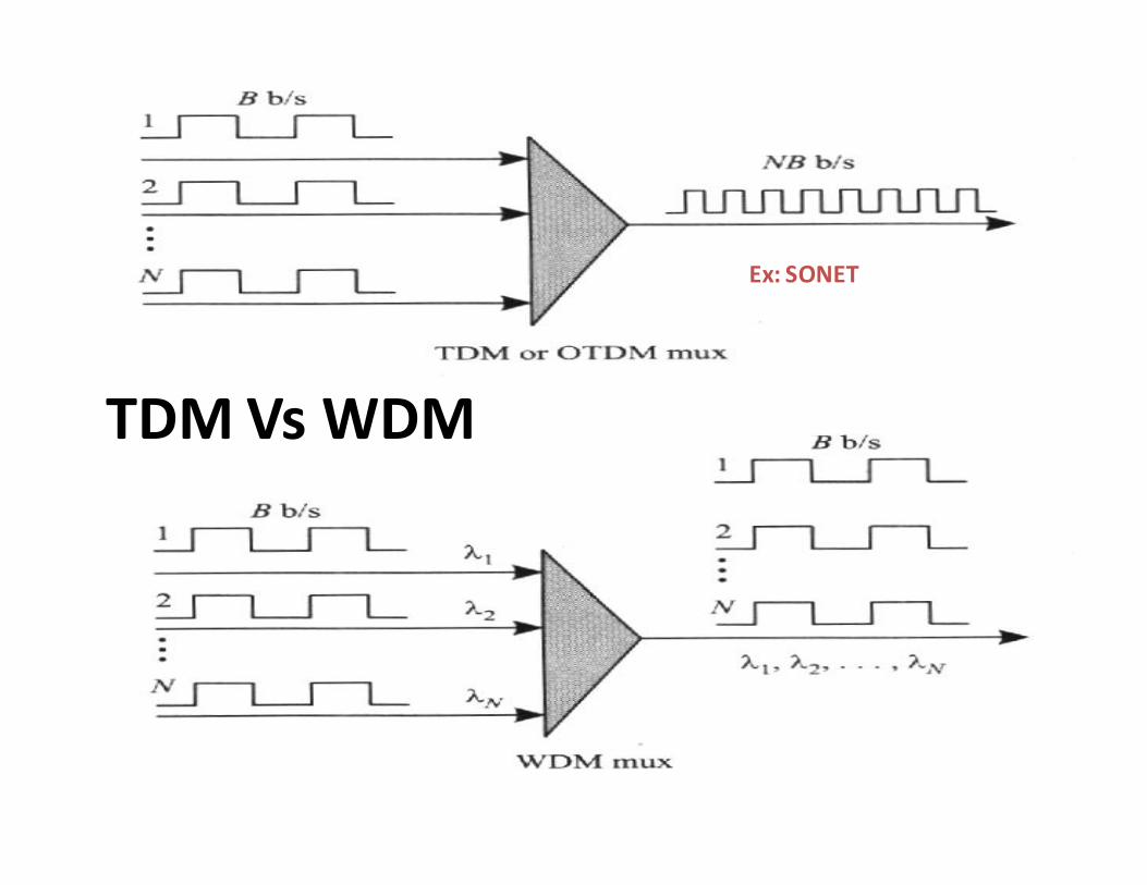
TDM Vs WDM
Ex: SONET
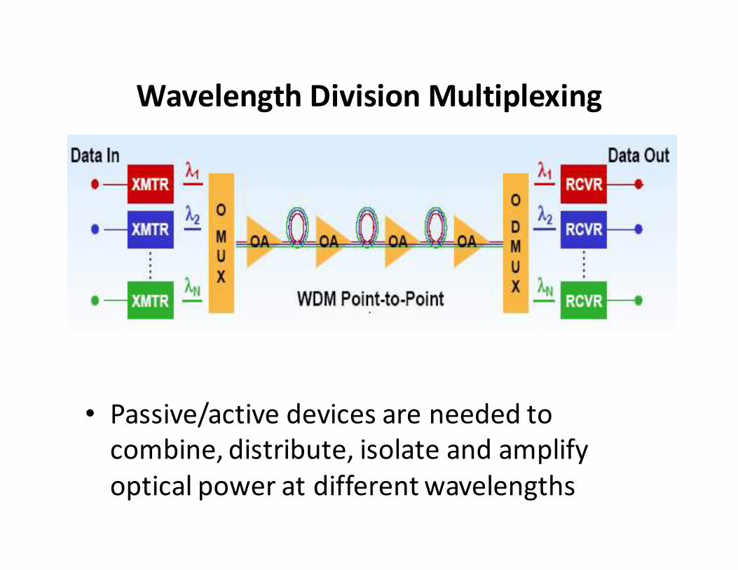
Wavelength Division Multiplexing
• Passive/active devices are needed to
combine, distribute, isolate and amplify
optical power at different wavelengths
WDM, CWDM and DWDM
• WDM technology uses multiple wavelengths
to transmit information over a single fiber
• Coarse WDM (CWDM) has wider channel
spacing (20 nm) – low cost
• Dense WDM (DWDM) has dense channel
spacing (0.8 nm) which allows simultaneous
transmission of 16+ wavelengths – high
capacity
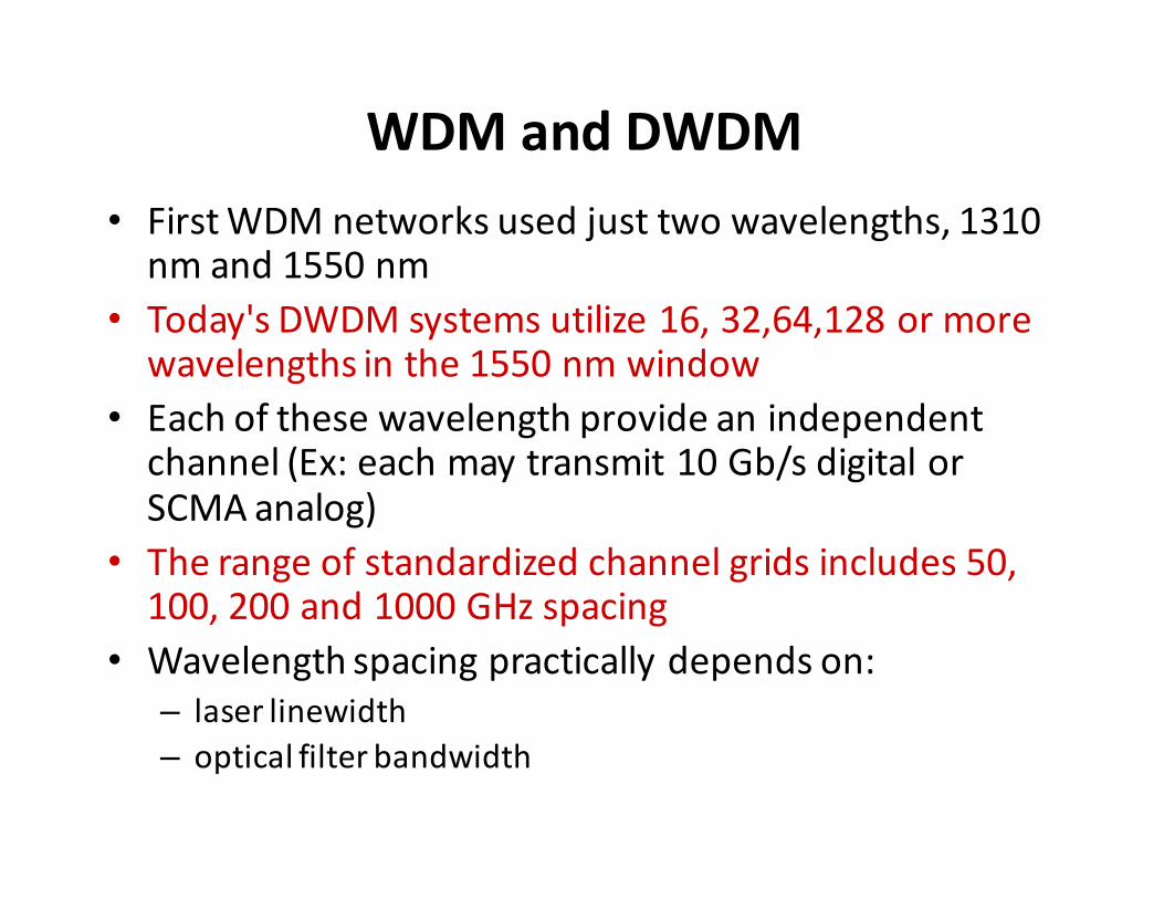
WDM and DWDM
• First WDM networks used just two wavelengths, 1310 nm and 1550 nm
• Today's DWDM systems utilize 16, 32,64,128 or more wavelengths in the 1550 nm window
• Each of these wavelength provide an independent channel (Ex: each may transmit 10 Gb/s digital or SCMA analog)
• The range of standardized channel grids includes 50, 100, 200 and 1000 GHz spacing
• Wavelength spacing practically depends on:
– laser linewidth
– optical filter bandwidth
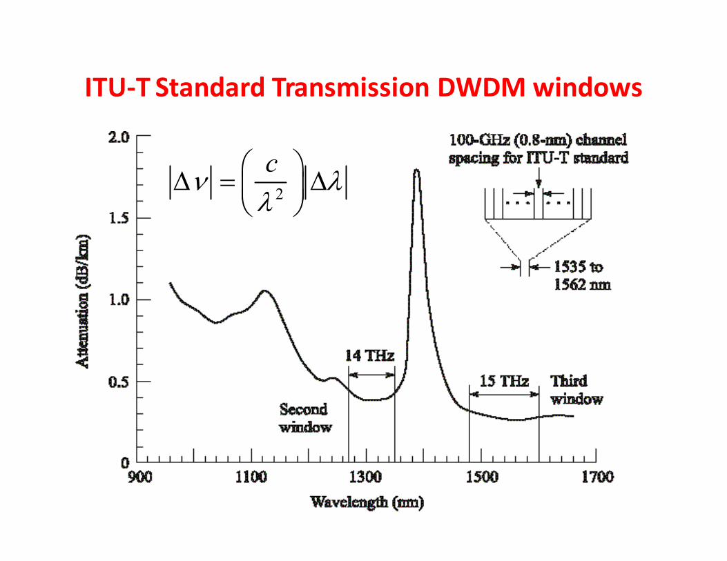
ITU-T Standard Transmission DWDM windows
2
cν λ
λ ∆ = ∆

Principles of DWDM
• BW of a modulated laser: 10-50 MHz � 0.001 nm
• Typical Guard band: 0.4 – 1.6 nm
• 80 nm or 14 THz @1300 nm band
• 120 nm or 15 THz @ 1550 nm
• Discrete wavelengths form individual channels that can
be modulated, routed and switched individually
• These operations require variety of passive and active
devices
2
cν λ
λ ∆ = ∆
Ex. 10.1
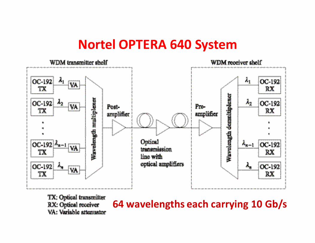
Nortel OPTERA 640 System
64 wavelengths each carrying 10 Gb/s
DWDM Limitations
Theoretically large number of channels can
be packed in a fiber
For physical realization of DWDM networks
we need precise wavelength selective
devices
Optical amplifiers are imperative to
provide long transmission distances
without repeaters
Part II: WDM Devices
Key Components for WDM
Passive Optical Components
• Wavelength Selective Splitters
• Wavelength Selective Couplers
Active Optical Components
• Tunable Optical Filter
• Tunable Source
• Optical amplifier
• Add-drop Multiplexer and De-multiplexer
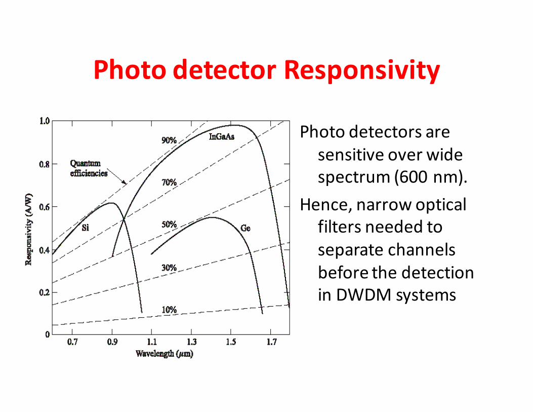
Photo detector Responsivity
Photo detectors are
sensitive over wide
spectrum (600 nm).
Hence, narrow optical
filters needed to
separate channels
before the detection
in DWDM systems
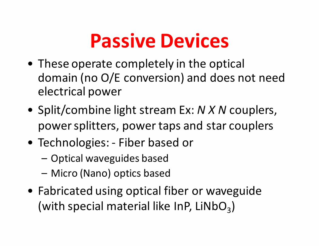
Passive Devices• These operate completely in the optical
domain (no O/E conversion) and does not need electrical power
• Split/combine light stream Ex: N X N couplers,
power splitters, power taps and star couplers
• Technologies: - Fiber based or
– Optical waveguides based
– Micro (Nano) optics based
• Fabricated using optical fiber or waveguide
(with special material like InP, LiNbO3)
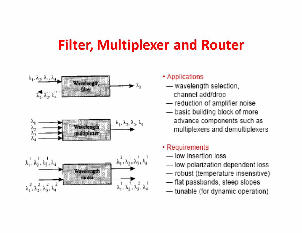
Filter, Multiplexer and Router
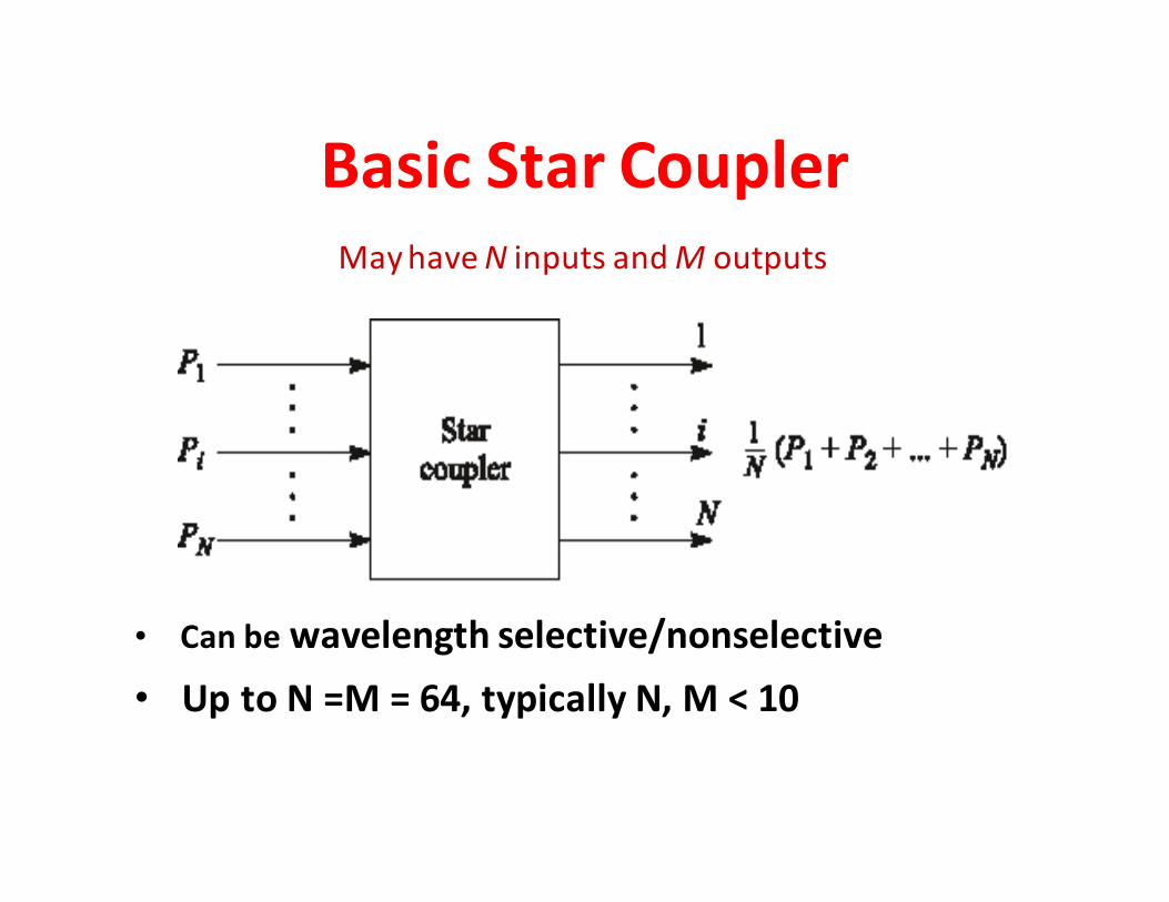
Basic Star Coupler
• Can be wavelength selective/nonselective
• Up to N =M = 64, typically N, M < 10
May have N inputs and M outputs
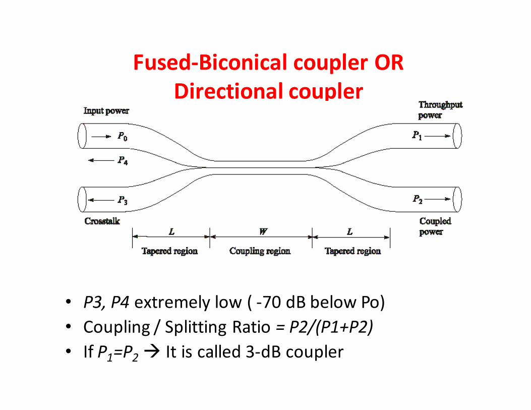
Fused-Biconical coupler OR
Directional coupler
• P3, P4 extremely low ( -70 dB below Po)
• Coupling / Splitting Ratio = P2/(P1+P2)
• If P1=P2 � It is called 3-dB coupler
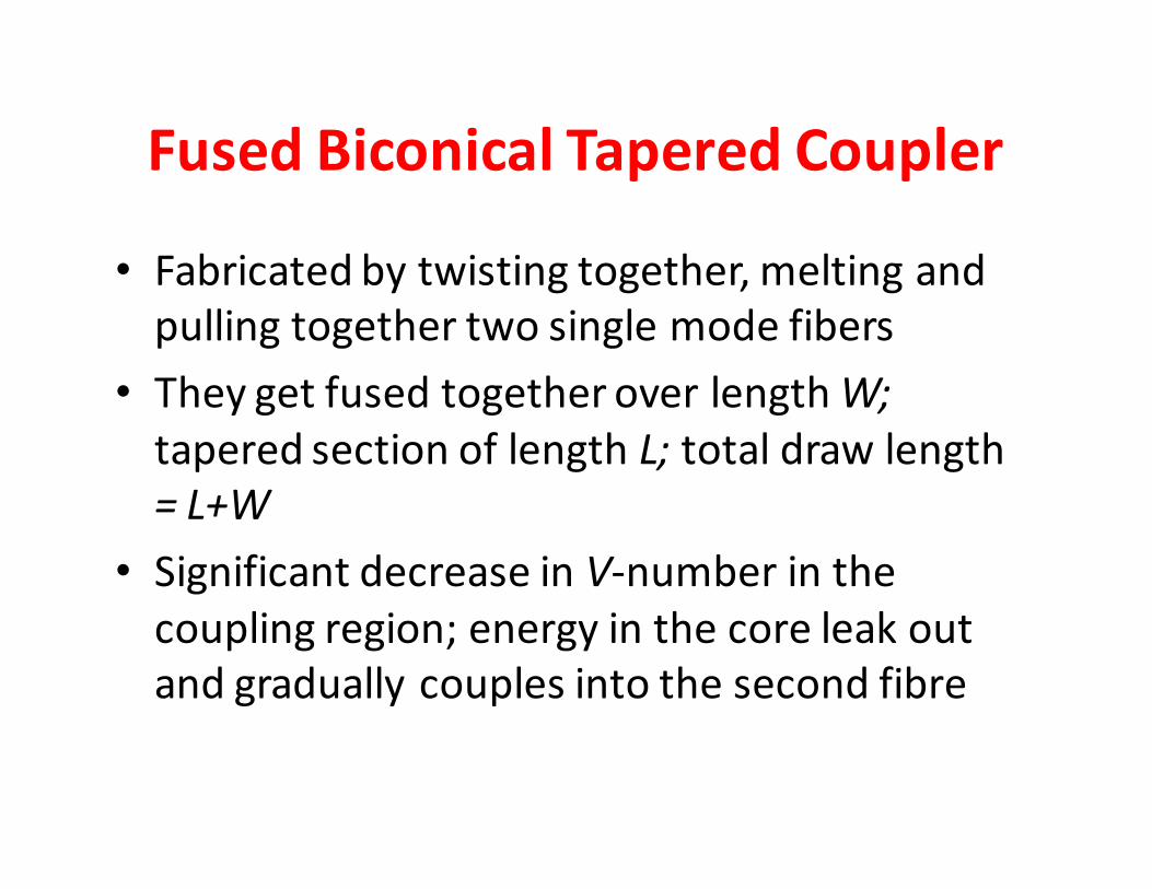
Fused Biconical Tapered Coupler
• Fabricated by twisting together, melting and
pulling together two single mode fibers
• They get fused together over length W;
tapered section of length L; total draw length
= L+W
• Significant decrease in V-number in the
coupling region; energy in the core leak out
and gradually couples into the second fibre

Definitions
2 1 2Splitting (Coupling) Rat = )i (o P P P+
0 1 2=10 LogExcess Lo [ss ( ] )P P P+
=1In 0 sert Log[ion Loss ] in outP P
3 0= 10 LoCrosstalk g( P P )
Try Ex. 10.2
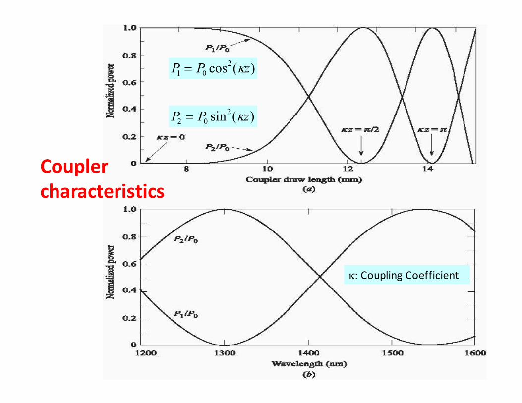
Coupler
characteristics
)(sin2
02 zPP κ=
)(cos2
01 zPP κ=
κ: Coupling Coefficient
Coupler Characteristics
• power ratio between both output can be
changed by adjusting the draw length of a simple
fused fiber coupler
• It can be made a WDM de-multiplexer:
• Example, 1300 nm will appear output 2 (p2) and 1550 nm
will appear at output 1 (P1)
• However, suitable only for few wavelengths that are far
apart, not good for DWDM
Wavelength Selective Devices
These perform their operation on the incoming
optical signal as a function of the wavelength
Examples:
• Wavelength add/drop multiplexers
• Wavelength selective optical combiners/splitters
• Wavelength selective switches and routers
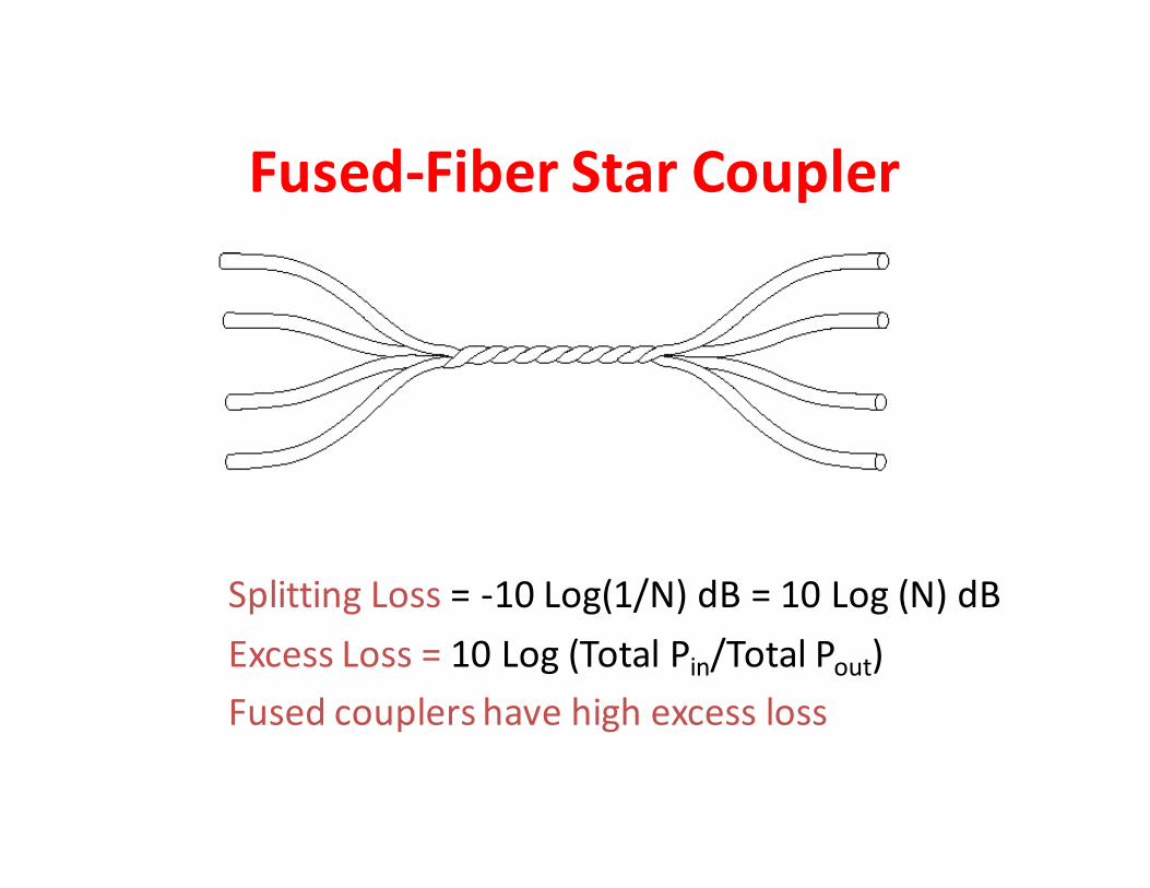
Fused-Fiber Star Coupler
Splitting Loss = -10 Log(1/N) dB = 10 Log (N) dB
Excess Loss = 10 Log (Total Pin/Total Pout)
Fused couplers have high excess loss
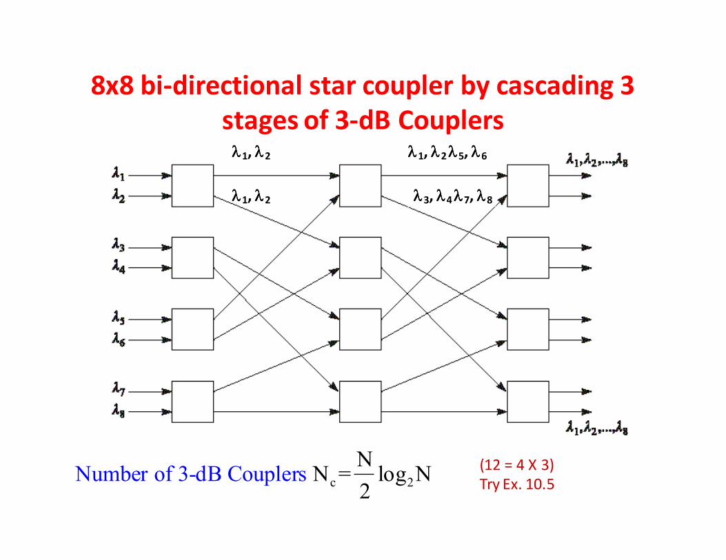
8x8 bi-directional star coupler by cascading 3
stages of 3-dB Couplers
c 2Number of 3-dB CouN
N = log N 2
plers (12 = 4 X 3)
Try Ex. 10.5
λλλλ1, λλλλ2
λλλλ1, λλλλ2
λλλλ1, λλλλ2 λλλλ5, λλλλ6
λλλλ3, λλλλ4 λλλλ7, λλλλ8
Fiber Bragg Grating
Fiber Bragg Grating
• This is invented at Communication Research
Center, Ottawa, Canada
• The FBG has changed the way optical filtering
is done
• The FBG has so many applications
• The FBG changes a single mode fiber (all pass
filter) into a wavelength selective filter
Fiber Brag Grating (FBG)
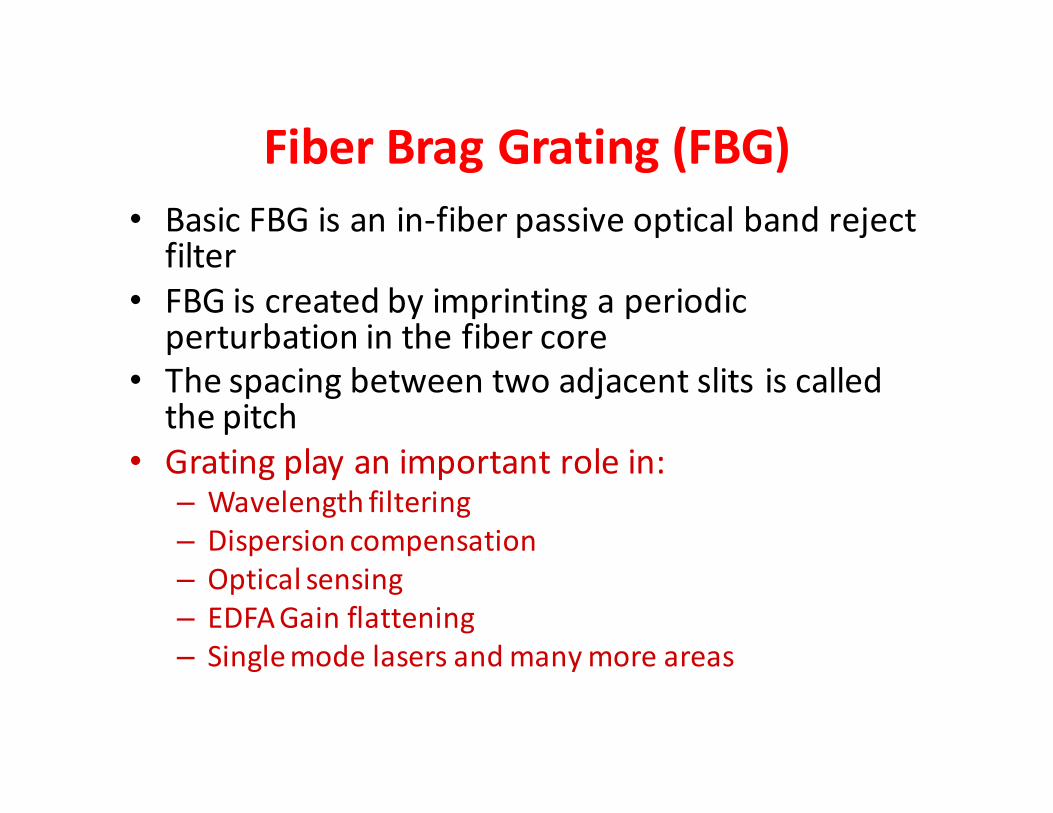
• Basic FBG is an in-fiber passive optical band reject filter
• FBG is created by imprinting a periodic perturbation in the fiber core
• The spacing between two adjacent slits is called the pitch
• Grating play an important role in:– Wavelength filtering
– Dispersion compensation
– Optical sensing
– EDFA Gain flattening
– Single mode lasers and many more areas
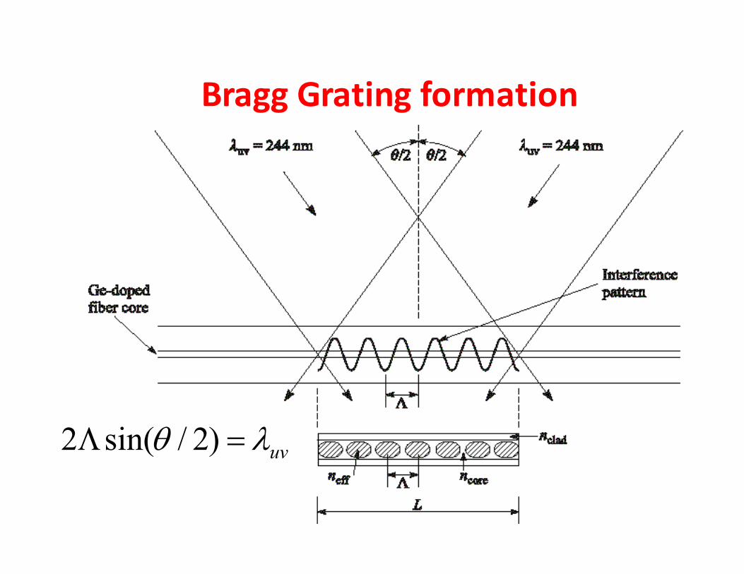
Bragg Grating formation
uvλθ =Λ )2/sin(2
FBG Theory
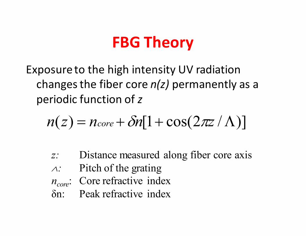
Exposure to the high intensity UV radiation
changes the fiber core n(z) permanently as a
periodic function of z
)]/2cos(1[)( Λ++= znnzn core πδ
z: Distance measured along fiber core axis
∧: Pitch of the grating
ncore: Core refractive index
δn: Peak refractive index
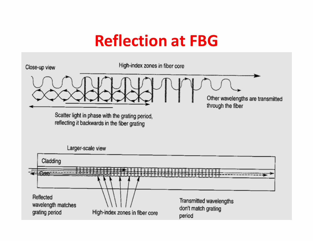
Reflection at FBG
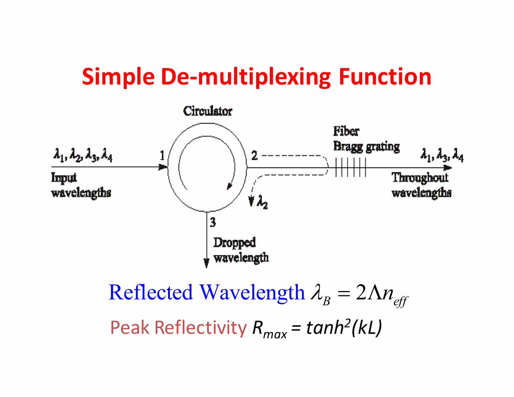
Simple De-multiplexing Function
Reflected Wavelength 2B effnλ = Λ
Peak Reflectivity Rmax = tanh2(kL)

Wavelength Selective DEMUX
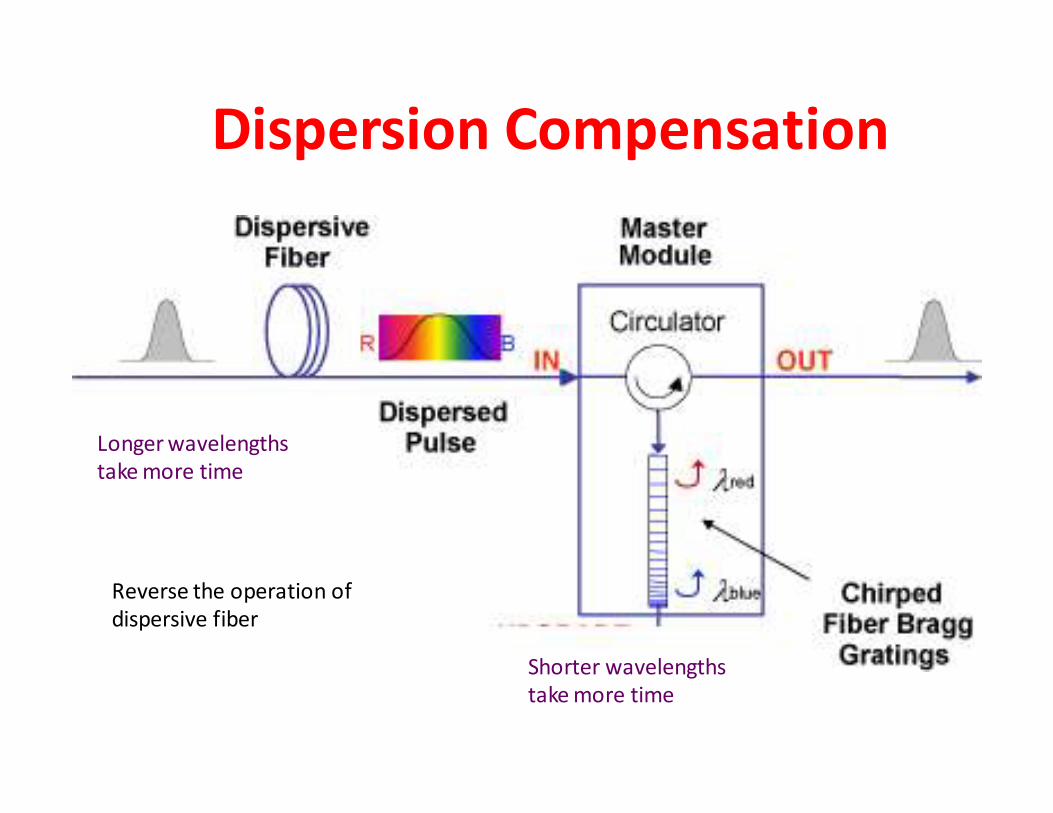
Dispersion Compensation
Longer wavelengths
take more time
Shorter wavelengths
take more time
Reverse the operation of
dispersive fiber
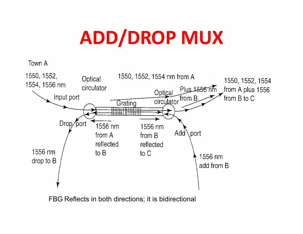
ADD/DROP MUX
FBG Reflects in both directions; it is bidirectional
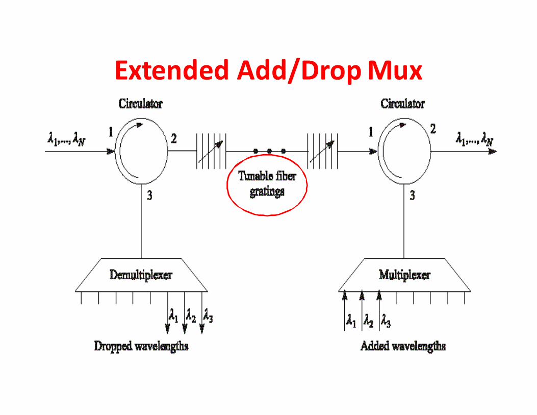
Extended Add/Drop Mux
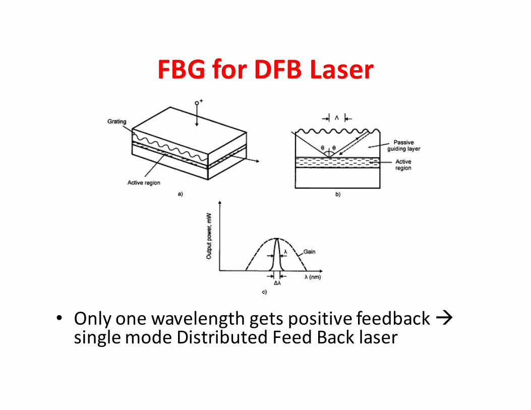
FBG for DFB Laser
• Only one wavelength gets positive feedback �single mode Distributed Feed Back laser
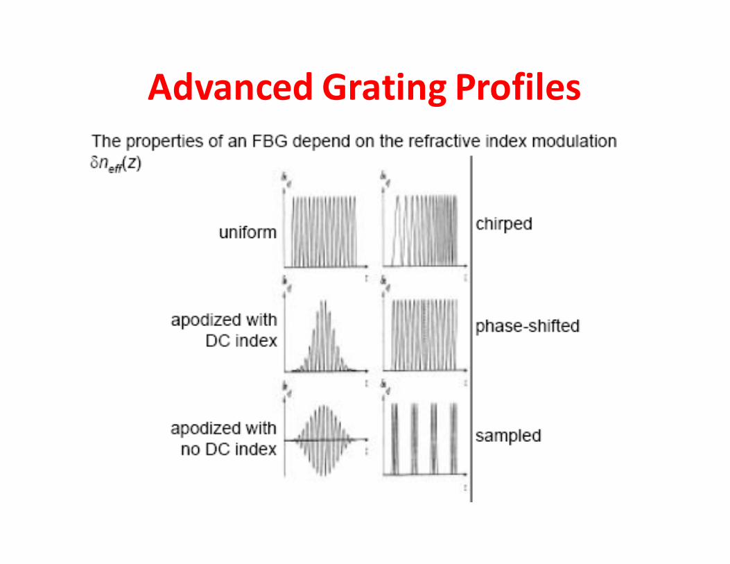
Advanced Grating Profiles
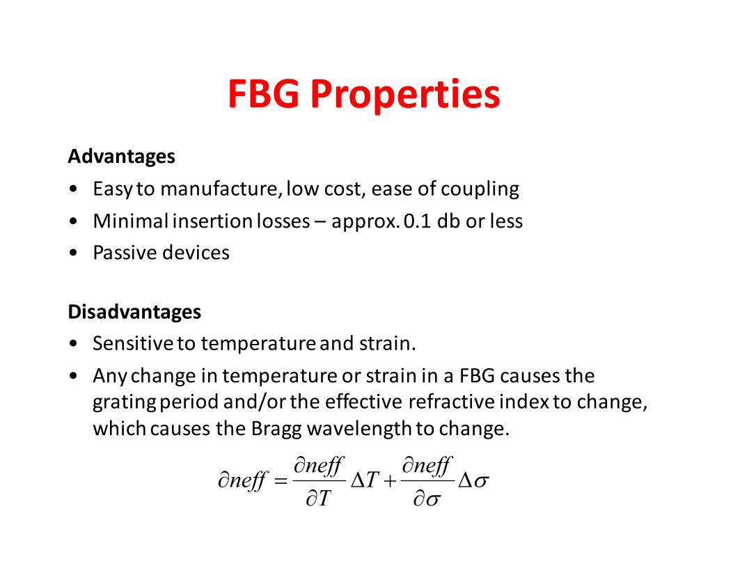
FBG Properties
Advantages
• Easy to manufacture, low cost, ease of coupling
• Minimal insertion losses – approx. 0.1 db or less
• Passive devices
Disadvantages
• Sensitive to temperature and strain.
• Any change in temperature or strain in a FBG causes the
grating period and/or the effective refractive index to change,
which causes the Bragg wavelength to change.
σσ
∆∂
∂+∆
∂
∂=∂
neffT
T
neffneff
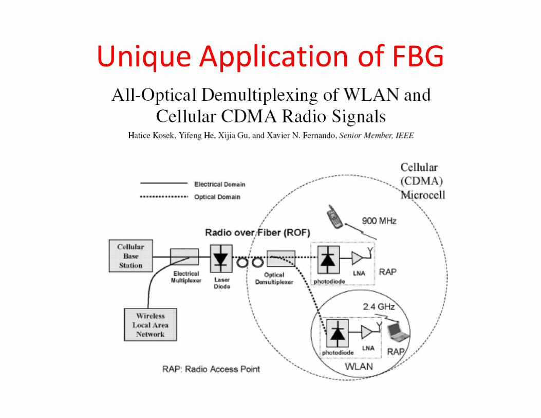
Unique Application of FBG
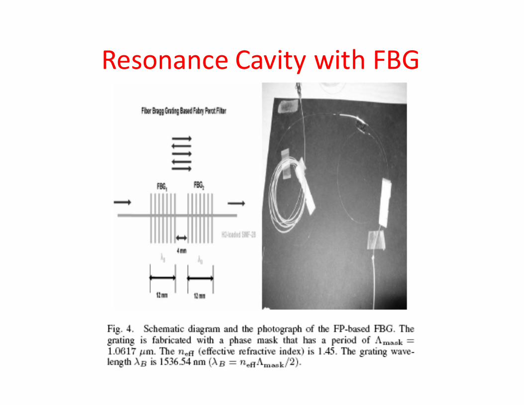
Resonance Cavity with FBG
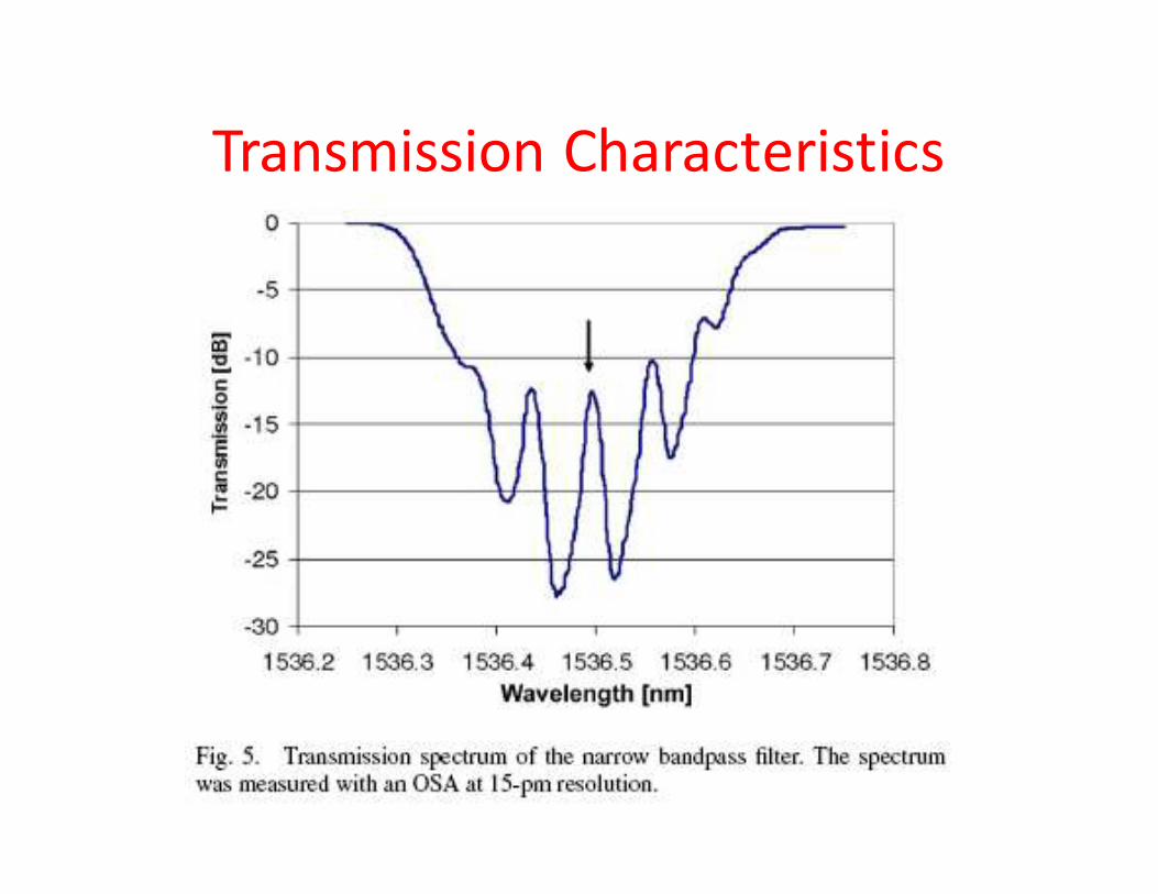
Transmission Characteristics
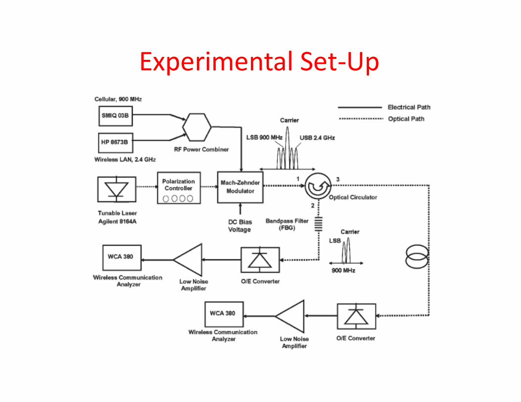
Experimental Set-Up
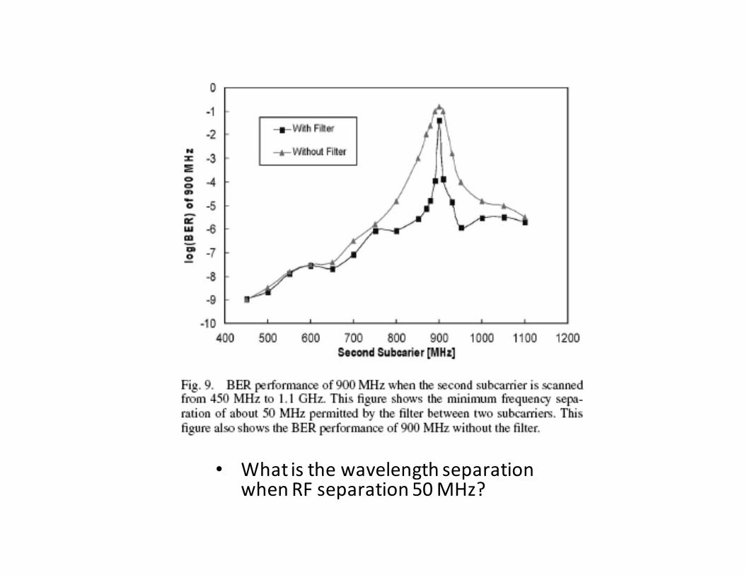
• What is the wavelength separation when RF separation 50 MHz?
Interferometers
Interferometer
An interferometric device uses 2 interfering paths of different lengths to resolve wavelengths
Typical configuration: two 3-dB directional couplers connected with 2 paths having different lengths
Applications:
— wideband filters (coarse WDM) that separate signals at1300 nm from those at 1550 nm
— narrowband filters: filter bandwidth depends on the number of cascades (i.e. the number of 3-dB couplers connected)
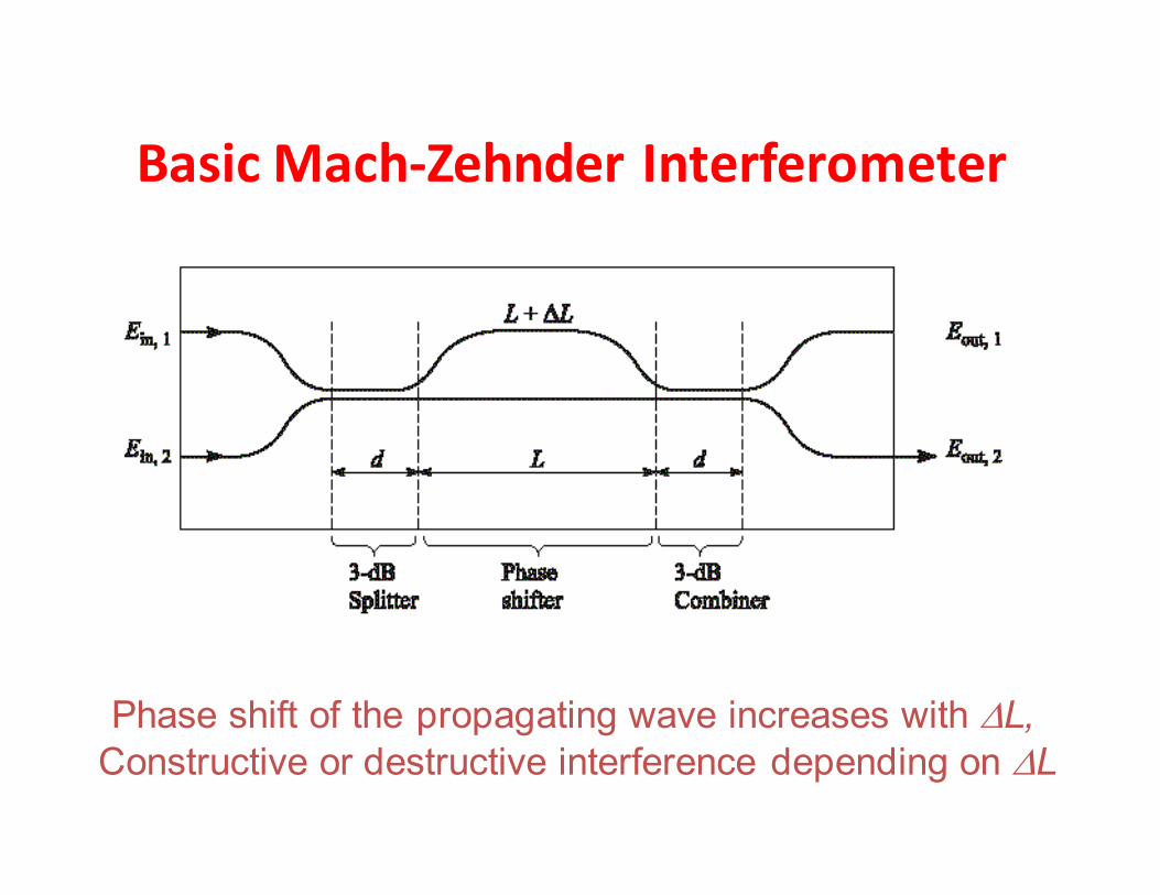
Basic Mach-Zehnder Interferometer
Phase shift of the propagating wave increases with ∆L, Constructive or destructive interference depending on ∆L
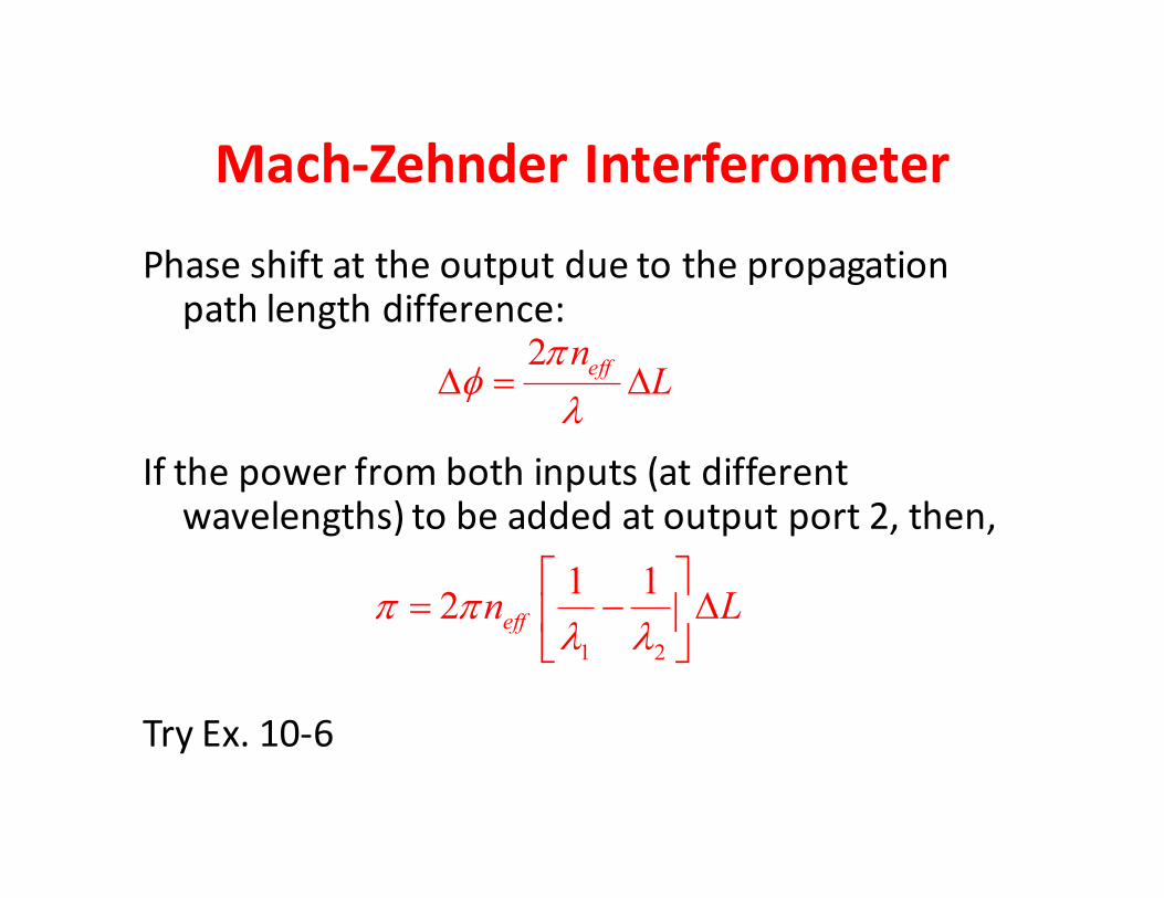
Mach-Zehnder Interferometer
Phase shift at the output due to the propagation path length difference:
If the power from both inputs (at different wavelengths) to be added at output port 2, then,
Try Ex. 10-6
1 2
1 12 effn Lπ π
λ λ
= − ∆
2effn
Lπ
φλ
∆ = ∆
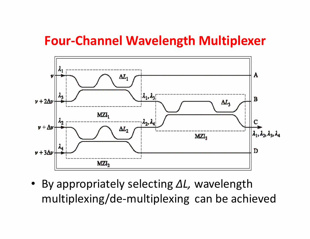
Four-Channel Wavelength Multiplexer
• By appropriately selecting ΔL, wavelength
multiplexing/de-multiplexing can be achieved
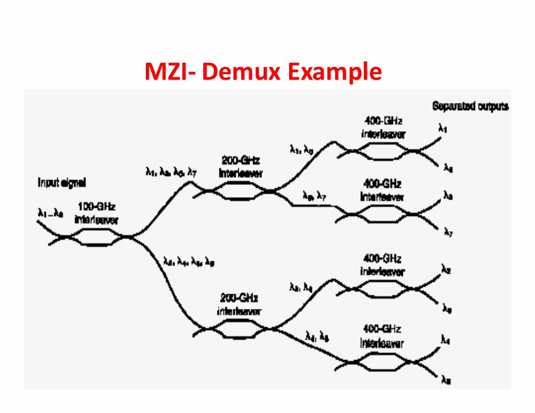
MZI- Demux Example
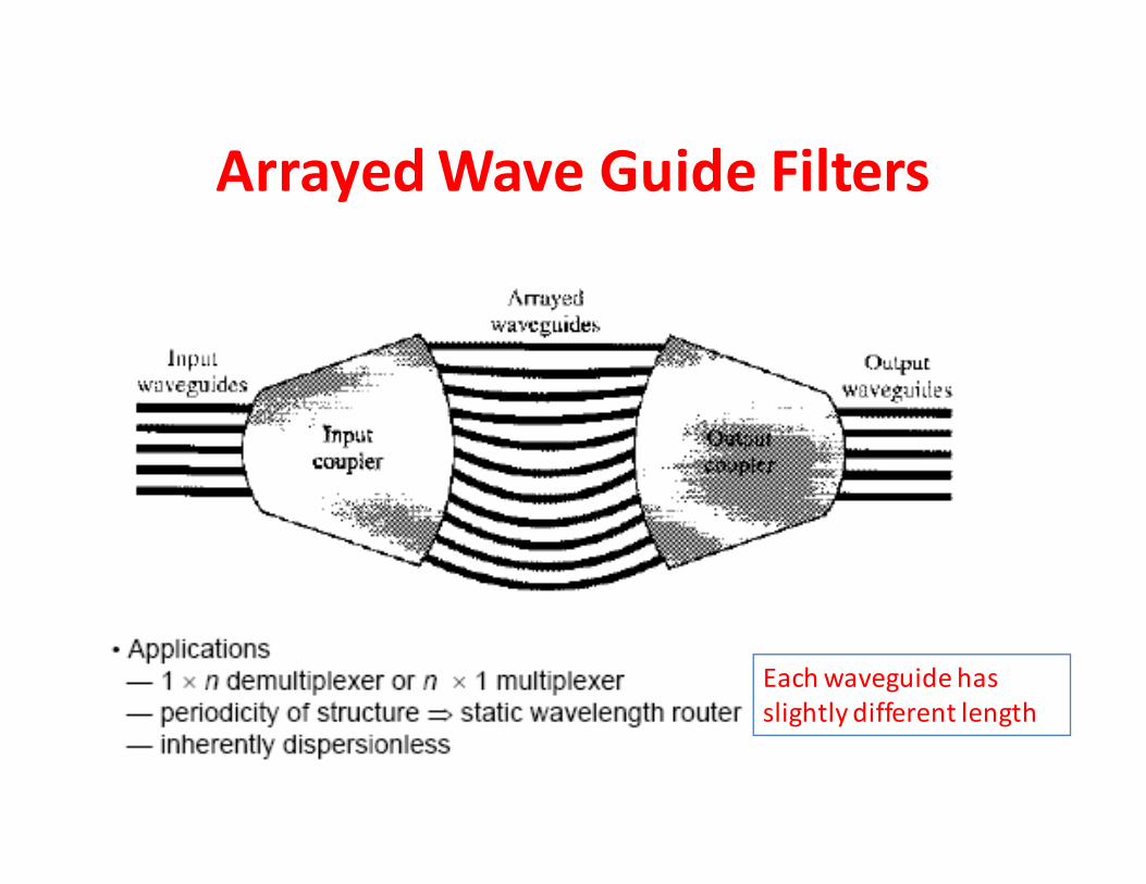
Arrayed Wave Guide Filters
Each waveguide has
slightly different length
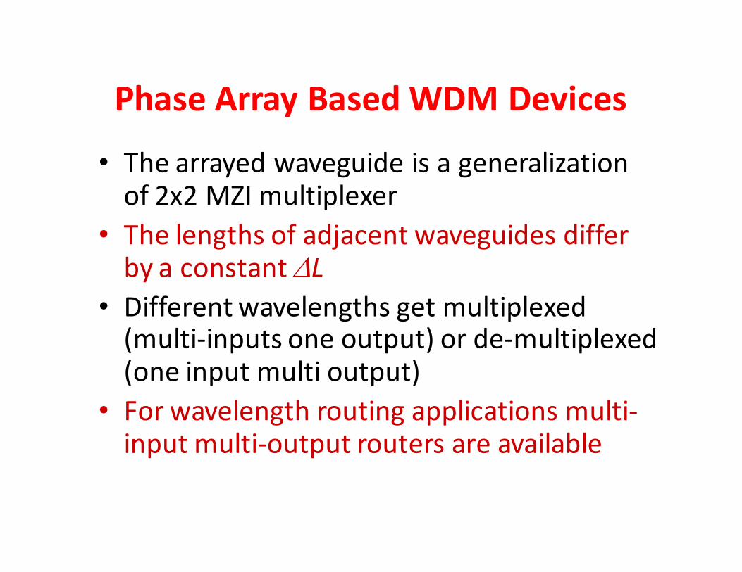
Phase Array Based WDM Devices
• The arrayed waveguide is a generalization of 2x2 MZI multiplexer
• The lengths of adjacent waveguides differ by a constant ∆L
• Different wavelengths get multiplexed (multi-inputs one output) or de-multiplexed (one input multi output)
• For wavelength routing applications multi-input multi-output routers are available
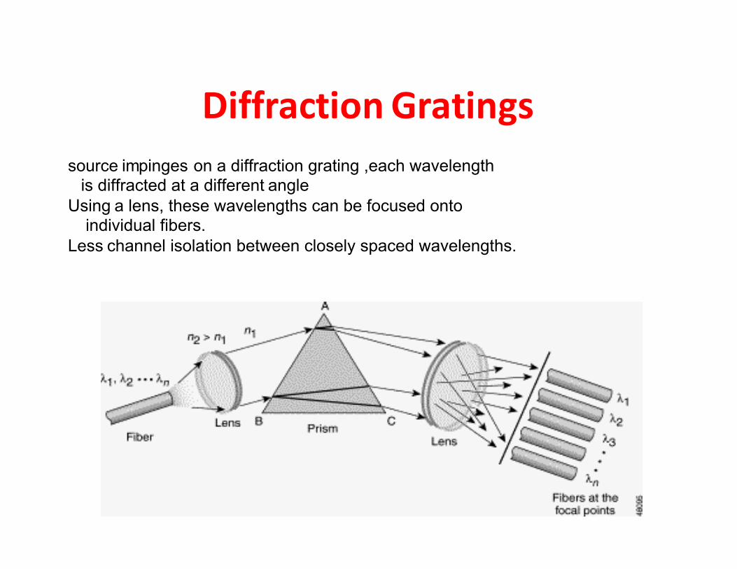
Diffraction Gratings
source impinges on a diffraction grating ,each wavelength is diffracted at a different angle
Using a lens, these wavelengths can be focused onto individual fibers.
Less channel isolation between closely spaced wavelengths.
Generating Multiple Wavelength for
WDM Networks
• Discrete DFB lasers
– Straight forward stable sources, but expensive
• Wavelength tunable DFB lasers
• Multi-wavelength laser array
– Integrated on the same substrate
–Multiple quantum wells for better optical and carrier confinement
• Spectral slicing – LED source and comb filters
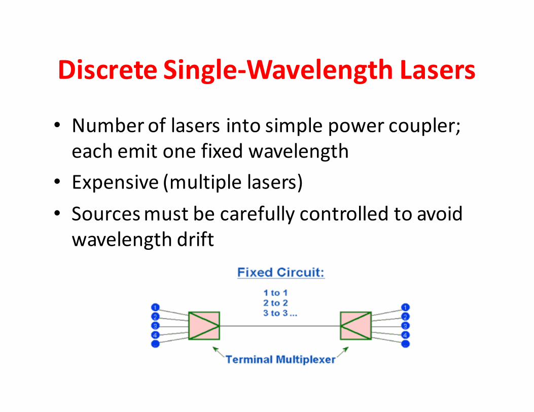
Discrete Single-Wavelength Lasers
• Number of lasers into simple power coupler;
each emit one fixed wavelength
• Expensive (multiple lasers)
• Sources must be carefully controlled to avoid
wavelength drift
Frequency Tuneable Laser
• Only one (DFB or DBR) laser that has grating
filter in the lasing cavity
• Wavelength is tuned by either changing the
temperature of the grating (0.1 nm/OC)
• Or by altering the injection current into the
passive section (0.006 nm/mA)
• The tuning range decreases with the optical
output power
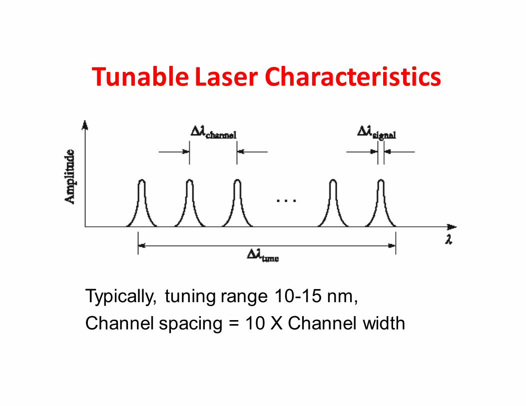
Tunable Laser Characteristics
Typically, tuning range 10-15 nm,
Channel spacing = 10 X Channel width

Tunable Filters
• Tunable filters are made by at least one branch of an interferometric filter has its – Propagation length or
– Refractive index altered by a control mechanism
• When these parameters change, phase of the propagating light wave changes (as a function of wavelength)
• Hence, intensity of the added signal changes (as a function of wavelength)
• As a result, wavelength selectivity is achieved
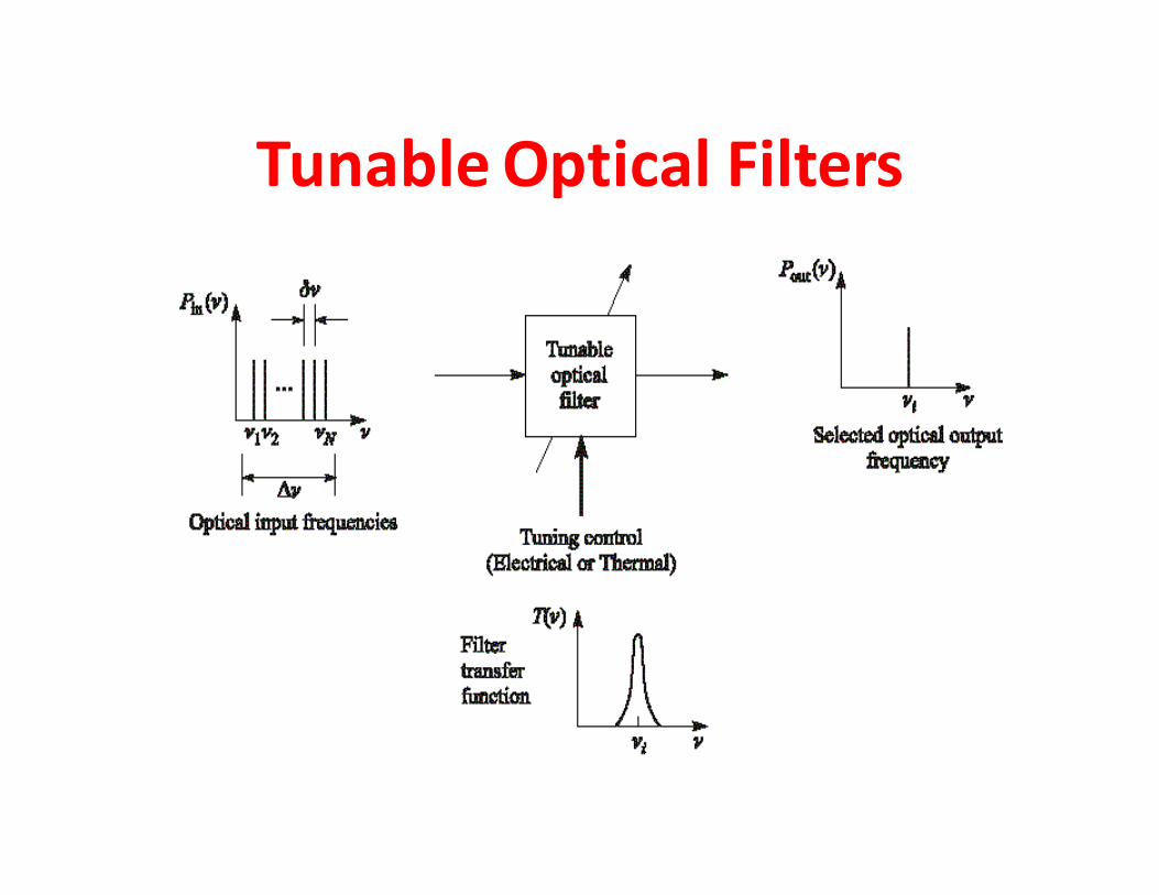
Tunable Optical Filters
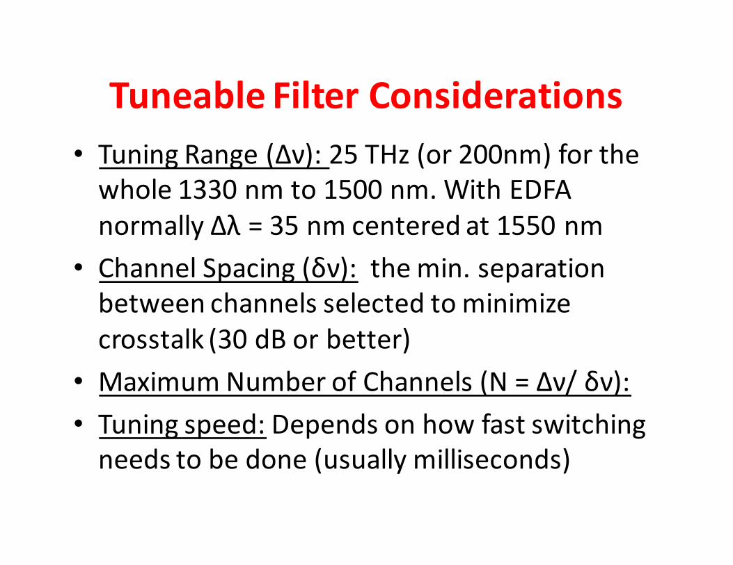
Tuneable Filter Considerations
• Tuning Range (Δν): 25 THz (or 200nm) for the
whole 1330 nm to 1500 nm. With EDFA
normally Δλ = 35 nm centered at 1550 nm
• Channel Spacing (δν): the min. separation
between channels selected to minimize
crosstalk (30 dB or better)
• Maximum Number of Channels (N = Δν/ δν):
• Tuning speed: Depends on how fast switching
needs to be done (usually milliseconds)
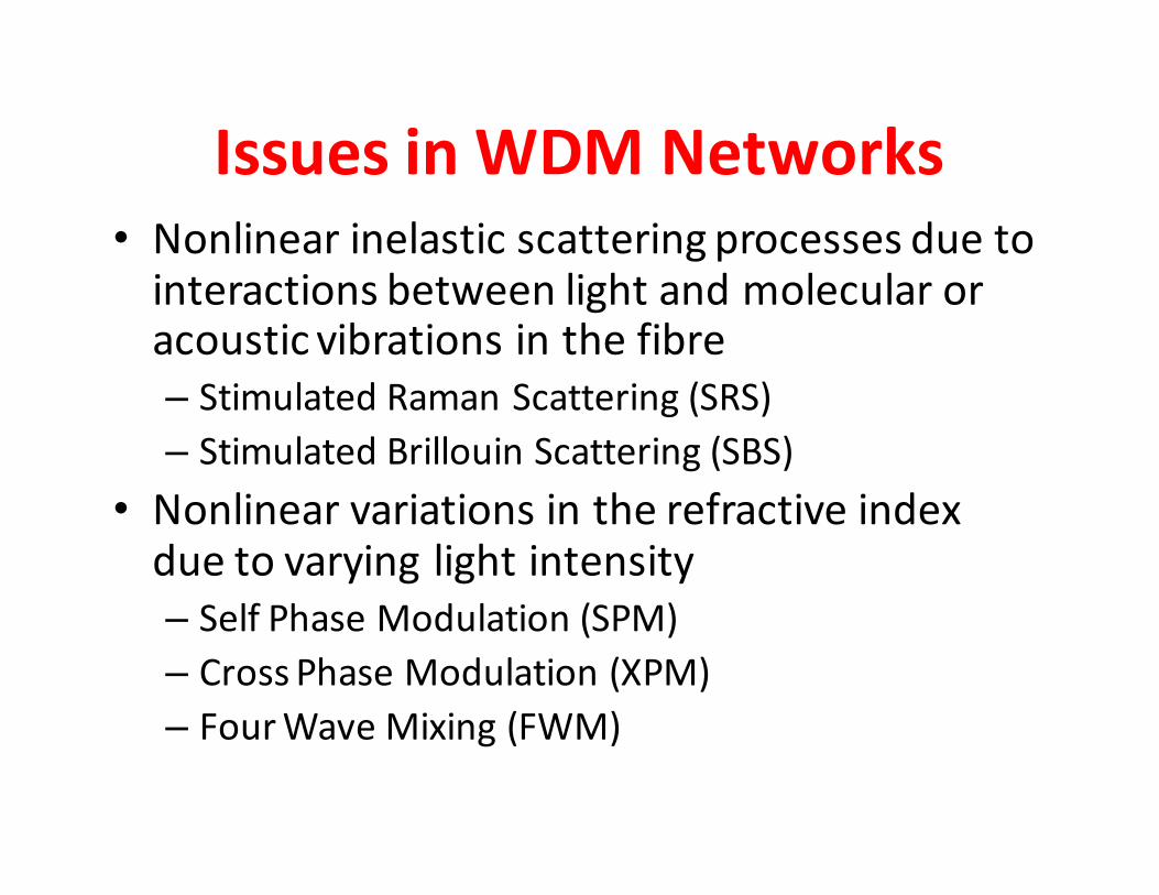
Issues in WDM Networks• Nonlinear inelastic scattering processes due to
interactions between light and molecular or acoustic vibrations in the fibre
– Stimulated Raman Scattering (SRS)
– Stimulated Brillouin Scattering (SBS)
• Nonlinear variations in the refractive index due to varying light intensity
– Self Phase Modulation (SPM)
– Cross Phase Modulation (XPM)
– Four Wave Mixing (FWM)
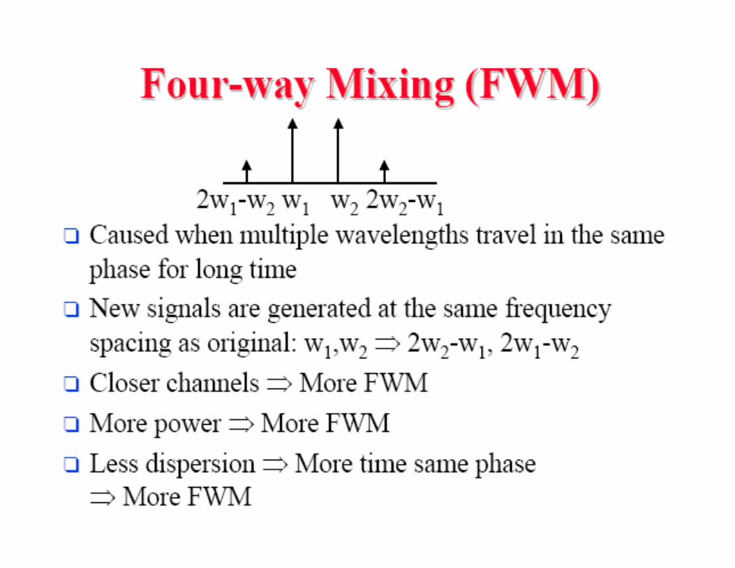
Summary• DWDM plays an important role in high capacity optical
networks
• Theoretically enormous capacity is possible
• Practically wavelength selective (optical signal
processing) components and nonlinear effects limit the
performance
• Passive signal processing elements like FBG, AWG are
attractive
• Optical amplifications is imperative to realize DWDM
networks