Embed Size (px)
Citation preview
Analog Dialogue 48-12 December 2014 1
Wearable Electronic Devices Monitor Vital Signs Activity Level and MoreHealth Monitoring Is Going Wearable
By Jan-Hein Broeders
When I was a little boy my mom always made sure that I had enough change to make a phone call in case of emergency Twenty years later mobile phones allowed us to make calls at any time and place After another 20 years of innovation the phone is no longer the key feature of our smart devices which can take beautiful pictures stream audio and video provide access to a wide variety of servicesmdashand are now becoming our personal trainers The devices loaded with sensors or connected to bodily worn sensors monitor day-to-day activity and personal health An increasing awareness of our health has fueled interest in measuring vital parametersmdashsuch as heart rate temperature oxygen saturation blood pressure activity level and calories burnedmdashand following their daily trends
Now a universal sensor front end with multiple sensors can monitor these parameters The biggest challenges are to minimize size and maximize battery lifetime This article discusses solutions for the rapidly growing market for wear-able electronics
The Most Important Vital SignWithout a heartbeat we would be in serious trouble so pulse or heart rate is by far the most important parameter to be mon-itored In addition to the number of beats per minute we want to check the behavior of the heart as a function of activity The rhythm is also important as rapidly changing heart rates are a sign of cardiac disease
Monitoring heart rate and heart activity is classically done by measuring biopotential with an electrocardiogram (ECG) Electrodes connected to the body measure signals caused by electric activity in the cardiac tissue This principle is used in professional diagnostic systems where up to 10 electrodes
analogcomanalogdialogue
can be connected to the chest and limbs ECGs provide detailed information regarding the various components (P- QRS- and T-wave) of one heartbeat
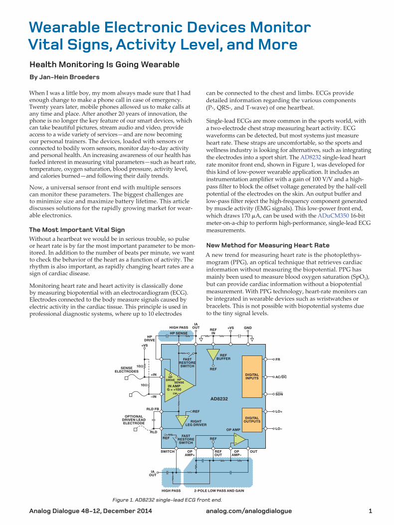
Single-lead ECGs are more common in the sports world with a two-electrode chest strap measuring heart activity ECG waveforms can be detected but most systems just measure heart rate These straps are uncomfortable so the sports and wellness industry is looking for alternatives such as integrating the electrodes into a sport shirt The AD8232 single-lead heart rate monitor front end shown in Figure 1 was developed for this kind of low-power wearable application It includes an instrumentation amplifier with a gain of 100 VV and a high-pass filter to block the offset voltage generated by the half-cell potential of the electrodes on the skin An output buffer and low-pass filter reject the high-frequency component generated by muscle activity (EMG signals) This low-power front end which draws 170 μA can be used with the ADuCM350 16-bit meter-on-a-chip to perform high-performance single-lead ECG measurements
New Method for Measuring Heart Rate
A new trend for measuring heart rate is the photoplethys-mogram (PPG) an optical technique that retrieves cardiac information without measuring the biopotential PPG has mainly been used to measure blood oxygen saturation (SpO2) but can provide cardiac information without a biopotential measurement With PPG technology heart-rate monitors can be integrated in wearable devices such as wristwatches or bracelets This is not possible with biopotential systems due to the tiny signal levels
HIGH PASSIA
OUTREFIN
REFBUFFER
AD8232
FASTRESTORESWITCH
IN AMPG = +100
CM
HPSENSE
HPDRIVE
REF
FR
ACDCDIGITALINPUTS
DIGITALOUTPUTS
OP AMP
OUTOPAMPndash
IAOUT
OPAMP+
SWITCH
OPTIONALDRIVEN LEADELECTRODE RIGHT
LEG DRIVER
SENSEELECTRODES
HPDRIVE
RLD
RLD FB
ndashIN
10
10
+IN
REF
REF
HIGH PASS 2-POLE LOW PASS AND GAIN
OUT
FASTRESTORESWITCH
REFREF
+VS
+VS
GND
HP SENSE
SDN
LO+
LOndash
Figure 1 AD8232 single-lead ECG front end
Analog Dialogue 48-12 December 20142
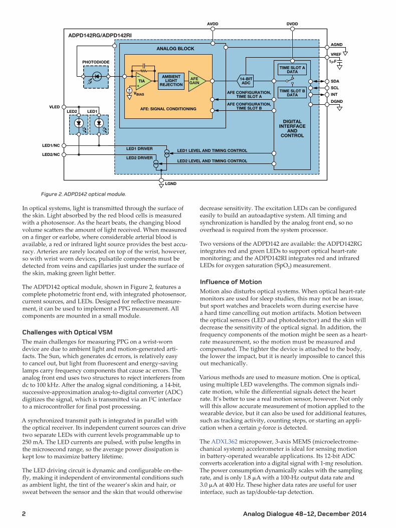
In optical systems light is transmitted through the surface of the skin Light absorbed by the red blood cells is measured with a photosensor As the heart beats the changing blood volume scatters the amount of light received When measured on a finger or earlobe where considerable arterial blood is available a red or infrared light source provides the best accu-racy Arteries are rarely located on top of the wrist however so with wrist worn devices pulsatile components must be detected from veins and capillaries just under the surface of the skin making green light better
The ADPD142 optical module shown in Figure 2 features a complete photometric front end with integrated photosensor current sources and LEDs Designed for reflective measure-ment it can be used to implement a PPG measurement All components are mounted in a small module
Challenges with Optical VSM
The main challenges for measuring PPG on a wrist-worn device are due to ambient light and motion-generated arti-facts The Sun which generates dc errors is relatively easy to cancel out but light from fluorescent and energy-saving lamps carry frequency components that cause ac errors The analog front end uses two structures to reject interferers from dc to 100 kHz After the analog signal conditioning a 14-bit successive-approximation analog-to-digital converter (ADC) digitizes the signal which is transmitted via an I2C interface to a microcontroller for final post processing
A synchronized transmit path is integrated in parallel with the optical receiver Its independent current sources can drive two separate LEDs with current levels programmable up to 250 mA The LED currents are pulsed with pulse lengths in the microsecond range so the average power dissipation is kept low to maximize battery lifetime
The LED driving circuit is dynamic and configurable on-the-fly making it independent of environmental conditions such as ambient light the tint of the wearerrsquos skin and hair or sweat between the sensor and the skin that would otherwise
decrease sensitivity The excitation LEDs can be configured easily to build an autoadaptive system All timing and synchronization is handled by the analog front end so no overhead is required from the system processor
Two versions of the ADPD142 are available the ADPD142RG integrates red and green LEDs to support optical heart-rate monitoring and the ADPD142RI integrates red and infrared LEDs for oxygen saturation (SpO2) measurement
Influence of Motion
Motion also disturbs optical systems When optical heart-rate monitors are used for sleep studies this may not be an issue but sport watches and bracelets worn during exercise have a hard time cancelling out motion artifacts Motion between the optical sensors (LED and photodetector) and the skin will decrease the sensitivity of the optical signal In addition the frequency components of the motion might be seen as a heart- rate measurement so the motion must be measured and compensated The tighter the device is attached to the body the lower the impact but it is nearly impossible to cancel this out mechanically
Various methods are used to measure motion One is optical using multiple LED wavelengths The common signals indi-cate motion while the differential signals detect the heart rate Itrsquos better to use a real motion sensor however Not only will this allow accurate measurement of motion applied to the wearable device but it can also be used for additional features such as tracking activity counting steps or starting an appli-cation when a certain g-force is detected
The ADXL362 micropower 3-axis MEMS (microelectrome-chanical system) accelerometer is ideal for sensing motion in battery-operated wearable applications Its 12-bit ADC converts acceleration into a digital signal with 1-mg resolution The power consumption dynamically scales with the sampling rate and is only 18 μA with a 100-Hz output data rate and 30 μA at 400 Hz These higher data rates are useful for user interface such as tapdouble-tap detection
LED2 LED1
LED1 DRIVER
LED2 DRIVER
TIA
VBIAS
AMBIENTLIGHT
REJECTION
AFE SIGNAL CONDITIONING
PHOTODIODE
ANALOG BLOCK
14-BITADC
TIME SLOT ADATA
TIME SLOT BDATA
DIGITALINTERFACE
ANDCONTROL
AFE CONFIGURATIONTIME SLOT A
AFE CONFIGURATIONTIME SLOT B
LED1 LEVEL AND TIMING CONTROL
LED2 LEVEL AND TIMING CONTROL
LGND
VLED
SDA
SCL
INT
DGND
AGND
VREF
1F
AVDD DVDD
LED1NC
LED2NC
ADPD142RGADPD142RI
AFEGAIN
Figure 2 ADPD142 optical module
Analog Dialogue 48-12 December 2014 3
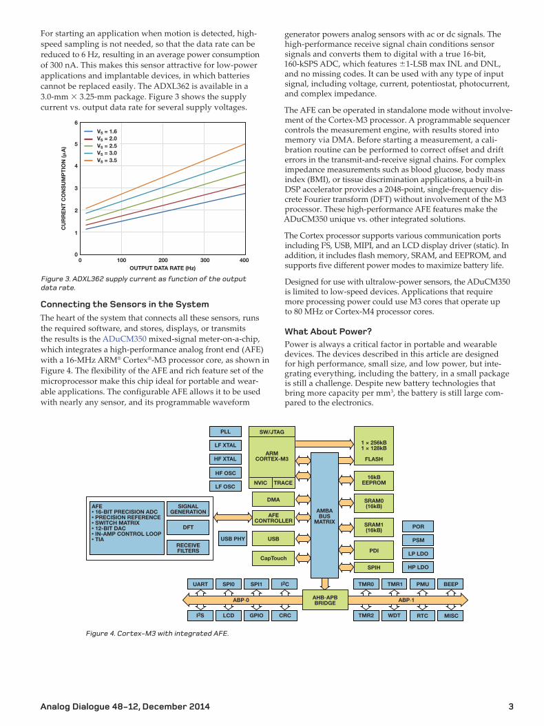
For starting an application when motion is detected high-speed sampling is not needed so that the data rate can be reduced to 6 Hz resulting in an average power consumption of 300 nA This makes this sensor attractive for low-power applications and implantable devices in which batteries cannot be replaced easily The ADXL362 is available in a 30-mm times 325-mm package Figure 3 shows the supply current vs output data rate for several supply voltages
6
5
4
3
2
1
00 100 200 300 400
OUTPUT DATA RATE (Hz)
CU
RR
EN
T C
ON
SU
MP
TIO
N (
A)
VS = 16VS = 20VS = 25VS = 30VS = 35
Figure 3 ADXL362 supply current as function of the output data rate
Connecting the Sensors in the System
The heart of the system that connects all these sensors runs the required software and stores displays or transmits the results is the ADuCM350 mixed-signal meter-on-a-chip which integrates a high-performance analog front end (AFE) with a 16-MHz ARMreg Cortexreg-M3 processor core as shown in Figure 4 The flexibility of the AFE and rich feature set of the microprocessor make this chip ideal for portable and wear-able applications The configurable AFE allows it to be used with nearly any sensor and its programmable waveform
generator powers analog sensors with ac or dc signals The high-performance receive signal chain conditions sensor signals and converts them to digital with a true 16-bit 160-kSPS ADC which features plusmn1-LSB max INL and DNL and no missing codes It can be used with any type of input signal including voltage current potentiostat photocurrent and complex impedance
The AFE can be operated in standalone mode without involve-ment of the Cortex-M3 processor A programmable sequencer controls the measurement engine with results stored into memory via DMA Before starting a measurement a cali-bration routine can be performed to correct offset and drift errors in the transmit-and-receive signal chains For complex impedance measurements such as blood glucose body mass index (BMI) or tissue discrimination applications a built-in DSP accelerator provides a 2048-point single-frequency dis-crete Fourier transform (DFT) without involvement of the M3 processor These high-performance AFE features make the ADuCM350 unique vs other integrated solutions
The Cortex processor supports various communication ports including I2S USB MIPI and an LCD display driver (static) In addition it includes flash memory SRAM and EEPROM and supports five different power modes to maximize battery life
Designed for use with ultralow-power sensors the ADuCM350 is limited to low-speed devices Applications that require more processing power could use M3 cores that operate up to 80 MHz or Cortex-M4 processor cores
What About Power
Power is always a critical factor in portable and wearable devices The devices described in this article are designed for high performance small size and low power but inte-grating everything including the battery in a small package is still a challenge Despite new battery technologies that bring more capacity per mm3 the battery is still large com-pared to the electronics
AHB-APBBRIDGE
LCD
TMR0 TMR1
WDTCRC
PMU
MISC
BEEP
ABP-1
TMR2 RTCGPIO
UART SPI0 SPI1 I2C
ABP-0
I2S
1 times 256kB1 times 128kB
FLASH
16kBEEPROM
SRAM1(16kB)
PDI
PLL
LF XTAL
HF OSC
LF OSC
HF XTAL
POR
PSM
HP LDO
CapTouchLP LDO
SPIH
AMBABUS
MATRIX
USB
DMA
NVIC TRACE
SWJTAG
ARMCORTEX-M3
SRAM0(16kB)
AFECONTROLLER
DFT
SIGNALGENERATION
AFEbull 16-BIT PRECISION ADCbull PRECISION REFERENCEbull SWITCH MATRIXbull 12-BIT DACbull IN-AMP CONTROL LOOPbull TIA
RECEIVEFILTERS
USB PHY
Figure 4 Cortex-M3 with integrated AFE
Analog Dialogue 48-12 December 20144
Housed in a tiny 3-mm times 3-mm package the chip is program-mable for use with various harvester sensors It draws 250-nA maximum quiescent current and works with almost any bat-tery technology from Li-Ion to thin-film batteries and super capacitors Integrated protection circuits ensure safe operation
Conclusion
This article describes some low-power products for wearable and personal health applications but this fast growing market is changing rapidly ADI technology can convert challenging problems into complete products and turnkey solutions Watch for more to come
References
wwwanalogcomhealthcare
Bioimpedance Circuit Design Challenges for Body-Worn Systems By Joseacute Carlos Conchell
Introduction
Wearable devices for vital-sign monitoring (VSM) are transforming the healthcare industry allowing us to mon-itor our vital signs and activity anytime anywhere The most relevant information about some of these key param-eters can be obtained by measuring body impedance
To be effective wearable devices must be small low cost and low power In addition measuring bioimpedance entails challenges related to the use of dry electrodes and safety requirements This article provides some solutions to these issues
Electrode Half-Cell Potential
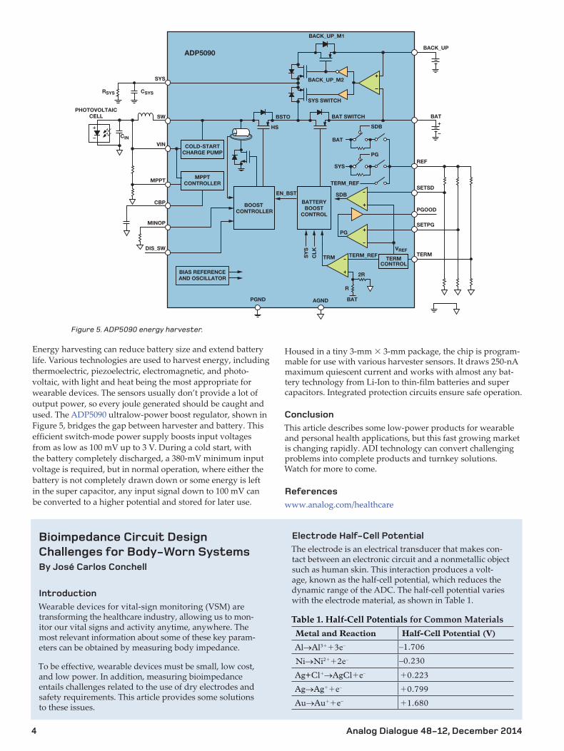
The electrode is an electrical transducer that makes con-tact between an electronic circuit and a nonmetallic object such as human skin This interaction produces a volt-age known as the half-cell potential which reduces the dynamic range of the ADC The half-cell potential varies with the electrode material as shown in Table 1
Table 1 Half-Cell Potentials for Common MaterialsMetal and Reaction Half-Cell Potential (V)
AlrarrAl3++3endash ndash1706
NirarrNi2++2endash ndash0230
Ag+Cl+rarrAgCl+endash +0223
AgrarrAg++endash +0799
AurarrAu++endash +1680
BAT+
ndash
BSTO
BACK_UP_M1
HS
BAT SWITCH
SYS SWITCH
BACK_UP_M2
BACK_UP
BAT
SYSREF
SETSD
PGOOD
SETPG
VREF
CIN
RSYS CSYS
TERM
SDB
PG
SY
S
CLK
TRM
TERM_REF
TERM_REF
EN_BST
SDB
SYS
SW
VIN
MPPT
CBP
DIS_SW
MINOP
+
ndash
PG
MPPTCONTROLLER
COLD-STARTCHARGE PUMP
PHOTOVOLTAICCELL
BOOST CONTROLLER
PGND
ADP5090
AGND BAT
R
2R
BATTERYBOOST
CONTROL
BIAS REFERENCEAND OSCILLATOR
TERMCONTROL
Figure 5 ADP5090 energy harvester
Energy harvesting can reduce battery size and extend battery life Various technologies are used to harvest energy including thermoelectric piezoelectric electromagnetic and photo-voltaic with light and heat being the most appropriate for wearable devices The sensors usually donrsquot provide a lot of output power so every joule generated should be caught and used The ADP5090 ultralow-power boost regulator shown in Figure 5 bridges the gap between harvester and battery This efficient switch-mode power supply boosts input voltages from as low as 100 mV up to 3 V During a cold start with the battery completely discharged a 380-mV minimum input voltage is required but in normal operation where either the battery is not completely drawn down or some energy is left in the super capacitor any input signal down to 100 mV can be converted to a higher potential and stored for later use
Analog Dialogue 48-12 December 2014 5
IEC 60601
IEC 60601 is a series of technical standards for the safety and effectiveness of medical electrical equipment pub-lished by the International Electrotechnical Commission It specifies 10 μA maximum dc-leakage current through the body under normal conditions and 50 μA maximum under worst-case single-fault conditions The maximum ac-leakage current depends on the excitation frequency If the frequency (fE) is less than or equal to 1 kHz the max-imum allowed current is 10 μA rms If the frequency is greater than 1 kHz the maximum allowed current is fE times 10 μA rms These patient current limits are
important circuit design parameters
Circuit Design Solution
The impedance measurement requires a voltagecurrent source and a currentvoltage meter so DACs and ADCs are commonly used A precision voltage reference and voltagecurrent control loops are essential and a microcon-troller is typically required to process data and obtain the real and imaginary parts of the impedance Additionally wearable devices are typically powered by a unipolar battery Finally integration of as many components as possible in a single package is very beneficial The ADuCM350 ultralow-power integrated mixed-signal meter-on-a-chip includes a Cortex-M3 processor and a hardware acceler-ator that can perform a single-frequency discrete Fourier transform (DFT) making it a powerful solution for wear-able devices
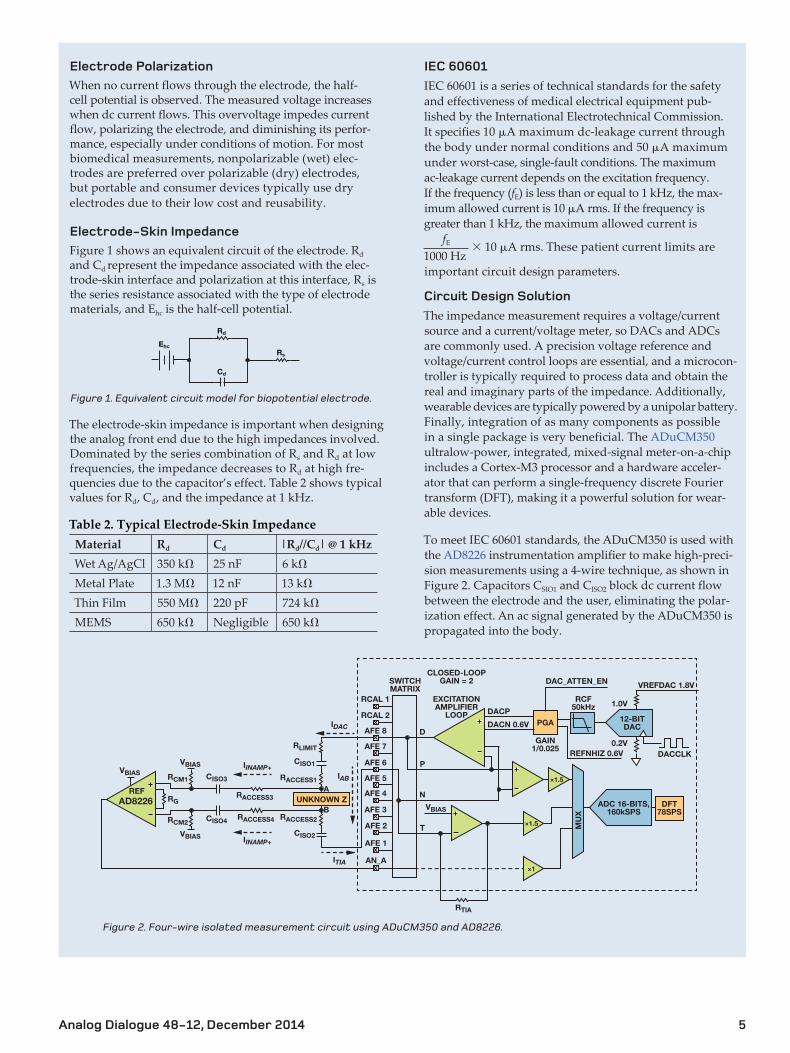
To meet IEC 60601 standards the ADuCM350 is used with the AD8226 instrumentation amplifier to make high-preci-sion measurements using a 4-wire technique as shown in Figure 2 Capacitors CSIO1 and CISO2 block dc current flow between the electrode and the user eliminating the polar-ization effect An ac signal generated by the ADuCM350 is propagated into the body
Electrode Polarization
When no current flows through the electrode the half- cell potential is observed The measured voltage increases when dc current flows This overvoltage impedes current flow polarizing the electrode and diminishing its perfor-mance especially under conditions of motion For most biomedical measurements nonpolarizable (wet) elec-trodes are preferred over polarizable (dry) electrodes but portable and consumer devices typically use dry electrodes due to their low cost and reusability
Electrode-Skin Impedance
Figure 1 shows an equivalent circuit of the electrode Rd and Cd represent the impedance associated with the elec-trode-skin interface and polarization at this interface Rs is the series resistance associated with the type of electrode materials and Ehc is the half-cell potential
Rd
Rs
Ehc
Cd
Figure 1 Equivalent circuit model for biopotential electrode
The electrode-skin impedance is important when designing the analog front end due to the high impedances involved Dominated by the series combination of Rs and Rd at low frequencies the impedance decreases to Rd at high fre-quencies due to the capacitorrsquos effect Table 2 shows typical values for Rd Cd and the impedance at 1 kHz
Table 2 Typical Electrode-Skin ImpedanceMaterial Rd Cd |RdCd| 1 kHzWet AgAgCl 350 kΩ 25 nF 6 kΩMetal Plate 13 MΩ 12 nF 13 kΩThin Film 550 MΩ 220 pF 724 kΩMEMS 650 kΩ Negligible 650 kΩ
1000 Hz
RCAL 1
AFE 1
AFE 2
AFE 3
AFE 4
AFE 5
AFE 6
AFE 7
AFE 8
SWITCHMATRIX
EXCITATIONAMPLIFIER
LOOP
CLOSED-LOOPGAIN = 2
D
P
N
T
RCAL 2PGA
GAIN10025
DACP
DACN 06V
REFNHIZ 06V
VBIAS
RTIA
RCF50kHz 10V
02V
12-BITDAC
ADC 16-BITS160kSPS
VREFDAC 18V
AN_A
DFT78SPS
times15
times15
times1
DACCLK
DAC_ATTEN_EN
MU
X
A
B
RLIMIT
RCM1
RCM2
RG
RACCESS1
RACCESS2
RACCESS3
IINAMP+
IINAMP+
IDAC
IAB
ITIA
RACCESS4
CISO1
CISO3
CISO4
CISO2VBIAS
VBIASVBIAS
AD8226REF
UNKNOWN Z
Figure 2 Four-wire isolated measurement circuit using ADuCM350 and AD8226
Analog Dialogue 48-12 December 20146
Capacitors CISO3 and CISO4 block the dc level from the ADC solving the half-cell potential problem and maintaining maximum dynamic range at all times CISO1 CISO2 CISO3 and CISO4 isolate the user ensuring zero dc current in normal mode and in the first case of failure and zero ac current in the first case of failure Finally resistor RLIMIT is designed to guarantee that the ac current in normal operation is below the limit RACCESS symbolizes the skin-electrode contact
The ADuCM350 measures the current from the tran-simpedance amplifier (TIA) and the output voltage of the AD8226 to calculate the unknown bodyimpedance RCM1 and RCM2 must be as high as possible to ensure that most of the current flows through the unknown impedance and the TIA The recommended value is 10 MΩ
Design Limitations
This design presents some limitations when the eletrode-skin impedance is close to 10 MΩ at the excitation fre-quency The electrode-skin impedance must be significantly smaller than RCM1 and RCM2 (10 MΩ) or VINAMP+ will not be equal to A and VINAMPndash will not be equal to B and the mea-surement accuracy will be degraded The electrode-skin impedance is typically much smaller than 1 MΩ when the excitation frequency is greater than 1 kHz as shown in Table 2
Validation
To prove the accuracy of this design the system was tested with different unknown impedances with the results compared to those measured by an Agilent 4294A impedance analyzer The magnitude error was less than plusmn1 in all the tests The absolute phase error was less than 1deg at 500 Hz and 5 kHz The 9deg phase offset error at 50 kHz could be corrected in software
Conclusion
Designs for battery-powered body-worn devices that measure bioimpedance must consider low power high SNR electrode polarization and IEC 60601 safety require-ments A solution using the ADuCM350 and AD8226 was described here Additional details including complete design equations can be found at wwwanalogcomlibraryanalogdialoguearchives48-12bio_imppdf
References
Neuman Michael R ldquoBiopotential ElectrodesrdquoThe Biomedi-cal Engineering Handbook Fourth Edition CRC Press 2015 Chi Mike Yu Tzyy-Ping Jung and Gert Cauwenberghs
ldquoDry-Contact and Noncontact Biopotential Electrodes Meth-odological Reviewrdquo IEEE Reviews in Biomedical Engineering Volume 3 2010 httpenwikipediaorgwikiIEC_60601
Joseacute Carlos Conchell [ joseconchellanalogcom] received his degree in electronic engineering from Universidad de Valencia Spain in 2010 then joined ADI as a system applications engineer in the Healthcare Group
Joseacute Carlos Conchell
Jan-Hein Broeders [janbroedersanalogcom] is ADIrsquos healthcare business development manager in Europe the Middle East and Africa Working closely with healthcare professionals he translates their present and future requirements into solutions Jan-Hein has more than 20 years of experience in the semiconductor industry He joined ADI as global FAE for Philips in 2005 and has been in his current role since 2008 He holds a bachelorrsquos degree in electrical engineering from the University of s-Hertogenbosch the Netherlands
Jan-Hein Broeders
Analog Dialogue 48-12 December 20142
In optical systems light is transmitted through the surface of the skin Light absorbed by the red blood cells is measured with a photosensor As the heart beats the changing blood volume scatters the amount of light received When measured on a finger or earlobe where considerable arterial blood is available a red or infrared light source provides the best accu-racy Arteries are rarely located on top of the wrist however so with wrist worn devices pulsatile components must be detected from veins and capillaries just under the surface of the skin making green light better
The ADPD142 optical module shown in Figure 2 features a complete photometric front end with integrated photosensor current sources and LEDs Designed for reflective measure-ment it can be used to implement a PPG measurement All components are mounted in a small module
Challenges with Optical VSM
The main challenges for measuring PPG on a wrist-worn device are due to ambient light and motion-generated arti-facts The Sun which generates dc errors is relatively easy to cancel out but light from fluorescent and energy-saving lamps carry frequency components that cause ac errors The analog front end uses two structures to reject interferers from dc to 100 kHz After the analog signal conditioning a 14-bit successive-approximation analog-to-digital converter (ADC) digitizes the signal which is transmitted via an I2C interface to a microcontroller for final post processing
A synchronized transmit path is integrated in parallel with the optical receiver Its independent current sources can drive two separate LEDs with current levels programmable up to 250 mA The LED currents are pulsed with pulse lengths in the microsecond range so the average power dissipation is kept low to maximize battery lifetime
The LED driving circuit is dynamic and configurable on-the-fly making it independent of environmental conditions such as ambient light the tint of the wearerrsquos skin and hair or sweat between the sensor and the skin that would otherwise
decrease sensitivity The excitation LEDs can be configured easily to build an autoadaptive system All timing and synchronization is handled by the analog front end so no overhead is required from the system processor
Two versions of the ADPD142 are available the ADPD142RG integrates red and green LEDs to support optical heart-rate monitoring and the ADPD142RI integrates red and infrared LEDs for oxygen saturation (SpO2) measurement
Influence of Motion
Motion also disturbs optical systems When optical heart-rate monitors are used for sleep studies this may not be an issue but sport watches and bracelets worn during exercise have a hard time cancelling out motion artifacts Motion between the optical sensors (LED and photodetector) and the skin will decrease the sensitivity of the optical signal In addition the frequency components of the motion might be seen as a heart- rate measurement so the motion must be measured and compensated The tighter the device is attached to the body the lower the impact but it is nearly impossible to cancel this out mechanically
Various methods are used to measure motion One is optical using multiple LED wavelengths The common signals indi-cate motion while the differential signals detect the heart rate Itrsquos better to use a real motion sensor however Not only will this allow accurate measurement of motion applied to the wearable device but it can also be used for additional features such as tracking activity counting steps or starting an appli-cation when a certain g-force is detected
The ADXL362 micropower 3-axis MEMS (microelectrome-chanical system) accelerometer is ideal for sensing motion in battery-operated wearable applications Its 12-bit ADC converts acceleration into a digital signal with 1-mg resolution The power consumption dynamically scales with the sampling rate and is only 18 μA with a 100-Hz output data rate and 30 μA at 400 Hz These higher data rates are useful for user interface such as tapdouble-tap detection
LED2 LED1
LED1 DRIVER
LED2 DRIVER
TIA
VBIAS
AMBIENTLIGHT
REJECTION
AFE SIGNAL CONDITIONING
PHOTODIODE
ANALOG BLOCK
14-BITADC
TIME SLOT ADATA
TIME SLOT BDATA
DIGITALINTERFACE
ANDCONTROL
AFE CONFIGURATIONTIME SLOT A
AFE CONFIGURATIONTIME SLOT B
LED1 LEVEL AND TIMING CONTROL
LED2 LEVEL AND TIMING CONTROL
LGND
VLED
SDA
SCL
INT
DGND
AGND
VREF
1F
AVDD DVDD
LED1NC
LED2NC
ADPD142RGADPD142RI
AFEGAIN
Figure 2 ADPD142 optical module
Analog Dialogue 48-12 December 2014 3
For starting an application when motion is detected high-speed sampling is not needed so that the data rate can be reduced to 6 Hz resulting in an average power consumption of 300 nA This makes this sensor attractive for low-power applications and implantable devices in which batteries cannot be replaced easily The ADXL362 is available in a 30-mm times 325-mm package Figure 3 shows the supply current vs output data rate for several supply voltages
6
5
4
3
2
1
00 100 200 300 400
OUTPUT DATA RATE (Hz)
CU
RR
EN
T C
ON
SU
MP
TIO
N (
A)
VS = 16VS = 20VS = 25VS = 30VS = 35
Figure 3 ADXL362 supply current as function of the output data rate
Connecting the Sensors in the System
The heart of the system that connects all these sensors runs the required software and stores displays or transmits the results is the ADuCM350 mixed-signal meter-on-a-chip which integrates a high-performance analog front end (AFE) with a 16-MHz ARMreg Cortexreg-M3 processor core as shown in Figure 4 The flexibility of the AFE and rich feature set of the microprocessor make this chip ideal for portable and wear-able applications The configurable AFE allows it to be used with nearly any sensor and its programmable waveform
generator powers analog sensors with ac or dc signals The high-performance receive signal chain conditions sensor signals and converts them to digital with a true 16-bit 160-kSPS ADC which features plusmn1-LSB max INL and DNL and no missing codes It can be used with any type of input signal including voltage current potentiostat photocurrent and complex impedance
The AFE can be operated in standalone mode without involve-ment of the Cortex-M3 processor A programmable sequencer controls the measurement engine with results stored into memory via DMA Before starting a measurement a cali-bration routine can be performed to correct offset and drift errors in the transmit-and-receive signal chains For complex impedance measurements such as blood glucose body mass index (BMI) or tissue discrimination applications a built-in DSP accelerator provides a 2048-point single-frequency dis-crete Fourier transform (DFT) without involvement of the M3 processor These high-performance AFE features make the ADuCM350 unique vs other integrated solutions
The Cortex processor supports various communication ports including I2S USB MIPI and an LCD display driver (static) In addition it includes flash memory SRAM and EEPROM and supports five different power modes to maximize battery life
Designed for use with ultralow-power sensors the ADuCM350 is limited to low-speed devices Applications that require more processing power could use M3 cores that operate up to 80 MHz or Cortex-M4 processor cores
What About Power
Power is always a critical factor in portable and wearable devices The devices described in this article are designed for high performance small size and low power but inte-grating everything including the battery in a small package is still a challenge Despite new battery technologies that bring more capacity per mm3 the battery is still large com-pared to the electronics
AHB-APBBRIDGE
LCD
TMR0 TMR1
WDTCRC
PMU
MISC
BEEP
ABP-1
TMR2 RTCGPIO
UART SPI0 SPI1 I2C
ABP-0
I2S
1 times 256kB1 times 128kB
FLASH
16kBEEPROM
SRAM1(16kB)
PDI
PLL
LF XTAL
HF OSC
LF OSC
HF XTAL
POR
PSM
HP LDO
CapTouchLP LDO
SPIH
AMBABUS
MATRIX
USB
DMA
NVIC TRACE
SWJTAG
ARMCORTEX-M3
SRAM0(16kB)
AFECONTROLLER
DFT
SIGNALGENERATION
AFEbull 16-BIT PRECISION ADCbull PRECISION REFERENCEbull SWITCH MATRIXbull 12-BIT DACbull IN-AMP CONTROL LOOPbull TIA
RECEIVEFILTERS
USB PHY
Figure 4 Cortex-M3 with integrated AFE
Analog Dialogue 48-12 December 20144
Housed in a tiny 3-mm times 3-mm package the chip is program-mable for use with various harvester sensors It draws 250-nA maximum quiescent current and works with almost any bat-tery technology from Li-Ion to thin-film batteries and super capacitors Integrated protection circuits ensure safe operation
Conclusion
This article describes some low-power products for wearable and personal health applications but this fast growing market is changing rapidly ADI technology can convert challenging problems into complete products and turnkey solutions Watch for more to come
References
wwwanalogcomhealthcare
Bioimpedance Circuit Design Challenges for Body-Worn Systems By Joseacute Carlos Conchell
Introduction
Wearable devices for vital-sign monitoring (VSM) are transforming the healthcare industry allowing us to mon-itor our vital signs and activity anytime anywhere The most relevant information about some of these key param-eters can be obtained by measuring body impedance
To be effective wearable devices must be small low cost and low power In addition measuring bioimpedance entails challenges related to the use of dry electrodes and safety requirements This article provides some solutions to these issues
Electrode Half-Cell Potential
The electrode is an electrical transducer that makes con-tact between an electronic circuit and a nonmetallic object such as human skin This interaction produces a volt-age known as the half-cell potential which reduces the dynamic range of the ADC The half-cell potential varies with the electrode material as shown in Table 1
Table 1 Half-Cell Potentials for Common MaterialsMetal and Reaction Half-Cell Potential (V)
AlrarrAl3++3endash ndash1706
NirarrNi2++2endash ndash0230
Ag+Cl+rarrAgCl+endash +0223
AgrarrAg++endash +0799
AurarrAu++endash +1680
BAT+
ndash
BSTO
BACK_UP_M1
HS
BAT SWITCH
SYS SWITCH
BACK_UP_M2
BACK_UP
BAT
SYSREF
SETSD
PGOOD
SETPG
VREF
CIN
RSYS CSYS
TERM
SDB
PG
SY
S
CLK
TRM
TERM_REF
TERM_REF
EN_BST
SDB
SYS
SW
VIN
MPPT
CBP
DIS_SW
MINOP
+
ndash
PG
MPPTCONTROLLER
COLD-STARTCHARGE PUMP
PHOTOVOLTAICCELL
BOOST CONTROLLER
PGND
ADP5090
AGND BAT
R
2R
BATTERYBOOST
CONTROL
BIAS REFERENCEAND OSCILLATOR
TERMCONTROL
Figure 5 ADP5090 energy harvester
Energy harvesting can reduce battery size and extend battery life Various technologies are used to harvest energy including thermoelectric piezoelectric electromagnetic and photo-voltaic with light and heat being the most appropriate for wearable devices The sensors usually donrsquot provide a lot of output power so every joule generated should be caught and used The ADP5090 ultralow-power boost regulator shown in Figure 5 bridges the gap between harvester and battery This efficient switch-mode power supply boosts input voltages from as low as 100 mV up to 3 V During a cold start with the battery completely discharged a 380-mV minimum input voltage is required but in normal operation where either the battery is not completely drawn down or some energy is left in the super capacitor any input signal down to 100 mV can be converted to a higher potential and stored for later use
Analog Dialogue 48-12 December 2014 5
IEC 60601
IEC 60601 is a series of technical standards for the safety and effectiveness of medical electrical equipment pub-lished by the International Electrotechnical Commission It specifies 10 μA maximum dc-leakage current through the body under normal conditions and 50 μA maximum under worst-case single-fault conditions The maximum ac-leakage current depends on the excitation frequency If the frequency (fE) is less than or equal to 1 kHz the max-imum allowed current is 10 μA rms If the frequency is greater than 1 kHz the maximum allowed current is fE times 10 μA rms These patient current limits are
important circuit design parameters
Circuit Design Solution
The impedance measurement requires a voltagecurrent source and a currentvoltage meter so DACs and ADCs are commonly used A precision voltage reference and voltagecurrent control loops are essential and a microcon-troller is typically required to process data and obtain the real and imaginary parts of the impedance Additionally wearable devices are typically powered by a unipolar battery Finally integration of as many components as possible in a single package is very beneficial The ADuCM350 ultralow-power integrated mixed-signal meter-on-a-chip includes a Cortex-M3 processor and a hardware acceler-ator that can perform a single-frequency discrete Fourier transform (DFT) making it a powerful solution for wear-able devices
To meet IEC 60601 standards the ADuCM350 is used with the AD8226 instrumentation amplifier to make high-preci-sion measurements using a 4-wire technique as shown in Figure 2 Capacitors CSIO1 and CISO2 block dc current flow between the electrode and the user eliminating the polar-ization effect An ac signal generated by the ADuCM350 is propagated into the body
Electrode Polarization
When no current flows through the electrode the half- cell potential is observed The measured voltage increases when dc current flows This overvoltage impedes current flow polarizing the electrode and diminishing its perfor-mance especially under conditions of motion For most biomedical measurements nonpolarizable (wet) elec-trodes are preferred over polarizable (dry) electrodes but portable and consumer devices typically use dry electrodes due to their low cost and reusability
Electrode-Skin Impedance
Figure 1 shows an equivalent circuit of the electrode Rd and Cd represent the impedance associated with the elec-trode-skin interface and polarization at this interface Rs is the series resistance associated with the type of electrode materials and Ehc is the half-cell potential
Rd
Rs
Ehc
Cd
Figure 1 Equivalent circuit model for biopotential electrode
The electrode-skin impedance is important when designing the analog front end due to the high impedances involved Dominated by the series combination of Rs and Rd at low frequencies the impedance decreases to Rd at high fre-quencies due to the capacitorrsquos effect Table 2 shows typical values for Rd Cd and the impedance at 1 kHz
Table 2 Typical Electrode-Skin ImpedanceMaterial Rd Cd |RdCd| 1 kHzWet AgAgCl 350 kΩ 25 nF 6 kΩMetal Plate 13 MΩ 12 nF 13 kΩThin Film 550 MΩ 220 pF 724 kΩMEMS 650 kΩ Negligible 650 kΩ
1000 Hz
RCAL 1
AFE 1
AFE 2
AFE 3
AFE 4
AFE 5
AFE 6
AFE 7
AFE 8
SWITCHMATRIX
EXCITATIONAMPLIFIER
LOOP
CLOSED-LOOPGAIN = 2
D
P
N
T
RCAL 2PGA
GAIN10025
DACP
DACN 06V
REFNHIZ 06V
VBIAS
RTIA
RCF50kHz 10V
02V
12-BITDAC
ADC 16-BITS160kSPS
VREFDAC 18V
AN_A
DFT78SPS
times15
times15
times1
DACCLK
DAC_ATTEN_EN
MU
X
A
B
RLIMIT
RCM1
RCM2
RG
RACCESS1
RACCESS2
RACCESS3
IINAMP+
IINAMP+
IDAC
IAB
ITIA
RACCESS4
CISO1
CISO3
CISO4
CISO2VBIAS
VBIASVBIAS
AD8226REF
UNKNOWN Z
Figure 2 Four-wire isolated measurement circuit using ADuCM350 and AD8226
Analog Dialogue 48-12 December 20146
Capacitors CISO3 and CISO4 block the dc level from the ADC solving the half-cell potential problem and maintaining maximum dynamic range at all times CISO1 CISO2 CISO3 and CISO4 isolate the user ensuring zero dc current in normal mode and in the first case of failure and zero ac current in the first case of failure Finally resistor RLIMIT is designed to guarantee that the ac current in normal operation is below the limit RACCESS symbolizes the skin-electrode contact
The ADuCM350 measures the current from the tran-simpedance amplifier (TIA) and the output voltage of the AD8226 to calculate the unknown bodyimpedance RCM1 and RCM2 must be as high as possible to ensure that most of the current flows through the unknown impedance and the TIA The recommended value is 10 MΩ
Design Limitations
This design presents some limitations when the eletrode-skin impedance is close to 10 MΩ at the excitation fre-quency The electrode-skin impedance must be significantly smaller than RCM1 and RCM2 (10 MΩ) or VINAMP+ will not be equal to A and VINAMPndash will not be equal to B and the mea-surement accuracy will be degraded The electrode-skin impedance is typically much smaller than 1 MΩ when the excitation frequency is greater than 1 kHz as shown in Table 2
Validation
To prove the accuracy of this design the system was tested with different unknown impedances with the results compared to those measured by an Agilent 4294A impedance analyzer The magnitude error was less than plusmn1 in all the tests The absolute phase error was less than 1deg at 500 Hz and 5 kHz The 9deg phase offset error at 50 kHz could be corrected in software
Conclusion
Designs for battery-powered body-worn devices that measure bioimpedance must consider low power high SNR electrode polarization and IEC 60601 safety require-ments A solution using the ADuCM350 and AD8226 was described here Additional details including complete design equations can be found at wwwanalogcomlibraryanalogdialoguearchives48-12bio_imppdf
References
Neuman Michael R ldquoBiopotential ElectrodesrdquoThe Biomedi-cal Engineering Handbook Fourth Edition CRC Press 2015 Chi Mike Yu Tzyy-Ping Jung and Gert Cauwenberghs
ldquoDry-Contact and Noncontact Biopotential Electrodes Meth-odological Reviewrdquo IEEE Reviews in Biomedical Engineering Volume 3 2010 httpenwikipediaorgwikiIEC_60601
Joseacute Carlos Conchell [ joseconchellanalogcom] received his degree in electronic engineering from Universidad de Valencia Spain in 2010 then joined ADI as a system applications engineer in the Healthcare Group
Joseacute Carlos Conchell
Jan-Hein Broeders [janbroedersanalogcom] is ADIrsquos healthcare business development manager in Europe the Middle East and Africa Working closely with healthcare professionals he translates their present and future requirements into solutions Jan-Hein has more than 20 years of experience in the semiconductor industry He joined ADI as global FAE for Philips in 2005 and has been in his current role since 2008 He holds a bachelorrsquos degree in electrical engineering from the University of s-Hertogenbosch the Netherlands
Jan-Hein Broeders