Embed Size (px)
Citation preview
IP-Enabled HD Surveillance Camera
Web Interface Operation
Manual
2
IP Camera Web Interface Manual
Important NotesIf this camera is hooked up to an NVR, either directly or through a network, we suggest that you perform all configuration for this camera from the recorder. This keeps all your camera configurations in one location.
The only capability you cannot set up at the NVR is smart motion detection. See “Smart Motion & NVRs” on page 62 for details on how to set this up with your NVR.
Motion Detection CompatibilityThe standard motion detection settings on the NVR and this camera are mutually exclusive; only one can be active at a time. If you set motion detection on your NVR and click Save, it disables any motion detection you set under Events in this camera (see “Events” on page 42). Likewise, if you click Save under Events on this camera, it disables the motion detection on the NVR.
The Events motion detection on this camera has separate day and night settings. If this is important to you, use the motion detection on this camera. If not, use motion detection on your NVR.
The smart motion settings on this camera (see “Smart Motion” on page 47) are compatible with standard motion settings on both the NVR and the camera. Use of Smart Events motion detection will not disable the standard settings on your NVR or camera.
We recommend that, when possible, smart motion be configured on your camera (of course), and all other motion detection be configured at your NVR.
Motion Detection Activation & Scheduling
When scheduling motion detection, the standard motion detection on the NVR and that set under Events on the camera are both covered by the motion detection schedule option.
Smart events from the camera are covered by the VCA schedule option.
The continuous schedule option covers both standard and smart motion detection.
3
IP Camera Web Interface Manual
Table of Contents
View PageIntroduction ..................................................................................... 4Overview of the Main Screen.......................................................... 5Camera Screen ................................................................................. 6Control Section ................................................................................ 7Camera Controls ............................................................................ 10Playback Controls .......................................................................... 12Timeline ......................................................................................... 14
Configuration PageConfiguration Page ........................................................................ 16Configure This Computer .............................................................. 17System Settings ............................................................................. 19Maintenance .................................................................................. 21Security .......................................................................................... 24User Management .......................................................................... 25Basic Network Settings.................................................................. 26Advanced Network Settings .......................................................... 30Video/Audio ................................................................................... 33Image.............................................................................................. 36Events ............................................................................................. 42Smart Motion ................................................................................. 47Storage Schedule ........................................................................... 50Storage Management ..................................................................... 52
Common ToolsArming Schedule ........................................................................... 54Linkage Method ............................................................................. 56
AppendicesDefault & Recommended Settings ................................................ 58Smart Motion & NVRs ................................................................... 62Troubleshooting............................................................................. 64User Parameters ............................................................................. 65Setting Up Email Alerts ................................................................ 66Support .......................................................................................... 71
4
IP Camera Web Interface Manual
IntroductionIf your system is connected to the Internet, you can access and control your system through a web-based interface. This makes it easy to check your cameras and control your system no matter where you are. As long as you have Internet service, you can access your system.
The web-based interface has three main pages: access, view, and configuration.
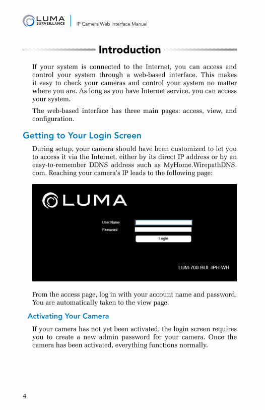
Getting to Your Login ScreenDuring setup, your camera should have been customized to let you to access it via the Internet, either by its direct IP address or by an easy-to-remember DDNS address such as MyHome.WirepathDNS.com. Reaching your camera’s IP leads to the following page:
From the access page, log in with your account name and password. You are automatically taken to the view page.
Activating Your Camera
If your camera has not yet been activated, the login screen requires you to create a new admin password for your camera. Once the camera has been activated, everything functions normally.
5
IP Camera Web Interface Manual
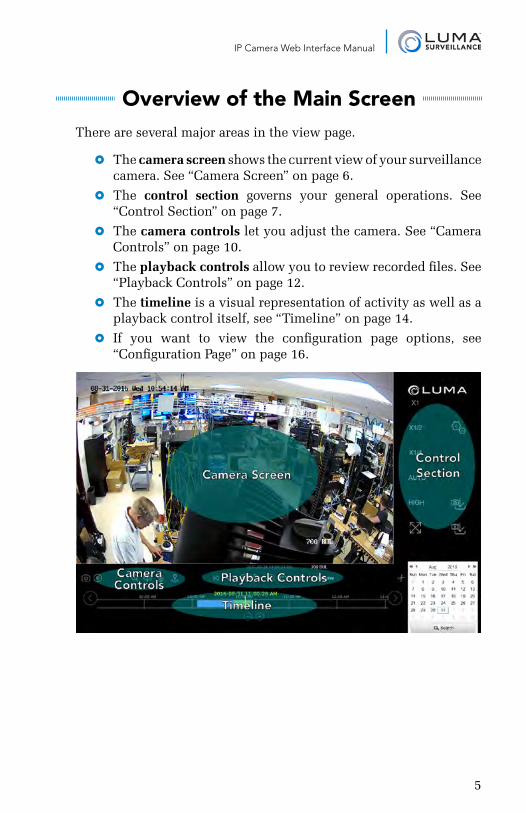
Overview of the Main ScreenThere are several major areas in the view page.
} The camera screen shows the current view of your surveillance camera. See “Camera Screen” on page 6.
} The control section governs your general operations. See “Control Section” on page 7.
} The camera controls let you adjust the camera. See “Camera Controls” on page 10.
} The playback controls allow you to review recorded files. See “Playback Controls” on page 12.
} The timeline is a visual representation of activity as well as a playback control itself, see “Timeline” on page 14.
} If you want to view the configuration page options, see “Configuration Page” on page 16.
6
IP Camera Web Interface Manual
Camera ScreenThis area shows the current view of your camera, complete with all of its OSD settings.
You cannot control the camera by interacting with the camera screen. Instead, use the Control Section to the right (see the facing page), or click the Playback button just below the camera name to open the timeline (see “Timeline” on page 14).
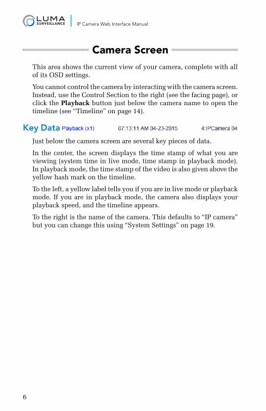
Key Data Just below the camera screen are several key pieces of data.
In the center, the screen displays the time stamp of what you are viewing (system time in live mode, time stamp in playback mode). In playback mode, the time stamp of the video is also given above the yellow hash mark on the timeline.
To the left, a yellow label tells you if you are in live mode or playback mode. If you are in playback mode, the camera also displays your playback speed, and the timeline appears.
To the right is the name of the camera. This defaults to “IP camera” but you can change this using “System Settings” on page 19.
7
IP Camera Web Interface Manual
Control SectionThis section handles the general operation of your camera. The icons are discussed here top to bottom, first the left column, then the right.
Image Scaling You can adjust the scale to change how much of the camera view is visible. The exact appearance of the screen depends on the browser window size, your monitor’s resolution, and the stream quality (see below). If the entire view is not visible, scroll bars appear to allow you to pan to the area you wish.
“Auto” is the default view, scaling the image to the available space in the browser, but does not preserve aspect ratio. X1 is the original, unscaled resolution, X1/2 is half scale, and X1/4 is quarter scale.
Clicking Auto adjusts the scaling to fit the camera screen to the browser window, distorting the image if necessary to maximize its size in your browser window.
The image scaling buttons are not available during playback.
Stream Quality This control shows the quality setting for the video stream. If the control reads “High,” then the camera stream is set at high resolution, and clicking this button switches it to medium resolution mode (and vice versa).
Full Screen Mode When clicked, this hides the various view page controls, and fills the screen with the camera’s view. Depending on your monitor’s aspect ratio, this may cause some image distortion.
To exit full-screen mode, left-click the mouse or press Esc.
Settings This takes you to the configuration page, from which you can adjust your camera’s settings or perform a variety of specialized commands. These commands are all explained under “Timeline” on page 14.
8
IP Camera Web Interface Manual
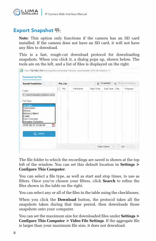
Export Snapshot Note: This option only functions if the camera has an SD card installed. If the camera does not have an SD card, it will not have any files to download.
This is a fast, rough-cut download protocol for downloading snapshots. When you click it, a dialog pops up, shown below. The tools are on the left, and a list of files is displayed on the right.
The file folder to which the recordings are saved is shown at the top left of the window. You can set this default location in Settings > Configure This Computer.
You can select a file type, as well as start and stop times, to use as filters. Once you’ve chosen your filters, click Search to refine the files shown in the table on the right.
You can select any or all of the files in the table using the checkboxes.
When you click the Download button, the protocol takes all the snapshots taken during that time period, then downloads those snapshots onto your computer.
You can set the maximum size for downloaded files under Settings > Configure This Computer > Video File Settings. If the aggregate file is larger than your maximum file size, it does not download.
9
IP Camera Web Interface Manual
Export Video Note: This option only functions if the camera has an SD card installed. If the camera does not have an SD card, it will not have any files to download.
This is a fast, rough-cut download protocol for downloading video. When you click it, a dialog pops up, shown at left. The tools are on the left, and a list of files is displayed on the right.
The file folder to which the recordings are saved is shown at the top left of the window. You can set this default location in Settings > Configure This Computer.
You can select a file type, as well as start and stop times, to use as filters. Once you’ve chosen your filters, click Search to refine the files shown in the table on the right.
You can select any or all of the files in the table using the checkboxes.
When you click the Download button, the protocol takes all the recordings taken during that time period. It clips longer recordings at the designated start and end time. Then the system downloads those files, one file for each event.
You can set the maximum size for downloaded files under Settings > Configure This Computer > Video File Settings. If a given file is larger than your maximum file size, the system splits the download into multiple files.
10
IP Camera Web Interface Manual
Camera ControlsThis set of five controls lets you manipulate your cameras.
Capture The leftmost button takes a screen grab of the camera’s view. The system saves it to your computer in the folder specified under Settings > Configure This Computer > Video File Settings (“Video File Settings” on page 18).
Record This button sets the active camera to record continuously. When you click the icon, it turns blue, indicating that it is active. Click it again to shut it off.
This takes priority over any scheduled activity, but does not actually change the camera’s schedule. The system saves it to your computer in the folder specified under Settings > Configure This Computer > Video File Settings (“Video File Settings” on page 18).
Zoom The zoom icon provides digital zoom for your camera.
When you click the icon, it turns blue, indicating that it is active. You then click and drag a rectangle in the camera view. The zoomed-in view remains active until you click the zoom icon off, or click on the camera’s screen. If the zoom rectangle is not the same aspect ratio of the camera (16:9), the zoomed-in image will be distorted.
Audio On This button lets you toggle whether or not you want to hear the audio stream from that camera or recording, if the camera has an associated microphone and you have speakers hooked up to your recorder or computer. When you click the icon, it turns blue, indicating that it is active. In addition, a volume slider appears.
While audio is active, hovering your mouse over the audio icon makes the volume slider reappear. Click the icon again to shut it off.
11
IP Camera Web Interface Manual
Microphone When you click the icon, it turns blue, indicating that it is active. Click it again to shut it off.
This opens an audio path from your computer’s default microphone to the audio output at the camera (for supported models only).
PTZ Controls The PTZ button opens an interface with which you can control the orientation and zoom of the selected camera. The interface appears over the control panel section of the view page.
The PTZ icon turns blue to remind you that it is active. Close the PTZ control panel by clicking the PTZ icon again.
Camera Controls
Note that only the 700 series cameras have motorized zoom and focus. Other Luma cameras have no capabilities that can be controlled from here.
In addition, the 700 series has only zoom and focus capability. They cannot be operated with any of the other PTZ controls here.
At the top right, the zoom controls let you zoom the camera in or out , adjusting your field of view.
In the center right, the focus controls let you adjust the visual feed. The button focuses the lens on objects close to the camera, and the button makes it focus on objects that are farther away.
12
IP Camera Web Interface Manual
Playback ControlsJust below the channel grid are playback controls that help you maneuver through your recordings. Note that if your camera is in live mode, the playback controls do not show. They only show when you are in playback mode.
You can control the playback of events, going either forward or backward. You can also click anywhere on the timeline to begin playback at that position.
Play/Pause This button starts the playback playing (or pauses it) in whichever direction is currently set, forward or backward.
Jump 15 Seconds These buttons jump the recording forward or backward roughly 15 seconds when in playback mode.
Play Forward/Backward When a recording is playing, you can use the play forward button to toggle playback speed. This varies from 1x–4x when using the web interface. The speed is shown in yellow above and to the left of the playback controls. You can also use the play backward button to play at 1x speed in reverse. There are no other speeds available in reverse-play mode.
When the recording has been paused, you can use the use the play forward button to toggle from 1/2x speed down to playback by frame. The speed is displayed in the yellow text. While in playback by frame mode, click on the channel view to advance the video by one captured frame. Note that if any frames were dropped during recording, the time stamp may jump farther than expected.
The play backward button has no effect when the playback is paused.
Next Event / Previous Event Clicking these buttons jumps you ahead to the start of the next event in the timeline, or back to the start of the event prior to the one you are watching.
13
IP Camera Web Interface Manual
Go to Live This button only appears in playback mode. Clicking it ends playback and returns you to real-time viewing.
Clip This button allows you to extract recordings from a desired span of time.
Click on the Clip button (it turns blue). Move your mouse over the timeline to wherever you want the extracted video to start. Note that as you move your mouse, a yellow time stamp appears above it, allowing you precision control over your start time. Click once to set your start time, then move your mouse to the right and click again to define the stop time.
Once the start and stop times are defined, the system opens up a download window between those times. Select the cameras you want, and it saves that clip for those selected cameras.
The files are saved to the download directory designated under Settings > Configure This Computer.
14
IP Camera Web Interface Manual
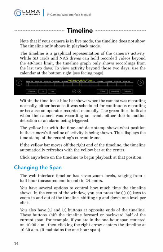
TimelineNote that if your camera is in live mode, the timeline does not show. The timeline only shows in playback mode.
The timeline is a graphical representation of the camera’s activity. While SD cards and NAS drives can hold recorded videos beyond the 48-hour limit, the timeline graph only shows recordings from the last two days. To view activity beyond those two days, use the calendar at the bottom right (see facing page).
Within the timeline, a blue bar shows when the camera was recording normally, either because it was scheduled for continuous recording or because an operator recorded manually. The green lines indicate when the camera was recording an event, either due to motion detection or an alarm being triggered.
The yellow bar with the time and date stamp shows what position in the camera’s timeline of activity is being shown. This displays the time stamp of the recording’s current frame.
If the yellow bar moves off the right end of the timeline, the timeline automatically refreshes with the yellow bar at the center.
Click anywhere on the timeline to begin playback at that position.
Changing the SpanThe web interface timeline has seven zoom levels, ranging from a half hour (measured end to end) to 24 hours.
You have several options to control how much time the timeline shows. In the center of the window, you can press the keys to zoom in and out of the timeline, shifting up and down one level per click.
You also have and buttons at opposite ends of the timeline. These buttons shift the timeline forward or backward half of the current span. For example, if you are in the one-hour span centered on 10:00 a.m., then clicking the right arrow centers the timeline at 10:30 a.m. (it maintains the one-hour span).
15
IP Camera Web Interface Manual
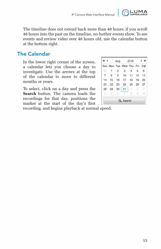
The timeline does not extend back more than 48 hours; if you scroll 48 hours into the past on the timeline, no further events show. To see events and review video over 48 hours old, use the calendar button at the bottom right.
The CalendarIn the lower right corner of the screen, a calendar lets you choose a day to investigate. Use the arrows at the top of the calendar to move to different months or years.
To select, click on a day and press the Search button. The camera loads the recordings for that day, positions the marker at the start of the day’s first recording, and begins playback at normal speed.
16
IP Camera Web Interface Manual
Configuration PageThis page has a number of menus on it, which give you complete control over camera. Where possible, use the NVR’s menus to control your camera to keep all configurations readily accessible.
Informational Elements
The upper right-hand corner of each of these pages shows your login account name and a logout button.
Just below them is a connection status notice. If you are connected to OvrC, you’ll see this icon: . If not, this icon says . If your cloud service is not connected, then the camera has a bad DNS setting. You can address this under Basic Network Settings > TCP/IP under the DNS Server settings (see “TCP/IP Tab” on page 26).
Logging OutWhen you are done, click Logout in the upper right-hand corner next to your account name, especially if you are on a shared computer.
Pro Tip: Do not “log out” just by closing the tab; certain browser settings might keep the session open even though the tab has been closed, which is a security and privacy risk.
17
IP Camera Web Interface Manual
Configure This ComputerThis defines the settings used by your computer when it accesses your camera over the web. Each computer has its own customized settings; they are stored locally on each computer. Because they are stored locally, these settings are used for any Luma system you access from that specific computer.
After adjusting your settings, click Save before switching to another window.
Live View ParametersHere you adjust the camera’s view.
Protocol
TCP checks the network connection state and favors preserving data. It places less importance on transmission speed. This can result in lag, but is more stable and reliable.
We strongly recommend TCP whenever remote access is required.
UDP favors sending data quickly. It places less importance on preserving data. It is faster than TCP, but should only be used with strong, reliable network connections.
We recommend UDP only on isolated networks and VLANs. Do not use UDP when remote access is required.
Multicast is required when using the multicast capability. Set up the multicast address under Basic Network Settings > TCP/IP.
We do not recommend using multicast if you can avoid it.
Play Performance
Shortest Delay sacrifices smoothness for immediacy. The view updates when a single frame has been buffered.
Auto gives you more smoothness at the expense of a little speed. This is our recommended setting.
Rules
If your browser can perform dynamic analysis for motion, you can enable those rules here. If you do, then, when motion is detected, green boxes will highlight areas where motion occurs.
18
IP Camera Web Interface Manual
Video File SettingsAt the top of this section, you can set your desired maximum video file size. When this size is exceeded, a new file is created to continue your recording.
The bottom two boxes specify where video files are saved when created or downloaded. These files are saved to the PC, not to a hard drive on the network. To change the file paths, click Browse and navigate to the folder you want.
Save recorded video to is the path for those files that you record manually from the view page, while accessing the system from this particular PC.
Save exported files to is the path for photos and videos that you fetch using the export tool.
Snapshot SettingsAt the top of this section, you can set the default format for snapshots.
The two boxes below that specify where to save snapshots when they are created or downloaded. These files are saved to the PC, not to a hard drive on the network. To change the file paths, click Browse and navigate to the folder you want.
Save snapshots from live view to is the path for those files that you record manually from the view page in live mode, while accessing the system from this PC.
Save snapshots from playback to is the path for photos that you take from the view page while watching saved footage.
19
IP Camera Web Interface Manual
System Settings
System Information TabThis presents data for your camera. This is where you look for its MAC address, firmware version, etc.
This table is for information only. Aside from the device name and number you cannot edit the details here.
Time Settings TabNOTE: If your camera is hooked to your NVR, it automatically syncs time with your NVR every five minutes, regardless of these settings.
This window lets you choose your time zone, decide how your system will maintain the time, and opt in or out of daylight saving time. After adjusting your time settings, click Save before switching to another menu.
Choose your time zone with the drop down menu at the top. North American time zones range from Hawaii (GMT-10:00) in the west to Newfoundland (GMT-03:30) in the east.
Next, choose either network time protocol (NTP) or manual time sync. This determines how your system checks to ensure that its time stamps remain accurate. Selecting one option deselects the other. We strongly recommend using NTP.
NTP
With NTP, your network pings the national server to synchronize to Coordinated Universal Time. This provides you with your most accurate time stamping. Using NTP requires Internet access.
There is no need to change any of the settings, unless you want to adjust the interval due to bandwidth or precision concerns.
Server Address: This is the site your camera pings for time stamps.
NTP Port: This port communicates with the time server.
Interval: This shows how often your camera checks for an update.
Manual Time Sync
With manual sync, your camera uses its internal clock. We do not recommend this setting because any electronic system’s internal
20
IP Camera Web Interface Manual
clock can drift. However, this choice is your only option if your network is not connected to the Internet.
Device Time shows the current time setting of the camera. It cannot be edited here.
Set Time lets you specify a time that you want to use. As soon as you press OK, the camera resets to that time.
Alternatively, you can click Sync with computer time. When you click the checkbox, the camera communicates with the network computer and adjusts its time to match. Although the box remains checked, this synchronization happens only once (the box becomes unchecked when you leave this screen).
DST
The daylight saving time (DST) tool works with both NTP and manual time settings.
By default, daylight saving time is enabled. If your location does not observe daylight saving time, click Enable DST to remove the check mark and disable DST adjustment.
The Start Time and End Time boxes set the month, week, day, and hour (in 24-hour time) that daylight saving time starts and ends.
NOTE: You are not setting the day and date with this tool. Instead, you are selecting (for example) the second Sunday in March.
The DST Offset drop-down sets the amount that the time changes.
As of 2016 in the most of the US and Canada, you can keep the default settings.
Places that do not observe daylight saving time include Arizona (outside of Navajo territory), Hawaii, Saskatchewan, and a number of local exceptions across Canada. For Arizona and Hawaii, disable DST. For Saskatchewan, disable DST and set your system to Central Time. For other exceptions, check local regulations.
Hardware Settings TabThis tab lets you activate the camera’s infrared light. We recommend doing so.
Click Save when finished.
21
IP Camera Web Interface Manual
Maintenance
Maintenance TabThese commands all keep your camera running smoothly.
Basic Operations
Reboot restarts the camera. This may be necessary if you’ve had an outage and your recorder can’t locate it over the network.
Restore reverts the camera to its default values and settings, however it keeps the data required for network settings and user accounts. This command does not remove recordings from the SD card.
Default clears all your settings and returns the unit to its factory status. This renders the camera inactive; you must activate it again to resume use. This command does not remove recordings from the SD card.
Configuration File
The next set of controls allow you to move configuration files between systems.
NOTE: To avoid unintended errors, config files are only transferable between same-model cameras with the matching firmware versions.
Export Configuration copies the XML of your camera’s configuration to a location of your choice. To export a config file, click Export and use the file-saving dialog.
Import Configuration applies an existing XML configuration file to your camera. Click Browse and use the standard navigation dialog to locate the desired file. Once you’ve located it, its path shows in the text box. Press Import. The progress of the upload shows below the text box.
Pro Tip: Export your configuration settings before making any changes. It is a very useful backup tool; if you keep an archive of dated configuration files, it will be easy to restore your camera whenever it’s needed.
Update
This section lets you update your system to the latest firmware without having to be physically at your device.
22
IP Camera Web Interface Manual
You must first download the new firmware to your computer. You cannot update your system directly from the Luma website.
Once you have downloaded the firmware to your local computer, click Browse and navigate to it. Once you have selected the firmware file, its path shows in the text box. Be sure to select the proper file; nothing prevents you from updating to an older file.
Click Update. While you are updating, the camera locks you out of navigating the configuration menus. You can track the update status just below the text box. Once the update reaches 100%, the camera reboots (you should see the word Rebooting appear near the center of your screen). When it has finished rebooting, you can resume operations.
During an update, if you click on the view page, the update aborts and the system returns to normal operation. If the update hangs for some reason, the update gets safely aborted but the system does not automatically unlock the configuration page. Just click over to the view page to resume operations.
Log TabNOTE: The camera can only keep a log if equipped with an SD card or attached to a network drive.
This section provides an easily accessed list of events as recorded by your camera. The list is initially blank, and remains so until you execute a search.
The columns in this list give, in order:
#: An arbitrary number assigned by the system.
Time: The time stamp showing when the event began.
Major Type: The broad category of event.
Minor Type: The specific subtype of the major type of event listed.
Channel: The channel number of the camera involved. If no camera was involved, this remains blank.
Local/Remote User: This gives the account name used to access the camera.
Remote Host IP: If the system as accessed remotely, this shows the IP address of the user’s computer.
If there are a lot of event results shown, you can use the page
23
IP Camera Web Interface Manual
navigation controls at the bottom to access events not shown.
Filtering the List
At the top of the screen, you can set filters to search for the sorts of events you want to look at. You can select one of the Major Types using the drop-down menu, or choose to view all event types.
Once you have selected a major type, you can select a specific operation from the Minor Type drop-down menu.
Below those, you can select the start and stop time for your search. When you click on one of these, it opens a pop-up with a calendar on top, and a time stamp at the bottom. You can click on any date to select it.
To set the time, you can click on the hour, minute, or second entry to set it. Hours are given in 24-hour time. Minutes and seconds are provided in increments of 5, but when one of these is selected, you can also adjust them up and down by one by using the arrows at the right side of the time display.
You can also use the Quick Selection button at the bottom left to make a time grab from the last minute in 15-second intervals with a single click.
Press OK or click away from the dialog to accept your selection.
Once you have set all your parameters, click Search to apply the filters.
If you press Export, the current log of events is saved directly to your PC. This opens a standard file-saving dialog box for your system.
24
IP Camera Web Interface Manual
SecurityThis menu protects your system from being accessed by outsiders.
Authentication TabRTSP Authentication: RTSP streams live video to multiple external devices, all from one common DDNS address. RTSP creates one-to-one connections; remote devices must request the stream and be admitted. Use basic configuration unless your third-party system requires that it be disabled.
Enable SSH: Secure socket handling allows you to use a command line interface to access the camera. We recommend you disable this feature. It has been removed from recent firmware revisions.
Enable Illegal Login Lock: This blocks an IP from accessing the camera if it has too many failed login attempts. An admin login is blocked after seven failed attempts; an operator is blocked after five. The lockout lasts 30 minutes. If needed, you can power the camera down to reset the lockout.
IP Address Filter TabThis lets you block or permit specific IP addresses from your system. The chart shows all filters currently active for the camera.
Click Enable IP Address Filter to use this capability.
From the dropdown menu, select Allowed to view whitelisted addresses, or Blocked to view blacklisted them.
Click Add to create a new IP address to block. Modify lets you change it if you made a typo.
To remove IP addresses from the list, select the desired addresses using the checkboxes to the left. When you click Delete, the camera deletes all currently selected IP addresses from the filter.
25
IP Camera Web Interface Manual
User ManagementThis menu lets you add, edit, or remove users from the system.
When using this camera as a plug-and-play device in a Luma NVR, do not change password for the admin account on this camera. After successfully connecting the camera to the NVR, you can use the PoE Password function on the NVR to change the password to the admin account on this camera.
Adding a User
Click the Add button. This opens the dialog shown below.
Enter the new account’s user name. Account names can be up to 32 characters long, and can contain numbers and letters. It cannot contains spaces, dashes, or underscores. We recommend that you add accounts by individual users’ names (e.g., JohnSmith) rather than use a collective account.
Choose the account’s level. There are two levels for users: operator and user. The only difference between them is the default permissions they are given (see “Troubleshooting” on page 64 for details). However, an admin (only) can use the checkboxes to customize permissions for each account individually.
Enter the user’s password. It can be up to 16 characters long. To ensure compatibility with the NVR’s local interface, passwords can only contain numbers, letters, spaces, and the following special characters: . - _: / @ , ? ! ‘ ; ( ) $ & “ [ ] { } # % ^ * + = \ | ~ < > `
Pro Tip: Most hacks come from robot programs, so use a password that is long and easy to remember. A password like parisinthespring is more secure and easier to remember than P4S$w*rD.
Click OK to save the new user, or Back to cancel creating that user.
Editing a User
Click on the desired account in the table of users, then click Modify. All controls are the same as for adding a user. You cannot change anything about the admin account other than its password.
Deleting a User
Click on an account in the table, then click Delete. There is no undo.
26
IP Camera Web Interface Manual
Basic Network SettingsNote: If you are attaching this camera to a Luma NVR as a plug-and-play, leave these settings at their default!
Important: You must reboot the camera for network setting changes to take effect.
If you make changes, click Save before switching to a different menu.
TCP/IP TabIf you are using this camera with a Luma NVR, be aware that the NVR will set an IP address for the camera based on the camera internal NIC setting.
NIC Type: If you are connecting this camera to an older, slower network, you can customize the interface to minimize the bandwidth use if needed. We recommend leaving this set to Auto, which identifies your system and adjusts operation automatically.
DHCP: Clicking this enables your network to assign IP addresses as needed to link with other IP devices. While DHCP is active, most of the boxes on this page are deactivated, as they may be changed by the system as needed. Once the camera is linked, deselect this box to ensure the camera has an unchanging IP address. This allows you to use the web interface and mobile utility to access your system.
IPv4 Address: This is the IP address of your camera, which is needed to allow you to access the system remotely, and to use the Luma mobile application. If you will be accessing your system remotely, be sure to deselect DHCP. You cannot use the Internet to access your system if DHCP is enabled. Pressing the Test button (to the right) pings the address to ensure it is not already in use.
IPv4 Subnet Mask: If you need to edit this to connect to your network, contact your IT administrator.
IPv4 Default Gateway: This holds the address of your router, once the camera has found the router and established a connection.
IPv6 Mode: This dropdown lets you choose whether you determine the IPv6 address manually, let the router assign it using DHCP, or use route advertisement. If route advertisement has been selected, pressing the View Route Advertisement button displays a pop-up with that information.
27
IP Camera Web Interface Manual
IPv6 Address: This is the address of your device, and can only be changed if your IPv6 mode is set to manual. Consult with your IT administrator for the proper setting.
IPv6 Subnet Mask: This entry can only be changed if your IPv6 mode is set to manual. If you need to edit this to connect to your network, consult with your IT administrator for the proper setting.
IPv6 Default Gateway: This entry can only be changed if your IPv6 mode is manual (check with your IT administrator if needed). It will display your router’s address if your router is IPv6 capable.
MTU: This entry displays the largest packet of data the unit is allowed to send. There is no need to change it unless your network requires a specific packet size as determined by the IT admin.
Multicast Address: This is the group address to which your camera sends the multicast stream. Users can then request a copy of the stream. Be sure that you set the protocol to multicast under Configure This Computer.
Enable Multicast Discovery: Enabling this starts the camera streaming its signal via multicast.
DNS Server
Preferred DNS Server: These is where your system looks to convert a URL to an IP address. Generally, this should be your router (see IPv4 Default Gateway, above); contact your IT admin for details.
Alternate DNS Server: These is the second place that your system looks to convert a URL to an IP address. Contact your IT admin for details.
DDNS TabThis allows you to connect to your surveillance system from anywhere, via the Internet, using a web address that’s easy to remember.
Click the box labeled Enable DDNS, then choose a type from the DDNS Type menu. Next, choose a server address. We recommend WirepathDDNS and ns2.wirepathdns.com.
Enter your desired domain in the Domain box. This creates a personalized server address, which is shown under Device URL at the bottom. If someone has already registered your desired domain, the system adds a unique ID (typically a few digits) to your domain.
28
IP Camera Web Interface Manual
If you do not like these digits, try another domain or server address.
Example: If you choose the domain SmithCamera, your camera’s URL would be SmithCamera.WirepathDNS.com. If someone else has already claimed SmithCamera, then your URL would be something like SmithCamera13.WirepathDNS.com.
Below that, if you choose not to use WirepathDDNS, enter the user name, password, and port number that your DNS provider requires.
Click Save to finalize the settings here.
PPPoE TabThis stands for point-to-point protocol over Ethernet, a peer-to-peer communication system. Basically, if the camera knows it’s on the same local network as the device it is trying to communicate with (e.g., your NVR), it sends traffic directly to that device rather than going through the router.
ALERT! This setting is not supported at this time.
Ports TabThe port settings regulate how you connect with your camera over the Internet.
HTTP Port is used to access the camera through an Internet browser. This port defaults to 80. We recommend changing it to an easy to remember alternative. For example, you could append the last two digits of your IP address. Thus if your IP address ended in .242, you could change the port to 8042. Changing the port number like this makes Internet attacks harder to execute.
RTSP Port stands for real time streaming protocol. You can leave this at its default unless you want to stream live video to external multiple devices, all from one common DDNS address. In that case, consult your IT admin. RTSP creates one-to-one connections; remote devices must request the stream and be admitted.
HTTPS Port is for a secure HTTP setting. You can change this port if you wish, however the security protocol does not provide a security certificate. To create a self-signed certificate, see “HTTPS Tab” on page 31.
Server Port is used for your mobile app. If you are using this as a plug-and-play camera with a Luma NVR, do not change this port.
29
IP Camera Web Interface Manual
The NVR assumes that the camera is using the default port as part of its configuration.
If you made changes, be sure to click Save before you leave this page.
30
IP Camera Web Interface Manual
Advanced Network SettingsThese menus control the higher-end capabilities of your camera.
If you make any changes, click Save before switching tabs or pages.
Important: You must reboot the camera for network setting changes to take effect.
SNMP TabThis stands for simple network management protocol. If you need SNMP functionality, contact your IT admin.
ALERT! These settings are not supported at this time.
FTP TabThis allows your camera to upload its snapshots directly to the Internet using FTP.
Enter the server address and port of the FTP server. Next, either enter the user name and password (if necessary) for your FTP account, or select Anonymous to log in anonymously.
Use the Directory Structure text box to define where on the FTP site you want to save the files.
Select the Upload Picture checkbox to include a photo as part of the FTP test, below.
Click Test to confirm that the camera can connect with the FTP site.
Email TabThis section sets the camera up to send email alerts when desired. Note that these settings may not be enough: you may need to change your email security settings to allow your camera to send email alerts. Check this file from the camera’s support tab for a quick summary of settings needed by major email providers, or refer to the documentation provided by your email service for further information.
Customize the Email
At the top, the sender and sender’s address boxes let you edit whom the message appears to be from. The sender should be named
31
IP Camera Web Interface Manual
something like Luma Camera: Garage so it’s clear to the recipient where the email came from.
Enter the proper SMTP server and port, and enable encryption if required. You may also need to adjust your email account settings on the provider side.
Attach an Image sets the camera to include a photo of the incident in the email notification it sends.
Interval sets how often the camera sends updates with attached snapshot images.
Authentication Settings
Click the Use Authentication box if you are required to do so by your email provider.
Enter the user name and password for the email account that will be used to send the alerts. This is needed to log in to the outgoing email server. You may also need to adjust your account security settings on the provider side.
Define Recipients
You can define up to three people (or distribution lists) to receive these email alerts, and customize how they receive them. Click in each cell in the table and enter the recipient’s name and email address. Press Test to send a trial email to that recipient.
Additional Details
For complete details (including 2-step verification), see “Setting Up Email Alerts” on page 66.
HTTPS TabThis is disabled by default.
We recommend that you do not use HTTPS settings.
Your camera can only create a self-signed certificate.
If you are going to create a certificate, we recommend that you create a certificate using the web interface from within your network (rather than remotely) so that you do not risk locking yourself out of the system!
See your IT administrator for details of creating your certificate.
32
IP Camera Web Interface Manual
Once you have your certificate, click the Enable HTTPS to begin using it.
Be sure to click Save before leaving this screen.
QoS TabHere you can make adjustments to improve the quality of service for your surveillance system.
DSCP stands for differentiated service code point. It’s a means the system uses to assign priority to certain types of data. For each of the below types of data, you can set a DSCP value from 0–63; the higher the value, the higher the priority of that sort of data.
Video/Audio DSCP sets the priority for those streams.
Event/Alarm DSCP refers to surveillance data from recordings triggered by alarms and/or motion detection.
Management DSCP
Click Save to save the setting changes.
NOTE: You must reboot the camera for the settings to take effect.
33
IP Camera Web Interface Manual
Video/Audio
Video TabStream Type identifies whether you are editing the settings for the main stream for that camera (used when observing that camera’s view by itself) or the sub stream for that camera (used when observing several cameras in grid mode).
Video Type determines whether you want audio (if the selected camera is audio-capable).
Resolution sets the quality of video delivered. The options provided are detected from the individual camera.
Bitrate Type lets you choose whether you want the system to adjust how much data it sends based on bandwidth (variable) or whether it should always send a fixed amount of data (constant). Constant rate is predictable and consistent, as long as your system can handle the load. Variable is best for congested networks, however, this can result in lost data while a camera decides that motion has been detected.
Video Quality: If you choose variable bitrate (above), this lets you determine how low video the quality can go. Lower settings free up more bandwidth at the expense of clarity.
Frame Rate: This determines how many frames per second the camera records for the selected stream. For recording events (main stream), 10–15 frames per second is large enough; it is typically unnecessary to record surveillance with frame rates rivaling film. For normal recording (that is, when there is no cause for concern), 2–4 frames per second is good enough.
Maximum Bitrate: Enter the maximum data-transmission value you want for the camera. This choice depends on your camera, the processing capacity of your recorder, and the load on your network. Cameras from Luma Surveillance and Wirepath Surveillance can typically transmit up to 8000 Kbps. Your recorder can receive a full suite of cameras at a rate of 4000Kbps, with fewer cameras allowing the recorder to handle an increased bitrate.
Example, a 16-channel recorder can handle a total of 64Kbps, which translates to a full suite of 16 cameras, each operating at 4000Kbps. If that 16-channel recorder has only 8 cameras attached, each camera could each operate at 8000Kbps without overloading the recorder.
34
IP Camera Web Interface Manual
Video Encoding: At the moment, H.264 is the only encoding option available for the main stream (but see below). For the substream, ensure that you select MJPEG when streaming to control systems.
H.264+: You can activate this advanced version of H.264 encoding that can save up to 50% storage space. Use this when recording to an SD card; leave this disabled if recording to an NVR.
Profile: At the moment, this has only one option.
I-Frame Interval: I-frame is an MPEG compression method. Each I-frame is transmitted with all the data needed to display the complete image, while the data for subsequent frames contain only those parts of the image that changed from the most recent I-frame.
Set the interval from 1-400. A lower interval means more I-frames, which makes for better quality. However, i-frames contain the most data and therefore take up more space on the hard disk.
SVC: Scalable video coding is an extension of the H.264 standard. Select whether this is on, off, or engages automatically. When engaged, SVC extracts frames from the video stream when the network bandwidth is clogged. This diminishes the quality, but keeps the video running without pauses when traffic is high. With no SVC, quality remains high but the video feed may look jerky.
Smoothing: The camera uses this setting to lower resolution (when necessary) to keep the video stream playing smoothly. Without smoothing, the resolution remains set, but there may be lag.
Be sure to click Save before leaving this screen.
Audio TabAudio Encoding: Select the format for audio signals.
For Luma systems, we recommend leaving it at its default setting of G711ulaw.
Audio Input: Select whether this is from a built-in microphone (Mic in), or an external audio source near the camera (Line in).
Input Volume: Set this at the level desired to maximize information without distortion.
Environmental Noise Filter: This attempts to remove constant background noise (fans, electric hums) from the audio signal.
Be sure to click Save before leaving this screen.
35
IP Camera Web Interface Manual
ROI TabThe region of interest (ROI) setting allows you to select one particular area on the screen for extra attention. The camera provides extra resolution for that region in the video feed.
The region of interest displays at a higher resolution and lower compression level than the rest of the screen.
To create a region of interest, click the Draw Area button. You can define one rectangular area. You can define only one region.
Press Clear to remove the region of interest.
Be sure to click Save before leaving this screen.
Stream Type
Stream Type lets you choose which stream you’re creating ROI settings for.
Region of Interest Settings
Click Enable to activate the region of interest capability for the selected stream type.
Region Number selects the region for which you are editing the settings. There is only one region that can be selected at this time; it is included for forward compatibility.
ROI Level sets the level to which you want the image enhanced. Larger values increase the image quality.
The Region Name text box lets you name the area.
Display Info. on Stream TabEnable Dual-VCA allows you to embed the additional visual data created by smart software (for example, dynamic analysis for motion) along with the surveillance feed.
36
IP Camera Web Interface Manual
ImageThis is where you make a variety of adjustments to get the best image quality from your system. Where possible, we recommend you make these adjustments on your NVR rather than locally on each camera.
There is no Save button on this page; changes are accepted as soon as you make them.
Display Settings TabUnder display settings, you can make separate adjustments for each of the various switch modes.
NOTE: Not all of the settings described here are available for all of the permutations of settings. For example, when adjusting settings with automatic day/night switch mode, dialogs for start and stop times do not appear (since the switch is handled automatically).
Day/Night Switch Mode: This is where you choose the mode for which you are editing the settings. Whichever mode is currently selected is also the active mode that your camera uses.
} Auto-switch sets the camera to switch between day and night modes based on ambient light. It is ideal for outdoors applications.
} Scheduled-Switch is time-activated, and is ideal for interior settings where the lighting changes predictably, for example in a warehouse interior.
When you are in scheduled switch mode, you can set the start and stop times for the switch.
In addition, the three buttons filter the settings below so that you can adjust the settings for both modes, just daytime, or just nighttime.
Image Adjustment
Here you can adjust the appearance of the camera’s screen.
Brightness: Low values result in a darker image; high values give a brighter image. Extreme values can result in loss of detail in dark or brightly lit areas
Contrast: This adjusts how quickly the image shifts from dark to light. Low values push all colors toward average brightness.
37
IP Camera Web Interface Manual
Saturation: This is a measure of how rich the color is. Zero saturation makes everything a shade of gray, while high saturation makes all the colors vivid.
Sharpness: This digitally adjusts the softness/blur of the camera image from 0 (unchanged) to 15 (highly sharpened). Very sharp images can have strange artifacts.
Exposure Settings
Here you set the shutter speed, which affects lightness and blur.
Iris Mode: Manual is the only option here.
Exposure Time: This sets the shutter speed (in seconds). Slower shutter speeds (e.g., 1/25) increase the amount of light to the image sensor but also increase movement blur; fast shutter speed decreases the amount of light but provides sharper captures of moving objects.
Gain: Set the gain from 0 (darkening the image in bright areas) to 100 (brightening a dark image).
Day/Night Settings
This is where you set a variety of commands for the various modes.
Settings for Mode: This is where you choose the mode for which you are editing the settings. This does not change the mode the camera uses; that is set at the top of the page (see “Image” on page 36 for more).
} Day: Settings for day mode.
} Night: Settings for night mode
} Auto: Settings for auto mode.
} Scheduled Switch: Turns the scheduled activity on and off. The smart supplement light setting begins at the start time and ends at the end time, whereupon the light switches to its opposite setting,
} Triggered by Alarm Input: These are the settings used when the camera is activated by an alarm.
Note that not all of the commands given below are available for each mode.
Start Time: Sets when the scheduled switch starts using the smart supplement light setting.
38
IP Camera Web Interface Manual
End Time: Sets when the scheduled switch stops using the smart supplement light setting.
Sensitivity: This determines how easily the camera switches between day and night modes. Low values make the camera switch slowly.
Filtering Time: This sets the amount of time between the switch from day to night, so that the change is not abrupt.
Triggering Status: This selects whether you are choosing settings for the alarm being triggered in daytime or nighttime.
Smart Supplement Light: If the camera detects that the ambient light is not bright enough, it powers the light as much as is necessary to boost the brightness.
Backlight Settings
BLC Area: Backlight compensation adjusts for areas where the backlight is strong. Its chief advantage is that you can apply it primarily to a portion of the camera’s view (to preserve a natural look, it affects the look of the whole screen).
WDR: Wide Dynamic Range adjusts bright and dark areas. The more uniform lighting gives a better overall effect.
White Balance
These settings correct the colors of the image so that white actually appears white.
} MWB: Manual white balance lets you adjust red and blue levels to control over the hue of the scene. You have two sliders; WB Gain Circuit R controls the red gain, WB Gain Circuit B controls the blue gain. Raising red consequently decreases greenish hues, while raising blue decreases yellow.
} AWB1: Automatic white balance based on the most common lighting situations. Useful for variable lighting such as outside where there is daylight in the daytime and bright artificial lighting in the evening.
} Locked WB: This uses a sample white shade, then keeps those measurements. It’s best used for constant lighting. Hold a white object in front of the camera so that it is well lit and largely fills the screen. The camera calibrates white balance based on the object’s color in the current lighting. Once the object is removed, white balance is locked.
39
IP Camera Web Interface Manual
} Fluorescent Lamp: This uses a predefined white balance to compensate for fluorescent lighting.
} Incandescent Lamp: This predefinition compensates for standard incandescent lighting.
} Warm Light Lamp: Use this stock setting for surveillance lit by warm light incandescent lamps.
} Natural Light: This setting is designed for outdoor surveillance cameras.
Image Enhancement
Digital Noise Reduction: When enabled, this uses image data to reduce noise and clear up the picture.
Noise Reduction Level: The higher this number the greater the impact of noise reduction (and the less natural the image becomes).
Video Adjustment
Mirror: Adjust how the image appears when viewed. You can reverse the image left-to-right, top-to-bottom, or around the center (which is the same as rotating it 180°).
Rotate: This spins the image 90° clockwise.
Video Standard: Send the video signal in PAL or NTSC format. North America uses NTSC.
Capture Mode: This sets the screen definition and frame rate.
Other
Local Output: This allows you to send video to your camera’s CVBS test port (if any).
OSD Settings TabThese let you customize the on-screen display (OSD) of the camera’s information. You can click and drag the red OSD text boxes to position them as desired.
Display Name: This includes the camera name on the screen.
Display Date: This includes the system’s time stamp on the screen.
Display Day of Week: Checking this box adds the weekday to the date display.
40
IP Camera Web Interface Manual
Camera Name: You must name the camera if Display Name is enabled.
Time Format: Select whether you want the time shown in 12-hour (a.m./p.m.) or 24-hour time. This setting only affects on-screen display, not other system settings.
Date Format: Here you set the structure of the date display on the camera. This setting only affects on-screen display, not any other system settings.
Text Overlay
This section adds text to the camera screen: the camera’s name, the date and time, etc.
Clicking the check box labeled 1 lets you add another text overlay to your screen. Enter custom text of your choice in the text box.
Display Mode: Choose whether OSD text is displayed as opaque or translucent, as well as flashing or static.
OSD Size: This changes the size of the text on the screen; smaller numbers result in smaller text.
Font Color: This defaults to a black and white text with each letter’s color based on the darkness of the image behind it. You can instead use a color picker to choose the color of your choice.
When you are done with all your changes, press Save.
Privacy Mask TabAt times, there may be areas under surveillance that you want to exclude from visibility (a security keypad, e.g.), or be required to block by law (like a neighbor’s window). These areas can be protected by a privacy mask. For legal reasons, the recording data covered by a privacy mask is lost forever. There is no way to recover it.
At the top, check Enable Privacy Mask to use this feature. You can designate up to four areas on each camera for a privacy mask.
To create an area, click Draw Area, then click and drag your mouse across the live feed. A gray box appears.
You can select a box you have drawn by clicking on it. You can resize a selected box by clicking and dragging on one of the red dots around its perimeter, or move it around the screen by clicking and dragging on its gray center.
41
IP Camera Web Interface Manual
Click Clear All to remove all privacy masks.
Be sure to click Save before leaving this screen.
42
IP Camera Web Interface Manual
EventsThese settings can all be handled through your NVR. We recommend you use the NVR’s tools for these. (See also “Motion Detection Compatibility” on page 2.)
Advacned Motion TabEnable Motion Detection: Check this box to activate motion detection on the camera.
Enable Dynamic Analysis for Motion: Checking this box has the camera evaluate the image in real time to determine if what it has detected is actual motion, or (for example) just a change in lighting. If the Rules option is enabled (under Configure This Computer > Live View Parameters), the camera displays green markers across the sections of the image where motion has been detected.
Area Settings
This defines the areas in which motion detection is used. Note that a 16:9 camera view is compressed to a 4:3 ratio on this screen.
Draw Area / Stop Drawing: This button helps you set up the areas you wish to use for motion detection. By default, all cameras are set up to use motion detection over the entire camera frame. If you want to use less than the whole frame (for example, excluding the fish tank), you must first click Clear All to remove the default setting.
You can have up to eight areas defined for motion detection. You must click Save after editing an area before moving to the next area.
Settings for mode: This selects which mode you are adjusting; you can have separate values for each mode. This menu does not set which mode is used; set the mode desired under the Image menu (see “Image” on page 36). If you select Off, one setting is used all the time. Variant options are available based on the selected mode.
Start Time and End Time let you pick when the area is used for motion detection. These are only available with scheduled switch.
Area: This selects which area you are editing, both for shape and settings. You must click Save to keep any changes you made before you select another area with this menu.
Sensitivity: This slider determines how picky your camera is with regards to motion detection. If you are getting false positives, your
43
IP Camera Web Interface Manual
camera’s sensitivity is too high. Moving the slider to the right makes your camera more sensitive to motion; moving the slider to the left makes it less sensitive.
Percentage sets a minimum amount of the area to change to trigger a motion event. Low values catch all motion. High values allow for changes in a small area without raising an alarm (e.g., allowing your cat, but not a person, to walk across the area).
If you are getting no visible response from the system when trying to draw an area, click Clear All and try again. Clear All removes all areas designated for motion detection with the current camera.
Click Save before switching to a new tab.
Arming Schedule
This schedules when the camera tries to detect motion in the areas designated. Motion detection from this window and from the NVR are independent, but must work together. If motion detection is disabled here, it is disabled for all purposes, even if motion detection is scheduled for the camera in the NVR’s schedule settings. However, if motion detection is enabled, the camera follows both the schedule settings and this arming schedule.
For details on how to use the schedule tool, see “Arming Schedule” on page 54.
Linkage Method
This tab sets up the camera to take action when an event occurs, like activating a siren, locking a door, or alerting key personnel. Despite its appearance, this is not a table; it’s just three separate columns.
For help on linkage, see “Linkage Method” on page 56.
Video Tampering TabEnable: Check this to use video tampering detection on the camera.
To create a rectangle to use for video tampering, press Draw Area, then click-and-drag your mouse across the live feed. You can move a rectangle by clicking inside it and dragging it around. When you are done, click Stop Drawing. If you make a mistake, click Clear All and try again.
Sensitivity: This slider determines how picky your camera is with regards to motion detection. There are three levels of sensitivity. If
44
IP Camera Web Interface Manual
you are getting false positives, your camera’s sensitivity is too high. Moving the slider to the right makes your camera more sensitive to motion; moving the slider to the left makes it less sensitive.
Click Save before switching to a new tab.
Alarm Input TabThis is where you set up the alarm(s) that you want to start your camera recording (for example, from a door opening).
Check the Enable Alarm Input Handling box to activate alarm input.
Click Save before leaving this page or switching tabs.
Alarm Detail Area
The Alarm Input selector lets you choose to configure a specific trigger signal entering your camera. Most cameras have only one input.
IP Address gives the camera’s address when the camera’s alarm is selected.
Alarm Type lets you designate whether the alarm circuit is normally open (NO) or normally closed (NC).
Alarm Name is a custom field that you can use to specify exactly which alarm it is (e.g., South Freight Door).
Arming Schedule Tab
The main portion of the schedule tab shows the schedule for when the selected alarm input will be active.
For how to use the tool, see “Arming Schedule” on page 54.
Linkage Method Tab
This tab helps you set up the camera to take action when an event occurs, like activating a siren, locking a door, or alerting key personnel.
For how to use the tool, see “Linkage Method” on page 56.
Alarm OutputThese settings add extra actions to the end of an alarm being triggered, whether it’s activated by a camera detecting motion or by
45
IP Camera Web Interface Manual
the camera’s alarm input.
Click Save before leaving this page or switching tabs.
Alarm Detail Area
The Alarm Output selector lets you choose to configure a specific trigger signal exiting your camera. Most cameras have only one output.
IP Address gives the camera’s address when the camera’s alarm is selected.
Delay: Use this to set a pause between when an alarm is triggered and when the action based on that event starts. For example, if an alarm is triggered when a door is opened, you may want to give an employee five seconds to enter a security code before responding.
The Alarm Name is a custom field that you can use to specify exactly which alarm it is (e.g., South Door Buzzer, Death Star Thermal Port).
Alarm Status shows whether the alarm is currently on or off. This can be toggles with the Manual Alarm button.
The Manual Alarm button toggles the alarm status on or off. (This feature is not available on all cameras.)
Arming Schedule Tab
The main portion of the window shows when the selected alarm output will be active.
For more, see “Arming Schedule” on page 54.
Exception TabHere you set how the camera responds to non-surveillance concerns. Click Save before leaving this page, switching tabs, or selecting a new menu item. The various types of exceptions are:
} HDD Full: If your storage devices become full, and you have not enabled file overwriting (see “Advanced (under Device Parameters)” on page 56), you cannot record new surveillance video.
} HDD Error: This indicates that a storage device has returned any type of error code to the camera.
} Network Disconnected: If your camera finds it cannot access your network router, it sends a notice. Of course, aside from
46
IP Camera Web Interface Manual
local alarm warnings, the notice will be delayed due to the lack of a network connection.
} IP Address Conflicted: If you accidentally end up with two items attached to your network that have the same IP address, this will inform you.
} Illegal login: This is an attempt to log in with an incorrect user name/password combination, and is either a sign of a typo on the part of a user, or a hack attempt.
For each exception, you can have the camera trigger an alarm or send a notification. See “Linkage Method” on page 56 for details on the linkage tool.
Remember, before you select a new exception from the dropdown menu, you must click Save to keep changes you made.
47
IP Camera Web Interface Manual
Smart MotionLuma IP cameras have two smart motion detection features: line crossing and area intrusion. These use specific algorithms that detect specific types of motion into or across areas you define.
See this tech note for the basics of motion detection.
In order to use smart motion detection with your NVR, you must also enable the NVR to receive VCA notifications. See “Smart Motion & NVRs” on page 62 for instructions on how to do this.
Why Use Smart Motion?Smart motion can be very useful for select situations in which you get a lot of false positives for motion detection.
Examples: Intrusion Detection
Because of rapid variation in brightness, an outdoor pool with sunlight reflecting off the water registers as motion. In order to accurately monitor your pool, can you set up area intrusion to cover the boundaries of the pool. The camera then starts recording whenever someone enters or exits the water.
Likewise, if you want to record activity at your front door, you could set the area as your welcome mat. Regardless of shifting shadows or bushes swaying in the wind, the camera only starts recording when someone steps on the mat or leaves a package there.
Examples: Line Crossing
If you want to capture visitors coming or going from your house, set up a line at the edge of your driveway. The camera will not activate from traffic on the sidewalk or street, nor from the kids playing in the driveway or yard.
If you have a camera that covers a room that is divided into a public area and a restricted area (for example, an auto parts retailer), set up line crossing on the dividing line (the retail counter, for example). The public can move freely on one side, and the workers on the other, but the camera will only record when someone crosses into the restricted area.
48
IP Camera Web Interface Manual
Intrusion DetectionClick the Enable checkbox at the top to activate area intrusion.
After making any changes, click Save before switching to another tab or menu item.
Area Settings Tab
At the top is a dropdown to select which area you want to edit; you can only choose region 1.
The screen shows the current camera view.
To create an area for intrusion detection, click Draw Area just below the screen. This allows you to define one four-sided shape on the screen to use for area intrusion detection. Move your mouse into the screen display and click the locations of each of the four corners of your area. Your area must have exactly four sides; the system will not accept a three-sided area (although the fourth side can be tiny), nor will it allow you to add a fifth corner to the shape.
Once you have defined the four corners, click Stop Drawing.
Click the Clear button to erase the area so you can try again.
Once the area is defined, adjust the Threshold, Sensitivity and Percentage settings.
} Threshold is measured in seconds, and is the amount of time required to determine whether an event is intrusion or crossing
} Sensitivity affects what changes trigger an event. High sensitivity means even small changes start a recording.
} Percentage sets the minimum required size of the intruding object as compared to the size of the intrusion area (for example, you could set it high enough that it would not detect your cat, but would detect people).
Click Save at the bottom to accept the changes you have made.
Arming Schedule Tab
See “Arming Schedule” on page 54 for details on the scheduling tool.
Linkage Method Tab
See “Linkage Method” on page 56 for details on the linkage tool.
49
IP Camera Web Interface Manual
Line Crossing DetectionClick the Enable checkbox at the top to activate line crossing.
After making any changes, click Save before switching to another tab or menu item.
Area Settings Tab
At the top is a dropdown to select which line you want to edit; you can only choose line 1.
The screen shows the current camera view.
To create an area for line crossing detection, click Draw Line just below the screen. Although you don’t actually draw the line, this does allow you to adjust the line to use for crossing detection. Move your mouse into the screen display and click on the line. Once it is selected, the endpoints of the line become red boxes. Click-and-drag those lines to arrange the line on the screen. Note that line crossing will not detect movement that goes around the endpoints of the line.
Click the Clear button to erase the area so you can try again.
Once you have adjusted the line, use the Direction dropdown menu to determine whether you want to detect movement across the line in one direction or both.
You can then adjust the Sensitivity slider; higher sensitivity means smaller changes initiate a motion recording.
Click Save at the bottom to accept the changes you have made.
Arming Schedule Tab
See “Arming Schedule” on page 54 for details on the scheduling tool.
Linkage Method Tab
See “Linkage Method” on page 56 for details on the linkage tool.
50
IP Camera Web Interface Manual
Storage ScheduleWe recommend that you use the schedule tool on your NVR wherever possible.
To clear the entire schedule, click the Delete All button.
Record ScheduleThese settings tell your camera when to engage in various activities (recording, motion detection, etc.). If you wish to use a localized camera schedule, click the Enable checkbox at the top.
See “Arming Schedule” on page 54. for details on the scheduling tool.
Advanced Button
Pressing Advanced opens a new window with extra options.
Enabling Overwrite allows the oldest files to be overwritten when the hard drive gets full and more recording space is needed.
Pre-record sets your camera to record footage before an event is triggered. The camera creates a pre-record buffer with a duration set in the dropdown menu. Video from the camera continuously cycles through this buffer until an event is triggered, at which point the data in the buffer becomes the start of the recording. Choosing Not Limited means the camera dumps everything it has buffered (which is limited by its available storage space).
Post-record has the camera record additional footage past the end of an event.
Stream Type sets the quality in which the pre- and post-record video is saved. There is really no reason to choose sub stream, because these are small video clips appended to events, and you want good resolution on them.
Click OK (or Cancel) to exit the dialog.
CaptureThis is where you set the times and formats for snapshots you want taken by the camera. We recommend that you use the schedule tool on your NVR wherever possible.
51
IP Camera Web Interface Manual
Capture Schedule Tab
This tells your camera when snapshots are enabled.
See “Arming Schedule” on page 54. for details on how to use the schedule tool.
Capture Parameters Tab
This area lets you set the parameters for time lapse photos and photos taken due to an event (motion, alarm) being triggered.
52
IP Camera Web Interface Manual
Storage Management
Using SD Cards
Use only SD (TF) cards from this approved list. To prepare the card, insert it into the camera and format it, so that it is initialized and partitioned to record from the camera.
HDD ManagementThis is where you manage the storage devices that your camera uses.
HDD Management Table
The top part of this tab presents a table of data regarding the various hard drives attached to your recorder. This table is for information only; you cannot edit the details here.
} Checkbox: used to select the drive for editing (see below)
} Number (assigned by the system)
} Capacity: The total storage space of the drive
} Free Space: Unused storage space (this resets every time the hard drive starts overwriting old files)
} Status: Shows whether the hard drive has been initialized.
} Type: NAS or SD card.
} Property: Shows whether the camera can read and/or write to that drive.
} Progress: When formatting an SD card, this shows how far the formatting has progressed.
Quota Section
In addition, it gives the following data for your recording system as a whole:
Use the Snapshot Allotment and Video Allotment boxes at the bottom to adjust the ratio of space dedicated to each. As you change one number, the system automatically corrects the other to bring the total to 100%.
Above those boxes, you can inspect the allotted space and remaining free space for both snapshots and video recordings.
Click Save to keep any changes you made in the allotment.
53
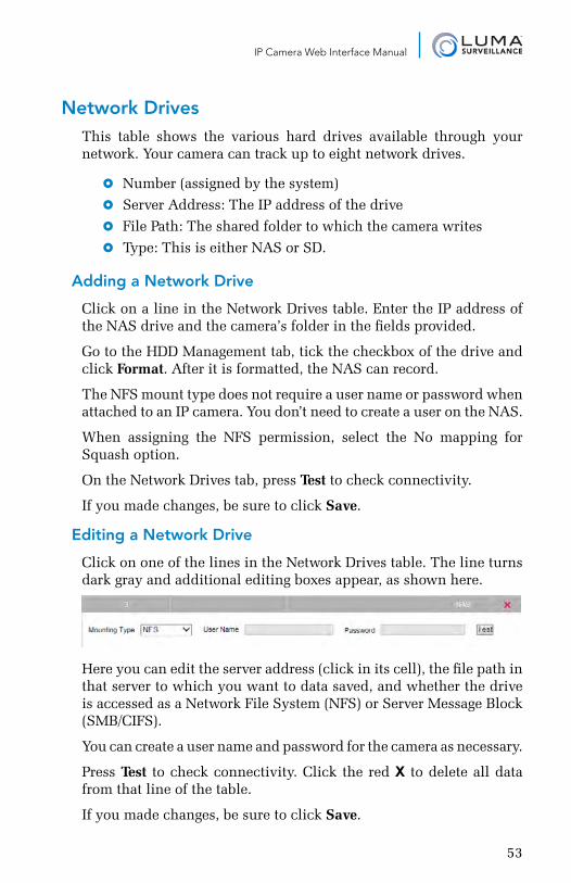
IP Camera Web Interface Manual
Network DrivesThis table shows the various hard drives available through your network. Your camera can track up to eight network drives.
} Number (assigned by the system)
} Server Address: The IP address of the drive
} File Path: The shared folder to which the camera writes
} Type: This is either NAS or SD.
Adding a Network Drive
Click on a line in the Network Drives table. Enter the IP address of the NAS drive and the camera’s folder in the fields provided.
Go to the HDD Management tab, tick the checkbox of the drive and click Format. After it is formatted, the NAS can record.
The NFS mount type does not require a user name or password when attached to an IP camera. You don’t need to create a user on the NAS.
When assigning the NFS permission, select the No mapping for Squash option.
On the Network Drives tab, press Test to check connectivity.
If you made changes, be sure to click Save.
Editing a Network Drive
Click on one of the lines in the Network Drives table. The line turns dark gray and additional editing boxes appear, as shown here.
Here you can edit the server address (click in its cell), the file path in that server to which you want to data saved, and whether the drive is accessed as a Network File System (NFS) or Server Message Block (SMB/CIFS).
You can create a user name and password for the camera as necessary.
Press Test to check connectivity. Click the red X to delete all data from that line of the table.
If you made changes, be sure to click Save.
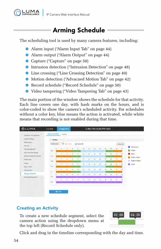
54
IP Camera Web Interface Manual
Arming ScheduleThe scheduling tool is used by many camera features, including:
} Alarm input (“Alarm Input Tab” on page 44)
} Alarm output (“Alarm Output” on page 44)
} Capture (“Capture” on page 50)
} Intrusion detection (“Intrusion Detection” on page 48)
} Line crossing (“Line Crossing Detection” on page 49)
} Motion detection (“Advacned Motion Tab” on page 42)
} Record schedule (“Record Schedule” on page 50)
} Video tampering (“Video Tampering Tab” on page 43)
The main portion of the window shows the schedule for that activity. Each line covers one day, with hash marks on the hours, and is color-coded to show the camera’s scheduled activity. For schedules without a color key, blue means the action is activated, while white means that recording is not enabled during that time.
Creating an Activity
To create a new schedule segment, select the camera action using the dropdown menu at the top left (Record Schedule only).
Click and drag in the timeline corresponding with the day and time.
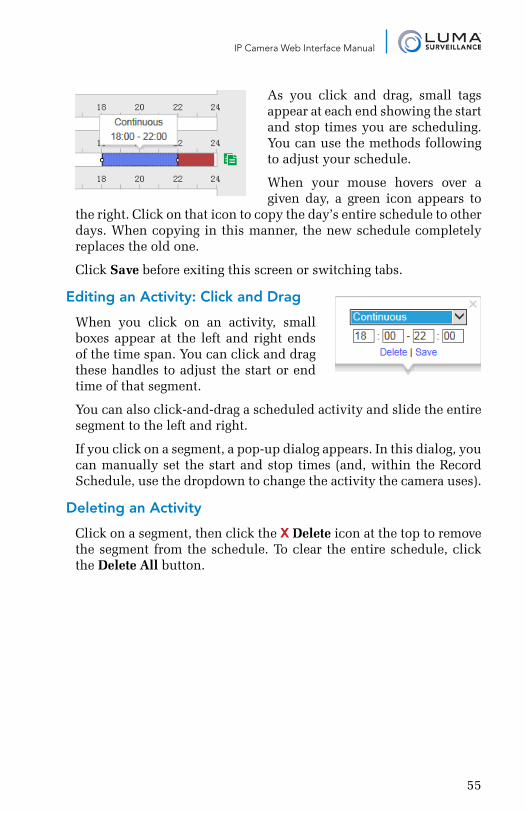
55
IP Camera Web Interface Manual
As you click and drag, small tags appear at each end showing the start and stop times you are scheduling. You can use the methods following to adjust your schedule.
When your mouse hovers over a given day, a green icon appears to
the right. Click on that icon to copy the day’s entire schedule to other days. When copying in this manner, the new schedule completely replaces the old one.
Click Save before exiting this screen or switching tabs.
Editing an Activity: Click and Drag
When you click on an activity, small boxes appear at the left and right ends of the time span. You can click and drag these handles to adjust the start or end time of that segment.
You can also click-and-drag a scheduled activity and slide the entire segment to the left and right.
If you click on a segment, a pop-up dialog appears. In this dialog, you can manually set the start and stop times (and, within the Record Schedule, use the dropdown to change the activity the camera uses).
Deleting an Activity
Click on a segment, then click the X Delete icon at the top to remove the segment from the schedule. To clear the entire schedule, click the Delete All button.
56
IP Camera Web Interface Manual
Linkage MethodLinkages have your surveillance system take action when an event occurs. Examples include locking a door when a motion is detected, activating a light when a door is opened, or alerting key personnel when a camera loses contact. Linkage is used by:
} Alarm input (“Alarm Input Tab” on page 44)
} Intrusion detection (“Intrusion Detection” on page 48)
} Line crossing (“Line Crossing Detection” on page 49)
} Motion detection (“Advacned Motion Tab” on page 42)
} Video tampering (“Video Tampering Tab” on page 43)
Always remember to click Save before leaving this screen.
Setting Up Email Alerts
For complete details (including 2-step verification), see “Setting Up Email Alerts” on page 66.
Normal Linkage This makes the camera take an action when triggered. Click the checkbox beside the action(s) you want taken, or click the checkbox by the column header to enable them all.
Send Email sends an alert if your email protocol has been configured. See “Email Tab” on page 30.
Notify Surveillance Center, when checked, allows your camera to send events to the NVR.
Upload to FTP sends surveillance files to the FTP storage site you’ve designated for your camera (see “FTP Tab” on page 30).
Trigger Alarm Output This has your camera activate its external alarms. The arrow points to which connection gets activated (e.g., A->1 means your camera triggers alarm #1). Click the checkbox beside the alarm to activate it.
Trigger Channel When an external alarm is triggered, you can select which cameras to activate to an event state (and therefore, presumably, recording
57
IP Camera Web Interface Manual
actively and at a higher frame rate). The number beside the letter A refers to the alarm input. Select the checkbox if you want that alarm input to activate the camera. Check the Trigger Channel box to ensure that the camera sends events to the NVR.
Pro Tip: If you want your camera to start recording to an SD card or network drive when an event is triggered, you must select the camera’s own Trigger Channel checkbox.
Untriggered cameras do not store events locally (on their SD or NAS) but still save data on the NVR.
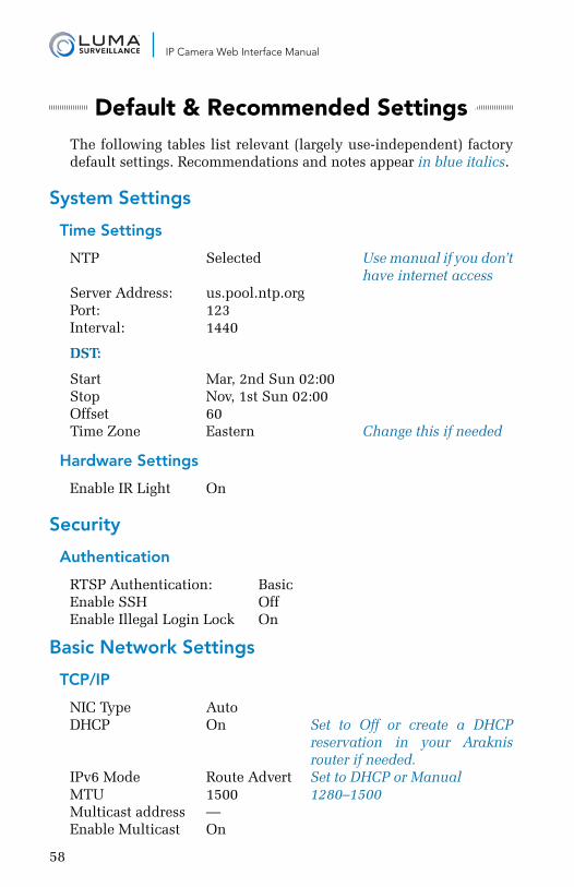
58
IP Camera Web Interface Manual
Default & Recommended SettingsThe following tables list relevant (largely use-independent) factory default settings. Recommendations and notes appear in blue italics.
System Settings
Time Settings
NTP Selected Use manual if you don’t have internet accessServer Address: us.pool.ntp.orgPort: 123Interval: 1440
DST:
Start Mar, 2nd Sun 02:00Stop Nov, 1st Sun 02:00Offset 60Time Zone Eastern Change this if needed
Hardware Settings
Enable IR Light On
Security
Authentication
RTSP Authentication: BasicEnable SSH OffEnable Illegal Login Lock On
Basic Network Settings
TCP/IP
NIC Type AutoDHCP On Set to Off or create a DHCP reservation in your Araknis router if needed.IPv6 Mode Route Advert Set to DHCP or Manual MTU 1500 1280–1500Multicast address —Enable Multicast On
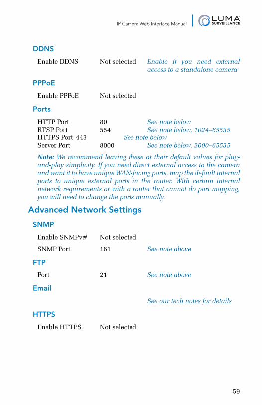
59
IP Camera Web Interface Manual
DDNS
Enable DDNS Not selected Enable if you need external access to a standalone camera
PPPoE
Enable PPPoE Not selected
Ports
HTTP Port 80 See note belowRTSP Port 554 See note below, 1024–65535HTTPS Port 443 See note belowServer Port 8000 See note below, 2000–65535
Note: We recommend leaving these at their default values for plug-and-play simplicity. If you need direct external access to the camera and want it to have unique WAN-facing ports, map the default internal ports to unique external ports in the router. With certain internal network requirements or with a router that cannot do port mapping, you will need to change the ports manually.
Advanced Network Settings
SNMP
Enable SNMPv# Not selected
SNMP Port 161 See note above
FTP
Port 21 See note above
See our tech notes for details
HTTPS
Enable HTTPS Not selected
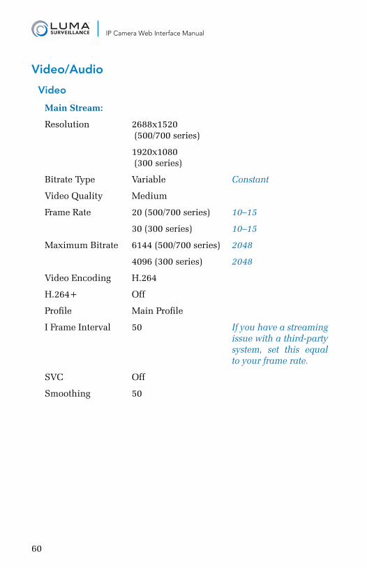
60
IP Camera Web Interface Manual
Video/Audio
Video
Main Stream:
Resolution 2688x1520 (500/700 series)
1920x1080 (300 series)
Bitrate Type Variable Constant
Video Quality Medium
Frame Rate 20 (500/700 series) 10–15
30 (300 series) 10–15
Maximum Bitrate 6144 (500/700 series) 2048
4096 (300 series) 2048
Video Encoding H.264
H.264+ Off
Profile Main Profile
I Frame Interval 50 If you have a streaming issue with a third-party system, set this equal to your frame rate.
SVC Off
Smoothing 50
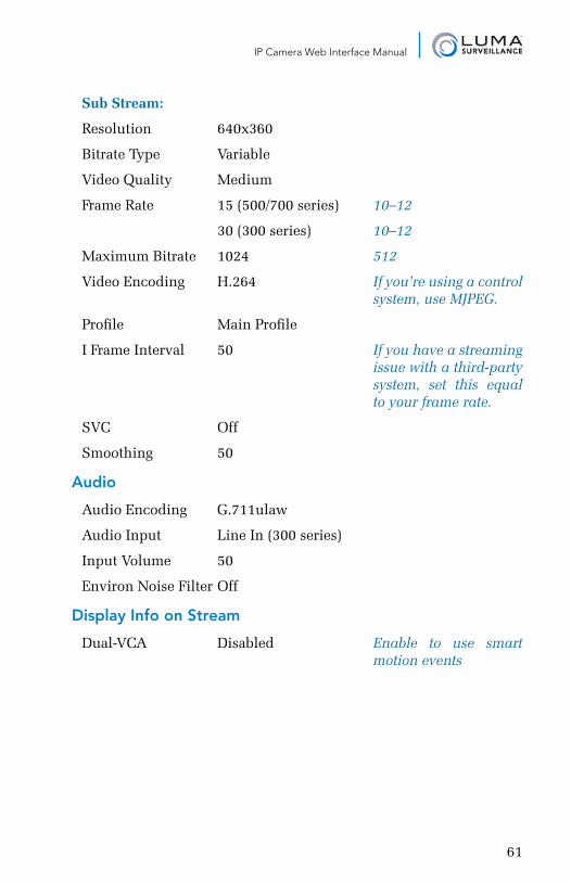
61
IP Camera Web Interface Manual
Sub Stream:
Resolution 640x360
Bitrate Type Variable
Video Quality Medium
Frame Rate 15 (500/700 series) 10–12
30 (300 series) 10–12
Maximum Bitrate 1024 512
Video Encoding H.264 If you’re using a control system, use MJPEG.
Profile Main Profile
I Frame Interval 50 If you have a streaming issue with a third-party system, set this equal to your frame rate.
SVC Off
Smoothing 50
Audio
Audio Encoding G.711ulaw
Audio Input Line In (300 series)
Input Volume 50
Environ Noise Filter Off
Display Info on Stream
Dual-VCA Disabled Enable to use smart motion events
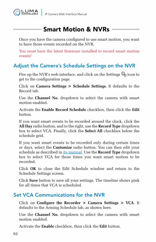
62
IP Camera Web Interface Manual
Smart Motion & NVRsOnce you have the camera configured to use smart motion, you want to have those events recorded on the NVR.
You must have the latest firmware installed to record smart motion events!
Adjust the Camera’s Schedule Settings on the NVR
Fire up the NVR’s web interface, and click on the Settings icon to get to the configuration page.
Click on Camera Settings > Schedule Settings. It defaults to the Record tab.
Use the Channel No. dropdown to select the camera with smart motion enabled.
Activate the Enable Record Schedule checkbox, then click the Edit button.
If you want smart events to be recorded around the clock, click the All Day radio button, and to the right, use the Record Type dropdown box to select VCA. Finally, click the Select All checkbox below the schedule grid.
If you want smart events to be recorded only during certain times or days, select the Customize radio button. You can then edit your schedule as described in its manual. Use the Record Type dropdown box to select VCA for those times you want smart motion to be recorded.
Click OK to close the Edit Schedule window and return to the Schedule Settings screen.
Click Save button to save all your settings. The timeline shows pink for all times that VCA is scheduled.
Set VCA Communications for the NVR Click on Configure the Recorder > Camera Settings > VCA. It defaults to the Arming Schedule tab, as shown here.
Use the Channel No. dropdown to select the camera with smart motion enabled.
Activate the Enable checkbox, then click the Edit button.
63
IP Camera Web Interface Manual
Select the days and time periods for your NVR to accept smart motion events. For details on how to use the schedule tool, see its manual.
Click OK to close the Edit Schedule Time window and return to the VCA screen.
Click the Save button to save all your settings. The timeline shows blue for all times that the NVR will accept smart motion events.
Finding Smart Motion EventsAfter these configurations are made, all Smart/VCA events should be present in playback mode. Smart events show as green in the timeline (whether or not continuous recording was running behind the event).
64
IP Camera Web Interface Manual
Troubleshooting
There’s no timeline!
You are in live mode. The timeline only appears in playback mode.
There are no events in the timeline!
When using the and buttons to search the timeline, only events from the last 48 hours or so are visible. Instead, click your desired date on the calendar, then click the Search button.
Where is the camera’s reset button?
The bullet cameras (500/700 series) have an opening on the bottom. The reset button is inside. For the 300 series bullet, the reset button is on the back of the camera.
For the 500 series turret camera, the reset button is on the pigtail wire.
For all the dome cameras, the reset button is on the camera’s board so the dome cover must be removed first to access the reset button.
Where is the camera’s SD card slot?
Only the following models can use an SD card:
} LUM-300-DOM
} LUM-500-DOM
} LUM-500-BUL
} all LUM-700 series IP cameras
For the dome cameras, the SD card slot is on the camera’s board; you must remove the dome cover to access the SD card slot.
For the bullet cameras, the SD card slot is inside the maintenance plug on the camera’s underside.
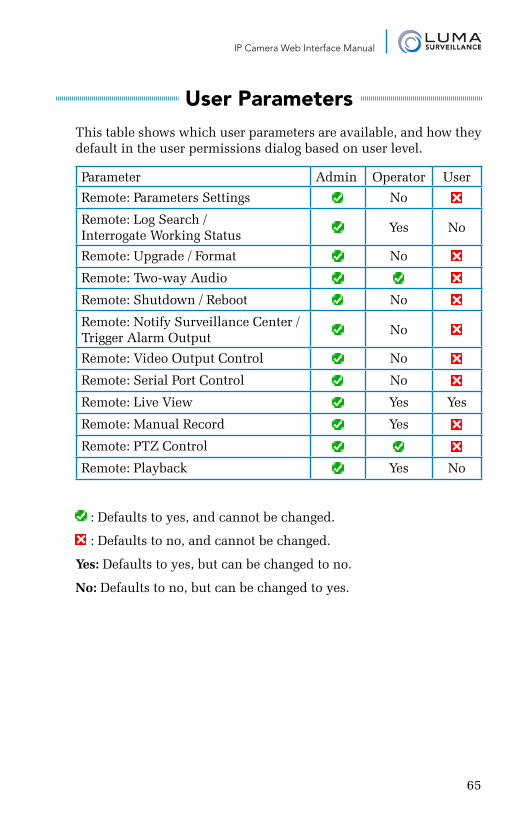
65
IP Camera Web Interface Manual
User ParametersThis table shows which user parameters are available, and how they default in the user permissions dialog based on user level.
Parameter Admin Operator User
Remote: Parameters Settings No
Remote: Log Search / Interrogate Working Status
Yes No
Remote: Upgrade / Format No
Remote: Two-way Audio
Remote: Shutdown / Reboot No
Remote: Notify Surveillance Center / Trigger Alarm Output
No
Remote: Video Output Control No
Remote: Serial Port Control No
Remote: Live View Yes Yes
Remote: Manual Record Yes
Remote: PTZ Control
Remote: Playback Yes No
: Defaults to yes, and cannot be changed.
: Defaults to no, and cannot be changed.
Yes: Defaults to yes, but can be changed to no.
No: Defaults to no, but can be changed to yes.
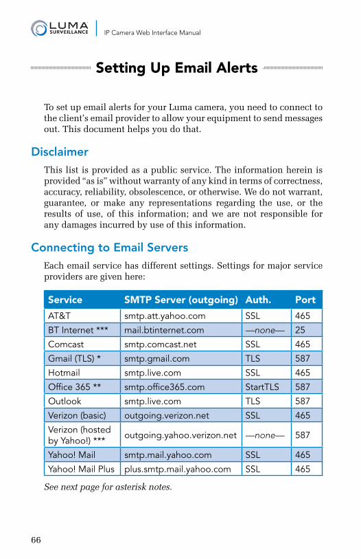
66
IP Camera Web Interface Manual
Setting Up Email Alerts
To set up email alerts for your Luma camera, you need to connect to the client’s email provider to allow your equipment to send messages out. This document helps you do that.
DisclaimerThis list is provided as a public service. The information herein is provided “as is” without warranty of any kind in terms of correctness, accuracy, reliability, obsolescence, or otherwise. We do not warrant, guarantee, or make any representations regarding the use, or the results of use, of this information; and we are not responsible for any damages incurred by use of this information.
Connecting to Email ServersEach email service has different settings. Settings for major service providers are given here:
Service SMTP Server (outgoing) Auth. Port
AT&T smtp.att.yahoo.com SSL 465
BT Internet *** mail.btinternet.com —none— 25
Comcast smtp.comcast.net SSL 465
Gmail (TLS) * smtp.gmail.com TLS 587
Hotmail smtp.live.com SSL 465
Office 365 ** smtp.office365.com StartTLS 587
Outlook smtp.live.com TLS 587
Verizon (basic) outgoing.verizon.net SSL 465
Verizon (hosted by Yahoo!) *** outgoing.yahoo.verizon.net —none— 587
Yahoo! Mail smtp.mail.yahoo.com SSL 465
Yahoo! Mail Plus plus.smtp.mail.yahoo.com SSL 465
See next page for asterisk notes.
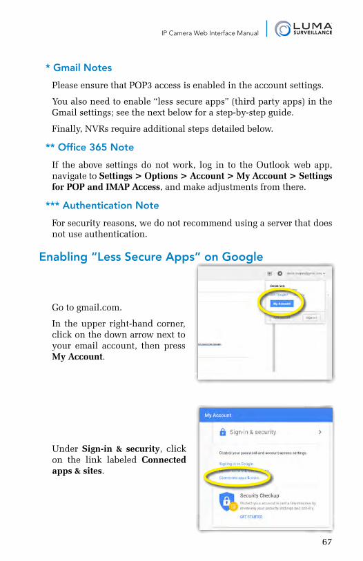
67
IP Camera Web Interface Manual
* Gmail Notes
Please ensure that POP3 access is enabled in the account settings.
You also need to enable “less secure apps” (third party apps) in the Gmail settings; see the next below for a step-by-step guide.
Finally, NVRs require additional steps detailed below.
** Office 365 Note
If the above settings do not work, log in to the Outlook web app, navigate to Settings > Options > Account > My Account > Settings for POP and IMAP Access, and make adjustments from there.
*** Authentication Note
For security reasons, we do not recommend using a server that does not use authentication.
Enabling “Less Secure Apps” on Google
Go to gmail.com.
In the upper right-hand corner, click on the down arrow next to your email account, then press My Account.
Under Sign-in & security, click on the link labeled Connected apps & sites.
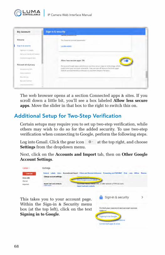
68
IP Camera Web Interface Manual
The web browser opens at a section Connected apps & sites. If you scroll down a little bit, you’ll see a box labeled Allow less secure apps. Move the slider in that box to the right to switch this on.
Additional Setup for Two-Step VerificationCertain setups may require you to set up two-step verification, while others may wish to do so for the added security. To use two-step verification when connecting to Google, perform the following steps.
Log into Gmail. Click the gear icon at the top right, and choose Settings from the dropdown menu.
Next, click on the Accounts and Import tab, then on Other Google Account Settings.
This takes you to your account page. Within the Sign-in & Security menu box (at the top left), click on the text Signing in to Google.
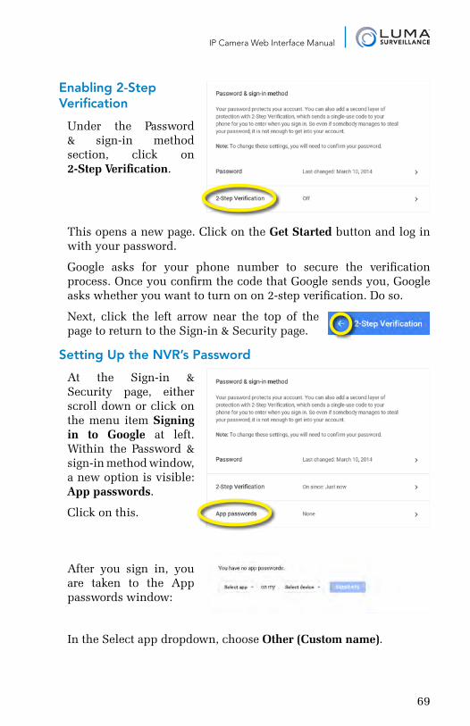
69
IP Camera Web Interface Manual
Enabling 2-Step Verification
Under the Password & sign-in method section, click on 2-Step Verification.
This opens a new page. Click on the Get Started button and log in with your password.
Google asks for your phone number to secure the verification process. Once you confirm the code that Google sends you, Google asks whether you want to turn on on 2-step verification. Do so.
Next, click the left arrow near the top of the page to return to the Sign-in & Security page.
Setting Up the NVR’s Password
At the Sign-in & Security page, either scroll down or click on the menu item Signing in to Google at left. Within the Password & sign-in method window, a new option is visible: App passwords.
Click on this.
After you sign in, you are taken to the App passwords window:
In the Select app dropdown, choose Other (Custom name).
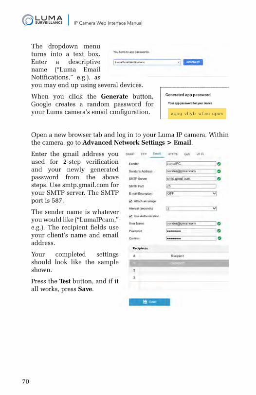
70
IP Camera Web Interface Manual
The dropdown menu turns into a text box. Enter a descriptive name (“Luma Email Notifications,” e.g.), as you may end up using several devices.
When you click the Generate button, Google creates a random password for your Luma camera’s email configuration.
Open a new browser tab and log in to your Luma IP camera. Within the camera, go to Advanced Network Settings > Email.
Enter the gmail address you used for 2-step verification and your newly generated password from the above steps. Use smtp.gmail.com for your SMTP server. The SMTP port is 587.
The sender name is whatever you would like (“LumaIPcam,” e.g.). The recipient fields use your client’s name and email address.
Your completed settings should look like the sample shown.
Press the Test button, and if it all works, press Save.
71
IP Camera Web Interface Manual
Support
Need Help? Contact Tech Support!If you need further clarification, please email [email protected]. For more information, instructional videos, support documentation, or ideas, visit our website and view your item’s product page.
3-Year Limited WarrantyThis Luma Surveillance™ product has a 3-Year Limited Warranty. This warranty includes parts and labor repairs on all components found to be defective in material or workmanship under normal conditions of use. This warranty shall not apply to products that have been abused, modified or disassembled. Products to be repaired under this warranty must be returned to a designated service center with an assigned return authorization (RA) number. Contact technical support for an RA number.
Copyright ©2015–2017 by SnapAV. All rights reserved. SnapAV, Luma Surveillance, and all related marks and images are trademarks or registered trademarks of SnapAV.
Version 170829-0812