Embed Size (px)
DESCRIPTION
was mq v5
Citation preview
ibm.com/redbooks
WebSphere Application Server V5 and WebSphere MQ Family IntegrationQ Family Integration
Jill LennonAshok Ambati
Bill MooreJohn W. MountFred Plassman
Mark SmithPeter von Hirschfeld
Asynchronous integration scenarios with WebSphere products
Discussing security and transactionality
Deployable sample application
Front cover

WebSphere Application Server V5 and WebSphere MQ Family Integration
October 2003
International Technical Support Organization
SG24-6878-00

© Copyright International Business Machines Corporation 2003. All rights reserved.Note to U.S. Government Users Restricted Rights -- Use, duplication or disclosure restricted by GSA ADPSchedule Contract with IBM Corp.
First Edition (October 2003)
This edition applies to WebSphere Application Server Version V5 on Windows 2000 Server, AIX 5.1 ML 2 platforms; MQSeries Version 5.2.1 on Windows 2000 Server; WebSphere MQ Version 5.3.0.1 on Windows 2000 Server and AIX 5.1 ML 2 platforms; WebSphere MQ Integrator Broker Version 2.1 on Windows 2000 Server; WebSphere MQ Event Broker Version 2.1 with CSD3 on Windows 2000 Server; WebSphere Studio Application Developer Version 5 on Windows 2000 Professional.
Note: Before using this information and the product it supports, read the information in “Notices” on page xi.
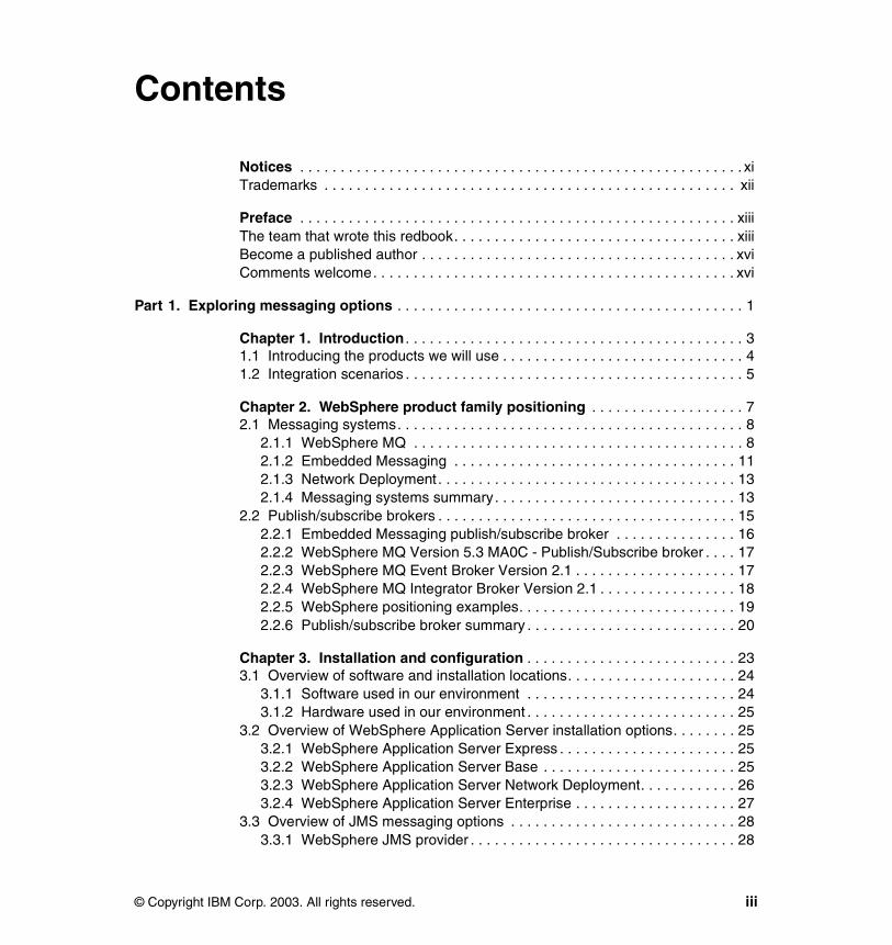
Contents
Notices . . . . . . . . . . . . . . . . . . . . . . . . . . . . . . . . . . . . . . . . . . . . . . . . . . . . . . . xiTrademarks . . . . . . . . . . . . . . . . . . . . . . . . . . . . . . . . . . . . . . . . . . . . . . . . . . . xii
Preface . . . . . . . . . . . . . . . . . . . . . . . . . . . . . . . . . . . . . . . . . . . . . . . . . . . . . . xiiiThe team that wrote this redbook. . . . . . . . . . . . . . . . . . . . . . . . . . . . . . . . . . . xiiiBecome a published author . . . . . . . . . . . . . . . . . . . . . . . . . . . . . . . . . . . . . . . xviComments welcome. . . . . . . . . . . . . . . . . . . . . . . . . . . . . . . . . . . . . . . . . . . . . xvi
Part 1. Exploring messaging options . . . . . . . . . . . . . . . . . . . . . . . . . . . . . . . . . . . . . . . . . . . 1
Chapter 1. Introduction . . . . . . . . . . . . . . . . . . . . . . . . . . . . . . . . . . . . . . . . . . 31.1 Introducing the products we will use . . . . . . . . . . . . . . . . . . . . . . . . . . . . . . 41.2 Integration scenarios . . . . . . . . . . . . . . . . . . . . . . . . . . . . . . . . . . . . . . . . . . 5
Chapter 2. WebSphere product family positioning . . . . . . . . . . . . . . . . . . . 72.1 Messaging systems. . . . . . . . . . . . . . . . . . . . . . . . . . . . . . . . . . . . . . . . . . . 8
2.1.1 WebSphere MQ . . . . . . . . . . . . . . . . . . . . . . . . . . . . . . . . . . . . . . . . . 82.1.2 Embedded Messaging . . . . . . . . . . . . . . . . . . . . . . . . . . . . . . . . . . . 112.1.3 Network Deployment . . . . . . . . . . . . . . . . . . . . . . . . . . . . . . . . . . . . . 132.1.4 Messaging systems summary. . . . . . . . . . . . . . . . . . . . . . . . . . . . . . 13
2.2 Publish/subscribe brokers . . . . . . . . . . . . . . . . . . . . . . . . . . . . . . . . . . . . . 152.2.1 Embedded Messaging publish/subscribe broker . . . . . . . . . . . . . . . 162.2.2 WebSphere MQ Version 5.3 MA0C - Publish/Subscribe broker . . . . 172.2.3 WebSphere MQ Event Broker Version 2.1 . . . . . . . . . . . . . . . . . . . . 172.2.4 WebSphere MQ Integrator Broker Version 2.1 . . . . . . . . . . . . . . . . . 182.2.5 WebSphere positioning examples. . . . . . . . . . . . . . . . . . . . . . . . . . . 192.2.6 Publish/subscribe broker summary . . . . . . . . . . . . . . . . . . . . . . . . . . 20
Chapter 3. Installation and configuration . . . . . . . . . . . . . . . . . . . . . . . . . . 233.1 Overview of software and installation locations. . . . . . . . . . . . . . . . . . . . . 24
3.1.1 Software used in our environment . . . . . . . . . . . . . . . . . . . . . . . . . . 243.1.2 Hardware used in our environment . . . . . . . . . . . . . . . . . . . . . . . . . . 25
3.2 Overview of WebSphere Application Server installation options. . . . . . . . 253.2.1 WebSphere Application Server Express . . . . . . . . . . . . . . . . . . . . . . 253.2.2 WebSphere Application Server Base . . . . . . . . . . . . . . . . . . . . . . . . 253.2.3 WebSphere Application Server Network Deployment. . . . . . . . . . . . 263.2.4 WebSphere Application Server Enterprise . . . . . . . . . . . . . . . . . . . . 27
3.3 Overview of JMS messaging options . . . . . . . . . . . . . . . . . . . . . . . . . . . . 283.3.1 WebSphere JMS provider . . . . . . . . . . . . . . . . . . . . . . . . . . . . . . . . . 28
© Copyright IBM Corp. 2003. All rights reserved. iii
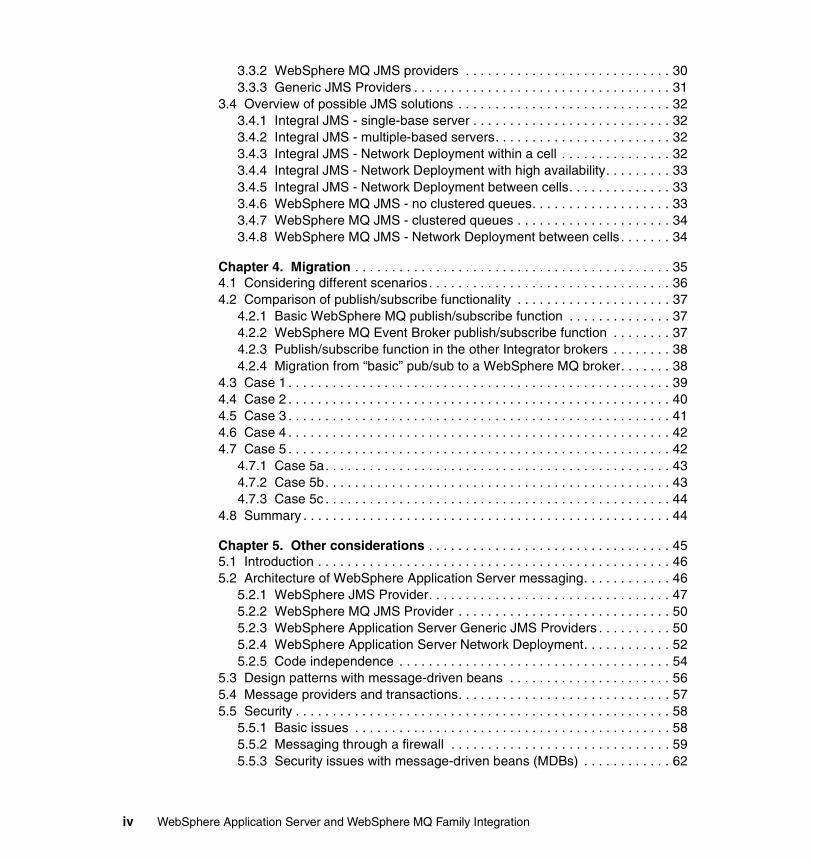
3.3.2 WebSphere MQ JMS providers . . . . . . . . . . . . . . . . . . . . . . . . . . . . 303.3.3 Generic JMS Providers . . . . . . . . . . . . . . . . . . . . . . . . . . . . . . . . . . . 31
3.4 Overview of possible JMS solutions . . . . . . . . . . . . . . . . . . . . . . . . . . . . . 323.4.1 Integral JMS - single-base server . . . . . . . . . . . . . . . . . . . . . . . . . . . 323.4.2 Integral JMS - multiple-based servers. . . . . . . . . . . . . . . . . . . . . . . . 323.4.3 Integral JMS - Network Deployment within a cell . . . . . . . . . . . . . . . 323.4.4 Integral JMS - Network Deployment with high availability. . . . . . . . . 333.4.5 Integral JMS - Network Deployment between cells. . . . . . . . . . . . . . 333.4.6 WebSphere MQ JMS - no clustered queues. . . . . . . . . . . . . . . . . . . 333.4.7 WebSphere MQ JMS - clustered queues . . . . . . . . . . . . . . . . . . . . . 343.4.8 WebSphere MQ JMS - Network Deployment between cells . . . . . . . 34
Chapter 4. Migration . . . . . . . . . . . . . . . . . . . . . . . . . . . . . . . . . . . . . . . . . . . 354.1 Considering different scenarios. . . . . . . . . . . . . . . . . . . . . . . . . . . . . . . . . 364.2 Comparison of publish/subscribe functionality . . . . . . . . . . . . . . . . . . . . . 37
4.2.1 Basic WebSphere MQ publish/subscribe function . . . . . . . . . . . . . . 374.2.2 WebSphere MQ Event Broker publish/subscribe function . . . . . . . . 374.2.3 Publish/subscribe function in the other Integrator brokers . . . . . . . . 384.2.4 Migration from “basic” pub/sub to a WebSphere MQ broker. . . . . . . 38
4.3 Case 1 . . . . . . . . . . . . . . . . . . . . . . . . . . . . . . . . . . . . . . . . . . . . . . . . . . . . 394.4 Case 2 . . . . . . . . . . . . . . . . . . . . . . . . . . . . . . . . . . . . . . . . . . . . . . . . . . . . 404.5 Case 3 . . . . . . . . . . . . . . . . . . . . . . . . . . . . . . . . . . . . . . . . . . . . . . . . . . . . 414.6 Case 4 . . . . . . . . . . . . . . . . . . . . . . . . . . . . . . . . . . . . . . . . . . . . . . . . . . . . 424.7 Case 5 . . . . . . . . . . . . . . . . . . . . . . . . . . . . . . . . . . . . . . . . . . . . . . . . . . . . 42
4.7.1 Case 5a. . . . . . . . . . . . . . . . . . . . . . . . . . . . . . . . . . . . . . . . . . . . . . . 434.7.2 Case 5b. . . . . . . . . . . . . . . . . . . . . . . . . . . . . . . . . . . . . . . . . . . . . . . 434.7.3 Case 5c . . . . . . . . . . . . . . . . . . . . . . . . . . . . . . . . . . . . . . . . . . . . . . . 44
4.8 Summary . . . . . . . . . . . . . . . . . . . . . . . . . . . . . . . . . . . . . . . . . . . . . . . . . . 44
Chapter 5. Other considerations . . . . . . . . . . . . . . . . . . . . . . . . . . . . . . . . . 455.1 Introduction . . . . . . . . . . . . . . . . . . . . . . . . . . . . . . . . . . . . . . . . . . . . . . . . 465.2 Architecture of WebSphere Application Server messaging. . . . . . . . . . . . 46
5.2.1 WebSphere JMS Provider. . . . . . . . . . . . . . . . . . . . . . . . . . . . . . . . . 475.2.2 WebSphere MQ JMS Provider . . . . . . . . . . . . . . . . . . . . . . . . . . . . . 505.2.3 WebSphere Application Server Generic JMS Providers . . . . . . . . . . 505.2.4 WebSphere Application Server Network Deployment. . . . . . . . . . . . 525.2.5 Code independence . . . . . . . . . . . . . . . . . . . . . . . . . . . . . . . . . . . . . 54
5.3 Design patterns with message-driven beans . . . . . . . . . . . . . . . . . . . . . . 565.4 Message providers and transactions. . . . . . . . . . . . . . . . . . . . . . . . . . . . . 575.5 Security . . . . . . . . . . . . . . . . . . . . . . . . . . . . . . . . . . . . . . . . . . . . . . . . . . . 58
5.5.1 Basic issues . . . . . . . . . . . . . . . . . . . . . . . . . . . . . . . . . . . . . . . . . . . 585.5.2 Messaging through a firewall . . . . . . . . . . . . . . . . . . . . . . . . . . . . . . 595.5.3 Security issues with message-driven beans (MDBs) . . . . . . . . . . . . 62
iv WebSphere Application Server and WebSphere MQ Family Integration
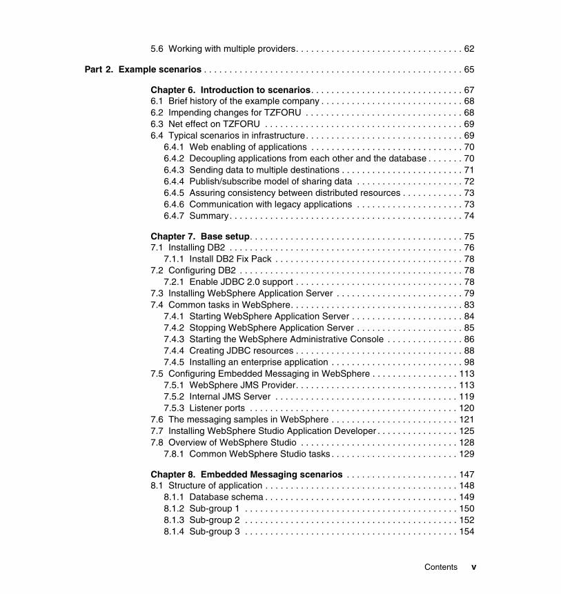
5.6 Working with multiple providers. . . . . . . . . . . . . . . . . . . . . . . . . . . . . . . . . 62
Part 2. Example scenarios . . . . . . . . . . . . . . . . . . . . . . . . . . . . . . . . . . . . . . . . . . . . . . . . . . . 65
Chapter 6. Introduction to scenarios. . . . . . . . . . . . . . . . . . . . . . . . . . . . . . 676.1 Brief history of the example company . . . . . . . . . . . . . . . . . . . . . . . . . . . . 686.2 Impending changes for TZFORU . . . . . . . . . . . . . . . . . . . . . . . . . . . . . . . 686.3 Net effect on TZFORU . . . . . . . . . . . . . . . . . . . . . . . . . . . . . . . . . . . . . . . 696.4 Typical scenarios in infrastructure. . . . . . . . . . . . . . . . . . . . . . . . . . . . . . . 69
6.4.1 Web enabling of applications . . . . . . . . . . . . . . . . . . . . . . . . . . . . . . 706.4.2 Decoupling applications from each other and the database . . . . . . . 706.4.3 Sending data to multiple destinations . . . . . . . . . . . . . . . . . . . . . . . . 716.4.4 Publish/subscribe model of sharing data . . . . . . . . . . . . . . . . . . . . . 726.4.5 Assuring consistency between distributed resources . . . . . . . . . . . . 736.4.6 Communication with legacy applications . . . . . . . . . . . . . . . . . . . . . 736.4.7 Summary. . . . . . . . . . . . . . . . . . . . . . . . . . . . . . . . . . . . . . . . . . . . . . 74
Chapter 7. Base setup. . . . . . . . . . . . . . . . . . . . . . . . . . . . . . . . . . . . . . . . . . 757.1 Installing DB2 . . . . . . . . . . . . . . . . . . . . . . . . . . . . . . . . . . . . . . . . . . . . . . 76
7.1.1 Install DB2 Fix Pack . . . . . . . . . . . . . . . . . . . . . . . . . . . . . . . . . . . . . 787.2 Configuring DB2 . . . . . . . . . . . . . . . . . . . . . . . . . . . . . . . . . . . . . . . . . . . . 78
7.2.1 Enable JDBC 2.0 support . . . . . . . . . . . . . . . . . . . . . . . . . . . . . . . . . 787.3 Installing WebSphere Application Server . . . . . . . . . . . . . . . . . . . . . . . . . 797.4 Common tasks in WebSphere. . . . . . . . . . . . . . . . . . . . . . . . . . . . . . . . . . 83
7.4.1 Starting WebSphere Application Server . . . . . . . . . . . . . . . . . . . . . . 847.4.2 Stopping WebSphere Application Server . . . . . . . . . . . . . . . . . . . . . 857.4.3 Starting the WebSphere Administrative Console . . . . . . . . . . . . . . . 867.4.4 Creating JDBC resources . . . . . . . . . . . . . . . . . . . . . . . . . . . . . . . . . 887.4.5 Installing an enterprise application . . . . . . . . . . . . . . . . . . . . . . . . . . 98
7.5 Configuring Embedded Messaging in WebSphere . . . . . . . . . . . . . . . . . 1137.5.1 WebSphere JMS Provider. . . . . . . . . . . . . . . . . . . . . . . . . . . . . . . . 1137.5.2 Internal JMS Server . . . . . . . . . . . . . . . . . . . . . . . . . . . . . . . . . . . . 1197.5.3 Listener ports . . . . . . . . . . . . . . . . . . . . . . . . . . . . . . . . . . . . . . . . . 120
7.6 The messaging samples in WebSphere . . . . . . . . . . . . . . . . . . . . . . . . . 1217.7 Installing WebSphere Studio Application Developer . . . . . . . . . . . . . . . . 1257.8 Overview of WebSphere Studio . . . . . . . . . . . . . . . . . . . . . . . . . . . . . . . 128
7.8.1 Common WebSphere Studio tasks . . . . . . . . . . . . . . . . . . . . . . . . . 129
Chapter 8. Embedded Messaging scenarios . . . . . . . . . . . . . . . . . . . . . . 1478.1 Structure of application . . . . . . . . . . . . . . . . . . . . . . . . . . . . . . . . . . . . . . 148
8.1.1 Database schema . . . . . . . . . . . . . . . . . . . . . . . . . . . . . . . . . . . . . . 1498.1.2 Sub-group 1 . . . . . . . . . . . . . . . . . . . . . . . . . . . . . . . . . . . . . . . . . . 1508.1.3 Sub-group 2 . . . . . . . . . . . . . . . . . . . . . . . . . . . . . . . . . . . . . . . . . . 1528.1.4 Sub-group 3 . . . . . . . . . . . . . . . . . . . . . . . . . . . . . . . . . . . . . . . . . . 154
Contents v
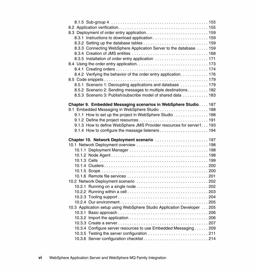
8.1.5 Sub-group 4 . . . . . . . . . . . . . . . . . . . . . . . . . . . . . . . . . . . . . . . . . . 1558.2 Application verification. . . . . . . . . . . . . . . . . . . . . . . . . . . . . . . . . . . . . . . 1558.3 Deployment of order entry application. . . . . . . . . . . . . . . . . . . . . . . . . . . 159
8.3.1 Instructions to download application . . . . . . . . . . . . . . . . . . . . . . . . 1598.3.2 Setting up the database tables . . . . . . . . . . . . . . . . . . . . . . . . . . . . 1598.3.3 Connecting WebSphere Application Server to the database . . . . . 1598.3.4 Creation of JMS entities . . . . . . . . . . . . . . . . . . . . . . . . . . . . . . . . . 1688.3.5 Installation of order entry application . . . . . . . . . . . . . . . . . . . . . . . 171
8.4 Using the order entry application. . . . . . . . . . . . . . . . . . . . . . . . . . . . . . . 1738.4.1 Creating orders . . . . . . . . . . . . . . . . . . . . . . . . . . . . . . . . . . . . . . . . 1748.4.2 Verifying the behavior of the order entry application. . . . . . . . . . . . 176
8.5 Code snippets . . . . . . . . . . . . . . . . . . . . . . . . . . . . . . . . . . . . . . . . . . . . . 1798.5.1 Scenario 1: Decoupling applications and database . . . . . . . . . . . . 1798.5.2 Scenario 2: Sending messages to multiple destinations. . . . . . . . . 1828.5.3 Scenario 3: Publish/subscribe model of shared data . . . . . . . . . . . 183
Chapter 9. Embedded Messaging scenarios in WebSphere Studio . . . . 1879.1 Embedded Messaging in WebSphere Studio . . . . . . . . . . . . . . . . . . . . . 188
9.1.1 How to set up the project in WebSphere Studio . . . . . . . . . . . . . . . 1889.1.2 Define the project resources . . . . . . . . . . . . . . . . . . . . . . . . . . . . . . 1919.1.3 How to define WebSphere JMS Provider resources for server1. . . 1939.1.4 How to configure the message listeners . . . . . . . . . . . . . . . . . . . . . 194
Chapter 10. Network Deployment scenario . . . . . . . . . . . . . . . . . . . . . . . 19710.1 Network Deployment overview . . . . . . . . . . . . . . . . . . . . . . . . . . . . . . . 198
10.1.1 Deployment Manager . . . . . . . . . . . . . . . . . . . . . . . . . . . . . . . . . . 19810.1.2 Node Agent . . . . . . . . . . . . . . . . . . . . . . . . . . . . . . . . . . . . . . . . . . 19810.1.3 Cells . . . . . . . . . . . . . . . . . . . . . . . . . . . . . . . . . . . . . . . . . . . . . . . 19910.1.4 Clusters . . . . . . . . . . . . . . . . . . . . . . . . . . . . . . . . . . . . . . . . . . . . . 20010.1.5 Scope . . . . . . . . . . . . . . . . . . . . . . . . . . . . . . . . . . . . . . . . . . . . . . 20010.1.6 Remote file services . . . . . . . . . . . . . . . . . . . . . . . . . . . . . . . . . . . 201
10.2 Network Deployment scenario . . . . . . . . . . . . . . . . . . . . . . . . . . . . . . . 20210.2.1 Running on a single node . . . . . . . . . . . . . . . . . . . . . . . . . . . . . . . 20210.2.2 Running within a cell . . . . . . . . . . . . . . . . . . . . . . . . . . . . . . . . . . . 20310.2.3 Tooling support . . . . . . . . . . . . . . . . . . . . . . . . . . . . . . . . . . . . . . . 20410.2.4 Our environment . . . . . . . . . . . . . . . . . . . . . . . . . . . . . . . . . . . . . . 205
10.3 Application setup using WebSphere Studio Application Developer . . . 20510.3.1 Basic approach . . . . . . . . . . . . . . . . . . . . . . . . . . . . . . . . . . . . . . . 20610.3.2 Import the application . . . . . . . . . . . . . . . . . . . . . . . . . . . . . . . . . . 20610.3.3 Create a server . . . . . . . . . . . . . . . . . . . . . . . . . . . . . . . . . . . . . . . 20710.3.4 Configure server resources to use Embedded Messaging . . . . . . 20910.3.5 Testing the server configuration . . . . . . . . . . . . . . . . . . . . . . . . . . 21110.3.6 Server configuration checklist . . . . . . . . . . . . . . . . . . . . . . . . . . . . 214
vi WebSphere Application Server and WebSphere MQ Family Integration
10.3.7 Troubleshooting . . . . . . . . . . . . . . . . . . . . . . . . . . . . . . . . . . . . . . 21510.3.8 Moving to WebSphere Application Server . . . . . . . . . . . . . . . . . . 218
10.4 Setting up the environment . . . . . . . . . . . . . . . . . . . . . . . . . . . . . . . . . . 21910.4.1 Installing Network Deployment . . . . . . . . . . . . . . . . . . . . . . . . . . . 21910.4.2 Reviewing the Deployment Manager configuration files . . . . . . . . 22310.4.3 Starting the Deployment Manager . . . . . . . . . . . . . . . . . . . . . . . . 22310.4.4 Add a node to a cell using a command . . . . . . . . . . . . . . . . . . . . . 22510.4.5 Add node using the Administrative Console . . . . . . . . . . . . . . . . . 22810.4.6 Remove node from a cell using a command. . . . . . . . . . . . . . . . . 22810.4.7 Remove a node from a cell using the Administrative Console . . . 22910.4.8 Start the Node Agent using a command . . . . . . . . . . . . . . . . . . . . 23010.4.9 Stop the Node Agent using a command . . . . . . . . . . . . . . . . . . . . 23010.4.10 Start the Deployment Manager using a command . . . . . . . . . . . 23110.4.11 Stop the Deployment Manager using a command . . . . . . . . . . . 23210.4.12 Other Network Deployment commands . . . . . . . . . . . . . . . . . . . 23210.4.13 Exploring the changes. . . . . . . . . . . . . . . . . . . . . . . . . . . . . . . . . 23310.4.14 Creating a new application server. . . . . . . . . . . . . . . . . . . . . . . . 23910.4.15 JMS Server . . . . . . . . . . . . . . . . . . . . . . . . . . . . . . . . . . . . . . . . . 241
10.5 Application setup . . . . . . . . . . . . . . . . . . . . . . . . . . . . . . . . . . . . . . . . . . 24110.5.1 Installing the enterprise archive file. . . . . . . . . . . . . . . . . . . . . . . . 24110.5.2 JMS administration . . . . . . . . . . . . . . . . . . . . . . . . . . . . . . . . . . . . 24310.5.3 Configuring the WebSphere JMS Provider . . . . . . . . . . . . . . . . . . 24410.5.4 Updating the configuration repository . . . . . . . . . . . . . . . . . . . . . . 24810.5.5 Running the EmployeeDetails application. . . . . . . . . . . . . . . . . . . 24910.5.6 Troubleshooting . . . . . . . . . . . . . . . . . . . . . . . . . . . . . . . . . . . . . . 250
10.6 Working with clusters . . . . . . . . . . . . . . . . . . . . . . . . . . . . . . . . . . . . . . 25410.6.1 Cluster management. . . . . . . . . . . . . . . . . . . . . . . . . . . . . . . . . . . 25510.6.2 Creating clusters . . . . . . . . . . . . . . . . . . . . . . . . . . . . . . . . . . . . . . 25610.6.3 Adding a new cluster member. . . . . . . . . . . . . . . . . . . . . . . . . . . . 25610.6.4 Creating cluster members . . . . . . . . . . . . . . . . . . . . . . . . . . . . . . . 25710.6.5 Modification of clusters . . . . . . . . . . . . . . . . . . . . . . . . . . . . . . . . . 25710.6.6 Deploying and managing applications in a cluster . . . . . . . . . . . . 25710.6.7 Starting clusters . . . . . . . . . . . . . . . . . . . . . . . . . . . . . . . . . . . . . . 25810.6.8 Stopping clusters. . . . . . . . . . . . . . . . . . . . . . . . . . . . . . . . . . . . . . 25810.6.9 Remove cluster . . . . . . . . . . . . . . . . . . . . . . . . . . . . . . . . . . . . . . . 259
10.7 Terms . . . . . . . . . . . . . . . . . . . . . . . . . . . . . . . . . . . . . . . . . . . . . . . . . . 259
Chapter 11. XA coordination with WebSphere Application Server . . . . 26111.1 Introduction to transactions . . . . . . . . . . . . . . . . . . . . . . . . . . . . . . . . . . 262
11.1.1 Local transactions . . . . . . . . . . . . . . . . . . . . . . . . . . . . . . . . . . . . . 26211.1.2 Distributed transactions. . . . . . . . . . . . . . . . . . . . . . . . . . . . . . . . . 26211.1.3 Distributed Transaction Processing Model . . . . . . . . . . . . . . . . . . 263
11.2 Support for transactions in JMS . . . . . . . . . . . . . . . . . . . . . . . . . . . . . . 264
Contents vii
11.3 Support for JMS messaging . . . . . . . . . . . . . . . . . . . . . . . . . . . . . . . . . 26511.3.1 Asynchronous message handling in message-driven beans . . . . 265
11.4 Support for transactions . . . . . . . . . . . . . . . . . . . . . . . . . . . . . . . . . . . . 26611.4.1 Container-managed transactions . . . . . . . . . . . . . . . . . . . . . . . . . 26611.4.2 Bean-managed transactions . . . . . . . . . . . . . . . . . . . . . . . . . . . . . 26611.4.3 MDBs with container-managed transactions. . . . . . . . . . . . . . . . . 26711.4.4 MDBs with bean-managed transactions . . . . . . . . . . . . . . . . . . . . 26711.4.5 Creation of a new JMS session in a transaction . . . . . . . . . . . . . . 26811.4.6 Use of XA resources in a transaction . . . . . . . . . . . . . . . . . . . . . . 268
11.5 Architecture of two-phase commit application. . . . . . . . . . . . . . . . . . . . 26811.5.1 Steps performed by the application client . . . . . . . . . . . . . . . . . . . 27111.5.2 Steps performed by the OrderConfirm MDB . . . . . . . . . . . . . . . . . 27111.5.3 Steps performed by the UpdateCustomer MDB . . . . . . . . . . . . . . 271
11.6 Deployment of two-phase commit application. . . . . . . . . . . . . . . . . . . . 27211.6.1 Instructions to download application . . . . . . . . . . . . . . . . . . . . . . . 27211.6.2 Database setup . . . . . . . . . . . . . . . . . . . . . . . . . . . . . . . . . . . . . . . 27211.6.3 Creation of JMS entities . . . . . . . . . . . . . . . . . . . . . . . . . . . . . . . . 27211.6.4 Installation of two-phase commit application. . . . . . . . . . . . . . . . . 274
11.7 Using the two-phase commit application. . . . . . . . . . . . . . . . . . . . . . . . 27411.8 Verification of server-side components . . . . . . . . . . . . . . . . . . . . . . . . . 276
11.8.1 Effect on database . . . . . . . . . . . . . . . . . . . . . . . . . . . . . . . . . . . . 27611.8.2 Contents of WebSphere Application Server logs . . . . . . . . . . . . . 277
11.9 Code in two-phase commit application . . . . . . . . . . . . . . . . . . . . . . . . . 27911.9.1 Application client code . . . . . . . . . . . . . . . . . . . . . . . . . . . . . . . . . 27911.9.2 OrderConfirm MDB - container-managed transactions. . . . . . . . . 28111.9.3 OrderConfirm MDB - bean-managed transactions . . . . . . . . . . . . 284
11.10 Summary . . . . . . . . . . . . . . . . . . . . . . . . . . . . . . . . . . . . . . . . . . . . . . . 287
Chapter 12. Setting up the WebSphere MQ environment . . . . . . . . . . . . 28912.1 Deciding what must be in the environment . . . . . . . . . . . . . . . . . . . . . . 29012.2 Defining the basic MQ environment . . . . . . . . . . . . . . . . . . . . . . . . . . . 290
12.2.1 Installing the WebSphere MQ V5.3.0.1 product . . . . . . . . . . . . . . 29112.2.2 Creating the queue managers. . . . . . . . . . . . . . . . . . . . . . . . . . . . 300
12.3 Defining the WebSphere MQ Integrator Broker on ITSOM1 . . . . . . . . . 30412.4 Defining the WebSphere MQ Event Broker. . . . . . . . . . . . . . . . . . . . . . 309
Chapter 13. WebSphere MQ Provider scenario . . . . . . . . . . . . . . . . . . . . 31513.1 Business case for this scenario. . . . . . . . . . . . . . . . . . . . . . . . . . . . . . . 31613.2 Additional material . . . . . . . . . . . . . . . . . . . . . . . . . . . . . . . . . . . . . . . . . 31713.3 An overview of the systems and processing . . . . . . . . . . . . . . . . . . . . . 31813.4 WebSphere MQ configuration on both systems . . . . . . . . . . . . . . . . . . 319
13.4.1 Setting up the WebSphere MQ infrastructure on ITSOQ1 . . . . . . 31913.4.2 Setting up the WebSphere MQ infrastructure on ITSOM1 . . . . . . 320
viii WebSphere Application Server and WebSphere MQ Family Integration
13.5 WebSphere Application Server configuration on ITSOQ1 . . . . . . . . . . 32213.5.1 Import enterprise archive file . . . . . . . . . . . . . . . . . . . . . . . . . . . . . 32313.5.2 Configuring the WebSphere MQ JMS Provider . . . . . . . . . . . . . . 32313.5.3 Running the employee Web application . . . . . . . . . . . . . . . . . . . . 330
13.6 Configuring WebSphere MQ Event Broker on ITSOQ1 . . . . . . . . . . . . 33413.6.1 Import WebSphere MQ Event Broker message flow . . . . . . . . . . 33513.6.2 Defining topic access rights . . . . . . . . . . . . . . . . . . . . . . . . . . . . . 33613.6.3 Deploy the message flow . . . . . . . . . . . . . . . . . . . . . . . . . . . . . . . 33713.6.4 Monitoring your subscriptions . . . . . . . . . . . . . . . . . . . . . . . . . . . . 338
13.7 WebSphere MQ Integrator Broker configuration on ITSOM1 . . . . . . . . 33913.7.1 Starting WebSphere MQ Integrator Broker resources . . . . . . . . . 33913.7.2 Import WebSphere MQ Integrator Broker message flows . . . . . . 34013.7.3 Deploy the message flows . . . . . . . . . . . . . . . . . . . . . . . . . . . . . . 34113.7.4 A more detailed look at the supplied message flows . . . . . . . . . . 342
Chapter 14. Generic JMS Provider scenario. . . . . . . . . . . . . . . . . . . . . . . 34914.1 Generic JMS Provider and MQSeries V5.2.1 . . . . . . . . . . . . . . . . . . . . 35014.2 Additional material . . . . . . . . . . . . . . . . . . . . . . . . . . . . . . . . . . . . . . . . . 35214.3 MQSeries and WebSphere MQ configuration . . . . . . . . . . . . . . . . . . . . 35214.4 JNDI namspace definition on ITSOQ1 . . . . . . . . . . . . . . . . . . . . . . . . . 353
14.4.1 Environment configuration . . . . . . . . . . . . . . . . . . . . . . . . . . . . . . 35414.4.2 Running JMSAdmin . . . . . . . . . . . . . . . . . . . . . . . . . . . . . . . . . . . 35614.4.3 Creating the namespace . . . . . . . . . . . . . . . . . . . . . . . . . . . . . . . . 356
14.5 WebSphere Application Server configuration on ITSOQ1 . . . . . . . . . . 35814.5.1 Import enterprise archive file . . . . . . . . . . . . . . . . . . . . . . . . . . . . . 35814.5.2 Configuring the Generic JMS Provider . . . . . . . . . . . . . . . . . . . . . 35814.5.3 Running the employee Web application . . . . . . . . . . . . . . . . . . . . 366
14.6 Configuring WebSphere MQ Event Broker on ITSOQ1 . . . . . . . . . . . . 36614.7 WebSphere MQ Integrator Broker configuration on ITSOM1 . . . . . . . . 367
Chapter 15. WebSphere MQ and SSL scenario . . . . . . . . . . . . . . . . . . . . 36915.1 Additional material for the scenario . . . . . . . . . . . . . . . . . . . . . . . . . . . . 37015.2 Using SSL to secure message flow. . . . . . . . . . . . . . . . . . . . . . . . . . . . 370
15.2.1 Generic JMS Provider . . . . . . . . . . . . . . . . . . . . . . . . . . . . . . . . . . 37115.2.2 Overview of SSL . . . . . . . . . . . . . . . . . . . . . . . . . . . . . . . . . . . . . . 37115.2.3 Setting up certificates for SSL. . . . . . . . . . . . . . . . . . . . . . . . . . . . 37215.2.4 Using HTTPS protocol with the browser . . . . . . . . . . . . . . . . . . . . 391
15.3 WebSphere Application Server to WebSphere MQ via SSL . . . . . . . . . 39815.3.1 JMS namespace definition . . . . . . . . . . . . . . . . . . . . . . . . . . . . . . 40015.3.2 Generic JMS Provider configuration . . . . . . . . . . . . . . . . . . . . . . . 40215.3.3 SSL configuration on ITSOS1 . . . . . . . . . . . . . . . . . . . . . . . . . . . . 40315.3.4 SSL configuration on ITSOQ1. . . . . . . . . . . . . . . . . . . . . . . . . . . . 406
Part 3. Appendixes . . . . . . . . . . . . . . . . . . . . . . . . . . . . . . . . . . . . . . . . . . . . . . . . . . . . . . . . 409
Contents ix
Appendix A. WebSphere MQ SupportPacs . . . . . . . . . . . . . . . . . . . . . . . . 411A.1 MA88: MQSeries classes for Java and Java Message Service . . . . . . . 412
A.1.1 MQSeries classes for Java . . . . . . . . . . . . . . . . . . . . . . . . . . . . . . . 412A.1.2 MQSeries classes for Java Message Service (JMS) . . . . . . . . . . . 412
A.2 MA0C: MQSeries - Publish/Subscribe . . . . . . . . . . . . . . . . . . . . . . . . . . 413
Appendix B. WebSphere MQ Provider scenario. . . . . . . . . . . . . . . . . . . . 415B.1 WebSphere MQ setup script . . . . . . . . . . . . . . . . . . . . . . . . . . . . . . . . . . 416
B.1.1 Queue manager ITSOM_QMGR . . . . . . . . . . . . . . . . . . . . . . . . . . 416B.1.2 Queue manager ITSOQ_QMGR . . . . . . . . . . . . . . . . . . . . . . . . . . 420
B.2 ESQL scripts used in the Compute nodes . . . . . . . . . . . . . . . . . . . . . . . 422B.2.1 PAY_SIMPLE_JMSMap message flow: Compute1 node. . . . . . . . 422B.2.2 PAY_SIMPLE_JMSMap message flow: Compute2 node. . . . . . . . 422B.2.3 PAY_SIMPLE_JMSMap message flow: Compute3 node. . . . . . . . 424B.2.4 PAY_Sub2 message flow: Compute1 node . . . . . . . . . . . . . . . . . . 424
B.3 Disabling Embedded Messaging . . . . . . . . . . . . . . . . . . . . . . . . . . . . . . 425
Appendix C. WebSphere MQ and SSL scenario . . . . . . . . . . . . . . . . . . . . 427WebSphere Application Server trace . . . . . . . . . . . . . . . . . . . . . . . . . . . . . . . 428
Appendix D. Generic provider scenario . . . . . . . . . . . . . . . . . . . . . . . . . . 431D.1 JMSAdmin.config . . . . . . . . . . . . . . . . . . . . . . . . . . . . . . . . . . . . . . . . . . 432
Appendix E. Additional material . . . . . . . . . . . . . . . . . . . . . . . . . . . . . . . . 435Locating the Web material . . . . . . . . . . . . . . . . . . . . . . . . . . . . . . . . . . . . . . . 435Using the Web material . . . . . . . . . . . . . . . . . . . . . . . . . . . . . . . . . . . . . . . . . 435
System requirements for downloading the Web material . . . . . . . . . . . . . 436How to use the Web material . . . . . . . . . . . . . . . . . . . . . . . . . . . . . . . . . . 436
Related publications . . . . . . . . . . . . . . . . . . . . . . . . . . . . . . . . . . . . . . . . . . 437IBM Redbooks . . . . . . . . . . . . . . . . . . . . . . . . . . . . . . . . . . . . . . . . . . . . . . . . 437
Other resources . . . . . . . . . . . . . . . . . . . . . . . . . . . . . . . . . . . . . . . . . . . . 437Referenced Web sites . . . . . . . . . . . . . . . . . . . . . . . . . . . . . . . . . . . . . . . . . . 437How to get IBM Redbooks . . . . . . . . . . . . . . . . . . . . . . . . . . . . . . . . . . . . . . . 439
IBM Redbooks collections. . . . . . . . . . . . . . . . . . . . . . . . . . . . . . . . . . . . . 439
Index . . . . . . . . . . . . . . . . . . . . . . . . . . . . . . . . . . . . . . . . . . . . . . . . . . . . . . . 441
x WebSphere Application Server and WebSphere MQ Family Integration
Notices
This information was developed for products and services offered in the U.S.A.
IBM may not offer the products, services, or features discussed in this document in other countries. Consult your local IBM representative for information on the products and services currently available in your area. Any reference to an IBM product, program, or service is not intended to state or imply that only that IBM product, program, or service may be used. Any functionally equivalent product, program, or service that does not infringe any IBM intellectual property right may be used instead. However, it is the user's responsibility to evaluate and verify the operation of any non-IBM product, program, or service.
IBM may have patents or pending patent applications covering subject matter described in this document. The furnishing of this document does not give you any license to these patents. You can send license inquiries, in writing, to: IBM Director of Licensing, IBM Corporation, North Castle Drive Armonk, NY 10504-1785 U.S.A.
The following paragraph does not apply to the United Kingdom or any other country where such provisions are inconsistent with local law: INTERNATIONAL BUSINESS MACHINES CORPORATION PROVIDES THIS PUBLICATION "AS IS" WITHOUT WARRANTY OF ANY KIND, EITHER EXPRESS OR IMPLIED, INCLUDING, BUT NOT LIMITED TO, THE IMPLIED WARRANTIES OF NON-INFRINGEMENT, MERCHANTABILITY OR FITNESS FOR A PARTICULAR PURPOSE. Some states do not allow disclaimer of express or implied warranties in certain transactions, therefore, this statement may not apply to you.
This information could include technical inaccuracies or typographical errors. Changes are periodically made to the information herein; these changes will be incorporated in new editions of the publication. IBM may make improvements and/or changes in the product(s) and/or the program(s) described in this publication at any time without notice.
Any references in this information to non-IBM Web sites are provided for convenience only and do not in any manner serve as an endorsement of those Web sites. The materials at those Web sites are not part of the materials for this IBM product and use of those Web sites is at your own risk.
IBM may use or distribute any of the information you supply in any way it believes appropriate without incurring any obligation to you.
Information concerning non-IBM products was obtained from the suppliers of those products, their published announcements or other publicly available sources. IBM has not tested those products and cannot confirm the accuracy of performance, compatibility or any other claims related to non-IBM products. Questions on the capabilities of non-IBM products should be addressed to the suppliers of those products.
This information contains examples of data and reports used in daily business operations. To illustrate them as completely as possible, the examples include the names of individuals, companies, brands, and products. All of these names are fictitious and any similarity to the names and addresses used by an actual business enterprise is entirely coincidental.
COPYRIGHT LICENSE: This information contains sample application programs in source language, which illustrates programming techniques on various operating platforms. You may copy, modify, and distribute these sample programs in any form without payment to IBM, for the purposes of developing, using, marketing or distributing application programs conforming to the application programming interface for the operating platform for which the sample programs are written. These examples have not been thoroughly tested under all conditions. IBM, therefore, cannot guarantee or imply reliability, serviceability, or function of these programs. You may copy, modify, and distribute these sample programs in any form without payment to IBM for the purposes of developing, using, marketing, or distributing application programs conforming to IBM's application programming interfaces.
© Copyright IBM Corp. 2003. All rights reserved. xi
TrademarksThe following terms are trademarks of the International Business Machines Corporation in the United States, other countries, or both:
developerWorks®ibm.com®z/OS®CICS®DB2 Connect™DB2®
Everyplace®IBM®MQSeries®NetVista™OS/390®Redbooks™
S/390®SupportPac™WebSphere®Redbooks (logo)™
The following terms are trademarks of other companies:
Microsoft, Windows, Windows NT, and the Windows logo are trademarks of Microsoft Corporation in the United States, other countries, or both.
Java and all Java-based trademarks and logos are trademarks or registered trademarks of Sun Microsystems, Inc. in the United States, other countries, or both.
Other company, product, and service names may be trademarks or service marks of others.
xii WebSphere Application Server and WebSphere MQ Family Integration
Preface
This IBM Redbook will help you install, tailor and configure the new Embedded Messaging function in WebSphere® Application Server V5. In addition, the IBM® WebSphere MQ family products are reviewed and positioned with regard to Embedded Messaging.
Part 1, “Exploring messaging options” on page 1 is an introduction to the different WebSphere products, including the WebSphere Application Server and the WebSphere MQ product family. This part also provides detailed instructions for preparing the installation of these products for the scenarios described in the book. You can also read about migration techniques when using earlier versions of MQSeries®.
Part 2, “Example scenarios” on page 65, which is the vast majority of the book, covers the different integration scenarios using the WebSphere product family. These scenarios include WebSphere Application Server with embedded JMS messaging, with external MQ and JMS messaging, and with external generic messaging providers. Integration goes further than just product integration. It includes samples of using WebSphere MQ Integrator for integrating solutions.
“Appendixes” on page 409 provides details on installing and configuring the sample application used for the scenarios in this book.
The team that wrote this redbookThis redbook was produced by a team of specialists from around the world working at the International Technical Support Organization, Hursley Center.
© Copyright IBM Corp. 2003. All rights reserved. xiii
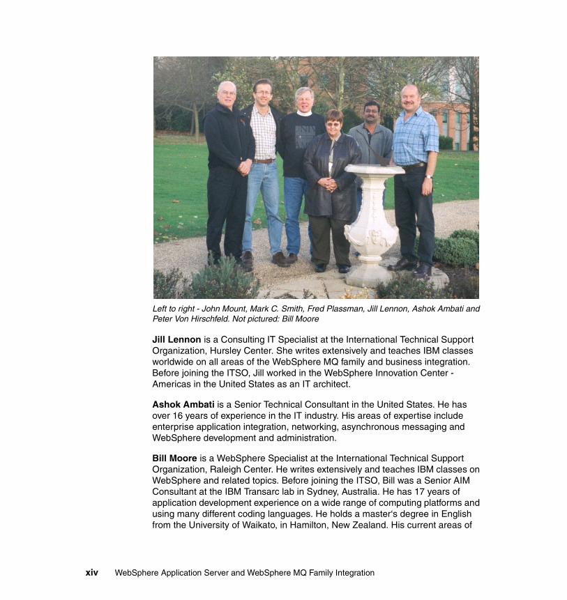
Left to right - John Mount, Mark C. Smith, Fred Plassman, Jill Lennon, Ashok Ambati and Peter Von Hirschfeld. Not pictured: Bill Moore
Jill Lennon is a Consulting IT Specialist at the International Technical Support Organization, Hursley Center. She writes extensively and teaches IBM classes worldwide on all areas of the WebSphere MQ family and business integration. Before joining the ITSO, Jill worked in the WebSphere Innovation Center - Americas in the United States as an IT architect.
Ashok Ambati is a Senior Technical Consultant in the United States. He has over 16 years of experience in the IT industry. His areas of expertise include enterprise application integration, networking, asynchronous messaging and WebSphere development and administration.
Bill Moore is a WebSphere Specialist at the International Technical Support Organization, Raleigh Center. He writes extensively and teaches IBM classes on WebSphere and related topics. Before joining the ITSO, Bill was a Senior AIM Consultant at the IBM Transarc lab in Sydney, Australia. He has 17 years of application development experience on a wide range of computing platforms and using many different coding languages. He holds a master‘s degree in English from the University of Waikato, in Hamilton, New Zealand. His current areas of
xiv WebSphere Application Server and WebSphere MQ Family Integration
expertise include application development tools, object-oriented programming and design, and e-business application development.
John W. Mount is CEO of Venue Software in Sausalito, California. He has seven years of experience in providing asynchronous messaging services to companies.
Fred Plassman is Program Manager for IBM’s MQ Beta programs in the United States. He has over 20 years of experience in the IT industry, with experience on many platforms. His areas of expertise include asynchronous messaging and project management. He has developed and provided technical education for various IBM system management products.
Mark Smith is an Analyst Programmer for Mincom in Australia. He has over 15 years experience in IT and has been working for Mincom for the last five years. His area of expertise is in the development and deployment of business integration systems, and he has worked extensively with WebSphere MQ. Mark also worked on the development of B2B solutions and was involved in the initial pilot of the Quadrem marketplace.
Peter von Hirschfeld is a Senior I/T Specialist with IBM Global Services in Cape Town, South Africa. He has five years of experience in the MQSeries field. He holds a post-graduate degree in psychology from the University of South Africa. His areas of expertise include customer support and consulting for MQSeries and CICS®. He has co-written two other IBM Redbooks™ in the field of e-business solutions for S/390®.
Thanks to the following people for their contributions to this project:
Carla SadtlerInternational Technical Support Organization, Raleigh Center
Niall CliffordWebSphere Messaging Communications Team Leader, IBM Hursley
Jamie RootsWebSphere Messaging Development, IBM Hursley
Kyle SchlosserComponent Broker Development, IBM Rochester
Ian VanstoneWebSphere MQ Development, IBM Hursley
Preface xv
Become a published authorJoin us for a two- to six-week residency program! Help write an IBM Redbook dealing with specific products or solutions, while getting hands-on experience with leading-edge technologies. You'll team with IBM technical professionals, Business Partners and/or customers.
Your efforts will help increase product acceptance and customer satisfaction. As a bonus, you'll develop a network of contacts in IBM development labs, and increase your productivity and marketability.
Find out more about the residency program, browse the residency index, and apply online at:
ibm.com/redbooks/residencies.html
Comments welcomeYour comments are important to us!
We want our Redbooks to be as helpful as possible. Send us your comments about this or other Redbooks in one of the following ways:
� Use the online Contact us review redbook form found at:
ibm.com/redbooks
� Send your comments in an Internet note to:
� Mail your comments to:
IBM Corporation, International Technical Support OrganizationDept. 8IB IBM United Kingdom LtdMP135Hursley, Hampshire S021 2JN
xvi WebSphere Application Server and WebSphere MQ Family Integration
Part 1 Exploring messaging options
Part 1
© Copyright IBM Corp. 2003. All rights reserved. 1

2 WebSphere Application Server and WebSphere MQ Family Integration

Chapter 1. Introduction
This chapter provides an overview of the various products described in this redbook, as well as some terms that will be used throughout. It is not intended to be a thorough discussion of each of these products and terms.
References are provided to other sources of information where the various products and terms can be studied in greater detail.
1
© Copyright IBM Corp. 2003. All rights reserved. 3
1.1 Introducing the products we will useSoftware solutions today typically require the integration of different components within the enterprise. Within e-business architectures, it is becoming more common to find:
� An application server, to provide runtime services to JSPs, servlets and EJBs
� An asynchronous messaging transport, to integrate various applications, from legacy systems to the most current software solutions
� A messaging broker, to provide data transformation, document translation, and routing services
� A process manager, to orchestrate the interaction of a number of applications, towards achieving a business end
Each component of the complete solution (whether it is the application server, message queues, message broker and so on), requires a certain skill set and may be owned by different departments within the enterprise. However, when formulating solutions, the architect must consider how the interactions among the various components influence the application design. The architect must also consider what components of the WebSphere MQ family of products best fit the business process to provide the most complete and robust solution. This redbook aims to give the architect the knowledge to make these decisions by supplying detailed discussions and examples of how these technologies function independently and how they interact.
In this redbook, we examine the interaction between WebSphere Application Server and the members of the WebSphere MQ family and their implications on application design. We will highlight areas for consideration and provide guidance for designing solutions that exploit the messaging technologies in WebSphere Application Server V5 (JMS) and the release of WebSphere MQ Event Broker as well as the availability of WebSphere MQ V5.3 and WebSphere MQ Integrator Broker V2.1.
The architect will be able to build solutions to various business case scenarios, which will utilize different combinations of the above technologies. A step-by-step guide will help the architect get hands-on experience in building integrated solutions that will also display some of the new features in the latest release of WebSphere Application Server and the release of WebSphere MQ Event Broker. The discussion will also include the supported platforms, databases, migration considerations, and product dependencies, as well as any installation and configuration requirements.
The following products are included in this book.
� WebSphere Application Server V5.0
4 WebSphere Application Server and WebSphere MQ Family Integration
� WebSphere MQ V5.3.01� WebSphere MQ Integrator Broker V2.1� WebSphere MQ Integrator V2.1
Although this product will be mentioned here, all subsequent work within this redbook will use WebSphere MQ Integrator Broker V2.1. A brief explanation of the differences between these two products is included in this chapter.
� WebSphere MQ Event Broker V2.1
The first part of this book gives detailed information about the products listed above and provides detailed instructions for installing these particular products.
1.2 Integration scenariosThe second part of the book describes several integration scenarios to the reader. This part starts with Chapter 6, “Introduction to scenarios” on page 67, then is followed by several chapters describing the configuration of the products for each scenario. The other chapters in this part are:
� “Base setup” on page 75
� “Embedded Messaging scenarios” on page 147
� “Embedded Messaging scenarios in WebSphere Studio” on page 187
� “Network Deployment scenario” on page 197
� “XA coordination with WebSphere Application Server” on page 261
� “Setting up the WebSphere MQ environment” on page 289
� “WebSphere MQ Provider scenario” on page 315
� “Generic JMS Provider scenario” on page 349
� “WebSphere MQ and SSL scenario” on page 369
The Appendixes provide further information about the sample application used for this book. The sample application shows the capabilities of each scenario described in Part 2.
To read more about WebSphere messaging scenarios, refer to Selecting the most appropriate JMS provider for your applications, G325-2318-00, by Jamie Roots, June 2003. See the abstract at:
http://www-1.ibm.com/support/docview.wss?uid=pub1e0f13e5870bf07b785256d8a0024ad63
Chapter 1. Introduction 5

6 WebSphere Application Server and WebSphere MQ Family Integration
Chapter 2. WebSphere product family positioning
In this chapter, we describe several WebSphere family products and discuss the environments appropriate for each product. This discussion is not intended to provide complete product descriptions, but should be sufficient to assist you in choosing the appropriate product for your specific use.
In this chapter, we discuss the following products:
� WebSphere MQ Version 5.3.0.1� WebSphere Application Server Version 5 Embedded Messaging� MQSeries Version 5.2.1� WebSphere MQ Integrator Broker Version 2.1� WebSphere MQ Event Broker Version 2.1� Embedded Messaging publish/subscribe broker
As we describe these products, we will relate each product with suggested business uses.
2
© Copyright IBM Corp. 2003. All rights reserved. 7
2.1 Messaging systemsIn this section, we discuss considerations for using messaging systems that are important for positioning among members of the WebSphere MQ product family.
The primary considerations are:
� Java Message Service (JMS) support� Publish/subscribe� Administration tools� Messaging system resources administration� Messaging system transport types� Messaging system remote queuing
We will look at the following messaging systems:
� WebSphere MQ Version 5.3.0.1� WebSphere Application Server Version 5 Embedded Messaging� MQSeries Version 5.2.1
2.1.1 WebSphere MQ In this section, we discuss considerations for using WebSphere MQ Version 5.3.0.1 and prior releases that are important for positioning with other members of the WebSphere MQ product family.
For more information on WebSphere MQ products, use the following URL:
http://www-3.ibm.com/software/integration/wmq/
WebSphere MQ JMS supportJMS Version 1.0.2 support is included in WebSphere MQ Version 5.3.0.1.
The JMS Provider supported with WebSphere MQ Version 5.3.0.1 is referred to as the WebSphere MQ JMS Provider in the WebSphere Application Server Administrative Console (also known as the Admin Console). WebSphere MQ could also be defined as a Generic JMS Provider.
Note: We will use MQSeries Version 5.2.1 as a Generic JMS Provider. See Chapter 14, “Generic JMS Provider scenario” on page 349.
Note: As we proceed, more will be said about this last statement. Be aware that when using SSL within WebSphere MQ V5.3.0.1, you must use the WebSphere Generic JMS Provider, not the WebSphere MQ JMS Provider.
8 WebSphere Application Server and WebSphere MQ Family Integration
MQSeries Version 5.2.1 and prior releases require the MQSeries SupportPac™ MA88 - MQSeries classes for Java and Java Message Service for MQSeries to support JMS.
MQSeries SupportPac MA88 - MQSeries classes for Java and Java Message Service for MQSeries is used in the section about the Generic JMS Provider.
Refer to Chapter 14, “Generic JMS Provider scenario” on page 349 for more information.
For more information on WebSphere MQ SupportPacs, use the following URL:
http://www-3.ibm.com/software/ts/mqseries/txppacs/
For more information about WebSphere MQ SupportPac MA88, refer to Appendix A, “WebSphere MQ SupportPacs” on page 411.
WebSphere MQ publish/subscribePublish/subscribe is provided by:
� WebSphere MQ SupportPac MA0C: MQSeries - Publish/Subscribe� WebSphere MQ Event Broker Version 2.1� WebSphere MQ Integrator Broker Version 2.1
The WebSphere MQ administrator installs and configures these publish/subscribe products.
WebSphere MQ SupportPac MA0C - Publish/Subscribe is not used in this redbook. For more information on WebSphere MQ SupportPacs, use the following URL:
http://www-3.ibm.com/software/ts/mqseries/txppacs/
For more information about WebSphere MQ SupportPacs MA0C, refer to Appendix A, “WebSphere MQ SupportPacs” on page 411.
WebSphere MQ administration toolsWhen configuring a Generic JMS Provider, the MQ JMS administrator populates the Java Naming and Directory Interface (JNDI) namespace with the appropriate JMS Connection Factory (Queue or Topic) and Destination (Queue or Topic) using the WebSphere MQ JMS Administrative Tool (also known as JMSAdmin). The JMSAdmin tool is not used for the other providers.
WebSphere MQ resources administrationThe MQ JMS administrator uses the WebSphere MQ administrative command, crtmqm, to create a WebSphere MQ queue manager.
Chapter 2. WebSphere product family positioning 9
WebSphere MQ resources, such as queues and channels, are defined by the MQ JMS administrator using the WebSphere MQ runmqsc command or WebSphere MQ Explorer snap-in for the Microsoft Management Console (MMC) for Windows.
When embedded messaging is installed, the WebSphere Application Server Administrative Console is used to define the WebSphere MQ queues and the queue manager is automatically created as part of the embedded messaging configuration. There are no channels except a SVRCONN definition used as a template for use when in client mode. There is no need for the WebSphere Application Server administrator to become familiar with or to try to use WebSphere MQ administration tools.
WebSphere MQ clustersWebSphere MQ supports MQ clusters. There are two reasons for using clusters:
1. Reduced system administration.
As soon as you start to establish even a small cluster, you will benefit from simplified system administration. Establishing a network of queue managers in a cluster involves fewer definitions than establishing a network that is to use distributed queuing. With fewer definitions to make, you can set up or change your network more quickly and easily, and reduce the risk of making an error in your definitions.
2. Continuous operations and workload balancing.
Simple clusters give you easier system administration. Moving to more complicated clusters offers improved scalability of the number of instances of a queue you can define, providing continuous operations. Because you can define instances of the same queue on more than one queue manager, the workload can be distributed throughout the queue managers in a cluster.
For more information about WebSphere MQ clusters, refer to WebSphere MQ Queue Managers Clusters, SC34-6061.
WebSphere MQ transport typesWebSphere MQ supports BIND and CLIENT transport types.
� The BIND transport type requires that the JMS application program run on the same computer as the queue manager and uses a native interface to the queue manager. The advantages for using this is that it allows for asynchronous messaging and is faster.
Note: These administration functions are not used when there is only a WebSphere JMS Provider (embedded messaging provider).
10 WebSphere Application Server and WebSphere MQ Family Integration
� The CLIENT transport type allows a JMS application program to run on a computer separate from the computer where the queue manager is running. The queue manager must have a server connection channel defined. This is done in a synchronous fashion and is slower than BIND mode.
The JMS application program uses a TCP/IP network connection to connect to the queue manager.
WebSphere MQ remote queuingWebSphere MQ supports remote queues, enabling queue manager to queue manager communication. For example, an MQ application program running on the same system with a queue manager sends messages to another queue manager on the same or a different system. This configuration requires channels to be defined for both queue managers, plus transmission queues and probably remote queues defined on the sending queue manager. See the WebSphere MQ Intercommunications manual for more information.
WebSphere MQ clusters reduce the system administration required with WebSphere MQ remote queuing.
2.1.2 Embedded MessagingIn this section, we discuss the considerations for using WebSphere Application Server Version 5 Embedded Messaging that are important for positioning with other members of the WebSphere MQ product family.
WebSphere Application Server Version 5 includes technology from WebSphere MQ Version 5.3 in a component called Embedded Messaging. Embedded Messaging provides JMS support and publish/subscribe support. The publish/subscribe support provided with Embedded Messaging uses technology from the WebSphere MQ Event Broker product. The advantages of Embedded Messaging are:
� Preconfigured to simplify administration.
� Queues are created using the WebSphere Application Server tools.
� No need to work directly with the underlying messaging components.
Embedded Messaging JMS supportAll WebSphere MQ messages are internal to the WebSphere Application Server environment; that is, no WebSphere MQ messages flow into or out of the WebSphere Application Server environment.
Chapter 2. WebSphere product family positioning 11
Embedded Messaging does not use all the useful utilities shipped with WebSphere MQ, such as the runmqsc command, WebSphere MQ JMS Administrative Tool (JMSAdmin), WebSphere MQ Explorer, or Services snap-in.
The Embedded Messaging JMS Provider is referred to as the WebSphere JMS Provider in the WebSphere Application Server Administrative Console (also known as the Admin Console).
Embedded Messaging publish/subscribeEmbedded Messaging creates a publish/subscribe broker during the installation process.
For more information about the Embedded Messaging publish/subscribe broker, refer to “Embedded Messaging publish/subscribe broker” on page 16.
Embedded Messaging administration toolsEmbedded Messaging populates the WebSphere Application Server JNDI namespace with the appropriate JMS Connection Factory (Queue or Topic) and Destination (Queue or Topic) using information supplied to the WebSphere Application Server Administrative Console or the WSAdmin tool by the WebSphere Application Server administrator.
For more information on the WSAdmin tool, refer to the InfoCenter.
http://www-3.ibm.com/software/webservers/appserv/infocenter.html
Embedded Messaging resources administrationEmbedded Messaging creates queues using information supplied to the WebSphere Application Server Administrative Console or the WSAdmin tool by the WebSphere Application Server administrator.
For more information on WebSphere MQ resources administration, refer to “WebSphere MQ resources administration” on page 9.
Embedded Messaging clustersEmbedded Messaging does not support MQ clusters.
Embedded Messaging transport typesEmbedded Messaging only supports the BIND transport type.
Embedded Messaging remote queuingEmbedded Messaging does not support remote queuing.
12 WebSphere Application Server and WebSphere MQ Family Integration
2.1.3 Network DeploymentWebSphere Application Server Version 5.0 Network Deployment gives us the ability to route requests to multiple server processes, on multiple machines, as with WebSphere Application Server Version 4 Advanced Edition.
Embedded Messaging provides a specific messaging topology. When WebSphere Application Server Version 5 is installed, you have the option of installing the Embedded Messaging Client, or the Embedded Messaging Server and Client (or no messaging components). If the Embedded Messaging Server is installed onto a node, then that node will host a single JMS Server. For two WebSphere Applications to be able to communicate using JMS, they must be running in the same “cell”, which is the name given to a cluster of Application Server instances that are administered together. In order to exchange JMS messages, the two applications must both connect to the same JMS Server instance. In other words, they must both choose the same node whose JMS Server they are going to use.
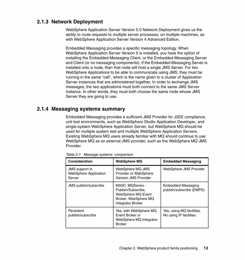
2.1.4 Messaging systems summaryEmbedded Messaging provides a sufficient JMS Provider for J2EE compliance, unit test environments, such as WebSphere Studio Application Developer, and single-system WebSphere Application Server, but WebSphere MQ should be used for multiple system test and multiple WebSphere Application Servers. Existing WebSphere MQ users already familiar with MQ should continue to use WebSphere MQ as an external JMS provider, such as the WebSphere MQ JMS Provider.
Table 2-1 Message systems comparison
Consideration WebSphere MQ Embedded Messaging
JMS support in WebSphere Application Server
WebSphere MQ JMS Provider or WebSphere Generic JMS Provider
WebSphere JMS Provider
JMS publish/subscribe MA0C: MQSeries - Publish/Subscribe, WebSphere MQ Event Broker, WebSphere MQ Integrator Broker
Embedded Messaging publish/subscribe (EMPS)
Persistent publish/subscribe
Yes, with WebSphere MQ Event Broker or WebSphere MQ Integrator Broker
Yes, using MQ facilities.No using IP facilities.
Chapter 2. WebSphere product family positioning 13
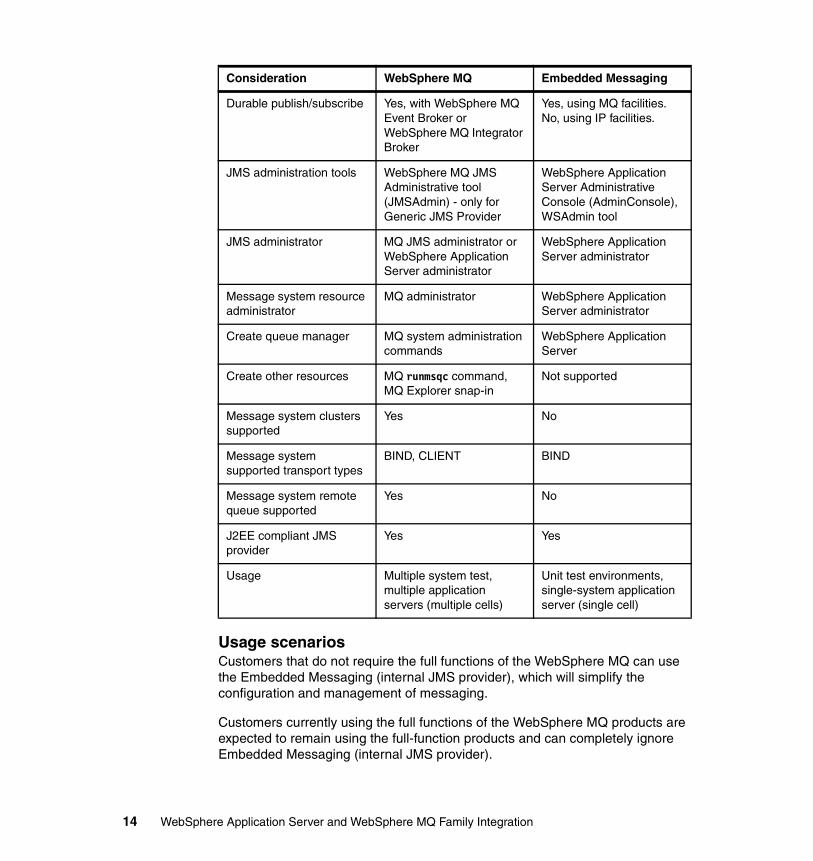
Usage scenariosCustomers that do not require the full functions of the WebSphere MQ can use the Embedded Messaging (internal JMS provider), which will simplify the configuration and management of messaging.
Customers currently using the full functions of the WebSphere MQ products are expected to remain using the full-function products and can completely ignore Embedded Messaging (internal JMS provider).
Durable publish/subscribe Yes, with WebSphere MQ Event Broker or WebSphere MQ Integrator Broker
Yes, using MQ facilities.No, using IP facilities.
JMS administration tools WebSphere MQ JMS Administrative tool (JMSAdmin) - only for Generic JMS Provider
WebSphere Application Server Administrative Console (AdminConsole), WSAdmin tool
JMS administrator MQ JMS administrator or WebSphere Application Server administrator
WebSphere Application Server administrator
Message system resource administrator
MQ administrator WebSphere Application Server administrator
Create queue manager MQ system administration commands
WebSphere Application Server
Create other resources MQ runmsqc command, MQ Explorer snap-in
Not supported
Message system clusters supported
Yes No
Message system supported transport types
BIND, CLIENT BIND
Message system remote queue supported
Yes No
J2EE compliant JMS provider
Yes Yes
Usage Multiple system test, multiple application servers (multiple cells)
Unit test environments, single-system application server (single cell)
Consideration WebSphere MQ Embedded Messaging
14 WebSphere Application Server and WebSphere MQ Family Integration
Customers can also start by using Embedded Messaging (internal JMS provider) and upgrade to the full functions of a WebSphere MQ product at a later time. See Chapter 4, “Migration” on page 35.
2.2 Publish/subscribe brokersPublish/subscribe is a mechanism for anonymous publishers (information suppliers) to provide information to many anonymous subscribers (information consumers who have registered interest in the information the supplier may have). This is achieved as follows:
� Publishers can indicate the topic of their message � Subscribers can choose to receive messages on particular topics
As a publisher, we can deliver messages to ensure that the subscriber receives them, or so that messages are seen only while the subscriber is monitoring for them. Message subscribers can ask to see only certain topics. Within those topics, subscribers can ask to select only messages with certain contents. Their subscriptions can be changed at any time.
In the current release of WebSphere software, there are five products available that can supply a broker environment. These are:
� WebSphere Application Server with Embedded Messaging� WebSphere MQ SupportPac MA0C - Publish/Subscribe� WebSphere MQ Event Broker� WebSphere MQ Integrator Broker� WebSphere MQ Integrator
We did not use WebSphere MQ Integrator in this IBM Redbook. For more information on WebSphere MQ Integrator, use the following URL:
http://www-3.ibm.com/software/ts/mqseries/integrator/v21/index.html
Figure 2-1 on page 16 illustrates the positioning when considering migration of these current products from their previous releases.
Chapter 2. WebSphere product family positioning 15
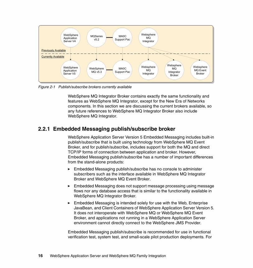
Figure 2-1 Publish/subscribe brokers currently available
WebSphere MQ Integrator Broker contains exactly the same functionality and features as WebSphere MQ Integrator, except for the New Era of Networks components. In this section we are discussing the current brokers available, so any future references to WebSphere MQ Integrator Broker also include WebSphere MQ Integrator.
2.2.1 Embedded Messaging publish/subscribe brokerWebSphere Application Server Version 5 Embedded Messaging includes built-in publish/subscribe that is built using technology from WebSphere MQ Event Broker, and for publish/subscribe, includes support for both the MQ and direct TCP/IP forms of connection between application and broker. However, Embedded Messaging publish/subscribe has a number of important differences from the stand-alone products:
� Embedded Messaging publish/subscribe has no console to administer subscribers such as the interface available in WebSphere MQ Integrator Broker and WebSphere MQ Event Broker.
� Embedded Messaging does not support message processing using message flows nor any database access that is similar to the functionality available in WebSphere MQ Integrator Broker.
� Embedded Messaging is intended solely for use with the Web, Enterprise JavaBean, and Client Containers of WebSphere Application Server Version 5. It does not interoperate with WebSphere MQ or WebSphere MQ Event Broker, and applications not running in a WebSphere Application Server environment cannot directly connect to the WebSphere JMS Provider.
Embedded Messaging publish/subscribe is recommended for use in functional verification test, system test, and small-scale pilot production deployments. For
WebSphereApplicationServer V4
MQSeriesv5.2
MA0CSupport Pac
WebsphereMQ
Integrator
WebSphereMQ v5.3
MA0CSupport Pac
WebsphereMQ Event
Broker
WebsphereMQ
IntegratorBroker
WebsphereMQ
Integrator
Previously Available
Currently Available
WebSphereApplicationServer V5
16 WebSphere Application Server and WebSphere MQ Family Integration
larger production deployments, where throughput or availability considerations suggest the use of a more complex messaging topology, then the use of the WebSphere MQ Event Broker or WebSphere MQ Integrator is recommended.
2.2.2 WebSphere MQ Version 5.3 MA0C - Publish/Subscribe broker
The existing WebSphere MQ SupportPac MA0C - Publish/Subscribe is available for WebSphere MQ Version 5.3.0.1 and earlier releases. With WebSphere MQ using SupportPac MA0C - Publish/Subscribe, we get the persistence of the underlying message queues to enable a more robust and deployable broker environment. WebSphere MQ Publish/Subscribe supplies an acceptable production system, but does not offer the following:
� A graphical user interface. All broker functions use the command line.� No content based filtering.� Flat topic namespace. No hierarchical view.� No ability to receive input using JMS.� No message routing, data transformation or database access.
WebSphere MQ SupportPac MA0C - Publish/Subscribe is the entry point for the publish/subscribe solution with WebSphere MQ. The extra features that are available in WebSphere MQ Event Broker and WebSphere MQ Integrator Broker make these products a more acceptable solution for most of today’s business requirements.
We did not use WebSphere MQ SupportPac MA0C - Publish/Subscribe in this redbook. For more information about WebSphere MQ SupportPac MA0C - Publish/Subscribe, refer to Appendix A, “WebSphere MQ SupportPacs” on page 411.
2.2.3 WebSphere MQ Event Broker Version 2.1WebSphere MQ Event Broker (or just “Event Broker”) offers two transports to give a wide range of quality-of-service and performance options. For fastest performance of nonpersistent messaging, Event Broker has a custom transport, where each application makes a direct TCP/IP connection to the broker, and “nonpersistent” is interpreted as “best effort”, consistent with vendors’ JMS products. For more reliability, message queues with WebSphere MQ message channels are used as the transport. In this case, “nonpersistent” is interpreted
Important: Be aware that this SupportPac has an end of service announced as December 31, 2004. It is recommended that any new publish/subscribe implementation consider using alternative capabilities as we describe in this book.
Chapter 2. WebSphere product family positioning 17
such that every effort is made not to lose messages short of persisting them so as to be recoverable following system failure. The MQ transport must always be used for persistent messaging.
By choosing to use WebSphere Event Broker with WebSphere Application Server we are able to exploit all of the features of those products with our J2EE applications. The cost is that we must separately configure the messaging system itself, using the MQ and Event Broker tools (for example, runmqsc or MQ Explorer), and the connections between the Application Server and Event Broker (for example, using the WebSphere Application Server Administrative Console). Within the Application Server tools, WebSphere MQ and WebSphere MQ Event Broker are referred to collectively as the “WebSphere MQ JMS Provider”.
To use the “MQ Provider”, we install and configure WebSphere MQ and possibly WebSphere Event Broker, and then configure the Application Server to connect to it instead of the Embedded Provider. The MQ products may be installed onto the same machine as the Application Server, or on a different machine. It is necessary to separately install the MQ JMS client into the Application Server environment. The Embedded Messaging Client component of the Application Server install provides all that is needed to make transactional connections both to the Embedded Provider and the MQ Provider.
For more information on WebSphere MQ Event Broker, use the following URL:
http://www-3.ibm.com/software/ts/mqseries/eventbroker/
2.2.4 WebSphere MQ Integrator Broker Version 2.1WebSphere MQ Integrator Broker also works with WebSphere MQ messaging and further extends the publish/subscribe functionality beyond WebSphere MQ Event Broker, to provide a powerful message broker solution driven by business rules. Messages are formed, routed, and transformed according to the rules defined by an easy-to-use graphical user interface.
Diverse applications can exchange information in unlike forms, with brokers handling the processing required for the information to arrive in the right place in the correct format, according to the rules we have defined. The applications have no need to know anything other than their own conventions and requirements.
As in WebSphere MQ Event Broker, applications also have much greater flexibility in selecting which messages they wish to receive, because they can specify a topic filter, or a content-based filter, or both, to control the messages made available to them.
18 WebSphere Application Server and WebSphere MQ Family Integration
The following offerings from IBM are enhanced and extended by WebSphere MQ Integrator Broker Version 2.1:
� MQSeries Integrator Version 2� MQSeries Publish/Subscribe
WebSphere MQ Integrator Broker Version 2.1 extends the capabilities of MQSeries Integrator Versions 2, 2.0.1, and 2.0.2, and MQSeries Publish/Subscribe by supporting:
� Brokers running on the z/OS® operating system
� Enhanced transactional integrity, via XA technology, using DB2®, Oracle, and Sybase on all distributed platforms. IBM Resource Recovery Services (RRS) provide an equivalent level of support with DB2 on z/OS
� Enhanced message definition and processing
For more information on WebSphere MQ Integrator Broker, use the following URL:
http://www-3.ibm.com/software/integration/mqfamily/integrator/broker/
2.2.5 WebSphere positioning examplesHere are some examples of requirements that would require the additional capabilities of WebSphere MQ, WebSphere MQ Event Broker, and/or WebSphere MQ Integrator Broker, which may lead us to prefer the “WebSphere MQ JMS Provider” to the “WebSphere JMS Provider” for some production deployments using WebSphere Application Server:
� The requirement to connect applications running in WebSphere Application Server with applications that use a wide selection of other language environments, runtime environments, and/or hardware platforms, or to connect to a large range of packaged applications that either have native a MQ interface, or for which an adapter is available.
� The requirement to support high message volumes (measured as a function of both message size and number of messages).
With WebSphere MQ, queue manager clustering can be used to distribute messaging workload across multiple queue managers, and to distribute messages across multiple target destinations (for example, across the instances of a cloned application).
� The requirement to decouple sending and receiving application environments, both from one another and from the underlying network that provides connectivity between them.
WebSphere MQ message channels can allow the sending application to continue processing when the receiving application or its hardware is
Chapter 2. WebSphere product family positioning 19
unavailable, or both. Applications may be able to continue operating when the network link is down.
� The requirement to support a large number of independent subscribers.
With WebSphere MQ Event Broker, multiple brokers can be interconnected so as to form a graph structure. This allows publications to be “fanned out” and distributed across an arbitrarily large number of subscribing applications.
� The requirement to reuse existing WebSphere MQ, WebSphere MQ Event Broker or WebSphere MQ Integrator infrastructure.
Many organizations already have an MQ network in place, and may wish to reuse their existing investment. For example, if an MQ queue manager has been configured in an HA environment (such as HACMP or Microsoft Cluster Server), and has spare capacity, then applications running in WebSphere Application Server can also connect to this queue manager and benefit from its high availability. Or, the existing MQ infrastructure may have monitoring and management tools and procedures in place that are just as relevant to J2EE applications as to existing MQ applications.
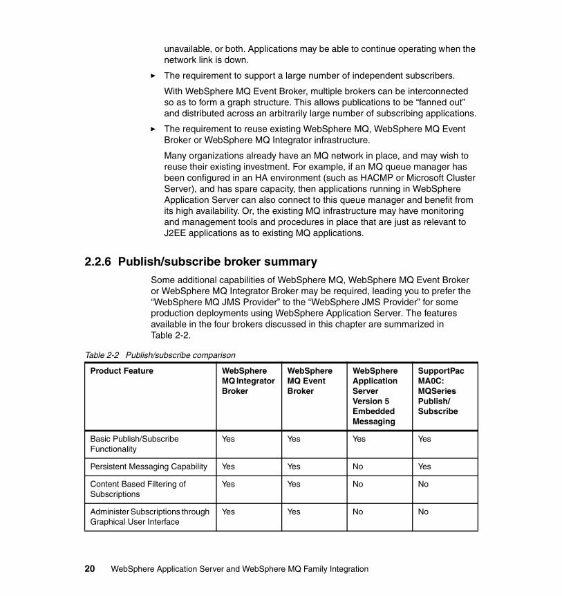
2.2.6 Publish/subscribe broker summarySome additional capabilities of WebSphere MQ, WebSphere MQ Event Broker or WebSphere MQ Integrator Broker may be required, leading you to prefer the “WebSphere MQ JMS Provider” to the “WebSphere JMS Provider” for some production deployments using WebSphere Application Server. The features available in the four brokers discussed in this chapter are summarized in Table 2-2.
Table 2-2 Publish/subscribe comparison
Product Feature WebSphere MQ Integrator Broker
WebSphere MQ Event Broker
WebSphere Application Server Version 5 Embedded Messaging
SupportPac MA0C: MQSeries Publish/ Subscribe
Basic Publish/Subscribe Functionality
Yes Yes Yes Yes
Persistent Messaging Capability Yes Yes No Yes
Content Based Filtering of Subscriptions
Yes Yes No No
Administer Subscriptions through Graphical User Interface
Yes Yes No No
20 WebSphere Application Server and WebSphere MQ Family Integration
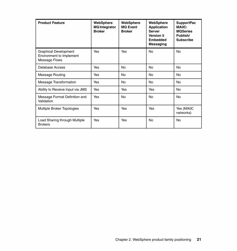
Graphical Development Environment to Implement Message Flows
Yes Yes No No
Database Access Yes No No No
Message Routing Yes No No No
Message Transformation Yes No No No
Ability to Receive Input via JMS Yes Yes Yes No
Message Format Definition and Validation
Yes No No No
Multiple Broker Topologies Yes Yes Yes Yes (MA0C networks)
Load Sharing through Multiple Brokers
Yes Yes No No
Product Feature WebSphere MQ Integrator Broker
WebSphere MQ Event Broker
WebSphere Application Server Version 5 Embedded Messaging
SupportPac MA0C: MQSeries Publish/ Subscribe
Chapter 2. WebSphere product family positioning 21

22 WebSphere Application Server and WebSphere MQ Family Integration
Chapter 3. Installation and configuration
This chapter discusses the installation options available and supported environments for WebSphere Application Server V5, WebSphere MQ V5.3.0.1, WebSphere MQ Event Broker V2.1 and WebSphere MQ Integrator Broker V2.1.
In this chapter, the following topics are described:
� The software and environment that was used to run the scenarios in this redbook
� WebSphere Application Server installation options available
� Overview of the JMS messaging options available in WebSphere Application Server V5
� Operating system, platform, and hardware supported
� Overview of possible JMS solutions
3
© Copyright IBM Corp. 2003. All rights reserved. 23
3.1 Overview of software and installation locationsIn this redbook we have provided a number of scenarios to demonstrate some of the features available in WebSphere Application Server V5 and its ability to integrate with WebSphere MQ V5.3.0.1, MQSeries V5.2.1, WebSphere MQ Event Broker V2.1 and WebSphere MQ Integrator Broker V2.1. The environment that we have used to install, configure, and run these scenarios is listed below.
3.1.1 Software used in our environmentWe used the following software in our environment:
� Microsoft Windows 2000 Professional, Service Pack 2� IBM WebSphere Application Server Version 5, Base� IBM WebSphere Application Server Version 5, Network Deployment� IBM HTTP Server 1.3.27� IBM GSKit 5.0.3.52 (included in IBM HTTP Server package)� IBM DB2 Enterprise Edition Version 7.2, Fix Pack 7� IBM WebSphere MQ Version 5.3.0.1
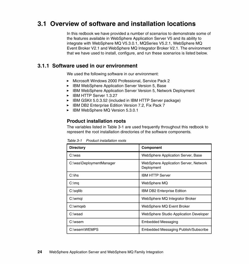
Product installation rootsThe variables listed in Table 3-1 are used frequently throughout this redbook to represent the root installation directories of the software components.
Table 3-1 Product installation roots
Directory Component
C:\was WebSphere Application Server, Base
C:\was\DeploymentManager WebSphere Application Server, Network Deployment
C:\ihs IBM HTTP Server
C:\mq WebSphere MQ
C:\sqllib IBM DB2 Enterprise Edition
C:\wmqi WebSphere MQ Integrator Broker
C:\wmqeb WebSphere MQ Event Broker
C:\wsad WebSphere Studio Application Developer
C:\wsem Embedded Messaging
C:\wsem\WEMPS Embedded Messaging Publish/Subscribe
24 WebSphere Application Server and WebSphere MQ Family Integration
3.1.2 Hardware used in our environmentWe used the following hardware in our environment:
� IBM NetVista™ PC� ~864 MHz processor� 512 MB RAM� 28 GB hard disk� 1 IBM High-Speed 100/16/4 Token-Ring PCI Management Adapter
3.2 Overview of WebSphere Application Server installation options
When installing WebSphere Application Server, there are four installation options available:
� WebSphere Application Server Express� WebSphere Application Server Base� WebSphere Application Server Network Deployment� WebSphere Application Server Enterprise
3.2.1 WebSphere Application Server ExpressIBM WebSphere Application Server Express provides a lightweight version of the Application Server, a CloudScape database for development use, and WebSphere Studio Site Developer. This product targets Web and Web services.
3.2.2 WebSphere Application Server BaseThe WebSphere Application Server Base option provides the following components.
Application serverThis is the primary component in WebSphere. The base application server includes the code for the V5.0 Application Server, which is in full compliance with J2EE 1.3.
IBM HTTP ServerThe Web server used by WebSphere is IBM HTTP Server V1.3.22. The package also includes a preview of IBM HTTP Server 2.0.
Chapter 3. Installation and configuration 25
Application server toolkitThe application server toolkit includes a number of Eclipse-based tooling products. It is a minimal footprint version of development tooling that corresponds to the base tooling provided with WebSphere Studio Application Developer. The toolkit includes a debugger, a tool for application profiling, a log analyzer, and a workbench. It is installed separately from the base.
Application clientThe IBM WebSphere Application Server ships with several different types of application clients. An application client is the interface an application will use to communicate to services provided by applications running on WebSphere Application Server. The application clients available are:
� ActiveX application client� Applet application client� J2EE application client� Pluggable and thin application clients
DataDirect Technologies JDBC driversWebSphere Application Server V5 now supports the following JDBC drivers:
� JDBC drivers provided by a supported database� DataDirect type 3 (SequeLink)� DataDirect type 4 (ConnectJDBC)
3.2.3 WebSphere Application Server Network DeploymentNetwork Deployment includes all of the features of the Base installation as well as the following components.
Deployment ManagerThe Deployment Manager is a process provided by the application server to communicate with independent Node Agents (installed with the base WebSphere Application Server), running in each node in the cell as lightweight (partial J2EE environment) JVM processes. Node Agents coordinate such events as configuration synchronization. The Deployment Manager manages all the nodes in a distributed topology.
Edge ComponentsEdge Components provide a workload management solution that is fully integrated with the WebSphere platform. As part of the workload management solution, a Workload Management Controller can be implemented to provide end-to-end monitoring and weighting of WebSphere Servlet and Enterprise Java Bean containers. This will enable dynamic changes in the workload distribution
26 WebSphere Application Server and WebSphere MQ Family Integration
as the loads on the back-end servers change. This eliminates having to rely on predefined static metrics. The load balancing attributes provided through the Edge Components are exposed through Java Management Extensions (JMX). This allows an administrator to use exposed methods to start and stop the controller, set timeouts, set network communication parameters, and set log levels as well as high-availability parameters. The Edge Components in this package are:
� Workload Management Controller� Switch consultants� Edge-of-network caching technology� Transactional quality of service� Content distribution clients and servers
DB2 Universal Database Enterprise Edition V7.2DB2 had been included in the application server package to provide databases session persistence as well as EJB persistence management. Since DB2 is no longer required to provide the administrative repository, DB2’s main focus is to provide a persistence option out of the box.
IBM Directory V4.1IBM Directory Server provides tight integration with IBM operating systems, middleware, and identity-management and security products, and complies with the LDAP (Lightweight Directory Access Protocol) Versions 2 and 3.
UDDI RegistryUDDI stands for Universal Description, Discovery, and Integration. UDDI is a specification that helps to locate services provided through a service broker. It is an essential element for brokers to use to run a registry of services. It enables the enterprise to run its own Web Services broker within the company or provide brokering services to the outside world.
Web Services GatewayThe gateway allows Web services to be exposed so that they can be invoked outside the firewall in a managed and secure environment.
3.2.4 WebSphere Application Server EnterpriseWebSphere Application Server Enterprise includes all of the features of the Network Deployment installation as well as the following features.
Chapter 3. Installation and configuration 27
Programming ExtensionsWebSphere Extensions are a set of tools that extend the basic capabilities of the WebSphere Programming model and runtime. The extensions provide high-level objects and frameworks for incorporating monitoring, scheduling, messaging, and workflow. These extensions include:
� Dynamic Access Intent� Activity Sessions� Dynamic Query Capabilities� Container Managed Messaging� WebSphere Workflow� Asynchronous Beans� Scheduler� Startup Beans
WebSphere MQ V5.3.0.1WebSphere Application Server Enterprise V5 is shipped with a fully functional version of WebSphere MQ Version 5.3.0.1.
3.3 Overview of JMS messaging optionsWebSphere Application Server provides support for JMS. There are three types of JMS providers available in WebSphere Application Server V5. They are:
� WebSphere JMS providers� WebSphere MQ JMS providers� Generic JMS Providers
3.3.1 WebSphere JMS providerWebSphere includes an embedded JMS provider called the integral JMS provider. This provider is composed of the following IBM products:
� WebSphere MQ
� WebSphere MQ MA88 SupportPac - JMS client classes
� Certain publish/subscribe broker functions (a subset of those used when creating the WebSphere MQ Event Broker), providing the publish/subscribe service
28 WebSphere Application Server and WebSphere MQ Family Integration
Recommended useThe WebSphere JMS provider (also referred to as the integral provider or Embedded Messaging) is recommended for use in the following scenarios:
� When the functionality of full WebSphere MQ is not required. This will simplify configuration and management of the messaging functionality.
� When first introducing messaging into applications. The choice of using the integral JMS provider does not prevent full WebSphere MQ being installed, configured, and used as the JMS provider at a later date as operators become more familiar with messaging. Reinstallation of WebSphere Application Server is not required.
Key featuresThere are several features that are common to both the point-to-point and publish/subscribe functions:
� The integral JMS provider supports the requirements of the J2EE 1.3 specification.
� Security is integrated with the WebSphere Application Server security system, with user and group access being configured using the WebSphere Application Server administration tools.
� The JMS Server hosts the broker and manages the external WebSphere MQ processes.
� All JMS client access, either point-to-point or publish/subscribe, is performed using WebSphere MQ (TCP/IP).
� Tracing is integrated with the WebSphere Application Server tracing infrastructure, with tracing configuration performed via the WebSphere Application Server administration tools.
Note: If WebSphere Application Server V5 is installed on a machine that already has a WebSphere MQ V5.3.0.1 or later installation, the Embedded Messaging that handles point-to-point messaging will not be installed. Instead, the existing WebSphere MQ installation automatically becomes the WebSphere JMS provider. This does not affect the embedded publish/subscribe.
Chapter 3. Installation and configuration 29
3.3.2 WebSphere MQ JMS providersIn order to use the WebSphere MQ JMS provider as an external JMS provider with WebSphere Application Server, the following components must be installed, in addition to the WebSphere Application Server installation:
1. WebSphere MQ V5.3.0.1
2. Broker for publish/subscribe messaging. There are three alternatives that will work with WebSphere Application Server:
– WebSphere MQ MA0C SupportPac - Publish/Subscribe– WebSphere MQ Event Broker– WebSphere MQ Integrator Broker
When the WebSphere MQ JMS provider is implemented, the following points should be considered:
� The broker is not hosted by the application server or the separate JMS Server process. Instead, it is a separate process configured into the WebSphere MQ queue manager.
� The internal JMS Server is not used or required. The management of the queue manager, channels, etc. is performed using the WebSphere MQ native tools. The WebSphere Application Server administration tools do not support configuration or management of these resources.
� The WebSphere Application Server administration tools are used to configure and manage the JMS administered objects (Queue Connection Factories and Queue Destinations) in the local namespace of the application servers that access WebSphere MQ.
� Either client (local or remote) or bind (local only) mode can be used to access WebSphere MQ.
� The full set of WebSphere MQ functionality is available for use, including:
– Store and forward– Queue clustering– Support for different brokers
Key featuresThe WebSphere MQ JMS provider supplies the following features that are not supported by the integral JMS provider of WebSphere Application Server V5:
� Full support for the WebSphere MQ API.
Note: MA0C SupportPac is no longer being updated. We recommend considering one of the other two brokers since they have greater function and will continue to be enhanced.
30 WebSphere Application Server and WebSphere MQ Family Integration
� Support for communication with other WebSphere MQ applications, not just those applications hosted in a WebSphere Application Server environment. This includes communication with JMS and non-JMS applications.
� Support for WebSphere MQ queue manager and channels.
� Support for WebSphere MQ clusters.
� Multi-broker capability.
� Support for integration with existing WebSphere MQ environments.
� Potential for highly available configurations.
3.3.3 Generic JMS ProvidersThe Generic JMS Provider is recommended in the following cases:
� When desiring WebSphere MQ functions not provided in the integral provider but the level of MQ is not V5.3.0.1 or greater.
� When implementing a WebSphere MQ V5.3.0.1 solution that includes SSL support.
� A non-WebSphere MQ messaging system already exists in the environment and into which the WebSphere Application Server installation is required to integrate directly.
� Where a non-WebSphere MQ JMS provider supports functionality that is not available using WebSphere MQ, and which would be useful for the user’s messaging environment.
� Connecting clients in one WebSphere Application Server V5 to JMS Servers in another WebSphere Application Server V5 cell, in order to enable inter-cell messaging.
Key featuresGeneric JMS Providers have the following key features:
� Not limited to WebSphere MQ messaging systems
This may allow integration into non-WebSphere MQ based environments.
� Provides local JNDI aliases for the real JMS connection factory and JMS Destination objects configured into the external namespace, hiding the use of an external provider and its resources from the application.
Chapter 3. Installation and configuration 31
3.4 Overview of possible JMS solutionsWebSphere Application Server support for different JMS providers provides a number of choices with which to implement an asynchronous messaging system. The decision of which scenario is best suited to a particular JMS messaging solution should be made by matching the scenario that best provides the required functions.
3.4.1 Integral JMS - single-base serverThe key features of this configuration are:
� All clients access one JMS Server, hosted inside the application server JVM� No JMS Server failover or high availability� No shared topic space or store and forward� No queue clustering
3.4.2 Integral JMS - multiple-based serversThe key features of this configuration are:
� Applications in each application server can communicate with the JMS Server embedded in the local (same) application server
� No JMS Server failover or high availability
� No shared topic space or store and forward
� No queue clustering
� In order for an application in one application server to interact with the JMS Server on the other application server, a generic JMS connection factory must be configured to point to the remote JMS Server
3.4.3 Integral JMS - Network Deployment within a cellThe key features of this configuration are:
� Applications on any application server in the cell can connect to any JMS Server in the cell, using the JMS administered objects registered in the cell’s federated namespace.
� The JMS Server runs as a separate JVM, enabling it to be started or stopped independent of any application server. A node could be configured to not run a JMS Server.
� No shared topic space or store and forward.
� No queue clustering.
32 WebSphere Application Server and WebSphere MQ Family Integration
� No JMS Server failover or high availability.
3.4.4 Integral JMS - Network Deployment with high availabilityThe key features of this configuration are:
� One of the nodes is dedicated to running the JMS Server (it is not used to run application server processes).
� All other nodes do not run a local JMS Server.
� The applications hosted by the application servers on all other nodes of the cell use the single dedicated JMS Server.
� The machine used for the dedicated JMS is a high availability configuration.
3.4.5 Integral JMS - Network Deployment between cellsThe key features of this configuration are:
� Applications in each cell can communicate with JMS Servers in the same cell by using the WebSphere JMS provider resources in the cell namespace (via JNDI).
� In order for an application in one cell to interact with a JMS Server in another cell, a generic JMS connection factory must be configured in its cell to point at the remote JMS Server.
� No shared topic space or store and forward.
� No queue clustering.
� No JMS Server failover or high availability.
3.4.6 WebSphere MQ JMS - no clustered queuesThe key features of this configuration are:
� If an application has a local queue manager, then store and forward is possible. WebSphere MQ communications using client mode (non-bind) cannot perform store and forward.
� Shared topic space.
� Each queue is independent and distinct.
Chapter 3. Installation and configuration 33
3.4.7 WebSphere MQ JMS - clustered queuesThe key features of this configuration are:
� Clustering is performed at the client end. One or more queue managers are repositories keeping track of the cluster status.
� A client asks a repository for all queue managers hosting a particular clustered queue, and then the client load balances PUT requests between them.
� GET requests are not clustered. A client attaches to a queue on a queue manager and gets messages from it.
3.4.8 WebSphere MQ JMS - Network Deployment between cellsThe key features of this configuration are:
� Shared topic space is possible between cells.
� Store and forward is possible between cells if the node sending the message has a local WebSphere MQ queue manager.
� A client can use queue clustering to spread messages over two cells. This enables one cell to back up the operation of the other.
34 WebSphere Application Server and WebSphere MQ Family Integration

Chapter 4. Migration
This chapter discusses issues that you might need to consider when migrating from your current environment to a new one. There are many different scenarios imaginable, and it would be difficult to try to cover all possible combinations. We will therefore define a few likely options and discuss these in more detail.
We will consider the following scenarios:
� Case 1: Migration from using Embedded Messaging to WebSphere MQ V5.3.0.1 in a WebSphere Application Server V5 environment
� Case 2: Migration from using WebSphere MQ V5.3.0.1 to Embedded Messaging in a WebSphere Application Server V5 environment
� Case 3: WebSphere Application Server V4 with MQSeries V5.2.1 and an infrastructure for both publish/subscribe facilities (such as the MA0C SupportPac) and JMS messaging (such as the MA88 SupportPac), to WebSphere Application Server V5 with WebSphere MQ V5.3.0.1 and WebSphere MQ Event Broker V2.1
� Case 4: WebSphere Application Server V4 with MQSeries V5.2.1 and an infrastructure for both publish/subscribe facilities (such as the MA0C SupportPac) and JMS messaging (such as the MA88 SupportPac), to WebSphere Application Server V5 with MQSeries V5.2.1 and WebSphere MQ Event Broker V2.1
4
© Copyright IBM Corp. 2003. All rights reserved. 35
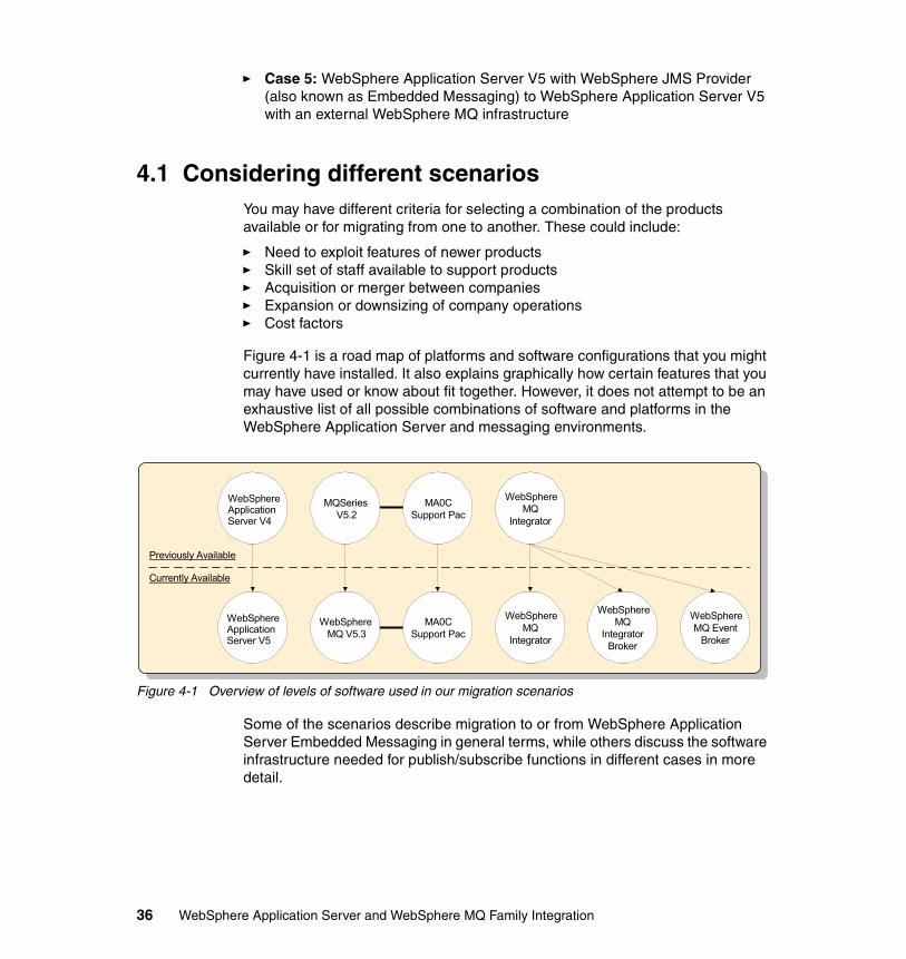
� Case 5: WebSphere Application Server V5 with WebSphere JMS Provider (also known as Embedded Messaging) to WebSphere Application Server V5 with an external WebSphere MQ infrastructure
4.1 Considering different scenariosYou may have different criteria for selecting a combination of the products available or for migrating from one to another. These could include:
� Need to exploit features of newer products� Skill set of staff available to support products� Acquisition or merger between companies� Expansion or downsizing of company operations� Cost factors
Figure 4-1 is a road map of platforms and software configurations that you might currently have installed. It also explains graphically how certain features that you may have used or know about fit together. However, it does not attempt to be an exhaustive list of all possible combinations of software and platforms in the WebSphere Application Server and messaging environments.
Figure 4-1 Overview of levels of software used in our migration scenarios
Some of the scenarios describe migration to or from WebSphere Application Server Embedded Messaging in general terms, while others discuss the software infrastructure needed for publish/subscribe functions in different cases in more detail.
WebSphereApplicationServer V4
MQSeriesV5.2
MA0CSupport Pac
WebSphereMQ
Integrator
WebSphereMQ V5.3
MA0CSupport Pac
WebSphereMQ Event
Broker
WebSphereMQ
IntegratorBroker
WebSphereMQ
Integrator
Previously Available
Currently Available
WebSphereApplicationServer V5
36 WebSphere Application Server and WebSphere MQ Family Integration
4.2 Comparison of publish/subscribe functionality
Before we discuss the different scenarios in more detail, a short description of the concept of publish/subscribe is provided, to allow you to understand the levels of functionality available from the different products in the “broker” family. For more information, consult the relevant manuals for the different publish/subscribe products mentioned below.
4.2.1 Basic WebSphere MQ publish/subscribe functionThis publish/subscribe capability is based on the MA0C SupportPac that can be added to a base WebSphere MQ V5.2 or V5.3 system. It allows publish/subscribe functionality with the following restrictions:
� There is a flat namespace for topics (that is, there is no hierarchy of topics subscribed to).
� No content-based routing. Content-based routing allows you to use a filter statement in the MQRFH2 psc folder to register subscribers based on the content of a message.
� No Access Control Lists (ACLs) for topic-based security. An ACL is a list of users who have permission to publish, to subscribe to, and to request delivery of publications. ACLs are used to implement topic-based security.
� No centralized topology definition.
� Less flexibility and control in using existing applications, because there is no GUI-based control center administration user interface.
4.2.2 WebSphere MQ Event Broker publish/subscribe functionThis publish/subscribe capability expands on the functionality of the basic WebSphere MQ Publish/Subscribe function by offering:
� ACLs on topic-based subscriptions.
� A GUI-based control center administration user interface. This allows easy manageability and control of publish/subscribe applications.
� Support for different transport protocols. WebSphere MQ Event Broker can support:
– IP– SCADA (input and output nodes)
Note: In the following discussion, we use the term “broker” family to refer to WebSphere MQ Integrator Broker and WebSphere MQ Integrator generically.
Chapter 4. Migration 37
– WebSphere MQ (input and output nodes)– WebSphere MQ Everyplace® (input and output nodes)
� Support on a wider range of platforms than MA0C (for example the “basic” publish/subscribe functionality in MA0C is not available under Linux for z/OS, Windows XP and native z/OS).
By using the JMSIPInput node as the input node for a message flow, you can set up an environment ideal for high-speed, nonpersistent publish/subscribe messages. This node “listens” directly on a TCP/IP port for messages, without using the full WebSphere MQ transport protocol. This might be useful, for example, where you are running a stock market publish/subscribe application where the subscribers require high-speed, almost real-time access to changes in stock prices.
You can also use the JMSIPOptimizedFlow node, which has an internalized message input and output. The node is deployed as a message flow itself, and brokers can publish or subscribe directly to the message flow.
There is no Compute node in WebSphere MQ Event Broker. However, you can implement content-based routing using the filters set up by subscribers.
4.2.3 Publish/subscribe function in the other Integrator brokersThe WebSphere MQ Integrator Broker and WebSphere MQ Integrator brokers offer identical publish/subscribe functionality. They also allow you to filter messages based on content using the MQFH2.psc.Filter folder, and to subscribe to topics using the MQFH2.psc.Topic.
4.2.4 Migration from “basic” pub/sub to a WebSphere MQ broker
If you decide that you require the increased functionality offered by one of the WebSphere MQ brokers, you can plan and execute a migration from the MA0C “basic” publish/subscribe environment to one offered by WebSphere MQ Event Broker, WebSphere MQ Integrator Broker, or WebSphere MQ Integrator. You should examine the functions offered by the various broker products discussed above and decide which one fits your publish/subscribe application requirements.
The migmqbrk migration toolIf you are currently using the basic WebSphere MQ Publish/Subscribe broker, you can use the migmqbrk tool to migrate to either a WebSphere MQ Event Broker broker, a WebSphere MQ Integrator Broker broker, or a WebSphere MQ Integrator broker. This tool is discussed in WebSphere MQ Event Broker
38 WebSphere Application Server and WebSphere MQ Family Integration
Administration Guide, WebSphere MQ Integrator Broker Administration Guide, and WebSphere MQ Integrator Administration Guide.
The tool allows you to migrate a publish/subscribe configuration that uses the basic WebSphere MQ Publish/Subscribe broker to a more complex one that takes advantage of the additional publish/subscribe functions available in WebSphere MQ Event Broker, WebSphere MQ Integrator Broker, or WebSphere MQ Integrator. It allows you to migrate in a step-by-step fashion. Applications written using the MA0C SupportPac publish/subscribe functions can run unchanged on WebSphere MQ Event Broker.
4.3 Case 1Case 1 discusses the situation where you migrate from Embedded Messaging to WebSphere MQ. You might find it useful to start using WebSphere Application Server Embedded Messaging for messaging services and resources for WebSphere enterprise applications, and then migrate to using WebSphere MQ. These could be:
� When you are setting up a test environment for experimenting with messaging facilities from WebSphere Application Server.
Embedded Messaging services are automatically installed as part of the WebSphere Application Server Version 5 installation. You can use Embedded Messaging as your JMS provider to start experimenting with messages being sent to or from an application using JMS.
� When you have a requirement to use features of WebSphere MQ that are not available in the Embedded Messaging environment of WebSphere Application Server.
As you develop messaging applications that are more complex, you may find that you require features available only in WebSphere MQ, for example:
– MQ clustering
– Putting a message to a queue that forms part of a message flow in WebSphere MQ Integrator or WebSphere MQ Integrator Broker
– Using the WebSphere MQ Event Broker
You also need to use an external WebSphere MQ in order to use messaging between a J2EE application and a non-J2EE application.
To make use of WebSphere MQ as your JMS provider, you need to install WebSphere MQ. Make sure that during this installation process you selected Java Messaging and Server. You do not need to redefine or delete any existing
Chapter 4. Migration 39
resources that you are currently using for Embedded Messaging when you start using WebSphere MQ as your JMS provider.
You can also use both Embedded Messaging and WebSphere MQ JMS as JMS providers for WebSphere applications. This could be useful in a situation where you run both point-to-point and publish/subscribe applications:
� In your point-to-point applications, you can use suitable resources defined via the embedded JMS provider, in addition to resources known to external WebSphere MQ and recognized by WebSphere Application Server.
� In your publish/subscribe applications you can use the appropriate topic definitions defined via the embedded JMS provider, as well as WebSphere MQ resources that are linked to WebSphere MQ Integrator Broker or WebSphere MQ Event Broker, for example.
WebSphere Application Server uses various resources to access WebSphere MQ objects. You should use the WebSphere Application Server Administrative Console to define any new resources that WebSphere MQ will use for JMS purposes. These resources are used by WebSphere Application Server and are not defined within WebSphere MQ:
� Queue Connection Factory� Topic Connection Factory� Queue Destination� Topic Destination
Refer to the relevant section in the WebSphere Application Server InfoCenter for detailed instructions on how to define these resources.
http://publib.boulder.ibm.com/infocenter/wasinfo/index.jsp
4.4 Case 2Case 2 discusses the situation where you migrate from WebSphere MQ to Embedded Messaging.
You may feel that you would prefer to migrate to using Embedded Messaging for messaging services and resources for WebSphere enterprise applications after using the full WebSphere MQ product. This could be when you are downsizing from an environment using WebSphere MQ facilities to one that uses WebSphere Application Server only.
You should be aware that you will lose a considerable degree of functionality when migrating in this direction. Specifically, you will not be able to use WebSphere MQ clustering, connect to external queue managers, or put message onto a queue that can be further used as input to a node in a
40 WebSphere Application Server and WebSphere MQ Family Integration
WebSphere MQ Integrator Broker or WebSphere MQ Event Broker message flow.
4.5 Case 3Case 3 discusses the situation where you migrate from using WebSphere Application Server V4 with MQSeries V5.2 and a publish/subscribe capability to WebSphere Application Server V5 with MQSeries V5.3.0.1 and MQ Event Broker. This scenario assumes that you currently use WebSphere Application Server V4 together with a publish/subscribe function within MQSeries V5.2 and JMS messaging, and that you want to migrate to WebSphere Application Server V5 using WebSphere MQ Event Broker on WebSphere MQ V5.3.0.1. Your reasons for performing this migration might be:
� You want to move to the latest version of WebSphere Application Server to make use of new features.
� You want to use stream queues in a WebSphere MQ cluster. (The broker used with the MA0C publish/subscribe SupportPac on MQSeries V5.1 or V5.2 cannot handle stream queues that are part of an MQ cluster.)
The migration process for WebSphere Application Server V4 to WebSphere Application Server V5 is documented in the InfoCenter:
http://publib.boulder.ibm.com/infocenter/wasinfo/index.jsp
The important differences in your environment will be:
� The installation of WebSphere MQ Event Broker together with WebSphere MQ V5.3.0.1
� The use of the WebSphere MQ JMS Provider in WebSphere Application Server to handle messaging application flows
You need to decide whether you want to run a single network of brokers, or one where MQ publish/subscribe functions are handled separately and independently from those of the WebSphere MQ Event Broker. It is important to remember that you cannot use one queue manager to share broker functions for MQ publish/subscribe and WebSphere MQ Event Broker.
The decision as to whether to leave your broker networks separate or move towards integrating them should be based on considerations such as whether you want publications from the MQ publish/subscribe to be available to WebSphere MQ Event Broker subscribers. For more information about migration issues and the migration process, refer to WebSphere MQ Event Broker Administration Guide.
Chapter 4. Migration 41
Once you have migrated WebSphere Application Server from V4 to V5, the process you would follow is:
1. Install WebSphere MQ V5.3.0.1.
2. Install WebSphere MQ Event Broker.
3. Set up a separate queue manager to test publish/subscribe functions before deciding on an integration policy.
4. Set up the WebSphere MQ JMS Provider in WebSphere Application Server to communicate with the WebSphere MQ structure that underpins WebSphere MQ Event Broker. For details of how to do this, see Chapter 13, “WebSphere MQ Provider scenario” on page 315.
4.6 Case 4Case 4 discusses the situation where you migrate from using WebSphere Application Server V4 with MQSeries V5.2 and a publish/subscribe capability to WebSphere Application Server V5 with MQSeries V5.2 and MQ Event Broker. This scenario assumes that you currently use WebSphere Application Server V4 together with a publish/subscribe function within MQSeries V5.2, and that you want to migrate to WebSphere Application Server V5 using WebSphere MQ Event Broker, but you want to stay on MQSeries V5.2. Your reasons for performing this migration might be:
� You want to make use of WebSphere MQ Event Broker technology, but you are not ready to move to WebSphere MQ V5.3.0.1.
� You want to move to the latest version of WebSphere Application Server to make use of new features.
The migration process for WebSphere Application Server V4 to WebSphere Application Server V5 is documented in the InfoCenter.
http://publib.boulder.ibm.com/infocenter/wasinfo/index.jsp
The important difference in your environment will be that you are using a Generic JMS Provider in WebSphere Application Server to handle messaging application flows.
4.7 Case 5Case 5 discusses the situation where you migrate from WebSphere Application Server V5 with WebSphere JMS Provider to WebSphere Application Server V5 with an external WebSphere MQ infrastructure (either WebSphere MQ Event Broker, WebSphere MQ Integrator Broker, or WebSphere MQ Integrator). These
42 WebSphere Application Server and WebSphere MQ Family Integration
migration scenarios might be appropriate if you decide that you need to make more extensive use of the facilities available in WebSphere MQ when connected to one of the MQ products allowing advanced publish/subscribe functionality and/or other options such as message transformation, routing or database updating, or access within a message flow.
4.7.1 Case 5aMigrating to WebSphere MQ Event Broker has the following advantages:
� Scalability - allowing you to connect multiple brokers in one or more collectives
� A GUI-based control center for setup and administration of message flows
� Integration and interoperability using the Application Messaging Interface (AMI) and the MQI (MQ Interface) for application development
� Access to a high performance input node in a WebSphere MQ Event Broker message flow
This node, known as the JMSIPInput node, makes use of a TCP/IP port for listening for input messages to process and send to a publication node, rather than using the WebSphere MQ transport infrastructure. It is ideally suited to high volume, high-speed, nonpersistent publish/subscribe applications.
� Access to the JMSIPOptimizedFlow node
This node has an internalized message flow, optimized for JMS publishing and JMS subscribing.
4.7.2 Case 5bMigrating to WebSphere MQ Integrator Broker has the following advantages:
� Scalability - allowing you to connect multiple brokers in one or more collectives
� A GUI-based control center for setup and administration of message flows
� Integration and interoperability using the Application Messaging Interface (AMI) and the MQI (MQ Interface) for application development
� Access to powerful options in complex message flows that allow you to perform one or more of the following functions:
– Message transformation– Message routing– Database access or updates– Filtering
Chapter 4. Migration 43
For publish/subscribe messaging WebSphere applications, you can use resources defined via the Embedded Messaging JMS provider. Alternatively, you can use WebSphere MQ resources defined to WebSphere Application Server that are handled by a publish/subscribe broker in WebSphere MQ.
4.7.3 Case 5cMigrating to WebSphere MQ Integrator has all the advantages of migrating to the other members of the “broker” family already mentioned. In addition, you can support messages defined using the New Era of Networks Formatter with flows in WebSphere MQ Integrator V2.1.
4.8 SummaryIn the preceding sections, we have discussed some of the more common migrations possible. However, there are other combinations that could be considered. You should consult the appropriate WebSphere MQ documentation for a more detailed discussion of the benefits of each particular WebSphere MQ product, and to determine which one provides the functionality required for your business case.
44 WebSphere Application Server and WebSphere MQ Family Integration
Chapter 5. Other considerations
In this chapter, we discuss the followings issues of Embedded Messaging in WebSphere Application Server 5:
� Architecture and how WebSphere Application Server containers support messaging by type of message provider
� How to maintain code independence across Embedded Messaging providers
� Design patterns of interest with message-driven beans
� Web services and Embedded Messaging
� Security policy and design alternatives
� Working with multiple messaging providers
� Using an older version of MQSeries
5
© Copyright IBM Corp. 2003. All rights reserved. 45
5.1 IntroductionThe appearance of JMS as an integral part of WebSphere Application Server will put new tools in the hands of developers. Many will be new to the design patterns and implications of messaged-based applications. They may not have been directly involved in the more operations-related elements of configuring message-based transports. They will have to make new choices regarding security and, in particular, consider how best to enable requesters from outside of the enterprise to gain access to resources inside.
Here, we identify the characteristics of messaging infrastructures needed for J2EE applications using messaging and in particular the Java Message Service.
5.2 Architecture of WebSphere Application Server messaging
The topologies of the three kinds of messaging supported by WebSphere Application Server 5.0 differ in important respects. Understanding these differences can help you to understand the design intentions and purposes of each of them. A detailed discussion of these architectures is beyond the scope of this book but can be found in Chapter 7, “Asynchronous Messaging”, in IBM WebSphere Application Server Version 5.0 Handbook, SG24-6195.
Here, our purpose is to provide simplified designs to help you to understand how the various components of WebSphere Application Server are used. A number of important capabilities, such as communication between queue managers and the availability of security services, depend on the visibility of these between Java Virtual Machines (JVM). In particular, note that:
� For WebSphere JMS Providers, the JMS Server resides inside the JVM. Consequently it cannot be utilized from processes running in other JVMs and for this reason queue managers are not shared. The name server as well as administration tools are built-in as well. In a similar fashion, security is the domain of the embedded security server and it also resides in the JVM. The components of this configuration are summarized in Figure 5-1 on page 47 and Figure 5-2 on page 49.
� WebSphere MQ JMS Providers place the queue manager outside the JVM. Consequently these can be managed externally and can be shared. Naming remains within the JVM. However, security responsibilities are shared between JVM and the container. Because of this, the security server cannot be used for SSL. The components for WebSphere MQ JMS Providers are shown in Figure 5-3 on page 50.
46 WebSphere Application Server and WebSphere MQ Family Integration
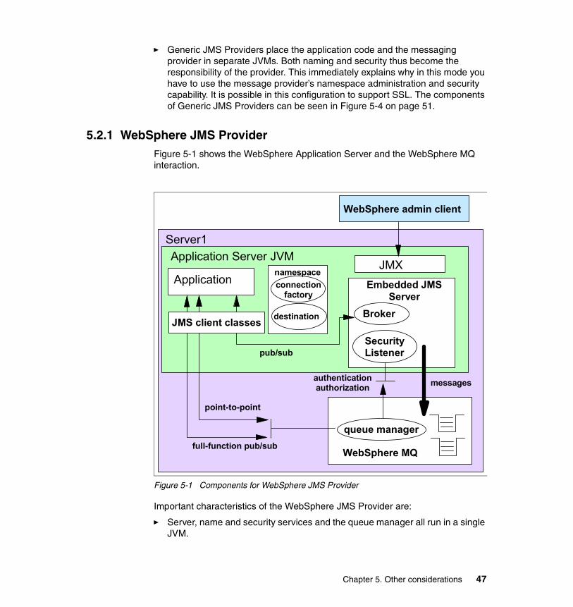
� Generic JMS Providers place the application code and the messaging provider in separate JVMs. Both naming and security thus become the responsibility of the provider. This immediately explains why in this mode you have to use the message provider’s namespace administration and security capability. It is possible in this configuration to support SSL. The components of Generic JMS Providers can be seen in Figure 5-4 on page 51.
5.2.1 WebSphere JMS ProviderFigure 5-1 shows the WebSphere Application Server and the WebSphere MQ interaction.
Figure 5-1 Components for WebSphere JMS Provider
Important characteristics of the WebSphere JMS Provider are:
� Server, name and security services and the queue manager all run in a single JVM.
Application Embedded JMS Server
Broker
Security Listener
Server1Application Server JVM
authentication authorization
point-to-point
JMX
WebSphere MQ
queue manager
messages
full-function pub/sub
connection factory
destination
namespace
pub/sub
JMS client classes
WebSphere admin client
Chapter 5. Other considerations 47
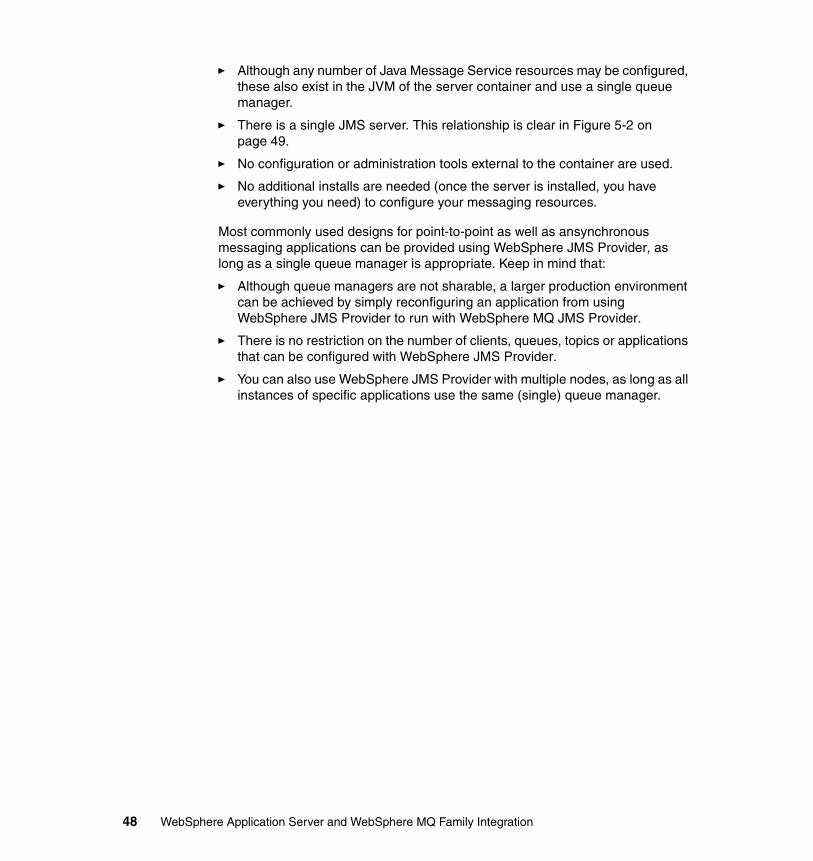
� Although any number of Java Message Service resources may be configured, these also exist in the JVM of the server container and use a single queue manager.
� There is a single JMS server. This relationship is clear in Figure 5-2 on page 49.
� No configuration or administration tools external to the container are used.
� No additional installs are needed (once the server is installed, you have everything you need) to configure your messaging resources.
Most commonly used designs for point-to-point as well as ansynchronous messaging applications can be provided using WebSphere JMS Provider, as long as a single queue manager is appropriate. Keep in mind that:
� Although queue managers are not sharable, a larger production environment can be achieved by simply reconfiguring an application from using WebSphere JMS Provider to run with WebSphere MQ JMS Provider.
� There is no restriction on the number of clients, queues, topics or applications that can be configured with WebSphere JMS Provider.
� You can also use WebSphere JMS Provider with multiple nodes, as long as all instances of specific applications use the same (single) queue manager.
48 WebSphere Application Server and WebSphere MQ Family Integration
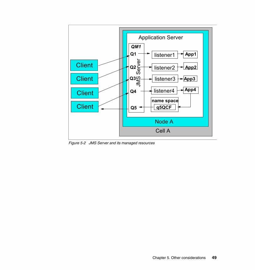
Figure 5-2 JMS Server and its managed resources
Client
Client
Client
Client
Application Server
JMS
Serv
er
App1
App2
Q1
Q2
Q3
Q4
App3
App4
listener1
listener2
listener3
listener4
Q5name space
q5QCF
QM1
Node ACell A
Chapter 5. Other considerations 49
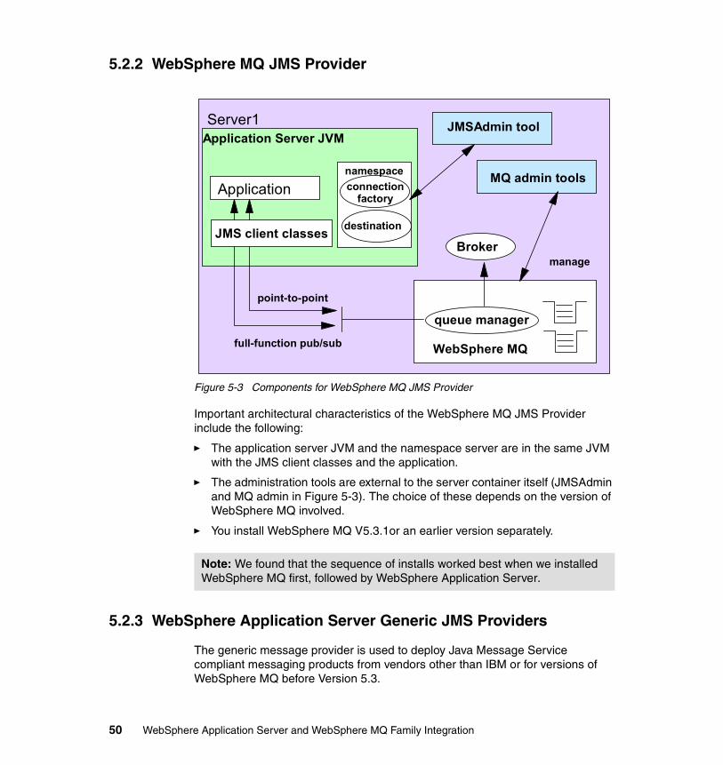
5.2.2 WebSphere MQ JMS Provider
Figure 5-3 Components for WebSphere MQ JMS Provider
Important architectural characteristics of the WebSphere MQ JMS Provider include the following:
� The application server JVM and the namespace server are in the same JVM with the JMS client classes and the application.
� The administration tools are external to the server container itself (JMSAdmin and MQ admin in Figure 5-3). The choice of these depends on the version of WebSphere MQ involved.
� You install WebSphere MQ V5.3.1or an earlier version separately.
5.2.3 WebSphere Application Server Generic JMS Providers
The generic message provider is used to deploy Java Message Service compliant messaging products from vendors other than IBM or for versions of WebSphere MQ before Version 5.3.
Note: We found that the sequence of installs worked best when we installed WebSphere MQ first, followed by WebSphere Application Server.
Application
Server1Application Server JVM
point-to-point
full-function pub/sub
connection factory
destination
namespace
JMS client classes
JMSAdmin tool
Broker
WebSphere MQ
queue manager
manage
MQ admin tools
50 WebSphere Application Server and WebSphere MQ Family Integration
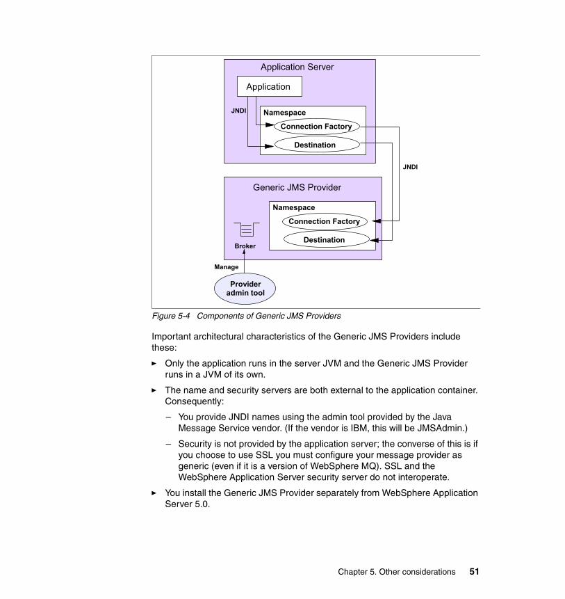
Figure 5-4 Components of Generic JMS Providers
Important architectural characteristics of the Generic JMS Providers include these:
� Only the application runs in the server JVM and the Generic JMS Provider runs in a JVM of its own.
� The name and security servers are both external to the application container. Consequently:
– You provide JNDI names using the admin tool provided by the Java Message Service vendor. (If the vendor is IBM, this will be JMSAdmin.)
– Security is not provided by the application server; the converse of this is if you choose to use SSL you must configure your message provider as generic (even if it is a version of WebSphere MQ). SSL and the WebSphere Application Server security server do not interoperate.
� You install the Generic JMS Provider separately from WebSphere Application Server 5.0.
Application
Namespace
Connection Factory
Destination
Namespace
Connection Factory
Destination
Generic JMS Provider
JNDI
Application Server
Provider admin tool
JNDI
Manage
Broker
Chapter 5. Other considerations 51
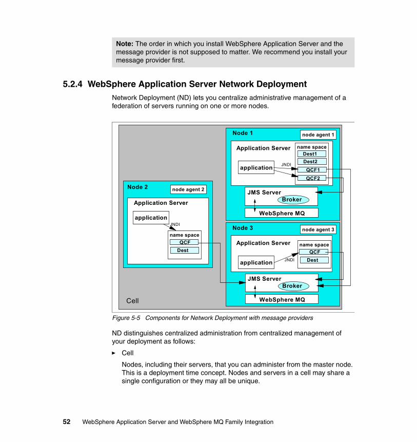
5.2.4 WebSphere Application Server Network DeploymentNetwork Deployment (ND) lets you centralize administrative management of a federation of servers running on one or more nodes.
Figure 5-5 Components for Network Deployment with message providers
ND distinguishes centralized administration from centralized management of your deployment as follows:
� Cell
Nodes, including their servers, that you can administer from the master node. This is a deployment time concept. Nodes and servers in a cell may share a single configuration or they may all be unique.
Note: The order in which you install WebSphere Application Server and the message provider is not supposed to matter. We recommend you install your message provider first.
Cell
Application Server
applicationJNDI
node agent 2Node 2
name spaceQCF
Dest
Node 1 node agent 1
Application Server name space
QCF1
Dest1
QCF2
Dest2application JNDI
JMS ServerBroker
WebSphere MQ
Node 3 node agent 3
Application Server
application JNDI
JMS ServerBroker
WebSphere MQ
name spaceQCF
Dest
52 WebSphere Application Server and WebSphere MQ Family Integration
� Cluster
A group of servers which are the same in terms of configuration and which reside on any nodes in the cell. This is a workload management concept. Servers in a cluster all run the same applications. You can increase or decrease the number of machines running an application by adding them into or removing them from a cluster.
Here are some things to keep in mind when you use Network Deployment:
� In Network Deployment you can mix and match message providers among and between nodes and servers.
� Once you enroll a workstation as a member of a cell, you can no longer use the WebSphere Administrative Console on that machine. You can only use the one on the node that controls the cell.
� You can configure and control all the resources in the cell from the master.
� If you configure your resources to have cell scope, all servers in the cell will use them. Similarly if you assign resources by node, the servers of the node have the same definition and so on.
� Scope inheritance is from cell to node to server. While this is simple in principle, it can become quite complicated. To keep it simple, especially with respect to resource assignments, we recommend you proceed to assign scope by:
– Cell, if and only if, all servers in the cell are the same– Node if all servers on the node are the same (and only then)– Server in all other cases
� With a Network Deployment cluster, you get centralized installation of your applications. You still have to prepare the nodes first so they run the message providers you want on them.
� WebSphere Application Server 5 clusters have nothing to do with WebSphere MQ Queue Manager clusters.
� Each node in a cluster continues to run its own JMS Server. You can have all your applications use the same one and in this fashion share a a single queue manager across nodes of a cell.
� You can run multiple applications in a cell across nodes if you assign the same node’s JMS Server to all instances of that application. JMS Servers in the cell you are not using in this fashion can be stopped.
Note: We strongly recommend that you work out your production configuration for a cell carefully and validate this before trying to cluster any of your servers.
Chapter 5. Other considerations 53
5.2.5 Code independenceThis section covers some of the considerations regarding code independence.
JMSThe Java Message Service API provides a complete set of messaging services based on a common interface irrespective of the underlying message transport technology. An application that implements these interfaces both complies with and runs on any J2EE 1.3 compliant platform. It is unnecessary to have access to the source code of an application in order to implement it, as long as you have enough information to configure the messaging resources required. You need to have the external names for these application resources:
� Queue Connection Factories� Topic Connection Factories� Queue Destinations� Topic Destinations
JNDIJava Message Service applications use administered objects to achieve code independence between messaging providers. You can move your application from one message provider to another without making any changes to your source code if you follow the J2EE namespace conventions.
The JNDI namespace can be either:
� The federated namespace of WebSphere. Use this to configure resources for the WebSphere JMS Provider and the WebSphere MQ JMS Provider.
� An external JNDI namespace. Use this to configure resources for Generic JMS Providers. In this case, define the InitialContextFactory to access externally configured resources.
Tip: There are several ways you can examine the namespace in effect for any server. Remember if you are using Network Deployment your namespace is specific to the server or node or cell where you configured the resources. You can:
1. Use the Administrative Console. Inspect the definitions by finding them in the navigation menu under Resources. Remember to use the correct type of provider.
2. Examine the underlying resource.xml files for your server instance.
3. Use the dumpnamespace command.
54 WebSphere Application Server and WebSphere MQ Family Integration
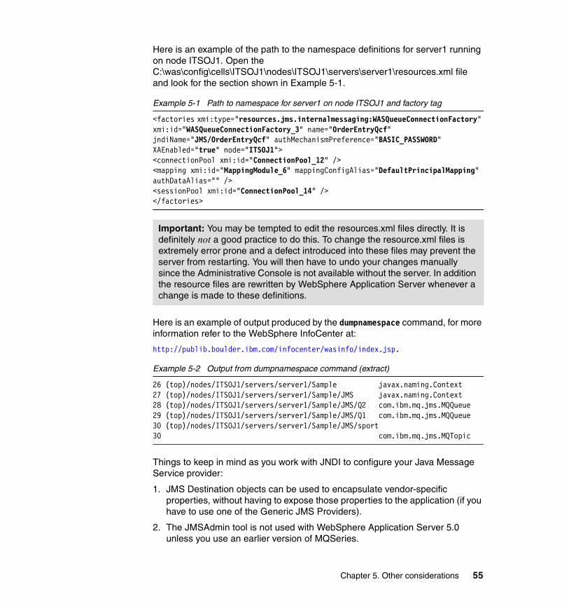
Here is an example of the path to the namespace definitions for server1 running on node ITSOJ1. Open the C:\was\config\cells\ITSOJ1\nodes\ITSOJ1\servers\server1\resources.xml file and look for the section shown in Example 5-1.
Example 5-1 Path to namespace for server1 on node ITSOJ1 and factory tag
<factories xmi:type="resources.jms.internalmessaging:WASQueueConnectionFactory" xmi:id="WASQueueConnectionFactory_3" name="OrderEntryQcf" jndiName="JMS/OrderEntryQcf" authMechanismPreference="BASIC_PASSWORD" XAEnabled="true" node="ITSOJ1"> <connectionPool xmi:id="ConnectionPool_12" /> <mapping xmi:id="MappingModule_6" mappingConfigAlias="DefaultPrincipalMapping" authDataAlias="" /> <sessionPool xmi:id="ConnectionPool_14" /> </factories>
Here is an example of output produced by the dumpnamespace command, for more information refer to the WebSphere InfoCenter at:
http://publib.boulder.ibm.com/infocenter/wasinfo/index.jsp.
Example 5-2 Output from dumpnamespace command (extract)
26 (top)/nodes/ITSOJ1/servers/server1/Sample javax.naming.Context27 (top)/nodes/ITSOJ1/servers/server1/Sample/JMS javax.naming.Context28 (top)/nodes/ITSOJ1/servers/server1/Sample/JMS/Q2 com.ibm.mq.jms.MQQueue29 (top)/nodes/ITSOJ1/servers/server1/Sample/JMS/Q1 com.ibm.mq.jms.MQQueue30 (top)/nodes/ITSOJ1/servers/server1/Sample/JMS/sport30 com.ibm.mq.jms.MQTopic
Things to keep in mind as you work with JNDI to configure your Java Message Service provider:
1. JMS Destination objects can be used to encapsulate vendor-specific properties, without having to expose those properties to the application (if you have to use one of the Generic JMS Providers).
2. The JMSAdmin tool is not used with WebSphere Application Server 5.0 unless you use an earlier version of MQSeries.
Important: You may be tempted to edit the resources.xml files directly. It is definitely not a good practice to do this. To change the resource.xml files is extremely error prone and a defect introduced into these files may prevent the server from restarting. You will then have to undo your changes manually since the Administrative Console is not available without the server. In addition the resource files are rewritten by WebSphere Application Server whenever a change is made to these definitions.
Chapter 5. Other considerations 55
5.3 Design patterns with message-driven beans Today’s best practices suggest that business logic and rules should be located in distinct modules. These classes are typically found in EJBs, Compute nodes of MQI, or in servlets. While the location you choose will naturally depend on your legacy environment and current practices, the addition of messaging to your application server provides some new components appropriate for certain elements of an application’s business logic. These are JMS/XA support and message-driven beans. WebSphere MQ Integration Broker based applications with business rules resident in Compute nodes are another case to consider.
Container managedWith the base JMS/XA support, the J2EE application uses standard JMS calls to process messages, including any responses or outbound messaging. Responses can be handled by an enterprise bean acting as a sender bean, or handled in the enterprise bean that receives the incoming messages. Optionally, this process can use two-phase commit within the scope of a transaction. This level of functionality for asynchronous messaging is called bean-managed messaging, and gives an enterprise bean complete control over the messaging infrastructure, for example for connection and session pool management. The common container has no role in bean-managed messaging.
Message-driven bean managed WebSphere Application Server also supports automatic asynchronous messaging using message-driven beans (a type of enterprise bean defined in the EJB 2.0 specification) and JMS listeners (part of the JMS application server facilities). Messages are automatically retrieved from JMS Destinations, optionally within a transaction, then sent to the message-driven bean in an J2EE application, without the application having to explicitly poll JMS Destinations.
MDBs can handle messages read from JMS Destinations within the scope of a transaction. If transaction handling is specified for a JMS Destination, the JMS listener starts a global transaction before it reads any incoming message from that destination. When the MDB processing has completed, the JMS listener commits or rolls back the transaction (using JTA transaction control).
Support for long-running transactionsThe issue with long-running transactions is simply that when a transaction resource list includes processes that run in human time frames along with machine times, the commit process become far more complex. This question arises in workflow applications of all kinds, for example in the insurance industry where processing claims may entail a long series of processing steps, data collection tasks, evaluations and reviews that vary from claim to claim.
56 WebSphere Application Server and WebSphere MQ Family Integration
Asynchronous messaging such as the Java Message Service supports can provide powerful tools for managing long-running transactions. One of the most difficult aspects of managing LRTs is the need to identify and communicate with system components that vary in number and responsibility and determine when the transaction across all of these resources has been completed. One way to do this is to use an Observer pattern, which works well if you know in advance which nodes in the transaction you have to contact and how to know with certainty you have contacted them. While simple to describe, this turns out to be difficult to do in practice. Often it becomes a matter of deciding how much time may elapse before a resource is considered to be unavailable or not interested. In practice current patterns for describing long-running transactions are often unwieldy to implement and difficult to operate.
In thinking about an LRT using Embedded Messaging and Java Message Service, consider the following elements of the pattern:
� Distributed containers
� Publish/subscribe with Topic Destinations, especially persistent publication within the scope of a JMS/XA transaction
� JMS/XA
� Unit of work, one per request message
� JMS properties, for example TimetoLive
� Response management
5.4 Message providers and transactionsTransaction behavior is container managed in J2EE 1.3 compliant servers.
The effect of transaction context on non-durable subscribersA non-durable subscriber can only be used in the same transactional context (for example, a global transaction or an unspecified transaction context) that existed when the subscriber was created. A non-durable subscriber is invalidated whenever a sharing boundary (in general, a local or global transaction boundary)
Note: An important effect of container-managed transactions is:
1. All messages retrieved from a destination have the same transactional behavior.
2. If non-WebSphere Application Server XA connection factories are used, then the JMS resources are not recovered if the server fails.
Chapter 5. Other considerations 57
is crossed, resulting in a javax.jms.IllegalStateException with the message "Non-durable subscriber invalidated on transaction boundary".
For example, in the following scenario the non-durable subscriber is invalidated at the begin user transaction point. This is because the local transaction context in which the subscriber was created ends when the user transaction begins:
1. ...2. create subscriber3. ...4. begin user transaction5. ...6. complete user transaction7. ...8. use subscriber9. ...
If you want to cache a subscriber (to wait to receive messages that arrived since it was created), then use a durable subscriber (for which this restriction does not apply). Do not cache non-durable subscribers.
5.5 Security In this section, we take a look at some security issues related directly to Embedded Messaging, specifically how to use SSL with Embedded Messaging as discussed in Chapter 15, “WebSphere MQ and SSL scenario” on page 369. Since a complete discussion of security principles is outside the scope of this redbook, you may want to refer to the redbook IBM WebSphere V5.0 Security, WebSphere Handbook Series, SG24-6573.
5.5.1 Basic issuesSecurity of your messages is an important concern in even the simplest applications. A key thing to understand is that WebSphere Application Server 5.0 is rich in features to support security defined at deployment time. In most cases you will not need to embed security services in applications and by and large you can avoid exposing authorization and access control data. This simplifies your deployment because you can apply security after you establish your JMS resource definitions and completed your integration testing. To take full advantage of these capabilities, you should be aware of the rich set of security services and options offered by WebSphere Application Server 5.
58 WebSphere Application Server and WebSphere MQ Family Integration
The well-known three properties of security apply to message-based applications. In general in a secure system we can grant access when we recognize:
� Something the user is� Something the user has� Something the user knows
Of immediate interest here is the fact that JMS messages arriving at a listener port have no client credentials associated with them. Incoming messages are anonymous. It follows that security cannot be based on client credentials. In fact no user ID or client session may exist (no user does exist for a SOAP message, for example). Consequently you must establish your security in a manner that anticipates this fact and still observes the three-properties rule if possible.
In applying your security, consider the following:
� The JMS listener assumes the credentials of the application server process when the message-driven bean is invoked. Consequently all subsequent processing will have these credentials available.
� You can avoid the pitfall of having to store a user ID and password locally on the application server itself, especially not if the machine is exposed to the open Internet.
� You can pass messages through your firewalls using the secure queue to queue capabilities of MQSeries Internet pass-thru (MQIPT). This is discussed further in “WebSphere MQ Internet pass-thru (MQIPT)” on page 60.
� You can pass messages into your DMZ or edge servers using HTTPS and SSL, and you can maintain this level of protection for the life of the message.
� Java Message Service supports a connection type that does not pass logon information, the no arg connection. Using this means there is never any access data (user ID and password) present on the runtime environment on your server. The application credentials are stored in the configuration files of the server, but this file can be physically secured. In particular you can give read access to the server.conf file only to trusted administrators.
5.5.2 Messaging through a firewallWhile almost every application exposed to the Internet will be behind a protocol firewall, it is not unusual to have firewall separate servers between each layer of of a multi-tiered application.
Important: To take effect, you must enable global security on your server. This is done at deployment.
Chapter 5. Other considerations 59
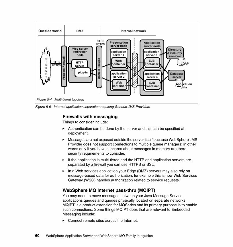
Figure 5-6 Internal application separation requiring Generic JMS Providers
Firewalls with messagingThings to consider include:
� Authentication can be done by the server and this can be specified at deployment.
� Messages are not exposed outside the server itself because WebSphere JMS Provider does not support connections to multiple queue managers; in other words only if you have concerns about messages in memory are there security requirements to consider.
� If the application is multi-tiered and the HTTP and application servers are separated by a firewall you can use HTTPS or SSL.
� In a Web services application your Edge (DMZ) servers may also rely on message-based data for authorization, for example this is how Web Services Gateway (WSG) handles authorization related to service requests.
WebSphere MQ Internet pass-thru (MQIPT)You may need to move messages between your Java Message Service applications queues and queues physically located on separate networks. MQIPT is a product extension for MQSeries and its primary purpose is to enable such connections. Some things MQIPT does that are relevant to Embedded Messaging include:
� Connect remote sites across the Internet.
60 WebSphere Application Server and WebSphere MQ Family Integration
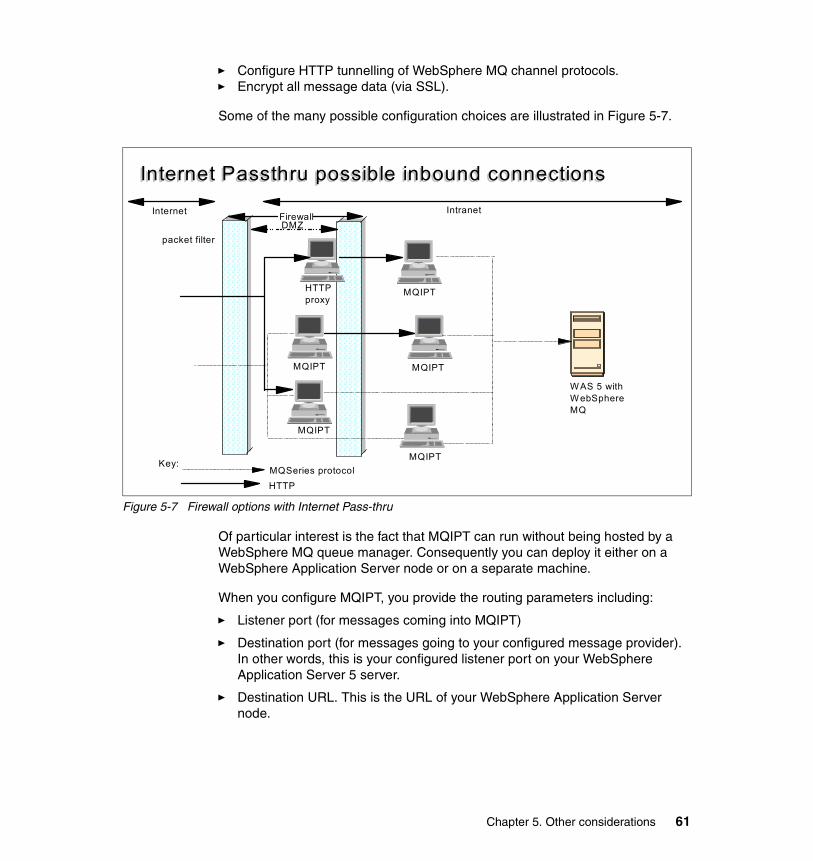
� Configure HTTP tunnelling of WebSphere MQ channel protocols.� Encrypt all message data (via SSL).
Some of the many possible configuration choices are illustrated in Figure 5-7.
Figure 5-7 Firewall options with Internet Pass-thru
Of particular interest is the fact that MQIPT can run without being hosted by a WebSphere MQ queue manager. Consequently you can deploy it either on a WebSphere Application Server node or on a separate machine.
When you configure MQIPT, you provide the routing parameters including:
� Listener port (for messages coming into MQIPT)
� Destination port (for messages going to your configured message provider). In other words, this is your configured listener port on your WebSphere Application Server 5 server.
� Destination URL. This is the URL of your WebSphere Application Server node.
Internet Passthru possible inbound connectionsInternet Passthru possible inbound connections
MQIPT
WAS 5 withWebSphere MQ
MQIPTHTTPproxy
MQIPT
Firewall
Key:MQSeries protocolHTTP
IntranetInternet
MQIPTMQIPT
DMZpacket filter
Chapter 5. Other considerations 61
Documentation on MQIPT is available at:
http://www.software.ibm.com/ts/mqseries/downloads
MQIPT is distributed as SupportPac MS81, which includes the documentation PDF files.
5.5.3 Security issues with message-driven beans (MDBs)You can configure resource security and security permissions for message-driven beans (MDBs). To enable this security support, when you configure security for your application, you must keep in mind you can set:
� Resource security for the message-driven bean to allocate its security method groups.
� Security permissions for the bean create() and onMessage() methods so that they can be accessed by the given application server principal.
5.6 Working with multiple providersYou can configure multiple providers on the same server. In addition:
1. Multiple applications on the same server can have the same names for JMS Destinations. This is because each application looks up the name in its own environment using the container-supplied definition of the name based on the local application JNDI namespace (java:comp/env).
2. More than one JMS Java Message Service provider can be configured per node (although you can only have a single WebSphere JMS Provider on a node) and be active at the same time. If you have both the WebSphere JMS Provider and WebSphere MQ JMS Provider on the same machine, there will be a single copy of the JMS client classes (SupportPac MA88) and the MQ transport code (binaries). These have to be at the same version and patch level.
Note: MQIPT is designed to be used with WebSphere MQ or an earlier version of MQSeries. For this reason we do not recommend it for use with the WebSphere JMS Provider.
Important: If you do configure a full WebSphere Application Server MQ JMS Provider, verify that the version is 5.3 and that fix pack and patch levels are the same as you have for your WebSphere JMS Provider.
62 WebSphere Application Server and WebSphere MQ Family Integration

Chapter 5. Other considerations 63

64 WebSphere Application Server and WebSphere MQ Family Integration
Part 2 Example scenarios
Part 2
© Copyright IBM Corp. 2003. All rights reserved. 65

66 WebSphere Application Server and WebSphere MQ Family Integration
Chapter 6. Introduction to scenarios
This chapter describes a set of problems that a hypothetical business needs to solve in a timely fashion, using technologies that are efficient, reliable, and scalable. From the problem set, we identify some scenarios for which solutions are described in the following chapters. The solutions demonstrate the messaging capabilities in WebSphere Application Server V5 and also the integration of components of the WebSphere MQ family with WebSphere Application Server in the context of the selected scenarios.
6
© Copyright IBM Corp. 2003. All rights reserved. 67
6.1 Brief history of the example companyTZFORU is a company that is in the garments business. It combines innovative designs strategically targeted at market windows with outsourced manufacturing and just-in-time delivery directly to the retailers. The data needed to keep this whole strategy working is obtained from the feedback provided by a nationwide sales force of about 1200 people. Every sales representative is an independent contractor whose only remuneration is commission from sales.
To date, the sales representatives have been calling in their orders that are manually entered into a database. A number of applications are involved in the collection and processing of orders. Typically these applications perform the following tasks:
� Create orders
� Confirm orders
� Fulfill orders
� Append new orders to a data warehouse
� Process information gathered in the data warehouse
� Look for and process specific orders that match certain conditions, for instance, orders that exceed a certain value
� Prepare invoices
� Handle payments
� Track commissions owed to the sales representatives
The current implementation has the following drawbacks:
� A call center to handle the recording of sales is needed. This entails both additional personnel and communications facilities.
� For a company that operates nationwide, the multiple time zones restrict the duration in which sales can be called in.
� If the database fails for a period of time, sales called in during that time could be lost.
� The applications and the database are tightly coupled in the sense that if one of them fails, the others are impacted.
6.2 Impending changes for TZFORUA significant change in the way TZFORU operates has been mandated by new federal regulations. The sales representatives can no longer operate as fully
68 WebSphere Application Server and WebSphere MQ Family Integration
independent contractors. Instead, they need to become full-time employees of the company. This creates the following new problems for the company:
� The company needs to implement human resources and payroll activities to handle the 1200 new employees.
� Communications with the sales force needs to be improved both in terms of the channels and the content in order to motivate the sales force and keep sales from going down.
6.3 Net effect on TZFORUThe two issues confronting TZFORU can be summarized as:
� Antiquated IT infrastructure that is inefficient and failure prone
� Increased demand on the same infrastructure because of the addition of 1200 new employees
The company management realizes that a revamp of the existing IT infrastructure is the best solution to address issues. In terms of architecture, the following two decisions were made:
� To support all access to company processes through Web interfaces
� Where processes are distributed, to loosely couple the involved entities to achieve flexibility of operation and high tolerance of failure
6.4 Typical scenarios in infrastructureIn the process of implementing the new infrastructure, TZFORU will have the scope to fix existing deficiencies. In this section, we select a few of the problems for which we will demonstrate solutions in subsequent chapters. The selected problems are:
� Web enabling of applications� Decoupling of applications from one another and the database� Sending data to multiple destinations� Publish/subscribe model of sharing data� Assuring consistency between distributed resources� Communication with legacy applications
These problems are discussed in greater depth in the following sections.
Chapter 6. Introduction to scenarios 69
6.4.1 Web enabling of applicationsThe order entry application needs to be enabled for access over the Web by the sales representatives. This allows TZFORU to:
� Save cost on the call center� Allow for entry of orders irrespective of the time
The problem of Web enabling is a general one and encompasses all of the applications the geographically dispersed employees of TZFORU need to use. The preceding discussion outlines one situation where the problem exists. However, the same problem may exist in other problem scenarios described below and is discussed in the context of that scenario.
6.4.2 Decoupling applications from each other and the databaseAs noted earlier, in the current implementation the order entry application is tightly coupled with the database. If the database is unavailable or too busy, the order entry process is hindered.
The problem at hand is the decoupling of the order entry application from the database. First, an intermediate store needs to be created that the order entry application populates. Second, a process we will refer to as the order reader process needs to be created that transfers the orders from the intermediate store to the database. This approach also allows for scheduling the loading of orders to the database at a convenient time.
The problem of decoupling an application from the other applications and components of the solution is a general one. The preceding discussion outlines one situation where the problem exists. However, the same problem may exist in other problem scenarios described below and is discussed in the context of that scenario.
70 WebSphere Application Server and WebSphere MQ Family Integration
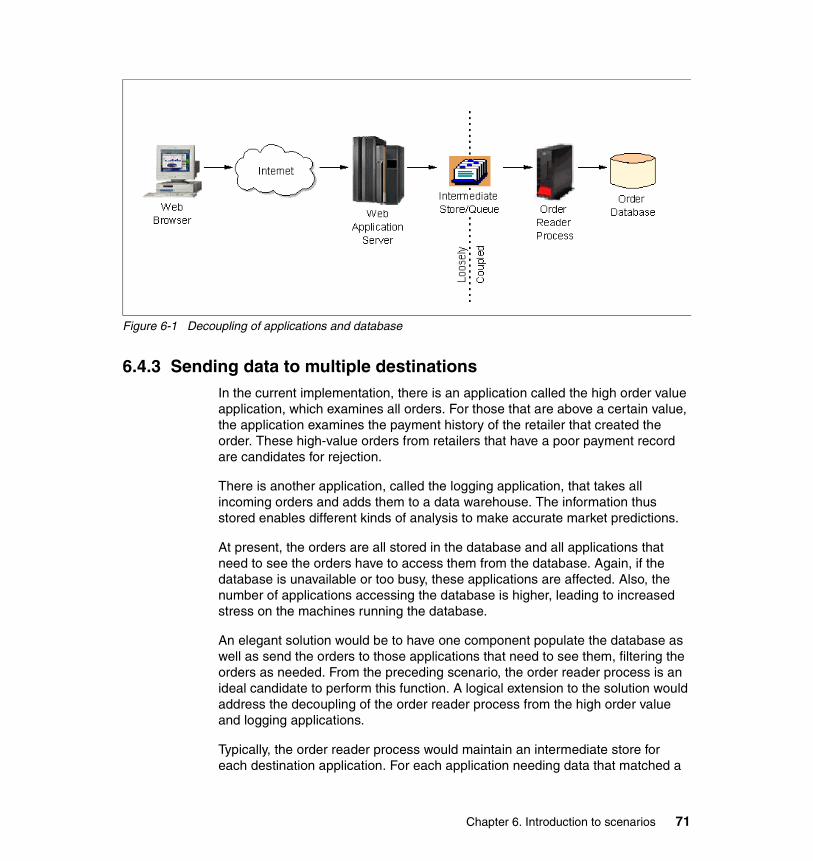
Figure 6-1 Decoupling of applications and database
6.4.3 Sending data to multiple destinationsIn the current implementation, there is an application called the high order value application, which examines all orders. For those that are above a certain value, the application examines the payment history of the retailer that created the order. These high-value orders from retailers that have a poor payment record are candidates for rejection.
There is another application, called the logging application, that takes all incoming orders and adds them to a data warehouse. The information thus stored enables different kinds of analysis to make accurate market predictions.
At present, the orders are all stored in the database and all applications that need to see the orders have to access them from the database. Again, if the database is unavailable or too busy, these applications are affected. Also, the number of applications accessing the database is higher, leading to increased stress on the machines running the database.
An elegant solution would be to have one component populate the database as well as send the orders to those applications that need to see them, filtering the orders as needed. From the preceding scenario, the order reader process is an ideal candidate to perform this function. A logical extension to the solution would address the decoupling of the order reader process from the high order value and logging applications.
Typically, the order reader process would maintain an intermediate store for each destination application. For each application needing data that matched a
Chapter 6. Introduction to scenarios 71
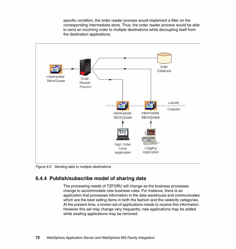
specific condition, the order reader process would implement a filter on the corresponding intermediate store. Thus, the order reader process would be able to send an incoming order to multiple destinations while decoupling itself from the destination applications.
Figure 6-2 Sending data to multiple destinations
6.4.4 Publish/subscribe model of sharing dataThe processing needs of TZFORU will change as the business processes change to accommodate new business rules. For instance, there is an application that processes information in the data warehouse and communicates which are the best selling items in both the fashion and the celebrity categories. At the present time, a known set of applications needs to receive this information. However this set may change very frequently; new applications may be added while existing applications may be removed.
72 WebSphere Application Server and WebSphere MQ Family Integration
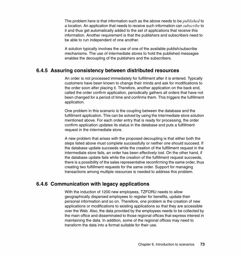
The problem here is that information such as the above needs to be published to a location. An application that needs to receive such information can subscribe to it and thus get automatically added to the set of applications that receive this information. Another requirement is that the publishers and subscribers need to be able to run independent of one another.
A solution typically involves the use of one of the available publish/subscribe mechanisms. The use of intermediate stores to hold the published messages enables the decoupling of the publishers and the subscribers.
6.4.5 Assuring consistency between distributed resourcesAn order is not processed immediately for fulfillment after it is entered. Typically customers have been known to change their minds and ask for modifications to the order soon after placing it. Therefore, another application on the back end, called the order confirm application, periodically gathers all orders that have not been changed for a period of time and confirms them. This triggers the fulfillment application.
One problem in this scenario is the coupling between the database and the fulfillment application. This can be solved by using the intermediate store solution mentioned above. For each order entry that is ready for processing, the order confirm application updates its status in the database and puts a fulfillment request in the intermediate store.
A new problem that arises with the proposed decoupling is that either both the steps listed above must complete successfully or neither one should succeed. If the database update succeeds while the creation of the fulfillment request in the intermediate store fails, an order has been effectively lost. On the other hand, if the database update fails while the creation of the fulfillment request succeeds, there is a possibility of the sales representative reconfirming the same order, thus creating two fulfillment requests for the same order. Support for managing transactions among multiple resources is needed to address this problem.
6.4.6 Communication with legacy applicationsWith the induction of 1200 new employees, TZFORU needs to allow geographically dispersed employees to register for benefits, update their personal information and so on. Therefore, one problem is the creation of new applications or modifications to existing applications so that they are accessible over the Web. Also, the data provided by the employees needs to be collected by the main office and disseminated to those regional offices that express interest in maintaining the data. In addition, some of the regional offices may need to transform the data into a format suitable for their use.
Chapter 6. Introduction to scenarios 73
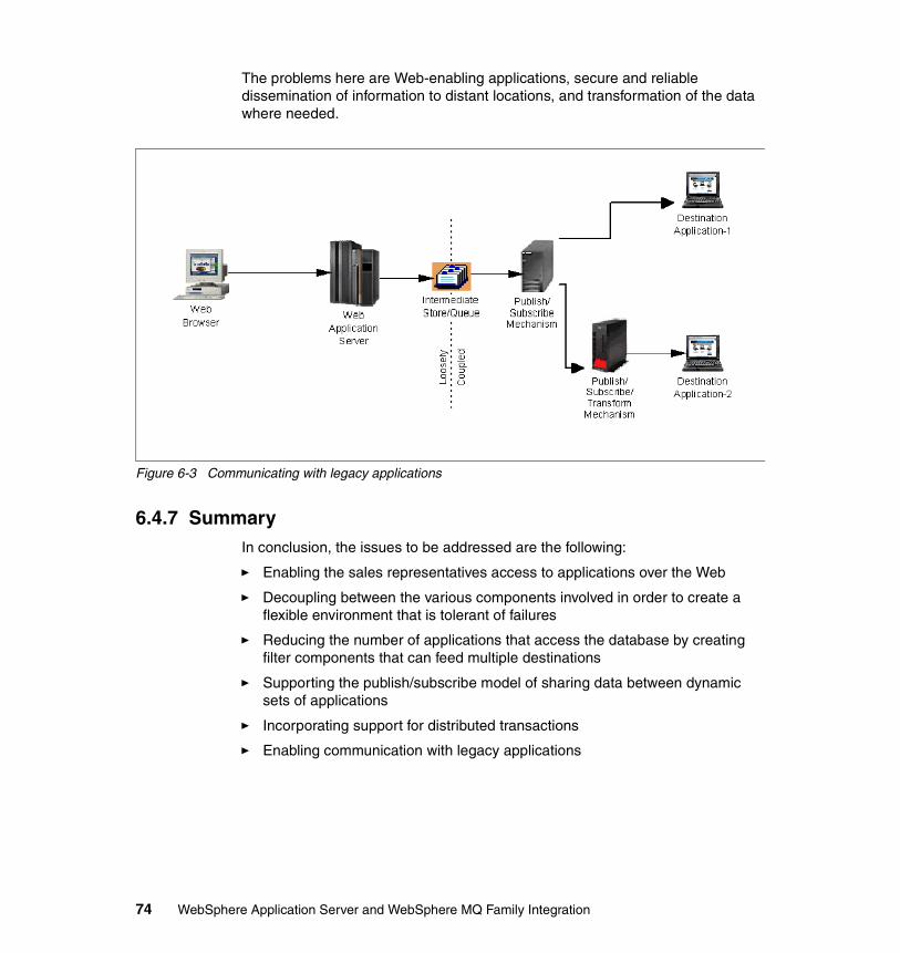
The problems here are Web-enabling applications, secure and reliable dissemination of information to distant locations, and transformation of the data where needed.
Figure 6-3 Communicating with legacy applications
6.4.7 SummaryIn conclusion, the issues to be addressed are the following:
� Enabling the sales representatives access to applications over the Web
� Decoupling between the various components involved in order to create a flexible environment that is tolerant of failures
� Reducing the number of applications that access the database by creating filter components that can feed multiple destinations
� Supporting the publish/subscribe model of sharing data between dynamic sets of applications
� Incorporating support for distributed transactions
� Enabling communication with legacy applications
74 WebSphere Application Server and WebSphere MQ Family Integration
Chapter 7. Base setup
This chapter provides base information on how to set up, configure, and use the products we used for developing and deploying the samples created for the redbook. We regard the information in this chapter as the prerequisite knowledge needed for you to understand and work with the more detailed samples documented later in the redbook.
We describe common tasks that you will perform when using WebSphere Studio Application Developer, WebSphere Application Server, and Embedded Messaging.
7
© Copyright IBM Corp. 2003. All rights reserved. 75
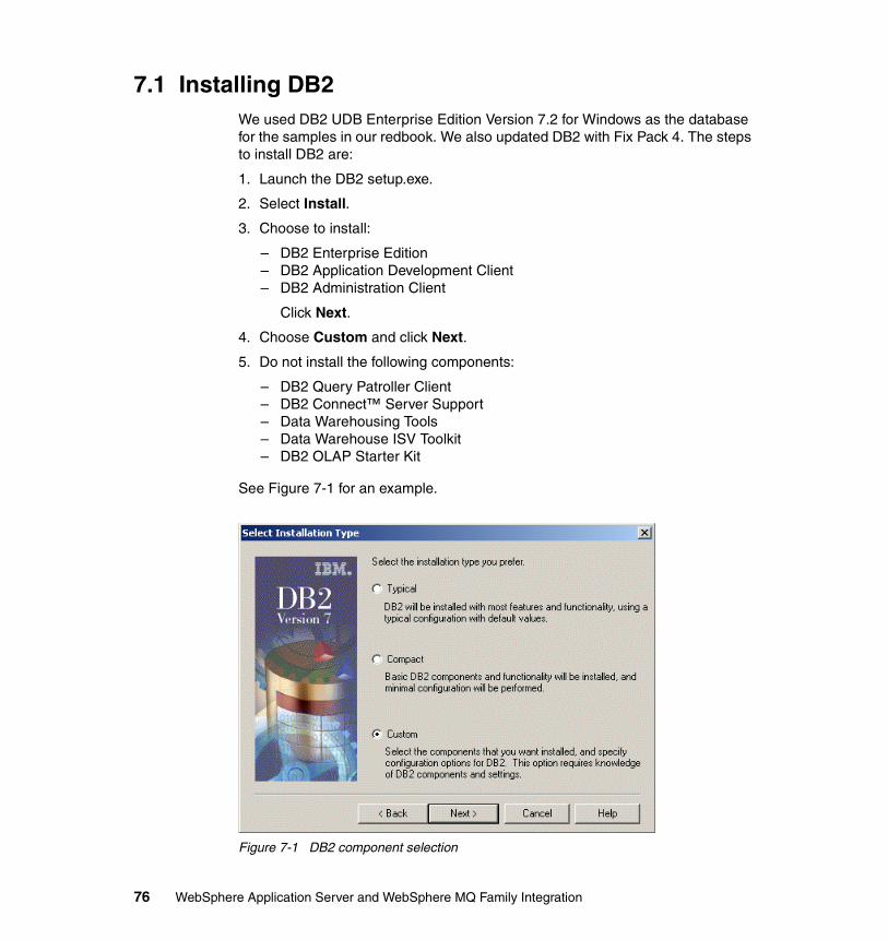
7.1 Installing DB2We used DB2 UDB Enterprise Edition Version 7.2 for Windows as the database for the samples in our redbook. We also updated DB2 with Fix Pack 4. The steps to install DB2 are:
1. Launch the DB2 setup.exe.
2. Select Install.
3. Choose to install:
– DB2 Enterprise Edition– DB2 Application Development Client– DB2 Administration Client
Click Next.
4. Choose Custom and click Next.
5. Do not install the following components:
– DB2 Query Patroller Client– DB2 Connect™ Server Support– Data Warehousing Tools– Data Warehouse ISV Toolkit– DB2 OLAP Starter Kit
See Figure 7-1 for an example.
Figure 7-1 DB2 component selection
76 WebSphere Application Server and WebSphere MQ Family Integration
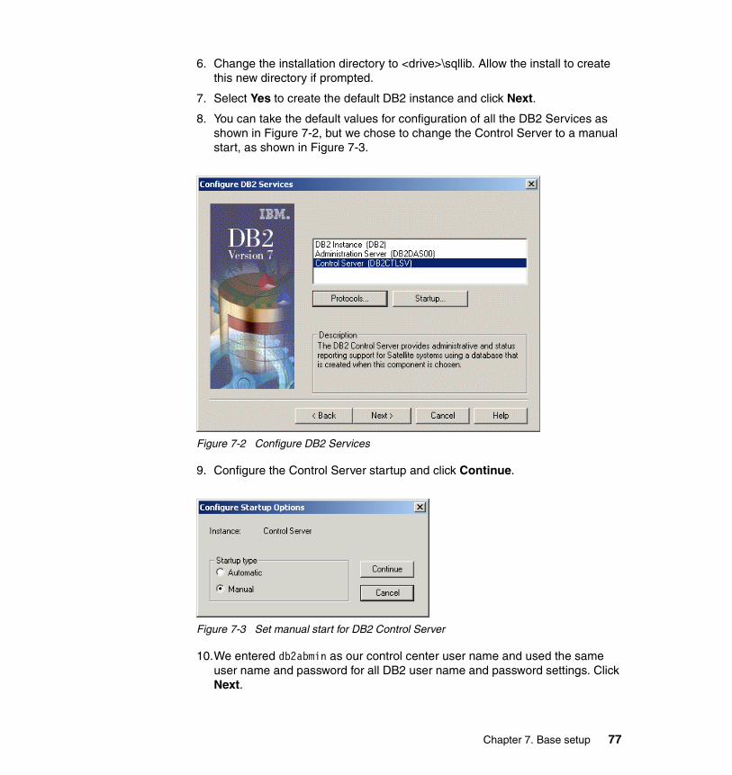
6. Change the installation directory to <drive>\sqllib. Allow the install to create this new directory if prompted.
7. Select Yes to create the default DB2 instance and click Next.
8. You can take the default values for configuration of all the DB2 Services as shown in Figure 7-2, but we chose to change the Control Server to a manual start, as shown in Figure 7-3.
Figure 7-2 Configure DB2 Services
9. Configure the Control Server startup and click Continue.
Figure 7-3 Set manual start for DB2 Control Server
10.We entered db2abmin as our control center user name and used the same user name and password for all DB2 user name and password settings. Click Next.
Chapter 7. Base setup 77
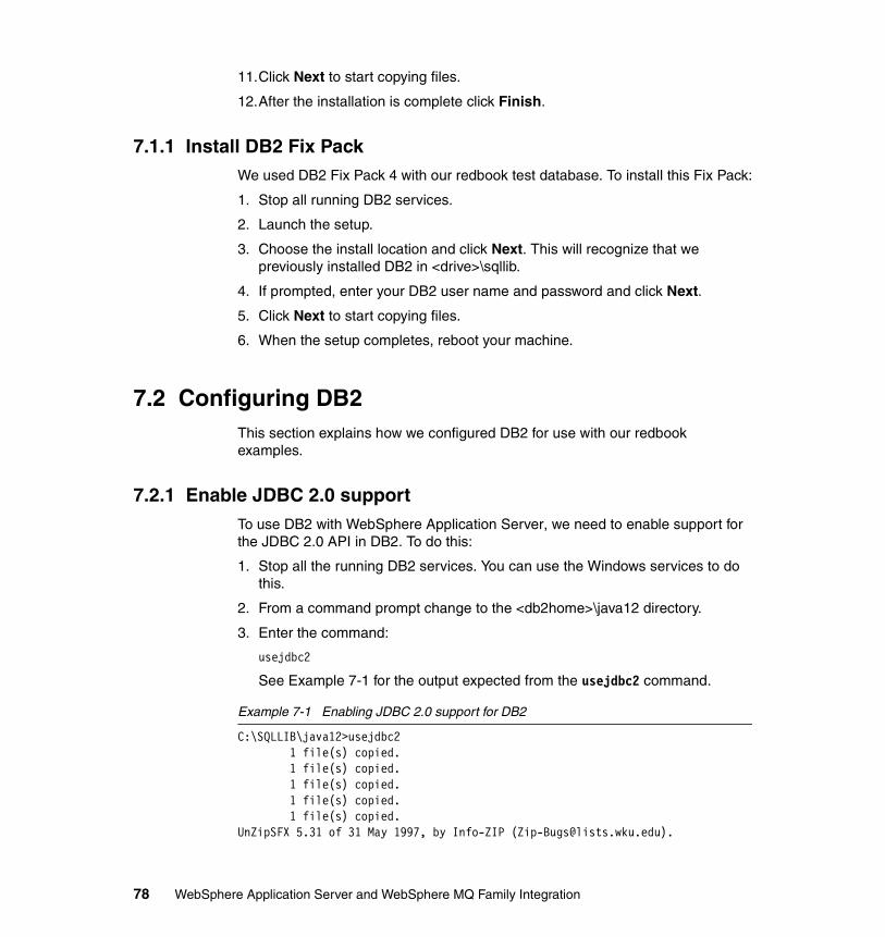
11.Click Next to start copying files.
12.After the installation is complete click Finish.
7.1.1 Install DB2 Fix PackWe used DB2 Fix Pack 4 with our redbook test database. To install this Fix Pack:
1. Stop all running DB2 services.
2. Launch the setup.
3. Choose the install location and click Next. This will recognize that we previously installed DB2 in <drive>\sqllib.
4. If prompted, enter your DB2 user name and password and click Next.
5. Click Next to start copying files.
6. When the setup completes, reboot your machine.
7.2 Configuring DB2This section explains how we configured DB2 for use with our redbook examples.
7.2.1 Enable JDBC 2.0 supportTo use DB2 with WebSphere Application Server, we need to enable support for the JDBC 2.0 API in DB2. To do this:
1. Stop all the running DB2 services. You can use the Windows services to do this.
2. From a command prompt change to the <db2home>\java12 directory.
3. Enter the command:
usejdbc2
See Example 7-1 for the output expected from the usejdbc2 command.
Example 7-1 Enabling JDBC 2.0 support for DB2
C:\SQLLIB\java12>usejdbc2 1 file(s) copied. 1 file(s) copied. 1 file(s) copied. 1 file(s) copied. 1 file(s) copied.UnZipSFX 5.31 of 31 May 1997, by Info-ZIP ([email protected]).
78 WebSphere Application Server and WebSphere MQ Family Integration
inflating: db2java.zip inflating: db2jdbc.dll inflating: db2ccs.exe inflating: db2jd.exe inflating: db2jds.exe 1 file(s) copied. 1 file(s) copied. 1 file(s) copied. 1 file(s) copied. 1 file(s) copied. 1 file(s) copied.
7.3 Installing WebSphere Application ServerWe used WebSphere Application Server Version 5.0 when writing our redbook. The installation of WebSphere was straightforward and we were able to take most default options when installing. The following is an overview of the basic install steps:
1. Start the install and select your installation language.
2. Click Next on the welcome window.
3. Accept the license agreement and click Next.
4. Wait while installation prerequisite checks are run.
5. Choose either a full install or custom install and click Next.
For our redbook a full install is sufficient, but you can also choose a custom install if you wish to see all the components that we installed. See Figure 7-4 on page 80 for an example.
Chapter 7. Base setup 79
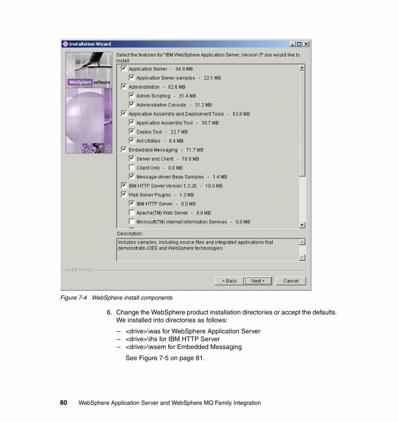
Figure 7-4 WebSphere install components
6. Change the WebSphere product installation directories or accept the defaults. We installed into directories as follows:
– <drive>\was for WebSphere Application Server– <drive>\ihs for IBM HTTP Server– <drive>\wsem for Embedded Messaging
See Figure 7-5 on page 81.
80 WebSphere Application Server and WebSphere MQ Family Integration
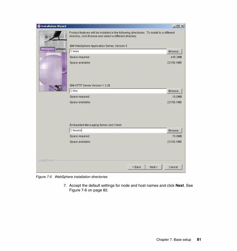
Figure 7-5 WebSphere installation directories
7. Accept the default settings for node and host names and click Next. See Figure 7-6 on page 82.
Chapter 7. Base setup 81
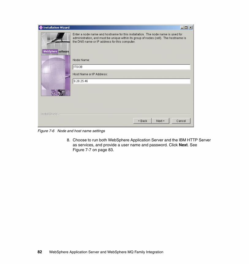
Figure 7-6 Node and host name settings
8. Choose to run both WebSphere Application Server and the IBM HTTP Server as services, and provide a user name and password. Click Next. See Figure 7-7 on page 83.
82 WebSphere Application Server and WebSphere MQ Family Integration
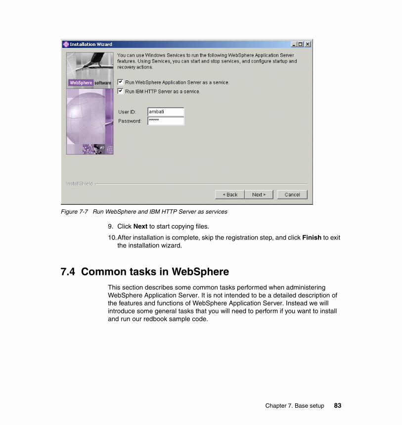
Figure 7-7 Run WebSphere and IBM HTTP Server as services
9. Click Next to start copying files.
10.After installation is complete, skip the registration step, and click Finish to exit the installation wizard.
7.4 Common tasks in WebSphereThis section describes some common tasks performed when administering WebSphere Application Server. It is not intended to be a detailed description of the features and functions of WebSphere Application Server. Instead we will introduce some general tasks that you will need to perform if you want to install and run our redbook sample code.
Chapter 7. Base setup 83
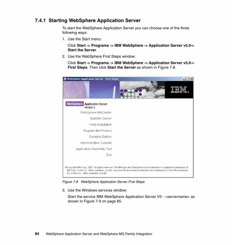
7.4.1 Starting WebSphere Application ServerTo start the WebSphere Application Server you can choose one of the three following ways:
1. Use the Start menu:
Click Start -> Programs -> IBM WebSphere -> Application Server v5.0-> Start the Server.
2. Use the WebSphere First Steps window:
Click Start -> Programs -> IBM WebSphere -> Application Server v5.0-> First Steps. Then click Start the Server as shown in Figure 7-8.
Figure 7-8 WebSphere Application Server First Steps
3. Use the Windows services window:
Start the service IBM WebSphere Application Server V5 - <servername> as shown in Figure 7-9 on page 85.
84 WebSphere Application Server and WebSphere MQ Family Integration
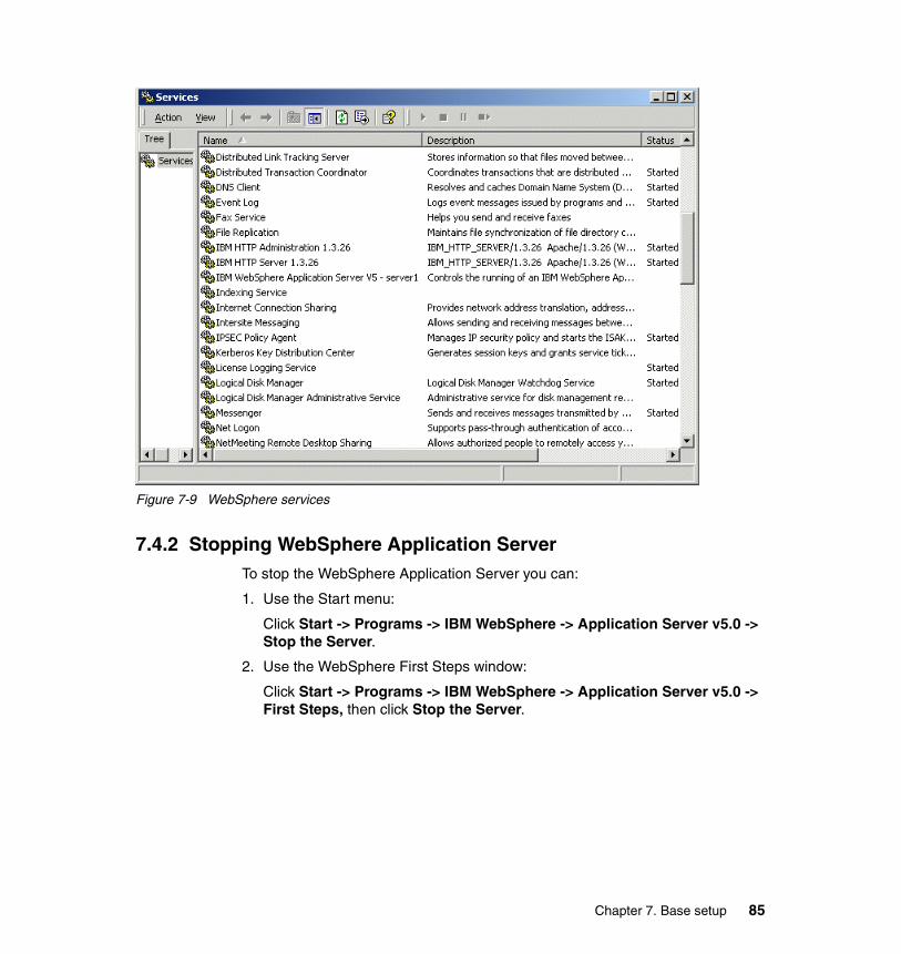
Figure 7-9 WebSphere services
7.4.2 Stopping WebSphere Application ServerTo stop the WebSphere Application Server you can:
1. Use the Start menu:
Click Start -> Programs -> IBM WebSphere -> Application Server v5.0 -> Stop the Server.
2. Use the WebSphere First Steps window:
Click Start -> Programs -> IBM WebSphere -> Application Server v5.0 -> First Steps, then click Stop the Server.
Chapter 7. Base setup 85
7.4.3 Starting the WebSphere Administrative ConsoleThe WebSphere Administrative Console is used to administer the WebSphere Application Server environment. To start the WebSphere Administrative Console, ensure that the WebSphere Application Server is running and then you can:
1. Use the Start menu:
Click Start -> Programs -> IBM WebSphere -> Application Server v5.0 -> Administrative Console.
2. Use the WebSphere First Steps window:
Click Start -> Programs -> IBM WebSphere -> Application Server v5.0 -> First Steps. Then click Administrative Console.
3. Use a Web browser:
Enter the URL: <hostname>:9090/admin
Figure 7-10 on page 87 shows the logon window for the WebSphere Administrative Console. As explained on this window, security is not enabled by default so any user ID can be provided at logon. The user ID does not have to exist, does not require a password, and does not need to be a user ID of a user in the local user registry. It is only used to track user-specific changes to configuration data.
86 WebSphere Application Server and WebSphere MQ Family Integration
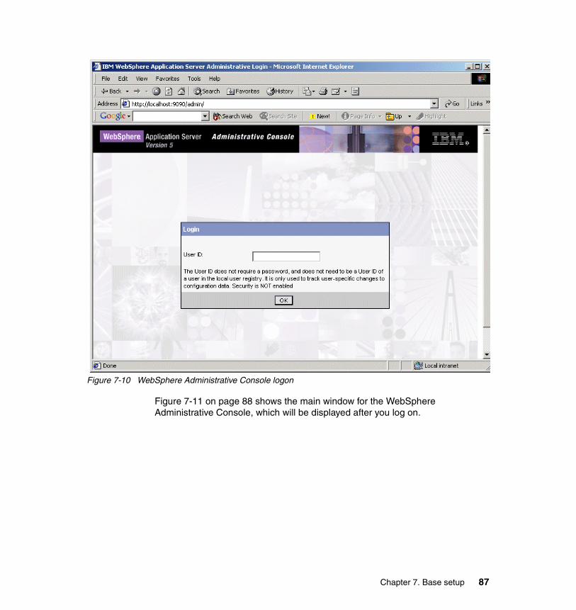
Figure 7-10 WebSphere Administrative Console logon
Figure 7-11 on page 88 shows the main window for the WebSphere Administrative Console, which will be displayed after you log on.
Chapter 7. Base setup 87
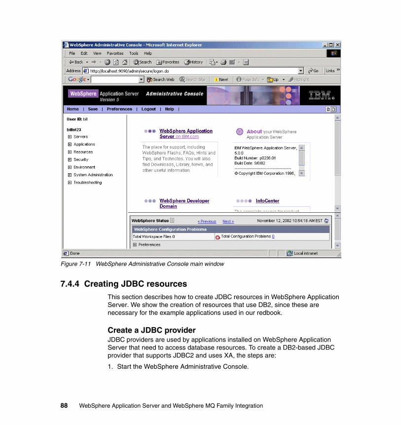
Figure 7-11 WebSphere Administrative Console main window
7.4.4 Creating JDBC resourcesThis section describes how to create JDBC resources in WebSphere Application Server. We show the creation of resources that use DB2, since these are necessary for the example applications used in our redbook.
Create a JDBC providerJDBC providers are used by applications installed on WebSphere Application Server that need to access database resources. To create a DB2-based JDBC provider that supports JDBC2 and uses XA, the steps are:
1. Start the WebSphere Administrative Console.
88 WebSphere Application Server and WebSphere MQ Family Integration
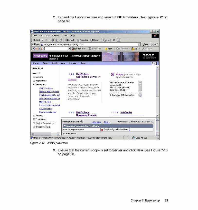
2. Expand the Resources tree and select JDBC Providers. See Figure 7-12 on page 89.
Figure 7-12 JDBC providers
3. Ensure that the current scope is set to Server and click New. See Figure 7-13 on page 90.
Chapter 7. Base setup 89
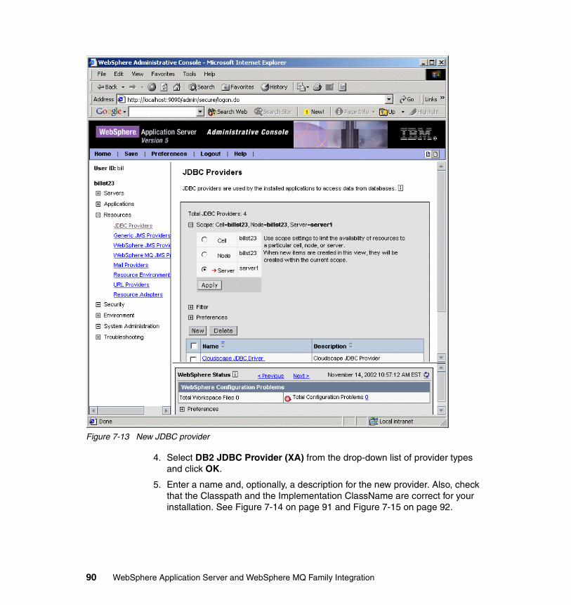
Figure 7-13 New JDBC provider
4. Select DB2 JDBC Provider (XA) from the drop-down list of provider types and click OK.
5. Enter a name and, optionally, a description for the new provider. Also, check that the Classpath and the Implementation ClassName are correct for your installation. See Figure 7-14 on page 91 and Figure 7-15 on page 92.
90 WebSphere Application Server and WebSphere MQ Family Integration
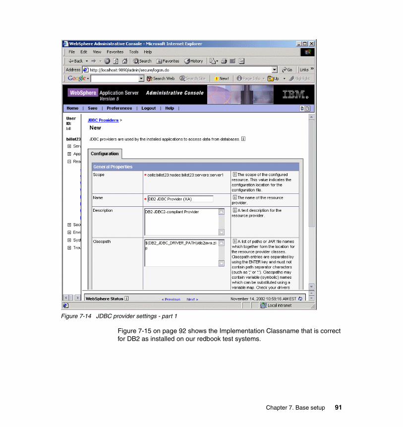
Figure 7-14 JDBC provider settings - part 1
Figure 7-15 on page 92 shows the Implementation Classname that is correct for DB2 as installed on our redbook test systems.
Chapter 7. Base setup 91
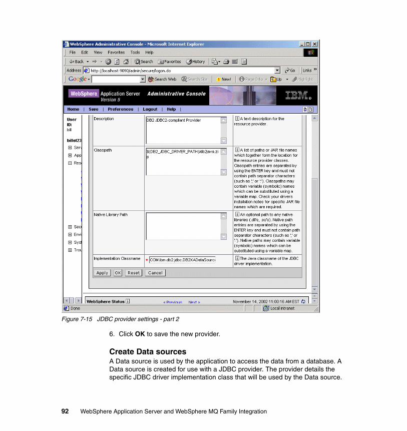
Figure 7-15 JDBC provider settings - part 2
6. Click OK to save the new provider.
Create Data sourcesA Data source is used by the application to access the data from a database. A Data source is created for use with a JDBC provider. The provider details the specific JDBC driver implementation class that will be used by the Data source.
92 WebSphere Application Server and WebSphere MQ Family Integration
To create a Data source to use the DB2 JDBC provider that we created in “Create a JDBC provider” on page 88, the steps are:
1. Start the WebSphere Administrative Console.
2. Expand the Resources tree and select JDBC Providers.
3. Select the JDBC provider for which you want to create a Data source.
4. Click New as shown in Figure 7-16 on page 94.
Chapter 7. Base setup 93
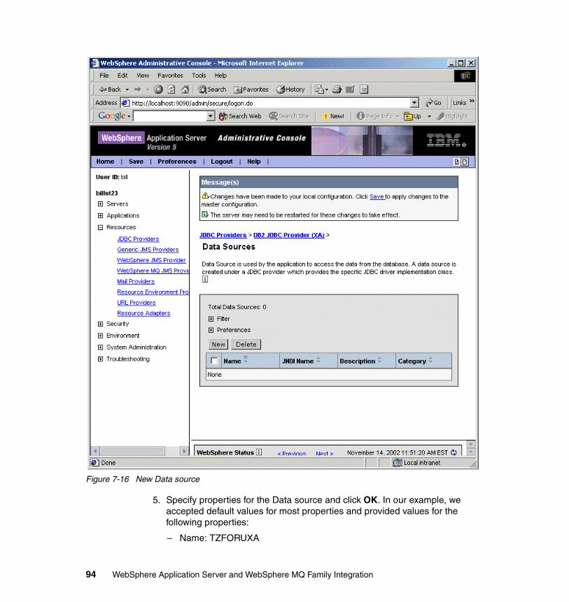
Figure 7-16 New Data source
5. Specify properties for the Data source and click OK. In our example, we accepted default values for most properties and provided values for the following properties:
– Name: TZFORUXA
94 WebSphere Application Server and WebSphere MQ Family Integration
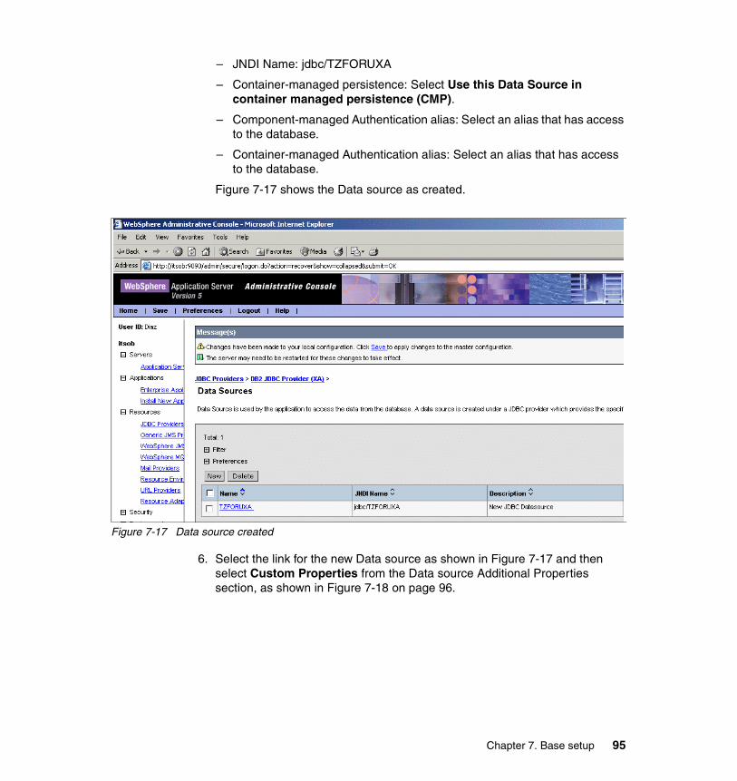
– JNDI Name: jdbc/TZFORUXA
– Container-managed persistence: Select Use this Data Source in container managed persistence (CMP).
– Component-managed Authentication alias: Select an alias that has access to the database.
– Container-managed Authentication alias: Select an alias that has access to the database.
Figure 7-17 shows the Data source as created.
Figure 7-17 Data source created
6. Select the link for the new Data source as shown in Figure 7-17 and then select Custom Properties from the Data source Additional Properties section, as shown in Figure 7-18 on page 96.
Chapter 7. Base setup 95
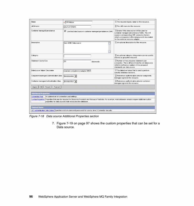
Figure 7-18 Data source Additional Properties section
7. Figure 7-19 on page 97 shows the custom properties that can be set for a Data source.
96 WebSphere Application Server and WebSphere MQ Family Integration
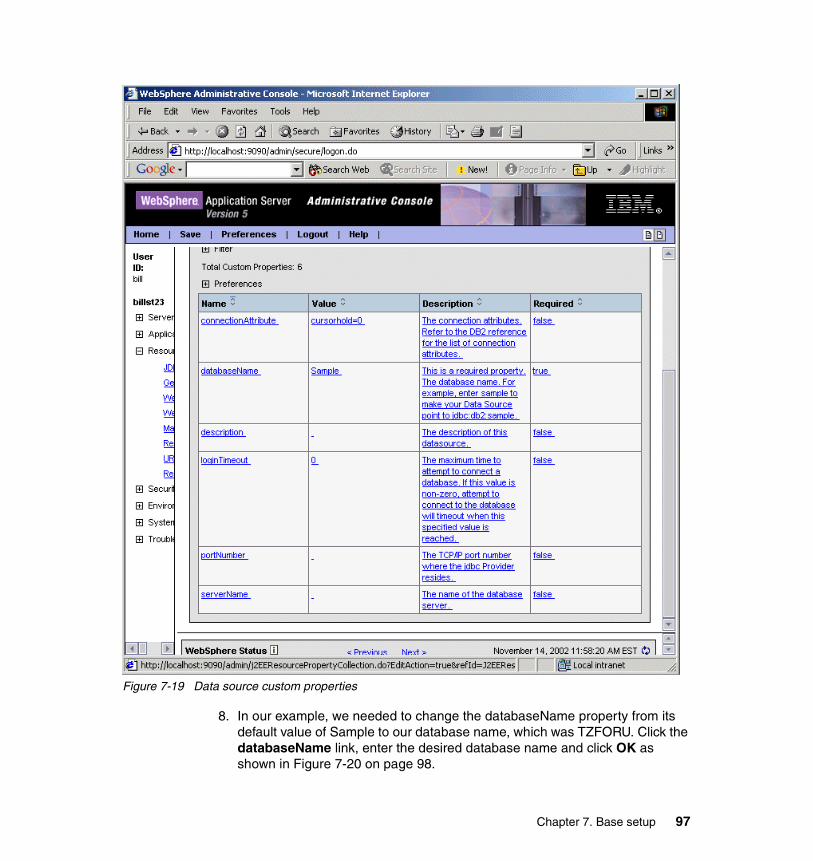
Figure 7-19 Data source custom properties
8. In our example, we needed to change the databaseName property from its default value of Sample to our database name, which was TZFORU. Click the databaseName link, enter the desired database name and click OK as shown in Figure 7-20 on page 98.
Chapter 7. Base setup 97
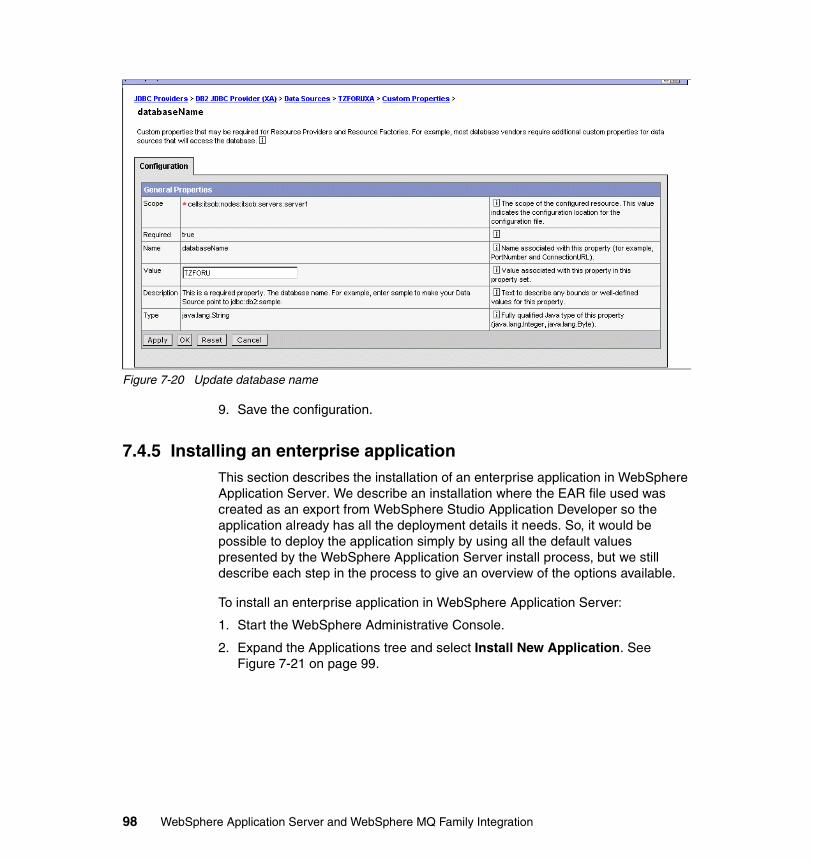
Figure 7-20 Update database name
9. Save the configuration.
7.4.5 Installing an enterprise applicationThis section describes the installation of an enterprise application in WebSphere Application Server. We describe an installation where the EAR file used was created as an export from WebSphere Studio Application Developer so the application already has all the deployment details it needs. So, it would be possible to deploy the application simply by using all the default values presented by the WebSphere Application Server install process, but we still describe each step in the process to give an overview of the options available.
To install an enterprise application in WebSphere Application Server:
1. Start the WebSphere Administrative Console.
2. Expand the Applications tree and select Install New Application. See Figure 7-21 on page 99.
98 WebSphere Application Server and WebSphere MQ Family Integration
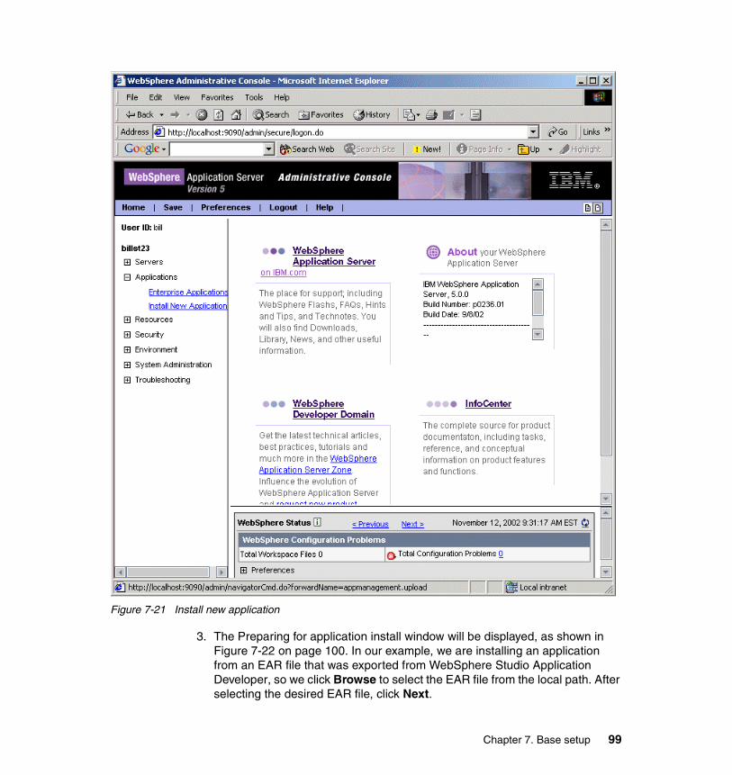
Figure 7-21 Install new application
3. The Preparing for application install window will be displayed, as shown in Figure 7-22 on page 100. In our example, we are installing an application from an EAR file that was exported from WebSphere Studio Application Developer, so we click Browse to select the EAR file from the local path. After selecting the desired EAR file, click Next.
Chapter 7. Base setup 99
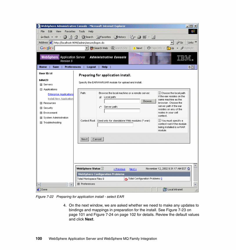
Figure 7-22 Preparing for application install - select EAR
4. On the next window, we are asked whether we need to make any updates to bindings and mappings in preparation for the install. See Figure 7-23 on page 101 and Figure 7-24 on page 102 for details. Review the default values and click Next.
100 WebSphere Application Server and WebSphere MQ Family Integration
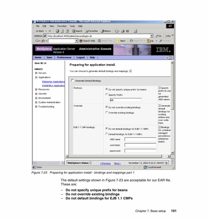
Figure 7-23 Preparing for application install - bindings and mappings part 1
The default settings shown in Figure 7-23 are acceptable for our EAR file. These are:
– Do not specify unique prefix for beans– Do not override existing bindings– Do not default bindings for EJB 1.1 CMPs
Chapter 7. Base setup 101
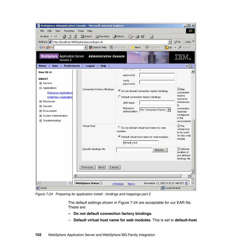
Figure 7-24 Preparing for application install - bindings and mappings part 2
The default settings shown in Figure 7-24 are acceptable for our EAR file. These are:
– Do not default connection factory bindings.
– Default virtual host name for web modules. This is set to default-host.
102 WebSphere Application Server and WebSphere MQ Family Integration

5. The pane Step 1: Provide options to perform the installation, as shown in Figure 7-25 on page 104, is displayed. The default settings from our EAR include:
– Distribute Application.
– Create MBeans for Resources.
The application name will also default to that from the EAR file.
Click Next to continue.
Chapter 7. Base setup 103
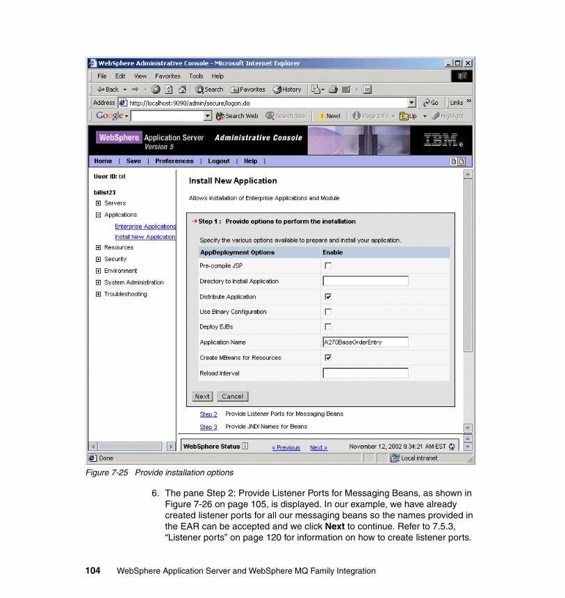
Figure 7-25 Provide installation options
6. The pane Step 2: Provide Listener Ports for Messaging Beans, as shown in Figure 7-26 on page 105, is displayed. In our example, we have already created listener ports for all our messaging beans so the names provided in the EAR can be accepted and we click Next to continue. Refer to 7.5.3, “Listener ports” on page 120 for information on how to create listener ports.
104 WebSphere Application Server and WebSphere MQ Family Integration
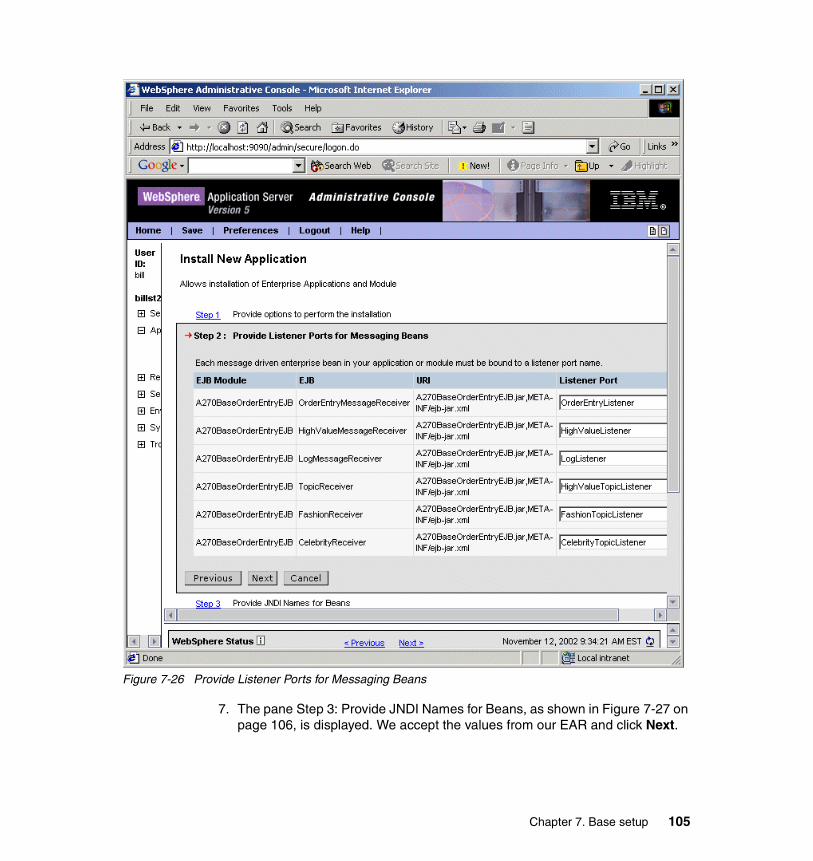
Figure 7-26 Provide Listener Ports for Messaging Beans
7. The pane Step 3: Provide JNDI Names for Beans, as shown in Figure 7-27 on page 106, is displayed. We accept the values from our EAR and click Next.
Chapter 7. Base setup 105

Figure 7-27 Provide JNDI Names for Beans
8. The pane Step 4: Provide default data source mapping for modules containing 2.0 entity beans is displayed. We have one 2.0 EJB called A270BaseOrderEtryEJB in our example EAR file and this is associated with a Data source that has the JNDI name of jdbc/TZFORUXA. We have previously
106 WebSphere Application Server and WebSphere MQ Family Integration
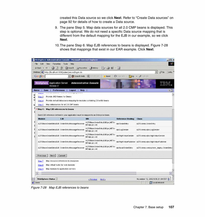
created this Data source so we click Next. Refer to “Create Data sources” on page 92 for details of how to create a Data source.
9. The pane Step 5: Map data sources for all 2.0 CMP beans is displayed. This step is optional. We do not need a specific Data source mapping that is different from the default mapping for the EJB in our example, so we click Next.
10.The pane Step 6: Map EJB references to beans is displayed. Figure 7-28 shows that mappings that exist in our EAR example. Click Next.
Figure 7-28 Map EJB references to beans
Chapter 7. Base setup 107
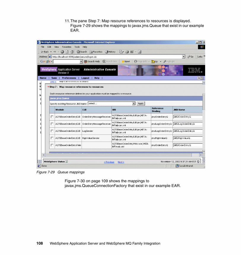
11.The pane Step 7: Map resource references to resources is displayed. Figure 7-29 shows the mappings to javax.jms.Queue that exist in our example EAR.
Figure 7-29 Queue mappings
Figure 7-30 on page 109 shows the mappings to javax.jms.QueueConnectionFactory that exist in our example EAR.
108 WebSphere Application Server and WebSphere MQ Family Integration
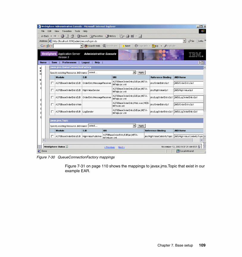
Figure 7-30 QueueConnectionFactory mappings
Figure 7-31 on page 110 shows the mappings to javax.jms.Topic that exist in our example EAR.
Chapter 7. Base setup 109
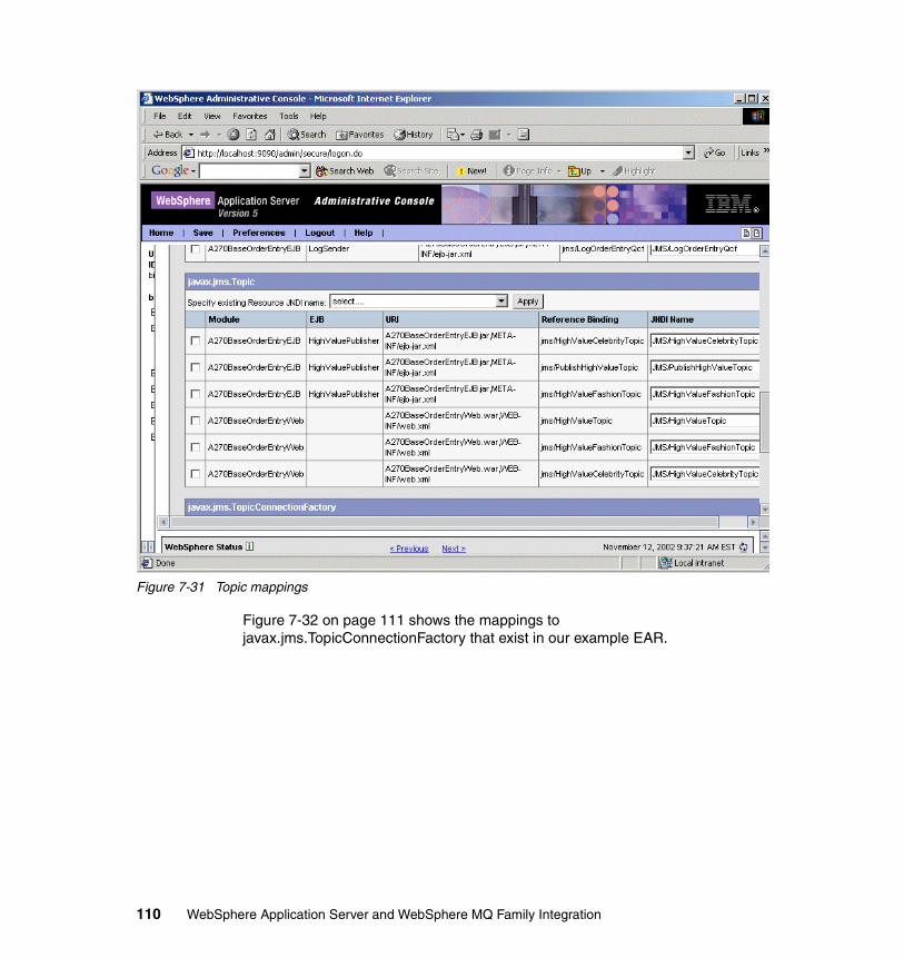
Figure 7-31 Topic mappings
Figure 7-32 on page 111 shows the mappings to javax.jms.TopicConnectionFactory that exist in our example EAR.
110 WebSphere Application Server and WebSphere MQ Family Integration
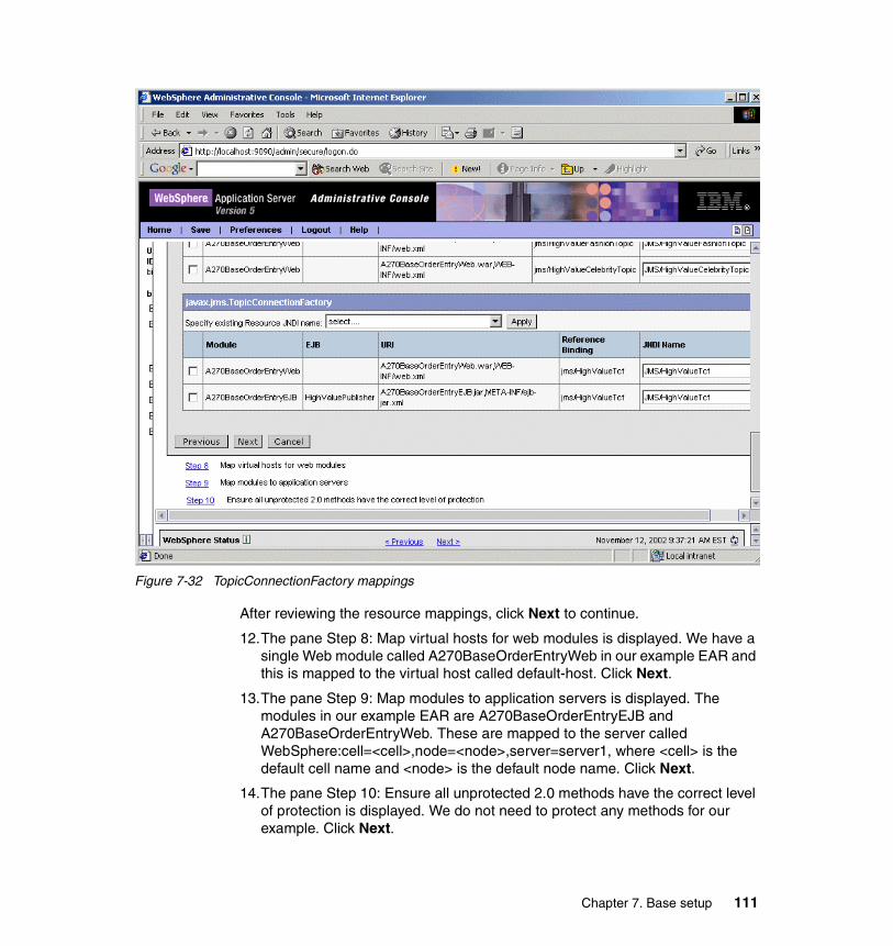
Figure 7-32 TopicConnectionFactory mappings
After reviewing the resource mappings, click Next to continue.
12.The pane Step 8: Map virtual hosts for web modules is displayed. We have a single Web module called A270BaseOrderEntryWeb in our example EAR and this is mapped to the virtual host called default-host. Click Next.
13.The pane Step 9: Map modules to application servers is displayed. The modules in our example EAR are A270BaseOrderEntryEJB and A270BaseOrderEntryWeb. These are mapped to the server called WebSphere:cell=<cell>,node=<node>,server=server1, where <cell> is the default cell name and <node> is the default node name. Click Next.
14.The pane Step 10: Ensure all unprotected 2.0 methods have the correct level of protection is displayed. We do not need to protect any methods for our example. Click Next.
Chapter 7. Base setup 111
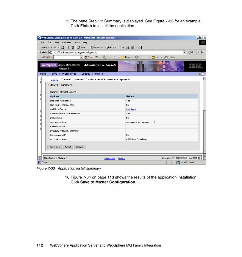
15.The pane Step 11: Summary is displayed. See Figure 7-33 for an example. Click Finish to install the application.
Figure 7-33 Application install summary
16.Figure 7-34 on page 113 shows the results of the application installation. Click Save to Master Configuration.
112 WebSphere Application Server and WebSphere MQ Family Integration
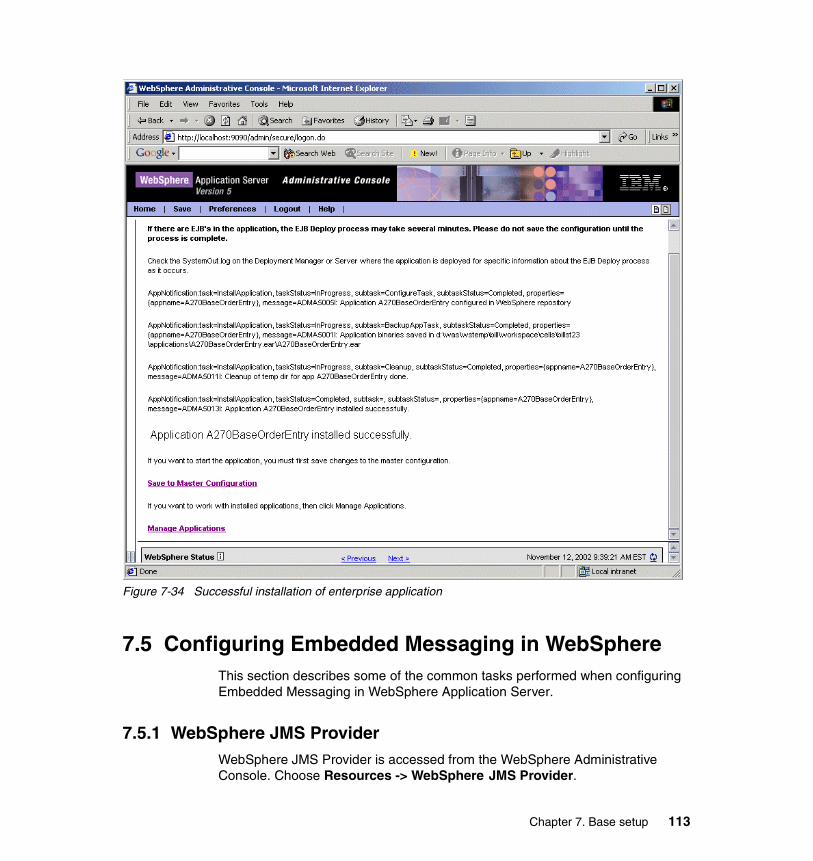
Figure 7-34 Successful installation of enterprise application
7.5 Configuring Embedded Messaging in WebSphereThis section describes some of the common tasks performed when configuring Embedded Messaging in WebSphere Application Server.
7.5.1 WebSphere JMS ProviderWebSphere JMS Provider is accessed from the WebSphere Administrative Console. Choose Resources -> WebSphere JMS Provider.
Chapter 7. Base setup 113
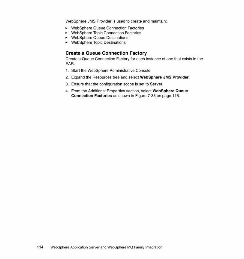
WebSphere JMS Provider is used to create and maintain:
� WebSphere Queue Connection Factories� WebSphere Topic Connection Factories� WebSphere Queue Destinations� WebSphere Topic Destinations
Create a Queue Connection FactoryCreate a Queue Connection Factory for each instance of one that exists in the EAR.
1. Start the WebSphere Administrative Console.
2. Expand the Resources tree and select WebSphere JMS Provider.
3. Ensure that the configuration scope is set to Server.
4. From the Additional Properties section, select WebSphere Queue Connection Factories as shown in Figure 7-35 on page 115.
114 WebSphere Application Server and WebSphere MQ Family Integration
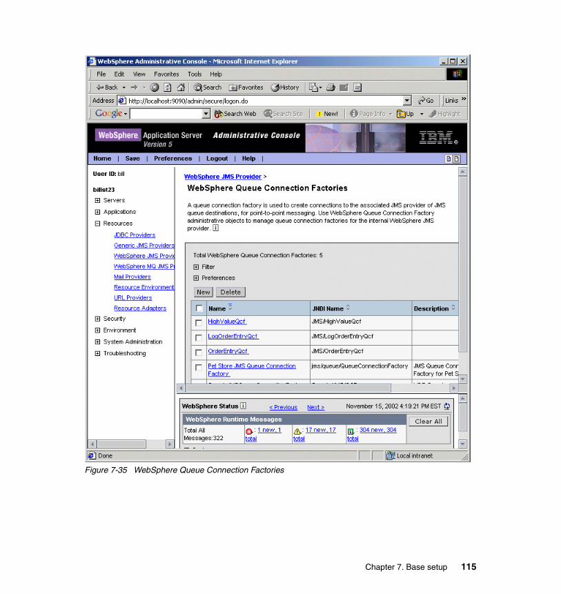
Figure 7-35 WebSphere Queue Connection Factories
Chapter 7. Base setup 115
5. Click New and provide properties for the Queue Connection Factory. Figure 7-36 shows an example of a QCF definition.
Figure 7-36 Queue Connection Factory properties
6. Click OK and save your WebSphere configuration.
Create a Topic Connection FactoryCreate a Topic Connection Factory for each instance of one that exists in the EAR. In our example, there is just one.
1. Start the WebSphere Administrative Console.
2. Expand the Resources tree and select WebSphere JMS Provider.
3. Ensure that the configuration scope is set to Server.
4. From the Additional Properties section select WebSphere Topic Connection Factories.
Important: When we wrote this redbook we found that the WebSphere Administrative Console would often fail to show the full list of existing JMS resources, such as Queue Connection Factories, when first loaded. We found that refreshing the window or reloading the window by reselecting WebSphere JMS Provider would allow the full list to be displayed.
116 WebSphere Application Server and WebSphere MQ Family Integration
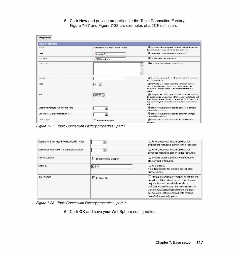
5. Click New and provide properties for the Topic Connection Factory. Figure 7-37 and Figure 7-38 are examples of a TCF definition.
Figure 7-37 Topic Connection Factory properties - part 1
Figure 7-38 Topic Connection Factory properties - part 2
6. Click OK and save your WebSphere configuration.
Chapter 7. Base setup 117
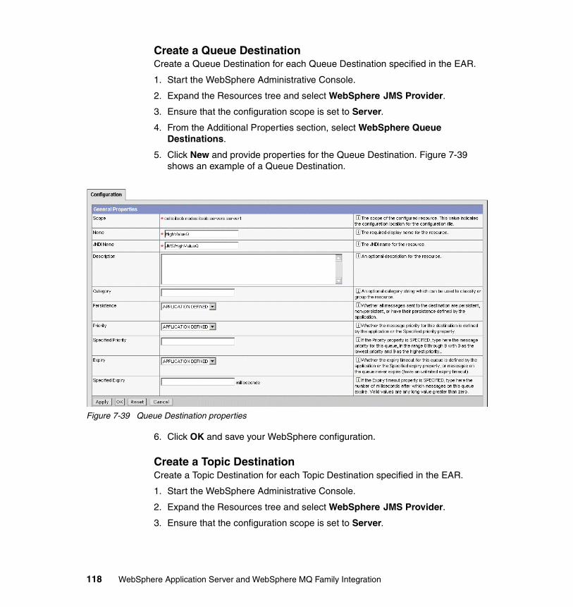
Create a Queue DestinationCreate a Queue Destination for each Queue Destination specified in the EAR.
1. Start the WebSphere Administrative Console.
2. Expand the Resources tree and select WebSphere JMS Provider.
3. Ensure that the configuration scope is set to Server.
4. From the Additional Properties section, select WebSphere Queue Destinations.
5. Click New and provide properties for the Queue Destination. Figure 7-39 shows an example of a Queue Destination.
Figure 7-39 Queue Destination properties
6. Click OK and save your WebSphere configuration.
Create a Topic Destination Create a Topic Destination for each Topic Destination specified in the EAR.
1. Start the WebSphere Administrative Console.
2. Expand the Resources tree and select WebSphere JMS Provider.
3. Ensure that the configuration scope is set to Server.
118 WebSphere Application Server and WebSphere MQ Family Integration
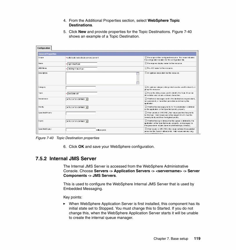
4. From the Additional Properties section, select WebSphere Topic Destinations.
5. Click New and provide properties for the Topic Destinations. Figure 7-40 shows an example of a Topic Destination.
Figure 7-40 Topic Destination properties
6. Click OK and save your WebSphere configuration.
7.5.2 Internal JMS ServerThe Internal JMS Server is accessed from the WebSphere Administrative Console. Choose Servers -> Application Servers -> <servername> -> Server Components -> JMS Servers.
This is used to configure the WebSphere Internal JMS Server that is used by Embedded Messaging.
Key points:
� When WebSphere Application Server is first installed, this component has its initial state set to Stopped. You must change this to Started. If you do not change this, when the WebSphere Application Server starts it will be unable to create the internal queue manager.
Chapter 7. Base setup 119
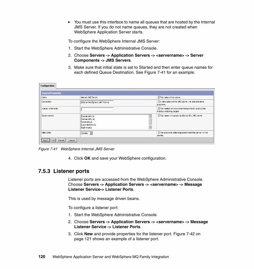
� You must use this interface to name all queues that are hosted by the Internal JMS Server. If you do not name queues, they are not created when WebSphere Application Server starts.
To configure the WebSphere Internal JMS Server:
1. Start the WebSphere Administrative Console.
2. Choose Servers -> Application Servers -> <servername> -> Server Components -> JMS Servers.
3. Make sure that initial state is set to Started and then enter queue names for each defined Queue Destination. See Figure 7-41 for an example.
Figure 7-41 WebSphere Internal JMS Server
4. Click OK and save your WebSphere configuration.
7.5.3 Listener portsListener ports are accessed from the WebSphere Administrative Console. Choose Servers -> Application Servers -> <servername> -> Message Listener Service-> Listener Ports.
This is used by message driven beans.
To configure a listener port:
1. Start the WebSphere Administrative Console.
2. Choose Servers -> Application Servers -> <servername> -> Message Listener Service -> Listener Ports.
3. Click New and provide properties for the listener port. Figure 7-42 on page 121 shows an example of a listener port.
120 WebSphere Application Server and WebSphere MQ Family Integration
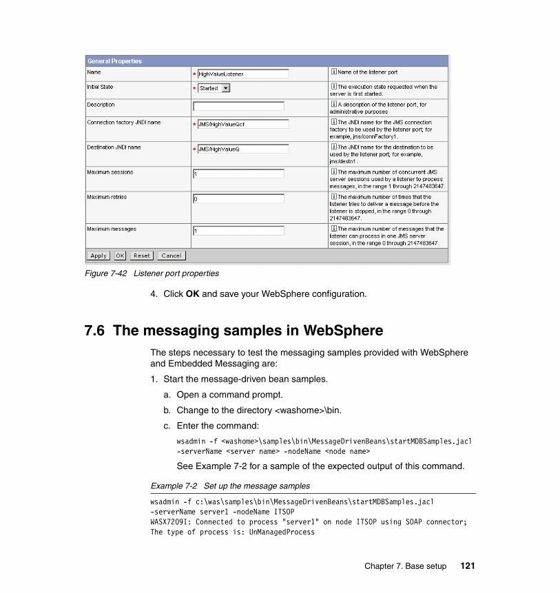
Figure 7-42 Listener port properties
4. Click OK and save your WebSphere configuration.
7.6 The messaging samples in WebSphereThe steps necessary to test the messaging samples provided with WebSphere and Embedded Messaging are:
1. Start the message-driven bean samples.
a. Open a command prompt.
b. Change to the directory <washome>\bin.
c. Enter the command:
wsadmin -f <washome>\samples\bin\MessageDrivenBeans\startMDBSamples.jacl -serverName <server name> -nodeName <node name>
See Example 7-2 for a sample of the expected output of this command.
Example 7-2 Set up the message samples
wsadmin -f c:\was\samples\bin\MessageDrivenBeans\startMDBSamples.jacl -serverName server1 -nodeName ITSOPWASX7209I: Connected to process "server1" on node ITSOP using SOAP connector; The type of process is: UnManagedProcess
Chapter 7. Base setup 121
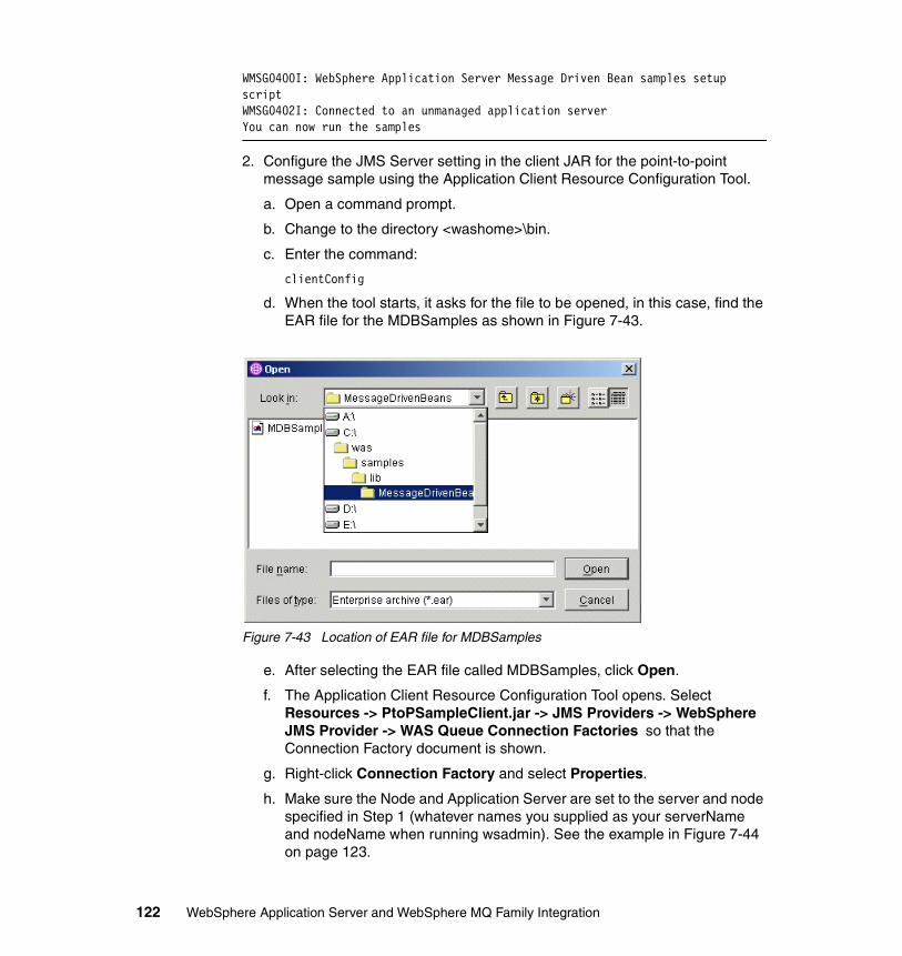
WMSG0400I: WebSphere Application Server Message Driven Bean samples setup scriptWMSG0402I: Connected to an unmanaged application serverYou can now run the samples
2. Configure the JMS Server setting in the client JAR for the point-to-point message sample using the Application Client Resource Configuration Tool.
a. Open a command prompt.
b. Change to the directory <washome>\bin.
c. Enter the command:
clientConfig
d. When the tool starts, it asks for the file to be opened, in this case, find the EAR file for the MDBSamples as shown in Figure 7-43.
Figure 7-43 Location of EAR file for MDBSamples
e. After selecting the EAR file called MDBSamples, click Open.
f. The Application Client Resource Configuration Tool opens. Select Resources -> PtoPSampleClient.jar -> JMS Providers -> WebSphere JMS Provider -> WAS Queue Connection Factories so that the Connection Factory document is shown.
g. Right-click Connection Factory and select Properties.
h. Make sure the Node and Application Server are set to the server and node specified in Step 1 (whatever names you supplied as your serverName and nodeName when running wsadmin). See the example in Figure 7-44 on page 123.
122 WebSphere Application Server and WebSphere MQ Family Integration
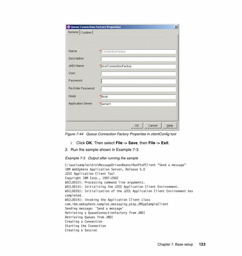
Figure 7-44 Queue Connection Factory Properties in clientConfig tool
i. Click OK. Then select File -> Save, then File -> Exit.
3. Run the sample shown in Example 7-3.
Example 7-3 Output after running the sample
C:\was\samples\bin\MessageDrivenBeans>RunPtoPClient "Send a message"IBM WebSphere Application Server, Release 5.0J2EE Application Client ToolCopyright IBM Corp., 1997-2002WSCL0012I: Processing command line arguments.WSCL0013I: Initializing the J2EE Application Client Environment.WSCL0035I: Initialization of the J2EE Application Client Environment has completed.WSCL0014I: Invoking the Application Client class com.ibm.websphere.samples.messaging.ptop.JMSppSampleClientSending message: 'Send a message'Retrieving a QueueConnectionFactory from JNDIRetrieving Queues from JNDICreating a ConnectionStarting the ConnectionCreating a Session
Chapter 7. Base setup 123
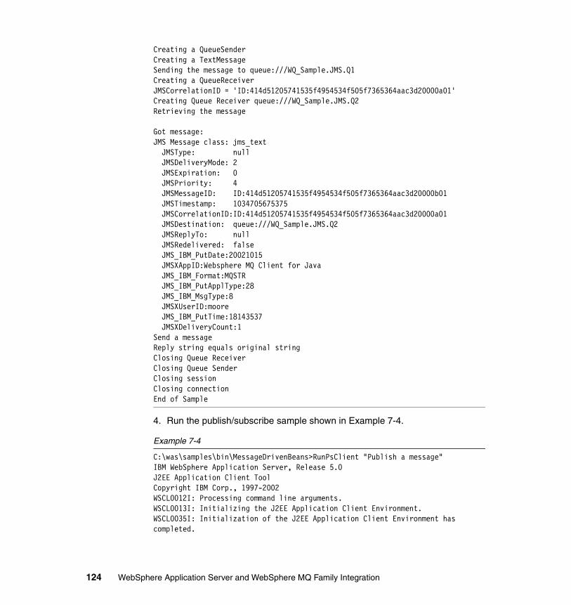
Creating a QueueSenderCreating a TextMessageSending the message to queue:///WQ_Sample.JMS.Q1Creating a QueueReceiverJMSCorrelationID = 'ID:414d51205741535f4954534f505f7365364aac3d20000a01'Creating Queue Receiver queue:///WQ_Sample.JMS.Q2Retrieving the message
Got message:JMS Message class: jms_text JMSType: null JMSDeliveryMode: 2 JMSExpiration: 0 JMSPriority: 4 JMSMessageID: ID:414d51205741535f4954534f505f7365364aac3d20000b01 JMSTimestamp: 1034705675375 JMSCorrelationID:ID:414d51205741535f4954534f505f7365364aac3d20000a01 JMSDestination: queue:///WQ_Sample.JMS.Q2 JMSReplyTo: null JMSRedelivered: false JMS_IBM_PutDate:20021015 JMSXAppID:Websphere MQ Client for Java JMS_IBM_Format:MQSTR JMS_IBM_PutApplType:28 JMS_IBM_MsgType:8 JMSXUserID:moore JMS_IBM_PutTime:18143537 JMSXDeliveryCount:1Send a messageReply string equals original stringClosing Queue ReceiverClosing Queue SenderClosing sessionClosing connectionEnd of Sample
4. Run the publish/subscribe sample shown in Example 7-4.
Example 7-4
C:\was\samples\bin\MessageDrivenBeans>RunPsClient "Publish a message"IBM WebSphere Application Server, Release 5.0J2EE Application Client ToolCopyright IBM Corp., 1997-2002WSCL0012I: Processing command line arguments.WSCL0013I: Initializing the J2EE Application Client Environment.WSCL0035I: Initialization of the J2EE Application Client Environment has completed.
124 WebSphere Application Server and WebSphere MQ Family Integration
WSCL0014I: Invoking the Application Client class com.ibm.websphere.samples.messaging.pubsub.JMSpsSampleClientSending message: 'Publish a message'Retrieving a TopicConnectionFactory from JNDIRetrieving Topic from JNDICreating a ConnectionStarting the ConnectionCreating a SessionCreating a TopicPublisherCreating a TextMessagePublish the message to topic://Sample/JMS/news?brokerVersion=1Closing PublisherClosing sessionClosing connectionEnd of Sample
7.7 Installing WebSphere Studio Application DeveloperThe steps to install WebSphere Studio Application Developer are:
1. Start the WebSphere Studio installation launcher and select Install WebSphere Studio Application Developer. Figure 7-45 on page 126 shows the launcher.
Chapter 7. Base setup 125
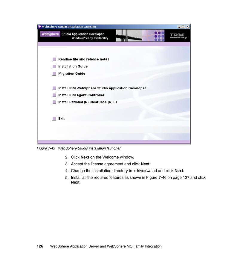
Figure 7-45 WebSphere Studio installation launcher
2. Click Next on the Welcome window.
3. Accept the license agreement and click Next.
4. Change the installation directory to <drive>\wsad and click Next.
5. Install all the required features as shown in Figure 7-46 on page 127 and click Next.
126 WebSphere Application Server and WebSphere MQ Family Integration
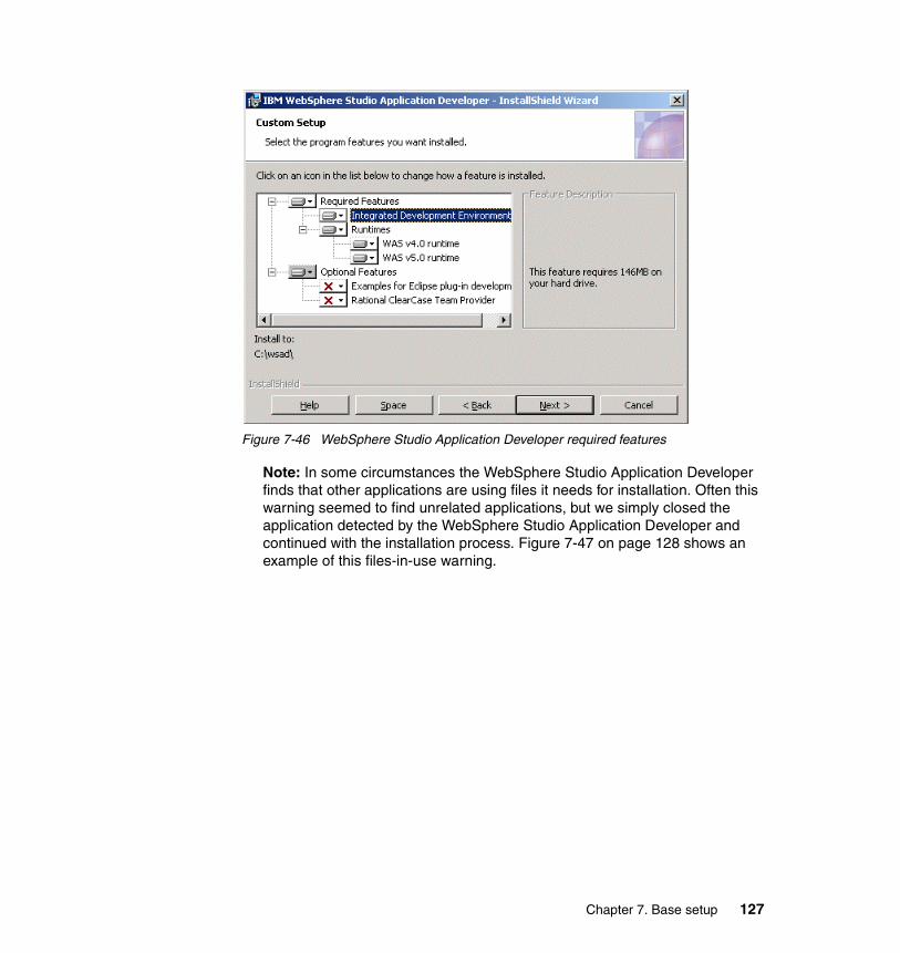
Figure 7-46 WebSphere Studio Application Developer required features
Note: In some circumstances the WebSphere Studio Application Developer finds that other applications are using files it needs for installation. Often this warning seemed to find unrelated applications, but we simply closed the application detected by the WebSphere Studio Application Developer and continued with the installation process. Figure 7-47 on page 128 shows an example of this files-in-use warning.
Chapter 7. Base setup 127
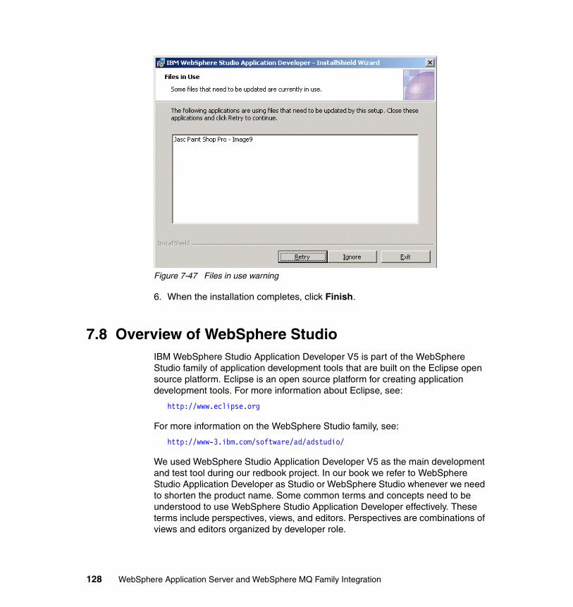
Figure 7-47 Files in use warning
6. When the installation completes, click Finish.
7.8 Overview of WebSphere StudioIBM WebSphere Studio Application Developer V5 is part of the WebSphere Studio family of application development tools that are built on the Eclipse open source platform. Eclipse is an open source platform for creating application development tools. For more information about Eclipse, see:
http://www.eclipse.org
For more information on the WebSphere Studio family, see:
http://www-3.ibm.com/software/ad/adstudio/
We used WebSphere Studio Application Developer V5 as the main development and test tool during our redbook project. In our book we refer to WebSphere Studio Application Developer as Studio or WebSphere Studio whenever we need to shorten the product name. Some common terms and concepts need to be understood to use WebSphere Studio Application Developer effectively. These terms include perspectives, views, and editors. Perspectives are combinations of views and editors organized by developer role.
128 WebSphere Application Server and WebSphere MQ Family Integration
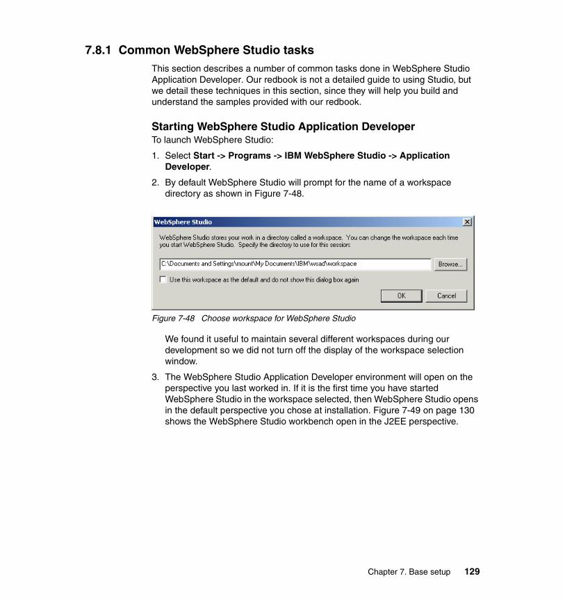
7.8.1 Common WebSphere Studio tasksThis section describes a number of common tasks done in WebSphere Studio Application Developer. Our redbook is not a detailed guide to using Studio, but we detail these techniques in this section, since they will help you build and understand the samples provided with our redbook.
Starting WebSphere Studio Application DeveloperTo launch WebSphere Studio:
1. Select Start -> Programs -> IBM WebSphere Studio -> Application Developer.
2. By default WebSphere Studio will prompt for the name of a workspace directory as shown in Figure 7-48.
Figure 7-48 Choose workspace for WebSphere Studio
We found it useful to maintain several different workspaces during our development so we did not turn off the display of the workspace selection window.
3. The WebSphere Studio Application Developer environment will open on the perspective you last worked in. If it is the first time you have started WebSphere Studio in the workspace selected, then WebSphere Studio opens in the default perspective you chose at installation. Figure 7-49 on page 130 shows the WebSphere Studio workbench open in the J2EE perspective.
Chapter 7. Base setup 129
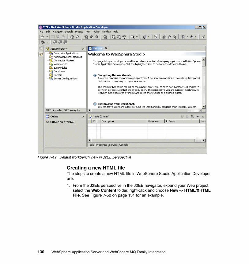
Figure 7-49 Default workbench view in J2EE perspective
Creating a new HTML fileThe steps to create a new HTML file in WebSphere Studio Application Developer are:
1. From the J2EE perspective in the J2EE navigator, expand your Web project, select the Web Content folder, right-click and choose New -> HTML/XHTML File. See Figure 7-50 on page 131 for an example.
130 WebSphere Application Server and WebSphere MQ Family Integration
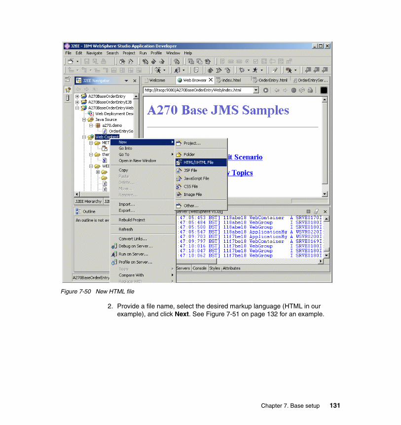
Figure 7-50 New HTML file
2. Provide a file name, select the desired markup language (HTML in our example), and click Next. See Figure 7-51 on page 132 for an example.
Chapter 7. Base setup 131
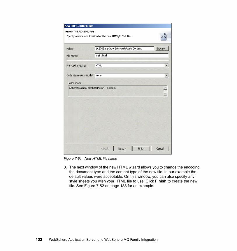
Figure 7-51 New HTML file name
3. The next window of the new HTML wizard allows you to change the encoding, the document type and the content type of the new file. In our example the default values were acceptable. On this window, you can also specify any style sheets you wish your HTML file to use. Click Finish to create the new file. See Figure 7-52 on page 133 for an example.
132 WebSphere Application Server and WebSphere MQ Family Integration
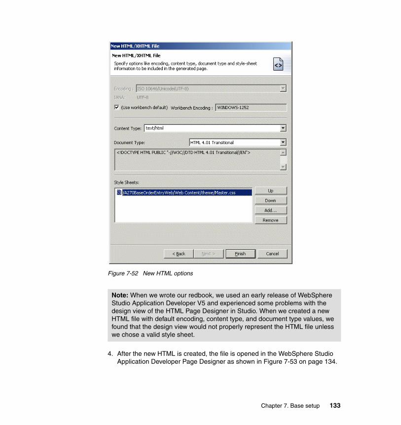
Figure 7-52 New HTML options
4. After the new HTML is created, the file is opened in the WebSphere Studio Application Developer Page Designer as shown in Figure 7-53 on page 134.
Note: When we wrote our redbook, we used an early release of WebSphere Studio Application Developer V5 and experienced some problems with the design view of the HTML Page Designer in Studio. When we created a new HTML file with default encoding, content type, and document type values, we found that the design view would not properly represent the HTML file unless we chose a valid style sheet.
Chapter 7. Base setup 133
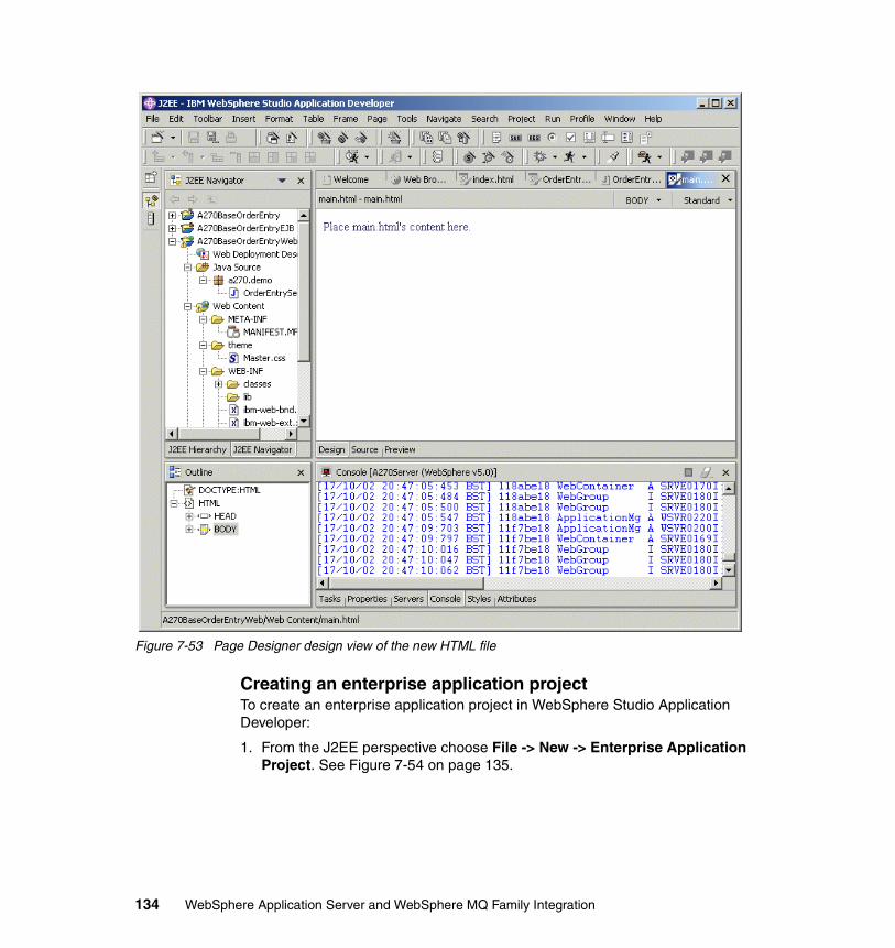
Figure 7-53 Page Designer design view of the new HTML file
Creating an enterprise application projectTo create an enterprise application project in WebSphere Studio Application Developer:
1. From the J2EE perspective choose File -> New -> Enterprise Application Project. See Figure 7-54 on page 135.
134 WebSphere Application Server and WebSphere MQ Family Integration
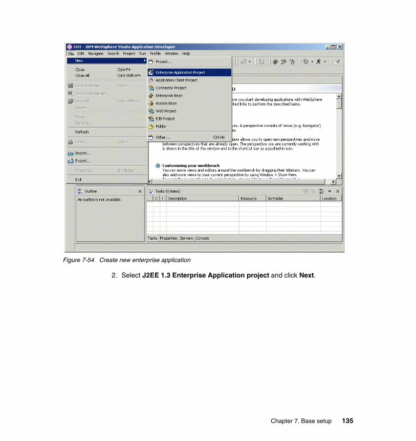
Figure 7-54 Create new enterprise application
2. Select J2EE 1.3 Enterprise Application project and click Next.
Chapter 7. Base setup 135
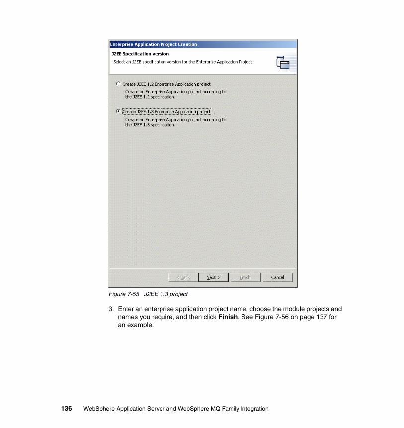
Figure 7-55 J2EE 1.3 project
3. Enter an enterprise application project name, choose the module projects and names you require, and then click Finish. See Figure 7-56 on page 137 for an example.
136 WebSphere Application Server and WebSphere MQ Family Integration
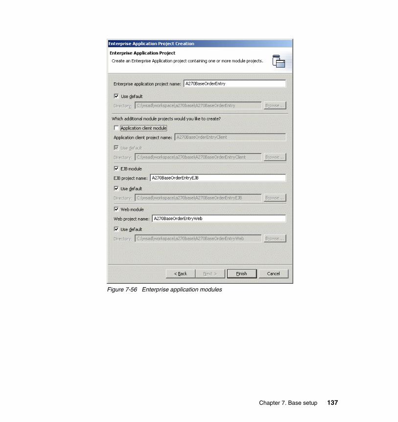
Figure 7-56 Enterprise application modules
Chapter 7. Base setup 137
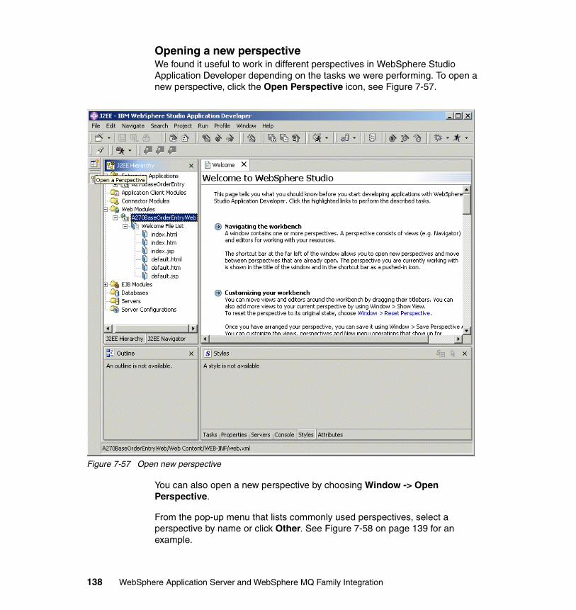
Opening a new perspectiveWe found it useful to work in different perspectives in WebSphere Studio Application Developer depending on the tasks we were performing. To open a new perspective, click the Open Perspective icon, see Figure 7-57.
Figure 7-57 Open new perspective
You can also open a new perspective by choosing Window -> Open Perspective.
From the pop-up menu that lists commonly used perspectives, select a perspective by name or click Other. See Figure 7-58 on page 139 for an example.
138 WebSphere Application Server and WebSphere MQ Family Integration
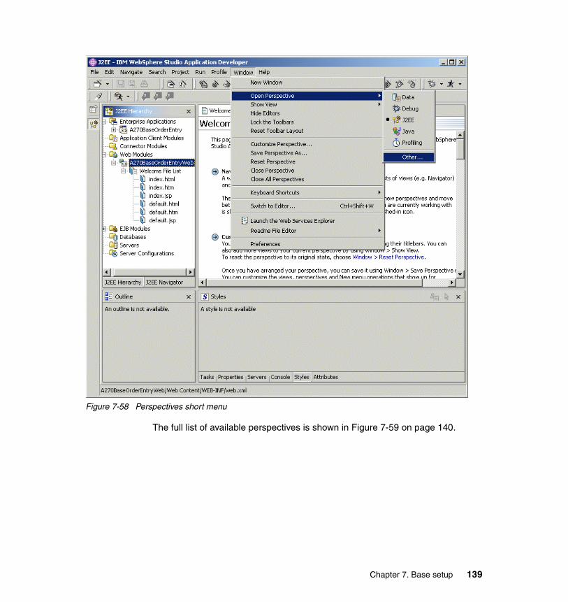
Figure 7-58 Perspectives short menu
The full list of available perspectives is shown in Figure 7-59 on page 140.
Chapter 7. Base setup 139
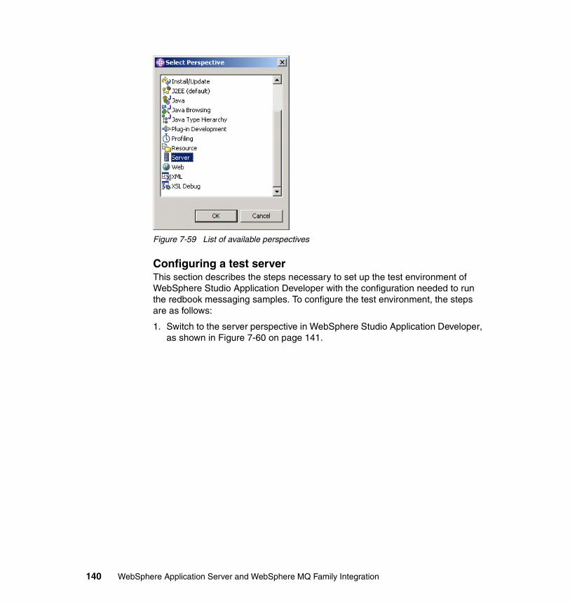
Figure 7-59 List of available perspectives
Configuring a test serverThis section describes the steps necessary to set up the test environment of WebSphere Studio Application Developer with the configuration needed to run the redbook messaging samples. To configure the test environment, the steps are as follows:
1. Switch to the server perspective in WebSphere Studio Application Developer, as shown in Figure 7-60 on page 141.
140 WebSphere Application Server and WebSphere MQ Family Integration
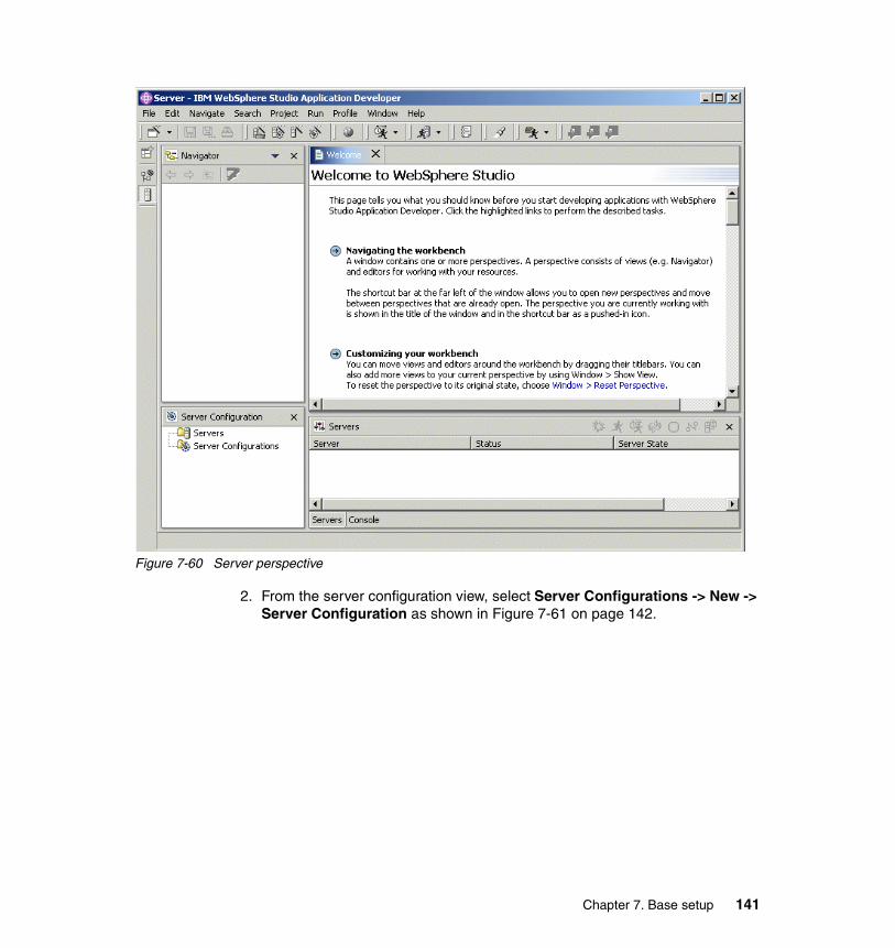
Figure 7-60 Server perspective
2. From the server configuration view, select Server Configurations -> New -> Server Configuration as shown in Figure 7-61 on page 142.
Chapter 7. Base setup 141
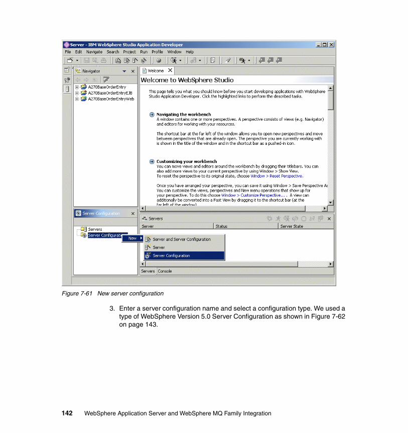
Figure 7-61 New server configuration
3. Enter a server configuration name and select a configuration type. We used a type of WebSphere Version 5.0 Server Configuration as shown in Figure 7-62 on page 143.
142 WebSphere Application Server and WebSphere MQ Family Integration
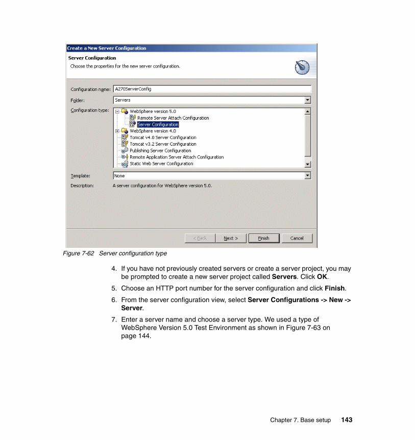
Figure 7-62 Server configuration type
4. If you have not previously created servers or create a server project, you may be prompted to create a new server project called Servers. Click OK.
5. Choose an HTTP port number for the server configuration and click Finish.
6. From the server configuration view, select Server Configurations -> New -> Server.
7. Enter a server name and choose a server type. We used a type of WebSphere Version 5.0 Test Environment as shown in Figure 7-63 on page 144.
Chapter 7. Base setup 143
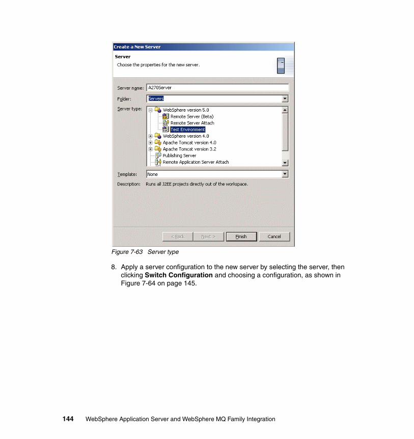
Figure 7-63 Server type
8. Apply a server configuration to the new server by selecting the server, then clicking Switch Configuration and choosing a configuration, as shown in Figure 7-64 on page 145.
144 WebSphere Application Server and WebSphere MQ Family Integration
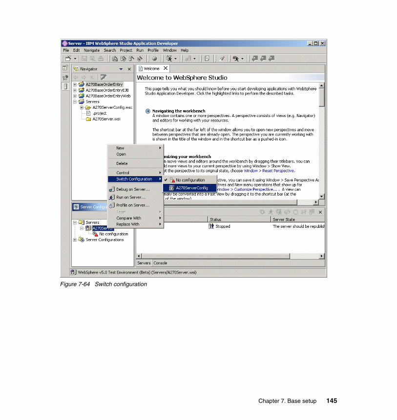
Figure 7-64 Switch configuration
Chapter 7. Base setup 145

146 WebSphere Application Server and WebSphere MQ Family Integration
Chapter 8. Embedded Messaging scenarios
This chapter describes those parts of an order entry application that implement the sample scenarios used to illustrate the base functionality of the Embedded Messaging function of WebSphere Application Server V5.
The following topics are presented in this chapter:
� The application architecture is presented. A high-level view of the components involved in the solution is given.
� A brief presentation of additional components that are used to verify the behavior of the application follows.
� The deployment of the application is explained.
� The use of the application in exercising the different scenarios is covered along with the procedures to verify the results.
� Code snippets from the application that illustrate the base functionality of the Embedded Messaging feature are discussed.
8
© Copyright IBM Corp. 2003. All rights reserved. 147
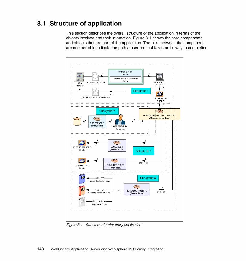
8.1 Structure of applicationThis section describes the overall structure of the application in terms of the objects involved and their interaction. Figure 8-1 shows the core components and objects that are part of the application. The links between the components are numbered to indicate the path a user request takes on its way to completion.
Figure 8-1 Structure of order entry application
148 WebSphere Application Server and WebSphere MQ Family Integration
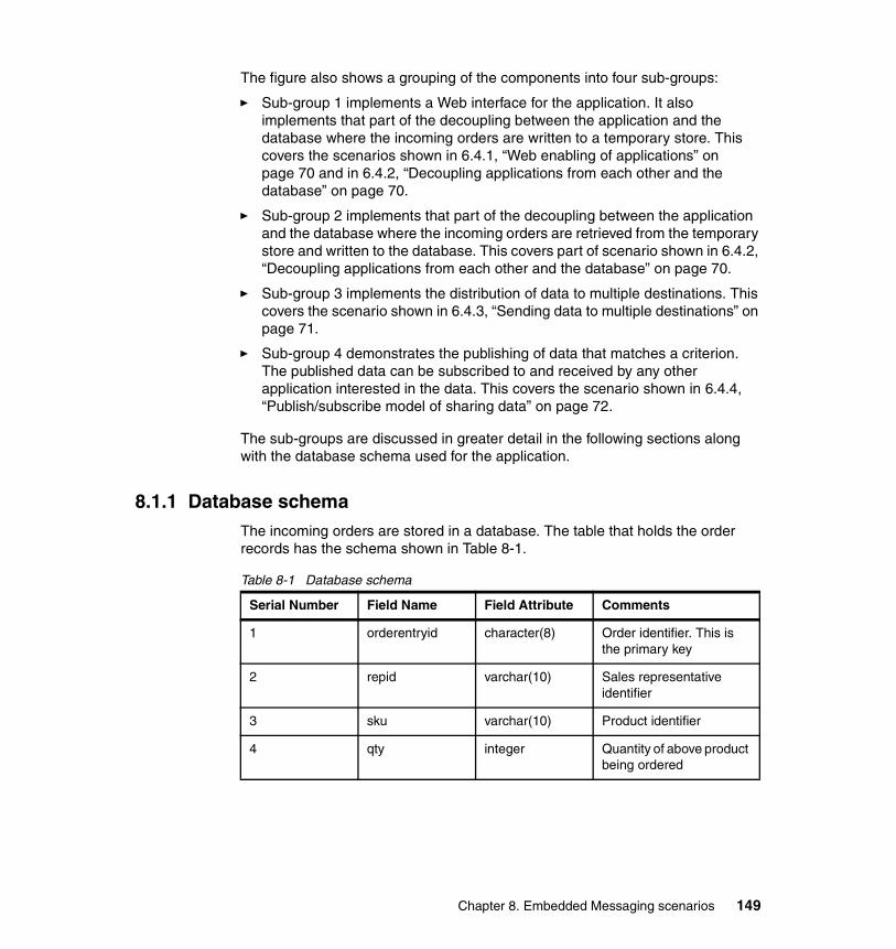
The figure also shows a grouping of the components into four sub-groups:
� Sub-group 1 implements a Web interface for the application. It also implements that part of the decoupling between the application and the database where the incoming orders are written to a temporary store. This covers the scenarios shown in 6.4.1, “Web enabling of applications” on page 70 and in 6.4.2, “Decoupling applications from each other and the database” on page 70.
� Sub-group 2 implements that part of the decoupling between the application and the database where the incoming orders are retrieved from the temporary store and written to the database. This covers part of scenario shown in 6.4.2, “Decoupling applications from each other and the database” on page 70.
� Sub-group 3 implements the distribution of data to multiple destinations. This covers the scenario shown in 6.4.3, “Sending data to multiple destinations” on page 71.
� Sub-group 4 demonstrates the publishing of data that matches a criterion. The published data can be subscribed to and received by any other application interested in the data. This covers the scenario shown in 6.4.4, “Publish/subscribe model of sharing data” on page 72.
The sub-groups are discussed in greater detail in the following sections along with the database schema used for the application.
8.1.1 Database schemaThe incoming orders are stored in a database. The table that holds the order records has the schema shown in Table 8-1.
Table 8-1 Database schema
Serial Number Field Name Field Attribute Comments
1 orderentryid character(8) Order identifier. This is the primary key
2 repid varchar(10) Sales representative identifier
3 sku varchar(10) Product identifier
4 qty integer Quantity of above product being ordered
Chapter 8. Embedded Messaging scenarios 149
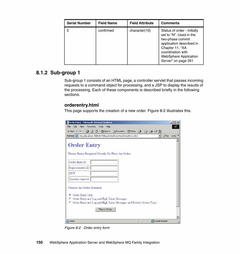
8.1.2 Sub-group 1Sub-group 1 consists of an HTML page, a controller servlet that passes incoming requests to a command object for processing, and a JSP to display the results of the processing. Each of these components is described briefly in the following sections.
orderentry.htmlThis page supports the creation of a new order. Figure 8-2 illustrates this.
Figure 8-2 Order entry form
5 confirmed character(10) Status of order - initially set to “N”. Used in the two-phase commit application described in Chapter 11, “XA coordination with WebSphere Application Server” on page 261
Serial Number Field Name Field Attribute Comments
150 WebSphere Application Server and WebSphere MQ Family Integration
The input fields reflect the first four fields of the schema described above. A SKU value beginning with “C” is considered a celebrity item, while a value beginning with “F” is considered a fashion item. A quantity greater than 99 is considered an order of high value.
The page has three radio buttons that allow tailoring of the application behavior:
� Order Entry Only
Triggers the components in sub-group 2 which then enter the order into the database. The confirmed field of the record is set to “N”.
� Order Entry and Log and High Value Messages
Triggers the components in both sub-groups 2 and 3. In addition to being entered in the database, the order is written to a log queue and if it is of a high value, it is also written to a high value queue.
� Order Entry and Log and High Value Messages and Publish Order Topics
The components in sub-groups 2, 3, and 4 are triggered. In addition to the actions for the preceding option, a high value order is published to one of three different topics, depending upon the product being ordered. All high value orders for fashion items are published to a Fashion Bestseller Topic. All high value orders for celebrity items are published to a Celebrity Bestseller Topic. High value orders for all other items are published to a High Value Topic.
OrderEntryServletThis is the controller servlet for the application. For each request it receives from a user, it performs the following steps:
1. Creates an instance of the OrderEntryCommandImpl class.
2. Validates and stores the request parameters in the OrderEntryCommandImpl object. This includes the option chosen on the orderentry.html form that identifies the scenarios or sub-groups to execute.
3. Creates an HTTP session for the request.
4. Invokes the execute method on the OrderEntryCommandImpl object that causes the execution of the chosen scenarios. The results of the processing are stored in the OrderEntryCommandImpl object.
5. Stores the OrderEntryCommandImpl object in the session and redirects the request to the OrderEntryAcknowledged JSP, which then displays the results of the processing to the user.
Chapter 8. Embedded Messaging scenarios 151
OrderEntryCommandImplThis is a Java helper class that is used by the OrderEntryServlet to process a request. It implements two interfaces: one to store and retrieve the attributes of an order and the other to process the order. The method we are primarily interested is the execute method. It does the following:
1. Instantiates an object of the OrderEntryProducer class
2. Using the OrderEntryProducer object, establishes communication with the JS provider
3. Using the OrderEntryProducer object, sends a message containing the order information to the OrderEntryQ queue
OrderEntryProducerThis is a Java helper class that is used by OrderEntryCommandImpl. There are two methods in this class that are of interest: prepareJMSSender and sendOrderEntry.
The prepareJMSSender method does the following:
1. Looks up the resource needed to communicate with the JMS provider.
2. Looks up the OrderEntryQ queue.
3. Establishes communication with the JMS provider.
The sendOrderEntry method does the following:
1. Starts a transaction.
2. Sends a message containing the order information as well as the selected option.
3. Commits the local transaction.
4. Terminates the communication established with the JMS provider.
OrderEntryAcknowledged JSPThe JSP uses the OrderEntryCommandImpl object passed to it as part of the session to retrieve information on the order just entered. From this information, it creates an HTML page to be sent back as a result of processing the request.
8.1.3 Sub-group 2Sub-group 2 consists of a message-driven bean that is triggered by an incoming message containing an order and a helper class that persists the order to the database using an entity bean. Each of these components is described in more detail in the following sections.
152 WebSphere Application Server and WebSphere MQ Family Integration
OrderEntryMessageReceiverThis is a message-driven bean that retrieves orders from the OrderEntryQ and stores them in the database. Its onMessage() method performs the following steps:
1. Retrieves the option selected by the user from the incoming message.
2. The message obtained from OrderEntryQ is converted to an instance of an OrderEntryMessage type. The purpose of this conversion is to store both the headers and the body of the message. The header information is used when logging the message. The body contains information pertaining to the order.
3. Calls its saveOrderEntry method, which does the following:
a. Instantiates an instance of the OrderEntryConsumer helper class.
b. Passes the order portion of the incoming message to the saveOrderEntry method of this helper class. This persists the order to the database.
4. If option 2 was selected, it does the following:
a. Looks up and creates an instance of the LogSender session bean. Passes the OrderEntryMessage object to this bean for writing to the LogOrderEntryQ.
b. If the order is of high value, looks up and creates an instance of the HighValueSender session bean. This bean is given the order information to write to the HighValueQ.
5. If option 3 was selected, it does the following:
a. Performs all the steps listed above for option 2.
b. In addition, if the order is of high value, looks up and creates an instance of the HighValuePublisher session bean. This bean is given the order information to publish to the appropriate topics.
OrderEntryConsumerThis is a helper class used by the OrderEntryMessageReceiver bean described above. It has a single method named saveOrderEntry, which is passed the order information and performs the following steps:
� Looks up and creates the OrderEntry entity bean. The key used is the Order Entry ID field.
� Sets the various fields of the entity bean with data from the order information.
OrderEntryThis is the entity bean that represents order records in the database.
Chapter 8. Embedded Messaging scenarios 153
8.1.4 Sub-group 3Sub-group 3 consists of the OrderEntryMessageReceiver message-driven bean that was discussed in “OrderEntryMessageReceiver” on page 153, a session bean that writes a log message to a log queue, and another session bean that writes the order to a high value queue if the order is of high value. The role of OrderEntryMessageReceiver has been completely discussed in the preceding section and is not discussed further here. The other components are described in greater detail in the following sections.
LogSenderThis is a session bean that writes a log message containing both the header from the original message as well as the order information to the LogOrderEntryQ. It has a single method called sendOrderEntryLog, which is given an instance of OrderEntryMessage as input. This method does the following:
1. Looks up the resource needed to establish communication with the JMS provider.
2. Establishes communication with the JMS provider.
3. Looks up the LogOrderEntryQ queue.
4. Starts a transaction.
5. Sends the log message to LogOrderEntryQ.
6. Commits the transaction.
7. Terminates the communication established to the JMS provider.
HighValueSenderThis is a session bean that writes a message containing order information to the HighValueQ. It has a single method named sendHighValueOrder that performs the following steps:
1. Looks up the resource needed to establish communication with the JMS provider.
2. Establishes communication with the JMS provider.
3. Looks up the HighValueQ queue.
4. Starts a transaction.
5. Sends the order message to HighValueQ.
6. Commits the transaction.
7. Terminates the communication established to the JMS provider.
154 WebSphere Application Server and WebSphere MQ Family Integration
8.1.5 Sub-group 4Sub-group 4 consists of the OrderEntryMessageReceiver message-driven bean and a session bean that publishes orders of high value to one of three topics. The role of the OrderEntryMessageReceiver message-driven bean has been completely discussed in “OrderEntryMessageReceiver” on page 153and is not discussed further here. The other component is described in greater detail in the following sections.
HighValuePublisherThis is a session bean that publishes an order to one of three topics depending on the value of the SKU field in the order. It has a single method named publishHighValueOrder that is passed the order information and performs the following steps:
1. Looks up the resource needed to establish communications with the JMS provider.
2. Establishes communication with the JMS provider.
3. Starts a transaction.
4. If the SKU for the order starts with the character “F”, it looks up the topic named HighValueFashionTopic.
5. If the SKU for the order starts with the character “C”, it looks up the topic named HighValueCelebrityTopic.
6. Otherwise, it looks up the topic named HighValueTopic.
7. Publishes the order to the topic that was looked up.
8. Commits the publish.
9. Terminates the communication established with the JMS provider.
8.2 Application verificationIn addition to the core application components discussed in the previous section, other components were developed that enable users to check that the application works as expected.
When an order has been successfully processed, the results should be as follows:
� A new order record should be seen in the database.
� A new message consisting of the order and the header from the original message should be seen in LogOrderEntryQ.
Chapter 8. Embedded Messaging scenarios 155
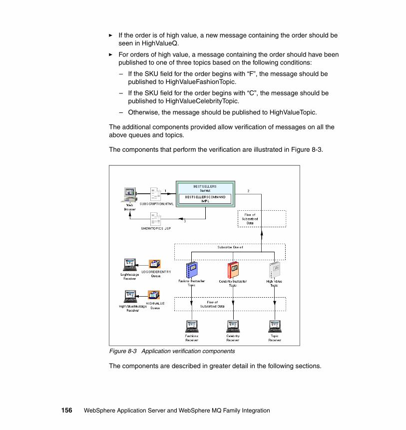
� If the order is of high value, a new message containing the order should be seen in HighValueQ.
� For orders of high value, a message containing the order should have been published to one of three topics based on the following conditions:
– If the SKU field for the order begins with “F”, the message should be published to HighValueFashionTopic.
– If the SKU field for the order begins with “C”, the message should be published to HighValueCelebrityTopic.
– Otherwise, the message should be published to HighValueTopic.
The additional components provided allow verification of messages on all the above queues and topics.
The components that perform the verification are illustrated in Figure 8-3.
Figure 8-3 Application verification components
The components are described in greater detail in the following sections.
156 WebSphere Application Server and WebSphere MQ Family Integration
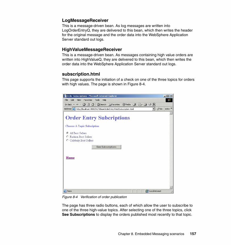
LogMessageReceiverThis is a message-driven bean. As log messages are written into LogOrderEntryQ, they are delivered to this bean, which then writes the header for the original message and the order data into the WebSphere Application Server standard out logs.
HighValueMessageReceiverThis is a message-driven bean. As messages containing high value orders are written into HighValueQ, they are delivered to this bean, which then writes the order data into the WebSphere Application Server standard out logs.
subscription.htmlThis page supports the initiation of a check on one of the three topics for orders with high values. The page is shown in Figure 8-4.
Figure 8-4 Verification of order publication
The page has three radio buttons, each of which allow the user to subscribe to one of the three high-value topics. After selecting one of the three topics, click See Subscriptions to display the orders published most recently to that topic.
Chapter 8. Embedded Messaging scenarios 157
BestSellersServletThis is the controller servlet that processes requests to check for new publications to the chosen topic. For each request it receives from a user, it performs the following steps:
� Creates an instance of the BestSellersCommandImpl class.
� Validates and stores the request parameter containing the selected topic in the BestSellersCommandImpl object.
� Creates an HTTP session for the request.
� Invokes the execute method on the BestSellersCommandImpl object that causes the check on a chosen topic to be made. The results of the check are stored in the BestSellersCommandImpl object.
� Stores the BestSellersCommandImpl object in the session and redirects the request to the ShowTopics JSP, which then displays the results of the processing to the user.
BestSellersCommandImplThis is a Java helper class that is used by the BestSellersServlet to perform a check on the topic selected by the user. The main method in the class is subscribe(), which performs the following steps:
1. Looks up the resource used to establish communications with the JMS provider.
2. Establishes communication with the JMS provider.
3. Looks up a durable subscription to the topic.
4. Starts delivery of messages that are subscribed to.
5. Polls a few times for any messages and gathersany received messages.
6. Terminates the communications with the JMS provider.
ShowTopics JSPThis JSP uses the BestSellersCommandImpl object passed to it as part of the session to build an HTML page. The generated page shows the results of the check made on the topic chosen by the user. The JSP returns the generated page in response to the request.
This completes the discussion on the components that allow verification of the application behavior.
158 WebSphere Application Server and WebSphere MQ Family Integration
8.3 Deployment of order entry applicationInstructions on obtaining the order entry application and deploying it on base WebSphere Application Server V5 are given in this section. Where extra details for any particular step are needed with regard to a procedure in base WebSphere Application Server V5, a reference to the appropriate set of instructions listed elsewhere in the book is given.
8.3.1 Instructions to download applicationThe application can be downloaded as detailed in Appendix E, “Additional material” on page 435. The file A270BaseOrderEntry.ear can be installed in a suitable directory on the target machine. For the purpose of this discussion, assume that the file is stored in c:\temp\orderentry.
8.3.2 Setting up the database tablesThe order entry application uses a database to persist orders. It is assumed that DB2 is up and running. This section discusses the creation of the tables.
The downloaded file is an archive containing another file named Table.ddl that can be used to create the needed tables in the database. To extract the file and create the necessary tables, run the following in a DOS window:
cd c:\temp\orderentryjar xvf A270BaseOrderEntry.earjar xvf A270BaseOrderEntryEJB.jar META-INF/Table.ddl
Next, run the following in a DB2 command window:
db2 create database TZFORUdb2 connect to TZFORU user <your-windows-id> using <your-windows-password>cd c:\temp\orderentry\META-INFdb2 -tf Table.ddl
This creates the database tables needed to run the order entry application.
8.3.3 Connecting WebSphere Application Server to the databaseA data source needs to be created for the TZFORU database. However, there are several steps that need to be performed both prior to and after creating the data source. All the steps involved are described in the following sections in the order they need to be performed.
Chapter 8. Embedded Messaging scenarios 159
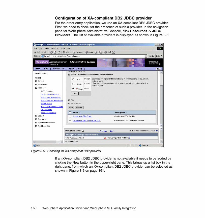
Configuration of XA-compliant DB2 JDBC providerFor the order entry application, we use an XA-compliant DB2 JDBC provider. First, we need to check for the presence of such a provider. In the navigation pane for WebSphere Administrative Console, click Resources -> JDBC Providers. The list of available providers is displayed as shown in Figure 8-5.
Figure 8-5 Checking for XA-compliant DB2 provider
If an XA-compliant DB2 JDBC provider is not available it needs to be added by clicking the New button in the upper-right pane. This brings up a list box in the right pane, from which an XA-compliant DB2 JDBC provider can be selected as shown in Figure 8-6 on page 161.
160 WebSphere Application Server and WebSphere MQ Family Integration
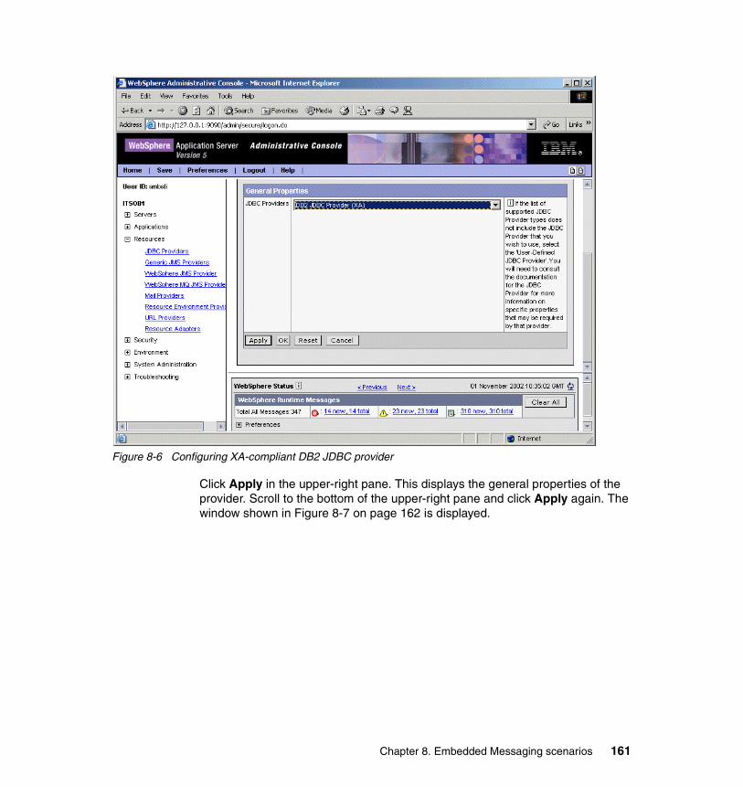
Figure 8-6 Configuring XA-compliant DB2 JDBC provider
Click Apply in the upper-right pane. This displays the general properties of the provider. Scroll to the bottom of the upper-right pane and click Apply again. The window shown in Figure 8-7 on page 162 is displayed.
Chapter 8. Embedded Messaging scenarios 161
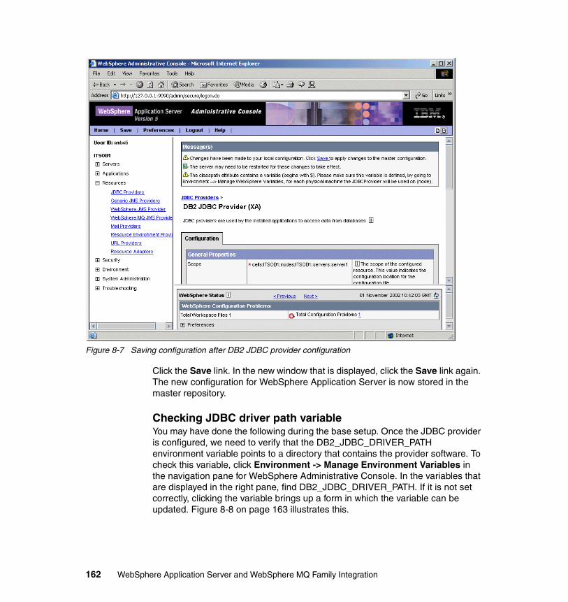
Figure 8-7 Saving configuration after DB2 JDBC provider configuration
Click the Save link. In the new window that is displayed, click the Save link again. The new configuration for WebSphere Application Server is now stored in the master repository.
Checking JDBC driver path variableYou may have done the following during the base setup. Once the JDBC provider is configured, we need to verify that the DB2_JDBC_DRIVER_PATH environment variable points to a directory that contains the provider software. To check this variable, click Environment -> Manage Environment Variables in the navigation pane for WebSphere Administrative Console. In the variables that are displayed in the right pane, find DB2_JDBC_DRIVER_PATH. If it is not set correctly, clicking the variable brings up a form in which the variable can be updated. Figure 8-8 on page 163 illustrates this.
162 WebSphere Application Server and WebSphere MQ Family Integration
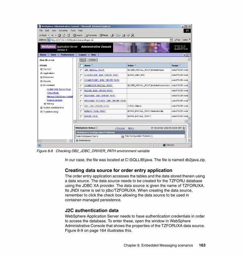
Figure 8-8 Checking DB2_JDBC_DRIVER_PATH environment variable
In our case, the file was located at C:\SQLLIB\java. The file is named db2java.zip.
Creating data source for order entry applicationThe order entry application accesses the tables and the data stored therein using a data source. The data source needs to be created for the TZFORU database using the JDBC XA provider. The data source is given the name of TZFORUXA. Its JNDI name is set to jdbc/TZFORUXA. When creating the data source, remember to click the check box allowing the data source to be used in container-managed persistence.
J2C authentication dataWebSphere Application Server needs to have authentication credentials in order to access the database. To enter these, open the window in WebSphere Administrative Console that shows the properties of the TZFORUXA data source. Figure 8-9 on page 164 illustrates this.
Chapter 8. Embedded Messaging scenarios 163
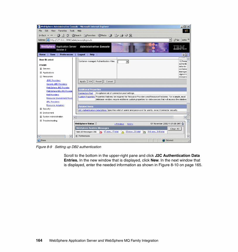
Figure 8-9 Setting up DB2 authentication
Scroll to the bottom in the upper-right pane and click J2C Authentication Data Entries. In the new window that is displayed, click New. In the next window that is displayed, enter the needed information as shown in Figure 8-10 on page 165.
164 WebSphere Application Server and WebSphere MQ Family Integration
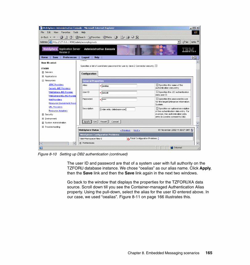
Figure 8-10 Setting up DB2 authentication (continued)
The user ID and password are that of a system user with full authority on the TZFORU database instance. We chose “oealias” as our alias name. Click Apply, then the Save link and then the Save link again in the next two windows.
Go back to the window that displays the properties for the TZFORUXA data source. Scroll down till you see the Container-managed Authentication Alias property. Using the pull-down, select the alias for the user ID entered above. In our case, we used “oealias”. Figure 8-11 on page 166 illustrates this.
Chapter 8. Embedded Messaging scenarios 165
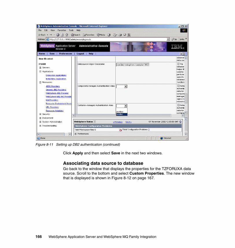
Figure 8-11 Setting up DB2 authentication (continued)
Click Apply and then select Save in the next two windows.
Associating data source to databaseGo back to the window that displays the properties for the TZFORUXA data source. Scroll to the bottom and select Custom Properties. The new window that is displayed is shown in Figure 8-12 on page 167.
166 WebSphere Application Server and WebSphere MQ Family Integration
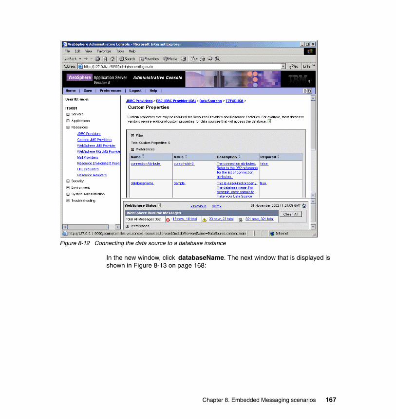
Figure 8-12 Connecting the data source to a database instance
In the new window, click databaseName. The next window that is displayed is shown in Figure 8-13 on page 168:
Chapter 8. Embedded Messaging scenarios 167
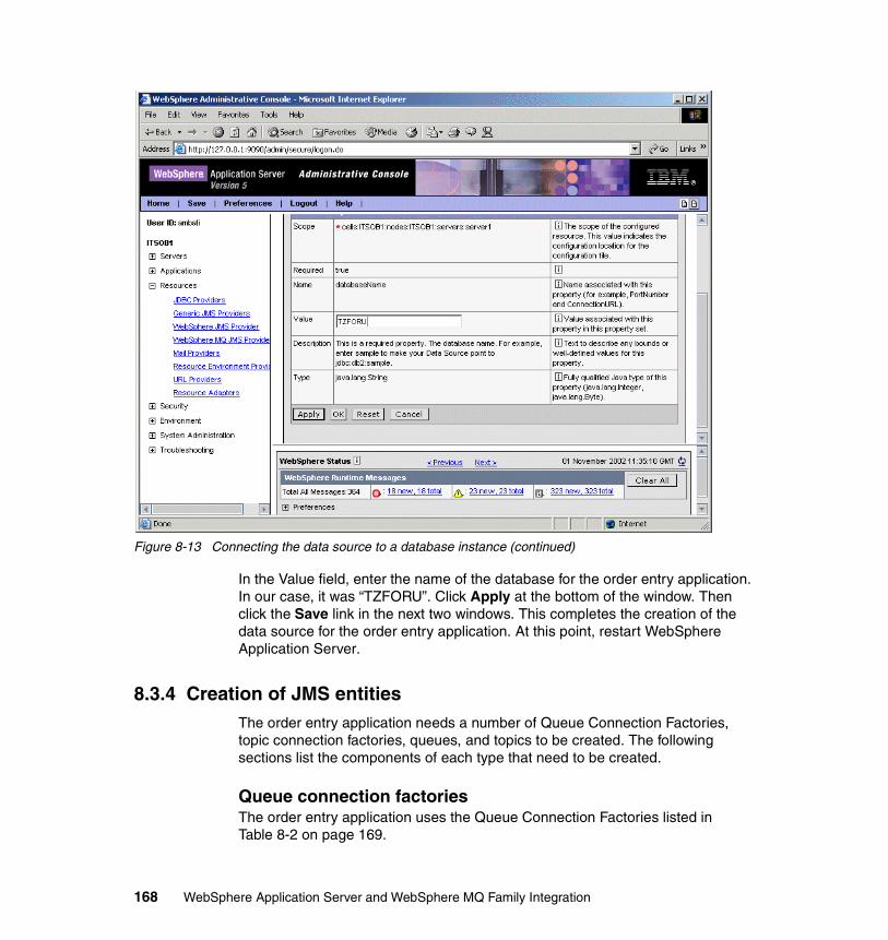
Figure 8-13 Connecting the data source to a database instance (continued)
In the Value field, enter the name of the database for the order entry application. In our case, it was “TZFORU”. Click Apply at the bottom of the window. Then click the Save link in the next two windows. This completes the creation of the data source for the order entry application. At this point, restart WebSphere Application Server.
8.3.4 Creation of JMS entitiesThe order entry application needs a number of Queue Connection Factories, topic connection factories, queues, and topics to be created. The following sections list the components of each type that need to be created.
Queue connection factoriesThe order entry application uses the Queue Connection Factories listed in Table 8-2 on page 169.
168 WebSphere Application Server and WebSphere MQ Family Integration
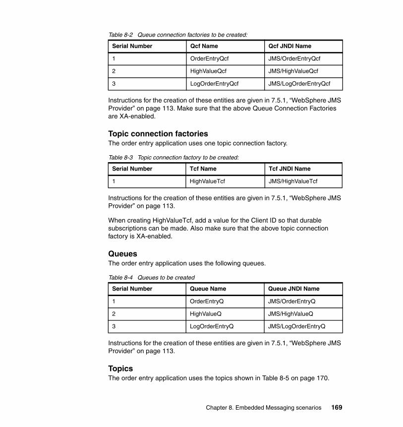
Table 8-2 Queue connection factories to be created:
Instructions for the creation of these entities are given in 7.5.1, “WebSphere JMS Provider” on page 113. Make sure that the above Queue Connection Factories are XA-enabled.
Topic connection factoriesThe order entry application uses one topic connection factory.
Table 8-3 Topic connection factory to be created:
Instructions for the creation of these entities are given in 7.5.1, “WebSphere JMS Provider” on page 113.
When creating HighValueTcf, add a value for the Client ID so that durable subscriptions can be made. Also make sure that the above topic connection factory is XA-enabled.
QueuesThe order entry application uses the following queues.
Table 8-4 Queues to be created
Instructions for the creation of these entities are given in 7.5.1, “WebSphere JMS Provider” on page 113.
TopicsThe order entry application uses the topics shown in Table 8-5 on page 170.
Serial Number Qcf Name Qcf JNDI Name
1 OrderEntryQcf JMS/OrderEntryQcf
2 HighValueQcf JMS/HighValueQcf
3 LogOrderEntryQcf JMS/LogOrderEntryQcf
Serial Number Tcf Name Tcf JNDI Name
1 HighValueTcf JMS/HighValueTcf
Serial Number Queue Name Queue JNDI Name
1 OrderEntryQ JMS/OrderEntryQ
2 HighValueQ JMS/HighValueQ
3 LogOrderEntryQ JMS/LogOrderEntryQ
Chapter 8. Embedded Messaging scenarios 169
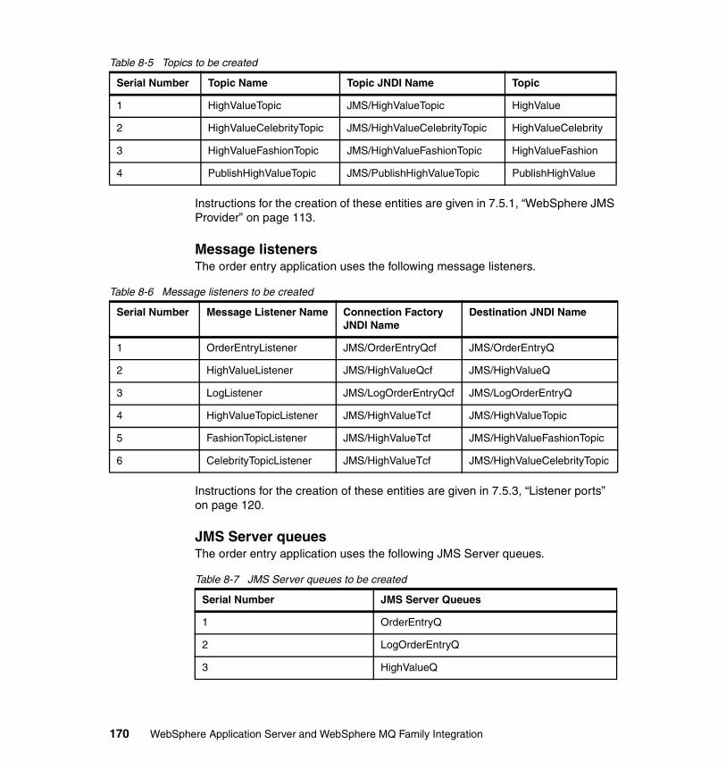
Table 8-5 Topics to be created
Instructions for the creation of these entities are given in 7.5.1, “WebSphere JMS Provider” on page 113.
Message listenersThe order entry application uses the following message listeners.
Table 8-6 Message listeners to be created
Instructions for the creation of these entities are given in 7.5.3, “Listener ports” on page 120.
JMS Server queuesThe order entry application uses the following JMS Server queues.
Table 8-7 JMS Server queues to be created
Serial Number Topic Name Topic JNDI Name Topic
1 HighValueTopic JMS/HighValueTopic HighValue
2 HighValueCelebrityTopic JMS/HighValueCelebrityTopic HighValueCelebrity
3 HighValueFashionTopic JMS/HighValueFashionTopic HighValueFashion
4 PublishHighValueTopic JMS/PublishHighValueTopic PublishHighValue
Serial Number Message Listener Name Connection Factory JNDI Name
Destination JNDI Name
1 OrderEntryListener JMS/OrderEntryQcf JMS/OrderEntryQ
2 HighValueListener JMS/HighValueQcf JMS/HighValueQ
3 LogListener JMS/LogOrderEntryQcf JMS/LogOrderEntryQ
4 HighValueTopicListener JMS/HighValueTcf JMS/HighValueTopic
5 FashionTopicListener JMS/HighValueTcf JMS/HighValueFashionTopic
6 CelebrityTopicListener JMS/HighValueTcf JMS/HighValueCelebrityTopic
Serial Number JMS Server Queues
1 OrderEntryQ
2 LogOrderEntryQ
3 HighValueQ
170 WebSphere Application Server and WebSphere MQ Family Integration
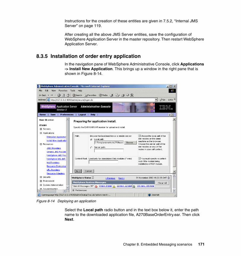
Instructions for the creation of these entities are given in 7.5.2, “Internal JMS Server” on page 119.
After creating all the above JMS Server entities, save the configuration of WebSphere Application Server in the master repository. Then restart WebSphere Application Server.
8.3.5 Installation of order entry applicationIn the navigation pane of WebSphere Administrative Console, click Applications -> Install New Application. This brings up a window in the right pane that is shown in Figure 8-14.
Figure 8-14 Deploying an application
Select the Local path radio button and in the text box below it, enter the path name to the downloaded application file, A270BaseOrderEntry.ear. Then click Next.
Chapter 8. Embedded Messaging scenarios 171
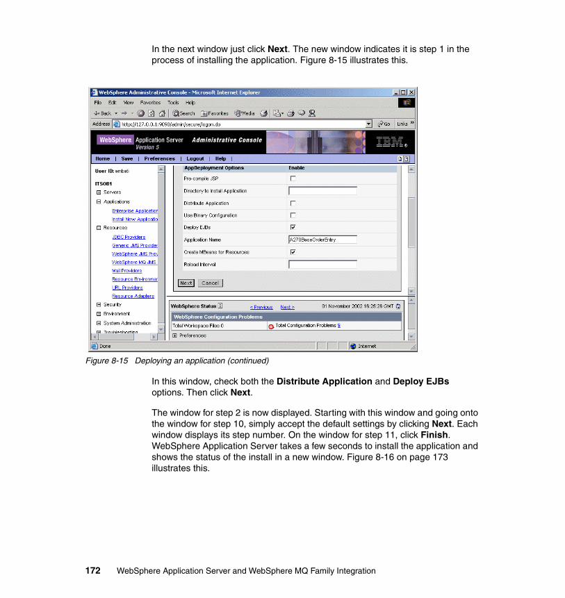
In the next window just click Next. The new window indicates it is step 1 in the process of installing the application. Figure 8-15 illustrates this.
Figure 8-15 Deploying an application (continued)
In this window, check both the Distribute Application and Deploy EJBs options. Then click Next.
The window for step 2 is now displayed. Starting with this window and going onto the window for step 10, simply accept the default settings by clicking Next. Each window displays its step number. On the window for step 11, click Finish. WebSphere Application Server takes a few seconds to install the application and shows the status of the install in a new window. Figure 8-16 on page 173 illustrates this.
172 WebSphere Application Server and WebSphere MQ Family Integration
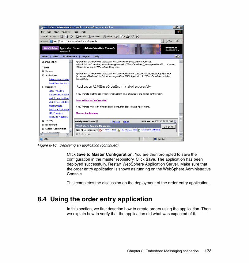
Figure 8-16 Deploying an application (continued)
Click Save to Master Configuration. You are then prompted to save the configuration in the master repository. Click Save. The application has been deployed successfully. Restart WebSphere Application Server. Make sure that the order entry application is shown as running on the WebSphere Administrative Console.
This completes the discussion on the deployment of the order entry application.
8.4 Using the order entry applicationIn this section, we first describe how to create orders using the application. Then we explain how to verify that the application did what was expected of it.
Chapter 8. Embedded Messaging scenarios 173
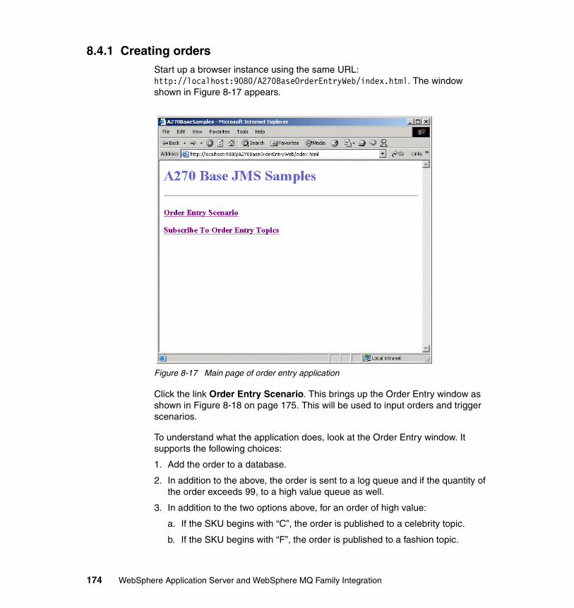
8.4.1 Creating ordersStart up a browser instance using the same URL: http://localhost:9080/A270BaseOrderEntryWeb/index.html. The window shown in Figure 8-17 appears.
Figure 8-17 Main page of order entry application
Click the link Order Entry Scenario. This brings up the Order Entry window as shown in Figure 8-18 on page 175. This will be used to input orders and trigger scenarios.
To understand what the application does, look at the Order Entry window. It supports the following choices:
1. Add the order to a database.
2. In addition to the above, the order is sent to a log queue and if the quantity of the order exceeds 99, to a high value queue as well.
3. In addition to the two options above, for an order of high value:
a. If the SKU begins with “C”, the order is published to a celebrity topic.
b. If the SKU begins with “F”, the order is published to a fashion topic.
174 WebSphere Application Server and WebSphere MQ Family Integration
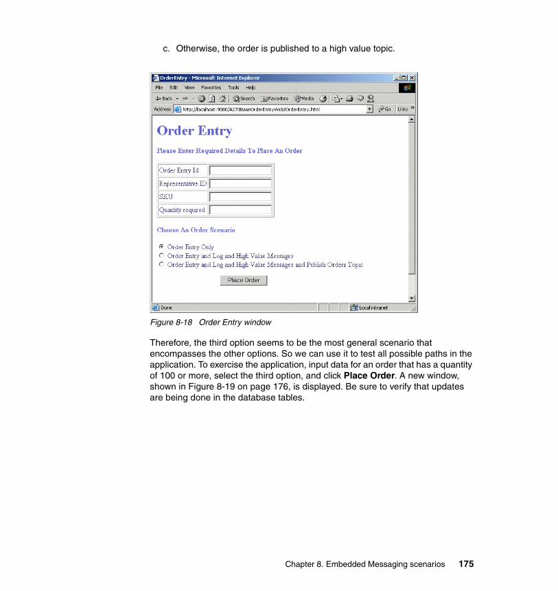
c. Otherwise, the order is published to a high value topic.
Figure 8-18 Order Entry window
Therefore, the third option seems to be the most general scenario that encompasses the other options. So we can use it to test all possible paths in the application. To exercise the application, input data for an order that has a quantity of 100 or more, select the third option, and click Place Order. A new window, shown in Figure 8-19 on page 176, is displayed. Be sure to verify that updates are being done in the database tables.
Chapter 8. Embedded Messaging scenarios 175
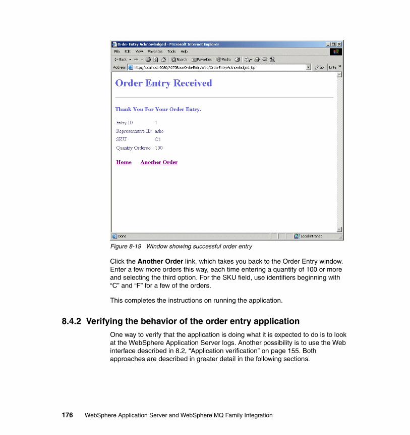
Figure 8-19 Window showing successful order entry
Click the Another Order link. which takes you back to the Order Entry window. Enter a few more orders this way, each time entering a quantity of 100 or more and selecting the third option. For the SKU field, use identifiers beginning with “C” and “F” for a few of the orders.
This completes the instructions on running the application.
8.4.2 Verifying the behavior of the order entry applicationOne way to verify that the application is doing what it is expected to do is to look at the WebSphere Application Server logs. Another possibility is to use the Web interface described in 8.2, “Application verification” on page 155. Both approaches are described in greater detail in the following sections.
176 WebSphere Application Server and WebSphere MQ Family Integration
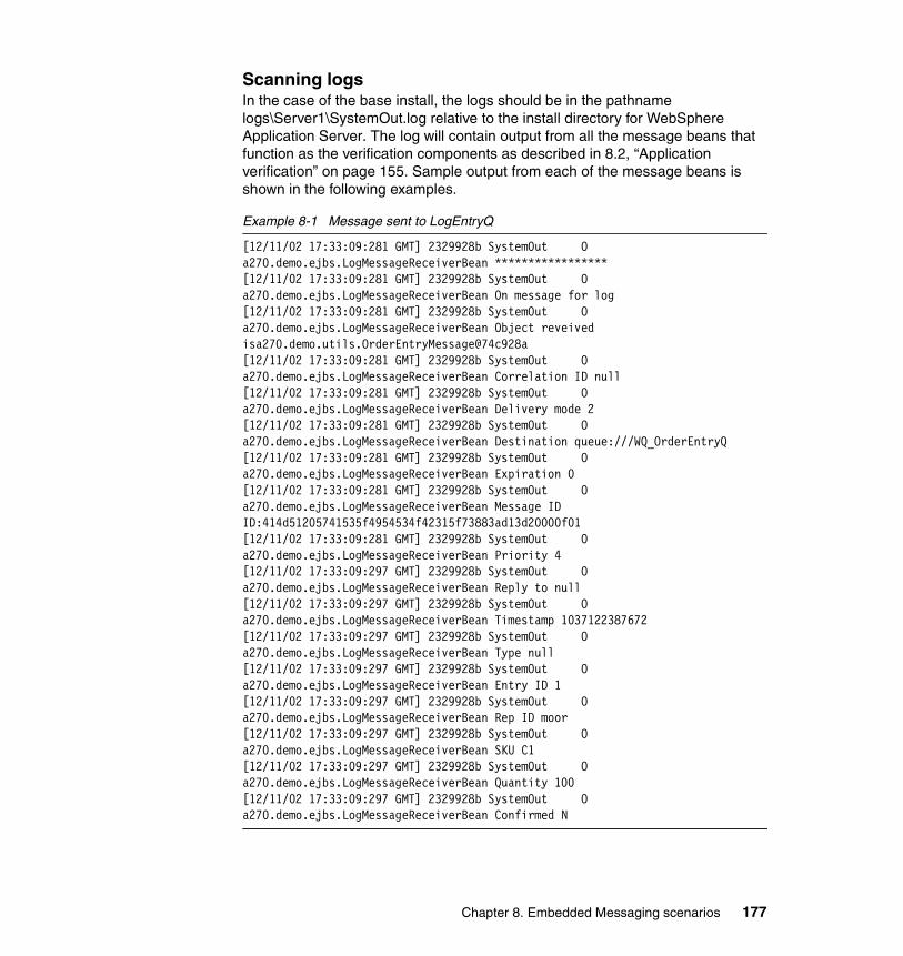
Scanning logsIn the case of the base install, the logs should be in the pathname logs\Server1\SystemOut.log relative to the install directory for WebSphere Application Server. The log will contain output from all the message beans that function as the verification components as described in 8.2, “Application verification” on page 155. Sample output from each of the message beans is shown in the following examples.
Example 8-1 Message sent to LogEntryQ
[12/11/02 17:33:09:281 GMT] 2329928b SystemOut O a270.demo.ejbs.LogMessageReceiverBean ***************** [12/11/02 17:33:09:281 GMT] 2329928b SystemOut O a270.demo.ejbs.LogMessageReceiverBean On message for log[12/11/02 17:33:09:281 GMT] 2329928b SystemOut O a270.demo.ejbs.LogMessageReceiverBean Object reveived isa270.demo.utils.OrderEntryMessage@74c928a[12/11/02 17:33:09:281 GMT] 2329928b SystemOut O a270.demo.ejbs.LogMessageReceiverBean Correlation ID null[12/11/02 17:33:09:281 GMT] 2329928b SystemOut O a270.demo.ejbs.LogMessageReceiverBean Delivery mode 2[12/11/02 17:33:09:281 GMT] 2329928b SystemOut O a270.demo.ejbs.LogMessageReceiverBean Destination queue:///WQ_OrderEntryQ[12/11/02 17:33:09:281 GMT] 2329928b SystemOut O a270.demo.ejbs.LogMessageReceiverBean Expiration 0[12/11/02 17:33:09:281 GMT] 2329928b SystemOut O a270.demo.ejbs.LogMessageReceiverBean Message ID ID:414d51205741535f4954534f42315f73883ad13d20000f01[12/11/02 17:33:09:281 GMT] 2329928b SystemOut O a270.demo.ejbs.LogMessageReceiverBean Priority 4[12/11/02 17:33:09:297 GMT] 2329928b SystemOut O a270.demo.ejbs.LogMessageReceiverBean Reply to null[12/11/02 17:33:09:297 GMT] 2329928b SystemOut O a270.demo.ejbs.LogMessageReceiverBean Timestamp 1037122387672[12/11/02 17:33:09:297 GMT] 2329928b SystemOut O a270.demo.ejbs.LogMessageReceiverBean Type null[12/11/02 17:33:09:297 GMT] 2329928b SystemOut O a270.demo.ejbs.LogMessageReceiverBean Entry ID 1[12/11/02 17:33:09:297 GMT] 2329928b SystemOut O a270.demo.ejbs.LogMessageReceiverBean Rep ID moor[12/11/02 17:33:09:297 GMT] 2329928b SystemOut O a270.demo.ejbs.LogMessageReceiverBean SKU C1[12/11/02 17:33:09:297 GMT] 2329928b SystemOut O a270.demo.ejbs.LogMessageReceiverBean Quantity 100[12/11/02 17:33:09:297 GMT] 2329928b SystemOut O a270.demo.ejbs.LogMessageReceiverBean Confirmed N
Chapter 8. Embedded Messaging scenarios 177
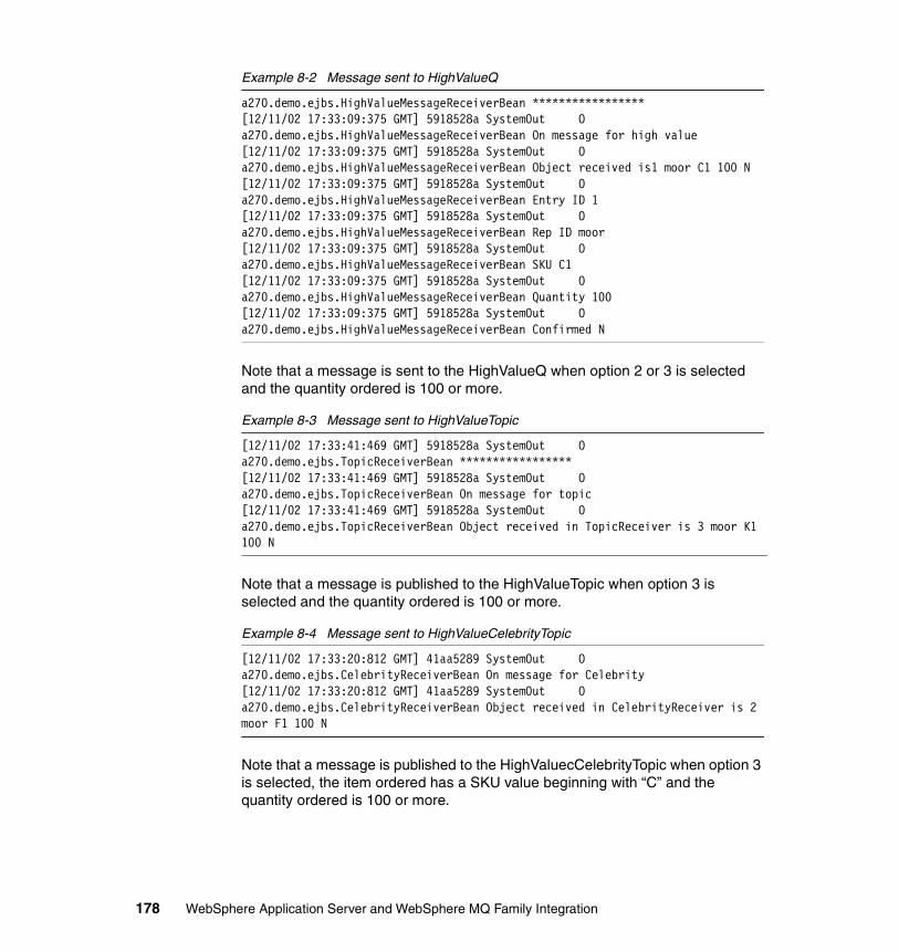
Example 8-2 Message sent to HighValueQ
a270.demo.ejbs.HighValueMessageReceiverBean ***************** [12/11/02 17:33:09:375 GMT] 5918528a SystemOut O a270.demo.ejbs.HighValueMessageReceiverBean On message for high value[12/11/02 17:33:09:375 GMT] 5918528a SystemOut O a270.demo.ejbs.HighValueMessageReceiverBean Object received is1 moor C1 100 N[12/11/02 17:33:09:375 GMT] 5918528a SystemOut O a270.demo.ejbs.HighValueMessageReceiverBean Entry ID 1[12/11/02 17:33:09:375 GMT] 5918528a SystemOut O a270.demo.ejbs.HighValueMessageReceiverBean Rep ID moor[12/11/02 17:33:09:375 GMT] 5918528a SystemOut O a270.demo.ejbs.HighValueMessageReceiverBean SKU C1[12/11/02 17:33:09:375 GMT] 5918528a SystemOut O a270.demo.ejbs.HighValueMessageReceiverBean Quantity 100[12/11/02 17:33:09:375 GMT] 5918528a SystemOut O a270.demo.ejbs.HighValueMessageReceiverBean Confirmed N
Note that a message is sent to the HighValueQ when option 2 or 3 is selected and the quantity ordered is 100 or more.
Example 8-3 Message sent to HighValueTopic
[12/11/02 17:33:41:469 GMT] 5918528a SystemOut O a270.demo.ejbs.TopicReceiverBean ***************** [12/11/02 17:33:41:469 GMT] 5918528a SystemOut O a270.demo.ejbs.TopicReceiverBean On message for topic[12/11/02 17:33:41:469 GMT] 5918528a SystemOut O a270.demo.ejbs.TopicReceiverBean Object received in TopicReceiver is 3 moor K1 100 N
Note that a message is published to the HighValueTopic when option 3 is selected and the quantity ordered is 100 or more.
Example 8-4 Message sent to HighValueCelebrityTopic
[12/11/02 17:33:20:812 GMT] 41aa5289 SystemOut O a270.demo.ejbs.CelebrityReceiverBean On message for Celebrity[12/11/02 17:33:20:812 GMT] 41aa5289 SystemOut O a270.demo.ejbs.CelebrityReceiverBean Object received in CelebrityReceiver is 2 moor F1 100 N
Note that a message is published to the HighValuecCelebrityTopic when option 3 is selected, the item ordered has a SKU value beginning with “C” and the quantity ordered is 100 or more.
178 WebSphere Application Server and WebSphere MQ Family Integration
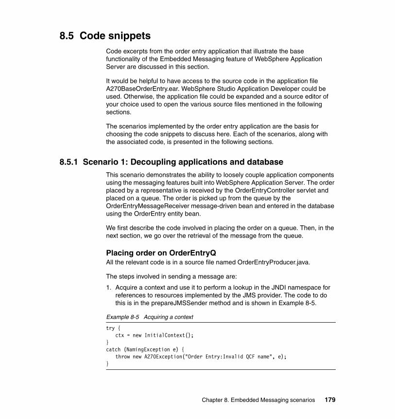
8.5 Code snippetsCode excerpts from the order entry application that illustrate the base functionality of the Embedded Messaging feature of WebSphere Application Server are discussed in this section.
It would be helpful to have access to the source code in the application file A270BaseOrderEntry.ear. WebSphere Studio Application Developer could be used. Otherwise, the application file could be expanded and a source editor of your choice used to open the various source files mentioned in the following sections.
The scenarios implemented by the order entry application are the basis for choosing the code snippets to discuss here. Each of the scenarios, along with the associated code, is presented in the following sections.
8.5.1 Scenario 1: Decoupling applications and databaseThis scenario demonstrates the ability to loosely couple application components using the messaging features built into WebSphere Application Server. The order placed by a representative is received by the OrderEntryController servlet and placed on a queue. The order is picked up from the queue by the OrderEntryMessageReceiver message-driven bean and entered in the database using the OrderEntry entity bean.
We first describe the code involved in placing the order on a queue. Then, in the next section, we go over the retrieval of the message from the queue.
Placing order on OrderEntryQAll the relevant code is in a source file named OrderEntryProducer.java.
The steps involved in sending a message are:
1. Acquire a context and use it to perform a lookup in the JNDI namespace for references to resources implemented by the JMS provider. The code to do this is in the prepareJMSSender method and is shown in Example 8-5.
Example 8-5 Acquiring a context
try {ctx = new InitialContext();
}catch (NamingException e) {
throw new A270Exception("Order Entry:Invalid QCF name", e);}
Chapter 8. Embedded Messaging scenarios 179
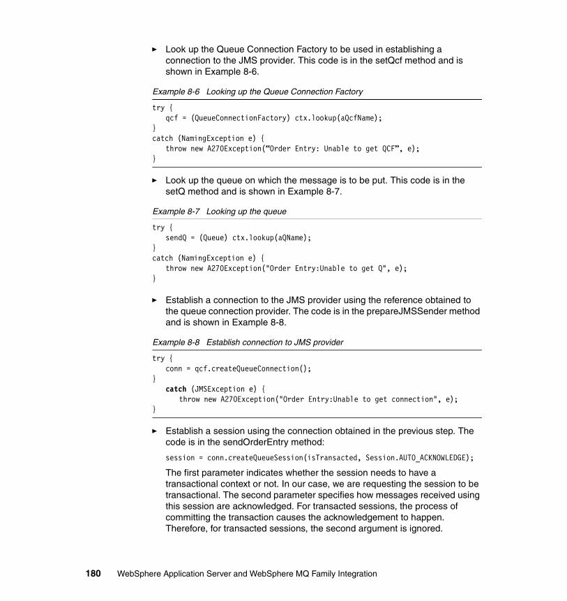
� Look up the Queue Connection Factory to be used in establishing a connection to the JMS provider. This code is in the setQcf method and is shown in Example 8-6.
Example 8-6 Looking up the Queue Connection Factory
try {qcf = (QueueConnectionFactory) ctx.lookup(aQcfName);
}catch (NamingException e) {
throw new A270Exception(“Order Entry: Unable to get QCF”, e);}
� Look up the queue on which the message is to be put. This code is in the setQ method and is shown in Example 8-7.
Example 8-7 Looking up the queue
try {sendQ = (Queue) ctx.lookup(aQName);
}catch (NamingException e) {
throw new A270Exception("Order Entry:Unable to get Q", e);}
� Establish a connection to the JMS provider using the reference obtained to the queue connection provider. The code is in the prepareJMSSender method and is shown in Example 8-8.
Example 8-8 Establish connection to JMS provider
try {conn = qcf.createQueueConnection();
}catch (JMSException e) {
throw new A270Exception("Order Entry:Unable to get connection", e);}
� Establish a session using the connection obtained in the previous step. The code is in the sendOrderEntry method:
session = conn.createQueueSession(isTransacted, Session.AUTO_ACKNOWLEDGE);
The first parameter indicates whether the session needs to have a transactional context or not. In our case, we are requesting the session to be transactional. The second parameter specifies how messages received using this session are acknowledged. For transacted sessions, the process of committing the transaction causes the acknowledgement to happen. Therefore, for transacted sessions, the second argument is ignored.
180 WebSphere Application Server and WebSphere MQ Family Integration
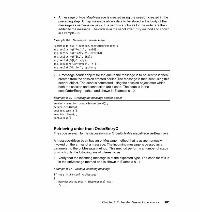
� A message of type MapMessage is created using the session created in the preceding step. A map message allows data to be stored in the body of the message as name-value pairs. The various attributes for the order are then added to the message. The code is in the sendOrderEntry method and shown in Example 8-9.
Example 8-9 Defining a map message
MapMessage msg = session.createMapMessage();msg.setString("RepId", repId);msg.setString("EntryId", entryId);msg.setString("SKU", SKU);msg.setInt("Qty", qty);msg.setChar("Confirmed", 'N');msg.setInt("Option", option);
� A message sender object for the queue the message is to be sent to is then created from the session created earlier. The message is then sent using this sender object. The send is committed using the session object after which both the session and connection are closed. The code is in the sendOrderEntry method and shown in Example 8-10.
Example 8-10 Creating the message sender object
sender = session.createSender(sendQ);sender.send(msg);session.commit();session.close();conn.close();
Retrieving order from OrderEntryQThe code relevant to this discussion is in OrderEntryMessageReceiverBean.java.
A message-driven bean has an onMessage method that is asynchronously invoked on the arrival of a message. The incoming message is passed as a parameter to the onMessage method. This method performs a number of steps of which only the following are of interest to us:
� Verify that the incoming message is of the expected type. The code for this is in the onMessage method and is shown in Example 8-11.
Example 8-11 Validate incoming message
if (msg instanceof MapMessage){
MapMessage mapMsg = (MapMessage) msg;// ...
Chapter 8. Embedded Messaging scenarios 181
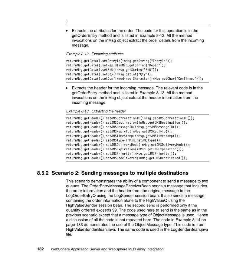
}
� Extracts the attributes for the order. The code for this operation is in the getOrderEntry method and is listed in Example 8-12. All the method invocations on the inMsg object extract the order details from the incoming message.
Example 8-12 Extracting attributes
returnMsg.getData().setEntryId(inMsg.getString("EntryId"));returnMsg.getData().setRepId(inMsg.getString("RepId"));returnMsg.getData().setSKU(inMsg.getString("SKU"));returnMsg.getData().setQty(inMsg.getInt("Qty"));returnMsg.getData().setConfirmed(new Character(inMsg.getChar("Confirmed")));
� Extracts the header for the incoming message. The relevant code is in the getOrderEntry method and is listed in Example 8-13. All the method invocations on the inMsg object extract the header information from the incoming message.
Example 8-13 Extracting the header
returnMsg.getHeader().setJMSCorrelationID(inMsg.getJMSCorrelationID());returnMsg.getHeader().setJMSDestination(inMsg.getJMSDestination());returnMsg.getHeader().setJMSMessageID(inMsg.getJMSMessageID());returnMsg.getHeader().setJMSReplyTo(inMsg.getJMSReplyTo());returnMsg.getHeader().setJMSTimestamp(inMsg.getJMSTimestamp());returnMsg.getHeader().setJMSType(inMsg.getJMSType());returnMsg.getHeader().setJMSDeliveryMode(inMsg.getJMSDeliveryMode());returnMsg.getHeader().setJMSExpiration(inMsg.getJMSExpiration());returnMsg.getHeader().setJMSPriority(inMsg.getJMSPriority());returnMsg.getHeader().setJMSRedelivered(inMsg.getJMSRedelivered());
8.5.2 Scenario 2: Sending messages to multiple destinationsThis scenario demonstrates the ability of a component to send a message to two queues. The OrderEntryMessageReceiverBean sends a message that includes the order information and the header from the original message to the LogOrderEntryQ using the LogSender session bean. It also sends a message containing the order information alone to the HighValueQ using the HighValueSender session bean. The second send is performed only if the quantity ordered exceeds 99. The code used here to send is the same as in the previous scenario except that a message type of ObjectMessage is used. Hence a discussion of all the code is not repeated here. The code in Example 8-14 on page 183 demonstrates the use of the ObjectMessage type. This code is from HighValueSenderBean.java. The same code is used in the LogSenderBean.java file.
182 WebSphere Application Server and WebSphere MQ Family Integration
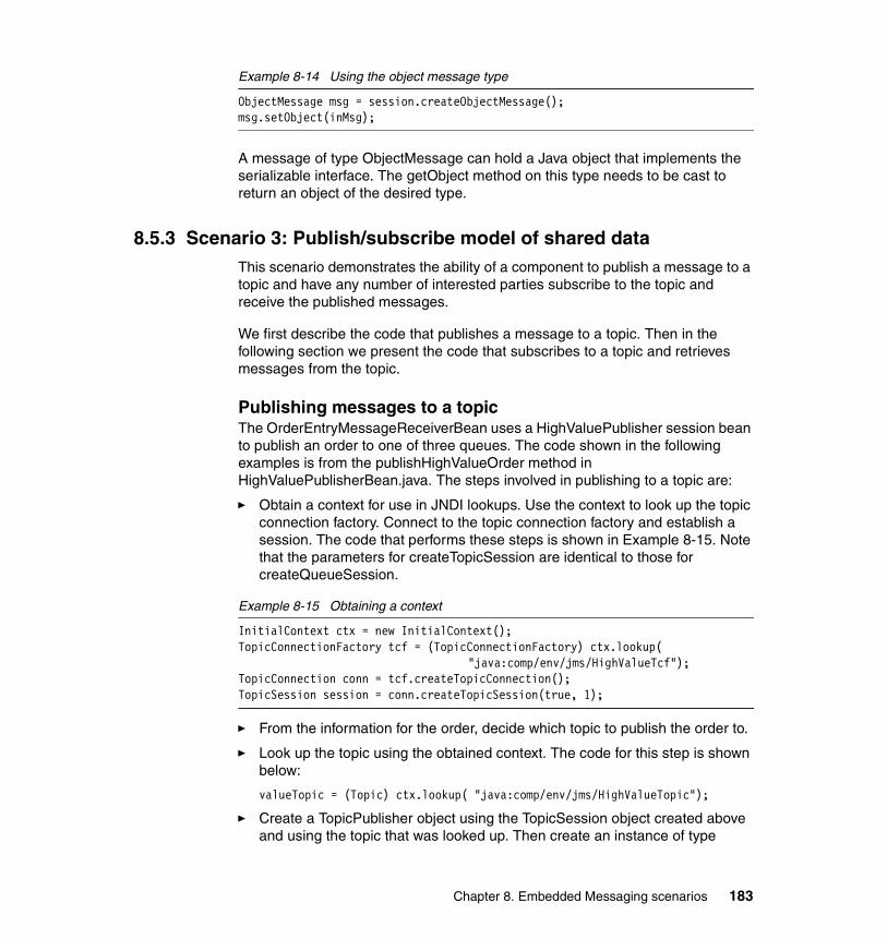
Example 8-14 Using the object message type
ObjectMessage msg = session.createObjectMessage();msg.setObject(inMsg);
A message of type ObjectMessage can hold a Java object that implements the serializable interface. The getObject method on this type needs to be cast to return an object of the desired type.
8.5.3 Scenario 3: Publish/subscribe model of shared dataThis scenario demonstrates the ability of a component to publish a message to a topic and have any number of interested parties subscribe to the topic and receive the published messages.
We first describe the code that publishes a message to a topic. Then in the following section we present the code that subscribes to a topic and retrieves messages from the topic.
Publishing messages to a topicThe OrderEntryMessageReceiverBean uses a HighValuePublisher session bean to publish an order to one of three queues. The code shown in the following examples is from the publishHighValueOrder method in HighValuePublisherBean.java. The steps involved in publishing to a topic are:
� Obtain a context for use in JNDI lookups. Use the context to look up the topic connection factory. Connect to the topic connection factory and establish a session. The code that performs these steps is shown in Example 8-15. Note that the parameters for createTopicSession are identical to those for createQueueSession.
Example 8-15 Obtaining a context
InitialContext ctx = new InitialContext();TopicConnectionFactory tcf = (TopicConnectionFactory) ctx.lookup(
"java:comp/env/jms/HighValueTcf");TopicConnection conn = tcf.createTopicConnection();TopicSession session = conn.createTopicSession(true, 1);
� From the information for the order, decide which topic to publish the order to.
� Look up the topic using the obtained context. The code for this step is shown below:
valueTopic = (Topic) ctx.lookup( "java:comp/env/jms/HighValueTopic");
� Create a TopicPublisher object using the TopicSession object created above and using the topic that was looked up. Then create an instance of type
Chapter 8. Embedded Messaging scenarios 183
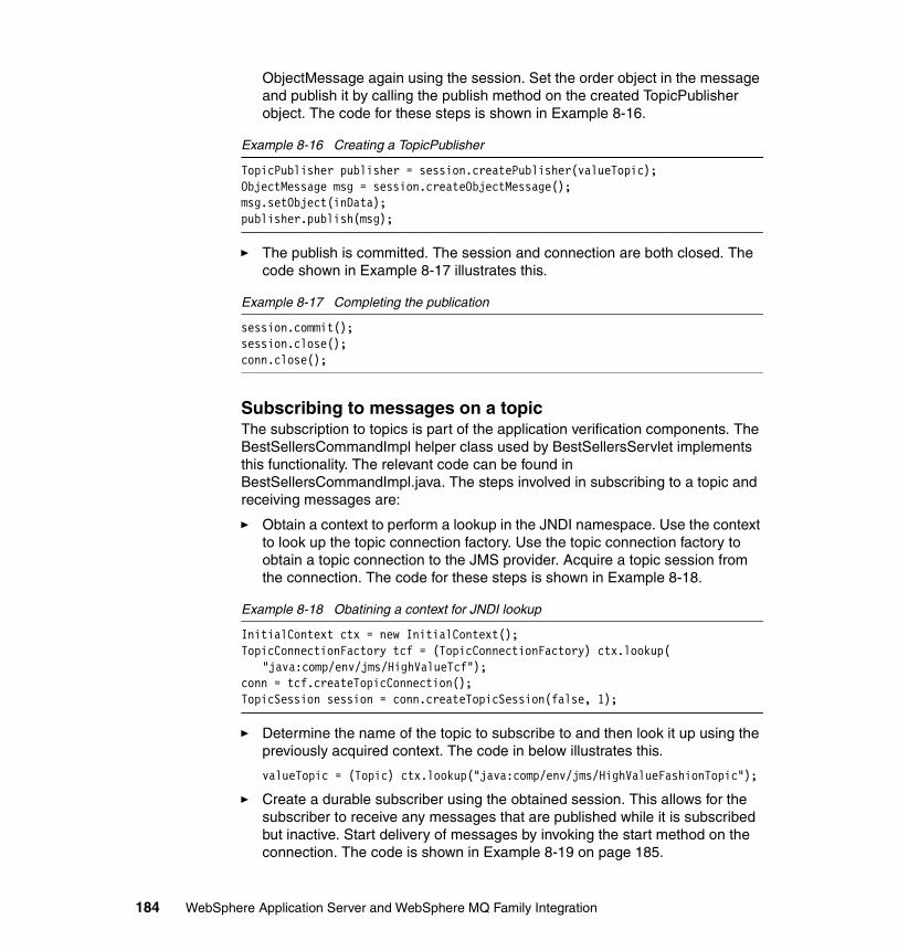
ObjectMessage again using the session. Set the order object in the message and publish it by calling the publish method on the created TopicPublisher object. The code for these steps is shown in Example 8-16.
Example 8-16 Creating a TopicPublisher
TopicPublisher publisher = session.createPublisher(valueTopic);ObjectMessage msg = session.createObjectMessage();msg.setObject(inData);publisher.publish(msg);
� The publish is committed. The session and connection are both closed. The code shown in Example 8-17 illustrates this.
Example 8-17 Completing the publication
session.commit();session.close();conn.close();
Subscribing to messages on a topicThe subscription to topics is part of the application verification components. The BestSellersCommandImpl helper class used by BestSellersServlet implements this functionality. The relevant code can be found in BestSellersCommandImpl.java. The steps involved in subscribing to a topic and receiving messages are:
� Obtain a context to perform a lookup in the JNDI namespace. Use the context to look up the topic connection factory. Use the topic connection factory to obtain a topic connection to the JMS provider. Acquire a topic session from the connection. The code for these steps is shown in Example 8-18.
Example 8-18 Obatining a context for JNDI lookup
InitialContext ctx = new InitialContext();TopicConnectionFactory tcf = (TopicConnectionFactory) ctx.lookup(
"java:comp/env/jms/HighValueTcf");conn = tcf.createTopicConnection();TopicSession session = conn.createTopicSession(false, 1);
� Determine the name of the topic to subscribe to and then look it up using the previously acquired context. The code in below illustrates this.
valueTopic = (Topic) ctx.lookup("java:comp/env/jms/HighValueFashionTopic");
� Create a durable subscriber using the obtained session. This allows for the subscriber to receive any messages that are published while it is subscribed but inactive. Start delivery of messages by invoking the start method on the connection. The code is shown in Example 8-19 on page 185.
184 WebSphere Application Server and WebSphere MQ Family Integration
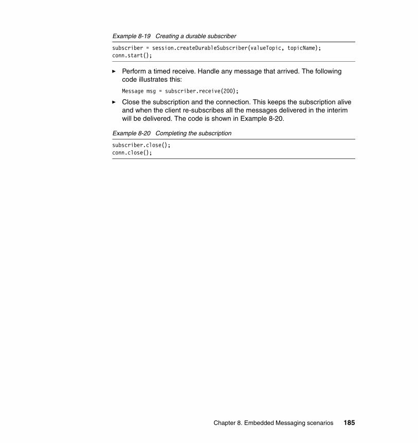
Example 8-19 Creating a durable subscriber
subscriber = session.createDurableSubscriber(valueTopic, topicName);conn.start();
� Perform a timed receive. Handle any message that arrived. The following code illustrates this:
Message msg = subscriber.receive(200);
� Close the subscription and the connection. This keeps the subscription alive and when the client re-subscribes all the messages delivered in the interim will be delivered. The code is shown in Example 8-20.
Example 8-20 Completing the subscription
subscriber.close();conn.close();
Chapter 8. Embedded Messaging scenarios 185

186 WebSphere Application Server and WebSphere MQ Family Integration
Chapter 9. Embedded Messaging scenarios in WebSphere Studio
This chapter repeats the installation of the order entry application to illustrate how to configure the sample scenarios to use Embedded Messaging of WebSphere Studio Application Developer V5.
9
© Copyright IBM Corp. 2003. All rights reserved. 187
9.1 Embedded Messaging in WebSphere Studio
WebSphere Studio Application Developer V5.0 allows you to configure messaging providers for your messaging applications. You can configure all of your messaging resources within the development environment and test them by running them on a server in the test environment.
You will only need to launch the Administrative Console to define your message listeners. You can do this from within WebSphere Studio or from the command line.
There is no need to have WebSphere Application Server V5.0 on the machine you use for WebSphere Studio Application Developer. If you do have WebSphere Application Server on the same machine, you will probably want to stop it before starting WebSphere Studio to avoid port conflicts. You can have both the WebSphere Application Server embedded in WebSphere Studio Application Developer and WebSphere Application Server run on the same node. If you do this, remember they cannot share port assignments. You will have to reassign ports for one of them and we do not discuss how to do this here.
Once you complete this section you will be able to:
� Work with the source code if you want to understand how to modify it.
� Deploy the application to the WebSphere Application Server integrated test environment to see how it runs there.
� Create application EAR files that can be exported to servers running in WebSphere Application Server.
� Use the server configuration tools in WebSphere Studio Application Developer to configure your integrated test environment server Java Message Service resources to work with resources from any Embedded Messaging provider (we used WebSphere JMS Provider).
9.1.1 How to set up the project in WebSphere StudioSince we have already described how to configure the project for WebSphere Application Server, and we assume you know how to use WebSphere Studio Application Developer, we will focus on the steps you need to follow to build and deploy the basic scenario.
188 WebSphere Application Server and WebSphere MQ Family Integration
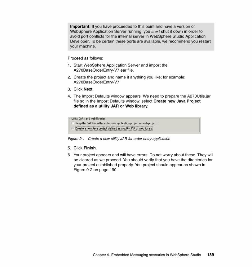
Proceed as follows:
1. Start WebSphere Application Server and import the A270BaseOrderEntry-V7.ear file.
2. Create the project and name it anything you like; for example: A270BaseOrderEntry-V7
3. Click Next.
4. The Import Defaults window appears. We need to prepare the A270Utils.jar file so in the Import Defaults window, select Create new Java Project defined as a utility JAR or Web library.
Figure 9-1 Create a new utility JAR for order entry application
5. Click Finish.
6. Your project appears and will have errors. Do not worry about these. They will be cleared as we proceed. You should verify that you have the directories for your project established properly. You project should appear as shown in Figure 9-2 on page 190.
Important: If you have proceeded to this point and have a version of WebSphere Application Server running, you must shut it down in order to avoid port conflicts for the internal server in WebSphere Studio Application Developer. To be certain these ports are available, we recommend you restart your machine.
Chapter 9. Embedded Messaging scenarios in WebSphere Studio 189
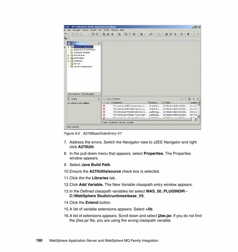
Figure 9-2 A270BaseOrderEntry-V7
7. Address the errors. Switch the Navigator view to J2EE Navigator and right click A270Util.
8. In the pull-down menu that appears, select Properties. The Properties window appears.
9. Select Java Build Path.
10.Ensure the A270Utils/source check box is selected.
11.Click the the Libraries tab.
12.Click Add Variable. The New Variable classpath entry window appears.
13.In the Defined classpath variables list select WAS_50_PLUGINDIR - C:\WebSphere Studio\runtimes\base_V5.
14.Click the Extend button.
15.A list of variable extensions appears. Select +lib.
16.A list of extensions appears. Scroll down and select j2ee.jar. If you do not find the j2ee.jar file, you are using the wrong classpath variable.
190 WebSphere Application Server and WebSphere MQ Family Integration
17.Click OK.
18.Click OK again. The library is added to the project.
At this point there should no longer be any errors in the Tasks window. If there are, repeat the steps above until the errors are cleared.
9.1.2 Define the project resourcesIn WebSphere Studio Application Developer server projects, you can define resources for the servers once they are created. You can either:
� Create a server project and define its resources, or
� Run the A270BaseOrderEntry-V7 project on the server and let WebSphere Studio Application Developer create the server project for you. We used this option.
Proceed as follows:
1. In the J2EE Navigator window, right-click A270BaseOrderEntryEJB and select Run on Server in the pull-down menu.
2. The Server Selection window appears. Click the Create a new server radio button and select server type from the list of servers. We selected Test Environment.
3. Click Finish. A server named server1 is created. Server1 will throw a number of exceptions trying to start because we have not assigned its Java Message Service resources. Ignore them. Close the Web browser.
4. Since we are going to need access to the configuration of server1, create a server perspective. Do this by selecting Windows -> Open Perspective -> Other -> Server. The Server Configuration window appears.
5. In the Server Configuration window, double-click WebSphere V5.0 Test Environment. The WebSphere Server configuration window appears. Everything we need to configure the server is located here, organized into the menu located at the bottom of the window.
Note: If you have another version of WebSphere Application Server running, you will not be able to start server1. This is because the ports it needs will already be in use. Although you can assign new ports across the board, it is far simpler to close down both WebSphere Application Server and WebSphere Studio Application Developer and restart your machine. Then restart WebSphere Studio Application Developer.
Chapter 9. Embedded Messaging scenarios in WebSphere Studio 191
Enable the administration client and the universal test clientThe equivalent to the WebSphere Administrative Console built into WebSphere Studio Application Developer default state is not enabled. Since we will need it, first we change this:
1. In the WebSphere Server window, select Configuration. The WebSphere Server Configuration window appears.
2. Check Enable administration client if it is not checked.
3. Check Enable universal test client if it is not checked.
4. Click File -> Save WebSphere V5.0 Test Environment to save your changes.
Enter security options1. In the WebSphere Server window select Security. The WebSphere Server
Security Options window appears.
2. If it is not checked already, check Enforce Java 2 security.
3. Click Add. The Add JAAS Authentication Entry window appears.
a. For the alias, enter oealias.
b. Provide a user ID and password with full database access. (You set these when you installed your database.)
4. Click File -> Save WebSphere V5.0 Test Environment to save your changes.
Define the JDBC data sourceProceed as follows:
1. Remain in the Server Configuration window and click the Data Source menu.The Data Sources window appears.
2. Next to the JDBC Provider list click Add.
3. For Data Base type, select IBM DB2 (or any database you want to use).
4. In the JDBC Provider type list, select DB2 JDBC Provider (XA). Click Next.
5. The Create a JDBC Provider window appears. Enter the name as DB2-JDBC-TZFORUXA.
6. Verify the classpath is ${DB2_JDBC_DRIVER _PATH}/db2java.zip (or is correct for the database you are using).
Note: We recommend that you get the value of the path variable and verify the db2java.zip file (or its equivalent if you are not using DB2) is there.
192 WebSphere Application Server and WebSphere MQ Family Integration
7. Click Finish.
8. Next we define the JNDI name. In the Data Sources window click Add to the right of the second table.
9. In the window that appears, make sure the data source type is Version 5.0 data source. Click Next.
10.The Modify Data Source window appears. Complete this as follows:
a. Name: TZFORUXA.
b. JNDI Name: jdbc/TZFORUXA.
c. Container-managed authentication alias: oealias.
d. If it is not checked, check Use this data source in container managed persistence (CMP).
Click Next.
11.The Resource Properties window appears. Select the first item in the list, Database Name.
12.Enter the name of the database in the Value text box. Enter TZFORU.
13.Click Finish.
14.Click File -> Save WebSphere V5.0 Test Environment to save your changes.
Your JDBC connection to the TZFORU database is configured.
9.1.3 How to define WebSphere JMS Provider resources for server1JMS resources are also defined for WebSphere Studio Application Developer using the WebSphere Test Environment. To to this proceed as follows:
1. Return to the Server window and click JMS (again, in the menu at the bottom of the window).
2. At the Node level, complete each of the resource lists. For each one, click Add and complete the window. While the names obviously change each time,
Note: You define resources for message providers within one of three scopes. We used Node scope in this example because it is the WebSphere Application Server default. All three scope definitions are exposed in the WebSphere JMS Provider Options window and you do have to take care to use the right one. We recommend that you collapse the cell and node scope sections of the form and use server scope for this exercise.
Chapter 9. Embedded Messaging scenarios in WebSphere Studio 193
do not use the default node or server name where they appear. These appear to be required fields. Instead:
a. For Node name, explicitly enter localhost.
b. For Server name, use server1.
c. Use the JMS resource names found in Table 8-2 on page 169, Table 8-3 on page 169, Table 8-4 on page 169, Table 8-5 on page 170, Table 8-6 on page 170.
d. In addition:
i. For container-managed authentication alias, use oealias
ii. For ClientID, use HighValue
iii. Port type must be QUEUED
3. Complete the JMS Server Settings. These are found below the Node settings (and above the Server settings tables). Click Add and enter the JMS Server Queue values fromTable 8-7 on page 170.
4. Click File -> Save WebSphere V5.0 Test Environment to save your changes.
9.1.4 How to configure the message listenersMessage listeners are configured for the JMS Server itself and we do not have access to this from the perspectives available in the Server Configuration windows. Instead you use the Administrative Console that comes with WebSphere Studio Application Developer.
If you cannot start the Administrative Console for some reason, go back and make sure you have enabled the Admin Console (see page 192). Also check that you have been able to start server1. Use the server Console view to check on this.
Note: In cases where you can use DIRECT, you have to have WebSphere MQ installed and configured. If you use DIRECT here, WebSphere Studio Application Developer will try to start a default queue manager with ‘ ‘ as its name. This will cause the resources to fail to start (resource allocation exceptions) and also produce MQ RC 2058.
194 WebSphere Application Server and WebSphere MQ Family Integration
This part of the process is the same for WebSphere Studio Application Developer as with WebSphere Application Server itself. Proceed as follows:
1. Start the WebSphere Administrative Console and set the URL to the Admin Console, which is:
http://localhost:9090/admin
2. From the navigation menu, select Servers -> Application Servers -> Message Listener Service.
3. For each our the six message listeners listed in“Message listeners” on page 170, click New and fill in the form. Make sure each listener default initial state is started.
4. Remember to save your work before you continue.
Example 9-1 System error: invalid object name
SystemErr R javax.management.RuntimeOperationsException: JMXcr0002E Invalid object name.
Tip: At this point, error messages will appear in your server console in red. These occur as you make changes to the configuration of the running JMS Server. The actual error is shown in Example 9-1. This should disappear the next time you recycle server1.
Chapter 9. Embedded Messaging scenarios in WebSphere Studio 195

196 WebSphere Application Server and WebSphere MQ Family Integration
Chapter 10. Network Deployment scenario
In this chapter, we review the functions of the Deployment Manager and the Node Agents, and discuss managing a cluster from the WebSphere Application Server Administrative Console or the WSAdmin tool. We cover installing and updating applications, security, and handling of resources, such as JMS providers and data sources, in Network Deployment. We wrap up with a discussion about adding additional servers to the cluster.
10
© Copyright IBM Corp. 2003. All rights reserved. 197
10.1 Network Deployment overviewThe necessity for more than one server is at the heart of workload management. We simply start up more server processes on more machines to enable more requests. But then, how do we synchronize, balance, and manage them? Network Deployment in WebSphere Application Server Version 5 provides the answer. WebSphere Application Server Version 5.0 Network Deployment gives us the ability to route requests to multiple server processes, on multiple machines.
Embedded Messaging provides a specific messaging topology. When WebSphere Application Server Version 5 is installed, you have the option of installing the Embedded Messaging Client, or the Embedded Messaging Server and Client (or no messaging components). If the Embedded Messaging Server is installed onto a node, then that node will host a single JMS Server. For two WebSphere applications to be able to communicate using JMS, they must be running in the same “cell”, which is the name given to a cluster of WebSphere Application Server instances that are administered together. In order to exchange JMS messages, the two applications must both connect to the same JMS Server instance. In other words, they must both choose the same node whose JMS Server they are going to use.
10.1.1 Deployment ManagerWebSphere Application Server Version 5 uses XML files for the repository. The Deployment Manager is responsible for managing the repository for the many application server processes that may need access to the same information. The Deployment Manager defines the cell (domain) for WebSphere Application Server Version 5 nodes and servers. All servers that share a common repository are said to be in the same cell.
The XML files maintained by the Deployment Manager are stored in the config directory, such as WAS_install\DeploymentManager\config, and below. As you drill down in the file structure, you will see one directory for each node. Each node will then have a specific subdirectory for each application server process, so you can see the structure of the domain reflected in the file system.
The Deployment Manager communicates with the Node Agent by way of the configured Discovery Address, a port and protocol dedicated to allowing WebSphere Application Server processes to find each other.
10.1.2 Node AgentThe Node Agent is itself an application server process, running a file transfer enterprise application. This application exchanges information with the
198 WebSphere Application Server and WebSphere MQ Family Integration
Deployment Manager, and creates a local copy of all the information that the Deployment Manager sends it.
When configuration changes are made, the Deployment Manager updates the Node Agents in the domain at regular intervals; the default is 1 minute.
With the WebSphere Application Server Administrative Console, you do have the option of running the node independently from the Deployment Manager, which essentially cuts the node off from exchanging information with the domain. You can also remove a node from the topology with the removeNode command line utility.
The Location Service Daemon (LSD) runs in the Node Agent. The LSD has two functions:
� Return the Interoperable ORB Reference (IOR) to the calling application� Maintain the routing table for Enterprise JavaBean workload management
The question sometimes arises about running multiple nodes on one physical box. There is code in the install process to inhibit installation to multiple locations on one physical box. This is a legal (licensing) restriction, not a technical restriction.
10.1.3 CellsWhen you federate a node to the Deployment Manager, the administration application is uninstalled because the changes needed will be done at the Deployment Manager and not locally any more.
The administrative application that runs the Deployment Manager has some function not available at the base server, including the ability to view the entire domain topology. Select Environment and click Configure Cell, then click the Local Topology tab. You can expand the tree view of the domain to see nodes, servers, and clusters, and click these resources to navigate.
The Configuration tab allows you to set the cell discovery protocol and parameters needed for the nodes to communicate with the Deployment Manager, if for some reason the default protocol does not fit into your particular environment.
Tip: You can reinstall the Administrative.ear file, and once again handle local administration, but the changes you make will be overwritten at the next synchronization.
Chapter 10. Network Deployment scenario 199
You can also click Manage Nodes and are presented with a list of configured nodes, essentially a subset of the Configure Cell topology, and you can configure node discovery protocol settings, and view and navigate the node part of the overall topology.
10.1.4 ClustersWebSphere Application Server Version 5 uses a passive template concept since:
� Once a cluster member is created, no changes to the template are propagated.
� After installing applications, the binaries are copied to the nodes during synchronization.
In WebSphere Application Server Version 5, you can no longer change the attributes of a cluster member that causes it to be a cluster member. You are limited as to what properties of that cluster member you can change; the cluster member is an application server. What makes it a cluster member is internal. When you define a cluster member, you can copy an existing application server, and thereby start with all the settings of that server. Then, although you can make certain changes to the cluster member, it will always be a cluster member. There is no way to make a cluster member no longer be a cluster member, except to delete it entirely.
In WebSphere Application Server Version 5, you may install applications to an application server, or to the cluster. However, if an application server is a member of a cluster, you cannot install applications directly to it as if it were a stand-alone. Another difference is that the synchronization process propagates application binaries as needed, so the administrator does not need to manually move EAR files to remote nodes.
10.1.5 ScopeResources, such as Queue Connection Factories, Queue Destinations, JDBC drivers and data sources, can be configured in a distributed environment in the same manner as in the base server. However, there is an additional consideration called scope.
The scope of a resource relates to its visibility from the application server perspective. If you configure a resource at the scope of an application server, only that application server can use the resource. If you configure a resource at the scope of a node, all application servers running on that node can access the resource. If you configure a resource at the scope of a cell, all application servers in the domain may access that resource.
200 WebSphere Application Server and WebSphere MQ Family Integration
There is no requirement that every node in a cell be configured identically. Since classpaths may change from machine to machine, you can enter the classpath as a variable name and define that variable at the cell scope. For those machines where the classpath is different, you can define the same variable at the node scope.
The server scope has precedence over the node and cell scopes, and the node scope has precedence over the cell scope. Objects are created at only one scope, although they might be visible at more than one scope.
10.1.6 Remote file servicesNetwork Deployment provides two remote file services:
� File transfer service� File synchronization service
By default, the file transfer service is always configured and enabled at a Node Agent, so you do not need to take additional steps to configure this service. However, you might need to configure the file synchronization service.
File transfer serviceThe file transfer service enables the moving of files between the network manager and the nodes. It uses the HTTP protocol to transfer files. When you enable security in the WebSphere Application Server product, the file transfer service uses certificate-based mutual authentication. You can use the default key files in a test environment. Ensure that you change the default key file to secure your system.
The ports used for file transfer are defined in the Network Deployment server configuration under its WebContainer HTTP transports.
File synchronization serviceThe file synchronization service ensures that a file set on each node matches that on the Deployment Manager node. This service promotes consistent configuration data across a cell. You can adjust several configuration settings to control file synchronization on individual nodes and throughout a system.
This service runs in the Deployment Manager and Node Agents, and ensures that configuration changes made to the cell repository are propagated to the appropriate node repositories. The cell repository is the master repository and configuration changes made to node repositories are not propagated up to the cell. During a synchronization operation, a Node Agent checks with the Deployment Manager to see if any configuration documents that apply to the
Chapter 10. Network Deployment scenario 201
node have been updated. New or updated documents are copied to the node repository, and deleted documents are removed from the node repository.
The default behavior is for each Node Agent to periodically run a synchronization operation. You can configure the interval between operations or disable the periodic behavior. You can also configure the synchronization service to synchronize a node repository before starting a node on the server.
10.2 Network Deployment scenarioIn the Network Deployment scenario, we use applications that implement Embedded Messaging and work on two individual nodes. The Queue Connection Factory on each node specifies that node as the location of the JMS Server. We change the Queue Connection Factory specifications for one node to use the JMS Server on another node. Now both sets of applications are using the same JMS Server and therefore the same queue. This action allows the sender application to run on one node and the receiver application to run on the other node. While we run our scenario with WebSphere Application Server running on two nodes, we could use WebSphere Studio Application Developer on one node and WebSphere Application Server on the other node.
If you have two application server instances, such as WebSphere Studio Application Developer and WebSphere Application Server, using Embedded Messaging running on the same node, you cannot have both of these instances using the same queue. Since specifying the node is the means to indicate in the Queue Connection Factory which JMS Server to use and since both JMS Servers are running on the same node, there is no way to specify the JMS Server you want to use.
If you have WebSphere Studio Application Developer and WebSphere Application Server installed on the same node, you could use a single installation of WebSphere MQ (instead of Embedded Messaging) to provide messaging system services to both application server instances.
10.2.1 Running on a single nodeEmbedded Messaging provides a specific messaging topology. If the Embedded Messaging server component is installed onto a node, then that node will host a single JMS Server. Figure 10-1 on page 203 shows the sender and receiver applications on Node A communicating with the same JMS Server on Node A, which provides access to the same queue on Node A.
Figure 10-1 on page 203 shows Node A and Node B are in the same cell.
202 WebSphere Application Server and WebSphere MQ Family Integration
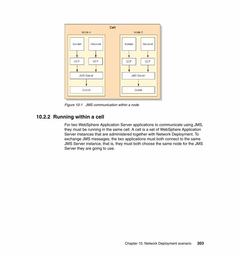
Figure 10-1 JMS communication within a node
10.2.2 Running within a cellFor two WebSphere Application Server applications to communicate using JMS, they must be running in the same cell. A cell is a set of WebSphere Application Server instances that are administered together with Network Deployment. To exchange JMS messages, the two applications must both connect to the same JMS Server instance, that is, they must both choose the same node for the JMS Server they are going to use.
Chapter 10. Network Deployment scenario 203
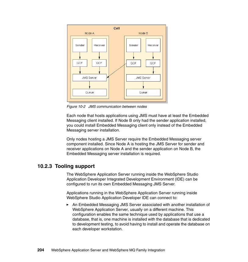
Figure 10-2 JMS communication between nodes
Each node that hosts applications using JMS must have at least the Embedded Messaging client installed. If Node B only had the sender application installed, you could install Embedded Messaging client only instead of the Embedded Messaging server installation.
Only nodes hosting a JMS Server require the Embedded Messaging server component installed. Since Node A is hosting the JMS Server for sender and receiver applications on Node A and the sender application on Node B, the Embedded Messaging server installation is required.
10.2.3 Tooling supportThe WebSphere Application Server running inside the WebSphere Studio Application Developer Integrated Development Environment (IDE) can be configured to run its own Embedded Messaging JMS Server.
Applications running in the WebSphere Application Server running inside WebSphere Studio Application Developer IDE can connect to:
� An Embedded Messaging JMS Server associated with another installation of WebSphere Application Server, usually on a different machine. This configuration enables the same technique used by applications that use a database, that is, one machine is installed with the database that is dedicated to development testing, to avoid having to install and operate the database on each developer workstation.
204 WebSphere Application Server and WebSphere MQ Family Integration
� A WebSphere MQ JMS Provider, just as if the WebSphere Application Server were running outside of WebSphere Studio Application Developer IDE.
The capabilities described above for running Embedded Messaging inside the WebSphere Studio Application Developer IDE also apply to running Embedded Messaging outside the WebSphere Studio Application Developer IDE.
10.2.4 Our environmentWe installed WebSphere Studio Application Developer and WebSphere Application Server with Embedded Messaging on one machine and installed WebSphere Application Server with Embedded Messaging on another machine.
We installed an application, A270EmployeeDetails, that has a sender component, EmployeeDetails, and a receiver component, EmployeeDetailsReply, on the WebSphere Application Server within the WebSphere Studio Application Developer IDE and on the stand-alone WebSphere Application Server.
After we got this application running in each of these individual environments, we included the two application servers on these two different machines into the same cell. We changed the node specification in the Queue Connection Factory from the local machine to the remote machine. Now both applications are using the same JMS Server and therefore the same queue. We can put messages on the queue from either sender component and get messages from the queue from either receiver component.
10.3 Application setup using WebSphere Studio Application Developer
In this section, we show how to use WebSphere Studio Application Developer to configure an existing application to use WebSphere JMS Provider. The application we used is our EmployeeDetails example.
EmployeeDetails uses message queues and was developed using WebSphere MQ JMS Provider. As such, EmployeeDetails is a full-fledged WebSphere MQ application, but key to our purpose is that the API used to communicate with message queues is entirely JMS. We are able to convert the application from WebSphere MQ JMS Provider (WebSphere MQ) to WebSphere JMS Provider (Embedded Messaging) without making a single change to source code.
In this section, we did everything entirely within WebSphere Studio Application Developer.
Chapter 10. Network Deployment scenario 205
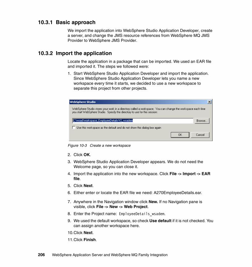
10.3.1 Basic approachWe import the application into WebSphere Studio Application Developer, create a server, and change the JMS resource references from WebSphere MQ JMS Provider to WebSphere JMS Provider.
10.3.2 Import the applicationLocate the application in a package that can be imported. We used an EAR file and imported it. The steps we followed were:
1. Start WebSphere Studio Application Developer and import the application. Since WebSphere Studio Application Developer lets you name a new workspace every time it starts, we decided to use a new workspace to separate this project from other projects.
Figure 10-3 Create a new workspace
2. Click OK.
3. WebSphere Studio Application Developer appears. We do not need the Welcome page, so you can close it.
4. Import the application into the new workspace. Click File -> Import -> EAR file.
5. Click Next.
6. Either enter or locate the EAR file we need: A270EmployeeDetails.ear.
7. Anywhere in the Navigation window click New. If no Navigation pane is visible, click File -> New -> Web Project.
8. Enter the Project name: EmployeeDetails_wsadem.
9. We used the default workspace, so check Use default if it is not checked. You can assign another workspace here.
10.Click Next.
11.Click Finish.
206 WebSphere Application Server and WebSphere MQ Family Integration
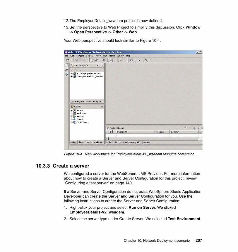
12.The EmployeeDetails_wsadem project is now defined.
13.Set the perspective to Web Project to simplify this discussion. Click Window -> Open Perspective -> Other -> Web.
Your Web perspective should look similar to Figure 10-4.
Figure 10-4 New workspace for EmployeeDetails-V2_wsadem resource conversion
10.3.3 Create a serverWe configured a server for the WebSphere JMS Provider. For more information about how to create a Server and Server Configuration for this project, review “Configuring a test server” on page 140.
If a Server and Server Configuration do not exist, WebSphere Studio Application Developer can create the Server and Server Configuration for you. Use the following instructions to create the Server and Server Configuration:
1. Right-click your project and select Run on Server. We clicked EmployeeDetails-V2_wsadem.
2. Select the server type under Create Server. We selected Test Environment.
Chapter 10. Network Deployment scenario 207
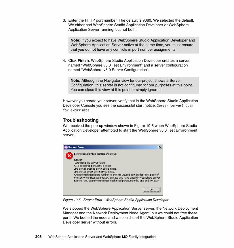
3. Enter the HTTP port number. The default is 9080. We selected the default. We either had WebSphere Studio Application Developer or WebSphere Application Server running, but not both.
4. Click Finish. WebSphere Studio Application Developer creates a server named “WebSphere v5.0 Test Environment” and a server configuration named “WebSphere v5.0 Server Configuration”.
However you create your server, verify that in the WebSphere Studio Application Developer Console you see the successful start notice: Server server1 open for e-business.
TroubleshootingWe received the pop-up window shown in Figure 10-5 when WebSphere Studio Application Developer attempted to start the WebSphere v5.0 Test Environment server.
Figure 10-5 Server Error - WebSphere Studio Application Developer
We stopped the WebSphere Application Server server, the Network Deployment Manager and the Network Deployment Node Agent, but we could not free these ports. We booted the node and we could start the WebSphere Studio Application Developer server without errors.
Note: If you expect to have WebSphere Studio Application Developer and WebSphere Application Server active at the same time, you must ensure that you do not have any conflicts in port number assignments.
Note: Although the Navigator view for our project shows a Server Configuration, this server is not configured for our purposes at this point. You can close this view at this point or simply ignore it.
208 WebSphere Application Server and WebSphere MQ Family Integration
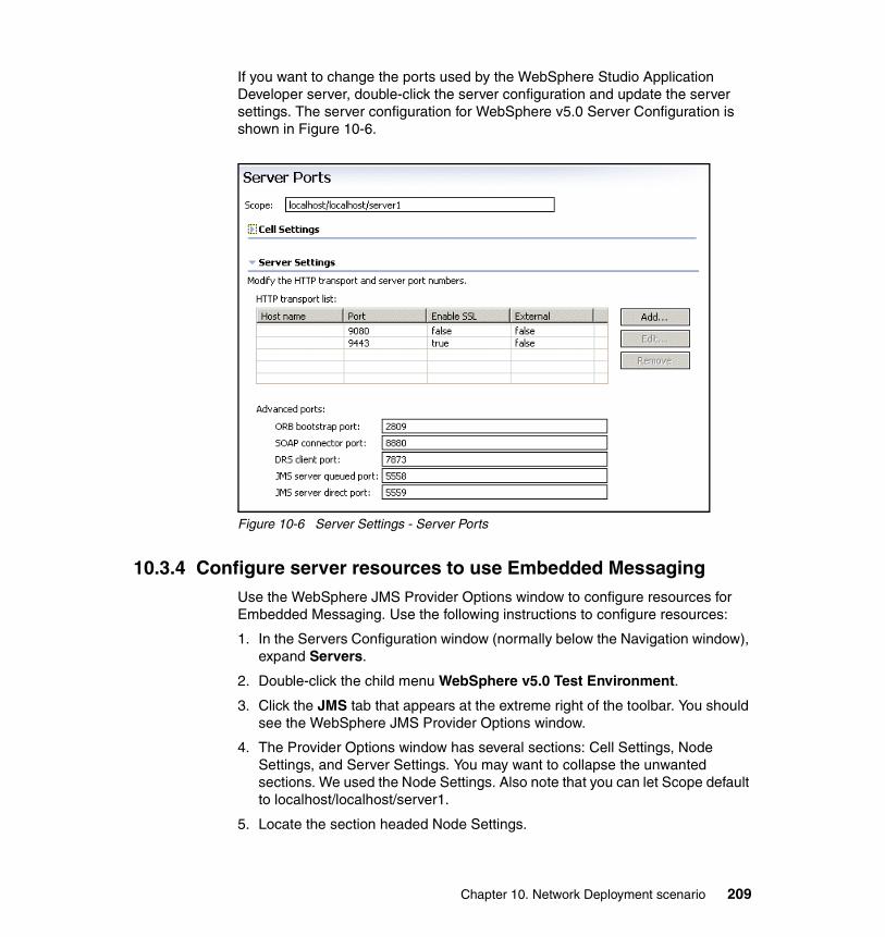
If you want to change the ports used by the WebSphere Studio Application Developer server, double-click the server configuration and update the server settings. The server configuration for WebSphere v5.0 Server Configuration is shown in Figure 10-6.
Figure 10-6 Server Settings - Server Ports
10.3.4 Configure server resources to use Embedded MessagingUse the WebSphere JMS Provider Options window to configure resources for Embedded Messaging. Use the following instructions to configure resources:
1. In the Servers Configuration window (normally below the Navigation window), expand Servers.
2. Double-click the child menu WebSphere v5.0 Test Environment.
3. Click the JMS tab that appears at the extreme right of the toolbar. You should see the WebSphere JMS Provider Options window.
4. The Provider Options window has several sections: Cell Settings, Node Settings, and Server Settings. You may want to collapse the unwanted sections. We used the Node Settings. Also note that you can let Scope default to localhost/localhost/server1.
5. Locate the section headed Node Settings.
Chapter 10. Network Deployment scenario 209
Add JMS connection factoriesBe sure you are in the Node settings section. Then complete the table for JMS Queue Connection Factories. Since our destinations are queues, click Add to add entries into the WASQueueConnectionFactory entries table and use the following instructions:
1. For Name, enter EmployeeDetailsQcf.
2. For JNDI Name, enter JMS/mq/EmployeeDetailsQcf.
3. Enter a description (or bypass because a description is optional).
4. Default the rest of the fields.
5. Click OK.
6. Click Add to add another connection factory.
7. For Name, enter EmployeeDetailsReplyQcf.
8. For JNDI Name, enter JMS/mq/EmployeeDetailsReplyQcf.
9. Click OK.
You have completed the JMS Queue Connection Factory definitions.
Add the JMS queue resourceBe sure that you are in the Node Settings section. Then complete the table for JMS Destinations. Since our destinations are queues, click Add to add entries into the WASQueue entries table and use the following instructions:
1. For Name, enter EmployeeDetailsQ
2. For JNDI Name, enter JMS/mq/EmployeeDetailsQ
3. A description is optional.
4. For node, use localhost.
5. For server name, use server1.
6. Default the rest of the fields.
7. Click OK.
8. Click Add to add another JMS Destination.
9. For Name, enter EmployeeDetailsQ.
10.For JNDI Name, enter JMS/mq/EmployeeDetailsReplyQ.
11.Click OK.
210 WebSphere Application Server and WebSphere MQ Family Integration
Complete the JMS queue resource definition using the following instructions:
1. Scroll down to the Server Settings section to complete the JMS Server Properties table. These settings are in effect for the embedded JMS Server.
2. Click Add to add queue names.
3. The one-line window Add Queue Name appears.
4. For Name, enter EmployeeDetailsQ.
5. Click OK.
You have completed the JMS queue resource definition.
Save the configurationTo save the WebSphere v5.0 Test Environment, select File -> Save WebSphere v5.0 Test Environment (or press Ctrl+S on your keyboard).
10.3.5 Testing the server configurationAlthough the JMS Server itself is probably running, it does not have the names of the queues we have defined. Also the resources we have just added have to be loaded by the application server, server1.
Note: We have defined two different JNDI Queue Connection Factory names pointing to the same Queue Destination because we want to use the same queue, but the sender application, which uses JMS/mq/EmployeeDetailsQ, and receiver application, which uses JMS/mq/EmployeeDetailsReplyQ, use different JNDI names for the queue.
Note: The Queue Name on this pop-up window must match the Queue Name specified in the JMS Queue Destinations. We have one queue, EmployeeDetailsQ. Embedded Messaging creates the JMS resources for you at server launch time. Consequently, the server instance needs to have the names of the message queue resources at that time. If there are other Queue Names in the list, leave them there since they used by other applications.
Chapter 10. Network Deployment scenario 211
Preparing to test Employee DetailsBefore you test the application the first time, complete the definition of the JMS resources for the JMS Server and server1 using the following instructions:
1. Enable the Administrative Console for use with WebSphere Studio Application Developer.
a. In the Server Configuration window, double-click WebSphere v5.0 Test Environment.
b. Click the Configuration tab in the tool bar below the window that appears.
c. Check Enable Administration Client check box, if it is not checked, under Server Configuration section.
d. Save the configuration change and close the window.
e. Restart the server for this change to take effect.
2. Start the Administrative Console:
a. Start a browser either in your WebSphere Studio Application Developer or on your desktop.
b. Use the following URL:
http://<node name>:9090/admin
where node name is simply the host name of your workstation.
3. Set the initial state of the JMS Server to Started using the WebSphere Application Server Administrative Console:
a. Click Servers -> Application Servers -> server1.
b. In the Additional Resources table, click Server components -> JMS Servers.
c. Verify you are in Internal JMS Server pane and, if you are, set the initial state to Started.
Note: If you do not enable the Administration Client, you cannot use the WebSphere Application Server Administrative Console for the WebSphere Studio Application Developer test environment.
Note: The Internal JMS Servers pane should contain the queue name you entered for EmployeeDetails. You can enter the queue names for your applications in this pane. If the queue name is missing or incorrect, enter the correct queue name. You must restart the server for the change to take effect.
212 WebSphere Application Server and WebSphere MQ Family Integration
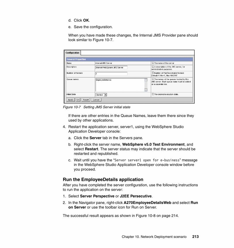
d. Click OK.
e. Save the configuration.
When you have made these changes, the Internal JMS Provider pane should look similar to Figure 10-7.
Figure 10-7 Setting JMS Server initial state
If there are other entries in the Queue Names, leave them there since they used by other applications.
4. Restart the application server, server1, using the WebSphere Studio Application Developer console:
a. Click the Server tab in the Servers pane.
b. Right-click the server name, WebSphere v5.0 Test Environment, and select Restart. The server status may indicate that the server should be restarted and republished.
c. Wait until you have the “Server server1 open for e-business” message in the WebSphere Studio Application Developer console window before you proceed.
Run the EmployeeDetails applicationAfter you have completed the server configuration, use the following instructions to run the application on the server:
1. Select Server Perspective or J2EE Persecutive.
2. In the Navigator pane, right-click A270EmployeeDetailsWeb and select Run on Server or use the toolbar icon for Run on Server.
The successful result appears as shown in Figure 10-8 on page 214.
Chapter 10. Network Deployment scenario 213
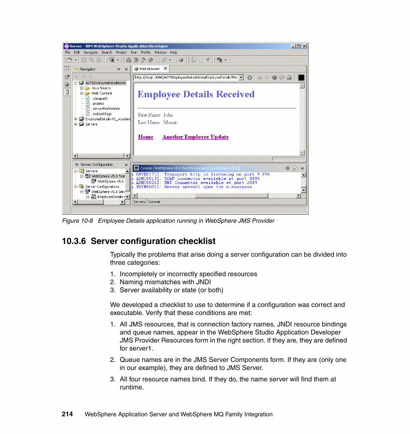
Figure 10-8 Employee Details application running in WebSphere JMS Provider
10.3.6 Server configuration checklistTypically the problems that arise doing a server configuration can be divided into three categories:
1. Incompletely or incorrectly specified resources2. Naming mismatches with JNDI3. Server availability or state (or both)
We developed a checklist to use to determine if a configuration was correct and executable. Verify that these conditions are met:
1. All JMS resources, that is connection factory names, JNDI resource bindings and queue names, appear in the WebSphere Studio Application Developer JMS Provider Resources form in the right section. If they are, they are defined for server1.
2. Queue names are in the JMS Server Components form. If they are (only one in our example), they are defined to JMS Server.
3. All four resource names bind. If they do, the name server will find them at runtime.
214 WebSphere Application Server and WebSphere MQ Family Integration
4. The status of server1 is Ready for e-business with no qualifying messages. If there are any at all, clear them up.
After all these conditions are corrected, you are ready to test the application.
10.3.7 Troubleshooting The following sections cover the error conditions we found, together with a short discussion of what caused them and how we corrected them.
NMSV0605E: A Reference object not foundWe entered resource names and restarted the server. The console shows a normal completion and is open for e-business. At runtime the application throws a NameNotFound exception. From the console log, we identify the error as shown in Example 10-1.
Example 10-1 InitialContextFactory exception
[30/10/02 17:30:20:969 GMT] 687c80db WsServer A WSVR0001I: Server server1 open for e-business[30/10/02 17:37:03:938 GMT] 203680d4 WebGroup I SRVE0180I: [A270EmployeeDetailsWeb] [/A270EmployeeDetailsWeb] [Servlet.LOG]: EmployeeDetailsServlet: init[30/10/02 17:37:07:219 GMT] 203680d4 Helpers W NMSV0605E: A Reference object looked up from the context "java:" with the name "comp/env/jms/mq/EmployeeDetailsQcf" was sent to the JNDI Naming Manager and an exception resulted. Reference data follows:Reference Factory Class Name: com.ibm.ws.naming.util.IndirectJndiLookupObjectFactoryReference Factory Class Location URLs: <null>Reference Class Name: java.lang.ObjectType: JndiLookupInfoContent: JndiLookupInfo: jndiName="JMS/mq/EmployeeDetailsQcf"; providerURL=""; initialContextFactory=""
Explanation: The application looked for a jndiName that does not exist.
Cause: When the Queue Connection Factory name was entered we forgot to click Apply.
Correction: Go back to the Test Environment V5.0.
Cannot send messageEverything seemed OK and the server was restarted and open for e-business. The application could not run and we then got the log entry shown in Example 10-2 on page 216.
Chapter 10. Network Deployment scenario 215
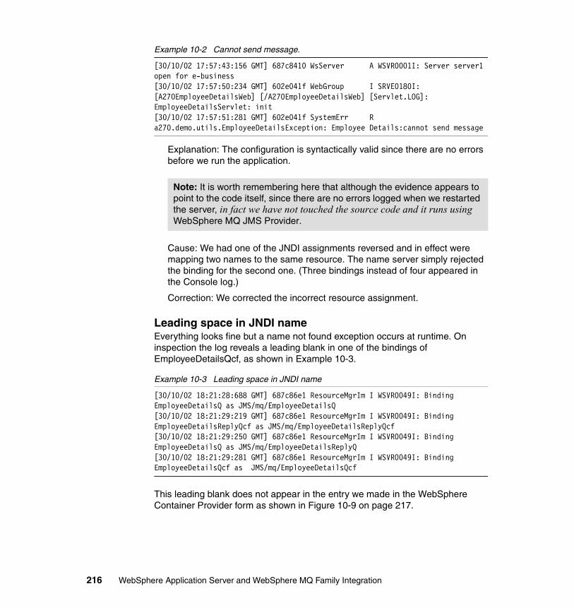
Example 10-2 Cannot send message.
[30/10/02 17:57:43:156 GMT] 687c8410 WsServer A WSVR0001I: Server server1 open for e-business[30/10/02 17:57:50:234 GMT] 602e041f WebGroup I SRVE0180I: [A270EmployeeDetailsWeb] [/A270EmployeeDetailsWeb] [Servlet.LOG]: EmployeeDetailsServlet: init[30/10/02 17:57:51:281 GMT] 602e041f SystemErr R a270.demo.utils.EmployeeDetailsException: Employee Details:cannot send message
Explanation: The configuration is syntactically valid since there are no errors before we run the application.
Cause: We had one of the JNDI assignments reversed and in effect were mapping two names to the same resource. The name server simply rejected the binding for the second one. (Three bindings instead of four appeared in the Console log.)
Correction: We corrected the incorrect resource assignment.
Leading space in JNDI nameEverything looks fine but a name not found exception occurs at runtime. On inspection the log reveals a leading blank in one of the bindings of EmployeeDetailsQcf, as shown in Example 10-3.
Example 10-3 Leading space in JNDI name
[30/10/02 18:21:28:688 GMT] 687c86e1 ResourceMgrIm I WSVR0049I: Binding EmployeeDetailsQ as JMS/mq/EmployeeDetailsQ[30/10/02 18:21:29:219 GMT] 687c86e1 ResourceMgrIm I WSVR0049I: Binding EmployeeDetailsReplyQcf as JMS/mq/EmployeeDetailsReplyQcf[30/10/02 18:21:29:250 GMT] 687c86e1 ResourceMgrIm I WSVR0049I: Binding EmployeeDetailsQ as JMS/mq/EmployeeDetailsReplyQ[30/10/02 18:21:29:281 GMT] 687c86e1 ResourceMgrIm I WSVR0049I: Binding EmployeeDetailsQcf as JMS/mq/EmployeeDetailsQcf
This leading blank does not appear in the entry we made in the WebSphere Container Provider form as shown in Figure 10-9 on page 217.
Note: It is worth remembering here that although the evidence appears to point to the code itself, since there are no errors logged when we restarted the server, in fact we have not touched the source code and it runs using WebSphere MQ JMS Provider.
216 WebSphere Application Server and WebSphere MQ Family Integration
Figure 10-9 Leading blanks do not show in settings
The blank only appears in the Edit form used to provide the parameters for the resource.
J2CA0046E: Method caught an exception - case 1Everything seemed OK and the server was restarted and open for e-business. The application could not run. All four bindings appeared in the log and were correct and server1 was open without errors. At runtime we got the following error in the log entry as shown in Example 10-4.
Example 10-4 J2CA0046E: Method caught an exception
[31/10/02 09:14:01:500 GMT] 68076f73 WsServer A WSVR0001I: Server server1 open for e-business[31/10/02 09:15:54:344 GMT] 7f06af6f WebGroup I SRVE0180I: [A270EmployeeDetailsWeb] [/A270EmployeeDetailsWeb] [Servlet.LOG]: EmployeeDetailsServlet: init[31/10/02 09:15:58:078 GMT] 7f06af6f FreePool E J2CA0046E: Method createManagedConnctionWithMCWrapper caught an exception during creation of the ManagedConnection for resource JMS$EmployeeDetailsQcf, throwing ResourceAllocationException. Original exception: javax.resource.spi.ResourceAdapterInternalException: createQueueConnection failed
Explanation: The application server, server1, was running, but the JMS Server is not running. Remember they are separate! You can explicitly start the JMS Server.
Correction: Verify that the JMS Server Initial State is set to Started and, if necessary, change the Initial State setting. Then JMS Server will start when you restart the application server, server1.
J2CA0046E: Method caught an exception - case 2In a similar case, everything appeared to be fine, but the server failed to start, giving the exception shown in Example 10-5 on page 218.
Chapter 10. Network Deployment scenario 217
Example 10-5 Results of undefined queue name on JMS Server
[31/10/02 09:24:26:344 GMT] 680770aa WsServer A WSVR0001I: Server server1 open for e-business[31/10/02 09:27:34:484 GMT] 32b430b9 WebGroup I SRVE0180I: [A270EmployeeDetailsWeb] [/A270EmployeeDetailsWeb] [Servlet.LOG]: EmployeeDetailsServlet: init[31/10/02 09:27:37:953 GMT] 32b430b9 FreePool E J2CA0046E: Method createManagedConnctionWithMCWrapper caught an exception during creation of the ManagedConnection for resource JMS$EmployeeDetailsQcf, throwing ResourceAllocationException. Original exception: javax.resource.spi.ResourceAdapterInternalException: createQueueConnection failed
at com.ibm.ejs.jms.JMSCMUtils.mapToResourceException(JMSCMUtils.java:123)
Explanation: A queue is not defined in the JMS Server configuration. Inspect the list of queue names known to the JMS Server using the Administrative Console.
Correction: Remember, changes you make to queue names using the WebSphere Studio Application Developer Administrative Console JMS Provider Server Properties form do not correct this problem. In other words, queues are named in that form are not known to the JMS Server. The same queue names must be entered in both forms. Refer to “Add the JMS queue resource” on page 210 for more details.
10.3.8 Moving to WebSphere Application ServerAn application configured to run with the WebSphere JMS Provider will run unmodified in WebSphere Application Server Version 5. Use the following approach to move an application from WebSphere Studio Application Developer to WebSphere Application Server Version 5:
1. Export the EAR file.
2. Deploy to your application server exactly as we did for the WebSphere Studio Application Developer. Refer to 10.3.2, “Import the application” on page 206 for more details.
3. Provide the JNDI and queue names to the application server and to the JMS Server. Queue names for sample applications shipped with WebSphere Application Server may be present in the Configuration form queue names text area.
4. Restart your application server.
5. Check for the bindings and ready (open for e-business) messages.
The details for each step are described in 10.5, “Application setup” on page 241.
218 WebSphere Application Server and WebSphere MQ Family Integration

10.4 Setting up the environmentThis section contains the instructions for setting up Network Deployment in our environment.
10.4.1 Installing Network DeploymentWe installed the Network Deployment code for this project. The installation instructions for the general availability code may be different. Refer to the product documentation or the InfoCenter for the latest installation information.
1. Run the Install.bat file.
2. Select the language and click OK. The default is English. We installed the English version.
3. Click Next on the welcome window.
4. Accept the terms in the license agreement and click Next.
5. Click Next to install all the Network Deployment options. You have the option to deselect the Network Deployment components you do not want to install. Choose from these features:
a. Deployment Manager: Installs the product runtime. It provides high performance and scalability across your deployment environment. It includes multiserver administration, server clustering, load balancing and workload management for hosting highly available e-business applications.
b. Web Services: Installs the UDDI Registry and the Web Services Gateway to provide Web services support for your e-business applications.
i. UDDI Registry: Installs a Version 2 compliant Universal Description, Discovery, And Identification (UDDI) Registry, accessible from the UDDI Registry User Console application, or from SOAP or EJB interfaces.
ii. Web Services Gateway: Includes a gateway between Internet and intranet environments so that clients can invoke Web services safely from outside a firewall. The gateway uses automatic protocol conversion for externalizing Web services.
c. Embedded Messaging: Includes the client necessary for the administration of WebSphere MQ Queues and the mapping of JMS resources into the Deployment Manager JNDI namespace.
We installed the Deployment Manager (on a node that already had WebSphere Application Server installed). We did not install Web Services or the Embedded Messaging (client).
Chapter 10. Network Deployment scenario 219
6. Change the installation directory to C:\WAS\DeploymentManager.
7. Click Next to accept the defaults for node name, host name and cell name or enter your values for these parameters.
Table 10-1 Node name, host name and cell name values
8. Change the user ID if you do not want to use the logon user name, enter the password for the user ID, and click Next to run WebSphere Application Server as a service. If you do want to run the WebSphere Application Server as a service, deselect Run WebSphere Application Server as a service.
9. Click Next to display a summary of options selected.
10.Click Next and wait for the installation to complete.
11.Deselect the checkbox for connecting to the Internet to register and click Next.
12.Click Finish to end the installation process.
13.The WebSphere Application Server First Step is started at the end of the installation process. We verified the installation as shown in Example 10-6.
Example 10-6 WebSphere Application Server First Step IVT
OS: Windows 2000locale: en_GBhostname: ITSOF1cmd.exe /c "C:\WAS\DeploymentManager\bin\ivt"IVTL0095I: defaulting to host ITSOF1 and port 9090IVTL0010I: Connecting to the WebSphere Application Server ITSOF1 on port: 9090IVTL0015I: WebSphere Application Server ITSOF1 is running on port: 9090IVTL0070I: IVT Verification SucceededIVTL0080I: Installation Verification is complete
Tip: We used C:\WAS instead of the default directory, C:\Program Files\WebSphere\AppServer, for the WebSphere Application Server installation. We could have used C:\WAS\AppServer to replace C:\Program Files\WebSphere\AppServer to maintain the same directory hierarchy as the defaults, that is, have the directories, AppServer and DeploymentManager, at the same level in the directory structure.
Parameter Value
Node Name ITSOF1Manager
Host Name or IP Address ITSOF1
Cell Name ITSOF1Network
220 WebSphere Application Server and WebSphere MQ Family Integration
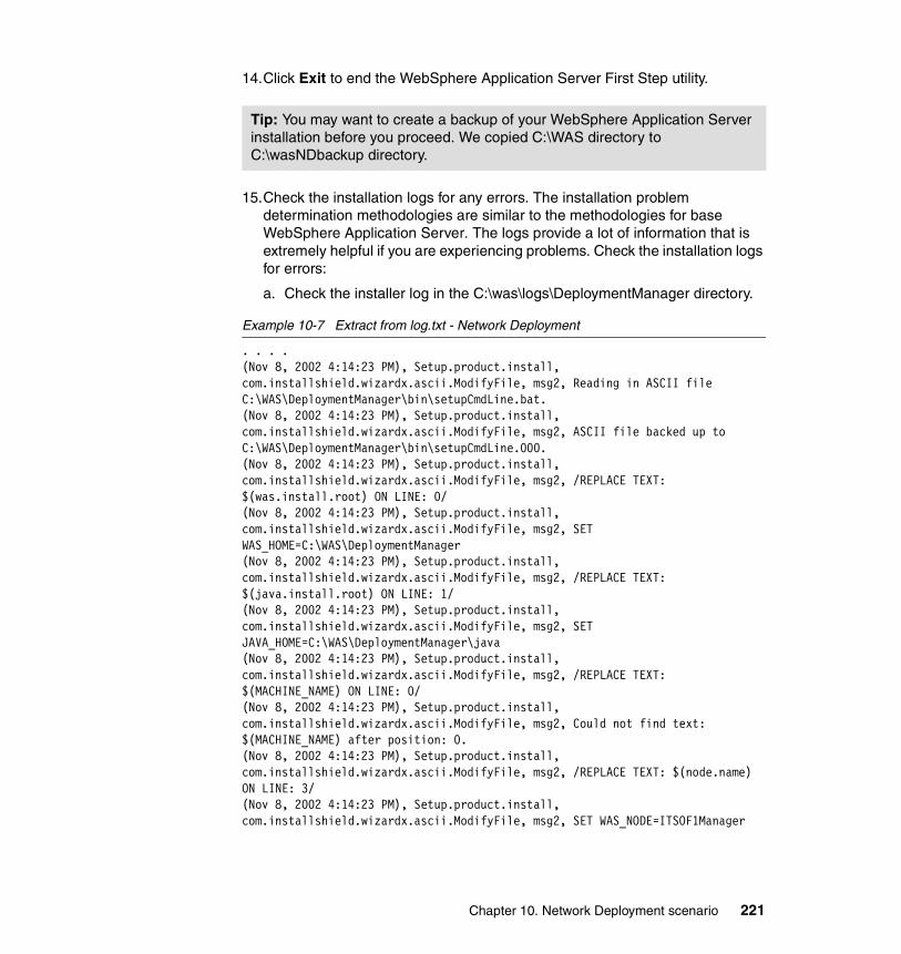
14.Click Exit to end the WebSphere Application Server First Step utility.
15.Check the installation logs for any errors. The installation problem determination methodologies are similar to the methodologies for base WebSphere Application Server. The logs provide a lot of information that is extremely helpful if you are experiencing problems. Check the installation logs for errors:
a. Check the installer log in the C:\was\logs\DeploymentManager directory.
Example 10-7 Extract from log.txt - Network Deployment
. . . .(Nov 8, 2002 4:14:23 PM), Setup.product.install, com.installshield.wizardx.ascii.ModifyFile, msg2, Reading in ASCII file C:\WAS\DeploymentManager\bin\setupCmdLine.bat.(Nov 8, 2002 4:14:23 PM), Setup.product.install, com.installshield.wizardx.ascii.ModifyFile, msg2, ASCII file backed up to C:\WAS\DeploymentManager\bin\setupCmdLine.000.(Nov 8, 2002 4:14:23 PM), Setup.product.install, com.installshield.wizardx.ascii.ModifyFile, msg2, /REPLACE TEXT: $(was.install.root) ON LINE: 0/(Nov 8, 2002 4:14:23 PM), Setup.product.install, com.installshield.wizardx.ascii.ModifyFile, msg2, SET WAS_HOME=C:\WAS\DeploymentManager(Nov 8, 2002 4:14:23 PM), Setup.product.install, com.installshield.wizardx.ascii.ModifyFile, msg2, /REPLACE TEXT: $(java.install.root) ON LINE: 1/(Nov 8, 2002 4:14:23 PM), Setup.product.install, com.installshield.wizardx.ascii.ModifyFile, msg2, SET JAVA_HOME=C:\WAS\DeploymentManager\java(Nov 8, 2002 4:14:23 PM), Setup.product.install, com.installshield.wizardx.ascii.ModifyFile, msg2, /REPLACE TEXT: $(MACHINE_NAME) ON LINE: 0/(Nov 8, 2002 4:14:23 PM), Setup.product.install, com.installshield.wizardx.ascii.ModifyFile, msg2, Could not find text: $(MACHINE_NAME) after position: 0.(Nov 8, 2002 4:14:23 PM), Setup.product.install, com.installshield.wizardx.ascii.ModifyFile, msg2, /REPLACE TEXT: $(node.name) ON LINE: 3/(Nov 8, 2002 4:14:23 PM), Setup.product.install, com.installshield.wizardx.ascii.ModifyFile, msg2, SET WAS_NODE=ITSOF1Manager
Tip: You may want to create a backup of your WebSphere Application Server installation before you proceed. We copied C:\WAS directory to C:\wasNDbackup directory.
Chapter 10. Network Deployment scenario 221
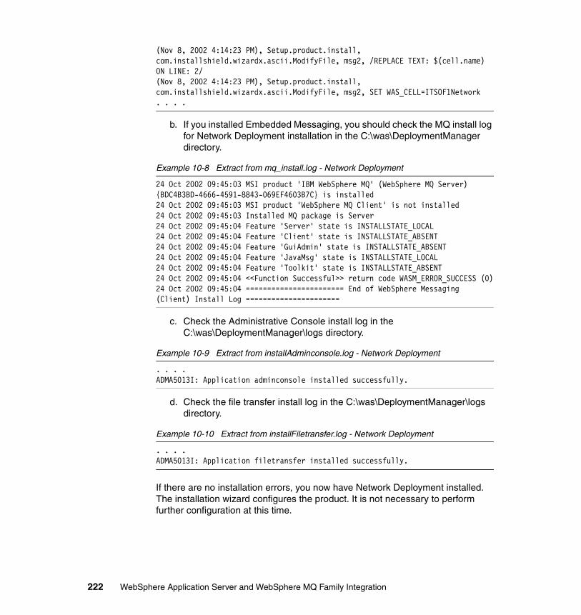
(Nov 8, 2002 4:14:23 PM), Setup.product.install, com.installshield.wizardx.ascii.ModifyFile, msg2, /REPLACE TEXT: $(cell.name) ON LINE: 2/(Nov 8, 2002 4:14:23 PM), Setup.product.install, com.installshield.wizardx.ascii.ModifyFile, msg2, SET WAS_CELL=ITSOF1Network. . . .
b. If you installed Embedded Messaging, you should check the MQ install log for Network Deployment installation in the C:\was\DeploymentManager directory.
Example 10-8 Extract from mq_install.log - Network Deployment
24 Oct 2002 09:45:03 MSI product 'IBM WebSphere MQ' (WebSphere MQ Server) {BDC4B3BD-4666-4591-8843-069EF4603B7C} is installed24 Oct 2002 09:45:03 MSI product 'WebSphere MQ Client' is not installed24 Oct 2002 09:45:03 Installed MQ package is Server24 Oct 2002 09:45:04 Feature 'Server' state is INSTALLSTATE_LOCAL24 Oct 2002 09:45:04 Feature 'Client' state is INSTALLSTATE_ABSENT24 Oct 2002 09:45:04 Feature 'GuiAdmin' state is INSTALLSTATE_ABSENT24 Oct 2002 09:45:04 Feature 'JavaMsg' state is INSTALLSTATE_LOCAL24 Oct 2002 09:45:04 Feature 'Toolkit' state is INSTALLSTATE_ABSENT24 Oct 2002 09:45:04 <<Function Successful>> return code WASM_ERROR_SUCCESS (0)24 Oct 2002 09:45:04 ======================= End of WebSphere Messaging (Client) Install Log ======================
c. Check the Administrative Console install log in the C:\was\DeploymentManager\logs directory.
Example 10-9 Extract from installAdminconsole.log - Network Deployment
. . . .ADMA5013I: Application adminconsole installed successfully.
d. Check the file transfer install log in the C:\was\DeploymentManager\logs directory.
Example 10-10 Extract from installFiletransfer.log - Network Deployment
. . . .ADMA5013I: Application filetransfer installed successfully.
If there are no installation errors, you now have Network Deployment installed. The installation wizard configures the product. It is not necessary to perform further configuration at this time.
222 WebSphere Application Server and WebSphere MQ Family Integration
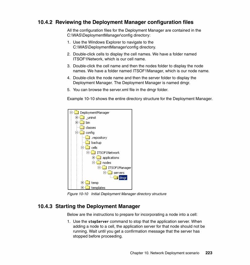
10.4.2 Reviewing the Deployment Manager configuration filesAll the configuration files for the Deployment Manager are contained in the C:\WAS\DeploymentManager\config directory:
1. Use the Windows Explorer to navigate to the C:\WAS\DeploymentManager\config directory.
2. Double-click cells to display the cell names. We have a folder named ITSOF1Network, which is our cell name.
3. Double-click the cell name and then the nodes folder to display the node names. We have a folder named ITSOF1Manager, which is our node name.
4. Double-click the node name and then the server folder to display the Deployment Manager. The Deployment Manager is named dmgr.
5. You can browse the server.xml file in the dmgr folder.
Example 10-10 shows the entire directory structure for the Deployment Manager.
Figure 10-10 Initial Deployment Manager directory structure
10.4.3 Starting the Deployment ManagerBelow are the instructions to prepare for incorporating a node into a cell:
1. Use the stopServer command to stop that the application server. When adding a node to a cell, the application server for that node should not be running. Wait until you get a confirmation message that the server has stopped before proceeding.
Chapter 10. Network Deployment scenario 223
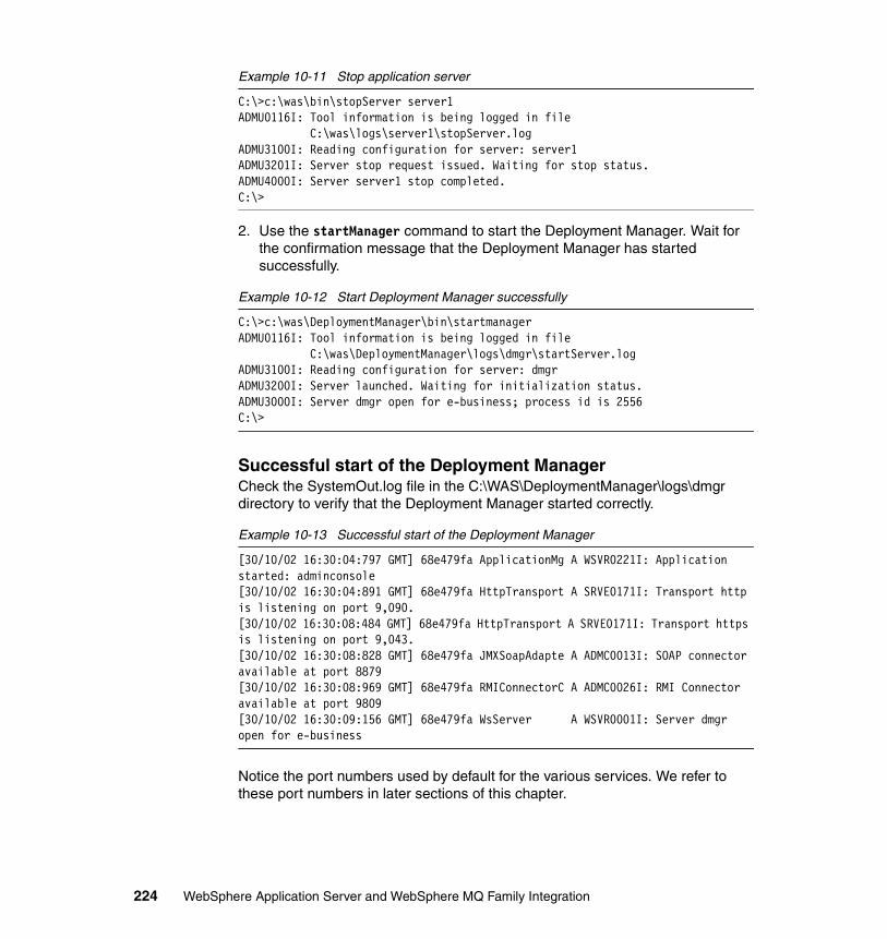
Example 10-11 Stop application server
C:\>c:\was\bin\stopServer server1ADMU0116I: Tool information is being logged in file C:\was\logs\server1\stopServer.logADMU3100I: Reading configuration for server: server1ADMU3201I: Server stop request issued. Waiting for stop status.ADMU4000I: Server server1 stop completed.C:\>
2. Use the startManager command to start the Deployment Manager. Wait for the confirmation message that the Deployment Manager has started successfully.
Example 10-12 Start Deployment Manager successfully
C:\>c:\was\DeploymentManager\bin\startmanagerADMU0116I: Tool information is being logged in file C:\was\DeploymentManager\logs\dmgr\startServer.logADMU3100I: Reading configuration for server: dmgrADMU3200I: Server launched. Waiting for initialization status.ADMU3000I: Server dmgr open for e-business; process id is 2556C:\>
Successful start of the Deployment ManagerCheck the SystemOut.log file in the C:\WAS\DeploymentManager\logs\dmgr directory to verify that the Deployment Manager started correctly.
Example 10-13 Successful start of the Deployment Manager
[30/10/02 16:30:04:797 GMT] 68e479fa ApplicationMg A WSVR0221I: Application started: adminconsole[30/10/02 16:30:04:891 GMT] 68e479fa HttpTransport A SRVE0171I: Transport http is listening on port 9,090.[30/10/02 16:30:08:484 GMT] 68e479fa HttpTransport A SRVE0171I: Transport https is listening on port 9,043.[30/10/02 16:30:08:828 GMT] 68e479fa JMXSoapAdapte A ADMC0013I: SOAP connector available at port 8879[30/10/02 16:30:08:969 GMT] 68e479fa RMIConnectorC A ADMC0026I: RMI Connector available at port 9809[30/10/02 16:30:09:156 GMT] 68e479fa WsServer A WSVR0001I: Server dmgr open for e-business
Notice the port numbers used by default for the various services. We refer to these port numbers in later sections of this chapter.
224 WebSphere Application Server and WebSphere MQ Family Integration
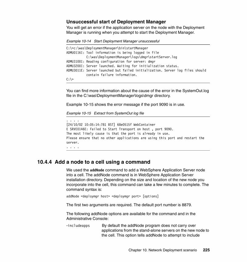
Unsuccessful start of Deployment ManagerYou will get an error if the application server on the node with the Deployment Manager is running when you attempt to start the Deployment Manager.
Example 10-14 Start Deployment Manager unsuccessful
C:\>c:\was\DeploymentManager\bin\startManagerADMU0116I: Tool information is being logged in file C:\was\DeploymentManager\logs\dmgr\startServer.logADMU3100I: Reading configuration for server: dmgrADMU3200I: Server launched. Waiting for initialization status.ADMU3011E: Server launched but failed initialization. Server log files should contain failure information.C:\>
You can find more information about the cause of the error in the SystemOut.log file in the C:\was\DeploymentManager\logs\dmgr directory.
Example 10-15 shows the error message if the port 9090 is in use.
Example 10-15 Extract from SystemOut log file
. . . .[24/10/02 10:05:14:781 BST] 68e0515f WebContainer E SRVE0146E: Failed to Start Transport on host , port 9090. The most likely cause is that the port is already in use. Please ensure that no other applications are using this port and restart the server. . . . .
10.4.4 Add a node to a cell using a commandWe used the addNode command to add a WebSphere Application Server node into a cell. The addNode command is in WebSphere Application Server installation directory. Depending on the size and location of the new node you incorporate into the cell, this command can take a few minutes to complete. The command syntax is:
addNode <deploymgr host> <deploymgr port> [options]
The first two arguments are required. The default port number is 8879.
The following addNode options are available for the command and in the Administrative Console:
-includeapps By default the addNode program does not carry over applications from the stand-alone servers on the new node to the cell. This option tells addNode to attempt to include
Chapter 10. Network Deployment scenario 225
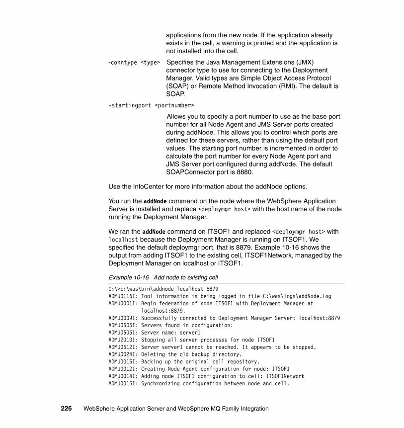
applications from the new node. If the application already exists in the cell, a warning is printed and the application is not installed into the cell.
-conntype <type> Specifies the Java Management Extensions (JMX) connector type to use for connecting to the Deployment Manager. Valid types are Simple Object Access Protocol (SOAP) or Remote Method Invocation (RMI). The default is SOAP.
-startingport <portnumber>
Allows you to specify a port number to use as the base port number for all Node Agent and JMS Server ports created during addNode. This allows you to control which ports are defined for these servers, rather than using the default port values. The starting port number is incremented in order to calculate the port number for every Node Agent port and JMS Server port configured during addNode. The default SOAPConnector port is 8880.
Use the InfoCenter for more information about the addNode options.
You run the addNode command on the node where the WebSphere Application Server is installed and replace <deploymgr host> with the host name of the node running the Deployment Manager.
We ran the addNode command on ITSOF1 and replaced <deploymgr host> with localhost because the Deployment Manager is running on ITSOF1. We specified the default deploymgr port, that is 8879. Example 10-16 shows the output from adding ITSOF1 to the existing cell, ITSOF1Network, managed by the Deployment Manager on localhost or ITSOF1.
Example 10-16 Add node to existing cell
C:\>c:\was\bin\addnode localhost 8879ADMU0116I: Tool information is being logged in file C:\was\logs\addNode.logADMU0001I: Begin federation of node ITSOF1 with Deployment Manager at localhost:8879.ADMU0009I: Successfully connected to Deployment Manager Server: localhost:8879ADMU0505I: Servers found in configuration:ADMU0506I: Server name: server1ADMU2010I: Stopping all server processes for node ITSOF1ADMU0512I: Server server1 cannot be reached. It appears to be stopped.ADMU0024I: Deleting the old backup directory.ADMU0015I: Backing up the original cell repository.ADMU0012I: Creating Node Agent configuration for node: ITSOF1ADMU0014I: Adding node ITSOF1 configuration to cell: ITSOF1NetworkADMU0016I: Synchronizing configuration between node and cell.
226 WebSphere Application Server and WebSphere MQ Family Integration

ADMU0018I: Launching Node Agent process for node: ITSOF1ADMU0020I: Reading configuration for Node Agent process: ITSOF1ADMU0022I: Node Agent launched. Waiting for initialization status.ADMU0030I: Node Agent initialization completed successfully. Process id is: 2736ADMU0523I: Creating Queue Manager for node ITSOF1 on server jmsserverADMU0525I: Details of Queue Manager creation may be seen in the file: createmq.ITSOF1_jmsserver.logADMU9990I:ADMU0300I: Congratulations! Your node ITSOF1 has been successfully incorporated into the ITSOF1Network cell.ADMU9990I:ADMU0306I: Be aware:ADMU0302I: Any cell-level documents from the standalone ITSOF1 configuration have not been migrated to the new cell.ADMU0307I: You might want to:ADMU0303I: Update the configuration on the ITSOF1Network Deployment Manager with values from the old cell-level documents.ADMU9990I:ADMU0306I: Be aware:ADMU0304I: Because -includeapps was not specified, applications installed on the standalone node were not installed on the new cell.ADMU0307I: You might want to:ADMU0305I: Install applications onto the ITSOF1Network cell using wsadmin $AdminApp or the Administrative Console.ADMU9990I:ADMU0003I: Node ITSOF1 has been successfully federated.C:\>
The addNode command does the following actions:
� Copies the base WebSphere Application Server cell configuration to a new cell structure. This new cell structure matches the structure of Deployment Manager.
� Creates a new Node Agent definition for the node that the cell incorporates.
� Sends commands to the Deployment Manager to add the documents from the new node to the cell repository.
� Performs the first configuration synchronization for the new node (ensures it is in sync with the cell).
� Launches the Node Agent process for the new node.
We looked at the cell changes and the procedures are described in 10.4.13, “Exploring the changes” on page 233.
Chapter 10. Network Deployment scenario 227
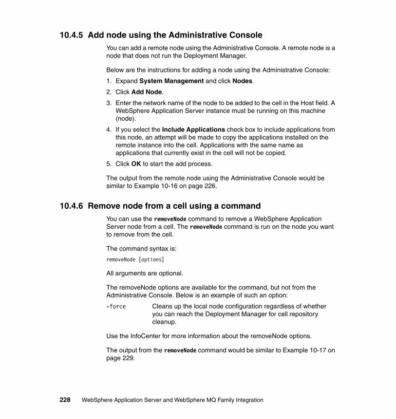
10.4.5 Add node using the Administrative ConsoleYou can add a remote node using the Administrative Console. A remote node is a node that does not run the Deployment Manager.
Below are the instructions for adding a node using the Administrative Console:
1. Expand System Management and click Nodes.
2. Click Add Node.
3. Enter the network name of the node to be added to the cell in the Host field. A WebSphere Application Server instance must be running on this machine (node).
4. If you select the Include Applications check box to include applications from this node, an attempt will be made to copy the applications installed on the remote instance into the cell. Applications with the same name as applications that currently exist in the cell will not be copied.
5. Click OK to start the add process.
The output from the remote node using the Administrative Console would be similar to Example 10-16 on page 226.
10.4.6 Remove node from a cell using a commandYou can use the removeNode command to remove a WebSphere Application Server node from a cell. The removeNode command is run on the node you want to remove from the cell.
The command syntax is:
removeNode [options]
All arguments are optional.
The removeNode options are available for the command, but not from the Administrative Console. Below is an example of such an option:
-force Cleans up the local node configuration regardless of whether you can reach the Deployment Manager for cell repository cleanup.
Use the InfoCenter for more information about the removeNode options.
The output from the removeNode command would be similar to Example 10-17 on page 229.
228 WebSphere Application Server and WebSphere MQ Family Integration
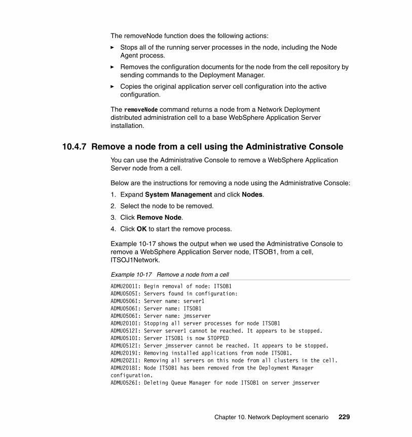
The removeNode function does the following actions:
� Stops all of the running server processes in the node, including the Node Agent process.
� Removes the configuration documents for the node from the cell repository by sending commands to the Deployment Manager.
� Copies the original application server cell configuration into the active configuration.
The removeNode command returns a node from a Network Deployment distributed administration cell to a base WebSphere Application Server installation.
10.4.7 Remove a node from a cell using the Administrative ConsoleYou can use the Administrative Console to remove a WebSphere Application Server node from a cell.
Below are the instructions for removing a node using the Administrative Console:
1. Expand System Management and click Nodes.
2. Select the node to be removed.
3. Click Remove Node.
4. Click OK to start the remove process.
Example 10-17 shows the output when we used the Administrative Console to remove a WebSphere Application Server node, ITSOB1, from a cell, ITSOJ1Network.
Example 10-17 Remove a node from a cell
ADMU2001I: Begin removal of node: ITSOB1 ADMU0505I: Servers found in configuration: ADMU0506I: Server name: server1 ADMU0506I: Server name: ITSOB1 ADMU0506I: Server name: jmsserver ADMU2010I: Stopping all server processes for node ITSOB1 ADMU0512I: Server server1 cannot be reached. It appears to be stopped. ADMU0510I: Server ITSOB1 is now STOPPED ADMU0512I: Server jmsserver cannot be reached. It appears to be stopped. ADMU2019I: Removing installed applications from node ITSOB1. ADMU2021I: Removing all servers on this node from all clusters in the cell. ADMU2018I: Node ITSOB1 has been removed from the Deployment Manager configuration. ADMU0526I: Deleting Queue Manager for node ITSOB1 on server jmsserver
Chapter 10. Network Deployment scenario 229
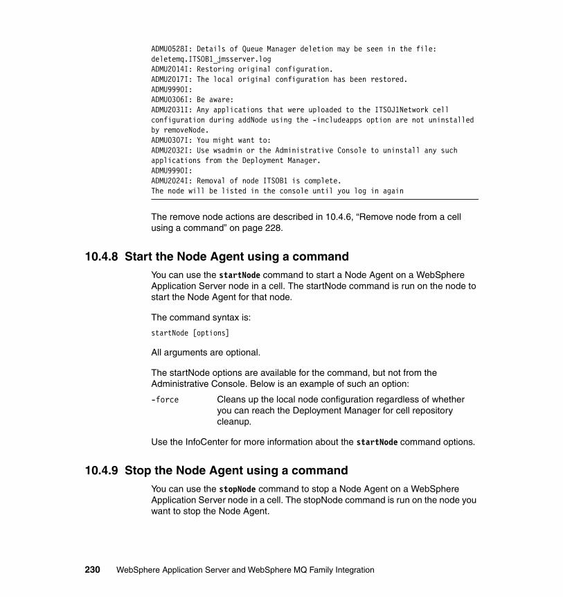
ADMU0528I: Details of Queue Manager deletion may be seen in the file: deletemq.ITSOB1_jmsserver.log ADMU2014I: Restoring original configuration. ADMU2017I: The local original configuration has been restored. ADMU9990I: ADMU0306I: Be aware: ADMU2031I: Any applications that were uploaded to the ITSOJ1Network cell configuration during addNode using the -includeapps option are not uninstalled by removeNode. ADMU0307I: You might want to: ADMU2032I: Use wsadmin or the Administrative Console to uninstall any such applications from the Deployment Manager. ADMU9990I: ADMU2024I: Removal of node ITSOB1 is complete. The node will be listed in the console until you log in again
The remove node actions are described in 10.4.6, “Remove node from a cell using a command” on page 228.
10.4.8 Start the Node Agent using a commandYou can use the startNode command to start a Node Agent on a WebSphere Application Server node in a cell. The startNode command is run on the node to start the Node Agent for that node.
The command syntax is:
startNode [options]
All arguments are optional.
The startNode options are available for the command, but not from the Administrative Console. Below is an example of such an option:
-force Cleans up the local node configuration regardless of whether you can reach the Deployment Manager for cell repository cleanup.
Use the InfoCenter for more information about the startNode command options.
10.4.9 Stop the Node Agent using a commandYou can use the stopNode command to stop a Node Agent on a WebSphere Application Server node in a cell. The stopNode command is run on the node you want to stop the Node Agent.
230 WebSphere Application Server and WebSphere MQ Family Integration
The stopNode command reads the configuration file for the Network Deployment Node Agent process and sends a Java Management Extensions (JMX) command to the Node Agent telling the Node Agent to shut down. By default, the stopNode utility waits for the Node Agent to complete shutdown before it returns control to the command line.
The command syntax is:
stopNode [options]
All arguments are optional.
The stopNode options are available in for the command, but not from the Administrative Console. Below is an example of such an option:
-nowait Tells the stopNode command not to wait for successful shutdown of the Node Agent process.
Use the InfoCenter for more information about the stopNode command options.
10.4.10 Start the Deployment Manager using a commandYou can use the startManager command to start the Deployment Manager on a node. The startManager command is run on the node where the Deployment Manger is installed.
In our environment, we installed the Deployment Manager on a node that had WebSphere Application Server Version 5 installed. The Deployment Manager could be installed on a node without WebSphere Application Server installed. The Deployment Manager communicates with Node Agents on nodes in a cell. The WebSphere Application Server Administrative Console running on the Deployment Manager node can manager the nodes in the cell.
The command syntax is:
startManager [options]
All arguments are optional.
The startManager options are available in for the command, but not from the Administrative Console. Below is an example of such an option:
-trace Generates trace information into a file, using the startManager utility, for debugging purposes.
Use the InfoCenter for more information about the startManager command options.
Chapter 10. Network Deployment scenario 231
10.4.11 Stop the Deployment Manager using a commandYou can use the stopManager command to remove a WebSphere Application Server node from a cell. The stopManager command is run on the node you want to remove from the cell.
The stopManager command reads the configuration file for the network Deployment Manager process and sends a Java Management Extensions (JMX) command to the manager telling it to shut down. By default, the stopManager utility waits for the manager to complete shutdown before it returns control to the command line.
The command syntax is:
stopManager [options]
All arguments are optional.
The stopManager options are available in for the command, but not from the Administrative Console. Below is an example of such an option:
-nowait Tells the stopManager command not to wait for successful shutdown of the Deployment Manager process.
Use the InfoCenter for more information about the stopManager options.
10.4.12 Other Network Deployment commandsBelow is a list of other Network Deployment commands:
serverStatus Use the serverStatus command to obtain the status of one or all of the servers configured on a node.
cleanupNode The cleanupNode command cleans up a node configuration from the cell repository. Only use this command to clean up a node if you have a node defined in the cell configuration, but the node no longer exists.
syncNode The syncNode command forces a configuration synchronization to occur between the node and the Deployment Manager for the cell in which the node is configured. Only use this command when you cannot run the Node Agent because the node configuration does not match the cell configuration.
backupConfig The backupConfig command is a simple utility to back up the configuration of your node to a file. By default, all servers on the node stop before the backup is made so that partially synchronized information is not saved.
232 WebSphere Application Server and WebSphere MQ Family Integration
restoreConfig The restoreConfig command is a simple utility to restore the configuration of your node after backing up the configuration using the backupConfig command. By default, all servers on the node stop before the configuration restores so that a node synchronization does not occur during the restoration. If the configuration directory already exists, it will be renamed before the restoration occurs.
Use the InfoCenter for more information about the command options.
10.4.13 Exploring the changesAdding a node to an existing cell changes the directory structure and the application server Administrative Console contents. In this section, we use the Windows Explorer and the WebSphere Application Server Administrative Console to view these changes. Below are instructions for reviewing these changes:
1. Use the Windows Explorer to navigate to the C:\was\DeploymentManager\config\cells\ITSOF1Network\nodes directory. You should see two nodes: the node that you just federated (ITSOF1) and the Deployment Manager node (ITSOF1Manager).
2. Expand the servers folder under the folder for the node you just added, that is, ITSOF1, to see the servers that are a part of that node.
Figure 10-11 on page 234 shows the directory structure after adding a node.
Chapter 10. Network Deployment scenario 233
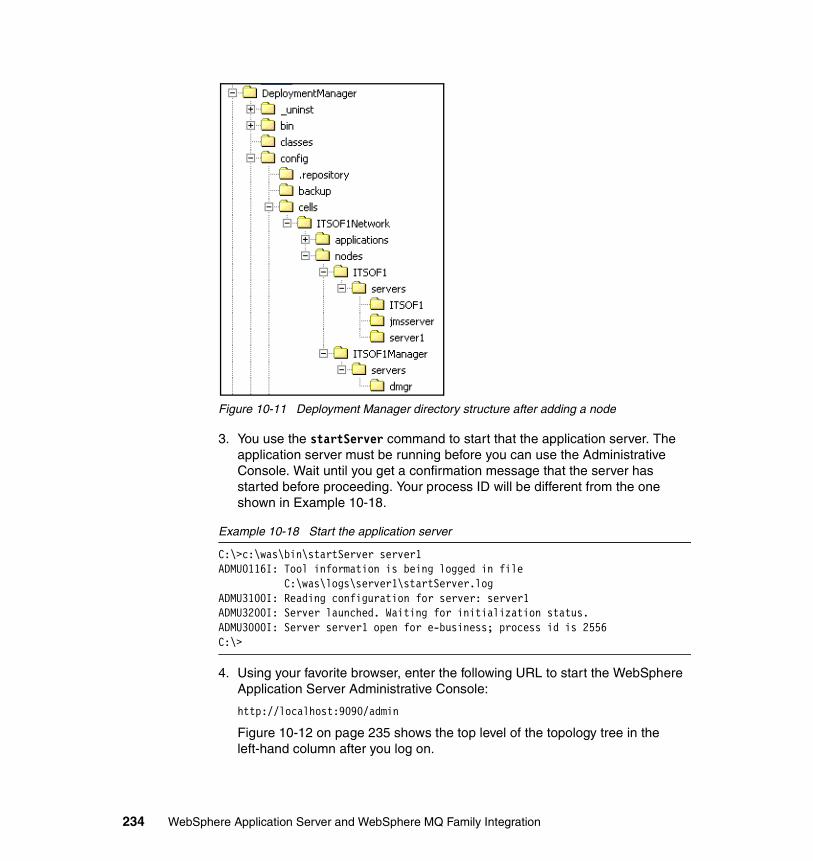
Figure 10-11 Deployment Manager directory structure after adding a node
3. You use the startServer command to start that the application server. The application server must be running before you can use the Administrative Console. Wait until you get a confirmation message that the server has started before proceeding. Your process ID will be different from the one shown in Example 10-18.
Example 10-18 Start the application server
C:\>c:\was\bin\startServer server1ADMU0116I: Tool information is being logged in file C:\was\logs\server1\startServer.logADMU3100I: Reading configuration for server: server1ADMU3200I: Server launched. Waiting for initialization status.ADMU3000I: Server server1 open for e-business; process id is 2556C:\>
4. Using your favorite browser, enter the following URL to start the WebSphere Application Server Administrative Console:
http://localhost:9090/admin
Figure 10-12 on page 235 shows the top level of the topology tree in the left-hand column after you log on.
234 WebSphere Application Server and WebSphere MQ Family Integration
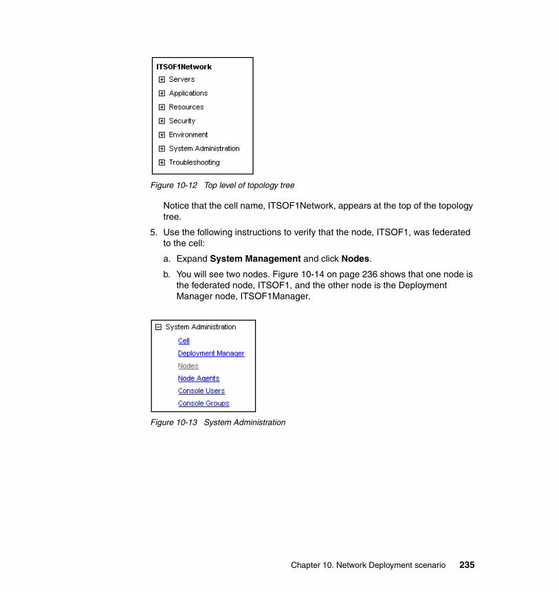
Figure 10-12 Top level of topology tree
Notice that the cell name, ITSOF1Network, appears at the top of the topology tree.
5. Use the following instructions to verify that the node, ITSOF1, was federated to the cell:
a. Expand System Management and click Nodes.
b. You will see two nodes. Figure 10-14 on page 236 shows that one node is the federated node, ITSOF1, and the other node is the Deployment Manager node, ITSOF1Manager.
Figure 10-13 System Administration
Chapter 10. Network Deployment scenario 235
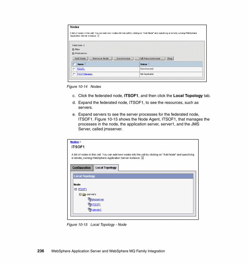
Figure 10-14 Nodes
c. Click the federated node, ITSOF1, and then click the Local Topology tab.
d. Expand the federated node, ITSOF1, to see the resources, such as servers.
e. Expand servers to see the server processes for the federated node, ITSOF1. Figure 10-15 shows the Node Agent, ITSOF1, that manages the processes in the node, the application server, server1, and the JMS Server, called jmsserver.
Figure 10-15 Local Topology - Node
236 WebSphere Application Server and WebSphere MQ Family Integration
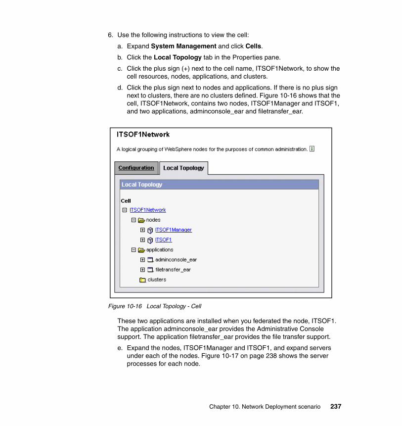
6. Use the following instructions to view the cell:
a. Expand System Management and click Cells.
b. Click the Local Topology tab in the Properties pane.
c. Click the plus sign (+) next to the cell name, ITSOF1Network, to show the cell resources, nodes, applications, and clusters.
d. Click the plus sign next to nodes and applications. If there is no plus sign next to clusters, there are no clusters defined. Figure 10-16 shows that the cell, ITSOF1Network, contains two nodes, ITSOF1Manager and ITSOF1, and two applications, adminconsole_ear and filetransfer_ear.
Figure 10-16 Local Topology - Cell
These two applications are installed when you federated the node, ITSOF1. The application adminconsole_ear provides the Administrative Console support. The application filetransfer_ear provides the file transfer support.
e. Expand the nodes, ITSOF1Manager and ITSOF1, and expand servers under each of the nodes. Figure 10-17 on page 238 shows the server processes for each node.
Chapter 10. Network Deployment scenario 237
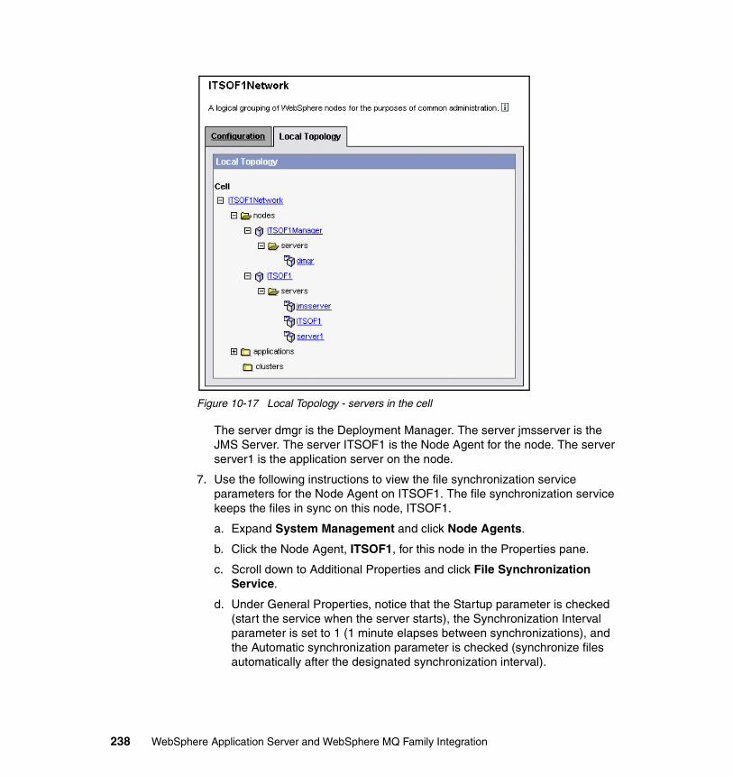
Figure 10-17 Local Topology - servers in the cell
The server dmgr is the Deployment Manager. The server jmsserver is the JMS Server. The server ITSOF1 is the Node Agent for the node. The server server1 is the application server on the node.
7. Use the following instructions to view the file synchronization service parameters for the Node Agent on ITSOF1. The file synchronization service keeps the files in sync on this node, ITSOF1.
a. Expand System Management and click Node Agents.
b. Click the Node Agent, ITSOF1, for this node in the Properties pane.
c. Scroll down to Additional Properties and click File Synchronization Service.
d. Under General Properties, notice that the Startup parameter is checked (start the service when the server starts), the Synchronization Interval parameter is set to 1 (1 minute elapses between synchronizations), and the Automatic synchronization parameter is checked (synchronize files automatically after the designated synchronization interval).
238 WebSphere Application Server and WebSphere MQ Family Integration
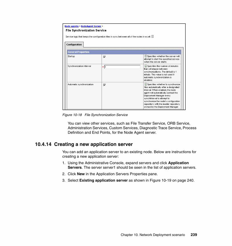
Figure 10-18 File Synchronization Service
You can view other services, such as File Transfer Service, ORB Service, Administration Services, Custom Services, Diagnostic Trace Service, Process Definition and End Points, for the Node Agent server.
10.4.14 Creating a new application serverYou can add an application server to an existing node. Below are instructions for creating a new application server:
1. Using the Administrative Console, expand servers and click Application Servers. The server server1 should be seen in the list of application servers.
2. Click New in the Application Servers Properties pane.
3. Select Existing application server as shown in Figure 10-19 on page 240.
Chapter 10. Network Deployment scenario 239
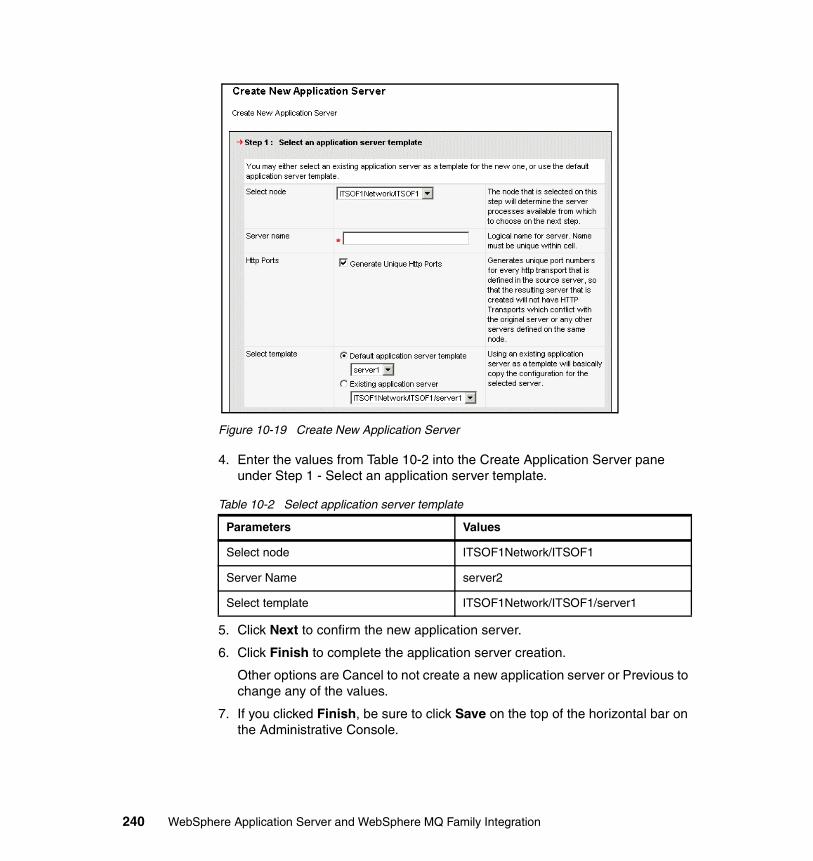
Figure 10-19 Create New Application Server
4. Enter the values from Table 10-2 into the Create Application Server pane under Step 1 - Select an application server template.
Table 10-2 Select application server template
5. Click Next to confirm the new application server.
6. Click Finish to complete the application server creation.
Other options are Cancel to not create a new application server or Previous to change any of the values.
7. If you clicked Finish, be sure to click Save on the top of the horizontal bar on the Administrative Console.
Parameters Values
Select node ITSOF1Network/ITSOF1
Server Name server2
Select template ITSOF1Network/ITSOF1/server1
240 WebSphere Application Server and WebSphere MQ Family Integration
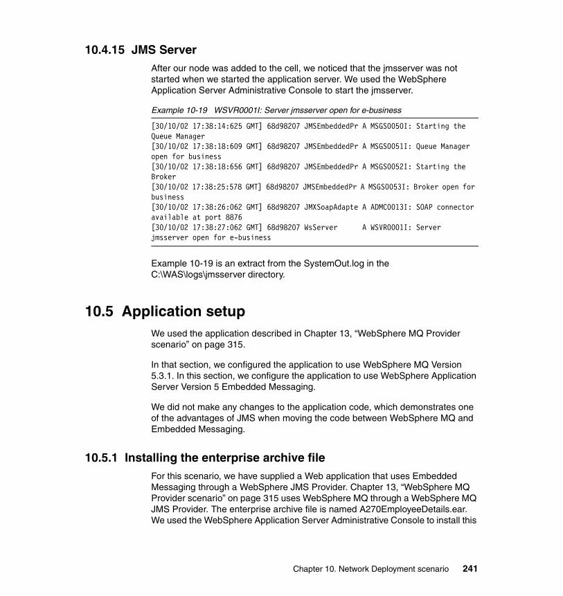
10.4.15 JMS ServerAfter our node was added to the cell, we noticed that the jmsserver was not started when we started the application server. We used the WebSphere Application Server Administrative Console to start the jmsserver.
Example 10-19 WSVR0001I: Server jmsserver open for e-business
[30/10/02 17:38:14:625 GMT] 68d98207 JMSEmbeddedPr A MSGS0050I: Starting the Queue Manager[30/10/02 17:38:18:609 GMT] 68d98207 JMSEmbeddedPr A MSGS0051I: Queue Manager open for business[30/10/02 17:38:18:656 GMT] 68d98207 JMSEmbeddedPr A MSGS0052I: Starting the Broker[30/10/02 17:38:25:578 GMT] 68d98207 JMSEmbeddedPr A MSGS0053I: Broker open for business[30/10/02 17:38:26:062 GMT] 68d98207 JMXSoapAdapte A ADMC0013I: SOAP connector available at port 8876[30/10/02 17:38:27:062 GMT] 68d98207 WsServer A WSVR0001I: Server jmsserver open for e-business
Example 10-19 is an extract from the SystemOut.log in the C:\WAS\logs\jmsserver directory.
10.5 Application setupWe used the application described in Chapter 13, “WebSphere MQ Provider scenario” on page 315.
In that section, we configured the application to use WebSphere MQ Version 5.3.1. In this section, we configure the application to use WebSphere Application Server Version 5 Embedded Messaging.
We did not make any changes to the application code, which demonstrates one of the advantages of JMS when moving the code between WebSphere MQ and Embedded Messaging.
10.5.1 Installing the enterprise archive fileFor this scenario, we have supplied a Web application that uses Embedded Messaging through a WebSphere JMS Provider. Chapter 13, “WebSphere MQ Provider scenario” on page 315 uses WebSphere MQ through a WebSphere MQ JMS Provider. The enterprise archive file is named A270EmployeeDetails.ear. We used the WebSphere Application Server Administrative Console to install this
Chapter 10. Network Deployment scenario 241
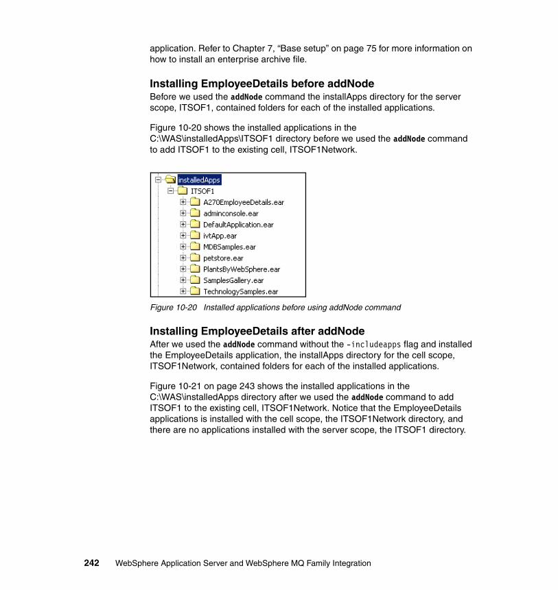
application. Refer to Chapter 7, “Base setup” on page 75 for more information on how to install an enterprise archive file.
Installing EmployeeDetails before addNodeBefore we used the addNode command the installApps directory for the server scope, ITSOF1, contained folders for each of the installed applications.
Figure 10-20 shows the installed applications in the C:\WAS\installedApps\ITSOF1 directory before we used the addNode command to add ITSOF1 to the existing cell, ITSOF1Network.
Figure 10-20 Installed applications before using addNode command
Installing EmployeeDetails after addNodeAfter we used the addNode command without the -includeapps flag and installed the EmployeeDetails application, the installApps directory for the cell scope, ITSOF1Network, contained folders for each of the installed applications.
Figure 10-21 on page 243 shows the installed applications in the C:\WAS\installedApps directory after we used the addNode command to add ITSOF1 to the existing cell, ITSOF1Network. Notice that the EmployeeDetails applications is installed with the cell scope, the ITSOF1Network directory, and there are no applications installed with the server scope, the ITSOF1 directory.
242 WebSphere Application Server and WebSphere MQ Family Integration
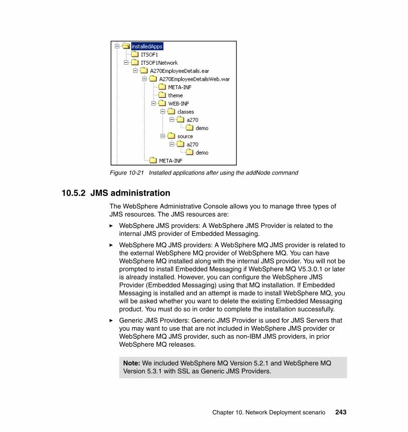
Figure 10-21 Installed applications after using the addNode command
10.5.2 JMS administrationThe WebSphere Administrative Console allows you to manage three types of JMS resources. The JMS resources are:
� WebSphere JMS providers: A WebSphere JMS Provider is related to the internal JMS provider of Embedded Messaging.
� WebSphere MQ JMS providers: A WebSphere MQ JMS provider is related to the external WebSphere MQ provider of WebSphere MQ. You can have WebSphere MQ installed along with the internal JMS provider. You will not be prompted to install Embedded Messaging if WebSphere MQ V5.3.0.1 or later is already installed. However, you can configure the WebSphere JMS Provider (Embedded Messaging) using that MQ installation. If Embedded Messaging is installed and an attempt is made to install WebSphere MQ, you will be asked whether you want to delete the existing Embedded Messaging product. You must do so in order to complete the installation successfully.
� Generic JMS Providers: Generic JMS Provider is used for JMS Servers that you may want to use that are not included in WebSphere JMS provider or WebSphere MQ JMS provider, such as non-IBM JMS providers, in prior WebSphere MQ releases.
Note: We included WebSphere MQ Version 5.2.1 and WebSphere MQ Version 5.3.1 with SSL as Generic JMS Providers.
Chapter 10. Network Deployment scenario 243
The internal JMS provider (Embedded Messaging) runs in a JMS Server process. In the single-server configuration, JMS Server runs within the application server.
In a Network Deployment installation, the JMS Server is basically the broker and additionally manages the queue manager. JMS Server is a peer of the other servers in a given node, and runs in its own JVM. In a Network Deployment configuration, you only have one active JMS Server per node. The JMS Server gets created for you and you only need to configure it. The JMS resources defined in a JMS Server are accessible from anywhere in the cell.
You can have more than one JMS provider per node.
10.5.3 Configuring the WebSphere JMS ProviderThe WebSphere JMS Provider is the built-in JMS Provider provided with WebSphere Application Server Version 5 and is included in the feature known as WebSphere Embedded Messaging.
Naming clients typically use the Java Naming and Directory Interface (JNDI) to perform naming operations. Naming clients can also use the Common Object Request Broker Architecture (CORBA) CosNaming interface. Use these interfaces to look up server application objects that are bound into the name space and obtain references to them. Most Java developers use the JNDI interface.
The application, A270EmployeeDetails, has a component, EmployeeDetails, that collects employee information and writes the data to queue and another component, EmployeeDetailsReply, then retrieves this data from the queue. In Chapter 13, “WebSphere MQ Provider scenario” on page 315 , a separate queue is defined for the send queue and the reply queue. Since you are not permitted to define remote queuing when using Embedded Messaging, we configured the WebSphere JMS Provider to use a single queue.
Add queue definition to WebSphere JMS ProviderUse the following instructions to add the queue definition to WebSphere JMS Provider server component of the application server.
1. Start the WebSphere Administrative Console and log in.
Important: If you do not specify a queue name in this section, Embedded Messaging does not create the queue when the WebSphere Application Server starts. If an Embedded Messaging queue is found that is not in this list, the queue is deleted when WebSphere Application Server starts.
244 WebSphere Application Server and WebSphere MQ Family Integration
2. Expand Servers and click Application Servers to configure the WebSphere Application Server.
3. Click server1 in the Properties pane for Application Servers.
4. Scroll down the Additional Properties section and click Server Components.
5. Click JMS Servers under the Type section and change the configuration properties of the selected JMS Server.
6. Enter the name EmployeeDetailsQ of the queue hosted by this JMS Server in the Queues Name section under General Properties for the Internal JMS Provider. Each queue name is entered on a separate line.
7. Ensure that the initial state (the execution state requested when the server is first started) is Started. If the JMS Server is not started when you run EmployeeDetails application, you will get a “Create Queue Connection Failed” message.
8. Click OK.
9. Click Save.
10.Click Save on the Save to Master Configuration pane to update the master repository with your changes.
11.The server needs to be restarted for these changes to take effect.
Add WebSphere Queue Connection FactoryComplete the following instructions to add a WebSphere Queue Connection Factory to the internal WebSphere JMS Provider:
1. Expand Resources and click WebSphere JMS Provider.
2. Use scope settings under the Configuration tab to limit the availability of resources to a particular cell, node, or server. The default is Node, if the scope has not been changed. You can change the scope by selecting the radio button next to the scope, cell, node or server and clicking Apply.
Resources with cell scope are not migrated to the Network Deployment during the add node process. Ensure that the scope is either node or server. We migrated this resource when we add a node in our Network Deployment section.
Note: The queue name specified here must match the display name for the resource in the Queue Destination definition. For more information, refer to “Add WebSphere Queue Destination” on page 246.
Chapter 10. Network Deployment scenario 245
3. Click WebSphere Queue Connection Factories under Additional Properties for the WebSphere JMS Provider to create connections to the associated JMS provider of JMS Queue Destinations, for point-to-point messaging.
4. Click New to create a new WebSphere Queue Connection Factory. WebSphere Queue Connection Factory is used to manage Queue Connection Factories for the internal WebSphere JMS Provider.
5. Enter EmployeeDetailsQcf for Name (display name for this resource) and JMS/mq/EmployeeDetailsQcf for JNDI name (for this resource).
You can enter an optional description for this resource. Node is the WebSphere node name of the administrative node where the JMS Server runs for this connection factory. Connections that are created by this factory will connect to that JMS Server.
6. Click OK to complete the create of the WebSphere Queue Connection Factory.
7. You may want to save your configuration. Click Save at the top of the pane and click Save on the Save to Master Configuration pane to update the master repository with your changes. The server needs to be restarted for these changes to take effect.
Add WebSphere Queue DestinationComplete the following instructions to add a WebSphere Queue Destination to the internal WebSphere JMS Provider:
1. Expand Resources and click WebSphere JMS Provider.
Note: Sometimes not all the defined Queue Connection Factory names are listed. If you think you have defined Queue Connection Factory names that are not in this list, click WebSphere JMS Provider and then WebSphere Queue Connection Factories again. This behavior is in the WebSphere Application Server Version 5 code and may not be in the code at general availability.
Note: The JNDI name is hard-coded in the EmployeeDetails application.
Note: We will change this Node parameter when we run this application in a multiple-node cell. For the multiple-node cell configuration, we specified the same Node value in the Queue Connection Factory specifications on both nodes.
246 WebSphere Application Server and WebSphere MQ Family Integration
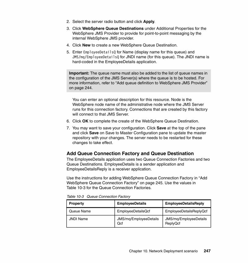
2. Select the server radio button and click Apply.
3. Click WebSphere Queue Destinations under Additional Properties for the WebSphere JMS Provider to provide for point-to-point messaging by the internal WebSphere JMS provider.
4. Click New to create a new WebSphere Queue Destination.
5. Enter EmployeeDetailsQ for Name (display name for this queue) and JMS/mq/EmployeeDetailsQ for JNDI name (for this queue). The JNDI name is hard-coded in the EmployeeDetails application.
You can enter an optional description for this resource. Node is the WebSphere node name of the administrative node where the JMS Server runs for this connection factory. Connections that are created by this factory will connect to that JMS Server.
6. Click OK to complete the create of the WebSphere Queue Destination.
7. You may want to save your configuration. Click Save at the top of the pane and click Save on Save to Master Configuration pane to update the master repository with your changes. The server needs to be restarted for these changes to take effect.
Add Queue Connection Factory and Queue DestinationThe EmployeeDetails application uses two Queue Connection Factories and two Queue Destinations. EmployeeDetails is a sender application and EmployeeDetailsReply is a receiver application.
Use the instructions for adding WebSphere Queue Connection Factory in “Add WebSphere Queue Connection Factory” on page 245. Use the values in Table 10-3 for the Queue Connection Factories.
Table 10-3 Queue Connection Factory
Important: The queue name must also be added to the list of queue names in the configuration of the JMS Server(s) where the queue is to be hosted. For more information, refer to “Add queue definition to WebSphere JMS Provider” on page 244.
Property EmployeeDetails EmployeeDetailsReply
Queue Name EmployeeDetailsQcf EmployeeDetailsReplyQcf
JNDI Name JMS/mq/EmployeeDetailsQcf
JMS/mq/EmployeeDetailsReplyQcf
Chapter 10. Network Deployment scenario 247
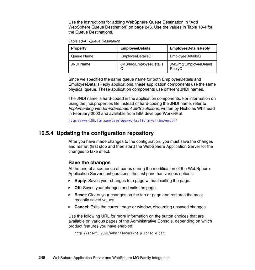
Use the instructions for adding WebSphere Queue Destination in “Add WebSphere Queue Destination” on page 246. Use the values in Table 10-4 for the Queue Destinations.
Table 10-4 Queue Destination
Since we specified the same queue name for both EmployeeDetails and EmployeeDetailsReply applications, these application components use the same physical queue. These application components use different JNDI names.
The JNDI name is hard-coded in the application components. For information on using the jndi.properties file instead of hard-coding the JNDI name, refer to Implementing vendor-independent JMS solutions, written by Nicholas Whithead in February 2002 and available from IBM developerWorks® at:
http://www-106.ibm.com/developerworks/library/j-jmsvendor/
10.5.4 Updating the configuration repositoryAfter you have made changes to the configuration, you must save the changes and restart (first stop and then start) the WebSphere Application Server for the changes to take effect.
Save the changesAt the end of a sequence of panes during the modification of the WebSphere Application Server configurations, the last pane has various options:
� Apply: Saves your changes to a page without exiting the page.
� OK: Saves your changes and exits the page.
� Reset: Clears your changes on the tab or page and restores the most recently saved values.
� Cancel: Exits the current page or window, discarding unsaved changes.
Use the following URL for more information on the button choices that are available on various pages of the Administrative Console, depending on which product features you have enabled:
http://itsof1:9090/admin/secure/help_console.jsp
Property EmployeeDetails EmployeeDetailsReply
Queue Name EmployeeDetailsQ EmployeeDetailsQ
JNDI Name JMS/mq/EmployeeDetailsQ
JMS/mq/EmployeeDetailsReplyQ
248 WebSphere Application Server and WebSphere MQ Family Integration
Click Apply or OK to update the local configuration:
1. Click Save. You can use either the Save button that is in the Message(s) pane or the Save on the horizontal task bar at the top of the Administrative Console window.
2. Click Save on the Save to Master Configuration pane to update the master repository with your changes. The options available on this pane are:
– Save: Update the master repository with your changes
– Discard: Do not update the master repository and discard the changes
– Cancel: Do not update the master repository, but keep the changes
The server needs to be restarted for these changes to take effect.
Stopping the application serverYou can stop the WebSphere Application Server using either of two ways:
1. Via the C:\WAS\bin\stopServer server1 command.
2. By selecting Start -> Programs -> IBM WebSphere -> Application Server v5.0 -> Stop the Server.
Before proceeding, you must wait until you receive a message that WebSphere Application Server has stopped successfully.
Starting the application serverYou can start the WebSphere Application Server using either of two ways:
1. Via the C:\WAS\bin\startServer server1 command.
2. By selecting Start -> Programs -> IBM WebSphere -> Application Server v5.0 -> Start the Server.
You must wait until you receive the started successfully message before proceeding.
10.5.5 Running the EmployeeDetails applicationThere are two components in the EmployeeDetails application:
1. Employee Details Entry: Provides panel for the user to enter employee information, such as first and last name, state of residence, employee number, age, and so forth, and writes the data to a Queue Destination.
Note: This will only work when WebSphere Application Server security is off.
Chapter 10. Network Deployment scenario 249
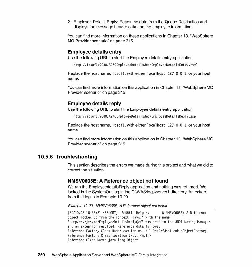
2. Employee Details Reply: Reads the data from the Queue Destination and displays the message header data and the employee information.
You can find more information on these applications in Chapter 13, “WebSphere MQ Provider scenario” on page 315.
Employee details entryUse the following URL to start the Employee details entry application:
http://itsof1:9080/A270EmployeeDetailsWeb/EmployeeDetailsEntry.html
Replace the host name, itsof1, with either localhost, 127.0.0.1, or your host name.
You can find more information on this application in Chapter 13, “WebSphere MQ Provider scenario” on page 315.
Employee details replyUse the following URL to start the Employee details entry application:
http://itsof1:9080/A270EmployeeDetailsWeb/EmployeeDetailsReply.jsp
Replace the host name, itsof1, with either localhost, 127.0.0.1, or your host name.
You can find more information on this application in Chapter 13, “WebSphere MQ Provider scenario” on page 315.
10.5.6 TroubleshootingThis section describes the errors we made during this project and what we did to correct the situation.
NMSV0605E: A Reference object not foundWe ran the EmployeedetailsReply application and nothing was returned. We looked in the SystemOut.log in the C:\WAS\logs\server1 directory. An extract from that log is in Example 10-20.
Example 10-20 NMSV0605E: A Reference object not found
[29/10/02 10:33:51:453 GMT] 7c566fe Helpers W NMSV0605E: A Reference object looked up from the context "java:" with the name "comp/env/jms/mq/EmployeeDetailsReplyQcf" was sent to the JNDI Naming Manager and an exception resulted. Reference data follows:Reference Factory Class Name: com.ibm.ws.util.ResRefJndiLookupObjectFactoryReference Factory Class Location URLs: <null>Reference Class Name: java.lang.Object
250 WebSphere Application Server and WebSphere MQ Family Integration
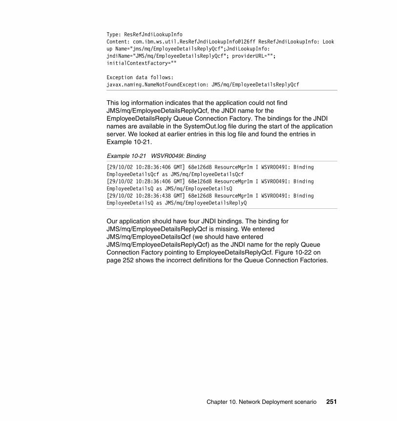
Type: ResRefJndiLookupInfoContent: com.ibm.ws.util.ResRefJndiLookupInfo@126ff ResRefJndiLookupInfo: Look up Name="jms/mq/EmployeeDetailsReplyQcf";JndiLookupInfo: jndiName="JMS/mq/EmployeeDetailsReplyQcf"; providerURL=""; initialContextFactory=""
Exception data follows:javax.naming.NameNotFoundException: JMS/mq/EmployeeDetailsReplyQcf
This log information indicates that the application could not find JMS/mq/EmployeeDetailsReplyQcf, the JNDI name for the EmployeeDetailsReply Queue Connection Factory. The bindings for the JNDI names are available in the SystemOut.log file during the start of the application server. We looked at earlier entries in this log file and found the entries in Example 10-21.
Example 10-21 WSVR0049I: Binding
[29/10/02 10:28:36:406 GMT] 68e126d8 ResourceMgrIm I WSVR0049I: Binding EmployeeDetailsQcf as JMS/mq/EmployeeDetailsQcf[29/10/02 10:28:36:406 GMT] 68e126d8 ResourceMgrIm I WSVR0049I: Binding EmployeeDetailsQ as JMS/mq/EmployeeDetailsQ[29/10/02 10:28:36:438 GMT] 68e126d8 ResourceMgrIm I WSVR0049I: Binding EmployeeDetailsQ as JMS/mq/EmployeeDetailsReplyQ
Our application should have four JNDI bindings. The binding for JMS/mq/EmployeeDetailsReplyQcf is missing. We entered JMS/mq/EmployeeDetailsQcf (we should have entered JMS/mq/EmployeeDetailsReplyQcf) as the JNDI name for the reply Queue Connection Factory pointing to EmployeeDetailsReplyQcf. Figure 10-22 on page 252 shows the incorrect definitions for the Queue Connection Factories.
Chapter 10. Network Deployment scenario 251
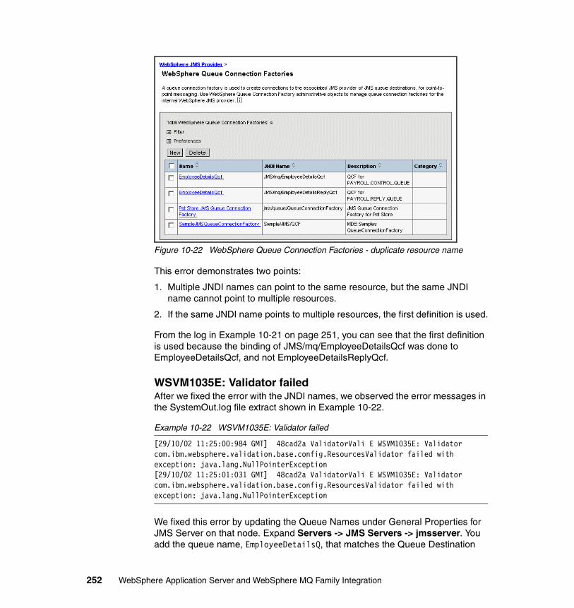
Figure 10-22 WebSphere Queue Connection Factories - duplicate resource name
This error demonstrates two points:
1. Multiple JNDI names can point to the same resource, but the same JNDI name cannot point to multiple resources.
2. If the same JNDI name points to multiple resources, the first definition is used.
From the log in Example 10-21 on page 251, you can see that the first definition is used because the binding of JMS/mq/EmployeeDetailsQcf was done to EmployeeDetailsQcf, and not EmployeeDetailsReplyQcf.
WSVM1035E: Validator failedAfter we fixed the error with the JNDI names, we observed the error messages in the SystemOut.log file extract shown in Example 10-22.
Example 10-22 WSVM1035E: Validator failed
[29/10/02 11:25:00:984 GMT] 48cad2a ValidatorVali E WSVM1035E: Validator com.ibm.websphere.validation.base.config.ResourcesValidator failed with exception: java.lang.NullPointerException[29/10/02 11:25:01:031 GMT] 48cad2a ValidatorVali E WSVM1035E: Validator com.ibm.websphere.validation.base.config.ResourcesValidator failed with exception: java.lang.NullPointerException
We fixed this error by updating the Queue Names under General Properties for JMS Server on that node. Expand Servers -> JMS Servers -> jmsserver. You add the queue name, EmployeeDetailsQ, that matches the Queue Destination
252 WebSphere Application Server and WebSphere MQ Family Integration
name you specified when you defined the JNDI name for the queue. Refer to Table 10-4 on page 248 for the Queue Destination names for the EmployeeDetails application. Click OK and save this change. You must restart the jmsserver and the application server, server1, for these changes to take effect.
You can get more information in “Add queue definition to WebSphere JMS Provider” on page 244.
What happened to the installed applications?After we add the node to the cell, we could not run any applications. We entered the following URL:
http://itsof1:9080/snoop
and received the following message in our browser:
The page cannot be displayedCannot find server or DNS Error
The reason for this error in our situation was that the HTTP port 9080 was not available. We verified the cause by looking at the SystemOut.log file in the C:\WAS\logs\server1 directory. We did not have an entry similar to the entry in Example 10-23. The reason we did not get this message when we started the application server, server1, is that there are no installed applications for this server.
Example 10-23 SRVE0171I: Transport HTTP is listening
[29/10/02 13:35:22:609 GMT] 68e53ca9 HttpTransport A SRVE0171I: Transport http is listening on port 9,080.
After we installed the EmployeeDetails application, we entered the following URL:
http://itsof1:9080/snoop
We received the following message in our browser:
The page cannot be foundHTTP 404 - File not found
The reason for this error in our situation was that the snoop transaction was not in an installed application for this server, server1. We verified the cause by using the WebSphere Application Server Administrative Console; we selected Applications -> Enterprise Applications to display the install applications and WSSamplesGallery was not installed on this server. The snoop transaction is
Chapter 10. Network Deployment scenario 253
part of the WSSamplesGallery enterprise application that is installed when you install WebSphere Application Server.
Check installed applications directoryWe checked the installed applications directory, C:\WAS\installedApps. The installedApps directory now has two directories, ITSOF1 and ITSOF1Network. These directories contain the installed applications for the server scope, ITSOF1, and the node scope, ITSOF1Manager. Neither directory contains any files. Therefore, there are no installed applications either for the server or node scope.
Check with the Administrative ConsoleWe checked the installed applications with the Administrative Console, selecting Applications -> Enterprise Applications. The only applications in the Applications pane were adminconsole and filetransfer, but they were for the server dmgr. There were no installed applications for server1.
How to keep install applications installedWhen you add a node to an existing cell using the addNode command, you should use the -includeapps flag if you want to keep the installed applications on that server. By default the addNode program does not carry over applications from the stand-alone servers on the new node to the cell. The -includeapps option tells addNode to attempt to include applications from the new node. If the application already exists in the cell, a warning is printed and the application is not installed into the cell.
We would not have deleted all the installed applications if we had used the following command to add the node, ITSOF1, to the existing cell, ITSFO1Network:
C:\WAS\bin\addnode localhost 8879 -includeapps
Use the InfoCenter for more information about the addNode options.
http://www-3.ibm.com/software/webservers/appserv/infocenter.html
10.6 Working with clustersClusters are sets of servers that are managed together and participate in workload management. The servers that are members of a cluster can be on different host machines, as opposed to the servers that are part of the same node and must be located on the same host machine.
A cell can have no clusters, one cluster, or multiple clusters.
254 WebSphere Application Server and WebSphere MQ Family Integration
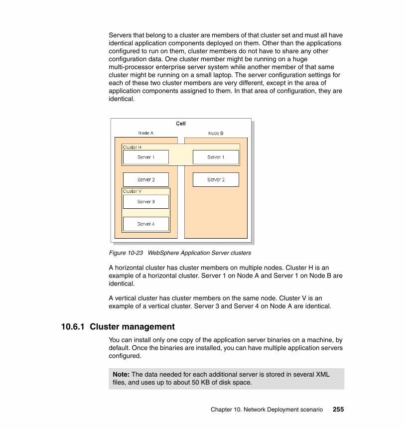
Servers that belong to a cluster are members of that cluster set and must all have identical application components deployed on them. Other than the applications configured to run on them, cluster members do not have to share any other configuration data. One cluster member might be running on a huge multi-processor enterprise server system while another member of that same cluster might be running on a small laptop. The server configuration settings for each of these two cluster members are very different, except in the area of application components assigned to them. In that area of configuration, they are identical.
Figure 10-23 WebSphere Application Server clusters
A horizontal cluster has cluster members on multiple nodes. Cluster H is an example of a horizontal cluster. Server 1 on Node A and Server 1 on Node B are identical.
A vertical cluster has cluster members on the same node. Cluster V is an example of a vertical cluster. Server 3 and Server 4 on Node A are identical.
10.6.1 Cluster managementYou can install only one copy of the application server binaries on a machine, by default. Once the binaries are installed, you can have multiple application servers configured.
Note: The data needed for each additional server is stored in several XML files, and uses up to about 50 KB of disk space.
Chapter 10. Network Deployment scenario 255
Several application servers can run on a single machine, but there is no requirement that they be in the same cluster. Clustering is a logical grouping, not a physical one. All members of a cluster are nearly identical “clones” of a common ancestor.
Cluster members are similar to clones in that they:
� Run the same applications� Share workload� Can be centrally administered
Cluster members are different from clones in that:
� Changes to the template are not propagated to the cluster member� Changes to the cluster change the cluster members
When you create a cluster, you make copies of an existing template. That template will probably be an application server that you have configured. You are offered the option of making that server a member of the cluster.
10.6.2 Creating clustersYou can manage application servers collectively using a cluster. You can create a cluster, view information about clusters, or manage server members on a cluster, using the Server Cluster page on the WebSphere Application Server Administrative Console.
You can choose whether to include an existing server in the cluster. You can create an empty cluster and then add server members to it. To create an empty cluster, do not include an existing server in this cluster. Or, you can create a cluster based on an existing server member, then create and add additional server members to the cluster.
10.6.3 Adding a new cluster memberCreating a new cluster member is very simple: click New, select a template and a node, and click Finish.
For the new cluster member to be recognized, the HTTP server plug-in needs to be regenerated. WebSphere Application Server can be set to automatically regenerate the HTTP plug-in, but that option is not recommended. The default is manual regeneration.
Note: You may want to keep that server available only as a template, because the only way to remove a cluster member is to delete it. Keeping the original server intact allows you to reuse that configuration to rebuild from.
256 WebSphere Application Server and WebSphere MQ Family Integration
10.6.4 Creating cluster membersYou create a cluster member to represent an application server in a cluster. To create a cluster member, view information about cluster members, or manage members of a cluster, use the Cluster Members page on the WebSphere Application Server Administrative Console.
10.6.5 Modification of clustersMaking modifications to cluster members as cluster members, that is, under clusters in the navigation panel, is limited to:
� Install applications� Modify applications� Change server weightings for the routing table (for workload management)� Change the Prefer Local setting (for workload management)
However, you can make any change you wish to a cluster member as an application server.
If you change the routing options, remember to manually regenerate the plug-in to the HTTP server, using the genplugincfg tool. You need not stop the HTTP server because the changes will be loaded when the next ReloadInterval timer expires.
There is no warning message on the WebSphere Application Server Administrative Console to alert the user of the need to update the plug-in.
10.6.6 Deploying and managing applications in a clusterAfter you develop an enterprise application and configure an application server, you can use the Administrative Console to install application files on the server and manage the activity of deployed applications.
To install an enterprise application to a WebSphere Application Server configuration, you can use the Administrative Console or the wsadmin tool. We only installed applications using the Administrative Console. You can use InfoCenter to find information on using wsadmin to install an enterprise application.
Note: There is a feature that can be custom installed, that is, by configuring a property setting that allows the servers to automatically regenerate the plug-in. Since changes to the plug-in are expected to be few, this feature may use clock cycles unnecessarily. We do not recommend using this feature.
Chapter 10. Network Deployment scenario 257
You follow the same instructions for installing an enterprise applications as you used to do the install in a non-cluster environment.
Updating applications to a cluster is done the same as updating applications to a stand-alone server except you select a cluster as the target, rather than a server. Nothing changes until you click Save. Application files (binaries and configuration files) are copied at the next synchronization to all cluster members, that is, servers in the cluster. The behavior can be changed in the WebSphere Application Server Administrative Console. Servers can be ripple-started, that is, restart cluster members one at a time.
There is a redeploy operation for applications that provides a controlled mechanism for updating binaries. Refer to the InfoCenter for more details.
10.6.7 Starting clustersYou can start all members of a cluster at the same time by requesting that the state of a cluster change to Running. That is, you can start all application servers in a server cluster at the same time.
There are two modes of starting the cluster:
� Clicking Start launches the server process of each member of the cluster by calling the Node Agent for each server to start the servers.
� RippleStart combines stopping and starting operations. It first stops and then restarts each member of the cluster.
When you request that all members of a cluster start, the cluster state changes to Partial.start and each server that is a member of that cluster launches, if it is not already running. After all members of the cluster are running, the cluster state becomes Running.
10.6.8 Stopping clustersYou can stop all members of a cluster at the same time by requesting that the state of a cluster change to Stopped. That is, you can stop all application servers in a server cluster at the same time.
Note: Once you start performing the install using the Administrative Console, click Cancel to exit if you decide not to install the application. Do not simply move to another Administrative Console page without first clicking Cancel on an application installation page.
258 WebSphere Application Server and WebSphere MQ Family Integration
There are two modes of stopping the cluster:
� Clicking Stop halts each server in a manner that allows the server to finish existing requests and allows failover to another member of the cluster.
� Choosing Immediate Stop brings down the server quickly without regard to existing requests.
When the stop operation begins, the cluster state changes to Partial.stop. After all servers stop, the cluster state becomes Stopped.
10.6.9 Remove clusterWe removed the nodes from the cluster and removed the cluster to put the nodes back to the state they were in before we created the cell and cluster.
10.7 TermsBelow are some terms used with Network Deployment:
� Vertical scaling
Vertical scaling refers to setting up multiple application servers on one machine, usually by creating cluster members.
� Horizontal scaling
Horizontal scaling exists when there are members of an application server cluster on multiple physical machines. Having cluster members on several machines lets a single application span the machines, yet still present a single system image.
� Clusters
Clusters are identical multiple application server copies. A cluster member is one application server in a cluster. The configuration of each cluster member is based upon the application server that you copied to create the cluster member. You can create all cluster members on the same physical machine or on different machines. Using cluster members can improve the performance of a server, simplify its administration, and enable the use of workload management.
� Cells
Cells are arbitrary, logical groupings of one or more nodes in a WebSphere Application Server distributed network. A cell is a configuration concept, a way for administrators to logically associate nodes with one another.
Chapter 10. Network Deployment scenario 259
� Node
A node is a logical grouping of managed servers. A node usually corresponds to a physical computer system with a distinct IP host address. Node names usually are identical to the host name for the computer.
� Node Agent
A Node Agent manages all WebSphere Application Server servers on a node. The Node Agent represents the node in the management cell.
� Deployment Manager
A Deployment Manager provides a single, central point of administrative control for all elements of the entire WebSphere Application Server distributed cell. A Deployment Manager hosts the Administrative Console for the cell.
260 WebSphere Application Server and WebSphere MQ Family Integration
Chapter 11. XA coordination with WebSphere Application Server
This chapter describes the support in WebSphere Application Server V5 for including messaging operations in transactions. The chapter covers the following topics:
1. A brief overview of transactions, including both local and distributed transactions
2. Support in the JMS API for local transactions involving messaging operations
3. Using JMS messaging by various components supported in WebSphere Application Server V5
4. Support for distributed transactions in WebSphere Application Server V5
5. Architecture of the sample two-phase commit application that demonstrates some of the key messaging and transactional features
6. Deployment of the two-phase commit application
7. The use of the application in demonstrating the features exploited by the application
8. Procedures to verify the behavior of the server-side components
11
© Copyright IBM Corp. 2003. All rights reserved. 261
9. Code snippets from the application that illustrate how to use some of the key features of messaging and transactions in WebSphere Application Server V5
11.1 Introduction to transactionsA transaction is a set of operations that exhibit the following properties (known as ACID):
� Atomicity - either the operations all succeed or fail
� Consistency - irrespective of whether the transaction completes or fails, the resources the operations act on are left in a consistent state (for example, in the case of a database, referential integrity is not violated)
� Isolation - where multiple transactions operating concurrently on shared resources are protected from one another
� Durability - once a transaction has succeeded, the data is persisted and subsequent failures do not affect the result
A transaction has a starting point and an ending point. The initiation and termination of a transaction is called transaction demarcation. Resources that are acted on in a transaction are enlisted as participants in the transaction. In between the start and the endpoints, all the changes made to the resources have the above ACID properties. At the endpoint the transaction can commit, meaning all the changes are made permanent or the transaction can roll back, meaning all the changes are undone.
11.1.1 Local transactionsWhen all the operations in a transaction act on a resource using a single session or connection, the transaction is termed a local transaction. One example of a local transaction is a transaction where multiple operations are initiated on a database using a single connection. Another example is a transaction where multiple JMS send and/or receive commands are issued using a single JMS session.
11.1.2 Distributed transactionsWhen the operations in a transaction possibly act on multiple resources using multiple sessions or connections, the transaction is called a distributed transaction. One example of a distributed transaction is a transaction where operations are performed on two different databases. Another example is a transaction where JMS send and/or receive commands are issued using multiple JMS sessions.
262 WebSphere Application Server and WebSphere MQ Family Integration
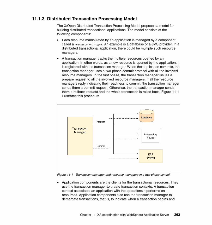
11.1.3 Distributed Transaction Processing ModelThe X/Open Distributed Transaction Processing Model proposes a model for building distributed transactional applications. The model consists of the following components:
� Each resource manipulated by an application is managed by a component called a resource manager. An example is a database or a JMS provider. In a distributed transactional application, there could be multiple such resource managers.
� A transaction manager tracks the multiple resources opened by an application. In other words, as a new resource is opened by the application, it is registered with the transaction manager. When the application commits, the transaction manager uses a two-phase commit protocol with all the involved resource managers. In the first phase, the transaction manager issues a prepare request to all the involved resource managers. If all the resource managers reply indicating their readiness to commit, the transaction manager sends them a commit request. Otherwise, the transaction manager sends them a rollback request and the whole transaction is rolled back. Figure 11-1 illustrates this procedure.
Figure 11-1 Transaction manager and resource managers in a two-phase commit
� Application components are the clients for the transactional resources. They use the transaction manager to create transaction contexts. A transaction context associates an application with the operations it performs on resources. Application components also use the transaction manager to demarcate transactions, that is, to indicate when a transaction begins and
Chapter 11. XA coordination with WebSphere Application Server 263
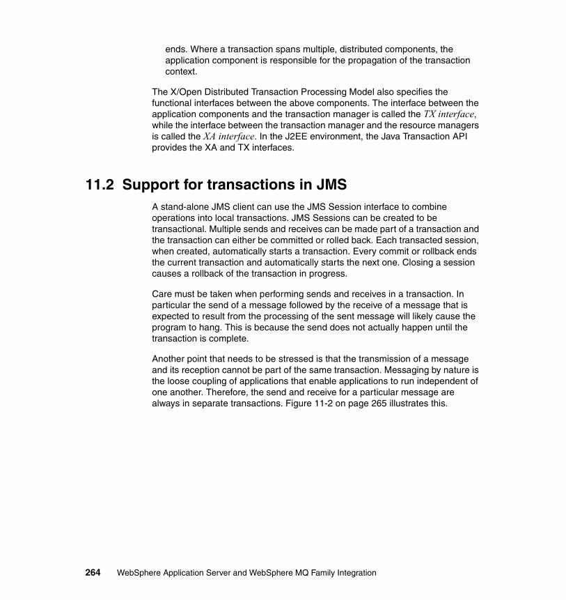
ends. Where a transaction spans multiple, distributed components, the application component is responsible for the propagation of the transaction context.
The X/Open Distributed Transaction Processing Model also specifies the functional interfaces between the above components. The interface between the application components and the transaction manager is called the TX interface, while the interface between the transaction manager and the resource managers is called the XA interface. In the J2EE environment, the Java Transaction API provides the XA and TX interfaces.
11.2 Support for transactions in JMSA stand-alone JMS client can use the JMS Session interface to combine operations into local transactions. JMS Sessions can be created to be transactional. Multiple sends and receives can be made part of a transaction and the transaction can either be committed or rolled back. Each transacted session, when created, automatically starts a transaction. Every commit or rollback ends the current transaction and automatically starts the next one. Closing a session causes a rollback of the transaction in progress.
Care must be taken when performing sends and receives in a transaction. In particular the send of a message followed by the receive of a message that is expected to result from the processing of the sent message will likely cause the program to hang. This is because the send does not actually happen until the transaction is complete.
Another point that needs to be stressed is that the transmission of a message and its reception cannot be part of the same transaction. Messaging by nature is the loose coupling of applications that enable applications to run independent of one another. Therefore, the send and receive for a particular message are always in separate transactions. Figure 11-2 on page 265 illustrates this.
264 WebSphere Application Server and WebSphere MQ Family Integration
Figure 11-2 Transmission and reception of a message in two separate transactions
11.3 Support for JMS messagingBoth Web and EJB components in WebSphere Application Server V5 can send and receive JMS messages synchronously in the same manner as stand-alone clients. However the use of synchronous receives in Web and EJB components is discouraged, because it ties up server resources. WebSphere Application Server V5 application clients function just like stand-alone application clients. They can do synchronous sends and receives as well as asynchronous message handling.
11.3.1 Asynchronous message handling in message-driven beansWebSphere Application Server V5 supports a special type of EJB called a message-driven bean (MDB) that supports asynchronous handling of incoming messages. The messages can be retrieved either from a queue or a topic. An MDB has a single method (onMessage) that is invoked asynchronously and passed the incoming message as a parameter.
The setup of an MDB is quite different from that of a stand-alone JMS client that performs asynchronous message handling. To manage MDBs, WebSphere Application Server V5 provides a listener manager that manages a pool of listener threads. One listener is allocated to each MDB that runs. The listener performs the following steps on behalf of the MDB:
1. Creates pools of sessions and threads for incoming messages.
2. Creates a message or topic consumer using the connection factory and queue or topic specified for the MDB at deployment time.
Chapter 11. XA coordination with WebSphere Application Server 265
3. If specified, starts a transaction before retrieving a message and committing or rolling back the transaction after the message is processed.
4. Upon the arrival of an incoming message, invokes the onMessage method using a session and a thread allocated from the pools. This allows incoming messages to be processed in parallel. Therefore, the application should not rely on the order of delivery of messages for correct behavior.
The developer of the MDB has to implement the onMessage method to handle the incoming messages. In addition, methods such as ejbCreate and ejbRemove can be used to populate and flush a cache of frequently used information such as JMS connections or references to session or entity beans.
11.4 Support for transactionsThe Web and EJB components in WebSphere Application Server V5 use global transactions. This enables them to involve multiple resources in a transaction or multiple, distributed components in a transaction. For instance, a Web component may start a transaction and update two different databases, send a JMS message, and invoke a function in an ERP application before committing the transaction. For session and message-driven EJBs, transactions can either be container-managed or bean-managed.
11.4.1 Container-managed transactionsThe container automatically performs the transaction demarcation for the bean. The bean methods need to be given an appropriate transaction attribute at the time of developing or packaging the bean into an application. If a bean method must run as part of a transaction it should be given the Required attribute. In this case, if a transaction exists when the method is invoked it is used. Otherwise, a new transaction is created before the method is called and committed or rolled back when the method completes.
11.4.2 Bean-managed transactionsThe bean developer needs to acquire a reference to the Javax.Transaction.UserTransaction interface. The interface supports methods to begin, commit, and roll back the transaction as well as to mark the transaction for a rollback. These methods can then be issued by the bean developer to perform transaction demarcation, as well as to control and check the transaction state.
266 WebSphere Application Server and WebSphere MQ Family Integration
11.4.3 MDBs with container-managed transactionsInformation that is specific to MDBs when using container-managed transactions is discussed in this section.
Controlling/checking transaction stateIt is possible to either set or check the transaction state for an MDB with a container-managed transaction, as shown in Example 11-1.
Example 11-1 Container-managed transaction
public void onMessage( javax.jms.Message msg ) {...
getMessageDrivenContext().setRollbackOnly(); // causes the transaction to be rolled back by the container
...boolean rollbackTrue = getMessageDrivenContext().getRollbackOnly();
// returns true if transaction has been marked for rollback
Transactional property of incoming messageFor an MDB deployed with container-managed transactions, the process of receiving the incoming message and starting the onMessage method becomes part of the transaction. So, if the transaction is rolled back for some reason, the message being processed is not acknowledged by the container and is therefore redelivered by the JMS provider.
11.4.4 MDBs with bean-managed transactionsInformation specific to MDBs when using bean-managed transactions is discussed in this section.
Controlling/checking of transaction stateThe container does not create a transaction automatically for the bean. Code within the onMessage method can use the UserTransaction interface to perform transaction demarcation as well as to control and check the transaction state as shown in Example 11-2.
Example 11-2 Bean-managed transaction
public void onMessage( javax.jms.Message msg ) {...javax.Transaction.UserTransaction userTrans =
getMessageDrivenContext().getUserTransaction();...userTrans.begin();...
Chapter 11. XA coordination with WebSphere Application Server 267
userTrans.setRollbackOnly();...boolean rollbackTrue = userTrans.getRollbackOnly();...userTrans.rollback();...userTrans.commit();
Transactional property of incoming message
For an MDB with bean-managed transaction, the process of handling the incoming message is outside of any transaction created by the user code. The container is responsible for handling the acknowledgment for the incoming message. The acknowledgment mode to be used (AUTO_ACKNOWLEDGE which is the default or DUPS_OK_ACKNOWLEDGE) can be specified at the time of developing or assembling the MDB into an application. If the transaction is rolled back by calling the rollback method as shown in the above example, the container acknowledges the message so it is not redelivered. In all other circumstances, including a rollback triggered by the setRollbackOnly method, a redelivery is attempted.
11.4.5 Creation of a new JMS session in a transactionWithin an EJB method that is running within a transaction, the parameters passed in when creating a new JMS session are ignored. This is because the new session is now a resource that is registered with the transaction and must be able to participate in the transaction. The container assumes responsibility for acknowledging any messages received that are associated with the new session.
11.4.6 Use of XA resources in a transactionIf there are multiple resources registered in a transaction, they all need to be XA-compliant in order to participate in the two-phase commit protocol used by the transaction manager in completing the transaction.
11.5 Architecture of two-phase commit application Two versions of an example application were developed to demonstrate some of the key features of WebSphere Application Server V5 that support messaging and transactions. The two versions differ only in the implementation of one message-driven bean. One version implements the message-driven bean using
268 WebSphere Application Server and WebSphere MQ Family Integration
container-managed transactions, while the other version implements the same message-driven bean using bean-managed transactions.
The application basically implements the scenario described in 6.4.5, “Assuring consistency between distributed resources” on page 73. The scenario describes an application that confirms an order in a database and puts a message on a queue all in one transaction. The application implements an extension of the scenario and is shown in Figure 11-3 on page 270.
Chapter 11. XA coordination with WebSphere Application Server 269
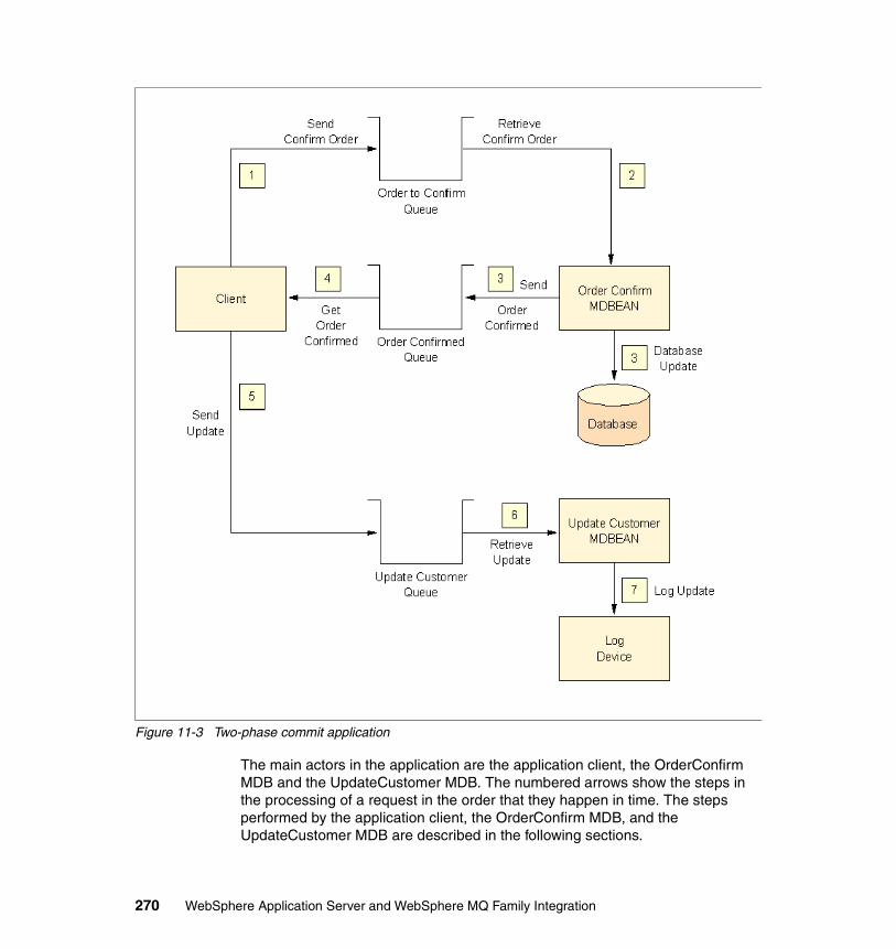
Figure 11-3 Two-phase commit application
The main actors in the application are the application client, the OrderConfirm MDB and the UpdateCustomer MDB. The numbered arrows show the steps in the processing of a request in the order that they happen in time. The steps performed by the application client, the OrderConfirm MDB, and the UpdateCustomer MDB are described in the following sections.
270 WebSphere Application Server and WebSphere MQ Family Integration
11.5.1 Steps performed by the application clientThe application client essentially demonstrates the use of local transactions containing JMS operations. It performs the following steps:
1. Sends an order ID input by the user to the OrderConfirm MDB
2. Commits the send so that a new transaction is started
3. Waits for a message to be sent back in response by the OrderConfirm MDB
4. Sends a copy of the response to the UpdateCustomer MDB
5. Commits the current transaction, which consists of receiving the response from the OrderConfirm MDB and sending the update to the UpdateCustomer MDB
11.5.2 Steps performed by the OrderConfirm MDBThe two versions of the application differ in the implementation of the OrderConfirm MDB as described earlier. The functional behavior of the MDB is the same in both versions. The OrderConfirm MDB demonstrates the two-phase commit capability for global transactions. The steps are as follows:
1. If the incoming message is a redelivery, discard it and return.
2. Retrieve the order ID from the incoming message.
3. Locate the entity bean for the given order ID.
4. Set the status of the order entity bean to Confirmed. This constitutes the operation on a database resource in the global transaction.
5. Acquire a new JMS session and send a message in response to the application client indicating successful update of the order (this constitutes the operation on a JMS resource in the global transaction).
11.5.3 Steps performed by the UpdateCustomer MDBThe purpose of this MDB is to validate that a message is really sent by the application client once it receives the response from the OrderConfirm MDB and that the local transaction at the application client is successful. The steps performed by this MDB are:
1. Write the contents of the received message to a log file
This completes the discussion of the architecture of the two-phase commit application.
Chapter 11. XA coordination with WebSphere Application Server 271
11.6 Deployment of two-phase commit applicationInstructions on obtaining the application and deploying it on base WebSphere Application Server V5 are given in this section. Where extra detail for any particular step is needed with regard to a procedure in base WebSphere Application Server V5, a reference to the appropriate set of instructions listed elsewhere in the book is given.
11.6.1 Instructions to download applicationThe application is part of the additional materials downloadable from the IBM ITSO Redbooks Web site. The version where the OrderConfirm MDB uses container-managed transactions is in the file named TwoPCAppCmt.ear. The version where the OrderConfirm MDB uses bean-managed transactions is in the file named TwoPCAppBmt.ear. The instructions for deployment are the same for both. The files can be installed in a suitable directory on the target machine. For the purpose of this discussion, assume that the files are stored in c:\temp.
11.6.2 Database setupThe application uses the same database and schema used by the order entry application described in Chapter 7, “Base setup” on page 75. The application comes configured to use the TZFORUXA data source. Its creation is described in 8.3.3, “Connecting WebSphere Application Server to the database” on page 159. It is recommended that the application be deployed to use this data source.
The application needs some order records to exist in the database. These records can be created by using the order entry application. The recommended procedure is to get the order entry application running and to create some orders in the database before running this application.
11.6.3 Creation of JMS entitiesEach version of the order entry application needs one Queue Connection Factory and three queues to be created. The following sections list the components of each type that need to be created.
Queue Connection FactoriesThe two-phase commit application uses the Queue Connection Factories shown in Table 11-1 on page 273.
272 WebSphere Application Server and WebSphere MQ Family Integration
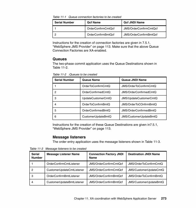
Table 11-1 Queue connection factories to be created
Instructions for the creation of connection factories are given in 7.5.1, “WebSphere JMS Provider” on page 113. Make sure that the above Queue Connection Factories are XA-enabled.
QueuesThe two-phase commit application uses the Queue Destinations shown in Table 11-2.
Table 11-2 :Queues to be created
Instructions for the creation of these Queue Destinations are given in7.5.1, “WebSphere JMS Provider” on page 113.
Message listenersThe order entry application uses the message listeners shown in Table 11-3.
Table 11-3 Message listeners to be created
Serial Number Qcf Name Qcf JNDI Name
1 OrderConfirmCmtQcf JMS/OrderConfirmCmtQcf
2 OrderConfirmBmtQcf JMS/OrderConfirmBmtQcf
Serial Number Queue Name Queue JNDI Name
1 OrderToConfirmCmtQ JMS/OrderToConfirmCmtQ
2 OrderConfirmedCmtQ JMS/OrderConfirmedCmtQ
3 UpdateCustomerCmtQ JMS/UpdateCustomerCmtQ
4 OrderToConfirmBmtQ JMS/OrderToCOnfirmBmtQ
5 OrderConfirmedBmtQ JMS/OrderConfirmedBmtQ
6 CustomerUpdateBmtQ JMS/CustomerUpdateBmtQ
Serial Number
Message Listener Name Connection Factory JNDI Name
Destination JNDI Name
1 OrderConfirmCmtListener JMS/OrderConfirmCmtQcf JMS/OrderToConfirmCmtQ
2 CustomerUpdateCmtListener JMS/OrderConfirmCmtQcf JMS/CustomerUpdateCmtQ
3 OrderConfirmBmtListener JMS/OrderConfirmBmtQcf JMS/OrderToConfirmBmtQ
4 CustomerUpdateBmtListener JMS/OrderConfirmBmtQcf JMS/CustomerUpdateBmtQ
Chapter 11. XA coordination with WebSphere Application Server 273
Instructions for the creation of message listeners are given in 7.5.3, “Listener ports” on page 120.
JMS Server queuesThe order entry application uses the JMS Server queues shown in Table 11-4.
Table 11-4 JMS server queues to be created
Instructions for the creation of server queues are given in 7.5.2, “Internal JMS Server” on page 119.
After creating all the above JMS Server entities, save the configuration of WebSphere Application Server in the master repository. Then restart WebSphere Application Server V5.
11.6.4 Installation of two-phase commit applicationInstallation of the two-phase commit application is identical to that of the order entry application. Follow the instructions in 8.3.5, “Installation of order entry application” on page 171. Both the versions can be installed at one time and WebSphere Application Server restarted.
11.7 Using the two-phase commit applicationThe server-side components of the application are driven by the application client. Usage of both versions of the application is identical. The commands to enter in an MS-DOS window in order to start the application client for the version
Important: Be sure to set the Maximum retries for the Message Listener Port to at least 1.
Serial Number JMS Server Queues
1 OrderToConfirmCmtQ
2 OrderConfirmedCmtQ
3 CustomerUpdateCmtQ
4 OrderToConfirmBmtQ
5 OrderConfirmedBmtQ
6 CustomerUpdateBmtQ
274 WebSphere Application Server and WebSphere MQ Family Integration
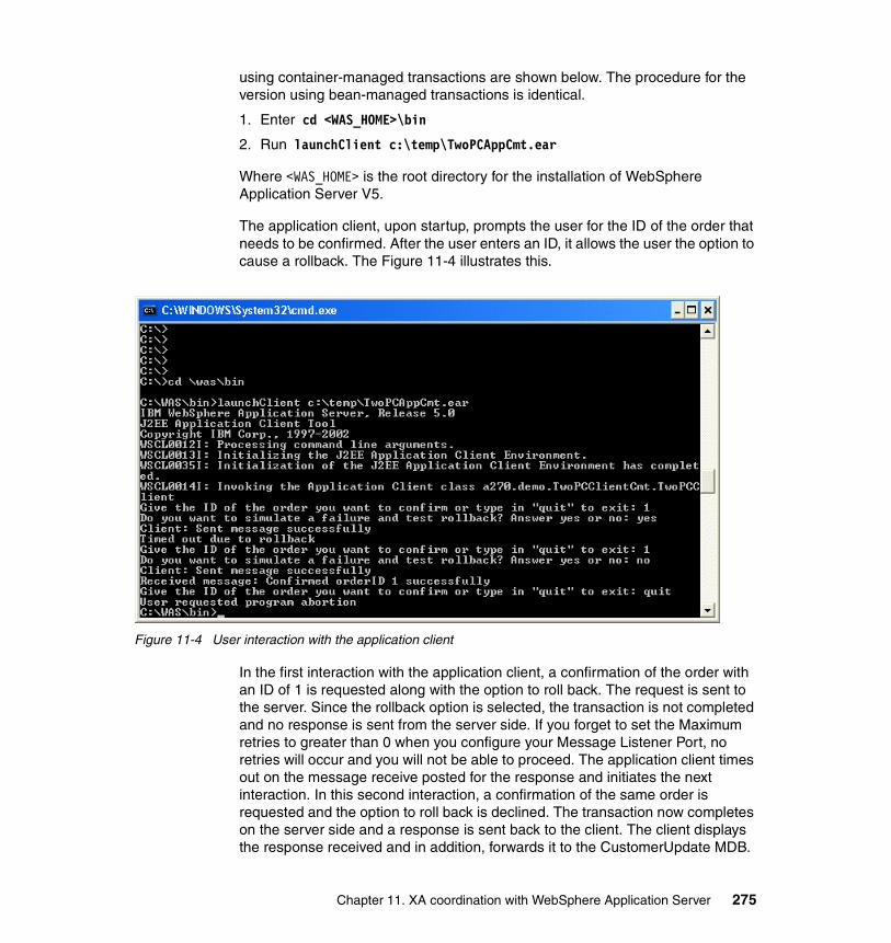
using container-managed transactions are shown below. The procedure for the version using bean-managed transactions is identical.
1. Enter cd <WAS_HOME>\bin
2. Run launchClient c:\temp\TwoPCAppCmt.ear
Where <WAS_HOME> is the root directory for the installation of WebSphere Application Server V5.
The application client, upon startup, prompts the user for the ID of the order that needs to be confirmed. After the user enters an ID, it allows the user the option to cause a rollback. The Figure 11-4 illustrates this.
Figure 11-4 User interaction with the application client
In the first interaction with the application client, a confirmation of the order with an ID of 1 is requested along with the option to roll back. The request is sent to the server. Since the rollback option is selected, the transaction is not completed and no response is sent from the server side. If you forget to set the Maximum retries to greater than 0 when you configure your Message Listener Port, no retries will occur and you will not be able to proceed. The application client times out on the message receive posted for the response and initiates the next interaction. In this second interaction, a confirmation of the same order is requested and the option to roll back is declined. The transaction now completes on the server side and a response is sent back to the client. The client displays the response received and in addition, forwards it to the CustomerUpdate MDB.
Chapter 11. XA coordination with WebSphere Application Server 275
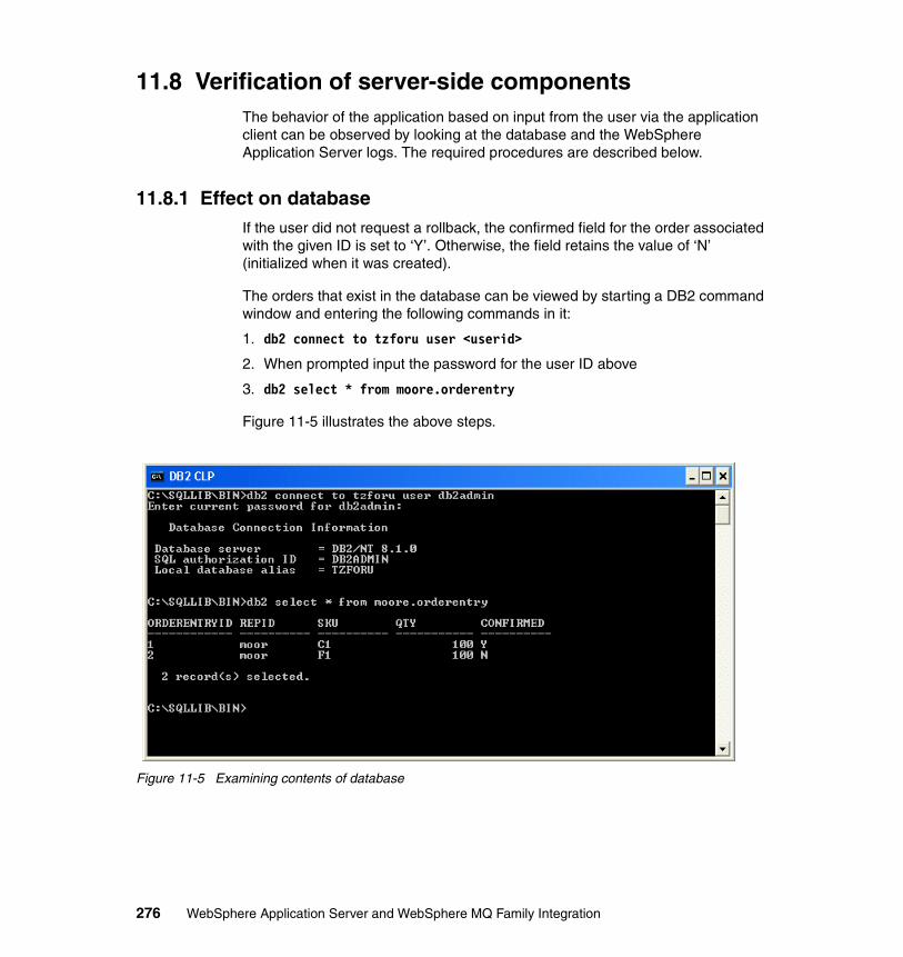
11.8 Verification of server-side componentsThe behavior of the application based on input from the user via the application client can be observed by looking at the database and the WebSphere Application Server logs. The required procedures are described below.
11.8.1 Effect on databaseIf the user did not request a rollback, the confirmed field for the order associated with the given ID is set to ‘Y’. Otherwise, the field retains the value of ‘N’ (initialized when it was created).
The orders that exist in the database can be viewed by starting a DB2 command window and entering the following commands in it:
1. db2 connect to tzforu user <userid>
2. When prompted input the password for the user ID above
3. db2 select * from moore.orderentry
Figure 11-5 illustrates the above steps.
Figure 11-5 Examining contents of database
276 WebSphere Application Server and WebSphere MQ Family Integration
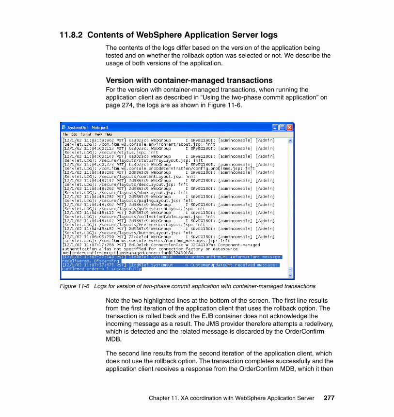
11.8.2 Contents of WebSphere Application Server logsThe contents of the logs differ based on the version of the application being tested and on whether the rollback option was selected or not. We describe the usage of both versions of the application.
Version with container-managed transactionsFor the version with container-managed transactions, when running the application client as described in “Using the two-phase commit application” on page 274, the logs are as shown in Figure 11-6.
Figure 11-6 Logs for version of two-phase commit application with container-managed transactions
Note the two highlighted lines at the bottom of the screen. The first line results from the first iteration of the application client that uses the rollback option. The transaction is rolled back and the EJB container does not acknowledge the incoming message as a result. The JMS provider therefore attempts a redelivery, which is detected and the related message is discarded by the OrderConfirm MDB.
The second line results from the second iteration of the application client, which does not use the rollback option. The transaction completes successfully and the application client receives a response from the OrderConfirm MDB, which it then
Chapter 11. XA coordination with WebSphere Application Server 277
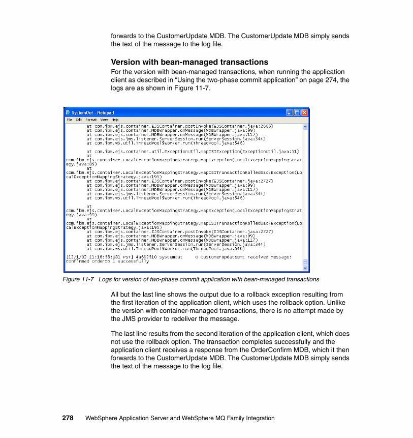
forwards to the CustomerUpdate MDB. The CustomerUpdate MDB simply sends the text of the message to the log file.
Version with bean-managed transactionsFor the version with bean-managed transactions, when running the application client as described in “Using the two-phase commit application” on page 274, the logs are as shown in Figure 11-7.
Figure 11-7 Logs for version of two-phase commit application with bean-managed transactions
All but the last line shows the output due to a rollback exception resulting from the first iteration of the application client, which uses the rollback option. Unlike the version with container-managed transactions, there is no attempt made by the JMS provider to redeliver the message.
The last line results from the second iteration of the application client, which does not use the rollback option. The transaction completes successfully and the application client receives a response from the OrderConfirm MDB, which it then forwards to the CustomerUpdate MDB. The CustomerUpdate MDB simply sends the text of the message to the log file.
278 WebSphere Application Server and WebSphere MQ Family Integration
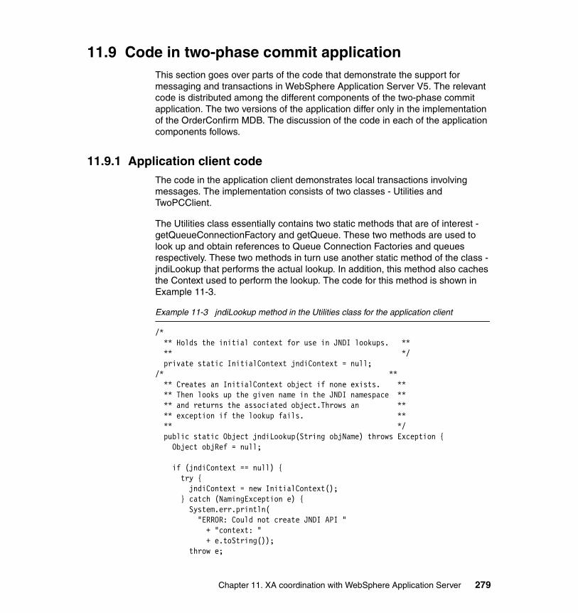
11.9 Code in two-phase commit applicationThis section goes over parts of the code that demonstrate the support for messaging and transactions in WebSphere Application Server V5. The relevant code is distributed among the different components of the two-phase commit application. The two versions of the application differ only in the implementation of the OrderConfirm MDB. The discussion of the code in each of the application components follows.
11.9.1 Application client codeThe code in the application client demonstrates local transactions involving messages. The implementation consists of two classes - Utilities and TwoPCClient.
The Utilities class essentially contains two static methods that are of interest - getQueueConnectionFactory and getQueue. These two methods are used to look up and obtain references to Queue Connection Factories and queues respectively. These two methods in turn use another static method of the class - jndiLookup that performs the actual lookup. In addition, this method also caches the Context used to perform the lookup. The code for this method is shown in Example 11-3.
Example 11-3 jndiLookup method in the Utilities class for the application client
/* ** Holds the initial context for use in JNDI lookups. ** ** */ private static InitialContext jndiContext = null;/* ** ** Creates an InitialContext object if none exists. ** ** Then looks up the given name in the JNDI namespace ** ** and returns the associated object.Throws an ** ** exception if the lookup fails. ** ** */ public static Object jndiLookup(String objName) throws Exception { Object objRef = null;
if (jndiContext == null) { try { jndiContext = new InitialContext(); } catch (NamingException e) { System.err.println( "ERROR: Could not create JNDI API " + "context: " + e.toString()); throw e;
Chapter 11. XA coordination with WebSphere Application Server 279
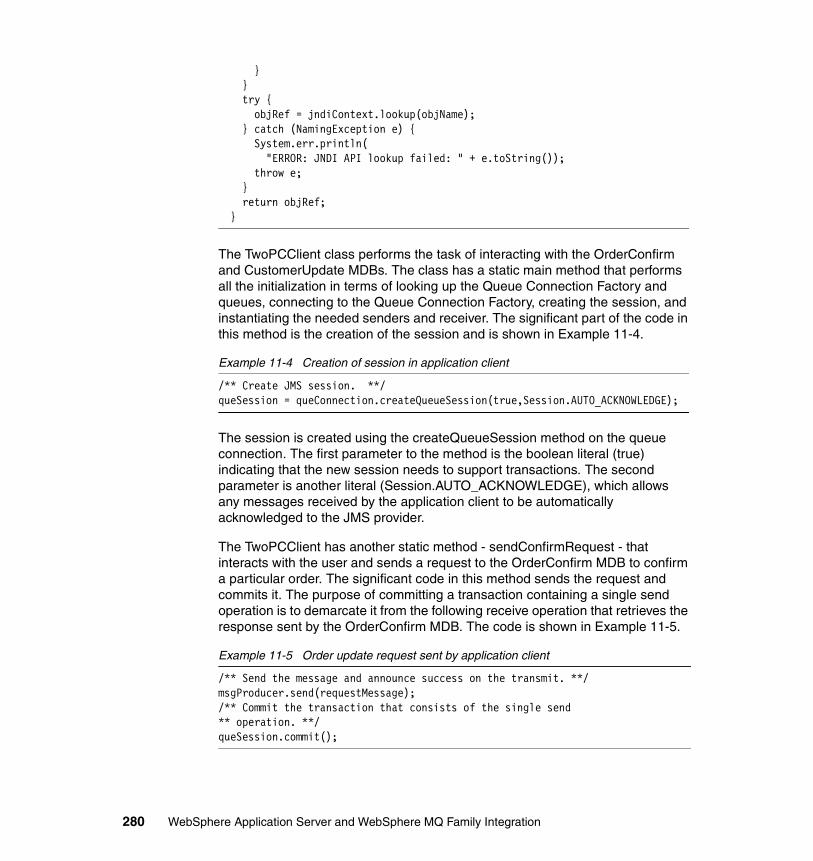
} } try { objRef = jndiContext.lookup(objName); } catch (NamingException e) { System.err.println( "ERROR: JNDI API lookup failed: " + e.toString()); throw e; } return objRef; }
The TwoPCClient class performs the task of interacting with the OrderConfirm and CustomerUpdate MDBs. The class has a static main method that performs all the initialization in terms of looking up the Queue Connection Factory and queues, connecting to the Queue Connection Factory, creating the session, and instantiating the needed senders and receiver. The significant part of the code in this method is the creation of the session and is shown in Example 11-4.
Example 11-4 Creation of session in application client
/** Create JMS session. **/queSession = queConnection.createQueueSession(true,Session.AUTO_ACKNOWLEDGE);
The session is created using the createQueueSession method on the queue connection. The first parameter to the method is the boolean literal (true) indicating that the new session needs to support transactions. The second parameter is another literal (Session.AUTO_ACKNOWLEDGE), which allows any messages received by the application client to be automatically acknowledged to the JMS provider.
The TwoPCClient has another static method - sendConfirmRequest - that interacts with the user and sends a request to the OrderConfirm MDB to confirm a particular order. The significant code in this method sends the request and commits it. The purpose of committing a transaction containing a single send operation is to demarcate it from the following receive operation that retrieves the response sent by the OrderConfirm MDB. The code is shown in Example 11-5.
Example 11-5 Order update request sent by application client
/** Send the message and announce success on the transmit. **/msgProducer.send(requestMessage);/** Commit the transaction that consists of the single send ** operation. **/queSession.commit();
280 WebSphere Application Server and WebSphere MQ Family Integration
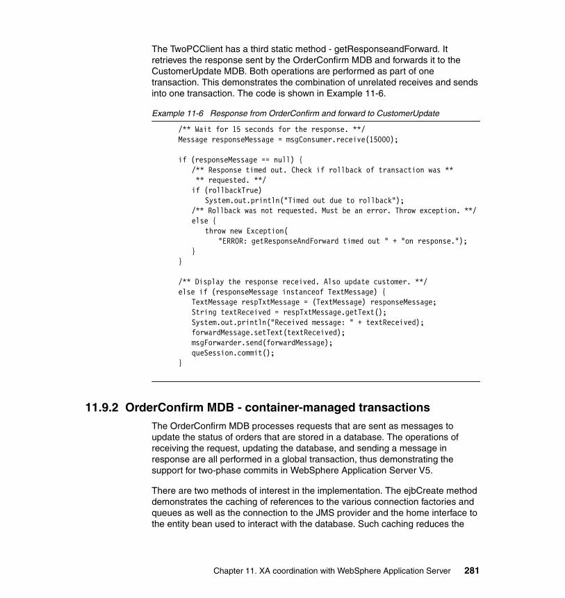
The TwoPCClient has a third static method - getResponseandForward. It retrieves the response sent by the OrderConfirm MDB and forwards it to the CustomerUpdate MDB. Both operations are performed as part of one transaction. This demonstrates the combination of unrelated receives and sends into one transaction. The code is shown in Example 11-6.
Example 11-6 Response from OrderConfirm and forward to CustomerUpdate
/** Wait for 15 seconds for the response. **/Message responseMessage = msgConsumer.receive(15000);
if (responseMessage == null) {/** Response timed out. Check if rollback of transaction was ** ** requested. **/if (rollbackTrue)
System.out.println("Timed out due to rollback");/** Rollback was not requested. Must be an error. Throw exception. **/else {
throw new Exception("ERROR: getResponseAndForward timed out " + "on response.");
}}
/** Display the response received. Also update customer. **/else if (responseMessage instanceof TextMessage) {
TextMessage respTxtMessage = (TextMessage) responseMessage;String textReceived = respTxtMessage.getText();System.out.println("Received message: " + textReceived);forwardMessage.setText(textReceived);msgForwarder.send(forwardMessage);queSession.commit();
}
11.9.2 OrderConfirm MDB - container-managed transactionsThe OrderConfirm MDB processes requests that are sent as messages to update the status of orders that are stored in a database. The operations of receiving the request, updating the database, and sending a message in response are all performed in a global transaction, thus demonstrating the support for two-phase commits in WebSphere Application Server V5.
There are two methods of interest in the implementation. The ejbCreate method demonstrates the caching of references to the various connection factories and queues as well as the connection to the JMS provider and the home interface to the entity bean used to interact with the database. Such caching reduces the
Chapter 11. XA coordination with WebSphere Application Server 281
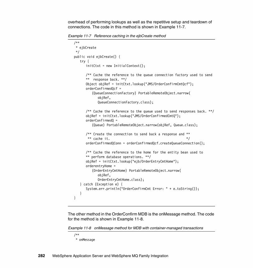
overhead of performing lookups as well as the repetitive setup and teardown of connections. The code in this method is shown in Example 11-7.
Example 11-7 Reference caching in the ejbCreate method
/** * ejbCreate */public void ejbCreate() {
try {initCtxt = new InitialContext();
/** Cache the reference to the queue connection factory used to send** response back. **/Object objRef = initCtxt.lookup("JMS/OrderConfirmCmtQcf");orderConfirmedQcf =
(QueueConnectionFactory) PortableRemoteObject.narrow(objRef,QueueConnectionFactory.class);
/** Cache the reference to the queue used to send responses back. **/objRef = initCtxt.lookup("JMS/OrderConfirmedCmtQ");orderConfirmedQ =
(Queue) PortableRemoteObject.narrow(objRef, Queue.class);
/** Create the connection to send back a response and ** ** cache it. */orderConfirmedQConn = orderConfirmedQcf.createQueueConnection();
/** Cache the reference to the home for the entity bean used to ** perform database operations. **/objRef = initCtxt.lookup("ejb/OrderEntryCmtHome");orderentryHome =
(OrderEntryCmtHome) PortableRemoteObject.narrow(objRef,OrderEntryCmtHome.class);
} catch (Exception e) {System.err.println("OrderConfirmCmt Error: " + e.toString());
}}
The other method in the OrderConfirm MDB is the onMessage method. The code for the method is shown in Example 11-8.
Example 11-8 onMessage method for MDB with container-managed transactions
/** * onMessage
282 WebSphere Application Server and WebSphere MQ Family Integration
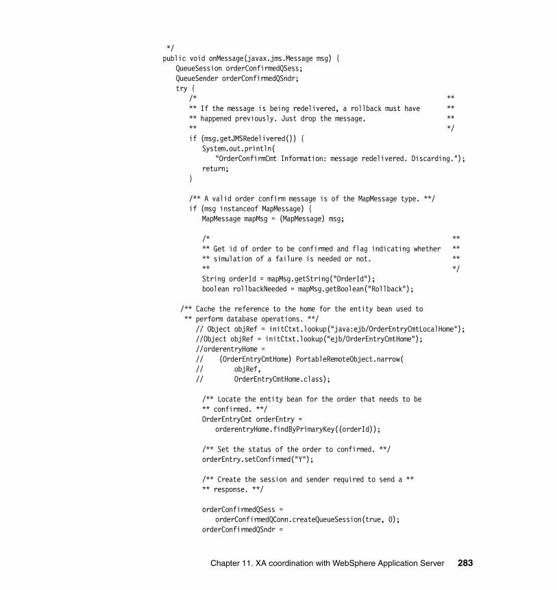
*/public void onMessage(javax.jms.Message msg) {
QueueSession orderConfirmedQSess;QueueSender orderConfirmedQSndr;try {
/* **** If the message is being redelivered, a rollback must have **** happened previously. Just drop the message. **** */if (msg.getJMSRedelivered()) {
System.out.println("OrderConfirmCmt Information: message redelivered. Discarding.");
return;}
/** A valid order confirm message is of the MapMessage type. **/if (msg instanceof MapMessage) {
MapMessage mapMsg = (MapMessage) msg;
/* **** Get id of order to be confirmed and flag indicating whether **** simulation of a failure is needed or not. **** */String orderId = mapMsg.getString("OrderId");boolean rollbackNeeded = mapMsg.getBoolean("Rollback");
/** Cache the reference to the home for the entity bean used to ** perform database operations. **/ // Object objRef = initCtxt.lookup("java:ejb/OrderEntryCmtLocalHome"); //Object objRef = initCtxt.lookup("ejb/OrderEntryCmtHome"); //orderentryHome = // (OrderEntryCmtHome) PortableRemoteObject.narrow( // objRef, // OrderEntryCmtHome.class);
/** Locate the entity bean for the order that needs to be** confirmed. **/OrderEntryCmt orderEntry =
orderentryHome.findByPrimaryKey((orderId));
/** Set the status of the order to confirmed. **/orderEntry.setConfirmed("Y");
/** Create the session and sender required to send a **** response. **/
orderConfirmedQSess =orderConfirmedQConn.createQueueSession(true, 0);
orderConfirmedQSndr =
Chapter 11. XA coordination with WebSphere Application Server 283
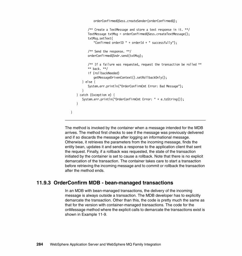
orderConfirmedQSess.createSender(orderConfirmedQ);
/** Create a TextMessage and store a text response in it. **/TextMessage txtMsg = orderConfirmedQSess.createTextMessage();txtMsg.setText(
"Confirmed orderID " + orderId + " successfully");
/** Send the response. **/orderConfirmedQSndr.send(txtMsg);
/** If a failure was requested, request the transaction be rolled **** back. **/if (rollbackNeeded)
getMessageDrivenContext().setRollbackOnly();} else {
System.err.println("OrderConfirmCmt Error: Bad Message");}
} catch (Exception e) {System.err.println("OrderConfirmCmt Error: " + e.toString());
}
}
The method is invoked by the container when a message intended for the MDB arrives. The method first checks to see if the message was previously delivered and if so discards the message after logging an informational message. Otherwise, it retrieves the parameters from the incoming message, finds the entity bean, updates it and sends a response to the application client that sent the request. Finally, if a rollback was requested, the state of the transaction initiated by the container is set to cause a rollback. Note that there is no explicit demarcation of the transaction. The container takes care to start a transaction before retrieving the incoming message and to commit or rollback the transaction after the method ends.
11.9.3 OrderConfirm MDB - bean-managed transactionsIn an MDB with bean-managed transactions, the delivery of the incoming message is always outside a transaction. The MDB developer has to explicitly demarcate the transaction. Other than this, the code is pretty much the same as that for the version with container-managed transactions. The code for the onMessage method where the explicit calls to demarcate the transactions exist is shown in Example 11-9.
284 WebSphere Application Server and WebSphere MQ Family Integration
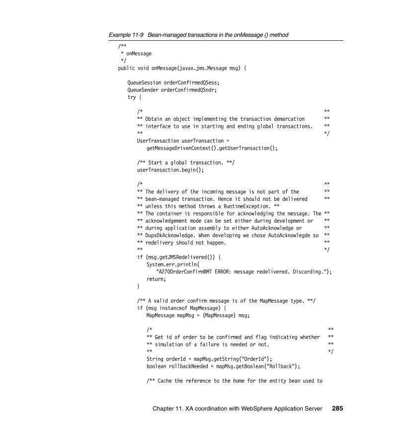
Example 11-9 Bean-managed transactions in the onMessage () method
/** * onMessage */public void onMessage(javax.jms.Message msg) {
QueueSession orderConfirmedQSess;QueueSender orderConfirmedQSndr;try {
/* **** Obtain an object implementing the transaction demarcation **** interface to use in starting and ending global transactions. **** */UserTransaction userTransaction =
getMessageDrivenContext().getUserTransaction();
/** Start a global transaction. **/userTransaction.begin();
/* **** The delivery of the incoming message is not part of the **** bean-managed transaction. Hence it should not be delivered **** unless this method throws a RuntimeException. **** The container is responsible for acknowledging the message. The **** acknowledgement mode can be set either during development or **** during application assembly to either AutoAcknowledge or **** DupsOkAcknowledge. When developing we chose AutoAcknowlegde so **** redelivery should not happen. **** */if (msg.getJMSRedelivered()) {
System.err.println("A270OrderConfirmBMT ERROR: message redelivered. Discarding.");
return;}
/** A valid order confirm message is of the MapMessage type. **/if (msg instanceof MapMessage) {
MapMessage mapMsg = (MapMessage) msg;
/* **** Get id of order to be confirmed and flag indicating whether **** simulation of a failure is needed or not. **** */String orderId = mapMsg.getString("OrderId");boolean rollbackNeeded = mapMsg.getBoolean("Rollback");
/** Cache the reference to the home for the entity bean used to
Chapter 11. XA coordination with WebSphere Application Server 285
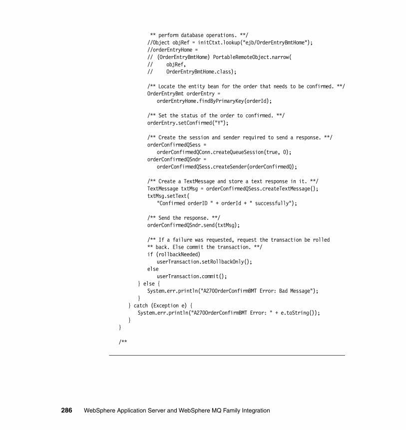
** perform database operations. **///Object objRef = initCtxt.lookup("ejb/OrderEntryBmtHome");//orderEntryHome =// (OrderEntryBmtHome) PortableRemoteObject.narrow(// objRef,// OrderEntryBmtHome.class);
/** Locate the entity bean for the order that needs to be confirmed. **/OrderEntryBmt orderEntry =
orderEntryHome.findByPrimaryKey(orderId);
/** Set the status of the order to confirmed. **/orderEntry.setConfirmed("Y");
/** Create the session and sender required to send a response. **/orderConfirmedQSess =
orderConfirmedQConn.createQueueSession(true, 0);orderConfirmedQSndr =
orderConfirmedQSess.createSender(orderConfirmedQ);
/** Create a TextMessage and store a text response in it. **/TextMessage txtMsg = orderConfirmedQSess.createTextMessage();txtMsg.setText(
"Confirmed orderID " + orderId + " successfully");
/** Send the response. **/orderConfirmedQSndr.send(txtMsg);
/** If a failure was requested, request the transaction be rolled** back. Else commit the transaction. **/if (rollbackNeeded)
userTransaction.setRollbackOnly();else
userTransaction.commit();} else {
System.err.println("A270OrderConfirmBMT Error: Bad Message");}
} catch (Exception e) {System.err.println("A270OrderConfirmBMT Error: " + e.toString());
}}
/**
286 WebSphere Application Server and WebSphere MQ Family Integration
11.10 SummaryThis chapter introduced transactions and went on to discuss local transactions in JMS. It presented support for JMS in WebSphere Application Server V5 and then discussed local and global transactions particularly in the context of WebSphere Application Server V5. Finally, it went into a detailed discussion of an application that demonstrates support for messaging and distributed transactions in WebSphere Application Server V5.
Chapter 11. XA coordination with WebSphere Application Server 287

288 WebSphere Application Server and WebSphere MQ Family Integration
Chapter 12. Setting up the WebSphere MQ environment
This chapter provides simple instructions on how to set up the WebSphere MQ V5.3.0.1 environment that we will use in later chapters to demonstrate the functions used in WebSphere MQ, WebSphere MQ Integrator Broker, and WebSphere MQ Event Broker to be included in a WebSphere Application Server V5 scenario.
The details for setup for the following specific products are included:
� WebSphere MQ V5.3.0.1
This will include the necessary setup to include an XA coordination example where WebSphere MQ is the two-phase commit coordinator.
� WebSphere MQ Integrator Broker V2.1 with CSD 3
This will include the necessary database setup for use with the product. In the scenarios later, instructions will be included to create a user database and tables.
� WebSphere MQ Event Broker V2.1
12
© Copyright IBM Corp. 2003. All rights reserved. 289
12.1 Deciding what must be in the environmentBased upon the scenario descriptions that we use in the JMS MQ Provider and Generic JMS Provider, we need to set up several products.
For the JMS MQ Provider scenario, we use:
� WebSphere MQ V5.3.0.1
This is the functional equivalent of WebSphere MQ V5.3 with CSD 1 but is a total product refresh.
� WebSphere MQ Integrator Broker V2.1 with CSD 3
We are using this product because we are not using any New Era of Networks functions or message formats. We could easily have used WebSphere MQ Integrator V2.1 (which does include the New Era of Networks function) since the remainder of the product is identical.
� WebSphere MQ Event Broker V2.1
� DB2 UDB V7.2 with Fix Pack 4
We will explain the setup for the broker databases here. This can also be used to create a user database when needed. The installation of DB2 UDB has already been explained earlier. If you need information on how to install it and the Fix Pack, refer to 7.1, “Installing DB2” on page 76.
Because we are setting up two separate systems, these need to be easily identified in the discussion. One system has WebSphere Application Server V5, WebSphere MQ V5.3.0.1, and WebSphere MQ Event Broker V2.1.
Since the WebSphere MQ Event Broker cannot reside on the same system as a WebSphere MQ Integrator Broker installation, we define a second machine environment to accommodate that. This second machine will represent the processing done for legacy preparation.
The first machine, where we run the browser and publish information using the WebSphere MQ Event Broker, will be called ITSOQ1. The second machine that hosts the WebSphere MQ Integrator Broker is called ITSOM1.
12.2 Defining the basic MQ environmentWe set up WebSphere MQ V5.3.0.1 first. The installation is identical on both of the machines.
290 WebSphere Application Server and WebSphere MQ Family Integration
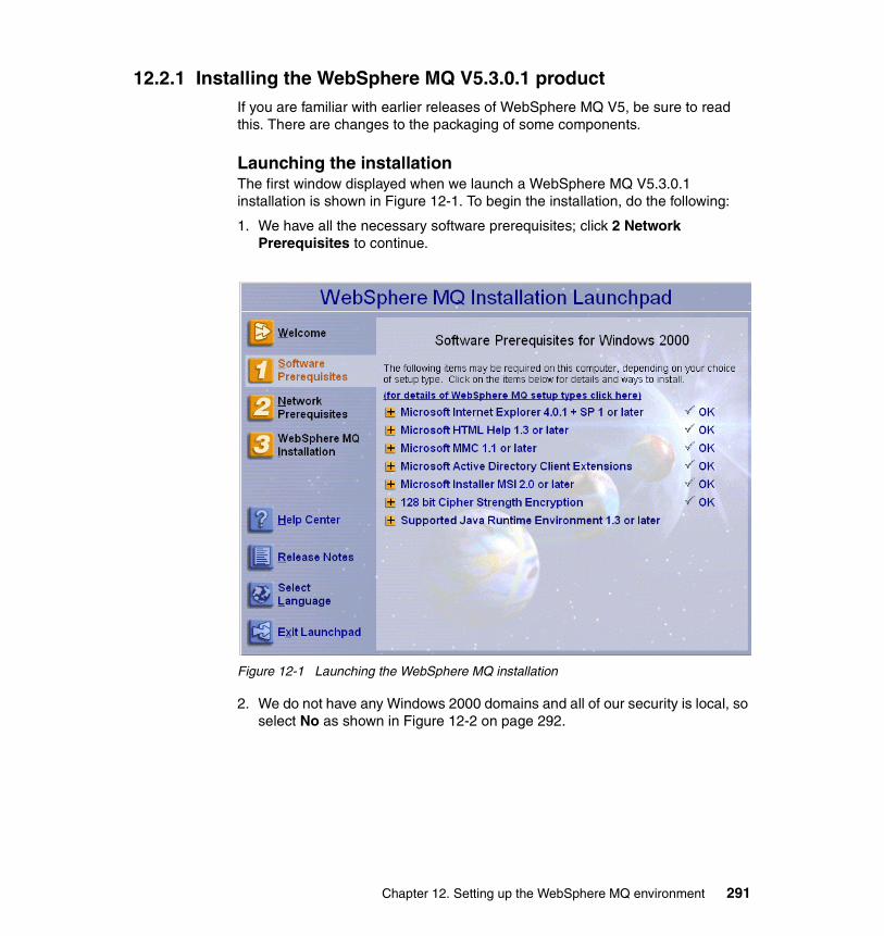
12.2.1 Installing the WebSphere MQ V5.3.0.1 productIf you are familiar with earlier releases of WebSphere MQ V5, be sure to read this. There are changes to the packaging of some components.
Launching the installationThe first window displayed when we launch a WebSphere MQ V5.3.0.1 installation is shown in Figure 12-1. To begin the installation, do the following:
1. We have all the necessary software prerequisites; click 2 Network Prerequisites to continue.
Figure 12-1 Launching the WebSphere MQ installation
2. We do not have any Windows 2000 domains and all of our security is local, so select No as shown in Figure 12-2 on page 292.
Chapter 12. Setting up the WebSphere MQ environment 291
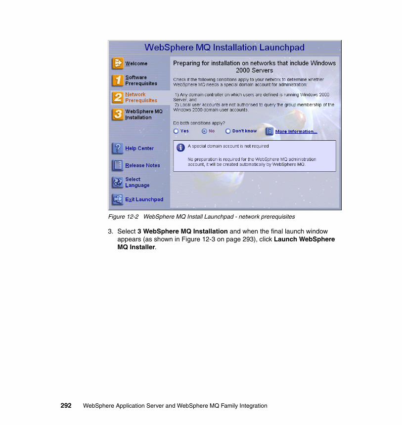
Figure 12-2 WebSphere MQ Install Launchpad - network prerequisites
3. Select 3 WebSphere MQ Installation and when the final launch window appears (as shown in Figure 12-3 on page 293), click Launch WebSphere MQ Installer.
292 WebSphere Application Server and WebSphere MQ Family Integration
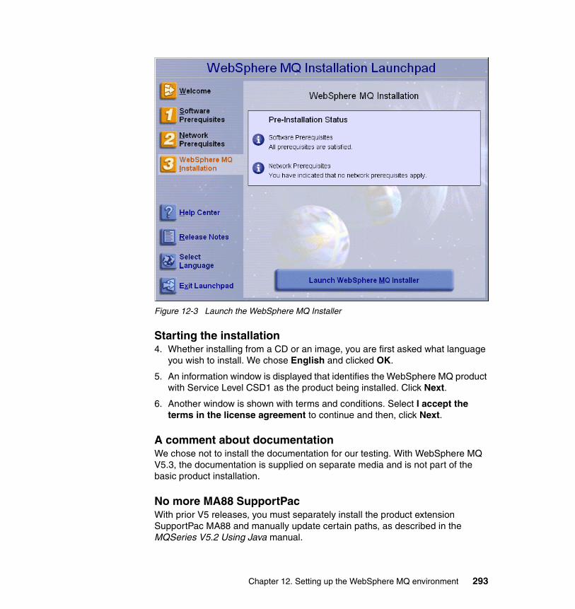
Figure 12-3 Launch the WebSphere MQ Installer
Starting the installation4. Whether installing from a CD or an image, you are first asked what language
you wish to install. We chose English and clicked OK.
5. An information window is displayed that identifies the WebSphere MQ product with Service Level CSD1 as the product being installed. Click Next.
6. Another window is shown with terms and conditions. Select I accept the terms in the license agreement to continue and then, click Next.
A comment about documentationWe chose not to install the documentation for our testing. With WebSphere MQ V5.3, the documentation is supplied on separate media and is not part of the basic product installation.
No more MA88 SupportPacWith prior V5 releases, you must separately install the product extension SupportPac MA88 and manually update certain paths, as described in the MQSeries V5.2 Using Java manual.
Chapter 12. Setting up the WebSphere MQ environment 293
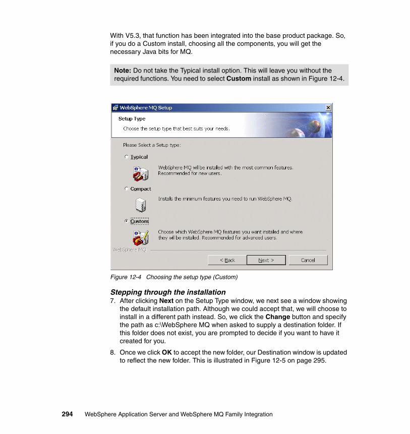
With V5.3, that function has been integrated into the base product package. So, if you do a Custom install, choosing all the components, you will get the necessary Java bits for MQ.
Figure 12-4 Choosing the setup type (Custom)
Stepping through the installation7. After clicking Next on the Setup Type window, we next see a window showing
the default installation path. Although we could accept that, we will choose to install in a different path instead. So, we click the Change button and specify the path as c:\WebSphere MQ when asked to supply a destination folder. If this folder does not exist, you are prompted to decide if you want to have it created for you.
8. Once we click OK to accept the new folder, our Destination window is updated to reflect the new folder. This is illustrated in Figure 12-5 on page 295.
Note: Do not take the Typical install option. This will leave you without the required functions. You need to select Custom install as shown in Figure 12-4.
294 WebSphere Application Server and WebSphere MQ Family Integration
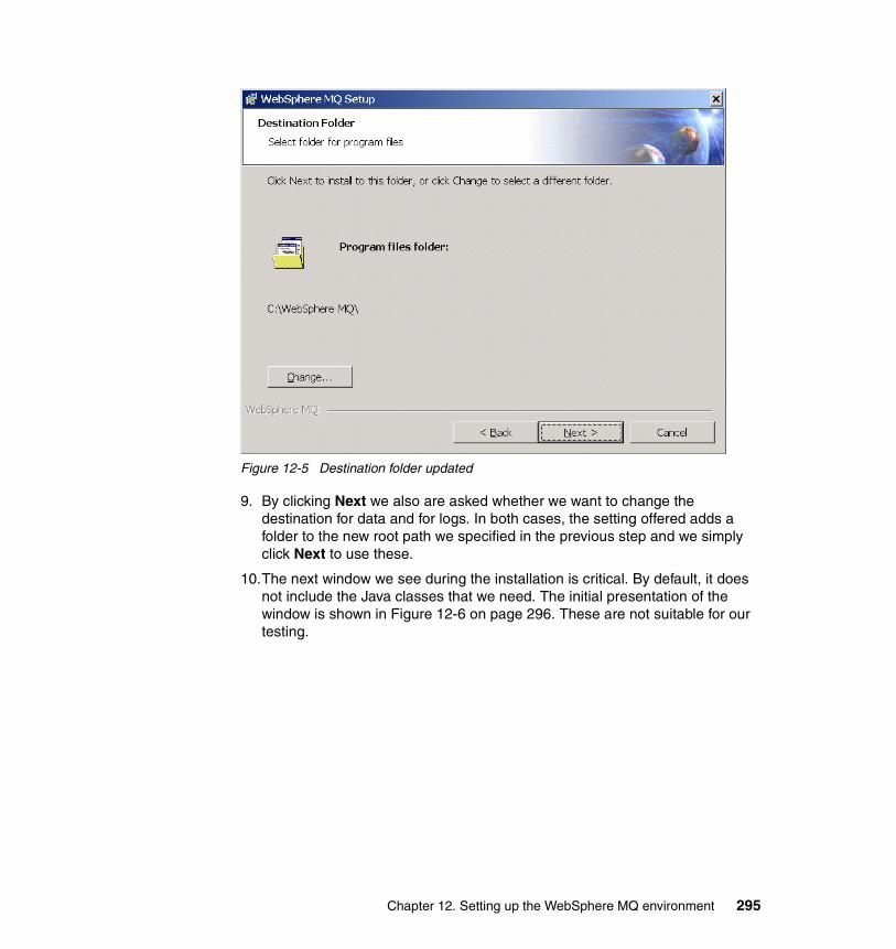
Figure 12-5 Destination folder updated
9. By clicking Next we also are asked whether we want to change the destination for data and for logs. In both cases, the setting offered adds a folder to the new root path we specified in the previous step and we simply click Next to use these.
10.The next window we see during the installation is critical. By default, it does not include the Java classes that we need. The initial presentation of the window is shown in Figure 12-6 on page 296. These are not suitable for our testing.
Chapter 12. Setting up the WebSphere MQ environment 295
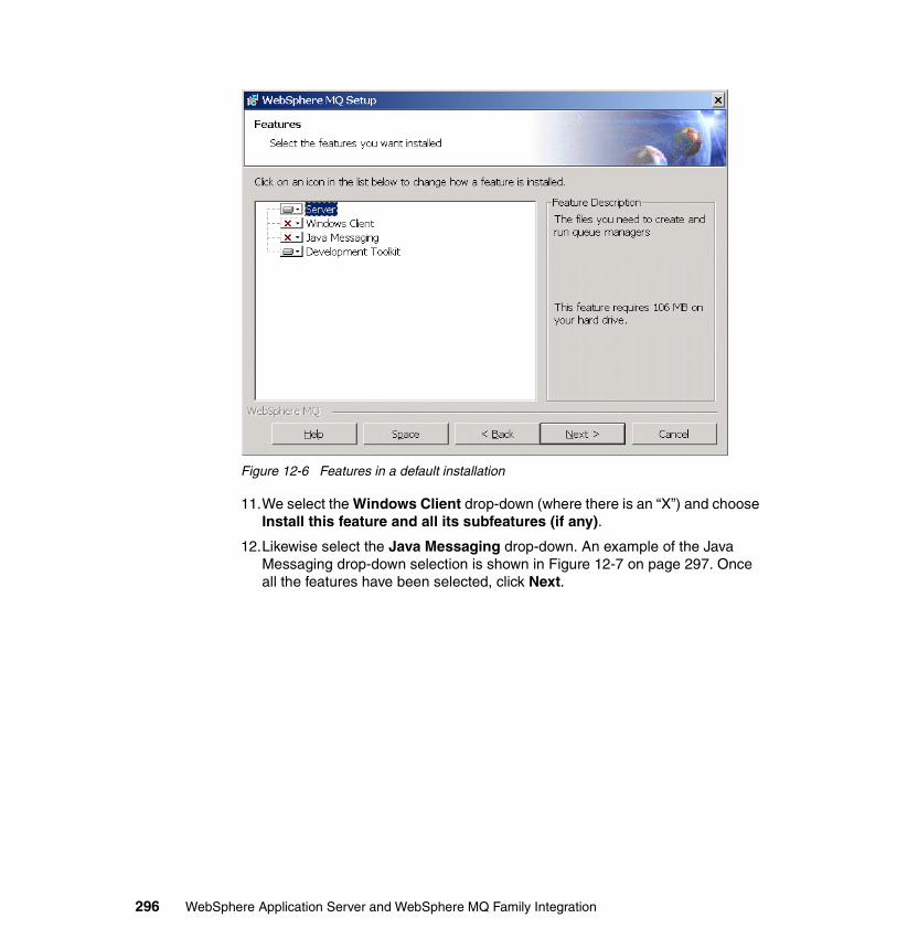
Figure 12-6 Features in a default installation
11.We select the Windows Client drop-down (where there is an “X”) and choose Install this feature and all its subfeatures (if any).
12.Likewise select the Java Messaging drop-down. An example of the Java Messaging drop-down selection is shown in Figure 12-7 on page 297. Once all the features have been selected, click Next.
296 WebSphere Application Server and WebSphere MQ Family Integration
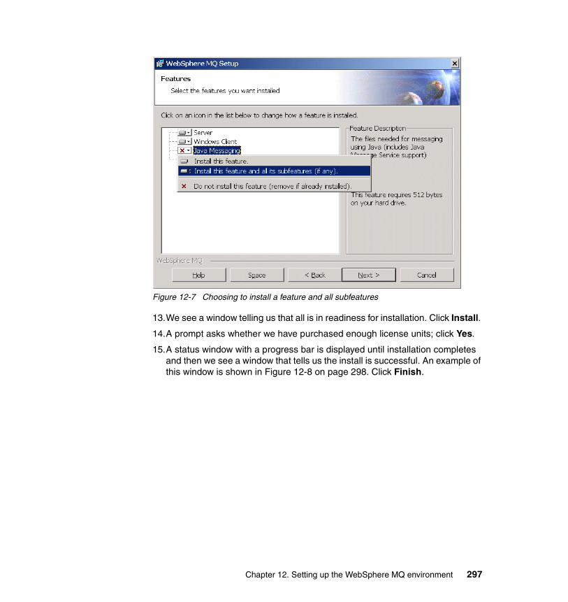
Figure 12-7 Choosing to install a feature and all subfeatures
13.We see a window telling us that all is in readiness for installation. Click Install.
14.A prompt asks whether we have purchased enough license units; click Yes.
15.A status window with a progress bar is displayed until installation completes and then we see a window that tells us the install is successful. An example of this window is shown in Figure 12-8 on page 298. Click Finish.
Chapter 12. Setting up the WebSphere MQ environment 297
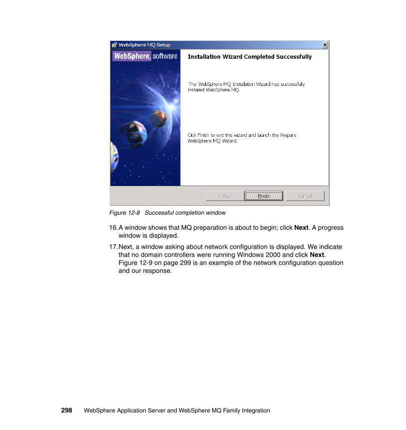
Figure 12-8 Successful completion window
16.A window shows that MQ preparation is about to begin; click Next. A progress window is displayed.
17.Next, a window asking about network configuration is displayed. We indicate that no domain controllers were running Windows 2000 and click Next. Figure 12-9 on page 299 is an example of the network configuration question and our response.
298 WebSphere Application Server and WebSphere MQ Family Integration
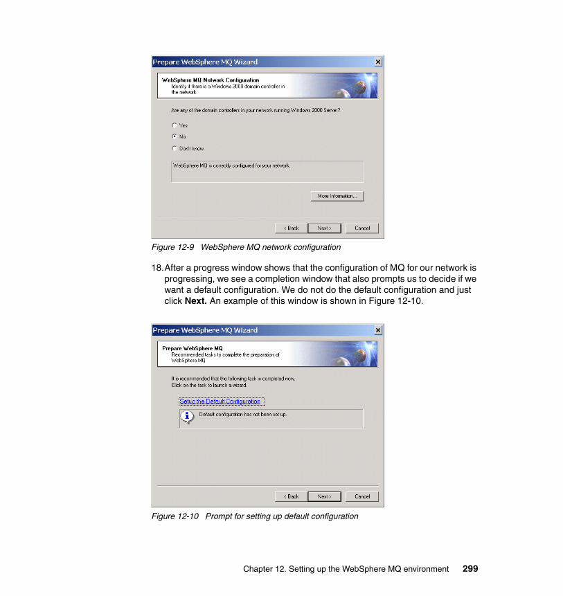
Figure 12-9 WebSphere MQ network configuration
18.After a progress window shows that the configuration of MQ for our network is progressing, we see a completion window that also prompts us to decide if we want a default configuration. We do not do the default configuration and just click Next. An example of this window is shown in Figure 12-10.
Figure 12-10 Prompt for setting up default configuration
Chapter 12. Setting up the WebSphere MQ environment 299
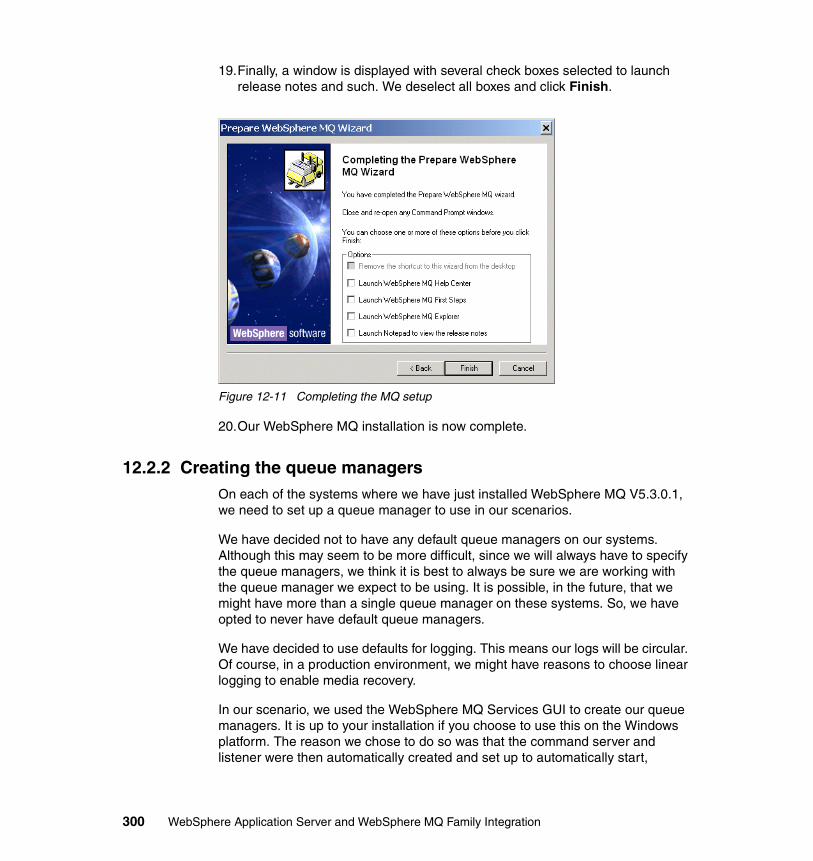
19.Finally, a window is displayed with several check boxes selected to launch release notes and such. We deselect all boxes and click Finish.
Figure 12-11 Completing the MQ setup
20.Our WebSphere MQ installation is now complete.
12.2.2 Creating the queue managersOn each of the systems where we have just installed WebSphere MQ V5.3.0.1, we need to set up a queue manager to use in our scenarios.
We have decided not to have any default queue managers on our systems. Although this may seem to be more difficult, since we will always have to specify the queue managers, we think it is best to always be sure we are working with the queue manager we expect to be using. It is possible, in the future, that we might have more than a single queue manager on these systems. So, we have opted to never have default queue managers.
We have decided to use defaults for logging. This means our logs will be circular. Of course, in a production environment, we might have reasons to choose linear logging to enable media recovery.
In our scenario, we used the WebSphere MQ Services GUI to create our queue managers. It is up to your installation if you choose to use this on the Windows platform. The reason we chose to do so was that the command server and listener were then automatically created and set up to automatically start,
300 WebSphere Application Server and WebSphere MQ Family Integration
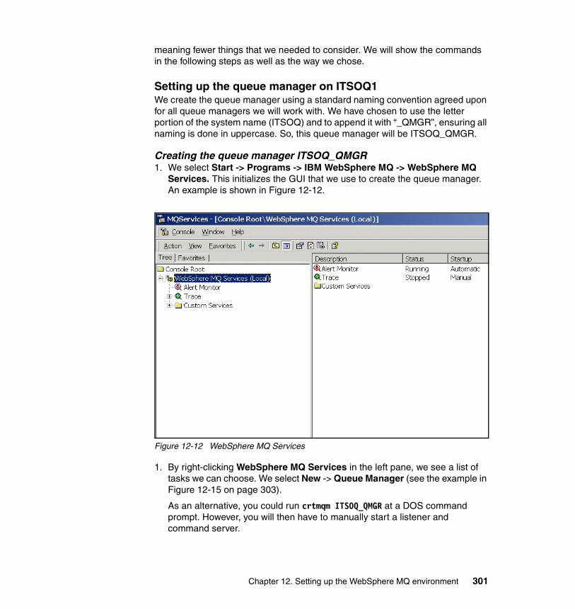
meaning fewer things that we needed to consider. We will show the commands in the following steps as well as the way we chose.
Setting up the queue manager on ITSOQ1We create the queue manager using a standard naming convention agreed upon for all queue managers we will work with. We have chosen to use the letter portion of the system name (ITSOQ) and to append it with “_QMGR”, ensuring all naming is done in uppercase. So, this queue manager will be ITSOQ_QMGR.
Creating the queue manager ITSOQ_QMGR1. We select Start -> Programs -> IBM WebSphere MQ -> WebSphere MQ
Services. This initializes the GUI that we use to create the queue manager. An example is shown in Figure 12-12.
Figure 12-12 WebSphere MQ Services
1. By right-clicking WebSphere MQ Services in the left pane, we see a list of tasks we can choose. We select New -> Queue Manager (see the example in Figure 12-15 on page 303).
As an alternative, you could run crtmqm ITSOQ_QMGR at a DOS command prompt. However, you will then have to manually start a listener and command server.
Chapter 12. Setting up the WebSphere MQ environment 301
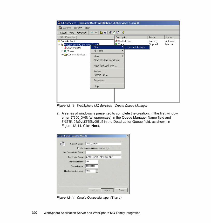
Figure 12-13 WebSphere MQ Services - Create Queue Manager
2. A series of windows is presented to complete the creation. In the first window, enter ITSOQ_QMGR (all uppercase) in the Queue Manager Name field and SYSTEM.DEAD.LETTER.QUEUE in the Dead Letter Queue field, as shown in Figure 12-14. Click Next.
Figure 12-14 Create Queue Manager (Step 1)
302 WebSphere Application Server and WebSphere MQ Family Integration
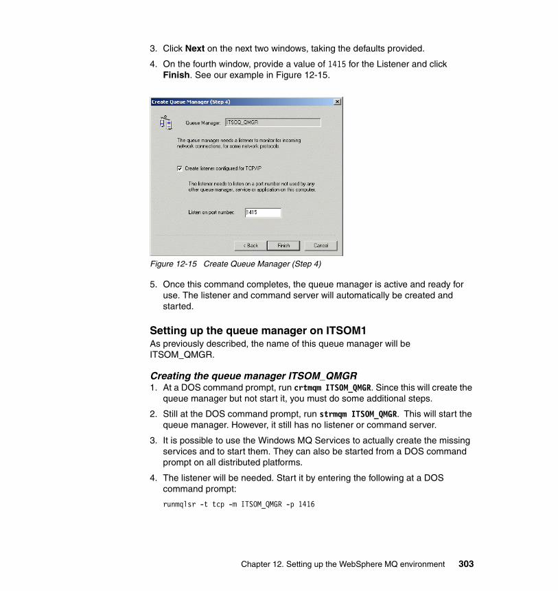
3. Click Next on the next two windows, taking the defaults provided.
4. On the fourth window, provide a value of 1415 for the Listener and click Finish. See our example in Figure 12-15.
Figure 12-15 Create Queue Manager (Step 4)
5. Once this command completes, the queue manager is active and ready for use. The listener and command server will automatically be created and started.
Setting up the queue manager on ITSOM1As previously described, the name of this queue manager will be ITSOM_QMGR.
Creating the queue manager ITSOM_QMGR1. At a DOS command prompt, run crtmqm ITSOM_QMGR. Since this will create the
queue manager but not start it, you must do some additional steps.
2. Still at the DOS command prompt, run strmqm ITSOM_QMGR. This will start the queue manager. However, it still has no listener or command server.
3. It is possible to use the Windows MQ Services to actually create the missing services and to start them. They can also be started from a DOS command prompt on all distributed platforms.
4. The listener will be needed. Start it by entering the following at a DOS command prompt:
runmqlsr -t tcp -m ITSOM_QMGR -p 1416
Chapter 12. Setting up the WebSphere MQ environment 303
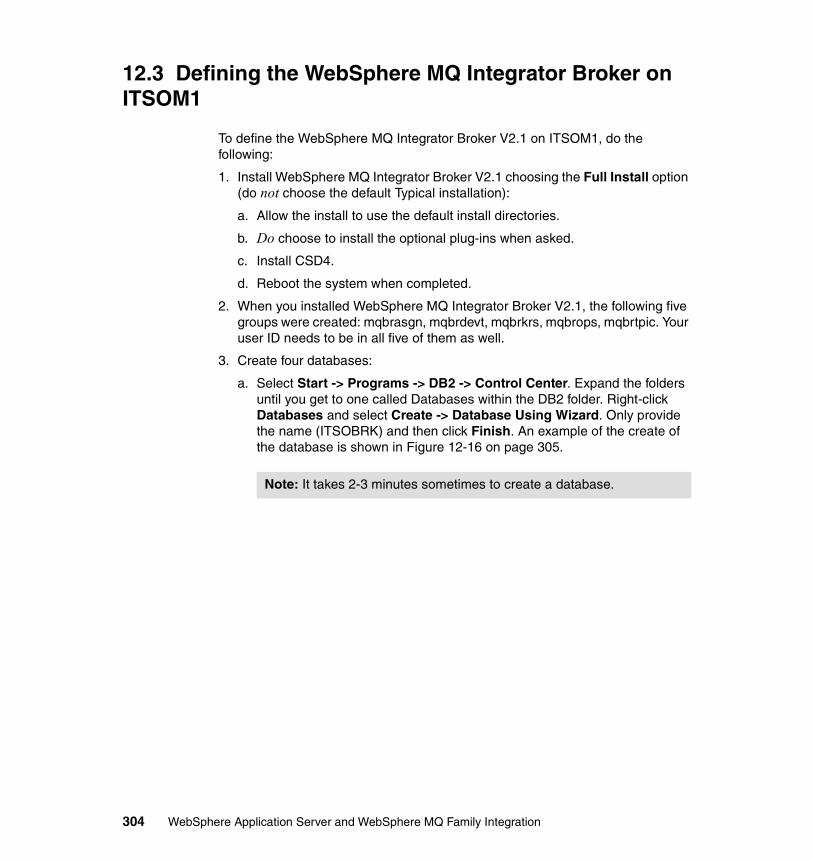
12.3 Defining the WebSphere MQ Integrator Broker on ITSOM1
To define the WebSphere MQ Integrator Broker V2.1 on ITSOM1, do the following:
1. Install WebSphere MQ Integrator Broker V2.1 choosing the Full Install option (do not choose the default Typical installation):
a. Allow the install to use the default install directories.
b. Do choose to install the optional plug-ins when asked.
c. Install CSD4.
d. Reboot the system when completed.
2. When you installed WebSphere MQ Integrator Broker V2.1, the following five groups were created: mqbrasgn, mqbrdevt, mqbrkrs, mqbrops, mqbrtpic. Your user ID needs to be in all five of them as well.
3. Create four databases:
a. Select Start -> Programs -> DB2 -> Control Center. Expand the folders until you get to one called Databases within the DB2 folder. Right-click Databases and select Create -> Database Using Wizard. Only provide the name (ITSOBRK) and then click Finish. An example of the create of the database is shown in Figure 12-16 on page 305.
Note: It takes 2-3 minutes sometimes to create a database.
304 WebSphere Application Server and WebSphere MQ Family Integration
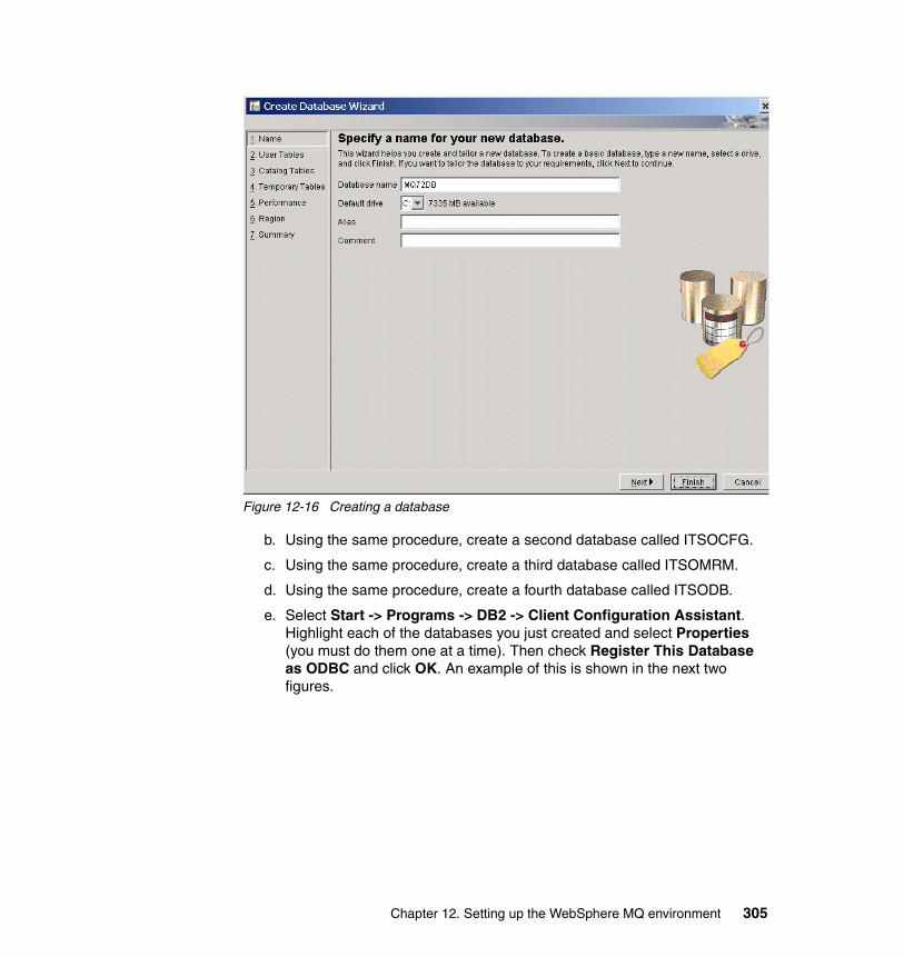
Figure 12-16 Creating a database
b. Using the same procedure, create a second database called ITSOCFG.
c. Using the same procedure, create a third database called ITSOMRM.
d. Using the same procedure, create a fourth database called ITSODB.
e. Select Start -> Programs -> DB2 -> Client Configuration Assistant. Highlight each of the databases you just created and select Properties (you must do them one at a time). Then check Register This Database as ODBC and click OK. An example of this is shown in the next two figures.
Chapter 12. Setting up the WebSphere MQ environment 305
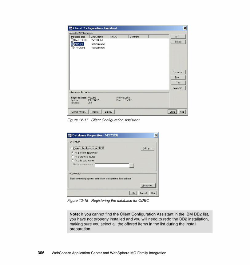
Figure 12-17 Client Configuration Assistant
Figure 12-18 Registering the database for ODBC
Note: If you cannot find the Client Configuration Assistant in the IBM DB2 list, you have not properly installed and you will need to redo the DB2 installation, making sure you select all the offered items in the list during the install preparation.
306 WebSphere Application Server and WebSphere MQ Family Integration
4. Make sure the queue managers have a dead letter queue identified as SYSTEM.DEAD.LETTER.QUEUE (uppercase) and that they have a TCP/IP listener defined using listener port 1414.
5. Select Programs -> WebSphere MQ Integrator Broker 2.1 -> Command Assistant -> Create Broker. When the interactive windows appear, complete them as follows:
a. Provide the broker name (ITSOM), the service user ID and service password (both db2admin - use lowercase), and the queue manager name (ITSOM_QMGR).
b. Provide a user name server queue manager name (ITSOM_QMGR).
c. Do not fill in the Workpath or LIL Path fields. Click Next>>.
d. Complete the fields Broker ODBC Data Source Name (ITSOBRK), the Broker Data Source User ID and Broker Data Source Password (both db2admin - lowercase). Do not choose MQSeries Fastpath Support and do not choose to migrate the MQSeries Publish/Subscribe broker. Click Next>>.
e. Click Finish. You will see a message indicating the broker is being created and eventually you will see a successful completion message. If not, you need to make sure that you have properly named the database to coincide with the one you created, that the database was set up to be an ODBC client, that the user ID is the one you were asked to use, and the password was entered using the proper case.
6. Select Programs -> WebSphere MQ Integrator Broker 2.1 -> Command Assistant -> Create Configuration Manager. When the interactive windows appear, complete them as follows:
a. Provide the service user ID and service password (both db2admin - use lowercase), the queue manager name (ITSOM_QMGR).
b. Provide a user name server queue manager name (ITSOM_QMGR).
c. Do not fill in Security Domain or Workpath. Click Next>>.
d. Complete the fields ConfigMgr Database Name (ITSOCFG), ConfigMgr Database User ID, ConfigMgr Database Password (both db2admin - lowercase), MRM ODBC Data Source Name (ITSOMRM), MRM Data Source User ID, and MRM Data Source Password (both db2admin - lowercase). Click Next>>.
e. Click Finish. You will see a message indicating the Configuration Manager is being created and eventually, you will see a successful completion message. If not, you need to make sure that you have properly named the databases to coincide with the ones you created, that the databases were both set up to be ODBC clients, that the user ID is the one you were asked to use, and the password was entered in the proper case.
Chapter 12. Setting up the WebSphere MQ environment 307
7. Select Programs -> WebSphere MQ Integrator Broker 2.1 -> Command Assistant -> Create User Name Server. When the interactive windows appear, complete them as follows:
f. Provide the service user ID and service password (both db2admin - use lowercase), the queue manager name (ITSOM_QMGR).
g. Click Next>>.
h. Click Finish. You will see a message indicating the user name server is being created and eventually you will see a successful completion message. If not, you need to make sure that the user ID is the one you were asked to use (and the password was entered in the proper case).
8. Select Start -> Settings -> Control Panel. Double-click Administrative Tools. Double-click Services.
a. In the list of services displayed in the Services window are three you need to change: IBM MQSeries Broker ITSOM, IBM MQSeries Broker User Name Server and IBM MQSeries Broker ConfigMgr.
b. Right-click the first one and choose Properties. In the Properties pane, you will see a Startup type about halfway down the pane. It is set to Manual. From the drop-down list, choose Automatic and then click the Start button. Once this is completed, click OK.
c. Do likewise for the other two services.
d. All three services should now indicate that they are started in the Services pane.
e. Close all the windows from this step.
9. Select Start -> Programs -> WebSphere MQ Integrator Broker 2.1 -> Control Center.
10.When the Configuration Manager Connection window is displayed, complete the Host Name field with localhost, Port with 1414 and the Queue Manager Name field with ITSOM_QMGR (uppercase). Click OK.
11.If the setup has completed successfully, you will see the Control Center open and provide you with the ability to work. If not, then you have done something incorrectly. Look at the MQ installation first; did you do a Custom installation and make sure all components were installed? Is the MQ Listener running (select Start -> Programs -> IBM WebSphere MQ -> WebSphere MQ Services; highlight the queue manager ITSOM_QMGR and look in the right pane to see if the Listener is active)? Did you make sure that the ConfigMgr Service was started?
12.Choose File -> Preferences. Expand the Control Center folder in the left pane of the resulting window that is displayed (called Control Center
308 WebSphere Application Server and WebSphere MQ Family Integration
Preferences). Select User’s Role and make sure the radio button called All roles is selected. Click OK.
13.Go to the Topology tab and right-click Topology in the left pane. Choose Check Out. A small box with a key will appear at the right of the Topology.
14.Again, right-click Topology in the left pane. Choose Create -> Broker. When the Create a New Broker window is displayed, complete the Name and Queue Manager fields (both need to be uppercase). Click Finish.
15.Select File -> Check In -> All (Save to Shared).
16.Once the box and key icon disappear from Topology, choose File -> Deploy -> Complete Configuration (all types) -> Normal. You will get a message stating that the deploy has started. It will take a few seconds to complete.
17.Go to the Log tab. Click the Refresh button (the button in the top toolbar that has green arrows going in a circle). You should see some informational messages. If you click these, they should indicate that pieces of the deploy worked. You should not see any messages other than those informational messages. If you do, check each message again and take the actions recommended.
18.Select File -> Exit. When prompted for a file name, use ITSOM and leave the extension as .xml. Do not change the folder where it is to be saved.
12.4 Defining the WebSphere MQ Event BrokerTo define the WebSphere MQ Event Broker, do the following:
1. Install WebSphere MQ Event Broker V2.1 choosing the Full Install option (do not choose the default Typical installation).
a. Allow the install to use the default install directories.
b. Do choose to install the optional plug-ins when asked.
c. There is no CSD.
d. Reboot the system when completed.
Note: If you click the Refresh button and nothing shows up, wait a little longer and try again; the deploy can sometimes take a little time since it is writing to DB2. If this deploy takes more than a minute, check the Windows Event Viewer to see what has been reported (look in both the Application and the System views).
Chapter 12. Setting up the WebSphere MQ environment 309
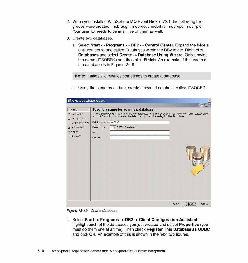
2. When you installed WebSphere MQ Event Broker V2.1, the following five groups were created: mqbrasgn, mqbrdevt, mqbrkrs, mqbrops, mqbrtpic. Your user ID needs to be in all five of them as well.
3. Create two databases.
a. Select Start -> Programs -> DB2 -> Control Center. Expand the folders until you get to one called Databases within the DB2 folder. Right-click Databases and select Create -> Database Using Wizard. Only provide the name (ITSOBRK) and then click Finish. An example of the create of the database is in Figure 12-19.
b. Using the same procedure, create a second database called ITSOCFG.
Figure 12-19 Create database
4. Select Start -> Programs -> DB2 -> Client Configuration Assistant; highlight each of the databases you just created and select Properties (you must do them one at a time). Then check Register This Database as ODBC and click OK. An example of this is shown in the next two figures.
Note: It takes 2-3 minutes sometimes to create a database.
310 WebSphere Application Server and WebSphere MQ Family Integration
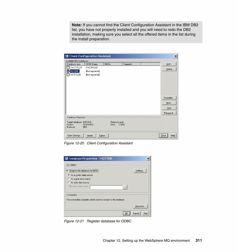
Figure 12-20 Client Configuration Assistant
Figure 12-21 Register database for ODBC
Note: If you cannot find the Client Configuration Assistant in the IBM DB2 list, you have not properly installed and you will need to redo the DB2 installation, making sure you select all the offered items in the list during the install preparation.
Chapter 12. Setting up the WebSphere MQ environment 311
5. Select Programs -> WebSphere MQ Event Broker 2.1 -> Command Assistant -> Create Broker. When the interactive windows appear, complete them as follows:
a. Provide the broker name (ITSOQ), the service user ID and service password (both db2admin - use lowercase), and the queue manager name (ITSOQ_QMGR).
b. Provide a user name server queue manager name (ITSOQ_QMGR).
c. Do not fill in the fields Workpath or LIL Path. Click Next>>.
d. Complete the fields Broker ODBC Data Source Name (ITSOBRK), Broker Data Source User ID, and Broker Data Source Password (both db2admin - lower case). Do not choose MQSeries Fastpath Support and do not choose to migrate the MQSeries Publish/Subscribe broker. Click Next>>.
e. Click Finish. You will see a message indicating the broker is being created and eventually, you will see a successful completion message. If not, you need to make sure that you have properly named the database to coincide with the one you created, that the database was set up to be an ODBC client, that the user ID is the one you were asked to use, and the password was entered using the proper case.
6. Select Programs -> WebSphere MQ Event Broker 2.1 -> Command Assistant -> Create Configuration Manager. When the interactive windows appear, complete them as follows:
a. Provide the service user ID and service password (both db2admin - use lower case), and the queue manager name (ITSOQ_QMGR).
b. Provide a user name server queue manager name (ITSOQ_QMGR).
c. Do not fill in Security Domain or Workpath. Click Next>>.
d. Complete the fields ConfigMgr Database Name (ITSOCFG), the ConfigMgr Database User ID, and ConfigMgr Database Password (both db2admin - lower case). Click Next>>.
e. Click Finish. You will see a message indicating the Configuration Manager is being created and eventually, you will see a successful completion message. If not, you need to make sure that you have properly named the databases to coincide with the ones you created, that the databases were both set up to be ODBC clients, that the user ID is the one you were asked to use, and the password was entered in the proper case.
7. Select Programs -> WebSphere MQ Event Broker 2.1 -> Command Assistant -> Create User Name Server. When the interactive windows appear, complete them as follows:
a. Provide the service user ID and service password (both db2admin - use lowercase), and the queue manager name (ITSOQ_QMGR).
312 WebSphere Application Server and WebSphere MQ Family Integration
b. Click Next>>.
c. Click Finish. You will see a message indicating the User Name Server is being created and eventually, you will see a successful completion message. If not, you need to make sure that the user ID is the one you were asked to use, and the password was entered in the proper case.
8. Select Start -> Settings -> Control Panel. Double-click Administrative Tools. Double-click Services.
a. In the list of services displayed in the Services window are three you need to change: IBM MQSeries Broker ITSOQ, IBM MQSeries Broker User Name Server, and IBM MQSeries Broker ConfigMgr.
b. Right-click the first one and choose Properties. In the Properties pane, you will see a Startup type about halfway down the pane. It is set to Manual. From the drop-down list, choose Automatic and then click the Start button. Once this is completed, click OK.
c. Do likewise for the other two services.
d. All three services should now indicate that they are Started in the Services pane.
e. Close all the windows from this step.
9. Select Start -> Programs -> WebSphere MQ Event Broker 2.1 -> Control Center.
10.When the Configuration Manager Connection window is displayed, complete the Host Name field with localhost, Port with 1414 and the Queue Manager Name field with ITSOQ_QMGR (uppercase). Click OK.
11.If the setup has completed successfully, you will see the Control Center open and provide you with the ability to work. If not, then you have done something incorrectly. Look at the MQ installation first; did you do a Custom installation and make sure all components were installed? Is the MQ Listener running (select Start -> Programs -> IBM WebSphere MQ -> WebSphere MQ Services; highlight the queue manager ITSOQ_QMGR and look in the right pane to see if the Listener is active)? Did you make sure that the ConfigMgr Service was started?
12.Choose File -> Preferences. Expand the Control Center folder in the left pane of the resulting window that is displayed (called Control Center Preferences). Select User’s Role and make sure the radio button called All roles is selected. Click OK.
13.Go to the Topology tab and right-click Topology in the left pane. Choose Check Out. A small box with a key will appear at the right of the Topology.
Chapter 12. Setting up the WebSphere MQ environment 313
14.Again, right-click Topology in the left pane. Choose Create -> Broker. When the Create a New Broker window is displayed, complete the Name and Queue Manager fields (both need to be upper case). Click Finish.
15.Select File -> Check In -> All (Save to Shared).
16.Once the box and key icon disappear from Topology, choose File -> Deploy -> Complete Configuration (all types) -> Normal. You will get a message stating that the deploy has started. It will take a few seconds to complete.
17.Go to the Log tab. Click the Refresh button (the button in the top toolbar that has green arrows going around). You should see some informational messages. If you click these, they should indicate that pieces of the deploy worked. You should not see any messages other than those informational messages. If you do, check each message again and take the actions recommended.
18.Select File -> Exit. When prompted for a file name, use ITSOQ and leave the extension as .xml. Do not change the folder where it is to be saved.
19.Setup is now complete.
Note: If you click the Refresh button and nothing shows up, wait a little longer and try again; the deploy can sometimes take a little time since it is writing to DB2. If this deploy takes more than a minute, check the Windows Event Viewer to see what has been reported (look in both the Application and the System views).
314 WebSphere Application Server and WebSphere MQ Family Integration
Chapter 13. WebSphere MQ Provider scenario
This scenario is designed to demonstrate the integration of WebSphere Application Server V5 with the WebSphere MQ family. We integrate WebSphere Application Server with WebSphere MQ V5.3.0.1, with the new WebSphere MQ Event Broker V2.1, and with WebSphere MQ Integrator Broker V2.1.
As well as demonstrating a way in which these products can be connected to each other, we also demonstrate one of the new features available in WebSphere Application Server V5: its ability to connect to a message queue via a JMS MQ Provider. We show how WebSphere MQ Event Broker can be used effectively within an enterprise and how WebSphere MQ Integrator Broker might be used when additional processing and database storage is required. Finally, we describe how distributed queuing through the use of clustering enables workload balancing and increases queue availability, enabling continuous operations.
13
© Copyright IBM Corp. 2003. All rights reserved. 315
13.1 Business case for this scenarioTZFORU Corporation has over 1200 employees spread across the United States. As most of the employees are accustomed to using the Web for their day to day activities, the Human Resources department wants to roll out a Web-based environment where each employee can update his or her personal details in regard to their employment status and benefits. The decision is to develop and implement this application from TZFORU’s IT department in California via WebSphere Application Server V5.
Currently, only the TZFORU Corporation offices in the states of New York, California and Texas are interested in this information. The Human Resources department expects other states to gradually want to be included and would like to implement a solution where states can be easily added on to the distribution. A decision is made to publish this information under a certain topic. As no processing of the information is required at this point, WebSphere MQ Event Broker is chosen to supply the publishing function. The messaging infrastructure to support these two products will be WebSphere MQ V5.3.
The TZFORU office in New York, California, and Texas want to subscribe to this information and update their own records within their local DB2 database. They would like to modify the records of their existing employees and add new records when they receive information on an employee for the first time. In addition to database updates, they may want to do some further processing of the message, so WebSphere MQ Integrator Broker V2.1 will be used to implement this solution.
A third-party payroll application will make use of the data within the message and update its own system. Its external interface requires the data to be in a generic XML format. WebSphere MQ Integrator Broker is able to transform the data within the message into XML and place that message on a queue for the third-party application to collect whenever it is run. Since this third-party application runs on its own system with its own local queue manager, TZFORU Corporation would also like to utilize WebSphere MQ distributed queuing functionality to get the message from the queue manager local to the WebSphere MQ Integrator Broker to the queue manager local to the third-party application.
The above scenario can be represented by the diagram shown in Figure 13-1.
Note: For demonstration purposes, we have replaced the third-party application with a Web application running within the WebSphere Application Server. By using a reply queue, we will be able to receive and display the final message on the screen. Three output queues, which represent each of the three states, will also be populated with the final message.
316 WebSphere Application Server and WebSphere MQ Family Integration
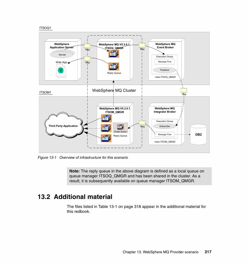
Figure 13-1 Overview of infrastructure for this scenario
13.2 Additional materialThe files listed in Table 13-1 on page 318 appear in the additional material for this redbook.
WebSphere MQ Cluster
ITSOQ1
ITSOM1
WebSphereApplication Server
WebSphere MQ V5.3.0.1ITSOQ_QMGR
WebSphere MQ V5.3.0.1ITSOM_QMGR
WebSphere MQEvent Broker
WebSphere MQIntegrator Broker
Msg Msg
DB2
Execution Group
Message Flow
Publisher
Execution Group
Message Flow
Subscriber
Msg
MsgWeb App
Uses ITSOQ_QMGR
Uses ITSOM_QMGR
Servlet
Third Party Application Msg
Reply Queue
Reply Queue
Cluster Queue
Note: The reply queue in the above diagram is defined as a local queue on queue manager ITSOQ_QMGR and has been shared in the cluster. As a result, it is subsequently available on queue manager ITSOM_QMGR.
Chapter 13. WebSphere MQ Provider scenario 317
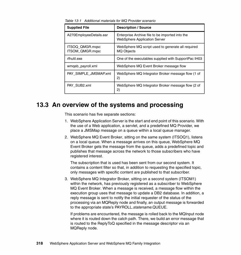
Table 13-1 Additional materials for MQ Provider scenario
13.3 An overview of the systems and processingThis scenario has five separate sections:
1. WebSphere Application Server is the start and end point of this scenario. With the use of a Web application, a servlet, and a predefined MQ Provider, we place a JMSMap message on a queue within a local queue manager.
2. WebSphere MQ Event Broker, sitting on the same system (ITSOQ1), listens on a local queue. When a message arrives on this queue, WebSphere MQ Event Broker gets the message from the queue, adds a predefined topic and publishes that message across the network to those subscribers who have registered interest.
The subscription that is used has been sent from our second system. It contains a content filter so that, in addition to requesting the specified topic, only messages with specific content are published to that subscriber.
3. WebSphere MQ Integrator Broker, sitting on a second system (ITSOM1) within the network, has previously registered as a subscriber to WebSphere MQ Event Broker. When a message is received, a message flow within the execution group uses that message to update a DB2 database. In addition, a reply message is sent to notify the initial requester of the status of the processing via an MQReply node and finally, an output message is forwarded to the appropriate state’s PAYROLL.statename.QUEUE.
If problems are encountered, the message is rolled back to the MQInput node where it is routed down the catch path. There, we build an error message that is routed to the ReplyToQ specified in the message descriptor via an MQReply node.
Supplied File Description / Source
A270EmployeeDetails.ear Enterprise Archive file to be imported into the WebSphere Application Server
ITSOQ_QMGR.mqscITSOM_QMGR.mqsc
WebSphere MQ script used to generate all required MQ Objects
rfhutil.exe One of the executables supplied with SupportPac IH03
wmqeb_payroll.xml WebSphere MQ Event Broker message flow
PAY_SIMPLE_JMSMAP.xml WebSphere MQ Integrator Broker message flow (1 of 2)
PAY_SUB2.xml WebSphere MQ Integrator Broker message flow (2 of 2)
318 WebSphere Application Server and WebSphere MQ Family Integration
If that path fails, we simply route the message to a local queue called PAYROLL.EXCEPTION. In a full solution, we would implement an error routine to handle those exception messages.
4. The two queue managers, both on separate systems, are defined as belonging to the same cluster. As a result, the three local queues within the second queue manager, are also available to the first queue manager through the use of the cluster definition for PUTting messages. As with base MQ, it is not possible to GET messages from a remote queue, even when these are queues known in an MQ cluster.
Because we have an MQ cluster set up, we do not have to define any additional channels, remote queues or additional transmission queues; the cluster environment will be able to carry all messages between these two queue managers.
5. The initial Web application running within the WebSphere Application Server is used to get the reply message from the reply queue. Finally, the contents of the reply message is displayed within the browser window.
13.4 WebSphere MQ configuration on both systemsHere, we implement the WebSphere MQ infrastructure covering both platforms.
As mentioned briefly above, we decided to implement MQ clustering in order to show some of the benefits of this technology within our environment.
13.4.1 Setting up the WebSphere MQ infrastructure on ITSOQ1Our first system is called ITSOQ1. On ITSOQ1 we defined a number of WebSphere MQ objects including a queue onto which the servlet running in WebSphere Application Server will put a message. Figure 13-1 on page 317 shows that WebSphere MQ Integrator Broker is also installed on the second system (ITSOM1).
We use a script file and line commands for defining these resources, because the WebSphere MQ Explorer is occasionally inconsistent when displaying the
Note: We assume that WebSphere MQ Version 5.3.0.1 is already installed correctly on both of the two systems shown in Figure 13-1 on page 317. We also assume that WebSphere MQ Event Broker is correctly installed on one system and WebSphere MQ Integrator Broker on the other system. Refer to Chapter 12, “Setting up the WebSphere MQ environment” on page 289 for further details.
Chapter 13. WebSphere MQ Provider scenario 319
contents of objects in a clustered environment. In addition, the script file can be used to define the required resources on other WebSphere MQ platforms. The following procedure sets up the WebSphere MQ environment on ITSOQ1:
1. From a command line prompt, create a queue manager by entering:
crtmqm ITSOQ_QMGR
2. Start the queue manager by entering:
strmqm ITSOQ_QMGR
3. Run a script to define or modify the objects required for ITSOQ_QMGR on ITSOQ1 by entering:
runmqsc ITSOQ_QMGR < itsoq_qmgr.mqsc
The itsoq_qmgr.mqsc script file is reproduced in full in Appendix B, “WebSphere MQ Provider scenario” on page 415.
4. Start the MQ listener by entering:
runmqlsr -m ITSOQ_QMGR -t TCP -p 1415
5. Do not close the command window (you may minimize it). If you start the listener by prefixing this command with start, the listener will start as a separate process without leaving a command window open:
start runmqlsr -m ITSOQ_QMGR -t TCP -p 1415.
6. Import a message flow for WebSphere MQ Event Broker, for more information refer to 13.6, “Configuring WebSphere MQ Event Broker on ITSOQ1” on page 334.
13.4.2 Setting up the WebSphere MQ infrastructure on ITSOM1Our second system is called ITSOM1. On ITSOM1 we define a number of WebSphere MQ objects including three queues used for output from a message flow that will run in WebSphere MQ Integrator Broker. Figure 13-1 on page 317 shows that WebSphere MQ Integrator Broker is also installed on ITSOM1.
We use a script file and line commands for defining these resources, because the WebSphere MQ Explorer is occasionally inconsistent when displaying the contents of objects in a clustered environment. In addition, the script file can be used to define the required resources on other WebSphere MQ platforms. The following procedure sets up the WebSphere MQ environment on ITSOM1:
1. From a command line prompt, create a queue manager by entering:
crtmqm ITSOM_QMGR
Note: We do not use any default queue managers.
320 WebSphere Application Server and WebSphere MQ Family Integration
2. Start the queue manager by entering:
strmqm ITSOM_QMGR
3. Run a script to define or modify the objects required for system one by entering:
runmqsc ITSOM_QMGR < itsom_qmgr.mqsc
The itsom_qmgr.mqsc script file is reproduced in full in Appendix B, “WebSphere MQ Provider scenario” on page 415.
4. Start the MQ listener by entering:
runmqlsr -m ITSOM_QMGR -t TCP -p 1415
5. Do not close the command window (you may minimize it). If you start the listener by prefixing this command with start, the listener will start as a separate process without leaving a command window open:
start runmqlsr -m ITSOM_QMGR -t TCP -p 1415
6. Import a message flow for WebSphere MQ Integrator Broker. (See 12.3, “Defining the WebSphere MQ Integrator Broker on ITSOM1” on page 304).
After we execute these steps, we have an environment with two queue managers, each of which has the necessary objects defined to demonstrate the scenario described at the beginning of this chapter. The two queue managers are part of a cluster called ITSO_CLUSTER and are both full repository queue managers. The queues defined to ITSOM1 are defined as being part of this cluster and can therefore be accessed by an application running on ITSOQ1.
Figure 13-2 on page 322 shows what our WebSphere MQ infrastructure looks like after completing the two sets of instructions just discussed. (We also have WebSphere MQ Event Broker set up on ITSOQ1 and WebSphere MQ Integrator Broker set up on ITSOM1.)
Chapter 13. WebSphere MQ Provider scenario 321
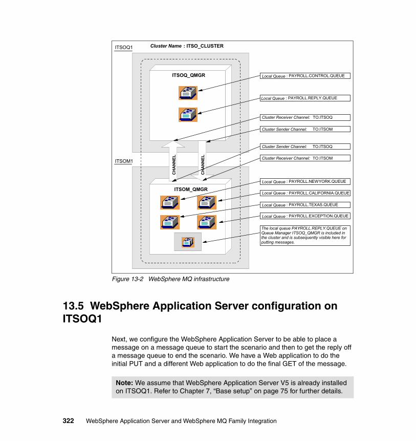
Figure 13-2 WebSphere MQ infrastructure
13.5 WebSphere Application Server configuration on ITSOQ1
Next, we configure the WebSphere Application Server to be able to place a message on a message queue to start the scenario and then to get the reply off a message queue to end the scenario. We have a Web application to do the initial PUT and a different Web application to do the final GET of the message.
ITSOQ1
ITSOM1
ITSOQ_QMGR
ITSOM_QMGR
Cluster Name : ITSO_CLUSTER
CHA
NNEL
CHA
NNEL
Local Queue : PAYROLL.NEWYORK.QUEUE
Local Queue : PAYROLL.TEXAS.QUEUE
Local Queue : PAYROLL.CALIFORNIA.QUEUE
Local Queue : PAYROLL.REPLY.QUEUE
Cluster Receiver Channel: TO.ITSOQ
Local Queue : PAYROLL.EXCEPTION.QUEUE
Cluster Sender Channel: TO.ITSOM
Cluster Receiver Channel: TO.ITSOM
Cluster Sender Channel: TO.ITSOQ
The local queue PAYROLL.REPLY.QUEUE on Queue Manager ITSOQ_QMGR is included in the cluster and is subsequently visible here for putting messages.
Local Queue : PAYROLL.CONTROL.QUEUE
Note: We assume that WebSphere Application Server V5 is already installed on ITSOQ1. Refer to Chapter 7, “Base setup” on page 75 for further details.
322 WebSphere Application Server and WebSphere MQ Family Integration
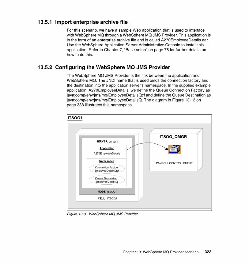
13.5.1 Import enterprise archive fileFor this scenario, we have a sample Web application that is used to interface with WebSphere MQ through a WebSphere MQ JMS Provider. This application is in the form of an enterprise archive file and is called A270EmployeeDetails.ear. Use the WebSphere Application Server Administrative Console to install this application. Refer to Chapter 7, “Base setup” on page 75 for further details on how to do this.
13.5.2 Configuring the WebSphere MQ JMS ProviderThe WebSphere MQ JMS Provider is the link between the application and WebSphere MQ. The JNDI name that is used binds the connection factory and the destination into the application server's namespace. In the supplied example application, A270EmployeeDetails, we define the Queue Connection Factory as java:comp/env/jms/mq/EmployeeDetailsQcf and define the Queue Destination as java:comp/env/jms/mq/EmployeeDetailsQ. The diagram in Figure 13-13 on page 338 illustrates this namespace.
Figure 13-3 WebSphere MQ JMS Provider
ITSOQ1
ITSOQ_QMGR
NODE: ITSOQ1
CELL: ITSOQ1
SERVER: server1
Application
A270EmployeeDetails
Namespace
Connection FactoryEmployeeDetailsQcf
Queue DestinationEmployeeDetailsQ
PAYROLL.CONTROL.QUEUE
Chapter 13. WebSphere MQ Provider scenario 323
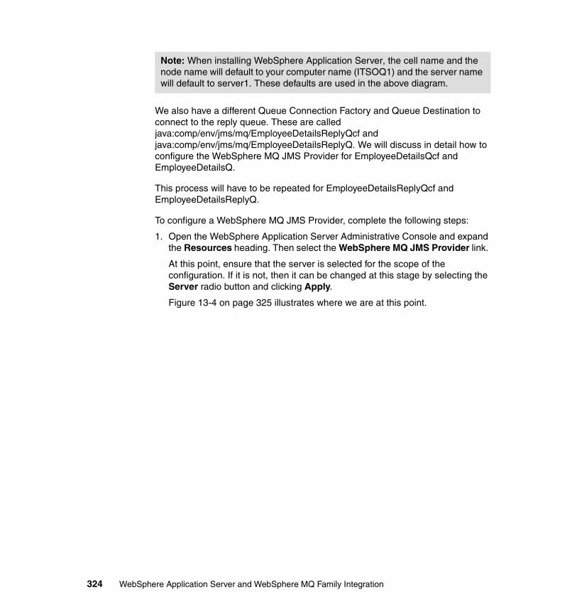
We also have a different Queue Connection Factory and Queue Destination to connect to the reply queue. These are called java:comp/env/jms/mq/EmployeeDetailsReplyQcf and java:comp/env/jms/mq/EmployeeDetailsReplyQ. We will discuss in detail how to configure the WebSphere MQ JMS Provider for EmployeeDetailsQcf and EmployeeDetailsQ.
This process will have to be repeated for EmployeeDetailsReplyQcf and EmployeeDetailsReplyQ.
To configure a WebSphere MQ JMS Provider, complete the following steps:
1. Open the WebSphere Application Server Administrative Console and expand the Resources heading. Then select the WebSphere MQ JMS Provider link.
At this point, ensure that the server is selected for the scope of the configuration. If it is not, then it can be changed at this stage by selecting the Server radio button and clicking Apply.
Figure 13-4 on page 325 illustrates where we are at this point.
Note: When installing WebSphere Application Server, the cell name and the node name will default to your computer name (ITSOQ1) and the server name will default to server1. These defaults are used in the above diagram.
324 WebSphere Application Server and WebSphere MQ Family Integration
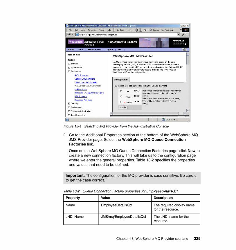
Figure 13-4 Selecting MQ Provider from the Administrative Console
2. Go to the Additional Properties section at the bottom of the WebSphere MQ JMS Provider page. Select the WebSphere MQ Queue Connection Factories link.
Once on the WebSphere MQ Queue Connection Factories page, click New to create a new connection factory. This will take us to the configuration page where we enter the general properties. Table 13-2 specifies the properties and values that need to be defined.
Table 13-2 Queue Connection Factory properties for EmployeeDetailsQcf
Important: The configuration for the MQ provider is case sensitive. Be careful to get the case correct.
Property Value Description
Name EmployeeDetailsQcf The required display name for the resource.
JNDI Name JMS/mq/EmployeeDetailsQcf The JNDI name for the resource.
Chapter 13. WebSphere MQ Provider scenario 325
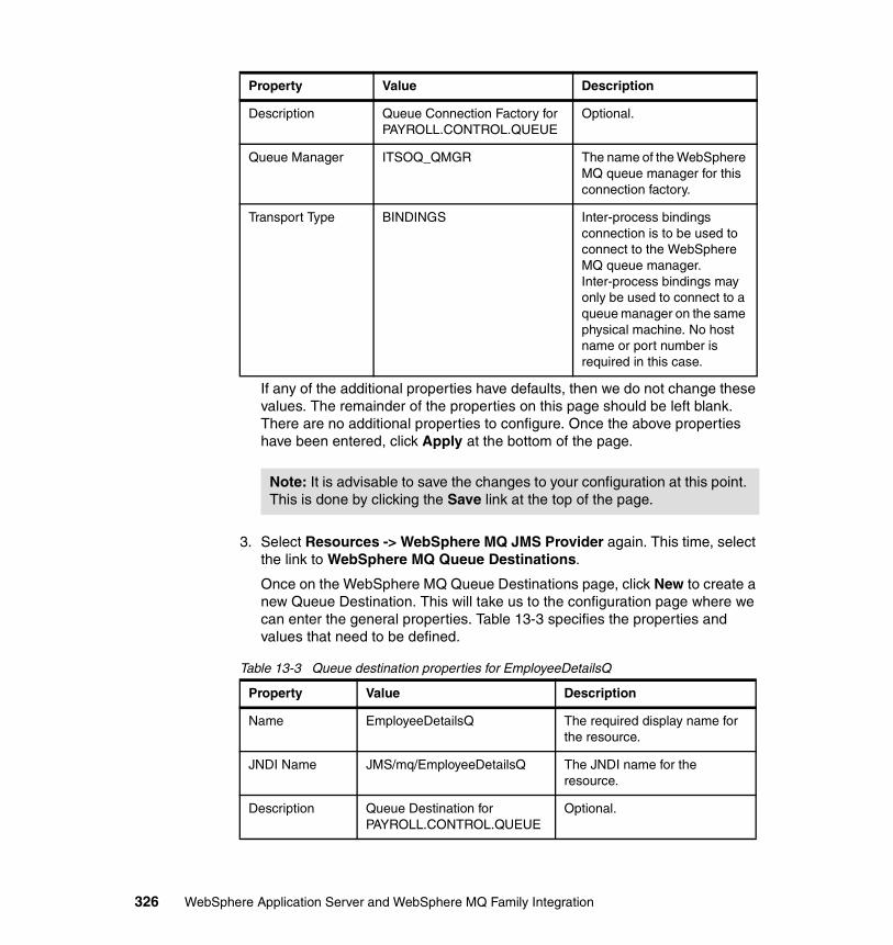
If any of the additional properties have defaults, then we do not change these values. The remainder of the properties on this page should be left blank. There are no additional properties to configure. Once the above properties have been entered, click Apply at the bottom of the page.
3. Select Resources -> WebSphere MQ JMS Provider again. This time, select the link to WebSphere MQ Queue Destinations.
Once on the WebSphere MQ Queue Destinations page, click New to create a new Queue Destination. This will take us to the configuration page where we can enter the general properties. Table 13-3 specifies the properties and values that need to be defined.
Table 13-3 Queue destination properties for EmployeeDetailsQ
Description Queue Connection Factory for PAYROLL.CONTROL.QUEUE
Optional.
Queue Manager ITSOQ_QMGR The name of the WebSphere MQ queue manager for this connection factory.
Transport Type BINDINGS Inter-process bindings connection is to be used to connect to the WebSphere MQ queue manager. Inter-process bindings may only be used to connect to a queue manager on the same physical machine. No host name or port number is required in this case.
Note: It is advisable to save the changes to your configuration at this point. This is done by clicking the Save link at the top of the page.
Property Value Description
Name EmployeeDetailsQ The required display name for the resource.
JNDI Name JMS/mq/EmployeeDetailsQ The JNDI name for the resource.
Description Queue Destination for PAYROLL.CONTROL.QUEUE
Optional.
Property Value Description
326 WebSphere Application Server and WebSphere MQ Family Integration
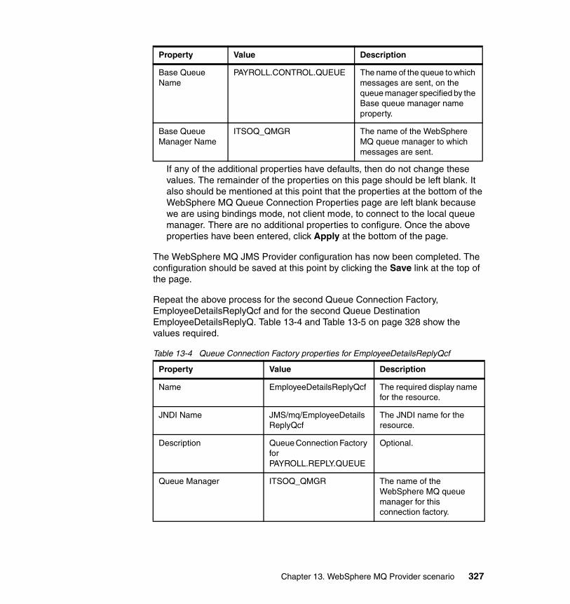
If any of the additional properties have defaults, then do not change these values. The remainder of the properties on this page should be left blank. It also should be mentioned at this point that the properties at the bottom of the WebSphere MQ Queue Connection Properties page are left blank because we are using bindings mode, not client mode, to connect to the local queue manager. There are no additional properties to configure. Once the above properties have been entered, click Apply at the bottom of the page.
The WebSphere MQ JMS Provider configuration has now been completed. The configuration should be saved at this point by clicking the Save link at the top of the page.
Repeat the above process for the second Queue Connection Factory, EmployeeDetailsReplyQcf and for the second Queue Destination EmployeeDetailsReplyQ. Table 13-4 and Table 13-5 on page 328 show the values required.
Table 13-4 Queue Connection Factory properties for EmployeeDetailsReplyQcf
Base Queue Name
PAYROLL.CONTROL.QUEUE The name of the queue to which messages are sent, on the queue manager specified by the Base queue manager name property.
Base Queue Manager Name
ITSOQ_QMGR The name of the WebSphere MQ queue manager to which messages are sent.
Property Value Description
Name EmployeeDetailsReplyQcf The required display name for the resource.
JNDI Name JMS/mq/EmployeeDetailsReplyQcf
The JNDI name for the resource.
Description Queue Connection Factory for PAYROLL.REPLY.QUEUE
Optional.
Queue Manager ITSOQ_QMGR The name of the WebSphere MQ queue manager for this connection factory.
Property Value Description
Chapter 13. WebSphere MQ Provider scenario 327
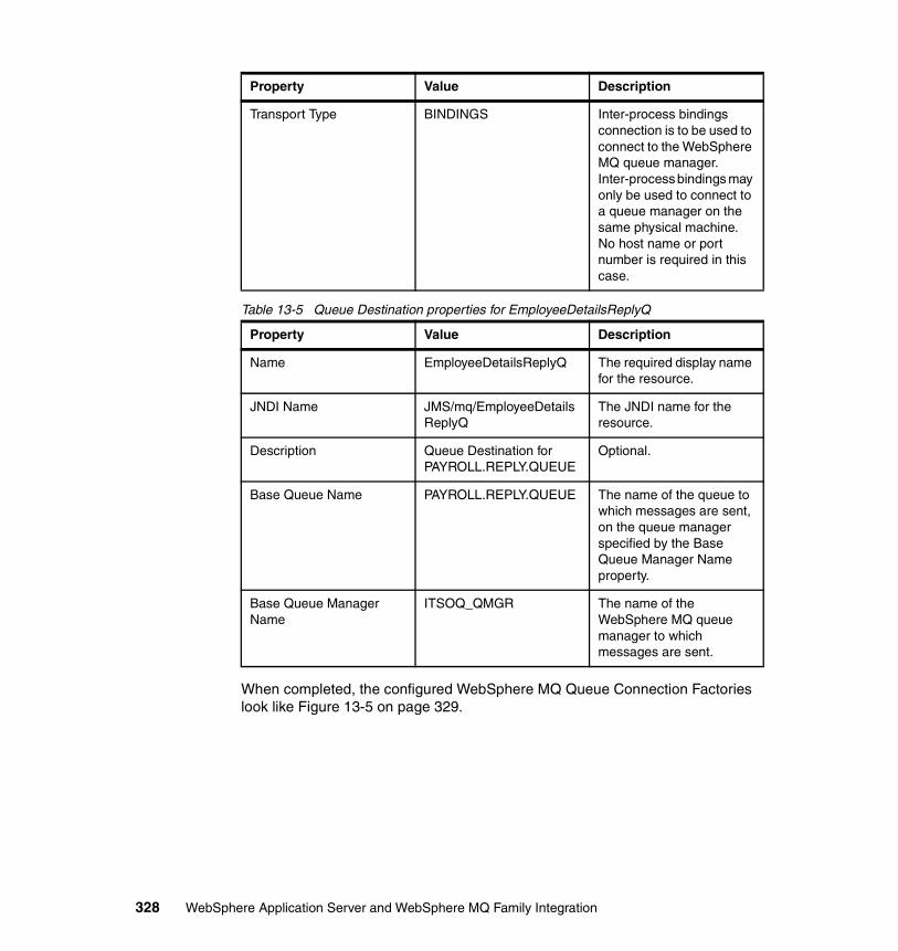
Table 13-5 Queue Destination properties for EmployeeDetailsReplyQ
When completed, the configured WebSphere MQ Queue Connection Factories look like Figure 13-5 on page 329.
Transport Type BINDINGS Inter-process bindings connection is to be used to connect to the WebSphere MQ queue manager. Inter-process bindings may only be used to connect to a queue manager on the same physical machine. No host name or port number is required in this case.
Property Value Description
Name EmployeeDetailsReplyQ The required display name for the resource.
JNDI Name JMS/mq/EmployeeDetailsReplyQ
The JNDI name for the resource.
Description Queue Destination for PAYROLL.REPLY.QUEUE
Optional.
Base Queue Name PAYROLL.REPLY.QUEUE The name of the queue to which messages are sent, on the queue manager specified by the Base Queue Manager Name property.
Base Queue Manager Name
ITSOQ_QMGR The name of the WebSphere MQ queue manager to which messages are sent.
Property Value Description
328 WebSphere Application Server and WebSphere MQ Family Integration
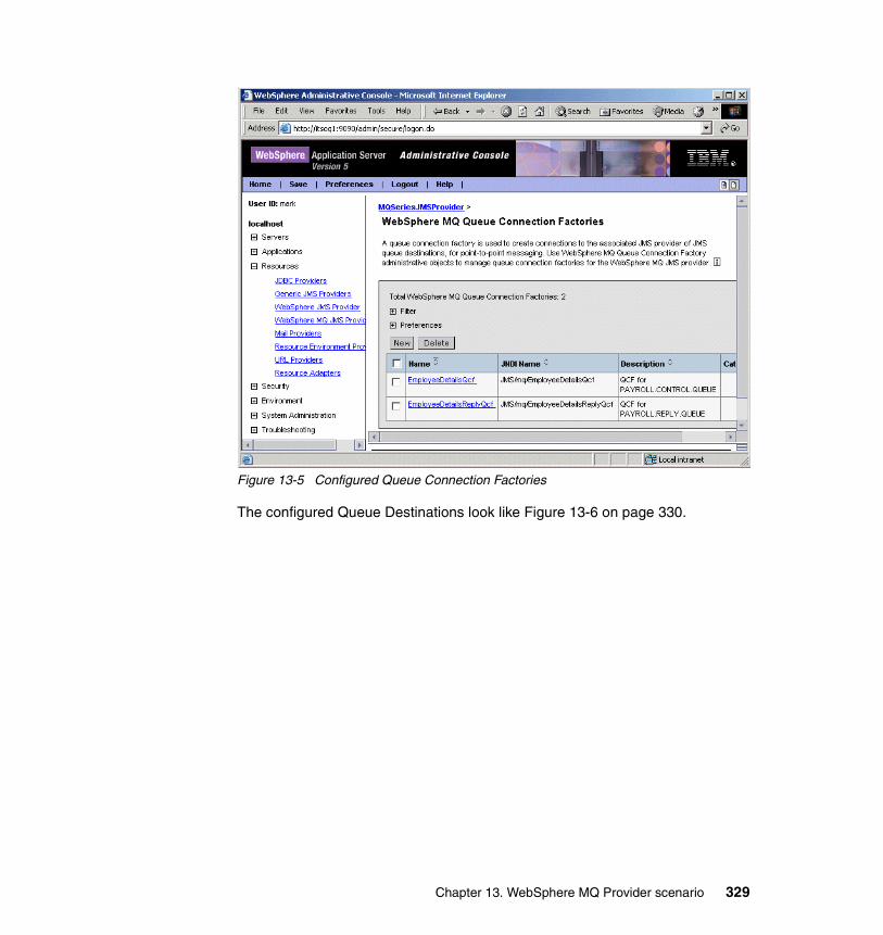
Figure 13-5 Configured Queue Connection Factories
The configured Queue Destinations look like Figure 13-6 on page 330.
Chapter 13. WebSphere MQ Provider scenario 329
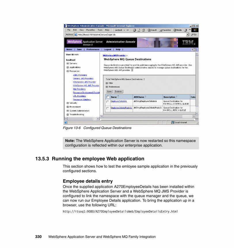
Figure 13-6 Configured Queue Destinations
13.5.3 Running the employee Web applicationThis section shows how to test the emloyee sample application in the previously configured sections.
Employee details entryOnce the supplied application A270EmployeeDetails has been installed within the WebSphere Application Server and a WebSphere MQ JMS Provider is configured to link the namespace with the queue manager and the queue, we can now run our Employee Details application. To bring the application up in a browser, use the following URL:
http://itsoq1:9080/A270EmployeeDetailsWeb/EmployeeDetailsEntry.html
Note: The WebSphere Application Server is now restarted so this namespace configuration is reflected within our enterprise application.
330 WebSphere Application Server and WebSphere MQ Family Integration
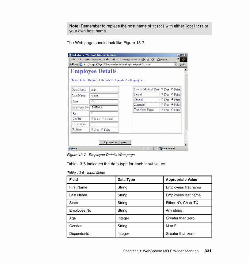
The Web page should look like Figure 13-7.
Figure 13-7 Employee Details Web page
Table 13-6 indicates the data type for each input value:
Table 13-6 Input fields
Note: Remember to replace the host name of itsoq1 with either localhost or your own host name.
Field Data Type Appropriate Value
First Name String Employees first name
Last Name String Employees last name
State String Either NY, CA or TX
Employee No String Any string
Age Integer Greater than zero
Gender String M or F
Dependents Integer Greater than zero
Chapter 13. WebSphere MQ Provider scenario 331
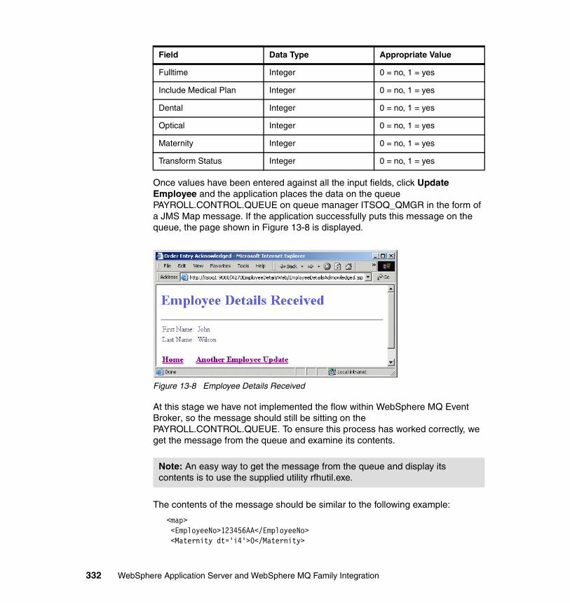
Once values have been entered against all the input fields, click Update Employee and the application places the data on the queue PAYROLL.CONTROL.QUEUE on queue manager ITSOQ_QMGR in the form of a JMS Map message. If the application successfully puts this message on the queue, the page shown in Figure 13-8 is displayed.
Figure 13-8 Employee Details Received
At this stage we have not implemented the flow within WebSphere MQ Event Broker, so the message should still be sitting on the PAYROLL.CONTROL.QUEUE. To ensure this process has worked correctly, we get the message from the queue and examine its contents.
The contents of the message should be similar to the following example:
<map> <EmployeeNo>123456AA</EmployeeNo> <Maternity dt='i4'>0</Maternity>
Fulltime Integer 0 = no, 1 = yes
Include Medical Plan Integer 0 = no, 1 = yes
Dental Integer 0 = no, 1 = yes
Optical Integer 0 = no, 1 = yes
Maternity Integer 0 = no, 1 = yes
Transform Status Integer 0 = no, 1 = yes
Note: An easy way to get the message from the queue and display its contents is to use the supplied utility rfhutil.exe.
Field Data Type Appropriate Value
332 WebSphere Application Server and WebSphere MQ Family Integration
<IncludeHealthPlan dt='i4'>1</IncludeHealthPlan> <Dependents dt='i4'>1</Dependents> <TransformStatus dt='i4'>1</TransformStatus> <LastName>Wilson</LastName> <FirstName>John</FirstName> <Gender>M</Gender> <Fulltime dt='i4'>1</Fulltime> <State>NY</State> <Optical dt='i4'>0</Optical> <Age dt='i4'>33</Age> <Dental dt='i4'>1</Dental></map>
Employee details replyAnother Web application is available to get the reply message from the PAYROLL.REPLY.QUEUE once it has been processed and returned. This application is run by using the following URL:
http://itsoq1:9080/A270EmployeeDetailsWeb/EmployeeDetailsReply.jsp
To test this application, there should be a message on queue PAYROLL.REPLY.QUEUE. When ready to test, click the Get Message button. An example of this Web application is shown in Figure 13-9 on page 334.
Chapter 13. WebSphere MQ Provider scenario 333
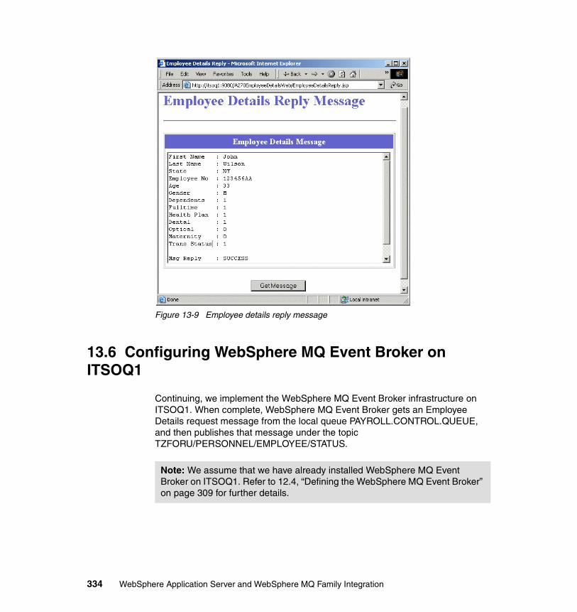
Figure 13-9 Employee details reply message
13.6 Configuring WebSphere MQ Event Broker on ITSOQ1
Continuing, we implement the WebSphere MQ Event Broker infrastructure on ITSOQ1. When complete, WebSphere MQ Event Broker gets an Employee Details request message from the local queue PAYROLL.CONTROL.QUEUE, and then publishes that message under the topic TZFORU/PERSONNEL/EMPLOYEE/STATUS.
Note: We assume that we have already installed WebSphere MQ Event Broker on ITSOQ1. Refer to 12.4, “Defining the WebSphere MQ Event Broker” on page 309 for further details.
334 WebSphere Application Server and WebSphere MQ Family Integration
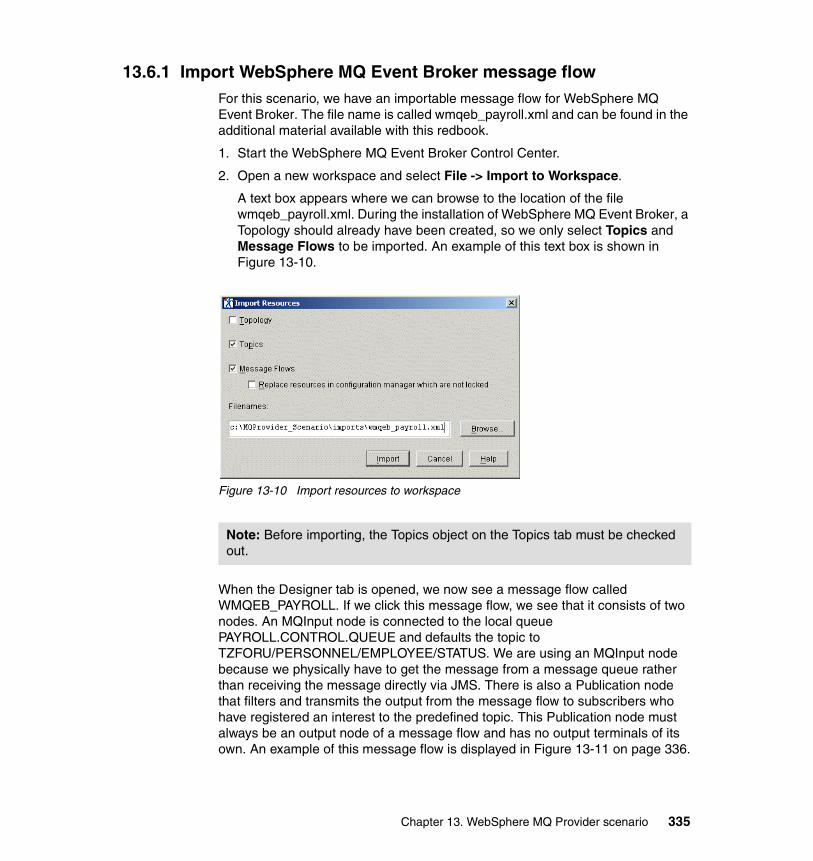
13.6.1 Import WebSphere MQ Event Broker message flowFor this scenario, we have an importable message flow for WebSphere MQ Event Broker. The file name is called wmqeb_payroll.xml and can be found in the additional material available with this redbook.
1. Start the WebSphere MQ Event Broker Control Center.
2. Open a new workspace and select File -> Import to Workspace.
A text box appears where we can browse to the location of the file wmqeb_payroll.xml. During the installation of WebSphere MQ Event Broker, a Topology should already have been created, so we only select Topics and Message Flows to be imported. An example of this text box is shown in Figure 13-10.
Figure 13-10 Import resources to workspace
When the Designer tab is opened, we now see a message flow called WMQEB_PAYROLL. If we click this message flow, we see that it consists of two nodes. An MQInput node is connected to the local queue PAYROLL.CONTROL.QUEUE and defaults the topic to TZFORU/PERSONNEL/EMPLOYEE/STATUS. We are using an MQInput node because we physically have to get the message from a message queue rather than receiving the message directly via JMS. There is also a Publication node that filters and transmits the output from the message flow to subscribers who have registered an interest to the predefined topic. This Publication node must always be an output node of a message flow and has no output terminals of its own. An example of this message flow is displayed in Figure 13-11 on page 336.
Note: Before importing, the Topics object on the Topics tab must be checked out.
Chapter 13. WebSphere MQ Provider scenario 335
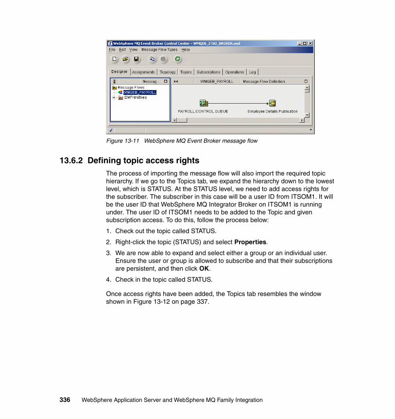
Figure 13-11 WebSphere MQ Event Broker message flow
13.6.2 Defining topic access rightsThe process of importing the message flow will also import the required topic hierarchy. If we go to the Topics tab, we expand the hierarchy down to the lowest level, which is STATUS. At the STATUS level, we need to add access rights for the subscriber. The subscriber in this case will be a user ID from ITSOM1. It will be the user ID that WebSphere MQ Integrator Broker on ITSOM1 is running under. The user ID of ITSOM1 needs to be added to the Topic and given subscription access. To do this, follow the process below:
1. Check out the topic called STATUS.
2. Right-click the topic (STATUS) and select Properties.
3. We are now able to expand and select either a group or an individual user. Ensure the user or group is allowed to subscribe and that their subscriptions are persistent, and then click OK.
4. Check in the topic called STATUS.
Once access rights have been added, the Topics tab resembles the window shown in Figure 13-12 on page 337.
336 WebSphere Application Server and WebSphere MQ Family Integration
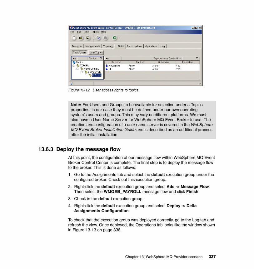
Figure 13-12 User access rights to topics
13.6.3 Deploy the message flowAt this point, the configuration of our message flow within WebSphere MQ Event Broker Control Center is complete. The final step is to deploy the message flow to the broker. This is done as follows:
1. Go to the Assignments tab and select the default execution group under the configured broker. Check out this execution group.
2. Right-click the default execution group and select Add -> Message Flow. Then select the WMQEB_PAYROLL message flow and click Finish.
3. Check in the default execution group.
4. Right-click the default execution group and select Deploy -> Delta Assignments Configuration.
To check that the execution group was deployed correctly, go to the Log tab and refresh the view. Once deployed, the Operations tab looks like the window shown in Figure 13-13 on page 338.
Note: For Users and Groups to be available for selection under a Topics properties, in our case they must be defined under our own operating system’s users and groups. This may vary on different platforms. We must also have a User Name Server for WebSphere MQ Event Broker to use. The creation and configuration of a user name server is covered in the WebSphere MQ Event Broker Installation Guide and is described as an additional process after the initial installation.
Chapter 13. WebSphere MQ Provider scenario 337
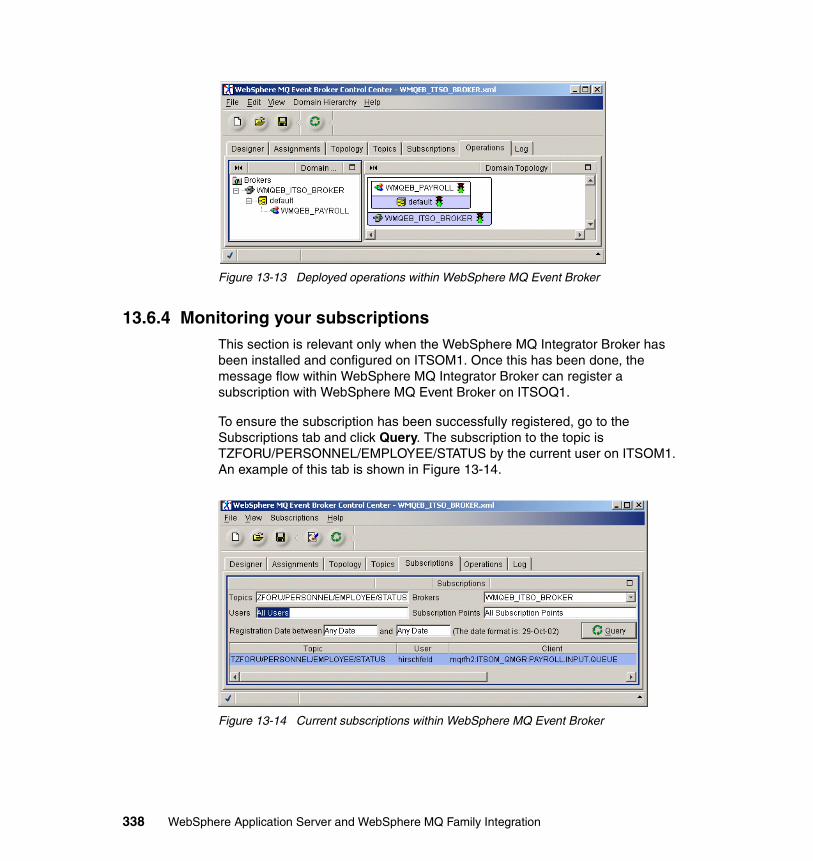
Figure 13-13 Deployed operations within WebSphere MQ Event Broker
13.6.4 Monitoring your subscriptionsThis section is relevant only when the WebSphere MQ Integrator Broker has been installed and configured on ITSOM1. Once this has been done, the message flow within WebSphere MQ Integrator Broker can register a subscription with WebSphere MQ Event Broker on ITSOQ1.
To ensure the subscription has been successfully registered, go to the Subscriptions tab and click Query. The subscription to the topic is TZFORU/PERSONNEL/EMPLOYEE/STATUS by the current user on ITSOM1. An example of this tab is shown in Figure 13-14.
Figure 13-14 Current subscriptions within WebSphere MQ Event Broker
338 WebSphere Application Server and WebSphere MQ Family Integration
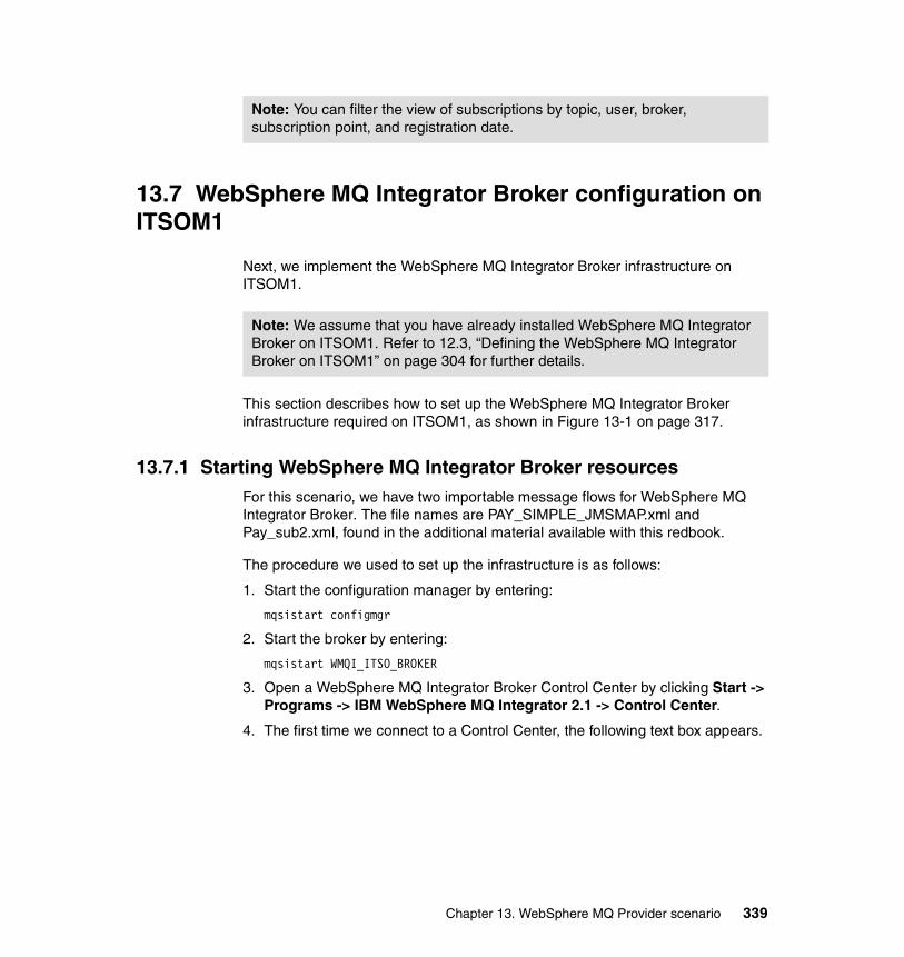
13.7 WebSphere MQ Integrator Broker configuration on ITSOM1
Next, we implement the WebSphere MQ Integrator Broker infrastructure on ITSOM1.
This section describes how to set up the WebSphere MQ Integrator Broker infrastructure required on ITSOM1, as shown in Figure 13-1 on page 317.
13.7.1 Starting WebSphere MQ Integrator Broker resourcesFor this scenario, we have two importable message flows for WebSphere MQ Integrator Broker. The file names are PAY_SIMPLE_JMSMAP.xml and Pay_sub2.xml, found in the additional material available with this redbook.
The procedure we used to set up the infrastructure is as follows:
1. Start the configuration manager by entering:
mqsistart configmgr
2. Start the broker by entering:
mqsistart WMQI_ITSO_BROKER
3. Open a WebSphere MQ Integrator Broker Control Center by clicking Start -> Programs -> IBM WebSphere MQ Integrator 2.1 -> Control Center.
4. The first time we connect to a Control Center, the following text box appears.
Note: You can filter the view of subscriptions by topic, user, broker, subscription point, and registration date.
Note: We assume that you have already installed WebSphere MQ Integrator Broker on ITSOM1. Refer to 12.3, “Defining the WebSphere MQ Integrator Broker on ITSOM1” on page 304 for further details.
Chapter 13. WebSphere MQ Provider scenario 339
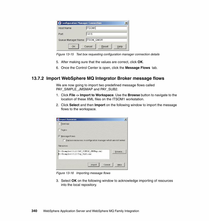
Figure 13-15 Text box requesting configuration manager connection details
5. After making sure that the values are correct, click OK.
6. Once the Control Center is open, click the Message Flows tab.
13.7.2 Import WebSphere MQ Integrator Broker message flowsWe are now going to import two predefined message flows called PAY_SIMPLE_JMSMAP and PAY_SUB2.
1. Click File -> Import to Workspace. Use the Browse button to navigate to the location of these XML files on the ITSOM1 workstation.
2. Click Select and then Import on the following window to import the message flows to the workspace.
Figure 13-16 Importing message flows
3. Select OK on the following window to acknowledge importing of resources into the local repository.
340 WebSphere Application Server and WebSphere MQ Family Integration
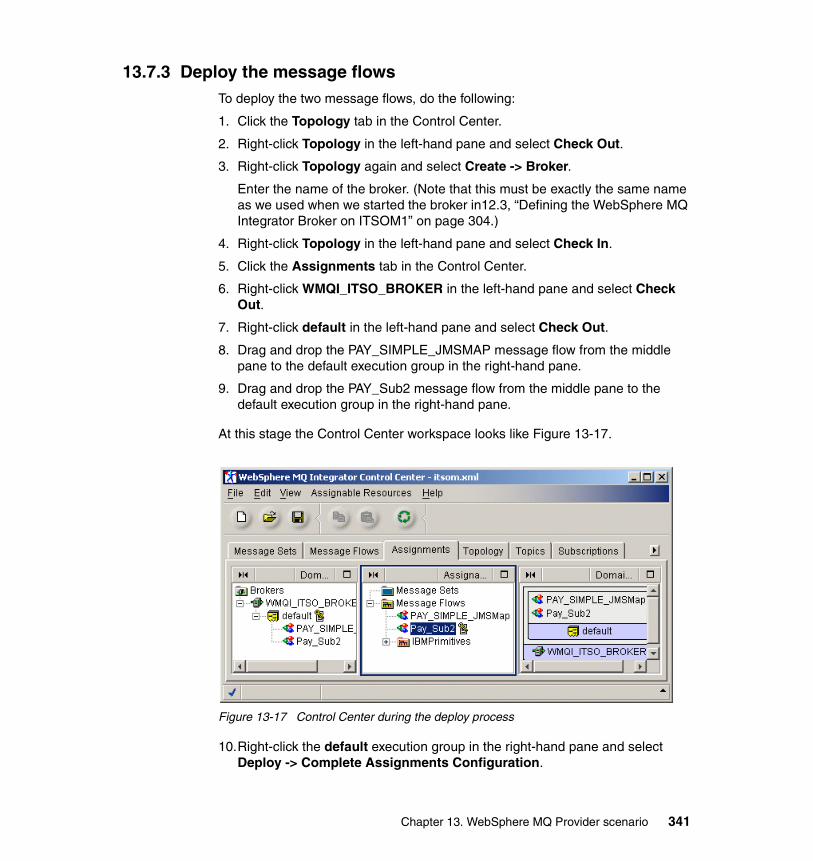
13.7.3 Deploy the message flowsTo deploy the two message flows, do the following:
1. Click the Topology tab in the Control Center.
2. Right-click Topology in the left-hand pane and select Check Out.
3. Right-click Topology again and select Create -> Broker.
Enter the name of the broker. (Note that this must be exactly the same name as we used when we started the broker in12.3, “Defining the WebSphere MQ Integrator Broker on ITSOM1” on page 304.)
4. Right-click Topology in the left-hand pane and select Check In.
5. Click the Assignments tab in the Control Center.
6. Right-click WMQI_ITSO_BROKER in the left-hand pane and select Check Out.
7. Right-click default in the left-hand pane and select Check Out.
8. Drag and drop the PAY_SIMPLE_JMSMAP message flow from the middle pane to the default execution group in the right-hand pane.
9. Drag and drop the PAY_Sub2 message flow from the middle pane to the default execution group in the right-hand pane.
At this stage the Control Center workspace looks like Figure 13-17.
Figure 13-17 Control Center during the deploy process
10.Right-click the default execution group in the right-hand pane and select Deploy -> Complete Assignments Configuration.
Chapter 13. WebSphere MQ Provider scenario 341
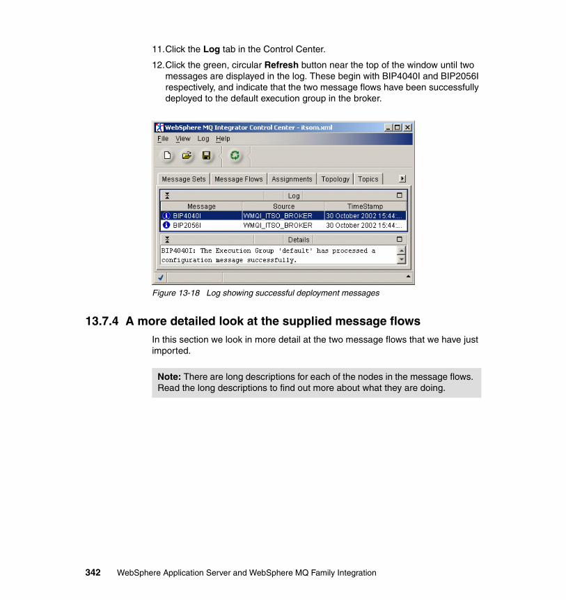
11.Click the Log tab in the Control Center.
12.Click the green, circular Refresh button near the top of the window until two messages are displayed in the log. These begin with BIP4040I and BIP2056I respectively, and indicate that the two message flows have been successfully deployed to the default execution group in the broker.
Figure 13-18 Log showing successful deployment messages
13.7.4 A more detailed look at the supplied message flowsIn this section we look in more detail at the two message flows that we have just imported.
Note: There are long descriptions for each of the nodes in the message flows. Read the long descriptions to find out more about what they are doing.
342 WebSphere Application Server and WebSphere MQ Family Integration
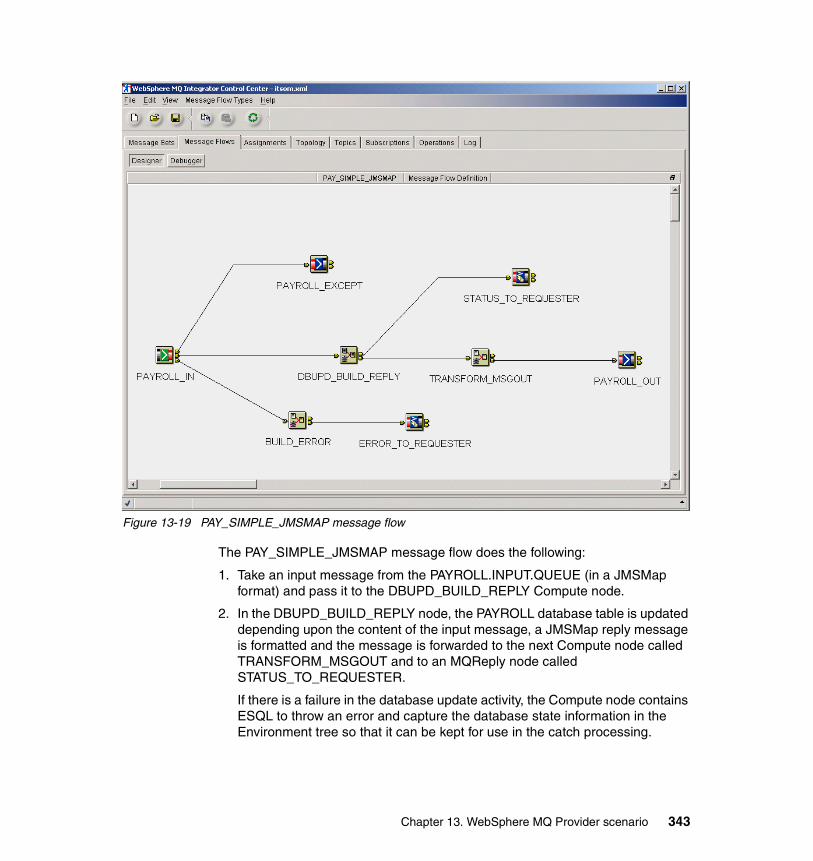
Figure 13-19 PAY_SIMPLE_JMSMAP message flow
The PAY_SIMPLE_JMSMAP message flow does the following:
1. Take an input message from the PAYROLL.INPUT.QUEUE (in a JMSMap format) and pass it to the DBUPD_BUILD_REPLY Compute node.
2. In the DBUPD_BUILD_REPLY node, the PAYROLL database table is updated depending upon the content of the input message, a JMSMap reply message is formatted and the message is forwarded to the next Compute node called TRANSFORM_MSGOUT and to an MQReply node called STATUS_TO_REQUESTER.
If there is a failure in the database update activity, the Compute node contains ESQL to throw an error and capture the database state information in the Environment tree so that it can be kept for use in the catch processing.
Chapter 13. WebSphere MQ Provider scenario 343
Although we do a database update and a reply message, since the entire message flow is running under control of a globally coordinated unit of work, those updates are not yet committed.
The TransactionStatus coming in should only ever be ADD or UPD, since that is what the subscription requested. However, if some sort of rogue message comes in with a different TransformStatus, an error will be thrown. In this case, the text of the error message will indicate the value of the bad TransactionStatus and that will be captured in the ExceptionList for use in the catch processing.
3. In the TRANSFORM_MSGOUT node, the incoming JMSMap formatted messaged is transformed to generic XML. Based on the incoming State (NY, TX or CA), a destination list entry is built in the LocalEnvironment tree and the message is forwarded to the PAYROLL_OUT MQOutput node.
4. The STATUS_TO_REQUESTER MQReply node sends a JMSMap reply message with status of the update to the queue specified in the ReplyToQ in the message descriptor of the incoming message.
5. The PAYROLL_OUT MQOutput node uses the destination list to determine where to put the message it has received.
In the event of an error in any of the above:
1. The message is rolled back to the MQInput node called PAYROLL_IN.
2. The message is then propagated out the catch terminal, through a Compute node called BUILD_ERROR that will determine if there was a database error.
3. If so, the database status information will be added to the JMSMap message. For all other error conditions, the error information will be taken from the ExceptionList message and built into the JMSMap message. The Compute node will use the PROPAGATE statement to send the output message to the MQReply node called ERROR_TO_REQUESTER, which will put to the reply queue outside of the unit of work.
4. Control then returns to the BUILD_ERROR Compute node.
5. The Compute node will use an ESQL throw statement to cause the message to be rolled back to the MQInput node again.
6. Finally, when this final rollback occurs, the message is propagated out the failure terminal of the MQInput node where the PAYROLL_EXCEPT MQOutput node PUTs the initial message on a local queue called PAYROLL.EXCEPTION.
See Appendix B, “WebSphere MQ Provider scenario” on page 415 for details on the processing performed by the ESQL in the Compute node.
344 WebSphere Application Server and WebSphere MQ Family Integration
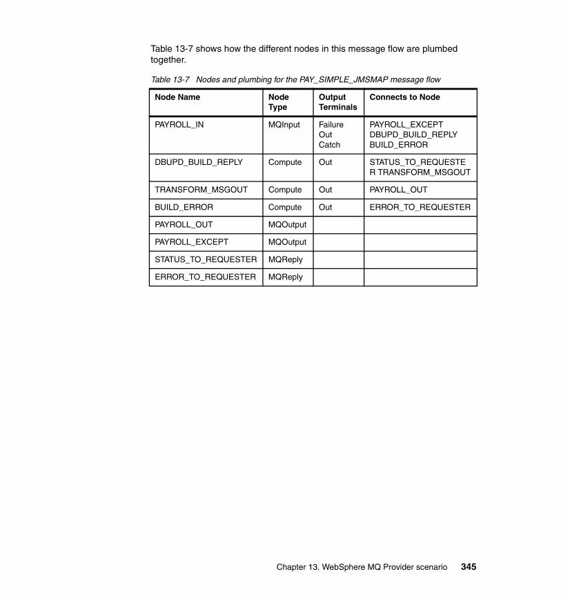
Table 13-7 shows how the different nodes in this message flow are plumbed together.
Table 13-7 Nodes and plumbing for the PAY_SIMPLE_JMSMAP message flow
Node Name Node Type
Output Terminals
Connects to Node
PAYROLL_IN MQInput FailureOutCatch
PAYROLL_EXCEPTDBUPD_BUILD_REPLYBUILD_ERROR
DBUPD_BUILD_REPLY Compute Out STATUS_TO_REQUESTER TRANSFORM_MSGOUT
TRANSFORM_MSGOUT Compute Out PAYROLL_OUT
BUILD_ERROR Compute Out ERROR_TO_REQUESTER
PAYROLL_OUT MQOutput
PAYROLL_EXCEPT MQOutput
STATUS_TO_REQUESTER MQReply
ERROR_TO_REQUESTER MQReply
Chapter 13. WebSphere MQ Provider scenario 345
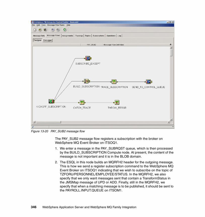
Figure 13-20 PAY_SUB2 message flow
The PAY_SUB2 message flow registers a subscription with the broker on WebSphere MQ Event Broker on ITSOQ1.
1. We enter a message in the PAY_SUBRQST queue, which is then processed by the BUILD_SUBSCRIPTION Compute node. At present, the content of the message is not important and it is in the BLOB domain.
2. The ESQL in this node builds an MQRFH2 header for the outgoing message. This is how we send a register subscription command to the WebSphere MQ Event Broker on ITSOQ1 indicating that we wish to subscribe on the topic of TZFORU/PERSONNEL/EMPLOYEE/STATUS. In the MQRFH2, we also specify that we only want messages sent that contain a TransformStatus in the JMSMap message of UPD or ADD. Finally, still in the MQRFH2, we specify that when a matching message is to be published, it should be sent to the PAYROLL.INPUT.QUEUE on ITSOM1.
346 WebSphere Application Server and WebSphere MQ Family Integration
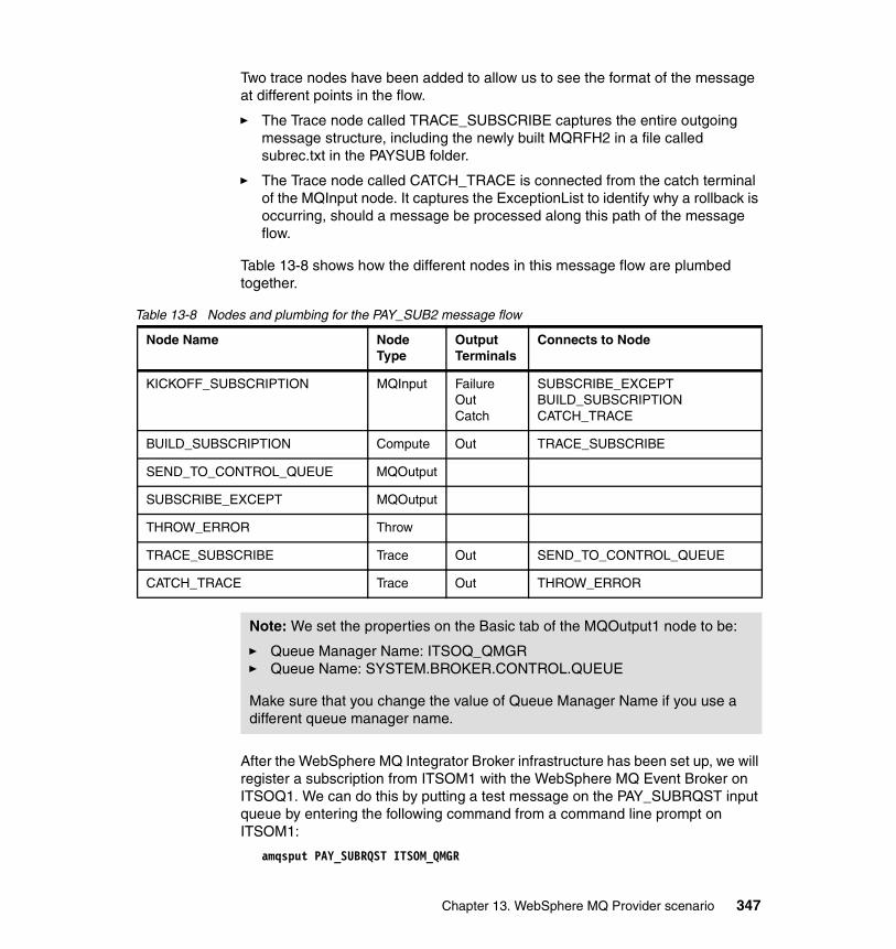
Two trace nodes have been added to allow us to see the format of the message at different points in the flow.
� The Trace node called TRACE_SUBSCRIBE captures the entire outgoing message structure, including the newly built MQRFH2 in a file called subrec.txt in the PAYSUB folder.
� The Trace node called CATCH_TRACE is connected from the catch terminal of the MQInput node. It captures the ExceptionList to identify why a rollback is occurring, should a message be processed along this path of the message flow.
Table 13-8 shows how the different nodes in this message flow are plumbed together.
Table 13-8 Nodes and plumbing for the PAY_SUB2 message flow
After the WebSphere MQ Integrator Broker infrastructure has been set up, we will register a subscription from ITSOM1 with the WebSphere MQ Event Broker on ITSOQ1. We can do this by putting a test message on the PAY_SUBRQST input queue by entering the following command from a command line prompt on ITSOM1:
amqsput PAY_SUBRQST ITSOM_QMGR
Node Name Node Type
Output Terminals
Connects to Node
KICKOFF_SUBSCRIPTION MQInput FailureOutCatch
SUBSCRIBE_EXCEPTBUILD_SUBSCRIPTIONCATCH_TRACE
BUILD_SUBSCRIPTION Compute Out TRACE_SUBSCRIBE
SEND_TO_CONTROL_QUEUE MQOutput
SUBSCRIBE_EXCEPT MQOutput
THROW_ERROR Throw
TRACE_SUBSCRIBE Trace Out SEND_TO_CONTROL_QUEUE
CATCH_TRACE Trace Out THROW_ERROR
Note: We set the properties on the Basic tab of the MQOutput1 node to be:
� Queue Manager Name: ITSOQ_QMGR � Queue Name: SYSTEM.BROKER.CONTROL.QUEUE
Make sure that you change the value of Queue Manager Name if you use a different queue manager name.
Chapter 13. WebSphere MQ Provider scenario 347

348 WebSphere Application Server and WebSphere MQ Family Integration
Chapter 14. Generic JMS Provider scenario
This scenario is designed to demonstrate the integration of WebSphere Application Server V5 with earlier versions of MQSeries. We integrate WebSphere Application Server with MQSeries V5.2.1, with the new WebSphere MQ Event Broker V2.1, and with WebSphere MQ Integrator Broker V2.1. This scenario is based on the same topology and business case as the MQ Provider scenario except for the fact that we will be integrating WebSphere Application Server V5 with MQSeries V5.2.1 by defining a Generic JMS Provider.
As in the MQ Provider scenario, we show how WebSphere MQ Event Broker can be used effectively within an enterprise and how WebSphere MQ Integrator Broker might be used when additional processing and database storage is required. We describe how distributed queuing through the use of clustering enables workload balancing and increases queue availability, enabling continuous operations.
In addition to the MQ Provider scenario, we demonstrate how to configure our JMS namespace externally to WebSphere Application Server by using the MQSeries MA88 SupportPac. We then link the external namespace with our Web application by using a Generic JMS Provider.
14
© Copyright IBM Corp. 2003. All rights reserved. 349
14.1 Generic JMS Provider and MQSeries V5.2.1The WebSphere Application Server Generic JMS Provider can be used to support other messaging providers. The JMS Embedded and MQ Providers both rely on WebSphere MQ V5.3.1. One possible other provider might be an earlier version of MQSeries. In our case, we have used MQSeries V5.2.1 for Windows with the MA88 SupportPac. By using an external provider, we establish our namespace externally to the WebSphere Application Server and use the Generic JMS Provider configuration to link the two together. By using a Generic JMS Provider with the earlier version of MQSeries, the Web application that was used in the MQ Provider scenario does not need to be modified and is oblivious to the differences in the configuration.
In this scenario we demonstrate the establishment of our namespace through the MA88 SupportPac and the configuration of the Generic JMS Provider within WebSphere Application Server. Since this scenario is similar to the MQ Provider scenario, all other configurations remain the same and rather than repeating them in this chapter, we make reference to them.
The business case for this scenario is identical to the business case for the MQ Provider scenario, except for the fact that TZFORU may already be in production with an earlier version of MQSeries on system 1 (ITSOQ1) and may not be in a position to upgrade to WebSphere MQ V5.3.1. For more information about the business case, refer to 13.1, “Business case for this scenario” on page 316.
The Generic JMS Provider scenario is illustrated in Figure 14-1 on page 351. The main difference is that queue manager ITSOQ_QMGR on ITSOQ1 is running on MQSeries V5.2.1 instead of WebSphere MQ V5.3.1.
350 WebSphere Application Server and WebSphere MQ Family Integration
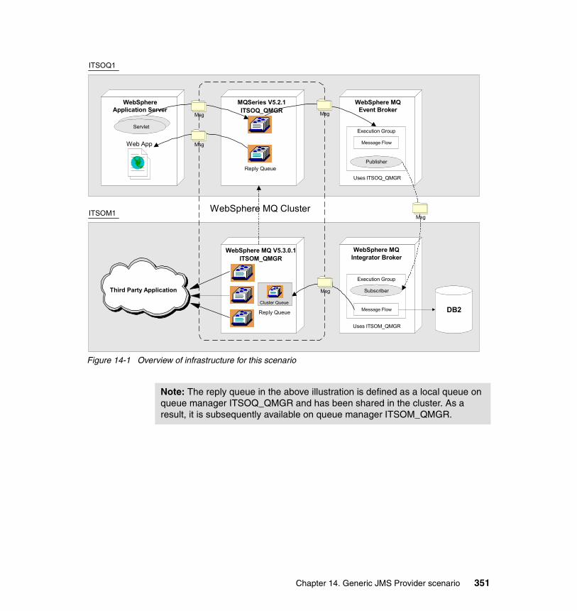
Figure 14-1 Overview of infrastructure for this scenario
WebSphere MQ Cluster
ITSOQ1
ITSOM1
WebSphereApplication Server
MQSeries V5.2.1ITSOQ_QMGR
WebSphere MQ V5.3.0.1ITSOM_QMGR
WebSphere MQEvent Broker
WebSphere MQIntegrator Broker
Msg Msg
DB2
Execution Group
Message Flow
Publisher
Execution Group
Message Flow
Subscriber
Msg
MsgWeb App
Uses ITSOQ_QMGR
Uses ITSOM_QMGR
Servlet
Third Party Application Msg
Reply Queue
Reply Queue
Cluster Queue
Note: The reply queue in the above illustration is defined as a local queue on queue manager ITSOQ_QMGR and has been shared in the cluster. As a result, it is subsequently available on queue manager ITSOM_QMGR.
Chapter 14. Generic JMS Provider scenario 351
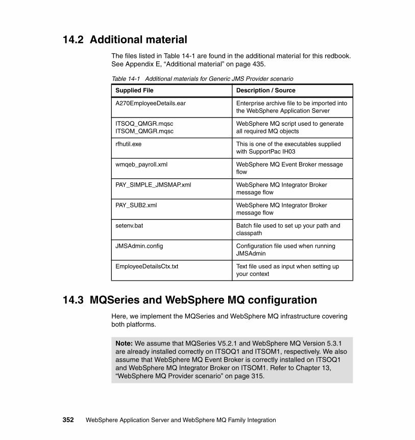
14.2 Additional materialThe files listed in Table 14-1 are found in the additional material for this redbook. See Appendix E, “Additional material” on page 435.
Table 14-1 Additional materials for Generic JMS Provider scenario
14.3 MQSeries and WebSphere MQ configurationHere, we implement the MQSeries and WebSphere MQ infrastructure covering both platforms.
Supplied File Description / Source
A270EmployeeDetails.ear Enterprise archive file to be imported into the WebSphere Application Server
ITSOQ_QMGR.mqscITSOM_QMGR.mqsc
WebSphere MQ script used to generate all required MQ objects
rfhutil.exe This is one of the executables supplied with SupportPac IH03
wmqeb_payroll.xml WebSphere MQ Event Broker message flow
PAY_SIMPLE_JMSMAP.xml WebSphere MQ Integrator Broker message flow
PAY_SUB2.xml WebSphere MQ Integrator Broker message flow
setenv.bat Batch file used to set up your path and classpath
JMSAdmin.config Configuration file used when running JMSAdmin
EmployeeDetailsCtx.txt Text file used as input when setting up your context
Note: We assume that MQSeries V5.2.1 and WebSphere MQ Version 5.3.1 are already installed correctly on ITSOQ1 and ITSOM1, respectively. We also assume that WebSphere MQ Event Broker is correctly installed on ITSOQ1 and WebSphere MQ Integrator Broker on ITSOM1. Refer to Chapter 13, “WebSphere MQ Provider scenario” on page 315.
352 WebSphere Application Server and WebSphere MQ Family Integration
14.4 JNDI namspace definition on ITSOQ1In this section, we establish our JNDI namespace by using the JMS administration tool that comes with the MA88 SupportPac.
The installation of the MA88 SupportPac (MQSeries classes for Java and MQSeries classes for JMS) will have installed an install_dir\java\bin directory, which contains the JMS administration tool called JMSAdmin. By running this administration tool, we can define our namespace.
The administration tool has a command-line interface. We can use this interactively or use it to start a batch process. To create our namespace object, we use the tool to start a batch process. But before we can do this, we must ensure the tool will successfully run in interactive mode. The interactive mode provides a command prompt where you can enter administrative commands. In the batch mode, the command to start the tool includes the name of a file that contains an administration command script. In the additional material for this chapter, we have supplied a file that contains the command script.
The JMSAdmin tool requires a configuration file to run. By default, this file is called the same name, JMSAdmin.config. In this file, we specify what provider we want to use to create our namespace. A sample JMSAdmin.config file has also been included in the additional material supplied with this redbook. For this scenario, we decided to define our namespace in a file system. This is because we wanted to make our namespace persistent, as opposed to the other types of providers, which are nonpersistent. In this scenario, we found that the WebSphere Application Server may need to be restarted and if a nonpersistent provider was being used, we would lose our namespace at this point.
We have broken down this process into three steps to help alleviate any problems using this tool. The steps are:
1. Configuring our environment2. Running JMSAdmin3. Creating our namespace objects
Note: We assume that MQSeries V5.2.1 and the MA88 SupportPac are already installed correctly on ITSOQ1 instead of the previously installed WebSphere MQ V5.3.1. Refer to Chapter 13, “WebSphere MQ Provider scenario” on page 315 for further details.
Chapter 14. Generic JMS Provider scenario 353
14.4.1 Environment configurationBefore we can run the JMSAdmin tool, we need to establish the correct environment. This means that the configuration file JMSAdmin.config must have the correct properties and that we have set up the correct path and classpath.
JMSAdmin.configThe JMSAdmin.config file must be in the same directory as the tool or in the system path (it is usually kept in the same directory). We have supplied a sample JMSAdmin.config in the additional material for this chapter. In the sample, we have already defined the correct settings. There are three lines in this configuration file that we need to consider here. These are:
� The JMS provider� The URL address� The security setting
The JMS provider should be set to the following:
INITIAL_CONTEXT_FACTORY=com.sun.jndi.fscontext.RefFSContextFactory
The URL address should be set to the following:
PROVIDER_URL=file:/C:/JNDI-Directory
At this point, we need to create the directory called C:/JNDI-Directory if it does not already exist. We can also modify the URL address to any drive and directory, as long as that directory exists and is also accessible by the WebSphere Application Server.
The security authentication should be set to the following:
SECURITY_AUTHENTICATION=none
Setting the path and classpathSetting the correct path and classpath is usually the most common problem with running the JMSAdmin tool. Rather than permanently setting our system path and classpath, we decided to temporarily set them before the configuration tool is run. We have supplied a batch file to help with this process. This batch file is
Important: The configuration above is case sensitive. Be careful to get the case correct.
Note: This Provider URL address should be noted, since we later use this exact same address when we configure the Generic JMS Provider within WebSphere Application Server.
354 WebSphere Application Server and WebSphere MQ Family Integration

called setenv.bat and is found in the additional material for this chapter. By running this batch file before we run JMSAdmin, our environment is correctly configured.
The contents for the setenv.bat batch file is shown in Example 14-1.
Example 14-1 setenv.bat
@echo off@rem The WebSphere Application Server home directoryset WAS_HOME=C:\was
@rem The location of the MQSeries Classes for Javaset MQ_JAVA_INSTALL_PATH=C:\mq\Java
@rem Java runtimeset JAVA_HOME=C:\was\java\jre\bin
@rem MQ JMS jar filesset MQ=%MQ%;%MQ_JAVA_INSTALL_PATH%\libset MQ=%MQ%;%MQ_JAVA_INSTALL_PATH%\lib\com.ibm.mq.jarset MQ=%MQ%;%MQ_JAVA_INSTALL_PATH%\lib\com.ibm.mqjms.jarset MQ=%MQ%;%MQ_JAVA_INSTALL_PATH%\lib\jms.jarset MQ=%MQ%;%MQ_JAVA_INSTALL_PATH%\lib\jndi.jarset MQ=%MQ%;%MQ_JAVA_INSTALL_PATH%\lib\connector.jarset MQ=%MQ%;%MQ_JAVA_INSTALL_PATH%\lib\fscontext.jarset MQ=%MQ%;%MQ_JAVA_INSTALL_PATH%\lib\providerutil.jar
@rem needed to use WebSphere name service for JNDIset WebSphereCP=%WAS_HOME%\lib\naming.jar
set CLASSPATH=%MQ%;%WebSphereCP%;%CLASSPATH%
set PATH=%JAVA_HOME%;%MQ_JAVA_INSTALL_PATH%\lib;%MQ_JAVA_INSTALL_PATH%\bin;%PATH%;
If the location of the installed WebSphere Application Server, MQSeries, and the MA88 SupportPac (MQSeries classes for Java) differ from those defined in the above batch file, then these need to be modified. This batch file should be placed in the same directory as JMSAdmin.
Note: This batch file is only designed for a Windows-based system.
Chapter 14. Generic JMS Provider scenario 355
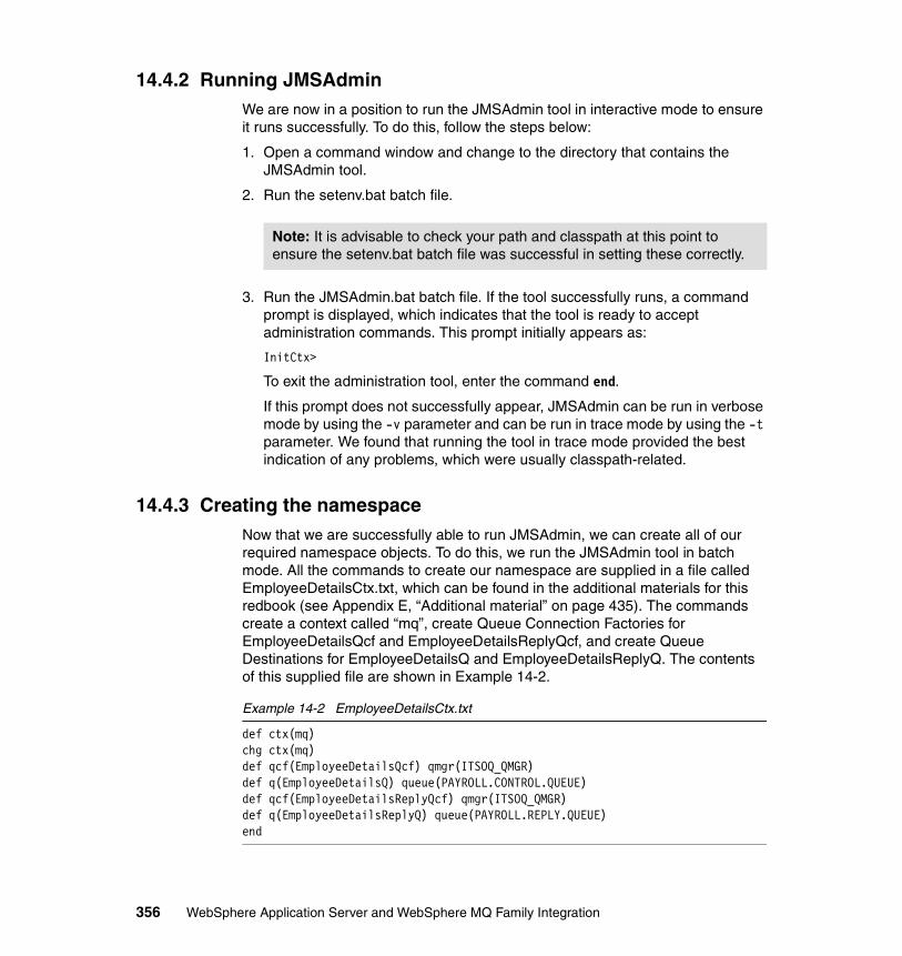
14.4.2 Running JMSAdminWe are now in a position to run the JMSAdmin tool in interactive mode to ensure it runs successfully. To do this, follow the steps below:
1. Open a command window and change to the directory that contains the JMSAdmin tool.
2. Run the setenv.bat batch file.
3. Run the JMSAdmin.bat batch file. If the tool successfully runs, a command prompt is displayed, which indicates that the tool is ready to accept administration commands. This prompt initially appears as:
InitCtx>
To exit the administration tool, enter the command end.
If this prompt does not successfully appear, JMSAdmin can be run in verbose mode by using the -v parameter and can be run in trace mode by using the -t parameter. We found that running the tool in trace mode provided the best indication of any problems, which were usually classpath-related.
14.4.3 Creating the namespaceNow that we are successfully able to run JMSAdmin, we can create all of our required namespace objects. To do this, we run the JMSAdmin tool in batch mode. All the commands to create our namespace are supplied in a file called EmployeeDetailsCtx.txt, which can be found in the additional materials for this redbook (see Appendix E, “Additional material” on page 435). The commands create a context called “mq”, create Queue Connection Factories for EmployeeDetailsQcf and EmployeeDetailsReplyQcf, and create Queue Destinations for EmployeeDetailsQ and EmployeeDetailsReplyQ. The contents of this supplied file are shown in Example 14-2.
Example 14-2 EmployeeDetailsCtx.txt
def ctx(mq)chg ctx(mq)def qcf(EmployeeDetailsQcf) qmgr(ITSOQ_QMGR)def q(EmployeeDetailsQ) queue(PAYROLL.CONTROL.QUEUE)def qcf(EmployeeDetailsReplyQcf) qmgr(ITSOQ_QMGR)def q(EmployeeDetailsReplyQ) queue(PAYROLL.REPLY.QUEUE)end
Note: It is advisable to check your path and classpath at this point to ensure the setenv.bat batch file was successful in setting these correctly.
356 WebSphere Application Server and WebSphere MQ Family Integration

To run JMSAdmin in batch mode with this input file, enter the following command:
JMSAdmin < EmployeeDetailsCtx.txt
If the tool successfully creates the context and all of the objects, the resulting output will resemble Example 14-3.
Example 14-3 JMSAdmin output
5648-C60 (c) Copyright IBM Corp. 2002. All Rights Reserved.Starting MQSeries classes for Java(tm) Message Service Administration
InitCtx>InitCtx>InitCtx/mq>InitCtx/mq>InitCtx/mq>InitCtx/mq>InitCtx/mq>Stopping MQSeries classes for Java(tm) Message Service Administration
If any of the commands fail, an appropriate error message is displayed. We have now successfully created our JMS namespace.
If for whatever reason we need to display, alter, or delete any entries in our namespace, Table 14-2 on page 359 contains all the administration verbs that can be used as commands when running the JMSAdmin tool.
Table 14-2 JMSAdmin administration verbs
Verb Short Form Description
ALTER ALT Change at least one of the properties of a given administered object
DEFINE DEF Create and store an administered object, or create a new subcontext
DISPLAY DIS Display the properties of one or more stored administered objects, or the contents of the current context
DELETE DEL Remove one or more administered objects from the namespace, or remove an empty subcontext
CHANGE CHG Alter the current context, allowing the user to traverse the directory namespace anywhere below the initial context
Chapter 14. Generic JMS Provider scenario 357
14.5 WebSphere Application Server configuration on ITSOQ1
Next, we configure the WebSphere Application Server to be able to place a message on a message queue to start the scenario and then to get the reply off a message queue to end the scenario. We have a Web application to do the initial PUT and a different Web application to do the final GET of the message.
14.5.1 Import enterprise archive fileFor this scenario, we have a sample Web application that is used to interface with MQSeries V5.2.1 through a Generic JMS Provider. This application is in the form of an Enterprise Archive file and is called A270EmployeeDetails.ear. This ear file can be found in the additional material for this chapter. Use the WebSphere Application Server Administrative Console to install this application. Refer to Chapter 7, “Base setup” on page 75 for further details on how to do this.
14.5.2 Configuring the Generic JMS ProviderThe Generic JMS Provider is the link between the application and the external JMS namespace, which in turn provides the details to connect to MQSeries. In the supplied example application, A270EmployeeDetails, we define the Queue Connection Factory as java:comp/env/jms/mq/EmployeeDetailsQcf and define the Queue Destination as java:comp/env/jms/mq/EmployeeDetailsQ. The external namespace can be illustrated as shown in Figure 14-2 on page 359.
COPY CP Make a copy of a stored administered object, storing it under an alternative name
MOVE MV Alter the name under which an administered object is stored
END Close the administration tool
Verb Short Form Description
Note: We assume that WebSphere Application Server V5 is already installed on ITSOQ1, refer to Chapter 7, “Base setup” on page 75 for further details.
358 WebSphere Application Server and WebSphere MQ Family Integration
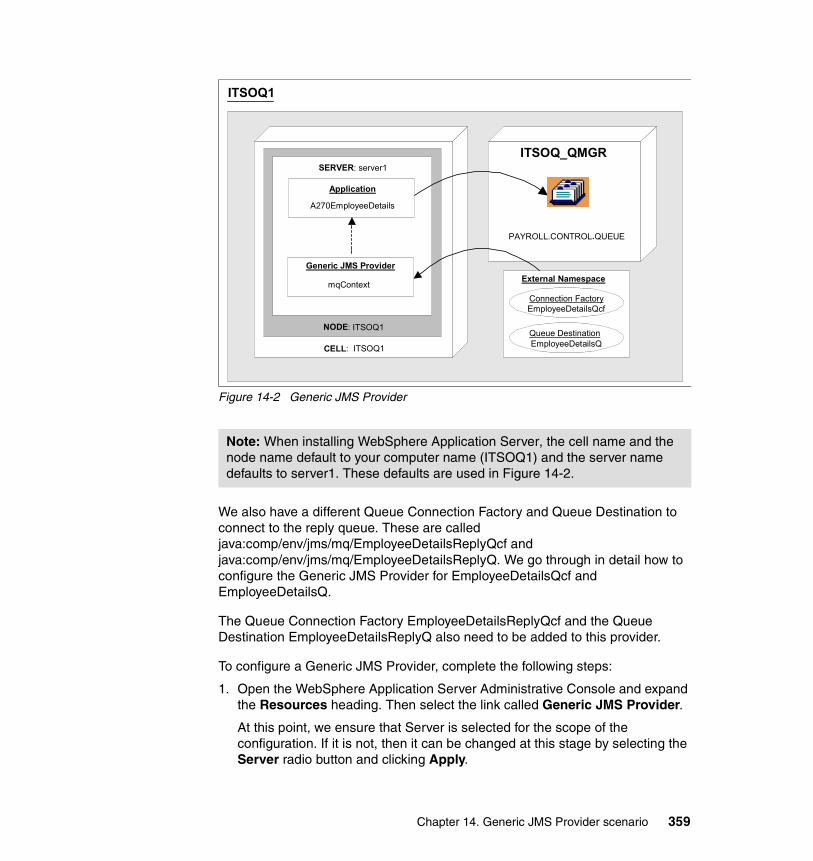
Figure 14-2 Generic JMS Provider
We also have a different Queue Connection Factory and Queue Destination to connect to the reply queue. These are called java:comp/env/jms/mq/EmployeeDetailsReplyQcf and java:comp/env/jms/mq/EmployeeDetailsReplyQ. We go through in detail how to configure the Generic JMS Provider for EmployeeDetailsQcf and EmployeeDetailsQ.
The Queue Connection Factory EmployeeDetailsReplyQcf and the Queue Destination EmployeeDetailsReplyQ also need to be added to this provider.
To configure a Generic JMS Provider, complete the following steps:
1. Open the WebSphere Application Server Administrative Console and expand the Resources heading. Then select the link called Generic JMS Provider.
At this point, we ensure that Server is selected for the scope of the configuration. If it is not, then it can be changed at this stage by selecting the Server radio button and clicking Apply.
Note: When installing WebSphere Application Server, the cell name and the node name default to your computer name (ITSOQ1) and the server name defaults to server1. These defaults are used in Figure 14-2.
ITSOQ1
ITSOQ_QMGR
NODE: ITSOQ1
CELL: ITSOQ1
SERVER: server1
Application
A270EmployeeDetails
External Namespace
Connection FactoryEmployeeDetailsQcf
Queue DestinationEmployeeDetailsQ
PAYROLL.CONTROL.QUEUE
Generic JMS Provider
mqContext
Chapter 14. Generic JMS Provider scenario 359
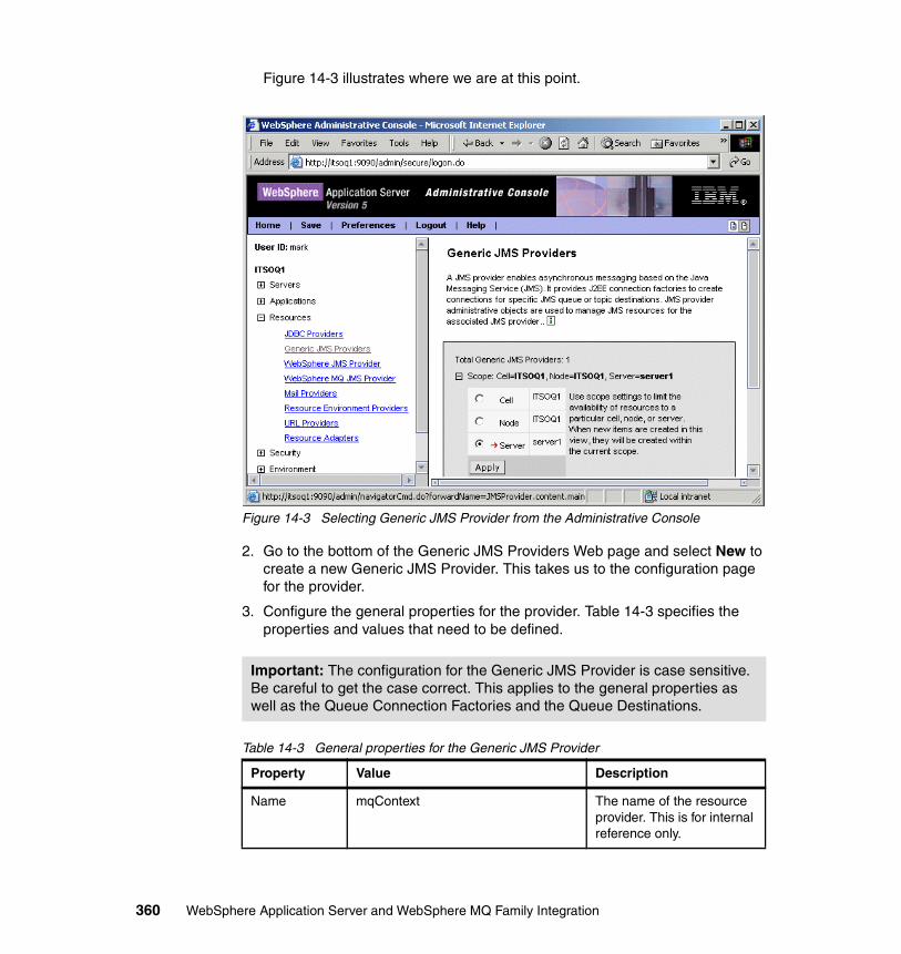
Figure 14-3 illustrates where we are at this point.
Figure 14-3 Selecting Generic JMS Provider from the Administrative Console
2. Go to the bottom of the Generic JMS Providers Web page and select New to create a new Generic JMS Provider. This takes us to the configuration page for the provider.
3. Configure the general properties for the provider. Table 14-3 specifies the properties and values that need to be defined.
Table 14-3 General properties for the Generic JMS Provider
Important: The configuration for the Generic JMS Provider is case sensitive. Be careful to get the case correct. This applies to the general properties as well as the Queue Connection Factories and the Queue Destinations.
Property Value Description
Name mqContext The name of the resource provider. This is for internal reference only.
360 WebSphere Application Server and WebSphere MQ Family Integration
Click Apply at the bottom of the General Properties page and save your configuration.
4. Go back to the General Properties page for the Generic JMS Provider we have just created. In the Additional Properties section at the bottom of the page, select the JMS Connection Factories link.
Once on the Generic JMS Connection Factories page, click New to create a new connection factory. This takes us to the configuration page where we enter the general properties. Table 14-4 specifies the properties and values that need to be defined.
Table 14-4 Queue Connection Factory properties for EmployeeDetailsQcf
Description MQSeries 5.2.1 Generic JMS Provider
Optional
Classpath C:\mq\Java\lib\com.ibm.mq.jarC:\mq\Java\lib\com.ibm.mqjms.jarC:\mq\Java\lib\jms.jarC:\mq\Java\lib\jndi.jarC:\mq\Java\lib\connector.jarC:\mq\Java\lib\fscontext.jarC:\mq\Java\lib\providerutil.jar
A list of paths or JAR file names that together form the location for the resource provider classes.These should match those provided in the setenv.bat batch file.Classpath entries are separated by using the Enter key and must not contain path separator characters (such as ';' or ':').
External Initial Context Factory
com.sun.jndi.fscontext.RefFSContextFactory
The Java classname of the initial context factory for the JMS provider. This will match the entry in JMSAdmin.config.
External Provider URL
file:/C:/JNDI-Directory/mq/ The JMS provider URL for external JNDI lookups. This will contain the URL entry in JMSAdmin.config plus the newly created context appended to the end.
Property Value Description
Name EmployeeDetailsQcf The required display name for the resource.
Property Value Description
Chapter 14. Generic JMS Provider scenario 361
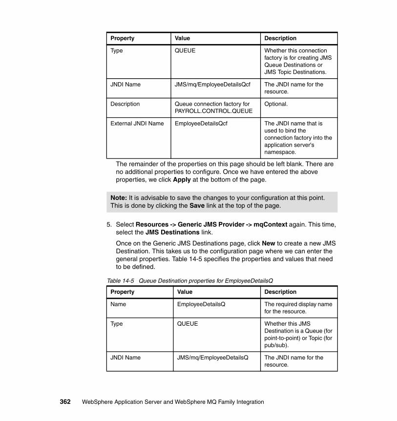
The remainder of the properties on this page should be left blank. There are no additional properties to configure. Once we have entered the above properties, we click Apply at the bottom of the page.
5. Select Resources -> Generic JMS Provider -> mqContext again. This time, select the JMS Destinations link.
Once on the Generic JMS Destinations page, click New to create a new JMS Destination. This takes us to the configuration page where we can enter the general properties. Table 14-5 specifies the properties and values that need to be defined.
Table 14-5 Queue Destination properties for EmployeeDetailsQ
Type QUEUE Whether this connection factory is for creating JMS Queue Destinations or JMS Topic Destinations.
JNDI Name JMS/mq/EmployeeDetailsQcf The JNDI name for the resource.
Description Queue connection factory for PAYROLL.CONTROL.QUEUE
Optional.
External JNDI Name EmployeeDetailsQcf The JNDI name that is used to bind the connection factory into the application server's namespace.
Note: It is advisable to save the changes to your configuration at this point. This is done by clicking the Save link at the top of the page.
Property Value Description
Name EmployeeDetailsQ The required display name for the resource.
Type QUEUE Whether this JMS Destination is a Queue (for point-to-point) or Topic (for pub/sub).
JNDI Name JMS/mq/EmployeeDetailsQ The JNDI name for the resource.
Property Value Description
362 WebSphere Application Server and WebSphere MQ Family Integration
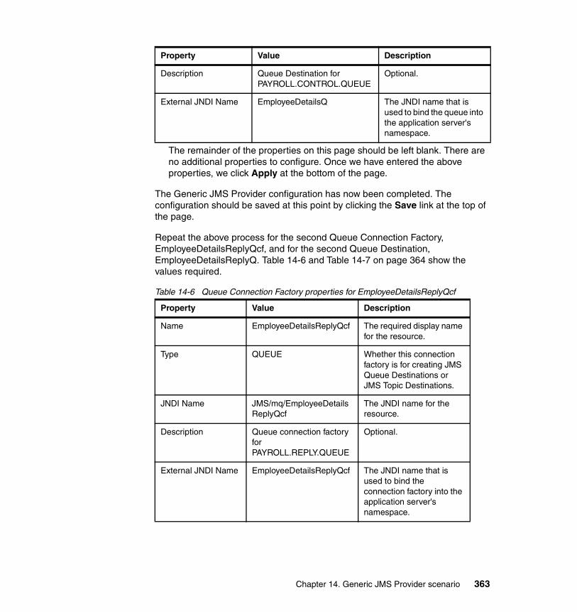
The remainder of the properties on this page should be left blank. There are no additional properties to configure. Once we have entered the above properties, we click Apply at the bottom of the page.
The Generic JMS Provider configuration has now been completed. The configuration should be saved at this point by clicking the Save link at the top of the page.
Repeat the above process for the second Queue Connection Factory, EmployeeDetailsReplyQcf, and for the second Queue Destination, EmployeeDetailsReplyQ. Table 14-6 and Table 14-7 on page 364 show the values required.
Table 14-6 Queue Connection Factory properties for EmployeeDetailsReplyQcf
Description Queue Destination for PAYROLL.CONTROL.QUEUE
Optional.
External JNDI Name EmployeeDetailsQ The JNDI name that is used to bind the queue into the application server's namespace.
Property Value Description
Name EmployeeDetailsReplyQcf The required display name for the resource.
Type QUEUE Whether this connection factory is for creating JMS Queue Destinations or JMS Topic Destinations.
JNDI Name JMS/mq/EmployeeDetailsReplyQcf
The JNDI name for the resource.
Description Queue connection factory for PAYROLL.REPLY.QUEUE
Optional.
External JNDI Name EmployeeDetailsReplyQcf The JNDI name that is used to bind the connection factory into the application server's namespace.
Property Value Description
Chapter 14. Generic JMS Provider scenario 363
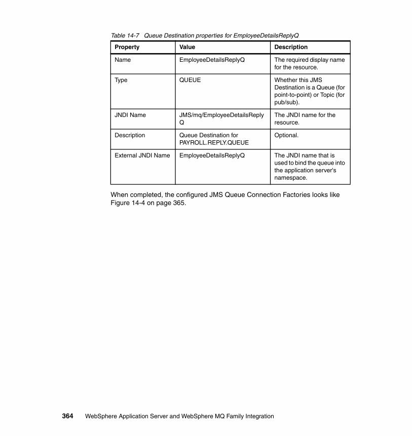
Table 14-7 Queue Destination properties for EmployeeDetailsReplyQ
When completed, the configured JMS Queue Connection Factories looks like Figure 14-4 on page 365.
Property Value Description
Name EmployeeDetailsReplyQ The required display name for the resource.
Type QUEUE Whether this JMS Destination is a Queue (for point-to-point) or Topic (for pub/sub).
JNDI Name JMS/mq/EmployeeDetailsReplyQ
The JNDI name for the resource.
Description Queue Destination for PAYROLL.REPLY.QUEUE
Optional.
External JNDI Name EmployeeDetailsReplyQ The JNDI name that is used to bind the queue into the application server's namespace.
364 WebSphere Application Server and WebSphere MQ Family Integration
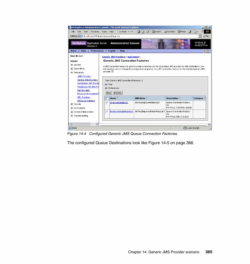
Figure 14-4 Configured Generic JMS Queue Connection Factories
The configured Queue Destinations look like Figure 14-5 on page 366.
Chapter 14. Generic JMS Provider scenario 365
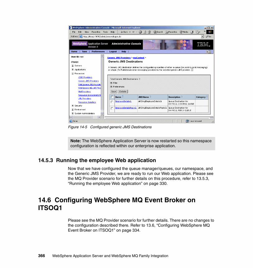
Figure 14-5 Configured generic JMS Destinations
14.5.3 Running the employee Web applicationNow that we have configured the queue manager/queues, our namespace, and the Generic JMS Provider, we are ready to run our Web application. Please see the MQ Provider scenario for further details on this procedure, refer to 13.5.3, “Running the employee Web application” on page 330.
14.6 Configuring WebSphere MQ Event Broker on ITSOQ1
Please see the MQ Provider scenario for further details. There are no changes to the configuration described there. Refer to 13.6, “Configuring WebSphere MQ Event Broker on ITSOQ1” on page 334.
Note: The WebSphere Application Server is now restarted so this namespace configuration is reflected within our enterprise application.
366 WebSphere Application Server and WebSphere MQ Family Integration
14.7 WebSphere MQ Integrator Broker configuration on ITSOM1
Please see the MQ Provider scenario for further details. There are no changes to the configuration described there. Refer to 13.7, “WebSphere MQ Integrator Broker configuration on ITSOM1” on page 339.
Chapter 14. Generic JMS Provider scenario 367

368 WebSphere Application Server and WebSphere MQ Family Integration
Chapter 15. WebSphere MQ and SSL scenario
In this chapter we provide a scenario that makes use of the WebSphere Application Server Generic JMS Provider. Recall that if you decide to encrypt the flow of messages between WebSphere Application Server and WebSphere MQ, you will need to use the Generic JMS Provider instead of the JMS MQ Provider.
Consider the situation where you have created an application based on Chapter 13, “WebSphere MQ Provider scenario” on page 315. The solution works successfully in a test environment. When you come to implement this in a production environment, your security personnel insist that the entire message flow needs to be encrypted because the messages contain confidential personnel information. This covers all data flowing in the following stages:
� Browser input� Servlet on WebSphere Application Server� Message input to WebSphere MQ Event Broker� Message flow to WebSphere MQ Integrator Broker� Message flow back to WebSphere MQ Event Broker� Confirmation message flow back to the browser
This scenario shows how we adapted our MQ Provider Scenario to make use of the Secure Sockets Layer (SSL) protocol for messages flowing anywhere within our application.
15
© Copyright IBM Corp. 2003. All rights reserved. 369
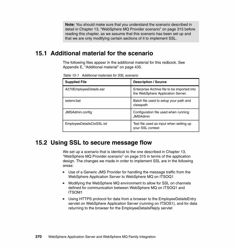
15.1 Additional material for the scenarioThe following files appear in the additional material for this redbook. See Appendix E, “Additional material” on page 435.
Table 15-1 Additional materials for SSL scenario
15.2 Using SSL to secure message flowWe set up a scenario that is identical to the one described in Chapter 13, “WebSphere MQ Provider scenario” on page 315 in terms of the application design. The changes we made in order to implement SSL are in the following areas:
� Use of a Generic JMS Provider for handling the message traffic from the WebSphere Application Server to WebSphere MQ on ITSOQ1
� Modifying the WebSphere MQ environment to allow for SSL on channels defined for communication between WebSphere MQ on ITSOQ1 and ITSOM1
� Using HTTPS protocol for data from a browser to the EmployeeDetailsEntry servlet on WebSphere Application Server (running on ITSOS1), and for data returning to the browser for the EmployeeDetailsReply servlet
Note: You should make sure that you understand the scenario described in detail in Chapter 13, “WebSphere MQ Provider scenario” on page 315 before reading this chapter, as we assume that this scenario has been set up and that we are only modifying certain sections of it to implement SSL.
Supplied File Description / Source
A270EmployeeDetails.ear Enterprise Archive file to be imported into the WebSphere Application Server.
setenv.bat Batch file used to setup your path and classpath
JMSAdmin.config Configuration file used when running JMSAdmin
EmployeeDetailsCtxSSL.txt Text file used as input when setting up your SSL context
370 WebSphere Application Server and WebSphere MQ Family Integration
15.2.1 Generic JMS ProviderWe needed to modify our scenario by changing the WebSphere Application Server resource setup. Where we previously specified that the JMS MQ Provider was to be used to handle the message traffic and to define the resources required to communicate with WebSphere MQ, we now had to define a Generic JMS Provider instead.
We describe this section in detail in “Generic JMS Provider configuration” on page 402.
15.2.2 Overview of SSLWe will provide a brief introduction to SSL and then describe how we implemented it in our scenario.
IntroductionSupport for SSL was introduced in WebSphere MQ with Version 5.3. SSL is an industry-standard protocol that allows you to secure the transport of message data across an insecure network. It provides security in the areas of data integrity, authentication and encryption.
Components of SSLWe will describe the components of SSL briefly. For more details please refer to WebSphere MQ Security, SC34-6079, or to WebSphere MQ Security in an Enterprise Environment, SG24-6814.
CertificatesA certificate is an digital entity that must be exchanged between two points of a transmission for authentication purposes. It is composed of a key and various other fields. These certificates may either be self-signed certificates (used for testing purposes) or certificates purchased from and issued by a Certificate Authority.
EncryptionSymmetric encryption is used when two partners each have access to the same secret certificate key; the challenge is how to share that key in a secure way. . Asymmetric encryption means that anyone using the public key of a certificate can decrypt a message sent by the owner of the private key. Symmetric is
Note: This procedure will only work on WebSphere MQ V5.3, as SSL support was only introduced in V5.3.
Chapter 15. WebSphere MQ and SSL scenario 371
quicker but more restricted, whereas asymmetric encryption is more generally used in WebSphere MQ applications. Basically, assymetric encryption allows secure exchange of a symmetric key.
HashingThis is a means whereby a number is produced representing the data being transferred. The numbers at both ends of the transmission can be compared, and if they do not agree it is likely that the message has been tampered with.
CipherSpecsA CipherSpec is a combination of an encryption algorithm and a hash function. It is specified on a channel level. Both ends of a channel definition need to specify the same SSLCipherSpec value for a secure channel operation.
Message integrityThis is ensured by the combination of an encryption algorithm and a hashing function.
15.2.3 Setting up certificates for SSLBefore we implement SSL in our environment we need to have certificates available for securing our message traffic. For the purposes of our test it was sufficient to use a self-signed certificate, which is almost like a ‘dummy’ certificate. In a production environment you would probably want to use a genuine certificate generated by a Certificate Authority such as VeriSign, for example, or you might have your own business’s Certificate Authority.
There are many ways to generate self-signed certificates, including the IBM Key Management Utility supplied with the IBM HTTP Server. (We installed the IBM HTTP Server as part of our installation of WebSphere Application Server V5.)
However we used the OpenSSL tool, which is part of the Cygwin toolset, and executed the following steps to generate a self-signed certificate.
Downloading the OpenSSL toolThis step downloads the OpenSSL tool to be used in step 2 to create the certificate:
1. Go to http://www.cygwin.com
2. From the Cygwin home page, click Install now!
3. Select an appropriate directory on the workstation to save the resulting setup.exe file
4. Double-click the setup.exe file that has just been downloaded.
372 WebSphere Application Server and WebSphere MQ Family Integration
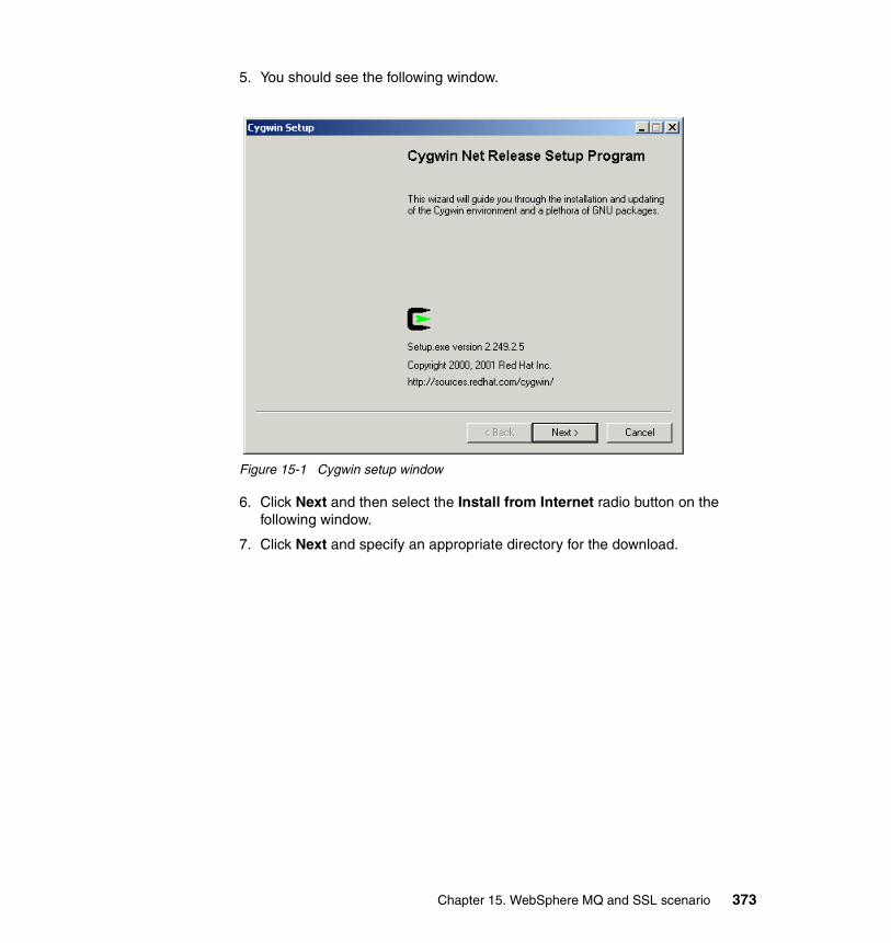
5. You should see the following window.
Figure 15-1 Cygwin setup window
6. Click Next and then select the Install from Internet radio button on the following window.
7. Click Next and specify an appropriate directory for the download.
Chapter 15. WebSphere MQ and SSL scenario 373
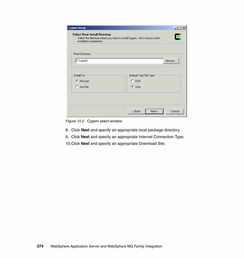
Figure 15-2 Cygwin select window
8. Click Next and specify an appropriate local package directory.
9. Click Next and specify an appropriate Internet Connection Type.
10.Click Next and specify an appropriate Download Site.
374 WebSphere Application Server and WebSphere MQ Family Integration
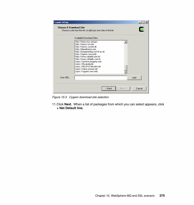
Figure 15-3 Cygwin download site selection
11.Click Next. When a list of packages from which you can select appears, click + Net Default line.
Chapter 15. WebSphere MQ and SSL scenario 375
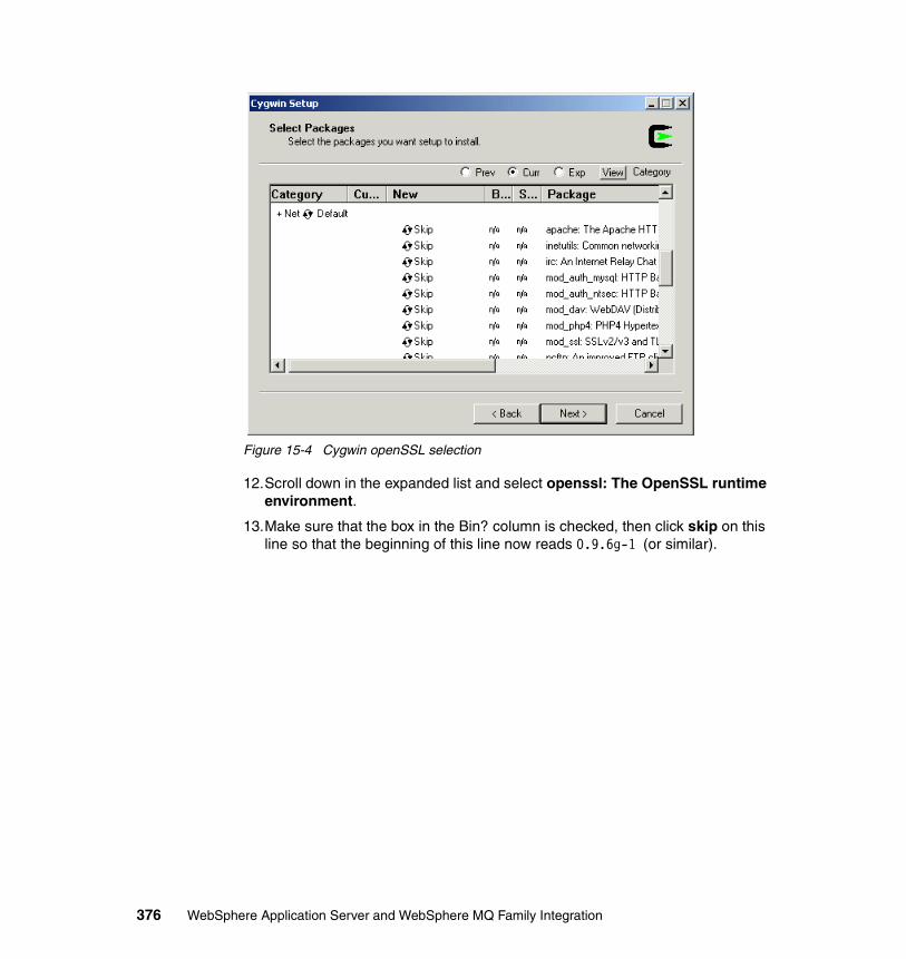
Figure 15-4 Cygwin openSSL selection
12.Scroll down in the expanded list and select openssl: The OpenSSL runtime environment.
13.Make sure that the box in the Bin? column is checked, then click skip on this line so that the beginning of this line now reads 0.9.6g-1 (or similar).
376 WebSphere Application Server and WebSphere MQ Family Integration
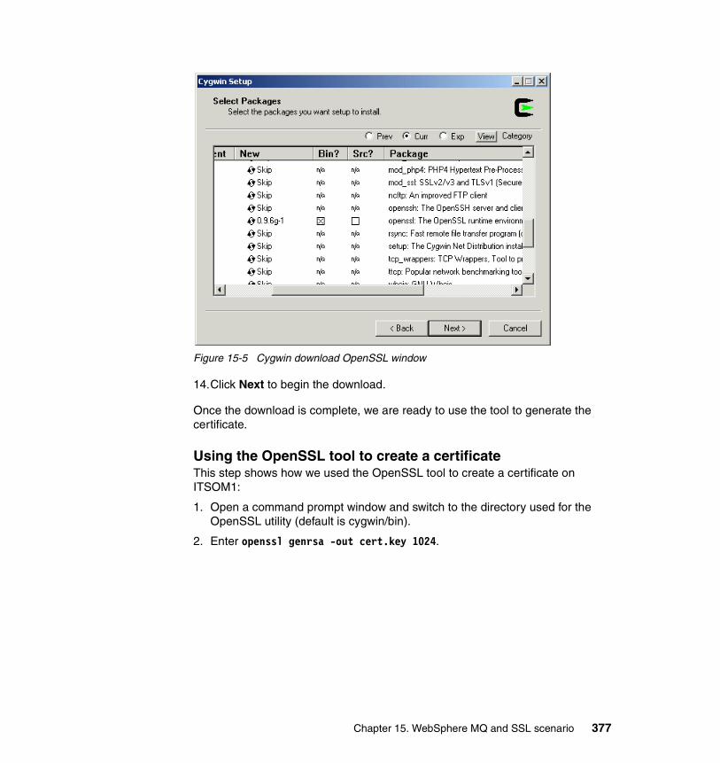
Figure 15-5 Cygwin download OpenSSL window
14.Click Next to begin the download.
Once the download is complete, we are ready to use the tool to generate the certificate.
Using the OpenSSL tool to create a certificateThis step shows how we used the OpenSSL tool to create a certificate on ITSOM1:
1. Open a command prompt window and switch to the directory used for the OpenSSL utility (default is cygwin/bin).
2. Enter openssl genrsa -out cert.key 1024.
Chapter 15. WebSphere MQ and SSL scenario 377
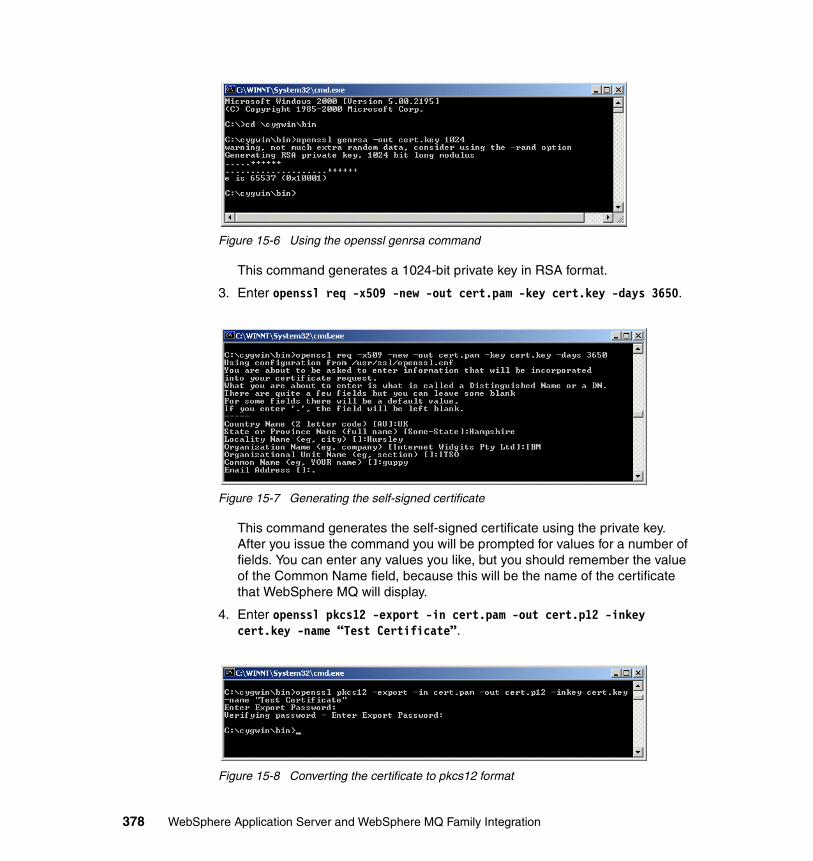
Figure 15-6 Using the openssl genrsa command
This command generates a 1024-bit private key in RSA format.
3. Enter openssl req -x509 -new -out cert.pam -key cert.key -days 3650.
Figure 15-7 Generating the self-signed certificate
This command generates the self-signed certificate using the private key. After you issue the command you will be prompted for values for a number of fields. You can enter any values you like, but you should remember the value of the Common Name field, because this will be the name of the certificate that WebSphere MQ will display.
4. Enter openssl pkcs12 -export -in cert.pam -out cert.p12 -inkey cert.key -name “Test Certificate”.
Figure 15-8 Converting the certificate to pkcs12 format
378 WebSphere Application Server and WebSphere MQ Family Integration
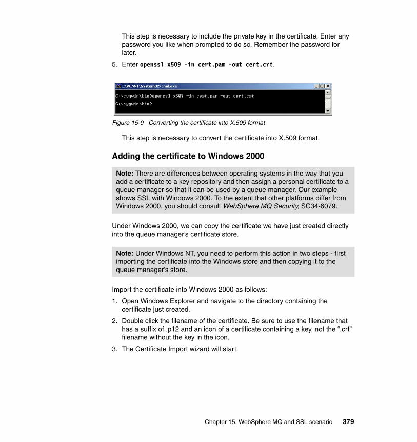
This step is necessary to include the private key in the certificate. Enter any password you like when prompted to do so. Remember the password for later.
5. Enter openssl x509 -in cert.pam -out cert.crt.
Figure 15-9 Converting the certificate into X.509 format
This step is necessary to convert the certificate into X.509 format.
Adding the certificate to Windows 2000
Under Windows 2000, we can copy the certificate we have just created directly into the queue manager’s certificate store.
Import the certificate into Windows 2000 as follows:
1. Open Windows Explorer and navigate to the directory containing the certificate just created.
2. Double click the filename of the certificate. Be sure to use the filename that has a suffix of .p12 and an icon of a certificate containing a key, not the “.crt” filename without the key in the icon.
3. The Certificate Import wizard will start.
Note: There are differences between operating systems in the way that you add a certificate to a key repository and then assign a personal certificate to a queue manager so that it can be used by a queue manager. Our example shows SSL with Windows 2000. To the extent that other platforms differ from Windows 2000, you should consult WebSphere MQ Security, SC34-6079.
Note: Under Windows NT, you need to perform this action in two steps - first importing the certificate into the Windows store and then copying it to the queue manager’s store.
Chapter 15. WebSphere MQ and SSL scenario 379
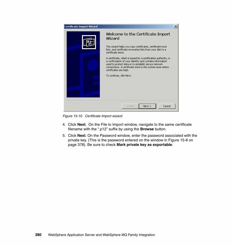
Figure 15-10 Certificate Import wizard
4. Click Next. On the File to Import window, navigate to the same certificate filename with the “.p12” suffix by using the Browse button.
5. Click Next. On the Password window, enter the password associated with the private key. (This is the password entered on the window in Figure 15-8 on page 378). Be sure to check Mark private key as exportable.
380 WebSphere Application Server and WebSphere MQ Family Integration
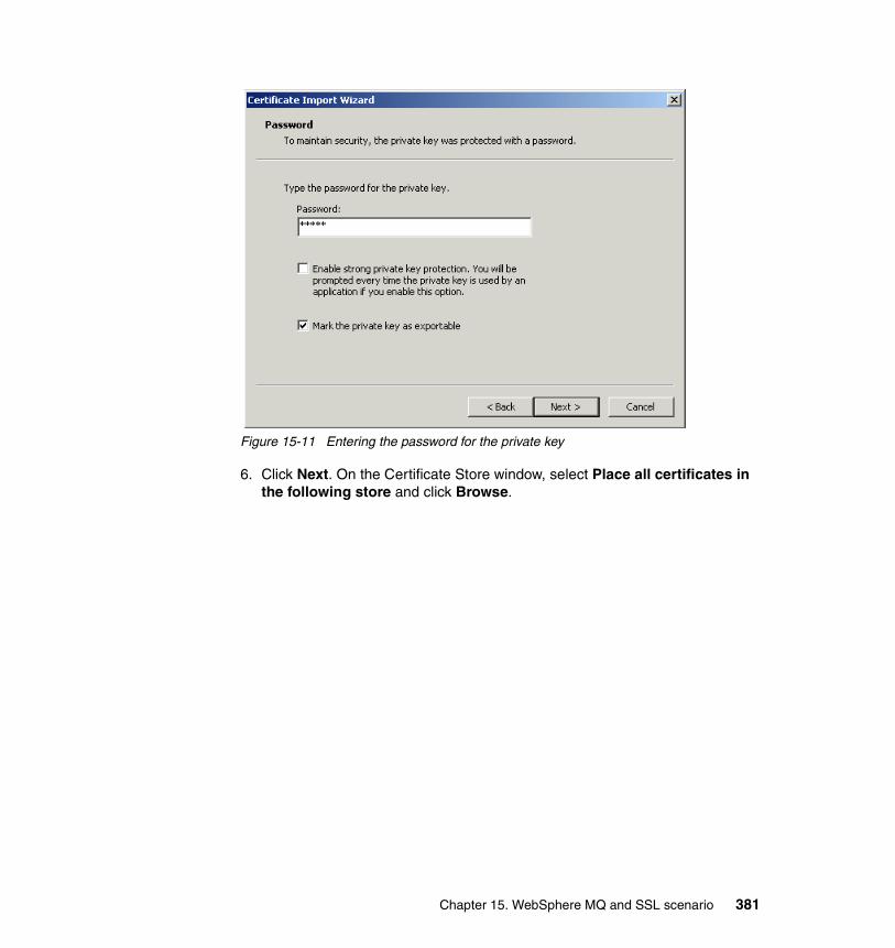
Figure 15-11 Entering the password for the private key
6. Click Next. On the Certificate Store window, select Place all certificates in the following store and click Browse.
Chapter 15. WebSphere MQ and SSL scenario 381
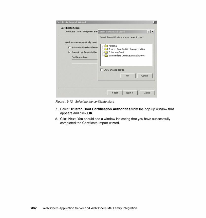
Figure 15-12 Selecting the certificate store
7. Select Trusted Root Certification Authorities from the pop-up window that appears and click OK.
8. Click Next. You should see a window indicating that you have successfully completed the Certificate Import wizard.
382 WebSphere Application Server and WebSphere MQ Family Integration
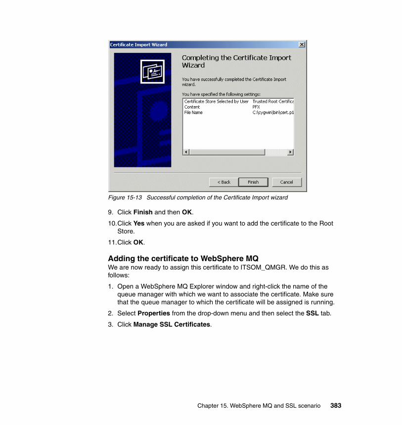
Figure 15-13 Successful completion of the Certificate Import wizard
9. Click Finish and then OK.
10.Click Yes when you are asked if you want to add the certificate to the Root Store.
11.Click OK.
Adding the certificate to WebSphere MQWe are now ready to assign this certificate to ITSOM_QMGR. We do this as follows:
1. Open a WebSphere MQ Explorer window and right-click the name of the queue manager with which we want to associate the certificate. Make sure that the queue manager to which the certificate will be assigned is running.
2. Select Properties from the drop-down menu and then select the SSL tab.
3. Click Manage SSL Certificates.
Chapter 15. WebSphere MQ and SSL scenario 383
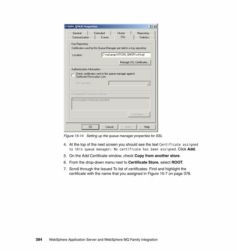
Figure 15-14 Setting up the queue manager properties for SSL
4. At the top of the next screen you should see the text Certificate assigned to this queue manager: No certificate has been assigned. Click Add.
5. On the Add Certificate window, check Copy from another store.
6. From the drop-down menu next to Certificate Store, select ROOT.
7. Scroll through the Issued To list of certificates. Find and highlight the certificate with the name that you assigned in Figure 15-7 on page 378.
384 WebSphere Application Server and WebSphere MQ Family Integration
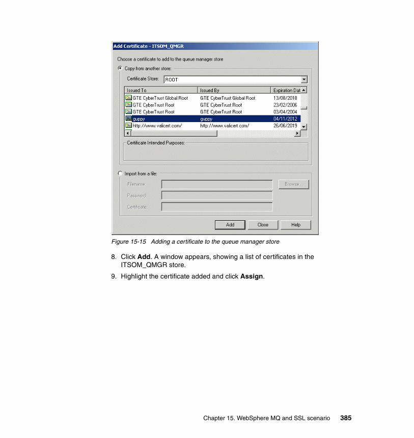
Figure 15-15 Adding a certificate to the queue manager store
8. Click Add. A window appears, showing a list of certificates in the ITSOM_QMGR store.
9. Highlight the certificate added and click Assign.
Chapter 15. WebSphere MQ and SSL scenario 385
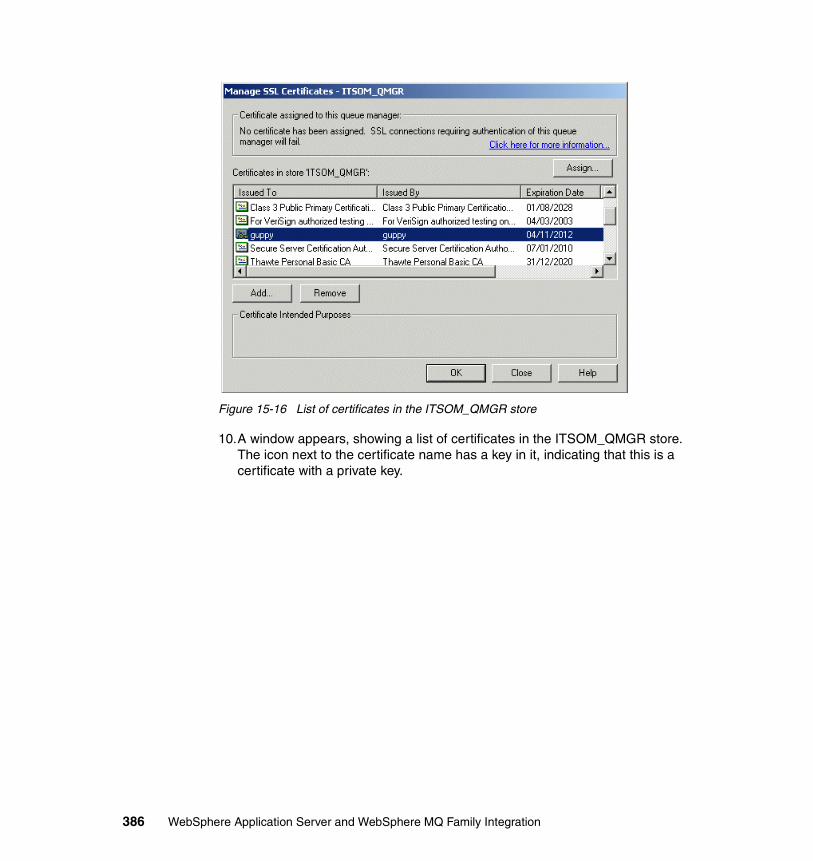
Figure 15-16 List of certificates in the ITSOM_QMGR store
10.A window appears, showing a list of certificates in the ITSOM_QMGR store. The icon next to the certificate name has a key in it, indicating that this is a certificate with a private key.
386 WebSphere Application Server and WebSphere MQ Family Integration
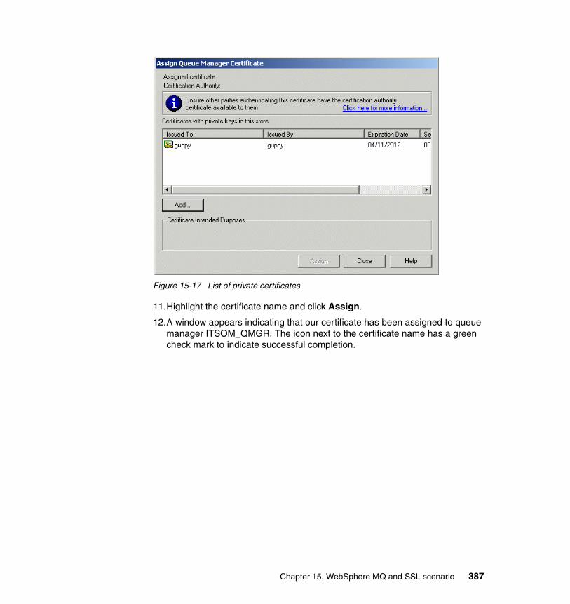
Figure 15-17 List of private certificates
11.Highlight the certificate name and click Assign.
12.A window appears indicating that our certificate has been assigned to queue manager ITSOM_QMGR. The icon next to the certificate name has a green check mark to indicate successful completion.
Chapter 15. WebSphere MQ and SSL scenario 387
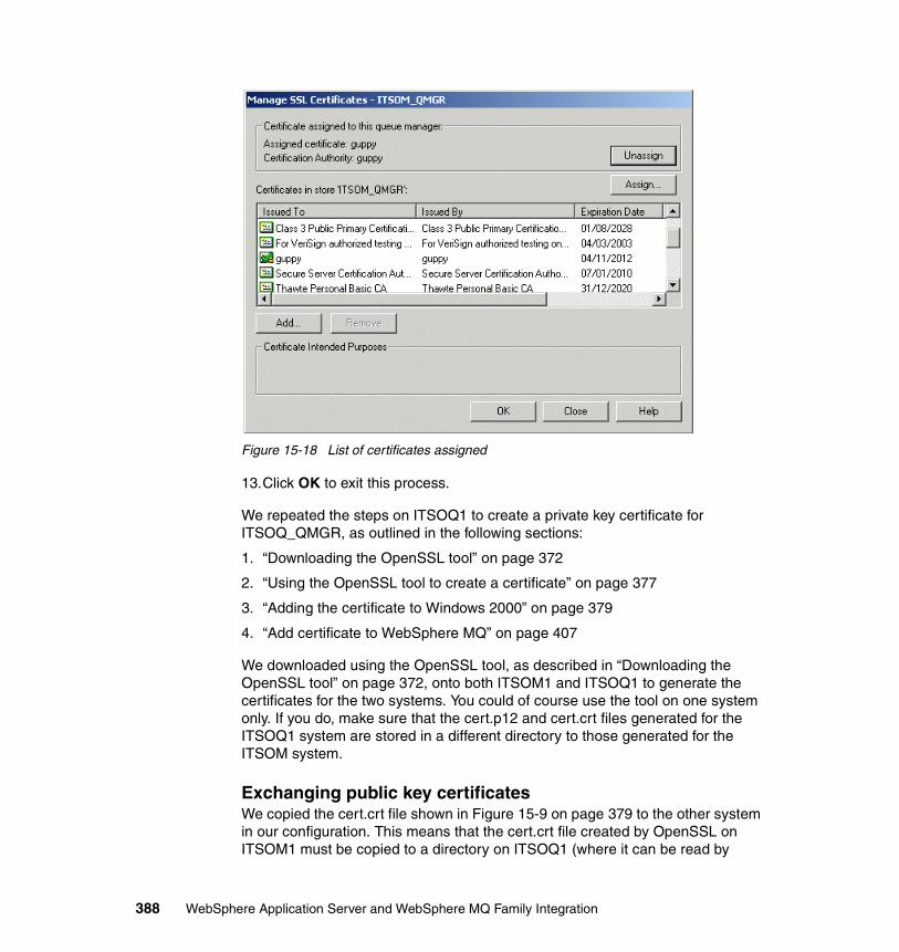
Figure 15-18 List of certificates assigned
13.Click OK to exit this process.
We repeated the steps on ITSOQ1 to create a private key certificate for ITSOQ_QMGR, as outlined in the following sections:
1. “Downloading the OpenSSL tool” on page 372
2. “Using the OpenSSL tool to create a certificate” on page 377
3. “Adding the certificate to Windows 2000” on page 379
4. “Add certificate to WebSphere MQ” on page 407
We downloaded using the OpenSSL tool, as described in “Downloading the OpenSSL tool” on page 372, onto both ITSOM1 and ITSOQ1 to generate the certificates for the two systems. You could of course use the tool on one system only. If you do, make sure that the cert.p12 and cert.crt files generated for the ITSOQ1 system are stored in a different directory to those generated for the ITSOM system.
Exchanging public key certificatesWe copied the cert.crt file shown in Figure 15-9 on page 379 to the other system in our configuration. This means that the cert.crt file created by OpenSSL on ITSOM1 must be copied to a directory on ITSOQ1 (where it can be read by
388 WebSphere Application Server and WebSphere MQ Family Integration
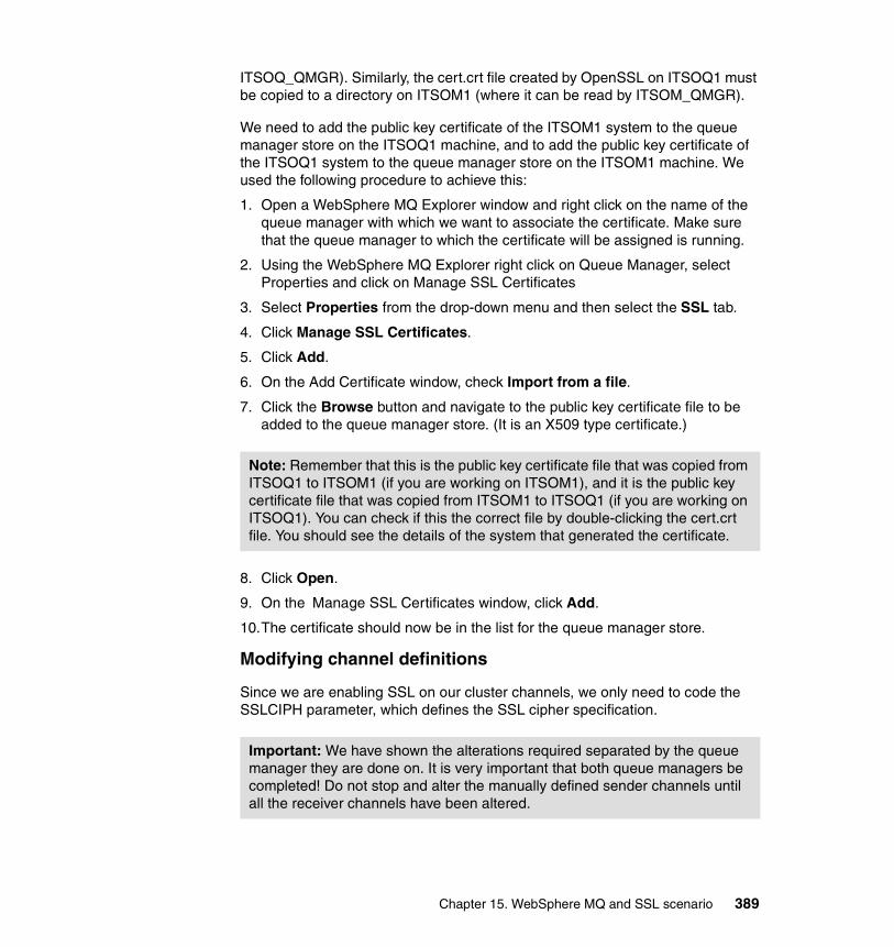
ITSOQ_QMGR). Similarly, the cert.crt file created by OpenSSL on ITSOQ1 must be copied to a directory on ITSOM1 (where it can be read by ITSOM_QMGR).
We need to add the public key certificate of the ITSOM1 system to the queue manager store on the ITSOQ1 machine, and to add the public key certificate of the ITSOQ1 system to the queue manager store on the ITSOM1 machine. We used the following procedure to achieve this:
1. Open a WebSphere MQ Explorer window and right click on the name of the queue manager with which we want to associate the certificate. Make sure that the queue manager to which the certificate will be assigned is running.
2. Using the WebSphere MQ Explorer right click on Queue Manager, select Properties and click on Manage SSL Certificates
3. Select Properties from the drop-down menu and then select the SSL tab.
4. Click Manage SSL Certificates.
5. Click Add.
6. On the Add Certificate window, check Import from a file.
7. Click the Browse button and navigate to the public key certificate file to be added to the queue manager store. (It is an X509 type certificate.)
8. Click Open.
9. On the Manage SSL Certificates window, click Add.
10.The certificate should now be in the list for the queue manager store.
Modifying channel definitions
Since we are enabling SSL on our cluster channels, we only need to code the SSLCIPH parameter, which defines the SSL cipher specification.
Note: Remember that this is the public key certificate file that was copied from ITSOQ1 to ITSOM1 (if you are working on ITSOM1), and it is the public key certificate file that was copied from ITSOM1 to ITSOQ1 (if you are working on ITSOQ1). You can check if this the correct file by double-clicking the cert.crt file. You should see the details of the system that generated the certificate.
Important: We have shown the alterations required separated by the queue manager they are done on. It is very important that both queue managers be completed! Do not stop and alter the manually defined sender channels until all the receiver channels have been altered.
Chapter 15. WebSphere MQ and SSL scenario 389
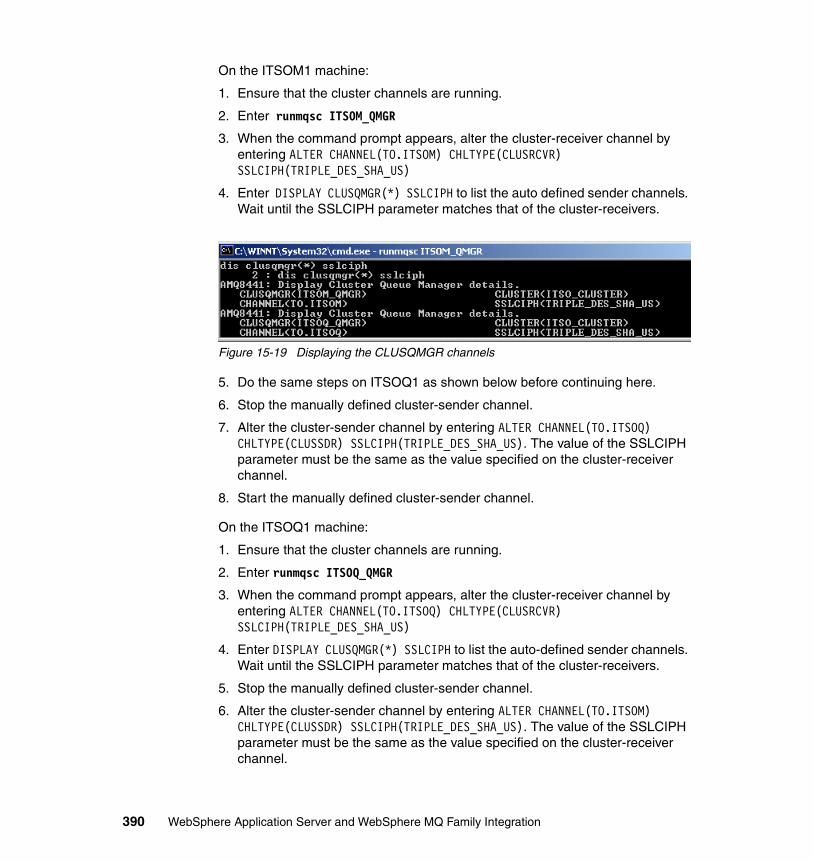
On the ITSOM1 machine:
1. Ensure that the cluster channels are running.
2. Enter runmqsc ITSOM_QMGR
3. When the command prompt appears, alter the cluster-receiver channel by entering ALTER CHANNEL(TO.ITSOM) CHLTYPE(CLUSRCVR) SSLCIPH(TRIPLE_DES_SHA_US)
4. Enter DISPLAY CLUSQMGR(*) SSLCIPH to list the auto defined sender channels. Wait until the SSLCIPH parameter matches that of the cluster-receivers.
Figure 15-19 Displaying the CLUSQMGR channels
5. Do the same steps on ITSOQ1 as shown below before continuing here.
6. Stop the manually defined cluster-sender channel.
7. Alter the cluster-sender channel by entering ALTER CHANNEL(TO.ITSOQ) CHLTYPE(CLUSSDR) SSLCIPH(TRIPLE_DES_SHA_US). The value of the SSLCIPH parameter must be the same as the value specified on the cluster-receiver channel.
8. Start the manually defined cluster-sender channel.
On the ITSOQ1 machine:
1. Ensure that the cluster channels are running.
2. Enter runmqsc ITSOQ_QMGR
3. When the command prompt appears, alter the cluster-receiver channel by entering ALTER CHANNEL(TO.ITSOQ) CHLTYPE(CLUSRCVR) SSLCIPH(TRIPLE_DES_SHA_US)
4. Enter DISPLAY CLUSQMGR(*) SSLCIPH to list the auto-defined sender channels. Wait until the SSLCIPH parameter matches that of the cluster-receivers.
5. Stop the manually defined cluster-sender channel.
6. Alter the cluster-sender channel by entering ALTER CHANNEL(TO.ITSOM) CHLTYPE(CLUSSDR) SSLCIPH(TRIPLE_DES_SHA_US). The value of the SSLCIPH parameter must be the same as the value specified on the cluster-receiver channel.
390 WebSphere Application Server and WebSphere MQ Family Integration
7. Start the manually defined cluster-sender channel.
15.2.4 Using HTTPS protocol with the browserIn order to secure the flow of data from and to a browser using SSL, we had to change the way in which a browser communicates with the servlet running on WebSphere Application Server. We did this in two different ways:
1. Creating a new SSL configuration and assigning it to a port that is already defined to WebSphere Application Server
2. Creating a new SSL configuration and assigning it to a new port in WebSphere Application Server
Using an existing port on WebSphere Application ServerWe completed the following steps to allow a browser to use a port already defined to WebSphere Application Server:
1. Define a new SSL configuration as follows:
a. Open the WebSphere Application Server Administrative Console and expand the Security heading. Then select the SSL link.
b. In the right-hand pane, click New to create a new SSL configuration.
c. Enter SSL_ITSOS1 as the name for the configuration next to Alias.
d. In the Key File Name field, enter C:\keystore\cert.p12
e. In the Key File Password field, enter the password entered on the window in Figure 15-8 on page 378).
f. Select PKCS12 from the Key File Format drop-down menu.
g. In the Trust File Name field, enter C:\truststore.
h. In the Trust File Password field, enterf keystore.
i. Leave the Trust File Format as JKS.
Note: The key file and trust file names and paths entered in the steps above must exactly match the names and paths used when the files were created using the OpenSSL keytool utility.
Chapter 15. WebSphere MQ and SSL scenario 391
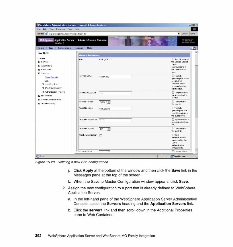
Figure 15-20 Defining a new SSL configuration
j. Click Apply at the bottom of the window and then click the Save link in the Messages pane at the top of the screen.
k. When the Save to Master Configuration window appears, click Save.
2. Assign the new configuration to a port that is already defined to WebSphere Application Server:
a. In the left-hand pane of the WebSphere Application Server Administrative Console, select the Servers heading and the Application Servers link.
b. Click the server1 link and then scroll down in the Additional Properties pane to Web Container.
392 WebSphere Application Server and WebSphere MQ Family Integration
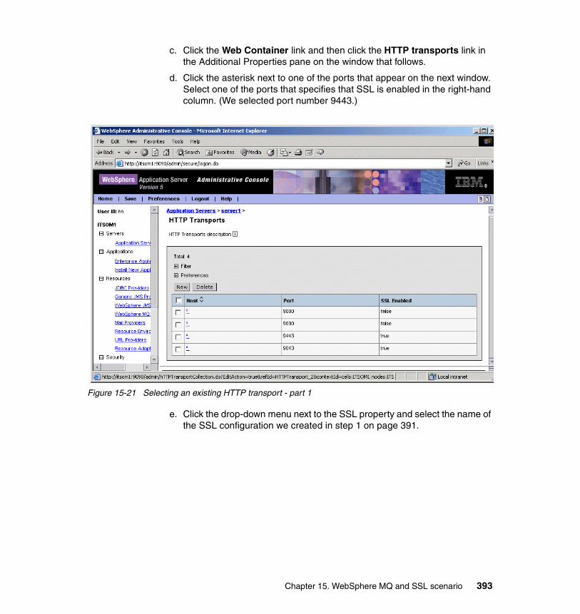
c. Click the Web Container link and then click the HTTP transports link in the Additional Properties pane on the window that follows.
d. Click the asterisk next to one of the ports that appear on the next window. Select one of the ports that specifies that SSL is enabled in the right-hand column. (We selected port number 9443.)
Figure 15-21 Selecting an existing HTTP transport - part 1
e. Click the drop-down menu next to the SSL property and select the name of the SSL configuration we created in step 1 on page 391.
Chapter 15. WebSphere MQ and SSL scenario 393
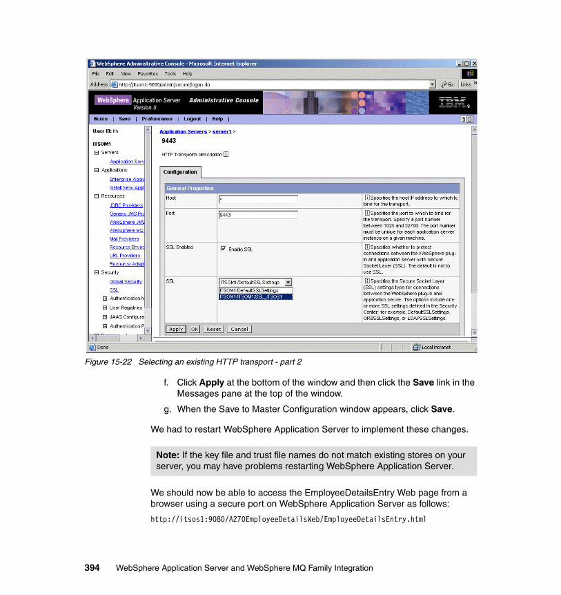
Figure 15-22 Selecting an existing HTTP transport - part 2
f. Click Apply at the bottom of the window and then click the Save link in the Messages pane at the top of the window.
g. When the Save to Master Configuration window appears, click Save.
We had to restart WebSphere Application Server to implement these changes.
We should now be able to access the EmployeeDetailsEntry Web page from a browser using a secure port on WebSphere Application Server as follows:
http://itsos1:9080/A270EmployeeDetailsWeb/EmployeeDetailsEntry.html
Note: If the key file and trust file names do not match existing stores on your server, you may have problems restarting WebSphere Application Server.
394 WebSphere Application Server and WebSphere MQ Family Integration
Using a new port on WebSphere Application ServerWe completed the following steps to allow a browser to use a new port on WebSphere Application Server:
1. Define a new SSL configuration in exactly the same manner as described in step 1 in “Using an existing port on WebSphere Application Server” on page 391.
2. Assign the new configuration to a new port in WebSphere Application Server. We did this by first defining a new host alias for our default_host:
a. In the left-hand pane of the WebSphere Application Server Administrative Console expand the Environment heading. Then select the Virtual Hosts link.
b. Click the default_host link and then scroll down in the Additional Properties pane to Host Aliases.
c. Click the Host Aliases link and then click New on the window that follows.
Chapter 15. WebSphere MQ and SSL scenario 395
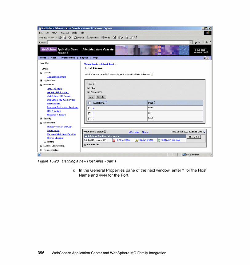
Figure 15-23 Defining a new Host Alias - part 1
d. In the General Properties pane of the next window, enter * for the Host Name and 4444 for the Port.
396 WebSphere Application Server and WebSphere MQ Family Integration
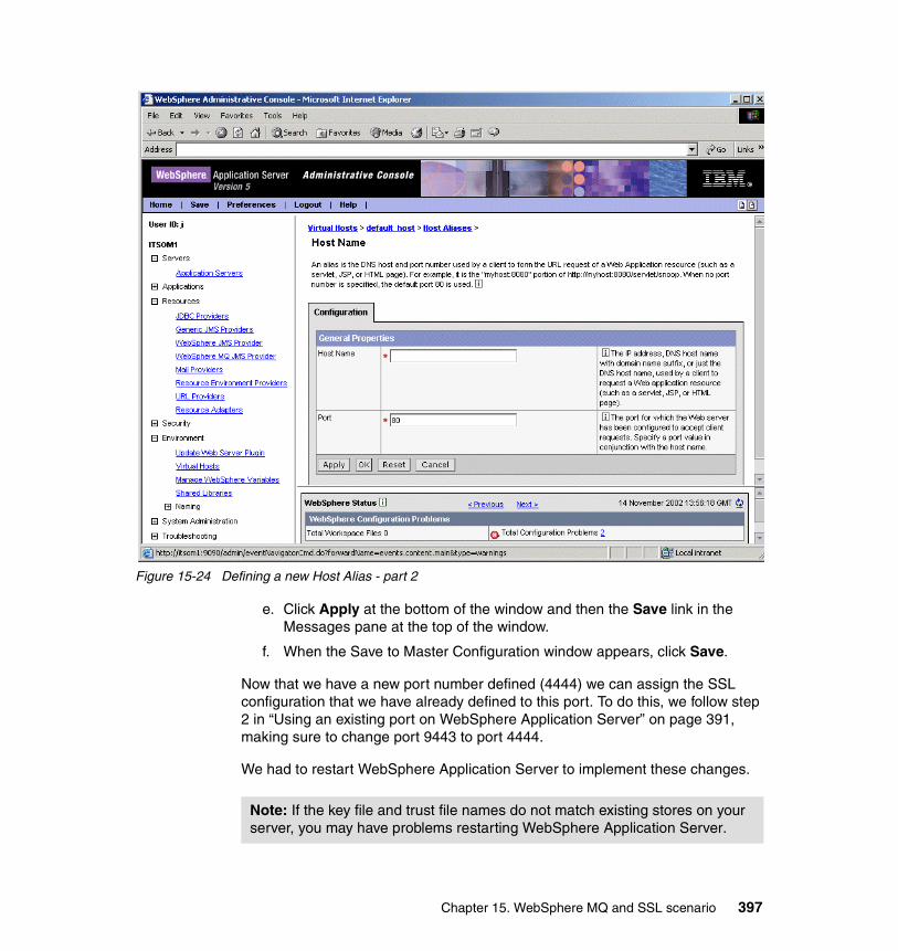
Figure 15-24 Defining a new Host Alias - part 2
e. Click Apply at the bottom of the window and then the Save link in the Messages pane at the top of the window.
f. When the Save to Master Configuration window appears, click Save.
Now that we have a new port number defined (4444) we can assign the SSL configuration that we have already defined to this port. To do this, we follow step 2 in “Using an existing port on WebSphere Application Server” on page 391, making sure to change port 9443 to port 4444.
We had to restart WebSphere Application Server to implement these changes.
Note: If the key file and trust file names do not match existing stores on your server, you may have problems restarting WebSphere Application Server.
Chapter 15. WebSphere MQ and SSL scenario 397
We should now be able to access the EmployeeDetailsEntry web page from a browser using a secure port on WebSphere Application Server as follows:
http://itsos1:4444/A270EmployeeDetailsWeb/EmployeeDetailsEntry.html
15.3 WebSphere Application Server to WebSphere MQ via SSL
In this section we describe the process to enable an SSL connection between WebSphere Application Server V5 and WebSphere MQ V5.3.1. In the MQ Provider scenario, we implemented a solution where both WebSphere Application Server and WebSphere MQ were on the same platform. But in a more realistic deployment, it would be quite legitimate to install WebSphere Application Server on its own server and communicate to WebSphere MQ on another server using an MQ Client connection. In this case it would also be quite legitimate to want to secure that connection with SSL.
This implementation involves installing a certificate on both platforms and swapping public keys. The public key is made available to each server by adding it to their respective trust stores. The connection between WebSphere Application Server and WebSphere MQ will be established by defining a Generic JMS Provider and setting up our JMS namespace externally. The MQ Client connection to WebSphere MQ will be made possible by the use of a server connection channel.
As we are modifying the original MQ Provider scenario, where WebSphere Application Server and WebSphere MQ have been installed on the same platform, we will use another WebSphere Application Server installation on another platform for this part of the SSL scenario. For this scenario we have labeled the platform running WebSphere Application Server ITSOS1. (The name of the original platform running WebSphere MQ remains ITSOQ1.)
This scenario is illustrated in the diagram in Figure 15-25 on page 399.
Important: If using another WebSphere Application Server, remember to install the supplied application A270EmployeeDetails.ear.
398 WebSphere Application Server and WebSphere MQ Family Integration
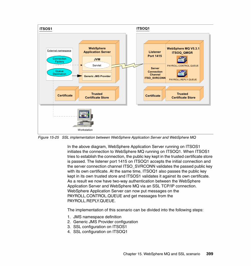
Figure 15-25 SSL implementation between WebSphere Application Server and WebSphere MQ
In the above diagram, WebSphere Application Server running on ITSOS1 initiates the connection to WebSphere MQ running on ITSOQ1. When ITSOS1 tries to establish the connection, the public key kept in the trusted certificate store is passed. The listener port 1415 on ITSOQ1 accepts the initial connection and the server connection channel ITSO_SVRCONN validates the passed public key with its own certificate. At the same time, ITSOQ1 also passes the public key kept in its own trusted store and ITSOS1 validates it against its own certificate. As a result we now have two-way authentication between the WebSphere Application Server and WebSphere MQ via an SSL TCP/IP connection. WebSphere Application Server can now put messages on the PAYROLL.CONTROL.QUEUE and get messages from the PAYROLL.REPLY.QUEUE.
The implementation of this scenario can be divided into the following steps:
1. JMS namespace definition2. Generic JMS Provider configuration3. SSL configuration on ITSOS14. SSL configuration on ITSOQ1
ITSOS1
WebSphereApplication Server
TrustedCertificate Store
Workstation
Certificate
ITSOQ1
TrustedCertificate StoreCertificate
WebSphere MQ V5.3.1ITSOQ_QMGR
PAYROLL.CONTROL.QUEUE
JVM
Servlet
PAYROLL.REPLY.QUEUE
ListenerPort 1415
ServerConnection
ChannelITSO_SVRCONN
Queue Destination
Connection Factory
External namespace
Generic JMS Provider
Chapter 15. WebSphere MQ and SSL scenario 399
15.3.1 JMS namespace definitionAs in the Generic JMS Provider scenario, we will be defining our JMS namespace by using the JMSAdmin tool that comes with WebSphere MQ V5.3.1. In previous versions of MQSeries, this administration tool was only available by installing the MA88 SupportPac (MQSeries classes for Java and MQSeries classes for JMS). The JMSAdmin tool can be found in the install_dir\java\bin directory.
The administration tool has a command-line interface. We can use this interactively, or use it to start a batch process. To create our namespace object, we will use the tool to start a batch process. But before we can do this, we must ensure the tool will successfully run in the interactive mode. The interactive mode provides a command prompt where you can enter administrative commands. In the batch mode, the command to start the tool includes the name of a file that contains an administration command script. In the additional material for this redbook, we have supplied a file that contains the command script.
The JMSAdmin tool requires a configuration file to run. By default, this file is called the same name, JMSAdmin.config. In this file, we specify what provider we want to use to create our namespace. A sample JMSAdmin.config file has also been included in the additional material. For this scenario, we decided to define our namespace in a file system. This is because we wanted to make our namespace persistent as opposed to the other types of providers, which are non-persistent. In this scenario, we found that the WebSphere Application Server may need to be restarted and if a non-persistent provider was being used, we would lose our namespace at this point.
We have broken down this process into three steps to help alleviate any problems using this tool. The steps are:
1. Configuring our environment2. Running JMSAdmin3. Creating our namespace objects
To configure the correct environment to run JMSAdmin, follow the steps in 14.4.1, “Environment configuration” on page 354.
To check to see if JMSAdmin will run in interactive mode, refer to 14.4.2, “Running JMSAdmin” on page 356.
Once we are able to run JMSAdmin, we can create all of our required namespace objects. To do this, we are going to run the JMSAdmin tool in batch mode. All the commands to create our namespace are supplied in a file called EmployeeDetailsCtxSSL.txt, which can be found in the additional material for this chapter. The commands create a context called mqSSL, create Queue Connection Factories for EmployeeDetailsQcf and EmployeeDetailsReplyQcf,
400 WebSphere Application Server and WebSphere MQ Family Integration
and create Queue Destinations for EmployeeDetailsQ and EmployeeDetailsReplyQ. The commands also specify the transport as client, supply the connection properties, and set the sslciphersuite to TRIPPLE_DES_SHU_US, which enables SSL.
There are a variety of different symmetric key encryption algorithms to use, and also several hash functions. The combination of these two algorithms is known as a CipherSpec and is negotiated as part of the handshake that creates a secure session using SSL. There are a number of CipherSpecs that are available to be used. We decided to always use TRIPLE_DES_SHU_US for this scenario to lower the chance of a different CipherSpec being used at each end of the connection (which will prevent the connection from being established).
The contents of this supplied file is shown in Example 15-1.
Example 15-1 EmployeeDetailsCtxSSL.txt
def ctx(mqSSL)chg ctx(mqSSL)def wsqcf(EmployeeDetailsQcf) +
transport(CLIENT) +hostname(ITSOQ1) +port(1415) +qmgr(ITSOQ_QMGR) +channel(ITSO_SVRCONN) +sslciphersuite(TRIPLE_DES_SHA_US)
def wsqcf(EmployeeDetailsReplyQcf) +transport(CLIENT) +hostname(ITSOQ1) +port(1415) +qmgr(ITSOQ_QMGR) +channel(ITSO_SVRCONN) +sslciphersuite(TRIPLE_DES_SHA_US)
def q(EmployeeDetailsQ) queue(PAYROLL.CONTROL.QUEUE)def q(EmployeeDetailsReplyQ) queue(PAYROLL.REPLY.QUEUE)end
To run JMSAdmin in batch mode with this input file, enter the following command:
JMSAdmin < EmployeeDetailsCtxSSL.txt
If the tool successfully creates the context and all of the objects, the resulting output will resemble Example 15-2.
Example 15-2 JMSAdmin SSL output
5648-C60, 5724-B41, 5655-F10 (c) Copyright IBM Corp. 2002. All Rights Reserved.Starting Websphere MQ classes for Java(tm) Message Service Administration
Chapter 15. WebSphere MQ and SSL scenario 401
InitCtx>InitCtx>InitCtx/mqSSL> WARNING: Converting CipherSpec TRIPLE_DES_SHA_US to CipherSuite SSL_RSA_WITH_3DES_EDE_CBC_SHA
InitCtx/mqSSL> WARNING: Converting CipherSpec TRIPLE_DES_SHA_US to CipherSuite SSL_RSA_WITH_3DES_EDE_CBC_SHA
InitCtx/mqSSL>InitCtx/mqSSL>InitCtx/mqSSL>Stopping Websphere MQ classes for Java(tm) Message Service Administration
The warnings in the resulting output only indicate that the tool is converting the CipherSpec to its own version or representation of the one specified, which is acceptable. A CipherSpec of TRIPLE_DES_SHU_US can still be defined at the other end of the connection and handshaking will still take place.
At this point we have completed the JMS namespace definition and we can proceed to the configuration of the Generic JMS Provider that will connect this namespace the applications running in the WebSphere Application Server.
15.3.2 Generic JMS Provider configurationThe Generic JMS Provider is the link between the application and the external JMS namespace, which in turn provides the details to connect to WebSphere MQ via SSL. In the supplied example application, A270EmployeeDetails, we define the Queue Connection Factory as java:comp/env/jms/mq/EmployeeDetailsQcf and define the Queue Destination as java:comp/env/jms/mq/EmployeeDetailsQ. The Generic JMS Provider uses these internal JNDI names and links them to the external JNDI names defined in our JMS namespace.
The configuration of the Generic JMS Provider is exactly the same as in the Generic JMS Provider scenario, except for one alteration to the configuration. In the above definition of our JMS namespace, we have defined our context as mqSSL, while in the Generic JMS Provider scenario we defined our context as mq. Therefore in the general properties for the Generic JMS Provider, we need to define the External Provider URL as:
file:/C:/JNDI-Directory/mqSSL/
The remainder of the configuration should be followed as described in 14.5.2, “Configuring the Generic JMS Provider” on page 358.
402 WebSphere Application Server and WebSphere MQ Family Integration
15.3.3 SSL configuration on ITSOS1In this section we will describe the SSL configuration on the server running WebSphere Application Server (ITSOS1).
This section can be divided into the following steps:
1. Create a private key certificate and place it in a keystore
2. Create a public key certificate that can be exported to WebSphere MQ on ITSOQ1
3. Create a truststore that will contain the public key that has been imported from ITSOQ1
4. Add both the key store and trust store to the JVM (Java Virtual Machine) within WebSphere Application Server
Create private keyIn this step we use a tool called keytool which is part of the Java runtime environment from Version 1.2 upwards. By using certain parameters with keytool, we can create both a key store to store our own certificate and private key, and a trust store to store any public keys that are required to connect to other platforms.
To create a private key and associated certificate in a Java key store, use the following command:
keytool -genkey -alias clientcert -keystore keystore -keyalg RSA
where clientcert is the name of your private key, keystore is the name of the store and RSA is the encryption algorithm to use.
The above command generates a key pair and wraps the public key into a self-signed certificate. When entering the command, we will be prompted for a key store password, which will be required when the key store is used. We will also be prompted for the certificate’s Distinguished Name. It does not matter what is entered at this point. Finally we will be asked if we want the same password as the key store. We should answer Yes to this question.
Note: If the java_install\jre\bin directory is not in your path, the complete path will be required when running keytool.exe. The key store should be created in the location it will be used from and not copied there after it has been created. Either run the above command in the required directory or fully qualify the path to keystore.
Chapter 15. WebSphere MQ and SSL scenario 403
Create public keyIn this step we need to export the public key from the key store so that it can be added to the list of certificates that the queue manager on ITSOQ1 recognizes as coming from trusted clients. To do this, enter the following command:
keytool -export -alias clientcert -file clientcert.crt -keystore keystore
The above command will create a file called clientcert.crt, which contains the certificate for client authentication purposes. This file should be sent to ITSOQ1 so it can be added to the queue manager’s trusted store.
Create trust storeIn this step we need to add the public key and certificate from the queue manager on ITSOQ1 to a trust store known to the Java client. This will allow the Java client to authenticate the queue manager’s identity. First we need to put a copy of the public key from the self-signed certificate for ITSOQ1 onto ITSOS1. (We have already generated this certificate in the MQ Provider scenario. Refer to Chapter 13, “WebSphere MQ Provider scenario” on page 315. This certificate is called cert.crt, and should be available on a drive accessible to ITSOS1.)
We created the trust store as follows:
keytool -import -file cert.crt -keystore truststore
The cert.crt file is the public key certificate of the certificate previously created on the ITSOQ1 system and assigned to queue manager ITSOQ_QMGR. The first time this command is run, the system issues a prompt for a trust store password and creates the trust store. The above command will import the cert.crt file into a trust store called “truststore”. Remember the password for the next step.
Add key store and trust store to JVMTo add the two stores to a JVM for WebSphere Application Server, we complete the following steps:
1. Open the WebSphere Application Server Administrative Console and expand the Servers heading. Then select the Application Servers link.
2. Click the server1 link and then scroll down to Process Definition.
Important: Ensure the encryption algorithm of RSA is used as the queue manager demands an RSA key during authentication.
404 WebSphere Application Server and WebSphere MQ Family Integration
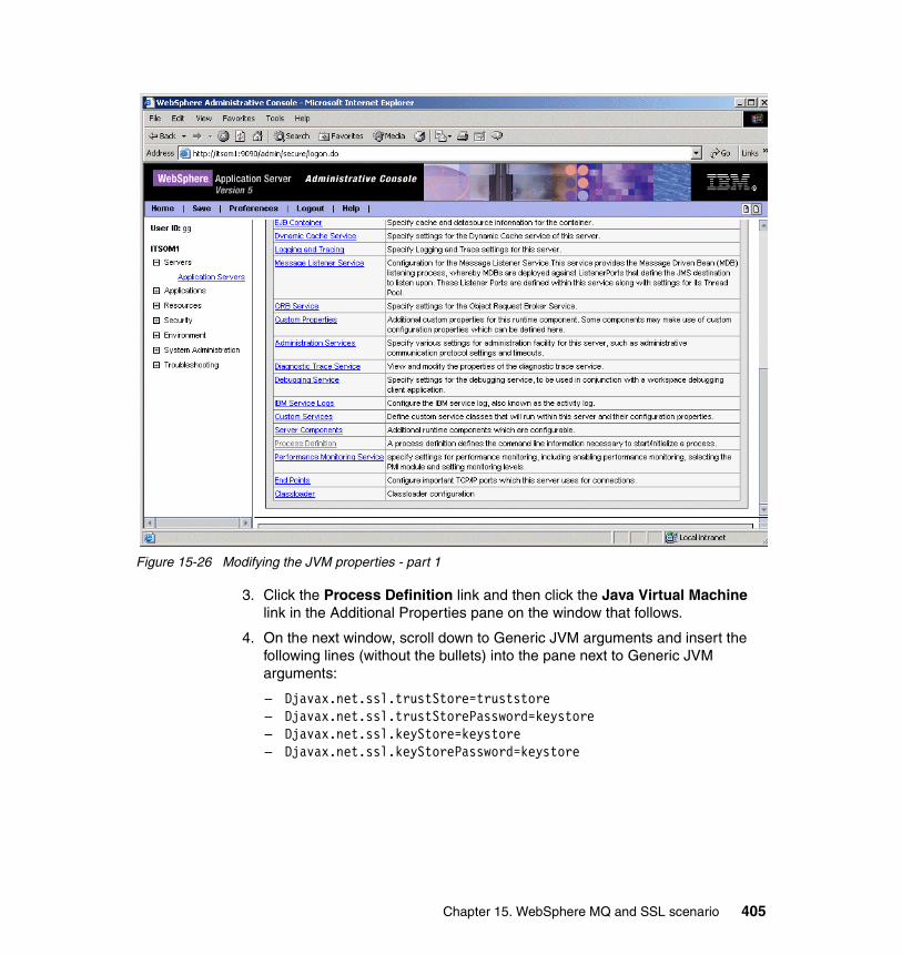
Figure 15-26 Modifying the JVM properties - part 1
3. Click the Process Definition link and then click the Java Virtual Machine link in the Additional Properties pane on the window that follows.
4. On the next window, scroll down to Generic JVM arguments and insert the following lines (without the bullets) into the pane next to Generic JVM arguments:
– Djavax.net.ssl.trustStore=truststore– Djavax.net.ssl.trustStorePassword=keystore– Djavax.net.ssl.keyStore=keystore– Djavax.net.ssl.keyStorePassword=keystore
Chapter 15. WebSphere MQ and SSL scenario 405
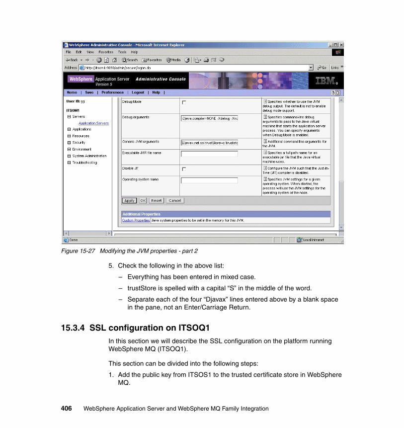
Figure 15-27 Modifying the JVM properties - part 2
5. Check the following in the above list:
– Everything has been entered in mixed case.
– trustStore is spelled with a capital “S” in the middle of the word.
– Separate each of the four “Djavax” lines entered above by a blank space in the pane, not an Enter/Carriage Return.
15.3.4 SSL configuration on ITSOQ1In this section we will describe the SSL configuration on the platform running WebSphere MQ (ITSOQ1).
This section can be divided into the following steps:
1. Add the public key from ITSOS1 to the trusted certificate store in WebSphere MQ.
406 WebSphere Application Server and WebSphere MQ Family Integration
2. Create the server connection channel in WebSphere MQ and define it as SSL.
Add certificate to WebSphere MQIn this step we add the certificate to the trusted store recognized by ITSOQ_QMGR. (This is the public key certificate we created in “Create public key” on page 404).
Create server connection channelWe used the following command to create the SVRCONN channel needed by ITSOQ_QMGR to accept a client connection request on an SSL secured channel from a Java client running on ITSOS1:
runmqsc ITSOQ_QMGR
When the system prompt appears, enter define channel(ITSO_SVRCONN) chltype(SVRCONN) SSLCIPH(TRIPLE_DES_SHA_US)
Note: If you use the WebSphere MQ Explorer to define this channel, make sure that you select Always authenticate parties initiating connections to this channel definition on the SSL tab of the SVRCONN channel definition.
Chapter 15. WebSphere MQ and SSL scenario 407
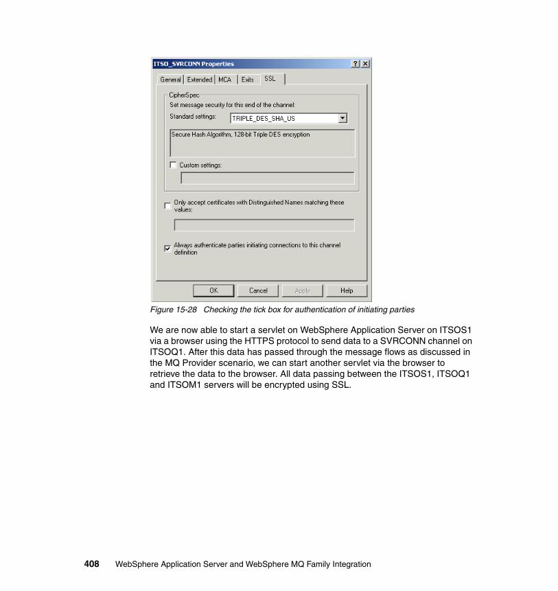
Figure 15-28 Checking the tick box for authentication of initiating parties
We are now able to start a servlet on WebSphere Application Server on ITSOS1 via a browser using the HTTPS protocol to send data to a SVRCONN channel on ITSOQ1. After this data has passed through the message flows as discussed in the MQ Provider scenario, we can start another servlet via the browser to retrieve the data to the browser. All data passing between the ITSOS1, ITSOQ1 and ITSOM1 servers will be encrypted using SSL.
408 WebSphere Application Server and WebSphere MQ Family Integration

Part 3 Appendixes
Part 3
© Copyright IBM Corp. 2003. All rights reserved. 409

410 WebSphere Application Server and WebSphere MQ Family Integration
Appendix A. WebSphere MQ SupportPacs
This appendix describes the following WebSphere MQ SupportPacs used in this IBM Redbook:
� MA88: MQSeries classes for Java and Java Message Service
� MA0C: MQSeries - Publish/Subscribe
A
© Copyright IBM Corp. 2003. All rights reserved. 411
A.1 MA88: MQSeries classes for Java and Java Message Service
This WebSphere MQ SupportPac contains the following components.
A.1.1 MQSeries classes for JavaThe MQSeries classes for Java allow a program written in the Java programming language to connect to MQSeries as an MQSeries client using TCP/IP, or directly to an MQSeries server using the Java Native Interface (JNI). They allow Java applets, applications, and servlets access to the messaging and queuing services of MQ. If the client-style connection is used, no additional MQ code is required on the client machine. The MQSeries classes for Java enable a message-based approach to application integration using Java.
A.1.2 MQSeries classes for Java Message Service (JMS)MQSeries classes for Java Message Service is a set of Java classes that implement Sun Microsystem's Java Message Service specification. A JMS application can use the classes to send MQ messages to either existing MQ or new JMS applications. An application can be configured to connect as an MQSeries client using TCP/IP, or directly using the Java Native Interface (JNI). If the client-style connection is used, no additional MQ code is required on the client machine.
Use of the MQSeries classes for Java Message Service offers benefits associated with using an open standard to write MQ applications, such as the protection of investment both in skills and application code. In addition the JMS classes provide some additional features not present in the MQSeries classes for Java. These extra features include:
� Explicit support for publish and subscribe � Asynchronous message delivery � Message selectors � Structured message classes � Support for XA transactions via the XAResource interface (not available for
OS/390® or z/OS).
WebSphere MQ SupportPac MA88 is available from:
http://www-3.ibm.com/software/integration/support/supportpacs/individual/ma88.html
412 WebSphere Application Server and WebSphere MQ Family Integration
A.2 MA0C: MQSeries - Publish/SubscribeA provider of information is called a publisher. Publishers supply information about one or more topics, such as stock prices, sport, or weather reports. This information is published by sending MQ messages to a Publish/Subscribe broker, which forwards it to other brokers in the network as needed.
A consumer of information is called a subscriber. Subscribers choose the topics for which they want to receive information. The brokers route any publications on those topics to them, again using MQ messages.
There can be more than one publisher for a particular topic, and subscribers can receive publications on as many topics as they choose. Each MQ queue manager can have one MQSeries Publish/Subscribe broker installed on it.
WebSphere MQ SupportPac MA0C is available from:
http://www-3.ibm.com/software/ts/mqseries/txppacs/ma0c.html
Appendix A. WebSphere MQ SupportPacs 413

414 WebSphere Application Server and WebSphere MQ Family Integration

Appendix B. WebSphere MQ Provider scenario
This appendix contains additional information for the WebSphere MQ Provider scenario.
B
© Copyright IBM Corp. 2003. All rights reserved. 415
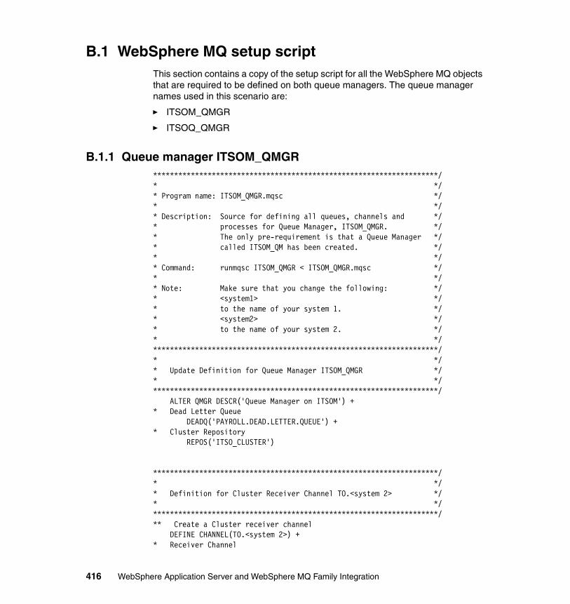
B.1 WebSphere MQ setup scriptThis section contains a copy of the setup script for all the WebSphere MQ objects that are required to be defined on both queue managers. The queue manager names used in this scenario are:
� ITSOM_QMGR
� ITSOQ_QMGR
B.1.1 Queue manager ITSOM_QMGR********************************************************************/* */* Program name: ITSOM_QMGR.mqsc */* */* Description: Source for defining all queues, channels and */* processes for Queue Manager, ITSOM_QMGR. */* The only pre-requirement is that a Queue Manager */* called ITSOM_QM has been created. */* */* Command: runmqsc ITSOM_QMGR < ITSOM_QMGR.mqsc */* */* Note: Make sure that you change the following: */* <system1> */* to the name of your system 1. */* <system2> */* to the name of your system 2. */* */********************************************************************/* */* Update Definition for Queue Manager ITSOM_QMGR */* */********************************************************************/ ALTER QMGR DESCR('Queue Manager on ITSOM') +* Dead Letter Queue DEADQ('PAYROLL.DEAD.LETTER.QUEUE') + * Cluster Repository REPOS('ITSO_CLUSTER')
********************************************************************/* */* Definition for Cluster Receiver Channel TO.<system 2> */* */********************************************************************/** Create a Cluster receiver channel DEFINE CHANNEL(TO.<system 2>) +* Receiver Channel
416 WebSphere Application Server and WebSphere MQ Family Integration
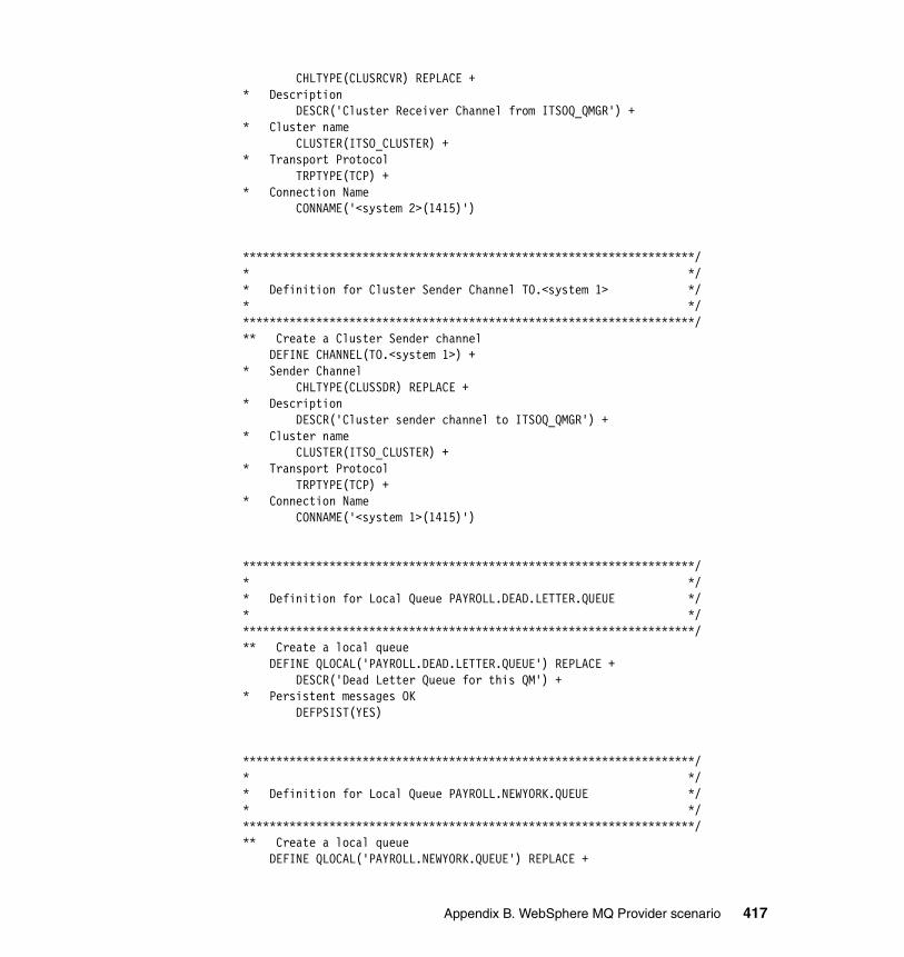
CHLTYPE(CLUSRCVR) REPLACE +* Description DESCR('Cluster Receiver Channel from ITSOQ_QMGR') +* Cluster name CLUSTER(ITSO_CLUSTER) +* Transport Protocol TRPTYPE(TCP) +* Connection Name CONNAME('<system 2>(1415)')
********************************************************************/* */* Definition for Cluster Sender Channel TO.<system 1> */* */********************************************************************/** Create a Cluster Sender channel DEFINE CHANNEL(TO.<system 1>) +* Sender Channel CHLTYPE(CLUSSDR) REPLACE +* Description DESCR('Cluster sender channel to ITSOQ_QMGR') +* Cluster name CLUSTER(ITSO_CLUSTER) +* Transport Protocol TRPTYPE(TCP) +* Connection Name CONNAME('<system 1>(1415)')
********************************************************************/* */* Definition for Local Queue PAYROLL.DEAD.LETTER.QUEUE */* */********************************************************************/** Create a local queue DEFINE QLOCAL('PAYROLL.DEAD.LETTER.QUEUE') REPLACE + DESCR('Dead Letter Queue for this QM') +* Persistent messages OK DEFPSIST(YES)
********************************************************************/* */* Definition for Local Queue PAYROLL.NEWYORK.QUEUE */* */********************************************************************/** Create a local queue DEFINE QLOCAL('PAYROLL.NEWYORK.QUEUE') REPLACE +
Appendix B. WebSphere MQ Provider scenario 417
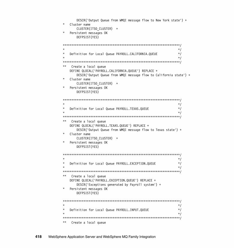
DESCR('Output Queue from WMQI message flow to New York state') +* Cluster name CLUSTER(ITSO_CLUSTER) +* Persistent messages OK DEFPSIST(YES)
********************************************************************/* */* Definition for Local Queue PAYROLL.CALIFORNIA.QUEUE */* */********************************************************************/** Create a local queue DEFINE QLOCAL('PAYROLL.CALIFORNIA.QUEUE') REPLACE + DESCR('Output Queue from WMQI message flow to California state') +* Cluster name CLUSTER(ITSO_CLUSTER) +* Persistent messages OK DEFPSIST(YES)
********************************************************************/* */* Definition for Local Queue PAYROLL.TEXAS.QUEUE */* */********************************************************************/** Create a local queue DEFINE QLOCAL('PAYROLL.TEXAS.QUEUE') REPLACE + DESCR('Output Queue from WMQI message flow to Texas state') +* Cluster name CLUSTER(ITSO_CLUSTER) +* Persistent messages OK DEFPSIST(YES)
********************************************************************/* */* Definition for Local Queue PAYROLL.EXCEPTION.QUEUE */* */********************************************************************/** Create a local queue DEFINE QLOCAL('PAYROLL.EXCEPTION.QUEUE') REPLACE + DESCR('Exceptions generated by Payroll system') +* Persistent messages OK DEFPSIST(YES)
********************************************************************/* */* Definition for Local Queue PAYROLL.INPUT.QUEUE */* */********************************************************************/** Create a local queue
418 WebSphere Application Server and WebSphere MQ Family Integration
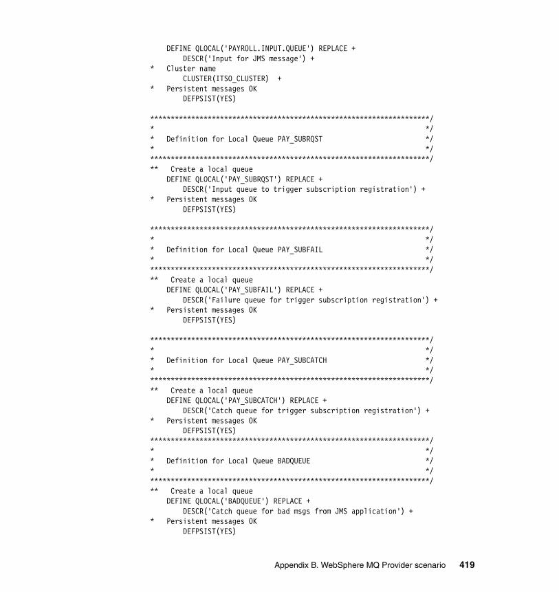
DEFINE QLOCAL('PAYROLL.INPUT.QUEUE') REPLACE + DESCR('Input for JMS message') +* Cluster name CLUSTER(ITSO_CLUSTER) +* Persistent messages OK DEFPSIST(YES)
********************************************************************/* */* Definition for Local Queue PAY_SUBRQST */* */********************************************************************/** Create a local queue DEFINE QLOCAL('PAY_SUBRQST') REPLACE + DESCR('Input queue to trigger subscription registration') +* Persistent messages OK DEFPSIST(YES)
********************************************************************/* */* Definition for Local Queue PAY_SUBFAIL */* */********************************************************************/** Create a local queue DEFINE QLOCAL('PAY_SUBFAIL') REPLACE + DESCR('Failure queue for trigger subscription registration') +* Persistent messages OK DEFPSIST(YES)
********************************************************************/* */* Definition for Local Queue PAY_SUBCATCH */* */********************************************************************/** Create a local queue DEFINE QLOCAL('PAY_SUBCATCH') REPLACE + DESCR('Catch queue for trigger subscription registration') +* Persistent messages OK DEFPSIST(YES)********************************************************************/* */* Definition for Local Queue BADQUEUE */* */********************************************************************/** Create a local queue DEFINE QLOCAL('BADQUEUE') REPLACE + DESCR('Catch queue for bad msgs from JMS application') +* Persistent messages OK DEFPSIST(YES)
Appendix B. WebSphere MQ Provider scenario 419
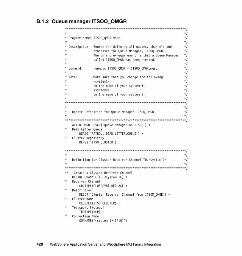
B.1.2 Queue manager ITSOQ_QMGR********************************************************************/* */* Program name: ITSOQ_QMGR.mqsc */* */* Description: Source for defining all queues, channels and */* processes for Queue Manager, ITSOQ_QMGR. */* The only pre-requirement is that a Queue Manager */* called ITSOQ_QMGR has been created. */* */* Command: runmqsc ITSOQ_QMGR < ITSOQ_QMGR.mqsc */* */* Note: Make sure that you change the following: */* <system1> */* to the name of your system 1. */* <system2> */* to the name of your system 2. */* */********************************************************************/* */* Update Definition for Queue Manager ITSOQ_QMGR */* */********************************************************************/ ALTER QMGR DESCR('Queue Manager on ITSOQ') +* Dead Letter Queue DEADQ('PAYROLL.DEAD.LETTER.QUEUE') +* Cluster Repository REPOS('ITSO_CLUSTER')
********************************************************************/* */* Definition for Cluster Receiver Channel TO.<system 1> */* */********************************************************************/** Create a Cluster Receiver Channel DEFINE CHANNEL(TO.<system 1>) +* Receiver Channel CHLTYPE(CLUSRCVR) REPLACE +* Description DESCR('Cluster Receiver Channel from ITSOM_QMGR') +* Cluster name CLUSTER(ITSO_CLUSTER) +* Transport Protocol TRPTYPE(TCP) + * Connection Name CONNAME('<system 1>(1415)')
420 WebSphere Application Server and WebSphere MQ Family Integration
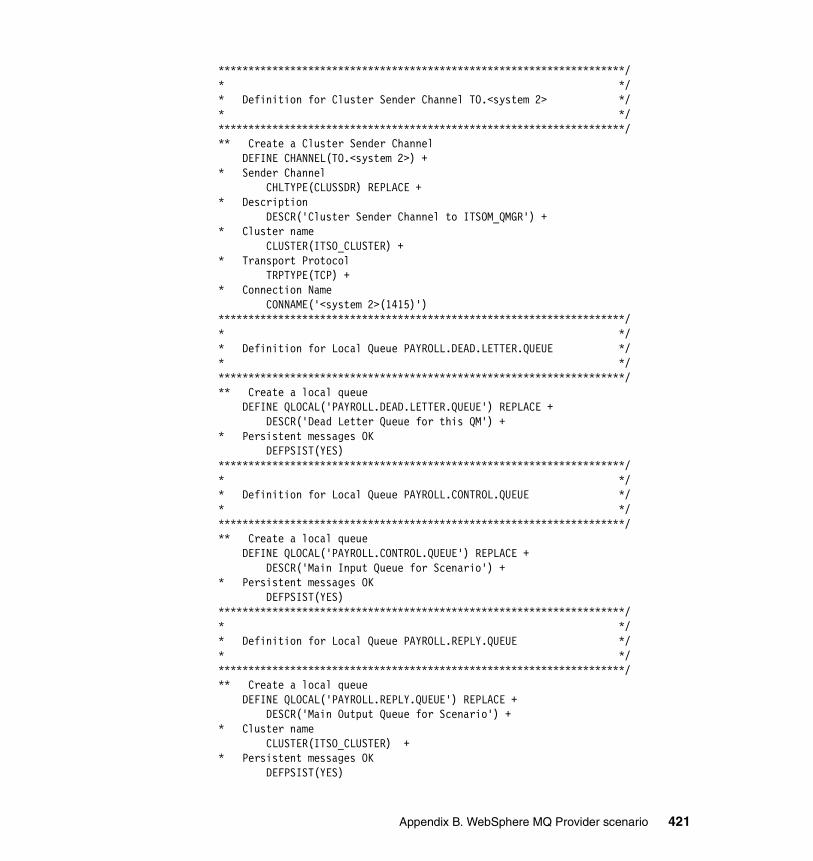
********************************************************************/* */* Definition for Cluster Sender Channel TO.<system 2> */* */********************************************************************/** Create a Cluster Sender Channel DEFINE CHANNEL(TO.<system 2>) +* Sender Channel CHLTYPE(CLUSSDR) REPLACE +* Description DESCR('Cluster Sender Channel to ITSOM_QMGR') +* Cluster name CLUSTER(ITSO_CLUSTER) +* Transport Protocol TRPTYPE(TCP) +* Connection Name CONNAME('<system 2>(1415)') ********************************************************************/* */* Definition for Local Queue PAYROLL.DEAD.LETTER.QUEUE */* */********************************************************************/** Create a local queue DEFINE QLOCAL('PAYROLL.DEAD.LETTER.QUEUE') REPLACE + DESCR('Dead Letter Queue for this QM') +* Persistent messages OK DEFPSIST(YES) ********************************************************************/* */* Definition for Local Queue PAYROLL.CONTROL.QUEUE */* */********************************************************************/** Create a local queue DEFINE QLOCAL('PAYROLL.CONTROL.QUEUE') REPLACE + DESCR('Main Input Queue for Scenario') +* Persistent messages OK DEFPSIST(YES) ********************************************************************/* */* Definition for Local Queue PAYROLL.REPLY.QUEUE */* */********************************************************************/** Create a local queue DEFINE QLOCAL('PAYROLL.REPLY.QUEUE') REPLACE + DESCR('Main Output Queue for Scenario') +* Cluster name CLUSTER(ITSO_CLUSTER) +* Persistent messages OK DEFPSIST(YES)
Appendix B. WebSphere MQ Provider scenario 421
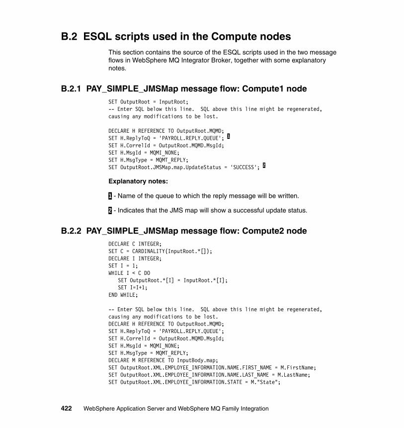
B.2 ESQL scripts used in the Compute nodesThis section contains the source of the ESQL scripts used in the two message flows in WebSphere MQ Integrator Broker, together with some explanatory notes.
B.2.1 PAY_SIMPLE_JMSMap message flow: Compute1 nodeSET OutputRoot = InputRoot;-- Enter SQL below this line. SQL above this line might be regenerated, causing any modifications to be lost.
DECLARE H REFERENCE TO OutputRoot.MQMD;SET H.ReplyToQ = 'PAYROLL.REPLY.QUEUE'; 1
SET H.CorrelId = OutputRoot.MQMD.MsgId;SET H.MsgId = MQMI_NONE;SET H.MsgType = MQMT_REPLY;SET OutputRoot.JMSMap.map.UpdateStatus = 'SUCCESS'; 2
Explanatory notes:
1 - Name of the queue to which the reply message will be written.
2 - Indicates that the JMS map will show a successful update status.
B.2.2 PAY_SIMPLE_JMSMap message flow: Compute2 nodeDECLARE C INTEGER;SET C = CARDINALITY(InputRoot.*[]);DECLARE I INTEGER;SET I = 1;WHILE I < C DO
SET OutputRoot.*[I] = InputRoot.*[I];SET I=I+1;
END WHILE;
-- Enter SQL below this line. SQL above this line might be regenerated, causing any modifications to be lost.DECLARE H REFERENCE TO OutputRoot.MQMD;SET H.ReplyToQ = 'PAYROLL.REPLY.QUEUE';SET H.CorrelId = OutputRoot.MQMD.MsgId;SET H.MsgId = MQMI_NONE;SET H.MsgType = MQMT_REPLY;DECLARE M REFERENCE TO InputBody.map;SET OutputRoot.XML.EMPLOYEE_INFORMATION.NAME.FIRST_NAME = M.FirstName;SET OutputRoot.XML.EMPLOYEE_INFORMATION.NAME.LAST_NAME = M.LastName;SET OutputRoot.XML.EMPLOYEE_INFORMATION.STATE = M."State";
422 WebSphere Application Server and WebSphere MQ Family Integration
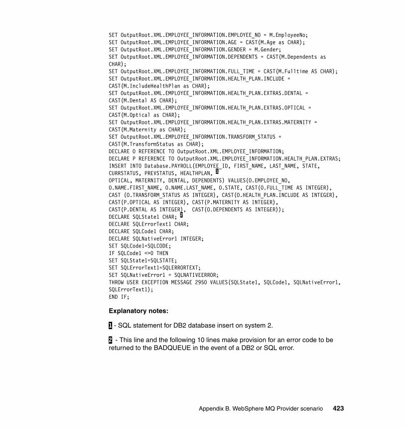
SET OutputRoot.XML.EMPLOYEE_INFORMATION.EMPLOYEE_NO = M.EmployeeNo;SET OutputRoot.XML.EMPLOYEE_INFORMATION.AGE = CAST(M.Age as CHAR);SET OutputRoot.XML.EMPLOYEE_INFORMATION.GENDER = M.Gender;SET OutputRoot.XML.EMPLOYEE_INFORMATION.DEPENDENTS = CAST(M.Dependents as CHAR);SET OutputRoot.XML.EMPLOYEE_INFORMATION.FULL_TIME = CAST(M.Fulltime AS CHAR);SET OutputRoot.XML.EMPLOYEE_INFORMATION.HEALTH_PLAN.INCLUDE = CAST(M.IncludeHealthPlan as CHAR);SET OutputRoot.XML.EMPLOYEE_INFORMATION.HEALTH_PLAN.EXTRAS.DENTAL = CAST(M.Dental AS CHAR);SET OutputRoot.XML.EMPLOYEE_INFORMATION.HEALTH_PLAN.EXTRAS.OPTICAL = CAST(M.Optical as CHAR);SET OutputRoot.XML.EMPLOYEE_INFORMATION.HEALTH_PLAN.EXTRAS.MATERNITY = CAST(M.Maternity as CHAR);SET OutputRoot.XML.EMPLOYEE_INFORMATION.TRANSFORM_STATUS = CAST(M.TransformStatus as CHAR);DECLARE O REFERENCE TO OutputRoot.XML.EMPLOYEE_INFORMATION;DECLARE P REFERENCE TO OutputRoot.XML.EMPLOYEE_INFORMATION.HEALTH_PLAN.EXTRAS;INSERT INTO Database.PAYROLL(EMPLOYEE_ID, FIRST_NAME, LAST_NAME, STATE, CURRSTATUS, PREVSTATUS, HEALTHPLAN, 1
OPTICAL, MATERNITY, DENTAL, DEPENDENTS) VALUES(O.EMPLOYEE_NO, O.NAME.FIRST_NAME, O.NAME.LAST_NAME, O.STATE, CAST(O.FULL_TIME AS INTEGER), CAST (O.TRANSFORM_STATUS AS INTEGER), CAST(O.HEALTH_PLAN.INCLUDE AS INTEGER), CAST(P.OPTICAL AS INTEGER), CAST(P.MATERNITY AS INTEGER), CAST(P.DENTAL AS INTEGER), CAST(O.DEPENDENTS AS INTEGER));DECLARE SQLState1 CHAR; 2
DECLARE SQLErrorText1 CHAR;DECLARE SQLCode1 CHAR;DECLARE SQLNativeError1 INTEGER;SET SQLCode1=SQLCODE;IF SQLCode1 <>0 THENSET SQLState1=SQLSTATE;SET SQLErrorText1=SQLERRORTEXT;SET SQLNativeError1 = SQLNATIVEERROR;THROW USER EXCEPTION MESSAGE 2950 VALUES(SQLState1, SQLCode1, SQLNativeError1, SQLErrorText1);END IF;
Explanatory notes:
1 - SQL statement for DB2 database insert on system 2.
2 - This line and the following 10 lines make provision for an error code to be returned to the BADQUEUE in the event of a DB2 or SQL error.
Appendix B. WebSphere MQ Provider scenario 423
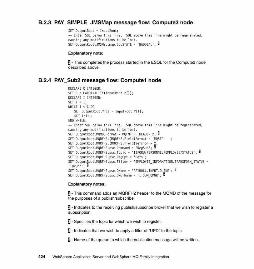
B.2.3 PAY_SIMPLE_JMSMap message flow: Compute3 nodeSET OutputRoot = InputRoot;-- Enter SQL below this line. SQL above this line might be regenerated, causing any modifications to be lost.SET OutputRoot.JMSMap.map.SQLSTATE = 'BADDEAL'; 1
Explanatory note:
1 - This completes the process started in the ESQL for the Compute2 node described above.
B.2.4 PAY_Sub2 message flow: Compute1 nodeDECLARE C INTEGER;SET C = CARDINALITY(InputRoot.*[]);DECLARE I INTEGER;SET I = 1;WHILE I < C DO
SET OutputRoot.*[I] = InputRoot.*[I];SET I=I+1;
END WHILE;-- Enter SQL below this line. SQL above this line might be regenerated, causing any modifications to be lost.SET OutputRoot.MQMD.Format = MQFMT_RF_HEADER_2; 1
SET OutputRoot.MQRFH2.(MQRFH2.Field)Format = 'MQSTR ';SET OutputRoot.MQRFH2.(MQRFH2.Field)Version = 2;SET OutputRoot.MQRFH2.psc.Command = 'RegSub'; 2
SET OutputRoot.MQRFH2.psc.Topic = 'TZFORU/PERSONNEL/EMPLOYEE/STATUS'; 3
SET OutputRoot.MQRFH2.psc.RegOpt = 'Pers';SET OutputRoot.MQRFH2.psc.Filter = 'EMPLOYEE_INFORMATION.TRANSFORM_STATUS = ''UPD'''; 4
SET OutputRoot.MQRFH2.psc.QName = 'PAYROLL.INPUT.QUEUE'; 5
SET OutputRoot.MQRFH2.psc.QMgrName = 'ITSOM_QMGR'; 6
Explanatory notes:
1 - This command adds an MQRFH2 header to the MQMD of the message for the purposes of a publish/subscribe.
2 - Indicates to the receiving publish/subscribe broker that we wish to register a subscription.
3 - Specifies the topic for which we wish to register.
4 - Indicates that we wish to apply a filter of “UPD” to the topic.
5 - Name of the queue to which the publication message will be written.
424 WebSphere Application Server and WebSphere MQ Family Integration
6 - Name of the queue manager owning the queue in 5 above.
B.3 Disabling Embedded MessagingWhen using WebSphere MQ V5.3.0.1 with WebSphere Application Server V5, from time to time we may need to disable the Embedded Messaging components within the server. We may also need to do this when using earlier versions of WebSphere MQ or other generic providers.
To disable WebSphere Application Server’s internal JMS Server, follow the process below:
1. Open the WebSphere Application Server Administrative Console and expand the Servers heading. Then select the link called Application Servers.
2. A list of the currently configured servers will be displayed. If WebSphere Application Server has recently been installed and only the MQ Provider scenario has been completed so far, there should only be one server available to select (this will probably be caller server1). Select the server and this will display the servers configuration.
3. Select the link called Server Components on the configuration tab.
4. Select the link called JMS Servers. The JMS Servers configuration will now be displayed.
5. In the general properties of the JMS Server, the initial state of the server will have defaulted to Started. Change the initial state to Stopped. These are no other properties on this configuration page that need to be modified.
The JMS Servers configuration page should look like Figure B-1 on page 426.
Appendix B. WebSphere MQ Provider scenario 425
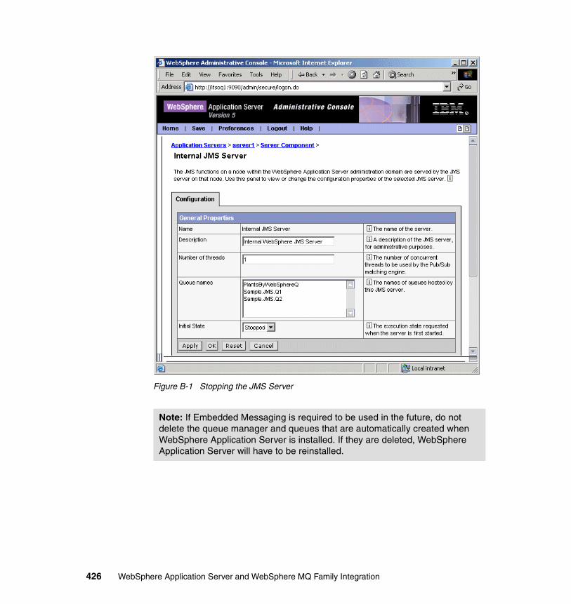
Figure B-1 Stopping the JMS Server
Note: If Embedded Messaging is required to be used in the future, do not delete the queue manager and queues that are automatically created when WebSphere Application Server is installed. If they are deleted, WebSphere Application Server will have to be reinstalled.
426 WebSphere Application Server and WebSphere MQ Family Integration
Appendix C. WebSphere MQ and SSL scenario
This appendix contains additional information for the WebSphere MQ and SSL scenario.
C
© Copyright IBM Corp. 2003. All rights reserved. 427
WebSphere Application Server traceIncluded below are the instructions for turning trace on within WebSphere Application Server. We found this trace extremely useful when establishing errors with an SSL configuration, as the standard system out file produced did not supply enough detail to isolate the problem. There are two separate trace settings that are required to be configured. They are:
� Generic JVM arguments in the JVM� Trace specification in the Diagnostic Trace Service
Generic JVM argumentsTo configure the generic JVM arguments, do the following:
1. Open the WebSphere Application Server Administrative Console and expand the Servers folder and click Application Servers. Select the predefined server, which will probably be called “server1”.
2. Once the Configuration Properties for the server are displayed, go to the Additional Properties at the bottom of the window and select Process Definition. Once the Process Definition properties are displayed, go to the Additional Properties and select Java Virtual Machine.
3. Once the configuration properties for the Java Virtual Machine are displayed, an additional argument is required to be entered in the Generic JVM Arguments field:
-DMQJMS_TRACE_LEVEL=baseI
4. Click the Save link at the top of the Web page to save the configuration.
The Generic JVM Arguments field on the JVM properties Web page is shown in Figure C-1 on page 429.
Note: If there are already arguments in this field, a space should be used as the separator. Also note that case is important when entering this argument.
428 WebSphere Application Server and WebSphere MQ Family Integration
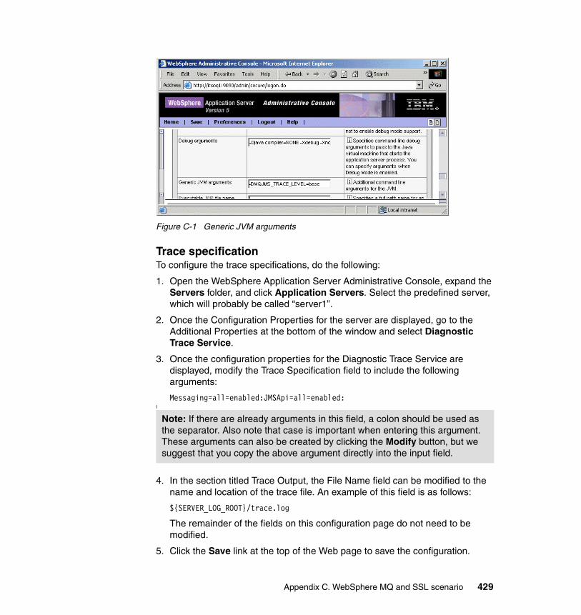
Figure C-1 Generic JVM arguments
Trace specificationTo configure the trace specifications, do the following:
1. Open the WebSphere Application Server Administrative Console, expand the Servers folder, and click Application Servers. Select the predefined server, which will probably be called “server1”.
2. Once the Configuration Properties for the server are displayed, go to the Additional Properties at the bottom of the window and select Diagnostic Trace Service.
3. Once the configuration properties for the Diagnostic Trace Service are displayed, modify the Trace Specification field to include the following arguments:
Messaging=all=enabled:JMSApi=all=enabled:I
4. In the section titled Trace Output, the File Name field can be modified to the name and location of the trace file. An example of this field is as follows:
${SERVER_LOG_ROOT}/trace.log
The remainder of the fields on this configuration page do not need to be modified.
5. Click the Save link at the top of the Web page to save the configuration.
Note: If there are already arguments in this field, a colon should be used as the separator. Also note that case is important when entering this argument. These arguments can also be created by clicking the Modify button, but we suggest that you copy the above argument directly into the input field.
Appendix C. WebSphere MQ and SSL scenario 429
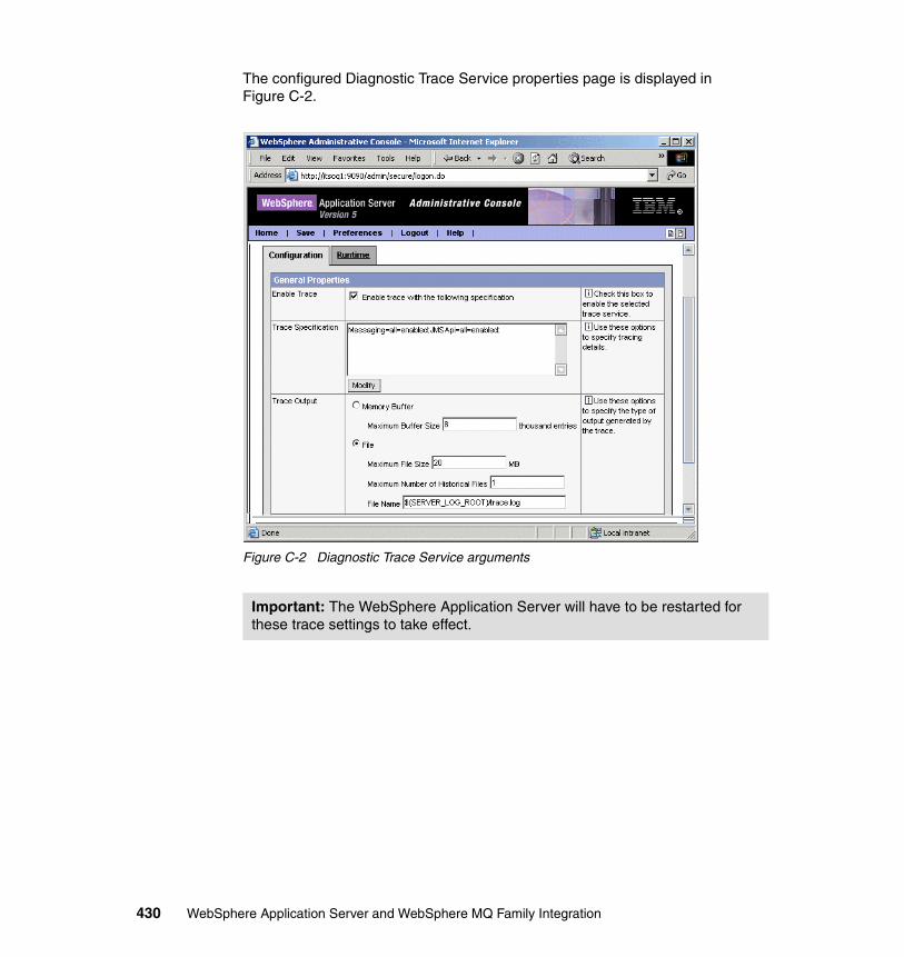
The configured Diagnostic Trace Service properties page is displayed in Figure C-2.
Figure C-2 Diagnostic Trace Service arguments
Important: The WebSphere Application Server will have to be restarted for these trace settings to take effect.
430 WebSphere Application Server and WebSphere MQ Family Integration
Appendix D. Generic provider scenario
This appendix contains additional information for the WebSphere Application Server Generic JMS Provider scenario.
D
© Copyright IBM Corp. 2003. All rights reserved. 431
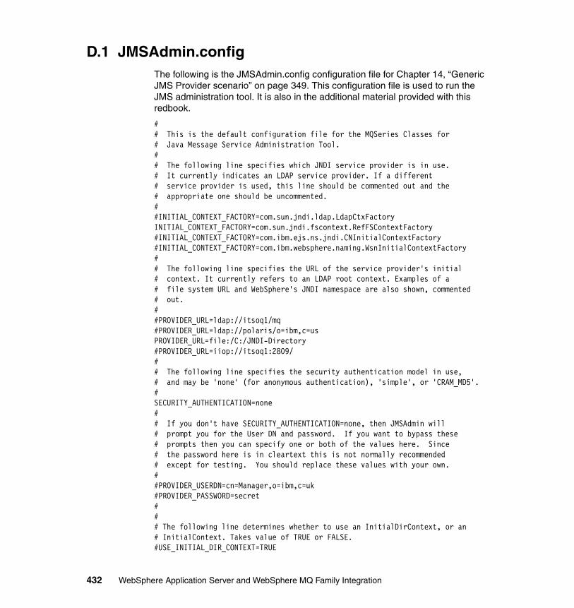
D.1 JMSAdmin.configThe following is the JMSAdmin.config configuration file for Chapter 14, “Generic JMS Provider scenario” on page 349. This configuration file is used to run the JMS administration tool. It is also in the additional material provided with this redbook.
## This is the default configuration file for the MQSeries Classes for# Java Message Service Administration Tool.## The following line specifies which JNDI service provider is in use.# It currently indicates an LDAP service provider. If a different# service provider is used, this line should be commented out and the# appropriate one should be uncommented.##INITIAL_CONTEXT_FACTORY=com.sun.jndi.ldap.LdapCtxFactoryINITIAL_CONTEXT_FACTORY=com.sun.jndi.fscontext.RefFSContextFactory#INITIAL_CONTEXT_FACTORY=com.ibm.ejs.ns.jndi.CNInitialContextFactory#INITIAL_CONTEXT_FACTORY=com.ibm.websphere.naming.WsnInitialContextFactory## The following line specifies the URL of the service provider's initial# context. It currently refers to an LDAP root context. Examples of a# file system URL and WebSphere's JNDI namespace are also shown, commented# out.##PROVIDER_URL=ldap://itsoq1/mq#PROVIDER_URL=ldap://polaris/o=ibm,c=usPROVIDER_URL=file:/C:/JNDI-Directory#PROVIDER_URL=iiop://itsoq1:2809/## The following line specifies the security authentication model in use,# and may be 'none' (for anonymous authentication), 'simple', or 'CRAM_MD5'.#SECURITY_AUTHENTICATION=none## If you don't have SECURITY_AUTHENTICATION=none, then JMSAdmin will# prompt you for the User DN and password. If you want to bypass these# prompts then you can specify one or both of the values here. Since# the password here is in cleartext this is not normally recommended# except for testing. You should replace these values with your own.##PROVIDER_USERDN=cn=Manager,o=ibm,c=uk#PROVIDER_PASSWORD=secret### The following line determines whether to use an InitialDirContext, or an# InitialContext. Takes value of TRUE or FALSE.#USE_INITIAL_DIR_CONTEXT=TRUE
432 WebSphere Application Server and WebSphere MQ Family Integration
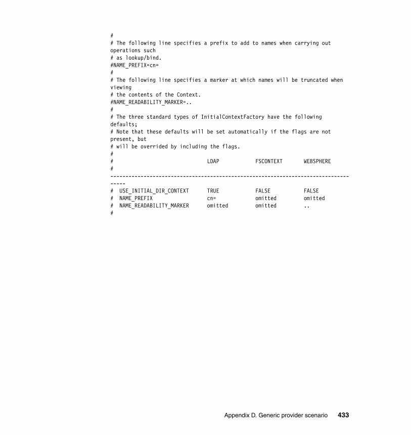
## The following line specifies a prefix to add to names when carrying out operations such# as lookup/bind.#NAME_PREFIX=cn=## The following line specifies a marker at which names will be truncated when viewing# the contents of the Context.#NAME_READABILITY_MARKER=..## The three standard types of InitialContextFactory have the following defaults;# Note that these defaults will be set automatically if the flags are not present, but# will be overrided by including the flags.## LDAP FSCONTEXT WEBSPHERE# ------------------------------------------------------------------------------------# USE_INITIAL_DIR_CONTEXT TRUE FALSE FALSE# NAME_PREFIX cn= omitted omitted# NAME_READABILITY_MARKER omitted omitted ..#
Appendix D. Generic provider scenario 433

434 WebSphere Application Server and WebSphere MQ Family Integration
Appendix E. Additional material
This redbook refers to additional material that can be downloaded from the Internet as described below.
Locating the Web materialThe Web material associated with this redbook is available in softcopy on the Internet from the IBM Redbooks Web server. Point your Web browser to:
ftp://www.redbooks.ibm.com/redbooks/SG246878
Alternatively, you can go to the IBM Redbooks Web site at:
ibm.com/redbooks
Select the Additional materials and open the directory that corresponds with the redbook form number, SG246878.
Using the Web materialThe additional Web material that accompanies this redbook includes the following files:
File name DescriptionSG246878.zip Zipped code samples
E
© Copyright IBM Corp. 2003. All rights reserved. 435
System requirements for downloading the Web materialThe following system configuration is recommended:
Hard disk space: 5 MBOperating System: Windows 2000 Server or ProfessionalProcessor: 1 GHz or higherMemory: 512 MB or higher
How to use the Web materialCreate a subdirectory (folder) on your workstation, for example: C:\SG246878, and unzip the contents of the Web material zip file into this folder.
After unpacking the sample material you will find several directories and files under each directory, these are all part of the sample application used in this book. You can find further details about installing and configuring the sample application in Part 2, “Example scenarios” on page 65.
436 WebSphere Application Server and WebSphere MQ Family Integration
Related publications
The publications listed in this section are considered particularly suitable for a more detailed discussion of the topics covered in this redbook.
IBM RedbooksFor information on ordering these publications, see “How to get IBM Redbooks” on page 439.
� IBM WebSphere V5.0 Security, WebSphere Handbook Series, SG24-6573
� WebSphere MQ Security, SC34-6079
� WebSphere MQ Security in an Enterprise Environment, SG24-6814
� IBM WebSphere Application Server Version 5.0 Handbook, SG24-6195
Other resourcesThese publications are also relevant as further information sources:
� Selecting the most appropriate JMS provider for your applications, G325-2318-00, by Jamie Roots, June 2003; see:
http://www-1.ibm.com/support/docview.wss?uid=pub1e0f13e5870bf07b785256d8a0024ad63
� WebSphere MQ Queue Managers Clusters, SC34-6061
� WebSphere MQ Intercommunications, SC34-6059-01
� WebSphere MQ Event Broker Administration Guide, SC34-6093-01
� WebSphere MQ Integrator Broker Administration Guide, SC34-6171
� Implementing vendor-independent JMS solutions, written by Nicholas Whithead in February 2002 and available from IBM developerWorks at:
http://www-106.ibm.com/developerworks/library/j-jmsvendor/
� MQSeries V5.2 Using Java, SC34-5456-08
Referenced Web sitesThese Web sites are also relevant as further information sources:
© Copyright IBM Corp. 2003. All rights reserved. 437
� Eclipse organization
http://www.eclipse.org
� WebSphere Studio family overview
http://www-3.ibm.com/software/ad/adstudio/
� Web site of Cygwin, a Linux-like environment for Windows
http://www.cygwin.com
� SupportPac MA0C: MQSeries - Publish/Subscribe
http://www-3.ibm.com/software/ts/mqseries/txppacs/ma0c.html
� SupportPac MA88: MQSeries classes for Java and MQSeries classes for Java Message Service
http://www-3.ibm.com/software/integration/support/supportpacs/individual/ma88.html
� WebSphere MQ Integrator Broker
http://www-3.ibm.com/software/integration/mqfamily/integrator/broker/
� WebSphere MQ products
http://www-3.ibm.com/software/integration/wmq/
� WebSphere MQ Integrator, Version 2 Release 1
http://www-3.ibm.com/software/ts/mqseries/integrator/v21/index.html
� WebSphere MQ Event Broker
http://www-3.ibm.com/software/integration/mqfamily/eventbroker/
� WebSphere Application Server InfoCenter
http://www-3.ibm.com/software/webservers/appserv/infocenter.htmlhttp://publib.boulder.ibm.com/infocenter/wasinfo/index.jsp
� WebSphere MQ family downloads
http://www-3.ibm.com/software/integration/mqfamily/downloads/
438 WebSphere Application Server and WebSphere MQ Family Integration438 WebSphere Application Server and WebSphere MQ Family Integration
How to get IBM RedbooksYou can order hardcopy Redbooks, as well as view, download, or search for Redbooks at the following Web site:
ibm.com/redbooks
You can also download additional materials (code samples or diskette/CD-ROM images) from that site.
IBM Redbooks collectionsRedbooks are also available on CD-ROMs. Click the CD-ROMs button on the Redbooks Web site for information about all the CD-ROMs offered, as well as updates and formats.
Related publications 439

440 WebSphere Application Server and WebSphere MQ Family Integration440 WebSphere Application Server and WebSphere MQ Family Integration

Index
AAccess Control Lists 37ACID 262acknowledgment mode 268ActiveX application client 26Activity Sessions 28addNode command 225, 242, 254addnode process 245administration client 192Administrative.ear 199alias, Authentication 95, 165, 194ALTER CHANNEL command 390amqsput command 347anonymous publishers 15anonymous subscribers 15application client
ActiveX 26applet 26J2EE 26pluggable 26thin 26
Application Client Resource Configuration Tool 122Application Messaging Interface (AMI) 43application profiling 26application server
create 240mapping to modules 111toolkit 26
asymmetric encryption 371Asynchronous Beans 28asynchronous messaging 32, 48, 56
BIND transport type 10in classes for Java 412in message-driven beans 265
Atomicity 262authentication 371
certificate based 201client 404two way 399
Authentication alias 95, 165, 194
BbackupConfig command 232
© Copyright IBM Corp. 2003. All rights reserved.
batch mode 400bean-managed messaging 56bean-managed transactions 266, 272
in onMessage method 284logs 278
BestSellersCommandImpl 158, 184BestSellersServlet 158, 184binaries 62, 200, 255
updating 258bind mode 30BIND transport type 10bindings 101
connection factory 102bindings mode 327broker 27, 30
create a new broker 314currently available 16multiple in graph structure 20publish/subscribe 15
business logic 56
Ccache a subscriber 58cell 198, 259
add a node 225discovery 199incorporating a node 223new structure 227remove node 228–229scope 53, 193, 242
centralized administration vs. centralized manage-ment 52centralized topology 37cert.crt file 388cert.p12 file 388Certificate Authority 371certificates 371
add to WebSphere MQ 383adding to Windows 2000 379
channels 10, 19, 30–31, 370definitions 389
CipherSpec 372, 401TRIPLE_DES_SHU_US 401–402
441
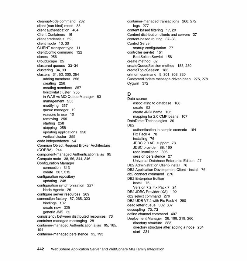
cleanupNode command 232client (non-bind) mode 33client authentication 404Client Containers 16client credentials 59client mode 10, 30CLIENT transport type 11clientConfig command 122clones 256CloudScape 25clustered queues 33–34clustering 34, 39clusters 31, 53, 200, 254
adding members 256creating 256creating members 257horizontal cluster 255in WAS vs MQ Queue Manager 53management 255modifying 257queue manager 19reasons to use 10removing 259starting 258stopping 258updating applications 258vertical cluster 255
code independence 54Common Object Request Broker Architecture (CORBA) 244component-managed Authentication alias 95Compute node 38, 56, 344, 346Configuration Manager
connection 313create 307, 312
configuration repositoryupdating 248
configuration synchronization 227Node Agents 26
configure server resources 209connection factory 57, 265, 323
bindings 102create new 325generic JMS 32
consistency between distributed resources 73container managed messaging 28container-managed Authentication alias 95, 165, 194container-managed persistence 95, 193
container-managed transactions 266, 272logs 277
content based filtering 17, 20Content distribution clients and servers 27content-based routing 37–38Control Server
startup configuration 77controller servlet 151
BestSellersServlet 158create method 62createQueueSession method 183, 280createTopicSession 183crtmqm command 9, 301, 303, 320CustomerUpdate message-driven bean 275, 278Cygwin 372
DData source
associating to database 166create 92create JNDI name 106mapping for 2.0 CMP beans 107
DataDirect Technologies 26DB2
authentication in sample scenario 164Fix Pack 4 78installing 76JDBC 2.0 API support 78JDBC provider 88, 160redo installation 306session persistence 27Universal Database Enterprise Edition 27
DB2 Administration Client- install 76DB2 Application Development Client - install 76db2 connect command 276DB2 Enterprise Edition
install 76Version 7.2 Fix Pack 7 24
DB2 JDBC Provider (XA) 192db2 select command 276DB2 UDB V7.2 with Fix Pack 4 290dead letter queue 302, 307decoupling 70, 73define channel command 407Deployment Manager 26, 198, 219, 260
directory structure 223directory structure after adding a node 234start 231
442 WebSphere Application Server and WebSphere MQ Family Integration
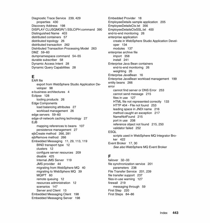
Diagnostic Trace Service 239, 429properties 430
Discovery Address 198DISPLAY CLUSQMGR(*) SSLCIPH command 390Distinguished Name 403distributed containers 57distributed topology 26distributed transaction 262Distributed Transaction Processing Model 263DMZ 59–60dumpnamespace command 54–55durable subscriber 58Dynamic Access Intent 28Dynamic Query Capabilities 28
EEAR file
export from WebSphere Studio Application De-veloper 98
e-business architectures 4Eclipse 128
tooling products 26Edge Components
load balancing attributes 27workload management 26
edge servers 59–60edge-of-network caching technology 27EJB
mapping references to beans 107persistence management 27
ejbCreate method 266, 281ejbRemove method 266Embedded Messaging 11, 29, 113, 119
BIND transport type 12clusters 12configure server resources 209disable 425Internal JMS Server 119JMS provider 44migrating from WebSphere MQ 40migrating to WebSphere MQ 39MQIPT 60remote queuing 12resources administration 12scenarios 147Server and Client 13
Embedded Messaging Client 198Embedded Messaging Server 198
Embedded Provider 18EmployeeDetails sample application 205EmployeeDetailsCtx.txt 356EmployeeDetailsCtxSSL.txt 400end-to-end monitoring 26enterprise application
create in WebSphere Studio Application Devel-oper 134modules 137
enterprise archive fileimport 358install 241
Enterprise Java Bean containersend-to-end monitoring 26weighting 26
Enterprise JavaBean 16Enterprise JavaBean workload management 199entity beans 266error
cannot find server or DNS Error 253cannot send message 215files in use 127HTML file not represented correctly 133HTTP 404 - File not found 253leading space in JNDI name 216method caught an exception 217NameNotFound 215port in use 208reference object not found 215, 250validator failed 252
ESQLscripts used in WebSphere MQ Integrator Bro-ker 422
Event Broker 17, 30See also WebSphere MQ Event Broker
Ffailover 32–33file synchronization service 201
parameters 238File Transfer Service 201, 239file transfer support 237files-in-use warning 127firewall 219
messaging through 59First Step 220First Steps 84–86
Index 443
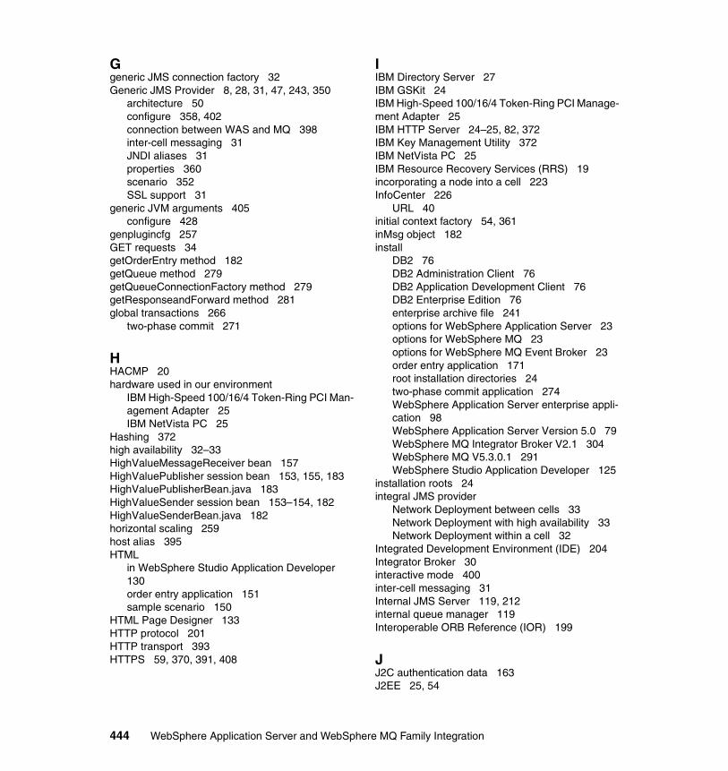
Ggeneric JMS connection factory 32Generic JMS Provider 8, 28, 31, 47, 243, 350
architecture 50configure 358, 402connection between WAS and MQ 398inter-cell messaging 31JNDI aliases 31properties 360scenario 352SSL support 31
generic JVM arguments 405configure 428
genplugincfg 257GET requests 34getOrderEntry method 182getQueue method 279getQueueConnectionFactory method 279getResponseandForward method 281global transactions 266
two-phase commit 271
HHACMP 20hardware used in our environment
IBM High-Speed 100/16/4 Token-Ring PCI Man-agement Adapter 25IBM NetVista PC 25
Hashing 372high availability 32–33HighValueMessageReceiver bean 157HighValuePublisher session bean 153, 155, 183HighValuePublisherBean.java 183HighValueSender session bean 153–154, 182HighValueSenderBean.java 182horizontal scaling 259host alias 395HTML
in WebSphere Studio Application Developer 130order entry application 151sample scenario 150
HTML Page Designer 133HTTP protocol 201HTTP transport 393HTTPS 59, 370, 391, 408
IIBM Directory Server 27IBM GSKit 24IBM High-Speed 100/16/4 Token-Ring PCI Manage-ment Adapter 25IBM HTTP Server 24–25, 82, 372IBM Key Management Utility 372IBM NetVista PC 25IBM Resource Recovery Services (RRS) 19incorporating a node into a cell 223InfoCenter 226
URL 40initial context factory 54, 361inMsg object 182install
DB2 76DB2 Administration Client 76DB2 Application Development Client 76DB2 Enterprise Edition 76enterprise archive file 241options for WebSphere Application Server 23options for WebSphere MQ 23options for WebSphere MQ Event Broker 23order entry application 171root installation directories 24two-phase commit application 274WebSphere Application Server enterprise appli-cation 98WebSphere Application Server Version 5.0 79WebSphere MQ Integrator Broker V2.1 304WebSphere MQ V5.3.0.1 291WebSphere Studio Application Developer 125
installation roots 24integral JMS provider
Network Deployment between cells 33Network Deployment with high availability 33Network Deployment within a cell 32
Integrated Development Environment (IDE) 204Integrator Broker 30interactive mode 400inter-cell messaging 31Internal JMS Server 119, 212internal queue manager 119Interoperable ORB Reference (IOR) 199
JJ2C authentication data 163J2EE 25, 54
444 WebSphere Application Server and WebSphere MQ Family Integration

application client 26compliant JMS providers 14create enterprise application project 135JMS provider 13messaging with non-J2EE applications 39navigator 130perspective in WebSphere Studio 129
J2EE Application Client Tool 122J2EE environment
lightweight 26J2EE namespace 54J2EE Navigator 190JAAS Authentication 192Java Management Extensions 27, 231–232Java Message Service 48, 50, 57, 59–60, 188, 412Java Message Service administration tool 432Java Message Service API 54Java Message Service for MQSeries 9Java Messaging 39Java Naming and Directory Interface See also JNDI 244Java Native Interface (JNI) 412Java Virtual Machine 32, 46, 403, 428
processes 26javax.jms.IllegalStateException 58javax.jms.Queue mapping 108javax.jms.QueueConnectionFactory mapping 108javax.jms.Topic mapping 109JDBC 2.0 78JDBC connection 193JDBC data source 192JDBC drivers 200
ConnectJDBC 26DataDirect Technologies 26path 162SequeLink 26
JDBC provider 88, 162available providers 160XA-compliant 160
JDBC resources, creating 88JDBC2 88JMS
administration tools 14creating entities 168messaging options 28send and receive 262
JMS administration 243JMS Connection Factory 9, 12JMS listener
security 59JMS MQ Provider 371JMS namespace 398, 402
definition 400JMS providers 8, 40, 116
features 30Generic 28integral 28–29J2EE-compliant 14multi-broker capability 31WebSphere MQ 28
JMS queue resource definition 211JMS Server 13, 29, 32, 46, 198, 202, 241
direct port in use 208failover 32internal 30, 119managed resources 49queued port in use 208queues 170
JMS Sessionstransactional 264
JMS/XA support 56JMS/XA transaction 57JMSAdmin 55, 353, 356, 400
administration verbs 357SSL output 401
JMSAdmin.config 353–354, 400, 432JMSIPInput node 38, 43JMSIPOptimizedFlow node 38, 43JMSMap 343–344JNDI bindings 251JNDI lookup 183, 361JNDI names 51, 211, 218, 248, 323, 362–363
for enterprise beans 106leading space error 216
JNDI namespace 9, 12, 54, 62, 179, 184, 219, 353JNDI service provider 432jndiLookup method 279JTA transaction control 56JVM See Java Virtual Machine
Kkey file 391, 394, 397key pair 403key store 403keytool command 403
Index 445
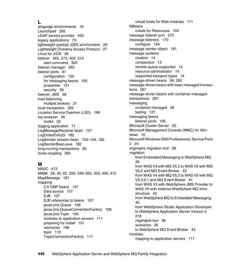
Llanguage environments 19Launchpad 292LDAP service provider 432legacy applications 73lightweight (partial) J2EE environment 26Lightweight Directory Access Protocol 27Linux for z/OS 38listener 265, 273, 303, 313
start command 320listener manager 265listener ports 61
configuration 120for messaging beans 105properties 121security 59
listener, JMS 56load balancing
multiple brokers 21local transaction 262Location Service Daemon (LSD) 199log analyzer 26
toolkit 26logging application 71LogMessageReceiver bean 157LogOrderEntryQ 182LogSender session bean 153–154, 182LogSenderBean.java 182long-running transactions 56loose coupling 264
MMA0C 413MA88 28, 35, 62, 293, 349–350, 353, 400, 412MapMessage 181mapping
2.0 CMP beans 107Data source 107EJB 107EJB references to beans 107javax.jms.Queue 108javax.jms.QueueConnectionFactory 108javax.jms.Topic 109modules to application servers 111preparing for install 101resources 108topic 110TopicConnectionFactory 111
virtual hosts for Web modules 111MBeans
create for Resources 103message listener port 275message listeners 170
configure 194message sender object 181message systems
clusters 14comparison 13remote queue supported 14resource administrator 14supported transport types 14
message-driven beans 56, 265message-driven beans with bean-managed transac-tions 267message-driven beans with container-managed transactions 267messaging
container-managed 28testing 121
messaging beanslistener ports 105
Microsoft Cluster Server 20Microsoft Management Console (MMC) for Win-dows 10Microsoft Windows 2000 Professional, Service Pack 2 24migmqbrk migration tool 38migration
from Embedded Messaging to WebSphere MQ 39from WAS V4 with MQ V5.2 to WAS V5 with MQ V5.2 and MQ Event Broker 42from WAS V4 with MQ V5.2 to WAS V5 with MQ V5.3.0.1 and MQ Event Broker 41from WAS V5 with WebSphere JMS Provider to WAS V5 with external WebSphere MQ infra-structure 42from WebSphere MQ to Embedded Messaging 40from WebSphere Studio Application Developer to WebSphere Application Server Version 5 218migmqbrk tool 38scenarios 35to WebSphere MQ Event Broker 43
modulesmapping to application servers 111
446 WebSphere Application Server and WebSphere MQ Family Integration
MQ ClientSSL connection 398
MQ Provider See WebSphere MQ JMS ProviderMQ See WebSphere MQMQ transport code 62MQI (MQ Interface) 43MQInput node 335, 344MQOutput node 344MQReply node 343–344MQSeries
classes for Java 412classes for Java Message Service Administra-tion Tool 432MQIPT 60Publish/Subscribe 19, 307, 312, 413Support Pac MA88 9
MQSeries BrokerConfigMgr 308, 313User Name Server 308, 313
MQSeries Integrator Version 2 19MQSeries Internet pass-thru (MQIPT) 59MQSeries See also WebSphere MQMQSeries V5.2 42MQSeries V5.2.1 for Windows 350mqsistart command 339multi-broker capability 31multiple-based servers 32
integral JMS providers 32
Nnamespace administration 47namespace server 50Network Deployment 13, 24, 26, 52
between cells 33–34cluster 53considerations 53installing 219namespace 54setup 219with high availability 33within a cell 32
New Era of Networks 16, 290Formatter 44
no arg connection 59node 260
add into a cell 225discovery 200incorporating into a cell 223
remove from a cell 228–229scope 193
Node Agent 198, 201, 260configuration synchronization 26new definition for node 227stop 230
non-durable subscriber 57nonpersistent messaging 17, 38nonpersistent publish/subscribe applications 43
OObjectMessage 182Observer pattern 57ODBC 307
registering database 306onMessage method 62, 153, 181, 265, 267, 282, 284OpenSSL 372openssl genrsa command 378OpenSSL keytool 391Oracle 19ORB bookstrap port in use 208ORB Service 239order confirm application 73order entry application
create database tables 159create new utility JAR file 189creating JMS entries 168data source 163decoupling 70, 73decoupling applications and database 179deployment 159distributed resources 73install 171JMS Server queues 170, 274legacy applications 73message listeners 170publish/subscribe 72queues 169sample scenario 147send data to multiple destinations 71–72structure 148Topic Connection Factory 169topics 169verification 176Web enabling 70
OrderConfirm message-driven bean 271, 277OrderEntry entity bean 153
Index 447
orderentry.html 151OrderEntryAcknowledged JSP 152OrderEntryCommandImpl 151–152OrderEntryConsumer 153OrderEntryController servlet 179OrderEntryMessage 153OrderEntryMessageReceiver 153, 179OrderEntryMessageReceiverBean 181–183OrderEntryProducer 152OrderEntryServlet 151
Ppersistence management, EJB 27pluggable application client 26point-to-point 48
features 29messaging 29
port conflicts 188–189port in use errors 208prepareJMSSender method 152, 179–180private key certificate
create 403profiling tool 26Programming Extensions 28
Activity Sessions 28Asynchronous Beans 28Contained Managed Messaging 28Dynamic Access Intent 28Dynamic Query Capabilities 28Scheduler 28Startup Beans 28WebSphere Workflow 28
public key 398public key certificate 389Publication node 335publish/subscribe 9, 13, 28, 72
basic functions 37brokers 16comparison 20durable 14Embedded Messaging 11features 29Integrator Broker 18persistent 13sample 124
publishing to a topic 183
Qquality of service, transactional 27queue clustering 30, 32–33Queue Connection Factory 30, 40, 54, 114, 200, 202, 205, 210, 272, 323, 356, 400, 402
add 245, 247definitions 210establish connection to JMS provider 180names 246properties 116, 327, 361, 363used in sample scenario 168
Queue Destination 9, 12, 30, 40, 54, 114, 118, 200, 273, 323, 402
add 247create new 326properties 328, 362
Queue Destinations 356, 401queue manager 30–31, 34
clustering 19creating 320
queue managerscreating 300
RRedbooks Web site 439
Contact us xviremote file services 201remote queuing 11removeNode command 199, 228resource manager 263Resource Recovery Services 19resource.xml 54restoreConfig command 233return code 2058 194RippleStart 258rollback method 268rules 56runmqlsr command 320runmqsc command 10, 12, 18, 320, 390
Ssample scenario
application verification 155application verification components 156, 184controller servlet 151create order 174database schema 149database tables 159
448 WebSphere Application Server and WebSphere MQ Family Integration
DB2 authentication 164Deploy EJBs 172deployment 159Embedded Messaging 147High Value Messages 151HTML page 150HTTP session 151JMS Server queues 170message listeners 170Order Entry and Log 151order entry application 147publish messages to a topic 183Publish Order Topics 151publish/subscribe model of shared data 183Queue Connection Factory 168queues 169sending messages to multiple destinations 182structure 148subscribe to messages on a topic 184timed receive 185Topic Connection Factory 169topics 169
saveOrderEntry method 153SCADA 37scalability, improves with clusters 10Scheduler 28scope 200
cell 201, 242node 193, 201, 254server 201, 242, 254, 359
scope inheritance 53Secure Sockets Layer 369security 46
Embedded Messaging 58enforce Java 2 192for message-driven beans 62permissions for message-driven beans 62properties 58topic based 37using SSL 371
security server 46, 51self-signed certificate 403self-signed certificates 371sendConfirmRequest method 280sender object 181sendOrderEntry method 152, 180–181sendOrderEntryLog method 154server configuration 207
verification 214
server configuration view 141server scope 193serverStatus command 232service broker 27session beans 266session object 181session persistence
DB2 27setenv.bat file 355setQ method 180setQcf method 180setRollbackOnly method 268setup 75shared topic space 32–34ShowTopics JSP 158single-base server 32
integral JMS provider 32snoop transaction 253SOAP 59software used in our environment
DB2 Enterprise Edition Version 7.2 Fix Pack 7 24IBM GSKit 24IBM HTTP Server 24Microsoft Windows 2000 Professional, Service Pack 2 24
software used in our migration scenarios 36spare capacity 20SSL 31, 46, 51, 58–59, 243, 369, 371
See also Secure Sockets Layercipher specification 389configuration 391, 395, 403connection between WAS V5 and WebSphere MQ V5.3.1 398
SSLCIPH parameter 390sslciphersuite 401startManager command 224, 231startNode command 230startServer command 234Startup Beans 28stopManager command 232stopNode command 230stopServer command 223store and forward 30, 32–34stream queues 41strmqm command 303, 320subscription.html 157subscriptions 338SupportPac IH03 352
Index 449
SupportPac MS81 62switch configuration 145switch consultants 27Sybase 19symmetric encryption 371symmetric key encryption algorithms 401syncNode command 232SystemOut.log 224–225, 241, 251–253
TTCP/IP 43, 412
listener 307SSL connection 399
test environment 13WebSphere Studio Application Developer 140
thin application clients 26TimetoLive 57tooling support 204toolkit
application profiling 26application server 26debugger 26workbench 26
Topic Connection Factory 40, 54, 114, 116, 183used in sample scenario 169
Topic Destination 9, 12, 40, 54, 114, 118–119TopicPublisher object 183TopicSession object 183Trace node 347trace specifications 429tracing 29transacted sessions 180transaction
creating a new JMS session 268distributed 262local 262
transaction demarcation 262transaction manager 263TransactionStatus 344trust file 394, 397trust file format 391trust store
create 404Trusted Root Certification Authorities 382two-phase commit 56, 263, 268
deployment 272TX interface 264
UUDDI Registry 27, 219UDDI See Universal Description, Discovery, and In-tegrationunique prefix 101unit test environment 13Universal Database Enterprise Edition 27Universal Description, Discovery, and Integration 27universal test client 192UpdateCustomer message-driven bean 271usejdbc2 command 78User Name Server 337
VVeriSign 372vertical scaling 259virtual host name 102virtual hosts
mapping for Web modules 111
WWeb Container 392Web enabling in sample scenario 70Web modules 102
mapping virtual hosts 111Web Services Gateway 27, 60, 219WebContainer 201WebSphere Administrative Console 8, 10, 12, 18, 40, 53–54, 86, 98, 116, 118, 160, 192, 194, 199, 212, 228
support file 237WebSphere Application Server
Base option 25Client Containers 16Embedded Messaging 147enterprise application installation 98Express 25installation options 104integration with WebSphere MQ family 315migrating from V4 with MQ V5.2 to V5 with MQ V5.2 42migrating from V4 with MQ V5.2 to V5 with MQ V5.3.0.1 and MQ Event Broker 41migrating to external infrastructure 42security 29SSL connection to WebSphere MQ 398support for messaging and transactions 279
450 WebSphere Application Server and WebSphere MQ Family Integration

XA coordination 261WebSphere Application Server Version 5.0
install 79WebSphere JMS Provider 16, 46, 54, 113, 116, 243
add queue definition 244asynchronous messaging 48configure 244create Queue Destination 118create Topic Destination 118define resources 193integral 28point-to-point 48with multiple nodes 48
WebSphere MQclusters 10, 31create queue manager 9Event Broker 13, 20, 28, 30, 37, 39Explorer 12, 18Explorer snap-in 10Generic JMS Provider 8Integration Broker 56Integrator 44Integrator Broker 13, 15–16, 18, 30JMS Provider 8, 18, 28, 40, 243JMS Version 1.0.2 support 8Launchpad 292loosely coupled application components 179message channels 19migrating from Embedded Messaging 39migrating to Embedded Messaging 40migrating to Event Broker 43network configuration 299positioning 8publish/subscribe 9, 37resources administration 9scenario infrastructure 322setup script 416SSL 8transport types 10
WebSphere MQ Event Brokerconfigure 334create databases 310define 309import message flow 335
WebSphere MQ Everyplace 38WebSphere MQ Integrator Broker
configure 339create databases 304
ESQL scripts 422import message flows 340
WebSphere MQ Integrator Broker V2.1install 304
WebSphere MQ Internet pass-thru (MQIPT) 60WebSphere MQ JMS
clustered queues 34Network Deployment between cells 34no clustered queues 33
WebSphere MQ JMS Administrative Tool 9, 12WebSphere MQ JMS Provider 54
architectural characteristics 50configure 323
WebSphere MQ MA0C SupportPac 9, 15, 17, 20, 37, 413
publish/subscribe 13, 30stream queues 41
WebSphere MQ MA88 Support Pac 9, 35, 62, 293, 349–350, 353, 400, 412
JMS client classes 28WebSphere MQ Provider scenario
additional materials 318WebSphere MQ Queue Manager
clusters 53WebSphere MQ Services 301WebSphere MQ SupportPacs 411
URL 9, 413WebSphere MQ V5.3.0.1
creating queue managers 300install 291
WebSphere Programming Extensions 28WebSphere Programming model 28WebSphere Servlet
end-to-end monitoring 26weighting 26
WebSphere Studio Application Developer 128available perspectives 140create enterprise application project 134create HTML file 130create server project 191export EAR file 98install 125Integrated Development Environment (IDE) 204J2EE perspective 129new perspective 138port conflicts 188required features 127start 129
Index 451
test environment 140workbench 129
weighting 257WebSphere Servlet and Enterprise Java Bean containers 26
Windows Event Viewer 314Windows MQ Services 303Windows XP 38workload balancing 10workload distribution
back-end servers 26queue managers in a cluster 10
workload management 26, 199, 257Edge Components 26
Workload Management Controller 26–27WSAdmin tool 12, 197WSSamplesGallery 253
XX.509 format 379X/Open Distributed Transaction Processing Model 263X509 type certificate 389XA 19, 57, 88
coordination with WebSphere Application Server 261resources in a transaction 268
XA interface 264XA-compliant DB2 JDBC provider
configuration 160XA-compliant resources 268XAResource interface 412XML files 198
Zz/OS
brokers 19publish/subscribe in MA0C 38XAResource not available 412
452 WebSphere Application Server and WebSphere MQ Family Integration
(1.0” spine)0.875”<->
1.498”460 <->
788 pages
WebSphere Application Server V5 and
WebSphere M
Q Family Integration


®
SG24-6878-00 ISBN 0738427624
INTERNATIONAL TECHNICALSUPPORTORGANIZATION
BUILDING TECHNICALINFORMATION BASED ONPRACTICAL EXPERIENCE
IBM Redbooks are developed by the IBM International Technical Support Organization. Experts from IBM, Customers and Partners from around the world create timely technical information based on realistic scenarios. Specific recommendations are provided to help you implement IT solutions more effectively in your environment.
For more information:ibm.com/redbooks
WebSphere Application Server V5 and WebSphere MQ Family Integration
Asynchronous integration scenarios with WebSphere products
Discussing security and transactionality
Deployable sample application
This IBM Redbook will help you install, tailor and configure the new Embedded Messaging function in WebSphere Application Server V5. In addition, the IBM WebSphere MQ family products are reviewed and positioned with regard to Embedded Messaging.
Part 1, “Exploring messaging options” is an introduction to the different WebSphere products, including the WebSphere Application Server and the WebSphere MQ product family. This part also provides detailed instructions for preparing the installation of these products for the scenarios described in the book. You can also read about migration techniques when using earlier versions of MQSeries.
Part 2, “Example scenarios”, which is the vast majority of the book, covers the different integration scenarios using the WebSphere product family. These scenarios include WebSphere Application Server with embedded JMS messaging, with external MQ and JMS messaging, and with external generic messaging providers. Integration goes further than just product integration. It also includes samples of using WebSphere MQ Integrator for integrating solutions.
The appendixes provide details on installing and configuring the sample application used for the scenarios in this book.
Back cover