Embed Size (px)
Citation preview
Copyright assigned to IEEE and publication pending in Proceedings of the IEEE
1
Abstract— Liquid Crystal Display (LCD) technology will
struggle to display high resolution on screens as big as
whiteboards. Yet there is demand also for less power
consumption, three dimensional (3D) images and that the display
should be able to see gestures and feel touch. Most of these
features are possible with projection and wedge light-guides make
projection slim, but pico-projectors are so dim that many will be
needed for such a big screen. For now, we use instead a hybrid of
technologies: light-guides look out from behind an LCD to see
where the viewers' hands and eyes are, and a collimated backlight
lets us illuminate one view at a time to each eye. This lets us
synthesize 3D with achievable increases in LCD frame rate. We
expect that this combination of a multi-view 3D display and a
view-dependent rendered image will give us the potential to
televise the experience of looking through a window.
Index Terms— display, lens, telepresence, waveguide
I. INTRODUCTION
HEN the flat panel display was first conceived, most
households had only one display, the cathode ray tube,
and it had only one purpose, that of watching television. It has
taken over four decades to achieve a big, flat, affordable, high
definition television display so it is no surprise that the
potential uses have changed. Information of many forms
besides television has been digitized and the flat panel display
has become a general-purpose interface to this information.
The flat panel display has enabled new applications such as
portable phones and computers, but it has come to act also as
something of a brake on these new applications. Silicon chips
and hard discs can shrink but displays cannot because people
remain the same size, so the flat panel display is taking an ever
greater share of the power consumption, weight and cost of an
information device [1].
These are familiar challenges but if information technology
is the new master, it makes new demands: high definition is no
longer enough and the displays on portable phones now feel
touch while tabletop displays [2] can see tags placed on top
[3]. The more we can learn about the user, the better our
chances of guessing their intent so we want also to see which
finger has touched, how the hands have moved between
touches and what gestures they might have made [4]. Displays
are being used also for tele-presence but speakers want to look
Manuscript received July 14, 2011. The authors are with the Applied
Sciences Group of Microsoft Corporation, One Microsoft Way, Redmond
WA 98052 (phone: 425-706-8281, email: [email protected],
[email protected], [email protected], [email protected])
each other in the face, not see the skewed line of sight
delivered by a camera on top of the screen. The display
therefore needs to be able to see the viewer as if there were a
camera behind the display looking through [5], but what if
there is a group of people in front of a screen? Only one of the
group can have eye contact with the distant speaker so the rest
must each see an image appropriate to their position and this
happens to be just what is needed for 3D [6]-[9].
Whatever the new demands of information technology, the
appetite for higher resolution persists and there may also still
be appetite for greater size. A typical office will have a
whiteboard and documents pinned on a noticeboard and if an
electronic display is to integrate these functions, it might need
laser print resolution on a screen with a diagonal of more than
100”. Even to make a display for high definition television,
transparent conductors edged with copper were needed to
reach the required data rates [10] and in order to reach the size
and resolution of a notice-board, we may need to transmit data
optically, just as with telecoms. Optics, in the form of
projection, has always been a stratagem for making big
displays but projection is bulky. Similarly, one can get only so
far by putting a camera behind a screen in order to read tags
placed on its surface. Both the conventional metrics of display
technology and the new requirements set by information
technology would therefore greatly benefit if there were a way
of transmitting images via slim light-guides.
II. WEDGE OPTICS
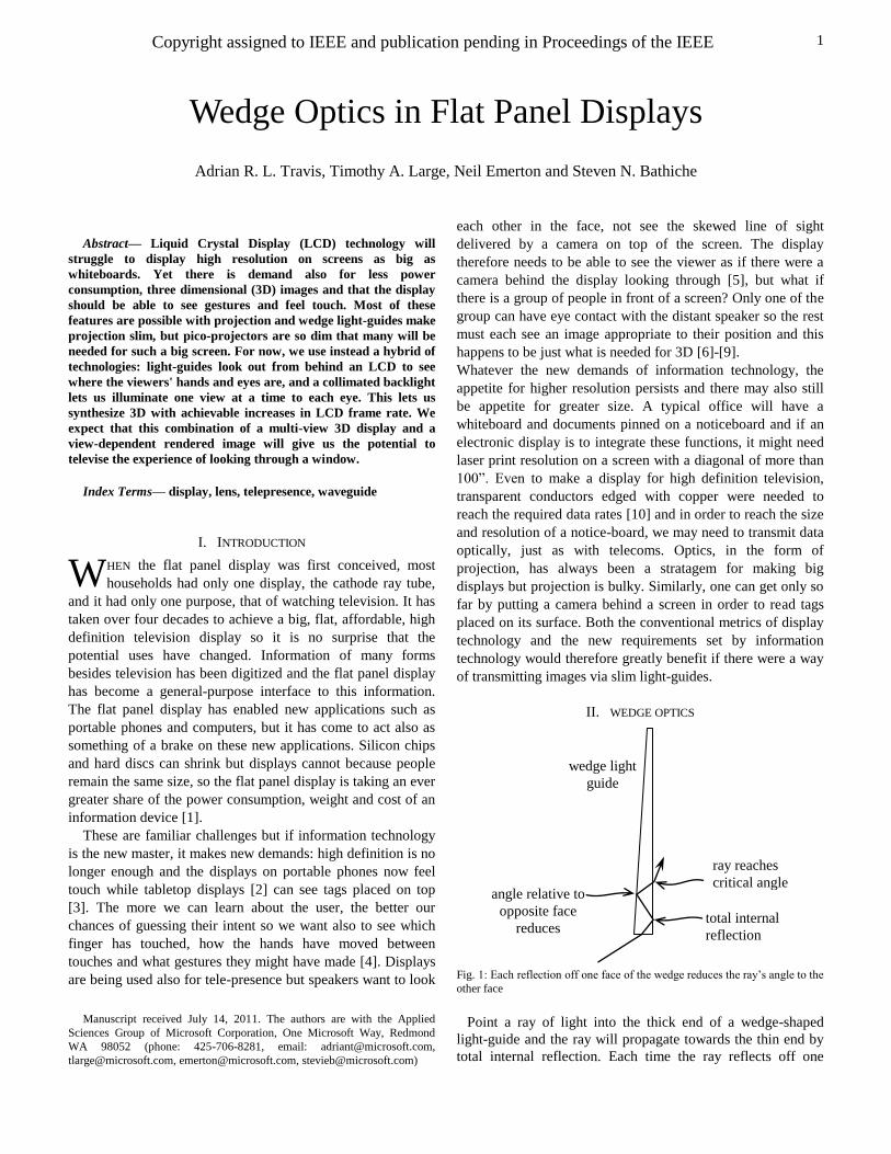
Fig. 1: Each reflection off one face of the wedge reduces the ray’s angle to the
other face
Point a ray of light into the thick end of a wedge-shaped
light-guide and the ray will propagate towards the thin end by
total internal reflection. Each time the ray reflects off one
Wedge Optics in Flat Panel Displays
Adrian R. L. Travis, Timothy A. Large, Neil Emerton and Steven N. Bathiche
W
ray reaches
critical angle
total internal
reflection
angle relative to
opposite face
reduces
wedge light
guide
Copyright assigned to IEEE and publication pending in Proceedings of the IEEE
2
surface of the wedge, its angle with respect to the normal of
the other surface will decrease until the critical angle is
reached, at which point the ray will emerge into air [11] (Fig.
1).
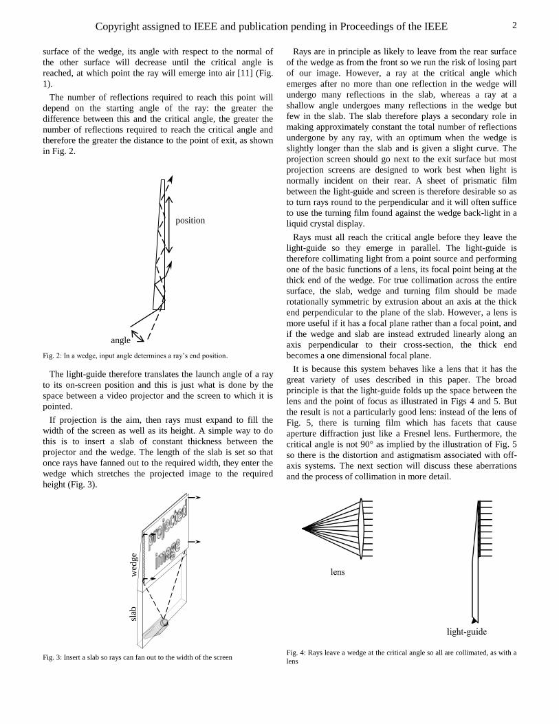
The number of reflections required to reach this point will
depend on the starting angle of the ray: the greater the
difference between this and the critical angle, the greater the
number of reflections required to reach the critical angle and
therefore the greater the distance to the point of exit, as shown
in Fig. 2.
Fig. 2: In a wedge, input angle determines a ray’s end position.
The light-guide therefore translates the launch angle of a ray
to its on-screen position and this is just what is done by the
space between a video projector and the screen to which it is
pointed.
If projection is the aim, then rays must expand to fill the
width of the screen as well as its height. A simple way to do
this is to insert a slab of constant thickness between the
projector and the wedge. The length of the slab is set so that
once rays have fanned out to the required width, they enter the
wedge which stretches the projected image to the required
height (Fig. 3).
Fig. 3: Insert a slab so rays can fan out to the width of the screen
Rays are in principle as likely to leave from the rear surface
of the wedge as from the front so we run the risk of losing part
of our image. However, a ray at the critical angle which
emerges after no more than one reflection in the wedge will
undergo many reflections in the slab, whereas a ray at a
shallow angle undergoes many reflections in the wedge but
few in the slab. The slab therefore plays a secondary role in
making approximately constant the total number of reflections
undergone by any ray, with an optimum when the wedge is
slightly longer than the slab and is given a slight curve. The
projection screen should go next to the exit surface but most
projection screens are designed to work best when light is
normally incident on their rear. A sheet of prismatic film
between the light-guide and screen is therefore desirable so as
to turn rays round to the perpendicular and it will often suffice
to use the turning film found against the wedge back-light in a
liquid crystal display.
Rays must all reach the critical angle before they leave the
light-guide so they emerge in parallel. The light-guide is
therefore collimating light from a point source and performing
one of the basic functions of a lens, its focal point being at the
thick end of the wedge. For true collimation across the entire
surface, the slab, wedge and turning film should be made
rotationally symmetric by extrusion about an axis at the thick
end perpendicular to the plane of the slab. However, a lens is
more useful if it has a focal plane rather than a focal point, and
if the wedge and slab are instead extruded linearly along an
axis perpendicular to their cross-section, the thick end
becomes a one dimensional focal plane.
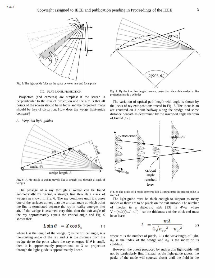
It is because this system behaves like a lens that it has the
great variety of uses described in this paper. The broad
principle is that the light-guide folds up the space between the
lens and the point of focus as illustrated in Figs 4 and 5. But
the result is not a particularly good lens: instead of the lens of
Fig. 5, there is turning film which has facets that cause
aperture diffraction just like a Fresnel lens. Furthermore, the
critical angle is not 90° as implied by the illustration of Fig. 5
so there is the distortion and astigmatism associated with off-
axis systems. The next section will discuss these aberrations
and the process of collimation in more detail.
Fig. 4: Rays leave a wedge at the critical angle so all are collimated, as with a
lens
slab
w
edg
e
position
angle
Copyright assigned to IEEE and publication pending in Proceedings of the IEEE
3
Fig. 5: The light-guide folds up the space between lens and focal plane
III. FLAT PANEL PROJECTION
Projectors (and cameras) are simplest if the screen is
perpendicular to the axis of projection and the aim is that all
points of the screen should be in focus and the projected image
should be free of distortion. How does the wedge light-guide
compare?
A. Very thin light-guides
Fig. 6: A ray inside a wedge travels like a straight ray through a stack of
wedges
The passage of a ray through a wedge can be found
geometrically by tracing a straight line through a stack of
wedges as shown in Fig. 6. The ray continues until it crosses
one of the surfaces at less than the critical angle at which point
the line is terminated because the ray in reality emerges into
air. If the wedge is assumed very thin, then the exit angle of
the ray approximately equals the critical angle and Fig. 6
shows that:
(1)
where L is the length of the wedge, c is the critical angle, is
the starting angle of the ray and X is the distance from the
wedge tip to the point where the ray emerges. If is small,
then it is approximately proportional to X so projection
through the light-guide is approximately linear.
Fig. 7: By the inscribed angle theorem, projection via a thin wedge is like
projection inside a cylinder
The variation of optical path length with angle is shown by
the locus of ray exit positions traced in Fig. 7. The locus is an
arc centered on a point halfway along the wedge and some
distance beneath as determined by the inscribed angle theorem
of Euclid [12].
Fig. 8: The peaks of a mode converge like a spring until the critical angle is
reached
The light-guide must be thick enough to support as many
modes as there are to be pixels on the exit surface. The number
of modes in a dielectric slab
[13] is 4V/ where
V = (t/)(nco2ncl
2)
1/2 so the thickness t of the thick end must
be at least:
(2)
where m is the number of pixels, is the wavelength of light,
nco is the index of the wedge and ncl is the index of its
cladding.
However, the pixels produced by such a thin light-guide will
not be particularly fine. Instead, as the light-guide tapers, the
peaks of the mode will squeeze closer until the field in the
Copyright assigned to IEEE and publication pending in Proceedings of the IEEE
4
cladding switches from evanescence to radiation as shown in
Fig. 8. The mode of a slab wave guide can be thought of as a
pair of counter propagating rays as shown in Fig. 9 and if we
assume that the rear surface is a mirror, the distance p taken
for the modal wavefronts to emerge is:
(3)
Fig. 9: The mode emerges like a pair of counter-propagating rays
Modes will strip out one by one as the waveguide tapers and
if we wish to resolve each pixel, the waveguide must not taper
too steeply and the rate of taper is set by the thick end of the
waveguide where pixels are thickest. If the rate of taper is too
small, however, we run into the problem that some of the light
does not emerge in the manner of Fig. 9 but is reflected so as
to emerge further along the guide. The result is that a faint
duplicate of the projected image appears slightly displaced
from the original and we call this duplicate a ghost image.
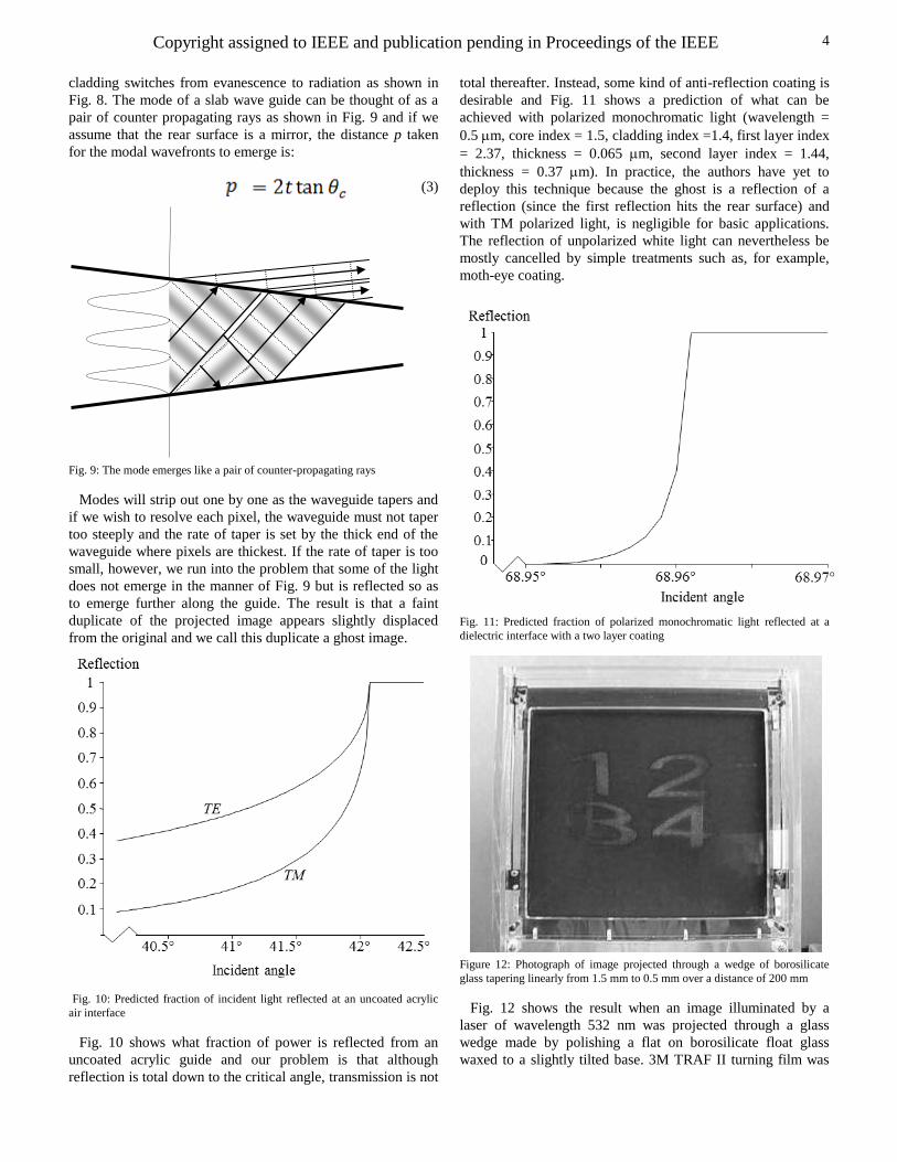
Fig. 10: Predicted fraction of incident light reflected at an uncoated acrylic
air interface
Fig. 10 shows what fraction of power is reflected from an
uncoated acrylic guide and our problem is that although
reflection is total down to the critical angle, transmission is not
total thereafter. Instead, some kind of anti-reflection coating is
desirable and Fig. 11 shows a prediction of what can be
achieved with polarized monochromatic light (wavelength =
0.5 m, core index = 1.5, cladding index =1.4, first layer index
= 2.37, thickness = 0.065 m, second layer index = 1.44,
thickness = 0.37 m). In practice, the authors have yet to
deploy this technique because the ghost is a reflection of a
reflection (since the first reflection hits the rear surface) and
with TM polarized light, is negligible for basic applications.
The reflection of unpolarized white light can nevertheless be
mostly cancelled by simple treatments such as, for example,
moth-eye coating.
Fig. 11: Predicted fraction of polarized monochromatic light reflected at a
dielectric interface with a two layer coating
Figure 12: Photograph of image projected through a wedge of borosilicate
glass tapering linearly from 1.5 mm to 0.5 mm over a distance of 200 mm
Fig. 12 shows the result when an image illuminated by a
laser of wavelength 532 nm was projected through a glass
wedge made by polishing a flat on borosilicate float glass
waxed to a slightly tilted base. 3M TRAF II turning film was
Copyright assigned to IEEE and publication pending in Proceedings of the IEEE
5
placed against the wedge surface with a slight space beneath
and a diffuser on top.
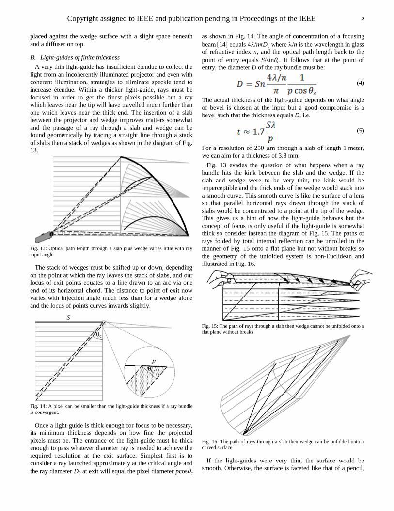
B. Light-guides of finite thickness
A very thin light-guide has insufficient étendue to collect the
light from an incoherently illuminated projector and even with
coherent illumination, strategies to eliminate speckle tend to
increase étendue. Within a thicker light-guide, rays must be
focused in order to get the finest pixels possible but a ray
which leaves near the tip will have travelled much further than
one which leaves near the thick end. The insertion of a slab
between the projector and wedge improves matters somewhat
and the passage of a ray through a slab and wedge can be
found geometrically by tracing a straight line through a stack
of slabs then a stack of wedges as shown in the diagram of Fig.
13.
Fig. 13: Optical path length through a slab plus wedge varies little with ray
input angle
The stack of wedges must be shifted up or down, depending
on the point at which the ray leaves the stack of slabs, and our
locus of exit points equates to a line drawn to an arc via one
end of its horizontal chord. The distance to point of exit now
varies with injection angle much less than for a wedge alone
and the locus of points curves inwards slightly.
Fig. 14: A pixel can be smaller than the light-guide thickness if a ray bundle
is convergent.
Once a light-guide is thick enough for focus to be necessary,
its minimum thickness depends on how fine the projected
pixels must be. The entrance of the light-guide must be thick
enough to pass whatever diameter ray is needed to achieve the
required resolution at the exit surface. Simplest first is to
consider a ray launched approximately at the critical angle and
the ray diameter D0 at exit will equal the pixel diameter pcosc
as shown in Fig. 14. The angle of concentration of a focusing
beam [14] equals 4/nD0 where /n is the wavelength in glass
of refractive index n, and the optical path length back to the
point of entry equals S/sinc. It follows that at the point of
entry, the diameter D of the ray bundle must be:
(4)
The actual thickness of the light-guide depends on what angle
of bevel is chosen at the input but a good compromise is a
bevel such that the thickness equals D, i.e.
(5)
For a resolution of 250 m through a slab of length 1 meter,
we can aim for a thickness of 3.8 mm.
Fig. 13 evades the question of what happens when a ray
bundle hits the kink between the slab and the wedge. If the
slab and wedge were to be very thin, the kink would be
imperceptible and the thick ends of the wedge would stack into
a smooth curve. This smooth curve is like the surface of a lens
so that parallel horizontal rays drawn through the stack of
slabs would be concentrated to a point at the tip of the wedge.
This gives us a hint of how the light-guide behaves but the
concept of focus is only useful if the light-guide is somewhat
thick so consider instead the diagram of Fig. 15. The paths of
rays folded by total internal reflection can be unrolled in the
manner of Fig. 15 onto a flat plane but not without breaks so
the geometry of the unfolded system is non-Euclidean and
illustrated in Fig. 16.
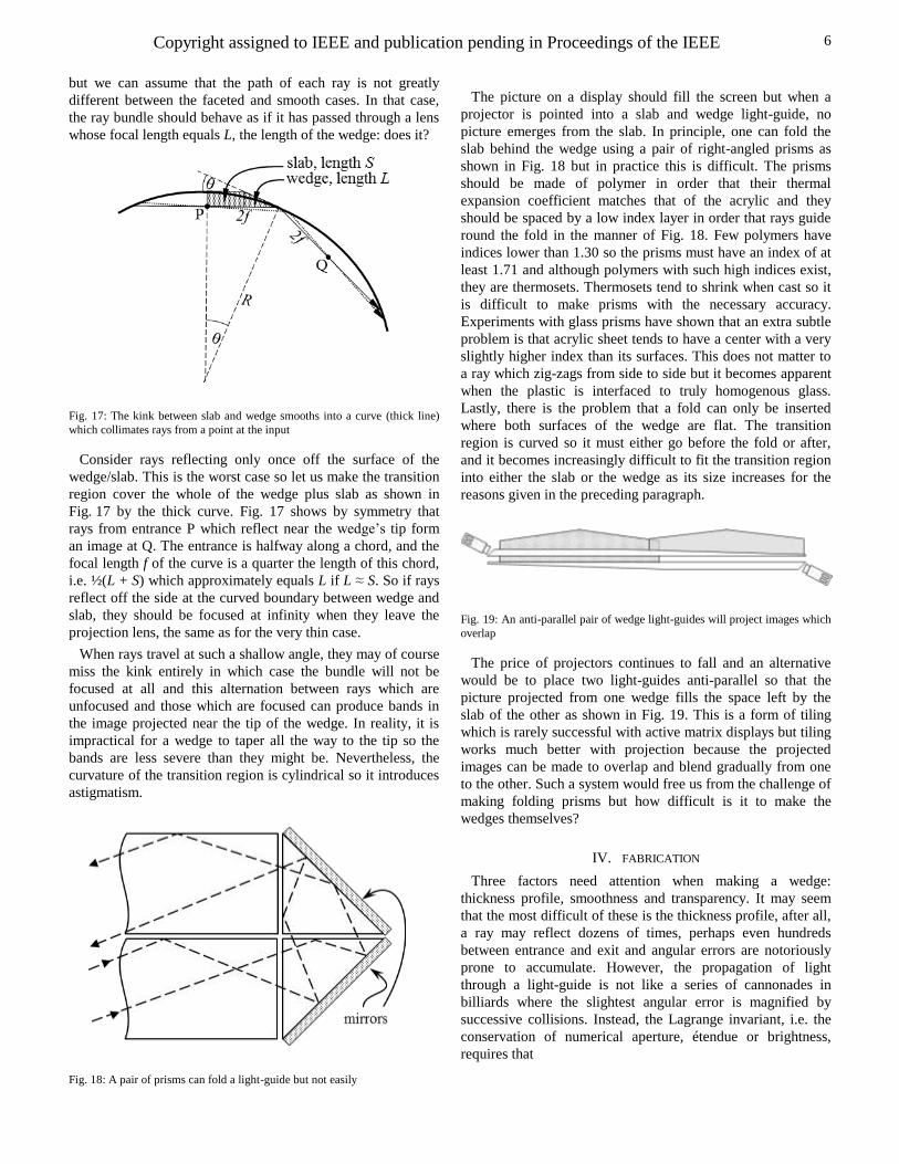
Fig. 15: The path of rays through a slab then wedge cannot be unfolded onto a
flat plane without breaks
Fig. 16: The path of rays through a slab then wedge can be unfolded onto a
curved surface
If the light-guides were very thin, the surface would be
smooth. Otherwise, the surface is faceted like that of a pencil,
Copyright assigned to IEEE and publication pending in Proceedings of the IEEE
6
but we can assume that the path of each ray is not greatly
different between the faceted and smooth cases. In that case,
the ray bundle should behave as if it has passed through a lens
whose focal length equals L, the length of the wedge: does it?
Fig. 17: The kink between slab and wedge smooths into a curve (thick line)
which collimates rays from a point at the input
Consider rays reflecting only once off the surface of the
wedge/slab. This is the worst case so let us make the transition
region cover the whole of the wedge plus slab as shown in
Fig. 17 by the thick curve. Fig. 17 shows by symmetry that
rays from entrance P which reflect near the wedge’s tip form
an image at Q. The entrance is halfway along a chord, and the
focal length f of the curve is a quarter the length of this chord,
i.e. ½(L + S) which approximately equals L if L ≈ S. So if rays
reflect off the side at the curved boundary between wedge and
slab, they should be focused at infinity when they leave the
projection lens, the same as for the very thin case.
When rays travel at such a shallow angle, they may of course
miss the kink entirely in which case the bundle will not be
focused at all and this alternation between rays which are
unfocused and those which are focused can produce bands in
the image projected near the tip of the wedge. In reality, it is
impractical for a wedge to taper all the way to the tip so the
bands are less severe than they might be. Nevertheless, the
curvature of the transition region is cylindrical so it introduces
astigmatism.
Fig. 18: A pair of prisms can fold a light-guide but not easily
The picture on a display should fill the screen but when a
projector is pointed into a slab and wedge light-guide, no
picture emerges from the slab. In principle, one can fold the
slab behind the wedge using a pair of right-angled prisms as
shown in Fig. 18 but in practice this is difficult. The prisms
should be made of polymer in order that their thermal
expansion coefficient matches that of the acrylic and they
should be spaced by a low index layer in order that rays guide
round the fold in the manner of Fig. 18. Few polymers have
indices lower than 1.30 so the prisms must have an index of at
least 1.71 and although polymers with such high indices exist,
they are thermosets. Thermosets tend to shrink when cast so it
is difficult to make prisms with the necessary accuracy.
Experiments with glass prisms have shown that an extra subtle
problem is that acrylic sheet tends to have a center with a very
slightly higher index than its surfaces. This does not matter to
a ray which zig-zags from side to side but it becomes apparent
when the plastic is interfaced to truly homogenous glass.
Lastly, there is the problem that a fold can only be inserted
where both surfaces of the wedge are flat. The transition
region is curved so it must either go before the fold or after,
and it becomes increasingly difficult to fit the transition region
into either the slab or the wedge as its size increases for the
reasons given in the preceding paragraph.
Fig. 19: An anti-parallel pair of wedge light-guides will project images which
overlap
The price of projectors continues to fall and an alternative
would be to place two light-guides anti-parallel so that the
picture projected from one wedge fills the space left by the
slab of the other as shown in Fig. 19. This is a form of tiling
which is rarely successful with active matrix displays but tiling
works much better with projection because the projected
images can be made to overlap and blend gradually from one
to the other. Such a system would free us from the challenge of
making folding prisms but how difficult is it to make the
wedges themselves?
IV. FABRICATION
Three factors need attention when making a wedge:
thickness profile, smoothness and transparency. It may seem
that the most difficult of these is the thickness profile, after all,
a ray may reflect dozens of times, perhaps even hundreds
between entrance and exit and angular errors are notoriously
prone to accumulate. However, the propagation of light
through a light-guide is not like a series of cannonades in
billiards where the slightest angular error is magnified by
successive collisions. Instead, the Lagrange invariant, i.e. the
conservation of numerical aperture, étendue or brightness,
requires that
Copyright assigned to IEEE and publication pending in Proceedings of the IEEE
7
(6)
where t is the thickness of the light-guide and is ray angle.
This means that if the thickness of the light-guide is slightly
different from that specified at one point, behavior at the rest
of the light-guide will be unaffected provided that the bump or
dip is gentle. It also gives us a simple way of determining
approximately where a ray leaves a light-guide. For a ray
launched at angle into a guide whose starting thickness is t0
then the ray will leave when guide thickness equals tc where:
0 (7)
We can think of tc as the critical thickness for a ray, and the
light-guide surfaces can undulate at random provided that the
thickness is greater than tc until that point where the ray is to
emerge. Errors in thickness therefore translate directly to
errors in pixel position, so if our target is that the projected
image have a distortion of less than 1%, then the thickness of
the light-guide at any point must deviate by no more than 1%
from specification. This happens to be approximately equal to
the shrinkage of plastic as it leaves an injection molding
machine whereas if the light-guide is to be machined with a 1
mm thick slab, the thickness tolerance is 10 m. Many
machine tools are accurate to this tolerance if well maintained.
Once the wedge profile has been machined, it must be made
much smoother than standard optical surfaces because the ray
reflects of the surface so many times. The residual roughness
will partially scatter a ray and the total integrated scatter (TIS)
off an opaque surface is given by [15]:
TIS
(8)
where σ is the root-mean-square roughness, i is the angle of
incidence and λ is the wavelength. Many ray-tracing programs
use this equation also for a dielectric interface and it is a good
approximation but the index difference across the interface has
an effect. The rigorous analysis is too long for inclusion in this
paper but a good target is that the surfaces should have a
roughness average of 1 nm or less. It should be emphasized
that this is a specification for roughness, not flatness, and there
is no need for the surfaces to be especially flat because
curvature on one side of a light-guide is all but cancelled out
by equal curvature on the other. Nevertheless, glass optical
components are typically polished to a smoothness of 2 or 3
nm and plastics, being soft, are more difficult to polish than
glass.
It is astonishingly fortunate that cast acrylic, which is the
most transparent off-the-shelf sheet, is also so affordable, so
easily machined and so smooth. The smoothness arises
because the sheet is usually formed by polymerizing the
monomer between sheets of float glass which themselves
typically have a roughness of as little as 0.1 nm because they
are the frozen surface of a liquid. The un-machined surface
therefore needs no further treatment, indeed it is important that
the protective film be left on this surface until the last possible
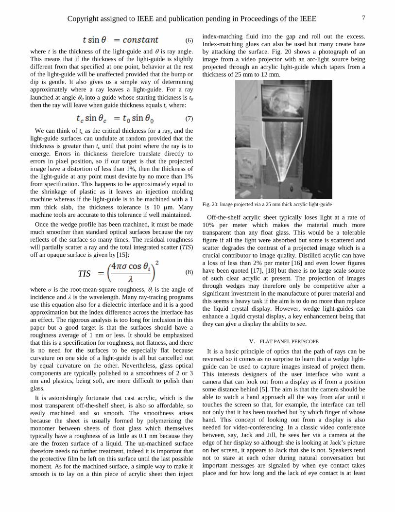
moment. As for the machined surface, a simple way to make it
smooth is to lay on a thin piece of acrylic sheet then inject
index-matching fluid into the gap and roll out the excess.
Index-matching glues can also be used but many create haze
by attacking the surface. Fig. 20 shows a photograph of an
image from a video projector with an arc-light source being
projected through an acrylic light-guide which tapers from a
thickness of 25 mm to 12 mm.
Fig. 20: Image projected via a 25 mm thick acrylic light-guide
Off-the-shelf acrylic sheet typically loses light at a rate of
10% per meter which makes the material much more
transparent than any float glass. This would be a tolerable
figure if all the light were absorbed but some is scattered and
scatter degrades the contrast of a projected image which is a
crucial contributor to image quality. Distilled acrylic can have
a loss of less than 2% per meter [16] and even lower figures
have been quoted [17], [18] but there is no large scale source
of such clear acrylic at present. The projection of images
through wedges may therefore only be competitive after a
significant investment in the manufacture of purer material and
this seems a heavy task if the aim is to do no more than replace
the liquid crystal display. However, wedge light-guides can
enhance a liquid crystal display, a key enhancement being that
they can give a display the ability to see.
V. FLAT PANEL PERISCOPE
It is a basic principle of optics that the path of rays can be
reversed so it comes as no surprise to learn that a wedge light-
guide can be used to capture images instead of project them.
This interests designers of the user interface who want a
camera that can look out from a display as if from a position
some distance behind [5]. The aim is that the camera should be
able to watch a hand approach all the way from afar until it
touches the screen so that, for example, the interface can tell
not only that it has been touched but by which finger of whose
hand. This concept of looking out from a display is also
needed for video-conferencing. In a classic video conference
between, say, Jack and Jill, he sees her via a camera at the
edge of her display so although she is looking at Jack’s picture
on her screen, it appears to Jack that she is not. Speakers tend
not to stare at each other during natural conversation but
important messages are signaled by when eye contact takes
place and for how long and the lack of eye contact is at least
Copyright assigned to IEEE and publication pending in Proceedings of the IEEE
8
one good reason why video-conferencing has yet to become
commonplace.
Alternatives to light-guides have been tried, for example one
can scatter cameras around the edge of a flat panel display and
interpolate the view in between [19], [20] but this is hard
because we are so perceptive to where eyes are looking. A
second approach is to have a displayed-sized array of cameras
[21] which might be put behind a transparent display but cost
aside, the cameras would need enormous depth of field to
detect both touch and distant objects. Photo-sensors have been
integrated into the backplane of LCDs [22], [23] but without
lenses these detect only shadow and a lens small enough to fit
between the pixels of a LCD is little better than a pin-hole
camera. The LCD itself can be used as a mask like that of an
X-ray telescope [24] but again, the resolution is limited by pin-
hole diffraction
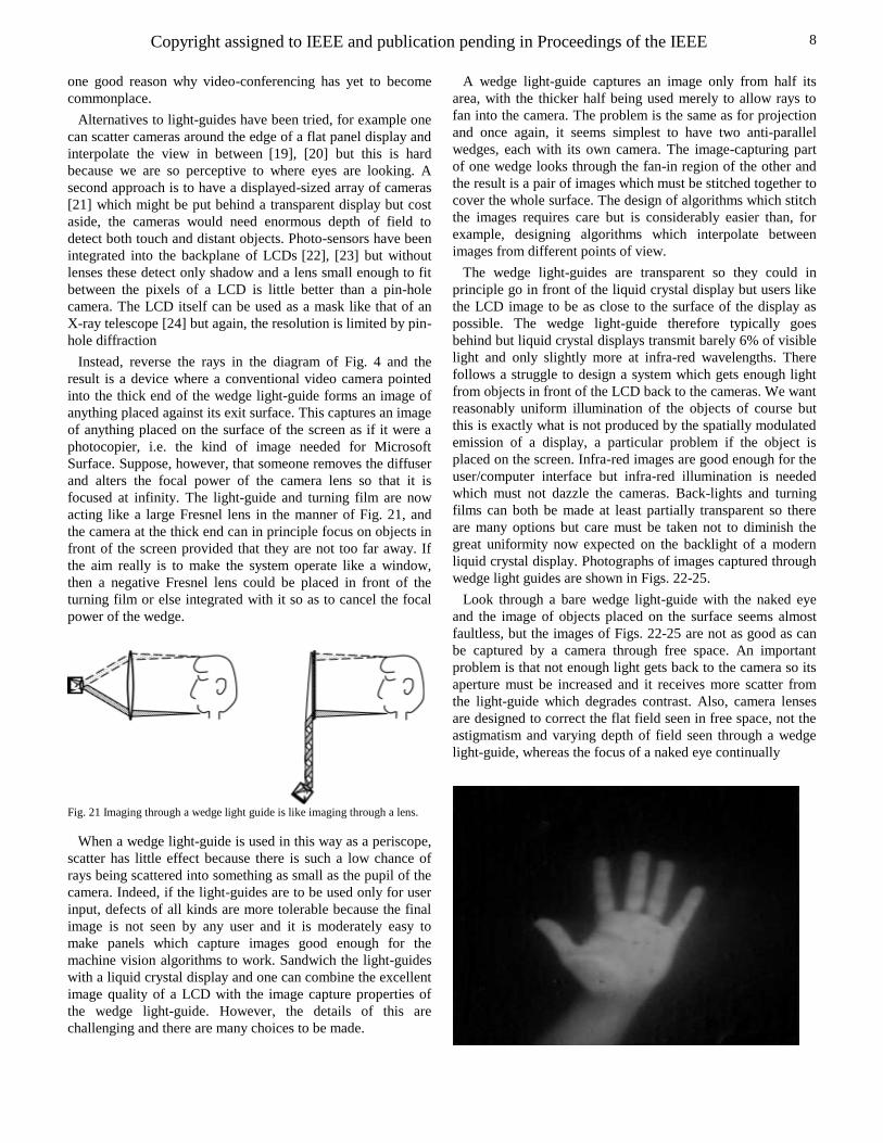
Instead, reverse the rays in the diagram of Fig. 4 and the
result is a device where a conventional video camera pointed
into the thick end of the wedge light-guide forms an image of
anything placed against its exit surface. This captures an image
of anything placed on the surface of the screen as if it were a
photocopier, i.e. the kind of image needed for Microsoft
Surface. Suppose, however, that someone removes the diffuser
and alters the focal power of the camera lens so that it is
focused at infinity. The light-guide and turning film are now
acting like a large Fresnel lens in the manner of Fig. 21, and
the camera at the thick end can in principle focus on objects in
front of the screen provided that they are not too far away. If
the aim really is to make the system operate like a window,
then a negative Fresnel lens could be placed in front of the
turning film or else integrated with it so as to cancel the focal
power of the wedge.
Fig. 21 Imaging through a wedge light guide is like imaging through a lens.
When a wedge light-guide is used in this way as a periscope,
scatter has little effect because there is such a low chance of
rays being scattered into something as small as the pupil of the
camera. Indeed, if the light-guides are to be used only for user
input, defects of all kinds are more tolerable because the final
image is not seen by any user and it is moderately easy to
make panels which capture images good enough for the
machine vision algorithms to work. Sandwich the light-guides
with a liquid crystal display and one can combine the excellent
image quality of a LCD with the image capture properties of
the wedge light-guide. However, the details of this are
challenging and there are many choices to be made.
A wedge light-guide captures an image only from half its
area, with the thicker half being used merely to allow rays to
fan into the camera. The problem is the same as for projection
and once again, it seems simplest to have two anti-parallel
wedges, each with its own camera. The image-capturing part
of one wedge looks through the fan-in region of the other and
the result is a pair of images which must be stitched together to
cover the whole surface. The design of algorithms which stitch
the images requires care but is considerably easier than, for
example, designing algorithms which interpolate between
images from different points of view.
The wedge light-guides are transparent so they could in
principle go in front of the liquid crystal display but users like
the LCD image to be as close to the surface of the display as
possible. The wedge light-guide therefore typically goes
behind but liquid crystal displays transmit barely 6% of visible
light and only slightly more at infra-red wavelengths. There
follows a struggle to design a system which gets enough light
from objects in front of the LCD back to the cameras. We want
reasonably uniform illumination of the objects of course but
this is exactly what is not produced by the spatially modulated
emission of a display, a particular problem if the object is
placed on the screen. Infra-red images are good enough for the
user/computer interface but infra-red illumination is needed
which must not dazzle the cameras. Back-lights and turning
films can both be made at least partially transparent so there
are many options but care must be taken not to diminish the
great uniformity now expected on the backlight of a modern
liquid crystal display. Photographs of images captured through
wedge light guides are shown in Figs. 22-25.
Look through a bare wedge light-guide with the naked eye
and the image of objects placed on the surface seems almost
faultless, but the images of Figs. 22-25 are not as good as can
be captured by a camera through free space. An important
problem is that not enough light gets back to the camera so its
aperture must be increased and it receives more scatter from
the light-guide which degrades contrast. Also, camera lenses
are designed to correct the flat field seen in free space, not the
astigmatism and varying depth of field seen through a wedge
light-guide, whereas the focus of a naked eye continually
Copyright assigned to IEEE and publication pending in Proceedings of the IEEE
9
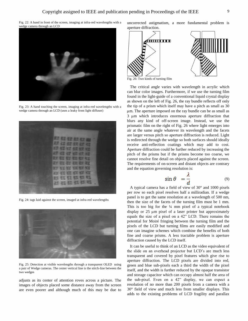
Fig. 22: A hand in front of the screen, imaging at infra-red wavelengths with a
wedge camera through an LCD
Fig. 23: A hand touching the screen, imaging at infra-red wavelengths with a
wedge camera through an LCD (uses a leaky front light diffuser)
Fig. 24: tags laid against the screen, imaged at infra-red wavelengths
Fig. 25: Detection at visible wavelengths through a transparent OLED using
a pair of Wedge cameras. The center vertical line is the stitch-line between the
two wedges
adjusts as its center of attention roves across a picture. The
images of objects placed some distance away from the screen
are even poorer and although much of this may be due to
uncorrected astigmatism, a more fundamental problem is
aperture diffraction.
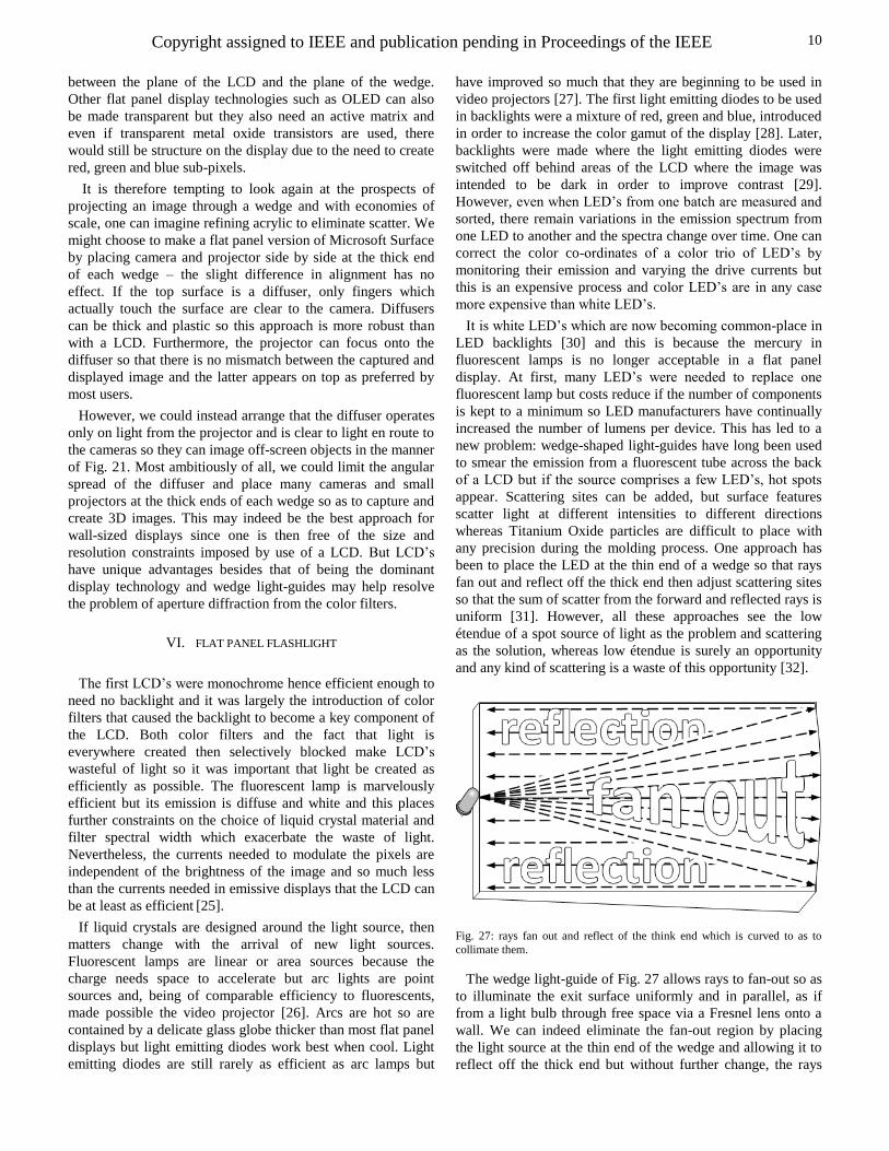
Fig. 26: Two kinds of turning film
The critical angle varies with wavelength in acrylic which
can blur color images. Furthermore, if we use the turning film
found in the light-guide of a conventional liquid crystal display
as shown on the left of Fig. 26, the ray bundle reflects off only
the tip of a prism which itself may have a pitch as small as 30
m. The aperture imposed on the ray bundle can be as small as
3 m which introduces enormous aperture diffraction that
blurs any kind of off-screen image. Instead, we use the
prismatic film on the right of Fig. 26 where light emerges into
air at the same angle whatever its wavelength and the facets
are larger versus pitch so aperture diffraction is reduced. Light
is redirected through the wedge so both surfaces should ideally
receive anti-reflection coatings which may add to cost.
Aperture diffraction could be further reduced by increasing the
pitch of the prisms but if the prisms become too coarse, we
cannot resolve fine detail on objects placed against the screen.
The requirements of on-screen and distant objects are contrary
and the equation governing resolution is:
(9)
A typical camera has a field of view of 30° and 1000 pixels
per row so each pixel resolves half a milliradian. If a wedge
panel is to get the same resolution at a wavelength of 500 nm,
then the size of the facets of the turning film must be 1 mm.
This is too big for the ¼ mm pixel of a typical notebook
display or 25 m pixel of a laser printer but approximately
equals the size of a pixel on a 42” LCD. There remains the
potential for Moiré fringing between the turning film and the
pixels of the LCD but turning films are easily modified and
one can imagine schemes which combine the benefits of both
fine and coarse prisms. A less tractable problem is aperture
diffraction caused by the LCD itself.
It can be useful to think of an LCD as the video equivalent of
the slide on an overhead projector but LCD’s are much less
transparent and covered by pixel features which give rise to
aperture diffraction. The LCD pixels are divided into red,
green and blue sub-pixels each a third the width of the pixel
itself, and the width is further reduced by the opaque transistor
and storage capacitor which can occupy almost half the area of
the sub-pixel. Even on a 42” display, we can expect a
resolution of no more than 200 pixels from a camera with a
30° field of view and much less from smaller displays. This
adds to the existing problems of LCD fragility and parallax
Copyright assigned to IEEE and publication pending in Proceedings of the IEEE
10
between the plane of the LCD and the plane of the wedge.
Other flat panel display technologies such as OLED can also
be made transparent but they also need an active matrix and
even if transparent metal oxide transistors are used, there
would still be structure on the display due to the need to create
red, green and blue sub-pixels.
It is therefore tempting to look again at the prospects of
projecting an image through a wedge and with economies of
scale, one can imagine refining acrylic to eliminate scatter. We
might choose to make a flat panel version of Microsoft Surface
by placing camera and projector side by side at the thick end
of each wedge – the slight difference in alignment has no
effect. If the top surface is a diffuser, only fingers which
actually touch the surface are clear to the camera. Diffusers
can be thick and plastic so this approach is more robust than
with a LCD. Furthermore, the projector can focus onto the
diffuser so that there is no mismatch between the captured and
displayed image and the latter appears on top as preferred by
most users.
However, we could instead arrange that the diffuser operates
only on light from the projector and is clear to light en route to
the cameras so they can image off-screen objects in the manner
of Fig. 21. Most ambitiously of all, we could limit the angular
spread of the diffuser and place many cameras and small
projectors at the thick ends of each wedge so as to capture and
create 3D images. This may indeed be the best approach for
wall-sized displays since one is then free of the size and
resolution constraints imposed by use of a LCD. But LCD’s
have unique advantages besides that of being the dominant
display technology and wedge light-guides may help resolve
the problem of aperture diffraction from the color filters.
VI. FLAT PANEL FLASHLIGHT
The first LCD’s were monochrome hence efficient enough to
need no backlight and it was largely the introduction of color
filters that caused the backlight to become a key component of
the LCD. Both color filters and the fact that light is
everywhere created then selectively blocked make LCD’s
wasteful of light so it was important that light be created as
efficiently as possible. The fluorescent lamp is marvelously
efficient but its emission is diffuse and white and this places
further constraints on the choice of liquid crystal material and
filter spectral width which exacerbate the waste of light.
Nevertheless, the currents needed to modulate the pixels are
independent of the brightness of the image and so much less
than the currents needed in emissive displays that the LCD can
be at least as efficient [25].
If liquid crystals are designed around the light source, then
matters change with the arrival of new light sources.
Fluorescent lamps are linear or area sources because the
charge needs space to accelerate but arc lights are point
sources and, being of comparable efficiency to fluorescents,
made possible the video projector [26]. Arcs are hot so are
contained by a delicate glass globe thicker than most flat panel
displays but light emitting diodes work best when cool. Light
emitting diodes are still rarely as efficient as arc lamps but
have improved so much that they are beginning to be used in
video projectors [27]. The first light emitting diodes to be used
in backlights were a mixture of red, green and blue, introduced
in order to increase the color gamut of the display [28]. Later,
backlights were made where the light emitting diodes were
switched off behind areas of the LCD where the image was
intended to be dark in order to improve contrast [29].
However, even when LED’s from one batch are measured and
sorted, there remain variations in the emission spectrum from
one LED to another and the spectra change over time. One can
correct the color co-ordinates of a color trio of LED’s by
monitoring their emission and varying the drive currents but
this is an expensive process and color LED’s are in any case
more expensive than white LED’s.
It is white LED’s which are now becoming common-place in
LED backlights [30] and this is because the mercury in
fluorescent lamps is no longer acceptable in a flat panel
display. At first, many LED’s were needed to replace one
fluorescent lamp but costs reduce if the number of components
is kept to a minimum so LED manufacturers have continually
increased the number of lumens per device. This has led to a
new problem: wedge-shaped light-guides have long been used
to smear the emission from a fluorescent tube across the back
of a LCD but if the source comprises a few LED’s, hot spots
appear. Scattering sites can be added, but surface features
scatter light at different intensities to different directions
whereas Titanium Oxide particles are difficult to place with
any precision during the molding process. One approach has
been to place the LED at the thin end of a wedge so that rays
fan out and reflect off the thick end then adjust scattering sites
so that the sum of scatter from the forward and reflected rays is
uniform [31]. However, all these approaches see the low
étendue of a spot source of light as the problem and scattering
as the solution, whereas low étendue is surely an opportunity
and any kind of scattering is a waste of this opportunity [32].
Fig. 27: rays fan out and reflect of the think end which is curved to as to
collimate them.
The wedge light-guide of Fig. 27 allows rays to fan-out so as
to illuminate the exit surface uniformly and in parallel, as if
from a light bulb through free space via a Fresnel lens onto a
wall. We can indeed eliminate the fan-out region by placing
the light source at the thin end of the wedge and allowing it to
reflect off the thick end but without further change, the rays
Copyright assigned to IEEE and publication pending in Proceedings of the IEEE
11
will return to the thin end without leaving the waveguide.
Instead consider first our aim, that rays should hit the whole of
the exit surface in parallel with uniform intensity, and trace
these rays backwards through the system. We wish that the
rays should emanate from a point and Fig. 27 shows that from
a view perpendicular to the plane of the light-guide, the thick
end should have a radius of curvature equal to half the length
of the light-guide.
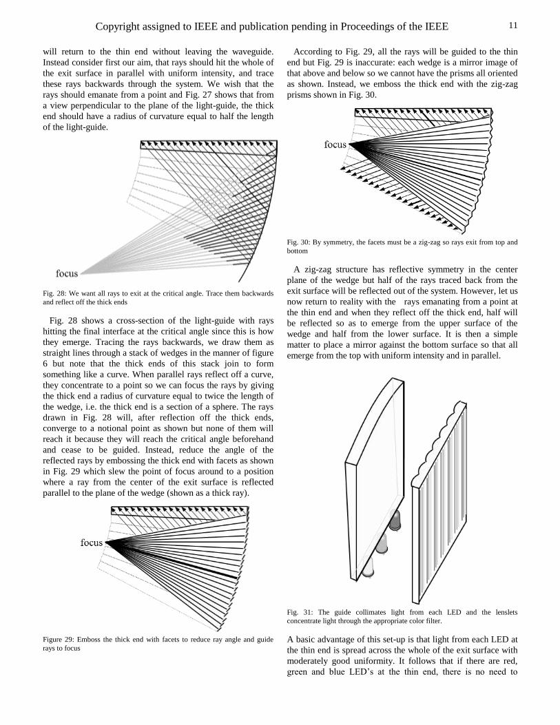
Fig. 28: We want all rays to exit at the critical angle. Trace them backwards
and reflect off the thick ends
Fig. 28 shows a cross-section of the light-guide with rays
hitting the final interface at the critical angle since this is how
they emerge. Tracing the rays backwards, we draw them as
straight lines through a stack of wedges in the manner of figure
6 but note that the thick ends of this stack join to form
something like a curve. When parallel rays reflect off a curve,
they concentrate to a point so we can focus the rays by giving
the thick end a radius of curvature equal to twice the length of
the wedge, i.e. the thick end is a section of a sphere. The rays
drawn in Fig. 28 will, after reflection off the thick ends,
converge to a notional point as shown but none of them will
reach it because they will reach the critical angle beforehand
and cease to be guided. Instead, reduce the angle of the
reflected rays by embossing the thick end with facets as shown
in Fig. 29 which slew the point of focus around to a position
where a ray from the center of the exit surface is reflected
parallel to the plane of the wedge (shown as a thick ray).
Figure 29: Emboss the thick end with facets to reduce ray angle and guide
rays to focus
According to Fig. 29, all the rays will be guided to the thin
end but Fig. 29 is inaccurate: each wedge is a mirror image of
that above and below so we cannot have the prisms all oriented
as shown. Instead, we emboss the thick end with the zig-zag
prisms shown in Fig. 30.
Fig. 30: By symmetry, the facets must be a zig-zag so rays exit from top and
bottom
A zig-zag structure has reflective symmetry in the center
plane of the wedge but half of the rays traced back from the
exit surface will be reflected out of the system. However, let us
now return to reality with the rays emanating from a point at
the thin end and when they reflect off the thick end, half will
be reflected so as to emerge from the upper surface of the
wedge and half from the lower surface. It is then a simple
matter to place a mirror against the bottom surface so that all
emerge from the top with uniform intensity and in parallel.
Fig. 31: The guide collimates light from each LED and the lenslets
concentrate light through the appropriate color filter.
A basic advantage of this set-up is that light from each LED at
the thin end is spread across the whole of the exit surface with
moderately good uniformity. It follows that if there are red,
green and blue LED’s at the thin end, there is no need to
Copyright assigned to IEEE and publication pending in Proceedings of the IEEE
12
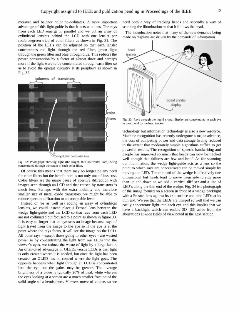
measure and balance color co-ordinates. A more important
advantage of this light-guide is that it acts as a lens. The rays
from each LED emerge in parallel and we put an array of
cylindrical lenslets behind the LCD with one lenslet per
red/blue/green triad of color filters as shown in Fig. 31. The
position of the LEDs can be adjusted so that each lenslet
concentrates red light through the red filter, green light
through the green filter and blue through blue. This reduces the
power consumption by a factor of almost three and perhaps
more if the light were to be concentrated through each filter so
as to avoid the opaque circuitry at its periphery as shown in
Fig. 32.
Fig. 32: Photograph showing light (the bright, thin horizontal lines) being
concentrated through the center of each color filter.
Of course this means that there may no longer be any need
for color filters but the benefit here is not only one of less cost.
Color filters are the major cause of aperture diffraction with
images seen through an LCD and that caused by transistors is
much less. Perhaps with the extra mobility and therefore
smaller size of metal oxide transistors, we might be able to
reduce aperture diffraction to an acceptable level.
Instead of (or as well as) adding an array of cylindrical
lenslets, we could instead place a Fresnel lens between the
wedge light-guide and the LCD so that rays from each LED
are not collimated but focused to a point as shown in figure 33.
It is easy to forget that an eye sees an image because rays of
light travel from the image to the eye so if the eye is at the
point where the rays focus, it will see the image on the LCD.
All other rays - except those going to other eyes - are wasted
power so by concentrating the light from our LEDs into the
viewer’s eyes, we reduce the waste of light by a large factor.
An often-cited advantage of OLEDs versus LCDs is that light
is only created where it is needed, but once the light has been
created, an OLED has no control where the light goes. The
opposite happens when light through an LCD is concentrated
into the eye but the gains may be greater. The average
brightness of a video is typically 20% of peak white whereas
the eyes looking at a screen are a much smaller fraction of the
solid angle of a hemisphere. Viewers move of course, so we
need both a way of tracking heads and secondly a way of
scanning the illumination so that it follows the head.
The introduction notes that many of the new demands being
made on displays are driven by the demands of information
Fig. 33: Rays through the liquid crystal display are concentrated to each eye
in turn found by the head tracker
technology but information technology is also a new resource.
Machine recognition has recently undergone a major advance,
the cost of computing power and data storage having reduced
to the extent that moderately simple algorithms suffice to get
powerful results. The recognition of speech, handwriting and
people has improved so much that heads can now be tracked
well enough that failures are few and brief. As for scanning
our illumination, the wedge light-guide acts as a lens so the
point to which rays are concentrated can be moved simply by
moving the LED. The thin end of the wedge is effectively one
dimensional but heads tend to move from side to side more
than up and down so we add a vertical diffuser and a line of
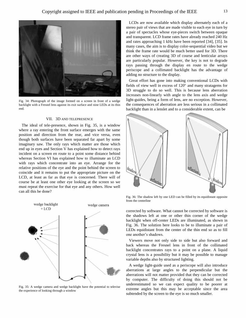
LED’s along the thin end of the wedge. Fig. 34 is a photograph
of the image formed on a screen in front of a wedge backlight
with a Fresnel lens against its exit surface and nine LEDs at its
thin end. We see that the LEDs are imaged so well that we can
easily concentrate light into each eye and this implies that we
have a backlight which can enable 3D [33] aside from the
aberrations at wide fields of view noted in the next section.
Copyright assigned to IEEE and publication pending in Proceedings of the IEEE
13
Fig. 34: Photograph of the image formed on a screen in front of a wedge
backlight with a Fresnel lens against its exit surface and nine LEDs at its thin
end.
VII. 3D AND TELEPRESENCE
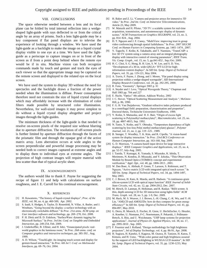
The ideal of tele-presence, shown in Fig. 35, is a window
where a ray entering the front surface emerges with the same
position and direction from the rear, and vice versa, even
though both surfaces have been separated far apart by some
imaginary saw. The only rays which matter are those which
end up in eyes and Section V has explained how to detect rays
incident on a screen en route to a point some distance behind
whereas Section VI has explained how to illuminate an LCD
with rays which concentrate into an eye. Arrange for the
relative positions of the eye and the point behind the screen to
coincide and it remains to put the appropriate picture on the
LCD, at least as far as that eye is concerned. There will of
course be at least one other eye looking at the screen so we
must repeat the exercise for that eye and any others. How well
can all this be done?
Fig. 35: A wedge camera and wedge backlight have the potential to televise
the experience of looking through a window
LCDs are now available which display alternately each of a
stereo pair of views that are made visible to each eye in turn by
a pair of spectacles whose eye-pieces switch between opaque
and transparent. LCD frame rates have already reached 240 Hz
and rates approaching 1 kHz have been reported [34], [35]. In
many cases, the aim is to display color-sequential video but we
think the frame rate would be much better used for 3D. There
are other ways of creating 3D of course and lenticular arrays
are particularly popular. However, the key is not to degrade
rays passing through the display en route to the wedge
periscope and a collimated backlight has the advantage of
adding no structure to the display.
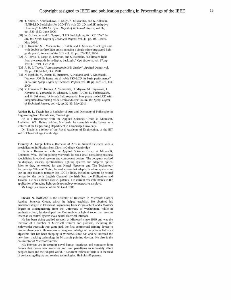
Great effort has gone into making conventional LCDs with
fields of view well in excess of 120 and many stratagems for
3D struggle to do so well. This is because lens aberration
increases non-linearly with angle to the lens axis and wedge
light-guides, being a form of lens, are no exception. However,
the consequences of aberration are less serious in a collimated
backlight than in a lenslet and to a considerable extent, can be
Fig. 36: The shadow left by one LED can be filled by its equidistant opposite
from the centerline
corrected by software. What cannot be corrected by software is
the shadows left at one or other thin corner of the wedge
backlight when off-center LEDs are illuminated, as shown in
Fig. 36. The solution here looks to be to illuminate a pair of
LEDs equidistant from the center of the thin end so as to fill
one another’s shadows.
Viewers move not only side to side but also forward and
back whereas the Fresnel lens in front of the collimated
backlight concentrates rays to a point on a plane. A liquid
crystal lens is a possibility but it may be possible to manage
variable depths also by structured lighting.
A wedge light-guide used as a periscope will also introduce
aberrations at large angles to the perpendicular but the
aberrations will not matter provided that they can be corrected
by computer. The difficulty of doing this should not be
underestimated so we can expect quality to be poorer at
extreme angles but this may be acceptable since the area
subtended by the screen to the eye is so much smaller.
Copyright assigned to IEEE and publication pending in Proceedings of the IEEE
14
VIII. CONCLUSIONS
The space otherwise needed between a lens and its focal
plane can be folded by total internal reflection into a wedge-
shaped light-guide with rays deflected to or from the critical
angle by an array of prisms. Such a lens light-guide may be a
key component if flat panel displays are to televise the
experience of looking through a window. We have used the
light-guide as a backlight to make the image on a liquid crystal
display visible to one eye at a time. We have used the light-
guide as a periscope to capture images on or in front of the
screen as if from a point deep behind where the remote eye
would be if in situ. Machine vision can both recognize
commands made by touch and gesture and track the eyes of
each viewer so that the appropriate image may be captured on
the remote screen and displayed to the related eye on the local
screen.
We have used the system to display 3D without the need for
spectacles and the backlight draws a fraction of the power
needed when the illumination is diffuse. Power consumption
therefore need not constrain the size of liquid crystal displays
which may affordably increase with the elimination of color
filters made possible by structured color illumination.
Nevertheless, for wall-sized images it may prove simplest to
do without a liquid crystal display altogether and project
images through the light-guides.
The minimum thickness of the light-guide is that needed to
resolve on-screen pixels of the required size without blurring
due to aperture diffraction. The resolution of off-screen pixels
is further limited by aperture diffraction through the facets of
the prismatic film and through the opaque grid of the active
matrix array. Lens aberration occurs at wide angles to the
screen perpendicular and powerful image processing may be
needed both to correct images captured at extreme angles and
to display them to individual eyes at extreme angles. The
projection of high contrast images will require material with
less scatter than that of typical acrylic sheet.
IX. ACKNOWLEDGMENTS
The authors would like to thank F. Payne for suggesting the
recipe of figure 11 and help with calculations on surface
roughness, and J. E. Carroll for his continual encouragement.
X. REFERENCES
[1] H. Kawamoto, “The history of liquid-crystal displays”, Proc. of the
IEEE, vol. 90, no. 4, pp. 460-500, Apr. 2002.
[2] S. Izadi, S. Hodges, S. Taylor, D. Rosenfeld, N. Villar, A. Butler, and J.
Westhues, “Going beyond the display: a surface technology with an
electronically switchable diffuser.” In Proc. 21st annu. ACM symp. on
User interface software and technology, pp. 269–278, Oct. 2008.
[3] P. H. Dietz and B. D. Eidelson, “SurfaceWare: dynamic tagging for
Microsoft Surface.” In Proc. 3rd Int. Conf. on Tangible and Embedded
Interaction, pp. 249-254, Feb. 2009.
[4] J. Underkoffler, B. Ullmer, and H. Ishii, “Emancipated pixels: real-
world graphics in the luminous room,” In Proc. 26th annu. conf. on
Computer graphics and interactive techniques, pp. 385-392 , Aug.
1999.
[5] A. D. Wilson, “TouchLight: An imaging touch screen and display for
gesture-based interaction.” In Proc. 6th Int’l. Conf. on Multimodal
Interfaces, pp. 69–76, Oct. 2004.
[6] H. Baker and Z. Li, “Camera and projector arrays for immersive 3D
video.” In Proc. 2nd Int. Conf. on Immersive Telecommunications,
Article 23, May 2009.
[7] W. Matusik and H. Pfister, “3D TV: a scalable system for real-time
acquisition, transmission, and autostereoscopic display of dynamic
scenes.” ACM Transactions on Graphics SIGGRAPH, vol. 23, no. 3,
pp. 814–824 , Aug. 2004.
[8] D. T. Nguyen and J. F. Canny, “MultiView: improving trust in group
video conferencing through spatial faithfulness.” In Proc. 2007 SIGCHI
Conf. on Human Factors in Computing Systems, pp. 1465–1474 , 2007.
[9] Y. Taguchi, T. Koike, K. Takahashi, and T. Naemura, “TransCAIP: a
live 3D TV system using a camera array and an integral photography
display with interactive control of viewing parameters”, IEEE Trans.
Vis. Comp. Graph., vol. 15, no. 5, pp.841-852 , Sep./Oct. 2009.
[10] H. C. Choi, S. G. Hong, B. H. Lim, S. W. Lee, and S. D. Yeo,
“Development of a 30-in. wide-QXGA+ TFT-LCD for high-
information-content displays”, In SID Int. Symp. Digest of Technical
Papers, vol. 35, pp. 119-121, May 2004.
[11] A. Travis, F. Payne, J. Zhong, and J. Moore, "Flat panel display using
projection within a wedge-shaped waveguide", SID International
Display Research Conference, vol. 20, pp. 292-295, 2000.
[12] R. Fenn, “Geometry”, Springer 2003 p. 81
[13] A. Snyder and J. Love, “Optical Waveguide Theory,” Chapman and
Hall 1983 pp. 704 and 227
[14] E. Hecht, “Optics” 4th edition, Addison Wesley, 2002
[15] J. C. Stover, “Optical Scattering Measurement and Analysis “, McGraw-
Hill, p. 86, 1990.
[16] F. G. H. Van Duijnhoven, “Gradient refractive index polymers produced
in a centrifugal field: preparation, characterisation and properties”,
Doctoral thesis, Technische Universiteit Eindhoven, 1999.
[17] Y. Koike, S. Matsuoka, and H. E. Bair, “Origin of excess light
scattering in Poly(methyl methacrylate)”, Macromolecules, vol. 25, no.
18, pp. 4807-4815, Sep. 1992.
[18] N. Tanio, Y. Koike, and Y. Ohtsuka, “Temperature dependence of light
scattering by low-loss Poly( methyl methacrylate) glasses”, Polymer
Journal, vol. 21, no. 2, pp. 119 -125 , 1989.
[19] B. Stenger, T. Woodley, T. K. Kim, and R. Cipolla, “A vision-based
system for display interaction.” In Proc. 23rd BCS Conference on
Human-Computer Interaction, pp. 163-168, Sep. 2009.
[20] G. D. Morrison, “A camera-based input device for large interactive
displays.” IEEE Computer Graphics and Applications, vol. 25, no. 4,
pp. 52-57, July-Aug. 2005.
[21] J. Tanida, T. Kumagai, K. Yamada, S. Miyatake, K. Ishida, T.
Morimoto, N. Kondou, D. Miyazaki, and Y. Ichioka, “Thin Observation
Module by Bound Optics (TOMBO): concept and experimental
verification.” Appl. Opt., vol. 40, pp. 1806-1813 , 2001.
[22] W. Den Boer, A. Abileah, P. Green, T. Larsson, S. Robinson, and T.
Nguyen, “Active matrix LCD with integrated optical touch screen.” In
SID Int. Symp. Digest of Technical Papers, vol. 34, pp. 1494-1497,
May 2003.
[23] C. J. Brown, H. Kato, K. Maeda, and B. Hadwen. "A continuous-grain
silicon-system LCD with optical input function" IEEE Journal of Solid-
State Circuits, vol. 42, no. 12, pp. 2904-2912, Dec. 2007.
[24] M. Hirsch, D. Lanman, H. Holtzman, and R. Raskar. "BiDi screen: A
thin, depth-sensing LCD for 3D interaction using lights fields" ACM
Trans. Graph. vol. 28, no. 5, pp. 1-9, Dec. 2009.
[25] M. Hack, M. S. Weaver, J. J. Brown, L.-H. Chang, C.-K. Wu, and Y.-H.
Lin, “AMLCD and AMOLEDs: how do they compare for green energy
efficiency?” In SID Int. Symp. Digest of Technical Papers, vol. 41, pp.
894-897, May 2010.
[26] G. Derra, H. Moench, E. Fischer, H. Giese, U. Hechtfischer, G. Heusler,
A. Koerber, U. Niemann, F-C. Noertemann, P. Pekarski, J. Pollmann-
Retsch, A. Ritz, and U. Weichmann, “UHP lamp systems for projection
applications”, Journal of Physics D: Applied Physics, vol. 38, no. 17,
pp. 2995-3010 , Sep. 2005.
[27] F. Fournier and J. Rolland, “Design methodology for high brightness
projectors”, Jnl of Display Technology, vol. 4, pp. 86-91, Apr. 2008.
[28] H. Sugiura, H. Kaneko, S. Kagawa, M. Ozawa, H. Tanizoe, H. Katou, T.
Kimura, and H. Ueno, “Wide color gamut and high brightness assured
by the support of LED backlighting in WUXGA LCD monitor”, In SID
Int. Symp. Digest of Technical Papers, vol. 35, pp. 1230-1233, May
2004.
Copyright assigned to IEEE and publication pending in Proceedings of the IEEE
15
[29] T. Shirai, S. Shimizukawa, T. Shiga, S. Mikoshiba, and K. Käläntär,
“RGB-LED Backlights for LCD-TVs with 0D, 1D, and 2D Adaptive
Dimming”, In SID Int. Symp. Digest of Technical Papers, vol. 37,
pp.1520-1523, June 2006.
[30] W. Schwedler and F. Nguyen, “LED Backlighting for LCD TVs”, In
SID Int. Symp. Digest of Technical Papers, vol. 41, pp. 1091-1096,
May 2010.
[31] K. Käläntär, S.F. Matsumoto, T. Katoh, and T. Mizuno, “Backlight unit
with double-surface light emission using a single micro-structured light-
guide plate”, Journal of the SID, vol. 12, pp. 379-387, 2004.
[32] A. Travis, T. Large, N. Emerton, and S. Bathiche, "Collimated light
from a waveguide for a display backlight," Opt. Express, vol. 17, pp.
19714-19719 , Oct. 2009.
[33] A. R. L. Travis, "Autostereoscopic 3-D display", Applied Optics, vol.
29, pp. 4341-4343, Oct. 1990.
[34] N. Koshida, Y. Dogen, E. Imaizumi, A. Nakano, and A. Mochizuki,
“An over 500 Hz frame rate drivable PSS-LCD: its basic performance”
In SID Int. Symp. Digest of Technical Papers, vol. 40, pp. 669-672, Jun.
2009.
[35] Y. Hirakata, D. Kubota, A. Yamashita, H. Miyake, M. Hayakawa, J.
Koyama, S. Yamazaki, K. Okazaki, R. Sato, T. Cho, K. Tochibayashi,
and M. Sakakura, “A 6-inch field sequential blue phase mode LCD with
integrated driver using oxide semiconductor” In SID Int. Symp. Digest
of Technical Papers, vol. 42, pp. 32-35, May 2011.
Adrian R. L. Travis has a Bachelor of Arts and Doctorate of Philosophy in
Engineering from Perterhouse, Cambridge.
He is a Researcher with the Applied Sciences Group at Microsoft,
Redmond, WA. Before joining Microsoft, he spent his entire career as a
lecturer at the Engineering Department in Cambridge University.
Dr. Travis is a fellow of the Royal Academy of Engineering, of the IET
and of Clare College, Cambridge.
Timothy A. Large holds a Bachelor of Arts in Natural Sciences with a
specialization in Physics from Christ’s College, Cambridge.
He is a Researcher with the Applied Sciences Group at Microsoft,
Redmond, WA. Before joining Microsoft, he ran a small consulting business
specializing in optical systems and component design. The company worked
on displays, sensors, spectrometers, lighting systems and adaptive optics.
Prior to that, he worked for and Nortel Networks and The Technology
Partnership. While at Nortel, he lead a team that adapted landline systems for
use on long-distance repeater-less 10GBit links, including systems he helped
design for the north English Channel, the Irish Sea, the Philippines and
Taiwan. He has authored over 20 patents. His current research interest is the
application of imaging light-guide technology to interactive displays.
Mr Large is a member of the SID and SPIE.
Steven N. Bathiche is the Director of Research in Microsoft Corp.'s
Applied Sciences Group, which he helped establish. He obtained his
Bachelor's degree in Electrical Engineering from Virginia Tech and a Master's
degree in Bioengineering from the University of Washington. While in
graduate school, he developed the Mothmobile, a hybrid robot that uses an
insect as its control system via a neural electrical interface.
He has been doing applied research at Microsoft since 1999 and was the
inventor of a number of Microsoft features and products, including the
SideWinder Freestyle Pro game pad, the first commercial gaming device to
use accelerometers. He oversaw a complete redesign of the pointer ballistics
algorithm that has been shipping in Windows since XP, and he invented the
new laser tracking technology in Microsoft pointing devices. He also is the
co-inventor of Microsoft Surface.
His interests are in creating novel human interfaces and computer form
factors that create new scenarios and user paradigms to ultimately affect
people's lives and their digital world. His current technical focus is in the field
of co-locating display and sensing technologies. He holds 45 patents.


![PHYSICS - Galgotias College of Engineering and Technology...Module- 4 Wave Optics: [10] Coherent sources, Interference in uniform and wedge shaped thin films, Necessity of extended](https://img.pdfslide.net/doc/110x75/60af1b977aaae558da5d7f2d/physics-galgotias-college-of-engineering-and-technology-module-4-wave-optics.jpg)