Embed Size (px)
Citation preview
Technical Specifications 21596-21601 January 18, 2001 Page 1
Weeke CNC Machining Center, Model BHC 750 Optimat
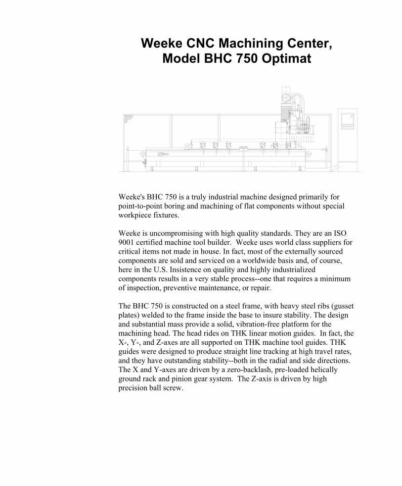
Weeke's BHC 750 is a truly industrial machine designed primarily for point-to-point boring and machining of flat components without special workpiece fixtures. Weeke is uncompromising with high quality standards. They are an ISO 9001 certified machine tool builder. Weeke uses world class suppliers for critical items not made in house. In fact, most of the externally sourced components are sold and serviced on a worldwide basis and, of course, here in the U.S. Insistence on quality and highly industrialized components results in a very stable process--one that requires a minimum of inspection, preventive maintenance, or repair. The BHC 750 is constructed on a steel frame, with heavy steel ribs (gusset plates) welded to the frame inside the base to insure stability. The design and substantial mass provide a solid, vibration-free platform for the machining head. The head rides on THK linear motion guides. In fact, the X-, Y-, and Z-axes are all supported on THK machine tool guides. THK guides were designed to produce straight line tracking at high travel rates, and they have outstanding stability--both in the radial and side directions. The X and Y-axes are driven by a zero-backlash, pre-loaded helically ground rack and pinion gear system. The Z-axis is driven by high precision ball screw.
Technical Specifications 21596-21601 January 18, 2001 Page 2
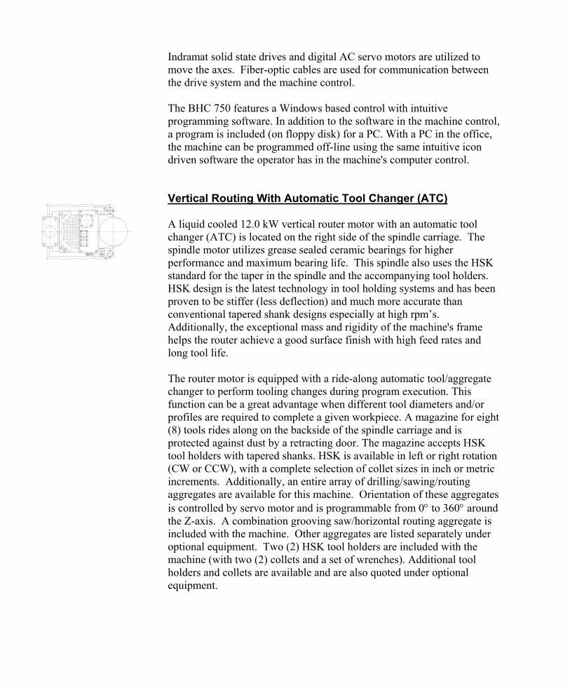
Indramat solid state drives and digital AC servo motors are utilized to move the axes. Fiber-optic cables are used for communication between the drive system and the machine control. The BHC 750 features a Windows based control with intuitive programming software. In addition to the software in the machine control, a program is included (on floppy disk) for a PC. With a PC in the office, the machine can be programmed off-line using the same intuitive icon driven software the operator has in the machine's computer control. Vertical Routing With Automatic Tool Changer (ATC) A liquid cooled 12.0 kW vertical router motor with an automatic tool changer (ATC) is located on the right side of the spindle carriage. The spindle motor utilizes grease sealed ceramic bearings for higher performance and maximum bearing life. This spindle also uses the HSK standard for the taper in the spindle and the accompanying tool holders. HSK design is the latest technology in tool holding systems and has been proven to be stiffer (less deflection) and much more accurate than conventional tapered shank designs especially at high rpm’s. Additionally, the exceptional mass and rigidity of the machine's frame helps the router achieve a good surface finish with high feed rates and long tool life. The router motor is equipped with a ride-along automatic tool/aggregate changer to perform tooling changes during program execution. This function can be a great advantage when different tool diameters and/or profiles are required to complete a given workpiece. A magazine for eight (8) tools rides along on the backside of the spindle carriage and is protected against dust by a retracting door. The magazine accepts HSK tool holders with tapered shanks. HSK is available in left or right rotation (CW or CCW), with a complete selection of collet sizes in inch or metric increments. Additionally, an entire array of drilling/sawing/routing aggregates are available for this machine. Orientation of these aggregates is controlled by servo motor and is programmable from 0 to 360 around the Z-axis. A combination grooving saw/horizontal routing aggregate is included with the machine. Other aggregates are listed separately under optional equipment. Two (2) HSK tool holders are included with the machine (with two (2) collets and a set of wrenches). Additional tool holders and collets are available and are also quoted under optional equipment.
Technical Specifications 21596-21601 January 18, 2001 Page 3
Frequency Inverter A solid state frequency inverter manufactured by KEB is utilized to power the router. The inverter output is programmable through the control with constant power from 9000 rpm to 18000 rpm. Spindle rotation, RH or LH, is also programmable. The inverter has a 21.0 KVA power rating. Auxiliary Vertical Router A liquid cooled 7.5 kW vertical router motor is located at the back of the spindle carriage. This spindle motor also utilizes grease sealed ceramic bearings for higher performance and maximum bearing life. It also uses the HSK standard for the taper in the spindle and the accompanying tool holders. This spindle can access and use the automatic tool changer (ATC) magazine, but is not capable of handling aggregates. One HSK63 toolholder and one ½-inch collet are supplied with this spindle. Vertical Boring with 22 Spindles The vertical-boring head is located on the right side of the spindle carriage and has twenty-two (22) spindles. Twelve (12) spindles aligned in the X-axis are typically utilized for row hole boring. Nine (9) spindles are also aligned in the Y-axis and are typically utilized for construction hole boring. These spindles are on 32-mm center distances. They utilize standard boring bits, 70 mm long, up to 20 mm in diameter, with 10-mm diameter smooth shanks. One (1) special spindle, for large drills up to 35-mm diameter, is offset from the in-line boring heads. A 1.5 kW motor drives the vertical-boring gearbox. Horizontal Boring with Six Individually Selectable Spindles The horizontal-boring block has two (2) spindles oriented to the right, and two (2) to the left (X-axis), on 32-mm centers. There are also two (2) drilling spindles in the Y-axis. One (1) spindle is oriented to the front, and one (1) spindle to the back of the machine. Note: maximum horizontal boring depth is 45 mm.
Technical Specifications 21596-21601 January 18, 2001 Page 4
Panel Support Benches – Console Style Eight (8) panel support benches have three (3) vacuum pods each. The support benches have a control button conveniently located on the front to disengage the pneumatic brakes for the X-axis adjustment of the bench. Two of the vacuum pods are 140 mm x 115 mm x 100 mm (height). The third vacuum pod is 75 mm x 125 mm x 100 mm (height). Metric scales are located on the machine for easy positioning of both the panel support benches and the vacuum pods along the benches. Panel Feeding Rails Panel feeding rails are attached to one side of each support bench (can be moved to either side). The rails move upward to provide a smooth surface for loading and unloading. The rails retract downward to set the panels on the vacuum pods. Part Positioning Stops There are two complete sets of positioning stops on the machine. One set is located at the back of the machine and is used for positioning large parts. A second set of stops is located at the front of the support benches and is used for positioning narrow parts. Either set of stops can be used for positioning left-hand or right-hand parts. Vacuum Pump A powerful vacuum pump with 100 M3/hr capacity has enough reserve suction for the most demanding jobs. Dust Extraction Efficiency Dust extraction efficiency is maximized by two central dust collection ports, each 250 mm in diameter, with individually controlled connections to the router, vertical boring block, and grooving saw. As each router, grooving saw, etc. is activated, dust ports to other devices are automatically closed. The dust brush cover for the main router spindle can be programmed in length in order to accommodate different lengths of router bits.
Technical Specifications 21596-21601 January 18, 2001 Page 5
Perimeter Fence A perimeter fence helps prevent accidental intrusion from the ends or back of the machine. Safety Mats Safety mats will assist in stopping the machine if the operator enters the working area while the machining head is in operation. The mats are divided into two (2) working zones so you may load or unload parts at one end of the machine while the machine continues to work on the opposite end. Weeke 2000-IPC The machine is equipped with the Weeke 2000-IPC continuous path control with intuitive programming software. The Weeke control features a graphic operator interface with icons to simplify operation. Programming with Windows based WoodWOP software is with simple coordinates or by the entry of formulas to define the relationship between panel size and hole locations (parametric programming). Some of the features of the Weeke 2000-IPC CNC control include the following:
Industrial Personal Computer (IPC) for operator interface
the IPC is a Windows based Pentium compatible machine
2.0 GB hard drive
64 MB of RAM
floppy disk drive 3.5"
the IPC is connected to a NUM programmable logic control for accurate and reliable control of all machine functions
high resolution color graphics (VGA) with 17" color monitor
full function industrial keyboard
bar code reader interface and software included (scanning device is optional)
simultaneous three-axis linear control
EtherNET interface for local area network (connection to office PCs)
fully compatible and integrated with Holzma Cut-Rite Plus software
report generation software included
post processor for DXF file conversion is included
RS-232 serial interface for simple PC connection
Technical Specifications 21596-21601 January 18, 2001 Page 6
Off-Line Programming In addition to the WoodWOP programming software in the machine control, this same software is included (on CD ROM) for a PC. Using a PC in the office, the machine can be programmed off-line with the same intuitive icon driven WoodWOP software that the operator has within the machine control. The PC software has no copy protection. If you have a network, you may install the software on as many PCs as you like without buying additional copies of the software. Off-Line Programming Training Two seats in the Stiles Education course BP050 for training in the WoodWOP software are included with the machine. This course is designed to provide Weeke point-to-point owners with the introductory information necessary to utilize WoodWOP software. Participants must have basic computer skills including use of Windows "operating systems". Stiles Education classes are conducted at Stiles Machinery locations. The customer is responsible for all travel and living expenses incurred during training. Training scholarships will expire one (1) year from machine delivery. To enroll your employees, please contact Stiles Education at (616) 698-7500. Number of vertical drilling spindles 22Vertical drilling spindle power 1.5 kWNumber of horizontal drilling spindles 6Horizontal drilling spindle power 1.5 kWATC router spindle power (power constant from 9000 rpm to 18000 rpm) 12.0 kWTool magazine capacity 8 toolsAuxiliary router motor 7.5 kWHSK63 tool holders supplied 3Collets for HSK63 tool holders 3Aggregate Combination grooving saw/
horizontal routing aggregateNumber of panel support benches 8Number of vacuum cups per bench/total 3/24Number of panel feeding rails 8Vacuum pump capacity 100 M3/hrLength of machine 7000 mmWidth of machine 4200 mmHeight of machine 2600 mm
Technical Specifications
Technical Specifications 21596-21601 January 18, 2001 Page 7
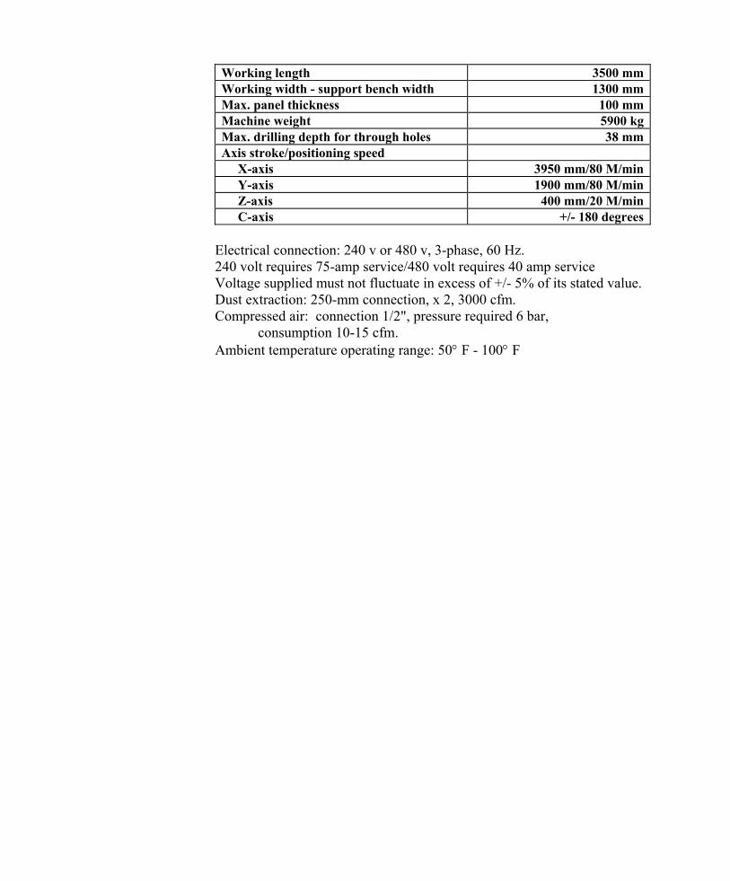
Working length 3500 mmWorking width - support bench width 1300 mmMax. panel thickness 100 mmMachine weight 5900 kgMax. drilling depth for through holes 38 mmAxis stroke/positioning speed X-axis 3950 mm/80 M/min Y-axis 1900 mm/80 M/min Z-axis 400 mm/20 M/min C-axis +/- 180 degrees
Electrical connection: 240 v or 480 v, 3-phase, 60 Hz. 240 volt requires 75-amp service/480 volt requires 40 amp service Voltage supplied must not fluctuate in excess of +/- 5% of its stated value. Dust extraction: 250-mm connection, x 2, 3000 cfm. Compressed air: connection 1/2", pressure required 6 bar, consumption 10-15 cfm. Ambient temperature operating range: 50 F - 100 F