Embed Size (px)
Citation preview

Weld-After-Backfill, A Growing Industry Practice Authors: Bob Buchanan1 - Canusa-CPS
Dennis Dechant2 - Northwest Pipe Company Ralph Warner3 - National Welding Corp.
Keywords: Steel Water Pipeline, Welding, Backfill, Corrosion Coatings Abstract This study documents a series of eight trials of the weld-after backfill (W-A-B) sequence. This sequence of pipeline construction was first used in the late 1980’s on a pipeline in Texas. Since then, more than 45 major pipeline projects in the United States have been constructed using W-A-B. These projects included a variety of pipe joint coating materials such as mortar diapers, concrete encasement, tape coatings and heat-shrinkable sleeves. This study focuses on heat-shrinkable sleeves for coating the pipe joint, prior to backfill. A growing practice in steel water pipeline construction entails fitting bell & spigot pipe segments together, installing field joint coatings and backfilling the pipe prior to welding. Welding is then completed from the inside of the pipe after the pipe has been backfilled. Weld-after-backfill has proven to be successful in minimizing the length of open trench, improving project safety and speeding up pipeline laying, resulting in design, economic and safety advantages over traditional steel water pipeline construction methods. These advantages benefit the owner, designer, contractors and suppliers. W-A-B is recommended for projects with lap welded joints, which is the predominant joint design for most water pipeline installations. The welding process, however, produces high temperatures on the pipe wall, which may damage some corrosion coatings. Research by Northwest Pipe, National Welding and Canusa-CPS was completed to evaluate various welding processes, measure temperatures and assess the affects of the W-A-B sequence on exterior field
1 Marketing Manager, Canusa-CPS, Toronto, Ontario 2 Chief Corporate Engineer, Northwest Pipe Company, Denver, Colorado 3 Operations Manager, National Welding Corporation, Salt Lake City, Utah
- 1 -

joint coatings. Various heat-shrinkable sleeve-coating systems were tested in order to optimize current practices. This paper describes the W-A-B sequence, explains typical installation and welding processes, provides data from the research and makes recommendations as to best practices when this construction method is used. Introduction Trials were held at the Northwest Pipe Company's Denver yard in partnership with Canusa-CPS and National Welding in March and July 2004 respectively. The observations and data are summarized in the figures and tables below. The objectives of the trial applications were threefold: 1. Measure and understand the amount of heat produced during the welding process. 2. Evaluate various corrosion protection systems and how the heat affected the
materials. 3. Demonstrate the effective implementation of W-A-B with the products and
welding processes used. Two different welding techniques were used and eight trials were designed to evaluate various system designs consisting of an optional underlay and a primary corrosion protection sleeve. The techniques and trials were meant to evaluate the effects of different welding processes and the high temperatures generated on the field joint corrosion protection materials. The corrosion protection system configuration variables included adhesive and backing component types, thicknesses and shrink recovery ratios used for the underlay and outer sleeve. The trials were done on thin 0.250” wall (6mm) bell & spigot pipe with cement mortar lining. Since the pipe used were "drop ends" or remnants from Northwest’s production yard some gaps in the bell & spigot were greater than field specs may have allowed. Backfill conditions were also not completely representative of the field and these variables are believed to have created a worst-case situation, which affected results of the tests. Pipe and Backfill Set Up Eight pipe joints were assembled, fitted with various heat-shrinkable sleeves, backfilled and welded in the course of these trials. Pairs of short pipe sections with bell ends were attached by a short plain end by plain end pipe section. Four pairs of these pipe assemblies were used during these trials. Each assembly was then placed in a ‘joint box’ designed to hold the pipe joints and backfill material, approximating trench conditions. The joint box allows the backfill to surround the pipe joints at a depth of least 12 inches all the way around the pipe. The backfill material was mortar sand from Northwest Pipe’s mortar coating and lining operations at the plant.
- 2 -

Welding Comments and Data Two welding processes were used during the trials; Shielded Metal Arc Welding (SMAW), commonly referred to as stick welding, and Flux Core Arc Welding (FCAW), or wire welding. Each process was used to complete a full fillet weld on the inside of the pipe joints in these trials. These two welding processes are the most common processes used in production pipeline field welding. SMAW involves the use of a rod or stick electrode that has a flux bonded to the outside surface. The flux forms the shield for the weld puddle to prevent oxygen impurities and inclusions during the welding process. FCAW involves the use of a hollow wire electrode with flux in the core in addition to a shielding inert gas to protect the weld puddle and prevent impurities and inclusions during the welding process. The two processes differ primarily in the deposition rate of metal applied to the joint. SMAW progress is made in either an uphill or downhill direction on the pipe joint, depending on the electrode, while FCAW progress is usually made in an uphill direction on the pipe joint. Observations of several welding parameters were made during the weld sequence on each pipe joint. Data gathered includes the electrical parameters of amperage (I), voltage (E) and travel speed (V), the rate at which the weld is applied to the joint. These three parameters were used to calculate reasonable levels of heat input, using the following equation1):
Sample Heat Input Data and Calculations:
Amperage 210 Voltage 26 Travel Speed (in/min) 9 Heat Input (Joules) (210 x 26 x 60) / 9 = 36,400
Other data included the use of a "temp stick" grid on each welded joint. A temp stick is a crayon used in the steel industry to determine the temperature of a metal surface. The temp stick is formulated to melt at a pre-determined temperature. The grid was created, using temp sticks with melting points between 800ºF (427ºC) and 200ºF (93ºC), in 100ºF (56ºC) increments. Starting at the top with an 800ºF stick, a line was drawn perpendicular to the joint to be welded. Two inches below that a line was drawn with a 700ºF stick, and so forth down the joint, finishing with a 200ºF line. After welding, the melt back distances were measured and recorded. The temp stick grid gives a qualitative indication of heat transfer through the steel adjacent to the weld bead. Specifically, the grid indicates the distance from the weld root at which
- 3 -

the metal temperature reached the temp stick melting point. This is a measure of heat transfer away from the weld. Some joints in the trials included two grids, one for each welding process as half of the joint was welded with SMAW and the other half with FCAW. In some instances the grid was impossible to measure due to the temp stick mark being blurred or obscured by welding smoke and soot or by smearing due to direct contact by the welder. Note that the welding produced a heat zone approximately 1.3" (35mm) wide with steel surface temperatures of at least 800ºF (427ºC) on the inside of the pipe. This was important to consider when analyzing the effects of the heat on the exterior coating. The data from Trial #2 is shown in Figure 1 below as a sample.
Trial #2 FCAW
-4.0 -3.0 -2.0 -1.0 0.0 1.0 2.0 3.0 4.0
200
300
400
500
600
700
800
(ºF)
Inches
Bell Side (d)
Spigot Side (d)
Figure 1: Temp Stick Melt Back Distance
- 4 -

Differences in Welding Processes It is assumed that both processes deposited approximately the same quantity of weld metal to complete the joint. The SMAW process required two passes to complete the weld on the pipe joints; a root pass and a fill pass. The heat input for the first pass using the SMAW process is generally low; in the 20,000 joules range. However the second pass is usually higher; in the 25,000 to 35,000 joules range. The FCAW process required one pass to complete the weld on a pipe joint. The heat input for the FCAW process was in the 27,000 to 40,000 joules range. The welding done in these trials was similar to that done under typical field conditions. Neither process used any special or non-standard methods. The electrical settings and welder techniques were the same as the welders use in the field. The joint assembly was also typical of field installed pipe joints. Coating Evaluation and Comments The various trials evaluated heat-shrinkable sleeves either as the only joint coating or combined with a protective underlay material. The variables were in the types of sleeves and underlay materials and in the design of these materials, i.e. backing and adhesive type and thickness. These variables are identified in Appendix B - Coating Performance. The welding temperatures had mixed effects between the trials but it was clear that both methods produced high temperatures below the field installed corrosion protection coating system. Figure 2 charts thermocouple readings taken below the joint coating as the welder passed the measurement point. These temperatures, as expected, resulted in varying effects on the coating.
T e m p e r a tu r e U n d e r S le e v eH e a t - A f f e c t e d A r e a
0
2 0 0
4 0 0
6 0 0
8 0 0
1 0 0 0
1 2 0 0
30 70 110
150
190 30 70 110
150
190
230
T im e
Hea
t-Affe
cted
Are
a Te
mp. F C A W 1
S M A W 1 - 1S M A W 1 - 2F C A W 2S M A W 2 - 1S M A W 2 - 2
Trial 2 Trial 1
Figure 2: Time-Temperature Chart
- 5 -
Corrosion Protection Performance High temperatures can affect adhesives in different ways depending on the composition of the adhesive. Essentially, heat can cause an adhesive to decompose with the components separating. This was evident in the destructive peel adhesion evaluation after welding, as the adhesive that was exposed to high temperatures in some of the tests appeared soft and sticky while in others the adhesive appeared brittle. These two phenomenon occur because adhesives are not naturally homogenous so the soft components, like oils, plasticizers, etc., can separate out and be tacky while leaving the dryer components such as carbon black, pigments, fillers, etc. appear brittle. In simple terms, the heat "carbonized" the adhesive in the narrow heat-affected area zone directly over the weld. Additionally, during this process, low molecular weight volatile fractions within an adhesive, primarily asphalt based raw materials, will diffuse or "offgas", exerting vapor pressure under the backing material. Ultimately, all of these actions affect the adhesive's performance. To varying degrees, the heat also affected the heat-shrinkable sleeve backing to the point where some degradation of mechanical properties occurred as noted visibly by a fine line or crease which formed in the backing either intermittently or consistently around the pipe. This crease was a result of the backing being heated, stressed due to the vapor pressure mentioned above, and relaxed while under a confined load (backfill). Although this degradation may not be detected immediately as a holiday, it could develop a discontinuity over time due to pipe and soil movement applying pressure to the damaged area. Trials & Observations - Effects on the Corrosion Protection Systems Relative to the corrosion protection systems, a number of general observations may be made based on all of the trials. These, combined with specific data and observations from each of the trials, may be used to determine best practices. Appendix B identifies each of the trials with the configuration of the systems noted along with general observations. General Comments 1. Adhesives have a propensity to melt, flow and offgas under high heat. For some
of the test products, this caused adhesive flow below the polyethylene backing into the weld area resulting in minor burning of the adhesive.
2. Butyl-based adhesives have lower flow characteristics and less propensity to offgas than adhesives with higher levels of asphalt content and, thus, were not affected as dramatically.
3. When an adhesive offgasses, vapor pressure is exerted under the backing and the heated backing will try to expand then contract as it cools. This creates greater stress on the backing, which is exhibited by the creasing noted.
- 6 -

4. Polyethylene backings in a single layer system may be affected by heat and as noted above such that some degradation in mechanical properties may occur. These effects are dependent upon pipe wall thickness.
5. Gaps in the bell & spigot allow heat flow-through to occur which can adversely affect the sleeve at the step down from the bell end to the spigot. Establishing joint tolerances as specified in AWWA2) C-200 and AWWA C-206 can prevent this.
6. It is important to remember that the performance of a heat-shrinkable sleeve system is dependent upon the combination of the backing and the adhesive over the entire width of the sleeve. Discontinuities in the adhesive over a small area near the weld zone should not adversely affect the overall performance of the sleeve.
7. To put the effects of heat into perspective, the high temperature zone or heat affected area is approximately 1" (2.5cm) wide. A calculation of total sleeve coverage area versus the affected area for a 48" (122cm) diameter pipe an 18" (45cm) wide sleeve is:
Sleeve area = 45 x 122 x π = 17240 cm2 Weld affected zone = 2.54 x 122 x π = 975 cm2 or 5.6% of the total protected area
System Performance Conclusions Much of the data gathered could be considered empirical in nature, nevertheless, based on the results of the coatings performance, it is apparent that both welding processes produce sufficiently high enough temperatures in the metal opposite the weld and under the coatings to have some affect on the coatings. Performance of the corrosion protection system is then a result of an adhesive's resistance to flow and offgas during welding and the resistance of a backing to expand and contract (expansion due to adhesive offgassing), and still maintain a seal against moisture. The reason that some systems perform better than others is that adhesives with higher molecular weight fractions have a lower propensity to offgas and flow, plus thicker backings have more resistance to expansion & contraction during the short heating and cooling cycle caused by welding. These trials were intentionally done using thin wall pipe to create a worst-case situation. Field trials on heavier wall pipe have shown better results for the coatings with used in the W-A-B sequence. All of the above said, it is believed that with appropriate products, proper installation, and experienced pipeline welders, the W-A-B process can produce sound pipeline projects and the performance of the joint coatings is not adversely affected.
- 7 -
Safety Considerations The W-A-B sequence is recommended as a project safety improvement for welded pipeline projects for a number of reasons. Primarily however, by fitting pipe segments together, installing field joint coatings and backfilling the pipe prior to welding, internal bracing in large diameter pipelines may be removed prior to any work being performed inside the pipeline. This work would include welding, inspection and interior lining operations and the removal of bracing greatly reduces the risks of working inside a pipeline. Pipelines are usually considered a confined space under OSHA guidelines and pipelines of 72" (1.8m) diameter and less present particular entrapment hazards when workers are required to work through bracing, making rapid rescue or evacuation nearly impossible. Pipelines large than 72" (1.8m) diameter that utilize extensive bracing also present similar hazards. Refer to OSHA3) - 29CFR 1910.146 App F (B) 10. “3) Portal size.
(a) Restricted -- A portal of 24 inches or less in the least dimension. Portals of this size are too small to allow a rescuer to simply enter the space while using SCBA. The portal size is also too small to allow normal spinal immobilization of an injured employee.” SCBA is Self Contained Breathing Apparatus
Additionally, W-A-B results in less open trench time during pipeline installation. This lowers the risks associated with open trenches in urban and residential areas. Designers should give consideration to confined space conditions, constructability and the comparative risks as well as other benefits of W-A-B when creating specifications for their projects. Constructability Considerations For pipelines that are designed for a single lap weld, the installation and welding can be on parallel production paths as opposed to being in series, taking the welding out of the installation critical path. This also allows the pipeline to reach ground temperature prior to welding. Thermal stresses can be avoided and expansion joints can be eliminated. The W-A-B sequence allows the backfill and welding to share front ends with a few joints of welded pipe exposed to thermal stresses at any time. The backfill is more consistent through the course of the pipeline installation, because the backfill operations are not interrupted by expansion joints.
- 8 -
Recommendations Recently, at AWWA SWPMTAC4) technical committee meetings, the W-A-B process was discussed at length. The conclusion was that advisory language was to be put into relevant standards as noted in Appendix A. This must be considered when engineering any water pipeline project. Relative to specifications, make recommendations for use of a proven system, possibly with protective underlay materials, and particularly for thin wall pipe, tight joint gap tolerances that meet AWWA standards. Attention to welding processes by monitoring and controlling heat input at the pipe joint is also desirable. References 1) Procedure Handbook of Arc Welding - Lincoln Electric, Cleveland Ohio 2) AWWA - American Waterworks Association, Denver Colorado 3) OSHA - Occupational Safety and Health Administration, Washington, DC 4) SWPMTAC - Steel Water Pipe Manufacturers Technical Advisory Committee Acknowledgments The authors wish to thank Mr. Bill Fields of the Northwest Pipe Company, Denver for preparing the pipe samples and set up for these trials.
- 9 -

Appendix A - Welding Data
Heat Input Calculations
Welding Process
Number of Passes Voltage Amperage
Travel Speed (in./min.)
Heat Input (Joules)
Trial 1 FCAW 1 26 200 8.6 36,279 SMAW 2 28 110 6.7 27,582
Trial 2 FCAW 1 24 180 8.9 29,124 SMAW 2 29 110 7.5 25,520
Trial 3 FCAW 1 22 200 10.0 26,400 SMAW 2 30 150 7.1 38,298
Trial 4 FCAW 1 20 180 9.2 23,478 SMAW 2 30 150 7.0 38,571
Trial 5 FCAW 1 24 220 7.9 39,950 SMAW 2 27 140 6.5 34,892
Trial 6 FCAW 1 24 190 8.4 32,727 SMAW 2 27 140 5.7 39,789
Trial 7 FCAW 1 23 190 9.3 28,285 SMAW 2 26 130 6.8 29,824
Trial 8 FCAW 1 23 190 9.3 28,285 SMAW 2 27 140 5.2 43,448
Note: All SMAW heat inputs are calculated for the second pass, since that pass is a weave weld wherein the majority of the weld metal is deposited. Sample Temp Stick Melt Back Data
Melt Back Distance From Weld Root (inches) Trial 1
(FCAW) Trial 2
(FCAW) Trial 3
(FCAW) Trial 4
(SMAW) Trial 5
(SMAW) Trial 6
(SMAW) Temp Stick Melt Point (ºF) Spigot Bell Spigot Bell Spigot Bell Spigot Bell Spigot Bell Spigot Bell
200 -3.0 2.8 -2.8 2.9 -2.5 2.5 -2.0 2.4 -3.6 3.9 -4.5 3.8 300 -2.5 2.1 -2.1 2.5 -1.5 1.8 -1.9 2.1 -2.8 2.5 -3.3 2.9 400 -1.5 1.4 -1.6 2.4 -1.3 1.2 -1.4 1.8 -1.8 1.8 -2.8 2.3 500 -1.2 1.0 -1.3 1.5 -0.9 1.0 -1.0 1.3 -1.5 1.5 -1.8 1.9 600 -1.0 0.8 -0.7 1.4 -0.6 0.9 -0.9 1.1 -1.1 1.4 -1.5 1.6 700 -0.6 0.6 -0.6 1.3 -0.5 0.9 -0.6 1.1 -0.8 1.0 -1.1 1.0 800 -0.5 - -0.4 1.0 -0.4 0.6 -0.5 0.6 -0.5 0.8 -0.5 0.6
Notes: Temp stick data from was not gathered for both welding processes on all joints. This is due to changes made during the trials and to temp stick marks getting obliterated during the welding process. Three samples from each welding process are shown above.
- 10 -
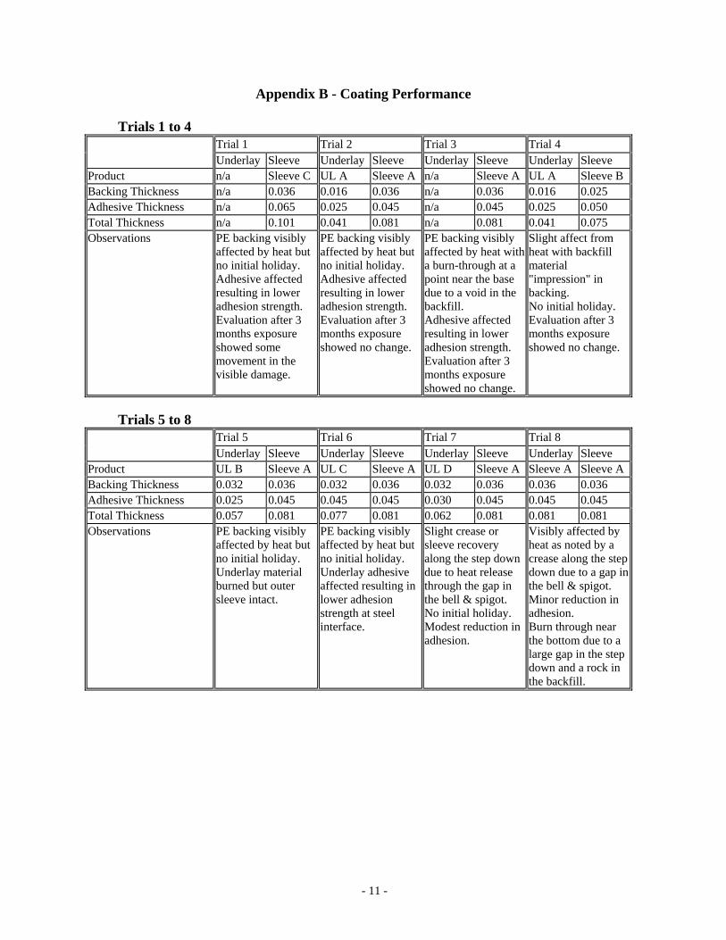
Appendix B - Coating Performance Trials 1 to 4
Trial 1 Trial 2 Trial 3 Trial 4 Underlay Sleeve Underlay Sleeve Underlay Sleeve Underlay Sleeve
Product n/a Sleeve C UL A Sleeve A n/a Sleeve A UL A Sleeve B Backing Thickness n/a 0.036 0.016 0.036 n/a 0.036 0.016 0.025 Adhesive Thickness n/a 0.065 0.025 0.045 n/a 0.045 0.025 0.050 Total Thickness n/a 0.101 0.041 0.081 n/a 0.081 0.041 0.075 Observations PE backing visibly
affected by heat but no initial holiday. Adhesive affected resulting in lower adhesion strength. Evaluation after 3 months exposure showed some movement in the visible damage.
PE backing visibly affected by heat but no initial holiday. Adhesive affected resulting in lower adhesion strength. Evaluation after 3 months exposure showed no change.
PE backing visibly affected by heat with a burn-through at a point near the base due to a void in the backfill. Adhesive affected resulting in lower adhesion strength. Evaluation after 3 months exposure showed no change.
Slight affect from heat with backfill material "impression" in backing. No initial holiday. Evaluation after 3 months exposure showed no change.
Trials 5 to 8
Trial 5 Trial 6 Trial 7 Trial 8 Underlay Sleeve Underlay Sleeve Underlay Sleeve Underlay Sleeve
Product UL B Sleeve A UL C Sleeve A UL D Sleeve A Sleeve A Sleeve ABacking Thickness 0.032 0.036 0.032 0.036 0.032 0.036 0.036 0.036 Adhesive Thickness 0.025 0.045 0.045 0.045 0.030 0.045 0.045 0.045 Total Thickness 0.057 0.081 0.077 0.081 0.062 0.081 0.081 0.081 Observations PE backing visibly
affected by heat but no initial holiday. Underlay material burned but outer sleeve intact.
PE backing visibly affected by heat but no initial holiday. Underlay adhesive affected resulting in lower adhesion strength at steel interface.
Slight crease or sleeve recovery along the step down due to heat release through the gap in the bell & spigot. No initial holiday. Modest reduction in adhesion.
Visibly affected by heat as noted by a crease along the step down due to a gap in the bell & spigot. Minor reduction in adhesion. Burn through near the bottom due to a large gap in the step down and a rock in the backfill.
- 11 -
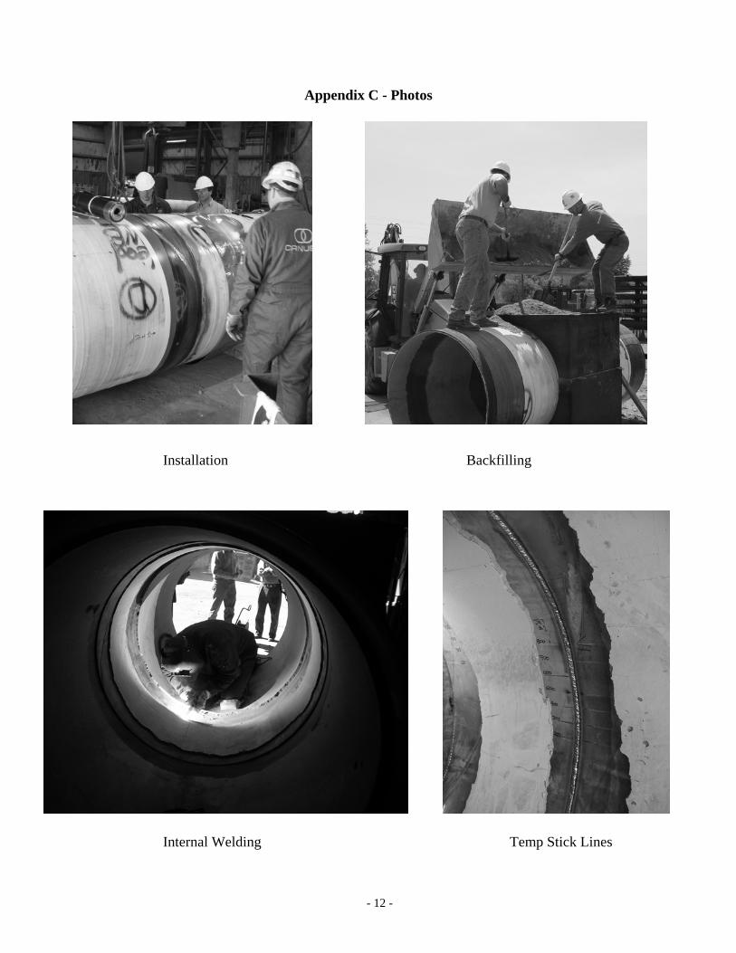
Appendix C - Photos
Installation Backfilling
Internal Welding Temp Stick Lines
- 12 -

Appendix C - Photos Continued
Typical Result after Welding
- 13 -

Appendix D - AWWA C216 Proposed W-A-B Text 4.3.3.4 Weld-After-Backfill Sequence. When the Weld-After-Backfill sequence is used, coating integrity results may differ due to variables in pipe wall thickness, backfill material, backfill compaction, moisture content and welding procedures. The purchaser should consult with the manufacturer(s) regarding recommended heat-shrinkable sleeves and additional coating products that may be required. In some instances use of historical data and/or field trials using the conditions specified for the project to demonstrate integrity of the recommended coating system is advised.
- 14 -