Embed Size (px)
DESCRIPTION
WELDING POSITIONSProduction Welding PositionsGroove Welds Fillet WeldsStandard Test PositionsPositions 1G, 3G, 6G, 2F, 5F, etc. are specially defined standard positions used for testing. They are properly referred to as Test Positions. Similar positions are found in ISO 6947 identified as PA, PC, PG, etc.Standard Testing PositionsTest positions are discreetly defined positions of test coupons that are used when mostly when testing welders. These positions have tolerance of ±15° from
Citation preview
WELDING POSITIONS
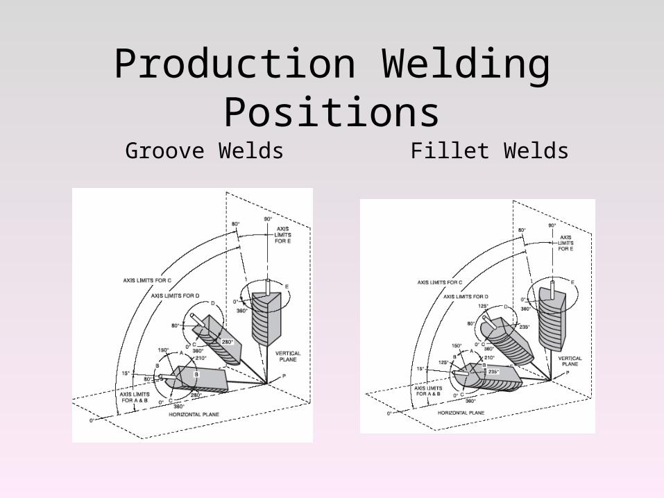
Production Welding Positions
Groove Welds Fillet Welds
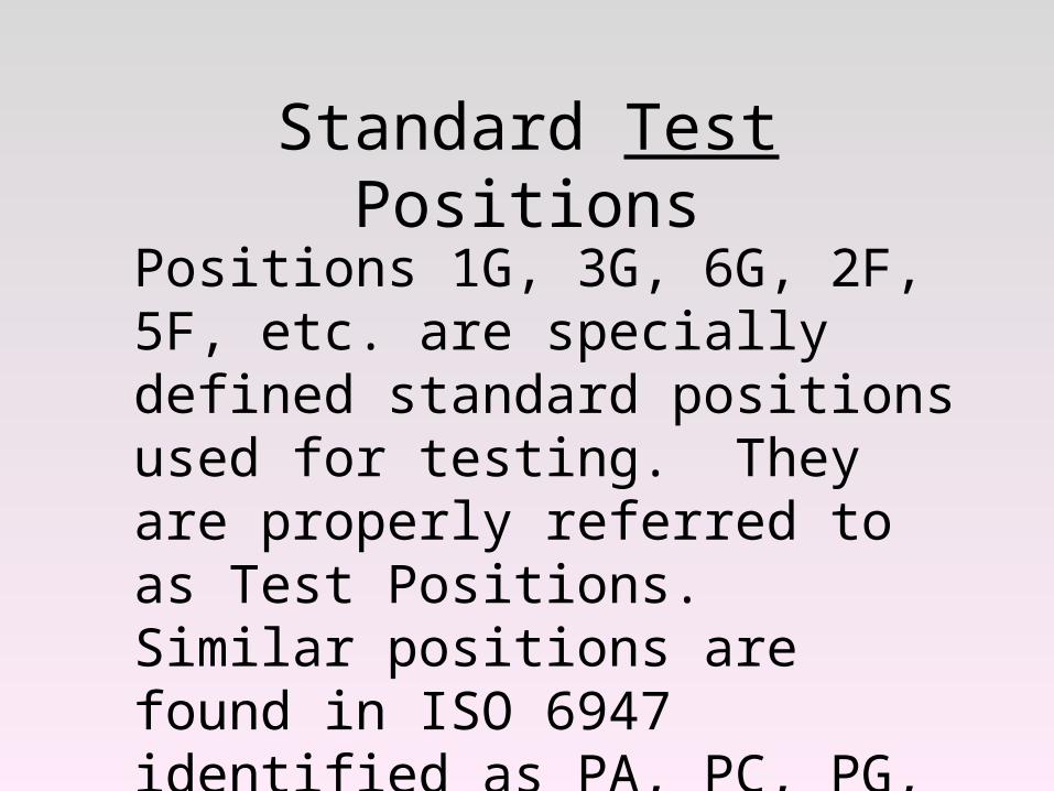
Standard Test Positions
Positions 1G, 3G, 6G, 2F, 5F, etc. are specially defined standard positions used for testing. They are properly referred to as Test Positions. Similar positions are found in ISO 6947 identified as PA, PC, PG, etc.
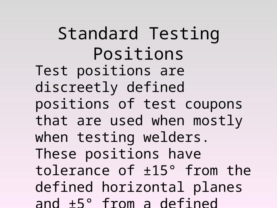
Standard Testing Positions
Test positions are discreetly defined positions of test coupons that are used when mostly when testing welders. These positions have tolerance of ±15° from the defined horizontal planes and ±5° from a defined vertical or inclined plane. See QW-120
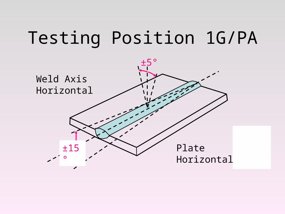
Testing Position 1G/PA
±15°
Weld Axis Horizontal
Plate Horizontal
±5°
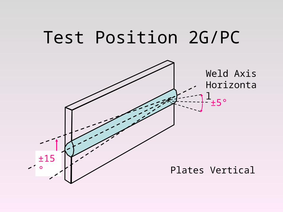
Test Position 2G/PC
Plates Vertical
Weld Axis Horizontal
±15°
±5°
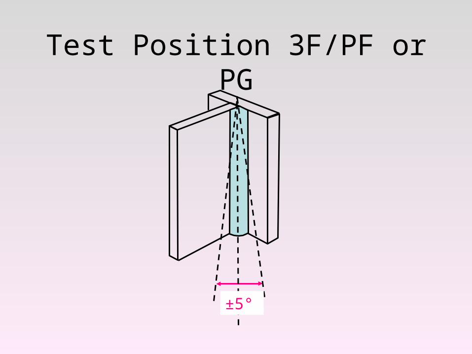
Test Position 3F/PF or PG
±5°
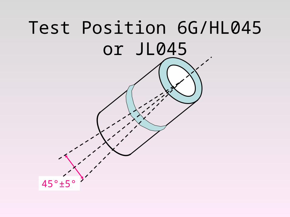
Test Position 6G/HL045 or JL045
45°±5°
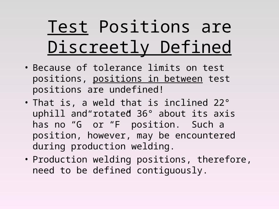
Test Positions are Discreetly Defined
• Because of tolerance limits on test positions, positions in between test positions are undefined!
• That is, a weld that is inclined 22° uphill and rotated 36° about its axis has no “G” or “F” position. Such a position, however, may be encountered during production welding.
• Production welding positions, therefore, need to be defined contiguously.
Test Positions Qualify Welders for Specific Welding Positions
Test Positions Welding Positions
Translations from test positions to welding positions are made in the construction codes. QW-461.9 is typical.
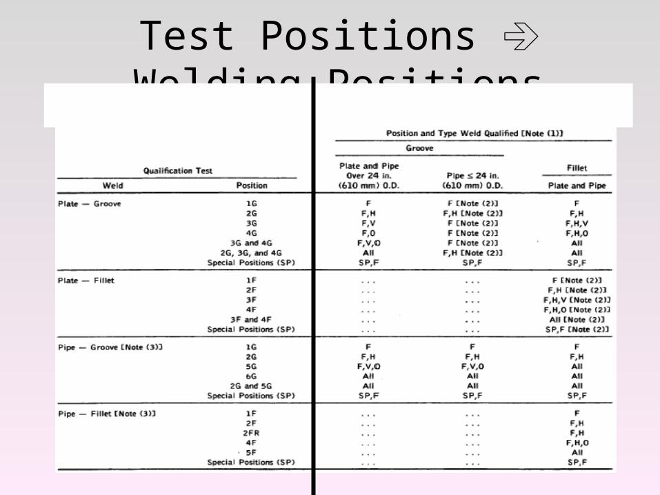
Test Positions Welding Positions
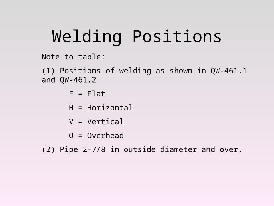
Welding PositionsNote to table:
(1) Positions of welding as shown in QW-461.1 and QW-461.2
F = Flat
H = Horizontal
V = Vertical
O = Overhead
(2) Pipe 2-7/8 in outside diameter and over.
Welding positions for groove welds are defined by the
following diagram.
NOTEWelding Position Diagrams are
contiguous.
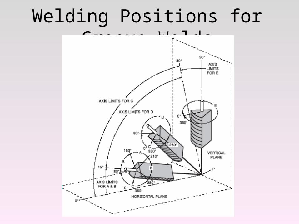
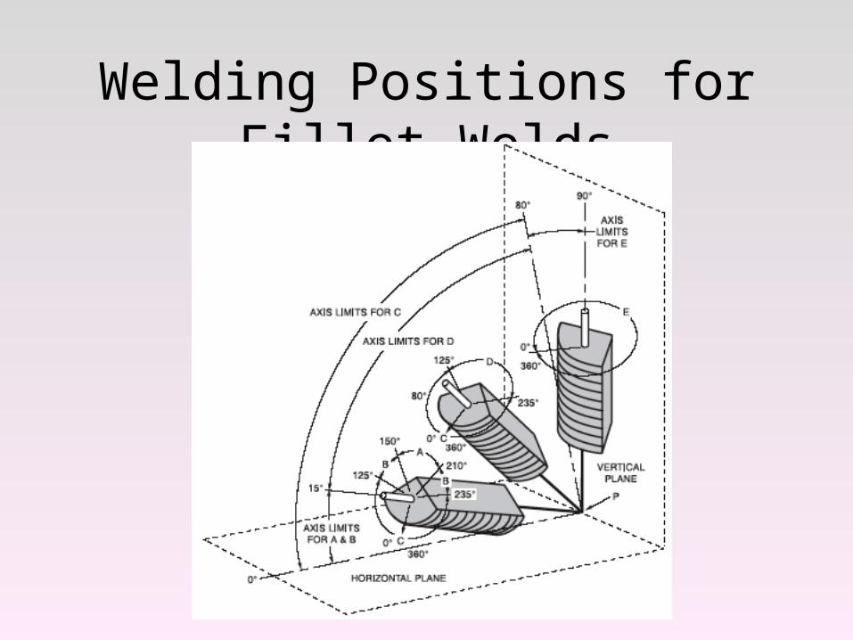
Welding Positions for Groove Welds
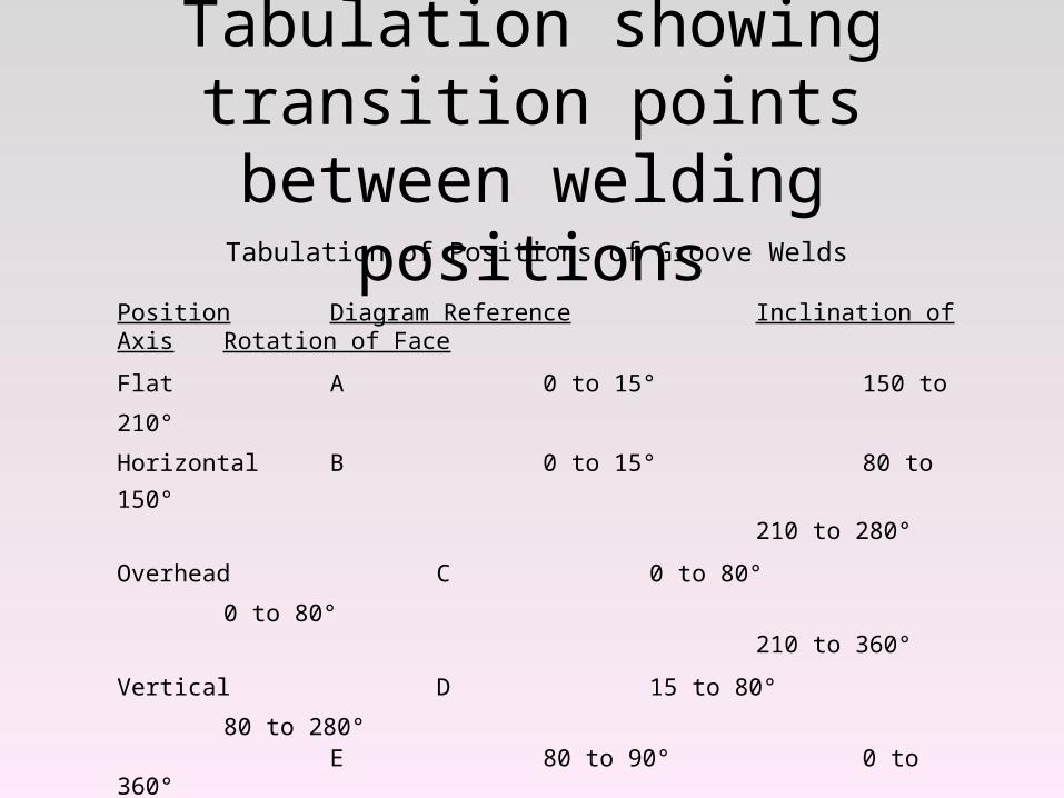
Tabulation showing transition points between welding positions
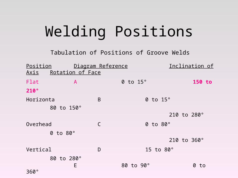
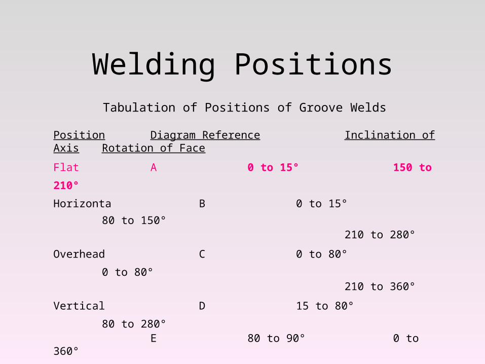
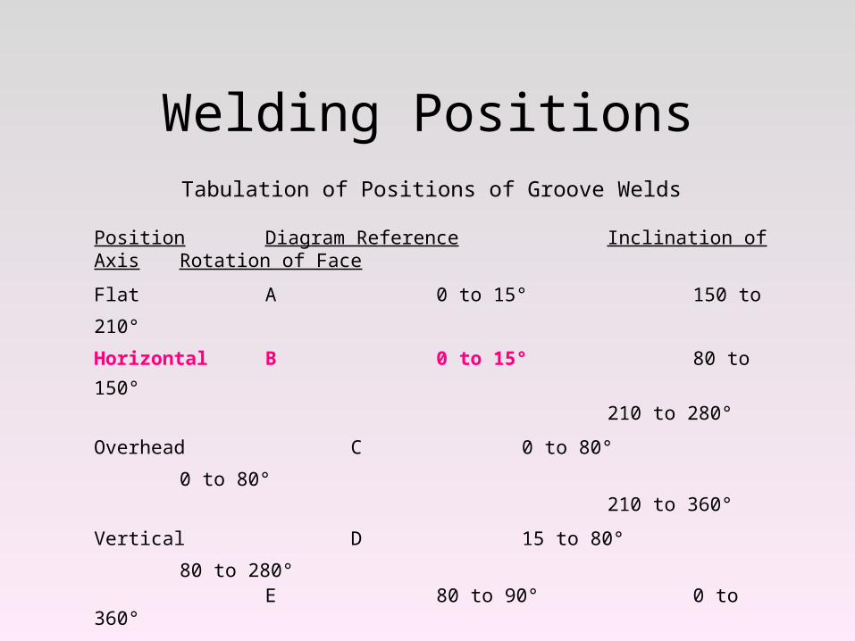
Tabulation of Positions of Groove Welds
Position Diagram Reference Inclination of Axis Rotation of Face
Flat A 0 to 15° 150 to 210°
Horizontal B 0 to 15° 80 to 150°210 to 280°
Overhead C 0 to 80° 0 to 80°210 to 360°
Vertical D 15 to 80° 80 to 280°E 80 to 90° 0 to 360°
How this table and the diagram on the previous page work are shown in the following diagrams

Flat Position
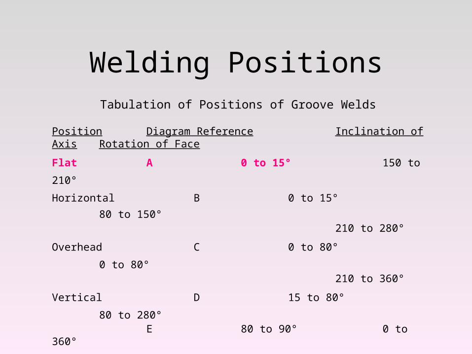
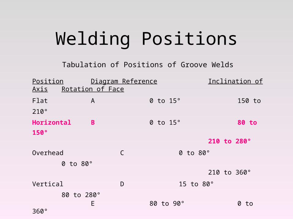
Welding PositionsTabulation of Positions of Groove Welds
Position Diagram Reference Inclination of Axis Rotation of Face
Flat A 0 to 15° 150 to 210°
Horizontal B 0 to 15° 80 to
150°210 to 280°
Overhead C 0 to 80° 0 to 80°210 to 360°
Vertical D 15 to 80° 80 to 280°E 80 to 90° 0 to 360°
How this table and the diagram on the previous page work are shown in the following diagrams
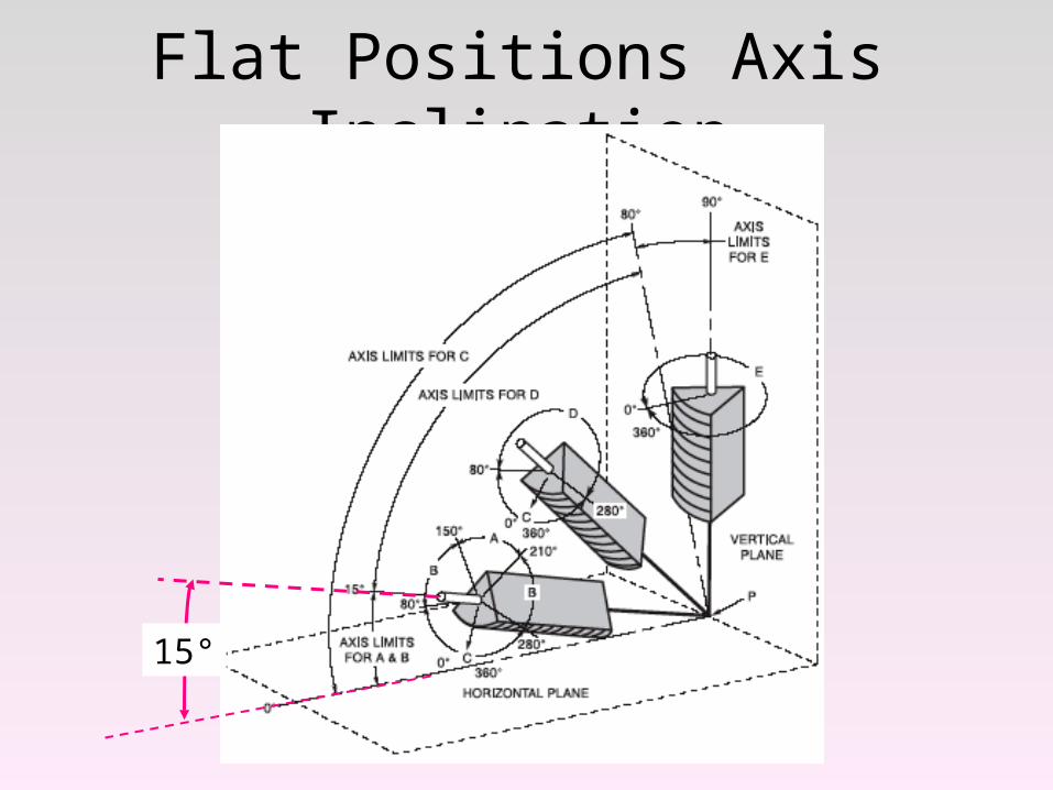
Flat Positions Axis Inclination
15°
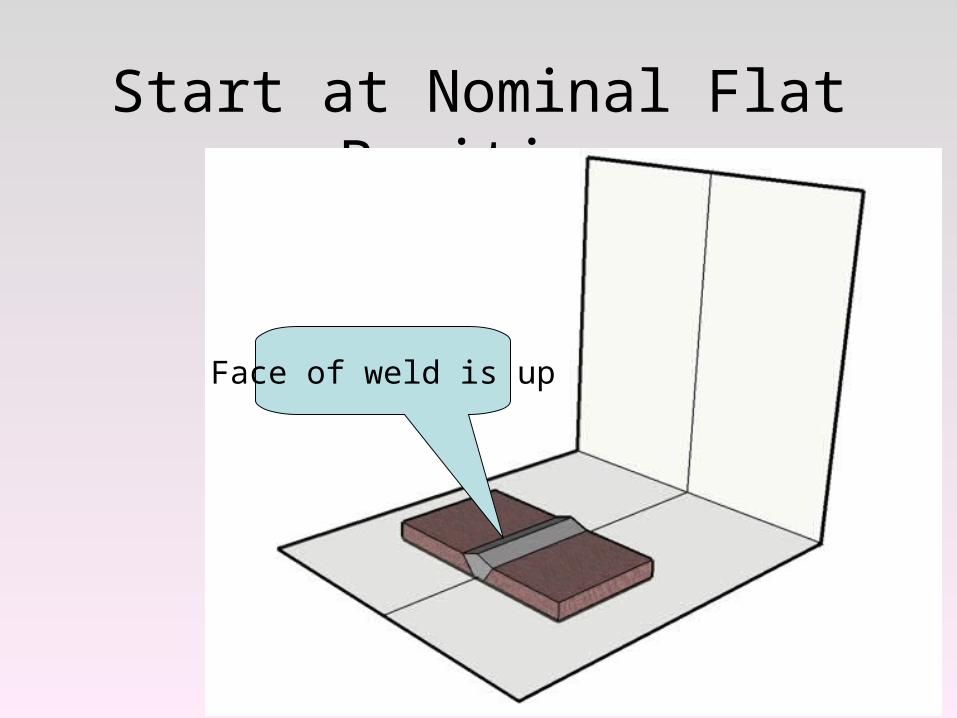
Start at Nominal Flat Position
Face of weld is up
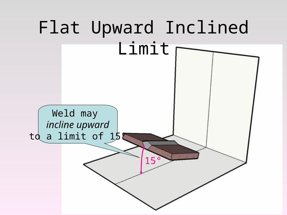
Flat Upward Inclined Limit
15°
Weld may incline upwardto a limit of 15°
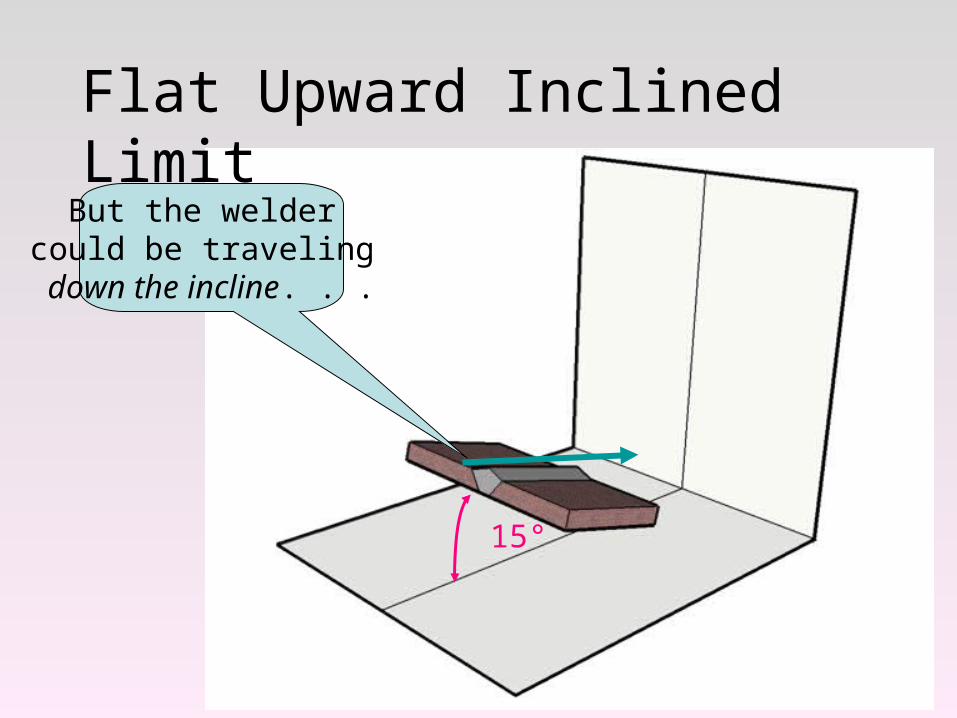
Flat Upward Inclined Limit
15°
But the welder could be traveling down the incline. . .
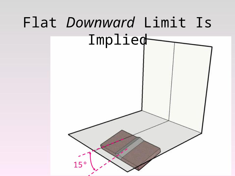
Flat Downward Limit Is Implied
15°
Welding PositionsTabulation of Positions of Groove Welds
Position Diagram Reference Inclination of Axis Rotation of Face
Flat A 0 to 15° 150 to 210°
Horizonta B 0 to 15° 80 to 150°210 to 280°
Overhead C 0 to 80° 0 to 80°210 to 360°
Vertical D 15 to 80° 80 to 280°E 80 to 90° 0 to 360°
How this table and the diagram on the previous page work are shown in the following diagrams
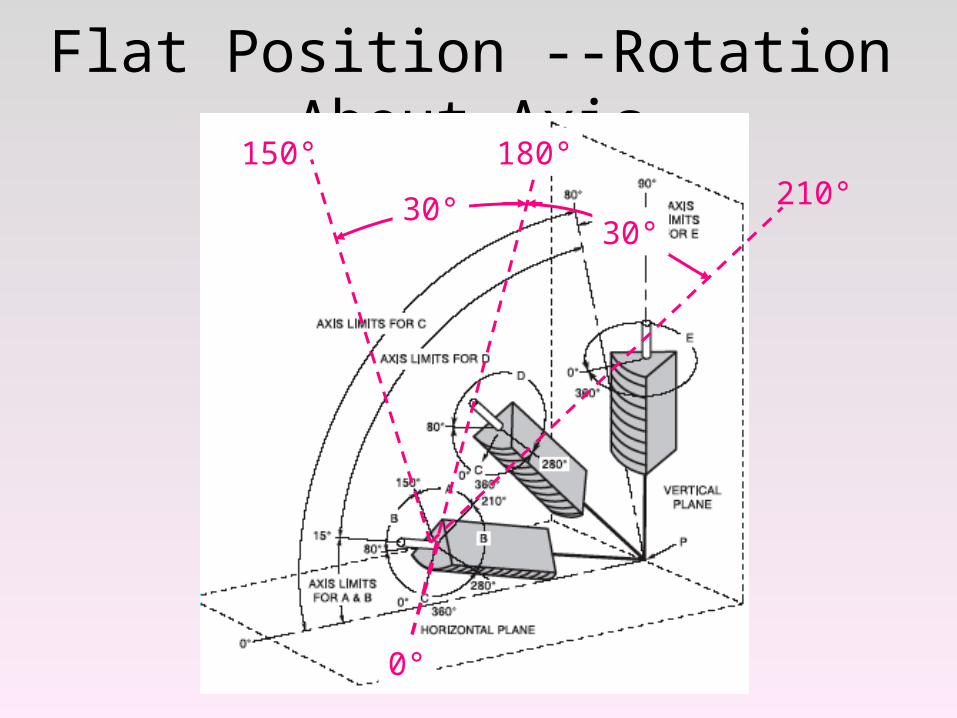
Flat Position --Rotation About Axis180°
0°
30°30°
150°210°
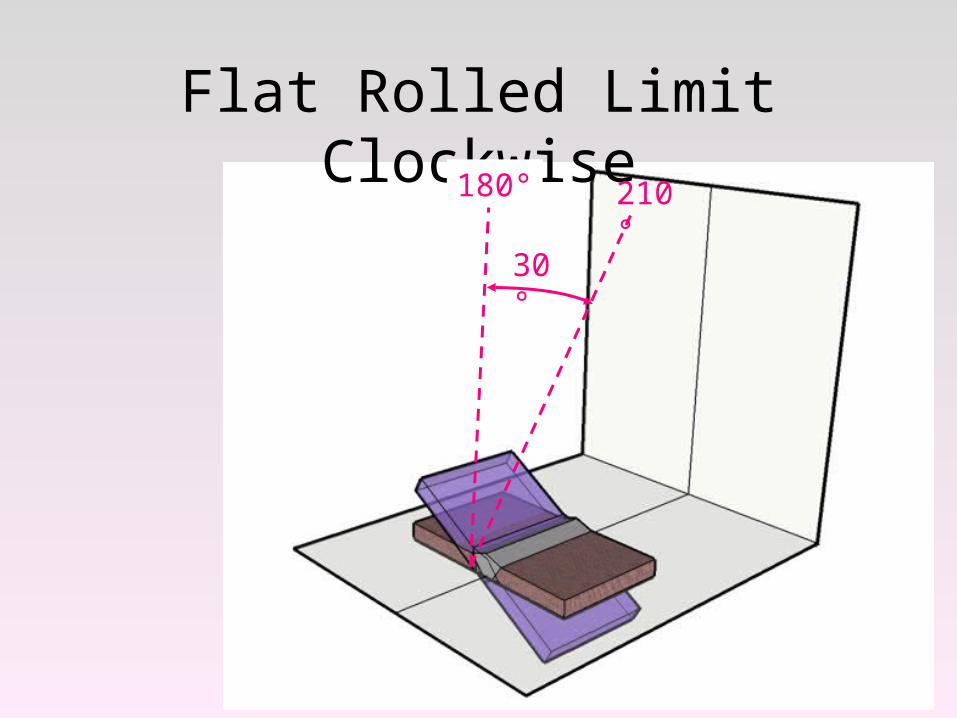
Flat Rolled Limit Clockwise210°180°
30°
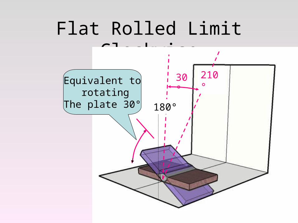
Flat Rolled Limit Clockwise
210°
180°
30°Equivalent to rotating
The plate 30°
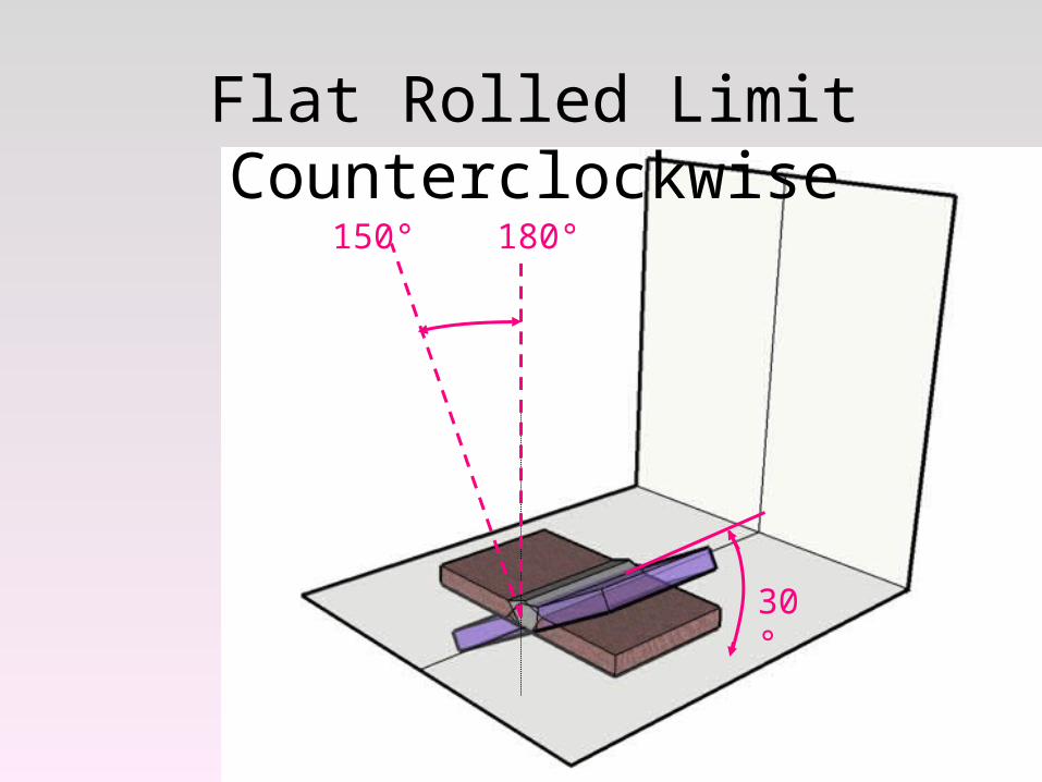
Flat Rolled Limit Counterclockwise
30°
150° 180°
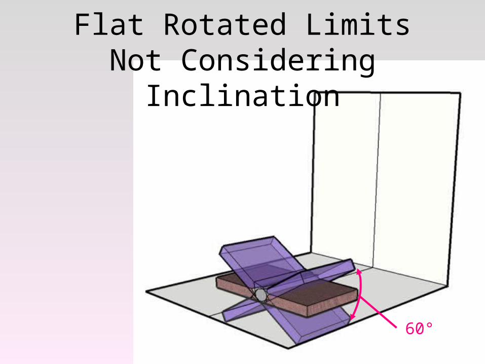
Flat Rotated Limits Not Considering Inclination
60°
Welding PositionsTabulation of Positions of Groove Welds
Position Diagram Reference Inclination of Axis Rotation of Face
Flat A 0 to 15° 150 to 210°
Horizonta B 0 to 15° 80 to 150°210 to 280°
Overhead C 0 to 80° 0 to 80°210 to 360°
Vertical D 15 to 80° 80 to 280°E 80 to 90° 0 to 360°
How this table and the diagram on the previous page work are shown in the following diagrams
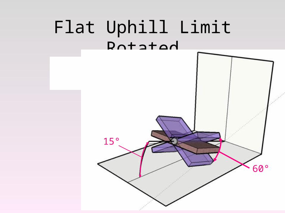
Flat Uphill Limit Rotated
15°
60°
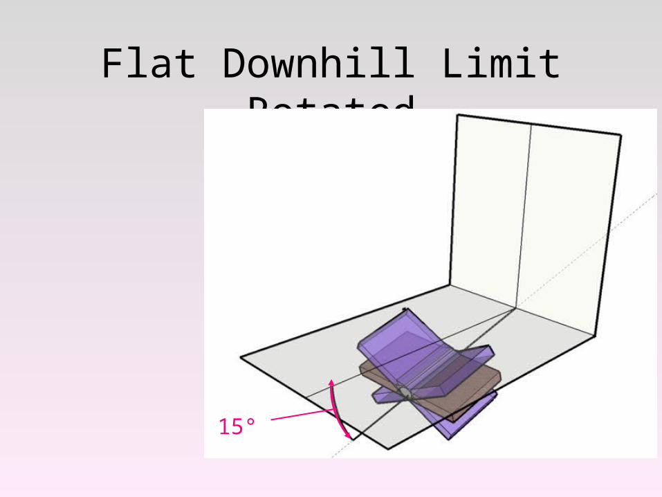
Flat Downhill Limit Rotated
15°
Welding PositionsTabulation of Positions of Groove Welds
Position Diagram Reference Inclination of Axis Rotation of Face
Flat A 0 to 15° 150 to 210°
Horizontal B 0 to 15° 80 to 150°210 to 280°
Overhead C 0 to 80° 0 to 80°210 to 360°
Vertical D 15 to 80° 80 to 280°E 80 to 90° 0 to 360°
How this table and the diagram on the previous page work are shown in the following diagrams
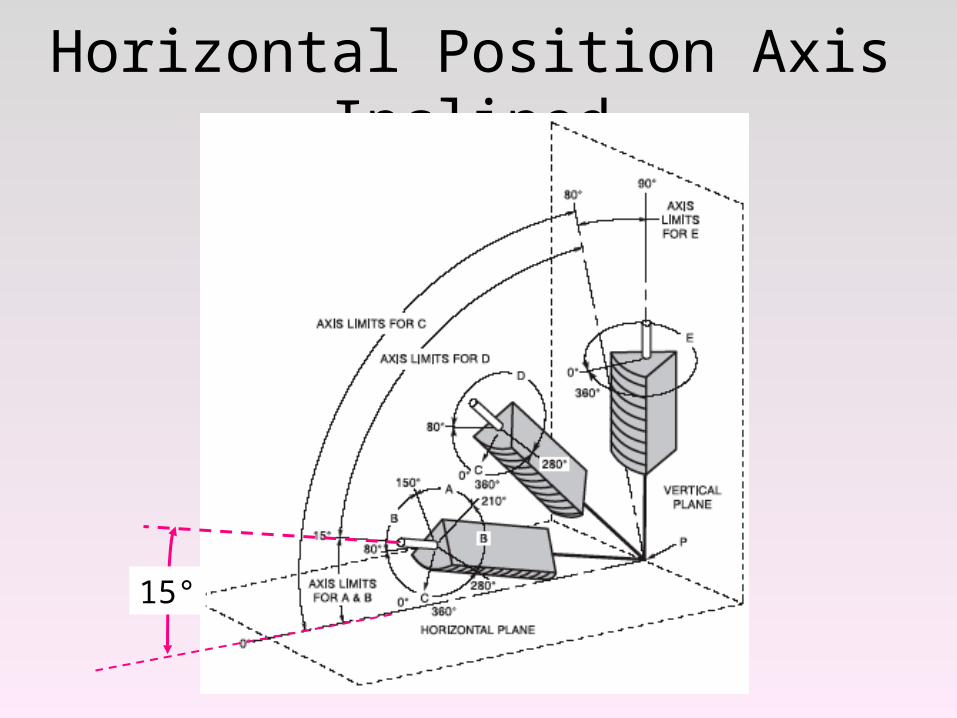
Horizontal Position Axis Inclined
15°
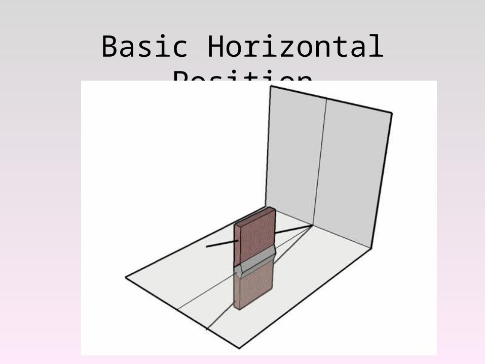
Basic Horizontal Position
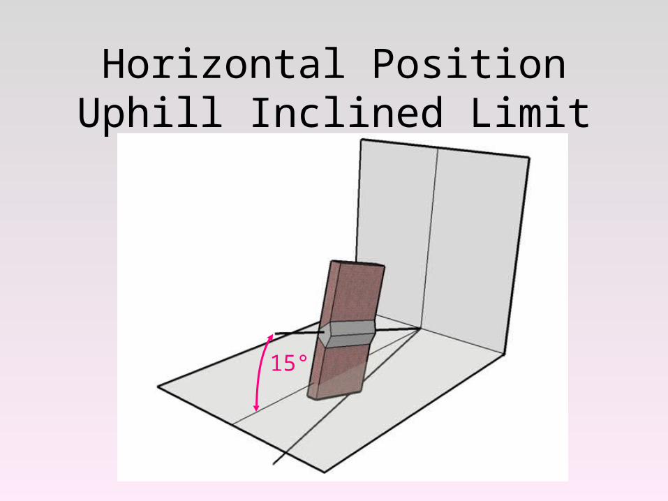
Horizontal Position Uphill Inclined Limit
15°
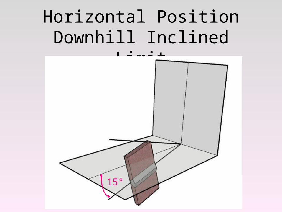
Horizontal Position Downhill Inclined Limit
15°
Welding PositionsTabulation of Positions of Groove Welds
Position Diagram Reference Inclination of Axis Rotation of Face
Flat A 0 to 15° 150 to 210°
Horizontal B 0 to 15° 80 to 150°210 to 280°
Overhead C 0 to 80° 0 to 80°210 to 360°
Vertical D 15 to 80° 80 to 280°E 80 to 90° 0 to 360°
How this table and the diagram on the previous page work are shown in the following diagrams
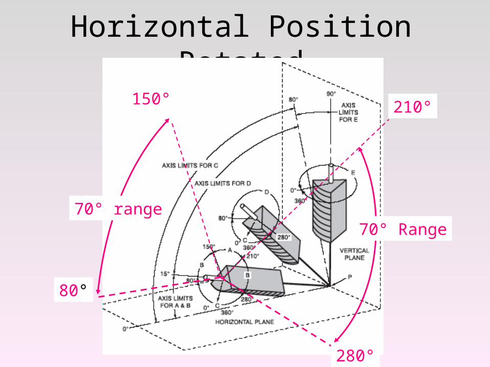
Horizontal Position Rotated
80°
150°
70° range
210°
280°
70° Range
210°
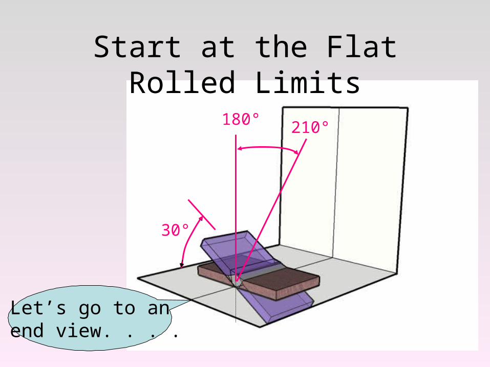
Start at the Flat Rolled Limits
180°
30°
Let’s go to an end view. . . .
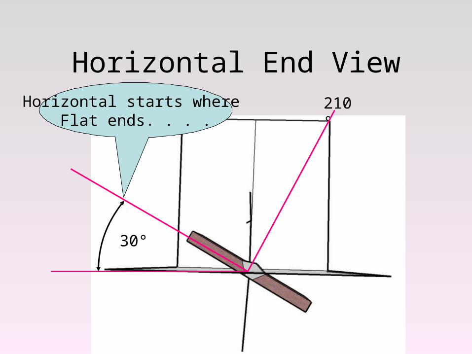
Horizontal End View
30°
Horizontal starts where Flat ends. . . .
210°
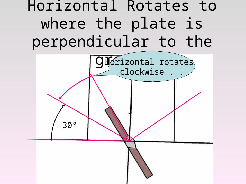
Horizontal Rotates to where the plate is perpendicular to the ground
30°
Horizontal rotates clockwise . .
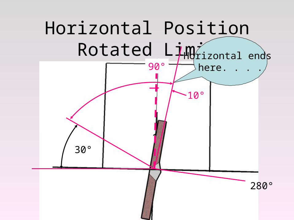
Horizontal Position Rotated Limit
30°
Horizontal ends here. . . .
10°
90°
280°
70°
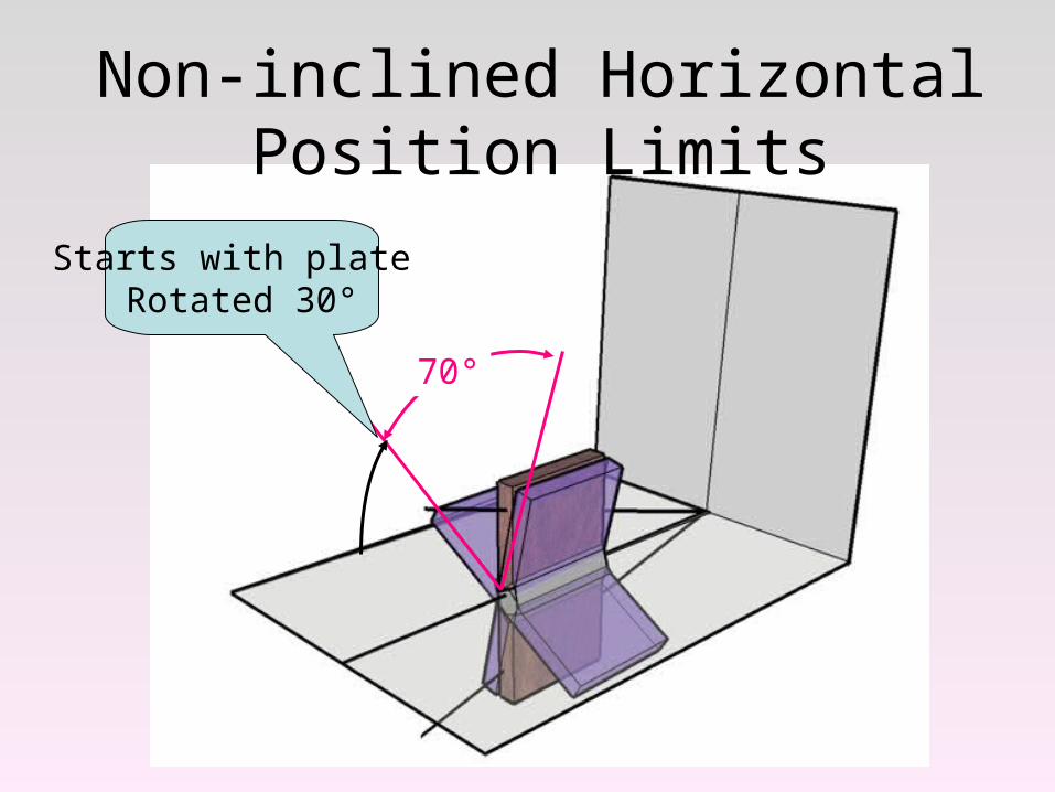
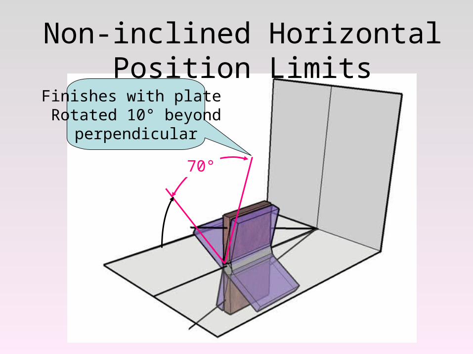
Non-inclined Horizontal Position Limits
Starts with plate Rotated 30°
70°
Non-inclined Horizontal Position Limits
Finishes with plate Rotated 10° beyond
perpendicular
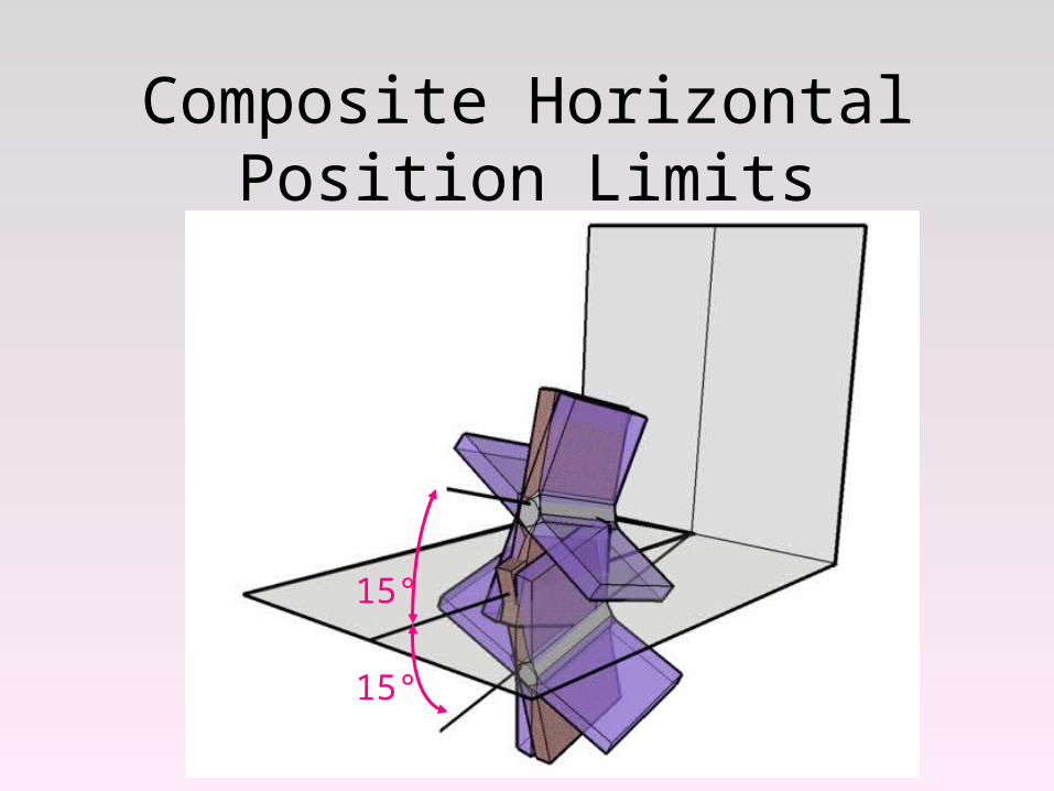
Composite Horizontal Position Limits
15°
15°
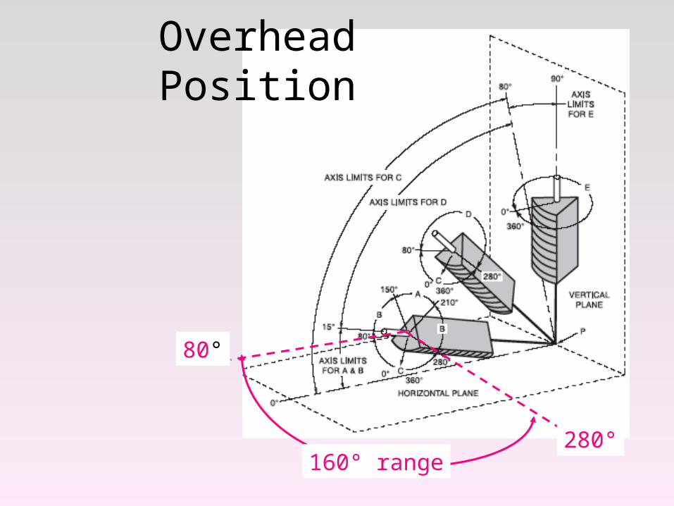
80°
280°
Overhead Position
160° range
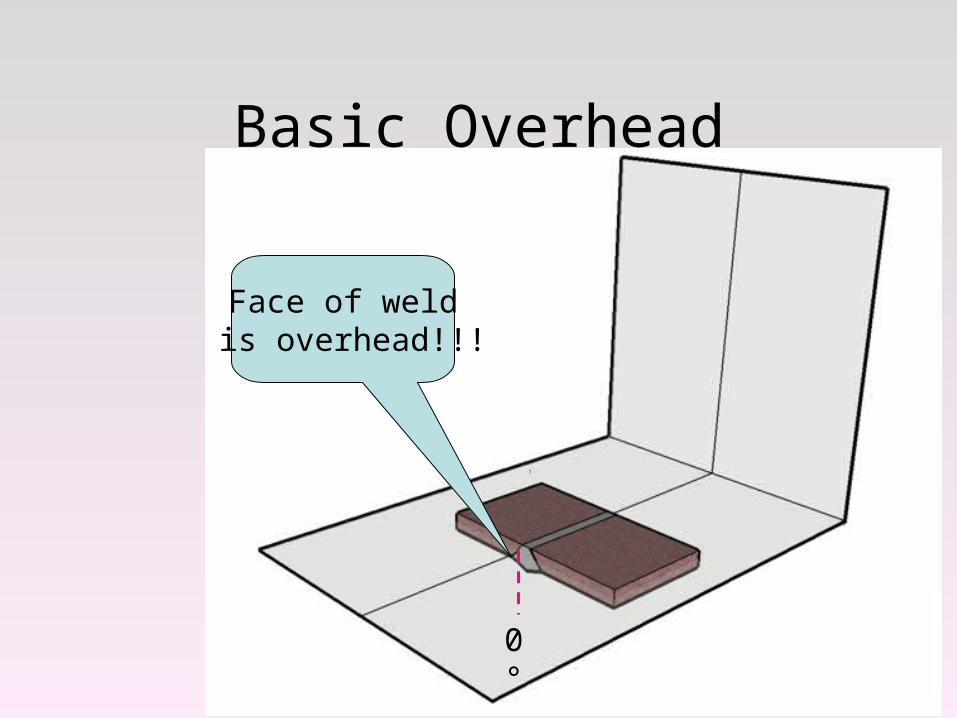
Basic Overhead
Face of weld is overhead!!!
0°
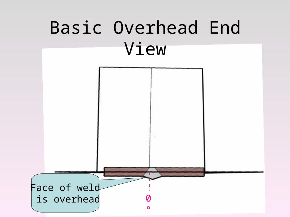
Basic Overhead End View
Face of weld is overhead 0°
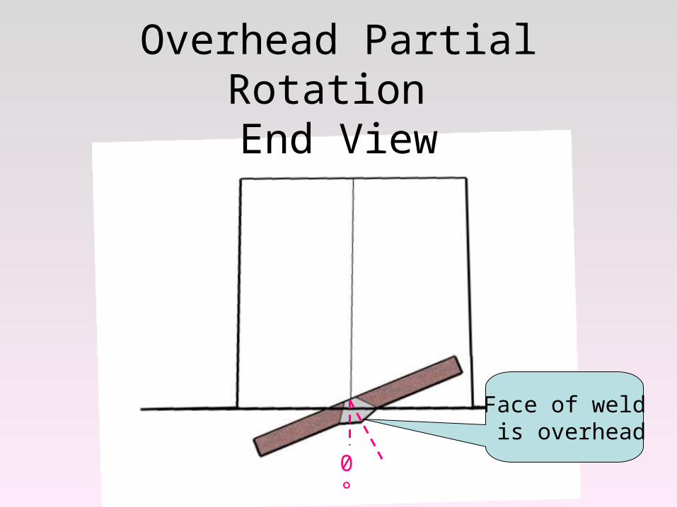
Overhead Partial Rotation End View
Face of weld is overhead
0°
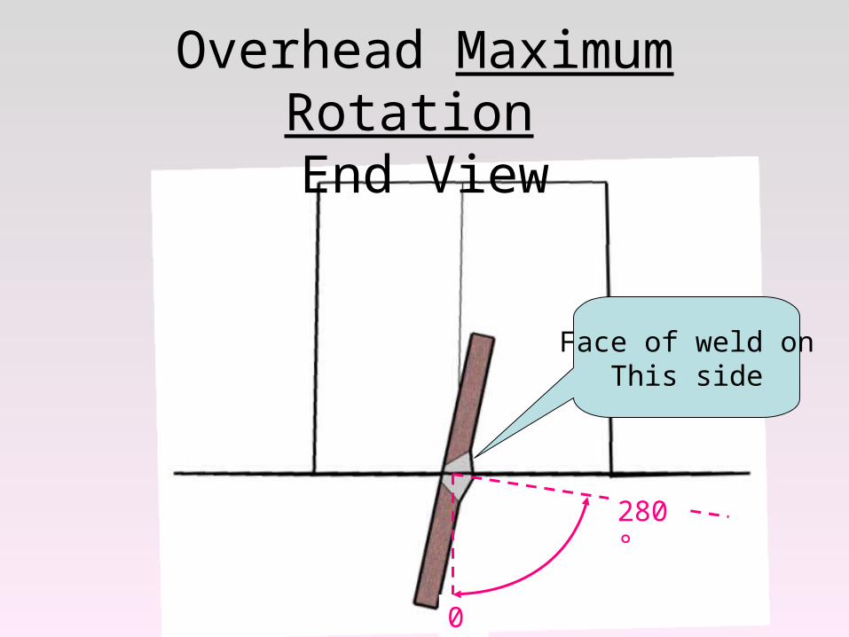
Overhead Maximum Rotation End View
0°
280°
Face of weld onThis side
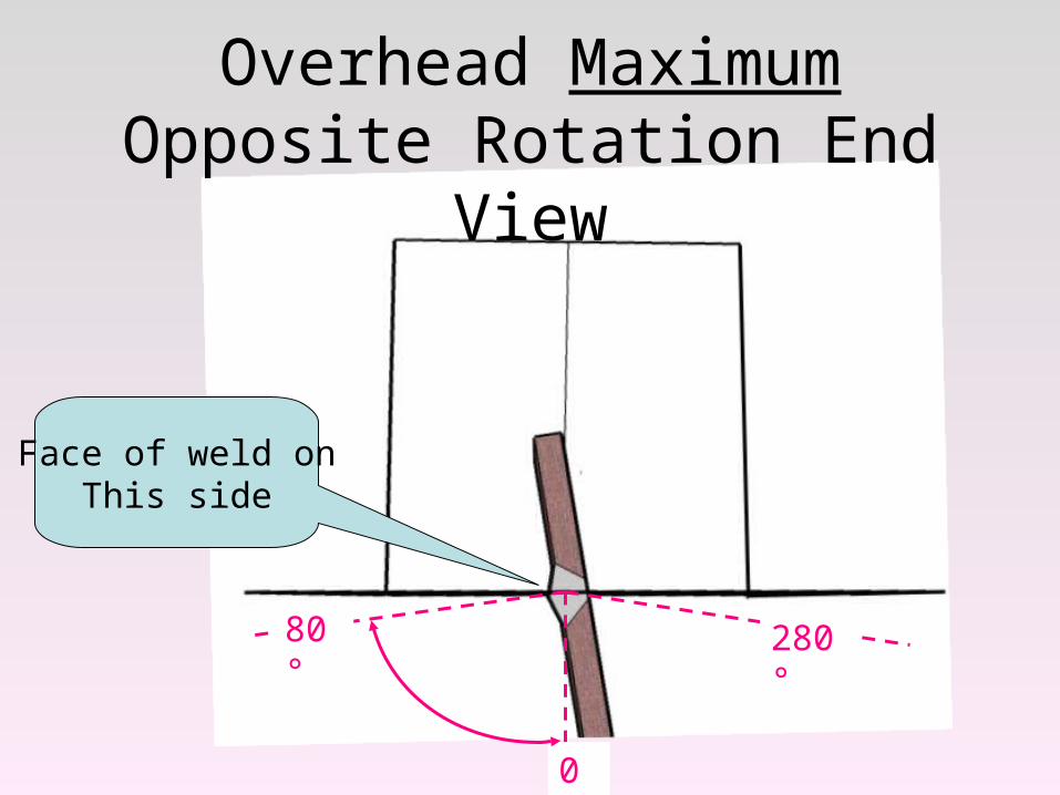
Overhead Maximum Opposite Rotation End View
0°
280°80°
Face of weld onThis side
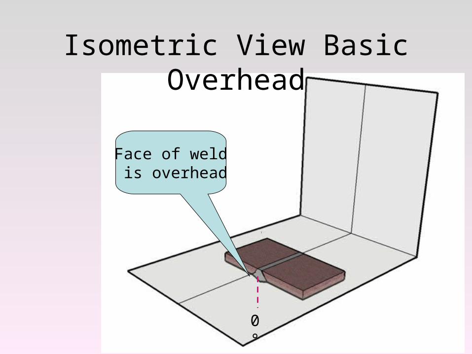
Isometric View Basic Overhead
Face of weld is overhead
0°
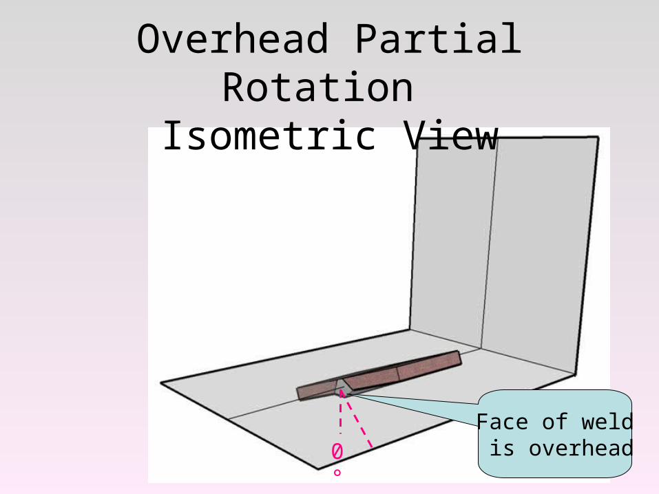
Face of weld is overhead
Overhead Partial Rotation Isometric View
0°
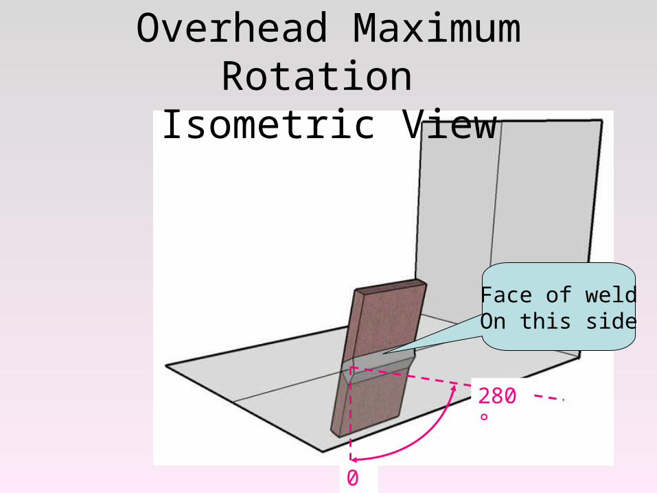
Overhead Maximum Rotation Isometric View
0°
280°
Face of weldOn this side
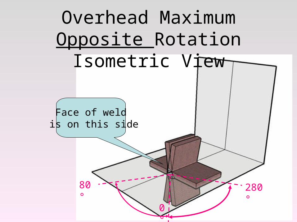
Overhead Maximum Opposite Rotation Isometric View
0°
280°80°
Face of weld is on this side
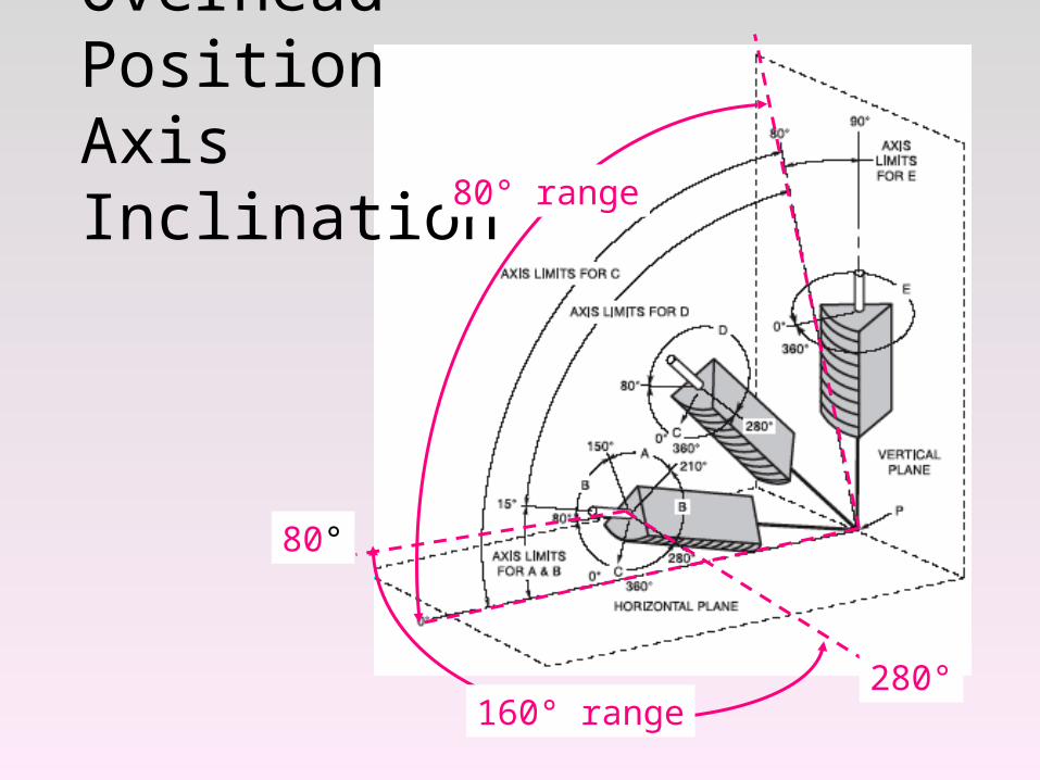
Overhead PositionAxis Inclination
80°
280°160° range
80° range
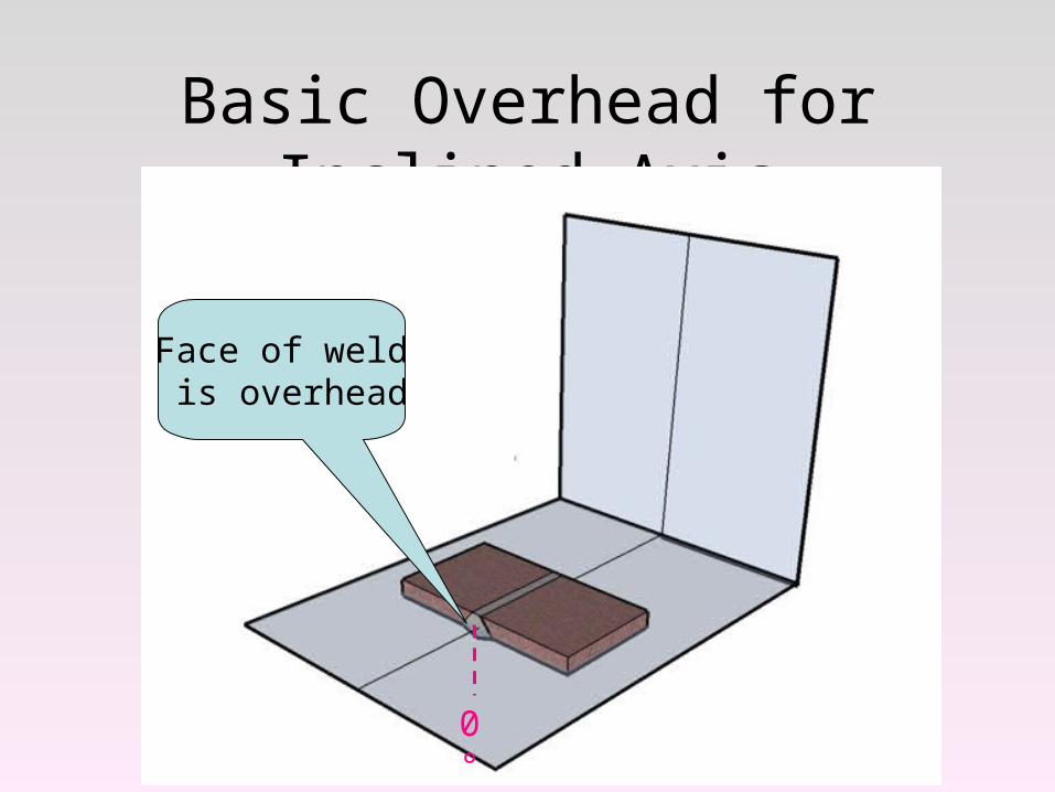
Basic Overhead for Inclined Axis
Face of weld is overhead
0°
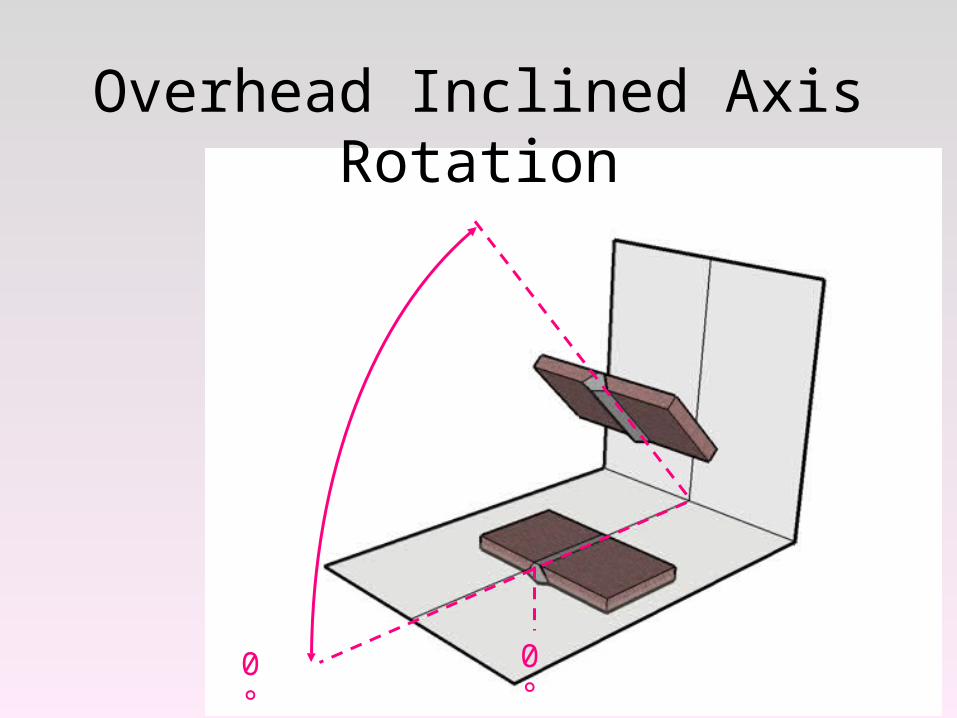
Overhead Inclined Axis Rotation
0°0°
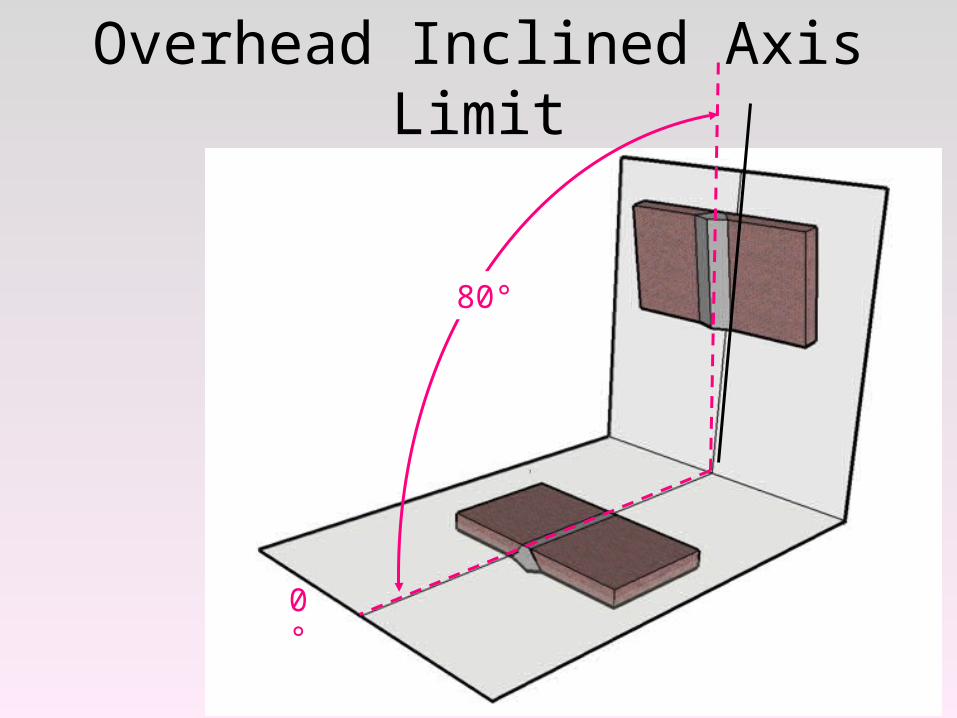
Overhead Inclined Axis Limit
0°
80°
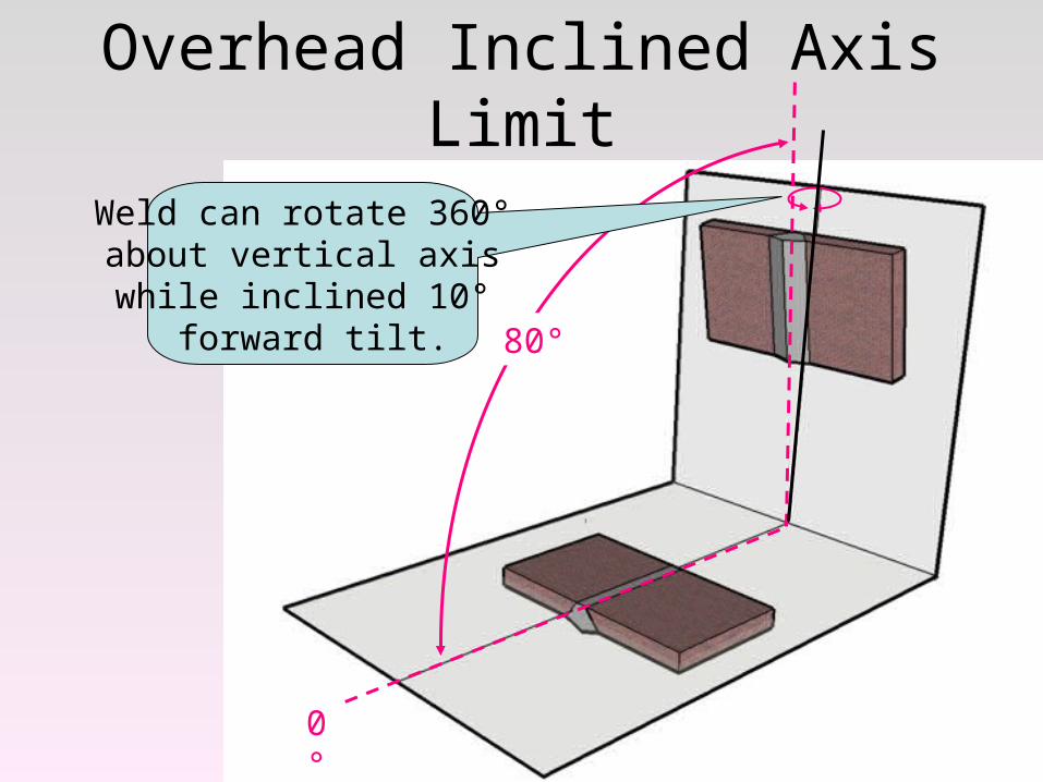
Overhead Inclined Axis Limit
0°
80°
Weld can rotate 360° about vertical axis while inclined 10°
forward tilt.
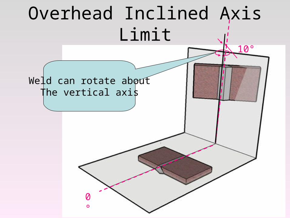
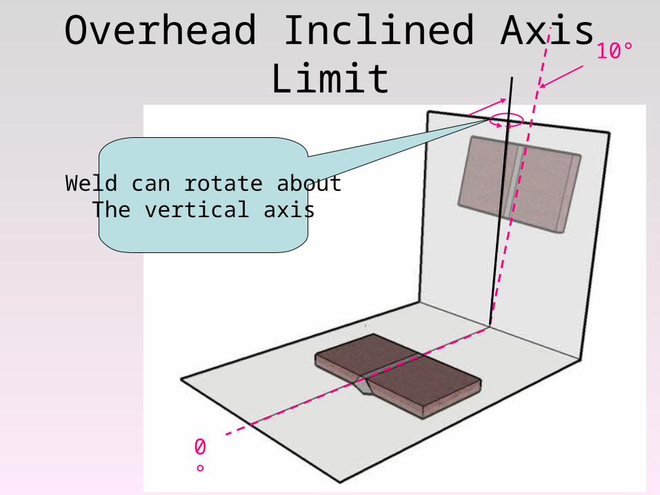
Overhead Inclined Axis Limit
0°
Weld can rotate aboutThe vertical axis
10°
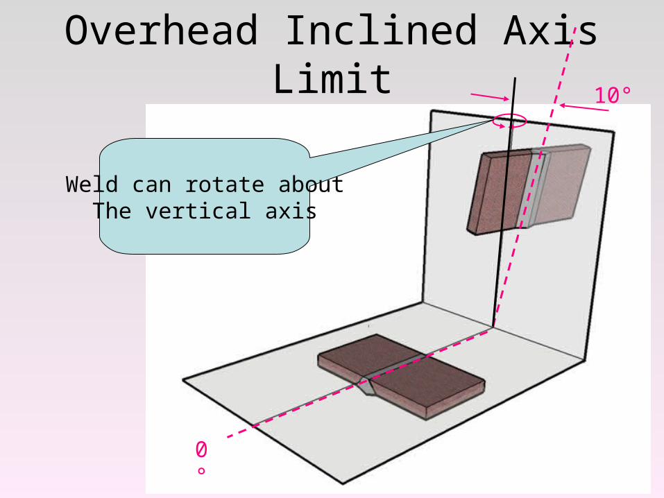
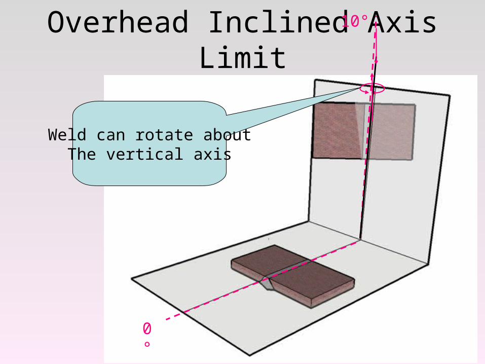
Overhead Inclined Axis Limit
0°
Weld can rotate aboutThe vertical axis
10°
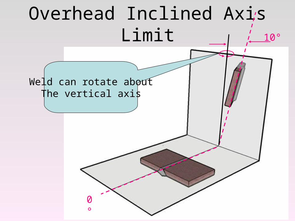
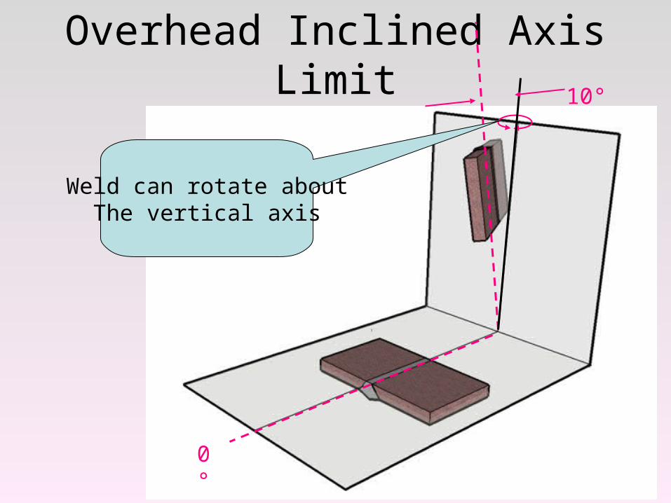
Overhead Inclined Axis Limit
0°
Weld can rotate aboutThe vertical axis
10°
Overhead Inclined Axis Limit
0°
Weld can rotate aboutThe vertical axis
10°
Overhead Inclined Axis Limit
0°
Weld can rotate aboutThe vertical axis
10°
Overhead Inclined Axis Limit
0°
Weld can rotate aboutThe vertical axis
10°
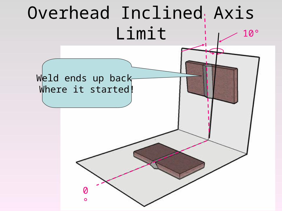
Overhead Inclined Axis Limit
0°
Weld ends up back Where it started!
10°
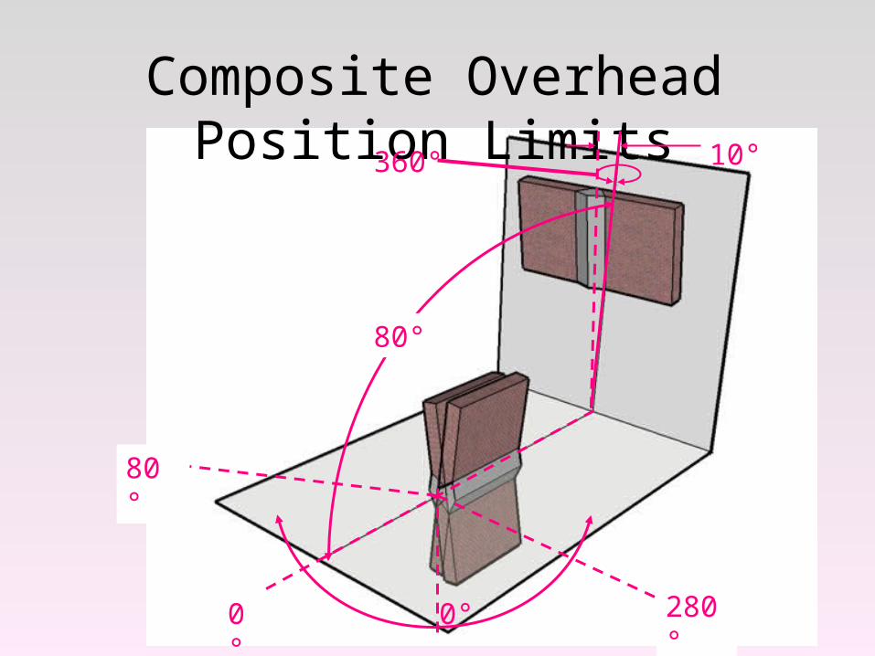
Composite Overhead Position Limits
280°
80°
0°0°
80°
360° 10°
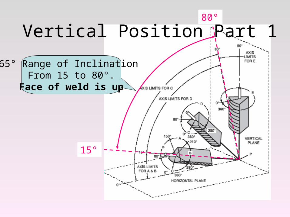
Vertical Position Part 1
65° Range of Inclination From 15 to 80°.
Face of weld is up
15°
80°
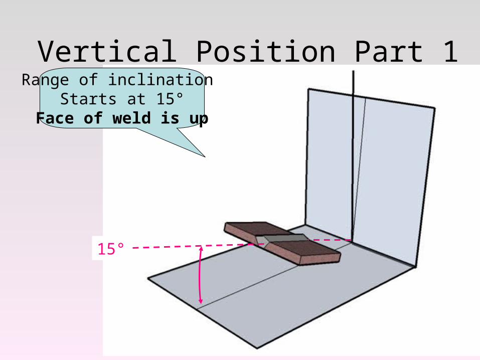
Vertical Position Part 1Range of inclination
Starts at 15°Face of weld is up
15°
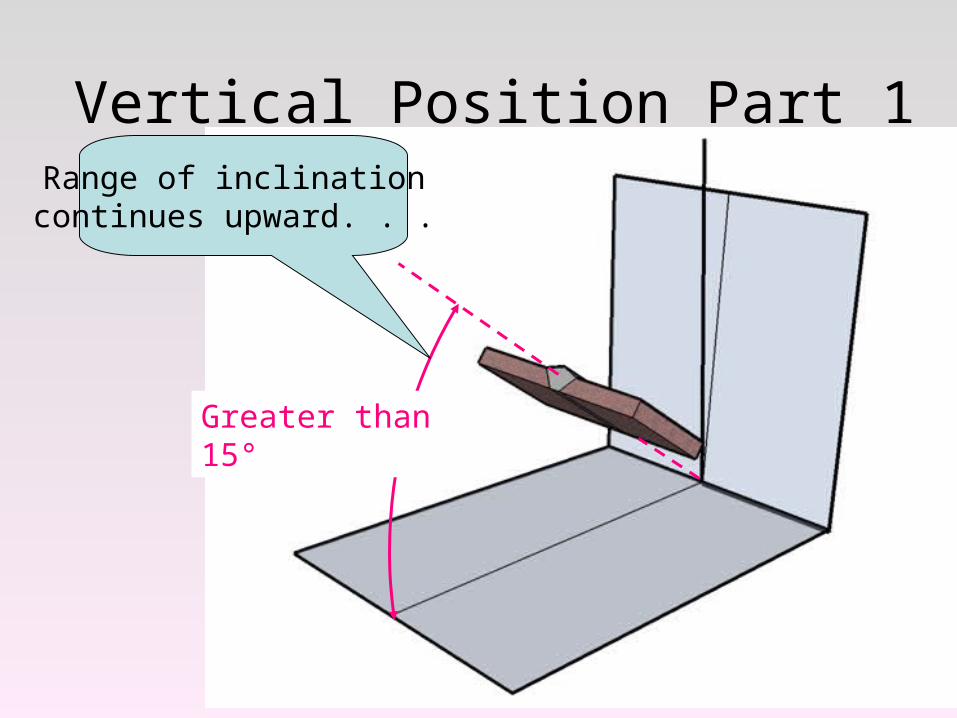
Vertical Position Part 1Range of inclination continues upward. . .
Greater than 15°
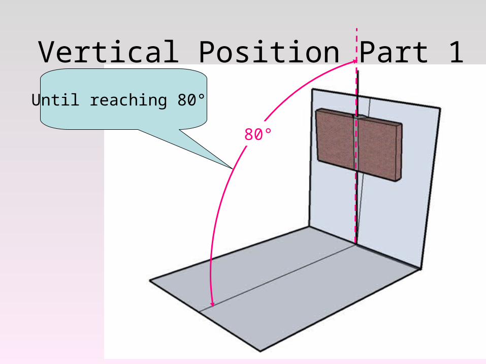
Vertical Position Part 1
Until reaching 80°
80°
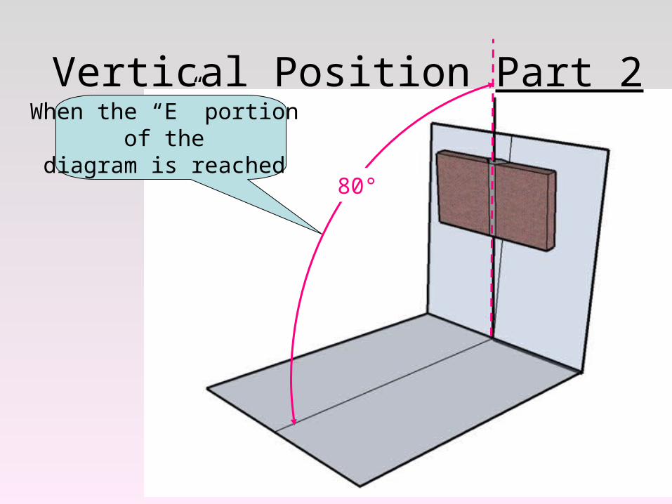
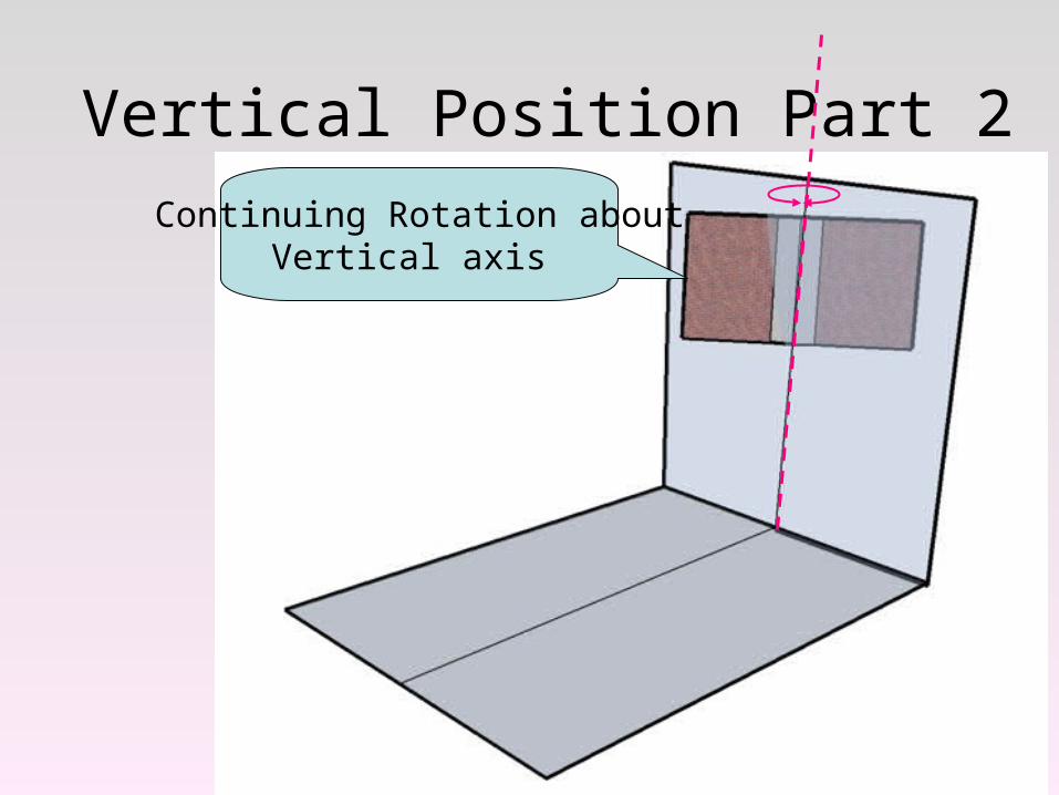
Vertical Position Part 2When the “E” portion
of the diagram is reached
80°
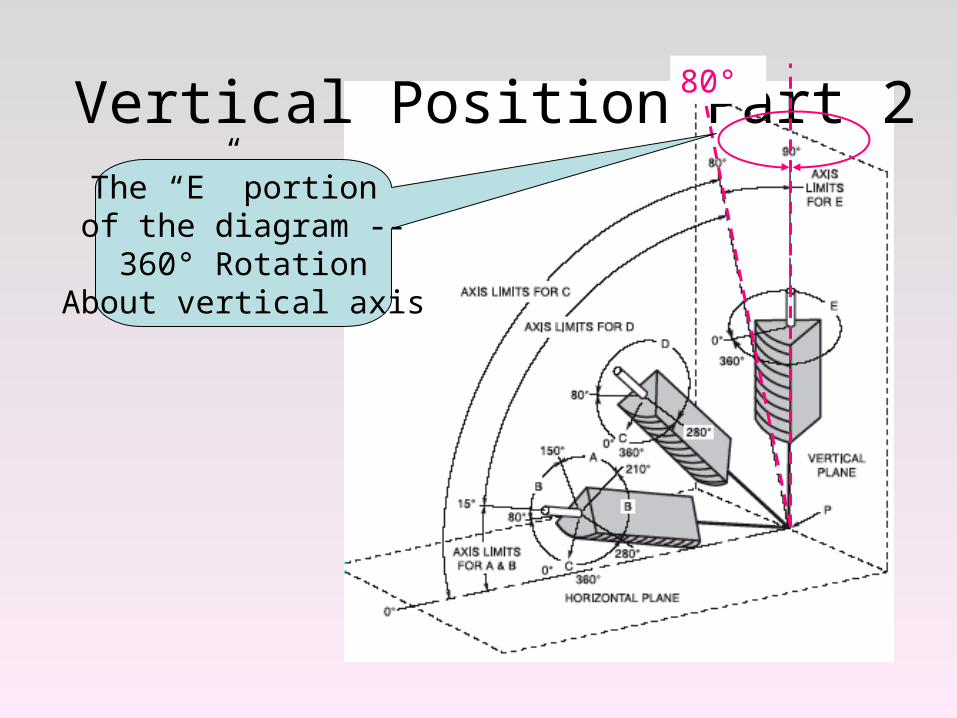
Vertical Position Part 2The “E” portion of the diagram --
360° RotationAbout vertical axis
80°
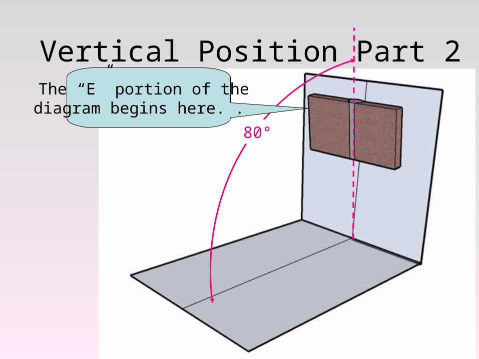
Vertical Position Part 2The “E” portion of the diagram begins here. .
80°
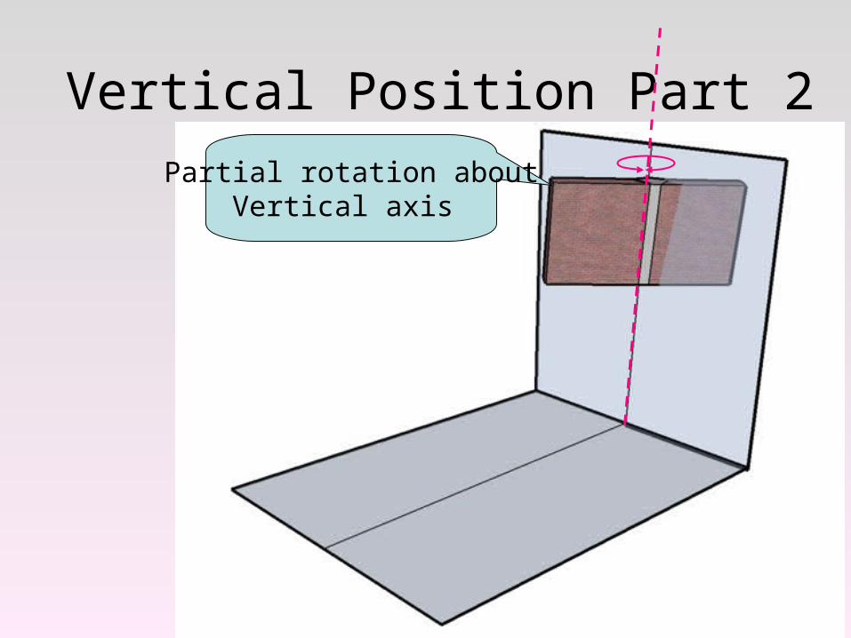
Vertical Position Part 2
Partial rotation aboutVertical axis
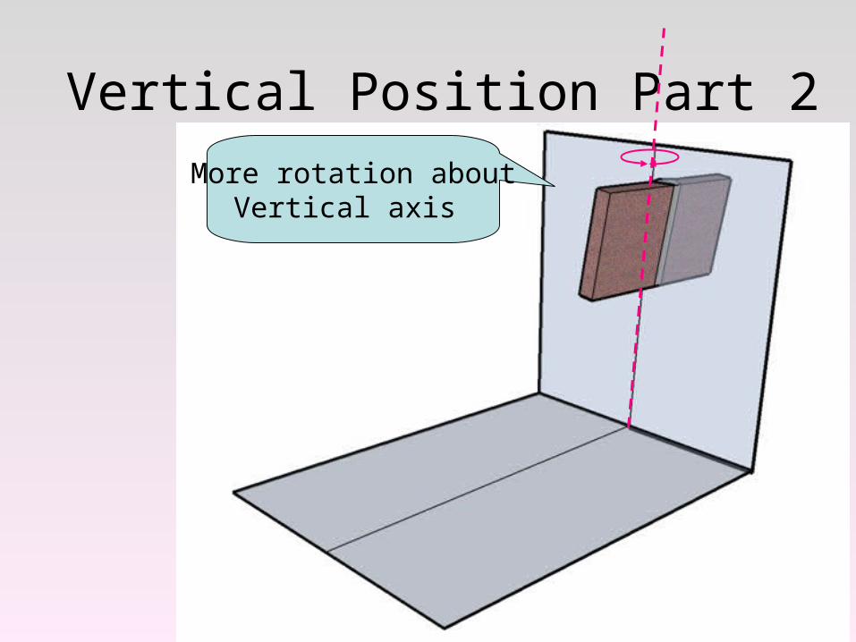
Vertical Position Part 2
More rotation aboutVertical axis
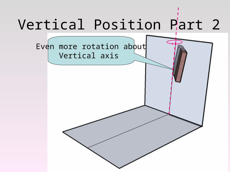
Vertical Position Part 2
Even more rotation aboutVertical axis
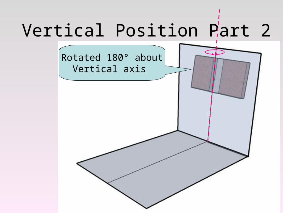
Vertical Position Part 2
Rotated 180° aboutVertical axis
Vertical Position Part 2
Continuing Rotation aboutVertical axis
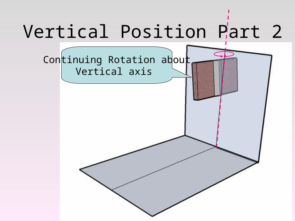
Vertical Position Part 2
Continuing Rotation aboutVertical axis
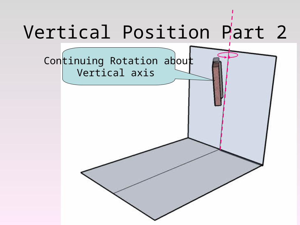
Vertical Position Part 2
Continuing Rotation aboutVertical axis
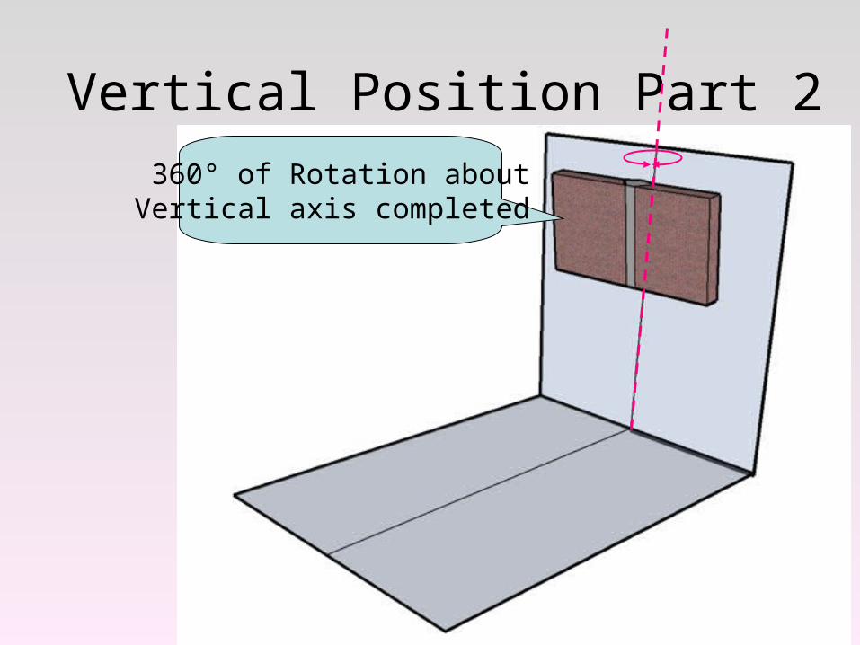
Vertical Position Part 2
360° of Rotation aboutVertical axis completed
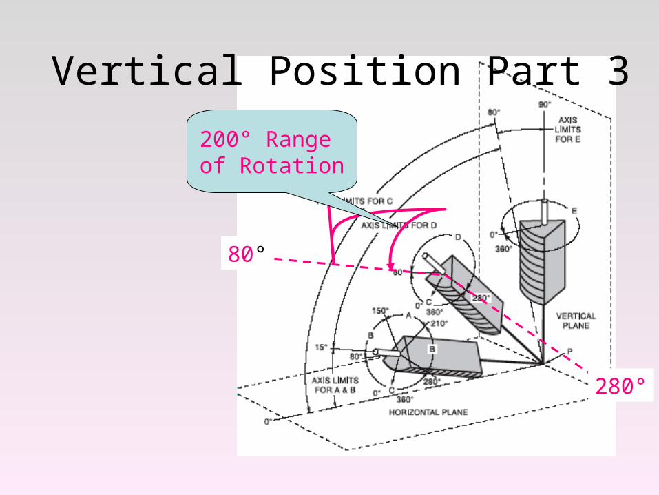
Vertical Position Part 3
80°
280°
200° Range of Rotation
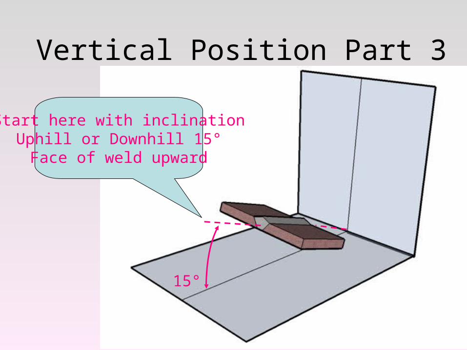
Vertical Position Part 3
Start here with inclinationUphill or Downhill 15°Face of weld upward
15°
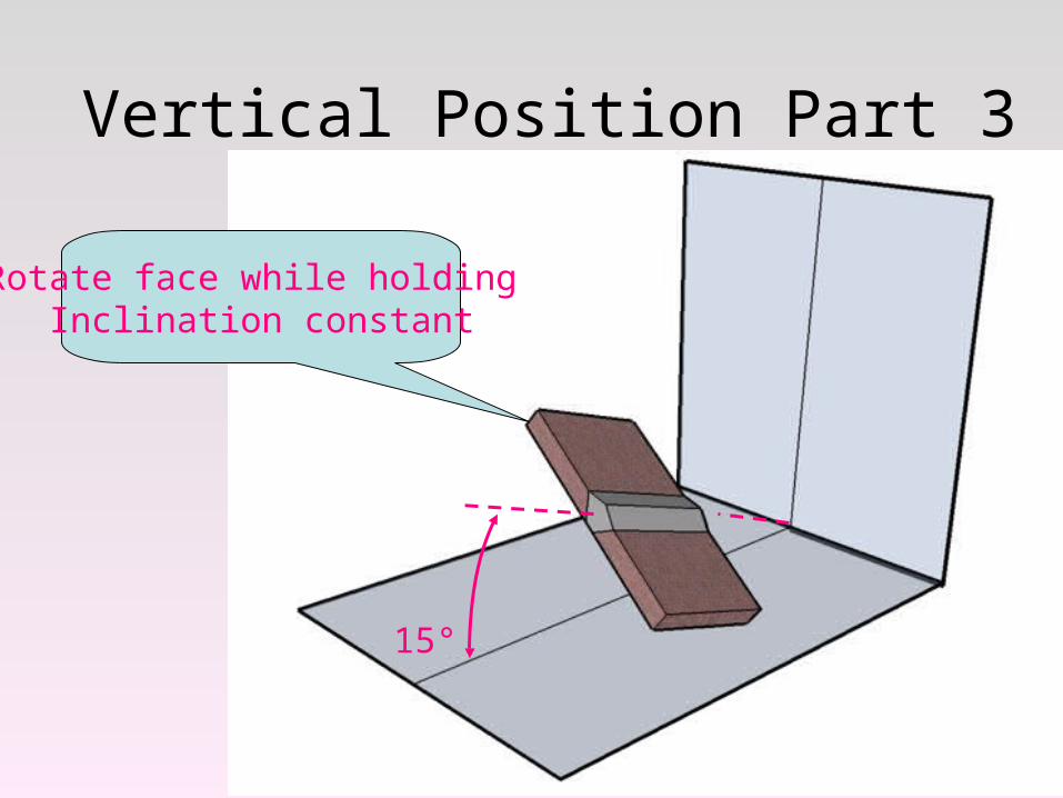
Vertical Position Part 3
Rotate face while holding Inclination constant
15°
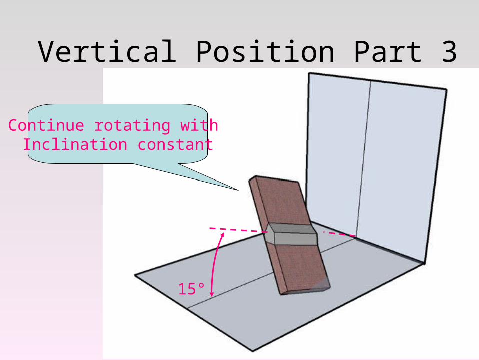
Vertical Position Part 3
Continue rotating with Inclination constant
15°
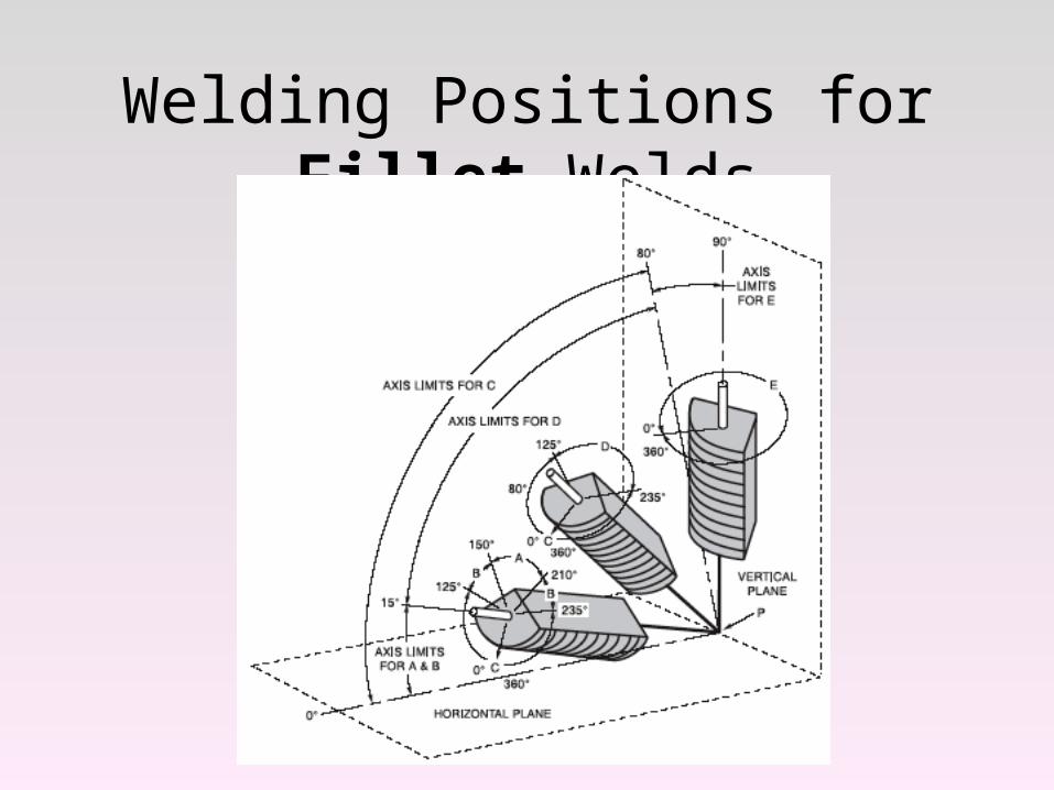
Welding Positions for Fillet Welds
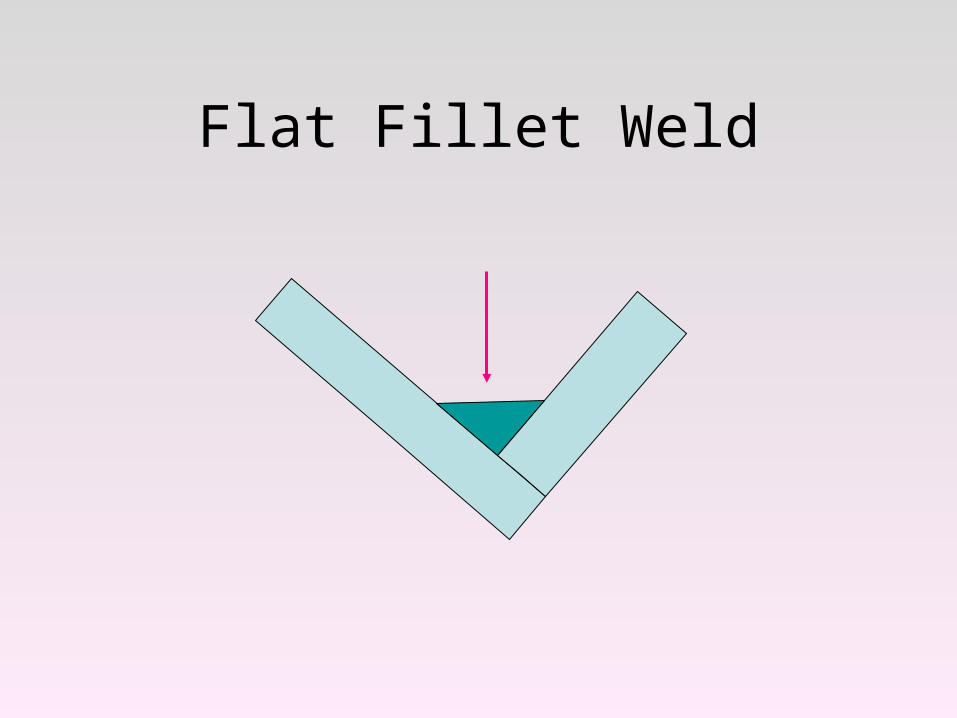
Flat Fillet Weld
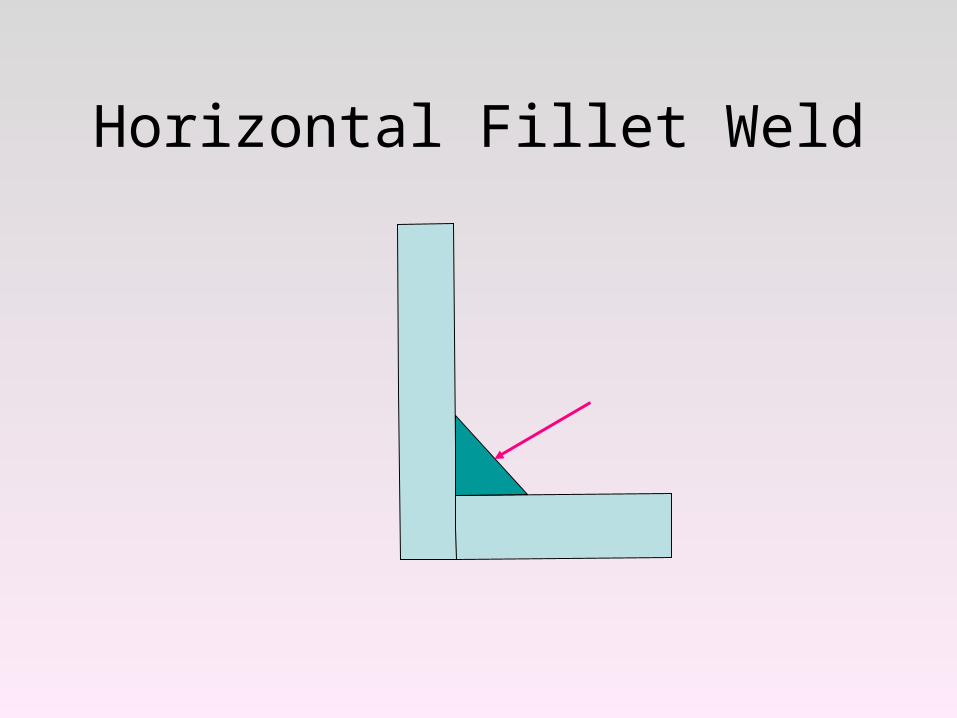
Horizontal Fillet Weld
Welding Positions for Fillet Welds
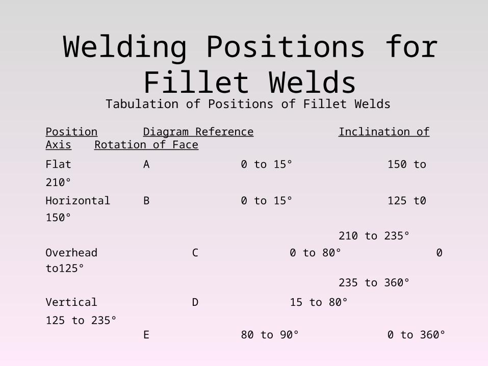
Welding Positions for Fillet WeldsTabulation of Positions of Fillet Welds
Position Diagram Reference Inclination of Axis Rotation of Face
Flat A 0 to 15° 150 to 210°
Horizontal B 0 to 15° 125 t0 150°
210 to 235°
Overhead C 0 to 80° 0 to125°235 to 360°
Vertical D 15 to 80° 125 to 235°E 80 to 90° 0 to 360°
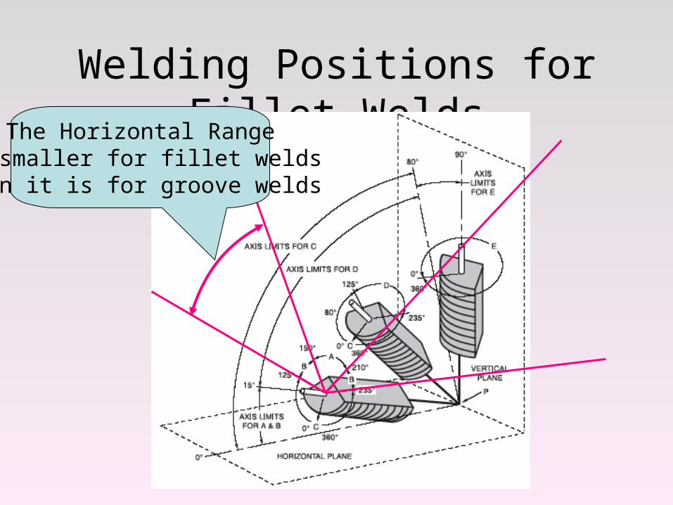
Welding Positions for Fillet WeldsThe Horizontal Range
Is smaller for fillet weldsThan it is for groove welds
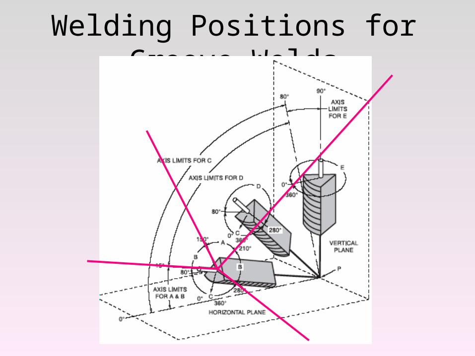
Welding Positions for Groove Welds


![[PPT]Welding Techniques and Defects - Tun Hussein Onn …author.uthm.edu.my/uthm/www/content/lessons/2475/Kimpalan... · Web viewSMAW Pipe Welding Techniques Positions 1G 2G 5G 6G](https://img.pdfslide.net/doc/110x75/5afd373f7f8b9a68498c8df9/pptwelding-techniques-and-defects-tun-hussein-onn-viewsmaw-pipe-welding.jpg)