Embed Size (px)
Citation preview

ENVIRONMENTAL ENGINEERINGSTANDARDS
Issue 1 – Operative from 1 June 2007
Whangarei District Council
TABLE OF CONTENTS
i
1. GENERAL REQUIREMENTS AND PROCEDURES 71.1 General Requirements 7
1.2 Definitions 8
1.3 Applicability 12
1.4 General Design Requirements 12
1.5 Drafting Standards 14
1.6 Content of Drawings 16
1.7 As-Built Drawings, schedules of Asset Information and Operation and Maintenance Manuals 18
1.8 RAMM Data Requirements 19
1.9 Registered Contractors and LICENSED Contractors 20
1.10 Colour of Pipes and Ducts 20
1.11 Protection of Existing Services and Repair of Damage 21
1.12 Emergency Procedure 21
1.13 Particular Requirements for Resource Consent Applications 21
2. SITE SUITABILITY AND EARTHWORKS 292.1 General Requirements 29
2.2 Referenced Documents 29
2.2 Technical Requirements 29
2.3 Landform 31
2.4 Compaction of Fill Material 32
2.5 Erosion, Sediment and Dust Control 32
2.6 Report on Completion of Construction 32
3. ROADS AND ACCESS 333.1 General Requirements 33
3.2 Referenced Documents 33
3.3 Submission of application 34
3.4 Design Requirements 34
3.5 Geometric Design 40
3.6 Pavement structural design 41
3.7 Intersection Design 42
3.8 Cul de Sac Heads 42
3.9 Berms, Footpaths etc 43
3.10 Vehicle Crossings 44
3.11 Private Accessways 45
3.12 Traffic Services, Signage, and Road Furniture 45
3.13 Road Names 46
3.14 Street Lighting 46
3.15 Bridges and Culverts 46
TABLE OF CONTENTS
ii
3.16 Road Drainage 48
3.17 Road Construction 49
3.18 Surfacing 51
3.19 Surface Tolerances and Finishing 52
3.20 Completion 52
3.21 Defects Liability 53
3.22 Drawings 53
4. STORMWATER DRAINAGE 554.1 General Requirements 55
4.2 Referenced Documents 55
4.3 Submission of application 56
4.4 Stormwater Assessment Strategy 56
4.5 Low-Impact Design and Stormwater Treatment 57
4.6 Northland Regional Council Authorisation 58
4.7 Primary and Secondary Systems 58
4.8 Level of Service 59
4.9 Pipe Selection 61
4.10 Layout of Reticulation 62
4.11 System Components 63
4.12 Design 66
4.13 Stormwater Quality Control 68
4.14 Inspection and Testing 68
4.15 Completion 69
4.16 Defects Liability 69
4.17 Drawings 69
5. WASTEWATER RETICULATION AND TREATMENT 715.1 General Requirements 71
5.2 Referenced Documents 71
5.3 Submission of application 71
5.4 Wastewater Treatment and Disposal 72
5.5 Consents 73
5.6 Level of Service 73
5.7 Pipe Selection 74
5.8 Design Flow 75
5.9 Layout of Reticulation 78
5.10 Maintenance structures 80
5.11 Pump Stations 84
5.12 Odour Control 87
5.13 Contractor Qualifications 88
5.14 Inspection and Testing 88
TABLE OF CONTENTS
iii
5.15 Completion 89
5.16 Defects Liability 89
5.17 Drawings 90
6. WATER SUPPLY AND RETICULATION 916.1 General Requirements 91
6.2 Referenced Documents 91
6.3 Submission of application 91
6.4 Level of Service 92
6.5 Scope of Design 93
6.6 Pipe Selection 94
6.7 Flow Capacity 96
6.8 Layout of Reticulation 98
6.9 Valves and Fittings 101
6.10 Valve Marking 103
6.11 Hydrants 103
6.12 Surface Boxes 104
6.13 Bulk Water Meters 104
6.14 Service Connections 104
6.15 Pump Station and Reservoirs 106
6.16 Contractor Qualifications 106
6.17 Pipeline Construction 107
6.18 Disinfection and Testing 109
6.19 Completion 111
6.20 Defects Liability 112
6.21 Drawings 112
7. RESERVES AND LANDSCAPE DESIGN AND PRACTICE 1137.1 General Requirements 113
7.2 Referenced Documents 113
7.3 Submission of application 113
7.4 General 113
7.5 Design 115
7.6 Construction 117
7.7 Completion 117
7.8 Defects Liability 118
8. POWER, TELECOMMUNICATIONS AND GAS 119
8.1 General Requirements 119
8.2 Design Drawings 119
8.3 Electricity 119
8.4 Telecommunications 119

Environmental Engineering StandardsIssue 1 - June 2007Section 1 General
Page 7
WHANGAREI DISTRICT COUNCILENVIRONMENTAL ENGINEERING STANDARDS
1. GENERAL REQUIREMENTS AND PROCEDURES
1.1 GENERAL REQUIREMENTS
1.1.1 GeneralThese Engineering Standards: Provide a means of compliance with the Rules and Performance Criteria of the Whangarei
District Council District Plan for subdivision and development, and Specify minimum acceptable requirements for the design and construction of Council
infrastructure.
The main purposes of the Standard are to ensure that: Assets to be vested in Council achieve acceptable levels of service (capacity, maintainability and
useful working life), Subdivisions and developments comply with the requirements of the District Plan, Assets that remain in private ownership achieve acceptable levels of service, Council has accurate records of the assets installed.
The goal is to achieve public assets that are current best-practice, cost-effect, and durable.
This Standard should be read in conjunction with relevant New Zealand Standards (in particular,NZS 4404:2004) and other referenced documents in this standard. Where requirements differ, theEnvironmental Engineering Standards shall take precedence.
Further mandatory engineering stipulations are required by legislation, Northland Regional Councilregional plans and the NZ Building Code. Developers shall comply with the requirements of thesedocuments.
1.1.2 Statutory requirementsThe provisions of this standard shall be read subject to the provisions of the District Plan, and allapplicable statutes, regulations and bylaws, including: Building Act 2004, Electricity Act 1992 and Amendments, Health and Safety in Employment Act 1992 Land Transfer Act 1952, Local Government Acts 1974 and 2002, Plumbers, Gasfitters and Drainlayers Act 1976, Public Works Act 1981, Resource Management Act 1991, Telecommunications Act 2001, Transit New Zealand Act 1989, Transport Management Act 2003, Water Supplies Protection Regulations 1961.
Environmental Engineering StandardsIssue 1 - June 2007Section 1 General
Page 8
1.1.3 Health and SafetyAll work carried out on Council Assets, or on public land shall strictly comply with the WhangareiDistrict Council ‘Health and Safety Policy and Procedure’. This document is available from theCouncil.
Where the Council is not the Principal (e.g. work is carried out by a developer), all Contractorsworking within public land, and/or on Council assets are required to complete/comply with thefollowing requirements of the Policy:
Forms H&S003, H&S004, Provide a copy of their Occupational Safety Policy or WDC Approved Health and Safety
Contractors Certificate. Comply with H&S005, including providing a Traffic Management Plan in a format that is
consistent with TNZ Code of Practice for Temporary Traffic Management in New Zealand(Current Edition) where work will be carried out within a road.
Comply with H&S006.
No work on Council Assets, or on any public land shall proceed before the above has been compliedwith, and approved by the Council. The Council reserves the right to refuse to allow a contractorthat in its opinion may not comply with all Health and Safety requirements, to carry out work onCouncil Assets, or on public land.
1.2 DEFINITIONS
ANNUALEXCEEDANCEPROBABILITY (AEP)
The probability of exceedance of an event (generally a storm) within aperiod of one year. (1% AEP is equivalent to 1 in 100 years storm).
ARTERIAL ROAD Major roads with high traffic volumes or a significant component ofthrough traffic. These include major roads into and through the Districtand roads serving significant areas of development. Existing arterial roadsare shown on District Plan maps.
COLLECTOR ROAD Roads that collect traffic from specific areas, or link important roads ormajor traffic generators. Existing collector roads are shown on District Planmaps.
COMMERCIAL ANDINDUSTRIAL AREA
Land within Business 1, Business 2, Business 3, Business 4 (including OilRefinery and Kauri Dairy Factory), Marsden Point Port and AirportEnvironments.
COMMUNITYSEWERAGE SYSTEM
A wastewater reticulation, treatment and disposal system that serves two ormore properties. This applies irrespective of whether or not it ismaintained by Council.
COUNCIL The Whangarei District Council
CYCLEWAY The part of a road that is laid-out or constructed primarily for cyclists. Itmay include the associated edging, kerb and channel.

Environmental Engineering StandardsIssue 1 - June 2007Section 1 General
Page 9
DEVELOPER In relation to resource consent applications, is the person, organisation orlegal entity who/that has the financial responsibility for the developmentproject. It includes the owner.
DEVELOPERSPROFESSIONALADVISOR
The person or persons appointed by the developer who shall be responsiblefor: Investigation, design and obtaining approvals for the work, Contract administration and supervision of the works, Certification on completion of the works.
DISTRICT PLAN The operative and proposed plans for the Whangarei District and anycombination of them applicable to a resource consent application.
DRAIN A pipe or channel that conveys sewage or stormwater flow.Drainage has a corresponding meaning.
EARTHWORKS Any alteration to the contours of the ground by excavation, backfilling orrecompaction of existing natural ground and the stripping of vegetation andtopsoil. It includes: quarrying prospecting and exploration the disturbance of land surfaces by moving, removing, placing or
replacing soil or earth, or by excavation, cutting or filling operations contouring road, driveway and other access construction clean fill operations,
It does not include: horticulture gardening for domestic purposes work carried out to provide for effluent disposal systems or pile
foundations for residential buildings, trenching work for the installation or maintenance of infrastructure
FOOTPATH The part of a road that is laid out or constructed primarily for pedestrians.It may include the associated edging, kerb and channel.
GEOTECHNICALENGINEER
A Chartered Professional Engineer (CPEng) or an engineering geologist,with recognised qualifications and experience in geotechnical engineering,and experience related to the development.
GROUND The material in the vicinity of the surface of the earth whether soil or rock.
DWELLING UNIT(DU) ORHOUSEHOLD UNITEQUIVALENT (HUE)
A building or group of buildings or part thereof principally used forresidential purposes by a single household.A Household Unit Equivalent is the demand on infrastructure servicescreated by an average household unit.The Whangarei District Council ‘Development Contributions Policy’defines the assumptions as to the demand created by one HUE (AppendixC of the Policy), and factors to be applied for non-residential developments(Appendices D and F of the Policy).
Environmental Engineering StandardsIssue 1 - June 2007Section 1 General
Page 10
INDEPENDENTQUALIFIED PERSON(IQP)
A specialist approved by the Council, having the appropriate skills andqualifications to carry out specific procedures. Refer to Section 1.4 of thisStandard.
INDUSTRIALPREMISES
a) Any premises used for industrial or trade purposes or that is used for thestorage, transfer, treatment or disposal of waste materials, for otherwaste management purposes, or for the composting of organic material;
b) Any factory farm (such as battery pig or poultry farms, cattle feed lots).
LAND DRAINAGESYSTEM
The system of drainage that controls surface and subsurface flow. It ismainly used for peak surface flows in urban areas.
LEGAL WIDTH FORROADS
For public roads, this is the width of the strip of land that has been declaredroad in accordance with section 114 of the Public Works Act, 1981. Forprivate roads, private ways or easements (rights-of-way), it is the width ofthe strip of land over which the public, shared owners or landowners withdominant tenement are legally entitled to pass without the specific approvalof any one landowner. The term “legal road” is interchangeable with theterm “road reserve”.
LICENSEDCONTRACTOR
A specialist contractor who has been Licensed by the Whangarei DistrictCouncil to perform a particular type of work on Council Assets, that onlyLicensed Contractors are permitted to perform (e.g. live connections toexisting water reticulation). Normally only a limited number of contractorswill be licensed at any one time.
LOCAL ROAD Roads not classified as arterial or collector, whose major function is toprovide access to properties rather than provide routes for traffic.
MEANS OFCOMPLIANCE
A method by which the requirements of the standard may be compliedwith.
NETWORK UTILITYOPERATOR
Has the same meaning as given to it by Section (s.) 166 of the ResourceManagement Act 1991.
OWNER Includes an owner of land, whether beneficially or as trustee, and theiragent or attorney, and a mortgagee acting in exercise of power of sale. Italso includes the Crown, the Public Trustee, and any person, localauthority, board or other body or authority however designated, constitutedor appointed, having power to dispose of the land or interest therein by wayof sale.
PAVEMENT The layer(s) of a road structure above the subgrade, incorporating subbaseand/or basecourse crushed granular material whether chemically stabilisedor not, or rigid material (such as concrete), but excluding any seal coat.
PRIMARY DESIGNFLOW
The estimated stormwater run-off selected to provide a reasonable degreeof protection to surrounding land and buildings. This flow will generallybe piped or contained within narrow confines, under public control byreserve or easement.
Environmental Engineering StandardsIssue 1 - June 2007Section 1 General
Page 11
PRINCIPAL WATERMAINS
All water reticulation 100mm in diameter or greater. Includes associatedvalves.
PRIVATE ROAD Any roadway, place, or arcade laid out within a district on private landintended for the use of the public generally.
PRIVATE WAY /PRIVATEACCESSWAY
A road or passage over private land which is not open or intended to beopen to general public use. (See also District Plan definitions).
REGISTEREDCONTRACTOR
A contractor who has obtained approval from the Whangarei DistrictCouncil to construct or modify assets that are owned or will be taken overby the Council, and has been added to Council’s official list of RegisteredContractors. Registration is restricted to the type of work for whichapproval has been given. Reference should be made to the WhangareiDistrict Council Procedures and Specifications for Registered Contractors.
RIDER MAIN Water reticulation less than 100mm in diameter that serves more than oneproperty. Includes associated valves.
RISING MAIN Wastewater pressure reticulation between a pump station and non-pressurised junction or termination including another pump station,manhole, reservoir or treatment system.
ROAD OR STREET Has the same meaning as “road” as defined by Section 315 of the LocalGovernment Act 1974.
RURAL AREA Land within Countryside, Coastal Countryside or Living 3 Environments.Where a Resource Consent allows small lot sizes within theseEnvironments, the Council may require ‘Urban’ standards to be applied.
SECONDARY OROVERLAND FLOWPATH
Refers to the path taken by runoff in excess of the primary design flow,which has the purpose of preventing inundation of surrounding buildingsites.A freeboard above the secondary flow level is required to cater forinaccuracies in flow estimation and possible failure of the primary system.
SERVICE LANE Has the meaning given in section 315 of the Local Government Act.
SERVICE PIPES(WATER)
Pipes located between a water meter and a building with the purpose ofsupplying water to a single property. Service pipes are installed andmaintained by the owner.
SEWER An enclosed pipe used for conveying sewage by gravity.
SPECIFIC DESIGN A design that requires calculation and design, either using a methodreferenced in this standard, or outside of the scope of methods used in thisstandard.
Specific designs shall be prepared by a person suitably qualified withadequate expertise and experience in accordance with sound and acceptedengineering practice and principles and that meets the objectives set out in

Environmental Engineering StandardsIssue 1 - June 2007Section 1 General
Page 12
these standards and/or the District Plan. The design shall comply withNew Zealand Standard specifications and/or other nationally recognisedprocedure and systems.
STABLE GROUND Ground that, in the opinion of a suitably qualified and experiencedgeotechnical engineer, is in a state which is unlikely to settle, slip, erode orotherwise move to the detriment of superimposed buildings, services, roadsor property generally.
STORMWATER Rain water that flows via overland flow, channels or pipes.
SURVEY PLAN A survey plan in terms of s.2 of the Resource Management Act 1991.
URBAN AREA Land within Living 1 and Living 2 Environments and allBusiness/Commercial/Industrial Environments.
1.3 APPLICABILITYSections 1.4 to 1.12 inclusive are applicable to all infrastructure design and construction. Section1.13 gives requirements particular to Resource Consent applications. For infrastructure design andconstruction commissioned by the Whangarei District Council, specific conditions ofengagement/contract will apply.
1.4 GENERAL DESIGN REQUIREMENTS
1.4.1 Investigation and DesignAll investigation, calculations, design, supervision and certification of the works outlined in thisStandard shall be carried out by or under the control of persons who: Are experienced in the respective fields, Hold appropriate membership in the relevant professional bodies, Have appropriate professional indemnity insurance.
Surveyors with MNZIS qualifications may carry out the design of developments except forspecialist aspects requiring an IQP.
Specialist aspects of the design will require investigation, calculations, design, supervision andcertification by an IQP. Table 1.1 lists aspects which will generally require design by an IQP. Thislist is not exhaustive, and the Council may require design by an IQP of further parts of the projectwhere it considers that the scale or complexity of the project warrants it.
The requirement for an IQP is deemed to be satisfied by: A Professional Member of the Institution of Professional Engineers New Zealand working
within his/her area of competence, Other appropriately qualified technical specialist approved by the Council, working within
his/her area of competence.

Environmental Engineering StandardsIssue 1 - June 2007Section 1 General
Page 13
Table 1.1 Specialist Aspects that Require an Independent Qualified Person (IQP) forInvestigation, Calculations, Design, Supervision and Certification
Aspect Investigation/Design by IQPSite Suitability Geotechnical Assessment Report for land with Moderate or High Risk
of instability, Report on other hazards, e.g. Coastal Erosion and Instability, Mine
Zones, Flood Zones etc, Earthworks/Compaction design.
Roads and Access Complete design of Collector Roads and Arterial Roads, includingpavement structural design, geometric design and surfacing design.
Pavement structural design for roads where the subgrade CBR is lessthan 7,
Geometric design for all roads with a design speed of greater than 50km/hr,
Intersections with collector or arterial roads, and roundabouts, Lighting design, Bridges and major culverts, including waterway design, Retaining walls, Peer Reviews and Safety Audits.
Stormwater Catchment Analysis, Overland flow paths, Stormwater treatment devices, attenuation structures/devices etc.
Wastewater Gravity reticulation requiring pipework larger than 150mm ID, Sewer pump stations and rising mains serving more than 5 lots, Suitability Report for on-site disposal on small lots or lots with
particular constraints, Community Wastewater Treatment systems. Pipe Bridges and other structures.
Water Water booster pump stations, Reservoirs, Pipe Bridges and other structures, Hydraulic Design of Reticulation, All Design outside the scope of Simplified Methods in this Standard.
1.4.2 Design BasisDesigns may either conform to this standard, or be an alternative design appropriate to a specificsituation.
The acceptance of alternative designs shall be made on the basis of established principles of goodengineering and trade practice and objectives stated in this document. In general, the EnvironmentalEngineering Standards will be used as a guide as to the level of performance required by analternative design.
In special circumstances some dispensations may be acceptable. Approval of an alternative designwill not confer approval in general by the Council to any design criteria, construction technique ormaterial forming part of the alternative design. Any approval is based on an examination of theinformation provided and shall not relieve the designer or developer of the responsibility for

Environmental Engineering StandardsIssue 1 - June 2007Section 1 General
Page 14
compliance with Council standards, established principles and carrying out work in accordance withsound engineering practice. Where available and relevant, New Zealand standards shall be used.Otherwise, international standards, or those of other countries, may be accepted.
1.4.3 Supporting Information and CalculationsSupporting information shall be provided for the following:
Site Suitability Earthworks Roading and Site Access Stormwater Drainage, including attenuation and water quality measures. Wastewater Reticulation and Disposal, Water Supply, Landscaping and Reserves, Network Utilities
Supporting information shall include:
Names and details of Independent Qualified Persons (IQPs) that carried out investigations anddesign,
Design reports and calculations, Drawings and specifications, Other reports required to comply with this standard, Design certificates for each part of the works.
Specific requirements are detailed in the relevant sections of this standard.
1.4.4 Peer ReviewThe Council reserves the right to require a peer review by an independent specialist approved by theCouncil, of any report, design or calculations submitted in support of a development or project, atthe developers cost.
1.5 DRAFTING STANDARDS
1.5.1 GeneralDesign and As-Built drawings shall comply with the following standards. Where the drawings donot comply or are not clear in their presentation, Council may require revised drawings to bepresented.
Drafting standards shall comply with NZS / AS 1100.
Coloured lines shall not be used.
Standard symbols and line styles as detailed in SHEET 1 shall be used to ensure uniformity.Existing services shall be shown in faint lines and proposed services in heavy bold lines. The extentof existing and new work, and infrastructure that will be modified or removed shall be clearlyidentified.
Plans shall clearly define the work on public assets as distinct to assets that will remain in privateownership.
Environmental Engineering StandardsIssue 1 - June 2007Section 1 General
Page 15
Existing and proposed property boundaries shall be shown on all plans.
Service plans shall clearly show the location of each service. This may require separate sheets foreach of the services.
Design drawings shall be provided in hard copy format. As-Built drawings shall be provided inboth electronic and hard copy formats, except that hard copy plans only may be accepted for minorinfill developments at the discretion of the Council.
1.5.2 Survey Co-ordinates and LevelsAll engineering surveys for as-builts, and all subdivision survey parcel boundary elements shall bein terms of NZGD2000. They are to be orientated to NZGD2000 and fully connected, bearings andcoordinates, to the NZGD2000 survey control such that the subdivision survey will be submitted toLINZ as a NZGD2000 survey.
Levels or elevations shall be Reduced Levels to the LINZ/DOSLI datum (One Tree Point 1964Datum).
At the time of issue of this standard, all data will be in NZMG coordinate projection. The WDCwill be changing to NZTM coordinate projection in the future, and will require its use from thistime. The current requirements should be established with the Council at the time of subdivision,before submitting final As-built plans.
The submission of local circuit or site-specific coordinates and levels will not be accepted.
1.5.3 Drawing Orientation Plans should generally be oriented with north to the top of the sheet. All plans shall have a
North point. Plans and long sections shall have the lowest distance/lowest invert on the left hand side of the
sheet. Road cross sections shall commence at the bottom left hand corner, and proceed upwards.
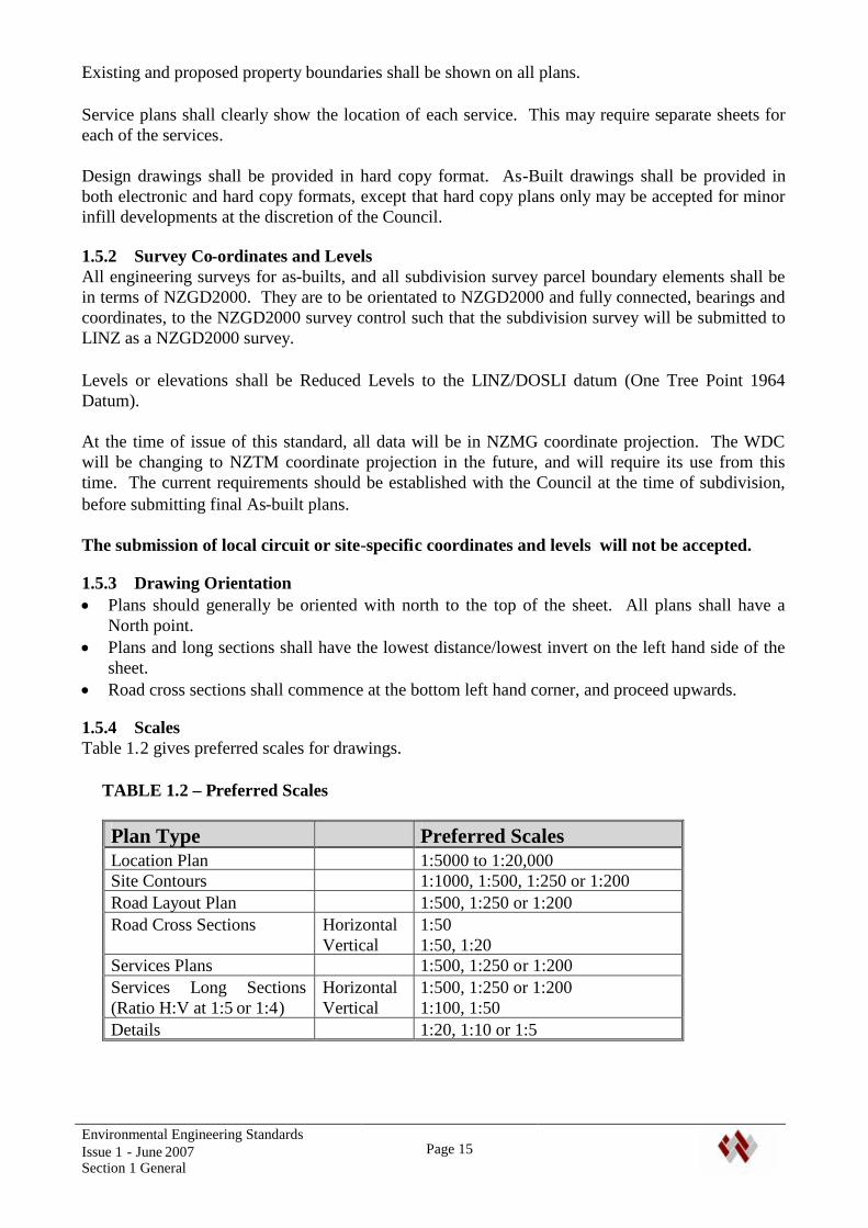
1.5.4 ScalesTable 1.2 gives preferred scales for drawings.
TABLE 1.2 – Preferred Scales
Plan Type Preferred ScalesLocation Plan 1:5000 to 1:20,000Site Contours 1:1000, 1:500, 1:250 or 1:200Road Layout Plan 1:500, 1:250 or 1:200Road Cross Sections Horizontal
Vertical1:501:50, 1:20
Services Plans 1:500, 1:250 or 1:200Services Long Sections(Ratio H:V at 1:5 or 1:4)
HorizontalVertical
1:500, 1:250 or 1:2001:100, 1:50
Details 1:20, 1:10 or 1:5
Environmental Engineering StandardsIssue 1 - June 2007Section 1 General
Page 16
1.5.5 Hard Copy FormatAll drawings shall be prepared on standard ISO A1, A2 or A3 drawing sheets, with a cleanbackground. Where A1 or A2 sheets are used, reduced A3 copies to scale shall also be provided.
Drawings must be suitable for photo reduction and microfilming. Lines shall not be finer than 0.25mm on A2 sheets and 0.35 mm on A1 sheets. Printing should be spaced sufficiently to retainclarity when reduced. Capital letters shall be not less than 2.5 mm in height before reduction fromA1 size. Where a mixture of capital and lower-case letters are used, the height shall be not less than3.5 mm on A1 sheets.
1.5.6 Electronic FormatsDrawing formats shall be: AutoCAD .dwg files, including all referenced files required. As-built plans to be a full set of all
plans, updated to include as-built information, easements etc, and, .pdf copies of drawings, endorsed/certified as as-built drawings.
DXF files may be accepted (subject to compatibility with WDC system).
Particular requirements for AutoCad drawings include: Layouts shall be set up so they may be printed as they are required to be printed, i.e. with all
necessary layers turned on and irrelevant information frozen. Layers that are required for thedesign but are not required to be printed shall have the ‘DO NOT PRINT’ symbol selected in thelayer control area,
All x-refs, pen assignments, images and special fonts used shall be included with the drawingfile,
Layouts shall be named to represent the content of each sheet (normally the sheet title), Different elements of the drawing shall be drawn on its own appropriately named layer, e.g.
sewer manholes on a ‘SWMH’ layer), As-Built layouts shall have ‘As-Built’ incorporated in the title, Layouts should have line-type scale setting inset into them to ensure correct printing.
1.5.7 Electronic Asset Information Data RequirementsIn addition to the above requirements, an Excel spreadsheet with As-Built asset information asdetailed in Appendix B shall be provided.
1.6 CONTENT OF DRAWINGSDrawings shall include:
General A locality plan of the site including major street names and other major features. The locality
plan shall include a north point. Legal descriptions of the site, and adjacent properties, The overall extent of the works, including the relationship with works or services adjacent to the
site. This includes clearly identifying existing works that will be modified, removed orabandoned.
Earthworks Earthworks drawings showing existing and proposed contours, areas of cut and fill, batter
slopes, drainage details, silt control measures etc.Roads and Access Design of roads, including plans, long and cross sections showing vertical and horizontal road
geometry,

Environmental Engineering StandardsIssue 1 - June 2007Section 1 General
Page 17
Pavement details, Kerbing and side drains, berms, footpaths, cycleways, etc, Road marking, signs and signals and all road furniture, Details of information signs shall include
the full layout, including sign text and colours, Proposed planting of berms. An electronic file of coordinates for road centrelines and edge of seal/kerblines, Details of accesses including berm crossings and drainage.General Services Location of services in berms and accessways in relation to other services and site boundaries,Stormwater A contour plan of the development site prior to any works commencing showing the location of
existing flow paths, and a contour plan of the developed site showing the proposed stormwaterworks and flow paths,
Plans and long sections of reticulation, showing the location of all sumps, manholes etc, pipelengths, sizes, materials, cover, levels and grades of stormwater drains. Location and depth ofservices that cross existing or proposed drains/pipes,
Plans, long sections and cross sections of all open drains and watercourses, Details of inlet/outlet structures including protective screens, Details of stormwater treatment/attenuation devices Floodplain / Secondary Flow Path levels and boundaries, and easement requirements.Wastewater Plans and long sections showing the depth and location of all pipelines including lengths, sizes,
materials, class of pipes, cover, levels and grades of wastewater reticulation. Location and depthof services that cross existing or proposed reticulation,
Depth, location, and details of all access structures, service connections etc, Details of connection into the existing reticulation and other special connections, Special details, including pump stations, rising mains, air valves, odour control facilities etc. The make and model of all pumps, valves and other equipment Pipeline details including thrust blocks, special connections, pipeline bridges etc.Water Supply The depth and location of all pipelines, including lengths, pressure class, sizes, materials and
cover. Location and depth of services that cross existing or proposed reticulation, Depth and location of service connections, valves, hydrants, bends, tees, meters, meter boxes,
backflow devices etc, Details of connection into existing reticulation and other special connections, Special details, including pump stations, reservoirs. Pipeline details including thrust blocks, pipeline bridges etc, The make and model of all pumps, valves and other equipment. Nominal static pressure at the connection point and at the lowest point in the works, design
pressure and maximum design pressure.Power, Telecommunications and Gas The depth and location of existing and proposed provision of power, telecommunications and
gas services. Lighting provisions.Reserves and Landscaping Details of proposed earthworks, landscaping, planting etc of reserve areas, including stormwater
and recreational reserves.
Environmental Engineering StandardsIssue 1 - June 2007Section 1 General
Page 18
1.7 AS-BUILT DRAWINGS, SCHEDULES OF ASSET INFORMATION ANDOPERATION AND MAINTENANCE MANUALS
1.7.1 General"As-Built" drawings, Schedules of Asset Information and Operation and Maintenance Manuals shallbe provided on completion of construction work as described below.
The requirements for As-Built drawings, Asset Information and O&M Manuals apply to theinstallation or modification of all Council assets, irrespective of whether they are worksassociated with a Resource Consent or otherwise.
For Developments:The 224c certificate for a development will not be issued until As-Built drawings, Schedules ofAsset Information and O&M Manuals have been provided and approved.
For Whangarei District Council Contracts:The Practical Completion Certificate will not be issued until As-Built drawings, Schedules ofAsset Information and O&M Manuals have been provided and approved.
1.7.2 As-Built DrawingsAs-Built drawings shall be provided in Hard Copy and Electronic formats, to the followingrequirements:
Drafting Standards shall be as detailed in Section 1.5 of this standard. Drawings that use aerialphotographs in the proposal drawings shall be provided without aerial photographs for the As-Built drawings.
Drawing Content shall include: All requirements of Section 1.6 of this standard. A full set of Construction drawings,
including all sheets submitted for the proposal updated to include As-Built information shallbe supplied. This shall include sheets that have not been amended since the application.This includes Index Sheets, Locality Plans, Earthworks, Long Sections, Cross Sections, Co-ordinate Sheets, Details etc,
As-built drawings shall include non-physical details such as the extent of overland flowpaths,
All further requirements of the As Built checklists in Appendix B. Specific requirements in the particular sections of this standard All drawings required by the statutory consent authorities in the consent application(s).
The As-Built drawings shall show what has actually been constructed, including all approvedchanges made during construction. Drawings shall label roads with WDC approved road names, andparcels with house numbers. The drawings shall also accurately locate the position and depth of allexisting services exposed during the construction.
Location and level data for both plans and asset schedules shall be to the co-ordinates and levelrequirements of Section 1.5.2, to the following accuracy:
Levels accurate to 10 mm, Locations accurate to 100 mm.
As built drawings shall be adequately labelled and dated. The developer’s representative shallcertify the accuracy of the information.

Environmental Engineering StandardsIssue 1 - June 2007Section 1 General
Page 19
1.7.3 Asset Information ScheduleAn Asset Information Schedule shall be provided in the format required in Appendix B. It shallconsist of a full inventory list of all Council assets that have been provided AND all assets that havebeen removed, The asset schedule shall be cross-referenced with the drawings using a simplesequential numbering system. Cross-reference numbers on as-built drawings shall be underlined todistinguish them from other numbers.
The Asset Information Schedule shall include: Component Type/Description Unit Type Installation Date Expected Life Location X,Y,Z Co-ordinates & inverts – for ‘point data’. – For lines, pipes and mains, co-
ordinates at the start, end, 20 m centres, change of material/size etc. shall be shown on plans, Material and class, Size, Quantity, Serial Number, Ground Surface description, Manufacturer.
1.7.4 Operation and Maintenance ManualsOperation and Maintenance Manuals shall be provided for all mechanical equipment orinstallations, including sewer pump stations, water supply booster pumps, actuated valves, treatmentfacilities , water quality treatment devices, attenuation structures and outlet controls, etc.
1.8 RAMM DATA REQUIREMENTSRAMM (Road Assessment and Maintenance Management) data is required as set out below for allroads or other assets such as car parks constructed or altered by applicants which are to bemaintained by Council. RAMM data requirements are as set out in Whangarei District CouncilRAMM data forms.
For Developments:The Whangarei District Council will use its RAMM Consultant to handle RAMM data capture forCouncil maintained road and parking assets on behalf of Council.
Developers are required to assist Council's Consultant by providing all information required for thiswork. This includes: All pavement details, including metal types, depths and sources of aggregate, Typical sections and plan views, Top surface and sealing data, Dates that each pavement layer, surfacing etc. are constructed, Details of subsurface drainage, geotextile layers, and all other buried features, Information on all structures, including bridges, retaining structures etc (Note that culverts with
a waterway area greater than 3.4 m2 are regarded as bridges under the TNZ bridge manual), Details of all road signs.
For roads, accessways and access lots serving 5 or more lots or dwelling units, which are intendedto be named but not maintained by Council, the applicant shall supply the carriageway length,width, road name and street name blade, pole and fixing/mounting data only.
Environmental Engineering StandardsIssue 1 - June 2007Section 1 General
Page 20
This information shall be available with the As-Built data above.
For Whangarei District Council Contracts:Requirements for obtaining RAMM data shall be as set out in the particular Contract Conditions.In general the Professional Services Consultant will be responsible for providing the RAMM data,with the Contractor assisting the Consultant with data capture.
RAMM data shall be presented using the Whangarei District Council Standard Forms, for: Carriageway, Pavement Layers, Traffic Facilities and Markings Signs, Drainage and Footpaths Crossings, features and minor structures.
RAMM data shall be provided to the requirements of the Council prior to the issue of the PracticalCompletion Certificate.
1.9 REGISTERED CONTRACTORS AND LICENSED CONTRACTORSFor some infrastructure services, the Whangarei District Council maintains a list of Contractors thatare permitted to construct or work on Council Assets. Contractors on such a list may be eitherRegistered or Licensed Contractors.
Registered Contractors are Contractors that demonstrate to Council that they have the resources andcompetence to carry out the type of work, that they have acceptable Health and Safety andmanagement systems, and that they comply with all other requirements of the Council (e.g.insurances etc).
Licensed Contractors are generally a limited number of specialist contractors that the Council hasapproved to perform particular types of work (e.g. live connections to Water reticulation). Suchwork shall only be carried out by Licensed Contractors.
Where the Council maintains a list of Registered or Licensed Contractors for a particular type ofwork, only Registered or Licensed Contractors (as applicable) may carry out such work on Councilassets or assets that will be transferred to Council ownership.
The Council Policy on Registered and Licensed Contractors, and the current list of Licensedcontractors is available from the Council.
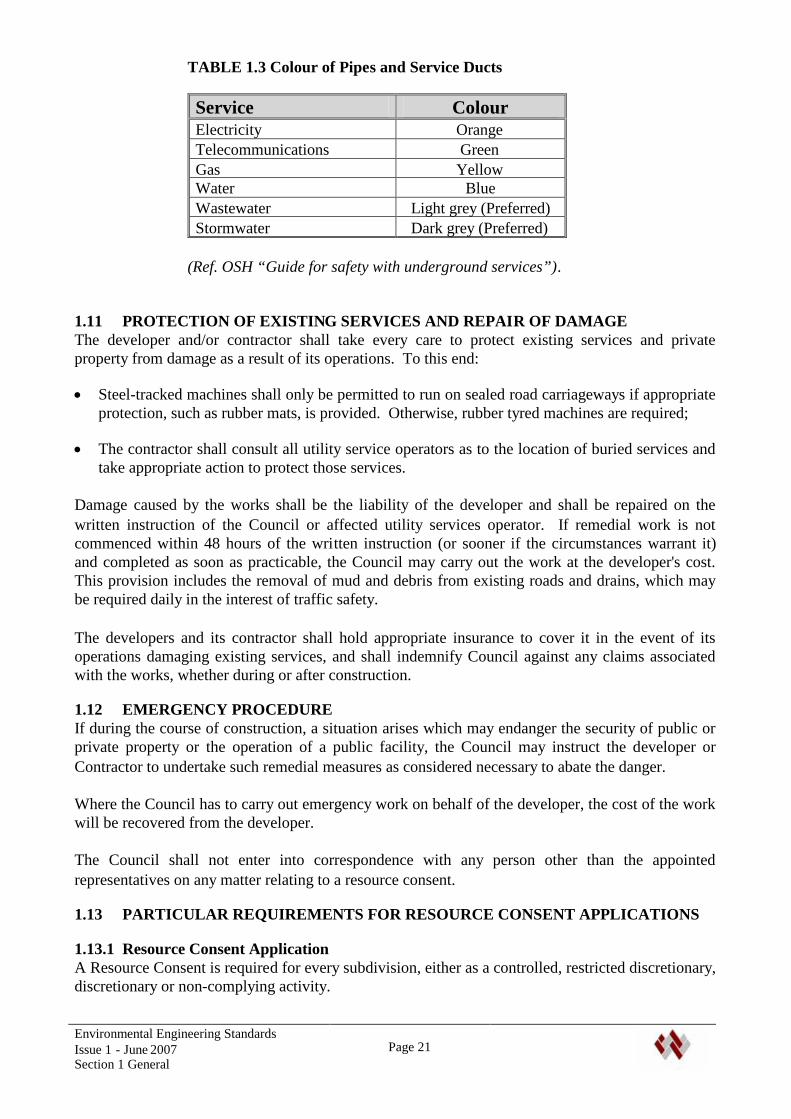
1.10 COLOUR OF PIPES AND DUCTSPipelines and ducts installed shall comply with the requirements of the utility service providers. Inorder to identify in-ground services, pipes with the colours in Table 1.3 shall be used where possiblefor the relevant services. Other services shall not use pipes with these colours (including the colourof stripes on pipes). Note also particular requirements for detection tapes identifying Councilservices.
The internal colour of wastewater and stormwater pipes shall be suitable for video inspection(normally black will not be approved).
Environmental Engineering StandardsIssue 1 - June 2007Section 1 General
Page 21
TABLE 1.3 Colour of Pipes and Service Ducts
Service ColourElectricity OrangeTelecommunications GreenGas YellowWater BlueWastewater Light grey (Preferred)Stormwater Dark grey (Preferred)
(Ref. OSH “Guide for safety with underground services”).
1.11 PROTECTION OF EXISTING SERVICES AND REPAIR OF DAMAGEThe developer and/or contractor shall take every care to protect existing services and privateproperty from damage as a result of its operations. To this end:
Steel-tracked machines shall only be permitted to run on sealed road carriageways if appropriateprotection, such as rubber mats, is provided. Otherwise, rubber tyred machines are required;
The contractor shall consult all utility service operators as to the location of buried services andtake appropriate action to protect those services.
Damage caused by the works shall be the liability of the developer and shall be repaired on thewritten instruction of the Council or affected utility services operator. If remedial work is notcommenced within 48 hours of the written instruction (or sooner if the circumstances warrant it)and completed as soon as practicable, the Council may carry out the work at the developer's cost.This provision includes the removal of mud and debris from existing roads and drains, which maybe required daily in the interest of traffic safety.
The developers and its contractor shall hold appropriate insurance to cover it in the event of itsoperations damaging existing services, and shall indemnify Council against any claims associatedwith the works, whether during or after construction.
1.12 EMERGENCY PROCEDUREIf during the course of construction, a situation arises which may endanger the security of public orprivate property or the operation of a public facility, the Council may instruct the developer orContractor to undertake such remedial measures as considered necessary to abate the danger.
Where the Council has to carry out emergency work on behalf of the developer, the cost of the workwill be recovered from the developer.
The Council shall not enter into correspondence with any person other than the appointedrepresentatives on any matter relating to a resource consent.
1.13 PARTICULAR REQUIREMENTS FOR RESOURCE CONSENT APPLICATIONS
1.13.1 Resource Consent ApplicationA Resource Consent is required for every subdivision, either as a controlled, restricted discretionary,discretionary or non-complying activity.

Environmental Engineering StandardsIssue 1 - June 2007Section 1 General
Page 22
Reference to the Whangarei District Plan is required to establish requirements for a ResourceConsent Application.
An ‘Application Pack’ for Resource Consents – Subdivision is available from the WhangareiDistrict Council, or from the Council web-site (www.wdc.govt.nz). The Application Pack contains:
Guides to assist in applying for a Resource Consent, Application Forms.
The Guide and Application Forms identify information requirements for the Application.
A formal application under the Resource Management Act must be made where a variation tostandards in the District Plan or resource consent conditions is proposed. Where a developer wishesto take advantage of any discretion referred to in these standards, it must be specifically identified inthe application.
1.13.2 Developer's RepresentativeThe developer shall nominate a specialist representative to liaise with the Council. The developer'srepresentative would generally be a Registered Surveyor, Resource Management/PlanningConsultant or Chartered Professional Engineer, but may be a suitably qualified person in a relatedfield, experienced in all phases of resource consent. The representative shall be available for sitevisits within 24 hours of being so requested by the Council.
The Representative shall provide, or arrange for suitably qualified and experienced persons toprovide the following: Surveying and engineering reports, design, documentation and drawings. This may include the
design and control of earthworks and assessment of site suitability including land stability,hazards etc. to be evaluated under the District Plan.
Supervision of the works required by the approved engineering drawings and specifications. Certification that the works and authorised variations have been carried out in accordance with
the approved documents and sound engineering practice. Preparation, certification and submission of "As-built" drawings of the completed works.
1.13.3 Fees and ChargesThe applicant shall pay all fees and charges relating to the assessment of the application, review andapproval of drawings and documents, inspections carried out, legal fees in connection with drainageeasements, bonds, etc., and such other fees and charges where applicable.
Engineering plan inspection fees are to be paid prior to plan approval.
1.13.4 Cost of the Work and Council ContributionsThe developer is responsible for all costs associated with the application and all construction workrequired. This includes provision and relocation of services, connections to existing services, andall other permanent or temporary work required for the development. It may also involve upgradingexisting infrastructure required because of the effects of the development.
The developer shall pay all development contributions and other charges set by the Council.
The applicant should liaise with appropriate utility service operators prior to submitting a ResourceConsent application to establish any additional requirements or costs.

Environmental Engineering StandardsIssue 1 - June 2007Section 1 General
Page 23
In special circumstances, Council may contribute towards the cost of work in terms of an applicablepolicy, or as negotiated. Generally such contributions would cover the provision of services greaterthan required for the immediate proposal. The basis and timing of payment are subject tonegotiation with Council. All such agreements shall be confirmed in writing prior to commencingwork.
1.13.5 Approval by CouncilUpon the granting of a resource consent, the engineering services shall be designed by an approvedProfessional (Refer Section 1.4). Three sets of engineering construction drawings and one set ofspecifications, calculations and other relevant supporting information shall be supplied to theCouncil.
The Council will review the engineering drawings, specifications, design calculations and reports.If the documentation is not acceptable, Council will return one set of drawings with Councilcomments. (Note - if preferred, Council will examine and comment on one set of documents andwill receive the additional copies of the drawings for endorsement).
The developer shall revise the application as required and resubmit it to Council for endorsement.Such endorsement shall not relieve the developer of the responsibility to achieve the requirementsof this standard and the District Plan.
Where a drawing is approved that either by omission or error does not comply with theseStandards, the Council will require that the Standards are achieved.
Endorsement of drawings is subject to the payment of plan inspection fees.
The developer shall hold an endorsed copy of plans on site at all times during construction ofthe works.
1.13.6 Commencement of WorkNo work associated with a resource consent shall commence until;
The Council has granted the resource consent. All other statutory provisions have been met. (e.g. permit to disturb archaeological sites,
building consents obtained etc.) The requirements of the approval, including engineering drawings, specifications, design
calculations and reports for the work have been satisfied, and necessary fees paid. Any Council contribution toward the cost of work has been approved.
Any works undertaken prior to the final approval of engineering plans will be at the developers risk.The WDC reserves the right to reject such work, or request that the works to be opened up and / ortested for compliance / suitability.
The developers representative shall give the Council 24 hours notice of the intention to commenceconstruction work.
The developer shall advise Council in writing the name, address and contact details of allcontractors that will be carrying out work on the development or subdivision.

Environmental Engineering StandardsIssue 1 - June 2007Section 1 General
Page 24
1.13.7 Variations to Approved Engineering DocumentationWhere changes to the approved Engineering Documentation are required, the developer shall applyto the Council for approval of the change, and where required a Variation to the Consent.
The application shall include a statement on the effect of the variation on the original resourceconsent and documentation to support the need of a consent variation as a result. Such variationswill be processed in the same way as new works. Work shall not proceed until the Council grantsapproval to the variation.
1.13.8 Inspection of the work
1.13.8.1 Site InspectionsThe developer’s representative shall notify the Council 24 hours prior to requiring site inspections,which are necessary at the following stages of the work:
Completed earthworks and prepared subgrade, Verification of as-built drawings on-site prior to backfilling piped services and similar, Finished basecourse prior to the commencement of sealing, Prior to pouring any concrete, On completion of any service disconnections prior to backfilling, At all testing required by this Standard, including those noted below, At completion of all works when as-built drawings have been submitted and the site left neat
and tidy.
1.13.8.2 TestingInspection/Testing shall include:
Material testing, Fill compaction testing, CBR testing of road subgrade, Nuclear Densometer testing of road formation compaction, Clegg Hammer testing of Pavement, Pressure testing of pipelines, PE Pipe welding testing, including:
Calibration Certificate/Welders Registration, Joint tensile testing, Welding data-log records,
Video inspection of all wastewater and stormwater pipelines, Disinfection testing of water mains, Hydrant flow testing, Tracer Cable/Detection Tape testing, Testing of manholes and other pipeline components, Other testing as directed by the Council, including Benkelman Beam tests.
The developer shall pre-test the work and prove it satisfactory before requesting an inspection byCouncil to observe the testing and approve the work. Work shall not proceed until Council’sRepresentative has inspected the work, observed the required testing and approved the work, orCouncil has given written approval to proceed.

Environmental Engineering StandardsIssue 1 - June 2007Section 1 General
Page 25
1.13.9 Connection to Existing Services(Refer to Whangarei District Council forms WA, WWA and SWA)
The developer shall notify the intention to connect to Council owned services following successfultesting of the reticulation. Following approval to connect the developer shall arrange for theconnection to be made. For services where Council operates a Licensed Contractor system,connection shall only be made by a Licensed Contractor.
An authorised Council Officer/agent shall inspect connections prior to backfilling.
Where a connection is to be made within private property not owned by the developer, it is thedevelopers responsibility to obtain the approval, and make all necessary arrangements with theproperty owner concerned. Evidence of that owner's approval will be required by the Council.
1.13.10 As - Built Drawings, Asset Information Schedules and O&M ManualsAs-Built Drawings, Asset Information Schedules and Operation and Maintenance Manuals shall beprovided in compliance with Sections 1.6, 1.7 and 1.8 of this Standard.
The issuing of a 224 (c) certificate or release of a performance bond may be withheld if these are notprepared to the requirements of Council.
In the event of a service, including service connection, either not being provided although shown onthe "As-built" drawings, or not in the position shown, the developer's representative shall provide orlocate the service or, in the event that the service doesn’t comply with these standards or theapproved drawings, rectify the incorrect components. The Council shall then be provided withrevised “As-Built” drawings as necessary.
1.13.11 CompletionOn completion of the works, the developer shall provide the following: Geotechnical Reports and plans, All limitations on development of the properties, including hazards, easment requirements etc, As-built plans, Results of all testing, Video inspection records of all wastewater and stormwater reticulation, PE pipeline welding data logging results, Evidence that all infrastructure work has been completed to the requirements of the network
utility operator, including all requirements for final completion (refer requirements in Section1.13.13 below),
Design Certificates, Completion certificates, Operation and Maintenance manuals required by the Council RAMM information for public roading assets, All Consent Notices have been registered against property titles, Bonds in terms of Section 1.13.15 are in place.
1.13.12 Defects Liability PeriodThe Developer shall be responsible for the performance of all works provided by the developer thatwill become Council assets, for a minimum defects liability period as follows:
Environmental Engineering StandardsIssue 1 - June 2007Section 1 General
Page 26
12 months for roads and landscape planting, Where roading involves a second coat seal, thedefects liability period for the sealing shall be for a period of not less than 2 months after theapplication of the second coat seal.
12 months for other services. The Council may require a maintenance period of 3 to 5 years as a condition of a Resource
Consent for plant maintenance, and weed/pest control.
The defects liability period shall commence from the date that the final inspection is approved, orthe date the resource consent completion or conditions certificate is issued, whichever is the latter.
1.13.13 Requirements for Final CompletionPrior to final acceptance at completion of the maintenance period, the developer shall satisfy thefollowing requirements:
Berm grass to be mown. Carriageways and footpaths swept. All sumps and piped disposal systems cleaned out. Planted areas to be left in a state suitable for ongoing maintenance – including:
- All plants healthy- Depths of mulch as specified in plans- Grass established- Removal of all weeds and noxious vegetation from berms, reserves etc
Any outstanding maintenance items completed Written approval from other utility service operators as necessary
1.13.14 InsurancesWhere work is to be carried out on a dedicated road or reserve, or on a Council asset, the developershall ensure that the following insurance is in place prior to commencing work:
Public Liability Insurance in the name of the developer for an amount of $ 2,000,000. Fordevelopments where the value of work on public land or Council asset is low, Council mayreduce the required value of the public liability insurance to relate to the risk, but not less than150% of the value of this work. The Policy shall cover all insurable risks normally applicable toland development work until the end of the maintenance period. Such risks may includeflooding due to burst water mains, property damage due to land slips or contamination of naturalwater due to overflowing sewerage reticulation.
The developer’s representative and IQPs shall hold current professional indemnity insurancewith minimum cover of $200,000.
The developer shall indemnify Council against any claims arising from insurable risks until theend of the maintenance period.
The developer shall ensure that its contractors also hold insurance cover appropriate to theserequirements. The developer shall provide evidence of insurance cover prior to the commencementof the work.
1.13.15 BondsBonds may be required in terms of Councils Resource Consent Operational Policies forMaintenance Work or Uncompleted Work.
General conditions relating to bonds are summarised as follows. The relevant policies shall beconsulted to establish the full conditions:
Environmental Engineering StandardsIssue 1 - June 2007Section 1 General
Page 27
Generally only minor uncompleted works and where approved, carriageway sealing may bebonded. Critical infrastructure (e.g. road formation, water, wastewater, stormwater, powersupply etc.) will not normally be bonded.
The bond shall be an agreed cash deposit, or a bank bond from a New Zealand based TradingBank
No interest will be paid on bond monies, For physical work, the amount of the bond shall be 150% of the estimated value of the intended
bonded engineering work, or as otherwise approved, For maintenance the amount of the bond shall be 5% of the estimated value of the intended
bonded engineering work, , or as otherwise approved, The developer is responsible for providing all necessary documentation, The developer shall pay all processing fees, legal costs and disbursements relating to the bond, The bond may be registered against the title of the property.
1.13.15.1 Performance BondPerformance Bonds may be required to ensure the performance, completion and/or maintenance ofcertain works under the Resource Management Act 1991. Performance bonds may be made acondition of consent in accordance with the applicable Resource Consent Operational Policy.
Performance Bonds may be applied if: Non-completion has the potential to result in adverse effects outside of the subject site boundary
or expose council to possible financial and/or litigation claims, Work is to be undertaken on Council owned/administered land, A maintenance period is required on assets to be vested to Council, It is unreasonable to delay the issuing of 224 (c) certificate due to conditions of consent relating
to planting/control, It is unreasonable to delay the issuing of 224 (c) certificate due to conditions of consent that
cannot reasonably be completed by this stage, and which may result in adverse effects outside ofthe subject sites boundary.
The term of the bond shall be appropriate to the extent and scope of the consent condition, and inaccordance with accepted industry practice.
The bond will be released on completion of all works, acceptance at the end of the maintenanceperiod, and on payment of any applicable fees.
1.13.15.2 Uncompleted Works BondUncompleted Works Bonds may be implemented to enable short-term deferral of certain physicalworks under the Resource Management Act 1991. Such bonds shall only be entered into if theapplication complies with the specific requirements of the applicable Resource Consent OperationalPolicy.
The main requirements are summarised below: Bonds are for engineering works required by conditions of an approved resource consent, Delayed implementation shall not result in adverse effects outside the boundary, prevent
vehicular access to each lot from a road, inhibit occupation of lots for their proposed land use, orresult in, or leave a hazard to public safety.
The term of the bond shall not exceed 12 months

Environmental Engineering StandardsIssue 1 - June 2007Section 1 General
Page 28
Where compliance with the conditions of resource consent is issued under bond, the balance of theconstruction work outstanding shall be completed within the term of the bond.The bond for outstanding work is refundable upon confirmation of final inspection and acceptanceby the Council following completion of the works, payment of all associated fees, and submissionof a maintenance bond where appropriate.
The maintenance period for the work shall commence at the completion of the whole of the work,except as otherwise permitted.
Environmental Engineering StandardsIssue 1 – June 2007Section 2 Site Suitability and Earthworks
Page 29
2. SITE SUITABILITY AND EARTHWORKS
2.1 GENERAL REQUIREMENTS
2.1.1 GeneralThis Section covers the requirements for the following: Assessment of land stability and suitability for the proposed use, Design and control of earthworks, Assessment of ground suitability for the construction of roads, buildings etc, Assessment of other hazards that may affect the development. This may include hazards
identified in the District Plan or in Council Reports, or hazards identified as part of the siteinvestigation.
2.2 REFERENCED DOCUMENTS
The following documents shall be read in conjunction with this section of these standards: Whangarei District Plan (WDC) Regional Soil and Water Plan for Northland (NRC) Regional Coastal Plan for Northland (NRC) NZS 4431:1989 Code of Practice for Earth Fill for Residential Development, WDC Coastal Structure Plan – Slope instability Potential and Effluent Disposal Potential,
Oakura to Langs Beach. Stormwater Catchment Management Plans Coastal Hazard and Erosion Studies (WDC/Jeremy Gibbs)
The above documents will be added to from time to time as further investigations and reports arecompleted. The applicant is advised to obtain information from Council on any relevant documentsapplicable to the site.
The Council has copies of investigations carried out to support development proposals across theDistrict. Reports on adjacent sites may be available, subject to limitations on their use.
2.2 TECHNICAL REQUIREMENTS
2.2.1 Preliminary Site EvaluationThe applicant shall obtain information available from the Council and other sources on hazards anddevelopment limitations that may affect the development.
Hazards identified by Council include: Coastal Erosion and Instability, Earth Movements Mine Zones, Flood Zones
Information on these hazards is available via the District Plan, the WDC GIS, or specificinvestigations/reports.
Environmental Engineering StandardsIssue 1 – June 2007Section 2 Site Suitability and Earthworks
Page 30
The applicant shall engage a geotechnical engineer to carry out a preliminary site evaluation andprepare a geotechnical assessment report, except where the applicant can otherwise demonstrate thatthe site is stable and suitable for the proposed use, and the proposed earthworks on the site areminor in scale.
An IQP shall carry out an evaluation as required on other hazards.
2.2.2 Coastal AreasMinimum site levels in coastal areas shall take into account storm surge, tsunami hazards, erosionpotential, climate change and sea level rise. The minimum floor level where there are no particularhazards should normally be RL 3.0, with an absolute minimum of RL 2.5. The level of the generalsite, parking areas and access roads shall provide for emergency access and use. These shouldnormally have a minimum level of RL 2.5.
Specific investigation and design shall be carried out where there are particular hazards.
2.2.3 Geotechnical Assessment ReportThe geological/geomorphological assessment should entail most or all of the following steps, and abrief report should specifically address the expected effects of the subdivisional and/or buildingdevelopment on the land.
The following risk levels are identified in WDC reports on slope stability. Where the site is outsideof an area covered by such reports, an assessment shall be made by a geotechnical engineer as towhich level is appropriate.
Low Risk LandThe geotechnical assessment of low risk land would be expected to include: Walk-over inspection of the site and the surrounding land Inspection of aerial photographs taken at various times to provide insight into the local
geomorphology and evidence of any previous instability Review of geological data (maps, bulletins) Enquiry after local information about stability/instability of the ground Seek existing data about the soil and rock profile (look for nearby exposures) or perform some
simple subsurface investigation Examination of the soil profile to confirm that if the soil is in-situ and not colluvium (slide
debris) Examination of the existing survey records for evidence of movement (slippage or erosion) An opinion stated by a geotechnical specialist as to the stability of the land for development
(including an assessment of the effects of development such as excavation, filling, removal ofvegetation, disposal of stormwater or effluent wastewater into or over the area).
Moderate stability hazardA geotechnical assessment on moderate risk land would be expected to include: Topographic survey (if not already available) or slope profiles. A description of the geology and geomorphology of the area, including comment on the areas
surrounding the development site. Definition of the nature and continuity of the strata over the whole area of land which is
proposed to be developed (buildings, access and services) and to a depth below which slippingis most unlikely, by means of test pit and/or drilling and/or augering (unless existing exposuresare adequate).
Environmental Engineering StandardsIssue 1 – June 2007Section 2 Site Suitability and Earthworks
Page 31
Assessment of the relative strength and the sensitivity of the soil in each stratum in which, orinterface on which, sliding is possible.
Assessment of likely groundwater levels and piezometric pressures in the strata during extremeinfiltration conditions.
An opinion stated by a geotechnical specialist as to the stability and suitability of the land fordevelopment. The stability of the whole slope (upon which the site may only form a part of) andthe effects of the development (such as excavation, filling, removal of vegetation, disposal ofstormwater or effluent waste water into or over the area) on this should be given.
High stability hazardA geotechnical report on high landslip hazard areas land would be expected to include: Topographic Survey (if not already available) A description of the geology and geomorphology of the area and immediate surrounding areas. Definition of the nature and continuity of the strata over the whole area of land involved, and to
a depth below which slipping is most likely, by means of test pits and/or continuous recoverycore drilling (unless existing exposures are adequate).
Determination of the peak and residual shear strength parameters (either from laboratory tests orback analysis of relevant slope failures) and the sensitivity of the soil in each stratum in which,or interface on which, sliding is possible.
Assessment of groundwater levels and piezometric pressures in the strata during extremeinfiltration conditions.
Analysis of possible failure mechanisms, relevant to the specific geology and geomorphology ofthe site using effective stresses.
An opinion stated by a geotechnical specialist as to the stability of the ground and thepreventative (or remedial) measures to be incorporated in the development.
The stability of the whole slope (upon which the development site may form only part of) andthe effects of the development (such as excavation, filling, removal of vegetation, disposal ofstormwater or effluent waste water into or over the area) on this should be given.
2.2.4 Stabilisation WorksWorks may be required to protect or restore the land. These may include earthworks (to reduceslope angles or place buttress fills), drainage works (trench drains, buttress or counterfort drainsaligned down the true slope angle are particularly effective), retaining structures, erosion protectionstructures, and planting.
Where a site requires works to ensure stability of a landform, such works shall be carried out as partof the subdivision or development.
2.2.5 Restrictions on DevelopmentWhere a suitability report recommends restrictions be applied to specific areas of a landdevelopment proposal, a plan defining those areas will be required to accompany the report. Anyrestrictions on development contained in the suitability report must be presented in tabular formwith definite conclusions and recommendations to enable the report to be easily interpreted.
Reports will be used as the basis of a Consent Notice to be registered against the title of the landaffected. Such reports are required prior to any resource consent being issued. (See WhangareiDistrict Council Forms A, B and C.)
2.3 LANDFORMThe developed landform shall preserve natural features as much as practicable, including theretention of natural watercourses.
Environmental Engineering StandardsIssue 1 – June 2007Section 2 Site Suitability and Earthworks
Page 32
2.4 COMPACTION OF FILL MATERIALCompaction of fill material shall be as set out in NZS 4431, or as specified by the geotechnicalengineer where NZS 4431 is not applicable.
2.5 EROSION, SEDIMENT AND DUST CONTROLLand disturbance activities shall comply with the ‘Environmental Standards for Land DisturbanceActivities’ in the NRC Regional Water and Soil Plan for Northland.
This will require detention ponds, silt fences etc. The use of flocculants may be required in surfacewater sediment control ponds depending on the sensitivity of the location and receivingenvironment.
All consents required for Land Disturbance activities shall be obtained from the Northland RegionalCouncil.
Control of dust shall be considered in the planning and design of a project.
2.6 REPORT ON COMPLETION OF CONSTRUCTION
Where excavation or filling has been carried out, a report identifying the extent of the work and theinspection and test results shall be submitted on completion of construction and prior to the finalinspection of the development. This shall be accompanied by a statement of professional opinion asto the compliance of the filled ground to the specification and the suitability of the area fordevelopment. (See Whangarei Distrct Council Forms A, B and C.)

Environmental Engineering StandardsIssue 1 – June 2007Section 3 Roads and Access
Page 33
3. ROADS AND ACCESS
3.1 GENERAL REQUIREMENTS
3.1.1 GeneralThis Section covers the requirements for the design and construction of roads associated with landdevelopment.
The objective is to provide safe roads with appropriate operating speeds, and provide for utilityservices and environmental considerations.
3.1.2 Scope of DesignRoad design shall provide for the various components of a road as follows: Road carriageway, bridges, culverts etc, Pedestrian and cycle facilities, Road lighting, Road marking and signs, (including name signs for public and private roads). Berm and amenity provisions, Vehicle parking and manoeuvring areas, Utility services, Stormwater control, including stormwater treatment and ‘low-impact’ design structures, Use as secondary flow paths for stormwater.
Roads shall include provision for future development outside of the property boundary, and impactson the surrounding road network.
3.2 REFERENCED DOCUMENTSThe following documents shall be read in conjunction with this section of these standards: Whangarei District Plan (WDC) WDC Working Within Road Reserves Policy and Specification WDC Road Opening Notice WDC Road Naming Policy (April 2005) WDC RAMM data forms. Transit New Zealand (TNZ) Manuals and Technical Documents, as listed in the TNZ Standards,
Criteria and Guidelines Manual, including: AS/NZS Standards, - (AS/NZS 1158 Road Lighting), TNZ Code of Practice - Temporary Traffic Management Austroads Rural Road Design Austroads Urban Road Design Austroads Pavement Design, including NZ Supplement, Austroads Pavement Design for Light Traffic (a supplement to Austroads Pavement Design
Guide) Austroads Guides to Traffic Engineering Practice TNZ State Highway Geometric Design Manual TNZ/LTSA – Manual of Traffic Signs and Markings (MOTSAM), TNZ Bridge Manual, Austroads Waterway Design. TNZ New Zealand Supplement to Austroads Guide Part 14: Bicycles

Environmental Engineering StandardsIssue 1 – June 2007Section 3 Roads and Access
Page 34
TNZ /Transfund Specifications and Notes for Road Construction, Maintenance and MaterialStandards,
LTSA Guidelines (RTS series) and Manuals, NZ Institute of Highway Technology approved Pavement Design Techniques, NZ Transport Strategy. Auckland Regional Council Technical Publication 10 (ARC TP 10) - Stormwater Treatment
Devices Design Manual
Where aspects of the design are not covered by this section or the above documents, the followingstandards may be referenced. Adoption of any practises outside of the Council documentation mustfirst be approved by the Roading Manager.
NZS 4404:2004 Land Development and Subdivision Engineering, New Zealand Building Code (NZBC).
The most up to date of these publications shall supersede any conflicting requirements of olderdocuments.
3.3 SUBMISSION OF APPLICATION
3.3.1 Supporting Information and CalculationsThe design shall include site investigations, supporting information and calculations to demonstratecompliance with the design requirements. This shall include: Testing of the pavement subgrade, Assessment of traffic volumes Pavement design, Surfacing Design Design of surface drainage and other road components, Utility service locations.
The design shall be carried out by a qualified Professional, who shall provide a design certificateidentifying the design standards used, and certifying that the design complies with these standards.Where required by the Roading Manager, the design and certification shall be carried out by an IQP.
3.3.2 Design Drawings and SpecificationsDesign drawings complying with the requirements of Sections 1.5 and 1.6 shall be provided forapproval.
3.3.3 Approval of DesignThe drawings and calculations will be reviewed by the Roading Manager or his/her representative.The completed form and the drawings showing any alterations shall be returned to the applicant’srepresentative. If adjustments to the design are required a new set of amended drawings shall besubmitted to the Council prior to approval being granted. Only drawings stamped and signed by theRoading Manager shall be deemed approved drawings. Unless specifically stated otherwise, theapproval of drawings does not supersede the requirements or obligations of these standards.
3.4 DESIGN REQUIREMENTS
Road standards shall comply with Tables 3.1 to 3.5.
Environmental Engineering StandardsIssue 1 – June 2007Section 3 Roads and Access
Page 35
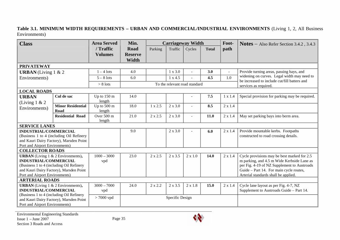
Table 3.1. MINIMUM WIDTH REQUIREMENTS – URBAN AND COMMERCIAL/INDUSTRIAL ENVIRONMENTS (Living 1, 2, All BusinessEnvironments)
Carriageway WidthClass Area Served/ TrafficVolumes
Min.Road
ReserveWidth
Parking Traffic Cycles TotalFoot-path
Notes – Also Refer Section 3.4.2 , 3.4.3
PRIVATEWAY1 – 4 lots 4.0 1 x 3.0 - 3.0 -5 – 8 lots 6.0 1 x 4.5 - 4.5 1.0
URBAN (Living 1 & 2Environments)
> 8 lots To the relevant road standard
Provide turning areas, passing bays, andwidening on curves. Legal width may need tobe increased to include cut/fill batters andservices as required.
LOCAL ROADSCul de sac Up to 150 m
length14.0 - 7.5 1 x 1.4 Special provision for parking may be required.
Minor ResidentialRoad
Up to 500 mlength
18.0 1 x 2.5 2 x 3.0 - 8.5 2 x 1.4
URBAN(Living 1 & 2Environments)
Residential Road Over 500 mlength
21.0 2 x 2.5 2 x 3.0 - 11.0 2 x 1.4 May set parking bays into berm area.
SERVICE LANESINDUSTRIAL/COMMERCIAL(Business 1 to 4 (including Oil Refineryand Kauri Dairy Factory), Marsden PointPort and Airport Environments)
9.0 2 x 3.0 - 6.0 2 x 1.4 Provide mountable kerbs. Footpathsconstructed to road crossing details.
COLLECTOR ROADSURBAN (Living 1 & 2 Environments),INDUSTRIAL/COMMERCIAL(Business 1 to 4 (including Oil Refineryand Kauri Dairy Factory), Marsden PointPort and Airport Environments)
1000 – 3000vpd
23.0 2 x 2.5 2 x 3.5 2 x 1.0 14.0 2 x 1.4 Cycle provisions may be best marked for 2.5m parking, and 4.5 m Wide Kerbside Lane asper Fig. 4-19 of NZ Supplement to AustroadsGuide – Part 14. For main cycle routes,Arterial standards shall be applied.
ARTERIAL ROADS3000 – 7000
vpd24.0 2 x 2.2 2 x 3.5 2 x 1.8 15.0 2 x 1.4 Cycle lane layout as per Fig. 4-7, NZ
Supplement to Austroads Guide – Part 14.URBAN (Living 1 & 2 Environments),INDUSTRIAL/COMMERCIAL(Business 1 to 4 (including Oil Refineryand Kauri Dairy Factory), Marsden PointPort and Airport Environments)
> 7000 vpd Specific Design
Environmental Engineering StandardsIssue 1 – June 2007Section 3 Roads and Access
Page 36
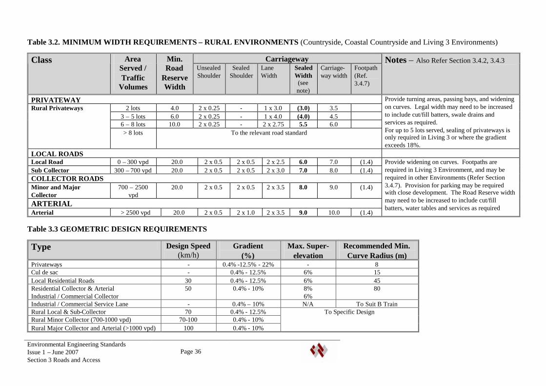
Table 3.2. MINIMUM WIDTH REQUIREMENTS – RURAL ENVIRONMENTS (Countryside, Coastal Countryside and Living 3 Environments)
CarriagewayClass AreaServed /Traffic
Volumes
Min.Road
ReserveWidth
UnsealedShoulder
SealedShoulder
LaneWidth
SealedWidth
(seenote)
Carriage-way width
Footpath(Ref.3.4.7)
Notes – Also Refer Section 3.4.2, 3.4.3
PRIVATEWAY2 lots 4.0 2 x 0.25 - 1 x 3.0 (3.0) 3.5
3 – 5 lots 6.0 2 x 0.25 - 1 x 4.0 (4.0) 4.56 – 8 lots 10.0 2 x 0.25 - 2 x 2.75 5.5 6.0
Rural Privateways
> 8 lots To the relevant road standard
Provide turning areas, passing bays, and wideningon curves. Legal width may need to be increasedto include cut/fill batters, swale drains andservices as required.For up to 5 lots served, sealing of privateways isonly required in Living 3 or where the gradientexceeds 18%.
LOCAL ROADSLocal Road 0 – 300 vpd 20.0 2 x 0.5 2 x 0.5 2 x 2.5 6.0 7.0 (1.4)Sub Collector 300 – 700 vpd 20.0 2 x 0.5 2 x 0.5 2 x 3.0 7.0 8.0 (1.4)COLLECTOR ROADSMinor and MajorCollector
700 – 2500vpd
20.0 2 x 0.5 2 x 0.5 2 x 3.5 8.0 9.0 (1.4)
ARTERIALArterial > 2500 vpd 20.0 2 x 0.5 2 x 1.0 2 x 3.5 9.0 10.0 (1.4)
Provide widening on curves. Footpaths arerequired in Living 3 Environment, and may berequired in other Environments (Refer Section3.4.7). Provision for parking may be requiredwith close development. The Road Reserve widthmay need to be increased to include cut/fillbatters, water tables and services as required
Table 3.3 GEOMETRIC DESIGN REQUIREMENTS
Type Design Speed(km/h)
Gradient(%)
Max. Super-elevation
Recommended Min.Curve Radius (m)
Privateways - 0.4% -12.5% - 22% - 8Cul de sac - 0.4% - 12.5% 6% 15Local Residential Roads 30 0.4% - 12.5% 6% 45Residential Collector & ArterialIndustrial / Commercial Collector
50 0.4% - 10% 8%6%
80
Industrial / Commercial Service Lane - 0.4% – 10% N/A To Suit B TrainRural Local & Sub-Collector 70 0.4% - 12.5%Rural Minor Collector (700-1000 vpd) 70-100 0.4% - 10%Rural Major Collector and Arterial (>1000 vpd) 100 0.4% - 10%
To Specific Design
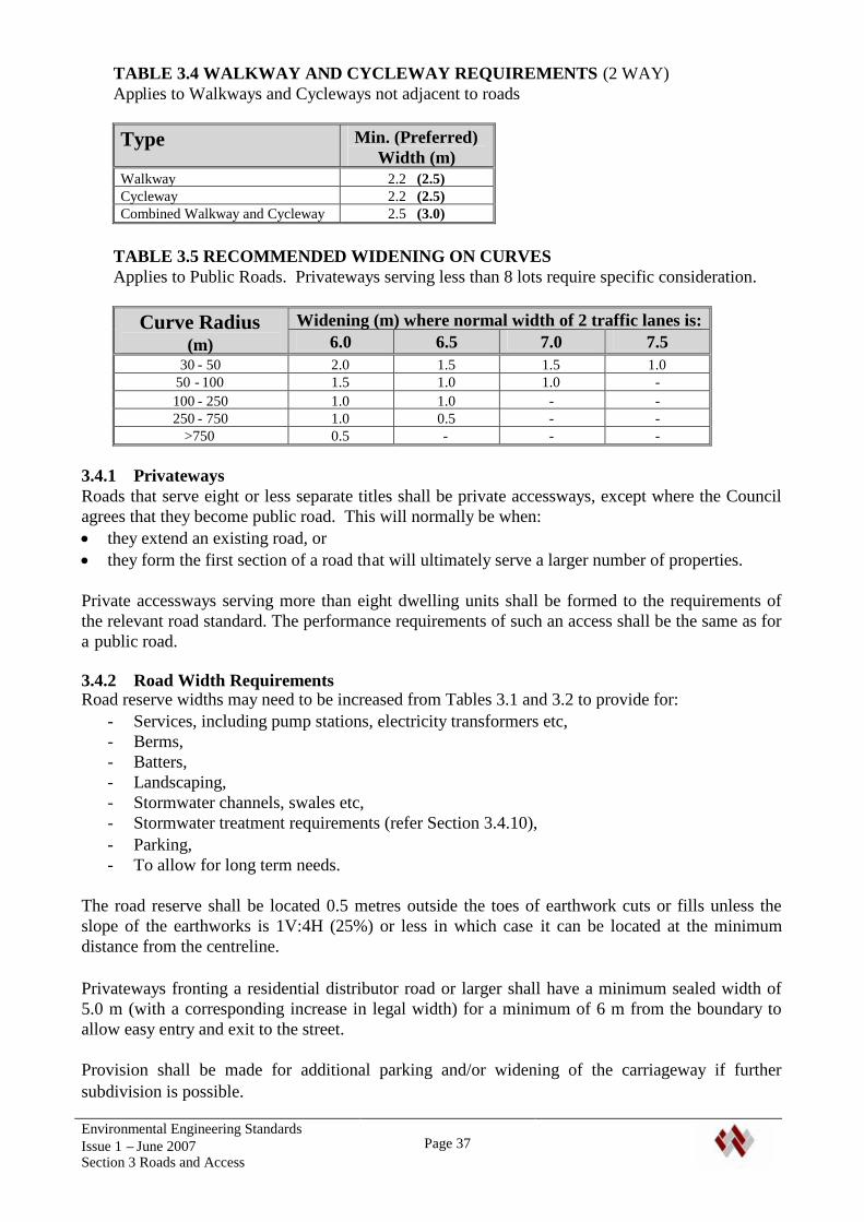
Environmental Engineering StandardsIssue 1 – June 2007Section 3 Roads and Access
Page 37
TABLE 3.4 WALKWAY AND CYCLEWAY REQUIREMENTS (2 WAY)Applies to Walkways and Cycleways not adjacent to roads
Type Min. (Preferred)Width (m)
Walkway 2.2 (2.5)Cycleway 2.2 (2.5)Combined Walkway and Cycleway 2.5 (3.0)
TABLE 3.5 RECOMMENDED WIDENING ON CURVESApplies to Public Roads. Privateways serving less than 8 lots require specific consideration.
Widening (m) where normal width of 2 traffic lanes is:Curve Radius(m) 6.0 6.5 7.0 7.5
30 - 50 2.0 1.5 1.5 1.050 - 100 1.5 1.0 1.0 -100 - 250 1.0 1.0 - -250 - 750 1.0 0.5 - -
>750 0.5 - - -
3.4.1 PrivatewaysRoads that serve eight or less separate titles shall be private accessways, except where the Councilagrees that they become public road. This will normally be when: they extend an existing road, or they form the first section of a road that will ultimately serve a larger number of properties.
Private accessways serving more than eight dwelling units shall be formed to the requirements ofthe relevant road standard. The performance requirements of such an access shall be the same as fora public road.
3.4.2 Road Width RequirementsRoad reserve widths may need to be increased from Tables 3.1 and 3.2 to provide for:
- Services, including pump stations, electricity transformers etc,- Berms,- Batters,- Landscaping,- Stormwater channels, swales etc,- Stormwater treatment requirements (refer Section 3.4.10),- Parking,- To allow for long term needs.
The road reserve shall be located 0.5 metres outside the toes of earthwork cuts or fills unless theslope of the earthworks is 1V:4H (25%) or less in which case it can be located at the minimumdistance from the centreline.
Privateways fronting a residential distributor road or larger shall have a minimum sealed width of5.0 m (with a corresponding increase in legal width) for a minimum of 6 m from the boundary toallow easy entry and exit to the street.
Provision shall be made for additional parking and/or widening of the carriageway if furthersubdivision is possible.
Environmental Engineering StandardsIssue 1 – June 2007Section 3 Roads and Access
Page 38
Where particular constraints exist that make the required widths impracticable, the developer mayapply for dispensation to these standards. The application should include the reasons for requiringthe dispensation, and any measures proposed to mitigate the effects of the reduced standard.
3.4.3 Provision for Further DevelopmentWhere further development of a site or adjoining land is possible, consideration shall be given to theneed or desirability of increasing the legal width of an access to permit such development in thefuture.
The Roading Manager may require a higher class of road than required for the particulardevelopment (including future stages of the development) to allow for development outside of thesubject property. Council Policy in relation to cost sharing shall apply to such situations. The costto Council shall be agreed with the Roading Manager prior to work commencing on site.
3.4.4 Public Transport and CyclingProvision for public transport and cycling routes and facilities shall be incorporated in the designwhere required by the Roading Manager. Reference should be made to Section 3.2.5 of NZS4404:2004 for guidance on Public Transport provisions.
Cycle lanes will be required on all residential collector and arterial roads, industrial/commercialcollector roads, and where the road forms a strategic link with other cycle routes. Cycle provisionsshall comply with Austroads Guide to Traffic Engineering Practice - Part 14 Bicycles, and the TNZNew Zealand Supplement.
3.4.5 SurfacingA sealed surface is required for:
- All urban privateways,- Rural privateways serving more than 5 lots, or with a gradient steeper than 18%,- All urban and rural roads.
Council may by specific approval permit rural roads to be unsealed. Approval will not normally begiven where the road will service properties that are predominantly urban, lifestyle, horticultural orsimilar, or that extend or join a sealed road. Approval for unsealed roads shall be confirmed at thetime of resource consent application.
Where new unsealed roads or privateways intersect with sealed roads, the seal shall be extended atleast 20m along the new road from the intersection.
3.4.6 Upgrading Existing RoadsWhere lots front an existing road, or when upgrading of an existing road is required because of newor increased traffic, the developer shall upgrade the affected road to comply with this standard. Thismay include road intersection construction or modification, the provision of footpaths andupgrading drainage to the development frontage.
3.4.7 Rural FootpathsFootpaths will normally be required in Living 3 Environment. These may be located adjacent to lotboundaries, separated from the carriageway by a watertable.
With Cluster development in Countryside and Coastal Countryside environments, the berm shall beformed and grassed so that it is suitable for pedestrian use.
Environmental Engineering StandardsIssue 1 – June 2007Section 3 Roads and Access
Page 39
In any Environment, provision of safety footpaths may be required because of the scale or type ofdevelopment, and/or hazards from traffic.
3.4.8 Design SpeedThe design speed for rural sub-collector and minor-collector roads may need to be increased fromthe speed in Table 3.3, to take account of the character of the development, e.g. it may need to beincreased to 100 km/hr where development is rural in character, rather than semi-urban.
3.4.9 Traffic CalmingIn residential streets, traffic calming measures may be used to enhance amenity values and safety, bylimiting speeds and discouraging through traffic from minor roads. Traffic calming measuresinclude providing horizontal bends of significant deviation (45or more), provision of speedhumps, traffic islands, raised pedestrian crossings, lane deflections, narrowing etc.
The provision of traffic calming measures should be discussed with the Roading Manager at anearly stage in the design. The use of any such measure is subject to specific approval by theRoading Manager
3.4.10 DrainageSurface drainage shall be incorporated in the design.
In urban areas this may be by kerb and channel or an alternative approved low-impact design.Alternative designs shall be adequately engineered, be designed to fit with the urban environment,and minimise maintenance requirements. Where there are particular maintenance or vehiclecrossing requirements, these shall be included in Consent Notices on the relevant property titles.Sub-surface drainage shall be provided below pavement/kerb edges in terms of good engineeringpractice.
In Living 3 Environments, surface drainage should normally be to the same standard as urban areas.
In other rural areas, side drains shall be provided for stormwater, and to keep groundwater below theroad pavement. Side drains shall be within the road reserve.
The drainage system shall include first flush treatment to Auckland Regional Council TP 10standards. Where ‘active’ treatment devices are proposed, the type of device shall be approved bythe Wastes and Drainage Manager. This is to rationalise maintenance requirements for such devicesacross the District.
3.4.11 Design LifeThe design life of roads shall be as follows: Pavements - at least 25 years based on Equivalent Standard Axle (ESA) or equivalent design
method. Surface and ground water drainage systems - not less than 100 years. Bridges and major culverts on public roads - not less than 100 years. Bridges and other structures on private accessways – not less than 100 years.
3.4.12 Vehicle CrossingsWhere a site has frontage to more than one road, the vehicle crossing shall be onto the road that hasthe lower class in the roading hierarchy, except where access to the road with higher class is shownto be more appropriate, and with the approval of the Roading Manager. Note that the maintenanceof vehicle crossings is the responsibility of the properties served.
Environmental Engineering StandardsIssue 1 – June 2007Section 3 Roads and Access
Page 40
The minimum distance of a vehicle crossing from an intersection is shown in TABLE 3.5. Distancesare measured parallel to the centreline of the frontage road from the centreline of the intersectingroad.
TABLE 3.5 - Minimum Distance of Vehicle Crossings from Intersections
Intersecting Road Type(Distance in metres)
Speed Limit 50 km/hr
Frontage RoadArterial Collector Local
Arterial 70 55 35Collector 40 40 20Local 25 25 10Speed Limit Over 50 km/hrArterial 180 180 90Collector 75 60 60Local 75 60 60
3.4.13 Roadside HazardsThe design shall include consideration of roadside hazards, particularly in high speed environments.The design shall consider ditches and roadside batters, culvert ends, posts, obstructions etc. Whererequired, slip bases on poles, the use of bevelled and grated culvert ends, pedestrian safety barriersand guardrails shall be provided.
3.4.14 State HighwaysProperties that front a State Highway or access a side road intersecting with a State Highway willneed to comply with the requirements of Transit New Zealand. Transit should be consulted beforeundertaking any planning associated with the site layout or access provisions.
3.5 GEOMETRIC DESIGN
3.5.1 GeneralThe design shall be carried out be carried out by a suitably qualified and experienced Engineerexperienced in road geometric design.
The Roading Manager may require the Developer to provide an independent Safety Audit of thedesign
3.5.2 UrbanMajor collector and arterial roads shall be designed to ‘Austroads Guide to Traffic EngineeringPractice’, incorporating horizontal transition curves.
Other urban roads and privateways may use circular curves with bend widening as required. Tables3.3 to 3.6 in NZS 4404:2004 may be used for the horizontal and vertical design of urban roadswithout horizontal transition curves.
Environmental Engineering StandardsIssue 1 – June 2007Section 3 Roads and Access
Page 41
3.5.3 RuralRural roads shall be designed to TNZ State Highway Geometric Design Manual or Austroads Guideto the Geometric Design of Rural Roads except as modified by Table 3.2. Low speed rural roadsand privateways may use circular curves without transition curves.
3.5.4 Sight DistancesSight distances for stopping, intersections, overtaking, curves and obstructions shall comply withSHEET 15, and other relevant standards, including Austroads Guide to Traffic EngineeringPractice.
3.6 PAVEMENT STRUCTURAL DESIGN
3.6.1 DesignPavements shall be designed by a qualified professional (Refer to Section 1.4). The design shall bein accordance with the AUSTROADS Pavement Design Manual (including its New Zealandsupplement) and relevant Transit New Zealand pavement materials standards. Pavement design forLocal Roads may use Austroads ‘Pavement Design for Light Traffic” supplement to the AustroadsPavement Design Guide. The design shall include adequate testing of the subgrade.
Calculations and investigations supporting the design, including testing of the subgrade shall besubmitted to Council with the engineering drawings. Laboratory testing shall be undertaken by anIANZ (or equivalent) accredited laboratory.
The Design Engineer shall provide a Design Certificate for the design.
3.6.2 GeneralGenerally flexible pavements shall be used for public roads. The Roading Manager may approvethe use of other types of pavements, and the design methods to be used.
Pavements shall be designed for the specified design life, based on the subgrade strength and trafficloading.
Soaked CBR values of the pavement subgrade shall be used, and the pavement designed for theestimated number of vehicle loadings over a 25-year design life. The minimum design traffic forurban cul-de-sacs shall be 5,000 ESAs per lane. In other environments, design loads shall bedetermined from the known and/or predicted heavy vehicle usage of the road, with adequatejustification provided with the application.
The following design methods for flexible pavements are acceptable;
Privateways serving up to 8 lots.Subgrade CBR shall be determined using a Scala Penetrometer.
The design may be a Specific Design using Mechanistic or Standard Chart Based Methods, ormay use the following standard:
Provided the subgrade CBR is greater than 7, Sub-base - 100 mm thickness of GAP 65 Basecourse – 100 mm GAP 40 Sealed surface.
Environmental Engineering StandardsIssue 1 – June 2007Section 3 Roads and Access
Page 42
Where the subgrade CBR is less than 7, the pavement shall be specifically designed.
All other roads below Collector Class.Design using either Mechanistic or Standard Chart Based Methods. Subgrade CBR determinedusing a Scala Penetrometer.
Collector Class and AboveMechanistic Design Method. Laboratory CBR testing. The design shall be carried out by anIQP.
Concrete Privateways may be constructed to the details in SHEET 4.
3.7 INTERSECTION DESIGNThe kerb line radius at intersections shall be consistent with likely vehicle and pedestrian usage.
The minimum radius shall be: 8m for residential roads. 13.5 m for road intersections above Collector Class, and in Commercial/industrial zoning, Major industrial intersections shall be specifically designed for B-Train units.
Lot corners shall be splayed a minimum of 6 m. Acceleration and deceleration facilities shall beprovided as necessary.
The preferred angle of intersection is 90. The minimum angle of carriageway intersection shouldbe 70for non-arterial roads. Carriageway alignment may be offset from the road reserve alignmentto improve the intersection angle. Tee intersections are preferred to cross intersections particularlyfrom minor roads. Acute-angle, wye and multi-leg intersections are to be avoided.
Centre to centre distances between side roads shall be: 40 m when intersecting a local road, 150 m when intersecting a local distributor class road or higher.
The number of road intersections should be minimised. Intersections on curves, particularly on theinside of curves shall be avoided. The location of the intersections shall take into account theminimum sight distances. Early consultation with Council is recommended.
Wherever practicable the gradient within 30m of intersections on local roads should not exceed 1 in10 (10%) and should preferably be less than 1 in 33 (3%).
For major intersections with more than 3,000 vehicles per day, an independent safety audit of thedesign shall be submitted to Council with evidence that recommendations of the safety auditor havebeen implemented.
Roundabouts shall be subject to specific approval by the Roading Manager.
3.8 CUL DE SAC HEADSResidential cul-de-sacs should comply with SHEET 10.
A central area may be provided for parking or planting. Where this is proposed, the layout shall bechecked for access by heavy vehicles using tracking curves.
Environmental Engineering StandardsIssue 1 – June 2007Section 3 Roads and Access
Page 43
The minimum kerb gradient shall be 0.5%.
No exit roads should be avoided in Commercial/industrial areas. Where they are used in theselocations a minimum turning circle radius of 15 m will be required.
Hammerhead or “T” cul-de-sacs may be approved where a standard circular head is unsuitable. Thelayout is subject to specific design. Compliance with Figure 3.5 in NZS 4404:2004 is an acceptablesolution in residential areas.
Where a cul de sac is formed, and it is intended that the road will be extended as part of a futurestage in a development, the provision for turning at the end of the cul de sac shall be specificallyconsidered. The design shall be subject to specific approval by the Roading Manager.
3.9 BERMS, FOOTPATHS ETC
3.9.1 Urban BermsThe shape, slope and vegetation of berms shall be satisfactory for stormwater runoff, maintenance,location of services, landscaping and vehicle crossings to properties. To achieve satisfactorydrainage, the crossfall of berms should be at least 1 in 30 (3%) but may be varied between 1 in 30(3%) and 1 in 6 (17%). For berm crossfalls greater than 1 in 12.5 (8%), the designer shall producecross sections to demonstrate crossings can be satisfactorily negotiated by a 90th percentile car.Compliance with Figure 3.9 in NZS 4404:2004 is an acceptable solution.
The berm crossfall shall normally slope towards the road. Where this is not possible, a positivedrainage system shall be provided that directs flow to a stormwater system. This may require the useof dished channels and sumps. Under no circumstances may water from the berm be concentratedonto any of the lots, or stormwater flow affect pedestrian traffic on footpaths.
Berms shall be topsoiled to a compacted depth of 100mm, and grassed. The whole of the berm areashall be suitable for mowing.
3.9.2 Rural BermsIn general, rural berms shall be constructed to the same standard as urban berms. The width of theberm shall not be less than 2 m between the roadside channel and road reserve boundary. Provisionshall be made for footpaths in Living 3 Environment, and level berms suitable for pedestrian use inthe vicinity of cluster developments in Countryside and Coastal Countryside Environments.
3.9.3 FootpathsFootpaths shall comply with the following:
The minimum width of footpaths shall be 1.4 m (not including kerb width). In areas of highpedestrian use, the Council may require local widening.
Footpath crossfall shall be 3%. Slope should generally not exceed 12.5%. The design shall avoid steps or unevenness. The centreline radius of horizontal curves shall be no less than 3 metres. Footpath surfacing shall comply with D1/AS1 of the NZ Building Code for wet slip
resistance for sloping surfaces.
Unless specifically approved, footpaths shall be concrete, with a broomed or exposed aggregatefinish. The use of coloured exposed aggregate, patterned surfaces or other non-standard materialswill require the specific approval of the Roading Manager.
Environmental Engineering StandardsIssue 1 – June 2007Section 3 Roads and Access
Page 44
The Roading Manager may approve: Interlocking pavers on 30 mm sand on 100 mm compacted basecourse, 25 mm M10 Asphaltic Concrete on seal coat on 150 mm compacted GAP 40 basecourse.
Note that the above standards may not be sufficient for footpaths where vehicles may access, e.g.vehicle crossings or footpaths to cul-de-sac heads. These will require specific consideration.
Paving units shall be readily available standard units, and shall comply with NZS 3116. Thesepavements shall be designed to have a 25 year life under all expected load conditions. The edges ofthe paved areas shall be adequately confined, normally by timber or concrete nibs.
Pram and wheelchair crossings shall be provided at all road intersections and pedestrian crossings.Where possible, sumps should be sited on the top side of the crossing. The crossing entrance shallbe connected to the footpaths and have a maximum gradient of 1 in 8 (12.5%).
Construction Details are given in SHEET 9.
3.9.4 Pedestrian Accessways and CyclewaysPedestrian accessways between roads shall be paved to their full width, in accordance with therequirements for footpaths including stormwater control and lighting. Both sides of pedestrianaccessways shall be bounded by a Type 3 fence with mowing strip. They shall be provided withcycle barriers at each end suitable for disabled access.
Tracks for bicycle use shall be constructed to standards specified for footpaths. Where used by bothpedestrians and cyclists, the minimum paved width shall be 2.5m assuming no side obstructions orwalls. Where these are present, additional clearances should be provided. Stormwater disposal,fencing, handrails, and lighting shall be provided as appropriate to the specific situation.
3.9.5 LandscapingReference is made to Section 7 of this standard.
3.10 VEHICLE CROSSINGSA vehicle crossing shall be provided between the kerb line and the boundary at the entrance to allentrance strips to rear lots, privateways and service lanes, and at any other place where the locationof the future driveway to a lot can be determined with reasonable certainty.
Vehicle crossings shall be designed so that a 90th percentile car may use them without grounding.
Vehicle crossings in urban areas shall normally be constructed in reinforced concrete with surfacefinish to match adjacent footpaths. Approval may be given for Interlocking pavers or AsphalticConcrete.
Vehicle crossings in rural areas may be chip seal, asphaltic concrete or reinforced concrete. Whereconcrete is used, the start of the concrete shall be not less than 0.5 m from the existing edge of seal,or 0.5 m outside of the carriageway width required by this standard, whichever is the further. Thearea between the concrete crossing and edge of seal shall be sealed with 30 mm asphaltic concreteover a waterproofing seal coat.
A level area shall be provided at the intersection with the road, with adequate sight distances.
Environmental Engineering StandardsIssue 1 – June 2007Section 3 Roads and Access
Page 45
Where an unsealed accessway joins a sealed road, the accessway shall be sealed to at least theproperty boundary, to prevent metal migrating onto the road. Where accessways and drivewaysslope down towards a sealed road at a gradient of 8% or more, the accessway shall be sealed for aminimum distance of 10 metres from the edge of the road.
3.11 PRIVATE ACCESSWAYSThe maximum gradient shall be: 12.5% for the first 5 m from the boundary Remainder 22%. The maximum gradient should be restricted to straight sections of road where
practical.
The minimum crossfall shall be 3%.
Corner splays for Privateways shall be a minimum of 3 m at intersections. For accesses constructedto Residential Road standards, corner splays shall be as for road intersections.
Where a private accessway is gated, the gates shall be located far enough from the road andprovided with turning provisions, such that a 90th percentile car may enter the accessway and turnaround, without passing the gates or affecting through traffic.
On Privateways less than 4.5 m in width, passing bays with a width of 6.0 m shall be provided. Thespacing between bays should be approximately 50 m in urban areas, and 100 m in rural areas,however at the discretion of Council this may be adjusted based on development density andadequate visibility.
Where a private accessway contains: a public water main (as approved by the Water Services Manager – See Section 6.8.1), or a public sewer gravity main or rising main,the accessway width shall be sufficient to allow maintenance access for these service mains clear ofother services, using minimum clearances required by Table 6.6.
Where a Sewer Pump Station or Fire Hydrant is located within, or accessed via a private accessway,an adequate turning and parking area for fire appliances and maintenance vehicles in the vicinity ofthe pump station or hydrant shall be provided and the access designed to take heavy vehicles.
Surface water from an urban accessway shall be collected in a sump and directed to a stormwaterreticulation system or approved outfall location. It shall not discharge over a footpath or directlyonto a road carriageway. Where accesses fall away from the road, stormwater sumps shall beprovided as necessary to ensure that stormwater from the access does not concentrate onto any lot.
Rural accesses may drain to a road side drain.
3.12 TRAFFIC SERVICES, SIGNAGE, AND ROAD FURNITURERoad marking and traffic signs shall be provided, complying with the TNZ Manual of Traffic Signsand Markings (MOTSAM) and NZS 5414 : Specification for Construction of Traffic Signs. Signsshall include stop and give-way signs, keep left signs on islands, warning signs etc.
Name signs for Roads, Privateways, walkways, cycleways and service lanes shall be erected at allintersections. Name signs shall comply with the details in SHEETS 5 and 6.“No exit” signs are to be erected on all cul-de-sacs or dead end roads. “Private Access”supplementary blades are to erected on all private roads and accessways.
Environmental Engineering StandardsIssue 1 – June 2007Section 3 Roads and Access
Page 46
All signs on urban State Highways, Arterial Roads and Local Roads shall have VIP standard orequivalent sheeting in accordance with AS/NZS 1906.1. All other signs shall have Class 2 sheeting.
Roadmarking includes marking of intersections, centrelines, parking areas etc. Rural roads shall bemarked with a dotted centreline and white raised pavement markers at 20 metre intervals along thecentreline. Edgelines are required in locations where additional delineation is necessary for safetyreasons (e.g. on the outside of sharp bends).
3.13 ROAD NAMESThe provisions of the Whangarei District Council Road Naming Policy – April 2005 shall befollowed, with AS/NZS 4819:2003 as a working guide to the naming policy.
The applicant shall identify all roads, privateways, accessway, rights-of-ways etc on theconcept/survey plan submitted with the Resource Consent Application.
For each new legal or public road, service lane or public accessway, and each new private road orprivateway (including private accessway, private access lot, private right of way etc) serving 5 ormore lots or dwellings, the applicant shall submit three names in order of preference for Councilapproval. These names shall be submitted with a brief explanation of the reasons for the selectionincluding any meaning and/or historical background with the Resource Consent Application. Thisis to be accompanied by a clearly marked locality map.
Council staff will check the names for relevance and duplication prior to submission to the Council.The Council's decision will be notified to the applicant so that provision of road name signage, etc.can be made by the Developer.
3.14 STREET LIGHTINGStreet lighting shall be provided in all urban streets, walkways and cycleways, and areas set asidefor frequent public use. It shall also be provided at major rural intersections.
Street lighting shall be designed by an IQP for the functional classification of the road to theillumination criteria of AS/NZS 1158.
Lighting columns shall normally be galvanised hollow steel. Lamps shall be down facing onoutreach arms. Shielded fixtures shall be used where light spill may affect adjacent properties.Where there is a risk of vehicular impact, columns shall have shear bases.
The following guidelines should generally be followed: Mounting height not less than 8.5 m Standard 100W HP Sodium Lamps Cabling taken to the closest pillar box and a fuse provided at this location
A limited range of decorative lamps may be used with the approval of the Roading Manager.
3.15 BRIDGES AND CULVERTS
3.15.1 GeneralThe design shall be carried out by an IQP, in accordance with the Transit New Zealand BridgeManual. The design load shall be HN HO 72. Note that culverts with a waterway area greater than3.4 m2 are regarded as bridges under the TNZ bridge manual.

Environmental Engineering StandardsIssue 1 – June 2007Section 3 Roads and Access
Page 47
Appendix D of the Bridge Manual shall not be used for bridges on public roads, except with thespecific consent of the Roading Manager.
The width shall accommodate the full carriageway width (2 way traffic) including cycle lanes andfootpaths. Provision shall be made in the design for cables, pipelines etc.
Side barriers, including barriers to approaches as appropriate shall be provided. These may be W-section steel guardrail or concrete barriers. The design standards and details shall be confirmedwith the Roading Manager at an early stage. Pedestrian barriers shall be provided at footpaths.
Wing walls, and scour protection shall be provided to protect batter slopes. Foundations shall beprotected against settlement and scour. In order to mitigate blockages due to debris build-up duringflood events, bridges and culverts shall be designed to minimise or eliminate obstructions includingpiers/supports etc within the 1:100 year ARI water level.
3.15.2 Bridges on Private AccesswaysFor bridges and other structures on private accessways serving up to 8 lots, the design requirementsof Appendix D of the TNZ Bridge Manual may be used, subject to the following conditions:
The access will not become a through route, The alignment has a speed value below 70 km/h, Use by logging trucks is unlikely, No significant overloads are expected to occur, or the bridge can be bypassed.
Appendix D allows the replacement of the HN design load with 0.85 HN. The HO load need not beconsidered.
The level of side protection shall be appropriate to the situation. The minimum acceptable shall bethe provision of kerbs and marking posts where the height above the watercourse is no more than1.0 m.
3.15.3 Waterway DesignWaterway design shall be carried out by an IQP in accordance with the Bridge Manual and Section4 of this Manual.
Overall DesignThe total waterway shall be designed to achieve: No heading up or increases to water levels upstream during a 10 year ARI flood event, Able to pass a 100 year ARI flood without significant damage to the road and waterway
structures, Obstructions and risk of blockage in the waterway area are minimised.
Level of Serviceability to TrafficThe waterway shall achieve: on arterial road (> 2500 vpd), no interruption to traffic during a 100 year ARI flood event, for roads between 250 and 2500 vpd, no interruption to traffic during a 50 year ARI flood event. for minor roads (< 250 vpd), no interruption to traffic during a 10 year ARI flood event.
Environmental Engineering StandardsIssue 1 – June 2007Section 3 Roads and Access
Page 48
3.15.4 ConsentsThe Developer shall obtain all Resource Consents and Building Consents required for bridges,retaining walls and culverts.
Bridges, retaining walls etc, are classed as buildings under the Building Act, and therefore require aBuilding Consent before construction. All such structures shall be designed according to therequirements of the Building Act, and the construction shall be supervised by a suitably qualifiedperson. The design and supervision of the construction shall be certified by thedesigner/construction supervisor as complying with the drawings and specifications, and therequirements of the Building Act. It is noted that public use of a building is not permitted until aCertificate for Public Use or Code Compliance Certificate is obtained.
3.15.5 Retaining WallsRetaining walls shall be designed to carry all expected soil loads and overloads as described in theBridge Manual with an adequate factor of safety.
3.16 ROAD DRAINAGERefer to Section 4 for the calculation and design of stormwater run-off, and treatment requirements.
3.16.1 Subsurface DrainageSubsurface drains shall be provided on both sides of all urban roads except where it can bedemonstrated that it is not necessary (e.g. low water table and ground with high permeability).Rural roads in cut will also normally require subsurface drainage.
Subsurface drains shall have adequate flushing locations, and shall discharge to the stormwatersystem.
3.16.2 Surface DrainageThe design shall generally comply with Transit New Zealand’s guideline document “HighwaySurface Drainage : Design Guide for Highways with a Positive Collection System”. Section 4 ofthis standard should be referred to for additional requirements for surface water treatment.
3.16.3 Side Drains, Kerb and ChannelsWater from roads shall be directed to side drains/water tables, kerbs and channels, swales or otherapproved system, sized to suit the flows, with discharge to sumps, drains or other approved outletsat regular intervals. All outlets shall be protected from scour, and located to minimise the risk ofslope instability.
Kerb details are shown in SHEET 12. Mountable kerbs shall only be used on Service Lanes, orwith specific consent of the Roading Manager.
3.16.4 SumpsSumps shall be provided to collect stormwater from channels. Stormwater treatment shall beincorporated into sumps using sump filters approved by the Council, where no other overalltreatment mechanisms are proposed.
Treatment of the ‘first flush’ of stormwater shall comply with ARC TP10 standards. This will needto be considered in relation to overall treatment requirements.
Sumps shall be provided to accept the design flow, including overland flow intercepted by the road,based on the sump capacity (approximately 28 l/s for single back entry sump). The capacity of non-standard sumps and grates used on accessways etc. shall be established.
Environmental Engineering StandardsIssue 1 – June 2007Section 3 Roads and Access
Page 49
The maximum spacing of sumps is 90 m. Double sumps shall be provided at low points. Sumpsshall also be provided where there is potential for ponding, where flow could leave the kerb andchannel, and upstream of footpath crossing locations.
Sump leads shall be at least 300mm NB for single sumps. Double sumps shall have a single375mm NB lead, or separate 300mm leads from each sump. Sump gratings shall be suitable forcrossing by bicycles.
3.17 ROAD CONSTRUCTION
3.17.1 PavementThis section applies to flexible pavements.
Road formation will normally consist of the sub-base constructed on the existing material(subgrade). A layer of filter fabric may be required to separate these layers. A basecourse layer isconstructed over the sub-base, with surfacing laid on top.
Unsealed roads shall include an upper layer of well graded running course aggregate of maximumparticle size 25mm, minimum thickness 50mm and containing sufficient fine material to bind thelayer and confine large particles in the underlying structural pavement layer.
3.17.2 Material StandardsThe pavement structural design shall conform to the requirements of Section 3.6 of this standard.The design may utilise high strength materials (e.g. TNZ M/4 basecourse), or lower strengthmodified materials (e.g. lime or cement stabilised GAP 40 basecourse).
The designer shall specify the material standards required by the design.
The applicant shall provide test data to confirm compliance with the material standards required forthe design.
3.17.2.1 Standards for Unmodified Basecourse MaterialsBasecourse material shall comply with TNZ M/4 requirements (all passing 40mm – AP40) orequivalent.
3.17.2.2 Standards for Local Materials in Modified PavementsThe material standards in Table 3.6 and grading limits in Table 3.7 have been found to be suitablefor roads in the Whangarei District, when used in a lime stabilised pavement.
TABLE 3.6 Material Standards (Suitable for Lime Stabilised Pavements)
Test Standard
CrushingResistance (kN)
TNZ M4 120
Quality Index NZS 4407:1991 Test 3.11 AA, AB, AC, BA, or CA
Clay Index NZS 4407 Test 3.5 >3.5, <8.0
Environmental Engineering StandardsIssue 1 – June 2007Section 3 Roads and Access
Page 50
CaliforniaBearing Ratio
Compacted to NZS 4402:1986,Test 4.1.3Tested to NZS 4407, Test 3.15
Not less than 40%
Proportion ofBroken Rock
For each aggregate fraction, not less than50% by weight shall have 2 or more brokenfaces
Lime Reactivity Quick Response Test inaccordance with RRUTechnical RecommendationNo. 2
Lime Reactive
TABLE 3.7 Grading Limits (when delivered or following compaction)
Running Course GAP 40 (Basecourse) GAP 65 (Sub base)
100% of the material less than19mm maximum size
100% of material less than37.5mm maximum size
100% of material less than75mm maximum size
60% max. passing a 4.75mmsieve
Between 63-81% passing a19mm sieve
At least 45% passing a 19mmsieve
31% max. passing a 0.6mmsieve
12-25% passing a 1.18mmsieve
12-25% passing a 1.18mmsieve
3.17.3 ConstructionThe designer shall inspect and as necessary test the exposed subgrade to confirm that it is suitablefor the design. Soft areas shall be removed and replaced with GAP aggregate. Wet areas shall bedrained using subsoil drainage with an outlet to a sump or drainage channel. Outlets to a drainagechannel shall have a concrete or grouted rock surround.
Compaction of pavement materials shall be carried out in layers not exceeding 150 mm thick.
The basecourse shall have a stone mosaic surface after sweeping.
Acceptance by Council is subject to completion of all testing, and presentation of test results.Normally Clegg Hammer testing will be carried out in the presence of Council staff.
The road shall be sealed as soon as possible after acceptance by Council, subject to suitable weatherconditions.
3.17.4 Testing Prior to Sealing
TABLE 3.8 Pavement Test Requirements
Test Standard Requirement CriteriaPavement LayerDensity(Nuclear
NZS 4407Test 4.2.2
All roads that will become publicroads.Frequency to TNZ B/2
Sub-base 98% RelativeDensity,Basecourse 100%
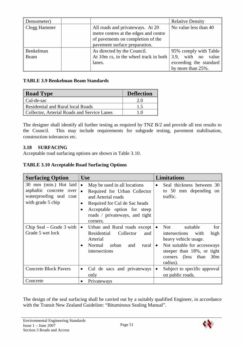
Environmental Engineering StandardsIssue 1 – June 2007Section 3 Roads and Access
Page 51
Densometer) Relative DensityClegg Hammer All roads and privateways. At 20
metre centres at the edges and centreof pavements on completion of thepavement surface preparation.
No value less than 40
BenkelmanBeam
As directed by the Council.At 10m cs, in the wheel track in bothlanes.
95% comply with Table3.9, with no valueexceeding the standardby more than 25%.
TABLE 3.9 Benkelman Beam Standards
Road Type DeflectionCul-de-sac 2.0Residential and Rural local Roads 1.5Collector, Arterial Roads and Service Lanes 1.0
The designer shall identify all further testing as required by TNZ B/2 and provide all test results tothe Council. This may include requirements for subgrade testing, pavement stabilisation,construction tolerances etc.
3.18 SURFACINGAcceptable road surfacing options are shown in Table 3.10.
TABLE 3.10 Acceptable Road Surfacing Options
Surfacing Option Use Limitations30 mm (min.) Hot laidasphaltic concrete overwaterproofing seal coatwith grade 5 chip
May be used in all locations Required for Urban Collector
and Arterial roads Required for Cul de Sac heads Acceptable option for steep
roads / privateways, and tightcorners.
Seal thickness between 30to 50 mm depending ontraffic.
Chip Seal – Grade 3 withGrade 5 wet lock
Urban and Rural roads exceptResidential Collector andArterial
Normal urban and ruralintersections
Not suitable forintersections with highheavy vehicle usage.
Not suitable for accesswayssteeper than 18%, or tightcorners (less than 30mradius).
Concrete Block Pavers Cul de sacs and privatewaysonly
Subject to specific approvalon public roads.
Concrete Privateways
The design of the seal surfacing shall be carried out by a suitably qualified Engineer, in accordancewith the Transit New Zealand Guideline: “Bituminous Sealing Manual”.
Environmental Engineering StandardsIssue 1 – June 2007Section 3 Roads and Access
Page 52
Seal binder, seal chip and adhesion agents shall be in accordance with TNZ specifications M/1, M/6and M/13. Chip seals shall be applied in accordance with TNZ P/3 (initial seals) or P/17 (reseals).Asphaltic concrete shall comply with TNZ M/10 and be constructed in accordance with TNZ P/9.
If special sealing measures are required at an intersection, the applicable intersection area shallinclude a distance of 20 metres beyond the intersecting roads or accesses.
Parking areas shall be surfaced with a chip seal followed by a Asphaltic concrete (AC) overlay, orhigher standard of surfacing (eg concrete).
Pavement units to NZS 3116 may be approved for specific projects. Masonry units shall be readilyavailable standard units, complying with NZS 3116. The design of the road shall be carried out by asuitably qualified person. Edges of the paved areas shall be adequately confined, normally byconcrete nibs.
Concrete for roads and crossings shall come from a special grade plant as defined in NZS 3109.
The minimum concrete strength at 28 days shall comply with NZS be: Roads and Crossings, kerbs and channels where vehicles may cross 30 MPa Footpaths, Kerb and Channels (excluding mountable kerbs, dished channels etc) 20 MPa
3.19 SURFACE TOLERANCES AND FINISHINGThe finished surface of the road shall have no abrupt or abnormal deviations, and no areas shallpond water.
The surface shall be of uniform texture, and satisfy density standards appropriate to the surfacing.
Skid resistance and surface texture of roads of collector class or higher, with a design speedexceeding 70 km/h shall satisfy TNZ T10.
3.20 COMPLETION
3.20.1 GeneralOn completion of all other works, the berms shall be spread with first quality topsoil and compactedto a depth of 100 mm. The topsoil shall be graded to kerb top and footpath edges, and may befinished 15 mm high to allow for settlement except on the low side of the footpath where the topsoilshall be finished flush to prevent water ponding.
Superfluous vehicle entrance crossings and similar along the road frontage of any development areto be removed and any broken footpaths or other non-complying facilities or services be repaired asnecessary at the applicants expense.
After topsoiling, the berms shall be sown with a seed mixture the generic characteristics of whichare such that the grass cover is low growing, with a robust and deep rooting system, and well suitedto the soil conditions. An 80% grass strike, must be achieved and the grassed areas shall bemaintained free of excessive weed growth and shall be kept mown throughout the maintenanceperiod.
Environmental Engineering StandardsIssue 1 – June 2007Section 3 Roads and Access
Page 53
All poles, sign posts, light standards, markers, power transformers, boxes, etc, set in grass bermsshall be finished off with a concrete mowing strip surrounding the base, flush with finished groundlevel, 150 mm wide and 75 mm thick.
Sealed roads and privateways shall be swept, and all sumps shall be cleaned out.
3.20.2 As-Built Drawings and Schedule of Asset InformationA set of drawings and schedule of asset information shall be submitted as per Section 1.7 of thisStandard. These shall clearly and accurately show the as-built locations and details of allinfrastructure provided as part of the work, including any modifications made to the existing system.
The As Built drawings may be checked on site for accuracy on completion of the subdivisionor development. A certificate of completion for the works will not be issued until acceptable As-Built drawings have been produced.
The drawings shall identify assets that have been removed or decommissioned.
3.20.3 RAMM DataRAMM data shall be provided as required by Section 1.8 of this standard.
3.21 DEFECTS LIABILITYA defects liability period of 12 months is required for road construction works. During this period,the Council will carry out normal maintenance work on the public roads. A Performance Bond willbe required for the works in terms of Section 1.13 of this Standard.
3.22 DRAWINGSThe following drawings in APPENDIX A apply to this section:
SHEET 1 STANDARD DRAWING SYMBOLSSHEET 2 RURAL PRIVATEWAY CROSS SECTIONSSHEET 2A FURTHER NOTES TO RURAL PRIVATEWAY CROSS SECTIONSSHEET 3 RURAL VEHICLE ENTRANCE CROSSING DETAILSSHEET 3A FURTHER NOTES TO RURAL VEHICLE ENTRANCE CROSSING DETAILSSHEET 4 URBAN PRIVATEWAY CROSS SECTIONSSHEET 4A FURTHER NOTES TO URBAN PRIVATEWAY CROSS SECTIONSSHEET 5 STANDARD STREET SIGNSSHEET 6 STREET SIGNS – PRIVATE ROW, ACCESS LOT, COMMON AREA OR PRIVATE
ROADSHEET 7 RESIDENTIAL AND COMMERCIAL AREA VEHICLE CROSSING DETAILSSHEET 8 RURAL ROAD CROSS SECTIONSSHEET 9 URBAN ROAD CROSS SECTIONSSHEET 10 CUL DE SAC TURNING DETAILSSHEET 11 RECOMMENDED SERVICE LOCATIONSSHEET 11A FURTHER NOTES TO RECOMMENDED SERVICE LOCATIONSSHEET 12 KERB AND CHANNEL DETAILSSHEET 13 TYPICAL KERB AND SUBSOIL DRAIN DETAILSSHEET 14 PRAM CROSSING DETAILSSHEET 15 TRAFFIC SIGHT LINES FOR NON-SIGNALISED INTERSECTIONSSHEET 16 SCALA PENETROMETER CHARTSHEET 17 DESIGN CHART FOR FLEXIBLE PAVEMENTSSHEET 18 PIPE BEDDING AND BACKFILLSHEET 19 PIPE PROTECTION AND BULKHEADSSHEET 20 INLET AND OUTLET STRUCTURESSHEET 22 SUMP DETAILS
Environmental Engineering StandardsIssue 1 – June 2007Section 4 Stormwater Drainage
Page 55
4. STORMWATER DRAINAGE
4.1 GENERAL REQUIREMENTS
4.1.1 GeneralThis Section covers the requirements for Stormwater Drainage works.
Stormwater drainage is required to collect and convey surface water run-off, and for groundwatercontrol, in order to minimise adverse effects including flooding, erosion and sedimentation andwater quality effects.
The stormwater system for a development, including any upgrading of existing downstream systemswhere required, shall provide: Piped reticulation and/or storage or an alternative low impact system through urban areas, Retention and enhancement of existing natural waterways through open space areas, including
parks and reserves, Allowance for changes in weather patterns from global warming.
The piping of existing watercourses or open drains will not generally be permitted.
In rural areas, a discharge to an existing drainage channel may be approved, subject to appropriateconditions, and the principles set out above.
4.2 REFERENCED DOCUMENTSThe following documents shall be read in conjunction with this section of these standards: Whangarei District Plan (WDC) Regional Soil and Water Plan for Northland (NRC) Regional Coastal Plan for Northland (NRC) Transit New Zealand Bridge Manual (TNZ) Auckland Regional Council (ARC) Technical Publication (TP) No. 124, Low Impact Design
Manual for the Auckland Region ARC TP No 10, Design Guideline Manual, Stormwater Treatment Devices, Auckland City Council ‘On-site Stormwater Management Manual’ and ‘Soakage Design
Manual’, Ministry for the Environment, October 2004, On-Site Stormwater Management Guideline SNZ HB 44.2001, Subdivision for People and the Environment. WDC Catchment Drainage Plans, or Catchment Management Plans, WDC Stormwater/Surface Water By-Law (when adopted) WDC Sustainable Stormwater Drainage Guidance Document (when developed)
Where aspects of the design are not covered by this section or the above documents, the followingstandards may be referenced. Adoption of any practises outside of the Council documentation mustfirst be approved by the Wastewater and Drainage Services Manager.
NZS 4404:2004 Land Development and Subdivision Engineering, New Zealand Building Code (NZBC) - Approved Document Clause E1 – Surface Water
(available on-line at:http://www.building.dbh.govt.nz/e/publish/compliance_docs_approved.shtml)

Environmental Engineering StandardsIssue 1 – June 2007Section 4 Stormwater Drainage
Page 56
The most up to date of these publications shall supersede any conflicting requirements of olderdocuments.
4.3 SUBMISSION OF APPLICATION
4.3.1 Supporting Information and Calculations
The application shall include supporting information and calculations that demonstrate that:
The design is consistent with requirements for the whole of the catchment, Stormwater quality and quantity requirements are satisfied, Pipeline design provides the required level of service Secondary flow paths are available, and adequate for the design volumes. Flood heights shall
be assessed and restrictions and/or easements required shall be identified. Overland flow paths including flood levels, flow path boundaries and easement requirements
shall be clearly identified in Consent and As-Built drawings.
The design shall identify off-site effects, including changes to:
flow peaks (where permitted)and frequency patterns, flood water levels, contamination levels and erosion, and concentration of stormwater on downstream properties.
Measures to mitigate any detrimental effects shall be identified
Operational and maintenance requirements for any water quantity and/or quality control structuresshall be provided.
Catchment design shall be carried out by an Independent Qualified Person (IQP), experienced incatchment analysis who shall provide a design certificate identifying the design standards used, andcertifying that the design complies with these standards. On completion of the works, the IQP shallcertify that the completed works achieve the required design criteria..
4.3.2 Design Drawings and SpecificationsDesign drawings complying with the requirements of Section 1.5 and 1.6 shall be provided forapproval.
4.3.3 Approval of DesignThe drawings and calculations will be reviewed by the Wastewater and Drainage Services Manageror his/her representative. The drawings showing any alterations shall be returned to the applicant’srepresentative. If adjustments to the design are required a new set of amended drawings shall besubmitted to the Council prior to approval being granted. Only drawings stamped and signed by theWastewater and Drainage Services Manager or his / her representative shall be deemed approveddrawings. Unless specifically stated otherwise, the approval of drawings does not supersede therequirements or obligations of these standards.
4.4 STORMWATER ASSESSMENT STRATEGYThe stormwater assessment strategy shall review options in the following order of priority:
Environmental Engineering StandardsIssue 1 – June 2007Section 4 Stormwater Drainage
Page 57
Source ControlSustainable systems within individual lots attending to both water quality and runoff volumes.Engineer designed infiltration techniques shall be used where ground stability and soil permeabilitypermit their use. System types shall be identified and designed to enable consent notices to beapplied to the titles with an approved mechanism in place to require their implementation.
Site ControlAttenuation, detention and treatment systems designed to receive runoff from the development as awhole or in part. Where it is intended to locate such systems in WDC reserves (existing orproposed) early discussion with the WDC Parks division is encouraged. Subject to suitableapproved detailing and construction such systems may be vested with WDC with provision ofsuitable operation and maintenance documents in an approved format.
Regional ControlEither a developer funded upgrading of the entire downstream network to facilitate connection fromthe development or provision of an agreed contribution towards a WDC strategic attenuationprovision where identified. This may require a comprehensive development assessment of the wholecatchment.
The connection of a new development to an existing reticulated network, open drain or watercoursein an unattenuated and/or untreated state will not be considered unless: The options identified above have been evaluated and demonstrated as unworkable to the
satisfaction of the WDC drainage engineer, and The effect of the discharge is no more than minor.
4.5 LOW-IMPACT DESIGN AND STORMWATER TREATMENTThe use of low impact design, including the use of grassed swales, open channels, ponds, wetlands,rain gardens, in-ground stormwater detention structures etc is promoted by the Council to reduce theimpacts of stormwater discharge by improving quality and/or reducing quantity of the discharge.Such concepts need to be considered early in the design process.
Low Impact Design and/or Stormwater Treatment will be required as follows:
By conditions of a Resource Consent (including conditions and recommendations in‘Catchment Drainage Plans’ or Catchment Management Plans). Note that the WDC mayimpose additional conditions to those required by a Catchment Management Plan to resolve orprevent exacerbation of known problems within the catchment.
To meet water quality guidelines in the Regional Water and Soil Plan for Northland and / orWDC held resource consent conditions for SW discharge,
To comply with requirements of a relevant by-law, To restrict impacts on downstream properties from a change in use of land, or As required by the Wastes and Drainage Manager.
Well-designed and maintained alternative systems can enhance local amenity and ecological values.
Early consultation with the Council is recommended to identify the impact and suitability of thedesign, including maintenance requirements. Consultation is also required regarding the selectionof proprietary stormwater treatment devices, so that the Council can standardise types across theDistrict.
Reference should be made to:
Environmental Engineering StandardsIssue 1 – June 2007Section 4 Stormwater Drainage
Page 58
Auckland Regional Council (ARC) Technical Publication (TP) No. 124, Low Impact DesignManual for the Auckland Region
ARC TP No 10, Design Guideline Manual, Stormwater Treatment Devices, SNZ HB 44.2001, Subdivision for People and the Environment.
4.6 NORTHLAND REGIONAL COUNCIL AUTHORISATIONWhere a development requires connection to an existing and/or construction of a new piped or openchannel disposal system, the following general requirements apply:
Developments within catchments with operative Catchment Drainage or Management Plans(CDP or CMP) that comply with the requirements of the Plan, will not require separate resourceconsents for stormwater diversion and discharge from the Northland Regional Council. Itshould be noted that CDP/CMPs in the Whangarei District do not cover all urban areas.
Where an operative CDP/CMP is not in place or the proposal is not consistent with an operativeCDP/CMP, the applicant shall obtain all resource consents from the Northland Regional Councilrequired for the work. Where a Consent is for a facility that will be taken over by the Council,the application shall be in the name of the District Council. The District Council shall beconsulted about stormwater management at an early stage, before detailed design commences.
In all circumstances, the relevant requirements of the Stormwater Bylaw shall be complied with.
The Council will advise whether the area of a development is covered by a CDP or CMP, andconditions associated with it. WDC reserves the right to apply surface water conditions / dischargeconstraints in addition to those imposed by NRC to safeguard elements of the WDC controlleddownstream networks.
4.7 PRIMARY AND SECONDARY SYSTEMS
4.7.1 Catchment BoundariesCatchment and sub-catchment boundaries shall be identified and shown on a plan, with catchmentareas noted. This plan shall identify watercourses, reticulation, and secondary flow paths.
4.7.2 Primary and Secondary SystemsThe stormwater system shall consist of: A primary system of pipes and/or waterways to cater for more frequent rainfall events, and A secondary system consisting of open channels, flood plains and overland flow paths to cater
for higher intensity events, and blockages in the primary system (refer to Table 4.1).
Where a secondary system is not available, the primary system shall be designed to provide a levelof protection required of secondary systems. This shall include an analysis of the effects ofblockages of pipes and culverts. This is particularly important with smaller culvert sizes, or wherethere are grates on culvert inlets, and/or the culvert is in a location where it is likely to receive silt,vegetation or rubbish.
4.7.3 Secondary Flow PathsLots shall generally fall towards roadways, which may be used as secondary flow paths. Wheresecondary flow paths cannot be kept within roads, they should be kept on public land, such asaccessways, parks and reserves, or designated by legal easements over private land. The location ofeasements shall be clearly shown on plans held by the asset owner. Where stormwater attenuationsystems are provided within a development, they shall be designed to receive the maximum designflows from the secondary flow path.
Environmental Engineering StandardsIssue 1 – June 2007Section 4 Stormwater Drainage
Page 59
The design of secondary flow paths shall include measures required to protect against instability anderosion. Ponding or secondary flow on roads shall be limited in height and velocity to ensure thatcarriageways are passable during high intensity events.
Where roads are used as secondary flow paths, the design shall ensure that such flow will notoverflow onto adjacent properties, particularly where the properties are below the level of the road.This may require specific design of the berm to contain the flow, while ensuring that vehicles cancross the berm at driveway/accessway locations.
4.7.4 EasementsEasements in favour of the Whangarei District Council shall be registered against the relevantproperty title for: All pipelines of NB 375 or greater that cross private property, Secondary flow paths in private property, Waterways in private property that will be maintained by Council.
The width and formation of easements for pipelines and waterways in private property shall besuitable for maintenance purposes. For waterways, a (nominal minimum) 2.5m wide access strip toone continuous side of the watercourse will normally be required.
4.8 LEVEL OF SERVICE
4.8.1 Design LifeThe asset life of stormwater drainage systems shall not be less than 100 years. The asset life ofcomponents of the systems, e.g. treatment devices etc, shall be noted in the application.
4.8.2 Design Storms
New systems shall be designed to cope with the design storms of at least the AEP in Table 4.1, withan allowance for effects of climate change. Primary and secondary flows, shall be increased by 20%to allow for climate change over the asset life. The design of storage / attenuation and treatmentsystems shall also include this increase in flow.
The design of the Primary system shall ensure that there is no surface flooding at the design stormfor primary flow.
Secondary protection may be satisfied by a combination of: The primary system, and Secondary flow paths, Controlled flood plains and Setting of minimum floor levels.
Intensity/duration curves for Whangarei District are appended (APPENDIX C)
Requirements of NZBC Clause E1 in relation to buildings may also need to be considered.
Infill developments shall also be designed to the above standards. However the Council may permitminor infill developments to discharge into an existing system that does not comply with thesestandards where the development includes mitigation measures to limit the flow rate and volume topre-development levels.
Environmental Engineering StandardsIssue 1 – June 2007Section 4 Stormwater Drainage
Page 60
TABLE 4.1. Minimum AEP for Design Storms (All Environments)
Function AEP(%)
Return Period(Years)
Primary Protection(Based on system/pipeline capacity)
20 5
Secondary Protection 1 100
4.8.3 FreeboardThe minimum freeboard above the calculated flood protection level shall be 0.5 m for habitablebuilding floors, and 0.3 m for commercial and industrial buildings, unless specific assessmentdemonstrates that a different freeboard is appropriate. Minimum floor levels from flooding shall beidentified for all lots where appropriate.
Specific consideration shall be given to access requirements to properties. Normally these shouldbe above the flood protection level. Where this is not possible (e.g. the road/access forms thesecondary flow path), the height and velocity of flow shall be such that carriageways are passable.
4.8.4 Tidal AreasMinimum floor levels in tidal areas shall be set taking into account storm surge, tsunami hazards,climate change and sea level rise. Access for vehicles will also be required.
Specific investigations shall be carried out for particular sites. The minimum floor level permittedis RL 2.5m (assuming a flood level of RL 2.0m).
Flood level in the upper Whangarei Harbour for a 1% AEP event is estimated as RL 2.35m(including 0.2m sea level rise), indicating a 2.85m RL floor level. Additional allowance may berequired for wave action. Wave run-up should also be provided for in coastal areas.
In most locations the minimum floor level for an area without particular hazards or direct exposureto the open sea should be at least RL 3.0.
4.8.5 Bridges and Large CulvertsRefer to section 3.15
4.8.6 Capacity and Future System ExpansionThe design of primary and secondary stormwater systems within a development shall allow forflows from the whole of the upstream catchment area. The developer shall extend reticulation andsecondary flow paths to a location on the upstream boundary of the development suitable forserving the upstream area.
As a minimum, the system shall be designed to receive both primary and secondary design flowsfrom the upstream catchment in its current status, for the design storms required by Table 4.1. Inaddition, the system may be required to take account of increased flow from the potentialdevelopment of this area.
The Council will provide information that it has available on the capacity of downstreamreticulation. The developer shall review the capacity to determine its adequacy. If there isinadequate capacity, Council will advise what upgrading is necessary.

Environmental Engineering StandardsIssue 1 – June 2007Section 4 Stormwater Drainage
Page 61
4.8.7 Council Design InputThe Council shall have the right to specify the diameters and classes of pipes to be used for allreticulation within the subdivision or development, and to specify connection points and reticulationalignment. It will provide on request details of the existing reticulation for design purposes.
The Council may also limit discharge rates and volumes from the development. This may involvelimiting flows from a partially developed site proposed for subdivision to the lesser of the existingrunoff from the site at its present level of development, or the calculated runoff for a rural condition,prior to any development on the site.
4.9 PIPE SELECTION
4.9.1 Pipe Materials and ClassStandard approved pipe materials are given in Table 4.2. Other materials shall only be used withthe written approval of the Wastewater and Drainage Services Manager.
TABLE 4.2 - Pipe Material and Class for Stormwater Drainage
Material Standard Class(min.)
Notes
Concrete RRJ NZS 7649 X Class for shallow pipes or particular loadingto be by specific design.
uPVC AS/NZS1260
SN 8 Class SN 40 required for road crossings withcover less than 1.2m
PE AS/NZS4130
SDR 17,SN 16
Black Outer, White or Brown Inner lining.Internal bead formed by welding shall beremoved.Where the pipeline is installed by directionaldrilling or pipe bursting methods, the pipeclass should be SDR 11.
PP(e.g. ‘StormBoss’
twin wall pipe)
AS/NZS5065
SN 16 Subject to specific approval. Shall be shownto be capable of withstanding a jettingresistance to 4000psi (280 bar) withoutdamage.Class SN 40 required for road crossings withcover less than 1.2m
Vitrified Clay(Extra Strength)
AS 1741 Subject to specific approval, for use whererequired for aggressive ground conditions
4.9.2 CulvertsApproved pipe materials may be used for culverts. In addition, reinforced box culverts designed forthe imposed loads, and with suitable connection between units may be used.
Other materials may only be used for road culverts where the design life of the culvert is shown tobe not less than 100 years, and with the written permission of Council.
Environmental Engineering StandardsIssue 1 – June 2007Section 4 Stormwater Drainage
Page 62
4.10 LAYOUT OF RETICULATION
4.10.1 General
4.10.1.1 Gravity PipelinesWhere possible, reticulation is to be located in the road reserve or within other public land.Reticulation should not be located below the crown of the carriageway, and manholes within thecarriageway should be avoided
In private property and other areas where development or building may occur, pipes shall be locatedclear of potential building sites and existing or proposed engineering features. Where practical,pipes shall run parallel to boundaries with an offset from the boundary between 1.0 m and 1.5 m.
Where possible, pipes shall be sited outside of the zone of influence of the foundations of existingstructures. Where this is not possible, the pipe and structure shall be protected to details approvedby the Council. The design shall include protection of the pipeline and structure, and maintenanceaccess for the pipeline.
No structure shall be erected over any buried public sewer or stormwater system without priorwritten approval of Council’s Wastes and Drainage Manager.
4.10.1.2 Curved PipelinesWhere practicable and economic, pipelines should be constructed in straight horizontal and verticalalignment between maintenance structures.
Subject to specific design, close control of installation to maintain grades and alignment, andaccurate as-built plans, curved pipelines may be approved. Approval will normally be given wherepipelines follow curved street alignments, or where savings in life-cycle costs can be demonstrated.
4.10.1.3 Pipeline ConnectionsConnections will normally be made into manholes. However direct connection of a minor pipelineinto a major pipeline is permitted provided connection is made with a suitable junction, or via asaddle where the minor pipe diameter is not greater than half the major pipe diameter.
4.10.1.4 Maintenance StructuresAll manhole and other maintenance structures shall be kept clear of boundaries, and wherepracticable, outside of carriageways and footpaths.
4.10.1.5 Minimum Pipe SizesMinimum pipe sizes unless otherwise specified shall be; Sump Outlets - 300 mm ID Double Sump outlets 375 mm ID Stormwater mains - 300 mm ID
4.10.2 Separation from other ServicesMinimum clearances to Wastewater and Water services are given in Tables 5.6 and 6.6. These shallapply except with written agreement of the affected service owners.
4.10.3 Stormwater Near Trees and Existing ReticulationReference shall be made to Section 7.4 of this Standard for requirements regarding the location oftrees close to reticulation. Where any pipes or cables are laid alongside existing reticulation then a
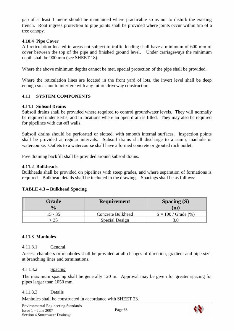
Environmental Engineering StandardsIssue 1 – June 2007Section 4 Stormwater Drainage
Page 63
gap of at least 1 metre should be maintained where practicable so as not to disturb the existingtrench. Root ingress protection to pipe joints shall be provided where joints occur within 5m of atree canopy.
4.10.4 Pipe CoverAll reticulation located in areas not subject to traffic loading shall have a minimum of 600 mm ofcover between the top of the pipe and finished ground level. Under carriageways the minimumdepth shall be 900 mm (see SHEET 18).
Where the above minimum depths cannot be met, special protection of the pipe shall be provided.
Where the reticulation lines are located in the front yard of lots, the invert level shall be deepenough so as not to interfere with any future driveway construction.
4.11 SYSTEM COMPONENTS
4.11.1 Subsoil DrainsSubsoil drains shall be provided where required to control groundwater levels. They will normallybe required under kerbs, and in locations where an open drain is filled. They may also be requiredfor pipelines with cut-off walls.
Subsoil drains should be perforated or slotted, with smooth internal surfaces. Inspection pointsshall be provided at regular intervals. Subsoil drains shall discharge to a sump, manhole orwatercourse. Outlets to a watercourse shall have a formed concrete or grouted rock outlet.
Free draining backfill shall be provided around subsoil drains.
4.11.2 BulkheadsBulkheads shall be provided on pipelines with steep grades, and where separation of formations isrequired. Bulkhead details shall be included in the drawings. Spacings shall be as follows:
TABLE 4.3 – Bulkhead Spacing
Grade%
Requirement Spacing (S)(m)
15 - 35 Concrete Bulkhead S = 100 / Grade (%)> 35 Special Design 3.0
4.11.3 Manholes
4.11.3.1 GeneralAccess chambers or manholes shall be provided at all changes of direction, gradient and pipe size,at branching lines and terminations.
4.11.3.2 SpacingThe maximum spacing shall be generally 120 m. Approval may be given for greater spacing forpipes larger than 1050 mm.
4.11.3.3 DetailsManholes shall be constructed in accordance with SHEET 23.
Environmental Engineering StandardsIssue 1 – June 2007Section 4 Stormwater Drainage
Page 64
Normally manholes will be constructed in reinforced concrete, except where aggressive siteconditions make them unsuitable.
Shallow manholes with a maximum depth of 1.2 m and maximum pipe size of 300 mm may use a600 mm diameter manhole.
Standard manholes shall have a minimum internal diameter of 1050 mm. The size and layout shallbe designed to ensure hydraulic efficiency. With larger pipes (generally larger than 600 mm), thesize of the manhole will need to be increased to accommodate the reticulation.
With pipelines with internal diameter of 1.2 m or greater, access may be approved using offset 1050mm risers factory joined to the pipeline. These may be used in conjunction with factory made mitrejoints in the pipeline for direction changes.
Connections up to 300 mm diameter may have an open cascade of up to 2.0 m deep into a manhole.Manhole steps are to be kept clear of a cascade.
Where the pipe size changes at a manhole, the soffit of inlet pipes shall be no lower than the soffitof outlet pipes unless by specific approval.
Inlet pipes shall be cut back to the inside face of the manhole and plastered to a smooth finish. Thebase is to be benched and haunched with concrete to a plaster finish to accommodate the inlet andoutlet pipes.
All chambers shall be made watertight.
4.11.4 SumpsSumps shall be provided as required to prevent the primary design flow from discharging overadjoining properties, or over footpaths. This includes surface drainage from vehicular andpedestrian accessways.
Sumps on public roads shall comply with Section 3.16.4 of this Standard.
Sumps on private accessways shall be capable of accepting the flow from the catchment area. Theminimum grate size shall be 300 x 300 mm. Where an accessway is steep, or stormwaterconnections discharge onto the accessway, standard single or double sumps as required for roads,and detailed on SHEET 22 shall be used. Sump leads shall be adequate for the catchment area, butnot less than 225 mm.
4.11.5 Inlet and Outlet StructuresAll culvert and pipeline inlets and outlets shall be provided with adequate wingwalls, headwalls,aprons and scour protection, for erosion control, fill retention around the pipeline and pipelinesupport. With larger diameter pipes where there is a danger from access to the pipes, wingwallswith safety grates shall be provided.
Inlets shall have removable debris traps and/or pits. The effects of blockage shall be considered.The design of debris traps on inlets to large pipes (>750mm) shall be to the approval of WDC. As aminimum they shall have a raked face and an access area above to permit screen clearing at times ofhigh flows. Consideration should be given in the design of such screens to health and safety risksduring maintenance operations.
Environmental Engineering StandardsIssue 1 – June 2007Section 4 Stormwater Drainage
Page 65
The appearance of inlets and outlets in relation to the riparian landscape, and effects on in-streamvalues shall be considered.
4.11.6 WaterwaysAll waterways that will be maintained by the Council shall be protected by easement or located inland in public ownership.
4.11.6.1 Constructed WaterwaysWhere waterways are constructed, they shall be designed to be stable, not prone to scour and able tobe maintained, with adequate access for maintenance machinery. Generally concrete linedwaterways will not be permitted. Designs shall be suitable to support and facilitate the movementof aquatic life. Planting adjacent to the waterways must be suitable to stabilise the banks withoutcausing a maintenance liability in the future by their presence.
4.11.6.2 Natural WaterwaysExisting natural waterways should be retained, and piping avoided as much as possible. Reservesshould be created around significant natural waterways. Where waterways have been modified, theyshould be restored and enhanced. In catchments where a comprehensive resource consent is heldfor stormwater and the waterway is not regarded as significant in drainage or ecology terms thediversion of waterways is at the discretion of WDC.
Culverting or piping of existing waterways will require specific approval of the Wastes andDrainage Manager. This will generally not be given unless special requirements meritconsideration. The layout of lots may not provide sufficient justification.
Existing vegetation to waterway banks should be maintained and protected to prevent bank scour.Removal of vegetation and replacement with engineered banks to prevent scour will not generallybe acceptable. Retention of existing trees and bush cover adjacent to waterways is encouraged.
4.11.7 ConnectionsConnections shall be provided to all new urban lots, and to rural lots where a stormwater systemwith adequate capacity is available, subject to the principles set out above.
Where stormwater reticulation is available, connections shall be made directly to stormwater mains,rather than via a kerb connection. Where this is not practicable, connections may discharge to awaterway, to a roadside kerb, or to an approved stormwater treatment/retention system.
Discharge via a kerb connection will only be permitted where the road has full kerb and channel andwhere it can be demonstrated that other properties adjacent to the road will not be compromised bythe discharge.
The minimum connection size shall be: 100 mm for each residential allotment. 150 mm for a commercial/industrial lot. The connection shall be designed to suit the potential
site coverage, and where known, the intended use of the property. The minimum connectionsize will only be suitable for small lots.
Where discharge rate controls are applied, the Council may approve alternative connection sizes.
Environmental Engineering StandardsIssue 1 – June 2007Section 4 Stormwater Drainage
Page 66
Connections shall be sited clear of obstructions and known developments and accessible formaintenance.
Direct connection of minor pipelines to major pipelines is acceptable, provided: Connection is via a suitable junction or saddle, The distance between the connection and the closest inspection point is not greater than 11 m.
Connections shall be sealed with removable caps until required. Their location shall be accuratelymeasured and shown on as-built plans.
4.11.8 Soak PitsSoak pits may be approved where a geotechnical investigation demonstrates that soils are suitablefor soakage. Refer to E1/VM1 of the Approved Document for Clause E1 of the NZBC. Soak pitsshall not be used in areas subject to instability.
4.11.9 Stormwater Detention AreasThe requirement for stormwater detention, and the design parameters shall be established as part ofthe stormwater analysis carried out by an IQP.
Stormwater detention areas shall be contained within legal boundaries of a drainage reserve. Theyshall not be included in local purpose reserves.
All weather, legal access to the area from a road shall be provided for maintenance. Hazards fromthe area shall be identified and mitigated. The requirement for fencing complying with the Fencingof Swimming Pools Act 1987 shall be established, and provided as necessary.
4.12 DESIGN
4.12.1 General RequirementsIn general, stormwater systems should be designed so that the full development will not result inany increase in discharge rates or reduced quality, compared to the pre-development situation. Thismay require on-site detention systems.
The design shall specifically cover the provision of sumps, culvert inlets etc. to ensure that thedesign surface flow can enter the system. Particular attention shall be paid to inlet assessment whenlooking at flow conditions for pipes (i.e. providing adequate head to achieve design flows).
4.12.2 Design Methods
4.12.2.1 Small Urban CatchmentsFor small urban areas, particularly infill developments with a catchment of less than 2.5 ha, theprimary design flow (post development) may be taken as 210 litres/sec/hectare for the design ofpipelines. This will be conservative for most situations, and savings may be available by usingspecific design. Consideration shall be given to secondary flow paths. A full design may berequired to establish effects on downstream reticulation and for flow mitigation measures.
4.12.2.2 Specific DesignThe design of a stormwater system not covered by the above method will require specific design.The design shall be carried out by an IQP (refer to glossary for definition), experienced in catchmentdesign.

Environmental Engineering StandardsIssue 1 – June 2007Section 4 Stormwater Drainage
Page 67
This standard does not cover the detailed methodology to be followed in the design.
NZS 4404:2004 Section 4.3.12, in conjunction with Verification Method E1 / VM1 of the ApprovedDocuments for New Zealand Building Code is an approved means of compliance. Other methods,e.g. the Procedure for Hydrological Design for Urban Stormwater Systems by the New ZealandInstitution of Engineers, or a proprietary computer model may also be approved. If a computernetwork model is used, it shall be MOUSE or a programme that produces outputs that are consistentwith MOUSE.
For large catchments with significant storage elements, specific design using unsteady flowmodelling shall be used.
APPENDIX C gives the Intensity Duration Curves and Runoff Coefficients to be used in the design,unless acceptable alternative data is provided. Acceptable alternatives include analyses of a specificsite based on information provided by NIWA, and/or verified research studies of particular soil orsite conditions.
The design shall take into account the following:
Estimation of Surface Run-off, Critical storm duration in relation to storage provisions where applicable, Rainfall Intensity and Time of Concentration, Sizing of the stormwater drainage components based on hydraulic capacity, including analysis
of full pipe and part pipe flows, Analysis of energy loss through structures (Manholes, bends, inlets etc.) Determination of water surface profiles in a stormwater drainage system, Outfall water levels, Allowance for climate change (refer Section 4.8.2).
4.12.3 Gradients and Acceptable Flow VelocitiesPipes shall be kept as steep as possible in flat areas to control silt deposition. The velocity shouldbe at least 0.6 m/s at a flow of 50% of a 2-year return period storm.
Erosion of concrete pipes should be considered where the pipe gradient is steeper than 1 in 3.
4.12.4 Outlet and Backflow EffectsOutlet design and water level conditions shall be taken into account in the design of discharges tostormwater systems and waterways.
Where stormwater discharges to tidal waters, the design shall assume a tide level of Mean HighWater Spring (MHWS)
4.12.5 Culvert DesignThe design of culverts shall consider the effects of inlet and tailwater controls. An acceptablemethod of assessing flows with inlet and outlet control is given in the Approved Documents for NewZealand Building Code, Verification Method E1 / VM1.
4.12.6 Secondary Flow PathsThe design shall include a full analysis of overland flow paths. This shall include preparation ofplans, long sections and cross sections showing design water levels for a 1% AEP storm. Where thesecondary flow path is in private property, limitations on development shall be noted.
Environmental Engineering StandardsIssue 1 – June 2007Section 4 Stormwater Drainage
Page 68
4.13 STORMWATER QUALITY CONTROLThe following summarises requirements of the Northland Regional Council in relation tostormwater quality control.
All new subdivision developments or re-developments, and all other new stormwater systems, shallas a minimum:
Incorporate stormwater runoff control measures that, where practicable, use infiltrationfacilities as the primary methods of stormwater disposal in permeable soil types, including butnot restricted to, porous pavements, grassed swales, and riparian zones,,
Limit areas of impermeable surfaces in carparking areas, driveways, roading and residentiallots,
Incorporate secondary flow paths for storm events greater than the primary design flow (1:100year flood event) ,
Retention of designated flood prone areas, Discourage piping and lining of larger drains where open channels and/or grass swales can
provide the required drainage paths, Require, as far as practicable, the retention of natural stream channels. The discharge of any stormwater should not cause the quality of the water to fall below the
water quality guidelines given in section 7.6 of the Regional Water and Soil Plan for Northland.
It is emphasised that applicants shall always refer to the Regional Council and CDPs beforecommencing the design of a new system. It is expected that all discharges should be treated in linewith the requirements of the ARC TP 10 standard.
It is noted that the District Council commenced, in 2001, a monitoring programme of the waterwaysin its urban drainage areas. Information from that monitoring will be made available to applicantsto assist them in the design of the on-site measures.
4.14 INSPECTION AND TESTING
4.14.1 Pipeline Pressure TestA pipeline pressure test will not normally be required. However the Council reserves the right torequire a low-pressure air test of the reticulation.
4.14.2 CCTV InspectionThe whole of the reticulation shall be inspected and recorded by CCTV. Inspection records shallcomply with NZWWA ‘New Zealand Pipe Inspection Manual’.
4.14.3 ManholesAll manholes shall be visually inspected to ensure the standard of construction and finishing isacceptable.
4.14.4 Marking of ConnectionsAll connections shall be sealed with an approved plug or cap, and be marked with a 100x50H4treated stake painted red, extending from invert level of the pipe to 600 mm above ground level.Exposed surfaces of manhole covers shall be painted red.
Environmental Engineering StandardsIssue 1 – June 2007Section 4 Stormwater Drainage
Page 69
4.15 COMPLETION
4.15.1 As-Built DrawingsA set of drawings and a schedule of asset information shall be submitted as per Section 1.7 of thisStandard. This shall clearly and accurately show the as-built locations and details of all stormwaterinfrastructure provided as part of the work, including any modifications made to the existing system.
Additional requirements for stormwater include:
Plans shall identify catchment and sub-catchment boundaries, watercourses, reticulation, andsecondary flow paths.
The area of catchments and sub-catchments shall be shown. Drawings shall include plans, long sections and cross sections showing design water levels for a
1% AEP storm. Where the secondary flow path is in private property, limitations ondevelopment shall be noted.
Minimum floor levels shall be specified for lots that may be affected by secondary flow paths ortidal effects.
The As Built drawings may be checked on site for accuracy on completion of the subdivisionor development. A certificate of completion for the works will not be issued until acceptable As-Built drawings have been produced.
The drawings shall identify assets that have been removed or decommissioned.
4.15.2 Operation and Maintenance ManualsFull details of all stormwater treatment facilities, and all other mechanical installations shall beprovided, including complete O & M Manuals in PDF format, plus 3 hard copies, The O&MManuals shall include:
As-built drawings, Equipment List, with make, model and serial numbers, Equipment supplier details, Maintenance schedules.
4.16 DEFECTS LIABILITYA Performance Bond will be required for the works in terms of Section 1.13 of this Standard.
4.17 DRAWINGSThe following drawings in APPENDIX A apply to this section:
SHEET 1 STANDARD DRAWING SYMBOLSSHEET 11 RECOMMENDED SERVICE LOCATIONSSHEET 12 KERB AND CHANNEL DETAILSSHEET 13 TYPICAL KERB AND SUBSOIL DRAIN DETAILSSHEET 18 PIPE BEDDING AND BACKFILLSHEET 19 PIPE PROTECTION AND BULKHEADSSHEET 20 INLET AND OUTLET STRUCTURESSHEET 21 LAMPHOLES, STORMWATER AND SEWER CONNECTIONSSHEET 22 SUMP DETAILSSHEET 23 STANDARD PRECAST MANHOLES

Environmental Engineering StandardsIssue 1 – June 2007Section 5 Wastewater
Page 71
5. WASTEWATER RETICULATION AND TREATMENT
5.1 GENERAL REQUIREMENTSThis Section covers the requirements for wastewater disposal, and the design and construction ofpublic wastewater reticulation systems, including associated pump stations and rising mains.
This Standard covers conventional reticulation. Alternative reticulation systems (e.g. EDS orSuction systems) shall be subject to specific approval and agreement on design standards.
Where a public wastewater scheme is available, connection to it will be required. Where an existingwastewater disposal scheme is not available, an alternative method of disposal must be available.This will normally be by on-site treatment and disposal.
5.2 REFERENCED DOCUMENTSThe following documents shall be read in conjunction with this section of these standards:
Whangarei District Council Proposed District Plan (WDC) Regional Soil and Water Plan for Northland (NRC) Regional Coastal Plan for Northland (NRC) WDC Coastal Structure Plan – Slope instability Potential and Effluent Disposal Potential,
Oakura to Langs Beach. Whangarei District Council Wastewater Asset Management Plan, WDC Wastewater Pumping Stations Electrical Engineering Systems.
The above documents will be added to from time to time as further investigations and reports arecompleted. The applicant is advised to obtain information from Council on any relevant documentsapplicable to the site.
Where aspects of the design are not covered by this section or the above Council documents thefollowing standards may be referenced. Adoption of any practises outside of the Councildocumentation shall first be approved by the Council.
NZS 4404:2004 Land Development and Subdivision Engineering WSA 02 – Sewerage Code of Australia WSA 04 – Sewage Pumping Code of Australia Guide for Safety with Underground Services – Occupational Health and Safety.
The most up to date of these publications shall supersede any conflicting requirements of olderdocuments.
5.3 SUBMISSION OF APPLICATION
5.3.1 Supporting Information and CalculationsThe application shall include supporting information and calculations that demonstrate that: the existing wastewater reticulation and treatment system that the development will connect to
is adequate to serve the proposed development, the proposed reticulation is adequate to serve the proposed development, and where required by
the Council, the potential upstream catchment.
Environmental Engineering StandardsIssue 1 – June 2007Section 5 Wastewater
Page 72
Conventional gravity reticulation with up to 150 mm pipelines, not requiring specific hydraulicdesign, and strictly complying with the provisions of this standard may be designed by a suitablyqualified & experienced person.
All other systems, including gravity pipelines serving more than 250 lots, pump stations, pressuremains, above-ground structures, pipes where the minimum cover is not achieved, siphons etc. shallbe designed by an Independent Qualified Person (IQP) who shall provide a design certificateidentifying the design standards used, and certifying that the design complies with these standards.
The design shall include: Pipe sizes, material, and layout of the reticulation, Hydraulic design, including providing adequate capacity and self-cleaning velocity, Service connection locations to serve the buildable area with a gravity connection, Design of pump stations and rising mains. Preparation of plans and specifications.
5.3.2 Design Drawings and SpecificationsDesign drawings complying with the requirements of Sections 1.5 and 1.6 shall be provided forapproval.
5.3.3 Approval of DesignThe drawings and calculations will be will be reviewed by the Wastewater and Drainage ServicesManager or his/her representative. The completed form and the drawings showing any alterationsshall be returned to the developers representative. If adjustments to the design are required a newset of amended drawings shall be submitted to the Council prior to approval being granted. Onlydrawings stamped and signed by the Wastewater and Drainage Services Manager shall be deemedapproved drawings. Unless specifically stated otherwise, the approval of drawings does notsupersede the requirements or obligations of these standards.
5.4 WASTEWATER TREATMENT AND DISPOSAL
5.4.1 Connection to Existing Wastewater SchemeAll lots within the ‘Area of Benefit’ of a sewerage scheme shall be provided with a gravityconnection to the Council system unless the Council confirms in writing that a connection isunwarranted, unavailable or unsuitable. Where properties are adjacent to an area of benefit, Councilmay approve a connection, or require that a connection to the system be provided.
5.4.2 Alternative Treatment and Disposal Options
5.4.2.1 Individual On-Site Treatment and DisposalWhere a connection to an existing scheme is not available, the lot size complies with minimumrequirements in the District Plan for on-site disposal of wastewater, and there are no factors thatmay preclude or limit its use, on-site disposal will normally be approved.
If the lot size is less than 2000 m3, or the available area for disposal is limited due to thetopography, high ground-water table or hazards such as flooding or instability, the applicant shalldemonstrate for each lot that:
the site is suitable for the disposal system proposed, and adequate area including reserve area is available.
Environmental Engineering StandardsIssue 1 – June 2007Section 5 Wastewater
Page 73
This will require an investigation carried out by an IQP, using the Site-and-Soil EvaluationProcedures of AS/NZS 1547:2000, and the performance requirements in Northland RegionalCouncil Regional Plans.
Reference should be made to the WDC Hazard Plans (e.g. Coastal Structure Plan – Slope instabilityPotential and Effluent Disposal Potential, Oakura to Langs Beach (Tonkin and Taylor 2005)). Therequirements regarding soil suitability for effluent disposal and lot sizes will be the basis forevaluation of the suitability of a site for on-site treatment and disposal.
5.4.2.2 Provision of New Treatment and Disposal SchemeCouncil may approve the provision of a new wastewater scheme to serve a development, subject tothe following: The new system has obtained all required Resource Consents from the Northland Regional
Council, Adequate provisions for operation and maintenance of the system are in place.
Council may agree to take over future responsibility for the management and maintenance of a newsystem that serves more than 15 households. Specific negotiation will be required to determine thefinancial, technical and legal aspects of such an agreement.
In general the following will also be required: All parts of the new system comply with this standard, except as specifically agreed, Building consent and all associated code-compliance certificates are obtained, As Built drawings, Producer Statements from the designer and construction supervisors, and a
management plan approved by the Northland Regional Council are provided, Sufficient land area is designated to accommodate a treatment and disposal system with capacity
for flows from the ultimate catchment development;
5.4.3 DisconnectionsCouncil approval is required for disconnection from the wastewater network to ensure that thedisconnection is carried out appropriately and the old connection blanked off in a way that preventsinfiltration entering the network and/or leaks occurring from the connection location.
A Council inspecting officer shall inspect all disconnections before back-filling takes place.
5.5 CONSENTSAll Building Consents and Resource Consents for the wastewater system shall be obtained,including consents for stream crossings, pump station discharges etc.
5.6 LEVEL OF SERVICE
5.6.1 Design LifeThe asset life of wastewater supply systems shall not be less than 100 years. The asset life ofcomponents of the systems, e.g. pumps, valves etc shall be noted in the application.
5.6.2 Service RequirementsWhere a wastewater system is available, or where a system is to be provided as part of a subdivisionor development, it shall have adequate capacity to service the full catchment, long service life, a lowlevel of infiltration, and resistance to entry of tree roots.

Environmental Engineering StandardsIssue 1 – June 2007Section 5 Wastewater
Page 74
5.6.3 Capacity and Future System ExpansionThe development shall be reticulated with a piped system adequate to transport the design flowwithout surcharging.
The wastewater reticulation shall be constructed to the upstream boundaries of the approveddevelopment at the applicants expense and shall be capable of serving the entire subdivision ordevelopment and any undeveloped land beyond, when that land is developed to its ultimatedevelopment intensity.
Where future upstream development is possible, the depth and alignment of the reticulation shall besuitable for such development.
5.6.4 Infiltration MinimisationThe reticulation shall be designed, detailed, constructed and tested to ensure that there is zeropipeline infiltration at commissioning and a low level of infiltration/exfiltration over the life of thesystem. Testing shall include all components of the system, including manholes.
The use of sealed maintenance and inspection structures to replace manholes, in accordance withthis standard is required.
5.6.5 Council Design InputThe Council shall have the right to specify the diameters and classes of pipes to be used for allreticulation within the subdivision or development, and to specify connection points and reticulationalignment. It will provide on request details of the existing reticulation for design purposes. Wherenecessary, Council will investigate the capacity of the downstream wastewater reticulation andtreatment facilities to determine their adequacy, at the applicant’s expense.
5.7 PIPE SELECTION
5.7.1 Pipe Materials and ClassStandard approved pipe materials are given in Table 5.1. Other materials shall only be used withthe written approval of the Wastewater and Drainage Services Manager.
Pressure pipelines (Rising Mains) shall meet the material, construction and testing requirements ofPrincipal Water Mains, as set out in Section 6 of this Standard. For PE pipes, the internal beadformed by welding shall be removed.
Blue coloured pipes shall not be used for sewer pipelines.
5.7.2 Pipe BridgesPipe bridges shall be specifically designed for the particular environment. Piles may be concrete ortimber. The developer is responsible for obtaining all building consents and resource consents.Pipelines across bridges (normally rising mains) will normally use Ductile Iron or coated steel pipes.
Timber piles shall be H6 treated. No cutting, notching or boring after treatment is permitted in areasin contact with soil or water. Cut or bored areas shall be resealed using a suitable preservativetreatment.
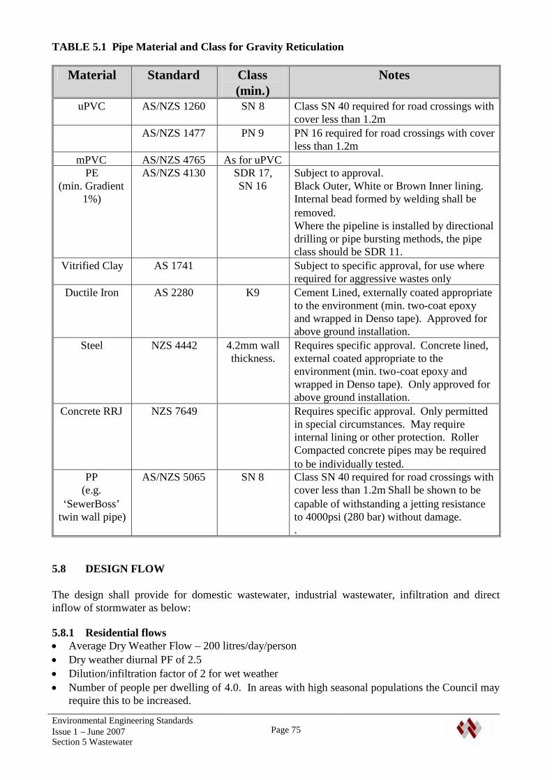
Environmental Engineering StandardsIssue 1 – June 2007Section 5 Wastewater
Page 75
TABLE 5.1 Pipe Material and Class for Gravity Reticulation
Material Standard Class(min.)
Notes
uPVC AS/NZS 1260 SN 8 Class SN 40 required for road crossings withcover less than 1.2m
AS/NZS 1477 PN 9 PN 16 required for road crossings with coverless than 1.2m
mPVC AS/NZS 4765 As for uPVCPE
(min. Gradient1%)
AS/NZS 4130 SDR 17,SN 16
Subject to approval.Black Outer, White or Brown Inner lining.Internal bead formed by welding shall beremoved.Where the pipeline is installed by directionaldrilling or pipe bursting methods, the pipeclass should be SDR 11.
Vitrified Clay AS 1741 Subject to specific approval, for use whererequired for aggressive wastes only
Ductile Iron AS 2280 K9 Cement Lined, externally coated appropriateto the environment (min. two-coat epoxyand wrapped in Denso tape). Approved forabove ground installation.
Steel NZS 4442 4.2mm wallthickness.
Requires specific approval. Concrete lined,external coated appropriate to theenvironment (min. two-coat epoxy andwrapped in Denso tape). Only approved forabove ground installation.
Concrete RRJ NZS 7649 Requires specific approval. Only permittedin special circumstances. May requireinternal lining or other protection. RollerCompacted concrete pipes may be requiredto be individually tested.
PP(e.g.
‘SewerBoss’twin wall pipe)
AS/NZS 5065 SN 8 Class SN 40 required for road crossings withcover less than 1.2m Shall be shown to becapable of withstanding a jetting resistanceto 4000psi (280 bar) without damage..
5.8 DESIGN FLOW
The design shall provide for domestic wastewater, industrial wastewater, infiltration and directinflow of stormwater as below:
5.8.1 Residential flows Average Dry Weather Flow – 200 litres/day/person Dry weather diurnal PF of 2.5 Dilution/infiltration factor of 2 for wet weather Number of people per dwelling of 4.0. In areas with high seasonal populations the Council may
require this to be increased.
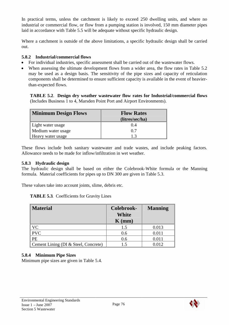
Environmental Engineering StandardsIssue 1 – June 2007Section 5 Wastewater
Page 76
In practical terms, unless the catchment is likely to exceed 250 dwelling units, and where noindustrial or commercial flow, or flow from a pumping station is involved, 150 mm diameter pipeslaid in accordance with Table 5.5 will be adequate without specific hydraulic design.
Where a catchment is outside of the above limitations, a specific hydraulic design shall be carriedout.
5.8.2 Industrial/commercial flows For individual industries, specific assessment shall be carried out of the wastewater flows. When assessing the ultimate development flows from a wider area, the flow rates in Table 5.2
may be used as a design basis. The sensitivity of the pipe sizes and capacity of reticulationcomponents shall be determined to ensure sufficient capacity is available in the event of heavier-than-expected flows.
TABLE 5.2. Design dry weather wastewater flow rates for Industrial/commercial flows(Includes Business 1 to 4, Marsden Point Port and Airport Environments).
Minimum Design Flows Flow Rates(litres/sec/ha)
Light water usageMedium water usageHeavy water usage
0.40.71.3
These flows include both sanitary wastewater and trade wastes, and include peaking factors.Allowance needs to be made for inflow/infiltration in wet weather.
5.8.3 Hydraulic designThe hydraulic design shall be based on either the Colebrook-White formula or the Manningformula. Material coefficients for pipes up to DN 300 are given in Table 5.3.
These values take into account joints, slime, debris etc.
TABLE 5.3. Coefficients for Gravity Lines
Material Colebrook-White
K (mm)
Manning
VC 1.5 0.013PVC 0.6 0.011PE 0.6 0.011Cement Lining (DI & Steel, Concrete) 1.5 0.012
5.8.4 Minimum Pipe SizesMinimum pipe sizes are given in Table 5.4.
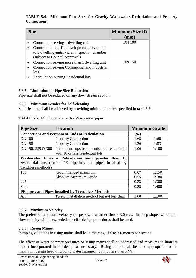
Environmental Engineering StandardsIssue 1 – June 2007Section 5 Wastewater
Page 77
TABLE 5.4. Minimum Pipe Sizes for Gravity Wastewater Reticulation and PropertyConnections
Pipe Minimum Size ID(mm)
Connection serving 1 dwelling unit Connection to in-fill development, serving up
to 3 dwelling units, via an inspection chamber(subject to Council Approval)
DN 100
Connection serving more than 1 dwelling unit Connection serving Commercial and Industrial
lots Reticulation serving Residential lots
DN 150
5.8.5 Limitation on Pipe Size ReductionPipe size shall not be reduced on any downstream section.
5.8.6 Minimum Grades for Self-cleaningSelf-cleaning shall be achieved by providing minimum grades specified in table 5.5.
TABLE 5.5. Minimum Grades for Wastewater pipes
Pipe Size Location Minimum GradeConnections and Permanent Ends of Reticulation (%)DN 100 Property Connection 1.65 1:60DN 150 Property Connection 1.20 1:83DN 150, 225 & 300 Permanent upstream ends of reticulation
with 10 or less residential lots1.00 1:100
Wastewater Pipes – Reticulation with greater than 10residential lots (except PE Pipelines and pipes installed bytrenchless methods)150 Recommended minimum
Absolute Minimum Grade0.670.55
1:1501:180
225 0.33 1:300300 0.25 1:400PE pipes, and Pipes Installed by Trenchless MethodsAll To suit installation method but not less than 1.00 1:100
5.8.7 Maximum VelocityThe preferred maximum velocity for peak wet weather flow s 3.0 m/s. In steep slopes where thisflow velocity will be exceeded, specific design procedures shall be used.
5.8.8 Rising MainsPumping velocities in rising mains shall be in the range 1.0 to 2.0 metres per second.
The effect of water hammer pressures on rising mains shall be addressed and measures to limit itsimpact incorporated in the design as necessary. Rising mains shall be rated appropriate to themaximum design head (including water hammer), but not less than PN9.
Environmental Engineering StandardsIssue 1 – June 2007Section 5 Wastewater
Page 78
The design shall include the requirement for air valves, including odour considerations.
5.9 LAYOUT OF RETICULATION
5.9.1 General
5.9.1.1 Gravity PipelinesGravity pipelines may be located within roads, public reserves and private property.
Wherever possible, reticulation is to be located in the road berms. Crossings of roads, railway lines,creeks, drains and underground services shall be at right angles as far as possible.
In private property and other areas where development or building may occur, pipes shall be locatedclear of potential building sites and existing or proposed engineering features. Where practical,pipes shall run parallel to boundaries with an offset from the boundary between 1.0 m and 1.5 m..
Where possible, pipes shall be sited outside of the zone of influence of the foundations of existingstructures. Where this is not possible, the pipe and structure shall be protected to details approvedby the Council. The design shall include protection of the pipeline and structure, and maintenanceaccess for the pipeline.
No structure shall be erected over any buried public sewer or stormwater system without priorwritten approval of Council’s Wastes and Drainage Manager.
5.9.1.2 Curved PipelinesWhere practicable and economic, pipelines should be constructed in straight horizontal and verticalalignment between maintenance structures.
Subject to specific design, close control of installation to maintain grades and alignment, andaccurate as-built plans, curved pipelines may be approved. Approval will normally be given wherepipelines follow curved street alignments, or where there will be savings in life-cycle costs.
5.9.1.3 Maintenance StructuresAll manhole and other maintenance structures shall be kept clear of boundaries, and wherepracticable, outside of carriageways and footpaths.
They shall be located as far as possible: Where long term, safe access is available, Clear of floodways, stormwater detention areas, stormwater secondary flow paths and inter-tidal
regions.
A minimum clearance of 1.0 m from openings should be provided around maintenance structures,for maintenance purposes.
The top of manholes and maintenance structures in areas subject to flooding shall be 300 mm abovethe 1 in 100 year flood level. Where this is not practicable, watertight, bolt-down covers shall beused, and all manhole components tied together.
Easements in favour of Council may be required by the Council to allow vehicle access tomaintenance points of the reticulation.
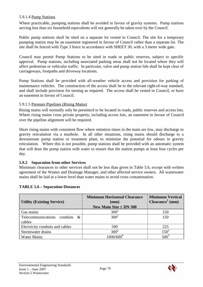
Environmental Engineering StandardsIssue 1 – June 2007Section 5 Wastewater
Page 79
5.9.1.4 Pump StationsWhere practicable, pumping stations shall be avoided in favour of gravity systems. Pump stationsserving less than six household equivalents will not generally be taken over by the Council.
Public pump stations shall be sited on a separate lot vested in Council. The site for a temporarypumping station may be an easement registered in favour of Council rather than a separate lot. Thesite shall be fenced with Type 3 fence in accordance with SHEET 30, with a 3 metre wide gate.
Council may permit Pump Stations to be sited in roads or public reserves, subject to specificapproval. Pump stations, including associated parking areas shall not be located where they willaffect pedestrian or vehicular traffic. In particular, valve and pump station lids shall be kept clear ofcarriageways, footpaths and driveway locations.
Pump Stations shall be provided with all-weather vehicle access and provision for parking ofmaintenance vehicles. The construction of the access shall be to the relevant right-of-way standard,and shall include provision for turning as required. The access shall be vested in Council, or havean easement in favour of Council.
5.9.1.5 Pressure Pipelines (Rising Mains)Rising mains will normally only be permitted to be located in roads, public reserves and access lots.Where rising mains cross private property, including access lots, an easement in favour of Councilover the pipeline alignment will be required.
Short rising mains with consistent flow where retention times in the main are low, may discharge togravity reticulation via a manhole. In all other situations, rising mains should discharge to adownstream pump station or treatment plant, to minimise the potential for odours in gravityreticulation. Where this is not possible, pump stations shall be provided with an automatic systemthat will dose the pump station with water to ensure that the station pumps at least four cycles perday.
5.9.2 Separation from other ServicesMinimum clearances to other services shall not be less than given in Table 5.6, except with writtenagreement of the Wastes and Drainage Manager, and other affected service owners. All wastewatermains shall be laid at a lower level than water mains to avoid cross contamination.
TABLE 5.6 – Separation Distances
Utility (Existing Service)Minimum Horizontal Clearance
(mm)New Main Size DN 300
Minimum VerticalClearance1 (mm)
Gas mains 3002 150Telecommunications conduits &cables
3002 150
Electricity conduits and cables 500 225Stormwater drains 3002 1503
Water Mains 1000/6004 5003
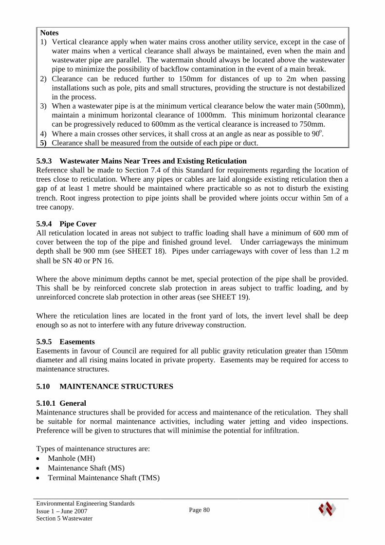
Environmental Engineering StandardsIssue 1 – June 2007Section 5 Wastewater
Page 80
Notes1) Vertical clearance apply when water mains cross another utility service, except in the case of
water mains when a vertical clearance shall always be maintained, even when the main andwastewater pipe are parallel. The watermain should always be located above the wastewaterpipe to minimize the possibility of backflow contamination in the event of a main break.
2) Clearance can be reduced further to 150mm for distances of up to 2m when passinginstallations such as pole, pits and small structures, providing the structure is not destabilizedin the process.
3) When a wastewater pipe is at the minimum vertical clearance below the water main (500mm),maintain a minimum horizontal clearance of 1000mm. This minimum horizontal clearancecan be progressively reduced to 600mm as the vertical clearance is increased to 750mm.
4) Where a main crosses other services, it shall cross at an angle as near as possible to 90o.5) Clearance shall be measured from the outside of each pipe or duct.
5.9.3 Wastewater Mains Near Trees and Existing ReticulationReference shall be made to Section 7.4 of this Standard for requirements regarding the location oftrees close to reticulation. Where any pipes or cables are laid alongside existing reticulation then agap of at least 1 metre should be maintained where practicable so as not to disturb the existingtrench. Root ingress protection to pipe joints shall be provided where joints occur within 5m of atree canopy.
5.9.4 Pipe CoverAll reticulation located in areas not subject to traffic loading shall have a minimum of 600 mm ofcover between the top of the pipe and finished ground level. Under carriageways the minimumdepth shall be 900 mm (see SHEET 18). Pipes under carriageways with cover of less than 1.2 mshall be SN 40 or PN 16.
Where the above minimum depths cannot be met, special protection of the pipe shall be provided.This shall be by reinforced concrete slab protection in areas subject to traffic loading, and byunreinforced concrete slab protection in other areas (see SHEET 19).
Where the reticulation lines are located in the front yard of lots, the invert level shall be deepenough so as not to interfere with any future driveway construction.
5.9.5 EasementsEasements in favour of Council are required for all public gravity reticulation greater than 150mmdiameter and all rising mains located in private property. Easements may be required for access tomaintenance structures.
5.10 MAINTENANCE STRUCTURES
5.10.1 GeneralMaintenance structures shall be provided for access and maintenance of the reticulation. They shallbe suitable for normal maintenance activities, including water jetting and video inspections.Preference will be given to structures that will minimise the potential for infiltration.
Types of maintenance structures are: Manhole (MH) Maintenance Shaft (MS) Terminal Maintenance Shaft (TMS)
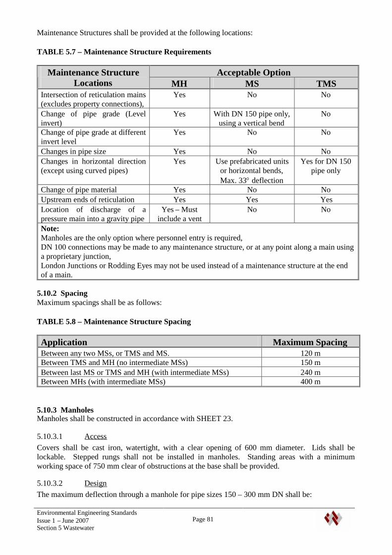
Environmental Engineering StandardsIssue 1 – June 2007Section 5 Wastewater
Page 81
Maintenance Structures shall be provided at the following locations:
TABLE 5.7 – Maintenance Structure Requirements
Acceptable OptionMaintenance StructureLocations MH MS TMS
Intersection of reticulation mains(excludes property connections),
Yes No No
Change of pipe grade (Levelinvert)
Yes With DN 150 pipe only,using a vertical bend
No
Change of pipe grade at differentinvert level
Yes No No
Changes in pipe size Yes No NoChanges in horizontal direction(except using curved pipes)
Yes Use prefabricated unitsor horizontal bends,Max. 33deflection
Yes for DN 150pipe only
Change of pipe material Yes No NoUpstream ends of reticulation Yes Yes YesLocation of discharge of apressure main into a gravity pipe
Yes – Mustinclude a vent
No No
Note:Manholes are the only option where personnel entry is required,DN 100 connections may be made to any maintenance structure, or at any point along a main usinga proprietary junction,London Junctions or Rodding Eyes may not be used instead of a maintenance structure at the endof a main.
5.10.2 SpacingMaximum spacings shall be as follows:
TABLE 5.8 – Maintenance Structure Spacing
Application Maximum SpacingBetween any two MSs, or TMS and MS. 120 mBetween TMS and MH (no intermediate MSs) 150 mBetween last MS or TMS and MH (with intermediate MSs) 240 mBetween MHs (with intermediate MSs) 400 m
5.10.3 ManholesManholes shall be constructed in accordance with SHEET 23.
5.10.3.1 AccessCovers shall be cast iron, watertight, with a clear opening of 600 mm diameter. Lids shall belockable. Stepped rungs shall not be installed in manholes. Standing areas with a minimumworking space of 750 mm clear of obstructions at the base shall be provided.
5.10.3.2 DesignThe maximum deflection through a manhole for pipe sizes 150 – 300 mm DN shall be:
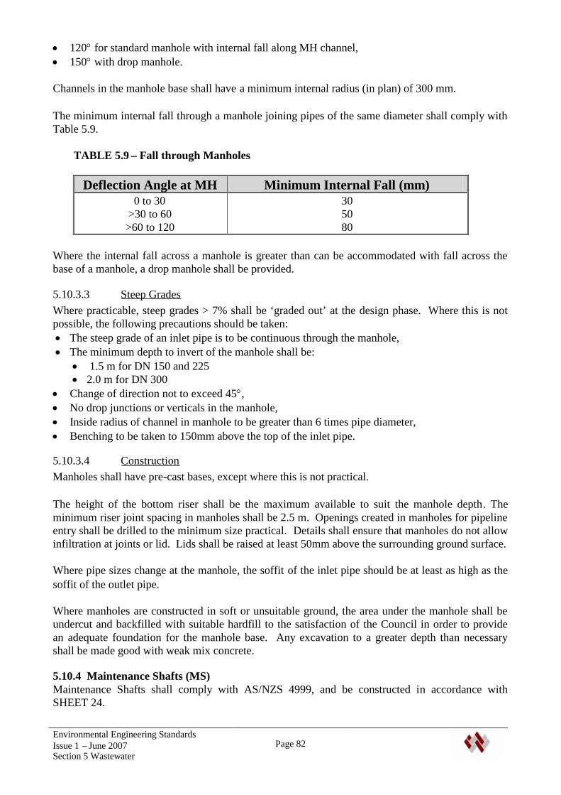
Environmental Engineering StandardsIssue 1 – June 2007Section 5 Wastewater
Page 82
120for standard manhole with internal fall along MH channel, 150with drop manhole.
Channels in the manhole base shall have a minimum internal radius (in plan) of 300 mm.
The minimum internal fall through a manhole joining pipes of the same diameter shall comply withTable 5.9.
TABLE 5.9 – Fall through Manholes
Deflection Angle at MH Minimum Internal Fall (mm)0 to 30
>30 to 60>60 to 120
305080
Where the internal fall across a manhole is greater than can be accommodated with fall across thebase of a manhole, a drop manhole shall be provided.
5.10.3.3 Steep GradesWhere practicable, steep grades > 7% shall be ‘graded out’ at the design phase. Where this is notpossible, the following precautions should be taken: The steep grade of an inlet pipe is to be continuous through the manhole, The minimum depth to invert of the manhole shall be:
1.5 m for DN 150 and 225 2.0 m for DN 300
Change of direction not to exceed 45, No drop junctions or verticals in the manhole, Inside radius of channel in manhole to be greater than 6 times pipe diameter, Benching to be taken to 150mm above the top of the inlet pipe.
5.10.3.4 ConstructionManholes shall have pre-cast bases, except where this is not practical.
The height of the bottom riser shall be the maximum available to suit the manhole depth. Theminimum riser joint spacing in manholes shall be 2.5 m. Openings created in manholes for pipelineentry shall be drilled to the minimum size practical. Details shall ensure that manholes do not allowinfiltration at joints or lid. Lids shall be raised at least 50mm above the surrounding ground surface.
Where pipe sizes change at the manhole, the soffit of the inlet pipe should be at least as high as thesoffit of the outlet pipe.
Where manholes are constructed in soft or unsuitable ground, the area under the manhole shall beundercut and backfilled with suitable hardfill to the satisfaction of the Council in order to providean adequate foundation for the manhole base. Any excavation to a greater depth than necessaryshall be made good with weak mix concrete.
5.10.4 Maintenance Shafts (MS)Maintenance Shafts shall comply with AS/NZS 4999, and be constructed in accordance withSHEET 24.

Environmental Engineering StandardsIssue 1 – June 2007Section 5 Wastewater
Page 83
Maintenance shafts shall be used on DN 150 and DN 225 pipes where access below ground will notbe required, subject to the restrictions in Table 5.7.
The maximum depth of a maintenance shaft shall be within the allowable depth of the pipeline andMS, but not more than 3.6 m.
The deviation of the riser shaft from vertical shall not exceed 300 mm, measured at the surface. Atchanges in grade, the MS should be located on the pipe with flatter gradient.
Directional and gradient changes may be made as follows: Using close-coupled bends immediately adjacent to the MS. The maximum horizontal deviation
shall be 33. Using specially manufactured MS units to suit design requirements. The maximum horizontal
deviation shall be 90.
Maintenance Shafts shall not be located in carriageways or heavily trafficked areas.
Maintenance shafts shall have sealed, removable access covers, with a separate cast iron manholecover and frame set in a concrete surround at ground level.
5.10.5 Terminal Maintenance Shafts (TMS)Terminal Maintenance Shafts may be used as terminating structures on DN 150 and DN 225 pipeswhere access below ground will not be required, subject to the restrictions in Table 5.7.
The maximum depth of a TMS shall be within the allowable depth of the pipeline and TMS, but notmore than 3.6 m.
The deviation of the riser shaft from vertical shall not exceed 300 mm, measured at the surface.
Up to two property connections may discharge directly to the riser shaft. Where a propertyconnection is directly ahead of the terminal maintenance structure, a MS may be used instead of aTMS, with a reducer immediately upstream of the MS to accept the connection.
Terminal Maintenance Shafts shall not be located in carriageways or heavily trafficked areas.
Maintenance shafts shall have sealed, removable access covers, with a separate cast iron manholecover and frame set in a concrete surround at ground level.
5.10.6 ConnectionsA 100 mm diameter service connection shall be provided for each residential allotment. The size ofa connection for a commercial/industrial lot shall be designed to suit the intended use. Connectionsshall be sited clear of obstructions and known developments and accessible for maintenance.
Connection locations and details shall be as per SHEET 21.
Connections shall be positioned at sufficient depth to enable the entire buildable area of the propertyto be served, allowing for allowable minimum grades and cover provisions in private foul waterdrains. The depth of the connection should not be less than 600 mm and generally not exceed 1500mm. Exemptions or variations will require specific Council approval.
Environmental Engineering StandardsIssue 1 – June 2007Section 5 Wastewater
Page 84
A connection shall not cross more than one lot boundary. To achieve this, a 150 mm (min.) branchsewer with a TMS may be used. This condition may be relaxed for minor “infill” development totake account of the layout of existing reticulation at the discretion of Council.
Where an existing or proposed sewer is more than 4.5 m deep, connections shall be made to ashallower branch sewer laid from a manhole on the deep sewer.
5.10.7 MarkingA detection tape shall be laid directly above all new sewers and rising mains. The tape shall have“sewerage” written on it in white, be located at a depth of between 200 and 250mm below thefinished surface level and contain sufficient metal to be detectable from the surface by a standardmetal detector.
5.11 PUMP STATIONS
5.11.1 General Requirements
Sewage Pumping Stations and rising mains shall be designed by an IQP. The design shall besubject to the Engineer’s specific approval.
Except where site conditions or specific design requirements preclude their use, Modular PackagePump Stations constructed of GRP or PE, complying with these standards shall be used. A list ofapproved designs is available from the Council. The use of alternative types including individuallyconstructed pump stations is subject to specific approval.
Flygt ‘TOPS’ pump station bases shall be used in pump stations.
Electrical and control systems shall strictly comply with the ‘WDC Wastewater Pumping StationsElectrical Engineering Systems’ Standard.
Pump Stations shall meet the following general requirements:
1. The pump station shall consist of an underground pump well, a separate valve chamber that candrain into the pump chamber, emergency storage, a water supply and electrical control cabinet.The station shall be designed for all imposed loads, including floatation.
2. Pump stations are to be designed and constructed to ensure that no stormwater enters, eitherthrough the wall or the roof and lid. The lids and the electrical control cabinet are to be aminimum of 100mm above the general ground level, with the surrounding ground graded awayfrom the station. In areas subject to flooding the top surface shall be 300 mm above the 1 in 100year flood level.
3. Pump and Valve chambers shall have sealed, lockable lids that can be readily opened by oneperson. Lid details shall comply with ‘Manukau City Council’ details (ref. ManukauEngineering Quality Standards) unless otherwise approved. Openings shall be a minimum of600x600. Pump chamber lids shall be provided with stainless steel safety grids with a grid sizeof 100 x 100 mm. Where a pump station is within 50 m of the boundary of a residentialdwelling or accommodation unit, lids shall be insulated.
4. All lifting chains, guide rails, fittings, connections, nuts, bolts etc in the pump station shall be316 Stainless Steel,
5. Pump chamber pipework shall be Ductile Iron with a two-coat epoxy coating. For smalldiameter pipework where DI is not available, stainless steel pipework shall be used.
Environmental Engineering StandardsIssue 1 – June 2007Section 5 Wastewater
Page 85
6. Concrete in pump stations shall be suitable for sewer pump stations, and shall be lined with anepoxy or similar lining. The concrete strength, admixtures and lining specification shall besupplied.
7. Pumps shall be “Flygt” 3 phase submersible type design, located on guide rails. Specificapproval by the Waste and Drainage Manager will be required for alternative pump types.
8. The preferred impellor type where the rising main size is 90 mm PE or greater is an Open Selfcleaning channel impeller i.e. Flygt ‘N’ Pump or equivalent. Shrouded single or multi-channelimpellers e.g. Flygt ‘C’ pumps, shall be capable of passing a 75mm diameter solid. For a risingmain size of less than 90 mm PE pipe, grinder cutter pumps e.g. Flygt ‘M’ pumps shall be used.
9. There shall be a minimum of two pumps (duty and standby) in all pump stations, with automaticchangeover of the pumps if the duty pump blocks or breaks down.
10. Access to pump stations shall be suitable for vehicles with a lifting gantry to install or removepumps and equipment. Where this is not possible, the wet well shall be provided with a suitablelifting arm or gantry for servicing the pumps.
11. Float cables and lifting chains shall have hook plates.12. Non-return and isolating valves for each pump shall be located in the valve chamber. The
isolating valve shall be a resilient seated gate valve complying with AS/NZS 2638.2 (anti-clockwise closing) installed downstream of the non-return valve. Non-return valves shall beball-valves with full-bore opening or swing check valves with external handles.
13. The capacity of the wet-well between start and stop levels shall be such as to limit pump startsto no more than fifteen per hour.
14. Pump chambers shall have a single inlet pipe, from an upstream ‘satellite’ manhole.15. Pump Stations shall have emergency storage in case of mechanical or electrical failure or
blockage of the pumps or rising main. The storage must be located at such a level as to preventoverflow from any manholes, gully traps, pump station lids or any other outlet from the system.Storage tanks shall be provided with a lockable, hinged, water tight lid with a minimum openingof 600x600, and able to be opened by one person by hand.
16. All pump stations shall have an approved and controlled overflow system that discharges insuch a manner to ensure maximum storage is used prior to discharge. Overflows shall bescreened.
17. All pump stations shall be reviewed for the potential for odours, and the effects of odours onadjacent dwellings. Odour mitigation shall be provided appropriate to the risk. Wet wells shallbe fan-forced ventilated to provide a minimum of four air changes per hour, with a vent stack.
18. The electrical supply shall be underground,19. Lighting shall be provided to illuminate the wet well covers and control cabinet.20. Suitable low maintenance landscaping shall be provided on the pump station site around the wet
well area.21. A standard 1800mm high three rail wooden perimeter fence or approved alternative shall be
provided.22. Pump stations shall be provided with an automatic wet well cleaning system,,23. An Operating and Maintenance Manual shall be provided that covers all aspects of the design
and operation of the stations including: Design calculations, including pipe and fitting head-loss assumptions and pump curves, A plan of the design catchment, As Built drawings including circuit diagrams and switch locations, Pump details, pump duty information, float switch levels, Contingency measures for emergency overflows, Operation and maintenance procedures, Other relevant data and information.
Environmental Engineering StandardsIssue 1 – June 2007Section 5 Wastewater
Page 86
24. Pump stations shall be tested and commissioned in the presence of Council strictly inaccordance with the ‘WDC Wastewater Pumping Stations Electrical Engineering Systems’Standard.
5.11.2 Compliance with the NRC Regional Water and Soil Plan for NorthlandWhere a pump station is required, the applicant shall obtain all Resource Consents for itsinstallation and use.
Pump Stations shall strictly comply with the requirements for a Controlled activity in the Rules forSewage Discharges in the Regional Water and Soil Plan, as follows.
15.2 Controlled ActivitiesThe unplanned discharge of raw sewage from a sewage pump station orcontributing pipe network onto or into land or into water is a controlledactivity provided that:
a) Each sewage pump station in the sewerage system has an automatic control and alarmsystem that provides:
i. Immediate notification of pump failure;ii. Automatic switching to a standby pump;iii. Immediate notification of station failure to pump sewage;iv. Notification when a system overflow is imminent, where imminent is not less than
five minutes; andv. Power supply backup for the alarm system.
b) Each sewage pumping station has at least one dedicated standby pump that will activatein the event of failure of the duty pump(s). The capacity of the standby pump(s) shall beat least equal to that of the largest pump in the station.
c) The sewage pump station has a storage capacity of not less than 12 hours (based on theaverage dry weather flow) to reduce the frequency of overflows of sewage. For thepurpose of determining compliance with condition (c) the storage volume provided shallbe that calculated from the pump high level alarm point to the lowest point at which anoverflow will occur, including any storage provided in the upstream reticulation.
Note that where particular constraints exist – e.g. a sensitive receiving environment such as abathing area or marine farm, the Consent Conditions may require a greater storage capacity.
5.11.3 Hydraulic DesignEach pump shall : provide pumping velocities in the rising main in the range 1.0 to 2.0 metres per second; pump stations and rising mains shall be designed to provide for the peak wet weather flow from
the ultimate catchment development, without utilising the required emergency storage capacity.
Material coefficients shall use the values given in Section 5.8.3 (old pipes). The design shall bechecked for coefficients appropriate for new pipes.
Where possible, the rising main should be sized, and the pump controlled, such that the volume ofthe rising main is pumped at least once each day, preferably each pump cycle. If there is insufficientinflow into the pump station to achieve this, then measures shall be incorporated into the design tocontrol odours at the outlet of the rising main. These may include:
Environmental Engineering StandardsIssue 1 – June 2007Section 5 Wastewater
Page 87
Regular flushing of the main with clean water, to clear the full volume of the main. Appropriatecontrols will be necessary to ensure that water is only introduced when the sewage inflow isinadequate,
Design the outlet chamber to minimise effects from the discharge. This may include separationfrom dwellings, ventilation, and/or the use of odour control devices.
5.11.4 Flow MonitoringPump stations with an ultimate design flow of 10 l/sec or greater shall be provided with Mag-Flowmeters on the rising main, connected to Council’s telemetry system. The system shall recordinstantaneous flow and totalised flows.
5.11.5 Electrical and ControlThe Developer shall arrange for the power supply to a pump station. The power supply for publicpump stations shall be transferred to Council following testing and commissioning of the pumpstation.
The electrical switch box shall be located in a safe position as close as practicable to the pumpchamber. It shall be fabricated Aluminium or Stainless Steel, or Aluminium Montrose type. Inaccordance with WDC Planning requirements, the maximum height of the electrical/control boxshall be 1.5m, with coverage of not more than 3.0 m2. Vents etc. should be incorporated intelemetry masts.
The electrical and control system shall strictly comply with the ‘WDC Wastewater PumpingStations Electrical Engineering Systems’ Standard.
5.11.6 TelemetryAll pump stations and treatment facilities shall be connected to the Council telemetry system.Council’s nominated sub-contractor shall confirm whether satisfactory radio networkcommunications are available at the site. If not, alternative communication system (e.g. telephoneland-line with autodialer, or cell phone) shall be provided.
5.11.7 Water SupplyFresh water shall be supplied from a standard 25mm ID connection at a minimum static pressure of300 kPa. If the water supply is taken from Council’s drinking water network, backflow preventionshall be provided in accordance with the Council requirements and NZ Building Code ApprovedDocuments for a high-hazard installation (RPZD). The water connection outlet shall terminate inthe valve chamber.
The developer shall apply for the connection, and pay all costs and provide installation drawings,including all requirements of Section 6.14.2.
5.11.8 Private Pump StationsPrivate pump stations may be permitted where it is not practical or economic to provide a gravityconnection to a public sewer. Normally, proprietary pump stations will be used, with grinder pumps.Pump stations serving less than the equivalent of six residential lots will generally not be taken overby Council.
5.12 ODOUR CONTROLOdour control systems shall be provided at all pump stations, vents and air valves that are likely tocause odour problems.
Environmental Engineering StandardsIssue 1 – June 2007Section 5 Wastewater
Page 88
Pump stations wet wells shall be force-ventilated to provide at least 4 air changes per hour. Thevent discharge shall be a minimum of 3.6 m high. The standard system uses a column with an in-line fan with explosion proof motor.
5.13 CONTRACTOR QUALIFICATIONSReference should be made to Section 1.9 regarding Registered and Licensed Contractors.
Only Contractors, Registered with the Whangarei District Council shall install or work onwastewater assets that will become part of the public system. The scope of work that a RegisteredContractor is permitted to perform shall be in terms of their Approval.
5.14 INSPECTION AND TESTING
5.14.1 Gravity Sewer ReticulationAll sewer pipes, including connections, shall be pre-tested during construction. The applicant shallin all cases give at least 1 working day's notice to the Council before filling any trench or testing anypipeline or structure. On substantial completion of all other associated engineering work there shallbe a final test carried out to the approval of the Council.
Testing shall include CCTV inspection and pressure testing.
The whole of the reticulation shall be inspected by CCTV. Inspection records shall comply withNZWWA ‘New Zealand Pipe Inspection Manual’.
The pipeline pressure test procedure for PVC pipes is as follows:
(a) The pipeline under test shall be effectively plugged, particular care being taken to fix theplugs against movement, and air introduced by suitable means (such as hand pumps) until apressure of 300 mm of water is indicated by a suitable manometer (such as a U-tube)connected to the system.
(b) After the air has attained a uniform temperature, as indicated by the pressure becomingsteady, the source of air supply shall be physically disconnected and the pressure dropmeasured after a test period of five minutes.
(c) The wetting of pipelines before test, where applicable and practicable, is recommended.
(d) The acceptance limit shall be a pressure drop not exceeding 20 mm in 5 minutes.
In wet conditions, should the low pressure air test pass and there be signs of infiltration, this shallnot exceed 600 ml/ hr/25 mm pipe diameter/1000 metres length of pipe.
Should any leaks be discovered, these shall be made good by the Contractors who shall then arrangefor the test to be reapplied.
For PE pipes the type of test will depend on the length and diameter of pipe to be tested. TheContractor shall confirm with Council which test is required in accordance with the manufacturer'srequirements. For smaller diameter pipes over short distances (in the order of 200 m), a ‘Bounce’test may be used. Outside of this, a data logger test including calculations of n1 and n2 shall be used.For all tests, the Contractor shall supply a graph or data logger printout of the pressure test, anddemonstrate compliance with the requirements.
Environmental Engineering StandardsIssue 1 – June 2007Section 5 Wastewater
Page 89
New sewer reticulation must be completely and permanently isolated from Council's "live" sewerreticulation until such time as all the foregoing tests are passed, and authority from the Council toconnect to the live sewer, is obtained. Connection shall only be carried out by a RegisteredContractor.
5.14.2 ManholesAll manholes shall be watertight and tests shall be carried out to confirm that. The test shallinvolve plugging and filling the manhole with water (including time allowed for absorption).During the test, the level of water in the manhole shall not drop more than 5 mm in 10 minutes.
5.14.3 Rising MainsRising mains shall be tested using the test prescribed for water pipes, with the test pressure being1.5 times the maximum working pressure or the maximum pressure rating of the pipe, whichever isless.
5.15 COMPLETIONAll connections shall be sealed with an approved plug or cap, and be marked with a 100x50H4treated stake painted white, extending from invert level of the pipe to 600 mm above ground level.Exposed surfaces of manhole covers shall be painted white.
5.15.1 As-Built Drawings and Schedule of Asset InformationA set of drawings and a schedule of asset information shall be submitted as per Section 1.7 of thisStandard. These shall clearly and accurately show the as-built locations and details of all wastewaterinfrastructure provided as part of the work, including any modifications made to the existing system.
The As Built drawings may be checked on site for accuracy on completion of the subdivisionor development. A certificate of completion for the works will not be issued until acceptable As-Built drawings have been produced.
The drawings shall identify assets that have been removed or decommissioned.
5.15.2 Operation and Maintenance ManualsFull details of all pump stations, air valves, odour control facilities and treatment facilities shall beprovided, including complete O & M Manuals in PDF format, plus 3 hard copies, The O&MManuals shall include:
As-built drawings, Equipment List, with make, model and serial numbers, Equipment supplier details, Pump curves, with design flow/head identified, Electrical layout, Control logic, As-built levels of control switches, Maintenance schedules.
5.16 DEFECTS LIABILITYA Performance Bond will be required for the works in terms of Section 1.13 of this Standard.

Environmental Engineering StandardsIssue 1 – June 2007Section 5 Wastewater
Page 90
5.17 DRAWINGSThe following drawings in APPENDIX A apply to this section:
SHEET 1 STANDARD DRAWING SYMBOLSSHEET 11 RECOMMENDED SERVICE LOCATIONSSHEET 18 PIPE BEDDING AND BACKFILLSHEET 19 PIPE PROTECTION AND BULKHEADSSHEET 21 LAMPHOLES, STORMWATER AND SEWER CONNECTIONSSHEET 23 STANDARD PRECAST MANHOLESSHEET 24 SEWER MAINTENANCE SHAFT DETAILSSHEET 25 SATELLITE MANHOLE DETAILSHEET 26 SEWER PUMP STATION TYPICAL DETAILSSHEET 27 SEWER PUMP STATION METAL WORK DETAILSSHEET 28 RPZ WATER CONNECTION

Environmental Engineering StandardsIssue 1 – June 2007Section 6 Water
Page 91
6. WATER SUPPLY AND RETICULATION
6.1 GENERAL REQUIREMENTS
This section covers the requirements for connection to Council’s water reticulation system.
In general, a connection to the Council system shall be provided to all lots within Living andBusiness Environments unless the Council confirms in writing that a connection is unwarranted,unavailable or unsuitable.
Connections in other Environments will be subject to the availability of a water supply. HoweverCouncil may require that a water supply is provided to a development, regardless of theEnvironment, if in the opinion of the Water Services Manager the connection would be a logicalextension of an existing supply.
6.2 REFERENCED DOCUMENTSThe following documents shall be read in conjunction with this section of these standards:
Whangarei District Council Water Supply Bylaws 2005 Whangarei District Council Specification for the Installation of Water Mains Whangarei District Council Water Services Approved Materials List (including supplementary) Whangarei District Council Water Services Hygiene Code of Practice Whangarei District Council Specification for the Installation of Water Service Connections. Whangarei District Council Backflow Prevention and Cross Connection Control Policy Whangarei District Council Water Services Asset Management Plan Whangarei District Council Water Pumping Station Electrical Engineering Systems (when
developed) Whangarei District Council Specification for Registered and Licensed Contractors for Water
Supply
Where aspects of the design are not covered by this section or the above Council documents thefollowing standards may be referenced. Adoption of any practises outside of the Councildocumentation must first be approved in writing by the Water Services Manager.
NZS 4404:2004 Land Development and Subdivision Engineering SNZ PAS 4509:2003 New Zealand Fire Service Fire Fighting Water Supplies Code of Practice Guide for Safety with Underground Services – Occupational Health and Safety.
The most up to date of these publications shall supersede any conflicting requirements of olderdocuments.
6.3 SUBMISSION OF APPLICATION
6.3.1 Supporting Information and CalculationsThe application shall include supporting information and calculations for the following: An analysis of the water demand for consumption and fire fighting. Fire fighting flows for
industrial land shall be obtained from NZS PAS 4509:2003, based on type and size of industry, Establish that the existing water supply reticulation is adequate to serve the proposed
development,

Environmental Engineering StandardsIssue 1 – June 2007Section 6 Water
Page 92
Where the proposal would use more than 10% of the capacity of the existing water sourceand/or treatment facilities, the existing water source and/or treatment facilities are adequate toserve the proposed development,
The proposed water reticulation is adequate to serve the proposed development, The proposal has no more than minor effects on the environment and other water users, Potential water hammer effects are considered and appropriate measures included, Required pressures and flows can be met from all hydrants and service connections.
For industrial uses, the type and size of industry used to establish water use and the Water SupplyClassification for fire fighting supply shall be identified. This information will be put on therelevant property files.
6.3.2 Design Drawings and SpecificationsDesign drawings complying with the requirements of Section 1.5 and 1.6 shall be provided forapproval.
6.3.3 Approval of DesignThe drawings and calculations will be will be reviewed by the Water Services Manager or his/herrepresentative. The completed form and the drawings will be returned to the developersrepresentative detailing any alterations that are required. If adjustments to the design are required anew set of amended drawings shall be submitted to the Council prior to approval being granted.Only drawings stamped and signed by the Water Services Manager or authorised representativeshall be deemed approved drawings. Unless specifically stated otherwise, the approval of drawingsdoes not supersede the requirements or obligations of these standards.
6.3.4 DisconnectionsCouncil approval is required for disconnections from the water supply network to ensure that thedisconnection is carried out appropriately and the old connection blanked off in a way that preventsany possibility of contaminated water entering the network and/or leaks occurring from theredundant fittings and pipework.
A Council inspecting officer shall inspect all disconnections before back-filling takes place.
6.4 LEVEL OF SERVICE
6.4.1 Design LifeThe asset life of water supply systems shall not be less than 100 years. The asset life of componentsof the systems, e.g. pumps, valves etc shall be noted in the application.
6.4.2 Design toleranceThe location and levels of water mains and fittings shall be specified in metres to one decimal placefor horizontal alignment and two decimal places for vertical alignment.
6.4.3 Service RequirementsWhere a water supply is available, or where a supply and reticulation system is to be provided aspart of a subdivision or development, it shall be adequate for fire fighting purposes and forestimated domestic, commercial and industrial consumption. The design shall conform with theNew Zealand Fire Service Fire Fighting Water Supplies Code of Practice SNZ PAS 4509:2003. orcurrent revision.
For large industrial sites, the requirements of SNZ PAS 4509:2003 may not be able to be met fromexisting Water Services infrastructure. In such cases, the developer may need to provide a

Environmental Engineering StandardsIssue 1 – June 2007Section 6 Water
Page 93
supplementary supply. The Developer shall establish requirements and obtain approval for such asupply from the Fire Service, and provide evidence of this approval with the Consent Application.
6.4.4 Capacity and Future System ExpansionDevelopments shall comply with structure plan requirements and pipe sizes set by Water Services inorder to provide an integrated approach to development.
The effect on existing and potential future development in an area shall be taken into account whendetermining whether there is capacity to serve a subdivision. The Water Services Manager has thediscretion to make a final decision on water availability.
The water supply system shall be constructed to a connection point approved by the Council.Where development beyond the property boundaries is possible, the reticulation shall be extended tothe boundaries of the approved development at the developers expense. The supply shall be capableof serving the entire subdivision or development and any undeveloped land beyond, when that landis developed to the ultimate development intensity. Where applicable, the developer shall provide ablanked off connection to serve future development.
6.4.5 Private Water Supply SystemsAt Council's discretion, small isolated subdivisions or similar outside existing reticulated areas maybe served by private water supply systems. These systems will only be approved as potable watersupplies if they are able to comply with the New Zealand Drinking Water Standards 2005(NZDWS), and operation and monitoring systems are put in place to ensure compliance with theNZDWS.
The applicant is advised to consult with the Water Services Manager, New Zealand Fire Service,Northland Health and the Northland Regional Council regarding any necessary approvals.
6.4.6 Council Design InputThe Council shall have the right to specify the diameters and classes of pipes to be used for allreticulation within the subdivision or development, and to specify connection points and reticulationalignment. It will provide on request details of the working pressure or pressures at the point orpoints of connection to the existing reticulation for design purposes, and where available, thecapacity of existing water supply facilities.
Where further information is required for the design, the developer shall consult with the WaterServices Manager regarding payment of costs associated with such investigations. Suchinvestigations may involve data logging at a hydrant over peak periods.
6.5 SCOPE OF DESIGNThe scope of design shall include: Pipe sizes, material, and layout of the reticulation, Hydraulic design, Service connection locations, Types and locations of valves, hydrants etc. Thrust Blocks and anchors, Preparation of plans and specifications. Except for small, infill developments, water reticulation
shall be on a separate plan from other services, presented in a clear and legible manner.
The hydraulic design of reticulation, outside the scope of simplified methods in this Standard, shallbe carried out by an Independent Qualified Person (IQP), experienced in the design of water

Environmental Engineering StandardsIssue 1 – June 2007Section 6 Water
Page 94
reticulation systems, who shall provide a design certificate identifying the design standards used,and certifying that the design complies with these standards.
Where the existing reticulation or a proposed extension cannot comply with the minimum flow oroperating pressure requirements, the applicant may be required to provide and install elevatedstorage and/or booster pumping systems to the approval of the Council. Where pressures are likelyto exceed recommended levels Council may require that a pressure-reducing device be installed toensure acceptable working pressures.
6.6 PIPE SELECTION
6.6.1 Sizing of MainsThe development shall be reticulated with a piped water system adequate to supply all domestic,commercial and industrial consumption for the economic life of the development, and for firefighting purposes for that class of development.
The water demands for commercial and industrial areas, and for irrigation shall be analysed andspecifically allowed for in the design.
For design purposes a static pressure of either 40m or the actual static pressure in the existing main,whichever is the lesser, shall be used.
6.6.2 Standard Pipe SizesPrincipal mains shall be standardized as DN 100, 150, 200, 250, 300, 375, 450, 525 and 575mmnominal internal diameter only. Where required, the Water Services Manager shall specify thediameter of larger pipes.
Reference to the diameters of pipes shall specify whether the inside (ID) or outside (OD) diametersare being referred to.
6.6.3 Minimum Pipe SizesMinimum Pipe sizes shall be as set out in Table 6.1.
TABLE 6.1. Minimum Water Supply Pipe Sizes
Reticulation Hierarchy Minimum I D(mm)
Industrial Area Main (Business 4)Industrial Rider MainsPrincipal Main (other environments)Residential Rider MainResidential Service Connection
1501001005020
6.6.4 Pipe ClassStandard approved pipe classes are given in Table 6.2. Other classes shall not be used, except withthe written approval of the Water Services Manager.

Environmental Engineering StandardsIssue 1 – June 2007Section 6 Water
Page 95
TABLE 6.2 – Pipe Classes
Class of Pipe and Fittings Maximum Working PressureHead (m) KPa
Class 12 (PN12.5) 120 1200Class 16 (PN16) 160 1600
6.6.5 Pipe MaterialsThe following pipe materials are approved for use:
PE80 / PE100 to AS/NZS 4130 Ductile Iron to AS 2280 Steel to NZS 4442
All water mains shall be constructed using PE80 unless otherwise approved by the Water ServicesManager.
PE pipes shall conform with the following requirements: Rider mains and service connections of 50mm ID and under shall use solid blue PE80 pipe. PE 80 water mains with a nominal ID of 100mm or greater shall be black internally with a
blue outer skin. The blue outer skin shall be co-extruded with the internal material, andhave a thickness equivalent to 10% of the pipe wall thickness unless otherwise approved bythe Water Services Manager. The developer shall provide evidence of the blue outer skinthickness.
PE 100 may be permitted for pipe sizes greater than 200 mm ID. It shall also be blueskinned to a thickness of 10% of the pipe wall thickness unless otherwise approved by theWater Services Manager.
Steel or ductile iron will normally only be approved where the use of PE is not appropriate, e.g. inabove ground applications. The use of steel or ductile iron is subject to specific approval and tightquality control of fabrication and construction. Steel and ductile iron pipes shall have a spunconcrete lining not less than 6 mm thick, and an external coating of extruded blue HDPE. Careshall be taken not to damage the coating during handling and installation. No welding is permittedafter the protective coatings have been installed on the pipes.
Note: PVC is not an acceptable pipe material. Blue or black with blue stripe pipes or ducts may not be used for any other application other
than potable water supply with the Whangarei District Council.
6.6.6 Pipe BridgesPipe bridges shall be specifically designed by an IQP for the particular environment. Pipe bridgesshall be designed for a life of 100 years. Normally piles will be concrete. Approval for timber pileswill be at the discretion of the Water Services Manager. The developer is responsible for obtainingall building consents and resource consents. Pipelines across bridges will normally use Ductile Ironor coated steel pipes.
Where approved, timber piles shall be H6 treated. No cutting, notching or boring after treatment ispermitted in areas in contact with soil or water. Cut or bored areas shall be resealed using a suitablepreservative treatment.
Environmental Engineering StandardsIssue 1 – June 2007Section 6 Water
Page 96
6.7 FLOW CAPACITY
6.7.1 Domestic DemandThe design shall provide for annual, seasonal and peak demand. A minimum domestic demand of300 litres/head/day shall be designed for.
6.7.2 Peak FlowsPeak flows shall be calculated as follows
Peak Day Demand (over a 12 month period) = Average Day Demand x PFa) PF = 2 for populations below 2,000
Peak Hourly Demand = Average Hourly Demand (on peak day) x PF (over a 24 hour period)b) PF = 5 for populations below 2,000
For populations above 2000, the PF may be obtained from NZS 4404:2004.
6.7.3 Minimum FlowsThe minimum flow for an individual 20mm ID residential connection shall be 25 litres per minuteat the meter location.
6.7.4 Pressure FluctuationsThe design shall ensure that large pressure fluctuations due to variations in usage are avoided.Unless dispensation is given by the Water Services Manager, head losses in existing and new mainsat peak demand shall be limited to:
DN less than or equal to 150mm - 5 metres per 1000 metres of pipeline, DN greater than or equal to 200 - 3metres per 1000 metres
6.7.5 Flow VelocitiesPipe lines shall normally be designed for flow velocities within the range of 0.5 – 2.0 m/s. Thismay be increased up to 3.5m/s at the discretion of the Water Services Manager
6.7.6 Operating PressuresThe minimum service water pressure, in other than fire fighting conditions, shall be 250 kPa atground level within the building envelope of each lot.
Where this pressure cannot be met at the house site, a booster pumping system may be required.Where the fire fighting capabilities are sufficient, private pumps, serving up to 5 lots, jointlymaintained by the owners may be provided. The requirement for joint maintenance responsibilitiesshall be registered on the affected property titles.
Where such pumping is not economic or practicable and fire fighting capabilities are sufficient, theWater Services Manager may agree to register a Low Pressure Consent Notice on the property titlesaffected.
The maximum static water pressure shall be 600 kPa except where approved by the Water ServicesManager. In cases where the static pressure exceeds 600 kPa, a pressure reducing value may berequired.
The preferred operating pressure in the reticulation system is 400KPa. The Council may requirethat a PRV be installed to reduce the pressure in a large development to 400 kPa or below.
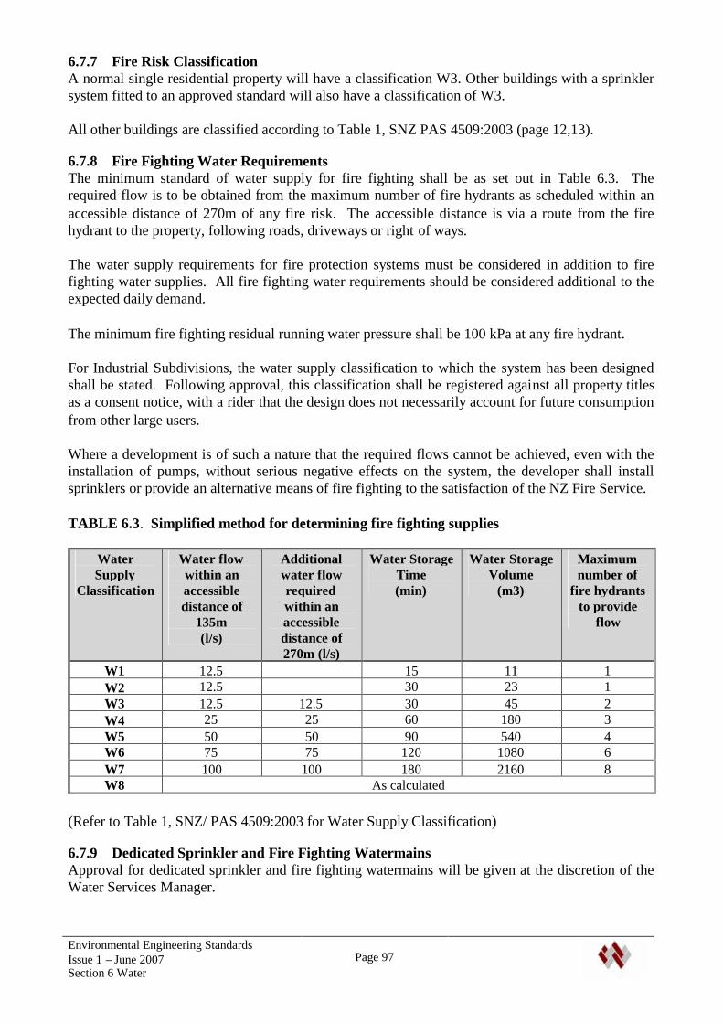
Environmental Engineering StandardsIssue 1 – June 2007Section 6 Water
Page 97
6.7.7 Fire Risk ClassificationA normal single residential property will have a classification W3. Other buildings with a sprinklersystem fitted to an approved standard will also have a classification of W3.
All other buildings are classified according to Table 1, SNZ PAS 4509:2003 (page 12,13).
6.7.8 Fire Fighting Water RequirementsThe minimum standard of water supply for fire fighting shall be as set out in Table 6.3. Therequired flow is to be obtained from the maximum number of fire hydrants as scheduled within anaccessible distance of 270m of any fire risk. The accessible distance is via a route from the firehydrant to the property, following roads, driveways or right of ways.
The water supply requirements for fire protection systems must be considered in addition to firefighting water supplies. All fire fighting water requirements should be considered additional to theexpected daily demand.
The minimum fire fighting residual running water pressure shall be 100 kPa at any fire hydrant.
For Industrial Subdivisions, the water supply classification to which the system has been designedshall be stated. Following approval, this classification shall be registered against all property titlesas a consent notice, with a rider that the design does not necessarily account for future consumptionfrom other large users.
Where a development is of such a nature that the required flows cannot be achieved, even with theinstallation of pumps, without serious negative effects on the system, the developer shall installsprinklers or provide an alternative means of fire fighting to the satisfaction of the NZ Fire Service.
TABLE 6.3. Simplified method for determining fire fighting supplies
WaterSupply
Classification
Water flowwithin anaccessibledistance of
135m(l/s)
Additionalwater flowrequiredwithin anaccessibledistance of270m (l/s)
Water StorageTime(min)
Water StorageVolume
(m3)
Maximumnumber of
fire hydrantsto provide
flow
W1 12.5 15 11 1W2 12.5 30 23 1W3 12.5 12.5 30 45 2W4 25 25 60 180 3W5 50 50 90 540 4W6 75 75 120 1080 6W7 100 100 180 2160 8W8 As calculated
(Refer to Table 1, SNZ/ PAS 4509:2003 for Water Supply Classification)
6.7.9 Dedicated Sprinkler and Fire Fighting WatermainsApproval for dedicated sprinkler and fire fighting watermains will be given at the discretion of theWater Services Manager.
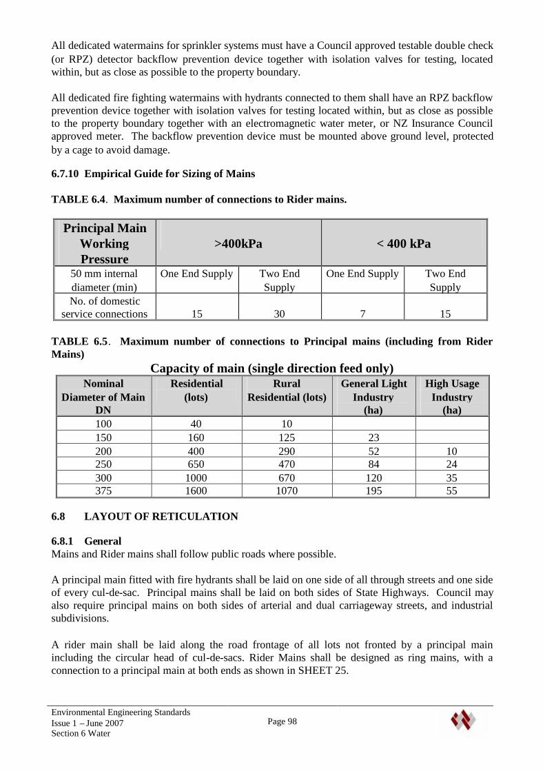
Environmental Engineering StandardsIssue 1 – June 2007Section 6 Water
Page 98
All dedicated watermains for sprinkler systems must have a Council approved testable double check(or RPZ) detector backflow prevention device together with isolation valves for testing, locatedwithin, but as close as possible to the property boundary.
All dedicated fire fighting watermains with hydrants connected to them shall have an RPZ backflowprevention device together with isolation valves for testing located within, but as close as possibleto the property boundary together with an electromagnetic water meter, or NZ Insurance Councilapproved meter. The backflow prevention device must be mounted above ground level, protectedby a cage to avoid damage.
6.7.10 Empirical Guide for Sizing of Mains
TABLE 6.4. Maximum number of connections to Rider mains.
Principal MainWorkingPressure
>400kPa < 400 kPa
50 mm internaldiameter (min)
One End Supply Two EndSupply
One End Supply Two EndSupply
No. of domesticservice connections 15 30 7 15
TABLE 6.5. Maximum number of connections to Principal mains (including from RiderMains)
Capacity of main (single direction feed only)Nominal
Diameter of MainDN
Residential(lots)
RuralResidential (lots)
General LightIndustry
(ha)
High UsageIndustry
(ha)100 40 10150 160 125 23200 400 290 52 10250 650 470 84 24300 1000 670 120 35375 1600 1070 195 55
6.8 LAYOUT OF RETICULATION
6.8.1 GeneralMains and Rider mains shall follow public roads where possible.
A principal main fitted with fire hydrants shall be laid on one side of all through streets and one sideof every cul-de-sac. Principal mains shall be laid on both sides of State Highways. Council mayalso require principal mains on both sides of arterial and dual carriageway streets, and industrialsubdivisions.
A rider main shall be laid along the road frontage of all lots not fronted by a principal mainincluding the circular head of cul-de-sacs. Rider Mains shall be designed as ring mains, with aconnection to a principal main at both ends as shown in SHEET 25.
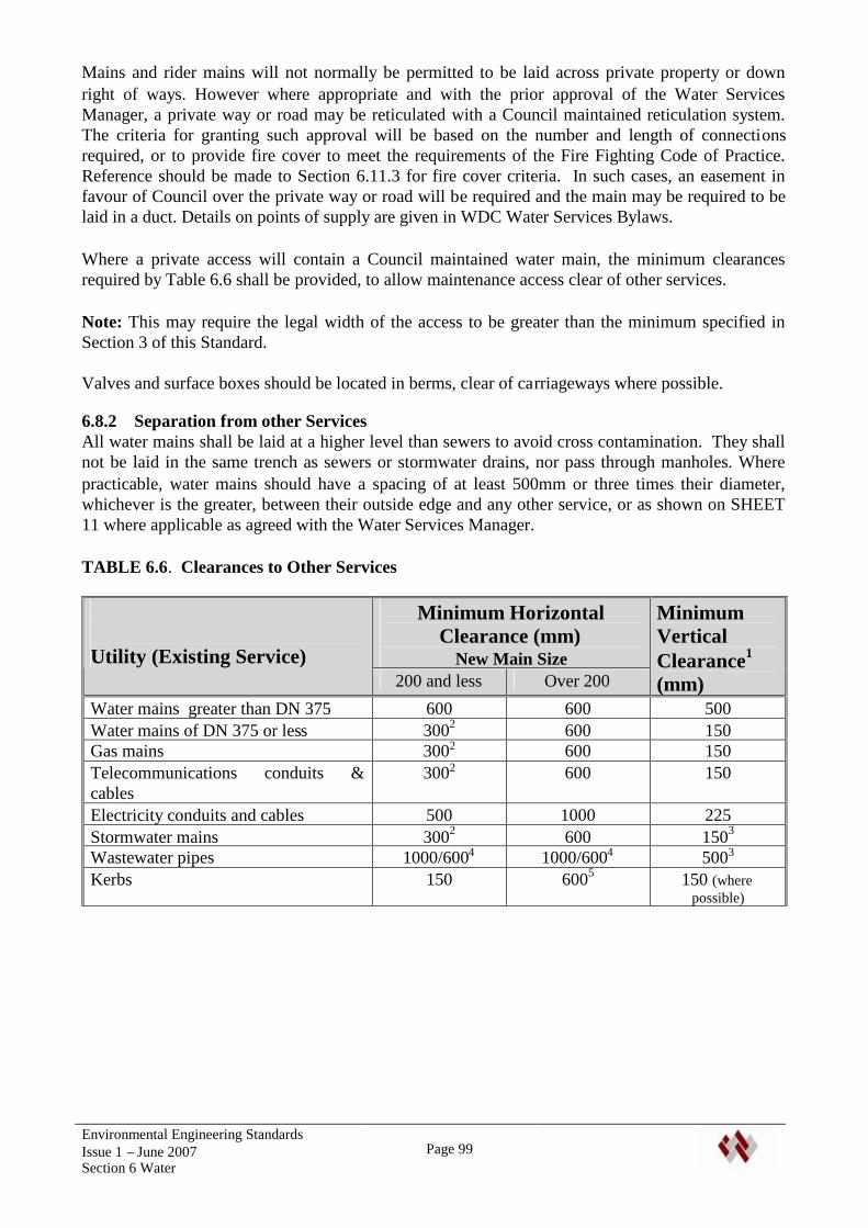
Environmental Engineering StandardsIssue 1 – June 2007Section 6 Water
Page 99
Mains and rider mains will not normally be permitted to be laid across private property or downright of ways. However where appropriate and with the prior approval of the Water ServicesManager, a private way or road may be reticulated with a Council maintained reticulation system.The criteria for granting such approval will be based on the number and length of connectionsrequired, or to provide fire cover to meet the requirements of the Fire Fighting Code of Practice.Reference should be made to Section 6.11.3 for fire cover criteria. In such cases, an easement infavour of Council over the private way or road will be required and the main may be required to belaid in a duct. Details on points of supply are given in WDC Water Services Bylaws.
Where a private access will contain a Council maintained water main, the minimum clearancesrequired by Table 6.6 shall be provided, to allow maintenance access clear of other services.
Note: This may require the legal width of the access to be greater than the minimum specified inSection 3 of this Standard.
Valves and surface boxes should be located in berms, clear of carriageways where possible.
6.8.2 Separation from other ServicesAll water mains shall be laid at a higher level than sewers to avoid cross contamination. They shallnot be laid in the same trench as sewers or stormwater drains, nor pass through manholes. Wherepracticable, water mains should have a spacing of at least 500mm or three times their diameter,whichever is the greater, between their outside edge and any other service, or as shown on SHEET11 where applicable as agreed with the Water Services Manager.
TABLE 6.6. Clearances to Other Services
Minimum HorizontalClearance (mm)
New Main SizeUtility (Existing Service)200 and less Over 200
MinimumVerticalClearance1
(mm)Water mains greater than DN 375 600 600 500Water mains of DN 375 or less 3002 600 150Gas mains 3002 600 150Telecommunications conduits &cables
3002 600 150
Electricity conduits and cables 500 1000 225Stormwater mains 3002 600 1503
Wastewater pipes 1000/6004 1000/6004 5003
Kerbs 150 6005 150 (wherepossible)
Environmental Engineering StandardsIssue 1 – June 2007Section 6 Water
Page 100
Notes1) Vertical clearance apply when water mains cross another utility service, except in the case of
wastewater when a vertical clearance shall always be maintained, even when the main andwastewater pipe are parallel. The main should always be located above the wastewater pipe tominimize the possibility of backflow contamination in the event of a main break.
2) Clearance can be reduced further to 150mm for distances of up to 2m when passinginstallations such as pole, pits and small structures, providing the structure is not destabilizedin the process.
3) Water mains should always cross over wastewater and stormwater drains.4) When a wastewater pipe is at the minimum vertical clearance below the water main (500mm),
maintain a minimum horizontal clearance of 1000mm. This minimum horizontal clearancecan be progressively reduced to 600mm as the vertical clearance is increased to 750mm.
5) Clearance from the kerb and channel shall be measured from the nearest edge of the concrete.For water mains DN 375 and less clearances can be progressively reduced until the minimumof 150mm is reached for mains of DN 200 and less.
6) Where a main crosses other services, it shall cross at an angle as near as possible to 90o.7) Clearance shall be measured from the outside of each pipe or duct.
6.8.3 Water Mains Near Trees and Existing ReticulationReference shall be made to Section 7.5 of this Standard for requirements regarding the location oftrees close to water reticulation. Where any pipes or cables are laid alongside existing waterreticulation then a gap of at least 1 metre is to be maintained where practicable so as not to disturbthe existing trench.
6.8.4 Pipe CoverAll reticulation located in areas not subject to traffic loading shall have a minimum of 600 mm ofcover between the top of the pipe and finished ground level. Under carriageways this distance shallbe increased to 900 mm. In all other circumstances not meeting the minimum requirements statedthen special protection of the pipe is to be provided, subject to Council approval. Details of pipeprotection are shown on SHEET 19. The Council may specify a greater depth if required. Whereexcavations for entrances to developments encounter existing water supply lines, those lines shall berelocated to comply with the depth requirements of this document.
The sections of pipe adjacent to a carriageway crossing shall be gradually deepened either side ofthe carriageway, to allow the required cover to be achieved under the carriageway without provisionof vertical bends. Air valves may be required on the resulting crests in the pipe.
All pipes less than 500mm under carriageways shall be laid in a larger protective duct. Serviceconnections shall not be less than 600 mm under footpaths and berms terminating at a metermanifold as per SHEET 26.
6.8.5 Work on Existing Water MainsWhere work is required on or over existing water mains, the developer may be required to lower,move or protect the main to ensure cover and separation distances are met. Only LicensedContractors will be permitted to work on existing live water mains. The developer shall pay the fullcost of this work.
Environmental Engineering StandardsIssue 1 – June 2007Section 6 Water
Page 101
6.8.6 Thrust and Anchor BlocksOn all mains exceeding 50mm diameter where no end restraint is available, concrete anchor blocksshall be provided at all valves, bends, tees, reducers and dead ends. Generally anchor/thrust blocksare not required on PE mains, except where a connection is made to an unrestrained pipe or fitting.
The size of the bearing surfaces shall be specifically designed. SHEETS 27 & 28 give guidelinesfor shape and size for a soil with a bearing pressure of 100 kPa and a design pressure of 1500 KPa.The concrete shall be ordinary grade concrete supplied from a graded plant, and have a minimumcompressive strength of 17.5Mpa at 28 days, unless otherwise approved by the Water ServicesManager. All anchor blocks must be poured using adequate formwork, with the bearing surfacepoured against an undisturbed soil surface. A protective wrapping shall be provided between thepipe and concrete. Reference should be made to drawings WS-003, 004 & 005 in NZS 4404:2004for typical thrust block locations when used with pipes without end restraint.
If reticulation is being extended from the end of an existing pipe with a blank cap and thrust block,the thrust block shall be removed and the new pipe continued in the same alignment as the originalpipe.
6.9 VALVES AND FITTINGS
6.9.1 GeneralAll valves and fittings shall be in accordance with the Whangarei District Council’s approvedmaterials list, the main points of which are summarised below.
Pipe fittings above ground, or in non-aggressive ground conditions, shall be ductile iron to AS 1831,powder coated with Rilsan 11 or approved equivalent to AS/NZS 4158. Where applicable theyshall comply with AS/NZS 2280.
Flanges shall be to AS 4087 PN16 . Fittings laid adjacent to other fittings shall have flanged joints.Where fittings are located in on-line positions, flexible (gibault) joints may be permitted subject toapproval of the Council (Note that gibault joints may not be used on PE pipe)..
All bolts and nuts shall have washers and be 316 stainless (see specifications for mains), plusprotective wrapping. This shall be “Denso” primer paste covered with “Denso” tape wrap ,followed by “Denso” MP/HD tape or “Greensleeve” over wrap, or approved alternatives complyingwith the same standards.
6.9.2 Sluice Valves and Peet Valves
6.9.2.1 TypeSluice Valves used on principal mains shall be ductile iron Resilient Seated valves to AS 2638.2 –1999 and fully nylon coated to AS/NZS 4158. They shall be bi-directional, anti-clockwise closing,have raised flange faces to AS 4087 and shall be provided with cast iron spindle caps. The depth tothe top of the spindle shall be where practicable between 75mm and 250mm and the spindle shall betruly vertical. Where depth to the spindle exceeds 500mm a spindle extension shall be used to bringthe top of the spindle between 75mm and 250mm of the surface.
Peet Valves used on rider mains shall be ductile iron Resilient Seated valves to AS 2638.2 – 1999and fully nylon coated to AS/NZS 4158. They shall be clockwise closing with a ductile ironhandwheel. They shall have a threaded end connections to which a 63mm PE compression couplingcan be screwed.
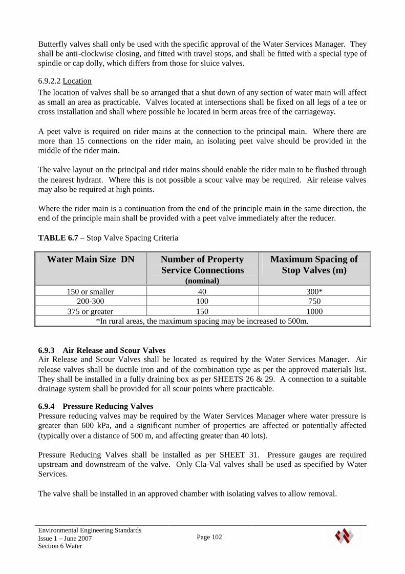
Environmental Engineering StandardsIssue 1 – June 2007Section 6 Water
Page 102
Butterfly valves shall only be used with the specific approval of the Water Services Manager. Theyshall be anti-clockwise closing, and fitted with travel stops, and shall be fitted with a special type ofspindle or cap dolly, which differs from those for sluice valves.
6.9.2.2 LocationThe location of valves shall be so arranged that a shut down of any section of water main will affectas small an area as practicable. Valves located at intersections shall be fixed on all legs of a tee orcross installation and shall where possible be located in berm areas free of the carriageway.
A peet valve is required on rider mains at the connection to the principal main. Where there aremore than 15 connections on the rider main, an isolating peet valve should be provided in themiddle of the rider main.
The valve layout on the principal and rider mains should enable the rider main to be flushed throughthe nearest hydrant. Where this is not possible a scour valve may be required. Air release valvesmay also be required at high points.
Where the rider main is a continuation from the end of the principle main in the same direction, theend of the principle main shall be provided with a peet valve immediately after the reducer.
TABLE 6.7 – Stop Valve Spacing Criteria
Water Main Size DN Number of PropertyService Connections
(nominal)
Maximum Spacing ofStop Valves (m)
150 or smaller 40 300*200-300 100 750
375 or greater 150 1000*In rural areas, the maximum spacing may be increased to 500m.
6.9.3 Air Release and Scour ValvesAir Release and Scour Valves shall be located as required by the Water Services Manager. Airrelease valves shall be ductile iron and of the combination type as per the approved materials list.They shall be installed in a fully draining box as per SHEETS 26 & 29. A connection to a suitabledrainage system shall be provided for all scour points where practicable.
6.9.4 Pressure Reducing ValvesPressure reducing valves may be required by the Water Services Manager where water pressure isgreater than 600 kPa, and a significant number of properties are affected or potentially affected(typically over a distance of 500 m, and affecting greater than 40 lots).
Pressure Reducing Valves shall be installed as per SHEET 31. Pressure gauges are requiredupstream and downstream of the valve. Only Cla-Val valves shall be used as specified by WaterServices.
The valve shall be installed in an approved chamber with isolating valves to allow removal.
Environmental Engineering StandardsIssue 1 – June 2007Section 6 Water
Page 103
6.10 VALVE MARKINGThe position of all valves on water mains shall be indicated by a white plastic indicator post to theCouncil's approval bearing the inscribed letters ‘SV’, ‘AV’, ‘BV’ or ‘PV’ in black to indicate eithersluice valves, air valves, butterfly valves or peet valves, respectively. The name of the valve shallalso be stencilled on the top of the marker post in adhesive black lettering along with the size of themain on which it is situated and the distance of the post from the main. The name can be obtainedfrom the Water Services Manager.
There shall also be a rectangle painted on the kerb in a direct line between the valve and the markerpost. This rectangle shall be white unless the valve is to be normally closed in which case it shall bered. In all cases the colour of the marker post and valve box lid shall match the rectangle.
The location of valves shall be marked in carriageways using Thermoplastic lid coating.
6.11 HYDRANTS
6.11.1 GeneralAll mains of 100mm diameter or greater shall be provided with hydrants.
6.11.2 TypeHydrants shall be ductile iron, clockwise closing, screw down type generally in accordance withB.S. 750:1984, and shall wherever practicable be tall pattern. Hydrants and hydrant risers are to befully coated inside and out with blue nylon to AS/NZS 4158. The hydrant stopper shall be resilientseated and encapsulated in Nitrile or EPDM rubber. Spindles shall be non rising stainless steel orDR brass, stem seals shall be nitrile rubber ’ O’ rings (gland packing is not acceptable). HydrantTees shall be ductile iron and coated in Rilsan 11 or approved alternative complying with AS/NZS4158:1997. The sealing cup washer shall be of nitrite rubber and the gland seal shall be either ofbraided PTFE yarn or a minimum of two captive ‘O’ sealing rings.
Hydrants shall not be self-draining.
6.11.3 PositionHydrants shall be fixed opposite the common boundaries of lots and spaced at intervals notexceeding 135m within residential areas and 90m within commercial and industrial areas. Theterminal hydrant shall be within 135m of the furthermost portion of any building site along a routethat is fully accessible*. In a cul-de sacs or other terminal streets the last hydrant shall be as perSHEET 25 and not be more than 65m from the end of the street. Where a private way is more than65m long a hydrant shall be provided at the street end of the private way or on the other side of thestreet immediately opposite the entrance. The Council may require a 100 mm diameter principalmain with hydrant to be constructed within a private way or private road to ensure fire coverage. Inthis instance an adequate turning and parking area for fire appliances in the vicinity of the hydrantshall be provided and the access designed to take heavy vehicles.
Where an isolated risk is identified such as a school or large industrial complex, a private fire linemay be constructed onto that lot. No reticulation shall be taken off this line. Meter and backflowrequirements shall be as specified in Section 6.7.9.
Hydrants must be readily accessible* for fire appliances and should generally be positioned nearstreet and private way intersections and at least 6m from any building. Hydrant risers shall be usedwhere necessary to ensure that the top of the spindle is not less than 75 mm nor greater than 250mm below finished surface level. Hydrants are required at all dead ends, high points for the purpose
Environmental Engineering StandardsIssue 1 – June 2007Section 6 Water
Page 104
of air release, and low points to enable mains flushing if a normal washout cannot be fitted. Referalso to Air Release and Scour Valves.
* The definition of accessible is a route from the fire hydrant to the building or building sitefollowing roads, driveways or right of ways.
6.11.4 MarkingThe location marking of fire hydrants shall be to NZS4501:1972. Markings in carriageways andfootpaths shall use yellow Thermoplastic Hydrant Markers, and blue ‘Cats-Eye’ markers shall belocated on the hydrant side of the road centreline. Yellow plastic marker posts to the Council'sapproval shall be fixed 225 mm from the street boundary at the closest point to and facing thehydrant, with the top of the post 600 mm above finished ground level. A concrete mowing strip150 mm wide shall surround the post when it is set in the grassed berm. The hydrant name (topnumber), correct main size in millimetres (middle number) and the distance between marker andhydrant in metres (bottom number) shall be attached to the post using black adhesive lettering nearthe top of the post. The hydrant name shall be allocated by the Water Services Manager.
6.12 SURFACE BOXESAll valves and hydrants shall be accessible via surface boxes, details of these are shown onSHEETS 27 and 29. All boxes shall be cast iron or ductile iron and be directly above the valve orhydrant. The longer side of the boxes shall run parallel to the water main. The box shall besupported on concrete risers sized to provided unobstructed access to the valve or hydrant. In thecase of hydrants, this shall include easy access for standpipes and installation of data loggingequipment. Care shall be taken to ensure loading from traffic is not transmitted via the box andsurrounds to the pipe or fittings. Where a valve is particularly deep, a length of 150mm PVC pipeshall be used to direct the valve key to the spindle. This does not remove the requirement forconcrete surrounds. All surface boxes shall be heavy duty. Hydrant boxes in road carriagewaysshall be manufactured to BS 750. Hydrant boxes in arterial roads and State Highways shall beMotorway Grade.
All surface boxes shall be correctly coloured using thermoplastic in carriageways and footpaths, andpaint in berms.
6.13 BULK WATER METERSThe Water Services Manager may require the provision of a bulk water meter at the connectionpoint of the reticulation. This will normally only be required where there are greater than 20industrial connections, 40 commercial or 150 residential connections.
The meter shall be a full bore ‘Aquamag’ meter with data logger.
6.14 SERVICE CONNECTIONS
6.14.1 GeneralA service connection shall be provided for each single lot or residential unit with individual streetfrontage. The connection shall be perpendicular to the main or ridermain and terminate 100 mmfrom the boundary with a Water Services approved manifold (Acuflo) including diaphragmisolation valve and dual check valve and blue meter box with base. The manifold shall be blankedoff with a brass plug and 5mm hole drilled in the cap of the manifold. Refer to SHEET ***.
For private ways and private roads, a single connection, with size determined as for a rider main isto be provided within the legal road not exceeding 500 mm from the road boundary. A peet valve isto be installed at the junction to the main. At the road boundary a multiple meter box shall be
Environmental Engineering StandardsIssue 1 – June 2007Section 6 Water
Page 105
provided and sized according to the table on SHEET 26. Separate connections shall then beprovided to each lot from the box. The lot number of each connection shall be clearly marked withinthe box. Where lots are situated up a private way or similar, connections shall split either sidewhere practicable to avoid passing under the roadway and be extended to beyond the shared access.
Where a Council maintained water main is provided along a private access or road, connections maybe provided from this main to each property.
Backflow prevention shall be provided at all metered connections in accordance with clause 6.14.4
6.14.2 MetersMeters are not to be installed during subdivision or development but are to be applied for separatelyfor each lot using a Public Utility Service Connection Form.
The only exceptions to this are for water supplies for public assets that will be maintained byCouncil in future (e.g. a sewer pumping station or irrigation system for a reserve). In these instancesan application shall be made to Water Services for the connection, including written confirmationfrom the relevant Council Division that will be paying for the water. The correct utility as-builtform shall still be submitted to the Water Services Division as per the specification for serviceconnections. However, the meters and backflow preventers shall be installed at the time ofconnection. Note: the developer shall apply for these connections, and pay all costs, includingDevelopment Contributions for the connections.
For connection sizes up to 20mm, meters shall be Class C manifold type meters. For connectionslarger than 20mm diameter, the advice of the Water Services Manager shall be sought as to the typeof meter and backflow preventer.
6.14.3 Connection to water mainService connection to a principal main or rider main shall be with an electrofusion tapping saddle.Tapping saddles on PE80/PE100 pipes shall be with ball valves or self-tapping ferrules at the pointof connection, installed strictly in accordance with the manufacturer’s instructions. Connectionbetween the tapping saddle and the service connection shall be made using an approvedcompression fitting.
All materials and fittings must be approved by the Water Services Manager and installed strictly inaccordance with the manufacturers recommendations.
The tapping saddle for each service connection shall be sited at the central point of the frontboundary or house site, and clear of any driveways or access ways. The position shall be marked onthe kerb with a 125 mm square of blue paint; in addition a notch 12mm wide and 12mm deep shallbe cut in the top of the kerb before painting. Service connections laid across roads or drivewaysshall be laid in a larger duct. Service connections shall be PE80 PN12 pipe of 20mm internaldiameter unless otherwise approved by the Water Services Manager. All fittings used shall bemechanical and comply with WIS 4/2401 and are to be as per the Water Services ApprovedMaterials List.
6.14.4 Backflow PreventionAll connections shall be provided with a dual check valve Backflow Preventer, as a minimum.These shall be installed in the manifold. Where the Water Supply Protection Regulations 1961require a greater level of protection, they shall be installed appropriate to the level of contaminationrisk. For sewer pumping stations a reduced pressure zone backflow preventer shall be installed,
Environmental Engineering StandardsIssue 1 – June 2007Section 6 Water
Page 106
above ground, in a protective cage. All backflow preventers must be installed with isolating valvesand be fully testable. The general layout for the installation of a backflow preventer is shown onSHEET 26. More details of where backflow preventers are required can be found in the WhangareiDistrict Council Backflow Prevention and Cross Connection Control Policy and the WhangareiDistrict Council Water Supply Bylaw.
6.15 PUMP STATION AND RESERVOIRSA pump station may need to be provided where an increase in pressure is required. Where possiblethe pump station should be linked to an appropriate sized reservoir. Where no reservoir site isavailable a pressure sustaining system may be used. Pump Stations shall be designed in accordancewith SHEET 32, and other WDC Water Supply Pumping Station documents.
The design of these components must be approved by the Water Services Manager or authorisedrepresentative. Pumps shall be capable of maintaining the pressures and flows required, withreserve capacity. A standby pump must be provided.
Reservoirs shall be of concrete construction. They shall be sized to provide: A fire fighting supply as specified in the New Zealand Fire Service Fire Fighting Water
Supplies Code of Practice SNZ PAS 4509:2003, with a minimum of one hours supply. Sufficient storage for two days supply at maximum daily demand, plus additional future
demand as assessed by the Council.
A Council approved telemetry link will need to be provided for control of pumps and reservoirlevels. The reservoir and pump station site shall be vested in the Council. An access and watersupply easement will also be required where the supply line runs over private property.
6.16 CONTRACTOR QUALIFICATIONSReference should be made to Section 1.9 regarding Registered and Licensed Contractors.
Only Contractors, Registered with the Whangarei District Council shall install or work on waterassets that will become part of the public system. The scope of work that a Registered Contractor ispermitted to perform shall be in terms of their Approval.
Registered Contractors shall comply with the following: Be familiar with this Standard and relevant related documents, and be suitably experienced and
qualified to work with the relevant pipe materials. Have staff that have successfully completed an approved welding course recognised by the
NZWWA to undertake jointing procedures on polyethylene pipes (PE80/PE100) of greater than63mm OD.
Have staff that have completed the relevant unit standards in Water Reticulation as required byWDC Specification for Registered and Licensed Contractors for Water Supply
Be a Whangarei District Council Certified Health and Safety approved Contractor They must strictly follow the provisions of the Whangarei District Council’s Hygiene Code. Hold insurance as required by Section 1.13.14.
Connections to live water pipelines shall only be undertaken by Licensed Contractors to the WDCWater Services Division, who have been approved to work on live reticulation.
For work on live water mains, Licensed Contractors must have passed the National Certificate inWater Reticulation (or relevant sections) and be in possession of their Blue Card at all times.
Environmental Engineering StandardsIssue 1 – June 2007Section 6 Water
Page 107
Contractors who produce workmanship of a substandard quality or fail to comply with thesestandards will be removed form the Registered Contractor list.
6.17 PIPELINE CONSTRUCTION
6.17.1 JointingPipe laying and jointing shall be as recommended by the manufacturer, and as required by theapplicable Standard for the type and class of pipe.
Joints in PE pipes of greater than 50mm ID shall be welded joints unless the Water ServicesManager approves the use of mechanical fittings.
100 mm ID pipes (125mm OD), may be supplied in coils, and joined using electrofusion couplers.
Where pipe is supplied in 6 m or 12 m lengths, and the pipeline length is greater than 50 m, jointsshall be butt welded.
Only pipes of the same Melt Flow Index shall be welded together. Pipes from different suppliers ordifferent batches shall not be welded.
Welding (butt or electrofusion) of PE pipes shall be undertaken by a suitably qualified contractorusing calibrated and data logged welding machines. Only persons who have successfully completeda NZWWA approved welding course and are registered to weld polyethylene pipe shall be allowedto do so. Prior to commencing work, the following shall be provided:
Copy of current calibration certificate, not more than 12 months old. Registration number of welder, and current certification (not older than 24 months)
All welding of PE pipe must be data logged. Welding must take place in a covered environment toavoid contamination of weld faces and prepared pipe.
For all electrofusion welds, a mechanical scraper with winding mechanism shall be used to ensureeven finishing. Hand scraping of pipe ends is not acceptable.
Electrofusion welds shall be undertaken using clamps where practicable and the equipment correctlycalibrated.
For welded pipelines, one or more welded joints shall be removed for tensile testing. The testsample(s) shall be sent to an approved laboratory for testing at the contractors expense. If a testweld fails, two additional welds shall be tested. If one of the additional welds also fails the pipemust be removed and condemned and a new line laid.
The jointing of flanged fittings to PE pipe shall be with stub flanges and backing rings. Backingrings shall be mild steel and plastic coated with Rilsan 11 or approved alternative, and be to theAS/NZS 4158 standard. The thickness of the backing rings shall be as shown in Table 6.8.
Environmental Engineering StandardsIssue 1 – June 2007Section 6 Water
Page 108
TABLE 6.8. Thickness of Backing rings on PE water pipe joints.
Pipe OutsideDiameter (mm)
Backing RingThickness (mm)
125 16180 16250 16315 20
For pipes over 180mm OD, slim flanges with reinforced faces shall be used. Gaskets must be usedfor all flanged connections.
During transportation and on site storage temporary capping of all pipes as per the WhangareiDistrict Council’s Hygiene Code is required. The pipes shall be inspected externally immediatelyprior to laying to check for damage in accordance with the manufacturers specifications. Aninternal inspection should also be carried out and adequate protection against the ingress of debrisshall be made as laying proceeds. Temporary caps shall be placed over all open ends duringconstruction.
6.17.2 Water Main InstallationPipe bedding and backfill requirements are detailed on SHEET 18.
All pipes shall be laid so that the identification code is uppermost where practical, and shall beevenly supported along their length. All mains and rider mains installed by trenching shall bethoroughly bedded and protected by a well hand-compacted granular material. The particle sizerange of this material shall be as shown on SHEET 18 and shall meet the requirements of thecompaction test given in Appendix B of NZS 7643 regardless of pipe material. The beddingmaterial shall be placed in layers of less than 100mm and shall surround the pipe by at least 100 mmin all directions.
Reinstatement of trenches in existing carriageways shall comply with the requirements of the WDCWorking Within Road Reserves Policy and Specification
6.17.3 Detection TapeA metallic detection tape and tracer cable shall be laid directly above all new non-metallic watermains including rider mains.
Detection tape shall have “water” written on it in blue, be located at a depth of between 200 and250mm below the finished surface level and contain sufficient metal to be detectable from thesurface by a standard metal detector.
Tracer cable shall also be attached to all principal mains and rider mains. This wire shall take theform of a continuous 2.5mm2 multi strand (polythene sleeved) cable, strapped to the pipe wall bymeans of a minimum of two complete wraps of heavy duty adhesive tape, at a maximum of 3.0mintervals. The tracer cable shall be connected to all surface boxes, and electrically tested forcontinuity by a Registered Electrician following installation and backfilling. Records of theelectrical continuity test shall be provided by the Contractor.
Environmental Engineering StandardsIssue 1 – June 2007Section 6 Water
Page 109
6.17.4 Special Measures in Aggressive Ground ConditionsWhere aggressive soil conditions are likely to be encountered, only approved Water Servicesmaterials are to be used. For metal components, the approved materials are stainless steelcomplying with NZS 3604 Grade 316, Ductile Iron coated to NZS 4158 or aluminium-bronze.Additionally, all metal shall have a molybond coating corrosion protected with “Denso” primerpaste covered with “Denso” tape wrap , followed by “Denso” MP/HD tape or “Greensleeve” overwrap, or approved alternative complying with the same standards.
The Water Services Manager shall be the sole judge as to what constitutes “aggressive” groundconditions.
6.18 DISINFECTION AND TESTING
6.18.1 Pressure TestingOn completion of the pipe laying and jointing, sufficient backfill materials shall be placed over thepipes to prevent movement during pressure testing, leaving joints, fittings and anchor blocks visible.
No connections of a permanent nature between existing mains and the new work will be allowed atthis stage. PE80 rider mains shall not to be connected to the mains before testing, but shall be testedseparately. Service connections shall be included within the test.
To complete the preliminary test the new reticulation system shall be swabbed and any aireliminated using a temporary supply. All valves on the new main shall be fully opened and allhydrants, stop taps and valves on the consumer end of the service pipes shall be shut. Water fortests may be obtained from the existing system provided prior Water Services Division approval isobtained and a metered standpipe with a check valve is used. Standpipes are available from theWater Services Division.
A visual inspection of the line including joints and fittings shall be made and any apparent flaws andleaks shall be remedied. The pipe shall be left full overnight before pressure testing.
Pressure tests shall be carried out using an approved pressure pump at a steady rate without shockloading. Pressure gauges used shall be accurate and read to a minimum of 10kPa intervals. NB:Gauges shall be calibrated on an annual basis, with test certificates available for all equipment onrequest.
The Contractor shall give the Water Services Manager at least 24 hours notice before carrying outtesting. The test shall be carried out in the presence of a Council representative and a data loggershall be used to verify the results.
The test pressure shall be 1.25 x the rated pressure of the pipe. Test sections shall not exceed 500min length. The specified test pressure is the pressure to be applied at the lowest point in the section.If the pressure gauge is not located at the lowest point a correction shall be made for the differencein levels. Pressure testing against valves will not be permitted.
For PE80 or PE 100 pipe the type of test will depend on the length and diameter of pipe to be tested.The Contractor shall confirm with the Water Services Manager which test is required in accordancewith the manufacturer's requirements and the “Whangarei District Council Specification for theInstallation of Water Mains”. The Contractor shall supply a graph or data logger printout of thepressure test and show calculations n1 and n2 where applicable.
Environmental Engineering StandardsIssue 1 – June 2007Section 6 Water
Page 110
The applicants, its representatives and contractors are reminded of their obligations under theResource Management Act in terms of the discharge of testing water into natural water courses. Itwill only be acceptable to discharge the water into a Council-managed stormwater system if it is of aquality that would comply with the requirements of the relevant Catchment Drainage Plan or therules in the Northland Regional Council Water and Soil Plan for Northland). Testing water shallnot be discharged into a Council-managed sewerage system.
6.18.2 DisinfectionAfter backfilling and before being put into service, all pipes, valves, house connections and otherfittings shall be disinfected. All disinfection testing will be at the developer’s cost.
Disinfection Testing shall be carried out by persons who have successfully completed NZQA UnitStandard 19209 - Water Reticulation (Demonstrate knowledge of water reticulation system cleaningand disinfection).
The main shall firstly be swabbed with a suitable swab if not already done prior to pressure testing.The main shall then be drained and slowly filled with potable water to which sufficient free chlorineis added to produce a concentration of 50 parts per million in the main. It is recommended this bedone via a water tanker of known volume.
The point of water application shall be at the beginning of the section of main to be sterilised.
The main shall be left full of the chlorinated water for 24 hours, during which time all valves,hydrants and other fittings on the section shall be operated.
The residual chloride concentration must not be less than 20 ppm after 24 hours.
The main shall then be flushed out until the chlorine concentration of the issuing water is between 2and 0.2 parts per million.
If the chlorination is found to be unsatisfactory, the Contractor shall repeat the procedure until thewater is of acceptable quality.
The testing of the chlorine concentration is to be carried out on site by the Whangarei DistrictCouncil Wastewater laboratory or other approved laboratory. It is the Contractors responsibility toorganise the laboratory representative to be on site. At least 24 hours notice is required for theinitial chlorine application. The representative shall return 24 hours later for the second residualchlorine test and will stay on site while the line is flushed until the chlorine concentration isbetween 2 and 0.2ppm.
The laboratory will then issue the Council a report in writing confirming the tests.
Chlorine may be added to the pipe in one of the following ways:
a) Chloride of lime solutionb) Calcium hypochlorite solutionc) Sodium hypochlorite solutiond) HTH dry chlorine granules dissolved in water
before put into the main
NB: The chlorine solution must not be discharged into the stormwater system.
Environmental Engineering StandardsIssue 1 – June 2007Section 6 Water
Page 111
Following approval by the Council of the tests and provided all other aspects of the pipeworkare satisfactory Form WB will be completed by a Water Services representative.
Upon completion of Form WB the applicant shall keep the new reticulation continuously chargedwith water under pressure and obtain Council approval to connect to the existing reticulation. Thisis requested by notifying Water Services in writing and providing a copy of form WB, the testresults and a sketch of the connection detail. The Licensed Contractor who will undertake the workmust be identified and the Council file and property identification numbers shown. The connectionshall only be made by the (Council approved) contractor shown in the application. Upon connectionthe new reticulation is to be flushed to the satisfaction of the Council, and left operational.
If the main to be connected is deemed by the Water Services Manager to be critical, then only theReticulation Maintenance Contractor may undertake the connection.
All costs associated with connection to the existing system shall be met by the developer.
6.18.3 Hydrant Flow TestFollowing completion of the pipe test and connection to the main, the developer may be required toprovide certification from the Fire Service or other approved independent certifier, of the staticpressure, the maximum flow and the residual pressure at maximum flow for each hydrant.
6.19 COMPLETION
6.19.1 As-Built Drawings and Schedule of Asset InformationA set of drawings and a schedule of asset information shall be submitted as per Section 1.7 of thisStandard, and the checklist attached to Form WC. These shall clearly and accurately show the as-built locations and details of all water infrastructure provided as part of the work, including anymodifications made to the existing system.
Weld data logging information for all welds shall be submitted with As-Built drawings.
Additional information required for all hydrants, valves and meter box locations is as follows:
(i) Position - from LH, RH and front boundary of adjacent lot.(ii) Location - xyz co-ordinates.(iii) Item - hydrant, sluice valve, peet valve, pressure reducing valve.(iv) Make, model - depth to spindle/handle.(v) Date installed.(vi) For Hydrants - static pressure
- residual pressure- maximum flow rate
(vii) For valves - Number of turns to fully open.
The As Built drawings may be checked on site for accuracy on completion of the subdivisionor development. A certificate of completion for the works will not be issued until acceptable As-Built drawings have been produced and the requirements of Form WC met.

Environmental Engineering StandardsIssue 1 – June 2007Section 6 Water
Page 112
6.19.2 Operation and Maintenance ManualsFull details of all mechanical plant, including pump stations and treatment facilities shall beprovided, including complete O & M Manuals in PDF format, plus 3 hard copies, The O&MManuals shall include: As-built drawings, Equipment List, with make, model and serial numbers, Equipment supplier details, Pump curves, with design flow/head identified, Electrical layout, Control logic, Maintenance schedules.
6.20 DEFECTS LIABILITYA Performance Bond will be required for the works in terms of Section 1.13 of this Standard.
6.21 DRAWINGS
The following drawings in APPENDIX A apply to this section:
SHEET 1 STANDARD DRAWING SYMBOLSSHEET 11 RECOMMENDED SERVICE LOCATIONSSHEET 18 PIPE BEDDING AND BACKFILLSHEET 19 PIPE PROTECTION AND BULKHEAD DETAILSSHEET 28 RPZ WATER CONNECTIONSHEET 29 WATER PIPELINE DETAILSSHEET 30 MULTIPLE WATER CONNECTIONS & BACKFLOW PREVENTERSSHEET 31 SINGLE METER BOX CONNECTIONSHEET 32 ANCHOR BLOCK AND VALVE INSTALLATION DETAILSSHEET 33 ANCHOR BLOCK DIMENSIONSSHEET 34 AIR VALVE DETAILSSHEET 35 VALVE AND HYDRANT MARKERSSHEET 36 MAGFLOW AND PRESSURE REDUCING VALVE INSTALLATIONSHEET 37 WATER SUPPLY PUMP STATION DETAILS

Environmental Engineering StandardsIssue 1 – June 2007Section 7 Reserves
Page 113
7. RESERVES AND LANDSCAPE DESIGN AND PRACTICE
7.1 GENERAL REQUIREMENTSThis Section covers the requirements for the design of landscaping within parks, recreation andother reserves in the District. It should be read in conjunction with Parts 7 and 8 of NZS4404:2004.
7.2 REFERENCED DOCUMENTSThe following documents shall be read in conjunction with this section of these standards:
NZS 4404:2004 Land Development and Subdivision Engineering SNZ HB 8630:2004 Tracks and Outdoor Visitor Structure Standard. New Zealand Urban Design Protocol (Mfe, 2005)
7.3 SUBMISSION OF APPLICATION
7.3.1 Supporting Information and CalculationsThe application shall include the following: Plans showing existing mature trees and bush areas within the site, and proposed modifications
or enhancements to these areas, A landscape assessment of all areas to be designated as reserve, A development plan for reserves, Plans illustrating street planting, reserve planting, the alignment of footpaths, location of park
furniture, facilities structures, play equipment, lighting and landscape features such asmounding, stormwater ponds etc. proposed for the development,
Requirement for irrigation or other services. Fencing provisions
7.3.2 Design Drawings and SpecificationsDesign drawings shall comply with the requirements of Section 1.5 and 1.6.
7.3.3 Approval of DesignThe Parks Manager or his/her representative will review the drawings and return them to theapplicant’s representative, detailing any alterations that are required. If adjustments to the design arerequired a new set of amended drawings shall be submitted to the Council prior to approval beinggranted. Only drawings stamped and signed by the Parks Manager or authorised representative shallbe deemed approved drawings. Unless specifically stated otherwise, the approval of drawings doesnot supersede the requirements or obligations of these standards.
7.4 GENERAL
7.4.1 Concept stageLandscape design has application at all levels of the subdivision and development process. At theinitial concept stage it may be important to establish objectives for overall landscape designincluding open space connections, access to and location of watercourses, protection of remnantvegetation, and provision of reserves and streetscape to provide a framework of coherence andamenity. At a more detailed level landscape plantings may need to be located to minimise effectson vehicle sight lines.

Environmental Engineering StandardsIssue 1 – June 2007Section 7 Reserves
Page 114
7.4.2 Compatibility with engineering designLandscape design should be considered in the early stages of a development to ensure that anylandscape conditions and objectives are compatible with subsequent engineering design and works.Landscape design is intended to enhance the character and environment of a development, tostrengthen existing neighbourhood character and unify those areas into an integrated district.Landscape design may not be applicable to all developments and must be assessed in accordancewith the scale of the development, identification of positive effects that landscaping may provideand local conditions.
7.4.3 Long-term public benefitAny landscaping shall provide maximum long-term public benefit with minimum ongoingmaintenance costs, while giving due regard to the safe use of public assets.
7.4.4 ConservationAreas of natural significance, with inherent or potential conservation values, may be vested inCouncil as reserves. Alternatively, they may be vested with the Queen Elizabeth II Trust as OpenSpace Covenant, or as WDC Conservation Covenants.
Natural areas shall be weed and pest free, and a conservation plan prepared for the area, inaccordance with Resource Consent requirements.
7.4.5 Recreation reservesRecreation reserves to be vested in Whangarei District Council shall comply with Part 8 ofNZS4044: 2004.
Functional and aesthetic opportunitiesLandscaping provides a range of functional and aesthetic opportunities for environmentalenhancement:
Functional:
Defines space Provides shade, shelter and privacy Screens unsightly outlooks Ameliorates noise and pollution Assists driver recognition of road bends, junctions and roading hierarchy Reduces glare and reflection Assists in the control of erosion Creates physical barriers Provides recreation and amenity value.
Aesthetic:
Frames views Emphasises landform and landscape features Provides visual unity in the environment Reduces the visual impact of the roadway Softens hard surfaces and bleak areas Provides colour, form and texture Provides visual lineage within and between regions Provides identity and environment
Environmental Engineering StandardsIssue 1 – June 2007Section 7 Reserves
Page 115
7.4.6 Urban Design ProtocolWhere appropriate, the design should have regard to the principles detailed in the New ZealandUrban Design Protocol (Mfe, 2005)
7.5 DESIGN
7.5.1 Disability AccessParks shall be designed for access by people with disabilities from common entry points. This willbe reflected in the width and gradients of paths, and access to structures or other areas.
7.5.2 Location in Relation to Piped ServicesTrees, street gardens and reserve plantings shall be located so as not to compromise the integrity andefficient operation of infrastructural services. As such if particular landscape conditions orobjectives are required for a subdivision or development then these will need to be taken intoaccount prior to undertaking detailed engineering design.
Of particular importance is the effect of tree roots on the operation and maintenance of pipedservices. Trees shall not be planted where piped services will be within the dripline, unless specificconsideration by a arborist confirms that the root system is unlikely to affect the services, and thatexcavation to maintain the service will not affect the tree.
7.5.3 Sight LinesThe minimum separation and sight distances detailed in Figures 7.1 and 7.2 of NZS 4404:2004should be adhered to for tree and shrub planting.
Alternative location and design proposals should also be considered, such as provision of trees in adedicated “non-services” berm, either side of a footpath. “Curved” footpaths allow for tree plantingin groups and can help accentuate road perception particularly at intersections. Strategically placed,grouped plantings of trees are often of greater benefit and impact than individual trees placedoutside each house.
7.5.4 Tree/plant sizeThe mature size of any tree or garden planting is to be assessed for each planting location and is tobe in scale with the surrounding street environment. Plants should not exceed 450 mm in height inthe sight triangle of intersections, or other traffic or vehicle/pedestrian conflict areas, unless treeplanting provides for eventual clear trunking to a high canopy, or planting does not interfere withsight lines.
The minimum planting size of a landscape tree is 1.5 m tall at the time of planting unless the localconditions of a site require consideration of alternatives, e.g., an exposed site may require small,well-hardened trees.
7.5.5 Species selectionSpecies are to be selected with regard to overall composition, low maintenance and longevity. It isrecommended that the applicant and/or consultant meet with the Council’s Parks and ReservesDivision prior to lodgement to discuss issues such as species selection, location etc.
The number of species used should ensure a unified result and species choice in street gardens tocomplement street planting, environment, and scale of surroundings. The following matters are tobe considered for correct species selection:
Suitability to environmental conditions e.g. ground moisture, wind, etc;
Environmental Engineering StandardsIssue 1 – June 2007Section 7 Reserves
Page 116
Tolerance to amenity situation; Pest and disease resistance; Non-suckering habit; Longevity; Shading consistent with location; Minimum maintenance requirements; Toxicity of leaves, flowers, seeds and bark in areas likely to be used by young children.
7.5.6 Quality ControlAll plants shall be sound, healthy, vigorous and free of any defects which may be detrimental toplant growth and development. In addition plants should have vigorous root and branch systemsand plants supplied in pots must not be root bound. Defects may include but are not limited to thefollowing:
Pests Denuded barkDiseases Form not consistent with speciesSun scalds MultileadersAbrasions Dead woodCankers Girdling rootsCracks Weed and parasitesExcess dead leaf material BreakagesPlants not hardened off Spent flowerheadsTree proportion (i.e trunk calliper/tree size) Frost damage
Generally only species adapted to the site conditions shall be planted.
7.5.7 Landscaping structuresLandscaping structures include (but) are not limited to) sculptures, walls, fences, screens, bollards,entranceways, posts, etc, and could be made from materials such as concrete, brick, stone, rock andtimber. The design of the landscape must be considered as an integral part of the development andsurroundings to fulfil both functional and aesthetic requirements. Durability and maintenancerequirements must be considered.
Landscape Structures must comply with the requirements of SNZ HB 8630:2004 – Tracks andOutdoor Visitor Structure Standard.
Structures must be located so that they do not obstruct the sight lines for intersections, pedestriancrossings and signs. The separation distances must be considered together with trees and otherlandscaping features.
Entranceway wall structures must be located fully on private land. Any other immovable landscapestructure (e.g. boulders) is not to be located so as to prevent access to underground services.
Structures must be designed to safely withstand appropriate loadings and must not be a hazard totraffic. The developer is responsible for gaining any necessary building consents in respect ofproposed structures, including retaining walls. All retaining walls including those not requiring abuilding consent shall be constructed to resist lateral earth pressures and those from any surchargeloading that may be present.
7.5.8 Irrigation ProvisionThe Council may require provision for permanent irrigation of street gardens.
Environmental Engineering StandardsIssue 1 – June 2007Section 7 Reserves
Page 117
Provision for irrigation during the establishment of plants is acceptable for gardens that are nototherwise irrigated.
All connections shall be provided with a water meter. The developer shall apply for, and pay allcosts associated with the water connection, including Development Contributions.
7.6 CONSTRUCTIONThe requirements detailed in NZS4404: 2004, Section 7.4 Construction and Part 8: Reserves applyto the implementation of landscape works within parks, recreation, stormwater drainage, road andother reserves.
The Council may vary the length of time required for maintenance of landscaped areas by thedeveloper / applicant from that detailed in NZS4404: 2004.
7.6.1 EarthworksAll earthworks within reserve areas require the approval of the District Council prior tocommencement. All earthworks shall comply with the Environmental Standards for LandDisturbance Activities contained within the Operative Regional Water and Soil Plan for Northland(Northland Regional Council).
The requirements regarding finished gradients and profiles as detailed in NZS4404: 2004 (Section8.3.2) apply.
7.1.1 Stormwater DrainageSection 3 of this Standard applies to all stormwater ponds and other devices.
Where reserves incorporate stormwater retention ponds, wetlands, or other such stormwatersystems, these shall be identified, and impacts and maintenance requirements detailed.
Reserves that are provided for stormwater control, including stormwater retention ponds shall becreated as drainage reserves, with separate titles.
7.6.2 FencingAll fencing in reserves should meet the standards specified in Figures 8.1 and 8.2 of NZS4404:2004.
7.7 COMPLETION
7.7.1 As-Built Drawings and Schedule of Asset InformationA set of drawings and a schedule of asset information shall be submitted as per Section 1.7 of thisStandard. These shall clearly and accurately show the as-built locations and details of all reservesinfrastructure provided as part of the work, including any modifications made to existing systems.
The As Built drawings may be checked on site for accuracy on completion of the subdivisionor development. A certificate of completion for the works will not be issued until acceptable As-Built drawings have been produced.
The drawings shall identify assets that have been removed or decommissioned.
7.7.2 Operation and Maintenance ManualsFull details of any equipment, including complete O & M Manuals in PDF format, plus 3 hardcopies, The O&M Manuals shall include:

Environmental Engineering StandardsIssue 1 – June 2007Section 7 Reserves
Page 118
As-built drawings, Equipment List, with make, model and serial numbers, Equipment supplier details, Maintenance schedules, Conservation plans.
7.8 DEFECTS LIABILITYA Performance Bond will be required for the works in terms of Section 1.13 of this Standard.
Environmental Engineering StandardsIssue 1 – June 2007Section 8 Power, Telecommunications andGas
Page 119
8. POWER, TELECOMMUNICATIONS AND GAS
8.1 GENERAL REQUIREMENTSThis Section covers the requirements for the provision of Power, telecommunications and gas.
The developer shall arrange with the appropriate network utility operators for the supply ofelectricity, street lighting, telecommunications and gas reticulation as appropriate.
Reticulated electricity and telecommunications shall be provided to the boundary of eachnew lot, including that of the balance allotment as specified in the District Plan.
Where it can be demonstrated that the intended land usage does not warrant a power ortelecommunications supply, (e.g. Forestry, run off blocks), or where it is uneconomic toprovide such services to the boundary, then the Council or controlling utility serviceoperators may approve the use of a `no power’ or `no telecommunications’ encumbranceregistered on the new title.
It is the incoming owner’s responsibility (not withstanding prior arrangements) to meet thecosts of any internal power and telecommunication reticulation and/or any network upgradethat may be necessary to supply loads above and beyond that designed for.
Easements - Where applicable, electrical and telecommunication easements will need to beregistered over new and existing plant to ensure the security of supply.
8.2 DESIGN DRAWINGSDesign drawings complying with the requirements of Section 1.5 and 1.6 shall be provided forapproval.
8.3 ELECTRICITYIn urban areas, and where practicable in other areas the supply of electric power shall be made bymeans of an underground ducted system installed at the time of road construction. Sites for powertransformers and switching stations shall be provided for as and where required.
Power cables, lines and plant constructed on public land, or on private property and secured by aneasement in gross; need to be signed over to a recognised network operator to meet the requirementsof the Electricity Act 1992.
8.4 TELECOMMUNICATIONSTelecommunications reticulation in urban areas shall be an underground system installed at the timeof roading construction. Sites for necessary services and equipment shall be provided for as andwhere required at no cost to the Council.
8.5 SERVICE LOCATIONPreferred service locations in berms are as shown on SHEET 11.
8.6 AS-BUILT PLANSA set of drawings and a schedule of asset information shall be submitted as per Section 1.7 of thisStandard. The drawings shall clearly and accurately show the locations of all power,telecommunication and gas reticulation.