Embed Size (px)
Citation preview
To date the International Building Code (IBC) and the Uniform Building Code (UBC) have not changed or added any new acoustical terminology or values. They both still only require 50 STC (45 F-STC) and 50 IIC (45 F-IIC). Codes, Covenants and Regulations (CC&R) can differ all across the country but now almost all have adopted the IBC.
The IBC only recognizes the acoustical terms STC, IIC, F-STC and F-IIC. However, the ASTM governing F-STC has changed slightly. The actual test method itself remains the same, but the ASTM has renamed F-STC (field sound transmission class) to A-STC (apparent sound transmission class). Some acoustical agencies are reporting this new name, A-STC, but some still report an F-STC. The actual number rating is one in the same. Therefore an A-STC test report can be used in place of an F-STC report to show compliance with code.
California — A Notable ExceptionCalifornia has state (California Building Code—CBC), city, county, and local code requirements for sound. The following are acoustical terms, definitions and respective abbreviations that you may encounter in California and other parts of North America.
• NIC (Noise Isolation Class) This is an airborne sound test done in occupied units with no normalization* of the receiving space (relates to STC)
• NNIC (Normalized Noise Isolation Class) This is an airborne sound test done in unoccupied units with normalization of the receiving space (relates to F-STC)
• ITC (Impact Transmission Class) This is an impact test done in occupied units with no normalization of the receiving space (relates to IIC)
• NITC (Normalized Impact Transmission Class) This is an impact test done in unoccupied units with normalization of the receiving space (relates to F-IIC)
*The purpose of normalization is to remove the effects of the receiving space’s sound absorption from the results. For example, a room with a mattress and carpet has different sound absorption properties than an empty room and therefore, will sound different. The current standards require normalization for impact testing (IIC) and airborne testing (STC).
Explaining Delta IICASTM has a new standard test method, ASTM E 2179 “Laboratory Measurement of the Effectiveness of Floor Coverings in Reducing Impact Sound Transmission Through Concrete Floors.” The acoustical unit of measure that results from this test is “Delta IIC”. Basically this lab test uses a standard 6" concrete slab with no ceiling. The slab is tested bare as with IIC, then flooring, toppings, sound mats are tested on the same slab for IIC. Delta IIC is derived by subtracting the IIC of the 6" bare concrete from the IIC of the arious tested assemblies. The higher the Delta IIC, the higher the performance level.
Delta IIC testing and terminology will evolve around concrete slabs and will have nothing to do with wood frame acoustics.
Acousti-Mat LP (Low Profile) Sound Control SystemMaxxon’s Acousti-Mat LP (Low Profile) system can meet the 50 IIC sound control rating required by the International Building Code, before any floor goods are installed. The Acousti-Mat LP is attached to the concrete subfloor, then topped with a Maxxon Underlayment. The Acousti-Mat LP is permanently encased in the underlayment, so when floor goods are changed, the sound control system remains intact. The underlayment can even level the floor to meet the 1⁄8" in 10 feet levelness criteria required for laminate wood floors. The Acousti-Mat LP system achieved a Delta IIC of 19, that’s approximately a 75% reduction in impact noise on concrete floor systems.
Acousti-Mat LPR (Low Profile with Reinforcement) Sound Control SystemIdeal for wood frame apartment construction, Acousti-Mat LPR can also be used in mixed use, single family, condominiums, mid-rise, and high-rise construction.
Acousti-Mat LPR maintains a low 3⁄4" profile when covered with a Maxxon Underlayment in wood frame construction, and tile can also be thin-set directly to this sound mat in concrete construction or when used over a Maxxon Underlayment. Acousti-Mat LPR systems have over 100 UL Fire Designs, making it an ideal choice for sound control in apartment construction.
Along these same lines are noise complaints regarding squeaking. This type of problem has been investigated on numerous occasions with the conclusion being that resilient channel had been improperly installed. In these cases, the squeaks had been originally assumed to be caused by the Maxxon Underlayment, but upon removal of same, the squeaks
were still present. Many times, the resilient channel had been improperly installed by nailing or not securing the screws tightly enough. (Screws are the preferred method of attachment.)
Investigation of noise complaints should include the items addressed above. Inadequate performance of any essential component can greatly reduce the acoustical properties of the system.
In the 40+ years I have been in the business, I have observed virtually every type of wall or floor/ceiling system and found violations relative to all the examples discussed above.
The Maxxon® Guide to Proper Acoustical Construction for Floor/Ceiling AssembliesThe Maxxon® Guide to Proper Acoustical Construction for Floor/Ceiling Assemblies
Richard O. ThomallaContributing Editor,
Senior Acoustical Project ManagerTwin City Testing Corp.
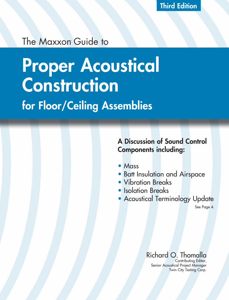
The Maxxon® Guide to
Proper Acoustical Constructionfor Floor/Ceiling Assemblies
For more information including sound test results:1-800-356-7887
E-mail: [email protected]
Maxxon® Corporation(formerly Gyp-Crete Corporation)
920 Hamel Road • P.O. Box 253 • Hamel, Minnesota 55340 USA 763-478-9600 • FAX: 763-478-2431
Rapid RadiantRapid Radiant
RESIDENTIAL
COMMERCIAL / SNOWMELTNEW LOW PROFILE
WARM FLOOR KIT
TM
Maxxon Underlayments and Acousti-Mat are but two components of an effective sound control system. No sound control system is better than its weakest component. Care must be taken in the installation of components of construction to assure the ultimate designed acoustical performance.
A Discussion of Sound Control Components including:
• Mass• Batt Insulation and Airspace• Vibration Breaks• Isolation Breaks• Acoustical Terminology Update
Printed 11/10 Item #60069 TA 502-6027
Third Edition
Ceramic Tile3⁄4" (19 mm) approved Maxxon® Underlayment
Acousti-Mat® LPR5/32" (3.97 mm)
Wood Subfloor
Parallel Chord Truss
Resillient Channel
5⁄8" (16 mm)Gypsum Board
Batt Insulation
www.MaxxonCorporation.com
What’s in Acoustical Terminology
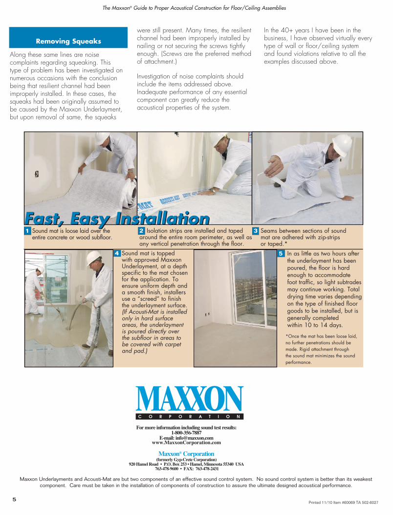
1 Sound mat is loose laid over the entire concrete or wood subfloor.
2 Isolation strips are installed and taped around the entire room perimeter, as well as any vertical penetration through the floor.
3 Seams between sections of sound mat are adhered with zip-strips or taped.*
Fast, Easy InstallationFast, Easy Installation
5 In as little as two hours after the underlayment has been poured, the floor is hard enough to accommodate foot traffic, so light subtrades may continue working. Total drying time varies depending on the type of finished floor goods to be installed, but is generally completed within 10 to 14 days.
*Once the mat has been loose laid, no further penetrations should be made. Rigid attachment through the sound mat minimizes the sound performance.
4 Sound mat is topped with approved Maxxon Underlayment, at a depth specific to the mat chosen for the application. To ensure uniform depth and a smooth finish, installers use a “screed” to finish the underlayment surface. (If Acousti-Mat is installed only in hard surface areas, the underlayment is poured directly over the subfloor in areas to be covered with carpet and pad.)
See Page 4.
5 4
Removing Squeaks
ACo
usti
-mAt®
LPR
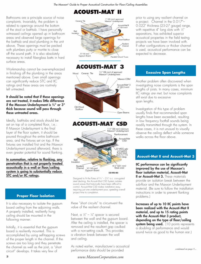
Bathrooms are a principle source of noise complaints. Invariably, the problem is related to openings around the bottom of the stool or bathtub. I have personally witnessed ceilings opened up in bathroom areas and observed large openings for the bathtub and stool plumbing in the unit above. These openings must be packed with plumbers putty or mortite to close off the sound path. It is also absolutely necessary to install fiberglass batts in hard surface areas.
Workmanship cannot be over-emphasized in finishing off the plumbing in the areas mentioned above. Even small openings can significantly reduce STC and IIC ratings and these areas are routinely left untreated.
It should be noted that if these openings are not treated, it makes little difference if the Maxxon Underlayment is 3⁄4" or 3" thick because sound will pass through these untreated areas.
Ideally, bathtubs and stools should be set on top of a completed floor, i.e.: If Maxxon Underlayment is the final layer of the floor system, it should be poured throughout the entire bathroom area, and the fixtures set on top. If the fixtures are installed first and the Maxxon Underlayment poured afterward, there is even greater potential for sound flanking.
In summation, relative to flanking, any penetration that is not properly treated acoustically in a wall or floor/ceiling system is going to substantially reduce STC and/or IIC ratings.
It is also necessary to isolate the gypsum board ceiling from the adjoining walls. A properly installed, resiliently hung ceiling should be mounted in the following manner:
Initially, it is essential that the gypsum board is resiliently mounted. This is accomplished by using self-tapping screws of the proper length in the channel. If the screws are too long and they penetrate the channel as well as the joist, a “short circuit” develops. It takes very few of
these “short circuits” to circumvent the value of the resilient channel.
Next, a 1⁄8" – 1⁄4" spacer is secured between the wall and the gypsum board. After the ceiling is installed, the spacer is removed and the resultant gap caulked with a non-setting caulk. This provides a vibration break between the wall and ceiling.
As noted earlier, manufacturer’s acoustical performance data should be provided
prior to using any resilient channel on a project. Channel in the 0.017"– 0.022" thickness (25-27 gauge) range, with repetitive 4" long slots with 1⁄2" separations, has exhibited superior acoustical properties in the field testing projects we have been involved with. If other configurations or thicker channel is used, acoustical performance can be expected to decrease.
Another problem often discovered when investigating noise complaints is the span lengths of joists. In many cases, minimum IIC ratings are met, but noise complaints still exist due to excessive span lengths.
Investigation of this type of problem usually finds that recommended span lengths have been exceeded, resulting in low frequency footfall sounds being readily transmitted through the system. In these cases, it is not unusual to visually observe the ceiling deflect while someone walks across the floor above.
IIC performance can be significantly improved by the use of Maxxon’s floor isolation material, Acousti-Mat II or Acousti-Mat 3. These materials provide an isolation break between the sub-floor and the Maxxon Underlayment material. (Be sure to follow the installation instructions in order to prevent flanking problems.)
Increases of up to 10 IIC points have been realized with the Acousti-Mat II material, and up to 15 rating points with the Acousti-Mat 3 product, depending on the type of floor/ceiling system being used. (10 points represents a doubling of performance and would sound twice as good to the human ear.)
The Mass Law basically states that if the mass or weight is doubled, an increase of 6 dB in TL (Transmission Loss) will be realized which is directly related to the STC ratings as well.
Using the above weight and the Mass Law formula, the estimated STC rating calculates out to be 48. (Actual published ratings on this system are in the 50 STC range, which is no doubt correct as the Mass Law does not account for cavity absorption [R-11 fiberglass]).
If the 3⁄4" Maxxon Underlayment was increased to 1" thick the weight of the system would increase to 17.3 PSF, which would raise the STC to a calculated 49.
Carrying this one step further to 11⁄2" thick, the weight of the above system would increase to 21.6 PSF, which raises the STC to a 51 (R-11 would increase this value to the 53-54 range).
Along these same lines, the density of the Maxxon Underlayment has only a marginal effect on the STC rating. This is for the same reason as above. For instance, 3⁄4" – 105 PCF Maxxon Underlayment weighs 6.6 PSF, while 3⁄4" thick 115 PCF Maxxon Underlayment weighs 7.2 PSF. The weight difference of 0.6 PSF is not sufficient to change the STC rating of the system.
It should be noted that although Maxxon Underlayment is an essential component of a floor/ceiling system relative to STC performance, it provides very little increase in IIC performance. The remainder of the components in the above example all play significant roles in providing satisfactory IIC ratings. Addressing the items from top down we have:
The plywood sub-floor and the 2" x 10" wood joists provide mass and stiffness to the system. It is extremely important when using 2" x 10"s that the recommended span length not be exceeded. The quality of the lumber is also important as well as proper blocking and workmanship.
The 31⁄2" thick unfaced fiberglass provides sound absorption in the joist spaces which helps absorb sound waves as they pass through the system.
It should be noted that sound absorptive material is very important within the joist cavity, but there is a law of diminishing returns. In other words, doubling the thickness of insulation will not double the degree of improvement realized from the initial thickness.
In some cases, adding too much insulation can actually have a negative effect on both STC and IIC performance. This is especially true with “blown” in products where thickness is difficult to control.
It is important to have some “dead air-space” within the joist cavity to ensure a vibration break exists between the sub-floor and ceiling.
The resilient channel is also a very significant part of the system both for STC and IIC. It effectively de-couples the ceiling from the joists therefore creating a vibration break. In recent years, there have been a number of resilient channels appear on the market that vary considerably in performance. For this reason, it is imperative that proper channel be used in the various floor/ceiling and wall systems. We have observed that channel in the 0.017"– 0.022" thickness (25-27 gauge) range with repetitive 4" long slots with 1⁄2" separations performs the best.
Heavier gauge does not constitute better acoustical performance — in fact the opposite holds true.
The combination of resilient channel and fiberglass is very effective when used together. One without the other is not nearly as efficient.
The 5⁄8" gypsum board is also significant as it completes the cavity which results in a nominal 10" air space. Dead air is an effective method of increasing STC and IIC performance, although fiberglass insulation further enhances the performance of the air space. It (gypsum board) also provides a dead load which is necessary for the resilient channel to work properly and further increases the mass of the system.
In summation, all components in a floor/ceiling system are essential and necessary in order to have an effective acoustical construction.e
In addition to the need for all components to work together, it is necessary to reduce or eliminate flanking paths. This term refers to any sound path around the building element. Examples of flanking paths are recessed light fixtures, openings around furnace ducts, plumbing runs, wall/floor junctions that are not caulked, sprinkler heads and the list goes on.
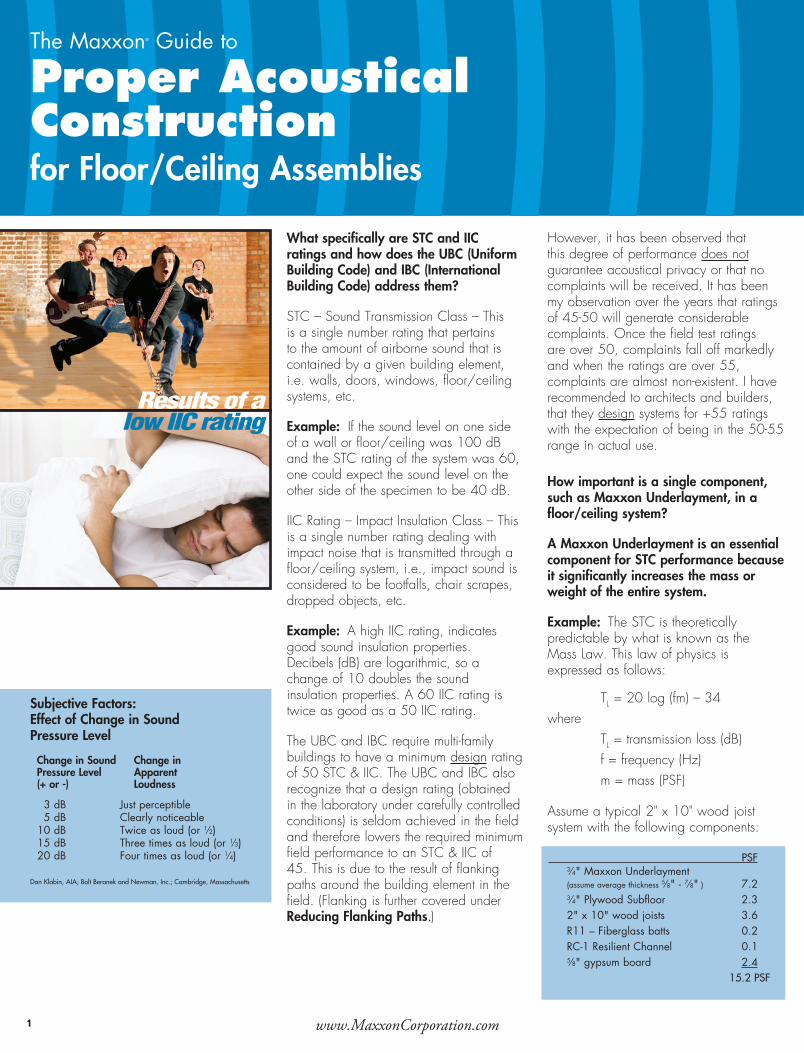
What specifically are STC and IIC ratings and how does the UBC (Uniform Building Code) and IBC (International Building Code) address them?
STC – Sound Transmission Class – This is a single number rating that pertains to the amount of airborne sound that is contained by a given building element, i.e. walls, doors, windows, floor/ceiling systems, etc.
Example: If the sound level on one side of a wall or floor/ceiling was 100 dB and the STC rating of the system was 60, one could expect the sound level on the other side of the specimen to be 40 dB.
IIC Rating – Impact Insulation Class – This is a single number rating dealing with impact noise that is transmitted through a floor/ceiling system, i.e., impact sound is considered to be footfalls, chair scrapes, dropped objects, etc.
Example: A high IIC rating, indicates good sound insulation properties. Decibels (dB) are logarithmic, so a change of 10 doubles the sound insulation properties. A 60 IIC rating is twice as good as a 50 IIC rating.
The UBC and IBC require multi-family buildings to have a minimum design rating of 50 STC & IIC. The UBC and IBC also recognize that a design rating (obtained in the laboratory under carefully controlled conditions) is seldom achieved in the field and therefore lowers the required minimum field performance to an STC & IIC of 45. This is due to the result of flanking paths around the building element in the field. (Flanking is further covered under Reducing Flanking Paths.)
However, it has been observed that this degree of performance does not guarantee acoustical privacy or that no complaints will be received. It has been my observation over the years that ratings of 45-50 will generate considerable complaints. Once the field test ratings are over 50, complaints fall off markedly and when the ratings are over 55, complaints are almost non-existent. I have recommended to architects and builders, that they design systems for +55 ratings with the expectation of being in the 50-55 range in actual use.
How important is a single component, such as Maxxon Underlayment, in a floor/ceiling system?
A Maxxon Underlayment is an essential component for STC performance because it significantly increases the mass or weight of the entire system.
Example: The STC is theoretically predictable by what is known as the Mass Law. This law of physics is expressed as follows:
TL = 20 log (fm) – 34where TL = transmission loss (dB) f = frequency (Hz) m = mass (PSF)
Assume a typical 2" x 10" wood joist system with the following components:
The Maxxon® Guide to Proper Acoustical Construction for Floor/Ceiling Assemblies
PSF 3⁄4" Maxxon Underlayment (assume average thickness 5⁄8" - 7⁄8" ) 7.2 3⁄4" Plywood Subfloor 2.3 2" x 10" wood joists 3.6 R11 – Fiberglass batts 0.2 RC-1 Resilient Channel 0.1 5⁄8" gypsum board 2.4 15.2 PSF
www.MaxxonCorporation.com
The Maxxon® Guide to Proper Acoustical Construction for Floor/Ceiling Assemblies
www.MaxxonCorporation.com
The Maxxon® Guide to Proper Acoustical Construction for Floor/Ceiling Assemblies
5⁄8" (16 mm) Gypsum Board
BattInsulation
1" (25 mm) approvedMaxxon® Underlayment
Acousti-Mat®II1⁄4" (6.4 mm)
Wood Subfloor
Parallel Chord Truss
ResilientChannel
Ceramic Tile
ACousti-mAt®
ii
Results of alow IIC rating
Subjective Factors:Effect of Change in Sound Pressure Level
Change in Sound Change in Pressure Level Apparent (+ or -) Loudness
3 dB Just perceptible 5 dB Clearly noticeable 10 dB Twice as loud (or 1⁄2) 15 dB Three times as loud (or 1⁄3) 20 dB Four times as loud (or 1⁄4)
Dan Klabin, AIA; Bolt Beranek and Newman, Inc.; Cambridge, Massachusetts
Mass Isolation Break
Mass
Vibration Break
Batt Insulation and Airspace
Sound Control Components
continued on page 5...
www.MaxxonCorporation.com1 2 3
ACousti-mAt®
3
ACousti-mAt®
CsD
11⁄2 " (38 mm) of approved Maxxon® Underlayment
Acousti-Mat® 3.8" (20.3 mm)
Open Beams
Old Wood Subfloor
Wood Ceramic Tile
Maxxon CSM
Resilient Channel
Acousti-MatCSD
Reinforcement
Batt Insulation
5⁄8" (16 mm) Gypsum Board
22 MSG galv corrugated fluted steel
deck 9⁄16" (15 mm) deep
1-1⁄2" (38 mm) minimum Maxxon® Underlayment
1 1⁄2 "
9-1⁄4" (231 mm) Steel Joist
CSD-MXU-003Only One Piece of the Puzzle
Reducing Flanking Paths
Proper Floor Isolation
Exessive Span Lengths
Acousti-Mat II and Acousti-Mat 3
Designed to fit the flutes of 9⁄16" – 21⁄2" o.c. corrugated steel decking, the Acousti-Mat CSD System isolates sound waves that historically have been difficult to control. Acousti-Mat CSD makes installation easy, requiring just one underlayment pour, speeding overall project time to completion.

Bathrooms are a principle source of noise complaints. Invariably, the problem is related to openings around the bottom of the stool or bathtub. I have personally witnessed ceilings opened up in bathroom areas and observed large openings for the bathtub and stool plumbing in the unit above. These openings must be packed with plumbers putty or mortite to close off the sound path. It is also absolutely necessary to install fiberglass batts in hard surface areas.
Workmanship cannot be over-emphasized in finishing off the plumbing in the areas mentioned above. Even small openings can significantly reduce STC and IIC ratings and these areas are routinely left untreated.
It should be noted that if these openings are not treated, it makes little difference if the Maxxon Underlayment is 3⁄4" or 3" thick because sound will pass through these untreated areas.
Ideally, bathtubs and stools should be set on top of a completed floor, i.e.: If Maxxon Underlayment is the final layer of the floor system, it should be poured throughout the entire bathroom area, and the fixtures set on top. If the fixtures are installed first and the Maxxon Underlayment poured afterward, there is even greater potential for sound flanking.
In summation, relative to flanking, any penetration that is not properly treated acoustically in a wall or floor/ceiling system is going to substantially reduce STC and/or IIC ratings.
It is also necessary to isolate the gypsum board ceiling from the adjoining walls. A properly installed, resiliently hung ceiling should be mounted in the following manner:
Initially, it is essential that the gypsum board is resiliently mounted. This is accomplished by using self-tapping screws of the proper length in the channel. If the screws are too long and they penetrate the channel as well as the joist, a “short circuit” develops. It takes very few of
these “short circuits” to circumvent the value of the resilient channel.
Next, a 1⁄8" – 1⁄4" spacer is secured between the wall and the gypsum board. After the ceiling is installed, the spacer is removed and the resultant gap caulked with a non-setting caulk. This provides a vibration break between the wall and ceiling.
As noted earlier, manufacturer’s acoustical performance data should be provided
prior to using any resilient channel on a project. Channel in the 0.017"– 0.022" thickness (25-27 gauge) range, with repetitive 4" long slots with 1⁄2" separations, has exhibited superior acoustical properties in the field testing projects we have been involved with. If other configurations or thicker channel is used, acoustical performance can be expected to decrease.
Another problem often discovered when investigating noise complaints is the span lengths of joists. In many cases, minimum IIC ratings are met, but noise complaints still exist due to excessive span lengths.
Investigation of this type of problem usually finds that recommended span lengths have been exceeded, resulting in low frequency footfall sounds being readily transmitted through the system. In these cases, it is not unusual to visually observe the ceiling deflect while someone walks across the floor above.
IIC performance can be significantly improved by the use of Maxxon’s floor isolation material, Acousti-Mat II or Acousti-Mat 3. These materials provide an isolation break between the sub-floor and the Maxxon Underlayment material. (Be sure to follow the installation instructions in order to prevent flanking problems.)
Increases of up to 10 IIC points have been realized with the Acousti-Mat II material, and up to 15 rating points with the Acousti-Mat 3 product, depending on the type of floor/ceiling system being used. (10 points represents a doubling of performance and would sound twice as good to the human ear.)
The Mass Law basically states that if the mass or weight is doubled, an increase of 6 dB in TL (Transmission Loss) will be realized which is directly related to the STC ratings as well.
Using the above weight and the Mass Law formula, the estimated STC rating calculates out to be 48. (Actual published ratings on this system are in the 50 STC range, which is no doubt correct as the Mass Law does not account for cavity absorption [R-11 fiberglass]).
If the 3⁄4" Maxxon Underlayment was increased to 1" thick the weight of the system would increase to 17.3 PSF, which would raise the STC to a calculated 49.
Carrying this one step further to 11⁄2" thick, the weight of the above system would increase to 21.6 PSF, which raises the STC to a 51 (R-11 would increase this value to the 53-54 range).
Along these same lines, the density of the Maxxon Underlayment has only a marginal effect on the STC rating. This is for the same reason as above. For instance, 3⁄4" – 105 PCF Maxxon Underlayment weighs 6.6 PSF, while 3⁄4" thick 115 PCF Maxxon Underlayment weighs 7.2 PSF. The weight difference of 0.6 PSF is not sufficient to change the STC rating of the system.
It should be noted that although Maxxon Underlayment is an essential component of a floor/ceiling system relative to STC performance, it provides very little increase in IIC performance. The remainder of the components in the above example all play significant roles in providing satisfactory IIC ratings. Addressing the items from top down we have:
The plywood sub-floor and the 2" x 10" wood joists provide mass and stiffness to the system. It is extremely important when using 2" x 10"s that the recommended span length not be exceeded. The quality of the lumber is also important as well as proper blocking and workmanship.
The 31⁄2" thick unfaced fiberglass provides sound absorption in the joist spaces which helps absorb sound waves as they pass through the system.
It should be noted that sound absorptive material is very important within the joist cavity, but there is a law of diminishing returns. In other words, doubling the thickness of insulation will not double the degree of improvement realized from the initial thickness.
In some cases, adding too much insulation can actually have a negative effect on both STC and IIC performance. This is especially true with “blown” in products where thickness is difficult to control.
It is important to have some “dead air-space” within the joist cavity to ensure a vibration break exists between the sub-floor and ceiling.
The resilient channel is also a very significant part of the system both for STC and IIC. It effectively de-couples the ceiling from the joists therefore creating a vibration break. In recent years, there have been a number of resilient channels appear on the market that vary considerably in performance. For this reason, it is imperative that proper channel be used in the various floor/ceiling and wall systems. We have observed that channel in the 0.017"– 0.022" thickness (25-27 gauge) range with repetitive 4" long slots with 1⁄2" separations performs the best.
Heavier gauge does not constitute better acoustical performance — in fact the opposite holds true.
The combination of resilient channel and fiberglass is very effective when used together. One without the other is not nearly as efficient.
The 5⁄8" gypsum board is also significant as it completes the cavity which results in a nominal 10" air space. Dead air is an effective method of increasing STC and IIC performance, although fiberglass insulation further enhances the performance of the air space. It (gypsum board) also provides a dead load which is necessary for the resilient channel to work properly and further increases the mass of the system.
In summation, all components in a floor/ceiling system are essential and necessary in order to have an effective acoustical construction.e
In addition to the need for all components to work together, it is necessary to reduce or eliminate flanking paths. This term refers to any sound path around the building element. Examples of flanking paths are recessed light fixtures, openings around furnace ducts, plumbing runs, wall/floor junctions that are not caulked, sprinkler heads and the list goes on.
What specifically are STC and IIC ratings and how does the UBC (Uniform Building Code) and IBC (International Building Code) address them?
STC – Sound Transmission Class – This is a single number rating that pertains to the amount of airborne sound that is contained by a given building element, i.e. walls, doors, windows, floor/ceiling systems, etc.
Example: If the sound level on one side of a wall or floor/ceiling was 100 dB and the STC rating of the system was 60, one could expect the sound level on the other side of the specimen to be 40 dB.
IIC Rating – Impact Insulation Class – This is a single number rating dealing with impact noise that is transmitted through a floor/ceiling system, i.e., impact sound is considered to be footfalls, chair scrapes, dropped objects, etc.
Example: A high IIC rating, indicates good sound insulation properties. Decibels (dB) are logarithmic, so a change of 10 doubles the sound insulation properties. A 60 IIC rating is twice as good as a 50 IIC rating.
The UBC and IBC require multi-family buildings to have a minimum design rating of 50 STC & IIC. The UBC and IBC also recognize that a design rating (obtained in the laboratory under carefully controlled conditions) is seldom achieved in the field and therefore lowers the required minimum field performance to an STC & IIC of 45. This is due to the result of flanking paths around the building element in the field. (Flanking is further covered under Reducing Flanking Paths.)
However, it has been observed that this degree of performance does not guarantee acoustical privacy or that no complaints will be received. It has been my observation over the years that ratings of 45-50 will generate considerable complaints. Once the field test ratings are over 50, complaints fall off markedly and when the ratings are over 55, complaints are almost non-existent. I have recommended to architects and builders, that they design systems for +55 ratings with the expectation of being in the 50-55 range in actual use.
How important is a single component, such as Maxxon Underlayment, in a floor/ceiling system?
A Maxxon Underlayment is an essential component for STC performance because it significantly increases the mass or weight of the entire system.
Example: The STC is theoretically predictable by what is known as the Mass Law. This law of physics is expressed as follows:
TL = 20 log (fm) – 34where TL = transmission loss (dB) f = frequency (Hz) m = mass (PSF)
Assume a typical 2" x 10" wood joist system with the following components:
The Maxxon® Guide to Proper Acoustical Construction for Floor/Ceiling Assemblies
PSF 3⁄4" Maxxon Underlayment (assume average thickness 5⁄8" - 7⁄8" ) 7.2 3⁄4" Plywood Subfloor 2.3 2" x 10" wood joists 3.6 R11 – Fiberglass batts 0.2 RC-1 Resilient Channel 0.1 5⁄8" gypsum board 2.4 15.2 PSF
www.MaxxonCorporation.com
The Maxxon® Guide to Proper Acoustical Construction for Floor/Ceiling Assemblies
www.MaxxonCorporation.com
The Maxxon® Guide to Proper Acoustical Construction for Floor/Ceiling Assemblies
5⁄8" (16 mm) Gypsum Board
BattInsulation
1" (25 mm) approvedMaxxon® Underlayment
Acousti-Mat®II1⁄4" (6.4 mm)
Wood Subfloor
Parallel Chord Truss
ResilientChannel
Ceramic Tile
ACousti-mAt®
ii
Results of alow IIC rating
Subjective Factors:Effect of Change in Sound Pressure Level
Change in Sound Change in Pressure Level Apparent (+ or -) Loudness
3 dB Just perceptible 5 dB Clearly noticeable 10 dB Twice as loud (or 1⁄2) 15 dB Three times as loud (or 1⁄3) 20 dB Four times as loud (or 1⁄4)
Dan Klabin, AIA; Bolt Beranek and Newman, Inc.; Cambridge, Massachusetts
Mass Isolation Break
Mass
Vibration Break
Batt Insulation and Airspace
Sound Control Components
continued on page 5...
www.MaxxonCorporation.com1 2 3
ACousti-mAt®
3
ACousti-mAt®
CsD
11⁄2 " (38 mm) of approved Maxxon® Underlayment
Acousti-Mat® 3.8" (20.3 mm)
Open Beams
Old Wood Subfloor
Wood Ceramic Tile
Maxxon CSM
Resilient Channel
Acousti-MatCSD
Reinforcement
Batt Insulation
5⁄8" (16 mm) Gypsum Board
22 MSG galv corrugated fluted steel
deck 9⁄16" (15 mm) deep
1-1⁄2" (38 mm) minimum Maxxon® Underlayment
1 1⁄2 "
9-1⁄4" (231 mm) Steel Joist
CSD-MXU-003Only One Piece of the Puzzle
Reducing Flanking Paths
Proper Floor Isolation
Exessive Span Lengths
Acousti-Mat II and Acousti-Mat 3
Designed to fit the flutes of 9⁄16" – 21⁄2" o.c. corrugated steel decking, the Acousti-Mat CSD System isolates sound waves that historically have been difficult to control. Acousti-Mat CSD makes installation easy, requiring just one underlayment pour, speeding overall project time to completion.

To date the International Building Code (IBC) and the Uniform Building Code (UBC) have not changed or added any new acoustical terminology or values. They both still only require 50 STC (45 F-STC) and 50 IIC (45 F-IIC). Codes, Covenants and Regulations (CC&R) can differ all across the country but now almost all have adopted the IBC.
The IBC only recognizes the acoustical terms STC, IIC, F-STC and F-IIC. However, the ASTM governing F-STC has changed slightly. The actual test method itself remains the same, but the ASTM has renamed F-STC (field sound transmission class) to A-STC (apparent sound transmission class). Some acoustical agencies are reporting this new name, A-STC, but some still report an F-STC. The actual number rating is one in the same. Therefore an A-STC test report can be used in place of an F-STC report to show compliance with code.
California — A Notable ExceptionCalifornia has state (California Building Code—CBC), city, county, and local code requirements for sound. The following are acoustical terms, definitions and respective abbreviations that you may encounter in California and other parts of North America.
• NIC (Noise Isolation Class) This is an airborne sound test done in occupied units with no normalization* of the receiving space (relates to STC)
• NNIC (Normalized Noise Isolation Class) This is an airborne sound test done in unoccupied units with normalization of the receiving space (relates to F-STC)
• ITC (Impact Transmission Class) This is an impact test done in occupied units with no normalization of the receiving space (relates to IIC)
• NITC (Normalized Impact Transmission Class) This is an impact test done in unoccupied units with normalization of the receiving space (relates to F-IIC)
*The purpose of normalization is to remove the effects of the receiving space’s sound absorption from the results. For example, a room with a mattress and carpet has different sound absorption properties than an empty room and therefore, will sound different. The current standards require normalization for impact testing (IIC) and airborne testing (STC).
Explaining Delta IICASTM has a new standard test method, ASTM E 2179 “Laboratory Measurement of the Effectiveness of Floor Coverings in Reducing Impact Sound Transmission Through Concrete Floors.” The acoustical unit of measure that results from this test is “Delta IIC”. Basically this lab test uses a standard 6" concrete slab with no ceiling. The slab is tested bare as with IIC, then flooring, toppings, sound mats are tested on the same slab for IIC. Delta IIC is derived by subtracting the IIC of the 6" bare concrete from the IIC of the arious tested assemblies. The higher the Delta IIC, the higher the performance level.
Delta IIC testing and terminology will evolve around concrete slabs and will have nothing to do with wood frame acoustics.
Acousti-Mat LP (Low Profile) Sound Control SystemMaxxon’s Acousti-Mat LP (Low Profile) system can meet the 50 IIC sound control rating required by the International Building Code, before any floor goods are installed. The Acousti-Mat LP is attached to the concrete subfloor, then topped with a Maxxon Underlayment. The Acousti-Mat LP is permanently encased in the underlayment, so when floor goods are changed, the sound control system remains intact. The underlayment can even level the floor to meet the 1⁄8" in 10 feet levelness criteria required for laminate wood floors. The Acousti-Mat LP system achieved a Delta IIC of 19, that’s approximately a 75% reduction in impact noise on concrete floor systems.
Acousti-Mat LPR (Low Profile with Reinforcement) Sound Control SystemIdeal for wood frame apartment construction, Acousti-Mat LPR can also be used in mixed use, single family, condominiums, mid-rise, and high-rise construction.
Acousti-Mat LPR maintains a low 3⁄4" profile when covered with a Maxxon Underlayment in wood frame construction, and tile can also be thin-set directly to this sound mat in concrete construction or when used over a Maxxon Underlayment. Acousti-Mat LPR systems have over 100 UL Fire Designs, making it an ideal choice for sound control in apartment construction.
Along these same lines are noise complaints regarding squeaking. This type of problem has been investigated on numerous occasions with the conclusion being that resilient channel had been improperly installed. In these cases, the squeaks had been originally assumed to be caused by the Maxxon Underlayment, but upon removal of same, the squeaks
were still present. Many times, the resilient channel had been improperly installed by nailing or not securing the screws tightly enough. (Screws are the preferred method of attachment.)
Investigation of noise complaints should include the items addressed above. Inadequate performance of any essential component can greatly reduce the acoustical properties of the system.
In the 40+ years I have been in the business, I have observed virtually every type of wall or floor/ceiling system and found violations relative to all the examples discussed above.
The Maxxon® Guide to Proper Acoustical Construction for Floor/Ceiling AssembliesThe Maxxon® Guide to Proper Acoustical Construction for Floor/Ceiling Assemblies
Richard O. ThomallaContributing Editor,
Senior Acoustical Project ManagerTwin City Testing Corp.
The Maxxon® Guide to
Proper Acoustical Constructionfor Floor/Ceiling Assemblies
For more information including sound test results:1-800-356-7887
E-mail: [email protected]
Maxxon® Corporation(formerly Gyp-Crete Corporation)
920 Hamel Road • P.O. Box 253 • Hamel, Minnesota 55340 USA 763-478-9600 • FAX: 763-478-2431
Rapid RadiantRapid Radiant
RESIDENTIAL
COMMERCIAL / SNOWMELTNEW LOW PROFILE
WARM FLOOR KIT
TM
Maxxon Underlayments and Acousti-Mat are but two components of an effective sound control system. No sound control system is better than its weakest component. Care must be taken in the installation of components of construction to assure the ultimate designed acoustical performance.
A Discussion of Sound Control Components including:
• Mass• Batt Insulation and Airspace• Vibration Breaks• Isolation Breaks• Acoustical Terminology Update
Printed 11/10 Item #60069 TA 502-6027
Third Edition
Ceramic Tile3⁄4" (19 mm) approved Maxxon® Underlayment
Acousti-Mat® LPR5/32" (3.97 mm)
Wood Subfloor
Parallel Chord Truss
Resillient Channel
5⁄8" (16 mm)Gypsum Board
Batt Insulation
www.MaxxonCorporation.com
What’s in Acoustical Terminology
1 Sound mat is loose laid over the entire concrete or wood subfloor.
2 Isolation strips are installed and taped around the entire room perimeter, as well as any vertical penetration through the floor.
3 Seams between sections of sound mat are adhered with zip-strips or taped.*
Fast, Easy InstallationFast, Easy Installation
5 In as little as two hours after the underlayment has been poured, the floor is hard enough to accommodate foot traffic, so light subtrades may continue working. Total drying time varies depending on the type of finished floor goods to be installed, but is generally completed within 10 to 14 days.
*Once the mat has been loose laid, no further penetrations should be made. Rigid attachment through the sound mat minimizes the sound performance.
4 Sound mat is topped with approved Maxxon Underlayment, at a depth specific to the mat chosen for the application. To ensure uniform depth and a smooth finish, installers use a “screed” to finish the underlayment surface. (If Acousti-Mat is installed only in hard surface areas, the underlayment is poured directly over the subfloor in areas to be covered with carpet and pad.)
See Page 4.
5 4
Removing Squeaks
ACo
usti
-mAt®
LPR