Embed Size (px)
Citation preview
When bits get wet: introduction to microfluidic networking
Andrea Zanella, Andrea Biral
Trinity College Dublin – 8 July, 2013
Most of experimental pictures in this presentations are complimentary from Prof. Mistura (Univ. of Padova)This work was funded by the University of Padova through the MiNET university project, 2012

2
Purposes
1. Quick introduction to the microfluidic area
2. Exemplify some of the problems that arise when dealing with microfluidic networks
3. Providing an idea of the possible research challenges that are waiting for you!
4. Growing the interest on the subject… to increase my citation index!

WHAT IS IT ALL ABOUT?
3
4
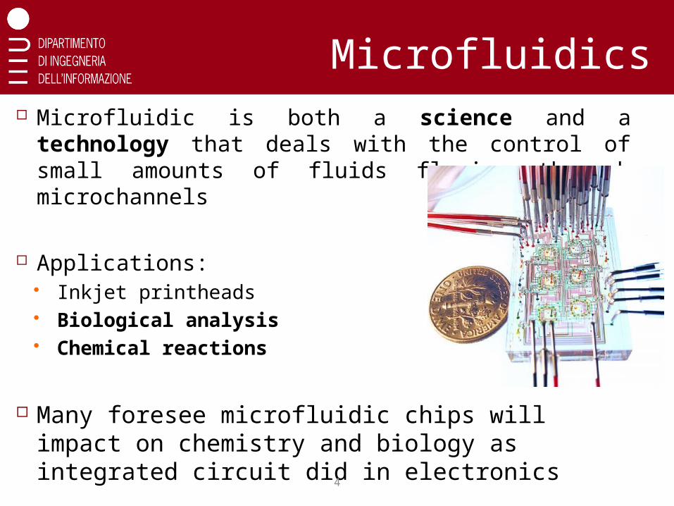
Microfluidic is both a science and a technology that deals with the control of small amounts of fluids flowing through microchannels
Applications: Inkjet printheads Biological analysis Chemical reactions
Many foresee microfluidic chips will impact on chemistry and biology as integrated circuit did in electronics
Microfluidics

5
Advantages in fluidic miniaturization
Portability
Optimum flow control Accurate control of
concentrations and
molecular interactions
Very small quantities
of reagents Reduced times for analysis
and synthesis
Reduced chemical waste

6
Popularity
7
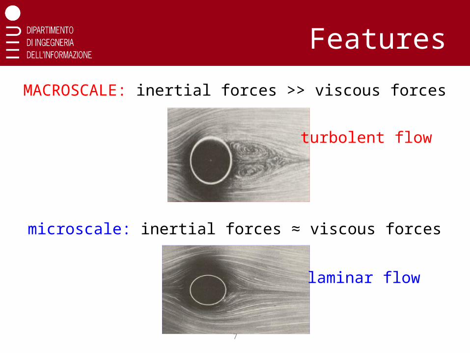
Features
MACROSCALE: inertial forces >> viscous forces
turbolent flow
microscale: inertial forces ≈ viscous forces
laminar flow
8
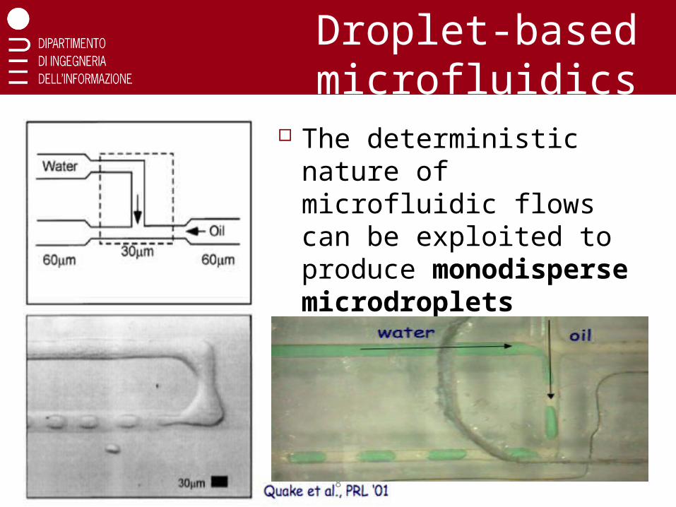
Droplet-based microfluidics
The deterministic nature of microfluidic flows can be exploited to produce monodisperse microdroplets
This is called squeezing regime
9
What’s microfluidic networking?
Current microfluidics devices are special purpose One device for each specific application
Next frontier: developing basic networking
modules for enabling flexible microfluidic
systems Versatility: multi-purpose system
Capabilities: LoCs can be interconnected to perform
multiple phases reactions
Costs: less reactants, less devices, lower costs
Enable flexible microfluidic systems using pure
passive hydrodynamic manipulation!
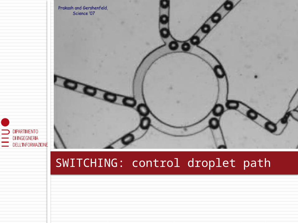
SWITCHING: control droplet path
11
Switching principle
Switching is based on 2 simple rules
1. At bifurcations, droplets always flow along the path with least instantaneous resistance
2. A droplet increases the resistance of the channel proportionally to its size
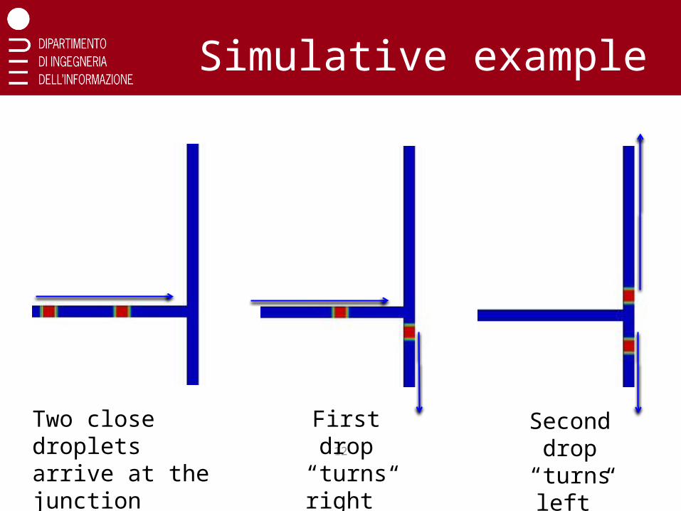
Simulative example
12
Two close droplets arrive at the junction
First drop “turns right”
Second drop “turns
left”
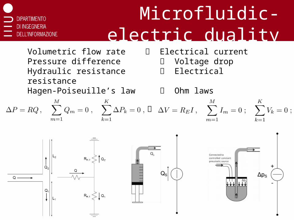
Microfluidic-electric duality
Volumetric flow rate Electrical currentPressure difference Voltage dropHydraulic resistance Electrical resistanceHagen-Poiseuille’s law Ohm laws
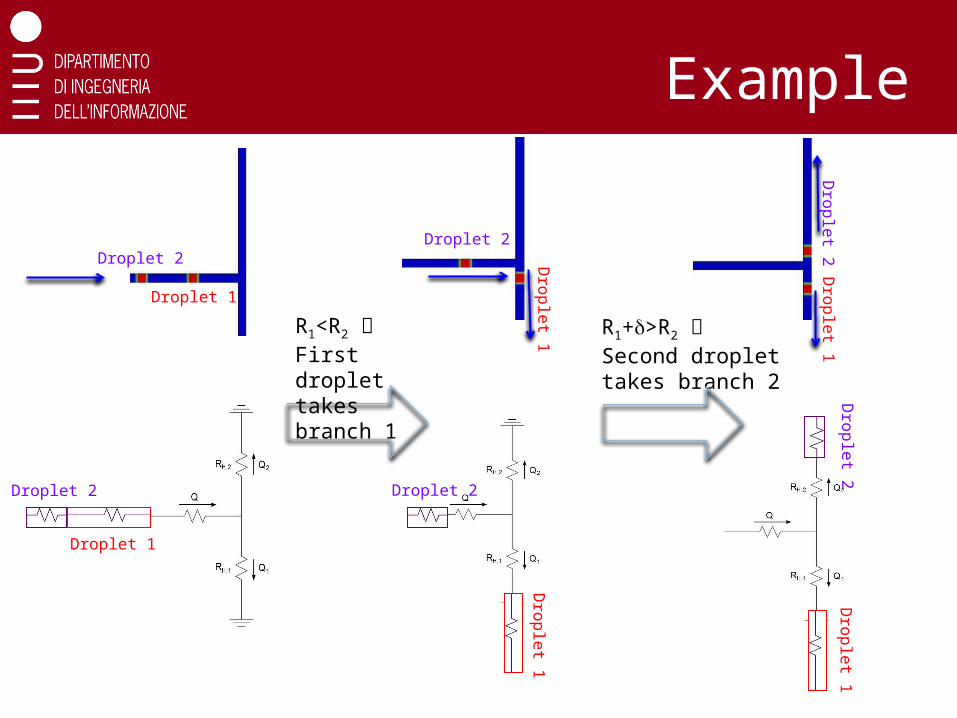
Example
Droplet 1
Droplet 2
Dro
ple
t 1
Droplet 2
Dro
ple
t 1D
rop
let 2
Droplet 1
Droplet 2
Dro
ple
t 1
Droplet 2
Dro
ple
t 1D
rop
let 2
R1<R2 First droplet takes branch 1
R1+d>R2 Second droplet takes branch 2
15
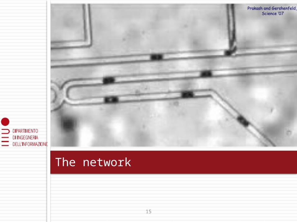
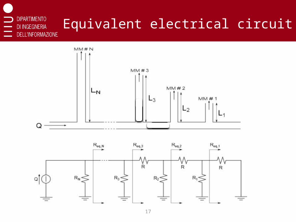
The network
16
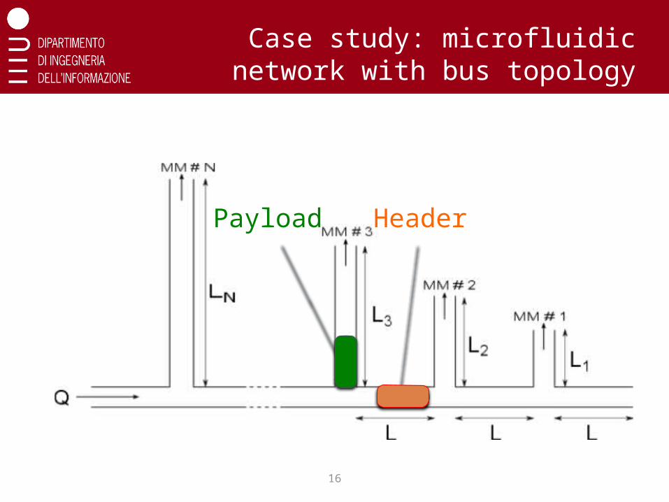
Case study: microfluidic network with bus topology
HeaderPayload
17
Equivalent electrical circuit

18
Topological constraints (I)
Header must always flow along the main
path:
Rn=aReq,n with a >1
Outlet branches closer to the source are
longer
expansion factor

19
Topological constraints (II)
Payload shall be deflected only into the target branch
Different targets require headers of different length
1st constraint on the value of the expansion factor a
MM #N
MM #1
MM #2
HeadersPayloads

20
Topological constraints (III)
Header must fit into the distance L between outlets
The header for Nth outlet must be shorter than L
Ln Ln-1 Ln-2
2nd constraint on the value of the expansion factor a
21
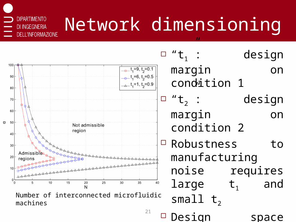
Network dimensioning “t1”: design margin
on condition 1 “t2”: design margin
on condition 2 Robustness to
manufacturing noise requires large t1 and small t2
Design space reduces as N grows
Number of interconnected microfluidic machines
22
Results
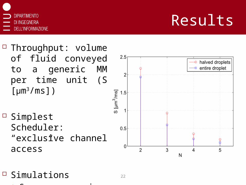
Throughput: volume of fluid conveyed to a generic MM per time unit (S [μm3/ms])
Simplest Scheduler: “exclusive channel access”
Simulations Squares: maximum
size payload droplet Circles: halved-size
payload droplets
23
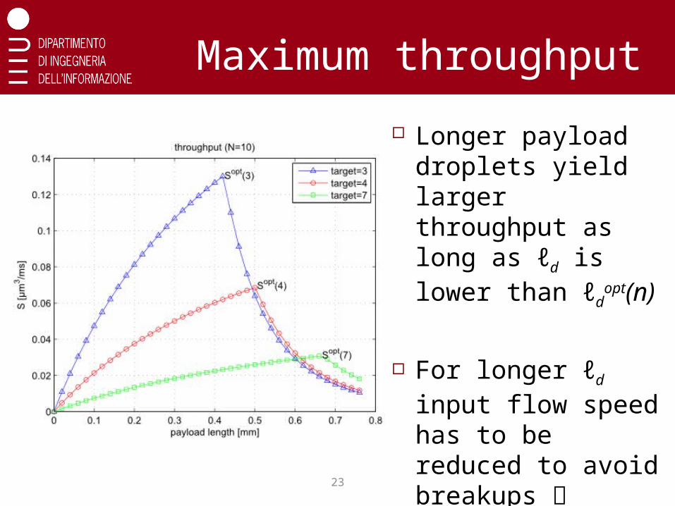
Maximum throughput
Longer payload droplets yield larger throughput as long as ℓd is lower than ℓd
opt(n)
For longer ℓd input flow speed has to be reduced to avoid breakups performance drops
24
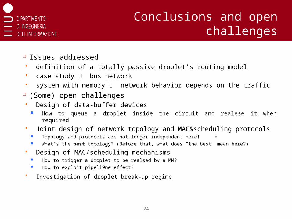
Conclusions and open challenges
Issues addressed definition of a totally passive droplet’s routing model case study bus network system with memory network behavior depends on the traffic
(Some) open challenges Design of data-buffer devices
How to queue a droplet inside the circuit and realese it when required Joint design of network topology and MAC&scheduling protocols
Topology and protocols are not longer independent here! What’s the best topology? (Before that, what does “the best” mean here?)
Design of MAC/scheduling mechanisms How to trigger a droplet to be realsed by a MM? How to exploit pipeli9ne effect?
Investigation of droplet break-up regime

When bits get wet: introduction to microfluidic networking
If we are short of time at this point… as it usually is,
just drop me an email!
Any questions?

26
Spare slides

27
Microfluidic bubble logic Recent discoveries prove that droplet
microfluidic systems can perform basic Boolean logic functions, such as AND, OR, NOT gates.
A B A+B
AB
1 0 1 0
0 1 1 0
1 1 1 1
28
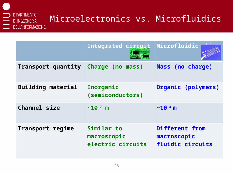
Microelectronics vs. Microfluidics
Integrated circuit Microfluidic chip
Transport quantity Charge (no mass) Mass (no charge)
Building material Inorganic (semiconductors)
Organic (polymers)
Channel size ~10-7 m ~10-4 m
Transport regime Similar to macroscopic electric circuits
Different from macroscopic fluidic circuits
29
Key elements
Source of data
Switching elements
Network topology
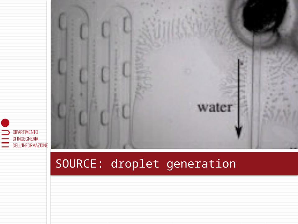
SOURCE: droplet generation
31
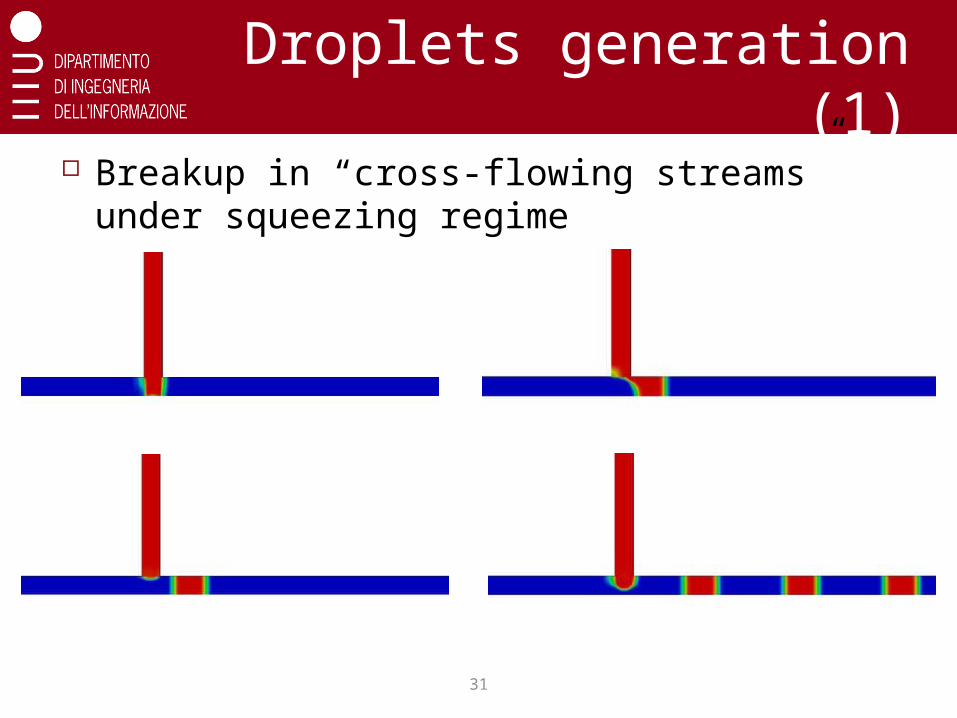
Droplets generation (1) Breakup in “cross-flowing streams” under
squeezing regime
32
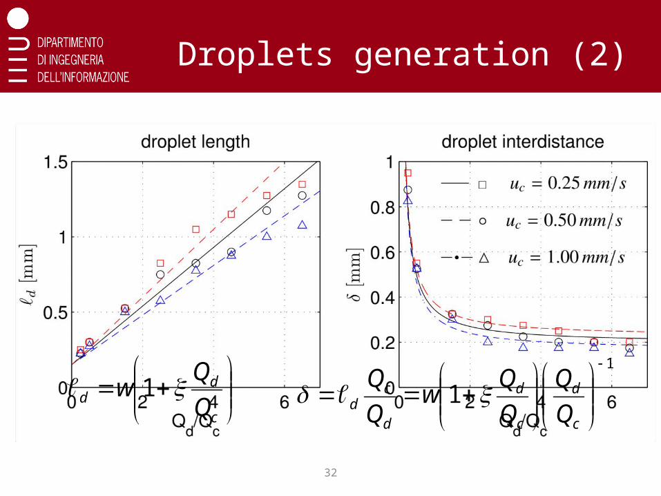
Droplets generation (2)
By changing input parameters, you can control droplets length and spacing, but NOT independently!
c
dd Q
Qw 1
1
1
c
d
c
d
d
cd Q
Q
Q
Qw
Q
Q
Junction breakup
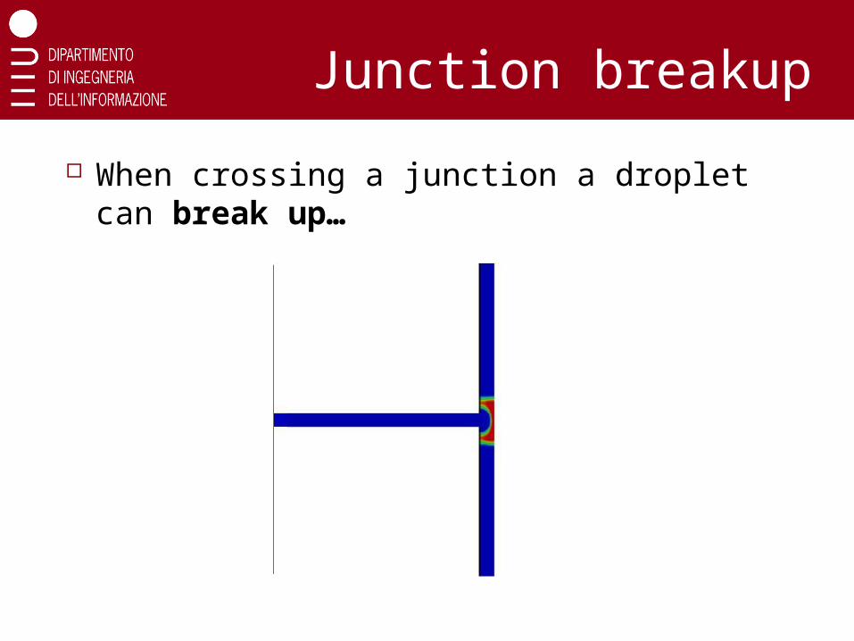
When crossing a junction a droplet can break up…
33

34
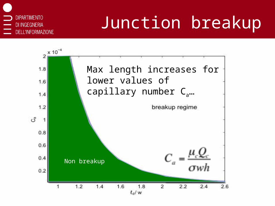
Junction breakup
To avoid breakup, droplets shall not be too long… [1]
[1]A. M. Leshansky, L. M. Pismen, “Breakup of drops in a microfluidic T-junction”, Phys. Fluids, 21.
35
Junction breakup
Max length increases for lower values of capillary number Ca…
Non breakup

36
Switching questions
What’s the resistance increase brought along by a droplet?
Is it enough to deviate the second droplet? Well… it depends on the original fluidic
resistance of the branches… To help sorting this out… an analogy with
electric circuit is at hand…
3
)(
wh
a dcdd
The longer the droplet, the larger the resistanceDynamic viscosity
37
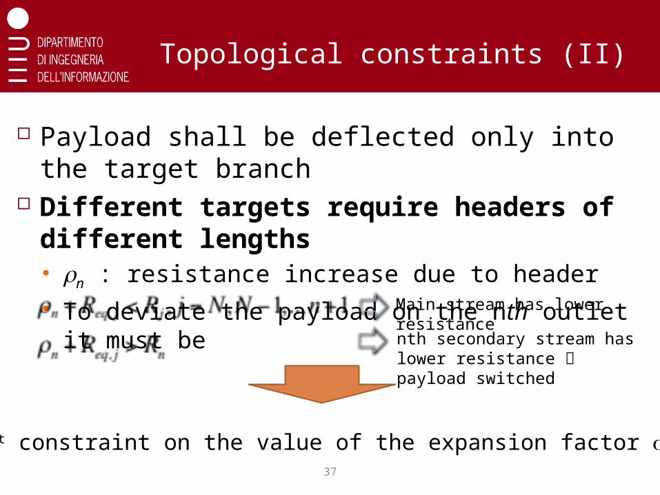
Topological constraints (II)
Payload shall be deflected only into the target branch
Different targets require headers of different lengths rn : resistance increase due to header To deviate the payload on the nth outlet it must
be
Main stream has lower resistance
nth secondary stream has lower resistance payload switched
1st constraint on the value of the expansion factor a

38
Topological constraints (III)
Header must fit into the distance L between outlets
Longest header for Nth outlet (closest to source)
Ln Ln-1 Ln-2
2nd constraint on the value of the expansion factor a