Embed Size (px)
Citation preview
To appear in Journal of the Society for Information Display, 2009
1
White LED Backlight Control for Motion Blur Reduction and Power Minimization in Large LCD TVs
Wonbok Lee, Kimish Patel, Massoud Pedram
University of Southern California Department of Electrical Engineering
Los Angeles CA 90089
Abstract- A 1-D LED backlight scanning and a 2-D local dimming technique for large LCD TVs are presented. These
techniques not only reduce the motion blur artifacts by means of impulse representation of images in video but also increase
the static contrast ratio by means of local dimming in the image(s). Both techniques exploit a unique feature of LED backlight
in large LCD TVs in which the whole panel is divided into a pre-defined number of regions such that the luminance in each
region is independently controllable. The proposed techniques are implemented in a Xilinx FPGA and demonstrated on a
Samsung 40-inch LCD TV. Measurement results show that the proposed techniques significantly reduce the motion blur
artifacts, enhance the static contrast ratio by about 3X, and reduce the power consumption by 10% on average.
Keywords- LED backlight, backlight scanning, backlight local dimming, motion blur, contrast ratio, low power.
1. Introduction
LCD (Liquid Crystal Display) TVs are the main stream products in the current FPD (Flat Panel Display) market and they are
present literally everywhere in our lives, e.g., living room, school/workplace, and grocery stores. In spite of their popularity
and excellent performance (e.g. vivid image representation and high native resolution) over the other types of TVs such as
PDP (Plasma Display Panel), LCDs suffer from a number of shortcomings such as motion blur artifact1 [1][2][3], low CR
(contrast ratio), and low brightness. For those reasons, CRT’s (Cathode Ray Tube) ‘motion blur free’ feature [4] and PDP’s
high CR feature pose continual threat to LCD’s dominance.
The biggest shortcoming of LCDs is the motion blur artifact due to three well-known phenomena: i) slow RT (response
time) of LC (Liquid Crystal), ii) scan-and-hold feature of LCDs, and iii) slow pursuit nature of the HVS (Human Visual
System). In order to overcome slow RT of LC, typically various kinds of over-driving techniques [5][6], are widely employed
by the LCD industry. Those over-driving techniques generally apply sufficiently high voltage levels to LCs so as to tilt them
1 Motion blur is the apparent streaking of rapidly moving objects in a still image or a sequence of images such as a movie.
To appear in Journal of the Society for Information Display, 2009
2
faster, i.e., consequently get them to respond faster. The amount of over-driving voltages is typically determined at design
time and saved in a LUT (look-up table).
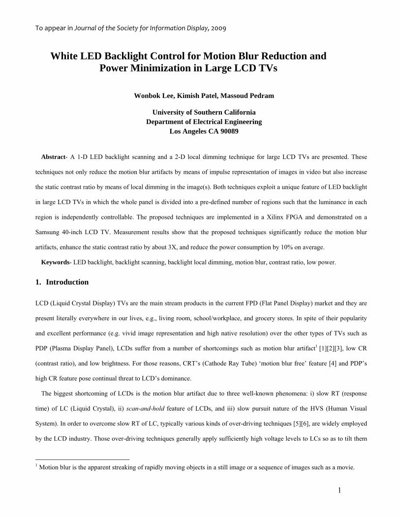
Furthermore to effectively tackle the scan-and-hold aspect of LCDs (illustrated in Fig. 1), together with the slow pursuit
nature of the HVS, LCD architects have devised various ‘eye-bleaching’ techniques such as BFI (black frame insertion),
backlight flashing/blinking, and backlight scanning [7][8][9][10]. In fact, although the response time may approach zero in
future LCDs, the motion blur artifact will continue to exist as long as the LCD panels display every image in the scan-and-
hold style. The aforementioned “fixes” attempt to re-create the impulse-type image display of CRT monitors in the LCD
panels so that the afterimages in an observer’s eyes are eliminated on a per frame basis.
Fig. 1 Hold-type image display in LCD vs. impulse-type image display in CRT.
Another shortcoming in LCDs is their relatively low CR compared to PDP. Contrast ratio is generally characterized in two
ways: i) static (or spatial) and ii) dynamic (or temporal). Static CR is defined as a (perceived) luminance difference between
the maximum and the minimum pixel values within an image frame whereas dynamic CR is defined as a luminance
difference between the maximum and the minimum pixel values across image frames.
As known, low CR in LCDs mainly originates from the backlight leak thru LC to the front side of the panel especially
when the pixel values are close to zero grayscale. One good solution to this problem is the dynamic dimming of the backlight,
which may be classified as follows: 1) 0-D (frame level) [11], 2) 1-D (line/segment level), and 3) 2-D (grid/tile level).
Relatively small LCDs, such as PC monitor, equipped with CCFL (Cold Cathode Florescent Lamp) backlight(s) simply
allows 0-D control while large LCDs, such as LCD TVs, allows 1-D control. In both cases, either a dynamic CR or a limited
range of static CR enhancements is merely feasible. True static CR enhancement is feasible only to the LCDs with 2-D
backlight modulation. The most popular backlight source, in this category, is the LED (Light Emitting Diode).
This paper presents two new backlight control techniques: a 1-D LED backlight scanning technique and a 2-D LED
backlight local dimming technique. The former reduces the motion blur artifact by effectively breaking the scan-and-hold
To appear in Journal of the Society for Information Display, 2009
3
feature of LCDs while the latter enhances the static CR. In both cases, along with quality enhancement, power savings are
achieved as well. The aforesaid techniques are completely independent of one another and hence can be easily combined
together. In this paper, however, we do not consider this combination.
The remainder of the paper is organized as follows. In section 2, previous backlight scaling works are reviewed. Section 3
explains the proposed two techniques following the detailed analysis of the impulse-type image display in CRTs as well as
the HVS. Section 4 shows the methodology and experimental results. Lastly, section 5 is the conclusion.
2. Background
2.1 Previous Work
Previous work on backlight control can be categorized into two classes: 1) Reducing the power dissipation within a given
budget of image/video quality distortion, 2) Enhancing the dynamic/static CR while maintaining the overall luminance of
image(s).
In the first class, Chang et al. [12] scaled down the backlight luminance while compensating the (perceived) image
luminance loss by increasing the pixel values using two different mechanisms; 1) backlight luminance dimming with
brightness compensation, 2) backlight luminance dimming with contrast enhancement. Cheng et al. [13] improved this simple
approach by eliminating the pixel-by-pixel transformation of the displayed image thru minor hardware modifications to the
built-in LCD reference driver. Their key idea was to first truncate the image histogram on both ends to obtain a smaller DR
(dynamic range) of the image pixel values and then to spread out the pixel values. Iranli et al. [14] proposed a novel method
for image transformation whereby the DR of the original image is reduced such that the incurred image distortion is no more
than a pre-specified value. Later, the same authors [15] extended their frame-sensitive backlight scaling works to the video
domain such that the expected video flickering is minimized by considering both of spatial and temporal distortions.
In the second class, Oh et al. [16] proposed an adaptive dimming with CCFL backlights, which enhanced the dynamic CR
by a factor of two. Greef et al. [17] proposed to combine the 1-D dimming and boosting of the CCFL backlights to improve
the brightness, static CR, and still save power. Recently, Chen et al. [18][19] presented an idea that incorporated 2-D LED
local dimming and global dimming, both of which aimed at eliminating front-side backlight leak thru LC pixels. Though their
idea is effective to minimize the light leak in the dark regions (hence, improve the black-level and the static CR), aiming at the
light leak minimization even at their global dimming results in the luminance degradation in the overall image.
More recently, various backlight scanning based ideas have been proposed, which basically modulate the duty cycle of the
To appear in Journal of the Society for Information Display, 2009
4
backlight source elements. Fisekovic et al. [20] proposed to consider parameters of i) proper timing, ii) number of backlight
segments, and iii) exposure time (i.e., duty cycle). They asserted that at least 6-7 segments and 25~30% of duty cycle is
effective in suppressing motion blur artifact while maintaining the reasonable brightness of the frame images. Hung et al. [21]
proposed to consider parameters of i) duty ratio, ii) lamp current, and 3) timing of CCFLs. Recently, Sluyterman et al. [22]
asserted a proper timing of backlight scanning in HCFL (Hot Cathode Fluorescent Lamp). Though their idea is novel, coarse
granularity and slow response of HCFL backlights makes their idea less attractive in practice. Greef et al. [23] combined the
backlight scanning, dimming and boosting techniques in HCFL backlights, which also has a similar limitation.
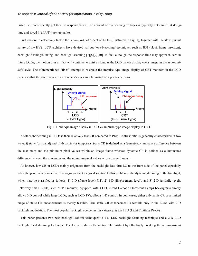
On this paper, we present two novel backlight control techniques. In addition,
The proposed techniques are implemented in a Full-HD 40” LCD TV equipped with white LED backlights (cf. Fig. 2).
Fig. 2 Test Environment and circuit blocks on the panel.
The proposed scanning technique balances the degree of motion blur reduction and luminance loss by determining the most
favorable backlight duty cycle.
In the proposed local dimming techniques, the reported power savings, together with the static CR enhancement, are
actually measured.
2.2 Circuit Architecture for LCD Panel Driving
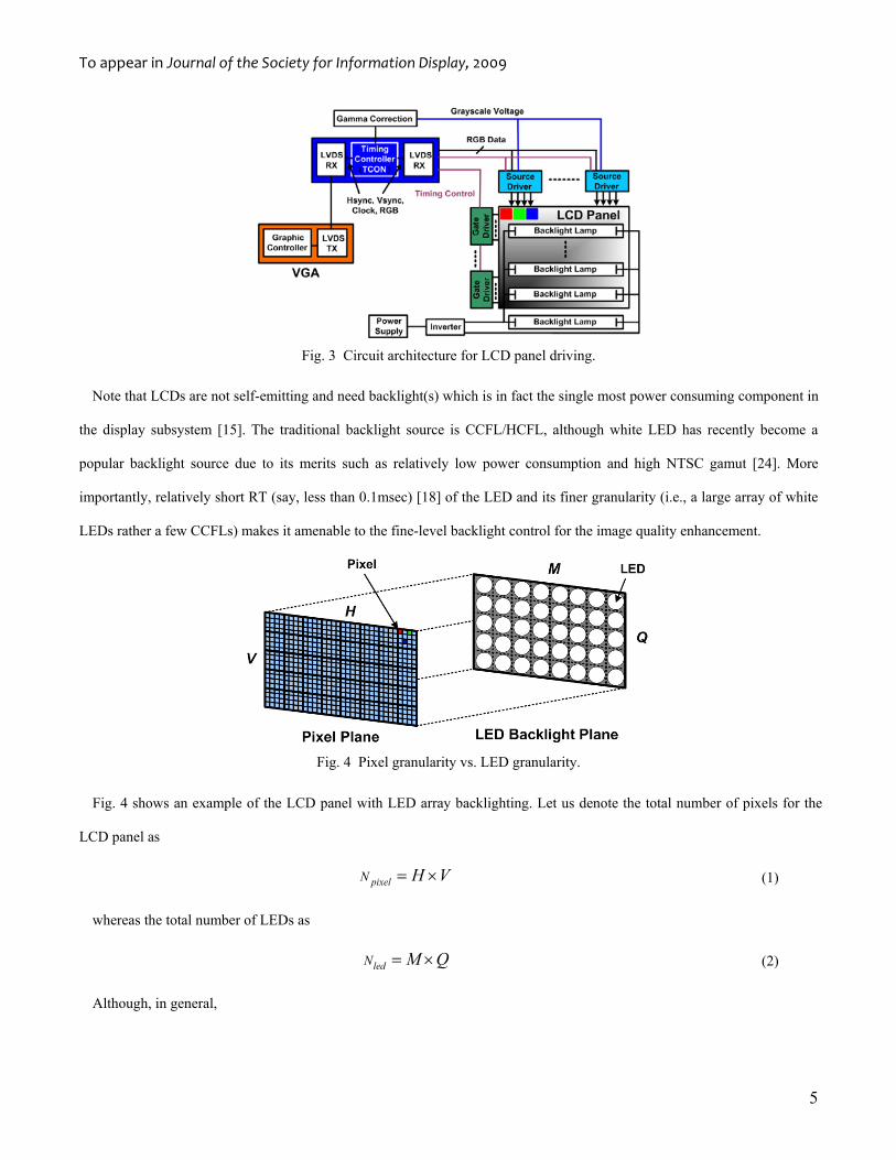
Fig. 3 shows the typical circuit architecture for an LCD panel; RGB data generated from a VGA (Video Graphics Adapter) is
sent to TCON (Timing Controller) on LCD TVs in LVDS (Low Voltage Differential Signaling) format. The TCON transmits
the RGB pixel data to the source drivers while controlling the turning-on of each pixel lines via the gate drivers. By
synchronizing the data and the timing signals, each line on the LCD panel is refreshed from the top left to the bottom right
within a given frame display deadline, which is set to the inverse of the frame rate.
To appear in Journal of the Society for Information Display, 2009
5
Fig. 3 Circuit architecture for LCD panel driving.
Note that LCDs are not self-emitting and need backlight(s) which is in fact the single most power consuming component in
the display subsystem [15]. The traditional backlight source is CCFL/HCFL, although white LED has recently become a
popular backlight source due to its merits such as relatively low power consumption and high NTSC gamut [24]. More
importantly, relatively short RT (say, less than 0.1msec) [18] of the LED and its finer granularity (i.e., a large array of white
LEDs rather a few CCFLs) makes it amenable to the fine-level backlight control for the image quality enhancement.
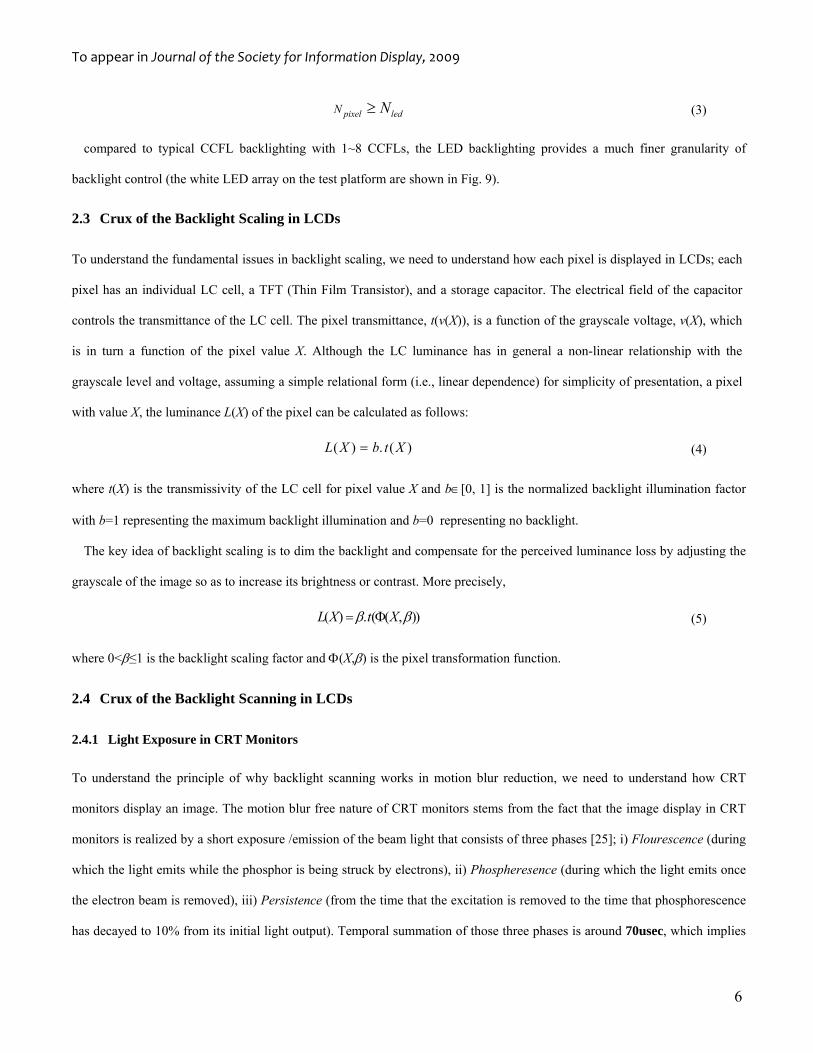
Fig. 4 Pixel granularity vs. LED granularity.
Fig. 4 shows an example of the LCD panel with LED array backlighting. Let us denote the total number of pixels for the
LCD panel as
pixelN H V= × (1)
whereas the total number of LEDs as
ledN M Q= × (2)
Although, in general,
To appear in Journal of the Society for Information Display, 2009
6
pixel ledN N≥ (3)
compared to typical CCFL backlighting with 1~8 CCFLs, the LED backlighting provides a much finer granularity of
backlight control (the white LED array on the test platform are shown in Fig. 9).
2.3 Crux of the Backlight Scaling in LCDs
To understand the fundamental issues in backlight scaling, we need to understand how each pixel is displayed in LCDs; each
pixel has an individual LC cell, a TFT (Thin Film Transistor), and a storage capacitor. The electrical field of the capacitor
controls the transmittance of the LC cell. The pixel transmittance, t(v(X)), is a function of the grayscale voltage, v(X), which
is in turn a function of the pixel value X. Although the LC luminance has in general a non-linear relationship with the
grayscale level and voltage, assuming a simple relational form (i.e., linear dependence) for simplicity of presentation, a pixel
with value X, the luminance L(X) of the pixel can be calculated as follows:
( ) . ( )L X b t X= (4)
where t(X) is the transmissivity of the LC cell for pixel value X and b∈[0, 1] is the normalized backlight illumination factor
with b=1 representing the maximum backlight illumination and b=0 representing no backlight.
The key idea of backlight scaling is to dim the backlight and compensate for the perceived luminance loss by adjusting the
grayscale of the image so as to increase its brightness or contrast. More precisely,
( ) . ( ( , ))L X t Xβ β= Φ (5)
where 0<β≤1 is the backlight scaling factor and Φ(X,β) is the pixel transformation function.
2.4 Crux of the Backlight Scanning in LCDs
2.4.1 Light Exposure in CRT Monitors
To understand the principle of why backlight scanning works in motion blur reduction, we need to understand how CRT
monitors display an image. The motion blur free nature of CRT monitors stems from the fact that the image display in CRT
monitors is realized by a short exposure /emission of the beam light that consists of three phases [25]; i) Flourescence (during
which the light emits while the phosphor is being struck by electrons), ii) Phospheresence (during which the light emits once
the electron beam is removed), iii) Persistence (from the time that the excitation is removed to the time that phosphorescence
has decayed to 10% from its initial light output). Temporal summation of those three phases is around 70usec, which implies
To appear in Journal of the Society for Information Display, 2009
7
that CRT monitors mostly display nothing but a dark screen while it briefly displays impulse-type image(s) under the refresh
rate of 60-120Hz.
2.4.2 Light-Evoked Response in HVS
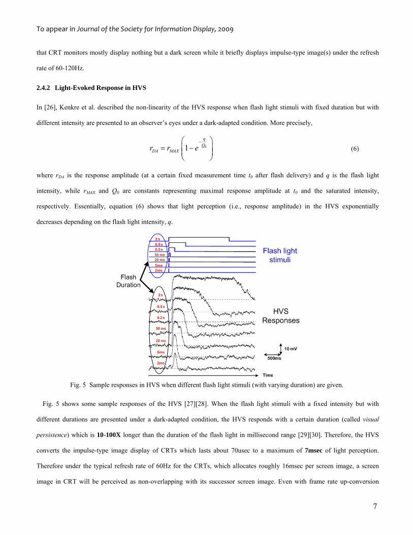
In [26], Kenkre et al. described the non-linearity of the HVS response when flash light stimuli with fixed duration but with
different intensity are presented to an observer’s eyes under a dark-adapted condition. More precisely,
01q
QDA MAXr r e
−⎛ ⎞= −⎜ ⎟⎜ ⎟
⎝ ⎠ (6)
where rDA is the response amplitude (at a certain fixed measurement time t0 after flash delivery) and q is the flash light
intensity, while rMAX and Q0 are constants representing maximal response amplitude at t0 and the saturated intensity,
respectively. Essentially, equation (6) shows that light perception (i.e., response amplitude) in the HVS exponentially
decreases depending on the flash light intensity, q.
Fig. 5 Sample responses in HVS when different flash light stimuli (with varying duration) are given.
Fig. 5 shows some sample responses of the HVS [27][28]. When the flash light stimuli with a fixed intensity but with
different durations are presented under a dark-adapted condition, the HVS responds with a certain duration (called visual
persistence) which is 10-100X longer than the duration of the flash light in millisecond range [29][30]. Therefore, the HVS
converts the impulse-type image display of CRTs which lasts about 70usec to a maximum of 7msec of light perception.
Therefore under the typical refresh rate of 60Hz for the CRTs, which allocates roughly 16msec per screen image, a screen
image in CRT will be perceived as non-overlapping with its successor screen image. Even with frame rate up-conversion
To appear in Journal of the Society for Information Display, 2009
8
[31][32], e.g., 120Hz refresh rate, this visual non-overlapping of successive frames in a CRT mostly holds. Consequently,
motion blur does not occur in CRT monitors.
All the impulse-type image display techniques for motion blur reduction (e.g., BFI, blinking/flashing, etc.) including the
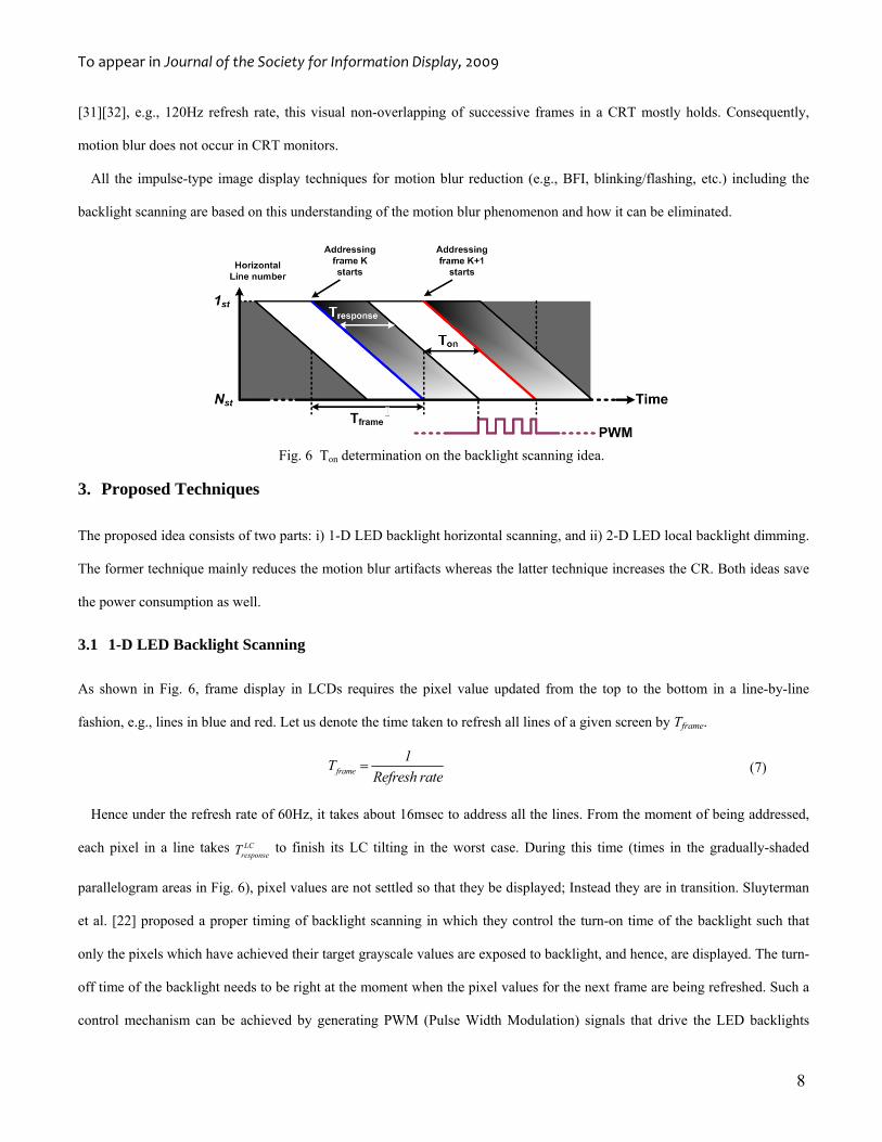
backlight scanning are based on this understanding of the motion blur phenomenon and how it can be eliminated.
Fig. 6 Ton determination on the backlight scanning idea.
3. Proposed Techniques
The proposed idea consists of two parts: i) 1-D LED backlight horizontal scanning, and ii) 2-D LED local backlight dimming.
The former technique mainly reduces the motion blur artifacts whereas the latter technique increases the CR. Both ideas save
the power consumption as well.
3.1 1-D LED Backlight Scanning
As shown in Fig. 6, frame display in LCDs requires the pixel value updated from the top to the bottom in a line-by-line
fashion, e.g., lines in blue and red. Let us denote the time taken to refresh all lines of a given screen by Tframe.
frame1T
Refresh rate= (7)
Hence under the refresh rate of 60Hz, it takes about 16msec to address all the lines. From the moment of being addressed,
each pixel in a line takes LCresponseT to finish its LC tilting in the worst case. During this time (times in the gradually-shaded
parallelogram areas in Fig. 6), pixel values are not settled so that they be displayed; Instead they are in transition. Sluyterman
et al. [22] proposed a proper timing of backlight scanning in which they control the turn-on time of the backlight such that
only the pixels which have achieved their target grayscale values are exposed to backlight, and hence, are displayed. The turn-
off time of the backlight needs to be right at the moment when the pixel values for the next frame are being refreshed. Such a
control mechanism can be achieved by generating PWM (Pulse Width Modulation) signals that drive the LED backlights
To appear in Journal of the Society for Information Display, 2009
9
(shown in the bottom of Fig. 6). Mathematically, the ON period of LEDs for the addressed pixels within a frame period
(denoted by Ton) should satisfy the following equation:
( )LCon frame responseT T T≤ − (8)
Notice that for the LCDs without backlight scanning use a Ton which is equal to Tframe.
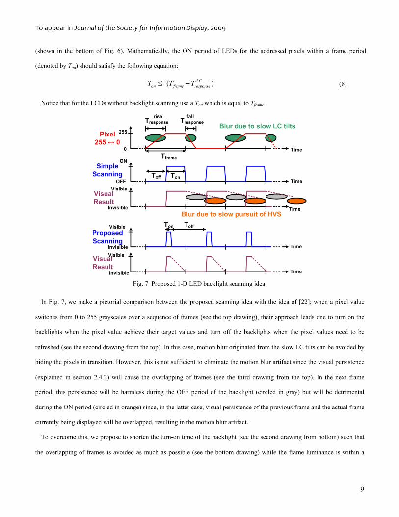
Fig. 7 Proposed 1-D LED backlight scanning idea.
In Fig. 7, we make a pictorial comparison between the proposed scanning idea with the idea of [22]; when a pixel value
switches from 0 to 255 grayscales over a sequence of frames (see the top drawing), their approach leads one to turn on the
backlights when the pixel value achieve their target values and turn off the backlights when the pixel values need to be
refreshed (see the second drawing from the top). In this case, motion blur originated from the slow LC tilts can be avoided by
hiding the pixels in transition. However, this is not sufficient to eliminate the motion blur artifact since the visual persistence
(explained in section 2.4.2) will cause the overlapping of frames (see the third drawing from the top). In the next frame
period, this persistence will be harmless during the OFF period of the backlight (circled in gray) but will be detrimental
during the ON period (circled in orange) since, in the latter case, visual persistence of the previous frame and the actual frame
currently being displayed will be overlapped, resulting in the motion blur artifact.
To overcome this, we propose to shorten the turn-on time of the backlight (see the second drawing from bottom) such that
the overlapping of frames is avoided as much as possible (see the bottom drawing) while the frame luminance is within a
To appear in Journal of the Society for Information Display, 2009
10
certain tolerance.
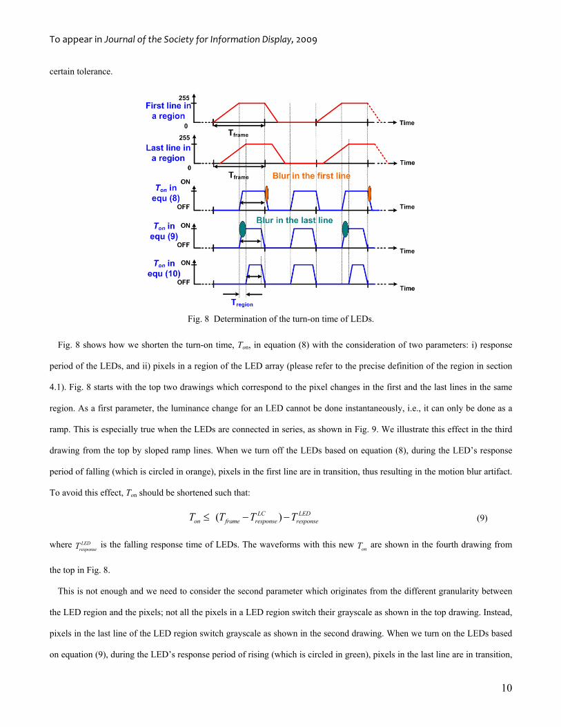
Fig. 8 Determination of the turn-on time of LEDs.
Fig. 8 shows how we shorten the turn-on time, Ton, in equation (8) with the consideration of two parameters: i) response
period of the LEDs, and ii) pixels in a region of the LED array (please refer to the precise definition of the region in section
4.1). Fig. 8 starts with the top two drawings which correspond to the pixel changes in the first and the last lines in the same
region. As a first parameter, the luminance change for an LED cannot be done instantaneously, i.e., it can only be done as a
ramp. This is especially true when the LEDs are connected in series, as shown in Fig. 9. We illustrate this effect in the third
drawing from the top by sloped ramp lines. When we turn off the LEDs based on equation (8), during the LED’s response
period of falling (which is circled in orange), pixels in the first line are in transition, thus resulting in the motion blur artifact.
To avoid this effect, Ton should be shortened such that:
( )LC LEDon frame response responseT T T T≤ − − (9)
where LEDresponseT is the falling response time of LEDs. The waveforms with this new onT are shown in the fourth drawing from
the top in Fig. 8.
This is not enough and we need to consider the second parameter which originates from the different granularity between
the LED region and the pixels; not all the pixels in a LED region switch their grayscale as shown in the top drawing. Instead,
pixels in the last line of the LED region switch grayscale as shown in the second drawing. When we turn on the LEDs based
on equation (9), during the LED’s response period of rising (which is circled in green), pixels in the last line are in transition,
To appear in Journal of the Society for Information Display, 2009
11
thereby resulting in the motion blur artifact. To avoid this effect, onT should be shortened such that:
( )LC LEDon frame response response regionT T T T T≤ − − − (10)
where Tregion is the time gap between the first and the last line updates in the LED region. We show the waveforms with this
new onT in the bottom drawing in Fig. 8.
3.2 2-D LED Local Backlight Dimming
The local backlight dimming techniques with the aid of the 2-D white LED array in the test platform uses the luminance (Y)
values of the pixels. Indeed we only have access to the 24-bit RGB signals (which exist in LVDS and FPGA) for each pixel.
To mitigate the computational complexity, we must avoid converting the RGB values to the YUV values (which is a straight-
forward task, but is expensive to do in hardware.). Instead, for all the pixels belonging to a region of the LED array (cf.
definition of the region in section 4.1), we estimate the average grayscale value (denoted by Gavg) by taking the MAX(R, G,
B) for each pixel in the region, summing all these, and dividing the sum by the total number of pixels in the region. Next, this
Gavg is used to set the LED’s luminance (denoted by β) of the region using a simple linear function of,
( ) where ( ) avgavg avg
Gf G f G
255β = = (11)
Given the value of Gavg, equation (11) calculates the corresponding backlight level, β, where 0≤β≤1. This β linearly maps
to the PWM duty ratio of 0~100%. Note that in equation (11), β is a continuous function. However, it is not feasible to
implement a continuous function in digital systems, therefore, in our experiment β is discretized into 11 different levels with a
discretized luminance of,
avgdiscrete
G10
255β
⎢ ⎥= ×⎢ ⎥⎣ ⎦
(12)
As a result of this local dimming, we maintain the highest perceived luminance (when Gavg=255) for the brightest areas of
the image since the backlight level is set to be the highest (100% PWM duty cycle). In contrast, we decrease the lowest
perceived luminance (when Gavg=0) for the dark areas since the backlight is turned off (0% PWM duty cycle), achieving the
static CR increase.
3.2.1 Why We Avoid Pixel Transformations
Most backlight scaling techniques [12]-[14] attempt to compensate for the perceived luminance loss by applying a pixel
To appear in Journal of the Society for Information Display, 2009
12
transformation technique. When a single pixel transformation is applied to a still image, the result is quite good.
Unfortunately, when pixel transformation technique is applied to a sequence of images, i.e., video, an undesirable flickering
effect is often created [15] since each image may use a different pixel transformation function, resulting in potentially
dramatic changes in values that a pixel assumes from one frame to next. In addition to applying a pixel transformation
technique to the LED array backlighting technology, one must perform histogram analysis and determine the pixel
transformation function for each ledN M Q= × region in the target frame, and subsequently, apply the pixel transformation to
all pixels of this region while adjusting the LED backlight for that region. Such computations will slow down the display
process (by as much as 10~15%, as reported in [15]), resulting in the degradation of the actual refresh rate.
Pixel transformation requires extra hardware resources (e.g., daughter board, memory, FPGA) to save the aforesaid
histograms, result of the pixel transformation, etc. for each of the LED regions for every frame. Such overhead is costly.
Additional signal processing techniques (e.g., low pass filters (LPFs) in [15]) are needed to suppress both the color break-up
over the LED regions (i.e., spatially) and the video flickering (i.e., temporally). However, spatial (temporal) LPFs tend to
lower the static (dynamic) CR, which is again undesirable.
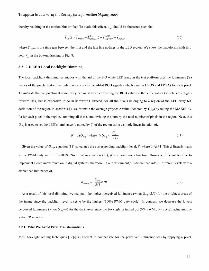
Our proposed local dimming approach avoids all these complications due to its simple nature and cost efficient realization.
Fig. 9 LED arrangement in LCD Panel.
4. Implementation and Experimental results
4.1 Methodology
For the test platform, we used a 40-inch Samsung LCD TV (Model LN-T4081F) which is capable of rendering images in full
HD (i.e., 1080p) and has up to 120Hz of refresh rate. Like the other LCD TVs, this TVs requires a high brightness hence it
To appear in Journal of the Society for Information Display, 2009
13
uses direct-light LCD panel (cf. Fig. 9). It also provides user-settable backlight levels from 0 to 10. For the experiment, we
disabled all built-in features of this TV, implement the ideas, and measured the performance. From here onwards, we denote
the proposed local dimming as ‘LD’, proposed backlight scanning as ‘PBS’ and the original image as ‘Original’.
Fig. 9 shows the LED backlight arrangement in the platform; it has a total of 768 White LEDs and those LEDs are divided
by 8 segments (2X4). Each segment has 8 regions (4X2) and every region has a string of 12 LEDs (4X3). The luminance of
those LEDs in a string is controlled as a whole where Vdd of 120V is applied to the LED shown in blue while variable voltage
of 80-90V is applied to the LED shown in red. As a result, peak-to-peak voltage of PWM signal is 40V and Supertex HV9980
chips [33] are the major component used for the PWM signal control.
The proposed two algorithms are implemented in Xilinx FPGA (Spartan 3E) and HW was properly modified such that new
PWM signals, generated based on the two ideas proposed earlier, control the luminance of LEDs. We also used the Klein K-
10 colorimeter [34] and Extech Power analyzer [35] (Model # 380803) to measure the color parameters and the power
consumption, respectively.
4.2 Experimental Results
Motion blur artifact caused by the slow LC tilts can be easily captured with general image recording devices. However, the
artifact caused by the visual persistence (cf. Fig. 7) is hard to be captured and reported in the space of a paper. As a
consequence, we omit the typical image-by-image comparison for the performance of ‘PBS’ but briefly estimate the efficacy
of the idea instead; In our experiment, the LCD TV has a refresh rate of 60Hz and its LC response time is 8msec. Based on
equation (8) the corresponding Ton for the scheme proposed in [22] is 8ms. Corresponding to this Ton, together with the
aforementioned 10-100X of visual persistence, an image frame in video lasts at least 80msec to HVS, which easily incurs
large amount of image overlap across frames (cf. Fig. 7) to HVS. In contrast, based on equation (10) the corresponding Ton for
‘PBS’ is 2ms. Hence with ‘PBS’, an image frame in video lasts about 20msec to HVS, in which the image overlap is largely
suppressed, therefore the large amount of blur artifact disappears.
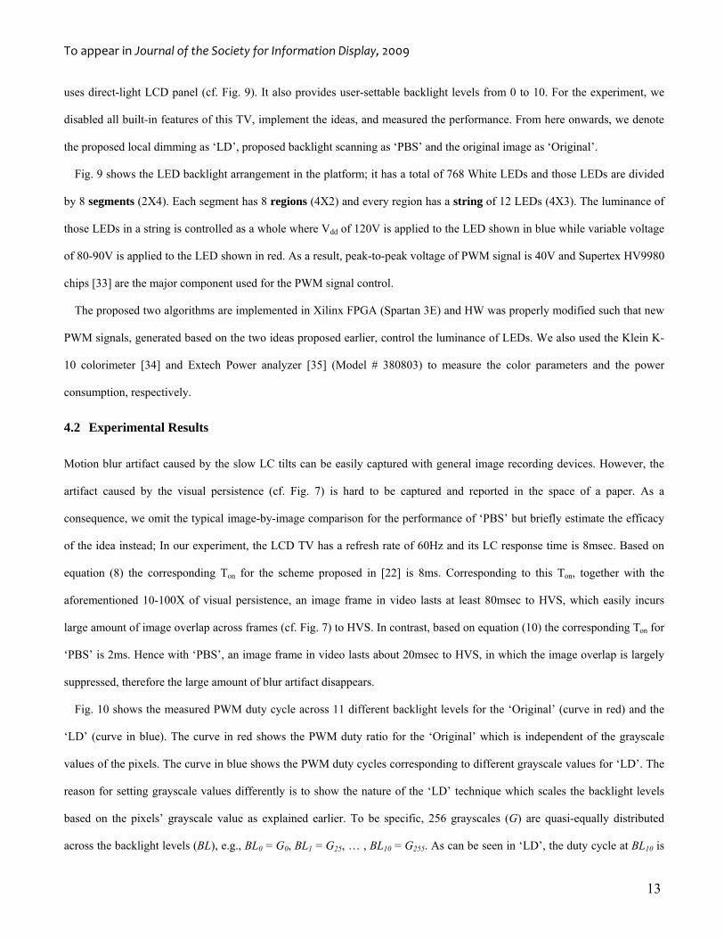
Fig. 10 shows the measured PWM duty cycle across 11 different backlight levels for the ‘Original’ (curve in red) and the
‘LD’ (curve in blue). The curve in red shows the PWM duty ratio for the ‘Original’ which is independent of the grayscale
values of the pixels. The curve in blue shows the PWM duty cycles corresponding to different grayscale values for ‘LD’. The
reason for setting grayscale values differently is to show the nature of the ‘LD’ technique which scales the backlight levels
based on the pixels’ grayscale value as explained earlier. To be specific, 256 grayscales (G) are quasi-equally distributed
across the backlight levels (BL), e.g., BL0 = G0, BL1 = G25, … , BL10 = G255. As can be seen in ‘LD’, the duty cycle at BL10 is
To appear in Journal of the Society for Information Display, 2009
14
100% while it is aggressively decreased as BL goes down, eventually reaching 0%.
Fig. 10 PWM duty cycle changes for different backlight levels in the ‘Original’ vs. ‘LD’.
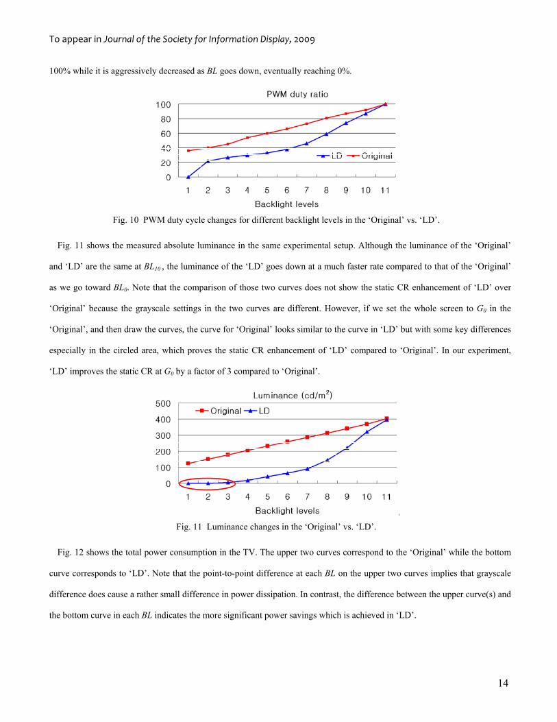
Fig. 11 shows the measured absolute luminance in the same experimental setup. Although the luminance of the ‘Original’
and ‘LD’ are the same at BL10 , the luminance of the ‘LD’ goes down at a much faster rate compared to that of the ‘Original’
as we go toward BL0. Note that the comparison of those two curves does not show the static CR enhancement of ‘LD’ over
‘Original’ because the grayscale settings in the two curves are different. However, if we set the whole screen to G0 in the
‘Original’, and then draw the curves, the curve for ‘Original’ looks similar to the curve in ‘LD’ but with some key differences
especially in the circled area, which proves the static CR enhancement of ‘LD’ compared to ‘Original’. In our experiment,
‘LD’ improves the static CR at G0 by a factor of 3 compared to ‘Original’.
Fig. 11 Luminance changes in the ‘Original’ vs. ‘LD’.
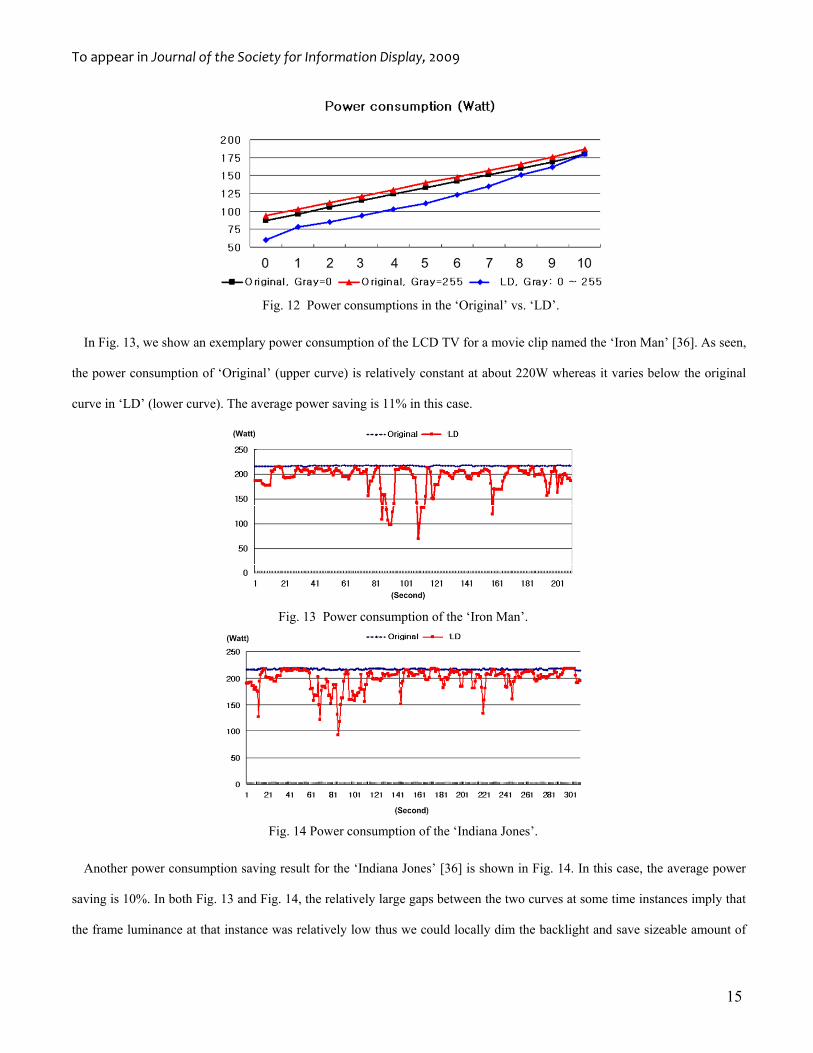
Fig. 12 shows the total power consumption in the TV. The upper two curves correspond to the ‘Original’ while the bottom
curve corresponds to ‘LD’. Note that the point-to-point difference at each BL on the upper two curves implies that grayscale
difference does cause a rather small difference in power dissipation. In contrast, the difference between the upper curve(s) and
the bottom curve in each BL indicates the more significant power savings which is achieved in ‘LD’.
To appear in Journal of the Society for Information Display, 2009
15
Fig. 12 Power consumptions in the ‘Original’ vs. ‘LD’.
In Fig. 13, we show an exemplary power consumption of the LCD TV for a movie clip named the ‘Iron Man’ [36]. As seen,
the power consumption of ‘Original’ (upper curve) is relatively constant at about 220W whereas it varies below the original
curve in ‘LD’ (lower curve). The average power saving is 11% in this case.
Fig. 13 Power consumption of the ‘Iron Man’.
Fig. 14 Power consumption of the ‘Indiana Jones’.
Another power consumption saving result for the ‘Indiana Jones’ [36] is shown in Fig. 14. In this case, the average power
saving is 10%. In both Fig. 13 and Fig. 14, the relatively large gaps between the two curves at some time instances imply that
the frame luminance at that instance was relatively low thus we could locally dim the backlight and save sizeable amount of
To appear in Journal of the Society for Information Display, 2009
16
power.
5. Conclusion
For large LCD TVs, a 1-D LED backlight scanning and a 2-D local dimming technique are proposed. Proposed techniques not
only reduce the motion blur artifacts by means of impulse representation of images in video but also increase the static
contrast ratio by means of local dimming in the image(s). We investigated the motion blur problem, starting from a
quantitative study of the display features of CRTs (which are known to be blur-free) and a physiological analysis of the
response of the human visual system. To our best knowledge, none of the previous B/L scanning works solve the motion blur
problem in this way. Moreover, consideration of the LED response (TLEDresponse which is roughly 250~400usec from our
measurement) and the LED granularity (Tregion) for the determination of more precise scan-timing are distinct features of our
work. As for the B/L local dimming, we presented a dimming solution that is simple and robust, and can be efficiently
realized in hardware. Low design complexity and software overhead is thus a unique feature of our work. The proposed local
dimming technique enhanced the static CR around 3X and saved the power consumption by average 10% in some movie clips.
References
[1] W. Song, et al., “Motion-blur Characterization on Liquid-Crystal Displays,” Journal of the SID, Vol. 16, No. 5. pp. 585-
658, 2008.
[2] X. Feng et al., “Comparisons of Motion-blur Assessment Strategies for newly emergent LCD and Backlight Driving
Technologies,” Journal of the SID, Vol. 16, No. 10. pp. 977-1079, 2008.
[3] Xiao. Feng et al., “Dynamic Gamma: Application to LCD Motion Blur Reduction,” Journal of the SID, Vol. 14, No. 10.
pp. 949-956, 2006.
[4] A. A. S. Sluyterman, “What is needed in LCD Panels to Achieve CRT-like Motion Portrayal?” Journal of the SID, Vol.
14, No. 8. pp. 681-686, 2006.
[5] B-W. Lee et al., “Reducing Gray-Level Response to One Frame: Dynamic Capacitance Compensation,” SID Int’l
Symposium Digest, 2001.
[6] S-W. Lee et al., “Motion Artifact Elimination Technology for Liquid Crystal Display Monitors: Advanced Dynamic
Capacitance Compensation Method,” Journal of the SID, Vol. 14, No. 4. pp. 387-394, 2006.
[7] T-S. Kim et al., “Response Time Compensation for Black Frame Insertion,” SID Int’l Symposium Digest, 2006.
To appear in Journal of the Society for Information Display, 2009
17
[8] T-S. Kim et al., “Analysis of Response Time Compensation for Black Frame Insertion,” Journal of the SID, Vol. 15, No.
9. pp. 741-747, 2007.
[9] J-I. Hirakata et al., “Super-TFT LCD for Moving Picture Images with the Blink Backlight System,” SID Int’l Symposium
Digest, 2001.
[10] K. Nishiyama et al., “32” WXGA LCD TV Using OCB Mode, Low Temperature p-Si TFT and Blinking Backlight
Technology” SID Int’l Symposium Digest, 2005.
[11] L. Kerofsky et al., “Brightness Preservation for LCD Backlight Dimming,” Journal of the SID, Vol. 16, No. 12. pp.
1111-1118, 2006.
[12] N. Chang et al., “DLS: Dynamic Backlight Luminance Scaling of Liquid Crystal Display,” IEEE Trans. on Very Large
Scale Integration Systems, Vol. 12, No. 8, pp. 837-846, 2004.
[13] W-C. Cheng et al., “Power Minimization in a Backlit TFT-LCD by Concurrent Brightness and Contrast Scaling,” IEEE
Trans. on Consumer Electronics, Vol. 50, No. 1, pp. 25-32, 2004.
[14] A. Iranli et al., “HEBS: Histogram Equalization for Backlight Scaling,” Design Automation and Test in Europe, Mar.
2005.
[15] A. Iranli et al., “HVS-Aware Dynamic Backlight Scaling in TFT-LCDs,” IEEE Trans. on Very Large-Scale Integration
Systems, Vol. 14, No. 10, pp. 1103-1110, 2006.
[16] E-Y. Oh et al., “IPS-Mode Dynamic LCD-TV Realization with Low Black Luminance and High Contrast by Adaptive
Dynamic Image Control Technology,” Journal of SID, Vol. 13, No. 3, pp. 215-219, 2005.
[17] P. D. Greef et al., “Adaptive Dimming and Boosting Backlight for LCD-TV Systems,” SID Int’l Symposium Digest,
2007.
[18] H. Chen et al., “Locally Pixel-Compensated Backlight Dimming for Improving Static Contrast on LED Backlit LCDs,”
SID Int’l Symposium Digest, 2007.
[19] H. Chen et al., “Locally Pixel-Compensated Backlight Dimming on LED-backlit LCD TV,” Journal of the SID, Vol. 15,
No. 12. pp. 979-1160, 2007.
[20] N. Fisekovic et al., “Scanning Backlight Parameters for Achieving the Best Picture Quality in AM LCD,” Euro Display,
2002.
[21] H-C. Hung et al., “Improvement in Moving Picture Quality by Scanning Backlight System,” Int’l Display Manufacturing
Conference, 2005
To appear in Journal of the Society for Information Display, 2009
18
[22] A. A. S. Sluyterman et al., “Architectural Choices in the Aptura Scanning Backlight for Large LCD TVs,” Journal of the
SID, Vol. 14, No. 2. pp. 169-174, 2006.
[23] P. D. Greef et al., “Adaptive Scanning, 1-D Dimming, and Boosting Backlight for LCD-TV Systems,” Journal of SID,
Vol. 14, No. 12, pp. 1103-1110, 2006.
[24] C. T. Liu et al., “Color and Image Enhancement for Large-Size TFT-LCD TVs,” SID Int’l Symposium Digest, 2005.
[25] James D. Foley, “Computer Graphics: Principles and Practices,” Addison-Wesley, 1995.
[26] J. S. Kenkre et al., “Extremely Rapid Recovery of Human Cone Circulating Current at the Extinction of Bleaching
Exposures,” Journal of Physiology, 567.1. pp. 95-112, 2005.
[27] O. A. R. Mahroo et al., “Recovery of the Human Photopic Electroretinogram after Bleaching Exposures: Estimation of
Pigment Regeneration Kinetics,” Journal of Physiology, pp. 417-437, 2003.
[28] J. Verweij et al., “Sensitivity and Dynamic of rod Signals in H1 Horizontal Cells of the Macaque Monkey Retina,”
Vision Research, Vol. 39, pp. 3662-3672, 1999.
[29] C. Friedburg et al., “Time Course of the Flash Response of Dark- and Light- Adapted Human Rod Photoreceptors
Derived from the Electroretinogram,” Journal of Physiology, Vol. 534, No. 1, pp. 217-242, 2001.
[30] T. Euler et al., “Light-Evoked Responses of Bipolar Cells in a Mammalian Retina,” Journal of Neurophysiology, Vol. 83,
pp. 1817-1829, 2000.
[31] E. B. Bellers et al., “Motion Compensated Frame Rate Conversion for Motion Blur Reduction,” SID Int’l Symposium
Digest, 2007.
[32] S-S. Kim et al., “Novel 120-Hz TFT-LCD Motion-blur Reduction Technology with Integrated Motion-Compensated
Frame-Interpolation Timing Controller,” Journal of the SID, Vol. 16, No. 3. pp. 401-515, 2008.
[33] http://www.supertex.com
[34] http://www.kleininstruments.com/k_10.html
[35] http://www.extech.com/
[36] http://www.comingsoon.net/trailers/
![Discriminative Blur Detection Featuresleojia/projects/dblurdetect/... · cal blur features for blur confidenceand type classification. Chakrabarti et al. [3] analyzed directional](https://img.pdfslide.net/doc/110x75/606a380b892efc4f822ed5db/discriminative-blur-detection-leojiaprojectsdblurdetect-cal-blur-features.jpg)