Embed Size (px)
Citation preview
Lawrence Berkeley Laboratories: Microstructured Materials Group
Page 1 of 41
Silica Aerogels Table of Contents
1. A Brief History of Silica Aerogels By Arlon Hunt and Michael
2. How Silica Aerogels are Made A description of the chemical and physical processes used to make silica aerogels. Sample recipes included.
3. How Do You Work With Aerogels Without Breaking Them? Handle with care.
4. What if you want them to break? - Silica aerogels will gently absorb the kinetic energy of impacts.
5. The Surface Chemistry of Silica Aerogels A feature of silica aerogels that can have a dramatic effect on their physical behavior.
6. The Pore Structure of Silica Aerogels The pore network of an aerogel constitutes over 95% of its volume.
7. Physical Properties of Silica Aerogels A table of measurements from various sources.
8. Optical Properties and Spectrum Silica aerogels are transparent
9. Thermal Properties The phenomenon most studied for aerogels.
10. Aerogel Nanocomposites Many compositions are possible.
11. An Optical Oxygen Sensor A special silica aerogel is at the heart of this device.

Lawrence Berkeley Laboratories: Microstructured Materials Group
Page 2 of 41
12. Technology-Transfer Opportunities/Commercial Availability of Aerogels
13. A Partial Bibliography for Silica Aerogels References to technical papers concerning silica aerogels.
Lawrence Berkeley Laboratories: Microstructured Materials Group
Page 3 of 41
A Brief History of Silica Aerogels By Arlon Hunt and Michael Ayers
Many people assume that aerogels are recent products of modern technology. In reality, the first aerogels were prepared in 1931. At that time, Steven. S. Kistler of the College of the Pacific in Stockton, California set out to prove that a "gel" contained a continuous solid network of the same size and shape as the wet gel. The obvious way to prove this hypothesis was to remove the liquid from the wet gel without damaging the solid component. As is often the case, the obvious route included many obstacles. If a wet gel were simply allowed to dry on it own, the gel would shrink, often to a fraction of its original size. This shrinkage was often accompanied by severe cracking of the gel. Kistler surmised, correctly, that the solid component of the gel was microporous, and that the liquid-vapor interface of the evaporating liquid exerted strong surface tension forces that collapsed the pore structure. Kistler then discovered the key aspect of aerogel production:
"Obviously, if one wishes to produce an aerogel [Kistler is credited with coining the term "aerogel"], he must replace the liquid with air by some means in which the surface of the liquid is never permitted to recede within the gel. If a liquid is held under pressure always greater than the vapor pressure, and the temperature is raised, it will be transformed at the critical temperature into a gas without two phases having been present at any time." (S. S. Kistler, J. Phys. Chem. 34, 52, 1932).
The first gels studied by Kistler were silica gels prepared by the acidic condensation of aqueous sodium silicate. However, attempts to prepare aerogels by converting the water in these gels to a supercritical fluid failed. Instead of leaving a silica aerogel behind, the supercritical water redissolved the silica, which then precipitated as the water was vented. It was known at the time that water in aqueous gels could be exchanged with miscible organic liquids. Kistler then tried again by first thoroughly washing the silica gels with water (to remove salts from the gel), and then exchanging the water for alcohol. By converting the alcohol to a supercritical fluid and allowing it to escape, the first true aerogels were formed. Kistler's aerogels were very similar to silica aerogels prepared today. They were transparent, low density, and highly porous materials that stimulated considerable academic interest. Over the next several years, Kistler thoroughly characterized his silica aerogels, and prepared aerogels from many other materials, including alumina, tungsten oxide, ferric oxide, tin oxide, nickel tartarate, cellulose, cellulose nitrate, gelatin, agar, egg albumen, and rubber.
A few years later, Kistler left the College of the Pacific and took a position with Monsanto Corp. Shortly thereafter, Monsanto began marketing a product known simply as "aerogel". Monsanto's Aerogel was a granular silica material. Little is known about the processing conditions used to make this material, but it is assumed that its production followed Kistler's procedures. Monsanto's Aerogel was used as an additive or a thixotropic agent in cosmetics and toothpastes.
Lawrence Berkeley Laboratories: Microstructured Materials Group
Page 4 of 41
Very little new work on aerogels occurred throughout the next three decades. Eventually, in the 1960s, the development of inexpensive "fumed" silica undercut the market for aerogel, and Monsanto ceased production.
Aerogels had been largely forgotten when, in the late 1970s, the French government approached Stanislaus Teichner at Universite Claud Bernard, Lyon seeking a method for storing oxygen and rocket fuels in porous materials. There is a legend passed on between researchers in the aerogel community concerning what happened next. Teichner assigned one of his graduate students the task of preparing and studying aerogels for this application. However, using Kistler's method, which included two time-consuming and laborious solvent exchange steps, their first aerogel took weeks to prepare. Teichner then informed his student that a large number of aerogel samples would be needed for him to complete his dissertation. Realizing that this would take many, many years to accomplish, the student left Teichner's lab with a nervous breakdown. Upon returning after a brief rest, he was strongly motivated to find a better synthetic process. This directly lead to one of the major advances in aerogel science, namely the application of sol-gel chemistry to silica aerogel preparation. This process replaced the sodium silicate used by Kistler with an alkoxysilane, (tetramethyorthosilicate, TMOS). Hydrolyzing TMOS in a solution of methanol produced a gel in one step (called an "alcogel"). This eliminated two of the drawbacks in Kistler's procedure, namely, the water-to-alcohol exchange step and the presence of inorganic salts in the gel. Drying these alcogels under supercritical alcohol conditions produced high-quality silica aerogels. In subsequent years, Teichner's group, and others extended this approach to prepare aerogels of a wide variety of metal oxide aerogels.
After this discovery, new developments in aerogels science and technology occurred rapidly as an increasing number of researchers joined the field. Some of the more notable achievements are:
• In the early 1980s particle physics researchers realized that silica aerogels would be an ideal medium for the production and detection of Cherenkov radiation. These experiments required large transparent tiles of silica aerogel. Using the TMOS method, two large detectors were fabricated. One using 1700 liters of silica aerogel in the TASSO detector at the Deutsches Elektronen Synchrotron (DESY) in Hamburg, Germany, and another at CERN using 1000 liters of silica aerogel prepared at the University of Lund in Sweden.
• The first pilot plant for the production of silica aerogel monoliths using the TMOS method was established by members of the Lund group in Sjobo, Sweden. The plant included a 3000 liter autoclave designed to handle the high temperatures and pressures encountered for supercritical methanol (240 degrees C and 80 atmospheres). However, in 1984 the autoclave developed a leak during a production run. The room containing the vessel quickly filled with methanol vapors and subsequently exploded. Fortunately, there were no fatalities in this incident, but the facility was completely destroyed. The plant was later rebuilt and continues to produce silica aerogels using the TMOS process. The plant is currently operated by the Airglass Corp.
• In 1983 the Arlon Hunt and the Microstructured Materials Group at Berkeley Lab found that the very toxic compound TMOS could be replaced with tetraethylorthosilicate (TEOS), a much safer reagent. This did not lower the quality of the aerogels produced.
Lawrence Berkeley Laboratories: Microstructured Materials Group
Page 5 of 41
• At the same time the Microstructured Materials Group also found that the alcohol within a gel could be replaced by liquid carbon dioxide before supercritical drying without harming the aerogel. This represented a major advance in safety as the critical point of CO2 (31 degrees C and 1050 psi) occurs at much less severe conditions than the critical point of methanol (240 degrees C and 1600 psi). Additionally, carbon dioxide does not pose an explosion hazard as does alcohol. This process was put to use in making transparent silica aerogel tiles from TEOS.
• BASF in Germany simultaneously developed CO2 substitution methods for the preparation of silica aerogel beads from sodium silicate. This material was in production until l996 and was marketed as "BASOGEL".
• In 1985 Professor Jochen Fricke organized the first International Symposium on Aerogels in Wurzburg, Germany. Twenty-five papers were presented at this conference by researchers from around the world. Subsequent ISAs were held in 1988 (Montpellier, France), 1991 (Wurzburg), and 1994 (Berkeley, California, USA). The Fourth ISA set an attendance record with 151 participants, 10 invited papers, 51 contributed papers, and 35 poster presentations. The fifth ISA was recently held in Montpellier with almost 200 attendees.
• In the late 1980s, researchers at Lawrence Livermore National Laboratory (LLNL) lead by Larry Hrubesh prepared the worlds lowest density silica aerogel (and the lowest density solid material). This aerogel had a density of 0.003 g/cm3, only three times that of air.
• Shortly thereafter, Rick Pekala, also of LLNL, extended the techniques used to prepare inorganic aerogels to the preparation of aerogels of organic polymers. These included resorcinol-formaldehyde, melamine-formaldehyde aerogels. Resorcinol-formaldehyde aerogels could be pyrolyzed to give aerogels of pure carbon. This opened an completely new area in aerogel research.
• Thermalux, L.P. was founded in 1989 by Arlon Hunt, and others, in Richmond California. Thermalux operated a 300 liter autoclave for the production of silica aerogel monoliths from TEOS using the carbon dioxide substitution process. Thermalux prepared a large quantity of aerogels, but, unfortunately, ceased operations in 1992.
• Silica aerogel, prepared at the Jet Propulsion Laboratory, has flown on several Space Shuttle missions. On these flights very low density aerogel was used to collect and return samples of high-velocity cosmic dust.
• Researchers at the University of New Mexico, lead by C. Jeff Brinker and Doug Smith, and at other institutions have become increasingly successful at eliminating the supercritical drying step used in aerogel production by chemically modifying the surface of the gel prior to drying. This work lead to the founding of Nanopore to commercialize lower-cost aerogels.
• In 1992, Hoechst Corp. in Frankfurt, Germany aslo began a program in low cost granular aerogels.
• The Aerojet Corp. in Sacramento, California began a cooperative project with Berkeley Lab, LLNL, and others to commercialize aerogels using the carbon dioxide substitution process in 1994. Aerojet obtained the 300 liter autoclave formerly operated by Thermalux and produced various forms of silica, resorcinol-formaldehyde, and carbon aerogels. However, this program was abandoned in 1996.
Lawrence Berkeley Laboratories: Microstructured Materials Group
Page 6 of 41
With research and development proceeding at an ever increasing rate, it is likely that many more advances in aerogel technology and applications are imminent.
How Silica Aerogels Are Made
The discussion below relies upon the following terms:
Hydrolysis: The reaction of a metal alkoxide (M-OR) with water, forming a metal hydroxide (M-OH).
Condensation: A condensation reaction occurs when two metal hydroxides (M-OH + HO-M) combine to give a metal oxide species (M-O-M). The reaction forms one water molecule.
Sol: A solution of various reactants that are undergoing hydrolysis and condensation reactions. The molecular weight of the oxide species produced continuously increases. As these species grow, they may begin to link together in a three-dimensional network.
Gel Point: The point in time at which the network of linked oxide particles spans the container holding the Sol. At the gel point the Sol becomes an Alcogel.
Alcogel (wet gel): At the gel point, the mixture forms a rigid substance called an alcogel. The alcogel can be removed from its original container and can stand on its own. An alcogel consists of two parts, a solid part and a liquid part. The solid part is formed by the three-dimensional network of linked oxide particles. The liquid part (the original solvent of the Sol) fills the free space surrounding the solid part. The liquid and solid parts of an alcogel occupy the same apparent volume.
Supercritical fluid: A substance that is above its critical pressure and critical temperature. A supercritical fluid possesses some properties in common with a liquids (density, thermal conductivity) and some in common with gases. (fills its container, does not have surface tension).
Aerogel: What remains when the liquid part of an alcogel is removed without damaging the solid part (most often achieved by supercritical extraction). If made correctly, the aerogel retains the original shape of the alcogel and at least 50% (typically >85%) of the alcogel's volume.
Xerogel: What remains when the liquid part of an alcogel is removed by evaporation, or similar methods. Xerogels may retain their original shape, but often crack. The shrinkage during drying is often extreme (~90%) for xerogels.
Lawrence Berkeley Laboratories: Microstructured Materials Group
Page 7 of 41
Sol-Gel Chemistry
The formation of aerogels, in general, involves two major steps, the formation of a wet gel, and the drying of the wet gel to form an aerogel. Originally, wet gels were made by the aqueous condensation of sodium silicate, or a similar material. While this process worked well, the reaction formed salts within the gel that needed to be removed by many repetitive washings (a long, laborious procedure). With the rapid development of sol-gel chemistry over the last few decades, the vast majority of silica aerogels prepared today utilize silicon alkoxide precursors. The most common of these are tetramethyl orthosilicate (TMOS, Si(OCH3)4), and tetraethyl orthosilicate (TEOS, Si(OCH2CH3)4). However, many other alkoxides, containing various organic functional groups, can be used to impart different properties to the gel. Alkoxide-based sol-gel chemistry avoids the formation of undesirable salt by-products, and allows a much greater degree of control over the final product. The balanced chemical equation for the formation of a silica gel from TEOS is:
Si(OCH2CH3)4 (liq.) + 2H2O (liq.) = SiO2 (solid) + 4HOCH2CH3 (liq.)
The above reaction is typically performed in ethanol, with the final density of the aerogel dependent on the concentration of silicon alkoxide monomers in the solution. Note that the stoichiometry of the reaction requires two moles of water per mole of TEOS. In practice, this amount of water leads to incomplete reaction, and weak, cloudy aerogels. Most aerogel recipes, therefore, use a higher water ratio than is required by the balanced equation (anywhere from 4-30 equivalents).
Catalysts
The kinetics of the above reaction are impractically slow at room temperature, often requiring several days to reach completion. For this reason, acid or base catalysts are added to the formulation. The amount and type of catalyst used play key roles in the microstructural, physical and optical properties of the final aerogel product.
Acid catalysts can be any protic acid, such as HCl. Basic catalysis usually uses ammonia, or ammonia buffered with ammonium fluoride. Aerogels prepared with acid catalysts often show more shrinkage during supercritical drying and may be less transparent than base catalyzed aerogels. The microstructural effects of various catalysts are harder to describe accurately, as the substructure of the primary particles of aerogels can be difficult to image with electron microscopy. All show small (2-5 nm diameter) particles that are generally spherical or egg-shaped. With acid catalysis, however, these particles may appear "less solid" (looking something like a ball of string) than those in base-catalyzed gels.
As condensation reactions progress the sol will set into a rigid gel. At this point, the gel is usually removed from its mold. However, the gel must be kept covered by alcohol to prevent evaporation of the liquid contained in the pores of the gel. Evaporation causes severe damage to the gel and will lead to poor quality aerogels
Lawrence Berkeley Laboratories: Microstructured Materials Group
Page 8 of 41
Single-Step vs. Two-Step Aerogels
Typical acid or base catalyzed TEOS gels are often classified as "single-step" gels, referring to the "one-pot" nature of this reaction. A more recently developed approach uses pre-polymerized TEOS as the silica source. Pre-polymerized TEOS is prepared by heating an ethanol solution of TEOS with a sub-stoichiometric amount of water and an acid catalyst. The solvent is removed by distillation, leaving a viscous fluid containing higher molecular weight silicon alkoxy-oxides. This material is redissolved in ethanol and reacted with additional water under basic conditions until gelation occurs. Gels prepared in this way are known as "two-step" acid-base catalyzed gels. Pre-polymerized TEOS is available commercially in the U.S. from Silbond Corp. (Silbond H-5).
These slightly different processing conditions impart subtle, but important changes to the final aerogel product. Single-step base catalyzed aerogels are typically mechanically stronger, but more brittle, than two-step aerogels. While two-step aerogels have a smaller and narrower pore size distribution and are often optically clearer than single-step aerogels.
Aging and Soaking
When a sol reaches the gel point, it is often assumed that the hydrolysis and condensation reactions of the silicon alkoxide reactant are complete. This is far from the case. The gel point simply represents the time when the polymerizing silica species span the container containing the sol. At this point the silica backbone of the gel contains a significant number of unreacted alkoxide groups. In fact, hydrolysis and condensation can continue for several times the time needed for gelation. Failure to realize, and to accommodate this fact is one of the most common mistakes made in preparing silica aerogels. The solution is simple, patience. Sufficient time must be given for the strengthening of the silica network. This can be enhanced by controlling the pH and water content of the covering solution. Common aging procedures for base catalyzed gels typically involve soaking the gel in an alcohol/water mixture of equal proportions to the original sol at a pH of 8-9 (ammonia). The gels are best left undisturbed in this solution for up to 48 hours.
This step, and all subsequent processing steps, are diffusion controlled. That is, transport of material into, and out of, the gel is unaffected by convection or mixing (due to the solid silica network). Diffusion, in turn, is affected by the thickness of the gel. In short, the time required for each processing step increases dramatically as the thickness of the gel increases. This limits the practical production of aerogels to 1-2 cm-thick pieces.
After aging the gel, all water still contained within its pores must be removed prior to drying. This is simply accomplished by soaking the gel in pure alcohol several times until all the water is removed. Again, the length of time required for this process is dependent on the thickness of the gel. Any water left in the gel will not be removed by supercritical drying, and will lead to an opaque, white, and very dense aerogel.
Lawrence Berkeley Laboratories: Microstructured Materials Group
Page 9 of 41
Supercritical Drying
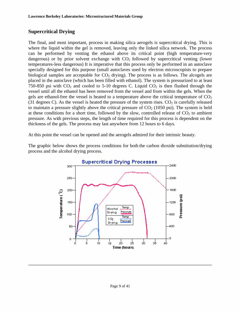
The final, and most important, process in making silica aerogels is supercritical drying. This is where the liquid within the gel is removed, leaving only the linked silica network. The process can be performed by venting the ethanol above its critical point (high temperature-very dangerous) or by prior solvent exchange with CO2 followed by supercritical venting (lower temperatures-less dangerous) It is imperative that this process only be performed in an autoclave specially designed for this purpose (small autoclaves used by electron microscopists to prepare biological samples are acceptable for CO2 drying). The process is as follows. The alcogels are placed in the autoclave (which has been filled with ethanol). The system is pressurized to at least 750-850 psi with CO2 and cooled to 5-10 degrees C. Liquid CO2 is then flushed through the vessel until all the ethanol has been removed from the vessel and from within the gels. When the gels are ethanol-free the vessel is heated to a temperature above the critical temperature of CO2 (31 degrees C). As the vessel is heated the pressure of the system rises. CO2 is carefully released to maintain a pressure slightly above the critical pressure of CO2 (1050 psi). The system is held at these conditions for a short time, followed by the slow, controlled release of CO2 to ambient pressure. As with previous steps, the length of time required for this process is dependent on the thickness of the gels. The process may last anywhere from 12 hours to 6 days.
At this point the vessel can be opened and the aerogels admired for their intrinsic beauty.
The graphic below shows the process conditions for both the carbon dioxide substitution/drying process and the alcohol drying process.
Lawrence Berkeley Laboratories: Microstructured Materials Group
Page 10 of 41
Typical Recipes
Single-Step Base Catalyzed Silica Aerogel
This will produce an aerogel with a density of approx. 0.08 g/cm3. The gel time should be 60-120 minutes, depending on temperature.
1. Mix two solutions: 1. Silica solution containing 50 mL of TEOS, 40 mL of ethanol 2. Catalyst solution containing 35 mL of ethanol, 70 mL of water, 0.275 mL of 30%
aqueous ammonia, and 1.21 mL of 0.5 M ammonium fluoride. 2. Slowly add the catalyst solution to the silica solution with stirring. 3. Pour the mixture into an appropriate mold until gelation. 4. Process as described above.
Two-Step Acid-Base Catalyzed Silica Aerogel
This will produce an aerogel with a density of approx. 0.08 g/cm3. The gel time should be 30-90 minutes, depending on temperature.
1. Mix two solutions: 1. Silica solution containing 50 mL of precondensed silica (Silbond H-5, or
equivalent), 50mL of ethanol 2. Catalyst solution containing 35 mL of ethanol, 75 mL of water, and 0.35 mL of
30% aqueous ammonia. 2. Slowly add the catalyst solution to the silica solution with stirring. 3. Pour the mixture into an appropriate mold until gelation. 4. Process as described above.
How Do You Work With Silica Aerogel Without Breaking It?
The first thing most people do when they touch silica aerogels for the first time is shatter it into a million pieces. You may hear statements in the media like-"A new Space-Age material that will support up to 1000 times its own weight..." This may be true, but it is important to remember that since silica aerogel is a very low density material, "1000 times its own weight" isn't very much weight at all. Also, remember that silica aerogel is just another form of glass. If aerogel is handled roughly, it will break just like glass. However, if care is taken, the material can be handled and shaped effectively. A few pointers:
• Don't try to pick up large pieces by the corners. Slide a thin sheet of metal, or other stiff material, under the aerogel and use this to move the piece.
Lawrence Berkeley Laboratories: Microstructured Materials Group
Page 11 of 41
• Silica aerogel is much more durable if it is under compression. This is simply accomplished by vacuum-sealing the aerogel in a plastic bag (a typical food sealer works well for this). This method is very useful for shipping samples.
• Silica aerogel is best cut using a diamond coated saw, similar to the type used by gem and stone cutters. The most difficult problem here is holding the piece steady. A vacuum chuck works well for this.
• Most silica aerogel is destroyed by contact with liquids. However, it can be protected from damage by water (see the section on surface chemistry)
• Rapid changes in ambient pressure can cause the aerogel to shatter as gases try to enter or escape the pore network. Use care when placing aerogels under high vacuum.
Many people ask if there are any hazards associated with handling silica aerogel. Working with aerogel with your bare hands can have a slight desiccating effect on the skin. This is due to the absorbance of moisture and oils from the skin into the pores of the aerogel. This is more of a nuisance than a hazard and can be avoided by wearing gloves. Cutting and shaping aerogels usually produces a cloud of fine dust. The particles of aerogel in the dust are smooth and round and, therefore, are not considered to be a laceration hazard (as asbestos is). Nevertheless, it is a good precaution to work in a fume hood or wear a good respirator to avoid inhalation of the aerogel dust.
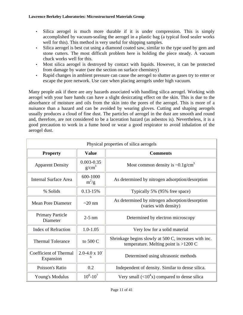
Physical properties of silica aerogels
Property Value Comments
Apparent Density 0.003-0.35 g/cm3 Most common density is ~0.1g/cm3
Internal Surface Area 600-1000 m2/g As determined by nitrogen adsorption/desorption
% Solids 0.13-15% Typically 5% (95% free space)
Mean Pore Diameter ~20 nm As determined by nitrogen adsorption/desorption (varies with density)
Primary Particle Diameter 2-5 nm Determined by electron microscopy
Index of Refraction 1.0-1.05 Very low for a solid material
Thermal Tolerance to 500 C Shrinkage begins slowly at 500 C, increases with inc. temperature. Melting point is >1200 C
Coefficient of Thermal Expansion
2.0-4.0 x 10-
6 Determined using ultrasonic methods
Poisson's Ratio 0.2 Independent of density. Similar to dense silica.
Young's Modulus 106-107 Very small (<104x) compared to dense silica
Lawrence Berkeley Laboratories: Microstructured Materials Group
Page 12 of 41
Physical properties of silica aerogels
Property Value Comments
N/m2
Tensile Strength 16 kPa For density = 0.1 g/cm3.
Fracture Toughness ~0.8 kPa*m1/2 For density = 0.1 g/cm3. Determined by 3-point bending
Dielectric Constant ~1.1 For density = 0.1 g/cm3. Very low for a solid material
Sound Velocity Through the Medium 100 m/sec For density = 0.07 g/cm3. One of the lowest velocities
for a solid material
Silica Aerogels for Absorbing Kinetic Energy
When someone who has never seen a piece of silica aerogel holds some for the first time, the following chain of events usually results. The observer first notices the transparency and light weight of the aerogel and makes some sort of remark about these properties. Then the piece is held between two fingers and gently squeezed. The aerogel gives a little, and springs back. Then a little more force is applied and...pffttt, the piece shatters into a thousand pieces, most of which find a home deep in the carpeting, never to be seen again. Not surprisingly, researchers who have spent the time and effort required to make silica aerogels are usually very reluctant to hand them out to just anyone. Because of this, an application of silica aerogels that has been largely overlooked is their use as an absorber of kinetic energy (impacts) in safety and protective devices.
Energy Absorbing Materials
In very simplified terms, materials absorb kinetic energy by plastic deformation, elastic deformation, brittle fracture, or by the fluid dynamics of gases or liquids within the material. Materials used today for absorbing impacts are commonly organic foams, such as expanded polystyrene, polyurethanes, polyethers, or polyethylene. These typically show elastomeric or plastic behavior. Silica aerogels, being an inorganic solid, are inherently brittle. A brittle material would, at first, seem to be a poor choice for a cushioning material. However, as silica aerogels are usually very low density materials, the collapse of the solid network occurs gradually, spreading the force of impact out over a longer time. Additionally, as silica aerogels are an open-pored material, the gas contained within the bulk of the solid in forced outwards as the material collapses. In doing so, the gas must pass through the pore network of the aerogel. The frictional forces caused as a gas passes through a restricted opening are indirectly proportional to the square of the pore diameter. As silica aerogels have very narrow pores (~20-50 nm), gases
Lawrence Berkeley Laboratories: Microstructured Materials Group
Page 13 of 41
rapidly passing through the material will absorb a considerable amount of energy. Therefore, the energy of an object impacting a silica aerogel is taken up by the aerogel by the collapse of its solid structure and the release of gas from within the material.
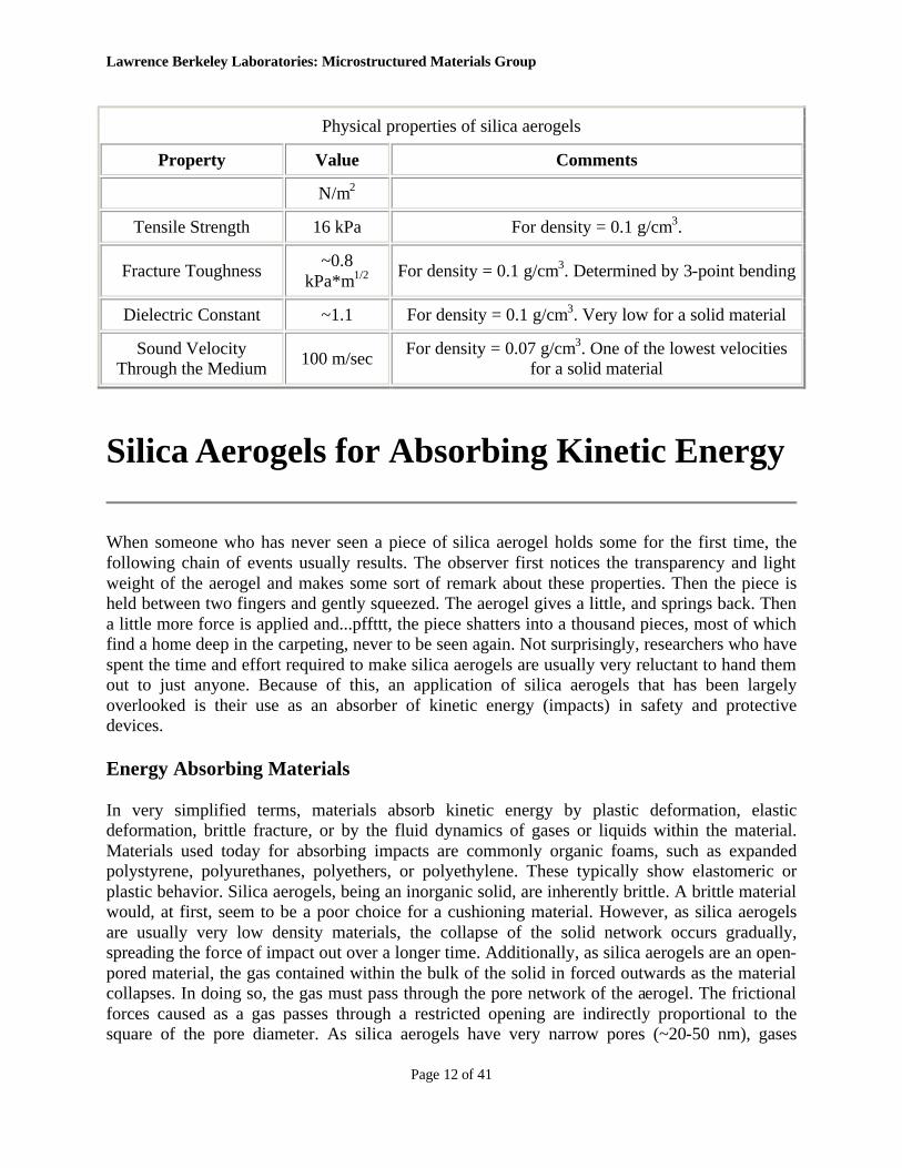
An effective material for use in safety devices will serve to minimize the force felt by the object (or person) to be protected. This is usually done by spreading the deceleration of the impacting object over a longer period of time. The graphic below shows load versus time for a silica aerogels sample, and two other materials. The samples were cubes 5 cm on a side and were crushed by an 8 lb. weight traveling at 11 ft/sec. The red curve represents a silica aerogel with a density of 0.1g/cm3, the yellow curve is expanded polystyrene, and the green is an elastomeric polypropylene foam. The plots show that both the aerogel and the polystyrene foam reduce the maximum load produced to a very low level. It may, therefore, seem that readily available polystyrene foam may be a more appropriate material than the more unusual silica aerogel.
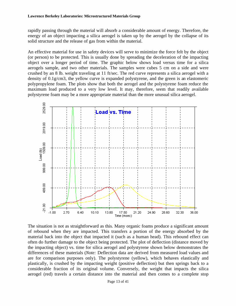
The situation is not as straightforward as this. Many organic foams produce a significant amount of rebound when they are impacted. This transfers a portion of the energy absorbed by the material back into the object that impacted it (such as a human head). This rebound effect can often do further damage to the object being protected. The plot of deflection (distance moved by the impacting object) vs. time for silica aerogel and polystyrene shown below demonstrates the differences of these materials (Note: Deflection data are derived from measured load values and are for comparison purposes only). The polystyrene (yellow), which behaves elastically and plastically, is crushed by the impacting weight (positive deflection) but then springs back to a considerable fraction of its original volume. Conversely, the weight that impacts the silica aerogel (red) travels a certain distance into the material and then comes to a complete stop

Lawrence Berkeley Laboratories: Microstructured Materials Group
Page 14 of 41
without bouncing. This is an important phenomenon to consider when developing materials for safety and protective devices.
These data were collected using a Dynatup Drop-Weight System with the kind assistance of GRC Instruments Inc, Santa Barbara, CA, a division of GRC International.
Environmental Concerns
The production and use of silica aerogels is environmentally benign. No significantly hazardous wastes are produced during their production. The disposal of silica aerogels is perfectly natural. In the environment, they quickly crush into a fine powder that is essentially identical to one of the most common substances on Earth, namely, sand. Additionally, silica aerogels are completely non-toxic and non-flammable. If they eventually find their way into widespread use as protective materials, they could eliminate a very large amount of unwanted plastic materials.
Potential Uses
The attractive energy absorbing properties of silica aerogels may lead to their use in various applications. These may include personal protection in motor vehicles, protection of sensitive equipment such as aircraft flight data recorders, and protection of electronic equipment such as laptop computer hard drives.
Lawrence Berkeley Laboratories: Microstructured Materials Group
Page 15 of 41
The Surface Chemistry of Silica Aerogels
Silica aerogels contain primary particles of 2-5 nm in diameter. Silica particles of such a small size have an extraordinarily large surface-to-volume ratio (~2 x 10⁹ m-1) and a corresponding high specific surface area (~900 m2/g). It is not surprising, therefore, that the chemistry of the interior surface of an aerogel plays a dominant role in its chemical and physical behavior. It is this property that makes aerogels attractive materials for use as catalysts, catalyst substrates, and adsorbents.
The nature of the surface groups of a silica aerogel are strongly dependent on the conditions used in its preparation. For example, if an aerogel is prepared using the supercritical alcohol drying process, its surface may consist primarily of alkoxy- (-OR) groups. On the other hand, with the carbon dioxide drying process the surface is almost exclusively covered with hydroxyl (-OH) groups. The extent of hydroxyl- coverage is ~5 -OH/nm2, a value consistent with other forms of silica. This value, combined with their high specific surface area, means that silica aerogels present an extremely large number of accessible hydroxyl groups. Silica aerogels are therefore a somewhat acidic material. A more striking effect of the hydroxyl surface is seen the physical behavior of silica aerogels.
As with most hydroxyl surfaces, the surface of silica aerogels can show strong hydrogen-bonding effects. Because of this, silica aerogels with hydroxyl surface are extremely hygroscopic. Dry silica aerogels will absorb water directly from moist air, with mass increases of up to 20%. This absorption has no visible effect on the aerogel, and is completely reversible. Simply heating the material to 100-120 degrees C will completely dry the material in about an hour (or longer, depending on thickness). As the sample cools, water will reabsorb quickly (mass increases can be seen almost immediately).
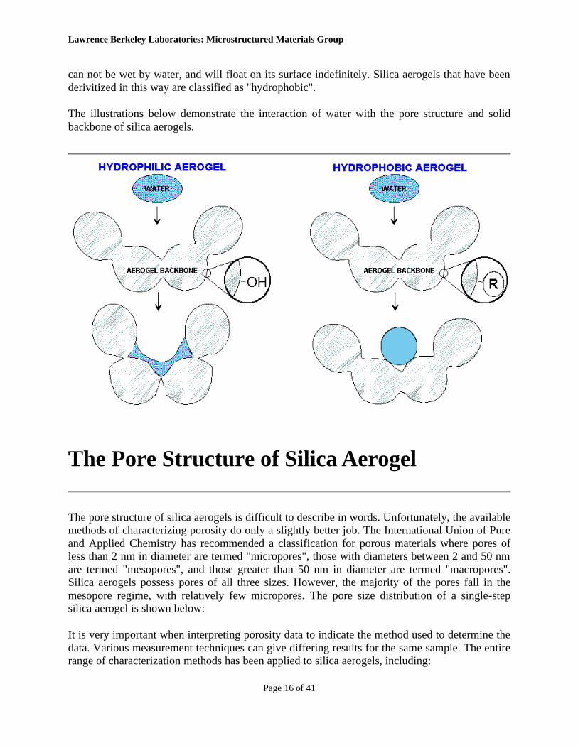
While the adsorption of water vapor does not harm silica aerogels, contact with liquid water has disastrous results. The strong attractive forces that the hydroxyl surface exerts on water vapor also attracts liquid water. However, when liquid water enters a nanometer-scale pore, the surface tension of water exerts capillary forces strong enough to fracture the solid silica backbone. The net effect is a complete collapse of the aerogel monolith. The material changes from a transparent solid with a definite shape to a fine white powder. The powder has the same mass and total surface area as the original aerogel, but has lost its solid integrity. Silica aerogels with fully hydroxylated surfaces are, therefore, classified as "hydrophilic".
This would appear to pose a significant problem to using silica aerogels in exposed environments. Fortunately, this problem can be easily circumvented by converting the surface hydroxyl (-OH) groups to a non-polar (-OR) group. This is effective when R is one of many possible aliphatic groups, although trimethylsilyl- groups are the most common. The derivitization can be performed before (on the wet gel) or after (on the aerogel) supercritical drying. This completely protects the aerogel from damage by liquid water by eliminating the attractive forces between water and the silica surface. In fact, silica aerogels treated in this way
Lawrence Berkeley Laboratories: Microstructured Materials Group
Page 16 of 41
can not be wet by water, and will float on its surface indefinitely. Silica aerogels that have been derivitized in this way are classified as "hydrophobic".
The illustrations below demonstrate the interaction of water with the pore structure and solid backbone of silica aerogels.
The Pore Structure of Silica Aerogel
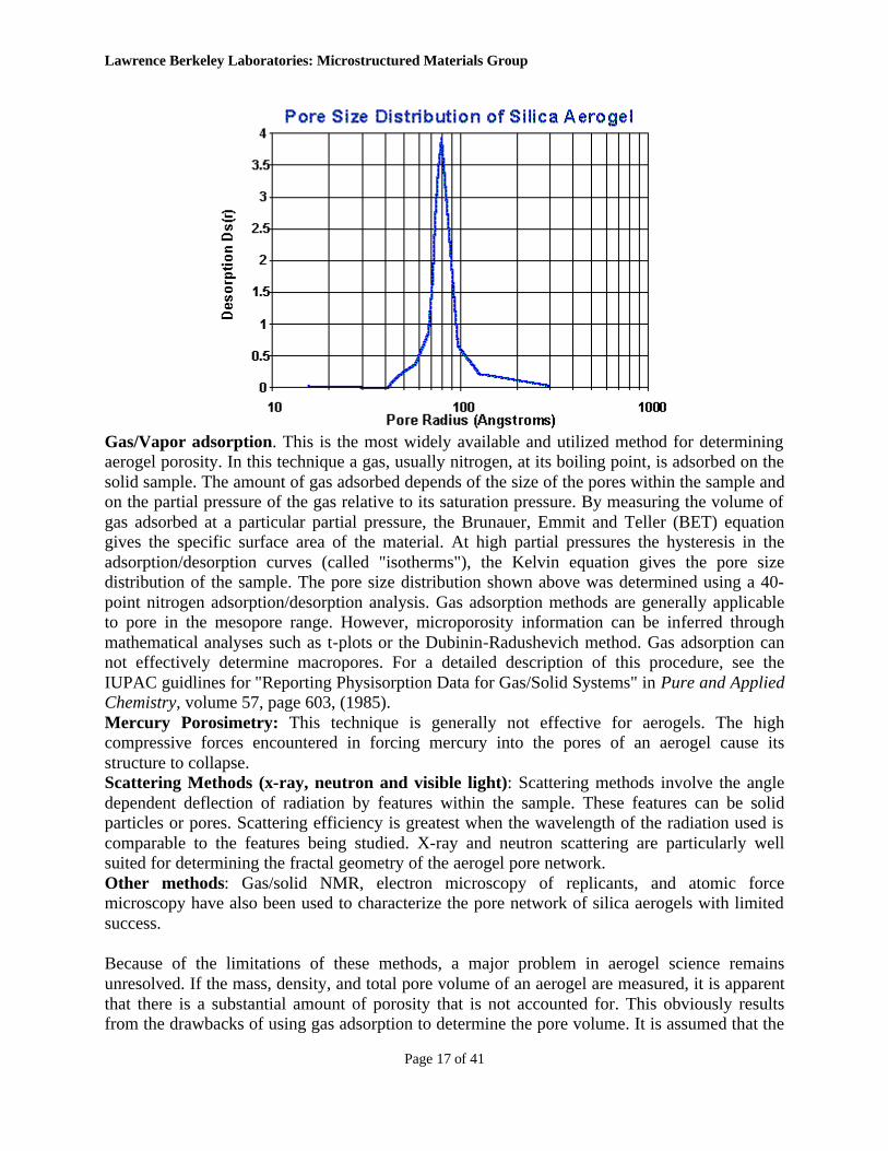
The pore structure of silica aerogels is difficult to describe in words. Unfortunately, the available methods of characterizing porosity do only a slightly better job. The International Union of Pure and Applied Chemistry has recommended a classification for porous materials where pores of less than 2 nm in diameter are termed "micropores", those with diameters between 2 and 50 nm are termed "mesopores", and those greater than 50 nm in diameter are termed "macropores". Silica aerogels possess pores of all three sizes. However, the majority of the pores fall in the mesopore regime, with relatively few micropores. The pore size distribution of a single-step silica aerogel is shown below:
It is very important when interpreting porosity data to indicate the method used to determine the data. Various measurement techniques can give differing results for the same sample. The entire range of characterization methods has been applied to silica aerogels, including:
Lawrence Berkeley Laboratories: Microstructured Materials Group
Page 17 of 41
Gas/Vapor adsorption. This is the most widely available and utilized method for determining aerogel porosity. In this technique a gas, usually nitrogen, at its boiling point, is adsorbed on the solid sample. The amount of gas adsorbed depends of the size of the pores within the sample and on the partial pressure of the gas relative to its saturation pressure. By measuring the volume of gas adsorbed at a particular partial pressure, the Brunauer, Emmit and Teller (BET) equation gives the specific surface area of the material. At high partial pressures the hysteresis in the adsorption/desorption curves (called "isotherms"), the Kelvin equation gives the pore size distribution of the sample. The pore size distribution shown above was determined using a 40-point nitrogen adsorption/desorption analysis. Gas adsorption methods are generally applicable to pore in the mesopore range. However, microporosity information can be inferred through mathematical analyses such as t-plots or the Dubinin-Radushevich method. Gas adsorption can not effectively determine macropores. For a detailed description of this procedure, see the IUPAC guidlines for "Reporting Physisorption Data for Gas/Solid Systems" in Pure and Applied Chemistry, volume 57, page 603, (1985). Mercury Porosimetry: This technique is generally not effective for aerogels. The high compressive forces encountered in forcing mercury into the pores of an aerogel cause its structure to collapse. Scattering Methods (x-ray, neutron and visible light): Scattering methods involve the angle dependent deflection of radiation by features within the sample. These features can be solid particles or pores. Scattering efficiency is greatest when the wavelength of the radiation used is comparable to the features being studied. X-ray and neutron scattering are particularly well suited for determining the fractal geometry of the aerogel pore network. Other methods: Gas/solid NMR, electron microscopy of replicants, and atomic force microscopy have also been used to characterize the pore network of silica aerogels with limited success.
Because of the limitations of these methods, a major problem in aerogel science remains unresolved. If the mass, density, and total pore volume of an aerogel are measured, it is apparent that there is a substantial amount of porosity that is not accounted for. This obviously results from the drawbacks of using gas adsorption to determine the pore volume. It is assumed that the
Lawrence Berkeley Laboratories: Microstructured Materials Group
Page 18 of 41
"missing porosity" lies in the micro- or macropore regimes, areas not measured effectively by this method.
One final important aspect of the aerogel pore network is its "open" nature and interconnectedness. Pores in various materials are either open or closed depending on whether the pore walls are solid or themselves porous (or at least "holey"). A macroscopic example of a open-pored material is a common sponge, while "bubble wrap" packaging is an example of a closed-pore material. In a closed-pore material, gases or liquids can not enter the pore without breaking the pore walls. This is not the case with an open-pore structure. In this instance, gases or liquids can flow from pore to pore, with limited restriction, and eventually through the entire material. It is this property that makes silica aerogels effective materials for gas phase catalysts, microfiltration membranes, adsorbents, and substrates for chemical vapor infiltration.
Optical Properties of Silica Aerogels
The optical properties of silica aerogels are best described by the phrase "silica aerogels are transparent". This may seem obvious, as silica aerogels are made of the same material as glass. However, the situation is not as simple as that comparison. While distant objects can be viewed through several centimeters of silica aerogel, the material displays a slight bluish haze when an illuminated piece is viewed against a dark background and slightly reddens transmitted light. These effects are a result of Rayleigh scattering effects. The various aspects of optical transmission through silica aerogel are discussed below.
Rayleigh Scattering
The vast majority of the light that we see when we look at objects is scattered light (light that reaches our eyes in an indirect way). The phenomenon of scattering leads to several well known natural effects, such as blue skies, red sunsets, the white (or gray) color of clouds, and poor visibility on foggy days. Scattering results from the interaction of light with inhomogeneities in solid, liquid, or gaseous materials. The actual entity that causes scattering, called the scattering center, can be as small as a single large molecule (with an inherent inhomogeneity) or clusters of small molecules arranged in a non-uniform way. However, scattering becomes more effective when the size of the scattering center is similar to the wavelength of the incident light. This occurs in small particles (~400-700 nm in diameter for visible light) that are separated from on another, or by larger, macroscopic, particles with inherent irregularities. When scattering centers are smaller in size than the wavelength of the incident light, scattering is much less effective. In silica aerogels, the primary particles have a diameter of ~2-5 nm, and do not contribute significantly to the observed scattering. However, scattering does not necessarily arise from solid structures. There is in silica aerogels, a network of pores which can act, themselves, as scattering centers (see the section on the pore structure of aerogels). The majority of these are much smaller (~20 nm) than the wavelength of visible light. There are, however, invariably a certain number of larger pores that scatter visible light. Control of the number an size of these larger pores is, to a certain degree, possible by modifying the sol-gel chemistry used to prepare the aerogel. As
Lawrence Berkeley Laboratories: Microstructured Materials Group
Page 19 of 41
scattering efficiency is dependent on the size of the scattering center, different wavelengths will scatter with varying magnitudes. This causes the reddening of transmitted light (red light has a longer wavelength, and is scattered less by the fine structure of aerogels) and the blue appearance of the reflected light off silica aerogels.
A simple method can be used to quantitatively measure the relative contributions of Rayleigh scattering and the wavelength-independent transmission factor (due to surface damage and imperfections) for silica aerogels prepared with different recipes and/or drying procedures. Briefly, the transmission spectrum of an aerogel slab of known thickness is measured and the transmission is plotted against the inverse fourth power of the wavelength. These data are fit to the equation:
where T = transmittance, A = wavelength independent transmission factor, C = intensity of Rayleigh scattering, t = sample thickness, and Lambda = wavelength. From this plot A and C can be determined. Aerogels with a high value of A and a low value of C will be the most transparent. Scattering may also be accompanied by absorbance which will further attenuate the transmitted light.
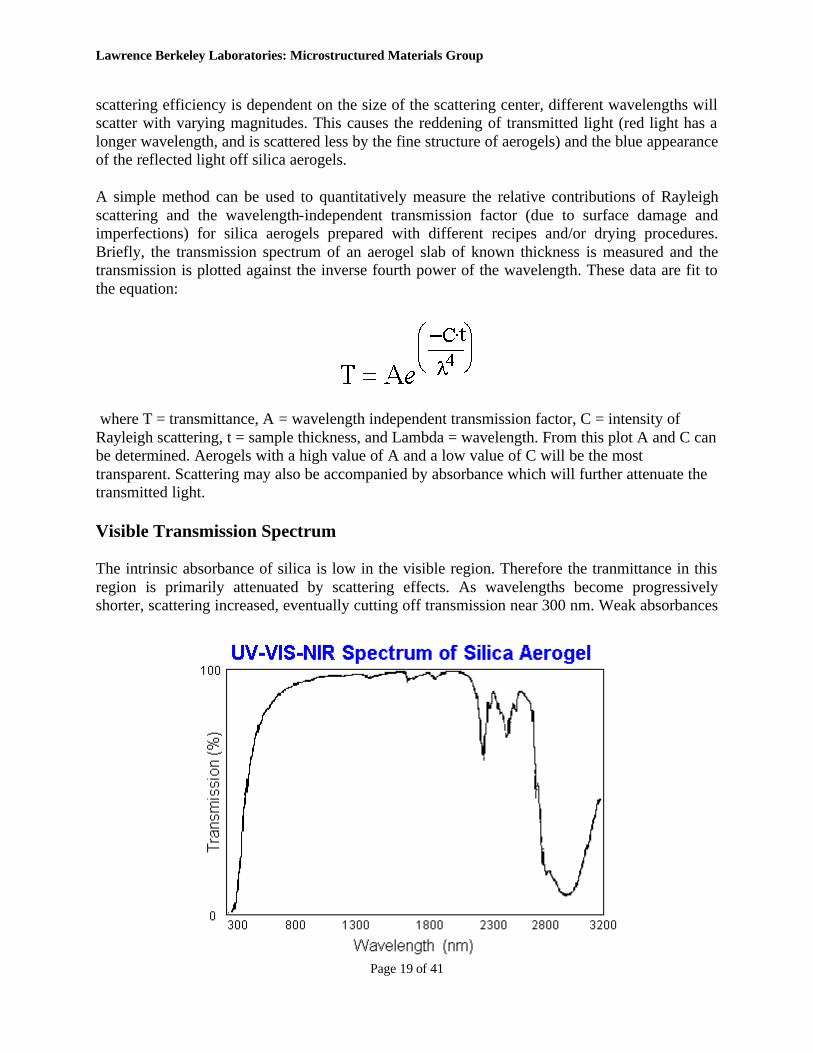
Visible Transmission Spectrum
The intrinsic absorbance of silica is low in the visible region. Therefore the tranmittance in this region is primarily attenuated by scattering effects. As wavelengths become progressively shorter, scattering increased, eventually cutting off transmission near 300 nm. Weak absorbances
Lawrence Berkeley Laboratories: Microstructured Materials Group
Page 20 of 41
begin to appear in the near infrared, and again cuts off transmission around 2700-3200 nm.
There is then a "visible window" of transmission through silica aerogel that is an attractive feature of this material for daylighting applications.
Infrared Spectrum
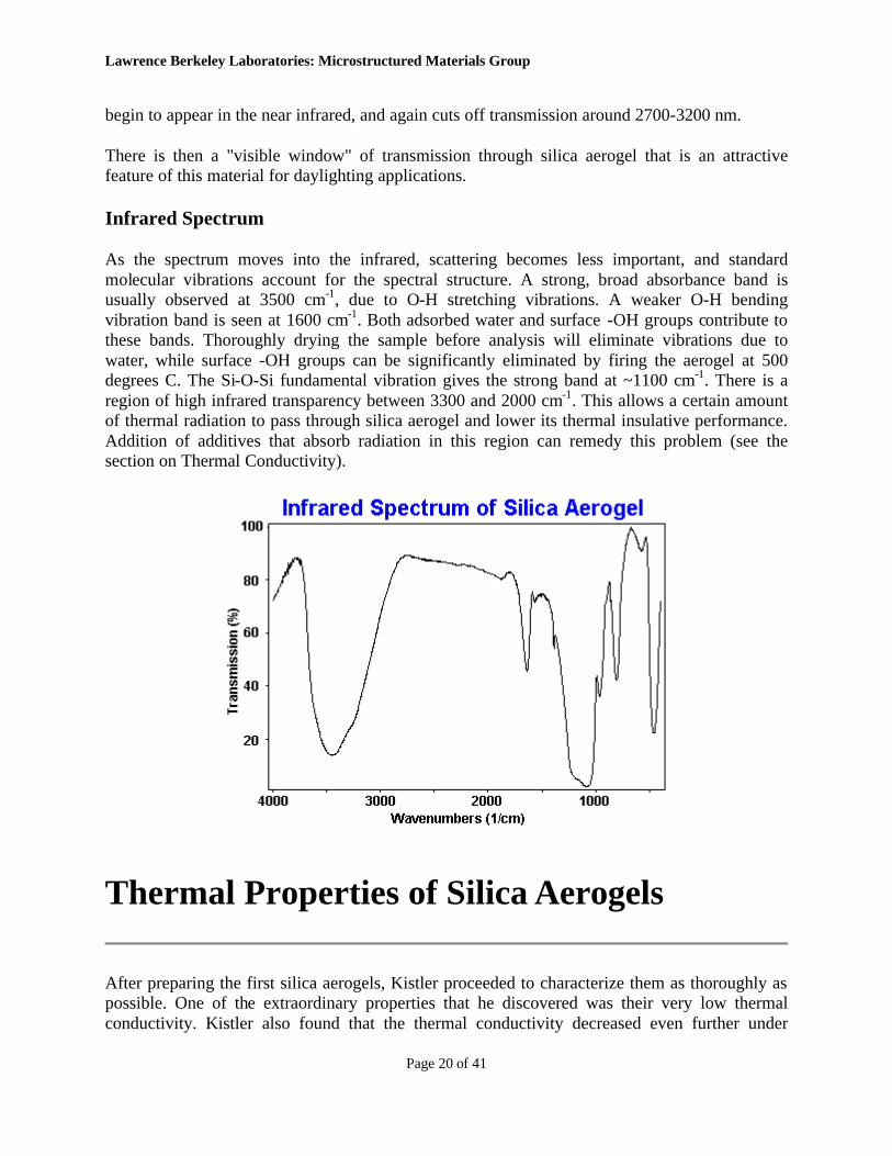
As the spectrum moves into the infrared, scattering becomes less important, and standard molecular vibrations account for the spectral structure. A strong, broad absorbance band is usually observed at 3500 cm-1, due to O-H stretching vibrations. A weaker O-H bending vibration band is seen at 1600 cm-1. Both adsorbed water and surface -OH groups contribute to these bands. Thoroughly drying the sample before analysis will eliminate vibrations due to water, while surface -OH groups can be significantly eliminated by firing the aerogel at 500 degrees C. The Si-O-Si fundamental vibration gives the strong band at ~1100 cm-1. There is a region of high infrared transparency between 3300 and 2000 cm-1. This allows a certain amount of thermal radiation to pass through silica aerogel and lower its thermal insulative performance. Addition of additives that absorb radiation in this region can remedy this problem (see the section on Thermal Conductivity).
Thermal Properties of Silica Aerogels
After preparing the first silica aerogels, Kistler proceeded to characterize them as thoroughly as possible. One of the extraordinary properties that he discovered was their very low thermal conductivity. Kistler also found that the thermal conductivity decreased even further under
Lawrence Berkeley Laboratories: Microstructured Materials Group
Page 21 of 41
vacuum. However, in the 1930's thermal insulation was a low priority and applications of aerogels in insulation systems was not pursued. The renaissance of aerogel technology around 1980 coincided with an increased concern for energy efficiency and the environmental effects of chlorofluorocarbons (CFC's). It was then readily apparent that silica aerogels were an attractive alternative to traditional insulation due to their high insulating value and environment-friendly production methods. Unfortunately, the production costs of the material were prohibitive to cost-sensitive industries such as housing. A significant research effort was undertaken, and is continuing, at several institutions worldwide (including Berkeley Lab) to circumvent this problem by increasing the insulative performance and lowering the production costs of silica aerogels.
The passage of thermal energy through an insulating material occurs through three mechanisms; solid conductivity, gaseous conductivity, and radiative (infrared) transmission. The sum of these three components gives the total thermal conductivity of the material. Solid conductivity is an intrinsic property of a specific material. For dense silica, solid conductivity is relatively high (a single-pane window transmits a large amount of thermal energy). However, silica aerogels possess a very small (~1-10%) fraction of solid silica. Additionally, the solids that are present consist of very small particles linked in a three-dimensional network (with many "dead-ends"). Therefore, thermal transport through the solid portion of silica aerogel occurs through a very tortuous path and is not particularly effective. The space not occupied by solids in an aerogel is normally filled with air (or another gas) unless the material is sealed under vacuum. These gases can also transport thermal energy through the aerogel. The pores of silica aerogel are open and allow the passage of gas (albeit with difficulty) through the material. The final mode of thermal transport through silica aerogels involves infrared radiation. A advantage of silica aerogels for insulation applications is their visible transparency (which will allow their use in windows and skylights). However, they are also reasonably transparent in the infrared (especially between 3-5 microns). At low temperatures, the radiative component of thermal transport is low, and not a significant problem. At higher temperatures, radiative transport becomes the dominant mode of thermal conduction, and must be dealt with. The infrared spectrum of silica aerogel can be found in the section on Optical Properties.
Attempting to calculate the total thermal conductivity arising from the sum of these three modes can be difficult, as they modes are coupled (changing the infrared absorbency of the aerogel also changes the solid conductivity, etc.). It is generally easier to measure the total thermal conductivity directly rather than predict the effect of changing one component. To achieve this, the Microstructured Materials Group at Berkeley Lab designed and built an economical, but accurate instrument for measuring the thermal conductivity of large aerogel panels. The Vacuum Insulation Conductivity Tester (On Rollers) -VICTOR, is a thin-film heater based device that can measure the thermal conductivity of panels up to 26 cm on edge, with pressures of various gases down to 0.01 Torr.
Minimizing the solid component of thermal conductivity
There is little that can be done to reduce thermal transport through the solid structure of silica aerogels. Lower density aerogels can be prepared (as low as 0.003 g/cm3), which reduces the amount of solid present, but this leads to aerogels that are mechanically weaker. Additionally, as
Lawrence Berkeley Laboratories: Microstructured Materials Group
Page 22 of 41
the amount of solids decreases the mean pore diameter increases (with an increase in the gaseous component of the conductivity). These are, therefore, generally not suitable for insulation applications. However, as noted above, the tortuous solid structure of silica aerogels leads to a intrinsically low thermal transport. Granular aerogels have an extremely low solid conductivity component. This is due to the small point of contact between granules in an aerogel bed. However, in granular aerogel, the inter-granule voids increase the overall porosity of the material thereby requiring a higher vacuum to achieve the maximum performance (see below).
Minimizing the gaseous component of thermal conductivity.
A typical silica aerogel has a total thermal conductivity of ~0.017 W/mK (~R10/inch). A major portion of this energy transport results from the gases contained within the aerogel. This is the transport mode that is most easily controllable. As a consequence of their fine pore structure, the mean pore diameter of an aerogel is similar in magnitude to the mean free path of nitrogen (and oxygen) molecules at standard temperatures and pressures. If the mean free path of a particular gas were longer than the pore diameter of an aerogel, the gas molecules would collide more frequently with the pore walls than with each other. If this were the case, the thermal energy of the gas would be transferred to the solid portion of the aerogel (with its low intrinsic conductivity). Lengthening the mean free path relative to the mean pore diameter can be accomplished in three ways; by filling the aerogel with a gas with a lower molecular mass (and a longer mean free path) than air, by reducing the pore diameter of the aerogel, and by lowering the gas pressure within the aerogel.
The first of these methods is generally not practical, as light gases are relatively expensive and would eventually escape the system. Increasing the density of the aerogel can reduce the mean pore diameter. However, any benefit from a lower gaseous conductivity component is counteracted by an increase in the solid conductivity component. The pore diameter can be reduced somewhat (while keeping the aerogel's density constant) by using the two-step process to prepare the aerogel (see the section on Aerogel Preparation). The greatest improvement is found by reducing the gas pressure. Vacuum insulations are commonplace in various products (such as Thermos bottles). These systems generally require a high vacuum to be maintained indefinitely to achieve the desired performance. In the case of aerogels, however, it is only necessary to reduce the pressure enough to lengthen the mean free path of the gas relative to the mean pore diameter. This occurs for most aerogels at a pressure of about 50 Torr. This is a very modest vacuum that can be easily obtained and maintained (by sealing the aerogel in a light plastic bag).
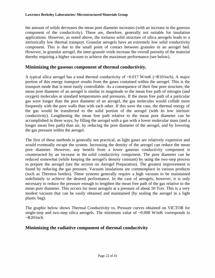
The graphic below shows Thermal Conductivity vs. Pressure curves obtained on VICTOR for single-step and two-step silica aerogels. The minimum value of ~0.008 W/mK corresponds to ~R20/inch.
Minimizing the radiative component of thermal conductivity
Lawrence Berkeley Laboratories: Microstructured Materials Group
Page 23 of 41
As noted above, radiative component of thermal conductivity becomes more important as temperatures increase. If silica aerogels are to be used at temperatures above 200 degree C, this mode of energy transport must be suppressed. This can be accomplished by adding an additional component to the aerogel, either before or after supercritical drying. (See the section on Composite Materials). The second component must either absorb or scatter infrared radiation. A major challenge for this process is to add a component that does not interfere with the mechanical integrity of the aerogel or increase its solid conductivity. One of the most promising
Lawrence Berkeley Laboratories: Microstructured Materials Group
Page 24 of 41
additives is elemental carbon. Carbon is an effective absorber of infrared radiation and, in some cases, actually increases the mechanical strength of the aerogel.
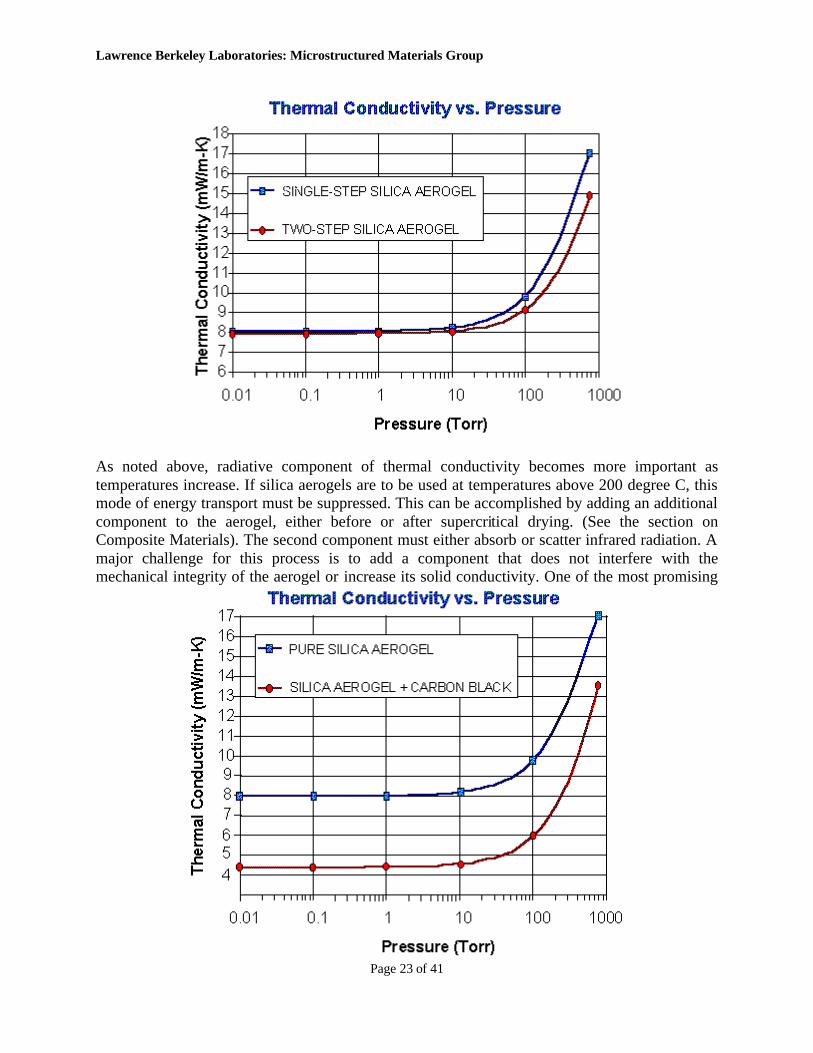
The graphic above shows Thermal Conductivity vs. Pressure curves obtained on VICTOR for pure single-step silica aerogel and single-step silica aerogel with 9% (wt/wt) carbon black. At ambient pressure the addition of carbon lowers the thermal conductivity from 0.017 to 0.0135 W/mK. The minimum value for the carbon composite of ~0.0042 W/mK corresponds to ~R30/inch.
Silica Aerogel Nanocomposite Materials
It was readily apparent to early researchers working on aerogels that they were ideal for use in composite materials. However, with much fundamental research needed into the preparation and properties of aerogels, this area has only recently been explored. In this discussion "composite" is used in the broadest sense of the term, where the final product consists of a "substrate" (the silica aerogel) and one or more additional phases (of any composition or scale). As all the materials considered here have a silica aerogel substrate, there is always at least one phase with physical structures with dimensions on the order of nanometers (the particles and pores of the aerogel). The additional phases may also have nanoscale dimensions, or may be larger (up to centimeters). Because of this the materials can legitimately be classified as "nanocomposites". There are generally three routes to aerogel nanocomposites: addition of the second component during the sol-gel processing of the material (before supercritical drying), addition of the second component through the vapor phase (after supercritical drying), and chemical modification of the aerogel backbone through reactive gas treatment.
Aerogel nanocomposites through Sol-Gel processing
This approach is the logical first route to aerogel nanocomposites and can produce many varieties of composites. There are, however, limitations to these procedures. Simply stated, a non-silica material is added to the silica sol before gelation. This added material may be a soluble organic or inorganic compound, insoluble powders, polymers, biomaterials, bulk fibers, woven cloths, or porous preforms. In all cases, the additional components must withstand the subsequent process steps used to form the aerogel (alcohol soaking, and supercritical drying). The conditions encountered in the CO2 drying process are milder than the alcohol drying process and are more amenable to forming composites. If the added components are bulk, insoluble materials (such as carbon fibers or mineral powders), steps must be taken to prevent the settling of the insoluble phase before gelation. This can often be accomplished by gently agitating the mixture until gelation is imminent. The silica aerogel with the best Thermal Properties results from the addition of a small amount of carbon black to the sol using this technique.
The addition of soluble inorganic or organic compounds to the sol provides a virtually unlimited number of possible composites. There are two criteria that must be met to prepare a composite by this route. First, the added component must not interfere with the gelation chemistry of the
Lawrence Berkeley Laboratories: Microstructured Materials Group
Page 25 of 41
silica precursor. This is difficult to predict in advance, but rarely a problem if the added component is reasonably inert. The second problem encountered in this process is the leaching out of the added phases during the alcohol soak or supercritical drying steps. This can be a significant impediment if a high loading of the second phase is desired in the final composite. When the addend component is a metal complex, it is often useful to use a binding agent, such as (CH3O)3SiCH2CH2NHCH2CH2NH2. This can bind with the silica backbone through the hydrolysis of its methoxysilane groups and chelate the metal complex with its dangling diamine. This general approach has been used by several research groups to prepare nanocomposites of silica aerogels or xerogels. After the gel has been dried, the resulting composite consists of a silica aerogel with metal ions atomically dispersed throughout the material. Thermal post-processing induces thermal diffusion and reduction of the metal ions, forming nanometer-scale metal particles within the aerogel matrix. These composites are being extensively studies for use a catalysts for gas-phase reactions.
Aerogel nanocomposites through Chemical Vapor Infiltration.
The open Pore Network of silica aerogels allows for easy transport of vapors throughout the entire volume of the material. This provides another route to an aerogel nanocomposite. Virtually any compound with at least a slight vapor pressure can be deposited throughout a silica aerogel. In fact, silica aerogels should be stored in a clean environment to prevent the unwanted absorption of volatile pollutants. To prevent subsequent desorption of the added phase, it is useful to convert the adsorbed material into a non-volatile phase by thermal or chemical decomposition. This can be done during, or after the initial deposition. The Microstructured Materials Group has prepared a wide variety of aerogel nanocomposites using this process, including:
Silica aerogel-Carbon composites. These have been prepared through the decomposition of various hydrocarbon gases at high temperatures. However, due to the fine structure of silica aerogels, the decomposition take place at a much lower temperature (200-450 degrees C) than the corresponding decomposition in the absence of the aerogel. Carbon loadings ranging from 1-800% have been observed. Surprisingly, at lower loadings, the carbon deposition is relatively uniform throughout the volume of monolithic aerogel slabs. At higher loadings, the carbon begins to localize at the exterior surface of the composite monolith. Interesting aspects of these composites include electrical conductivity at higher loadings, and mechanical strengthening of the composite relative to the original aerogel. Silica aerogel-Silicon composites. The thermal decomposition of various organosilanes on a silica aerogel forms deposits of elemental silicon. In this case the rapid decomposition of the silane precursor leads to deposits localized near the exterior surface of the aerogel substrate. Thermal annealing of the composite induces crystallization of the silicon. The resulting composite, with 20-30 nm diameter silicon particles, exhibits strong visible photoluminescence at 600 nm. Silica aerogel-Transition Metal composites. Organo-transition metal complexes are idea precursors for this type of composite. Even the least volatile of these possess a sufficient vapor pressure to be deposited within an aerogel. Under controlled conditions, these deposit uniformly throughout the entire volume of the aerogel monolith. Typically, the metal compounds are then thermally degraded to their base metals. These intermediate composites are generally highly
Lawrence Berkeley Laboratories: Microstructured Materials Group
Page 26 of 41
reactive, due to the disperse nature of the metallic phase, and can be easily converted to metal oxides, sulfides, or halides. This process can be repeated several times to increase the loading of the metallic phase. Typically composites prepared in this way possess crystals of the desired metal compound on the order of 5-100 nm in diameter.
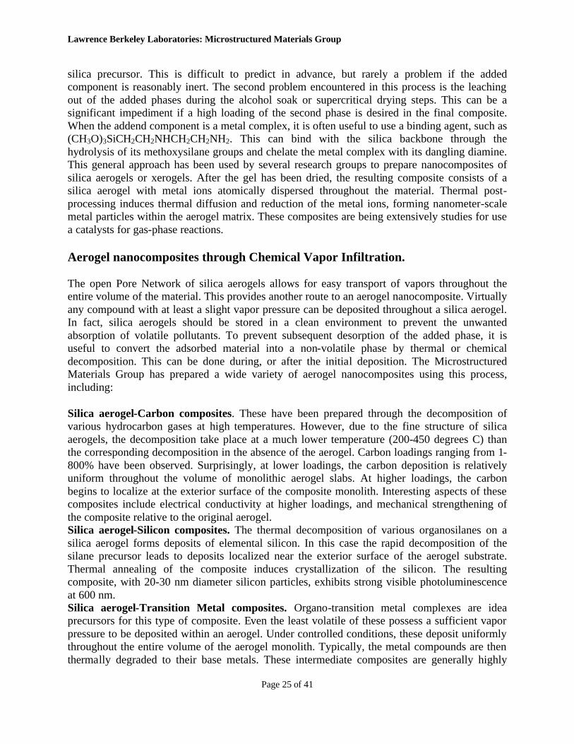
The graphic below displays the magnetization/demagnetization curve for a silica aerogel/Fe3O4 composite prepared by this process. The curve shows that the composite is a "soft" ferromagnetic material. The magnetite crystals in this composite are 20-60 nm in diameter. Many appear to be single domain, as observed by electron microscopy.
The Microstructured Materials Group has a patent pending on various aspects of this process, which is available for Technology Transfer
Aerogel nanocomposites through Energized Gas Treatment.
The Microstructured Materials Group has recently discovered a simple process that can alter the chemical structure of the silica (or other oxide) backbone of an aerogel. This process utilizes an energized reducing (or other) gas to form thin films of new material on the interior surface of the aerogel. The techniques used in this case are similar to standard plasma methods. However, the nanoscale pore structure of silica aerogels prohibit the formation of a plasma within an aerogel. Nevertheless, the centers of thick monoliths are affected by this process. In the simplest case, silica aerogel monoliths are partially reduced by energized hydrogen. The resulting composite consists of a silica aerogel with a thin layer of oxygen-deficient silica (SiOx) on the interior surface. As with other reduced silica materials, this material exhibits strong visible photoluminescence at 490-500 nm when excited by ultraviolet (330 nm) light. However, the process used in this case is relatively gentle, and does not alter the physical shape or optical
Lawrence Berkeley Laboratories: Microstructured Materials Group
Page 27 of 41
transparency of the original aerogel. This composite is the basis for the aerogel Optical Oxygen Sensor.
The Microstructured Materials Group has a patent pending on this process, which is available for Technology Transfer.
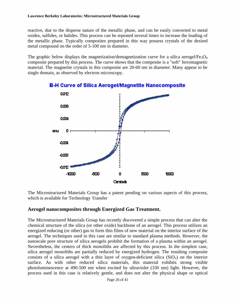
As noted above, several aerogel nanocomposites exhibit strong visible photoluminescence. The spectra shown below are for the silicon nanoparticles/silica aerogel (red emitter) and gas-treated reduced silica aerogel composite (blue-green emitter)
Optical Oxygen Sensor Based on Silica Aerogel
Silica aerogels are ideal materials for active and passive components in optical sensors. Their visible transparency, high surface area, facile transport of gases through the material, thermal and chemical stability, and ability to be filled with additional active phases are the key properties that aerogels bring to sensor applications. The Microstructured Materials Group has recently discovered a new process that induces a permanent, visible photoluminescence in silica aerogels (see the section on aerogel composite materials). Shortly after these materials were prepared, it was observed that the intensity of the photoluminescence was indirectly proportional to the amount of gaseous oxygen within the aerogel. The quenching of photoluminescence by oxygen is a phenomenon that is frequently observed in many luminescent materials.
Lawrence Berkeley Laboratories: Microstructured Materials Group
Page 28 of 41
In simple terms, photoluminescence occurs when a material absorbs a photon of sufficient energy. The entity that absorbs the photon may be a discrete molecule, or a defect center in a solid-state material, and if often referred to a "carrier". When the photon has been absorbed, the carrier is moved into a high energy, "excited" state. The carrier will then relax back to its ground state after certain length of time. This "lifetime" of the excited state is usually on the order of nanoseconds to microseconds. The mechanism by which the carrier relaxes determines whether the photoluminescence is termed "fluorescence" or "photoluminescence". If an oxygen molecule collides with a carrier while it is in its excited state, the oxygen molecule will absorb the excess energy of the carrier and quench the photoluminescence. The oxygen molecule absorbs the energy and undergoes a triplet-to-singlet transition, while the carrier undergoes a non-radiative relaxation. The efficiency of the photoluminescence quenching is , therefore, determined by the number of collisions between the material containing the carrier, and oxygen molecules. As the collision frequency of gases is determined by the number of molecules present, the pressure (P), and temperature (T), at a given P and T, the quenching efficiency, and, consequently, the photoluminescence intensity will be determined by the concentration of oxygen in the atmosphere surrounding the material.
Oxygen sensors based on this principle have been extensively studied. The most common sensor elements studied are those based on an organic or inorganic compound suspended in a thin silicone membrane. Advantages of using an aerogel-based sensor element over these systems include a more rapid response time (due to rapid diffusion of gases through the aerogel pore network), and improved resistance to photo-bleaching (as the photoluminescence is caused by stable defect centers in SiO2). The Microstructured Materials Group has built a prototype oxygen sensor based on this technology. The sensor is intended to perform as low cost, moderate sensitivity device operating most effectively in the concentration range of 0-30% oxygen. The sensor operates independently of the nature of the other gases present in the feed gas and of the
Lawrence Berkeley Laboratories: Microstructured Materials Group
Page 29 of 41
feed gas flow rate. The prototype sensor has been sensor has been successfully operated over a temperature range of -25 to +85 degrees C (this range is based on other experimental limitations of the system, the actual usable range is larger). The highest sensitivity is observed at lower temperatures.
The prototype sensor uses a Hg-arc lamp for excitation (330 nm), and a Si photodiode for detection of the emission (500nm). The prototype design can be easily miniaturized, and a device can be designed with built-in pressure and temperature compensation.
This sensor is available for technology-transfer (see the Aerogel Technology Transfer Page)
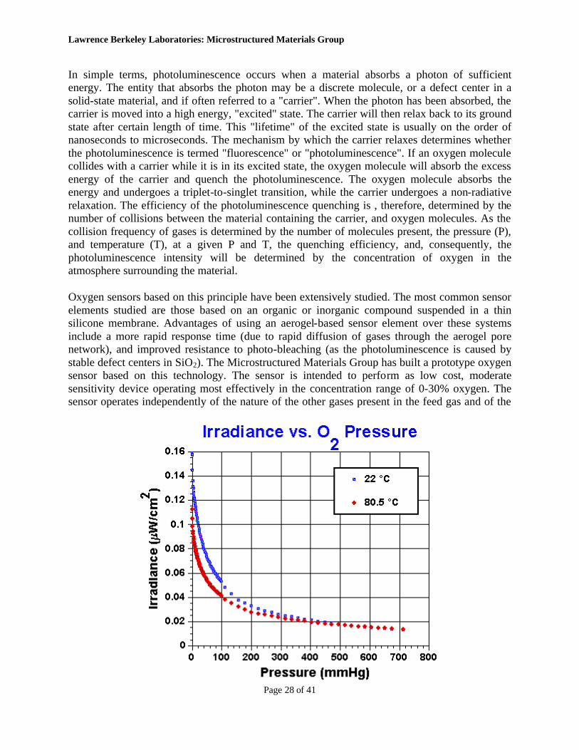
The graphic below plots the measured photoluminescence intensity (irradiance) vs oxygen pressure (concentration gives a similar plot) at two temperatures using the prototype sensor.
Silica Aerogels: Technology-Transfer Opportunities/Commercial Availability
Technology Transfer
As an institution funded by the U. S. Government, Berkeley Lab actively seeks technology-transfer arrangements that will be mutually beneficial to Berkeley Lab and commercial entities. The following technologies developed by the Microstructured Materials Group are available for direct transfer:
• Methods of producing aerogel-based composite materials via chemical vapor infiltration methods.
• Methods of producing photoluminescent silica aerogel and other aerogels with altered chemical compositions.
• Optical oxygen sensor based on photoluminescent silica aerogel.
Commercial Availability
In 1994, the Microstructured Materials Group entered into a Cooperative Research And Development Agreement with Aerojet Corp. of Sacramento, California, USA and several other partners. This agreement was supported by an ARPA-TRP grant and focused on development of a pilot-scale aerogel production plant. At the completion of the project in 1995, Aerojet idled this facility and has no current plans to continue in this area.
Lawrence Berkeley Laboratories: Microstructured Materials Group
Page 30 of 41
Other potential U.S. sources of aerogels are Nanopore, in Albuquerque, N.M. which focuses on lower-cost granular aerogels and Aspen Systems, in Marlboro, MA which produces flexible aerogel-based insulation for cryogenic systems.
A new venture, Ocellus, in the San Fransisco area, is currently selling small quantities of R-F, carbon and silica aerogels. They are available through MarkeTech International.
In Europe, Airglass in Lund, Sweden has made batch quantities of aerogels for many years, focusing on serving the needs of the high energy physics community.
Cabot Corp. will soon introduce commercial-scale quantities of granular, ambient-pressure dried aerogel products.
The TASSI company in Ohio is developing various oxide materials for uses such as air purification and catalysis.
Note: The Microstructured Materials Group has a limited, and ever decreasing, stock of silica aerogel monoliths of various sizes. In the past we have provided demonstration samples to interested parties. Regrettably, we can no longer continue this practice. We may provide samples to organizations interested in collaborative research with Berkeley Lab, or to assist in development of applications of aerogels with realistic commercial potential. We are sorry that we will not be able to help artists, designers, high schools, etc. unless there are extraordinary circumstances.
A Partial Bibliography for Silica Aerogels
Note: There are well over one thousand scholarly papers dealing with aerogels. The partial list below gives representative examples and an indication of the breadth of this field.
The International Symposia on Aerogels | Papers by Microstructured Materials Group Members | Thermal Properties | Optical Phenomena | Mechanical Properties | Cherenkov Counter Applications | Miscellaneous
• THE INTERNATIONAL SYMPOSIA ON AEROGELS (ISA) o 1st ISA: Wurzburg, Germany September 23-25 1985
Proceedings: "Aerogels" Ed. J. Fricke Springer Proceedings in Physics 6, Springer-Verlag (Berlin) 1986
Lawrence Berkeley Laboratories: Microstructured Materials Group
Page 31 of 41
o 2nd ISA: Montpellier, France September 21-23, 1988 Proceedings: Colloque de Physique (Supplement au Journal de Physique, FASC. 4), C4-1989
o 3rd ISA: Wurzburg, Germany September 30 - October 2, 1991 Proceedings: Journal of Non-Crystalline Solids vol. 145, 1992
o 4th ISA: Berkeley, California, USA. September 19-21, 1994 Proceedings: Journal of Non-Crystalline Solids vol. 185-6, 1995
o 5th ISA: Montpellier, France September 8-10, 1997 Proceedings: Journal of Non-Crystalline Solids vol. 225, 1998
o 6th ISA: Albuquerque, N.M., USA October 8-11, 2000 Proceedings: Journal of Non-Crystalline Solids vol. 285, 2001
• PAPERS BY MICROSTRUCTURED MATERIALS GROUP MEMBERS o Ayers, M.R. and Hunt. A.J.
2001 Observation of the Aggregation Behavior of Silica Sols Using Laser Speckle Contrast Measurements. Journal of Non-Crystalline Solids, 290:122-128
o Ayers, M.R. and Hunt. A.J. 2001 Synthesis and Properties of Chitosan-Silica Hybrid Aerogels. Journal of Non-Crystalline Solids, 285:123-127
o Hunt. A.J., and Ayers, M.R. 2001 Investigations of Silica Alcogel Using Coherent Light. Journal of Non-Crystalline Solids, 285:162-166.
o Hunt. A.J. 1998 Light Scattering for Aerogel Characterization Journal of Non-Crystalline Solids, 225:303-306
o Ayers, M.R. and Hunt. A.J. 1998 Molecular Oxygen Sensor Based on Photoluminescent Silica Aerogel. Journal of Non-Crystalline Solids, 225:343-347
o Ayers, M.R. and Hunt. A.J. 1998 Light Scattering Studies of UV-Catalyzed Gel and Aerogel Structure, Journal of Non-crystalline Solids , 225:325-329
o Ayers, M. R. and Hunt A.J. 1998 Titanium Oxide Aerogels Prepared from Titanium Metal and Hydrogen Peroxide. Materials Letters, 34:290-293
o Ayers, M. R. and Hunt A.J. 1998 Visibly Photoluminescent Silica Aerogels. Journal of Non-Crystalline Solids, 217:229-235
o Ayers, M. R. Song, X. Y., and Hunt A. J. 1996 Preparation of Nanocomposite Materials Containing WS2, d-WN, Fe3O4, or Fe9S10 in a Silica Aerogel Host. Journal of Materials Science 31:6251-6257.
o Zeng, S. Q., A. Hunt, and R. Greif 1995 Theoretical Modeling of Carbon Content to Minimize Heat Transfer In Silica Aerogel. Journal of Non-Crystalline Solids, 186: 271-277.
Lawrence Berkeley Laboratories: Microstructured Materials Group
Page 32 of 41
o Song, X. Y., W. Q. Cao, M. R. Ayers, and A. J. Hunt 1995 Carbon Nanostructures In Silica Aerogel Composites. Journal of Materials Research 10: 251-254.
o Zeng, S. Q., A. Hunt, and R. Greif 1995 Transport Properties of Gas In Silica Aerogel. Journal of Non-Crystalline Solids 186: 264-270.
o Hunt, A. J., M. R. Ayers, and W. Q. Cao 1995 Aerogel Composites Using Chemical Vapor Infiltration. Journal of Non-Crystalline Solids 185: 227-232.
o Lee, D., P. C. Stevens, S. Q. Zeng, and A. J. Hunt 1995 Thermal Characterization of Carbon-Opacified Silica Aerogels. Journal of Non-Crystalline Solids 186: 285-290.
o Cao, W. Q., and A. J. Hunt 1994 Photoluminescence of Chemically Vapor Deposited Si On Silica Aerogels. Applied Physics Letters 64: 2376-2378.
o Song, X. Y., W. Cao, and A. J. Hunt 1994 AEM and HREM evaluation of carbon nanostructures in silica aerogels, Spring meeting of the Materials Research Society; pp. (6 p). San Francisco, CA (United States): Lawrence Berkeley Lab., California (United States)
o Cao, W. Q., and A. J. Hunt 1994 Improving the Visible Transparency of Silica Aerogels. Journal of Non-Crystalline Solids 176: 18-25.
o Cao, W. Q., and A. J. Hunt 1994 Thermal Annealing of Photoluminescent Si Deposited On Silica Aerogels. Solid State Communications 91: 645-648.
o Zeng, S. Q., A. J. Hunt, W. Cao, and R. Greif 1994 Pore size distribution and apparent gas thermal conductivity of silica aerogel. Journal of Heat Transfer 116: 756-759.
o Hunt, A. J., C. A. Jantzen, W. Cao, R. S. Graves, and D. C. Wysocki 1991 Aerogel. Gatlinburg, TN (United States): Philadelphia, PA (United States) ASTM (Symposium on insulation materials: testing and applications,
o Hunt, A., K. Lofftus, W. H. Bloss, and F. Pfisterer 1988 Silica aerogel, a transparent high performance insulator. Hamburg, F.R. Germany: Pergamon Press,Oxford, GB (International Solar Energy Society biennial congress on advances in solar energy technology,
o Tewari, P. H., A. J. Hunt, K. D. Lofftus, J. G. Lieber, C. J. Brinker, D. E. Clark, and D. R. Ulrich 1986 Microstructural studies of transparent silica gels and aerogels. Palo Alto, CA, USA: Materials Research Society,Pittsburgh, PA (Materials Research Society spring meeting
o Tewari, P. H., K. D. Lofftus, and A. J. Hunt 1985 Structure and chemistry of sol-gel derived transparent silica aerogel, 2. international conference on ultrastructure processing of ceramics, glasses and composites; pp. 17. Daytona Beach, Florida, USA: Lawrence Berkeley Lab., California (USA)
Lawrence Berkeley Laboratories: Microstructured Materials Group
Page 33 of 41
o Hunt, A. J., R. E. Russo, P. H. Tewari, and K. D. Lofftus 1985 Aerogel: a transparent insulator for solar applications, INTERSOL '85 - Solar energy--the diverse solution; pp. 8. Montreal, Canada: Lawrence Berkeley Lab., California (USA)
o Hunt, A., P. Berdahl, K. Lofftus, R. Russo, and P. Tewari 1985 Advances in transparent insulating aerogels for windows, Solar buildings: realities for today - trends for tomorrow; pp. 138-141. Washington, DC, USA: Lawrence Berkeley Lab., California, MCC Associates, Inc., Silver Spring, MD (USA)
o Hunt, A., R. Russo, P. Tewari, K. Lofftus, E. Bilgen, and K. G. T. Hollands 1985 Aerogel: A transparent insulator for solar applications. Montreal, Canada: Pergamon Books Inc.,Elmsford, NY (INTERSOL '85 - Solar energy--the diverse solution,
o Selkowitz, S. E., A. Hunt, C. M. Lampert, and M. D. Rubin 1984 Advanced optical and thermal technologies for aperture control, Passive and hybrid solar energy update; pp. 10-19. Washington, DC, USA: Lawrence Berkeley Lab., Californialifornia, U.S. Department of Energy Assistant Secretary for Conservation and Renewable Energy, Washington, DC. Passive and Hybrid Solar Energy Division
o Hunt, A. J., and P. Berdahl 1984 Structure data form light scattering studies of aerogel. Mater. Res. Soc. Symp. Proc. : 275-280.
o Hunt, A., P. Berdahl, K. Lofftus, R. Russo, and P. Terwari 1984 Advances in transparent insulating aerogels for windows, Passive and hybrid solar energy update; pp. 47-50. Washington, DC, USA: Lawrence Berkeley Lab., Californialifornia, U.S. Department of Energy Assistant Secretary for Conservation and Renewable Energy, Washington, DC. Passive and Hybrid Solar Energy Division
o Hunt, A. J. 1983 Light-scattering studies of silica aerogels, International conference on ultrastructure processing of ceramics, glasses and composites; pp. 15. Gainesville, FL, USA: Lawrence Berkeley Lab., California (USA)
• THERMAL PROPERTIES o Rettelbach, R., J. Sauberlich, S. Korder, and J. Fricke
1995 Thermal Conductivity of Ir-Opacified Silica Aerogel Powders Between 10 K and 275 K. Journal of Physics D-Applied Physics 28: 581-587.
o Rettelbach, T., J. Sauberlich, S. Korder, and J. Fricke 1995 Thermal Conductivity of Silica Aerogel Powders At Temperatures From 10 to 275 K. Journal of Non-Crystalline Solids 186: 278-284.
o Hrubesh, L. W., and J. F. Poco 1995 Thin Aerogel Films For Optical, Thermal, Acoustic and Electronic Applications. Journal of Non-Crystalline Solids 188: 46-53.
Lawrence Berkeley Laboratories: Microstructured Materials Group
Page 34 of 41
o Hrubesh, L. W., and R. W. Pekala 1994 Thermal properties of organic and inorganic aerogels. Journal of Materials Research 9: 731-738.
o Zeng, S. Q., A. J. Hunt, W. Cao, and R. Greif 1994 Pore size distribution and apparent gas thermal conductivity of silica aerogel. Journal of Heat Transfer 116: 756-759.
o Reiss, H. 1992 Heat transfer in thermal insulations. Physikalische Blaetter 48: 617-622.
o Bernasconi, A., T. Sleator, D. Posselt, J. K. Kjems, and H. R. Ott 1992 Low-Temperature Specific Heat and Thermal Conductivity of Silica Aerogels. Journal of Non-Crystalline Solids 145: 202-206.
o Scheuerpflug, P., M. Hauck, and J. Fricke 1992 Thermal Properties of Silica Aerogels Between 1.4-K and 330-K. Journal of Non-Crystalline Solids 145: 196-201.
o Bernasconi, A., T. Sleator, D. Posselt, J. K. Kjems, and H. R. Ott 1992 Dynamic Properties of Silica Aerogels As Deduced From Specific-Heat and Thermal-Conductivity Measurements. Physical Review B-Condensed Matter 45: 10363-10376.
o Posselt, D., J. K. Kjems, A. Bernasconi, T. Sleator, and H. R. Ott 1991 The Thermal Conductivity of Silica Aerogel In the Phonon, the Fracton and the Particle-Mode Regime. Europhysics Letters 16: 59-65.
o Scheuerpflug, P., H. J. Morper, G. Neubert, and J. Fricke 1991 Low-Temperature Thermal Transport In Silica Aerogels. Journal of Physics D-Applied Physics 24: 1395-1403.
o Xianping, Lu, Wang Peng, D. Buettner, U. Heinemann, O. Nilsson, J. Kuhn, and J. Fricke
o 1991 Thermal transport in opacified monolithic silica aerogels. High Temperatures High Pressures 23: 431-436.
o Sleator, T., A. Bernasconi, D. Posselt, J. K. Kjems, and H. R. Ott 1991 Low-Temperature Specific Heat and Thermal Conductivity of Silica Aerogels. Physical Review Letters 66: 1070-1073.
o Caps, R., G. Doll, J. Fricke, U. Heinemann, and J. Hetfleisch 1989 Thermal Transport In Monolithic Silica Aerogel. Journal De Physique 50: C4113-C4118.
o Fricke, J. 1989 Thermal insulation without CFC. Physik in Unserer Zeit 20: 189-191.
o Fricke, J., E. Hummer, H. J. Morper, and P. Scheuerpflug 1989 Thermal Properties of Silica Aerogels. Journal De Physique 50: C487-C497.
o Buettner, D., R. Caps, U. Heinemann, E. Huemmer, A. Kadur, and J. Fricke 1988 Thermal loss coefficients of low-density silica aerogel tiles. Sol. Energy 40: 13-15.
o Fricke, J., R. Caps, D. Buettner, U. Heinemann, E. Huemmer, and A. Kadur 1987 Thermal loss coefficients of monolithic and granular aerogel systems. Sol. Energy Mater. 16: 267-274.
Lawrence Berkeley Laboratories: Microstructured Materials Group
Page 35 of 41
• OPTICAL PHENOMENA o Hrubesh, L. W., and J. F. Poco
1995 Thin Aerogel Films For Optical, Thermal, Acoustic and Electronic Applications. Journal of Non-Crystalline Solids 188: 46-53.
o Zhu, L., Y. F. Li, J. Wang, and J. Shen 1995 Structural and Optical Characteristics of Fullerenes Incorporated Inside Porous Silica Aerogel. Chemical Physics Letters 239: 393-398.
o Emmerling, A., R. Petricevic, A. Beck, P. Wang, H. Scheller, and J. Fricke 1995 Relationship Between Optical Transparency and Nanostructural Features of Silica Aerogels. Journal of Non-Crystalline Solids 185: 240-248.
o Beck, A., W. Koerner, and J. Fricke 1994 Optical investigations of granular aerogel fills. Journal of Physics. D, Applied Physics 27: 13-18.
o Hotaling, S. P. 1993 Ultra-Low Density Aerogel Optical Applications. Journal of Materials Research 8: 352-355.
o Emmerling, A., P. Wang, G. Popp, A. Beck, and J. Fricke 1993 Nanostructure and Optical Transparency of Silica Aerogels. Journal De Physique Iv 3: 357-360.
o Platzer, W. J., and M. Bergkvist 1993 Bulk and surface light scattering from transparent silica aerogel. Solar Energy Materials and Solar Cells 31: 243-251.
o Wang, P., W. Korner, A. Emmerling, A. Beck, J. Kuhn, and J. Fricke 1992 Optical Investigations of Silica Aerogels. Journal of Non-Crystalline Solids 145: 141-145.
o Beck, A., O. Gelsen, P. Wang, and J. Fricke 1989 Light Scattering For Structural Investigations of Silica Aerogels and Alcogels. Journal De Physique 50: C4203-C4208.
o Lampert, C. M. 1987 Advanced optical materials for energy efficiency and solar conversion. Sol. Wind Technol. 4: 347-379.
o Hunt, A. J., and P. Berdahl 1984 Structure data form light scattering studies of aerogel. Mater. Res. Soc. Symp. Proc. : 275-280.
o Lampert, C. N. 1983 Solar optical materials for innovative window design. Int. J. Energy Res. 7: 359-374.
• MECHANICAL PROPERTIES o Hunt. A.J., and Ayers, M.R.
2001 Investigations of Silica Alcogel Using Coherent Light. Journal of Non-Crystalline Solids, 285:162-166.
Lawrence Berkeley Laboratories: Microstructured Materials Group
Page 36 of 41
o Woignier, T., J. Phalippou, H. Hdach, G. Larnac, F. Pernot, and G. W. Scherer 1992 Evolution of Mechanical Properties During the Alcogel Aerogel Glass Process. Journal of Non-Crystalline Solids 147: 672-680.
o Armand, A. C., and D. Guyomar 1992 Acoustic and Mechanical Characterization of Silica Aerogels. Journal De Physique Iii 2: 759-762.
o Hdach, H., T. Woignier, J. Phalippou, and G. W. Scherer 1990 Effect of Aging and pH On the Modulus of Aerogels. Journal of Non-Crystalline Solids 121: 202-205.
o Woignier, T., and J. Phalippou 1989 Scaling Law Variation of the Mechanical Properties of Silica Aerogels. Journal De Physique 50: C4179-C4184.
o Phalippou, J., T. Woignier, and R. Rogier 1989 Fracture Toughness of Silica Aerogels. Journal De Physique 50: C4191-C4196.
o Cross, J., R. Goswin, R. Gerlach, and J. Fricke 1989 Mechanical Properties of SiO2 - Aerogels. Journal De Physique 50: C4185-C4190.
• CHERENKOV RADIATION COUNTER APPLICATIONS o Adachi, I., T. Sumiyoshi, K. Hayashi, N. Iida, R. Enomoto, K. Tsukada, R.
Suda, S. Matsumoto, K. Natori, M. Yokoyama, and H. Yokogawa 1995 Study of a threshold Cherenkov counter based on silica aerogels with low refractive indices. Nuclear Instruments and Methods in Physics Research, Section A 355: 390-398.
o Ganezer, K. S., W. E. Keig, and A. F. Shor 1994 A simple high efficiency Cherenkov counter. IEEE Transactions on Nuclear Science 41: 336-342.
o Hasegawa, T., O. Hashimoto, T. Nagae, and M. Sekimoto 1994 A large silica aerogel Cherenkov counter for SKS. Nuclear Instruments and Methods in Physics Research, Section A 342: 383-388.
o Brajnik, D., S. Korpar, G. Medin, M. Staric, and A. Stanovnik 1994 Measurement of Sr-90 Activity With Cherenkov Radiation In a Silica Aerogel. Nuclear Instruments & Methods In Physics Research Section a-Accelerators Spectrometers Detectors and Associated Equipment 353: 217-221.
o Fields, D. E., H. Vanhecke, J. Boissevain, B. V. Jacak, W. E. Sondheim, J. P. Sullivan, W. J. Willis, K. Wolf, E. Noteboom, P. M. Peters, and R. Burke
o 1994 Use of Aerogel For Imaging Cherenkov Counters. Nuclear Instruments & Methods In Physics Research Section a-Accelerators Spectrometers Detectors and Associated Equipment 349: 431-437.
o Adachi, Ichiro 1994 R and D on Cherenkov counter based on silica aerogel with low refractive index. Hoshasen 20: 21-30.
Lawrence Berkeley Laboratories: Microstructured Materials Group
Page 37 of 41
o Lippert, C., R. Siebert, J. P. Didelez, J. Ernst, R. Frascaria, J. Y. Martel, and R. Skowron 1993 Particle discrimination in medium energy physics with an aerogel Cherenkov detector. Nuclear Instruments and Methods in Physics Research, Section A 333: 413-421.
o Onuchin, A., A. Shamov, Yu Skovpen, A. Vorobiov, A. Danilyuk, T. Gorodetskaya, and V. Kuznetsov 1992 The aerogel Cherenkov counters with wavelength shifters and phototubes. Nuclear Instruments and Methods in Physics Research, Section A 315: 517-520.
o Miskowiec, D., W. Ahner, E. Grosse, P. Senger, and W. Walus 1990 Aerogel Cherenkov detectors for the Kaon spectrometer. Verhandlungen der Deutschen Physikalischen Gesellschaft 25: 1520.
o Vincent, P., R. Debbe, A. Pfoh, and M. Abreu 1988 E802 aerogel Cherenkov detector. Nucl. Instrum. Methods Phys. Res. 272: 660-668.
o Carlson, P. 1986 Aerogel Cherenkov counters: Construction principles and applications. Nucl. Instrum. Methods Phys. Res. 248: 110-117.
o Poelz, G. 1986 Aerogel Cherenkov counters at DESY. Nucl. Instrum. Methods Phys. Res., Sect. A. 248: 118-129.
o Kawai, H., J. Haba, T. Homma, M. Kobayashi, K. Miyake, T. S. Nakamura, N. Sasao, Y. Sugimoto, M. Yoshioka, and M. Daigo 1985 Tests of a silica aerogel Cherenkov counter. Nucl. Instrum. Methods Phys. Res., Sect. A 228: 314-322.
o Maurer, K., G. Koebschall, K. Roehrich, C. Schmitt, and V. H. Walther 1984 Silica aerogel threshold Cherenkov counters for use at intermediate energies. Nucl. Instrum. Methods Phys. Res., Sect. A 224: 110-111.
o Fernandez, C., K. E. Johansson, M. Schouten, S. Tavernier, P. Ladron de Guevara, P. Herquet, J. Kesteman, and O. Pingot 1984 Performance of the silica aerogel Cherenkov detector used in the European Hybrid Spectrometer. Nucl. Instrum. Methods Phys. Res., Sect. A 225: 313-318.
o Yasumi, Shinjiro, and Hideyuki Kawai 1983 Silica aerogel Cherenkov counter. Nippon Butsuri Gakkaishi 38: 671-676.
o Poelz, G., and R. Riethmueller 1982 Preparation of silica aerogel for Cherenkov counters. Nucl. Instrum. Methods Phys. Res. 195: 491-503.
o Carlson, P. J., K. E. Johansson, J. Norrby, J. Kesteman, O. Pingot, S. Tavernier, and L. van Lancker 1982 Tests of an 18 module silica aerogel Cherenkov detector to be used in the European hybrid spectrometer. Nucl. Instrum. Methods Phys. Res. 192: 209-216.
o Burkhardt, H., P. Koehler, R. Riethmueller, B. H. Wiik, R. Fohrmann, J. Franzke, H. Krasemann, R. Maschuw, G. Poelz, and J. Reichardt 1981 TASSO gas and aerogel Cherenkov counters. Nucl. Instrum. Methods 184: 319-331.
Lawrence Berkeley Laboratories: Microstructured Materials Group
Page 38 of 41
o Trachsel, C., D. Perrin, and R. Schwarz 1981 Study of an aerogel Cherenkov detector with indirect light collection. Helv. Phys. Acta 53: 655-661.
o de Brion, J. P., A. Caillet, J. B. Cheze, J. Derre, G. Marel, E. Pauli, and C. Pigot 1981 Silica aerogel Cherenkov counter in a missing-mass experiment K/sup -/d ..-- >.. K/sup +/ + X at 1.4 GeV/c. Nucl. Instrum. Methods 179: 61-65.
o Carlson, P. J., K. E. Johansson, J. Kesteman, O. Pingot, J. Norrby, S. Tavernier, F. van den Bogaert, and L. van Lancker 1979 Increased photoelectron collection efficiency of a photomultiplier in an aerogel Cherenkov counter. Nucl. Instrum. Methods 160: 407-410.
o Bourdinaud, M., J. B. Cheze, and J. C. Thevenin 1976 Use of silica aerogel for Cherenkov radiation counter. Nucl. Instrum. Methods 136: 99-103.
• MISCELLANEOUS o Coddens, G., J. Dekinder, and R. Millet
1995 Time-of-Flight Inelastic Neutron Scattering Study of Liquid He-4 In Silica Aerogels. Journal of Non-Crystalline Solids 188: 41-45.
o Ehrburgerdolle, F., J. Dallamano, E. Elaloui, and G. M. Pajonk 1995 Relations Between the Texture of Silica Aerogels and Their Preparation. Journal of Non-Crystalline Solids 186: 9-17.
o Hua, D. W., J. Anderson, J. Digregorio, D. M. Smith, and G. Beaucage 1995 Structural Analysis of Silica Aerogels. Journal of Non-Crystalline Solids 186: 142-148.
o Jarzebski, A. B., and J. Lorenc 1995 Pore Network Connectivity and Effective Diffusivity of Silica Aerogels. Chemical Engineering Science 50: 357-360.
o Rogacki, G., and P. Wawrzyniak 1995 Diffusion of Ethanol-Liquid CO2 In Silica Aerogel. Journal of Non-Crystalline Solids 186: 73-77.
o Tsou, P. 1995 Silica Aerogel Captures Cosmic Dust Intact. Journal of Non-Crystalline Solids 186: 415-427.
o Yokogawa, H., and M. Yokoyama 1995 Hydrophobic Silica Aerogels. Journal of Non-Crystalline Solids 186: 23-29.
o Zhu, L., Y. F. Li, J. Wang, and J. Shen 1995 Intense Visible Light Emission From Fullerene-Doped Silica Aerogel. Journal of Applied Physics 77: 2801-2803.
o Zhu, L., Y. F. Li, J. Wang, and J. Shen 1995 Structural and Optical Characteristics of Fullerenes Incorporated Inside Porous Silica Aerogel. Chemical Physics Letters 239: 393-398.
o Schaefer, D. W., B. J. Olivier, C. Ashley, G. Beaucage, D. Richter, B. Farago, B. Frick, and D. A. Fischer
Lawrence Berkeley Laboratories: Microstructured Materials Group
Page 39 of 41
1994 Structure and Topology of Silica Aerogels During Densification. Journal of Non-Crystalline Solids 172: 647-655.
o Bruesch, P., F. Stucki, T. Baumann, P. Klugeweiss, B. Bruhl, L. Niemeyer, R. Strumpler, B. Ziegler, and M. Mielke 1993 Electrical and Infrared Dielectrical Properties of Silica Aerogels and of Silica Aerogel-Based Composites. Applied Physics a-Solids and Surfaces 57: 329-337.
o Gross, J., T. Schlief, and J. Fricke 1993 Ultrasonic Evaluation of Elastic Properties of Silica Aerogels. Materials Science and Engineering a-Structural Materials Properties Microstructure and Processing 168: 235-238.
o Igarashi, K., K. Tajiri, Y. Tai, and S. Tanemura 1993 Structural Study By Dsc, Saxs, and Raman Spectroscopy of Silica Aerogel. Zeitschrift Fur Physik D-Atoms Molecules and Clusters 26: S207-S209.
o Kralj, S., G. Lahajnar, A. Zidansek, N. Vrbancickopac, M. Vilfan, R. Blinc, and M. Kosec 1993 Deuterium Nmr of a Pentylcyanobiphenyl Liquid Crystal Confined In a Silica Aerogel Matrix. Physical Review E 48: 340-349.
o Pauthe, M., F. Despetis, and J. Phalippou 1993 Hydrophobic Silica CO2 Aerogels. Journal of Non-Crystalline Solids 155: 110-114.
o Buckley, A. M., and M. Greenblatt 1992 The Preparation and Characterisation of Silica Aerogels and Xerogels Doped With Transition Metal Species. Journal of Non-Crystalline Solids 146: 97-110.
o Buckley, A. M., and M. Greenblatt 1992 A Comparison of the Microstructural Properties of Silica Aerogels and Xerogels. Journal of Non-Crystalline Solids 143: 1-13.
o Courtens, E., and R. Vacher 1992 Structure and Dynamics of Silica Aerogels. Philosophical Magazine B-Physics of Condensed Matter Structural Electronic Optical and Magnetic Properties 65: 347-355.
o Damrau, U., H. C. Marsmann, O. Spormann, and P. Wang 1992 Si-29 Mas-Nmr Investigations of Silica Aerogels. Journal of Non-Crystalline Solids 145: 164-167.
o Dasilva, A., P. Donoso, and M. A. Aegerter 1992 Properties of Water Adsorbed In Porous Silica Aerogels. Journal of Non-Crystalline Solids 145: 168-174.
o Duval, E., A. Boukenter, T. Achibat, B. Champagnon, J. Serughetti, and J. Dumas 1992 Structure of Silica Aerogels and Vibrational Dynamics In Fractal Materials and Glasses - Electron Microscopy and Low-Frequency Raman Scattering. Philosophical Magazine B-Physics of Condensed Matter Structural Electronic Optical and Magnetic Properties 65: 181-189.
Lawrence Berkeley Laboratories: Microstructured Materials Group
Page 40 of 41
o Ehrburgerdolle, F., M. Holz, C. Mauzac, J. Lahaye, and G. M. Pajonk 1992 Characterization of the Porous Texture of Aerogel, Precipitated and Pyrogenic Silicas. Journal of Non-Crystalline Solids 145: 185-190.
o Foret, M., A. Chougrani, R. Vacher, and J. Pelous 1992 From Colloidal-Silica Sols to Aerogels and Xerogels. Journal De Physique Iv 2: 135-139.
o Gross, J., and J. Fricke 1992 Ultrasonic Velocity Measurements In Silica, Carbon and Organic Aerogels. Journal of Non-Crystalline Solids 145: 217-222.
o Posselt, D., J. S. Pedersen, and K. Mortensen 1992 A Sans Investigation On Absolute Scale of a Homologous Series of Base-Catalysed Silica Aerogels. Journal of Non-Crystalline Solids 145: 128-132.
o Schaefer, D. W., B. J. Olivier, C. S. Ashley, D. Richter, B. Farago, B. Frick, L. Hrubesh, M. J. Vanbommel, G. Long, and S. Krueger 1992 Structure and Topology of Silica Aerogels. Journal of Non-Crystalline Solids 145: 105-112.
o Emmerling, A., R. Gerlach, R. Goswin, J. Gross, G. Reichenauer, J. Fricke, and H. G. Haubold 1991 Structural Modifications of Highly Porous Silica Aerogels Upon Densification. Journal of Applied Crystallography 24: 781-787.
o Crowell, P. A., G. K. S. Wong, and J. D. Reppy 1990 Measurement of the Superfluid Density In Silica Aerogels. Physica B 165: 549-550.
o Devreux, F., J. P. Boilot, F. Chaput, and B. Sapoval 1990 Nmr Determination of the Fractal Dimension In Silica Aerogels. Physical Review Letters 65: 614-617.
o Jang, K. Y., and K. Kim 1990 Study of sol--gel processing for fabrication of hollow silica--aerogel spheres. Journal of Vacuum Science and Technology, A 8: 1732-1735.
o Jang, K. Y., K. Kim, and R. S. Upadhye 1990 Study of Sol-Gel Processing For Fabrication of Hollow Silica-Aerogel Spheres. Journal of Vacuum Science & Technology a-Vacuum Surfaces and Films 8: 1732-1735.
o Phalippou, J., T. Woignier, and M. Prassas 1990 Glasses From Aerogels .1. the Synthesis of Monolithic Silica Aerogels. Journal of Materials Science 25: 3111-3117.
o Schaefer, D. W., C. J. Brinker, D. Richter, B. Farago, and B. Frick 1990 Dynamics of Weakly Connected Solids - Silica Aerogels. Physical Review Letters 64: 2316-2319.
o Woignier, T., J. Phalippou, R. Vacher, J. Pelous, and E. Courtens 1990 Different Kinds of Fractal Structures In Silica Aerogels. Journal of Non-Crystalline Solids 121: 198-201.
o Boukenter, A., D. Champagnon, J. Dumas, E. Duval, J. F. Quinson, J. L. Rousset, J. Serughetti, S. Etienne, and C. Mai 1989 A Saxs Study of Silica Aerogels. Journal De Physique 50: C4133-C4136.
Lawrence Berkeley Laboratories: Microstructured Materials Group
Page 41 of 41
o Kim, N. K., K. Kim, D. A. Payne, and R. S. Upadhye 1989 Fabrication of hollow silica aerogel spheres by a droplet generation method and sol--gel processing. J. Vac. Sci. Technol., A 7: 1181-1184.
o Maynard, R., R. Calemczuk, A. M. Degoer, B. Salce, J. Bon, E. Bonjour, and A. Bourret 1989 Low Energy Excitations In Silica Aerogels. Journal De Physique 50: C4107-C4112.
o Schaefer, D. W. 1989 What Factors Control the Structure of Silica Aerogels. Journal De Physique 50: C4121-C4126.
o Mukherjee, S. P., J. F. Cordaro, and J. C. Debsikdar 1988 Pore structures and microstructures of silica gel monoliths at different stages of sintering. Advanced Ceramic Materials 3: 463-467.
o Fearon, E. M., P. R. Coronado, R. G. Garza, D. H. Darling, and P. C. Souers 1987 Shrinkage and opacity of 100 kg/m3 silica aerogel foam in liquid deuterium-tritium. J. Nucl. Mater. 149: 105-108.


![Flexible acrylate-grafted silica aerogels for insulation purposes: … · 2017. 3. 30. · containing an organic reactive functional group, like vinyl or amine [8, 9, 14]. Liquid-phase](https://img.pdfslide.net/doc/110x75/606c8d10faa70a115716e4e8/flexible-acrylate-grafted-silica-aerogels-for-insulation-purposes-2017-3-30.jpg)