Embed Size (px)
Citation preview
8/13/2019 Why Cable Bends
http://slidepdf.com/reader/full/why-cable-bends 1/34
Why Cable Bends Matter inEnterprise Networks and Why
Multimode Fiber PrevailsSharon Bois
Corning Optical Fiber
May 22 2010
8/13/2019 Why Cable Bends
http://slidepdf.com/reader/full/why-cable-bends 2/34
Agenda• Multimode fiber remains the most cost-effective
choice for enterprise networks – Multimode primer (classification and bandwidth)
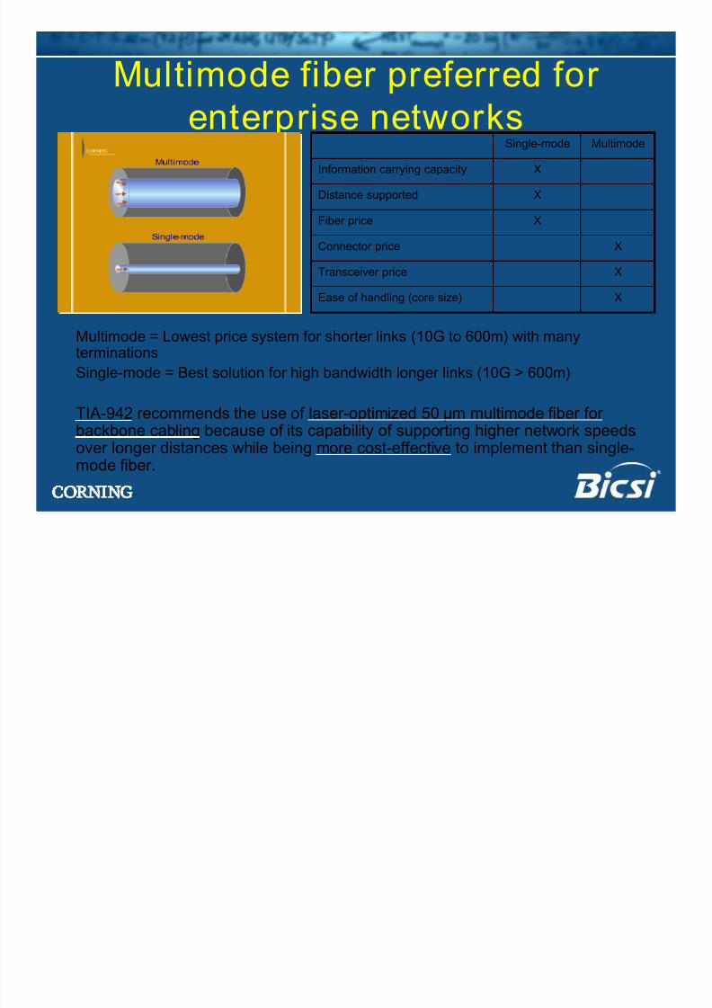
– Benefits of multimode fiber (versus single-mode fiber
and copper)
• Next generation multimode fibers and standards
– OM4 and next generation speeds (16 Gb/s, 40 Gb/s
and 100 Gb/s)
– Bend-insensitive multimode fiber
8/13/2019 Why Cable Bends
http://slidepdf.com/reader/full/why-cable-bends 3/34
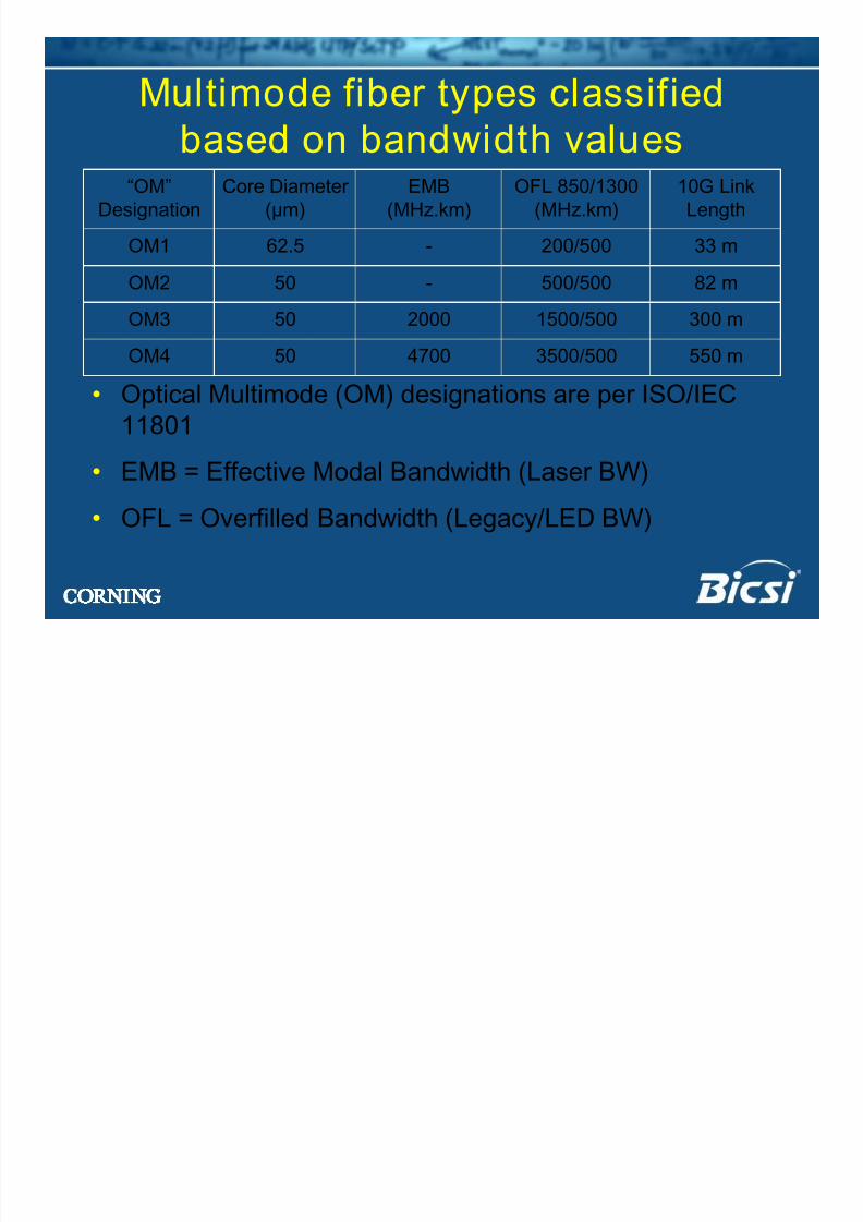
Multimode fiber types classifiedbased on bandwidth values
300 m1500/500200050OM3
50
50
62.5
Core Diameter
(µm)
550 m3500/5004700OM4
82 m500/500-OM2
33 m200/500-OM1
10G Link
Length
OFL 850/1300
(MHz.km)
EMB
(MHz.km)
“OM”
Designation
• Optical Multimode (OM) designations are per ISO/IEC
11801
• EMB = Effective Modal Bandwidth (Laser BW)
• OFL = Overfilled Bandwidth (Legacy/LED BW)
8/13/2019 Why Cable Bends
http://slidepdf.com/reader/full/why-cable-bends 4/34
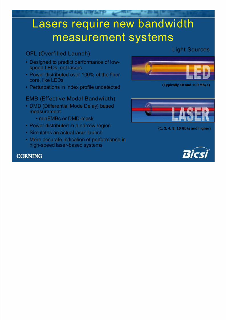
Lasers require new bandwidthmeasurement systems
OFL (Overfil led Launch)
• Designed to predict performance of low-speed LEDs, not lasers
• Power distributed over 100% of the fibercore, like LEDs
• Perturbations in index profile undetected
EMB (Effective Modal Bandwidth)
• DMD (Differential Mode Delay) basedmeasurement
• minEMBc or DMD-mask
• Power distributed in a narrow region
• Simulates an actual laser launch
• More accurate indication of performance inhigh-speed laser-based systems
Light Sources
(Typically 10 and 100 Mb/s)
(1, 2, 4, 8, 10 Gb/s and higher)
8/13/2019 Why Cable Bends
http://slidepdf.com/reader/full/why-cable-bends 5/34
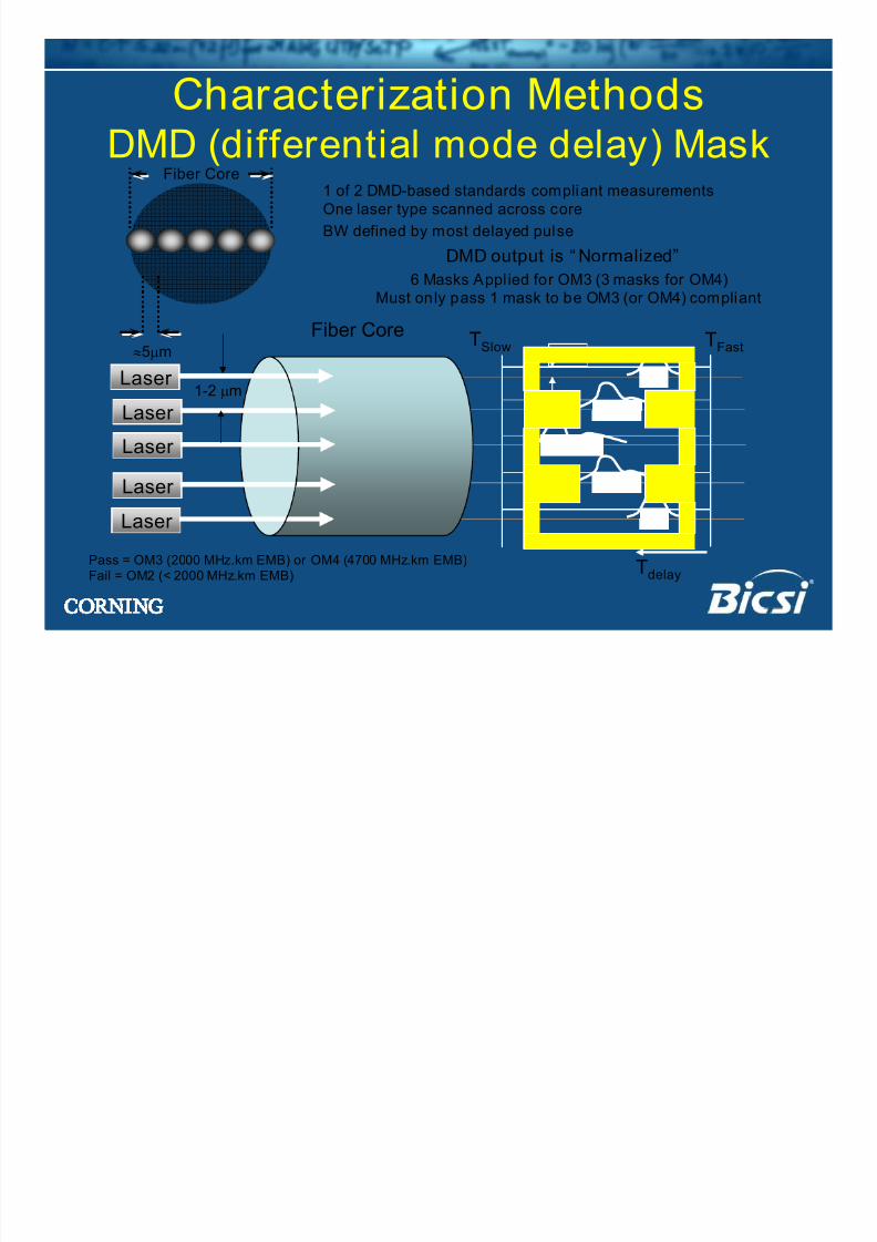
Tdelay
Fiber Core
Laser
Laser
Laser
Fiber Core
≈5µm
Laser
TSlow
TFast
1 of 2 DMD-based standards compliant measurementsOne laser type scanned across core
BW defined by most delayed pulse
Laser
6 Masks Applied for OM3 (3 masks for OM4)Must only pass 1 mask to be OM3 (or OM4) compliant
1-2 µm
25%
DMD output is “ Normalized”
Pass = OM3 (2000 MHz.km EMB) or OM4 (4700 MHz.km EMB)Fail = OM2 (< 2000 MHz.km EMB)
Characterization MethodsDMD (differential mode delay) Mask
8/13/2019 Why Cable Bends
http://slidepdf.com/reader/full/why-cable-bends 6/34
T delay
Fiber Core
Fiber Core
≈5µm
TSlowTFast
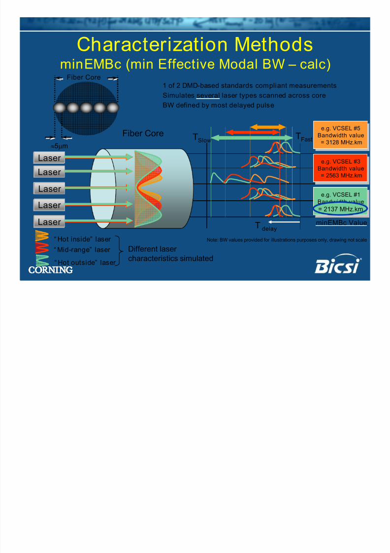
1 of 2 DMD-based standards compliant measurements
Simulates several laser types scanned across core
BW defined by most delayed pulse
Different laser
characteristics simulated“ Hot outside” laser
Laser
“ Mid-range” laser
“ Hot inside” laser
Laser
Laser
Laser Laser
Laser Laser
Laser
Laser Laser
Laser Laser
Laser
Laser Laser
e.g. VCSEL #5Bandwidth value= 3128 MHz.km
e.g. VCSEL #5Bandwidth value= 3128 MHz.km
e.g. VCSEL #3Bandwidth value= 2563 MHz.km
e.g. VCSEL #3Bandwidth value= 2563 MHz.km
e.g. VCSEL #1Bandwidth value
= 2137 MHz.km
e.g. VCSEL #1Bandwidth value
= 2137 MHz.km= 2137 MHz.km
minEMBc Value
Note: BW values provided for illustrations purposes only, drawing not scale
Characterization MethodsminEMBc (min Effective Modal BW – calc)
8/13/2019 Why Cable Bends
http://slidepdf.com/reader/full/why-cable-bends 7/34
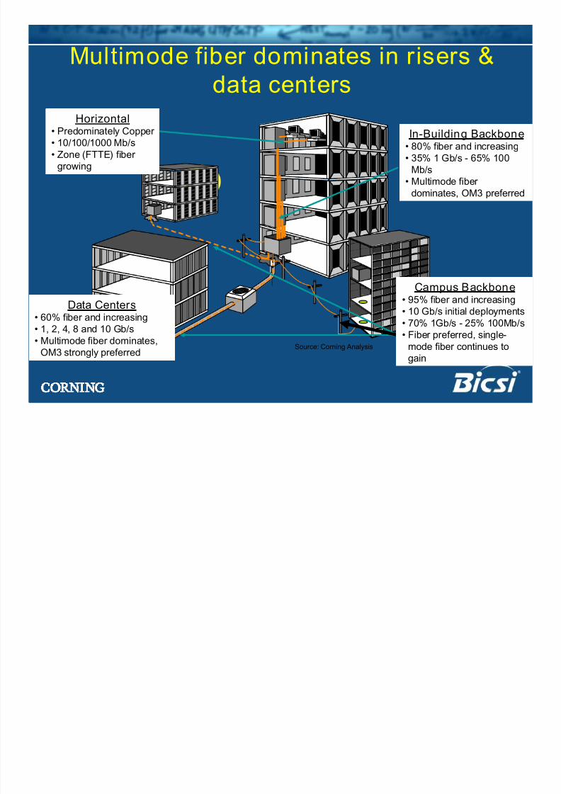
In-Building Backbone
• 80% fiber and increasing• 35% 1 Gb/s - 65% 100
Mb/s
• Multimode fiber
dominates, OM3 preferred
Campus Backbone
• 95% fiber and increasing• 10 Gb/s initial deployments
• 70% 1Gb/s - 25% 100Mb/s
• Fiber preferred, single-
mode fiber continues to
gain
Data Centers• 60% fiber and increasing
• 1, 2, 4, 8 and 10 Gb/s
• Multimode fiber dominates,
OM3 strongly preferred
Horizontal• Predominately Copper
• 10/100/1000 Mb/s
• Zone (FTTE) fibergrowing
Multimode fiber dominates in risers &
data centers
Source: Corning Analysis
8/13/2019 Why Cable Bends
http://slidepdf.com/reader/full/why-cable-bends 8/34
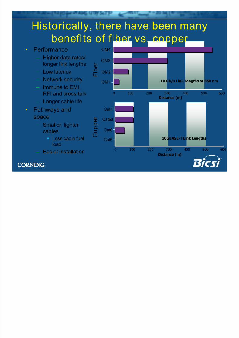
Historically, there have been manybenefits of fiber vs. copper
• Performance
– Higher data rates/
longer link lengths – Low latency
– Network security
– Immune to EMI,
RFI and cross-talk – Longer cable life
• Pathways and
space
– Smaller, lighter
cables
Less cable fuel
load
– Easier installation 0 100 200 300 400 500 600
Cat6a
Cat7
Distance (m)
Cat5 10GBASE-T Link Lengths
Cat6
C o p
p e r
0 100 200 300 400 500 600
OM3
OM4
Distance (m)
OM1 10 Gb/s Link Lengths at 850 nm
OM2 F i b e r
8/13/2019 Why Cable Bends
http://slidepdf.com/reader/full/why-cable-bends 9/34
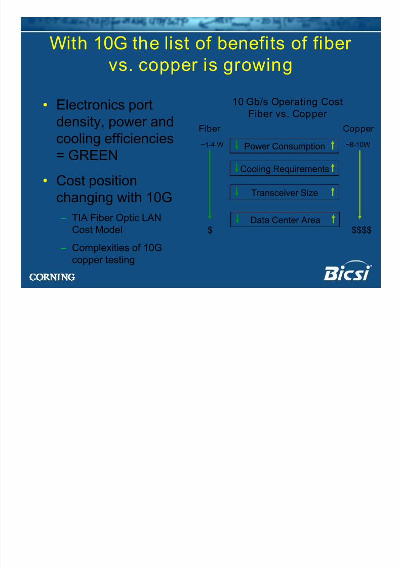
With 10G the list of benefits of fibervs. copper is growing
• Electronics portdensity, power and
cooling efficiencies
= GREEN• Cost position
changing with 10G
– TIA Fiber Optic LANCost Model
– Complexities of 10G
copper testing
10 Gb/s Operating CostFiber vs. Copper
Fiber Copper
Power Consumption
Cooling Requirements
Transceiver Size
Data Center Area
~1-4 W
$
~8-10W
$$$$
8/13/2019 Why Cable Bends
http://slidepdf.com/reader/full/why-cable-bends 10/34
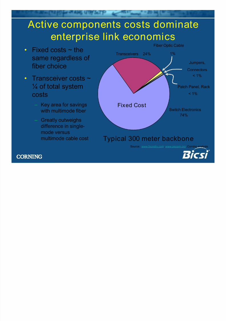
Active components costs dominateenterprise link economics
Typical 300 meter backbone
• Fixed costs ~ the
same regardless offiber choice
• Transceiver costs ~
¼ of total system
costs
– Key area for savings
with multimode fiber
– Greatly outweighsdifference in single-
mode versus
multimode cable cost
Jumpers,
Connectors
< 1%
Fiber Optic Cable
1%
Patch Panel, Rack
< 1%
Transceivers 24%
Switch Electronics
74%
Fixed Cost
Source: www.foundry.com, www.peppm.org, Corning analysis
8/13/2019 Why Cable Bends
http://slidepdf.com/reader/full/why-cable-bends 11/34
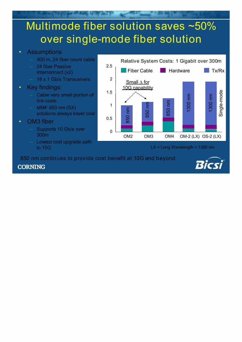
Multimode fiber solution saves ~50%over single-mode fiber solution
• Assumptions
– 300 m, 24 fiber count cable
– 24 fiber PassiveInterconnect (x2)
– 18 x 1 Gb/s Transceivers
• Key findings:
– Cable very small portion of
link costs
– MMF 850 nm (SX)
solutions always lower cost
• OM3 fiber
– Supports 10 Gb/s over300m
– Lowest cost upgrade path
to 10G
0
0.5
1
1.5
2
2.5
OM2 OM3 OM-2 (LX) OS-2 (LX)
Relative System Costs: 1 Gigabit over 300m
Fiber Cable Hardware Tx/Rx
1 3 0 0 n m
1 3 0 0 n m
8 5 0 n m
8 5 0 n m
OM4
8 5 0 n m
S i n g l e - m o d e
Small ∆ for
10G capability
LX = Long Wavelength = 1300 nm
850 nm continues to provide cost benefit at 10G and beyond
8/13/2019 Why Cable Bends
http://slidepdf.com/reader/full/why-cable-bends 12/34
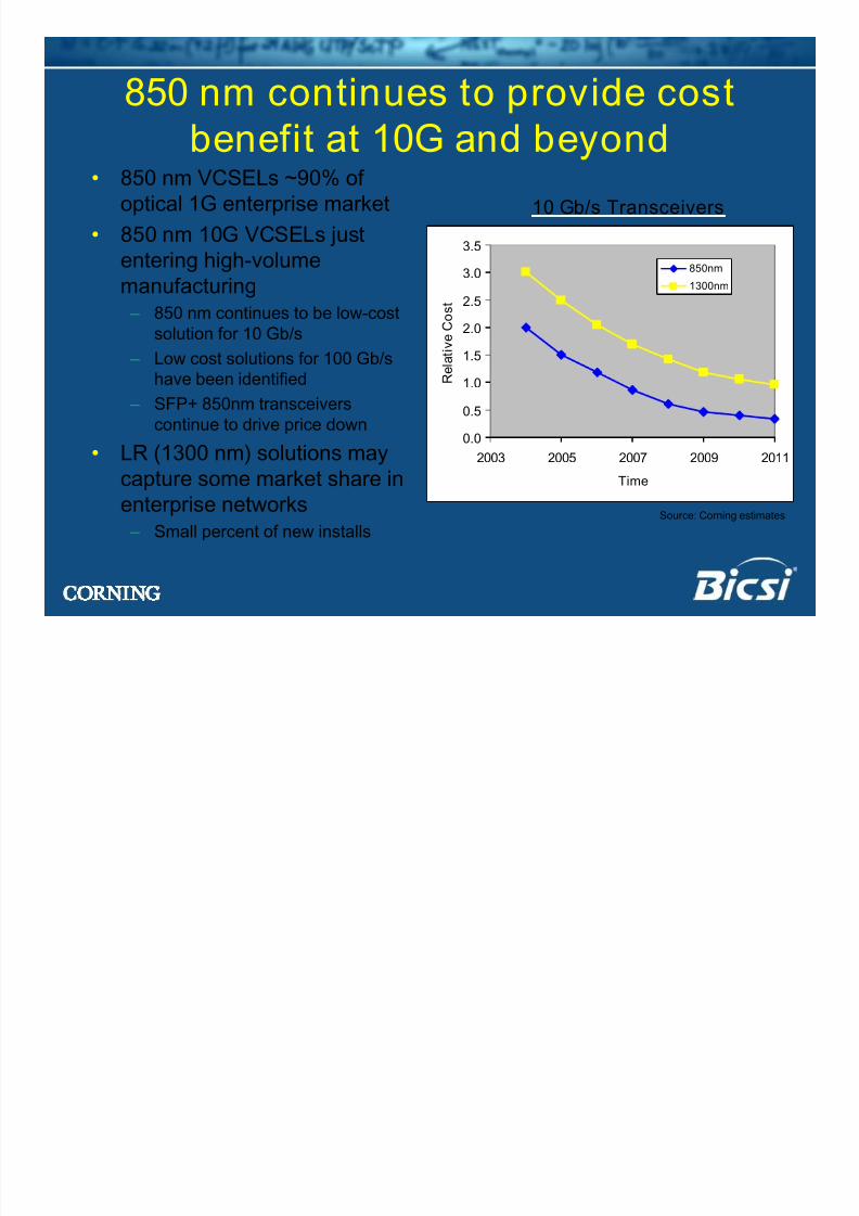
850 nm continues to provide costbenefit at 10G and beyond
• 850 nm VCSELs ~90% of
optical 1G enterprise market
• 850 nm 10G VCSELs justentering high-volume
manufacturing
– 850 nm continues to be low-cost
solution for 10 Gb/s
– Low cost solutions for 100 Gb/s
have been identified
– SFP+ 850nm transceivers
continue to drive price down
• LR (1300 nm) solutions maycapture some market share in
enterprise networks
– Small percent of new installs
10 Gb/s Transceivers
Source: Corning estimates
0.0
0.5
1.0
1.5
2.0
2.5
3.0
3.5
2003 2005 2007 2009 2011
Time
R e l a t i v
e C o s t
850nm
1300nm
8/13/2019 Why Cable Bends
http://slidepdf.com/reader/full/why-cable-bends 13/34
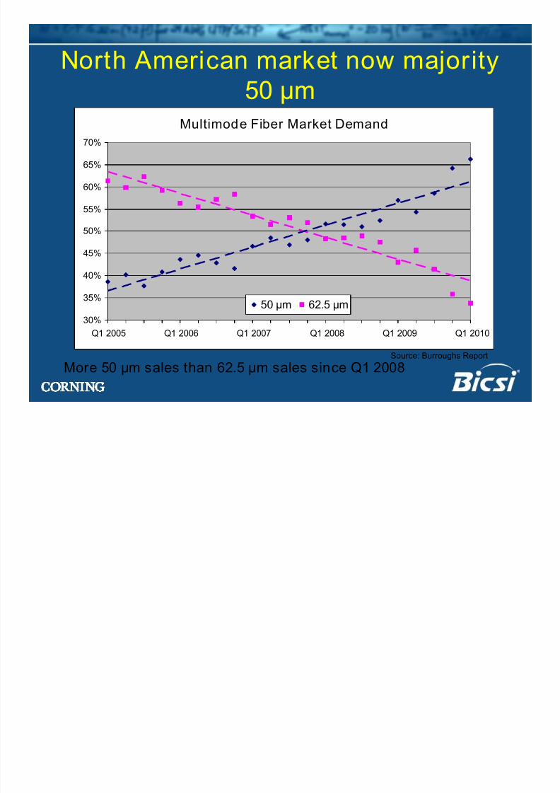
North American market now majority50 µm
Source: Burroughs Report
More 50 µm sales than 62.5 µm sales since Q1 2008
Multimode Fiber Market Demand
30%
35%
40%
45%
50%
55%
60%
65%
70%
Q1 2005 Q1 2006 Q1 2007 Q1 2008 Q1 2009 Q1 2010
50 µm 62.5 µm
8/13/2019 Why Cable Bends
http://slidepdf.com/reader/full/why-cable-bends 14/34
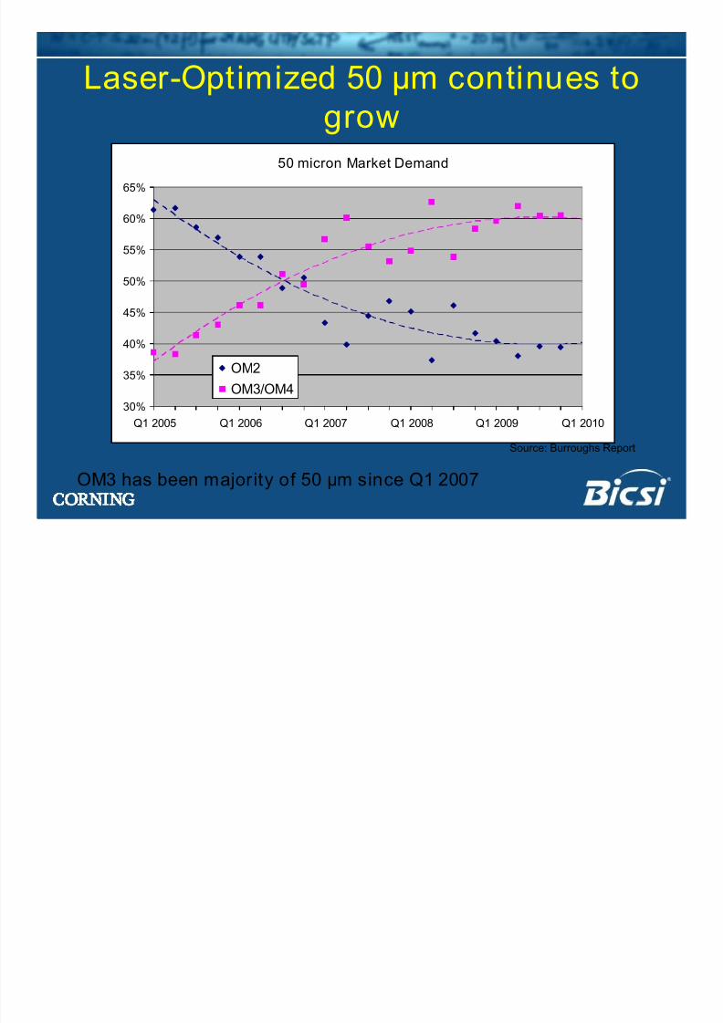
Laser-Optimized 50 µm continues togrow
Source: Burroughs Report
OM3 has been majority of 50 µm since Q1 2007
50 micron Market Demand
30%
35%
40%
45%
50%
55%
60%
65%
Q1 2005 Q1 2006 Q1 2007 Q1 2008 Q1 2009 Q1 2010
OM2
OM3/OM4
8/13/2019 Why Cable Bends
http://slidepdf.com/reader/full/why-cable-bends 15/34
8/13/2019 Why Cable Bends
http://slidepdf.com/reader/full/why-cable-bends 16/34
Part II• Next generation multimode fibers and
standards – OM4 and next generation speeds (16 Gb/s, 40 Gb/s
and 100 Gb/s)
– Bend-insensitive multimode fiber
8/13/2019 Why Cable Bends
http://slidepdf.com/reader/full/why-cable-bends 17/34
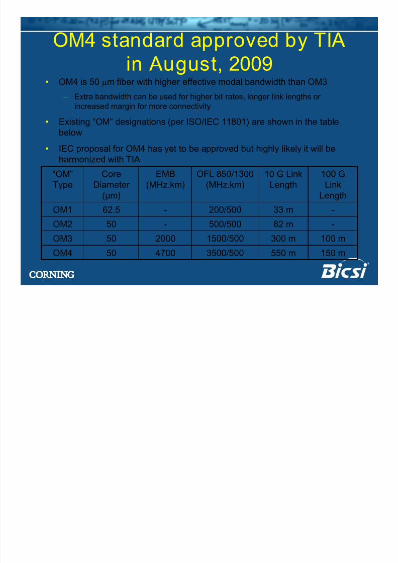
OM4 standard approved by TIAin August, 2009
• OM4 is 50 µm fiber with higher effective modal bandwidth than OM3
– Extra bandwidth can be used for higher bit rates, longer link lengths or
increased margin for more connectivity
• Existing “OM” designations (per ISO/IEC 11801) are shown in the table
below
• IEC proposal for OM4 has yet to be approved but highly likely it will be
harmonized with TIA
550 m
300 m
82 m
33 m
10 G Link
Length
100 m1500/500200050OM3
50
50
62.5
Core
Diameter
(µm)
150 m3500/5004700OM4
-500/500-OM2
-200/500-OM1
100 G
Link
Length
OFL 850/1300
(MHz.km)
EMB
(MHz.km)
“OM”
Type
8/13/2019 Why Cable Bends
http://slidepdf.com/reader/full/why-cable-bends 18/34
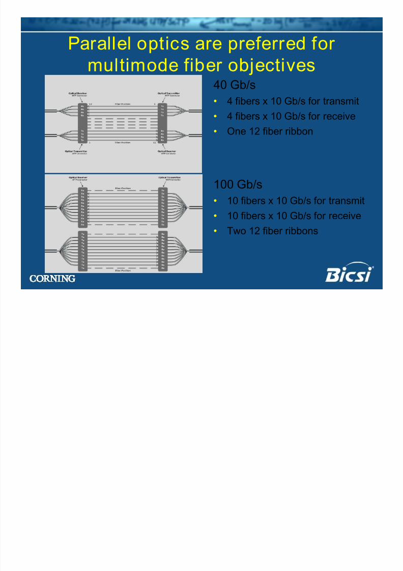
Parallel optics are preferred formultimode fiber objectives
40 Gb/s
• 4 fibers x 10 Gb/s for transmit
• 4 fibers x 10 Gb/s for receive
• One 12 fiber ribbon
100 Gb/s
• 10 fibers x 10 Gb/s for transmit
• 10 fibers x 10 Gb/s for receive• Two 12 fiber ribbons
8/13/2019 Why Cable Bends
http://slidepdf.com/reader/full/why-cable-bends 19/34
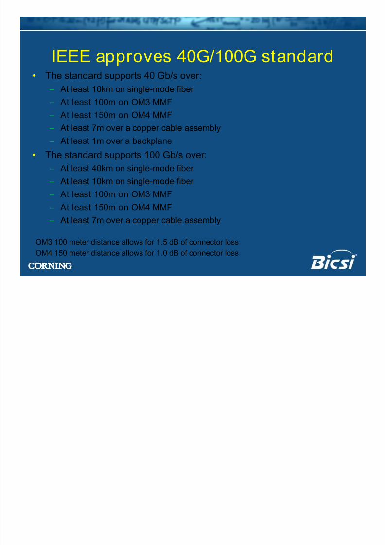
• The standard supports 40 Gb/s over:
– At least 10km on single-mode fiber
– At least 100m on OM3 MMF – At least 150m on OM4 MMF
– At least 7m over a copper cable assembly
– At least 1m over a backplane
• The standard supports 100 Gb/s over: – At least 40km on single-mode fiber
– At least 10km on single-mode fiber
– At least 100m on OM3 MMF
– At least 150m on OM4 MMF – At least 7m over a copper cable assembly
IEEE approves 40G/100G standard
OM3 100 meter distance allows for 1.5 dB of connector loss
OM4 150 meter distance allows for 1.0 dB of connector loss
8/13/2019 Why Cable Bends
http://slidepdf.com/reader/full/why-cable-bends 20/34
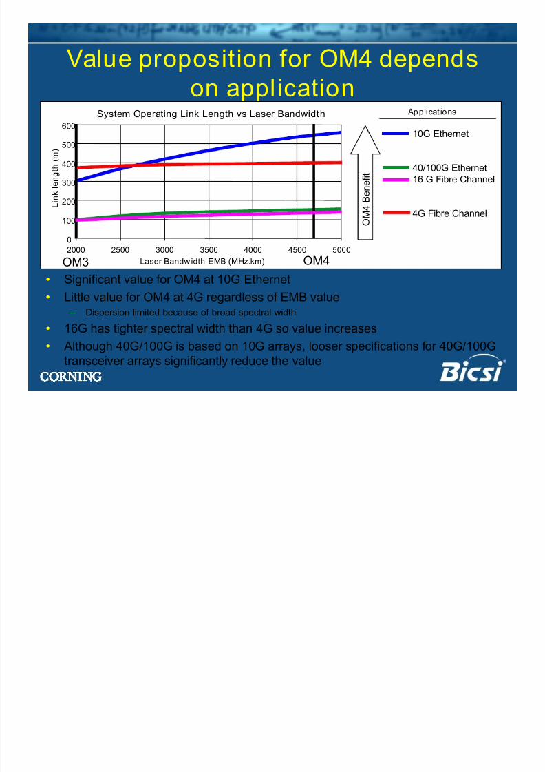
Value proposition for OM4 dependson application
• Significant value for OM4 at 10G Ethernet
• Little value for OM4 at 4G regardless of EMB value – Dispersion limited because of broad spectral width
• 16G has tighter spectral width than 4G so value increases
• Although 40G/100G is based on 10G arrays, looser specifications for 40G/100G
transceiver arrays significantly reduce the value
10G Ethernet
40/100G Ethernet
16 G Fibre Channel
4G Fibre Channel
System Operating Link Length vs Laser Bandwidth
0
100
200
300
400
500
600
2000 2500 3000 3500 4000 4500 5000
Laser Bandwidth EMB (MHz.km)
L i n k l e n g t h ( m )
O
M 4 B e n e f i t
Applicat ions
OM3 OM4
8/13/2019 Why Cable Bends
http://slidepdf.com/reader/full/why-cable-bends 21/34
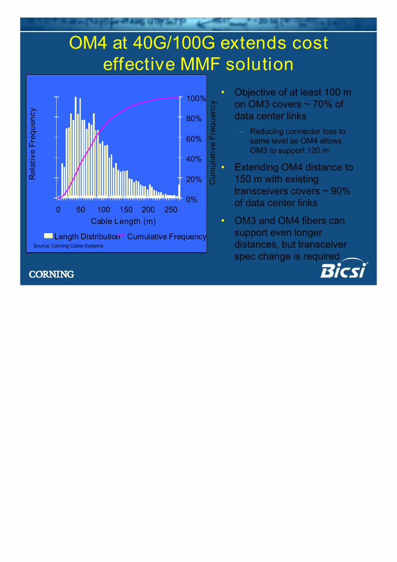
OM4 at 40G/100G extends costeffective MMF solution
• Objective of at least 100 m
on OM3 covers ~ 70% ofdata center links
– Reducing connector loss to
same level as OM4 allows
OM3 to support 120 m
• Extending OM4 distance to
150 m with existing
transceivers covers ~ 90%
of data center links
• OM3 and OM4 fibers can
support even longer
distances, but transceiver
spec change is required
Source: Corning Cable Systems
0 50 100 150 200 250
Cable Length (m)
R e l a t i v e F r e q u e n c y
0%
20%
40%
60%
80%
100%
C u m u l
a t i v e F r e q u e n c y
Length Distribution Cumulative Frequency
8/13/2019 Why Cable Bends
http://slidepdf.com/reader/full/why-cable-bends 22/34
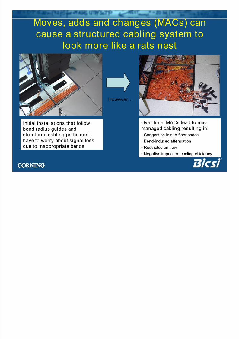
Over time, MACs lead to mis-
managed cabling resulting in:• Congestion in sub-floor space
• Bend-induced attenuation
• Restricted air flow
• Negative impact on cooling efficiency
Moves, adds and changes (MACs) can
cause a structured cabling system tolook more like a rats nest
Initial installations that follow
bend radius guides andstructured cabling paths don’thave to worry about signal lossdue to inappropriate bends
However…
8/13/2019 Why Cable Bends
http://slidepdf.com/reader/full/why-cable-bends 23/34
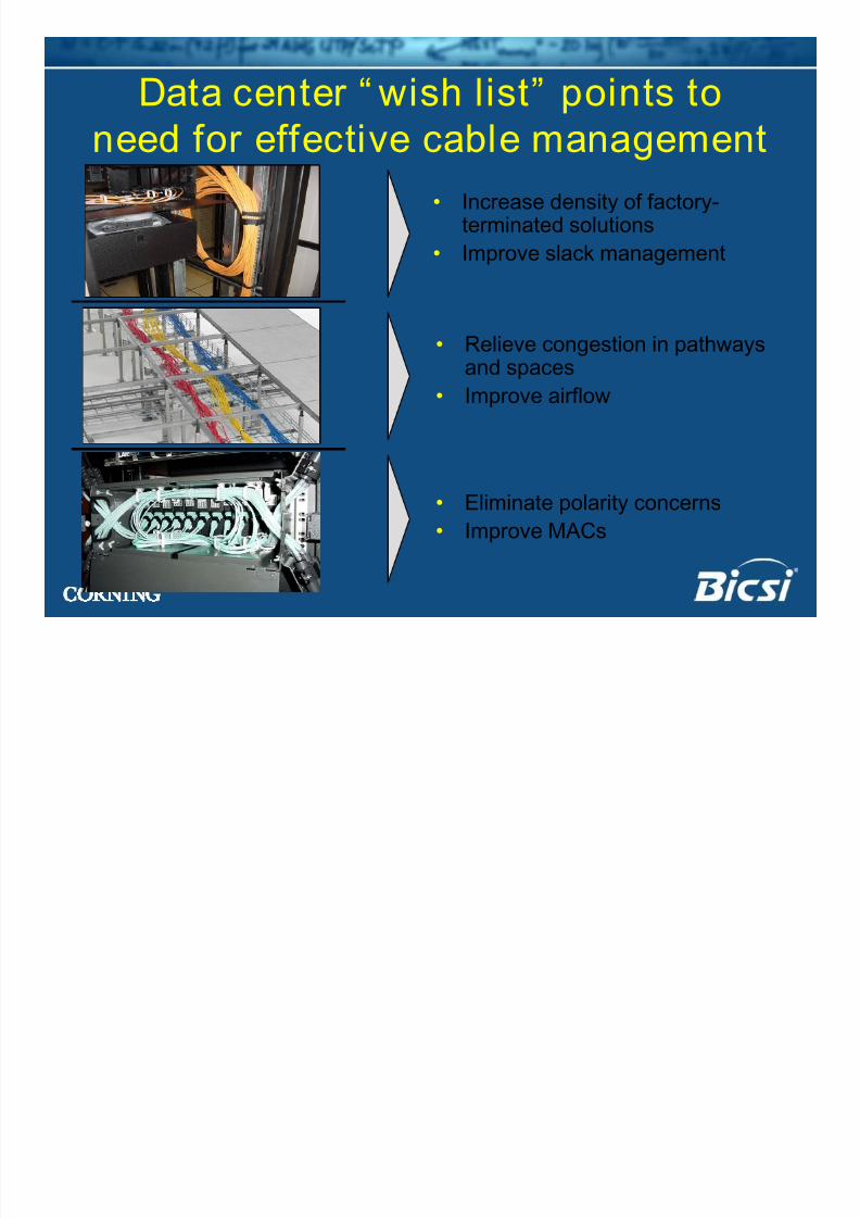
Data center “ wish list” points toneed for effective cable management
• Increase density of factory-
terminated solutions• Improve slack management
• Relieve congestion in pathwaysand spaces
• Improve airflow
• Eliminate polarity concerns
• Improve MACs
8/13/2019 Why Cable Bends
http://slidepdf.com/reader/full/why-cable-bends 24/34
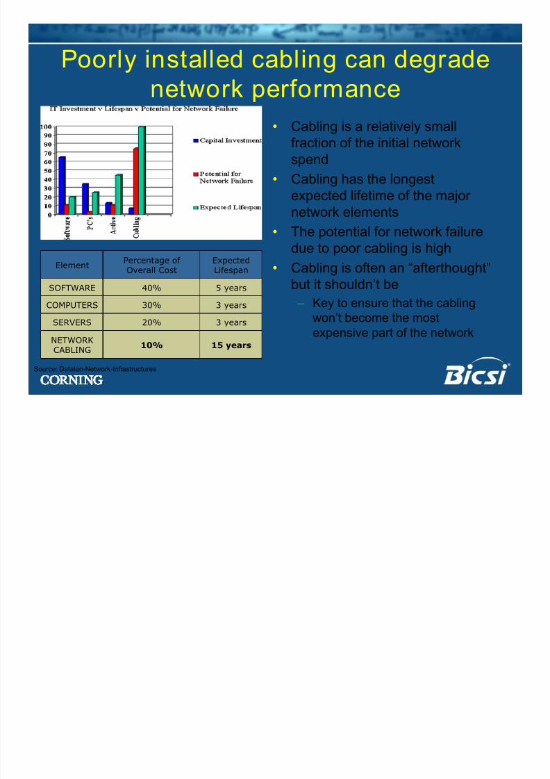
15 years10%NETWORKCABLING
3 years20%SERVERS
3 years30%COMPUTERS
5 years40%SOFTWARE
ExpectedLifespan
Percentage ofOverall Cost
Element
Source: Datalan-Network-Infrastructures
Poorly installed cabling can degradenetwork performance
• Cabling is a relatively small
fraction of the initial network
spend
• Cabling has the longest
expected lifetime of the major
network elements
• The potential for network failure
due to poor cabling is high
• Cabling is often an “afterthought”
but it shouldn’t be
– Key to ensure that the cablingwon’t become the most
expensive part of the network
8/13/2019 Why Cable Bends
http://slidepdf.com/reader/full/why-cable-bends 25/34
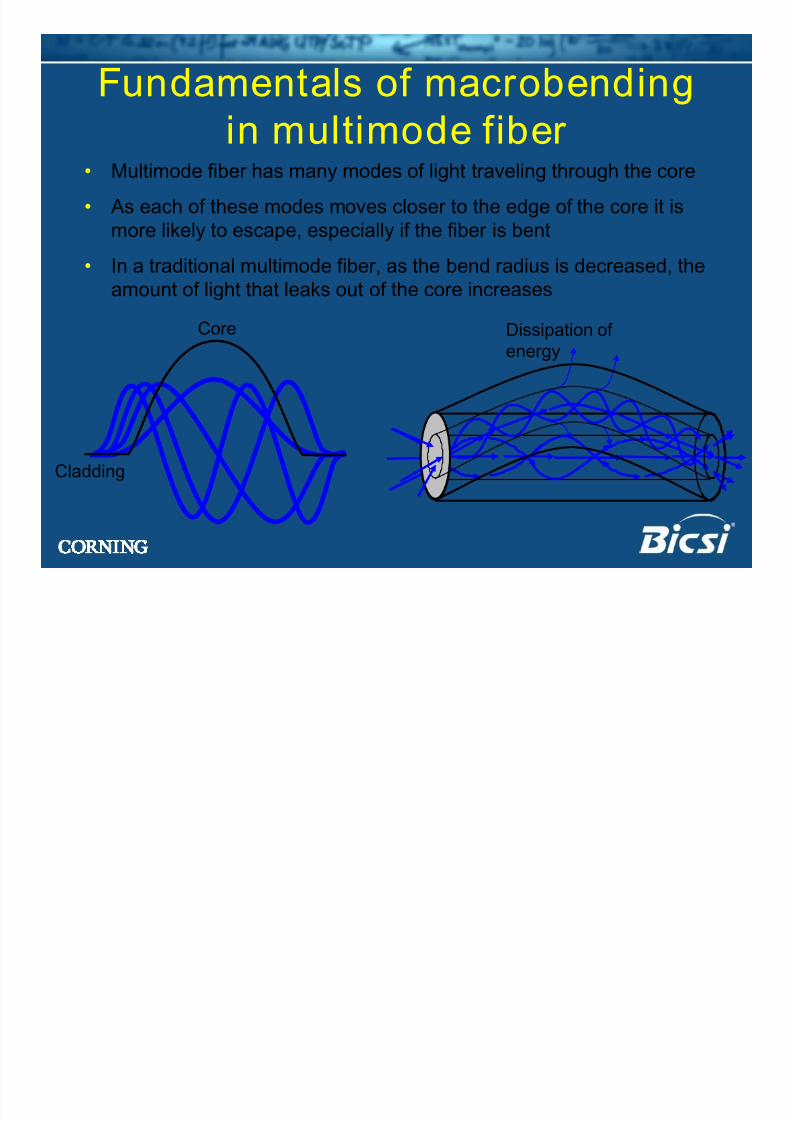
Fundamentals of macrobendingin multimode fiber
• Multimode fiber has many modes of light traveling through the core
• As each of these modes moves closer to the edge of the core it is
more likely to escape, especially if the fiber is bent
• In a traditional multimode fiber, as the bend radius is decreased, the
amount of light that leaks out of the core increases
Dissipation ofenergy
Core
Cladding
8/13/2019 Why Cable Bends
http://slidepdf.com/reader/full/why-cable-bends 26/34
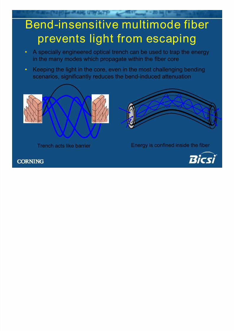
Bend-insensitive multimode fiber prevents light from escaping
• A specially engineered optical trench can be used to trap the energy
in the many modes which propagate within the fiber core
• Keeping the light in the core, even in the most challenging bending
scenarios, significantly reduces the bend-induced attenuation
Energy is confined inside the fiber Trench acts like barrier
8/13/2019 Why Cable Bends
http://slidepdf.com/reader/full/why-cable-bends 27/34
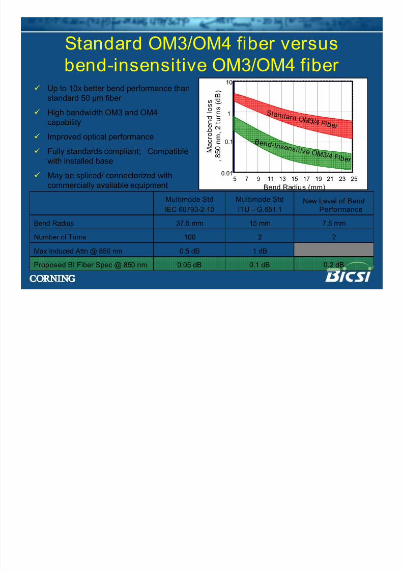
Standard OM3/OM4 fiber versusbend-insensitive OM3/OM4 fiber
Up to 10x better bend performance than
standard 50 µm fiber
High bandwidth OM3 and OM4capability
Improved optical performance
Fully standards compliant; Compatible
with installed base
May be spliced/ connectorized with
commercially available equipment
0.01
0.1
1
10
5 7 9 11 13 15 17 19 21 23 25
Bend Radius (mm)
M a c r o b e n d l o s s
, 8 5 0 n m ,
2 t u r n s ( d B )
B e nd - I ns e ns i t i v e O M 3 / 4 F i b e r
S t and ar d O M 3 / 4 F i b e r
1 dB0.5 dBMax Induced Attn @ 850 nm
0.05 dB
100
37.5 mm
Multimode Std
IEC 60793-2-10
Proposed BI Fiber Spec @ 850 nm
Number of Turns
Bend Radius
0.2 dB
2
7.5 mm
New Level of BendPerformance
0.1 dB
2
15 mm
Multimode Std
ITU – G.651.1
8/13/2019 Why Cable Bends
http://slidepdf.com/reader/full/why-cable-bends 28/34
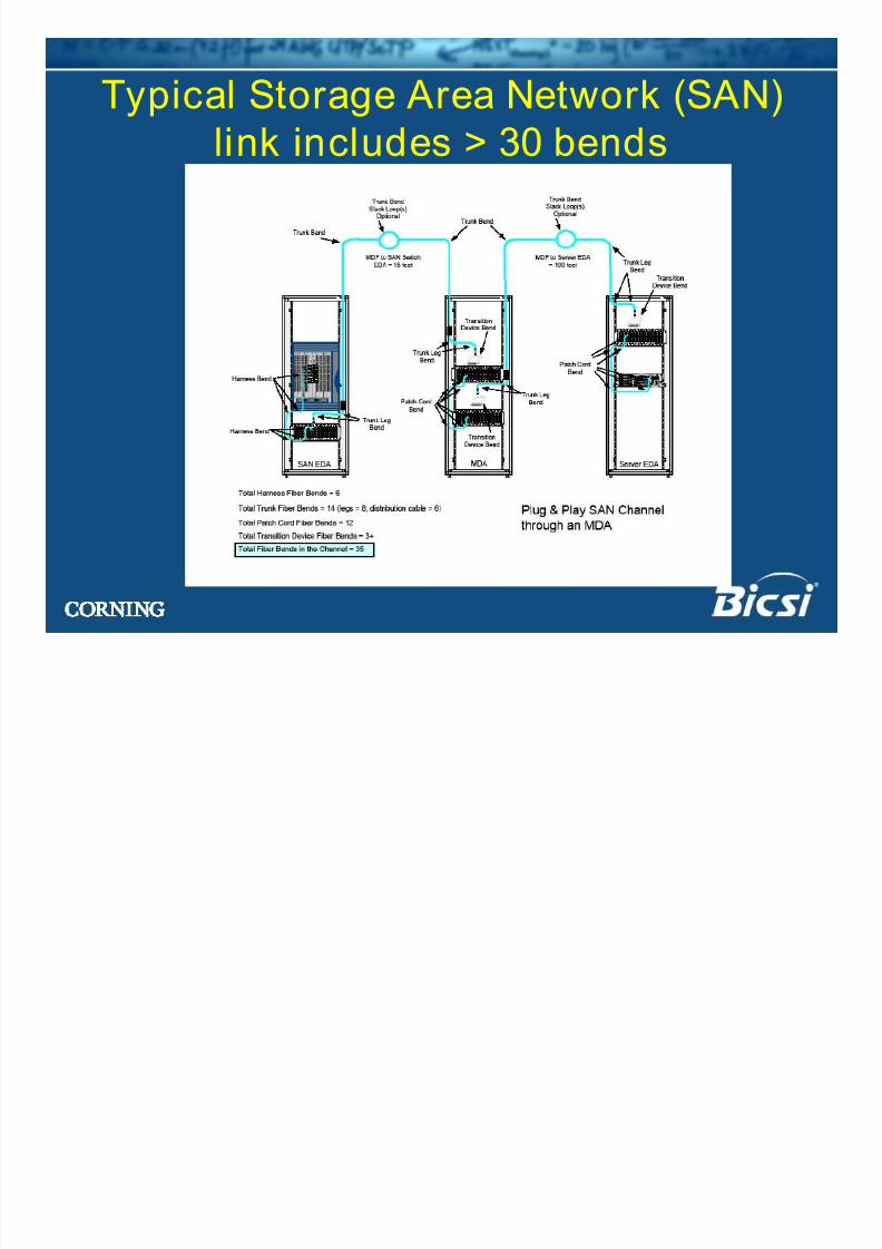
Typical Storage Area Network (SAN)link includes > 30 bends
8/13/2019 Why Cable Bends
http://slidepdf.com/reader/full/why-cable-bends 29/34
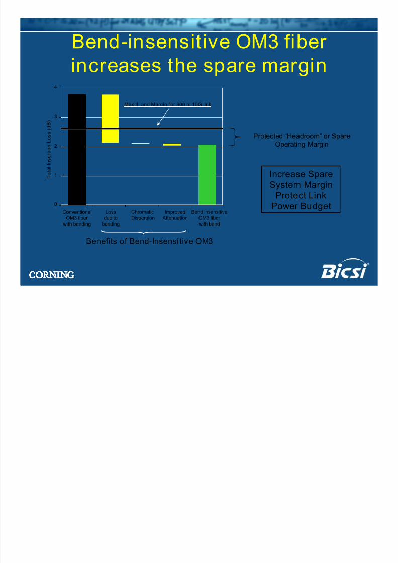
Bend-insensitive OM3 fiberincreases the spare margin
Protected “Headroom” or Spare
Operating Margin
0
1
2
3
4
Conventional
OM3 fiber with bending
Loss
due tobending
Chromatic
Dispersion
Improved
Attenuation
Bend insensitive
OM3 fiber with bend
T o t a l I n
s e r t i o n L o s s ( d B )
Max IL and Margin for 300 m 10G link
Increase Spare
System Margin
Protect Link
Power Budget
Benefits of Bend-Insensi tive OM3
8/13/2019 Why Cable Bends
http://slidepdf.com/reader/full/why-cable-bends 30/34
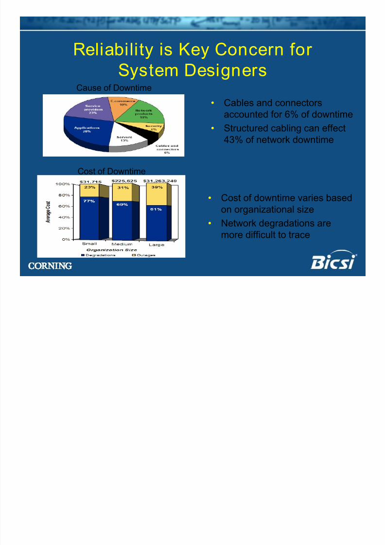
Reliability is Key Concern forSystem DesignersCause of Downtime
Cost of Downtime
• Cables and connectorsaccounted for 6% of downtime
• Structured cabling can effect
43% of network downtime
• Cost of downtime varies based
on organizational size• Network degradations are
more difficult to trace
8/13/2019 Why Cable Bends
http://slidepdf.com/reader/full/why-cable-bends 31/34
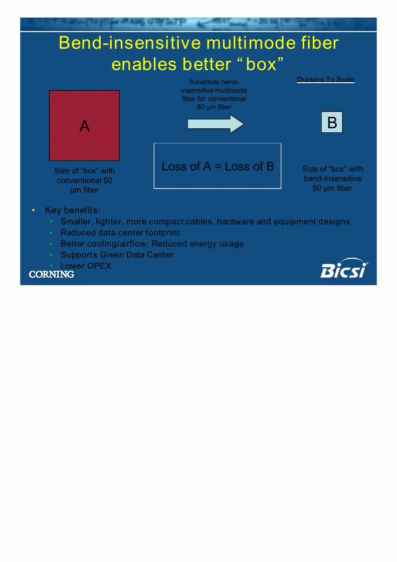
Bend-insensitive multimode fiber
enables better “ box”
• Key benefits:
• Smaller, lighter, more compact cables, hardware and equipment designs
• Reduced data center footprint
• Better cooling/airflow; Reduced energy usage
• Supports Green Data Center
• Lower OPEX
A B
Size of “box” with
conventional 50
µm fiber
Size of “box” with
bend-insensitive
50 µm fiber
Loss of A = Loss of B
Drawing To ScaleSubstitute bend-
insensitive multimode
fiber for conventional
50 µm fiber
8/13/2019 Why Cable Bends
http://slidepdf.com/reader/full/why-cable-bends 32/34
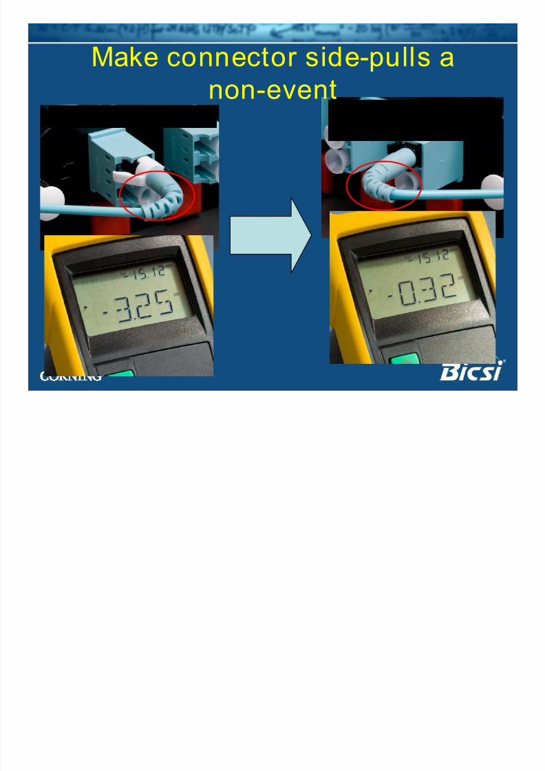
Make connector side-pulls anon-event
Standard 50 µm fiber Bend-insensitive 50µm fiber
8/13/2019 Why Cable Bends
http://slidepdf.com/reader/full/why-cable-bends 33/34
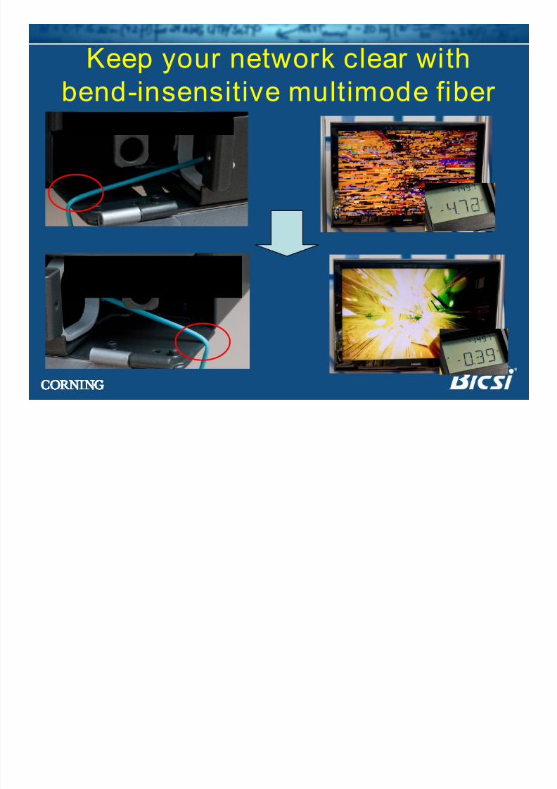
Keep your network clear withbend-insensitive multimode fiber
Standard 50 µm fiber
Bend-insensitive 50µm fiber
8/13/2019 Why Cable Bends
http://slidepdf.com/reader/full/why-cable-bends 34/34
Summary• Multimode fiber remains the most cost-effective choice
for enterprise networks
• Bend-insensitive multimode fibers can help solve key
concerns of enterprise network operators
• OM4 fibers are now standardized and provide a path for
extended distances for next generation speeds
• Next generation standards will use OM3 and OM4 fibers
to provide low cost future-proof solutions for enterprise
networks