Embed Size (px)
Citation preview
William Stallings Computer Organization and Architecture 8th Edition
Chapter 7 Input/Output
Input/Output Problems • Wide variety of peripherals
—Delivering different amounts of data —At different speeds —In different formats
• All slower than CPU and RAM • Need I/O modules
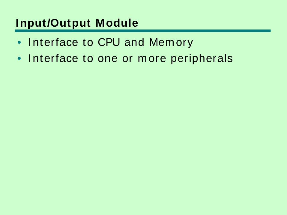
Input/Output Module • Interface to CPU and Memory • Interface to one or more peripherals
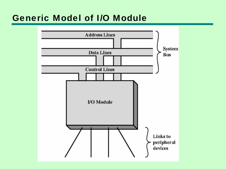
Generic Model of I/O Module
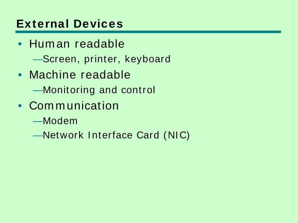
External Devices • Human readable
—Screen, printer, keyboard
• Machine readable —Monitoring and control
• Communication —Modem —Network Interface Card (NIC)
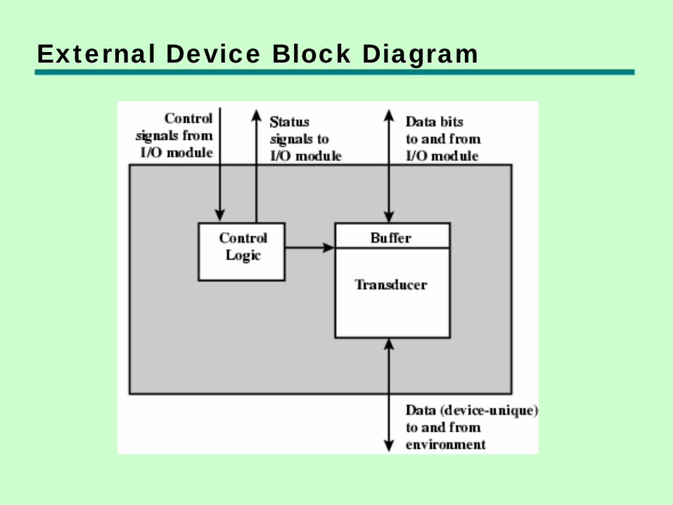
External Device Block Diagram
I/O Module Function • Control & Timing • CPU Communication • Device Communication • Data Buffering • Error Detection
I/O Steps • CPU checks I/O module device status • I/O module returns status • If ready, CPU requests data transfer • I/O module gets data from device • I/O module transfers data to CPU • Variations for output, DMA, etc.
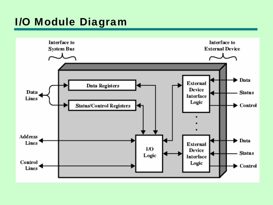
I/O Module Diagram
I/O Module Decisions • Hide or reveal device properties to CPU • Support multiple or single device • Control device functions or leave for CPU • Also O/S decisions
—e.g. Unix treats everything it can as a file
Input Output Techniques • Programmed • Interrupt driven • Direct Memory Access (DMA)
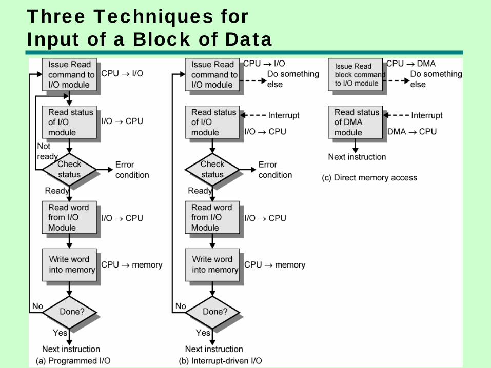
Three Techniques for Input of a Block of Data
Programmed I/O • CPU has direct control over I/O
—Sensing status —Read/write commands —Transferring data
• CPU waits for I/O module to complete operation
• Wastes CPU time
Programmed I/O - detail • CPU requests I/O operation • I/O module performs operation • I/O module sets status bits • CPU checks status bits periodically • I/O module does not inform CPU directly • I/O module does not interrupt CPU • CPU may wait or come back later
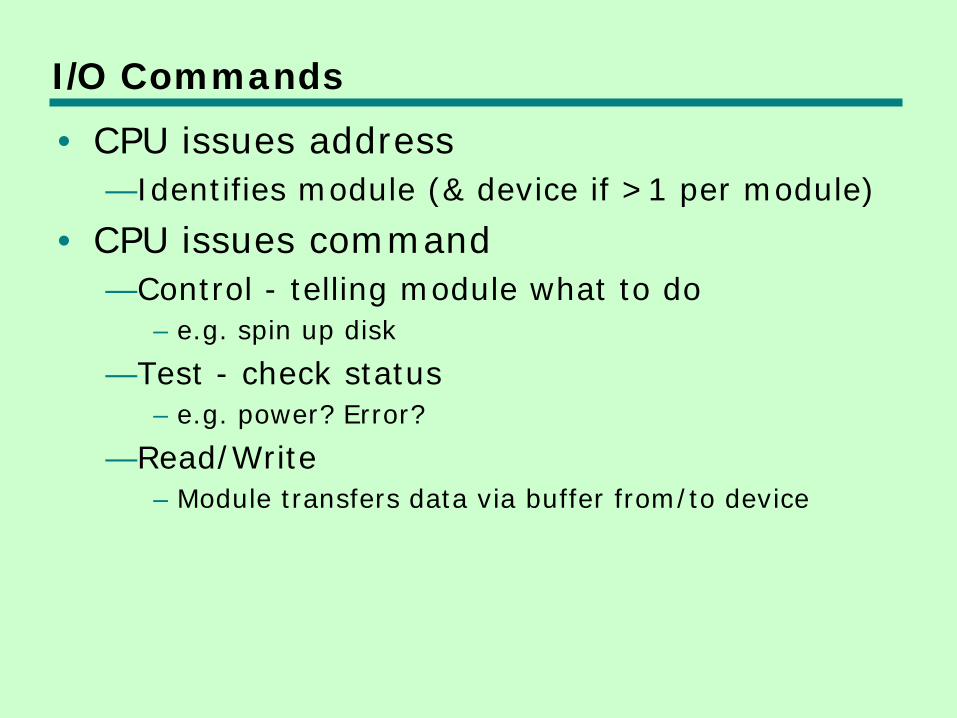
I/O Commands • CPU issues address
—Identifies module (& device if >1 per module)
• CPU issues command —Control - telling module what to do
– e.g. spin up disk
—Test - check status – e.g. power? Error?
—Read/Write – Module transfers data via buffer from/to device
Addressing I/O Devices • Under programmed I/O data transfer is
very like memory access (CPU viewpoint) • Each device given unique identifier • CPU commands contain identifier
(address)
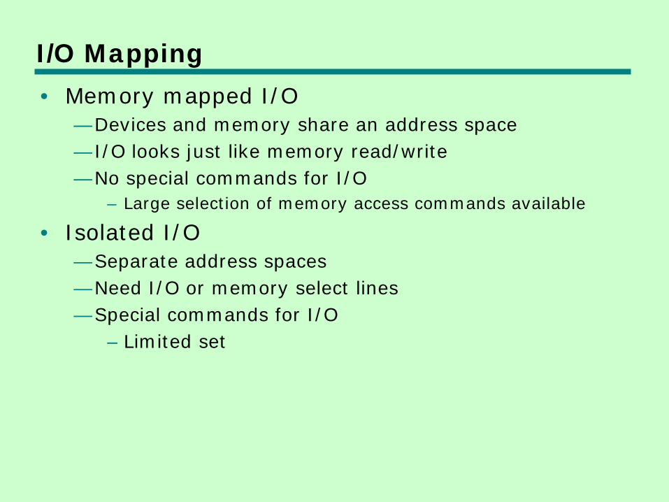
I/O Mapping • Memory mapped I/O
—Devices and memory share an address space —I/O looks just like memory read/write —No special commands for I/O
– Large selection of memory access commands available
• Isolated I/O —Separate address spaces —Need I/O or memory select lines —Special commands for I/O
– Limited set
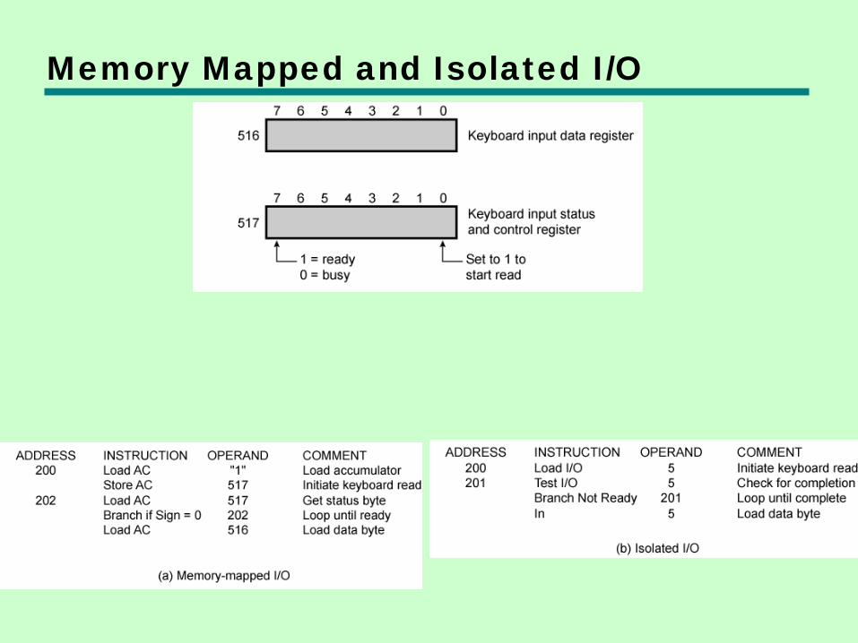
Memory Mapped and Isolated I/O
Interrupt Driven I/O • Overcomes CPU waiting • No repeated CPU checking of device • I/O module interrupts when ready
Interrupt Driven I/O Basic Operation • CPU issues read command • I/O module gets data from peripheral
whilst CPU does other work • I/O module interrupts CPU • CPU requests data • I/O module transfers data
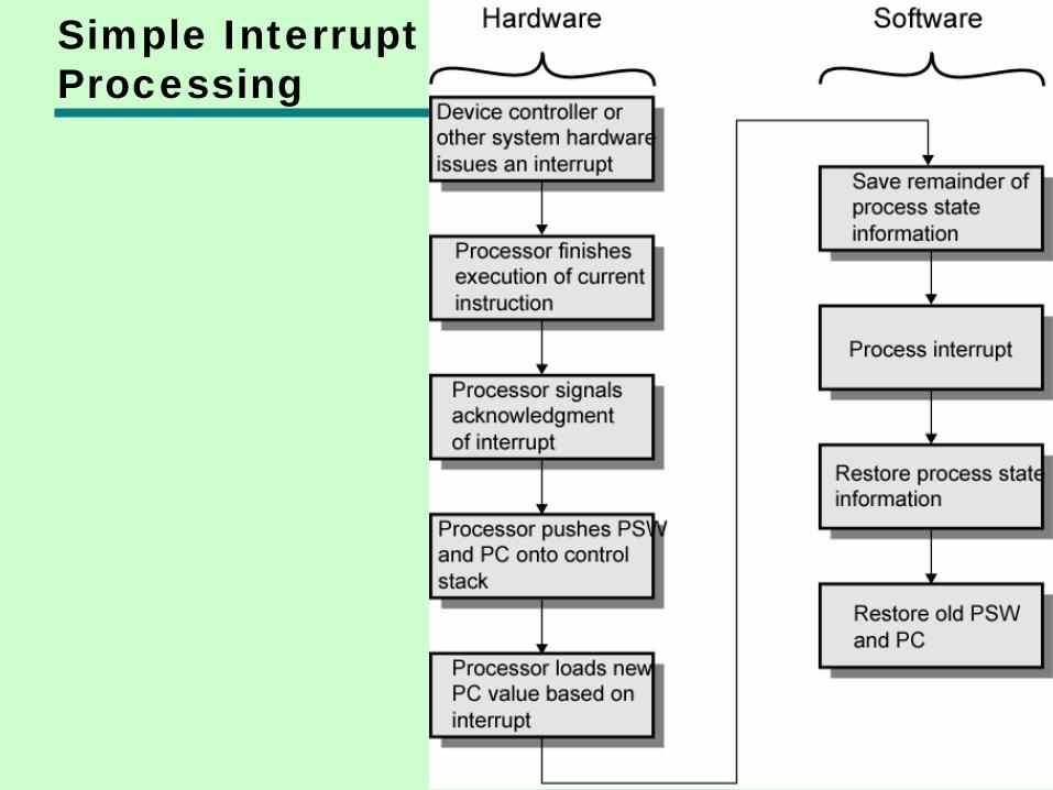
Simple Interrupt Processing
CPU Viewpoint • Issue read command • Do other work • Check for interrupt at end of each
instruction cycle • If interrupted:-
—Save context (registers) —Process interrupt
– Fetch data & store
• See Operating Systems notes
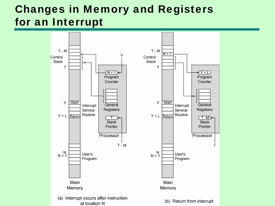
Changes in Memory and Registers for an Interrupt
Design Issues • How do you identify the module issuing
the interrupt? • How do you deal with multiple interrupts?
—i.e. an interrupt handler being interrupted
Identifying Interrupting Module (1) • Different line for each module
—PC —Limits number of devices
• Software poll —CPU asks each module in turn —Slow
Identifying Interrupting Module (2) • Daisy Chain or Hardware poll
—Interrupt Acknowledge sent down a chain —Module responsible places vector on bus —CPU uses vector to identify handler routine
• Bus Master —Module must claim the bus before it can raise
interrupt —e.g. PCI & SCSI
Multiple Interrupts • Each interrupt line has a priority • Higher priority lines can interrupt lower
priority lines • If bus mastering only current master can
interrupt
Example - PC Bus • 80x86 has one interrupt line • 8086 based systems use one 8259A
interrupt controller • 8259A has 8 interrupt lines
Sequence of Events • 8259A accepts interrupts • 8259A determines priority • 8259A signals 8086 (raises INTR line) • CPU Acknowledges • 8259A puts correct vector on data bus • CPU processes interrupt
ISA Bus Interrupt System • ISA bus chains two 8259As together • Link is via interrupt 2 • Gives 15 lines
—16 lines less one for link
• IRQ 9 is used to re-route anything trying to use IRQ 2 —Backwards compatibility
• Incorporated in chip set
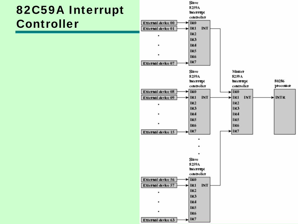
82C59A Interrupt Controller
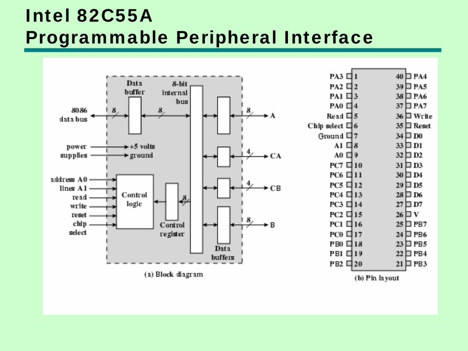
Intel 82C55A Programmable Peripheral Interface
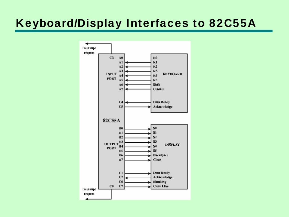
Keyboard/Display Interfaces to 82C55A

Direct Memory Access • Interrupt driven and programmed I/O
require active CPU intervention —Transfer rate is limited —CPU is tied up
• DMA is the answer
DMA Function • Additional Module (hardware) on bus • DMA controller takes over from CPU for
I/O
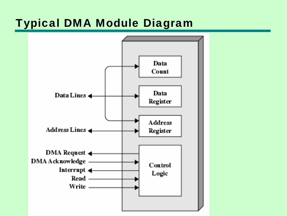
Typical DMA Module Diagram
DMA Operation • CPU tells DMA controller:-
—Read/Write —Device address —Starting address of memory block for data —Amount of data to be transferred
• CPU carries on with other work • DMA controller deals with transfer • DMA controller sends interrupt when
finished
DMA Transfer Cycle Stealing • DMA controller takes over bus for a cycle • Transfer of one word of data • Not an interrupt
—CPU does not switch context
• CPU suspended just before it accesses bus —i.e. before an operand or data fetch or a data
write
• Slows down CPU but not as much as CPU doing transfer
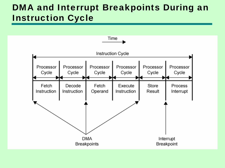
DMA and Interrupt Breakpoints During an Instruction Cycle
Aside • What effect does caching memory have
on DMA? • What about on board cache? • Hint: how much are the system buses
available?
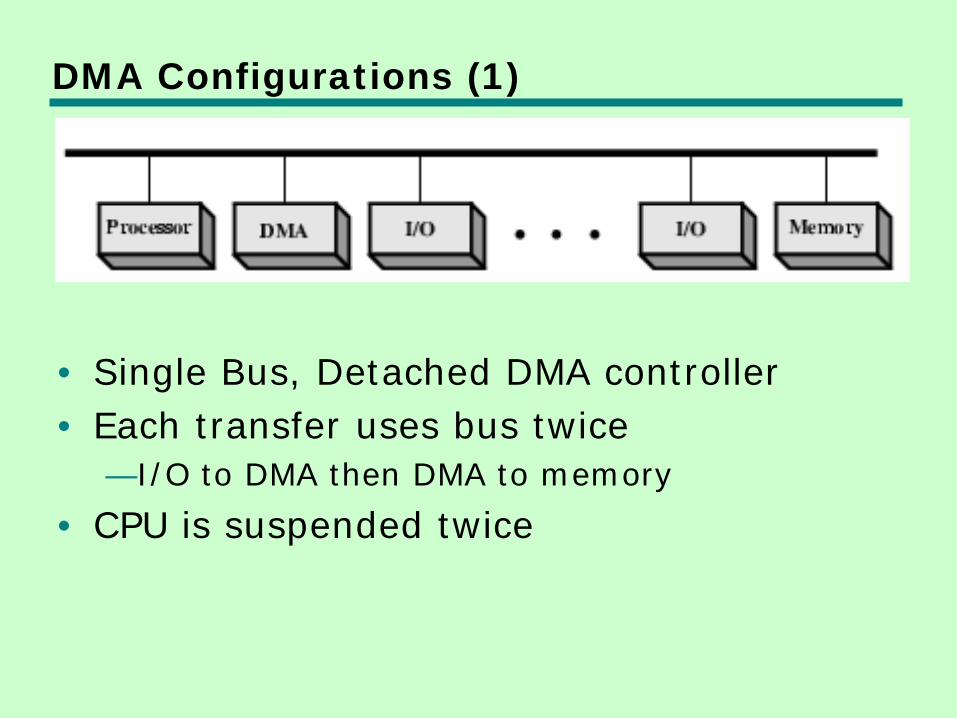
DMA Configurations (1)
• Single Bus, Detached DMA controller • Each transfer uses bus twice
—I/O to DMA then DMA to memory
• CPU is suspended twice
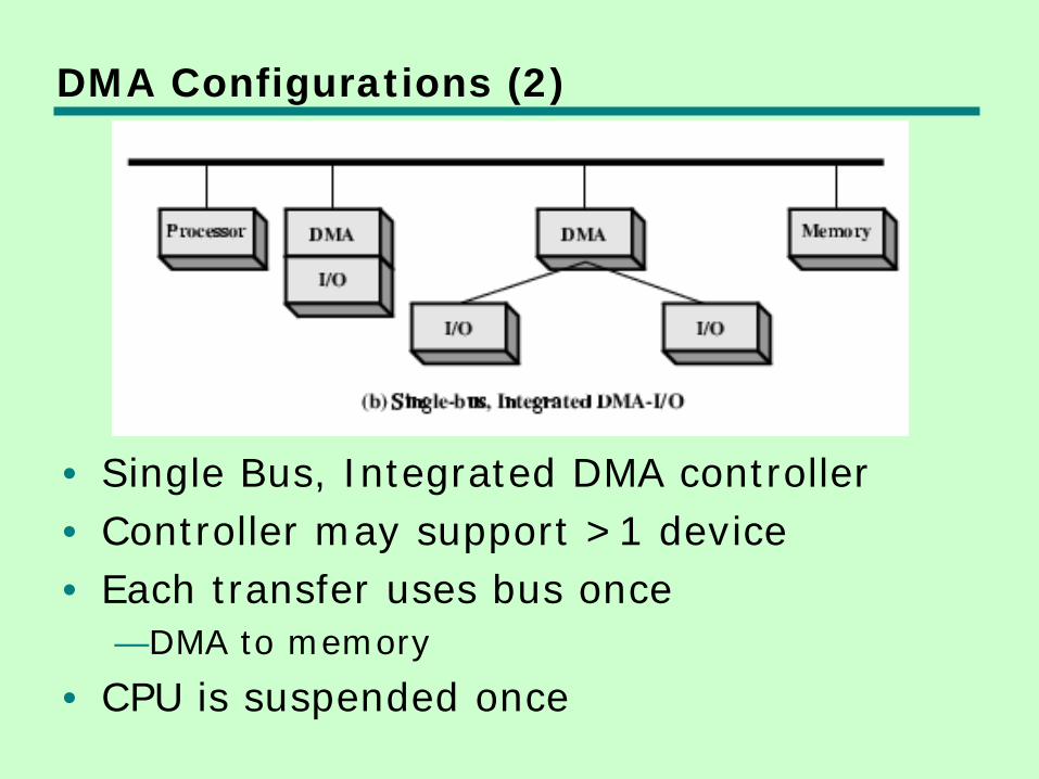
DMA Configurations (2)
• Single Bus, Integrated DMA controller • Controller may support >1 device • Each transfer uses bus once
—DMA to memory
• CPU is suspended once
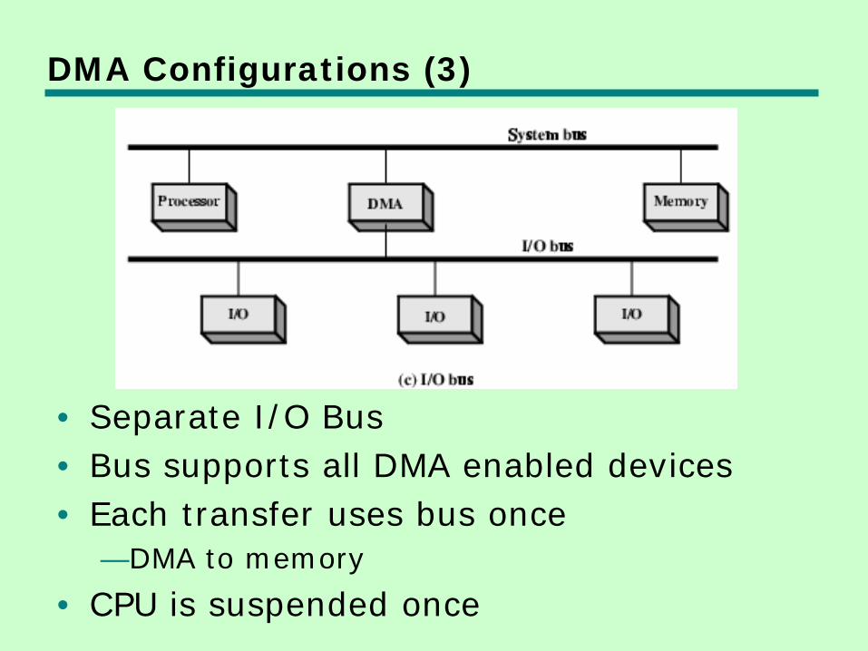
DMA Configurations (3)
• Separate I/O Bus • Bus supports all DMA enabled devices • Each transfer uses bus once
—DMA to memory
• CPU is suspended once
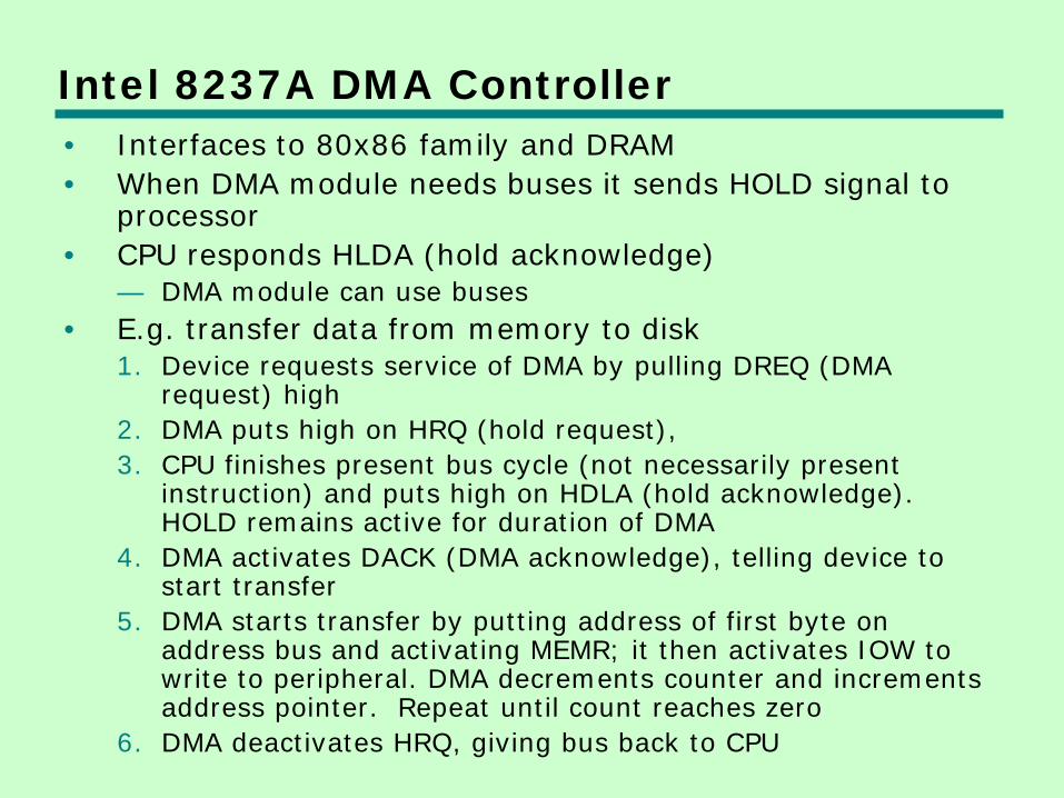
Intel 8237A DMA Controller • Interfaces to 80x86 family and DRAM • When DMA module needs buses it sends HOLD signal to
processor • CPU responds HLDA (hold acknowledge)
— DMA module can use buses • E.g. transfer data from memory to disk
1. Device requests service of DMA by pulling DREQ (DMA request) high
2. DMA puts high on HRQ (hold request), 3. CPU finishes present bus cycle (not necessarily present
instruction) and puts high on HDLA (hold acknowledge). HOLD remains active for duration of DMA
4. DMA activates DACK (DMA acknowledge), telling device to start transfer
5. DMA starts transfer by putting address of first byte on address bus and activating MEMR; it then activates IOW to write to peripheral. DMA decrements counter and increments address pointer. Repeat until count reaches zero
6. DMA deactivates HRQ, giving bus back to CPU
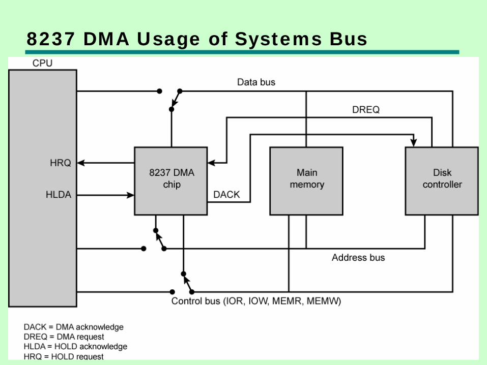
8237 DMA Usage of Systems Bus
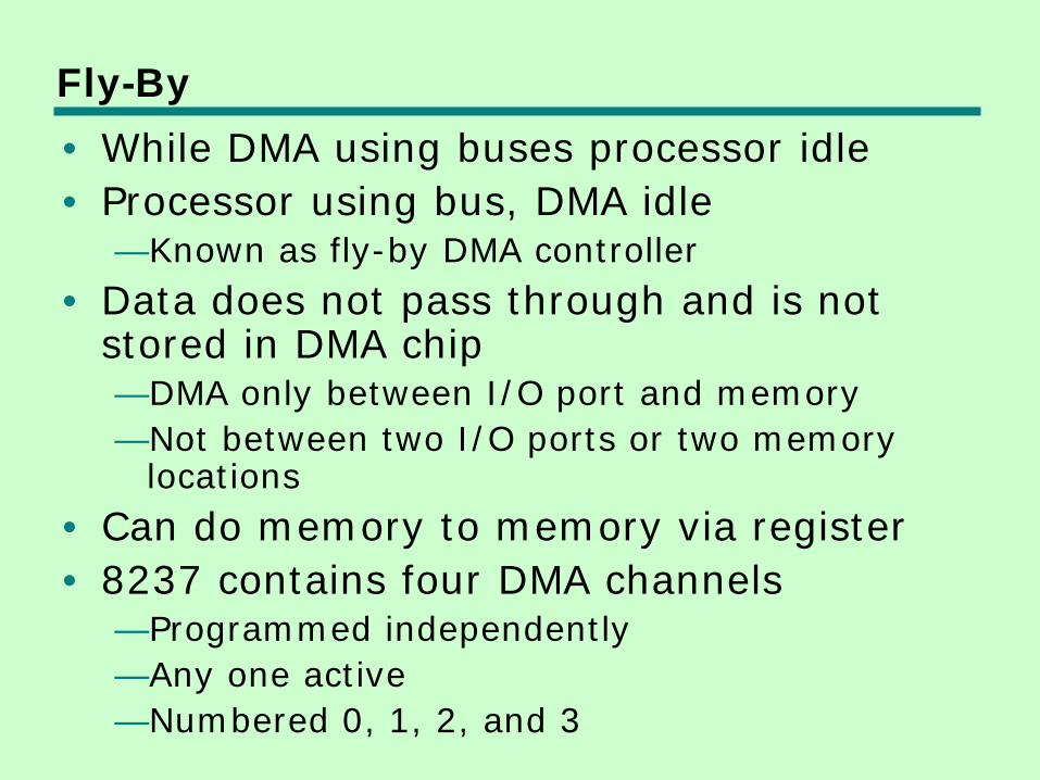
Fly-By • While DMA using buses processor idle • Processor using bus, DMA idle
—Known as fly-by DMA controller • Data does not pass through and is not
stored in DMA chip —DMA only between I/O port and memory —Not between two I/O ports or two memory
locations • Can do memory to memory via register • 8237 contains four DMA channels
—Programmed independently —Any one active —Numbered 0, 1, 2, and 3
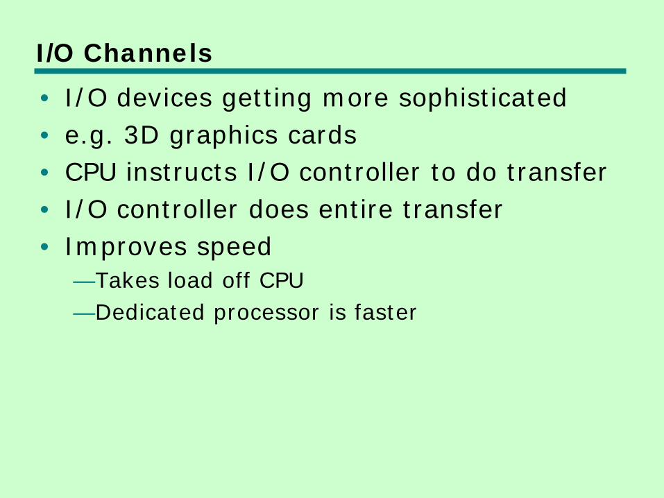
I/O Channels • I/O devices getting more sophisticated • e.g. 3D graphics cards • CPU instructs I/O controller to do transfer • I/O controller does entire transfer • Improves speed
—Takes load off CPU —Dedicated processor is faster
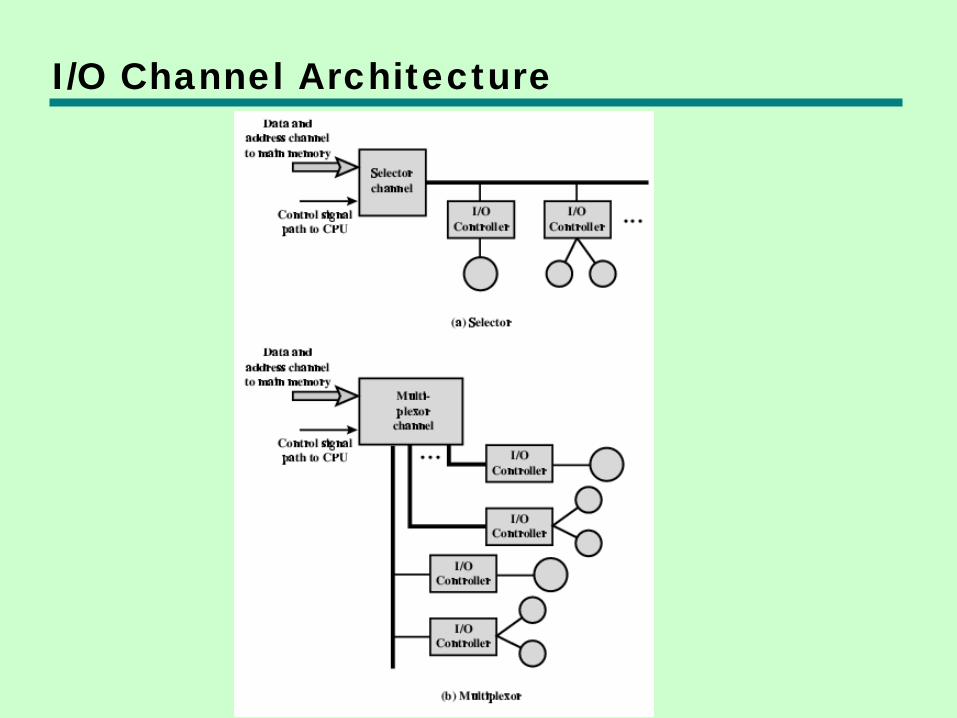
I/O Channel Architecture
Interfacing • Connecting devices together • Bit of wire? • Dedicated processor/memory/buses? • E.g. FireWire, InfiniBand
IEEE 1394 FireWire • High performance serial bus • Fast • Low cost • Easy to implement • Also being used in digital cameras, VCRs
and TV
FireWire Configuration • Daisy chain • Up to 63 devices on single port
—Really 64 of which one is the interface itself
• Up to 1022 buses can be connected with bridges
• Automatic configuration • No bus terminators • May be tree structure
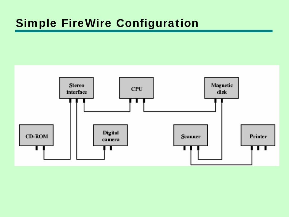
Simple FireWire Configuration
FireWire 3 Layer Stack • Physical
—Transmission medium, electrical and signaling characteristics
• Link —Transmission of data in packets
• Transaction —Request-response protocol
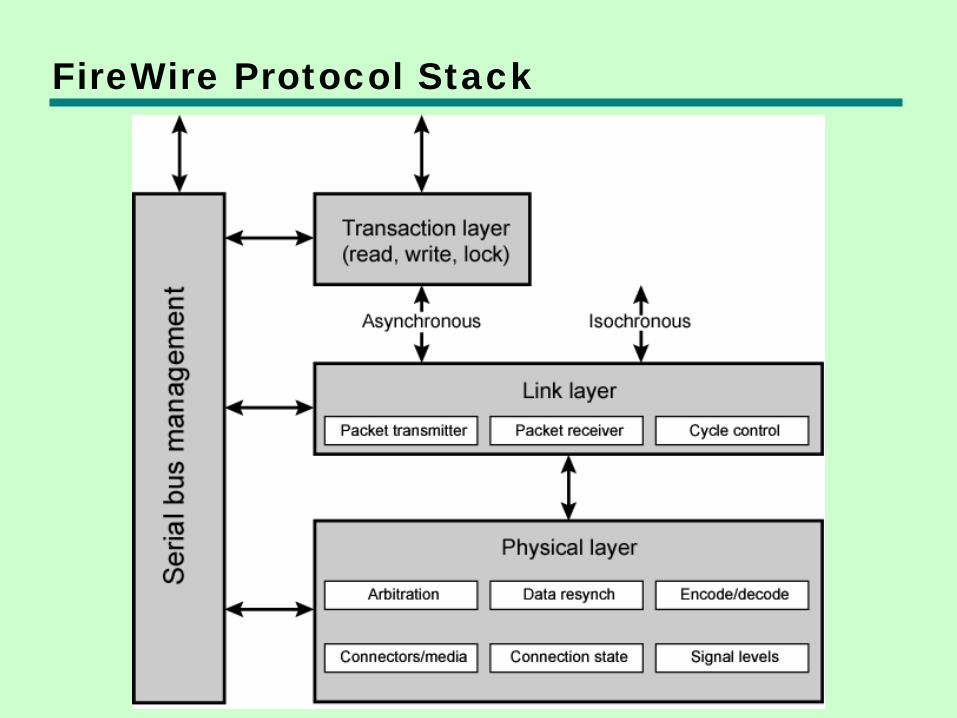
FireWire Protocol Stack
FireWire - Physical Layer • Data rates from 25 to 400Mbps • Two forms of arbitration
—Based on tree structure —Root acts as arbiter —First come first served —Natural priority controls simultaneous requests
– i.e. who is nearest to root
—Fair arbitration —Urgent arbitration
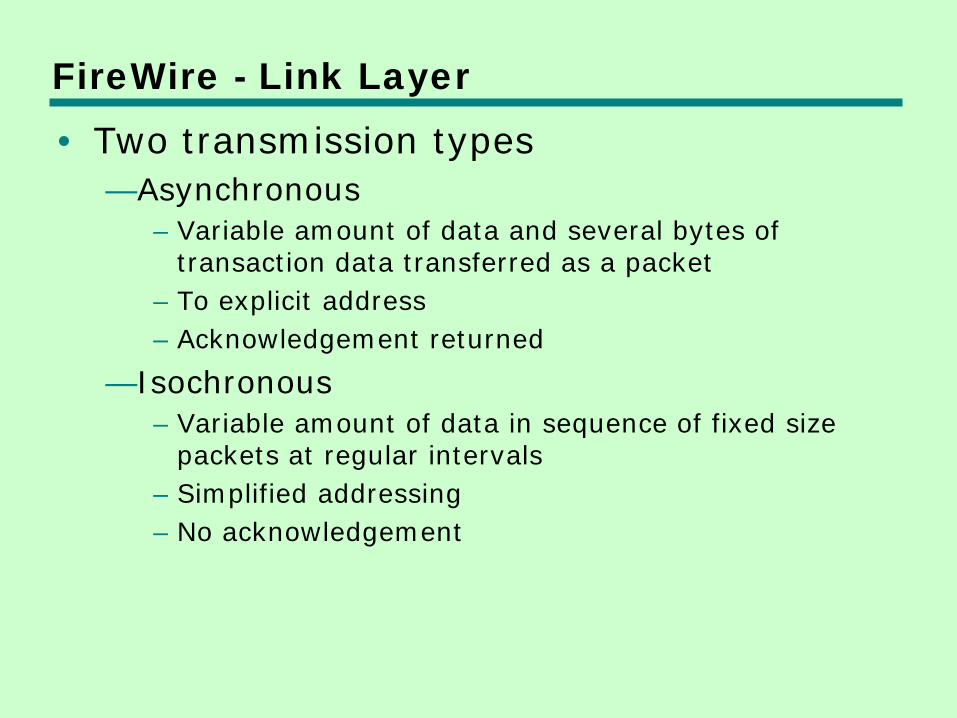
FireWire - Link Layer • Two transmission types
—Asynchronous – Variable amount of data and several bytes of
transaction data transferred as a packet – To explicit address – Acknowledgement returned
—Isochronous – Variable amount of data in sequence of fixed size
packets at regular intervals – Simplified addressing – No acknowledgement
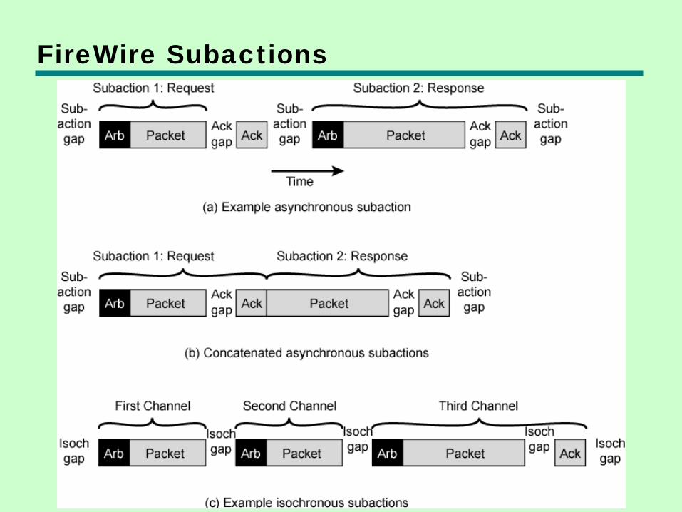
FireWire Subactions
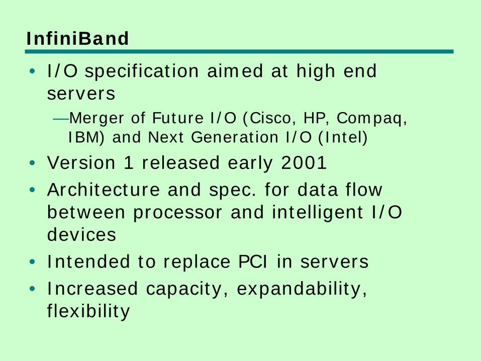
InfiniBand • I/O specification aimed at high end
servers —Merger of Future I/O (Cisco, HP, Compaq,
IBM) and Next Generation I/O (Intel)
• Version 1 released early 2001 • Architecture and spec. for data flow
between processor and intelligent I/O devices
• Intended to replace PCI in servers • Increased capacity, expandability,
flexibility
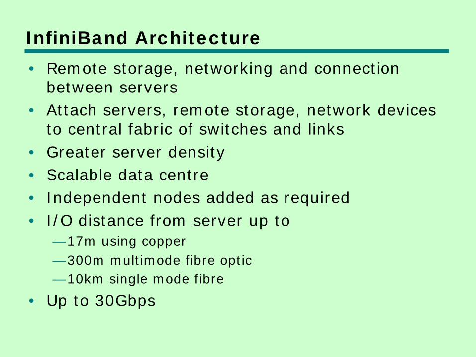
InfiniBand Architecture • Remote storage, networking and connection
between servers • Attach servers, remote storage, network devices
to central fabric of switches and links • Greater server density • Scalable data centre • Independent nodes added as required • I/O distance from server up to
—17m using copper —300m multimode fibre optic —10km single mode fibre
• Up to 30Gbps
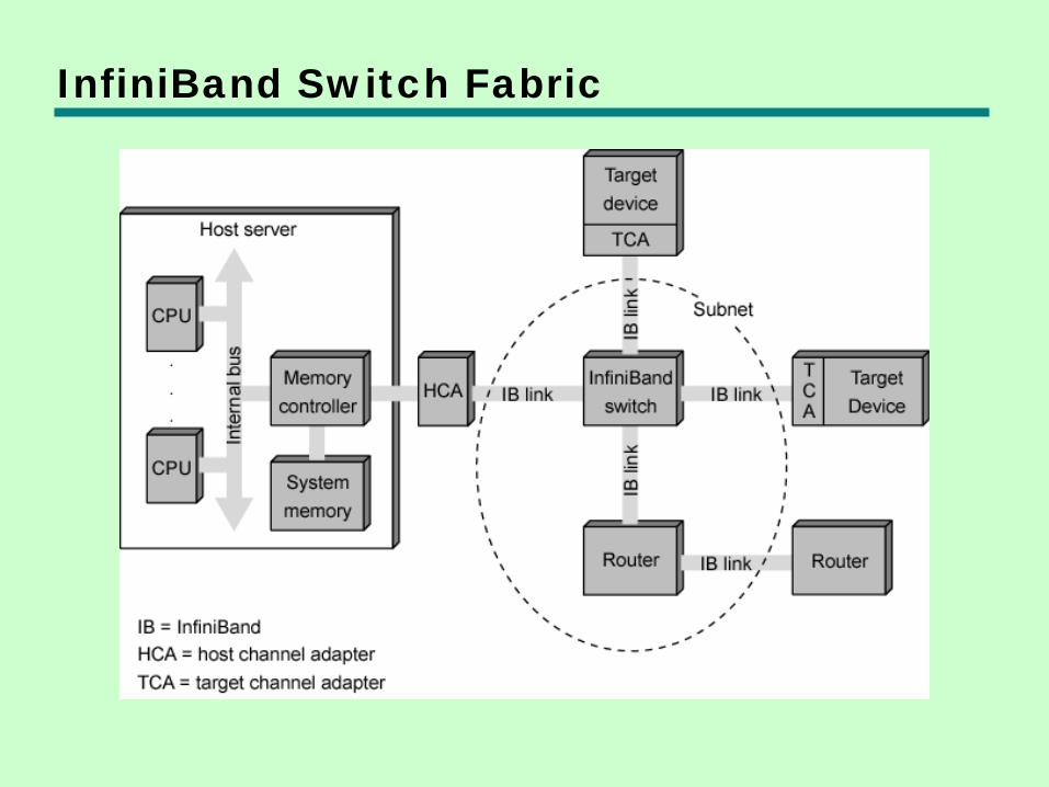
InfiniBand Switch Fabric
InfiniBand Operation • 16 logical channels (virtual lanes) per
physical link • One lane for management, rest for data • Data in stream of packets • Virtual lane dedicated temporarily to end
to end transfer • Switch maps traffic from incoming to
outgoing lane
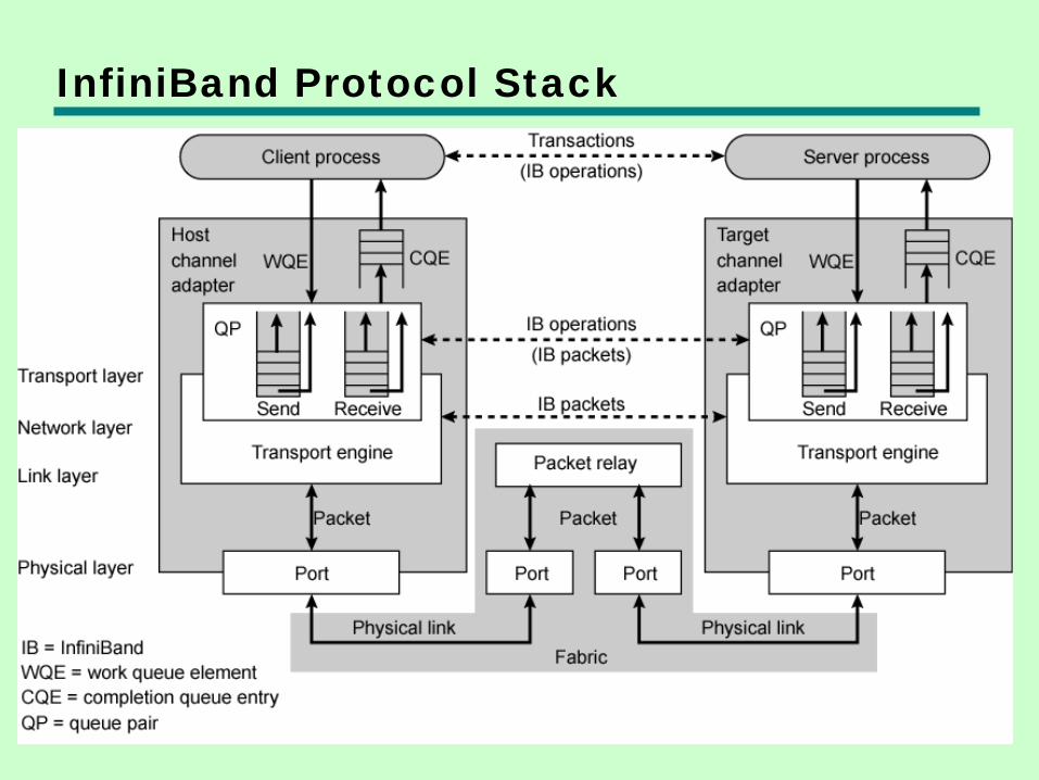
InfiniBand Protocol Stack
Foreground Reading • Check out Universal Serial Bus (USB) • Compare with other communication
standards e.g. Ethernet