Embed Size (px)
Citation preview
William Stallings Computer Organization and Architecture8th Edition
Chapter 7Input/Output
1
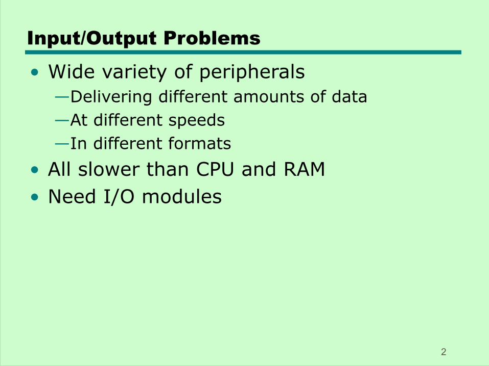
Input/Output Problems
• Wide variety of peripherals—Delivering different amounts of data—At different speeds—In different formats
• All slower than CPU and RAM• Need I/O modules
2
Input/Output Module
• Interface to CPU and Memory• Interface to one or more peripherals
3
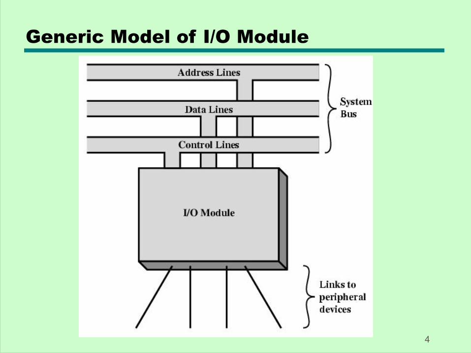
Generic Model of I/O Module
4
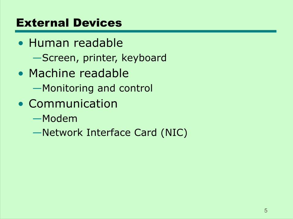
External Devices
• Human readable—Screen, printer, keyboard
• Machine readable—Monitoring and control
• Communication—Modem—Network Interface Card (NIC)
5
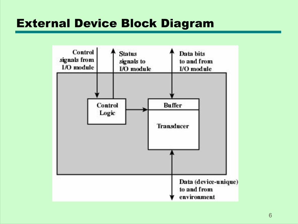
External Device Block Diagram
6
I/O Module Function
• Control & Timing• CPU Communication• Device Communication• Data Buffering• Error Detection
7
I/O Steps
• CPU checks I/O module device status• I/O module returns status• If ready, CPU requests data transfer• I/O module gets data from device• I/O module transfers data to CPU• Variations for output, DMA, etc.
8
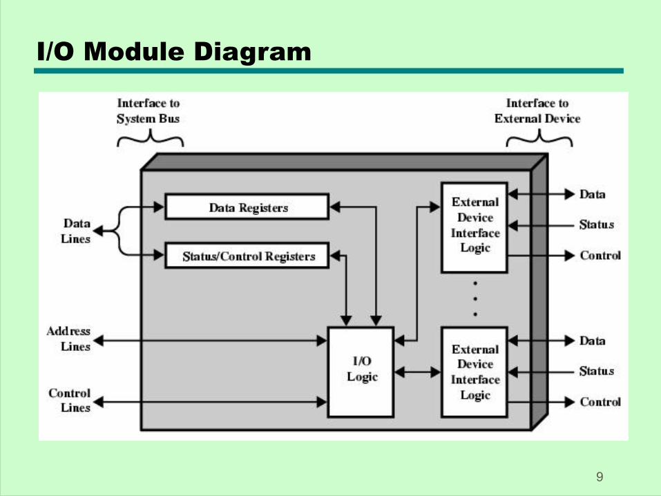
I/O Module Diagram
9
I/O Module Decisions
• Hide or reveal device properties to CPU• Support multiple or single device• Control device functions or leave for CPU• Also O/S decisions
—e.g. Unix treats everything it can as a file
10
Input Output Techniques
• Programmed• Interrupt driven• Direct Memory Access (DMA)
11
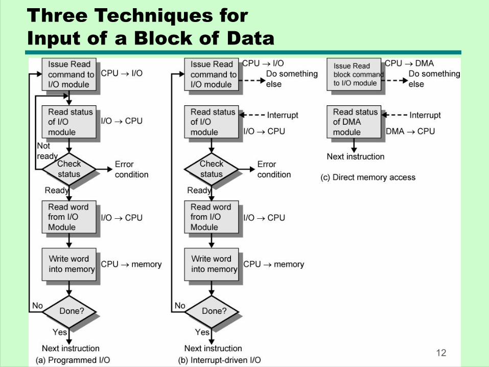
Three Techniques for Input of a Block of Data
12
Programmed I/O
• CPU has direct control over I/O—Sensing status—Read/write commands—Transferring data
• CPU waits for I/O module to complete operation
• Wastes CPU time
13
Programmed I/O - detail
• CPU requests I/O operation• I/O module performs operation• I/O module sets status bits• CPU checks status bits periodically• I/O module does not inform CPU directly• I/O module does not interrupt CPU• CPU may wait or come back later
14
I/O Commands
• CPU issues address—Identifies module (& device if >1 per module)
• CPU issues command—Control - telling module what to do
– e.g. spin up disk—Test - check status
– e.g. power? Error?—Read/Write
– Module transfers data via buffer from/to device
15
Addressing I/O Devices
• Under programmed I/O data transfer is very like memory access (CPU viewpoint)
• Each device given unique identifier• CPU commands contain identifier
(address)
16
I/O Mapping• Memory mapped I/O
—Devices and memory share an address space—I/O looks just like memory read/write—No special commands for I/O
– Large selection of memory access commands available
• Isolated I/O—Separate address spaces—Need I/O or memory select lines—Special commands for I/O
– Limited set
17
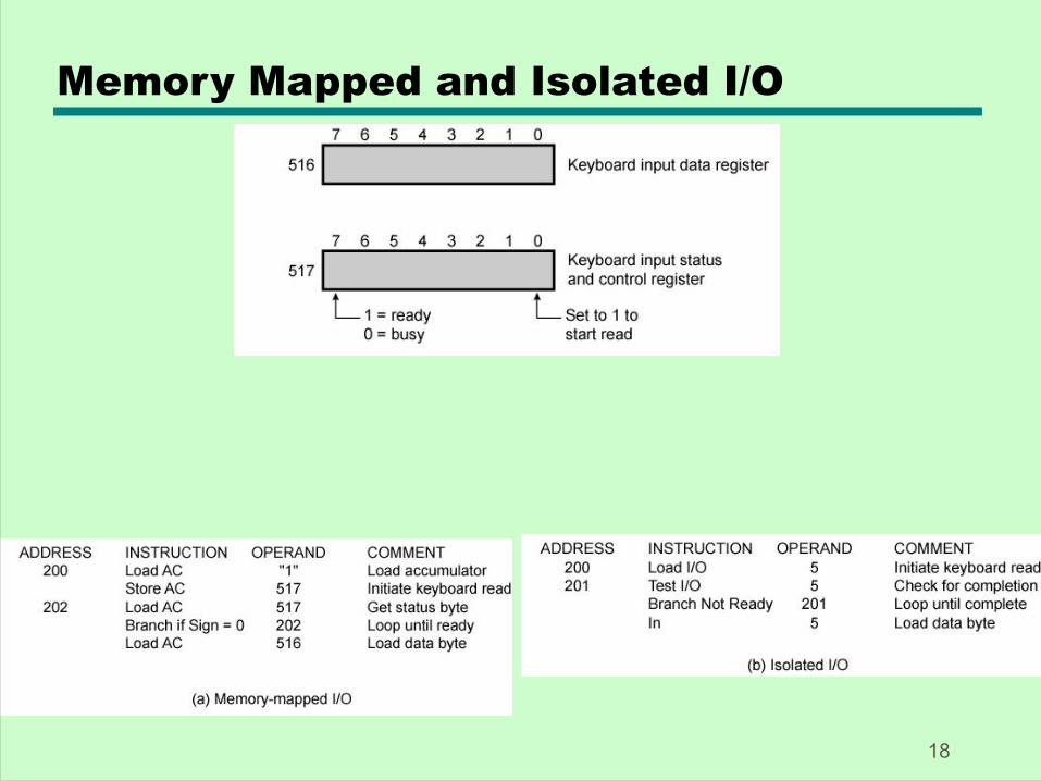
Memory Mapped and Isolated I/O
18
Interrupt Driven I/O
• Overcomes CPU waiting• No repeated CPU checking of device• I/O module interrupts when ready
19
Interrupt Driven I/OBasic Operation
• CPU issues read command• I/O module gets data from peripheral
whilst CPU does other work• I/O module interrupts CPU• CPU requests data• I/O module transfers data
20
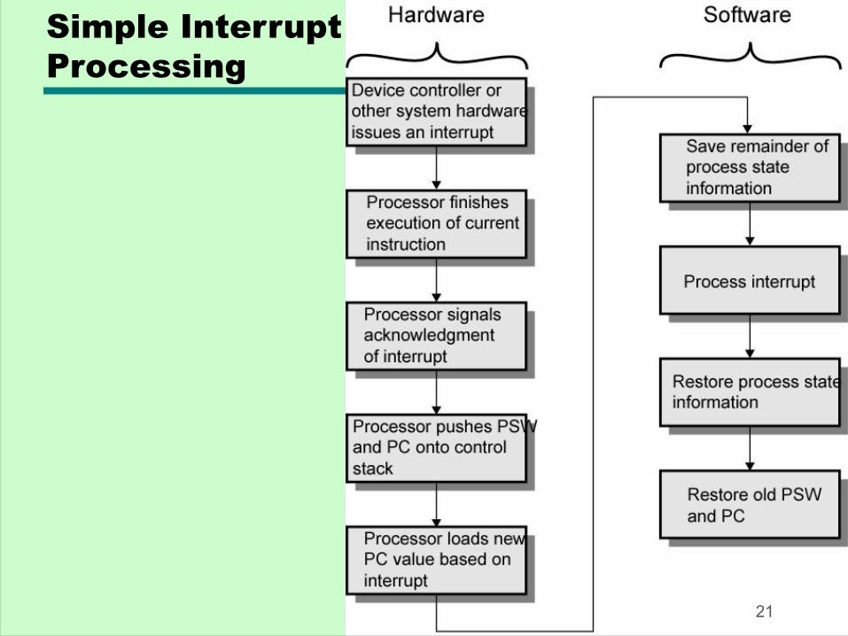
Simple InterruptProcessing
21
CPU Viewpoint
• Issue read command• Do other work• Check for interrupt at end of each
instruction cycle• If interrupted:-
—Save context (registers)—Process interrupt
– Fetch data & store
22
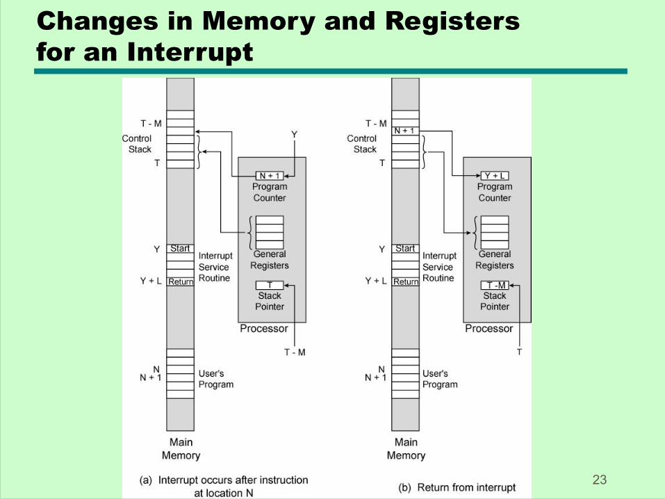
Changes in Memory and Registersfor an Interrupt
23
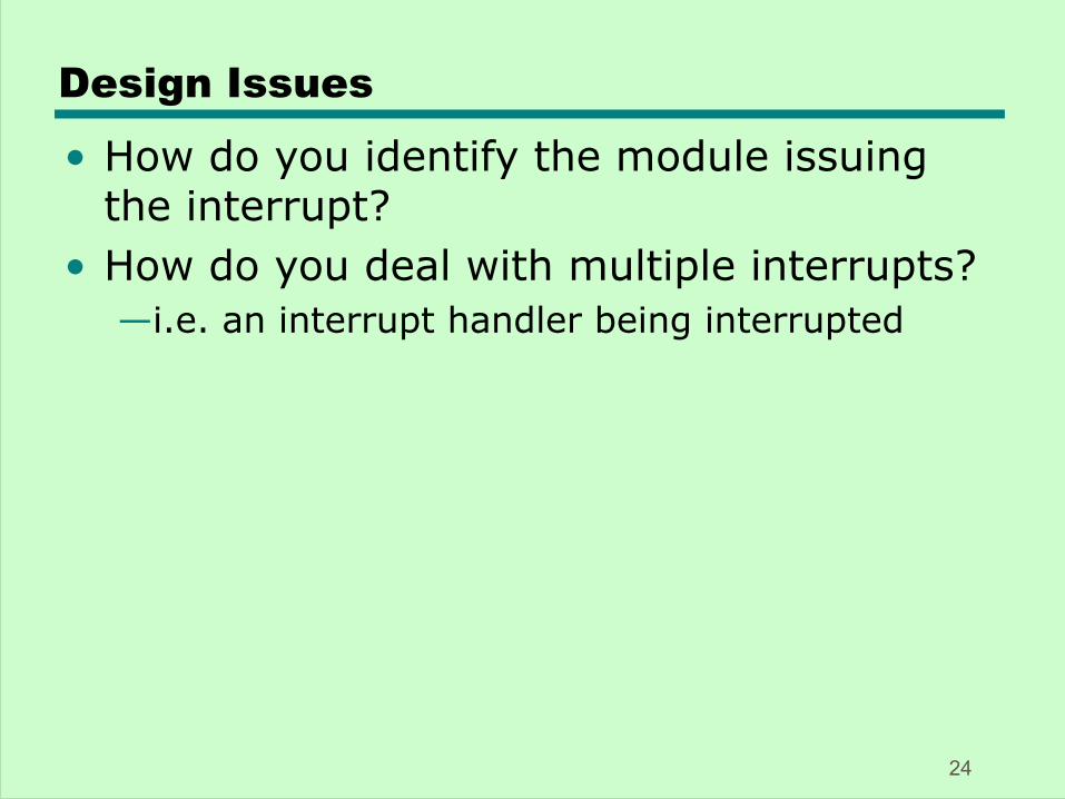
Design Issues
• How do you identify the module issuing the interrupt?
• How do you deal with multiple interrupts?—i.e. an interrupt handler being interrupted
24
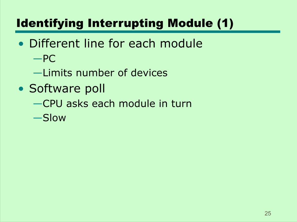
Identifying Interrupting Module (1)
• Different line for each module—PC—Limits number of devices
• Software poll—CPU asks each module in turn—Slow
25
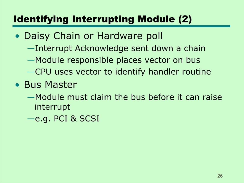
Identifying Interrupting Module (2)
• Daisy Chain or Hardware poll—Interrupt Acknowledge sent down a chain—Module responsible places vector on bus—CPU uses vector to identify handler routine
• Bus Master—Module must claim the bus before it can raise
interrupt—e.g. PCI & SCSI
26
Multiple Interrupts
• Each interrupt line has a priority• Higher priority lines can interrupt lower
priority lines• If bus mastering only current master can
interrupt
27
Example - PC Bus
• 80x86 has one interrupt line• 8086 based systems use one 8259A
interrupt controller• 8259A has 8 interrupt lines
28
Sequence of Events
• 8259A accepts interrupts• 8259A determines priority• 8259A signals 8086 (raises INTR line)• CPU Acknowledges• 8259A puts correct vector on data bus• CPU processes interrupt
29
ISA Bus Interrupt System
• ISA bus chains two 8259As together• Link is via interrupt 2• Gives 15 lines
—16 lines less one for link• IRQ 9 is used to re-route anything trying
to use IRQ 2—Backwards compatibility
• Incorporated in chip set
30
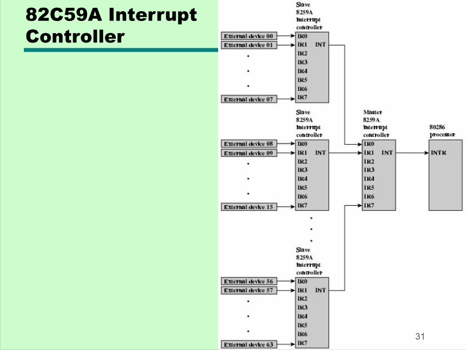
82C59A InterruptController
31
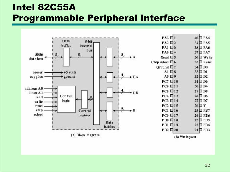
Intel 82C55A Programmable Peripheral Interface
32
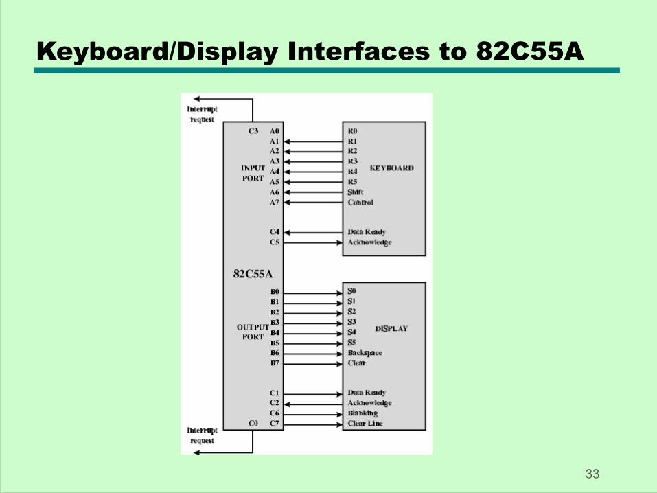
Keyboard/Display Interfaces to 82C55A
33
Direct Memory Access
• Interrupt driven and programmed I/O require active CPU intervention—Transfer rate is limited—CPU is tied up
• DMA is the answer
34

DMA Function
• Additional Module (hardware) on bus• DMA controller takes over from CPU for
I/O
35
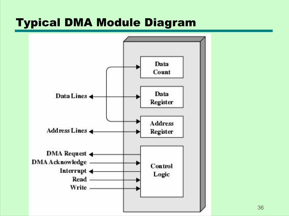
Typical DMA Module Diagram
36
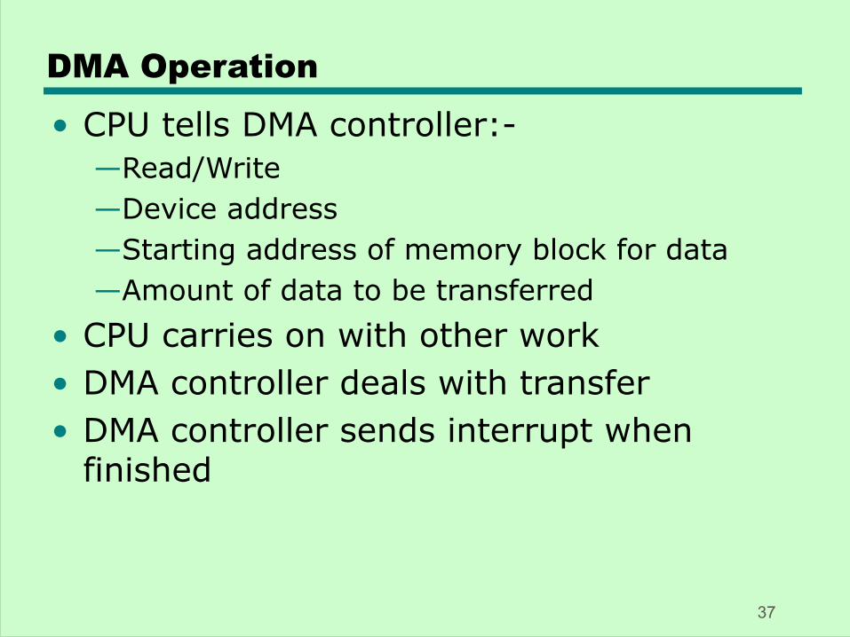
DMA Operation
• CPU tells DMA controller:-—Read/Write—Device address—Starting address of memory block for data—Amount of data to be transferred
• CPU carries on with other work• DMA controller deals with transfer• DMA controller sends interrupt when
finished
37
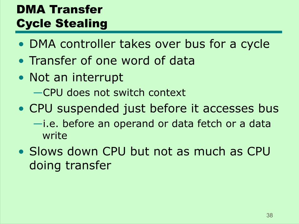
DMA TransferCycle Stealing
• DMA controller takes over bus for a cycle• Transfer of one word of data• Not an interrupt
—CPU does not switch context• CPU suspended just before it accesses bus
—i.e. before an operand or data fetch or a data write
• Slows down CPU but not as much as CPU doing transfer
38
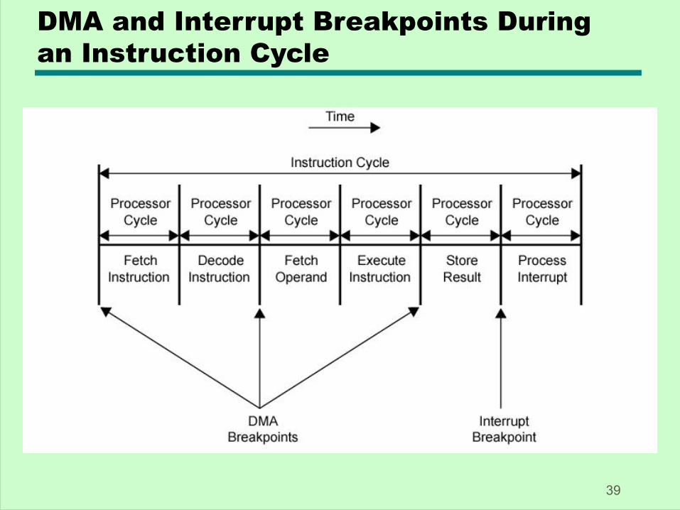
DMA and Interrupt Breakpoints During an Instruction Cycle
39
Aside
• What effect does caching memory have on DMA?
• What about on board cache?• Hint: how much are the system buses
available?
40
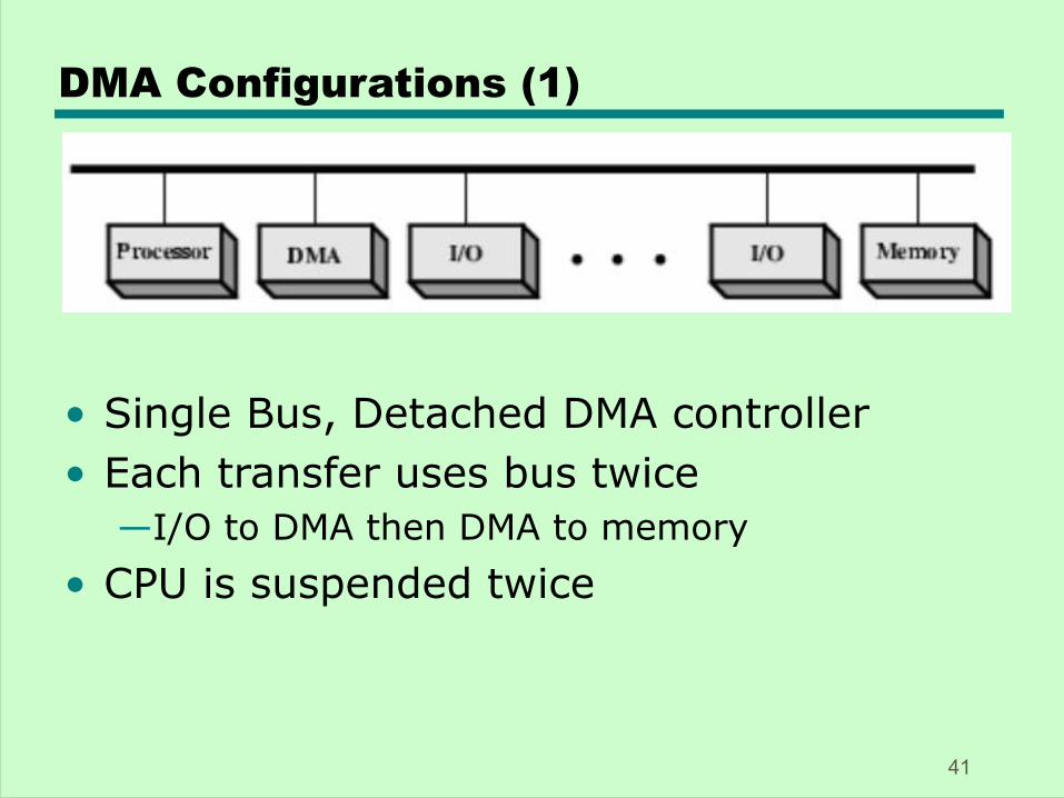
DMA Configurations (1)
• Single Bus, Detached DMA controller• Each transfer uses bus twice
—I/O to DMA then DMA to memory• CPU is suspended twice
41
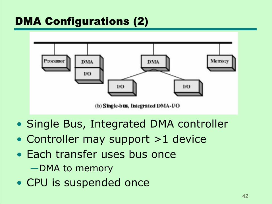
DMA Configurations (2)
• Single Bus, Integrated DMA controller• Controller may support >1 device• Each transfer uses bus once
—DMA to memory• CPU is suspended once
42
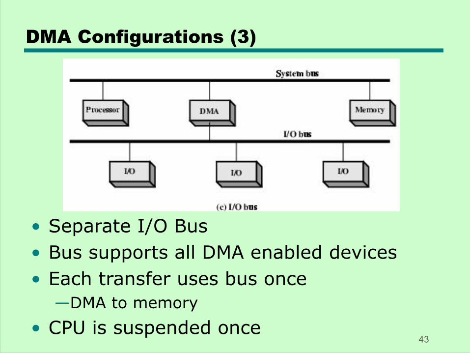
DMA Configurations (3)
• Separate I/O Bus• Bus supports all DMA enabled devices• Each transfer uses bus once
—DMA to memory• CPU is suspended once
43
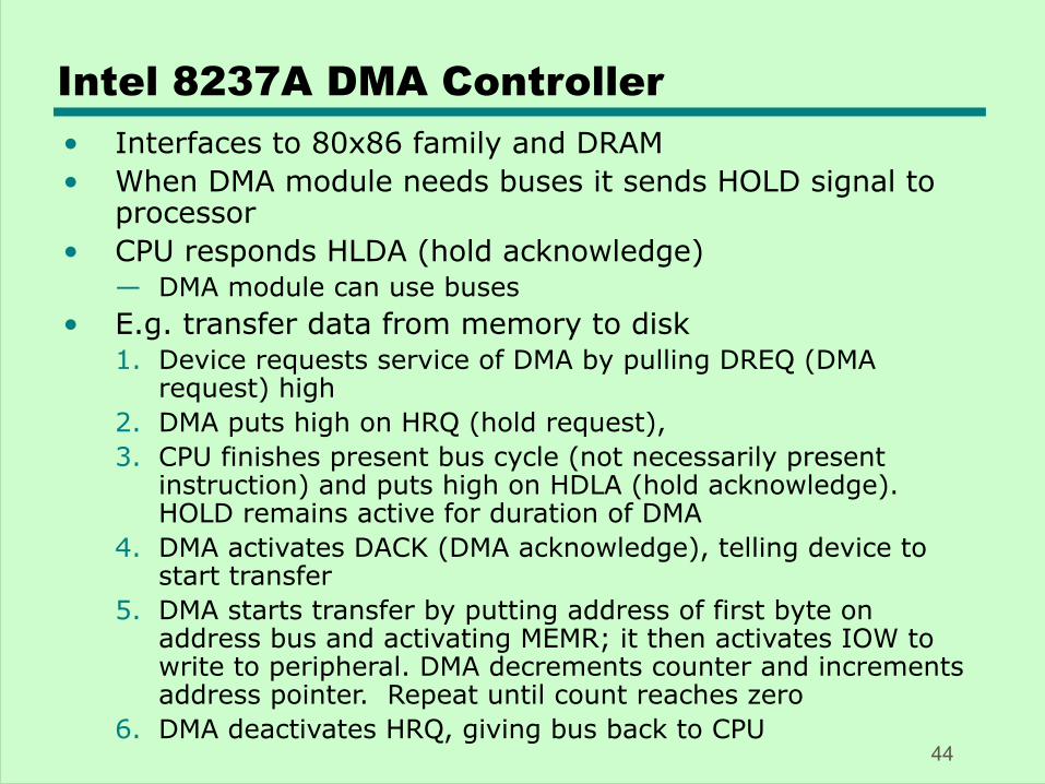
Intel 8237A DMA Controller• Interfaces to 80x86 family and DRAM• When DMA module needs buses it sends HOLD signal to
processor• CPU responds HLDA (hold acknowledge)
— DMA module can use buses• E.g. transfer data from memory to disk
1. Device requests service of DMA by pulling DREQ (DMA request) high
2. DMA puts high on HRQ (hold request), 3. CPU finishes present bus cycle (not necessarily present
instruction) and puts high on HDLA (hold acknowledge). HOLD remains active for duration of DMA
4. DMA activates DACK (DMA acknowledge), telling device to start transfer
5. DMA starts transfer by putting address of first byte on address bus and activating MEMR; it then activates IOW to write to peripheral. DMA decrements counter and increments address pointer. Repeat until count reaches zero
6. DMA deactivates HRQ, giving bus back to CPU44
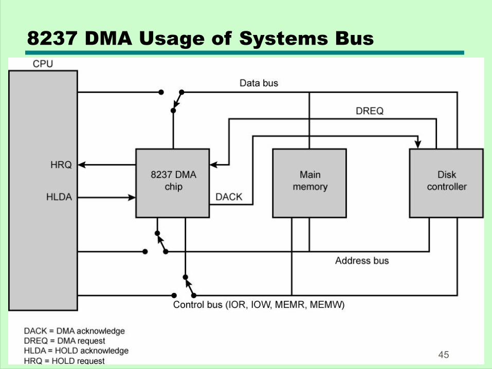
8237 DMA Usage of Systems Bus
45


![Cap 5 [8th Ed. Stallings]](https://img.pdfslide.net/doc/110x75/55cf94e1550346f57ba511ec/cap-5-8th-ed-stallings.jpg)