Embed Size (px)
Citation preview
+
William Stallings
Computer Organization
and Architecture
10th Edition
© 2016 Pearson Education, Inc., Hoboken,
NJ. All rights reserved.
+ Chapter 14Processor Structure and Function
© 2016 Pearson Education, Inc., Hoboken, NJ. All rights reserved.
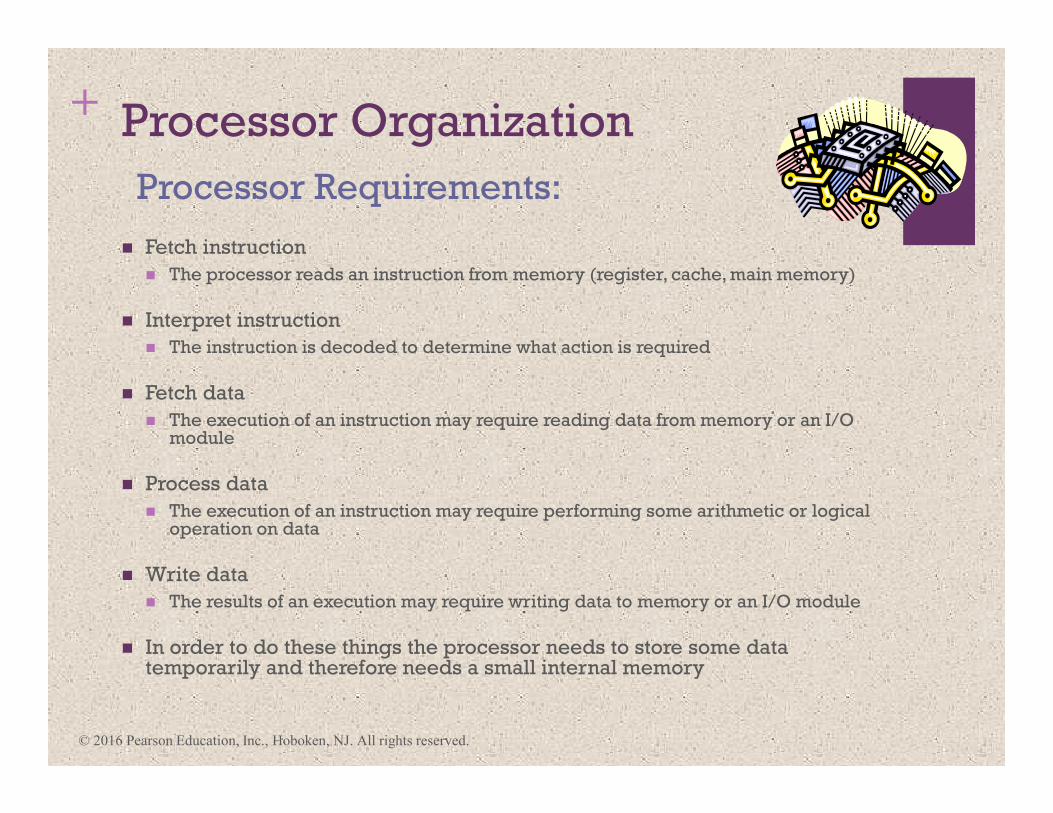
+ Processor Organization
� Fetch instruction
� The processor reads an instruction from memory (register, cache, main memory)
� Interpret instruction
� The instruction is decoded to determine what action is required
� Fetch data
� The execution of an instruction may require reading data from memory or an I/O module
� Process data
� The execution of an instruction may require performing some arithmetic or logical operation on data
� Write data
� The results of an execution may require writing data to memory or an I/O module
� In order to do these things the processor needs to store some data temporarily and therefore needs a small internal memory
Processor Requirements:
© 2016 Pearson Education, Inc., Hoboken, NJ. All rights reserved.
© 2016 Pearson Education, Inc., Hoboken, NJ. All rights reserved.
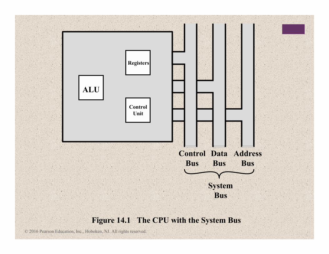
Figure 14.1 The CPU with the System Bus
Control
Bus
Data
Bus
Address
Bus
System
Bus
ALU
Registers
Control
Unit
© 2016 Pearson Education, Inc., Hoboken, NJ. All rights reserved.
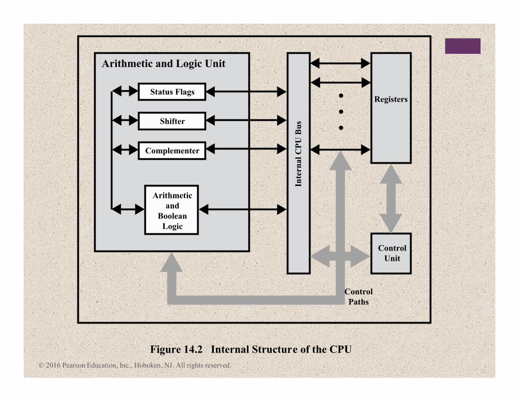
Control
Unit
Registers
Arithmetic
and
Boolean
Logic
Complementer
Inte
rna
l C
PU
Bu
sShifter
Status Flags
Arithmetic and Logic Unit
Figure 14.2 Internal Structure of the CPU
Control
Paths
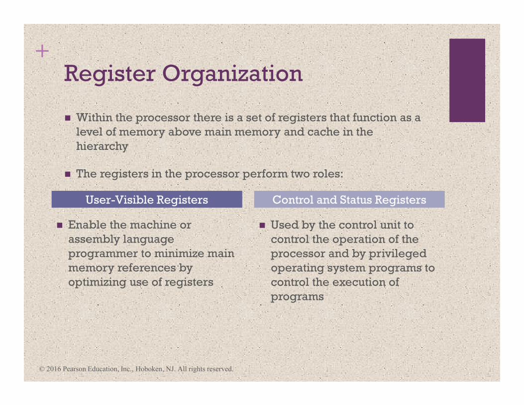
+Register Organization
� Enable the machine or
assembly language
programmer to minimize main
memory references by
optimizing use of registers
� Used by the control unit to
control the operation of the
processor and by privileged
operating system programs to
control the execution of
programs
User-Visible Registers Control and Status Registers
� Within the processor there is a set of registers that function as a
level of memory above main memory and cache in the
hierarchy
� The registers in the processor perform two roles:
© 2016 Pearson Education, Inc., Hoboken, NJ. All rights reserved.
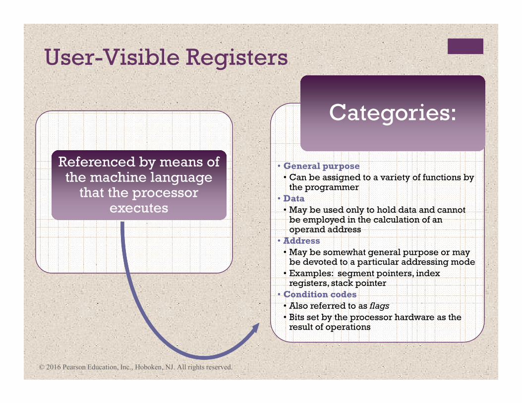
User-Visible Registers
Referenced by means of the machine language
that the processor executes
Referenced by means of the machine language
that the processor executes
• General purpose
• Can be assigned to a variety of functions by the programmer
• Data
• May be used only to hold data and cannot be employed in the calculation of an operand address
• Address
• May be somewhat general purpose or may be devoted to a particular addressing mode
• Examples: segment pointers, index registers, stack pointer
• Condition codes
• Also referred to as flags
• Bits set by the processor hardware as the result of operations
Categories:Categories:
© 2016 Pearson Education, Inc., Hoboken, NJ. All rights reserved.

Table 14.1
Condition Codes
Advantages Disadvantages
1. Because condition codes are set by normal
arithmetic and data movement instructions,
they should reduce the number of
COMPARE and TEST instructions needed.
2. Conditional instructions, such as BRANCH
are simplified relative to composite
instructions, such as TEST AND BRANCH.
3. Condition codes facilitate multiway
branches. For example, a TEST instruction
can be followed by two branches, one on
less than or equal to zero and one on
greater than zero.
4. Condition codes can be saved on the stack
during subroutine calls along with other
register information.
1. Condition codes add complexity, both to
the hardware and software. Condition code
bits are often modified in different ways
by different instructions, making life more
difficult for both the microprogrammer
and compiler writer.
2. Condition codes are irregular; they are typically not part of the main data path, so
they require extra hardware connections.
3. Often condition code machines must add
special non-condition-code instructions for
special situations anyway, such as bit
checking, loop control, and atomic
semaphore operations. 4. In a pipelined implementation, condition
codes require special synchronization to
avoid conflicts.
© 2016 Pearson Education, Inc., Hoboken, NJ. All rights reserved.
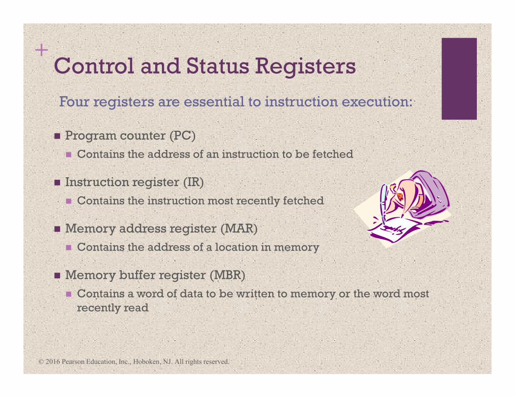
+Control and Status Registers
� Program counter (PC)
� Contains the address of an instruction to be fetched
� Instruction register (IR)
� Contains the instruction most recently fetched
� Memory address register (MAR)
� Contains the address of a location in memory
� Memory buffer register (MBR)
� Contains a word of data to be written to memory or the word most
recently read
Four registers are essential to instruction execution:
© 2016 Pearson Education, Inc., Hoboken, NJ. All rights reserved.
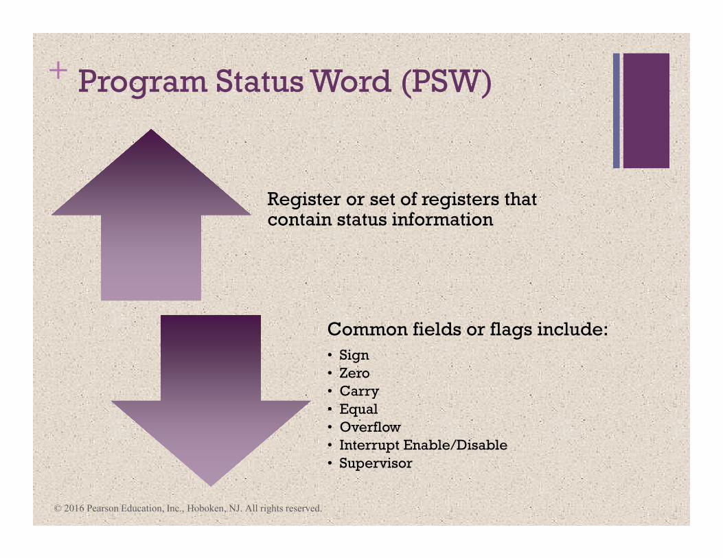
+ Program Status Word (PSW)
Register or set of registers that contain status information
Common fields or flags include:
• Sign
• Zero
• Carry
• Equal
• Overflow
• Interrupt Enable/Disable
• Supervisor
© 2016 Pearson Education, Inc., Hoboken, NJ. All rights reserved.
© 2016 Pearson Education, Inc., Hoboken, NJ. All rights reserved.
AXEAX
BXEBX
CXECX
DXEDX
SPESP
BPEBP
SIESI
DI
Program Status
General Registers
EDI
AX
BX
CX
DX
SP
BP
SI
DI
CS
DS
SS
ES
FLAGS Register
Instruction Pointer
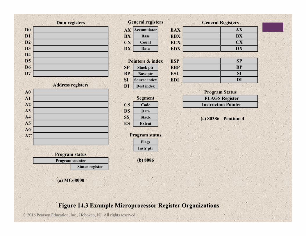
Figure 14.3 Example Microprocessor Register Organizations
(a) MC68000
Status register
Program counter
Program status
Address registers
Data registers
D0
D1
D2
D3
D4
D5
D6
D7
A0
A1
A2
A3
A4
A5
A6
A7´
(b) 8086
Instr ptr
Flags
Extrat
Stack
Data
Code
Dest index
Source index
Base ptr
Stack ptr
Data
Count
Base
Accumulator
Program status
Segment
Pointers & index
General registers
(c) 80386 - Pentium 4
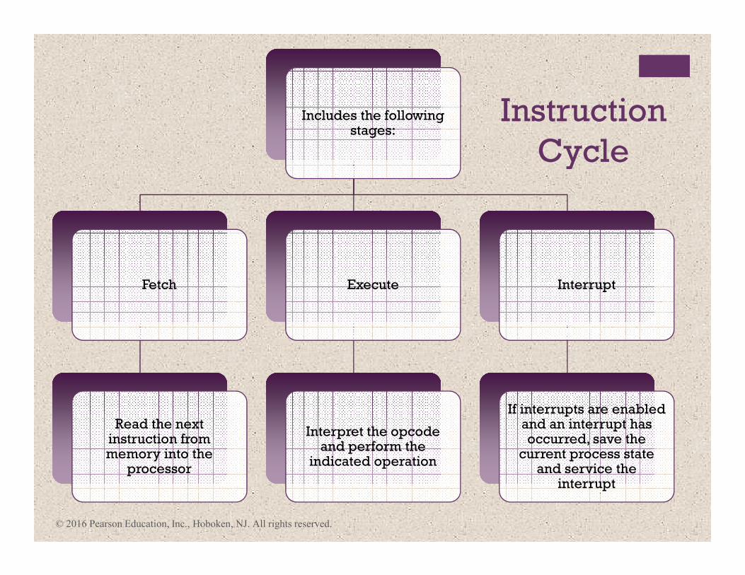
Instruction
Cycle
Includes the following stages:
Fetch
Read the next instruction from memory into the
processor
Execute
Interpret the opcode and perform the
indicated operation
Interrupt
If interrupts are enabled and an interrupt has occurred, save the
current process state and service the
interrupt
© 2016 Pearson Education, Inc., Hoboken, NJ. All rights reserved.
© 2016 Pearson Education, Inc., Hoboken, NJ. All rights reserved.
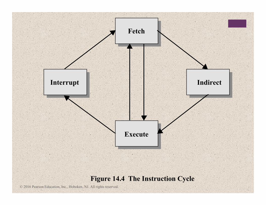
Fetch
Figure 14.4 The Instruction Cycle
Execute
Interrupt Indirect
© 2016 Pearson Education, Inc., Hoboken, NJ. All rights reserved.
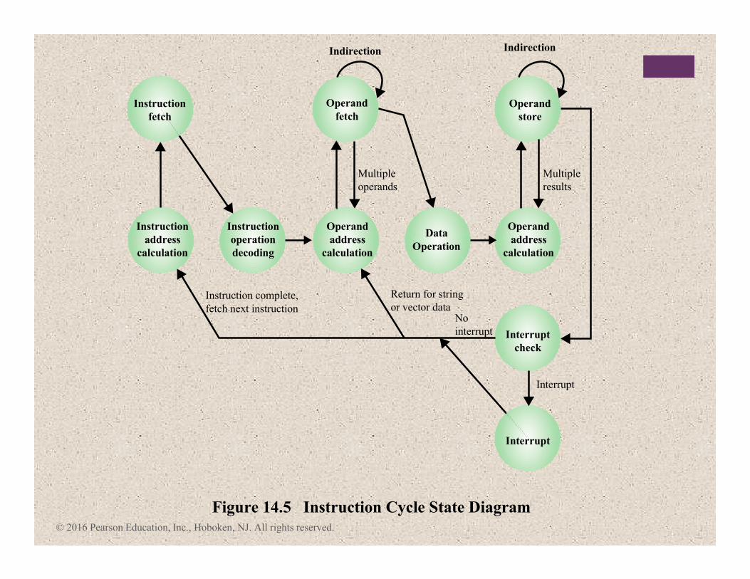
Instruction
address
calculation
Instruction
operation
decoding
Operand
address
calculation
Data
Operation
Operand
address
calculation
Instruction
fetch
Instruction complete,
fetch next instruction
Multiple
operands
Return for string
or vector data
Figure 14.5 Instruction Cycle State Diagram
No
interrupt
Interrupt
Operand
fetch
Indirection
Operand
store
Interrupt
check
Interrupt
Multiple
results
Indirection
© 2016 Pearson Education, Inc., Hoboken, NJ. All rights reserved.
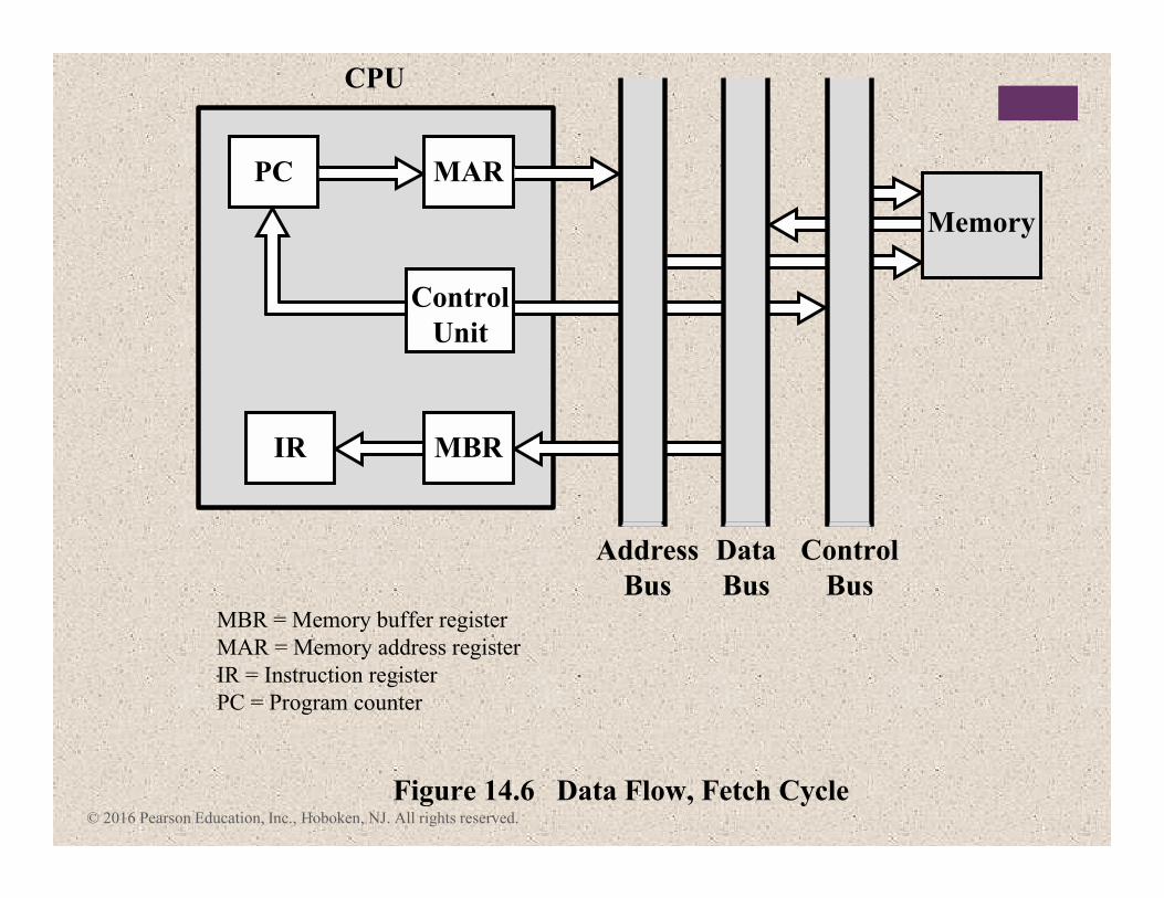
Figure 14.6 Data Flow, Fetch Cycle
Address
Bus
Data
Bus
Control
Bus
PC
CPU
MAR
Control
Unit
Memory
MBR
MBR = Memory buffer register
MAR = Memory address register
IR = Instruction register
PC = Program counter
IR
© 2016 Pearson Education, Inc., Hoboken, NJ. All rights reserved.
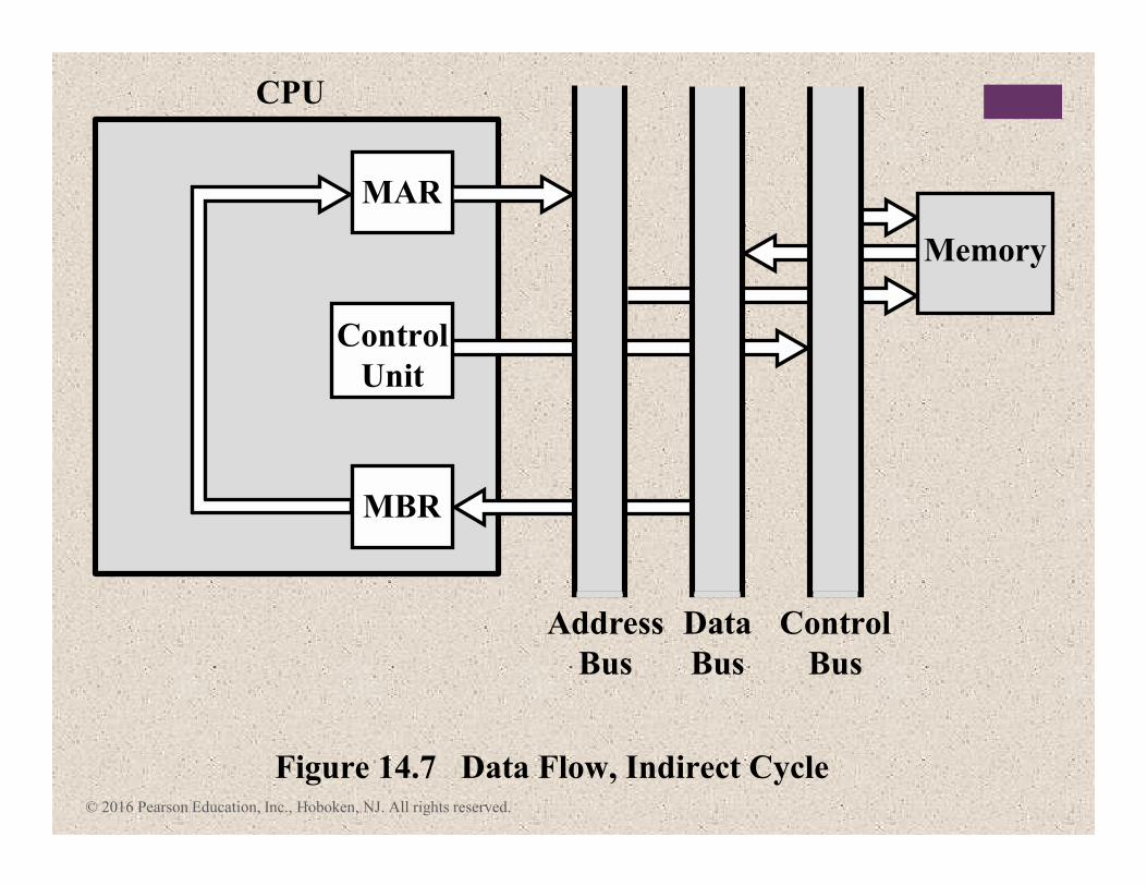
Figure 14.7 Data Flow, Indirect Cycle
Address
Bus
Data
Bus
Control
Bus
MAR
CPU
Control
Unit
Memory
MBR
© 2016 Pearson Education, Inc., Hoboken, NJ. All rights reserved.
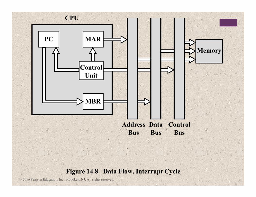
Figure 14.8 Data Flow, Interrupt Cycle
Address
Bus
Data
Bus
Control
Bus
PC
CPU
Memory
MBR
MAR
Control
Unit
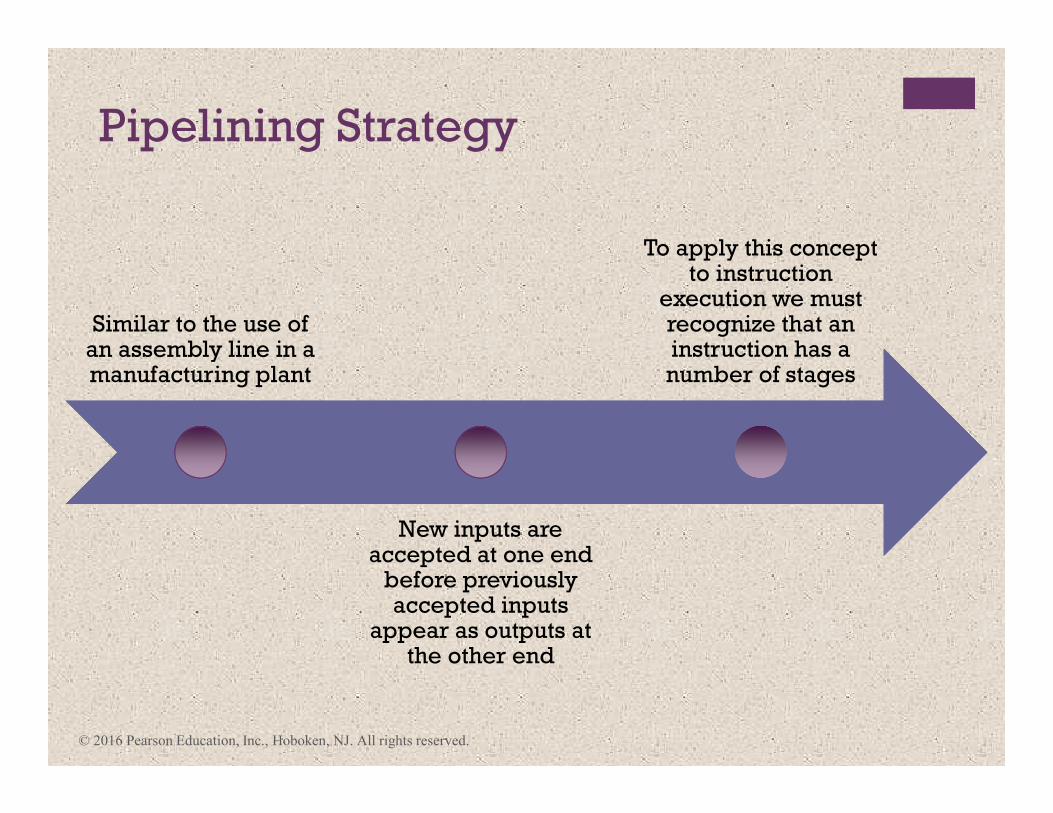
Pipelining Strategy
Similar to the use of an assembly line in a manufacturing plant
New inputs are accepted at one end
before previously accepted inputs
appear as outputs at the other end
To apply this concept to instruction
execution we must recognize that an instruction has a number of stages
© 2016 Pearson Education, Inc., Hoboken, NJ. All rights reserved.
© 2016 Pearson Education, Inc., Hoboken, NJ. All rights reserved.
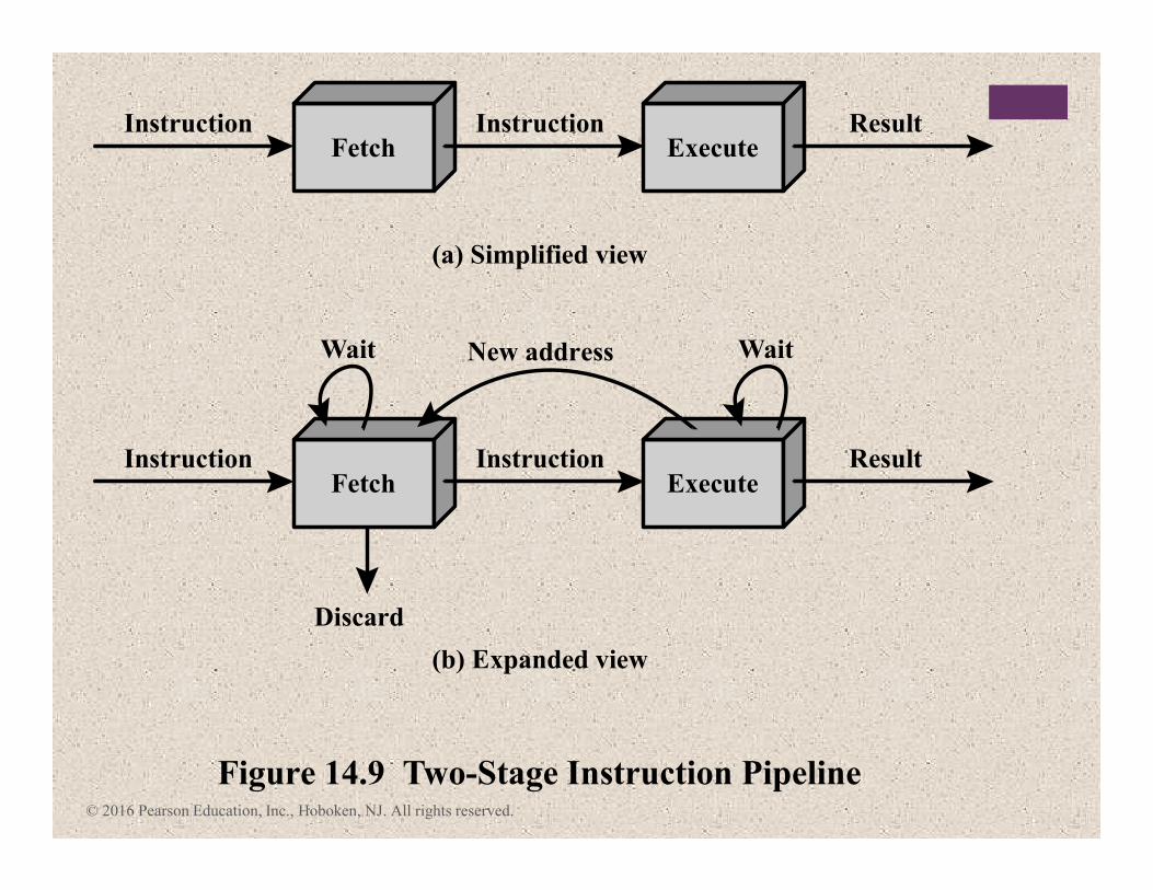
FetchInstruction Instruction
(a) Simplified view
ResultExecute
FetchInstruction
Discard
Instruction
New addressWait Wait
(b) Expanded view
Figure 14.9 Two-Stage Instruction Pipeline
ResultExecute
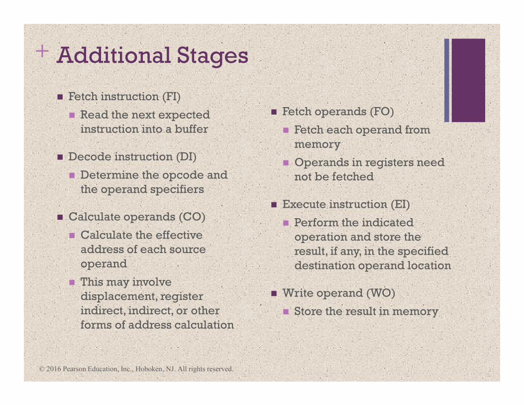
+ Additional Stages
� Fetch instruction (FI)
� Read the next expected
instruction into a buffer
� Decode instruction (DI)
� Determine the opcode and
the operand specifiers
� Calculate operands (CO)
� Calculate the effective
address of each source
operand
� This may involve
displacement, register
indirect, indirect, or other
forms of address calculation
� Fetch operands (FO)
� Fetch each operand from
memory
� Operands in registers need
not be fetched
� Execute instruction (EI)
� Perform the indicated
operation and store the
result, if any, in the specified
destination operand location
� Write operand (WO)
� Store the result in memory
© 2016 Pearson Education, Inc., Hoboken, NJ. All rights reserved.
© 2016 Pearson Education, Inc., Hoboken, NJ. All rights reserved.
1
Instruction 1
Time
FI
Instruction 2
Instruction 3
Instruction 4
Instruction 5
Instruction 6
Instruction 7
Instruction 8
Instruction 9
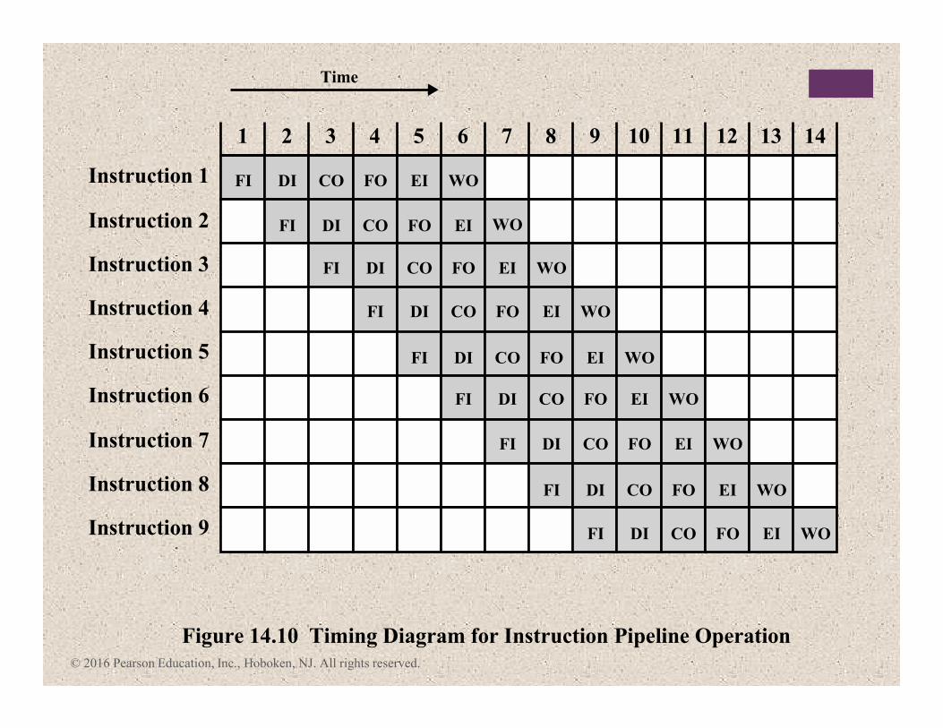
Figure 14.10 Timing Diagram for Instruction Pipeline Operation
2 3 4 5 6 7 8 9 10 11 12 13 14
DI CO FO EI WO
WOFI DI CO FO EI
FI DI CO FO EI WO
FI DI CO FO EI WO
FI DI CO FO EI WO
FI DI CO FO EI WO
FI DI CO FO EI WO
FI DI CO FO EI WO
FI DI CO FO EI WO
© 2016 Pearson Education, Inc., Hoboken, NJ. All rights reserved.
1
Instruction 1
Time
Instruction 2
Instruction 3
Instruction 4
Instruction 5
Instruction 6
Instruction 7
Instruction 15
Instruction 16
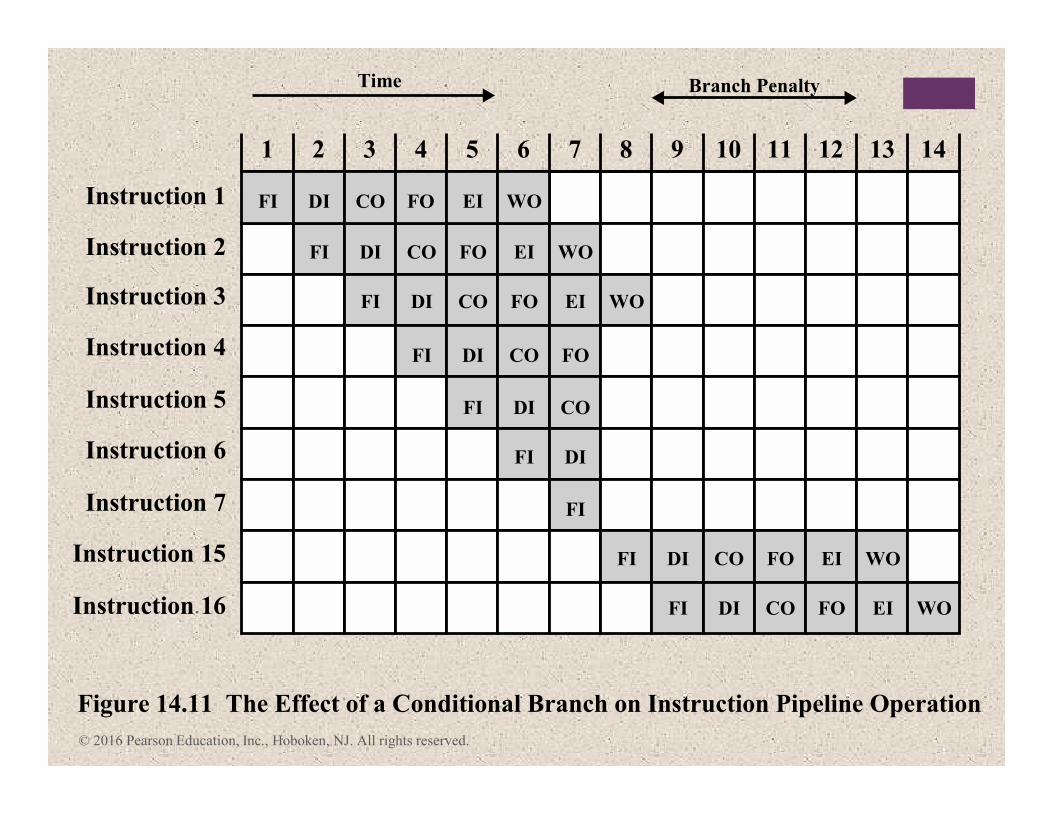
Figure 14.11 The Effect of a Conditional Branch on Instruction Pipeline Operation
2 3 4 5 6 7 8 9 10
Branch Penalty
11 12 13 14
FI DI CO FO EI WO
FI DI CO FO EI WO
FI DI CO FO EI WO
FI DI CO FO
FI DI CO
FI DI
FI
FI DI CO FO EI WO
FI DI CO FO EI WO
© 2016 Pearson Education, Inc., Hoboken, NJ. All rights reserved.
NoYes
Yes
No
FI
DI
CO
FO
EI
WO
Calculate
Operands
Fetch
Instruction
Decode
Instruction
Uncon-
ditional
Branch?
Branchor
Inter-rupt?
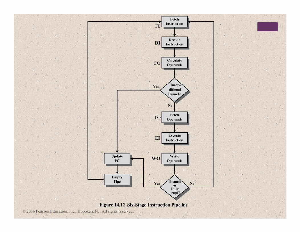
Figure 14.12 Six-Stage Instruction Pipeline
Write
Operands
Fetch
Operands
Execute
Instruction
Update
PC
Empty
Pipe
© 2016 Pearson Education, Inc., Hoboken, NJ. All rights reserved.
I16
I16
I16
I16
I16
I16
FI DI CO FO EI WO
I11
I2 I12
I3 I2 I13
I4 I3 I2 I14
I5 I4 I3 I2 I1
I6 I5 I4 I3 I2 I1
I7 I6 I5 I4 I3 I2
I8 I7 I6 I5 I4 I3
I9 I8 I7 I6 I5 I4
I9 I8 I7 I6 I5
I9 I8 I7 I6
I9 I8 I7
I9 I8
I9
5
6
7
8
9
10
11
12
13
14
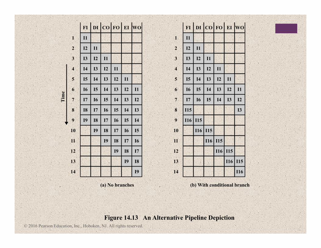
Figure 14.13 An Alternative Pipeline Depiction
(a) No branches
FI DI CO FO EI WO
I11
I2 I12
I3 I2 I13
I4 I3 I2 I14
I5 I4 I3 I2 I1
I6 I5 I4 I3 I2 I1
I7 I6 I5 I4 I3 I2
I15
I15
I15
I15
I15
I15
I3
5
6
7
8
9
10
11
12
13
14
(b) With conditional branch
Tim
e
© 2016 Pearson Education, Inc., Hoboken, NJ. All rights reserved.
1
0
2
4
6
8
10
12
0 5 10 15 20
0
2
4
6
8
10
12
14
2 4 8
Number of instructions (log scale)
(a)
Sp
eed
up
facto
rS
pee
du
p f
acto
r
Number of stages
(b)
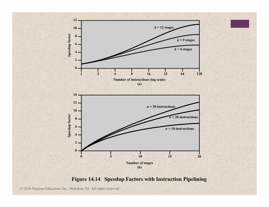
Figure 14.14 Speedup Factors with Instruction Pipelining
16
k = 6 stages
n = 10 instructions
n = 20 instructions
n = 30 instructions
k = 9 stages
k = 12 stages
32 64 128
Pipeline Hazards
Occur when the pipeline, or some
portion of the pipeline, must stall because conditions
do not permit continued execution
Also referred to as a pipeline bubble
There are three types of hazards:
• Resource
• Data
• Control
© 2016 Pearson Education, Inc., Hoboken, NJ. All rights reserved.

© 2016 Pearson Education, Inc., Hoboken, NJ. All rights reserved.
1
I1
Clock cycle
(a) Five-stage pipeline, ideal case
Inst
rutc
ion
FI
I2
I3
I4
Figure 14.15 Example of Resource Hazard
2 3 4 5 6 7 8 9
DI FO EI WO
FI DI FO EI WO
FI DI FO EI WO
FI DI FO EI WO
1
I1
Clock cycle
(b) I1 source operand in memory
Inst
rutc
ion
FI
I2
I3
I4
2 3 4 5 6 7 8 9
DI FO EI WO
FI DI FO EI WO
FIIdle DI FO EI WO
FI DI FO EI WO
© 2016 Pearson Education, Inc., Hoboken, NJ. All rights reserved.
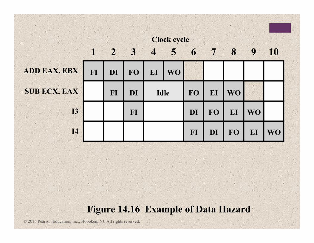
1
ADD EAX, EBX
Clock cycle
FI
SUB ECX, EAX
I3
I4
Figure 14.16 Example of Data Hazard
2 3 4 5 6 7 8 9 10
DI FO EI WO
FI DI Idle FO EI WO
FI DI FO EI WO
FI DI FO EI WO
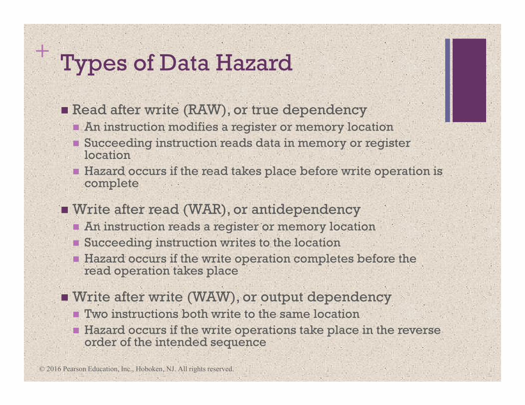
+Types of Data Hazard
� Read after write (RAW), or true dependency� An instruction modifies a register or memory location
� Succeeding instruction reads data in memory or register location
� Hazard occurs if the read takes place before write operation is complete
� Write after read (WAR), or antidependency� An instruction reads a register or memory location
� Succeeding instruction writes to the location
� Hazard occurs if the write operation completes before the read operation takes place
� Write after write (WAW), or output dependency� Two instructions both write to the same location
� Hazard occurs if the write operations take place in the reverse order of the intended sequence
© 2016 Pearson Education, Inc., Hoboken, NJ. All rights reserved.
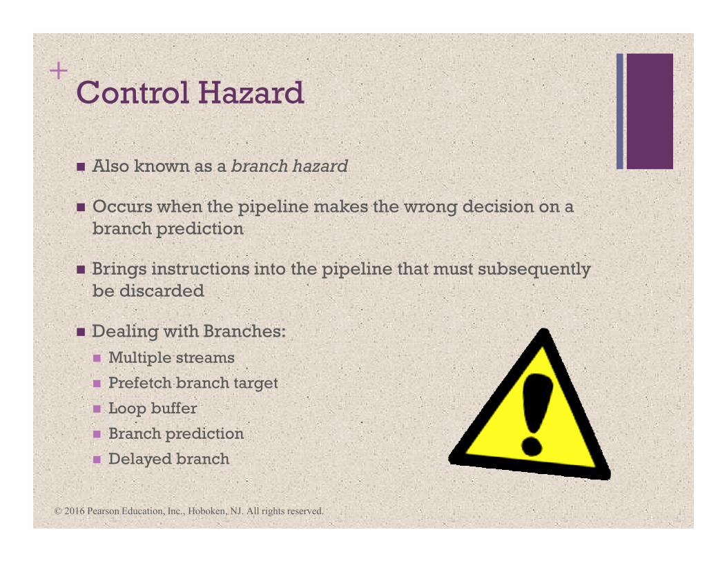
+Control Hazard
� Also known as a branch hazard
� Occurs when the pipeline makes the wrong decision on a
branch prediction
� Brings instructions into the pipeline that must subsequently
be discarded
� Dealing with Branches:
� Multiple streams
� Prefetch branch target
� Loop buffer
� Branch prediction
� Delayed branch
© 2016 Pearson Education, Inc., Hoboken, NJ. All rights reserved.
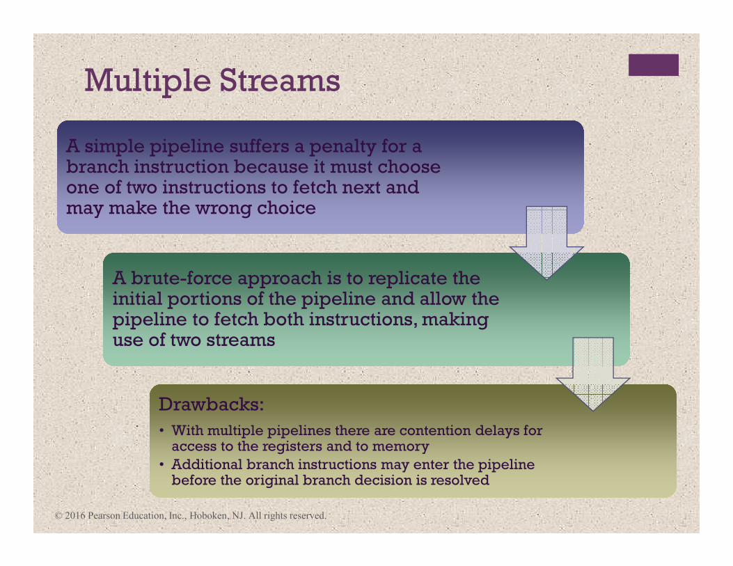
Multiple Streams
A simple pipeline suffers a penalty for a branch instruction because it must choose one of two instructions to fetch next and may make the wrong choice
A simple pipeline suffers a penalty for a branch instruction because it must choose one of two instructions to fetch next and may make the wrong choice
A brute-force approach is to replicate the initial portions of the pipeline and allow the pipeline to fetch both instructions, making use of two streams
A brute-force approach is to replicate the initial portions of the pipeline and allow the pipeline to fetch both instructions, making use of two streams
Drawbacks:
• With multiple pipelines there are contention delays for access to the registers and to memory
• Additional branch instructions may enter the pipeline before the original branch decision is resolved
Drawbacks:
• With multiple pipelines there are contention delays for access to the registers and to memory
• Additional branch instructions may enter the pipeline before the original branch decision is resolved
© 2016 Pearson Education, Inc., Hoboken, NJ. All rights reserved.
+
Prefetch Branch Target
� When a conditional branch is recognized, the
target of the branch is prefetched, in addition
to the instruction following the branch
� Target is then saved until the branch
instruction is executed
� If the branch is taken, the target has already
been prefetched
� IBM 360/91 uses this approach
© 2016 Pearson Education, Inc., Hoboken, NJ. All rights reserved.
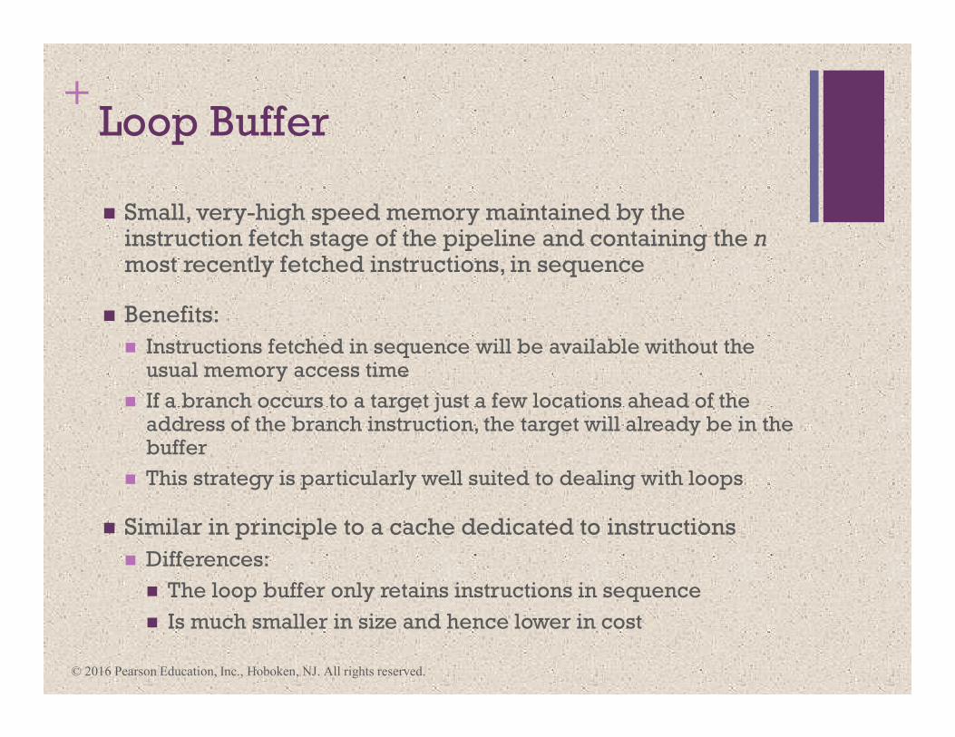
+Loop Buffer
� Small, very-high speed memory maintained by the instruction fetch stage of the pipeline and containing the n most recently fetched instructions, in sequence
� Benefits:
� Instructions fetched in sequence will be available without the usual memory access time
� If a branch occurs to a target just a few locations ahead of the address of the branch instruction, the target will already be in the buffer
� This strategy is particularly well suited to dealing with loops
� Similar in principle to a cache dedicated to instructions
� Differences:
� The loop buffer only retains instructions in sequence
� Is much smaller in size and hence lower in cost
© 2016 Pearson Education, Inc., Hoboken, NJ. All rights reserved.
© 2016 Pearson Education, Inc., Hoboken, NJ. All rights reserved.
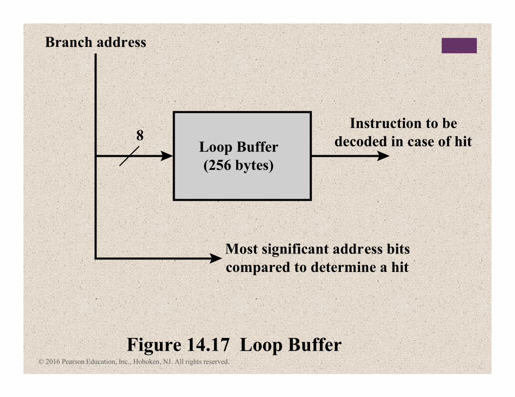
Loop Buffer
(256 bytes)
Branch address
8Instruction to be
decoded in case of hit
Most significant address bits
compared to determine a hit
Figure 14.17 Loop Buffer
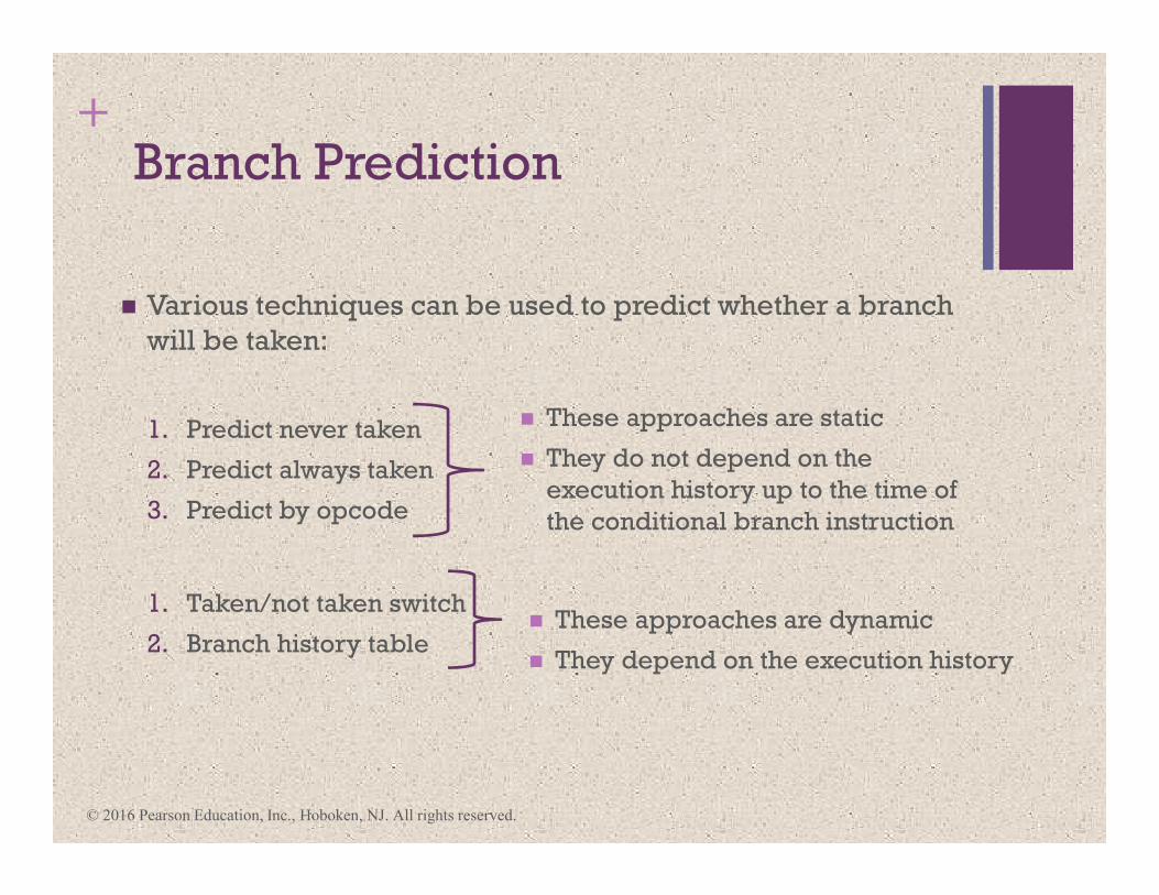
+Branch Prediction
� Various techniques can be used to predict whether a branch
will be taken:
1. Predict never taken
2. Predict always taken
3. Predict by opcode
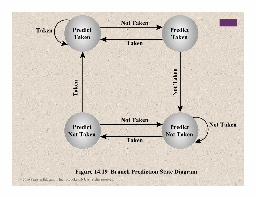
1. Taken/not taken switch
2. Branch history table
� These approaches are static
� They do not depend on the
execution history up to the time of
the conditional branch instruction
� These approaches are dynamic
� They depend on the execution history
© 2016 Pearson Education, Inc., Hoboken, NJ. All rights reserved.
© 2016 Pearson Education, Inc., Hoboken, NJ. All rights reserved.
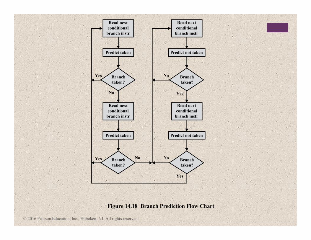
Figure 14.18 Branch Prediction Flow Chart
Yes
Yes
Predict taken
Read next
conditional
branch instr
Branch
taken?
Predict taken
Read next
conditional
branch instr
Branch
taken?
No Yes
Yes
Predict not taken
Read next
conditional
branch instr
Branch
taken?
Predict not taken
Read next
conditional
branch instr
Branch
taken?
No
NoNo
© 2016 Pearson Education, Inc., Hoboken, NJ. All rights reserved.
Figure 14.19 Branch Prediction State Diagram
Not TakenNot Taken
Not
Tak
en
Taken
Tak
en
Not Taken
Taken
Taken Predict
Taken
Predict
Taken
Predict
Not Taken
Predict
Not Taken
© 2016 Pearson Education, Inc., Hoboken, NJ. All rights reserved.
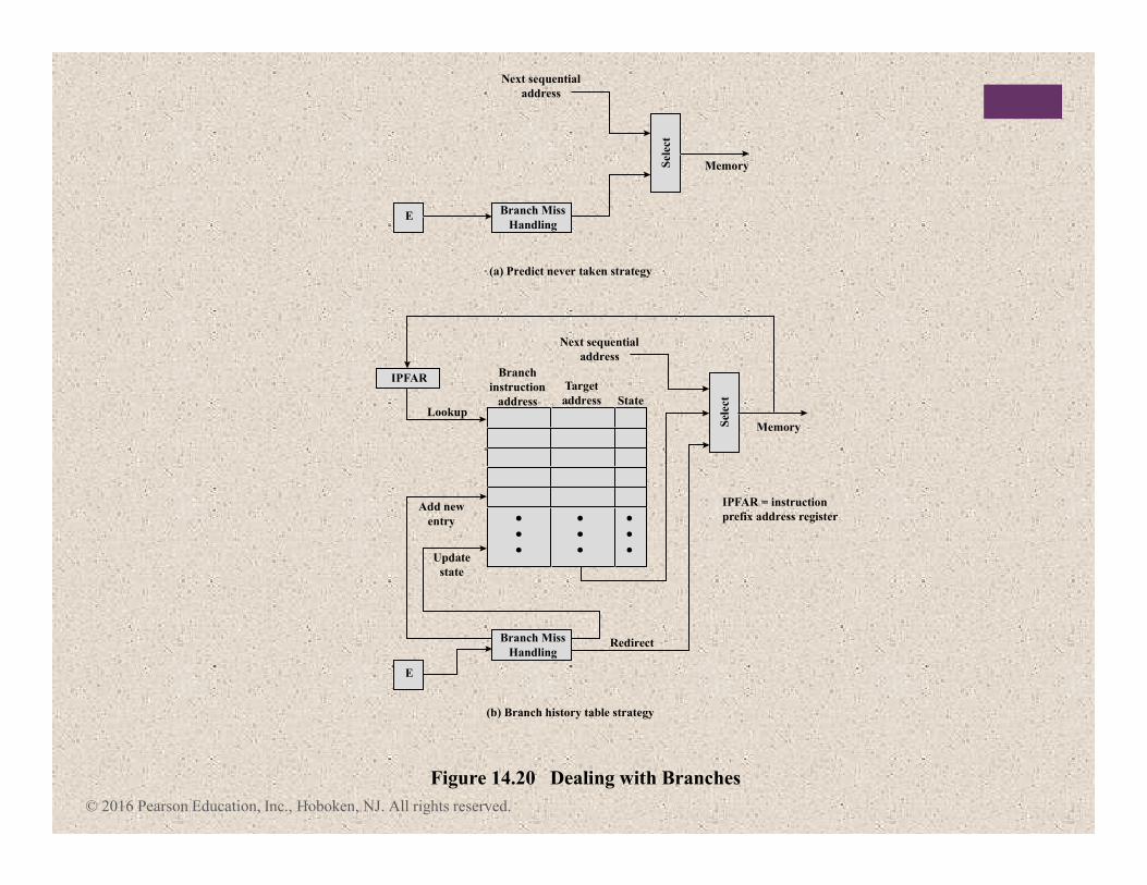
Branch Miss
Handling
Sel
ect
E
Branch Miss
Handling
E
Memory
Sel
ect
Memory
IPFAR
IPFAR = instruction
prefix address register
Lookup
Update
state
Add new
entry
Redirect
Branch
instruction
address
Target
address State
Next sequential
address
Next sequential
address
(a) Predict never taken strategy
(b) Branch history table strategy
Figure 14.20 Dealing with Branches
© 2016 Pearson Education, Inc., Hoboken, NJ. All rights reserved.
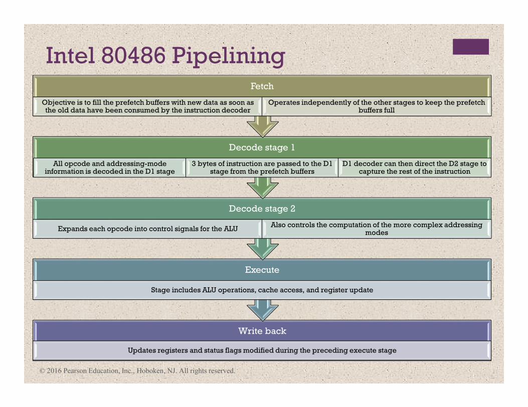
Intel 80486 Pipelining
Write back
Updates registers and status flags modified during the preceding execute stage
Execute
Stage includes ALU operations, cache access, and register update
Decode stage 2
Expands each opcode into control signals for the ALUAlso controls the computation of the more complex addressing
modes
Decode stage 1
All opcode and addressing-mode information is decoded in the D1 stage
3 bytes of instruction are passed to the D1 stage from the prefetch buffers
D1 decoder can then direct the D2 stage to capture the rest of the instruction
Fetch
Objective is to fill the prefetch buffers with new data as soon as the old data have been consumed by the instruction decoder
Operates independently of the other stages to keep the prefetch buffers full
© 2016 Pearson Education, Inc., Hoboken, NJ. All rights reserved.
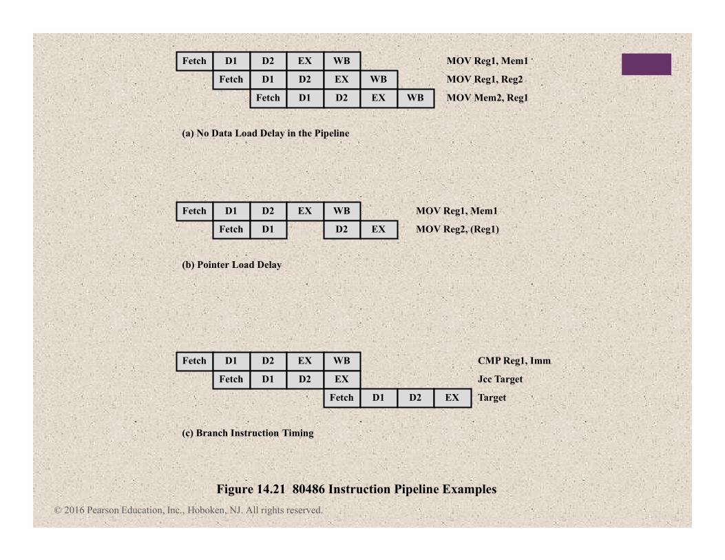
Fetch D1 D2 EX WB
Fetch D1 D2 EX WB
Fetch D1 D2 EX WB MOV Mem2, Reg1
(a) No Data Load Delay in the Pipeline
MOV Reg1, Reg2
MOV Reg1, Mem1
Fetch D1 D2 EX WB
Fetch D1 D2 EX
Fetch D1 D2 EX Target
(c) Branch Instruction Timing
Figure 14.21 80486 Instruction Pipeline Examples
Jcc Target
CMP Reg1, Imm
Fetch D1 D2 EX WB
Fetch D1 D2 EX
(b) Pointer Load Delay
MOV Reg2, (Reg1)
MOV Reg1, Mem1
© 2016 Pearson Education, Inc., Hoboken, NJ. All rights reserved.
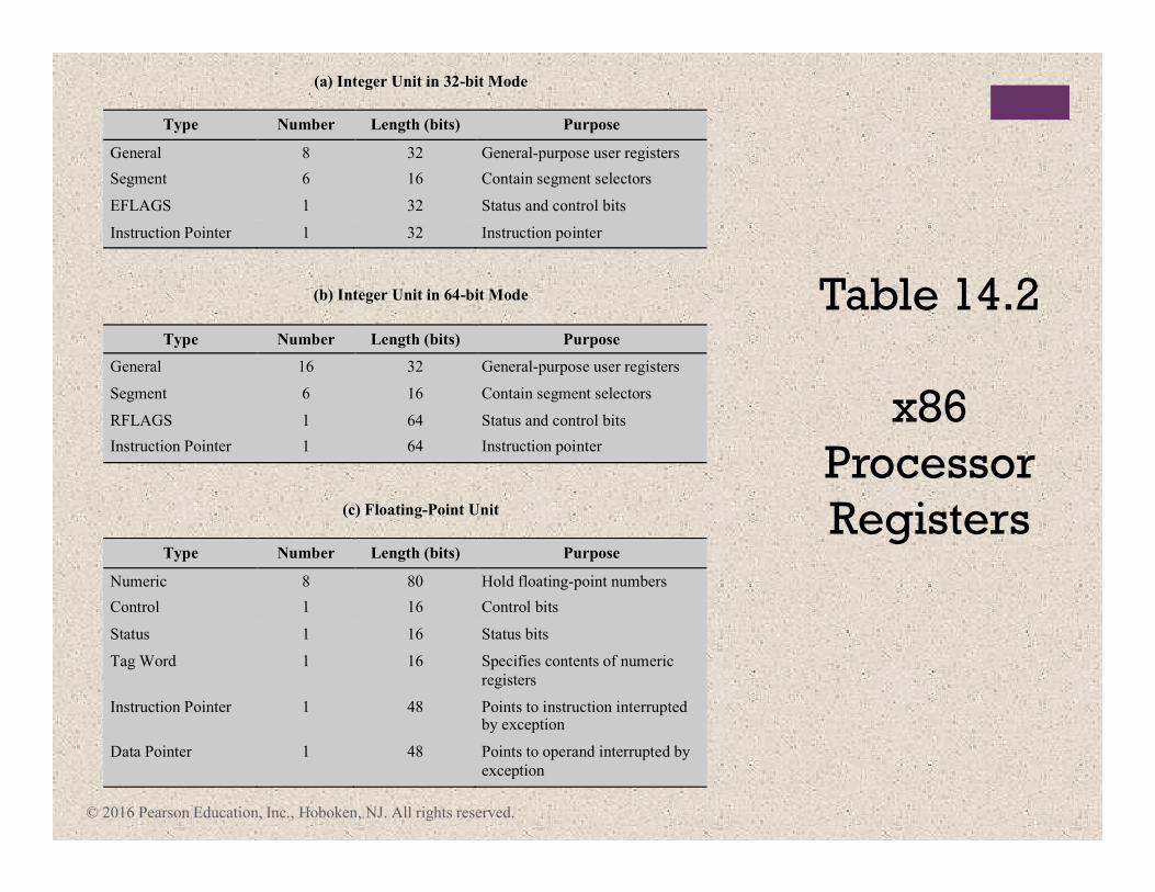
(a) Integer Unit in 32-bit Mode
Type Number Length (bits) Purpose
General 8 32 General-purpose user registers
Segment 6 16 Contain segment selectors
EFLAGS 1 32 Status and control bits
Instruction Pointer 1 32 Instruction pointer
(b) Integer Unit in 64-bit Mode
Type Number Length (bits) Purpose
General 16 32 General-purpose user registers
Segment 6 16 Contain segment selectors
RFLAGS 1 64 Status and control bits
Instruction Pointer 1 64 Instruction pointer
(c) Floating-Point Unit
Type Number Length (bits) Purpose
Numeric 8 80 Hold floating-point numbers
Control 1 16 Control bits
Status 1 16 Status bits
Tag Word 1 16 Specifies contents of numeric
registers
Instruction Pointer 1 48 Points to instruction interrupted by exception
Data Pointer 1 48 Points to operand interrupted by
exception
Table 14.2
x86
Processor
Registers
© 2016 Pearson Education, Inc., Hoboken, NJ. All rights reserved.
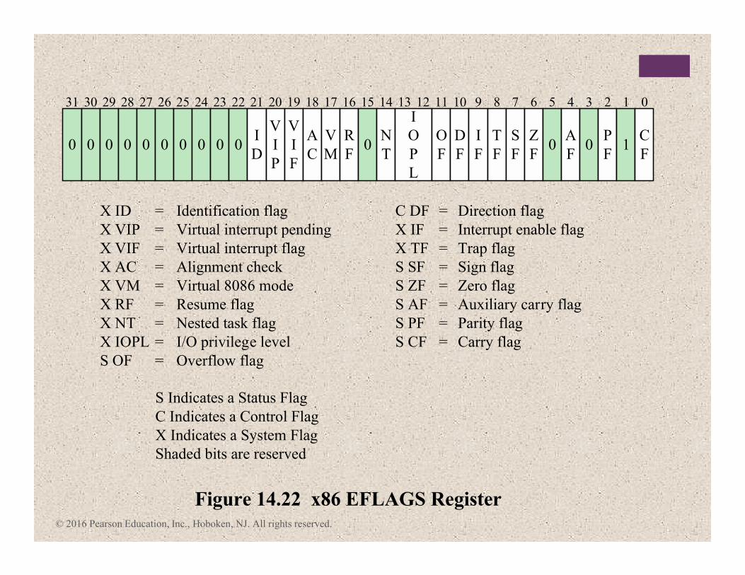
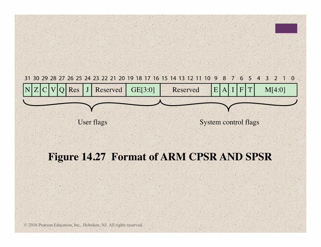
Figure 14.22 x86 EFLAGS Register
X ID = Identification flag
X VIP = Virtual interrupt pending
X VIF = Virtual interrupt flag
X AC = Alignment check
X VM = Virtual 8086 mode
X RF = Resume flag
X NT = Nested task flag
X IOPL = I/O privilege level
S OF = Overflow flag
C DF = Direction flag
X IF = Interrupt enable flag
X TF = Trap flag
S SF = Sign flag
S ZF = Zero flag
S AF = Auxiliary carry flag
S PF = Parity flag
S CF = Carry flag
31 30 29 28 27 26 25 24 23 22 21 20 19 18 17 16 15 14 13 12 11 10 9 8 7 6 5 4 3 2 1
0 0 0 0 0 0 0 0 0 0I
D
V
I
P
V
I
F
A
C
V
M
R
F0
N
T
I
O
P
L
O
F
D
F
I
F
T
F
S
F
Z
F0
A
F0
P
F1
C
F
0
S Indicates a Status Flag
C Indicates a Control Flag
X Indicates a System Flag
Shaded bits are reserved
© 2016 Pearson Education, Inc., Hoboken, NJ. All rights reserved.
© 2016 Pearson Education, Inc., Hoboken, NJ. All rights reserved.
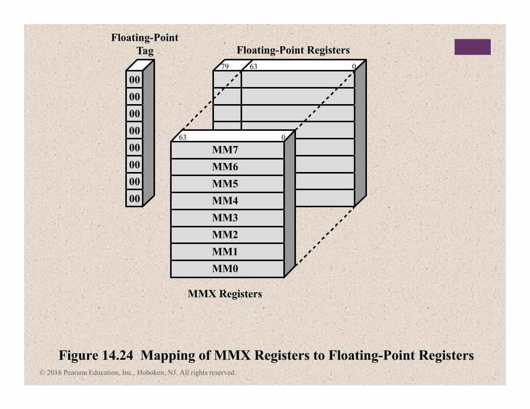
079 63
63 0
MM0
00
00
00
00
00
00
00
00
MMX Registers
Figure 14.24 Mapping of MMX Registers to Floating-Point Registers
Floating-Point Registers
Floating-Point
Tag
MM1
MM2
MM3
MM4
MM5
MM6
MM7
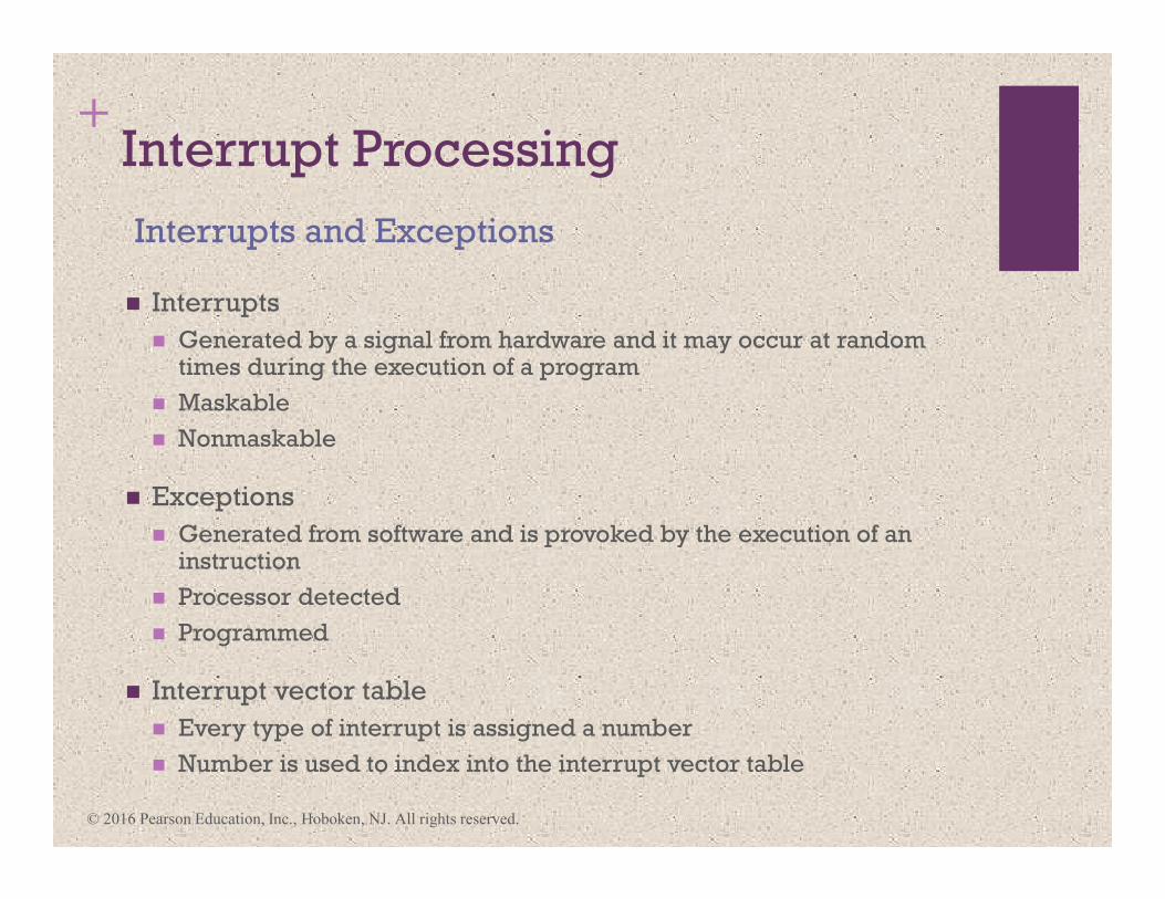
+Interrupt Processing
� Interrupts
� Generated by a signal from hardware and it may occur at random times during the execution of a program
� Maskable
� Nonmaskable
� Exceptions
� Generated from software and is provoked by the execution of an instruction
� Processor detected
� Programmed
� Interrupt vector table
� Every type of interrupt is assigned a number
� Number is used to index into the interrupt vector table
Interrupts and Exceptions
© 2016 Pearson Education, Inc., Hoboken, NJ. All rights reserved.
© 2016 Pearson Education, Inc., Hoboken, NJ. All rights reserved.
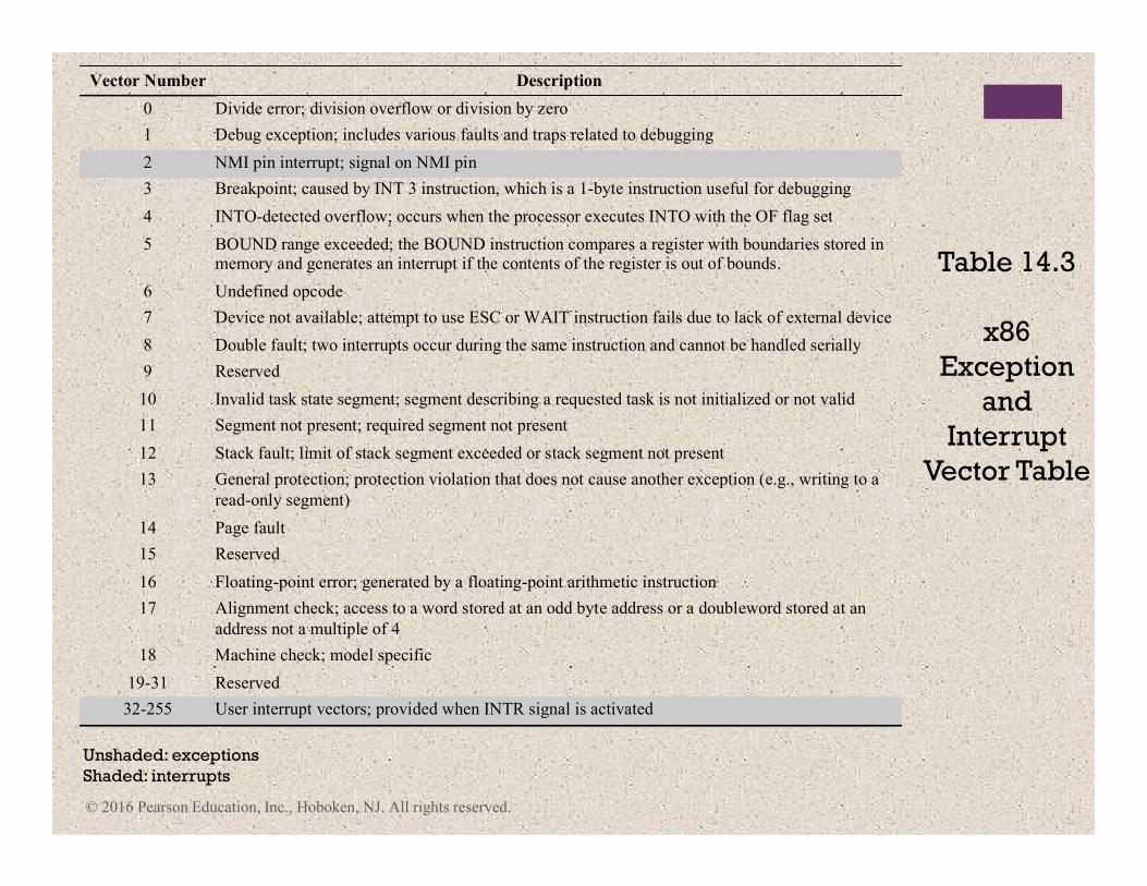
Vector Number Description
0 Divide error; division overflow or division by zero
1 Debug exception; includes various faults and traps related to debugging
2 NMI pin interrupt; signal on NMI pin
3 Breakpoint; caused by INT 3 instruction, which is a 1-byte instruction useful for debugging
4 INTO-detected overflow; occurs when the processor executes INTO with the OF flag set
5 BOUND range exceeded; the BOUND instruction compares a register with boundaries stored in memory and generates an interrupt if the contents of the register is out of bounds.
6 Undefined opcode
7 Device not available; attempt to use ESC or WAIT instruction fails due to lack of external device
8 Double fault; two interrupts occur during the same instruction and cannot be handled serially
9 Reserved
10 Invalid task state segment; segment describing a requested task is not initialized or not valid
11 Segment not present; required segment not present
12 Stack fault; limit of stack segment exceeded or stack segment not present
13 General protection; protection violation that does not cause another exception (e.g., writing to a
read-only segment)
14 Page fault
15 Reserved
16 Floating-point error; generated by a floating-point arithmetic instruction
17 Alignment check; access to a word stored at an odd byte address or a doubleword stored at an
address not a multiple of 4
18 Machine check; model specific
19-31 Reserved
32-255 User interrupt vectors; provided when INTR signal is activated
Unshaded: exceptions
Shaded: interrupts
Table 14.3
x86
Exception
and
Interrupt
Vector Table
+ The ARM Processor
� Moderate array of uniform registers
� A load/store model of data processing in which operations only perform on operands in registers and not directly in memory
� A uniform fixed-length instruction of 32 bits for the standard set and 16 bits for the Thumb instruction set
� Separate arithmetic logic unit (ALU) and shifter units
� A small number of addressing modes with all load/store addresses determined from registers and instruction fields
� Auto-increment and auto-decrement addressing modes are used to improve the operation of program loops
� Conditional execution of instructions minimizes the need for conditional branch instructions, thereby improving pipeline efficiency, because pipeline flushing is reduced
ARM is primarily a RISC system with the following
attributes:
© 2016 Pearson Education, Inc., Hoboken, NJ. All rights reserved.
© 2016 Pearson Education, Inc., Hoboken, NJ. All rights reserved.
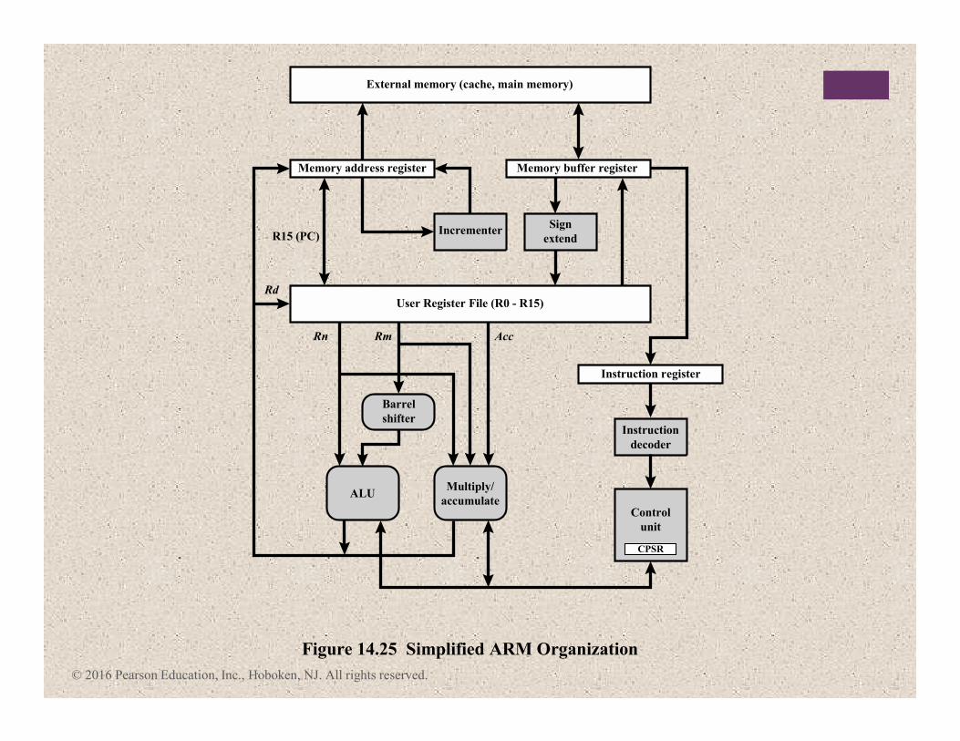
Memory address register
Incrementer
Barrel
shifter
Multiply/
accumulate
Figure 14.25 Simplified ARM Organization
ALU
R15 (PC)
Rn Rm
Rd
Acc
Sign
extend
User Register File (R0 - R15)
External memory (cache, main memory)
Memory buffer register
Instruction register
Control
unit
Instruction
decoder
CPSR
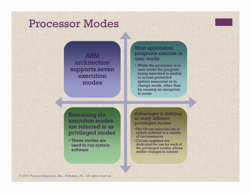
Processor Modes
ARM architecture
supports seven execution
modes
ARM architecture
supports seven execution
modes
Most application programs execute in user mode
• While the processor is in user mode the program being executed is unable to access protected system resources or to change mode, other than by causing an exception to occur
Most application programs execute in user mode
• While the processor is in user mode the program being executed is unable to access protected system resources or to change mode, other than by causing an exception to occur
Remaining six execution modes are referred to as privileged modes
• These modes are used to run system software
Remaining six execution modes are referred to as privileged modes
• These modes are used to run system software
Advantages to defining so many different privileged modes
•The OS can tailor the use of system software to a variety of circumstances
•Certain registers are dedicated for use for each of the privileged modes, allows swifter changes in context
Advantages to defining so many different privileged modes
•The OS can tailor the use of system software to a variety of circumstances
•Certain registers are dedicated for use for each of the privileged modes, allows swifter changes in context
© 2016 Pearson Education, Inc., Hoboken, NJ. All rights reserved.
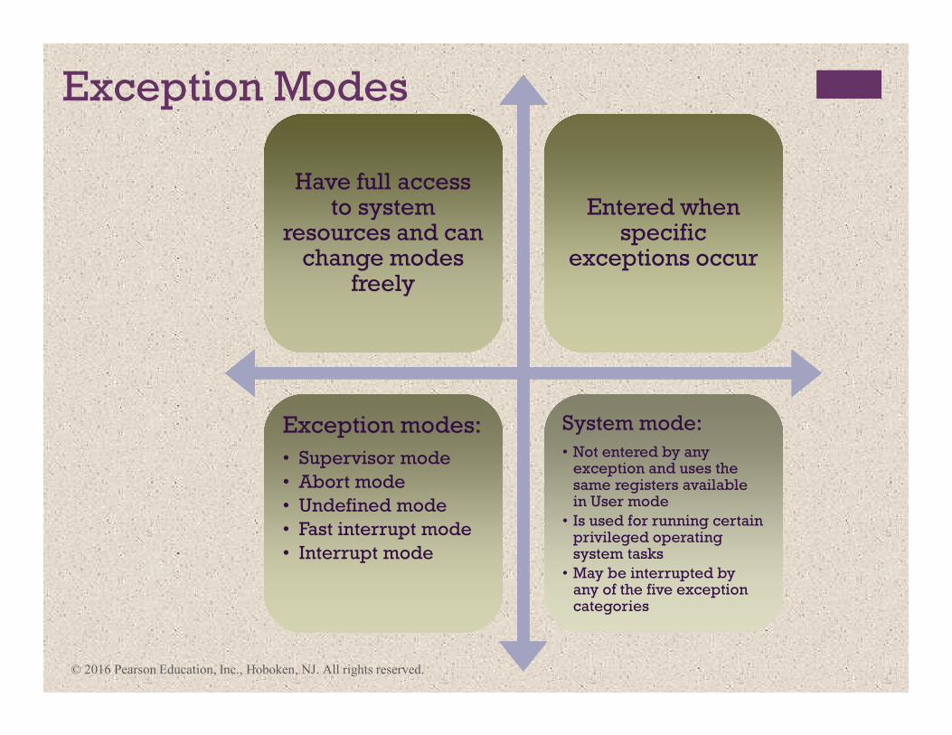
Exception Modes
Have full access to system
resources and can change modes
freely
Have full access to system
resources and can change modes
freely
Entered when specific
exceptions occur
Entered when specific
exceptions occur
Exception modes:
• Supervisor mode
• Abort mode
• Undefined mode
• Fast interrupt mode
• Interrupt mode
Exception modes:
• Supervisor mode
• Abort mode
• Undefined mode
• Fast interrupt mode
• Interrupt mode
System mode:
• Not entered by any exception and uses the same registers available in User mode
• Is used for running certain privileged operating system tasks
• May be interrupted by any of the five exception categories
System mode:
• Not entered by any exception and uses the same registers available in User mode
• Is used for running certain privileged operating system tasks
• May be interrupted by any of the five exception categories
© 2016 Pearson Education, Inc., Hoboken, NJ. All rights reserved.
© 2016 Pearson Education, Inc., Hoboken, NJ. All rights reserved.
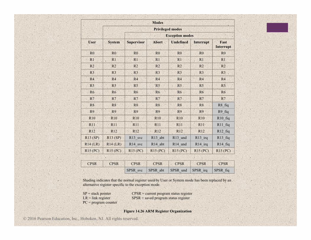
Modes
Privileged modes
Exception modes
User System Supervisor Abort Undefined Interrupt Fast
Interrupt
R0 R0 R0 R0 R0 R0 R0
R1 R1 R1 R1 R1 R1 R1
R2 R2 R2 R2 R2 R2 R2
R3 R3 R3 R3 R3 R3 R3
R4 R4 R4 R4 R4 R4 R4
R5 R5 R5 R5 R5 R5 R5
R6 R6 R6 R6 R6 R6 R6
R7 R7 R7 R7 R7 R7 R7
R8 R8 R8 R8 R8 R8 R8_fiq
R9 R9 R9 R9 R9 R9 R9_fiq
R10 R10 R10 R10 R10 R10 R10_fiq
R11 R11 R11 R11 R11 R11 R11_fiq
R12 R12 R12 R12 R12 R12 R12_fiq
R13 (SP) R13 (SP) R13_svc R13_abt R13_und R13_irq R13_fiq
R14 (LR) R14 (LR) R14_svc R14_abt R14_und R14_irq R14_fiq
R15 (PC) R15 (PC) R15 (PC) R15 (PC) R15 (PC) R15 (PC) R15 (PC)
CPSR CPSR CPSR CPSR CPSR CPSR CPSR
SPSR_svc SPSR_abt SPSR_und SPSR_irq SPSR_fiq
Shading indicates that the normal register used by User or System mode has been replaced by an
alternative register specific to the exception mode.
SP = stack pointer CPSR = current program status register
LR = link register SPSR = saved program status register
PC = program counter
Figure 14.26 ARM Register Organization
© 2016 Pearson Education, Inc., Hoboken, NJ. All rights reserved.
© 2016 Pearson Education, Inc., Hoboken, NJ. All rights reserved.
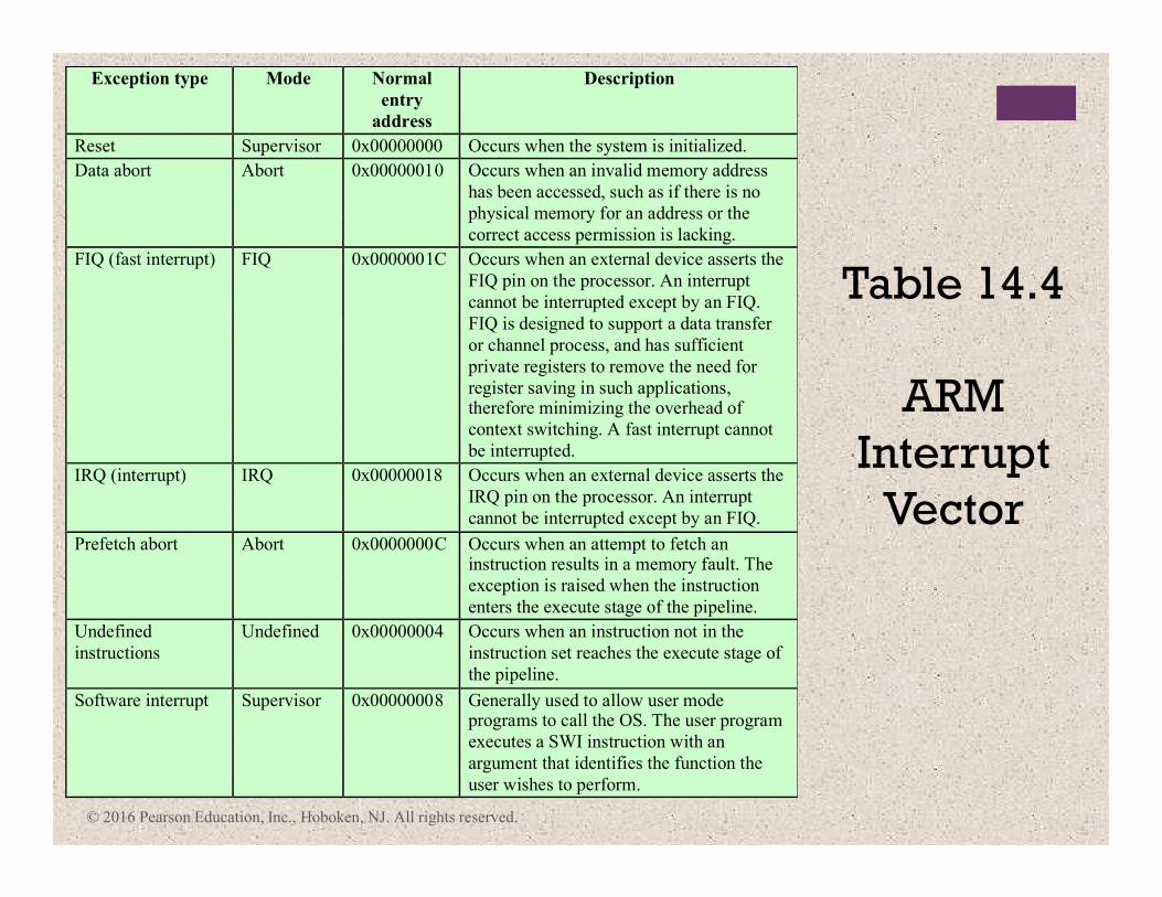
Exception type Mode Normal
entry
address
Description
Reset Supervisor 0x00000000 Occurs when the system is initialized.
Data abort Abort 0x00000010 Occurs when an invalid memory address
has been accessed, such as if there is no
physical memory for an address or the
correct access permission is lacking.
FIQ (fast interrupt) FIQ 0x0000001C Occurs when an external device asserts the
FIQ pin on the processor. An interrupt
cannot be interrupted except by an FIQ.
FIQ is designed to support a data transfer
or channel process, and has sufficient
private registers to remove the need for
register saving in such applications, therefore minimizing the overhead of
context switching. A fast interrupt cannot
be interrupted.
IRQ (interrupt) IRQ 0x00000018 Occurs when an external device asserts the
IRQ pin on the processor. An interrupt
cannot be interrupted except by an FIQ.
Prefetch abort Abort 0x0000000C Occurs when an attempt to fetch an instruction results in a memory fault. The
exception is raised when the instruction
enters the execute stage of the pipeline.
Undefined
instructions
Undefined 0x00000004 Occurs when an instruction not in the
instruction set reaches the execute stage of
the pipeline.
Software interrupt Supervisor 0x00000008 Generally used to allow user mode programs to call the OS. The user program
executes a SWI instruction with an
argument that identifies the function the
user wishes to perform.
Table 14.4
ARM
Interrupt
Vector
+ Summary
� Processor organization
� Register organization
� User-visible registers
� Control and status registers
� Instruction cycle
� The indirect cycle
� Data flow
� The x86 processor family
� Register organization
� Interrupt processing
� Instruction pipelining
� Pipelining strategy
� Pipeline performance
� Pipeline hazards
� Dealing with branches
� Intel 80486 pipelining
� The Arm processor
� Processor organization
� Processor modes
� Register organization
� Interrupt processing
Chapter 14
Processor Structure
and Function
© 2016 Pearson Education, Inc., Hoboken, NJ. All rights reserved.