Embed Size (px)
Citation preview
Edition 06.2010Page
Winding technology, pneumaticallyactuated tension brakes
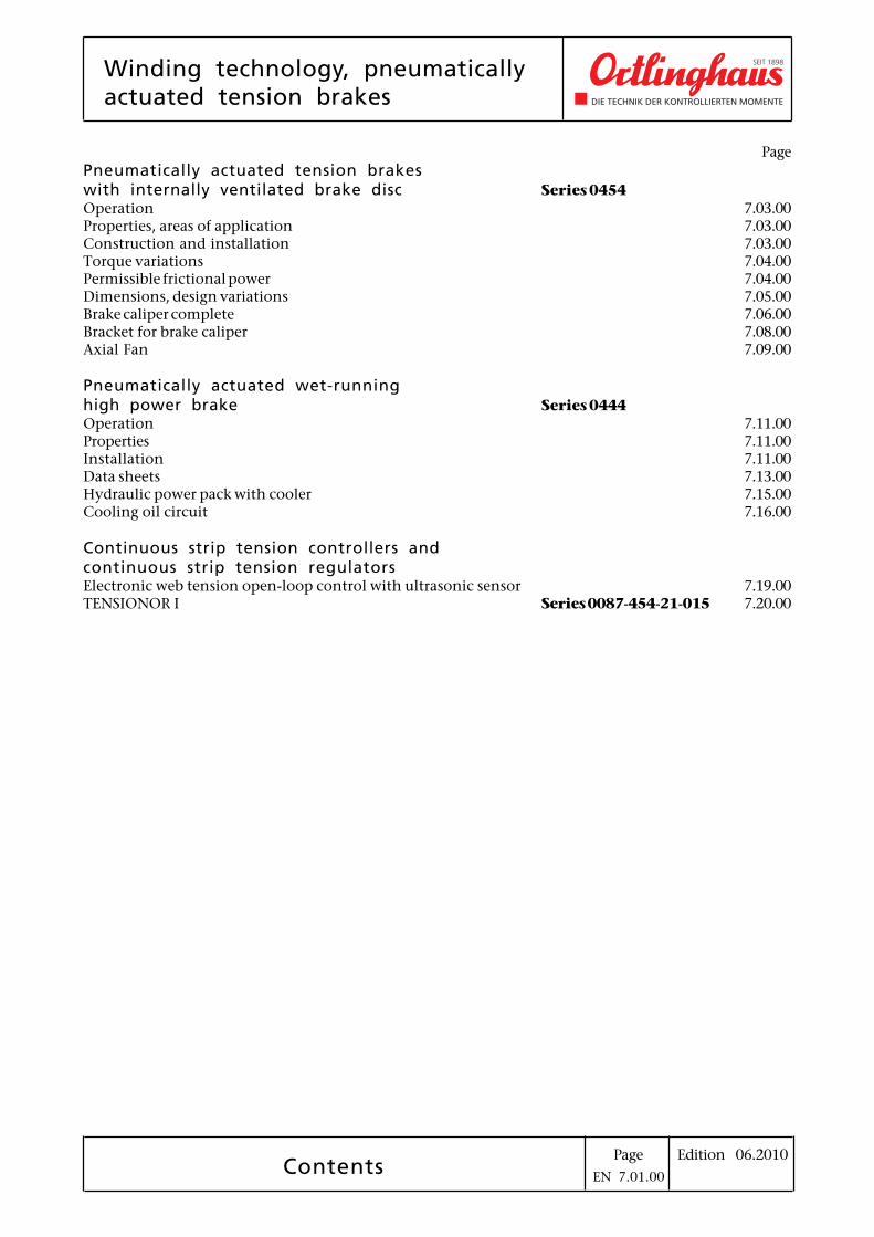
Contents
Page
Pneumatically actuated tension brakeswith internally ventilated brake disc Series 0454
Operation 7.03.00Properties, areas of application 7.03.00Construction and installation 7.03.00Torque variations 7.04.00Permissible frictional power 7.04.00Dimensions, design variations 7.05.00Brake caliper complete 7.06.00Bracket for brake caliper 7.08.00Axial Fan 7.09.00
Pneumatically actuated wet-runninghigh power brake Series 0444
Operation 7.11.00Properties 7.11.00Installation 7.11.00Data sheets 7.13.00Hydraulic power pack with cooler 7.15.00Cooling oil circuit 7.16.00
Continuous strip tension controllers andcontinuous strip tension regulatorsElectronic web tension open-loop control with ultrasonic sensor 7.19.00TENSIONOR I Series 0087-454-21-015 7.20.00
EN 7.01.00

Edition 06.2010PageSeries 0454
Pneumatically actuated tension brakeswith internally ventilated brake disc
Tension brake
Properties, areas of applicationThe brakes are mainly used for continuous brakingprocesses predominantly on unwinding equipment.In controlled or regulated processes the brake is theactuator.In this area the Ortlinghaus tension brake fulfilsthe following requirements
• sensitive response, low hysteresis
• facility to switch in or out each caliper
• good heat dissipation
• quiet running
Ortlinghaus tension brake, the importantfeatures are:
• low friction actuation unit with diaphragm, lowvolumetric capacity
• modular construction
• internally vented brake disc
• splined internal drive hub
• dual contact pressure on the friction linings
For the control of the brake, Ortlinghaus con-trol units (Tensionor) for web tension controlon unwinding equipment are available.
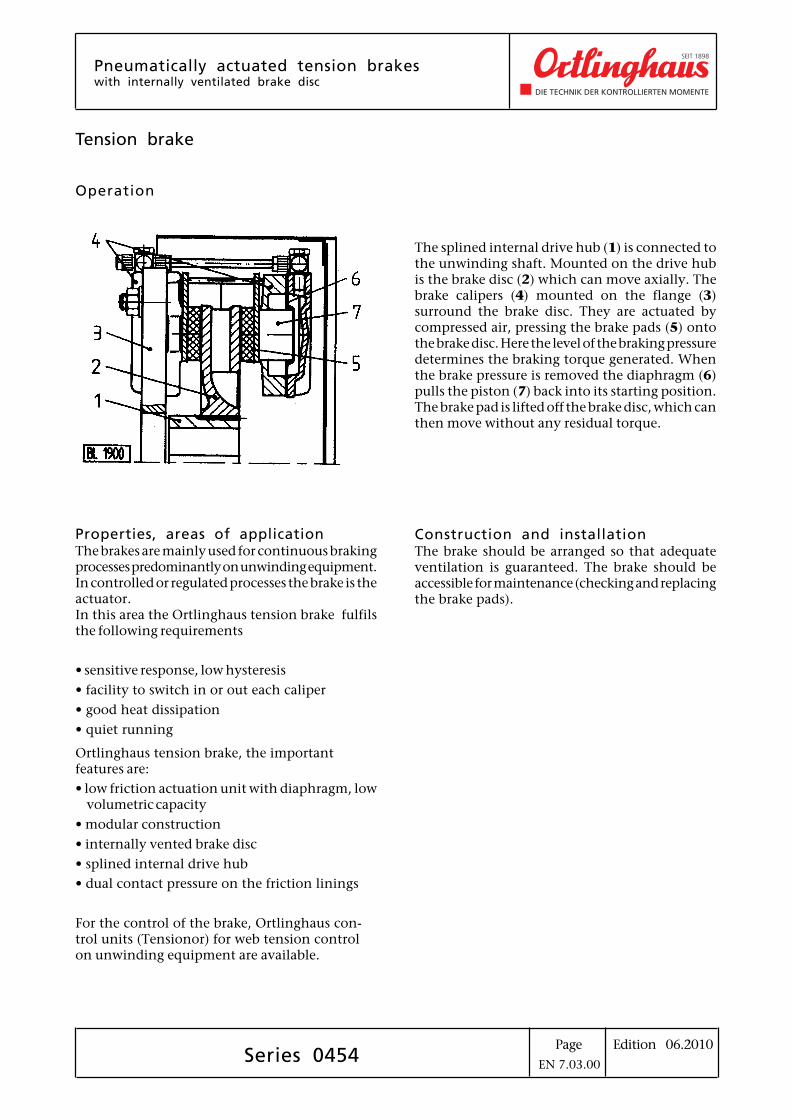
Operation
The splined internal drive hub (1) is connected tothe unwinding shaft. Mounted on the drive hubis the brake disc (2) which can move axially. Thebrake calipers (4) mounted on the flange (3)surround the brake disc. They are actuated bycompressed air, pressing the brake pads (5) ontothe brake disc. Here the level of the braking pressuredetermines the braking torque generated. Whenthe brake pressure is removed the diaphragm (6)pulls the piston (7) back into its starting position.The brake pad is lifted off the brake disc, which canthen move without any residual torque.
Construction and installationThe brake should be arranged so that adequateventilation is guaranteed. The brake should beaccessible for maintenance (checking and replacingthe brake pads).
EN 7.03.00
Edition 06.2010PageSeries 0454
Pneumatically actuated tension brakeswith internally ventilated brake disc
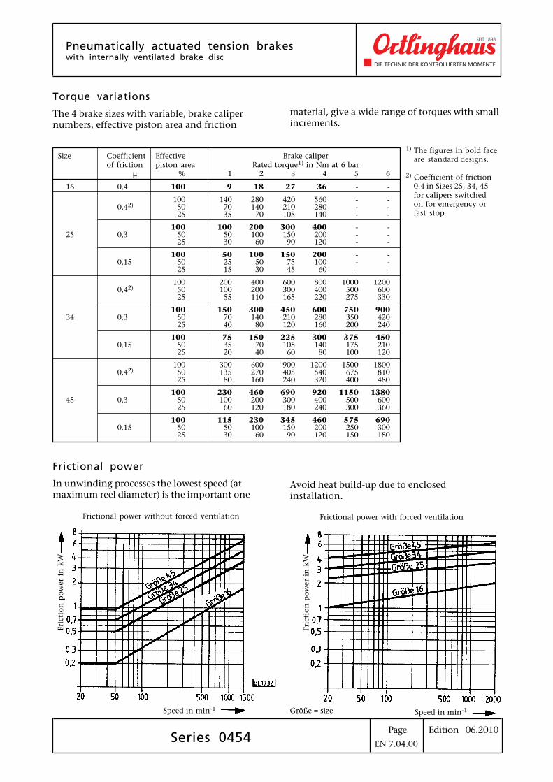
Size Coefficient Effective Brake caliperof friction piston area Rated torque1) in Nm at 6 bar
µ % 1 2 3 4 5 6
16 0,4 100 9 18 27 36 - -
100 140 280 420 560 - -0,42) 50 70 140 210 280 - -
25 35 70 105 140 - -
100 100 200 300 400 - -25 0,3 50 50 100 150 200 - -
25 30 60 90 120 - -
100 50 100 150 200 - -0,15 50 25 50 75 100 - -
25 15 30 45 60 - -
100 200 400 600 800 1000 12000,42) 50 100 200 300 400 500 600
25 55 110 165 220 275 330
100 150 300 450 600 750 90034 0,3 50 70 140 210 280 350 420
25 40 80 120 160 200 240
100 75 150 225 300 375 4500,15 50 35 70 105 140 175 210
25 20 40 60 80 100 120
100 300 600 900 1200 1500 18000,42) 50 135 270 405 540 675 810
25 80 160 240 320 400 480
100 230 460 690 920 1150 138045 0,3 50 100 200 300 400 500 600
25 60 120 180 240 300 360
100 115 230 345 460 575 6900,15 50 50 100 150 200 250 300
25 30 60 90 120 150 180
Torque variations
The 4 brake sizes with variable, brake calipernumbers, effective piston area and friction
1) The figures in bold faceare standard designs.
2) Coefficient of friction0.4 in Sizes 25, 34, 45for calipers switchedon for emergency orfast stop.
material, give a wide range of torques with smallincrements.
Frictional power
In unwinding processes the lowest speed (atmaximum reel diameter) is the important one
Frictional power without forced ventilation
Speed in min-1
Fri
cti
on
po
wer
in k
W
Frictional power with forced ventilation
Speed in min-1
Fri
cti
on
po
wer
in k
W
Avoid heat build-up due to enclosedinstallation.
Größe = size
EN 7.04.00
Edition 06.2010Page
Design variations on request
Pneumatically actuated tension brakeswith internally ventilated brake disc
Series 0454
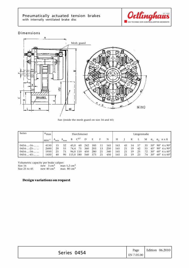
Dimensions
Mesh guard
Fan (inside the mesh guard on size 34 and 45)
Volumetric capacity per brake caliper:Size 16 new 3 cm3 max 5,2 cm3
Size 25 to 45 new 40 cm3 max 80 cm3
EN 7.05.00
Series nmax Durchmesser Längenmaße
min-1 Amin Amax B CH7 D E F N H J K L M α1 α2 n x ß
0454-...-16-... ... 4150 15 32 45,0 60 242 185 11 165 163 45 14 57 35 50° 90° 4 x 90°0454-...-25-... ... 2600 20 55 74,4 75 360 203 13 250 165 21 19 42 55 45° 90° 4 x 90°0454-...-34-... ... 1950 25 75 96,0 110 450 280 21 340 165 21 19 25 72 30° 60° 6 x 60°0454-...-45-... ... 1450 40 90 115,0 180 560 375 21 450 165 21 19 23 74 30° 60° 6 x 60°
Edition 06.2010Page
Effective area cm2 2,4
Swept new cm3 3,0volume max cm3 5,2
Operating min bar 0,1pressure max bar 6,0
Brake caliper complete
Series 0454
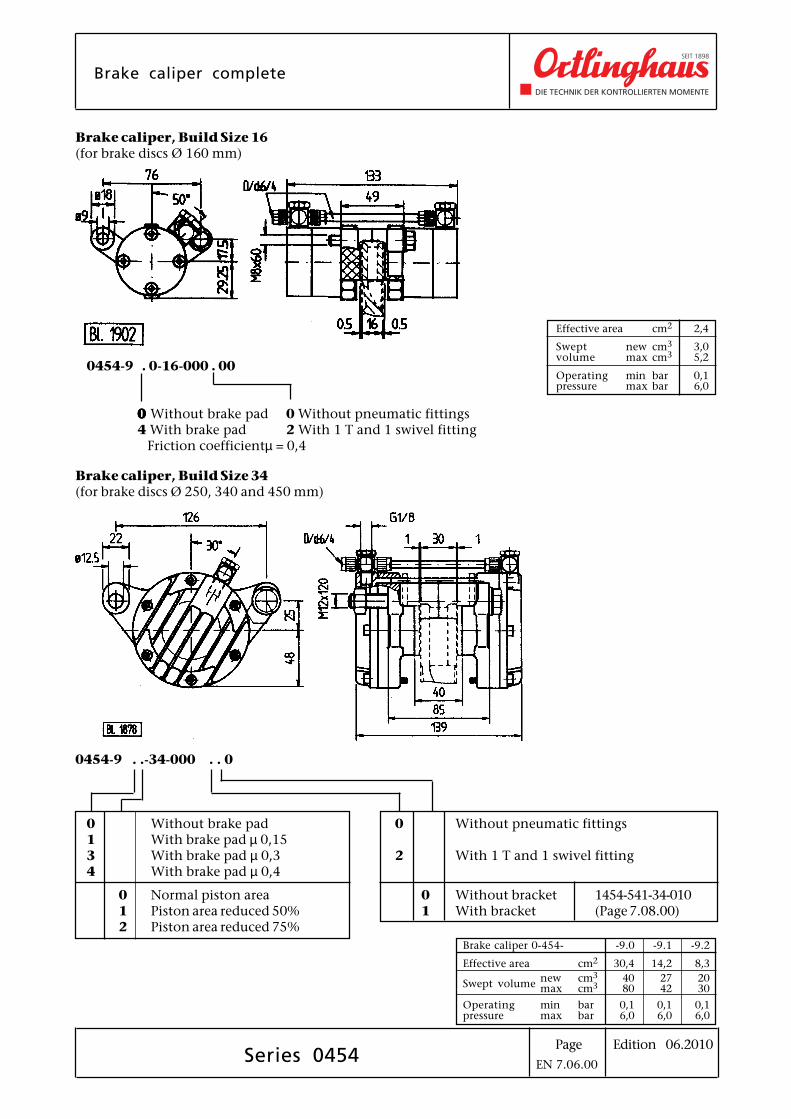
0454-9 . 0-16-000 . 00
00000 Without brake pad 0 Without pneumatic fittings4 With brake pad 2 With 1 T and 1 swivel fitting Friction coefficientµ = 0,4
0454-9 . .-34-000 . . 0
0 Without brake pad1 With brake pad µ 0,153 With brake pad µ 0,34 With brake pad µ 0,4
0 Normal piston area1 Piston area reduced 50%2 Piston area reduced 75%
Brake caliper 0-454- -9.0 -9.1 -9.2
Effective area cm2 30,4 14,2 8,3
Swept volumenew cm3 40 27 20max cm3 80 42 30
Operating min bar 0,1 0,1 0,1pressure max bar 6,0 6,0 6,0
Brake caliper, Build Size 16(for brake discs Ø 160 mm)
Brake caliper, Build Size 34(for brake discs Ø 250, 340 and 450 mm)
0 Without pneumatic fittings
2 With 1 T and 1 swivel fitting
0 Without bracket 1454-541-34-0101 With bracket (Page 7.08.00)
EN 7.06.00
Edition 06.2010Page
Brake caliper complete
Series 0454
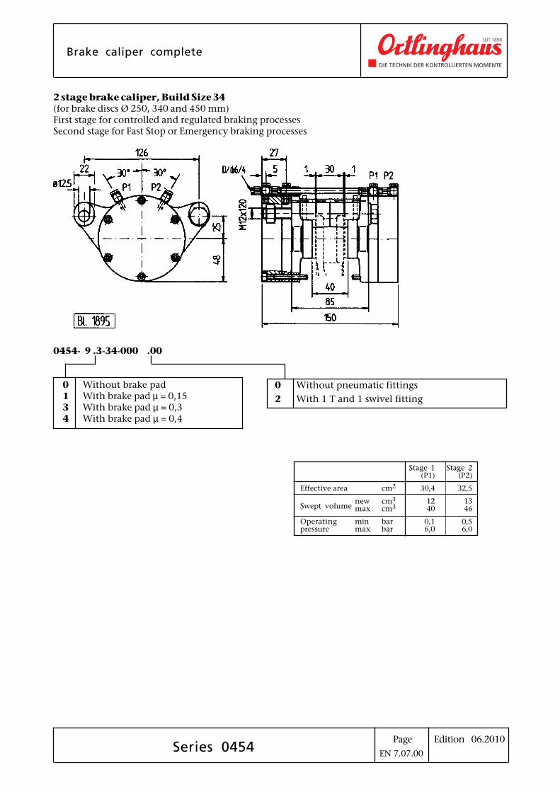
0454- 9 .3-34-000 .00
0 Without brake pad1 With brake pad µ = 0,153 With brake pad µ = 0,34 With brake pad µ = 0,4
Stage 1 Stage 2(P1) (P2)
Effective area cm2 30,4 32,5
new cm3 12 13Swept volume max cm3 40 46
Operating min bar 0,1 0,5pressure max bar 6,0 6,0
2 stage brake caliper, Build Size 34(for brake discs Ø 250, 340 and 450 mm)First stage for controlled and regulated braking processesSecond stage for Fast Stop or Emergency braking processes
0 Without pneumatic fittings
2 With 1 T and 1 swivel fitting
EN 7.07.00
Edition 06.2010Page
Bracket for brake caliper
Series 0454
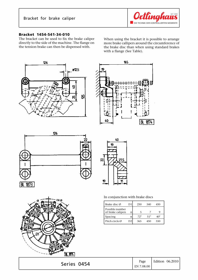
Bracket 1454-541-34-010
The bracket can be used to fix the brake caliperdirectly to the side of the machine. The flange onthe tension brake can then be dispensed with.
In conjunction with brake discs
Brake disc Ø D1 250 340 450
Possible numberof brake calipers n 5 7 9
Spacing α 72° 51° 40°
Pitch circle Ø D2 365 450 550
When using the bracket it is possible to arrangemore brake callipers around the circumference ofthe brake disc than when using standard brakeswith a flange (See Table).
EN 7.08.00
Edition 06.2010Page
Axial fanfor AC voltage
Series 0454
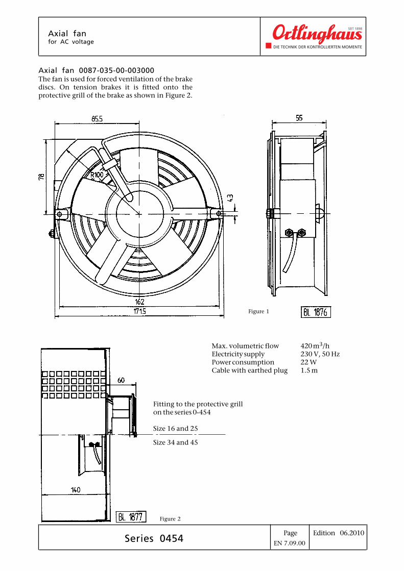
Axial fan 0087-035-00-003000The fan is used for forced ventilation of the brakediscs. On tension brakes it is fitted onto theprotective grill of the brake as shown in Figure 2.
Max. volumetric flow 420 m3/hElectricity supply 230 V, 50 HzPower consumption 22 WCable with earthed plug 1.5 m
Fitting to the protective grillon the series 0-454
Size 16 and 25
Size 34 and 45
Figure 1
Figure 2
EN 7.09.00

Edition 06.2010Page
Pneumatically actuatedwet-running high power brake
High power brake
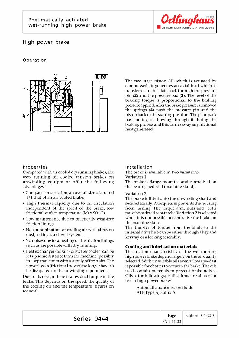
Operation
PropertiesCompared with air cooled dry running brakes, thewet- running oil cooled tension brakes onunwinding equipment offer the followingadvantages:
• Compact construction, an overall size of around1/4 that of an air cooled brake.
• High thermal capacity due to oil circulationindependent of the speed of the brake, lowfrictional surface temperature (Max 900 C).
• Low maintenance due to practically wear-freefriction linings.
• No contamination of cooling air with abrasiondust, as this is a closed system.
• No noises due to squealing of the friction liningssuch as are possible with dry-running.
• Heat exchanger (oil/air - oil/water cooler) can beset up some distance from the machine (possiblyin a separate room with a supply of fresh air). Thepower losses (frictional power) no longer have tobe dissipated on the unwinding equipment.
Due to its design there is a residual torque in thebrake. This depends on the speed, the quality ofthe cooling oil and the temperature (figures onrequest).
The two stage piston (1) which is actuated bycompressed air generates an axial load which istransferred to the plate pack through the pressurepin (2) and the pressure pad (3). The level of thebraking torque is proportional to the brakingpressure applied. After the brake pressure is removedthe springs (4) push the pressure pin and thepiston back to the starting position. The plate packhas cooling oil flowing through it during thebraking process and this carries away any frictionalheat generated.
InstallationThe brake is available in two variations:Variation 1:The brake is flange mounted and centralised onthe bearing pedestal (machine stand).
Variation 2:The brake is fitted onto the unwinding shaft andsecured axially. A torque arm prevents the housingfrom turning. The torque arm, nuts and boltsmust be ordered separately. Variation 2 is selectedwhen it is not possible to centralise the brake onthe machine stand.The transfer of torque from the shaft to theinternal drive hub can be either through a key andkeyway or a locking assembly.
Cooling and lubrication materialsThe friction characteristics of the wet-runninghigh power brake depend largely on the oil qualityselected. With unsuitable oils even at low speeds itis possible for chatter to occur in the brake. The oilsused contain materials to prevent brake noises.Oils to the following specifications are suitable foruse in high power brakes
Automatic transmission fluidsATF Type A, Suffix A
Series 0444EN 7.11.00

Edition 06.2010Page
Pneumatically actuatedwet-running high power brakeflanged version
Series 0444
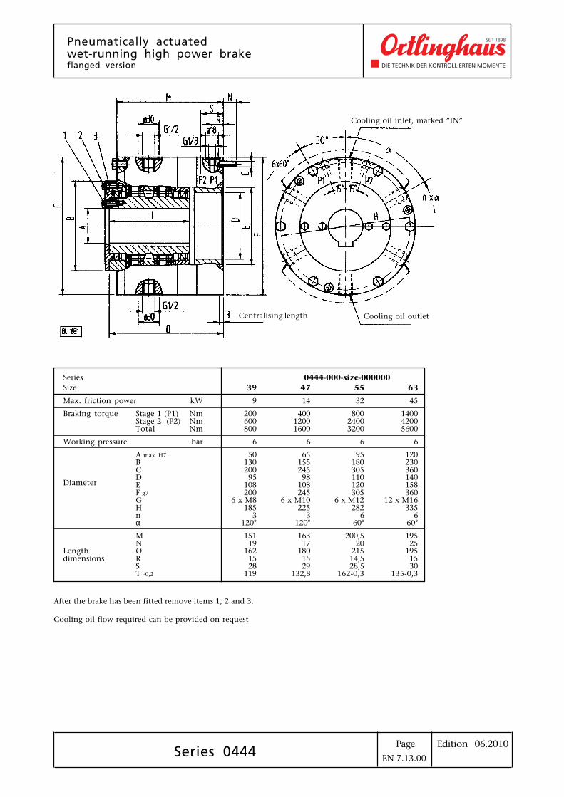
Series 0444-000-size-000000
Size 39 47 55 63
Max. friction power kW 9 14 32 45
Braking torque Stage 1 (P1) Nm 200 400 800 1400Stage 2 (P2) Nm 600 1200 2400 4200Total Nm 800 1600 3200 5600
Working pressure bar 6 6 6 6
A max H7 50 65 95 120B 130 155 180 230C 200 245 305 360
DiameterD 95 98 110 140E 108 108 120 158F g7 200 245 305 360G 6 x M8 6 x M10 6 x M12 12 x M16H 185 225 282 335n 3 3 6 6α 120° 120° 60° 60°
M 151 163 200,5 195N 19 17 20 25
Length O 162 180 215 195dimensions R 15 15 14,5 15
S 28 29 28,5 30T -0,2 119 132,8 162-0,3 135-0,3
After the brake has been fitted remove items 1, 2 and 3.
Cooling oil flow required can be provided on request
Cooling oil inlet, marked ”IN”
Centralising length Cooling oil outlet
EN 7.13.00
Edition 06.2010Page
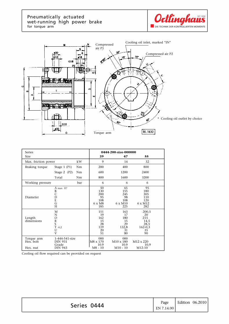
Pneumatically actuatedwet-running high power brakefor torque arm
Series 0444
Series 0444-200-size-000000
Size 39 47 55
Max. friction power kW 9 14 32
Braking torque Stage 1 (P1) Nm 200 400 800
Stage 2 (P2) Nm 600 1200 2400
Total Nm 800 1600 3200
Working pressure bar 6 6 6
A max H7 50 65 95B 130 155 180C 200 245 305
Diameter D 95 98 110E 108 108 120G 6 x M8 6 x M10 6 x M12H 185 225 282
M 151 163 200,5N 19 17 20
Length O 162 180 215dimensions R 15 15 14,5
S 28 29 28,5T -0,2 119 132,8 162-0,3U 20 31 35V 51 80 90
Torque arm 1-444-541-size 000 000Hex. bolt DIN 931 M8 x 170 M10 x 180 M12 x 220
Grade 10.9 10.9 10,9Hex. nut DIN 943 M8 - 10 M10 - 10 M12-10
* Cooling oil outlet by choice
Cooling oil flow required can be provided on request
Compressedair P1
Compressed air P2
Cooling oil inlet, marked ”IN”
Torque arm
EN 7.14.00
Edition 06.2010PageSeries 0444
Hydraulic power pack with cooler
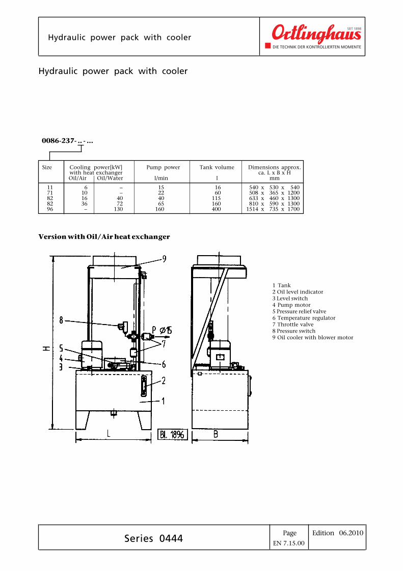
Hydraulic power pack with cooler
0086-237- .. - ...
Size Cooling power[kW] Pump power Tank volume Dimensions approx.with heat exchanger ca. L x B x HOil/Air Oil/Water l/min l mm
11 6 – 15 16 540 x 530 x 54071 10 – 22 60 508 x 365 x 120082 16 40 40 115 633 x 460 x 130082 36 72 65 160 810 x 590 x 130096 – 130 160 400 1514 x 735 x 1700
Version with Oil/Air heat exchanger
1 Tank2 Oil level indicator3 Level switch4 Pump motor5 Pressure relief valve6 Temperature regulator7 Throttle valve8 Pressure switch9 Oil cooler with blower motor
EN 7.15.00
Edition 06.2010PageSeries 0444
Pneumatically actuatedwet-running high power brake
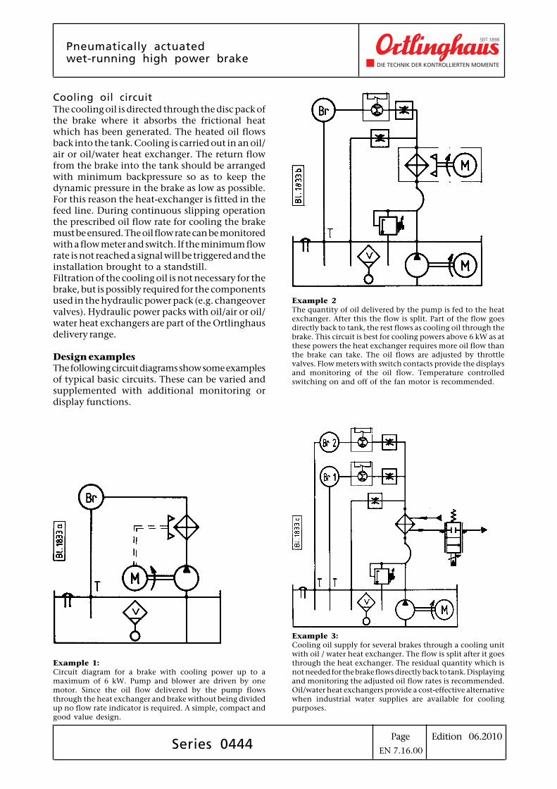
Cooling oil circuitThe cooling oil is directed through the disc pack ofthe brake where it absorbs the frictional heatwhich has been generated. The heated oil flowsback into the tank. Cooling is carried out in an oil/air or oil/water heat exchanger. The return flowfrom the brake into the tank should be arrangedwith minimum backpressure so as to keep thedynamic pressure in the brake as low as possible.For this reason the heat-exchanger is fitted in thefeed line. During continuous slipping operationthe prescribed oil flow rate for cooling the brakemust be ensured. The oil flow rate can be monitoredwith a flow meter and switch. If the minimum flowrate is not reached a signal will be triggered and theinstallation brought to a standstill.Filtration of the cooling oil is not necessary for thebrake, but is possibly required for the componentsused in the hydraulic power pack (e.g. changeovervalves). Hydraulic power packs with oil/air or oil/water heat exchangers are part of the Ortlinghausdelivery range.
Design examplesThe following circuit diagrams show some examplesof typical basic circuits. These can be varied andsupplemented with additional monitoring ordisplay functions.
Example 1:Circuit diagram for a brake with cooling power up to amaximum of 6 kW. Pump and blower are driven by onemotor. Since the oil flow delivered by the pump flowsthrough the heat exchanger and brake without being dividedup no flow rate indicator is required. A simple, compact andgood value design.
Example 2The quantity of oil delivered by the pump is fed to the heatexchanger. After this the flow is split. Part of the flow goesdirectly back to tank, the rest flows as cooling oil through thebrake. This circuit is best for cooling powers above 6 kW as atthese powers the heat exchanger requires more oil flow thanthe brake can take. The oil flows are adjusted by throttlevalves. Flow meters with switch contacts provide the displaysand monitoring of the oil flow. Temperature controlledswitching on and off of the fan motor is recommended.
Example 3:Cooling oil supply for several brakes through a cooling unitwith oil / water heat exchanger. The flow is split after it goesthrough the heat exchanger. The residual quantity which isnot needed for the brake flows directly back to tank. Displayingand monitoring the adjusted oil flow rates is recommended.Oil/water heat exchangers provide a cost-effective alternativewhen industrial water supplies are available for coolingpurposes.
EN 7.16.00
Edition 06.2010PageSeries 0444
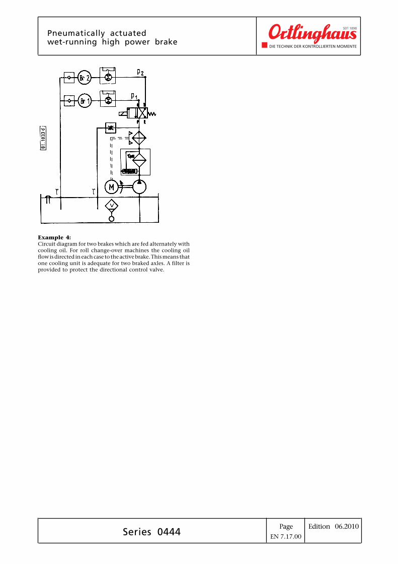
Example 4:Circuit diagram for two brakes which are fed alternately withcooling oil. For roll change-over machines the cooling oilflow is directed in each case to the active brake. This means thatone cooling unit is adequate for two braked axles. A filter isprovided to protect the directional control valve.
Pneumatically actuatedwet-running high power brake
EN 7.17.00

Edition 06.2010PageSeries 0087-454-21-015
TENSIONOR IElectronic web tension open-loop control with ultrasonic sensor
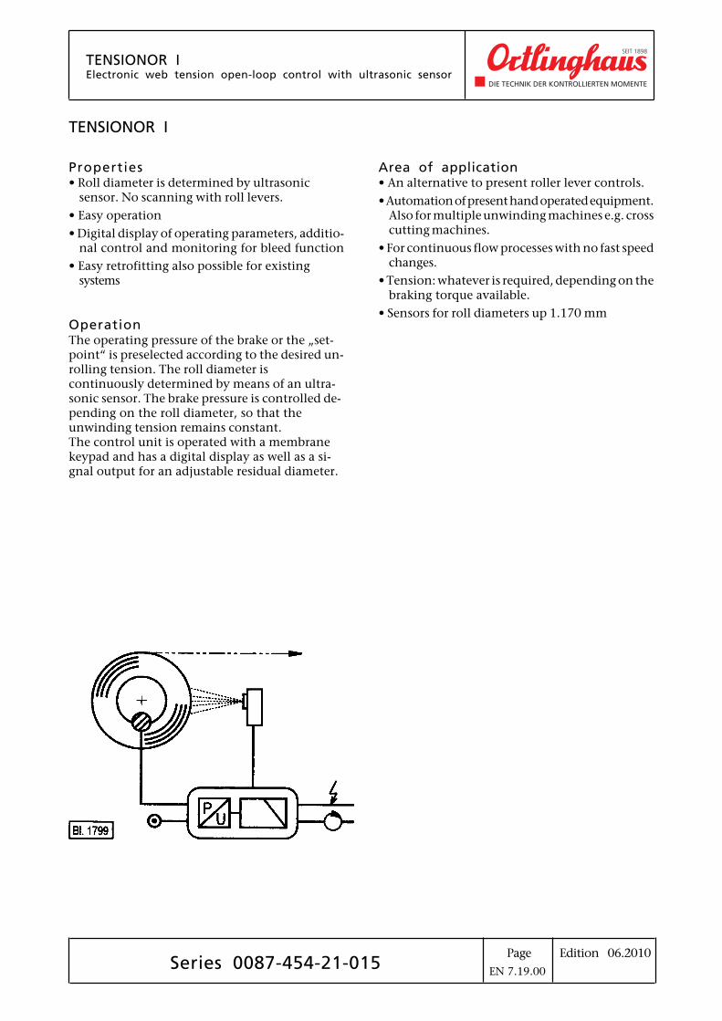
TENSIONOR I
Properties• Roll diameter is determined by ultrasonic
sensor. No scanning with roll levers.
• Easy operation
• Digital display of operating parameters, additio-nal control and monitoring for bleed function
• Easy retrofitting also possible for existingsystems
OperationThe operating pressure of the brake or the „set-point“ is preselected according to the desired un-rolling tension. The roll diameter iscontinuously determined by means of an ultra-sonic sensor. The brake pressure is controlled de-pending on the roll diameter, so that theunwinding tension remains constant.The control unit is operated with a membranekeypad and has a digital display as well as a si-gnal output for an adjustable residual diameter.
Area of application• An alternative to present roller lever controls.
• Automation of present hand operated equipment.Also for multiple unwinding machines e.g. crosscutting machines.
• For continuous flow processes with no fast speedchanges.
• Tension: whatever is required, depending on thebraking torque available.
• Sensors for roll diameters up 1.170 mm
EN 7.19.00
Edition 06.2010Page
TENSIONOR IElectronic web tension open-loop control with ultrasonic sensor
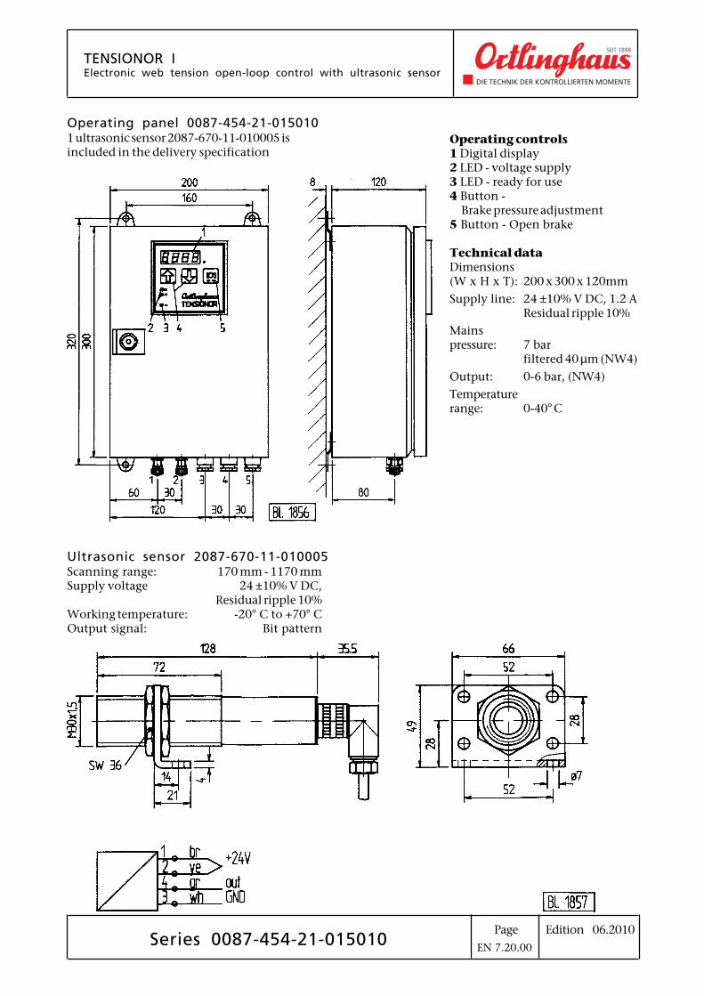
Series 0087-454-21-015010
Operating controls1 Digital display2 LED - voltage supply3 LED - ready for use4 Button -
Brake pressure adjustment5 Button - Open brake
Technical dataDimensions(W x H x T): 200 x 300 x 120mm
Supply line: 24 ±10% V DC, 1.2 AResidual ripple 10%
Mainspressure: 7 bar
filtered 40 µm (NW4)
Output: 0-6 bar, (NW4)
Temperaturerange: 0-40° C
Ultrasonic sensor 2087-670-11-010005Scanning range: 170 mm - 1170 mmSupply voltage 24 ±10% V DC,
Residual ripple 10%Working temperature: -20° C to +70° COutput signal: Bit pattern
Operating panel 0087-454-21-0150101 ultrasonic sensor 2087-670-11-010005 isincluded in the delivery specification
EN 7.20.00