Embed Size (px)
Citation preview

WIRE HARNESS INSTALLATION INSTRUCTIONS
For Installing:
#10205 Classic Plus Customizable GM Pickup Chassis Harness – 1973-87 – 27 Circuit
Manual #90507

Painless Performance Products, LLC 2501 Ludelle Street
Fort Worth, TX 76105-1036 800-423-9696 phone – 817-244-4024 fax
Web Site: www.painlessperformance.com E-Mail: [email protected]
If you have any questions concerning the installation of this product, feel free to call Painless Performance Products' tech line at 1-800-423-9696. Calls are answered from 8am to 5pm central time, Monday thru Thursday, 8am-4:30pm Friday, except holidays. Here we have provided you with accurate instructions for the installation of this product. However, if you have comments/suggestions concerning these instructions, please call or email us (our contact information can be found at the top of this page or online at www.painlessperformance.com).We sincerely appreciate your business.
Painless Performance Products, LLC shall in no event be liable in contract or tort (including negligence) for special, indirect, incidental, or consequential damages, such as but not limited to, loss of property, or any other damages, costs or expenses which might be claimed as the result of the use or failure of the goods sold hereby, except only the cost of repair or replacement.
Should you damage or lose part of your manual, a full color copy of these instructions can be found online at www.painlessperformance.com
Installation Manual: 90507
10th Edition: January 14, 2014
Copyright 1997 by Painless Performance Products, LLC
NOTE :
If your vehicle has an existing harness, you will want to retain it for the possible re-use of various Pigtails & Connector housings, particular to your application. Included in this kit is a sheet of pre-printed labels, to assist in identifying of connections as the existing harness is removed from the vehicle. If you do not have an existing harness, there is a package of terminals included with the harness that will enable you to make most of the connections needed. Replacement lighting pigtails & sockets can be readily obtained from your local parts distributor
Painless Performance has included 20 extra male and female bulkhead terminals in this harness kit. Use these extra terminals to run wires through the firewall using the male and female bulkhead connectors on the harness. See below for instructions on how to use these terminals. The terminals we have provided you are designed for wire gauges 18-14. Strip ¼” of the insulation from the wire and then crimp it to the terminal using the correct terminal crimping tool. These terminals are roll crimp style. You can purchase this type of terminal crimper from Painless, part # 70900. See below for a picture of the correct terminal crimping tool and how to use them. Take a look at how the terminals we inserted into the bulkhead connector here at the factory. Notice they are orientated a certain direction. Insert the blade (male) terminal into the engine compartment side bulkhead connector. Insert the female terminal into the passenger compartment side of the bulkhead connector.
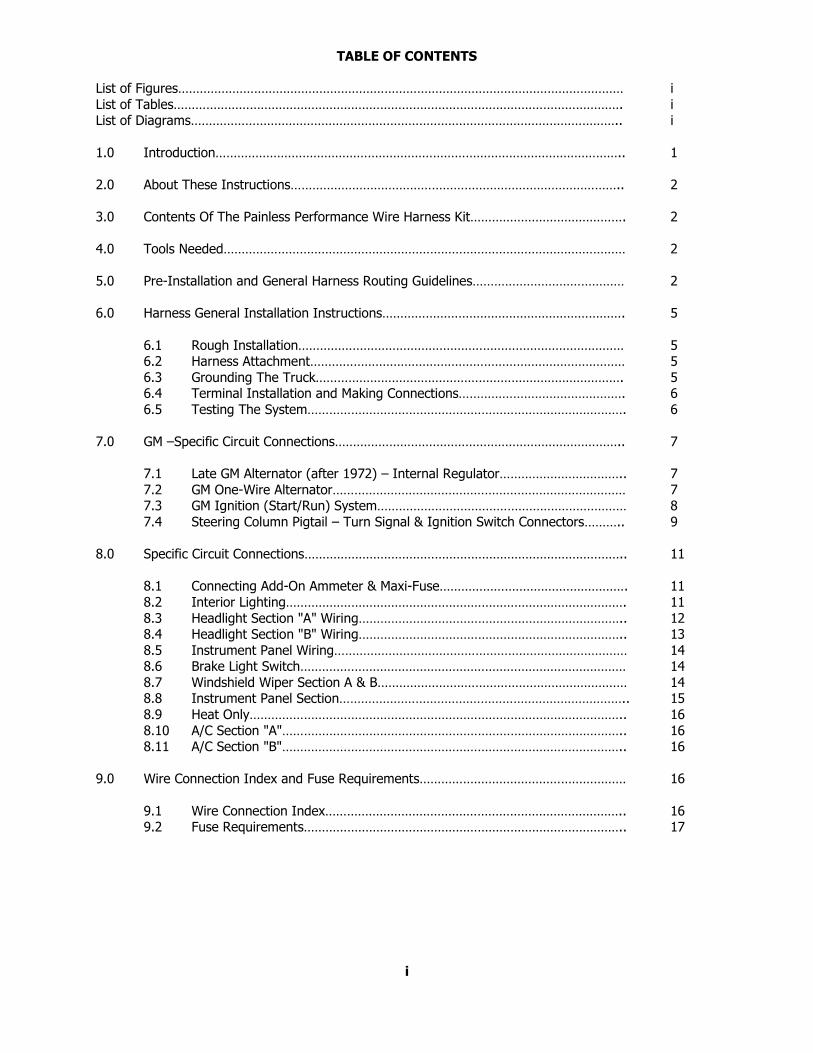
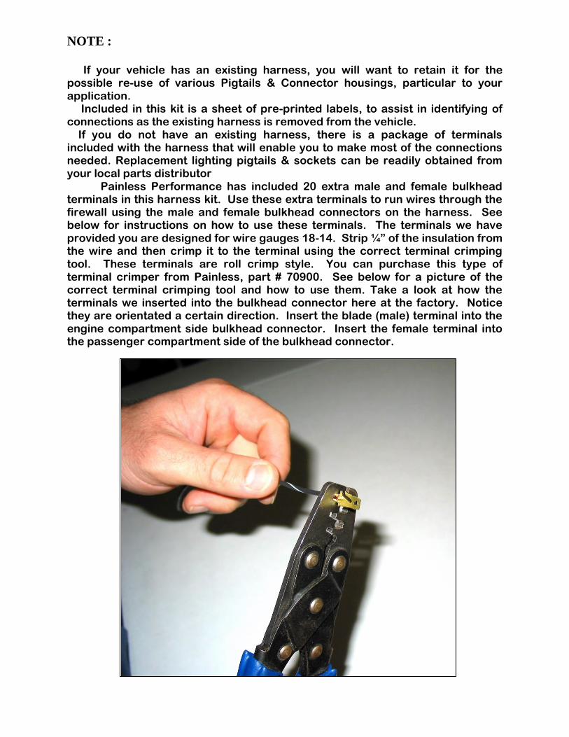
TABLE OF CONTENTS
List of Figures…………………………………………………………………………………………………………… i
List of Tables……………………………………………………………………………………………………………. i List of Diagrams……………………………………………………………………………………………………….. i
1.0 Introduction………………………………………………………………………………………………….. 1
2.0 About These Instructions……………………………………………………………………………….. 2
3.0 Contents Of The Painless Performance Wire Harness Kit……………………………………. 2
4.0 Tools Needed………………………………………………………………………………………………… 2
5.0 Pre-Installation and General Harness Routing Guidelines…………………………………… 2
6.0 Harness General Installation Instructions…………………………………………………………. 5
6.1 Rough Installation……………………………………………………………………………… 5 6.2 Harness Attachment…………………………………………………………………………… 5
6.3 Grounding The Truck…………………………………………………………………………. 5 6.4 Terminal Installation and Making Connections………………………………………. 6
6.5 Testing The System……………………………………………………………………………. 6
7.0 GM –Specific Circuit Connections…………………………………………………………………….. 7
7.1 Late GM Alternator (after 1972) – Internal Regulator…………………………….. 7
7.2 GM One-Wire Alternator……………………………………………………………………… 7 7.3 GM Ignition (Start/Run) System…………………………………………………………… 8
7.4 Steering Column Pigtail – Turn Signal & Ignition Switch Connectors……….. 9
8.0 Specific Circuit Connections…………………………………………………………………………….. 11
8.1 Connecting Add-On Ammeter & Maxi-Fuse……………………………………………. 11
8.2 Interior Lighting…………………………………………………………………………………. 11
8.3 Headlight Section "A" Wiring……………………………………………………………….. 12 8.4 Headlight Section "B" Wiring……………………………………………………………….. 13
8.5 Instrument Panel Wiring……………………………………………………………………… 14 8.6 Brake Light Switch……………………………………………………………………………… 14
8.7 Windshield Wiper Section A & B…………………………………………………………… 14 8.8 Instrument Panel Section…………………………………………………………………….. 15
8.9 Heat Only………………………………………………………………………………………….. 16
8.10 A/C Section "A"………………………………………………………………………………….. 16 8.11 A/C Section "B"………………………………………………………………………………….. 16
9.0 Wire Connection Index and Fuse Requirements………………………………………………… 16
9.1 Wire Connection Index……………………………………………………………………….. 16 9.2 Fuse Requirements…………………………………………………………………………….. 17
i
LIST OF FIGURES
Figure 7.1 Late GM Alternator – Internal Regulator……………………………………………….. 7
Figure 7.2 Maxi-Fuse………………………………………………………………………………………….. 8 Figure 7.3 GM Ignition (Start/Run) System…………………………………………………………… 9
Figure 7.4 GM Turn Signal Connectors…………………………………………………………………. 10
Figure 8.1 Ammeter & Maxi-Fuse………………………………………………………………………… 11 Figure 8.2 Interior Lighting…………………………………………………………………………………. 12
Figure 8.3 Headlight Section "A" Wiring……………………………………………………………….. 13 Figure 8.4 Dimmer Switches……………………………………………………………………………….. 13
Figure 8.5 Headlight Section "B" Wiring……………………………………………………………….. 14
LIST OF TABLES
Table 7-1 GM Ignition & Turn Signal Wiring…………………………………………………………. 10 Table 9-1 Fuse Requirements…………………………………………………………………………….. 17
Table 9-2 Wire Connection Index, 1 of 4…………………………………………………………….. 18
Table 9-2 Wire Connection Index, 2 of 4……………………………………………………………… 19 Table 9-2 Wire Connection Index, 3 of 4…………………………………………………………….. 20
Table 9-2 Wire Connection Index, 4 of 4…………………………………………………………….. 21
LIST OF DIAGRAMS
Diagram 1 Wiper Washer System (1973-1978)……………………………………………………… 22 Diagram 2 Wiper Washer Motor & Pump (1973-1978)…………………………………………… 23
Diagram 3 1973 Typical A/C-Heater (C-K Models)…………………………………………………. 24 Diagram 4 Wiper Washer System (1978-1986)…………………………………………………….. 25
Diagram 5 1973-1978 with Gauges (mechanical oil gauge)……………………………………. 26
Diagram 6 1973-1985 with Gauges (mechanical oil gauge)……………………………………. 26 Diagram 7 1986 with Gauges……………………………………………………………………………… 27
Diagram 8 1973-1986 with Warning Lights (no gauges)………………………………………… 27 Diagram 9 Blower Switch and 3-Pin Resistor………………………………………………………… 28
Diagram 10 Blower Speed Switch…………………………………………………………………………. 29
ii
1.0 INTRODUCTION
You have purchased what we at Painless Performance believe to be the most up-to-date and
easiest to install truck wire harness on the market. It is designed for easy installation, even if you have no electrical experience.
The fuse block, can be easily mounted in the factory location. The fuse block, voltmeter, fuel gauge, oil pressure gauge, temperature gauge, turn signal lights, high beam switch and dash
lights are all pre-wired, allowing for easy hookup.
The proper fuses and flashers have been pre-installed in the fuse block. In addition, all wires are
color-coded. This will help you to identify the different circuits during installation and later on if additions to the overall system are necessary. For fuse specifications and wire color designations
see Section 9.0.
This complete truck wiring system has been designed with three major groups incorporated into it:
Engine/Headlight Group Includes high beam, low beam, park, right turn, left turn, electric fan, horn, starter solenoid and
battery feed, alternator and alternator exciter wire, distributor, water temperature, oil pressure and air conditioning.
Dash Group Includes wires to connect gauges, indicator lights and switches to their proper sources, also
includes door locks, power windows and electric fuel pump.
Rear Light Group
Includes taillights, left and right turn signals, brake light and fuel sender.
NOTE: The wire numbers referred to in these instructions are for reference to the diagrams in the back of this book only.
2.0 ABOUT THESE INSTRUCTIONS
The contents of these instructions are divided into major Sections, as follows:
1.0 Introduction 2.0 About these instructions
3.0 Contents of PPPI Wire Harness Kit
4.0 Tools needed 5.0 Pre-Installation and General Harness Routing Guidelines
6.0 General Harness Installation Instructions 7.0 GM-Specific Circuit Connection Details
8.0 Specific Circuit Connection Details 9.0 Wire Connection Index and Fuse Requirements
Sections are divided into subsections and Paragraphs. Throughout these instructions, the Figure numbers refer to illustrations and the Table numbers refer to information in table form.
These are located in Sections and Paragraphs corresponding to the number. Always pay special and careful attention to any Notes, especially those in the Tables, and any text marked
CAUTION.
1
3.0 CONTENTS OF THE PAINLESS PERFORMANCE WIRE HARNESS KIT
Refer to the following list to take inventory. See that you have everything you're supposed to
have in this kit. If anything is missing, contact the dealer where you obtained the kit or Painless Performance at (800) 423-9696. The Painless Performance Wire Harness Kit should contain the
following items:
The main wire harness, with the fuse block wired and fuses installed.
The engine harness
4 headlamp connector cables
2 fender well grommets (for headlamps)
2 packages of nylon tie wraps
Parts Box, containing the maxi-fuse, GM alternator connectors, terminals, splices, etc.
Part #90507 Painless Performance Manual (this booklet)
4.0 TOOLS NEEDED
In addition to your regular tools, you will need, at least, the following tools:
Crimping tool NOTE: Use a quality tool to avoid over-crimping Wire Stripper
Continuity Tester (test light or ohm meter)
Small (10 amp or less) Battery Charger
5.0 PRE-INSTALLATION AND GENERAL HARNESS ROUTING GUIDELINES
CAUTION: IF YOUR 1973-78 VEHICLE IS EQUIPPED WITH FACTORY AIR
CONDITIONING, DO NOT REMOVE THE FACTORY WIRING, AS IT MUST BE USED WITH THIS KIT. THE WIRING IN THIS KIT IS FOR A HEATER SYSTEM ONLY. SEE ATTACHED DIAGRAM FOR SUGGESTED CONNECTION OF PAINLESS WIRING TO YOUR SYSTEM. (NOTE: FACTORY AIR CONDITIONING SYSTEMS MAY VARY FROM THIS DIAGRAM. CONSULT FACTORY DIAGRAMS FOR YOUR VEHICLE TO ENSURE PROPER CONNECTIONS.
The installation of your wire harness mainly consists in two parts:
The physical routing and securing of the wire harness, wires and groups.
The proper connection of the individual circuits.
These two major tasks are not separate steps, but are integrated together. That is, you will route
some wires and make some connections, route some more wire and make some more connections.
2 We cannot tell you how to physically route the harness in your truck. That depends a great deal
upon the particular year of your truck and to what extent you want to secure and conceal the
harness. We do offer some general guidelines and routing practices starting in Section 5.2,
general installation instructions in Section 6.0, and precise instructions concerning the electrical connections you will have to make in beginning in Section 7.0. To help you begin thinking
through the installation of your wire harness, read the following sections:
5.1 Familiarize yourself with the harness by locating each of the harness sections in the
following list. (Whenever a particular harness section is referred to in these instructions it is shown in "all caps"; ENGINE SECTION A):
ACCESSORY SECTION SWITCHES ENGINE SECTION A
ACCESSORY SECTION B+ ENGINE SECTION B A/C SECTION A HEADLIGHT SECTION A
A/C SECTION B HEADLIGHT SECTION B
BRAKE SWITCH SECTION IGNITION SWITCH SECTION COURTESY LIGHT SECTION INSTRUMENT PANEL SECTION
CRUISE CONTROL SECTION RADIO SECTION DIMMER SWITCH SECTION TAIL SECTION
DOME SECTION TURN SIGNAL SECTION
DOOR SECTION A WINDSHIELD WASHER SECTION DOOR SECTION B WIPER SECTION A
EMERGENCY BRAKE SECTION WIPER SECTION B
Note: For complete information concerning the individual circuits and wires that make up harness SECTIONS, see Section 9.0.
5.2 The Painless Wire Harness is designed for the fuse block to be mounted on the driver's side, under the dash, in the factory location.
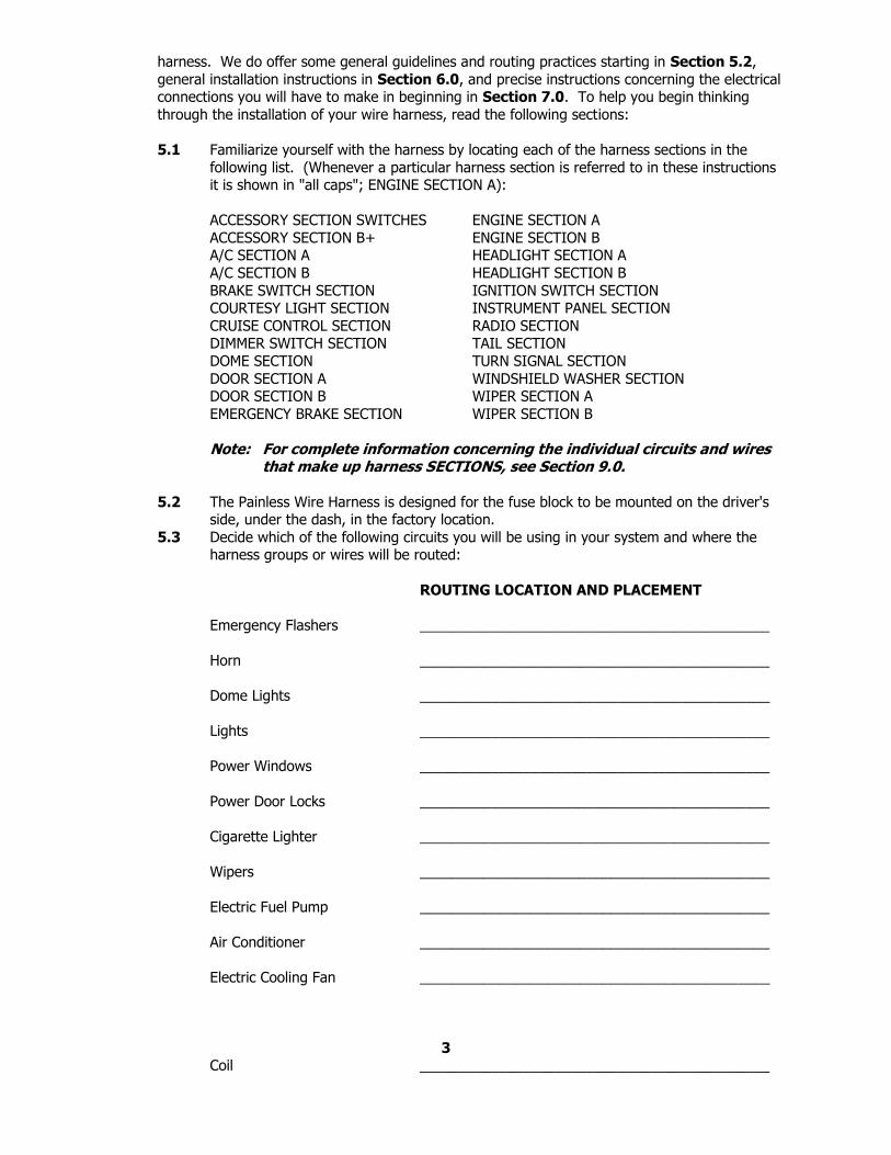
5.3 Decide which of the following circuits you will be using in your system and where the harness groups or wires will be routed:
ROUTING LOCATION AND PLACEMENT
Emergency Flashers ____________________________________________
Horn ____________________________________________
Dome Lights ____________________________________________
Lights ____________________________________________
Power Windows ____________________________________________
Power Door Locks ____________________________________________
Cigarette Lighter ____________________________________________
Wipers ____________________________________________
Electric Fuel Pump ____________________________________________
Air Conditioner ____________________________________________
Electric Cooling Fan ____________________________________________
3 Coil ____________________________________________
Turn Signals ____________________________________________
Radio Ign. Switched B+ ____________________________________________
Radio Constant B+ ____________________________________________
Gauges ____________________________________________
Accessories ____________________________________________
Backup Lights ____________________________________________
Cruise Control ____________________________________________
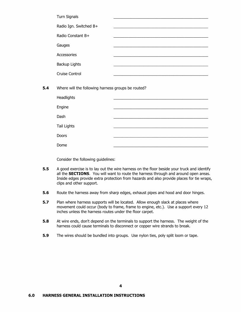
5.4 Where will the following harness groups be routed?
Headlights ____________________________________________
Engine ____________________________________________
Dash ____________________________________________
Tail Lights ____________________________________________
Doors ____________________________________________
Dome ____________________________________________
Consider the following guidelines:
5.5 A good exercise is to lay out the wire harness on the floor beside your truck and identify all the SECTIONS. You will want to route the harness through and around open areas.
Inside edges provide extra protection from hazards and also provide places for tie wraps,
clips and other support.
5.6 Route the harness away from sharp edges, exhaust pipes and hood and door hinges.
5.7 Plan where harness supports will be located. Allow enough slack at places where movement could occur (body to frame, frame to engine, etc.). Use a support every 12
inches unless the harness routes under the floor carpet.
5.8 At wire ends, don't depend on the terminals to support the harness. The weight of the
harness could cause terminals to disconnect or copper wire strands to break.
5.9 The wires should be bundled into groups. Use nylon ties, poly split loom or tape.
4
6.0 HARNESS GENERAL INSTALLATION INSTRUCTIONS
6.1 Rough Installation
CAUTION: DISCONNECT THE POWER FROM YOUR TRUCK BY REMOVING BOTH BATTERY CABLES FROM THE BATTERY, AND RECONNECT THEM AFTER INSTALLATION IS COMPLETE.
Note: Make no wire connections or permanent mounting of any kind
at this time!
6.1.1 Position the fuse block in its mounting area. 6.1.2 Route dash group (ACCESSORY SECTION B+, ACCESSORY SECTION SWITCHES,
INSTRUMENT PANEL SECTION, RADIO SECTION, etc.) upward to rear of dash
and temporarily tie in place. 6.1.3 Position rear groups, consisting of DOOR SECTIONS A & B and SPEAKER
SECTION, etc. 6.1.4 Plug in the ENGINE HARNESS and route the HEADLIGHT and ENGINE SECTION
forward, and the TAIL SECTION towards the rear.
6.2 Harness Attachment
Note: Harness routing and shaping is, and should be, a time-consuming task.
Taking your time will enhance the beauty of your installation. Please be patient and TAKE YOUR TIME.
6.2.1 Permanently mount the fuse block. Do not over tighten mounting bolts! 6.2.2 Mold harness groups to the contour of floor pan, firewall, fender panels and any
other area where wires or harness groups are routed. Remember to route the harness away from sharp edges, exhaust pipes, hood and door hinges, etc.
6.2.3 Attach harness groups to your truck with clips or ties starting at the fuse block
and working toward the front and along the floor pan or frame for the rear group. The dash wires should be routed out of the way of any under-dash
obstacles, such as the cowl vent, air conditioning, radio, etc.
Note: Do not tighten tie wraps and mounting devices at this time. Make all harness attachments loosely.
6.2.4 When used every 1-1/2" or so on the visible areas of the harness, the plastic wire ties make a very attractive assembly. A tie installed in other areas every 6"
or so will hold the wires in place nicely. Remember to take your time!
6.3 Grounding the Truck
A perfectly and beautifully wired truck will nevertheless have bugs and problems if
everything is not properly grounded. Do not go to the careful effort of installing a quality wire harness only to neglect proper grounding.
Note: The Painless Performance Wire Harness Kit includes no ground wire except the black wire from the dash and headlamp connectors. You must supply ground wire (14-16 gauge) for all circuits where required.
5 6.3.1 Connect a ground strap or cable (even a 10 gauge wire is too small) from the
negative battery terminal to the engine.
6.3.2 Connect a ground strap from the engine to the chassis. DO NOT RELY UPON
THE MOTOR MOUNTS TO MAKE THIS CONNECTION. 6.3.3 Connect a ground strap from the engine to the body.
6.4 Terminal Installation and Making Connections
Note: In the following steps you will be making the circuit connections. Before you start, you should carefully read Sections 7.0 and 8.0, as appropriate, and continually refer to Section 9.0, DOUBLE-CHECKING your routing and length calculations before cutting any wires and making connections. Give special attention to turn signal and ignition switch connections. These can be somewhat confusing.
6.4.1 Have all needed tools and connectors handy. 6.4.2 Select the correct size terminal for the wire and stud application.
6.4.3 Determine the correct wire length and cut the wire. Remember to allow enough slack in the harness and wires at places where movement could possibly occur,
such as truck body to frame, frame to engine, etc. Double-check your
calculations. 6.4.4 Strip insulation away from wire. Strip only enough necessary for the type of
terminal lug you are using.
Note: In the following step, make sure that the terminal is crimped with the proper die in the crimping tool. An improper crimp will NOT make a good connection.
6.4.5 Crimp the terminal onto the wire.
CAUTION: DO NOT OVER-CRIMP!
6.4.6 Connecting the harness throughout the groups is a redundant process. Make sure that each wire is FIRST properly routed and THEN attach. DO NOT ATTACH
FIRST THEN ROUTE AFTERWARD. 6.4.7 When all wires are attached, tighten the mounts and ties to secure harness
permanently.
6.5 Testing the System
6.5.1 Use a small (10 amp or less) battery charger to power up the truck for circuit
testing. If there is a problem anywhere, the battery charger's low amperage and internal circuit breaker will provide circuit protection.
CAUTION: IF YOU HAVE NOT YET DISCONNECTED THE BATTERY, DO SO NOW! DO NOT CONNECT THE BATTERY CHARGER WITH THE BATTERY CONNECTED.
Connect the battery charger's NEGATIVE output to the chassis or engine block
and its POSITIVE output to the positive battery terminal on the starter.
6.5.2 INDIVIDUALLY turn on each light, ignition, wiper circuit, etc, and check for proper operation.
6.5.3 When all circuits check out THEN attach the battery cable to the battery for vehicle operation.
6
7.0 GM - SPECIFIC CIRCUIT CONNECTIONS
Note: Your alternator may not appear exactly as represented in the Figures.
The circuits are wired the same way though. Wire numbers referred to are only for diagram reference only. The wires are marked and color-coded.
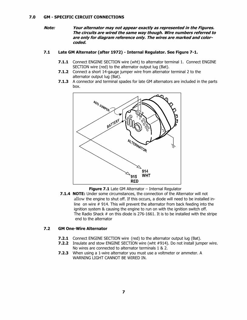
7.1 Late GM Alternator (after 1972) - Internal Regulator. See Figure 7-1.
7.1.1 Connect ENGINE SECTION wire (wht) to alternator terminal 1. Connect ENGINE
SECTION wire (red) to the alternator output lug (Bat).
7.1.2 Connect a short 14-gauge jumper wire from alternator terminal 2 to the alternator output lug (Bat).
7.1.3 A connector and terminal spades for late GM alternators are included in the parts box.
Figure 7.1 Late GM Alternator – Internal Regulator 7.1.4 NOTE: Under some circumstances, the connection of the Alternator will not
allow the engine to shut off. If this occurs, a diode will need to be installed in-
line on wire # 914. This will prevent the alternator from back feeding into the ignition system & causing the engine to run on with the ignition switch off.
The Radio Shack # on this diode is 276-1661. It is to be installed with the stripe
end to the alternator
7.2 GM One-Wire Alternator
7.2.1 Connect ENGINE SECTION wire (red) to the alternator output lug (Bat). 7.2.2 Insulate and stow ENGINE SECTION wire (wht #914). Do not install jumper wire.
No wires are connected to alternator terminals 1 & 2.
7.2.3 When using a 1-wire alternator you must use a voltmeter or ammeter. A WARNING LIGHT CANNOT BE WIRED IN.
7
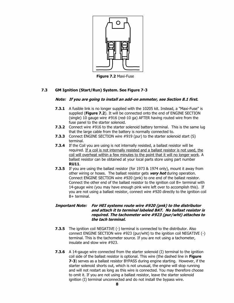
Figure 7.2 Maxi-Fuse
7.3 GM Ignition (Start/Run) System. See Figure 7-3
Note: If you are going to install an add-on ammeter, see Section 8.1 first.
7.3.1 A fusible link is no longer supplied with the 10205 kit. Instead, a "Maxi-Fuse" is supplied (Figure 7.2). It will be connected onto the end of ENGINE SECTION
(single) 10 gauge wire #916 (red-10 ga) AFTER having routed wire from the fuse panel to the starter solenoid.
7.3.2 Connect wire #916 to the starter solenoid battery terminal. This is the same lug
that the large cable from the battery is normally connected to. 7.3.3 Connect ENGINE SECTION wire #919 (pur) to the starter solenoid start (S)
terminal. 7.3.4 If the Coil you are using is not internally resisted, a ballast resistor will be
required. If a coil is not internally resisted and a ballast resistor is not used, the
coil will overheat within a few minutes to the point that it will no longer work. A ballast resistor can be obtained at your local parts store using part number
RU11. 7.3.5 If you are using the ballast resistor (for 1973 & 1974 only), mount it away from
other wiring or hoses. The ballast resistor gets very hot during operation.
Connect ENGINE SECTION wire #920 (pnk) to one end of the ballast resistor. Connect the other end of the ballast resistor to the ignition coil B+ terminal with
14-gauge wire (you may have enough pink wire left over to accomplish this). If you are not using a ballast resistor, connect wire #920 directly to the ignition coil
B+ terminal.
Important Note: For HEI systems route wire #920 (pnk) to the distributor and attach it to terminal labeled BAT. No ballast resistor is required. The tachometer wire #923 (pur/wht) attaches to the tach terminal.
7.3.5 The ignition coil NEGATIVE (-) terminal is connected to the distributor. Also
connect ENGINE SECTION wire #923 (pur/wht) to the ignition coil NEGATIVE (-) terminal. This is the tachometer source. If you are not using a tachometer,
insulate and stow wire #923.
7.3.6 A 14-gauge wire connected from the starter solenoid (I) terminal to the ignition coil side of the ballast resistor is optional. This wire (the dashed line in Figure
7-3) serves as a ballast resistor BYPASS during engine starting. However, if the
starter solenoid shorts out, which is not unusual, the engine will stop running and will not restart as long as this wire is connected. You may therefore choose
to omit it. If you are not using a ballast resistor, leave the starter solenoid ignition (I) terminal unconnected and do not install the bypass wire.
8
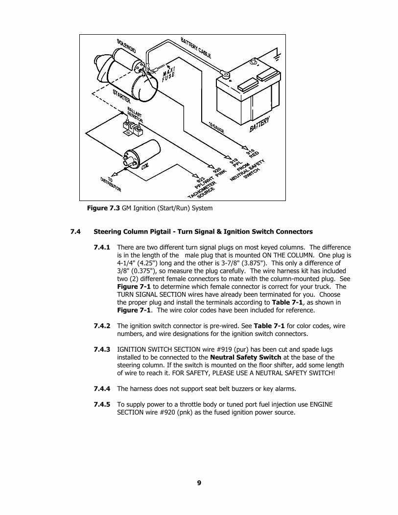
Figure 7.3 GM Ignition (Start/Run) System
7.4 Steering Column Pigtail - Turn Signal & Ignition Switch Connectors
7.4.1 There are two different turn signal plugs on most keyed columns. The difference
is in the length of the male plug that is mounted ON THE COLUMN. One plug is
4-1/4" (4.25") long and the other is 3-7/8" (3.875"). This only a difference of 3/8" (0.375"), so measure the plug carefully. The wire harness kit has included
two (2) different female connectors to mate with the column-mounted plug. See Figure 7-1 to determine which female connector is correct for your truck. The
TURN SIGNAL SECTION wires have already been terminated for you. Choose
the proper plug and install the terminals according to Table 7-1, as shown in Figure 7-1. The wire color codes have been included for reference.
7.4.2 The ignition switch connector is pre-wired. See Table 7-1 for color codes, wire
numbers, and wire designations for the ignition switch connectors.
7.4.3 IGNITION SWITCH SECTION wire #919 (pur) has been cut and spade lugs
installed to be connected to the Neutral Safety Switch at the base of the steering column. If the switch is mounted on the floor shifter, add some length
of wire to reach it. FOR SAFETY, PLEASE USE A NEUTRAL SAFETY SWITCH!
7.4.4 The harness does not support seat belt buzzers or key alarms.
7.4.5 To supply power to a throttle body or tuned port fuel injection use ENGINE
SECTION wire #920 (pnk) as the fused ignition power source.
9
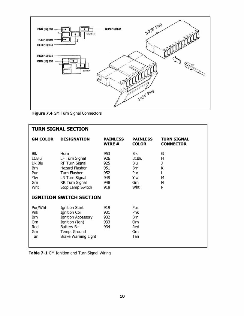
Figure 7.4 GM Turn Signal Connectors
Table 7-1 GM Ignition and Turn Signal Wiring
10
TURN SIGNAL SECTION
GM COLOR DESIGNATION PAINLESS PAINLESS TURN SIGNAL WIRE # COLOR CONNECTOR
Blk Horn 953 Blk G
Lt.Blu LF Turn Signal 926 Lt.Blu H Dk.Blu RF Turn Signal 925 Blu J
Brn Hazard Flasher 951 Brn K
Pur Turn Flasher 952 Pur L Ylw LR Turn Signal 949 Ylw M
Grn RR Turn Signal 948 Grn N Wht Stop Lamp Switch 918 Wht P
IGNITION SWITCH SECTION
Pur/Wht Ignition Start 919 Pur Pnk Ignition Coil 931 Pnk
Brn Ignition Accessory 932 Brn
Orn Ignition (Ign) 933 Orn Red Battery B+ 934 Red
Grn Temp. Ground Grn Tan Brake Warning Light Tan
8.0 SPECIFIC CIRCUIT CONNECTIONS
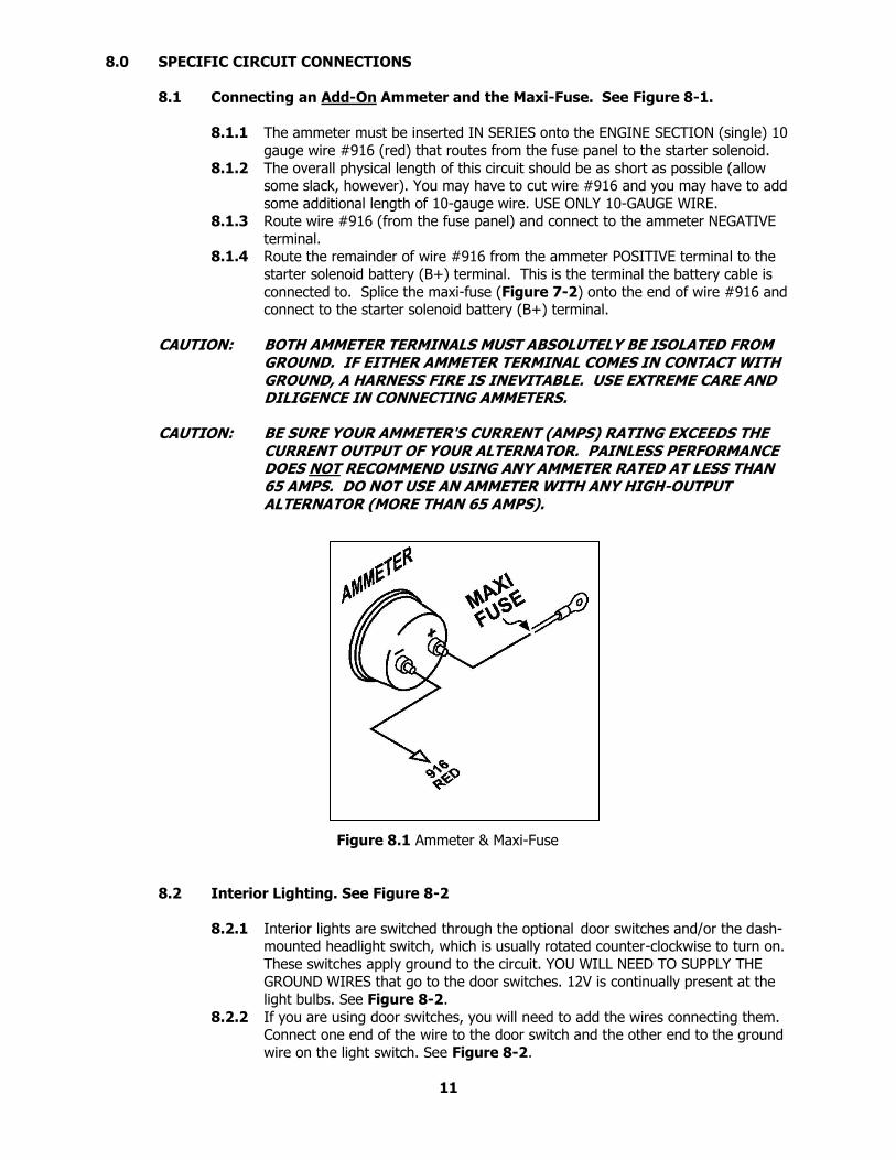
8.1 Connecting an Add-On Ammeter and the Maxi-Fuse. See Figure 8-1.
8.1.1 The ammeter must be inserted IN SERIES onto the ENGINE SECTION (single) 10
gauge wire #916 (red) that routes from the fuse panel to the starter solenoid.
8.1.2 The overall physical length of this circuit should be as short as possible (allow some slack, however). You may have to cut wire #916 and you may have to add
some additional length of 10-gauge wire. USE ONLY 10-GAUGE WIRE. 8.1.3 Route wire #916 (from the fuse panel) and connect to the ammeter NEGATIVE
terminal. 8.1.4 Route the remainder of wire #916 from the ammeter POSITIVE terminal to the
starter solenoid battery (B+) terminal. This is the terminal the battery cable is
connected to. Splice the maxi-fuse (Figure 7-2) onto the end of wire #916 and connect to the starter solenoid battery (B+) terminal.
CAUTION: BOTH AMMETER TERMINALS MUST ABSOLUTELY BE ISOLATED FROM
GROUND. IF EITHER AMMETER TERMINAL COMES IN CONTACT WITH GROUND, A HARNESS FIRE IS INEVITABLE. USE EXTREME CARE AND DILIGENCE IN CONNECTING AMMETERS.
CAUTION: BE SURE YOUR AMMETER'S CURRENT (AMPS) RATING EXCEEDS THE
CURRENT OUTPUT OF YOUR ALTERNATOR. PAINLESS PERFORMANCE DOES NOT RECOMMEND USING ANY AMMETER RATED AT LESS THAN 65 AMPS. DO NOT USE AN AMMETER WITH ANY HIGH-OUTPUT ALTERNATOR (MORE THAN 65 AMPS).
Figure 8.1 Ammeter & Maxi-Fuse
8.2 Interior Lighting. See Figure 8-2
8.2.1 Interior lights are switched through the optional door switches and/or the dash-mounted headlight switch, which is usually rotated counter-clockwise to turn on.
These switches apply ground to the circuit. YOU WILL NEED TO SUPPLY THE GROUND WIRES that go to the door switches. 12V is continually present at the
light bulbs. See Figure 8-2.
8.2.2 If you are using door switches, you will need to add the wires connecting them. Connect one end of the wire to the door switch and the other end to the ground
wire on the light switch. See Figure 8-2.
11 Figure 8-2 Interior Lighting
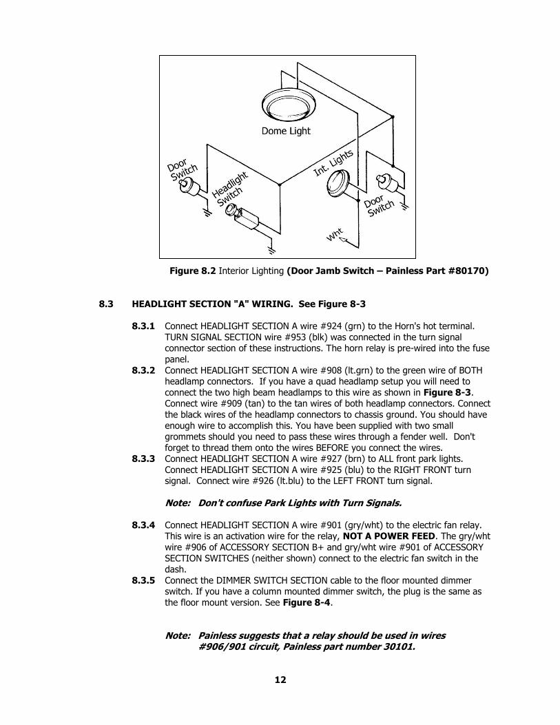
Figure 8.2 Interior Lighting (Door Jamb Switch – Painless Part #80170)
8.3 HEADLIGHT SECTION "A" WIRING. See Figure 8-3
8.3.1 Connect HEADLIGHT SECTION A wire #924 (grn) to the Horn's hot terminal.
TURN SIGNAL SECTION wire #953 (blk) was connected in the turn signal connector section of these instructions. The horn relay is pre-wired into the fuse
panel.
8.3.2 Connect HEADLIGHT SECTION A wire #908 (lt.grn) to the green wire of BOTH headlamp connectors. If you have a quad headlamp setup you will need to
connect the two high beam headlamps to this wire as shown in Figure 8-3. Connect wire #909 (tan) to the tan wires of both headlamp connectors. Connect
the black wires of the headlamp connectors to chassis ground. You should have
enough wire to accomplish this. You have been supplied with two small grommets should you need to pass these wires through a fender well. Don't
forget to thread them onto the wires BEFORE you connect the wires. 8.3.3 Connect HEADLIGHT SECTION A wire #927 (brn) to ALL front park lights.
Connect HEADLIGHT SECTION A wire #925 (blu) to the RIGHT FRONT turn signal. Connect wire #926 (lt.blu) to the LEFT FRONT turn signal.
Note: Don't confuse Park Lights with Turn Signals.
8.3.4 Connect HEADLIGHT SECTION A wire #901 (gry/wht) to the electric fan relay. This wire is an activation wire for the relay, NOT A POWER FEED. The gry/wht
wire #906 of ACCESSORY SECTION B+ and gry/wht wire #901 of ACCESSORY
SECTION SWITCHES (neither shown) connect to the electric fan switch in the dash.
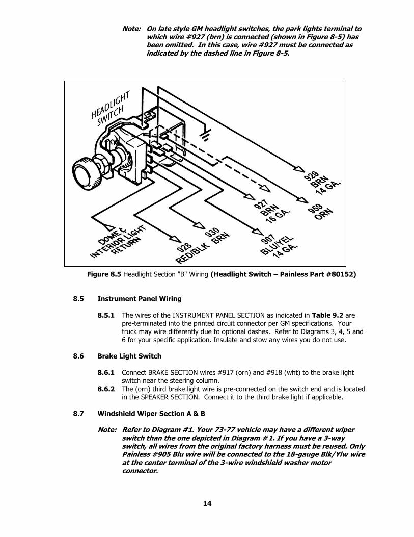
8.3.5 Connect the DIMMER SWITCH SECTION cable to the floor mounted dimmer switch. If you have a column mounted dimmer switch, the plug is the same as
the floor mount version. See Figure 8-4.
Note: Painless suggests that a relay should be used in wires #906/901 circuit, Painless part number 30101.
12
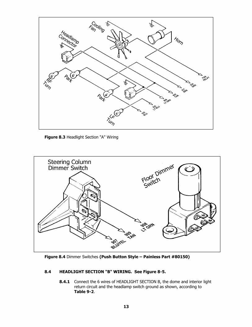
Figure 8.3 Headlight Section "A" Wiring
Figure 8.4 Dimmer Switches (Push Button Style – Painless Part #80150)
8.4 HEADLIGHT SECTION "B" WIRING. See Figure 8-5.
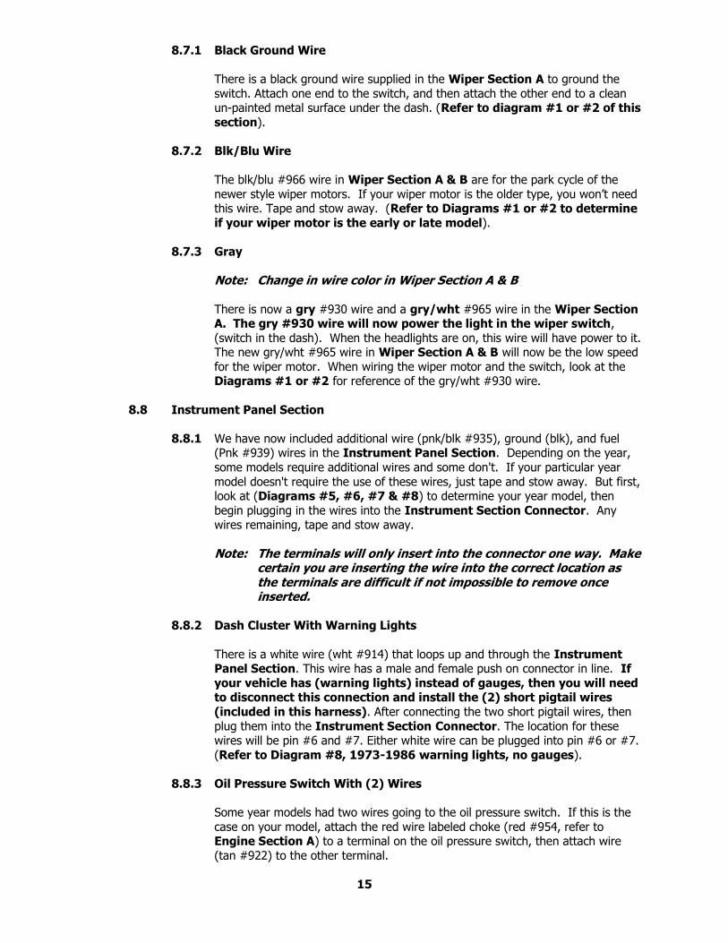
8.4.1 Connect the 6 wires of HEADLIGHT SECTION B, the dome and interior light
return circuit and the headlamp switch ground as shown, according to Table 9-2.
13
Note: On late style GM headlight switches, the park lights terminal to which wire #927 (brn) is connected (shown in Figure 8-5) has been omitted. In this case, wire #927 must be connected as indicated by the dashed line in Figure 8-5.
Figure 8.5 Headlight Section "B" Wiring (Headlight Switch – Painless Part #80152)
8.5 Instrument Panel Wiring
8.5.1 The wires of the INSTRUMENT PANEL SECTION as indicated in Table 9.2 are pre-terminated into the printed circuit connector per GM specifications. Your
truck may wire differently due to optional dashes. Refer to Diagrams 3, 4, 5 and 6 for your specific application. Insulate and stow any wires you do not use.
8.6 Brake Light Switch
8.6.1 Connect BRAKE SECTION wires #917 (orn) and #918 (wht) to the brake light switch near the steering column.
8.6.2 The (orn) third brake light wire is pre-connected on the switch end and is located in the SPEAKER SECTION. Connect it to the third brake light if applicable.
8.7 Windshield Wiper Section A & B
Note: Refer to Diagram #1. Your 73-77 vehicle may have a different wiper switch than the one depicted in Diagram # 1. If you have a 3-way switch, all wires from the original factory harness must be reused. Only Painless #905 Blu wire will be connected to the 18-gauge Blk/Ylw wire at the center terminal of the 3-wire windshield washer motor connector.
14
8.7.1 Black Ground Wire
There is a black ground wire supplied in the Wiper Section A to ground the
switch. Attach one end to the switch, and then attach the other end to a clean un-painted metal surface under the dash. (Refer to diagram #1 or #2 of this
section).
8.7.2 Blk/Blu Wire
The blk/blu #966 wire in Wiper Section A & B are for the park cycle of the
newer style wiper motors. If your wiper motor is the older type, you won’t need this wire. Tape and stow away. (Refer to Diagrams #1 or #2 to determine
if your wiper motor is the early or late model).
8.7.3 Gray
Note: Change in wire color in Wiper Section A & B
There is now a gry #930 wire and a gry/wht #965 wire in the Wiper Section A. The gry #930 wire will now power the light in the wiper switch,
(switch in the dash). When the headlights are on, this wire will have power to it. The new gry/wht #965 wire in Wiper Section A & B will now be the low speed
for the wiper motor. When wiring the wiper motor and the switch, look at the Diagrams #1 or #2 for reference of the gry/wht #930 wire.
8.8 Instrument Panel Section
8.8.1 We have now included additional wire (pnk/blk #935), ground (blk), and fuel (Pnk #939) wires in the Instrument Panel Section. Depending on the year,
some models require additional wires and some don't. If your particular year
model doesn't require the use of these wires, just tape and stow away. But first, look at (Diagrams #5, #6, #7 & #8) to determine your year model, then
begin plugging in the wires into the Instrument Section Connector. Any wires remaining, tape and stow away.
Note: The terminals will only insert into the connector one way. Make certain you are inserting the wire into the correct location as the terminals are difficult if not impossible to remove once inserted.
8.8.2 Dash Cluster With Warning Lights
There is a white wire (wht #914) that loops up and through the Instrument Panel Section. This wire has a male and female push on connector in line. If
your vehicle has (warning lights) instead of gauges, then you will need to disconnect this connection and install the (2) short pigtail wires
(included in this harness). After connecting the two short pigtail wires, then
plug them into the Instrument Section Connector. The location for these wires will be pin #6 and #7. Either white wire can be plugged into pin #6 or #7.
(Refer to Diagram #8, 1973-1986 warning lights, no gauges).
8.8.3 Oil Pressure Switch With (2) Wires
Some year models had two wires going to the oil pressure switch. If this is the
case on your model, attach the red wire labeled choke (red #954, refer to Engine Section A) to a terminal on the oil pressure switch, then attach wire
(tan #922) to the other terminal.
15
8.8.4 Black Ground Wire
We have included several short black (jumper) wires in the Instrument Panel
Section. One end of this wire (approx. 15") will need to be attached to a clean un-painted metal surface under the dash. On the other end there will be short
jumper wires. They will need to be plugged into the Instrument Section
Connector. (Refer to Diagram #5, #6, #7 or #8 for pin placement). If only one wire is used, then tape and stow away the other.
8.9 Heat Only
8.9.1 Units with heat only will connect wires brn #904 and brn/wht #967 together in
AC Section A using a blue 1/4" push on connector. Attach as per Diagram
#9.
Note: The tan wire #969 will be omitted at the switch and the resistor. Tape and stow away. The grn wire #902 will also be omitted in Engine Section B and in AC Section B, because there is no compressor. Tape and stow away.
8.10 A/C Section "A" (see Diagrams 9 & 10, Pg 28-29)
8.10.1 Blower Motor Relay Connector (connector w/pur, red, blk, blu & orn wires)
This connector will plug into most models that have a blower motor relay, however, some early models (1973-1978) didn't use a blower motor relay.
Without this relay, the current draw is too much for the blower motor switch (causing the Hi-Speed to burn out in the switch). We have pre-wired this
blower motor relay connector into the harness for safety. If you don't presently
have a blower motor relay on your truck, then one will need to be purchased at your local parts store.
8.11 A/C Section "B"
8.11.1 Blower Resistor Connector
The blower resistor (located on top of the ac/heat box under the hood) has 4 pins on it. Just plug in the blower resistor connector and you are done. If the
blower resistor has only 3 pins, then cut off the connector (connector with brn/wht, tan, blu, lt.blu) and wire as followed. (Refer to Diagram #9). Use
the blue push on connectors supplied in the parts kit.
Note: The brn/wht wire will not be used with the 3-pin resistor. It is
a B+ positive wire and will need to be taped off and stowed away.
9.0 WIRE CONNECTION INDEX AND FUSE REQUIREMENTS
9.1 Wire Connection Index
In each section, connect the wire, as identified by its wire color, to the appropriate item
in the CONNECT TO column. Pay close attention to the Notes in this section, as identified by a number in parenthesis such as the one at the end of this sentence. (1)
16
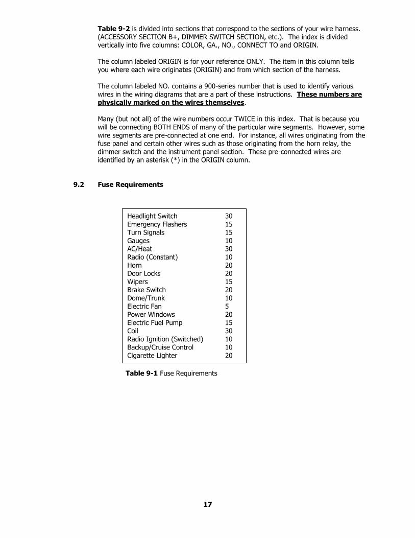
Table 9-2 is divided into sections that correspond to the sections of your wire harness.
(ACCESSORY SECTION B+, DIMMER SWITCH SECTION, etc.). The index is divided vertically into five columns: COLOR, GA., NO., CONNECT TO and ORIGIN.
The column labeled ORIGIN is for your reference ONLY. The item in this column tells
you where each wire originates (ORIGIN) and from which section of the harness.
The column labeled NO. contains a 900-series number that is used to identify various
wires in the wiring diagrams that are a part of these instructions. These numbers are physically marked on the wires themselves.
Many (but not all) of the wire numbers occur TWICE in this index. That is because you
will be connecting BOTH ENDS of many of the particular wire segments. However, some
wire segments are pre-connected at one end. For instance, all wires originating from the fuse panel and certain other wires such as those originating from the horn relay, the
dimmer switch and the instrument panel section. These pre-connected wires are identified by an asterisk (*) in the ORIGIN column.
9.2 Fuse Requirements
Table 9-1 Fuse Requirements
17
Headlight Switch 30
Emergency Flashers 15 Turn Signals 15
Gauges 10 AC/Heat 30
Radio (Constant) 10
Horn 20 Door Locks 20
Wipers 15 Brake Switch 20
Dome/Trunk 10
Electric Fan 5 Power Windows 20
Electric Fuel Pump 15 Coil 30
Radio Ignition (Switched) 10 Backup/Cruise Control 10
Cigarette Lighter 20
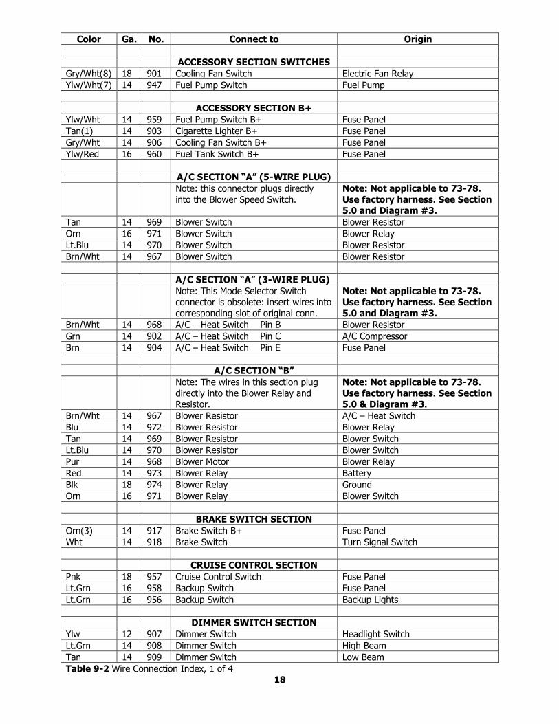
Color Ga. No. Connect to Origin
ACCESSORY SECTION SWITCHES
Gry/Wht(8) 18 901 Cooling Fan Switch Electric Fan Relay
Ylw/Wht(7) 14 947 Fuel Pump Switch Fuel Pump
ACCESSORY SECTION B+
Ylw/Wht 14 959 Fuel Pump Switch B+ Fuse Panel
Tan(1) 14 903 Cigarette Lighter B+ Fuse Panel
Gry/Wht 14 906 Cooling Fan Switch B+ Fuse Panel
Ylw/Red 16 960 Fuel Tank Switch B+ Fuse Panel
A/C SECTION “A” (5-WIRE PLUG)
Note: this connector plugs directly
into the Blower Speed Switch.
Note: Not applicable to 73-78.
Use factory harness. See Section 5.0 and Diagram #3.
Tan 14 969 Blower Switch Blower Resistor
Orn 16 971 Blower Switch Blower Relay
Lt.Blu 14 970 Blower Switch Blower Resistor
Brn/Wht 14 967 Blower Switch Blower Resistor
A/C SECTION “A” (3-WIRE PLUG)
Note: This Mode Selector Switch
connector is obsolete: insert wires into
corresponding slot of original conn.
Note: Not applicable to 73-78.
Use factory harness. See Section
5.0 and Diagram #3.
Brn/Wht 14 968 A/C – Heat Switch Pin B Blower Resistor
Grn 14 902 A/C – Heat Switch Pin C A/C Compressor
Brn 14 904 A/C – Heat Switch Pin E Fuse Panel
A/C SECTION “B”
Note: The wires in this section plug
directly into the Blower Relay and Resistor.
Note: Not applicable to 73-78.
Use factory harness. See Section 5.0 & Diagram #3.
Brn/Wht 14 967 Blower Resistor A/C – Heat Switch
Blu 14 972 Blower Resistor Blower Relay
Tan 14 969 Blower Resistor Blower Switch
Lt.Blu 14 970 Blower Resistor Blower Switch
Pur 14 968 Blower Motor Blower Relay
Red 14 973 Blower Relay Battery
Blk 18 974 Blower Relay Ground
Orn 16 971 Blower Relay Blower Switch
BRAKE SWITCH SECTION
Orn(3) 14 917 Brake Switch B+ Fuse Panel
Wht 14 918 Brake Switch Turn Signal Switch
CRUISE CONTROL SECTION
Pnk 18 957 Cruise Control Switch Fuse Panel
Lt.Grn 16 958 Backup Switch Fuse Panel
Lt.Grn 16 956 Backup Switch Backup Lights
DIMMER SWITCH SECTION
Ylw 12 907 Dimmer Switch Headlight Switch
Lt.Grn 14 908 Dimmer Switch High Beam
Tan 14 909 Dimmer Switch Low Beam
Table 9-2 Wire Connection Index, 1 of 4 18
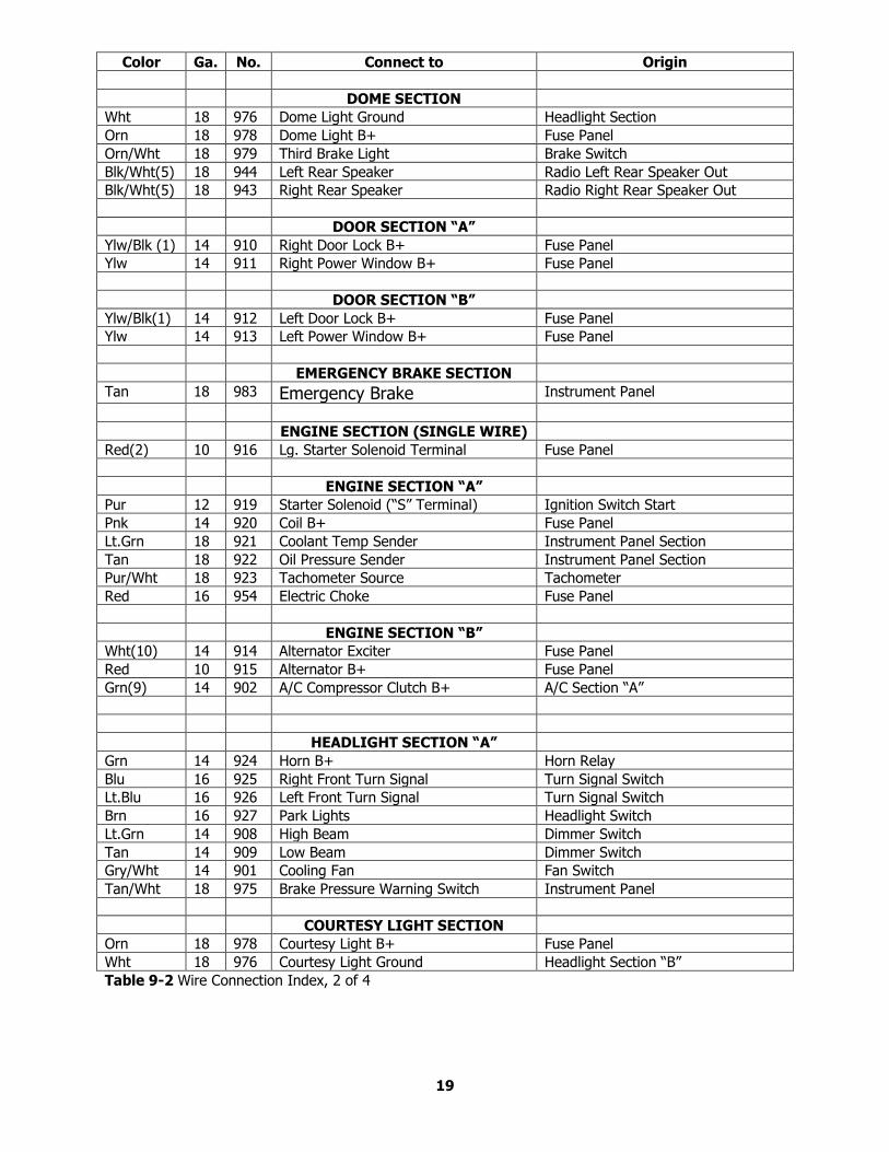
Color Ga. No. Connect to Origin
DOME SECTION
Wht 18 976 Dome Light Ground Headlight Section
Orn 18 978 Dome Light B+ Fuse Panel
Orn/Wht 18 979 Third Brake Light Brake Switch
Blk/Wht(5) 18 944 Left Rear Speaker Radio Left Rear Speaker Out
Blk/Wht(5) 18 943 Right Rear Speaker Radio Right Rear Speaker Out
DOOR SECTION “A”
Ylw/Blk (1) 14 910 Right Door Lock B+ Fuse Panel
Ylw 14 911 Right Power Window B+ Fuse Panel
DOOR SECTION “B”
Ylw/Blk(1) 14 912 Left Door Lock B+ Fuse Panel Ylw 14 913 Left Power Window B+ Fuse Panel
EMERGENCY BRAKE SECTION
Tan 18 983 Emergency Brake Instrument Panel
ENGINE SECTION (SINGLE WIRE)
Red(2) 10 916 Lg. Starter Solenoid Terminal Fuse Panel
ENGINE SECTION “A”
Pur 12 919 Starter Solenoid (“S” Terminal) Ignition Switch Start
Pnk 14 920 Coil B+ Fuse Panel
Lt.Grn 18 921 Coolant Temp Sender Instrument Panel Section
Tan 18 922 Oil Pressure Sender Instrument Panel Section
Pur/Wht 18 923 Tachometer Source Tachometer
Red 16 954 Electric Choke Fuse Panel
ENGINE SECTION “B”
Wht(10) 14 914 Alternator Exciter Fuse Panel Red 10 915 Alternator B+ Fuse Panel Grn(9) 14 902 A/C Compressor Clutch B+ A/C Section “A”
HEADLIGHT SECTION “A”
Grn 14 924 Horn B+ Horn Relay
Blu 16 925 Right Front Turn Signal Turn Signal Switch
Lt.Blu 16 926 Left Front Turn Signal Turn Signal Switch
Brn 16 927 Park Lights Headlight Switch
Lt.Grn 14 908 High Beam Dimmer Switch
Tan 14 909 Low Beam Dimmer Switch
Gry/Wht 14 901 Cooling Fan Fan Switch
Tan/Wht 18 975 Brake Pressure Warning Switch Instrument Panel
COURTESY LIGHT SECTION
Orn 18 978 Courtesy Light B+ Fuse Panel
Wht 18 976 Courtesy Light Ground Headlight Section “B”
Table 9-2 Wire Connection Index, 2 of 4
19
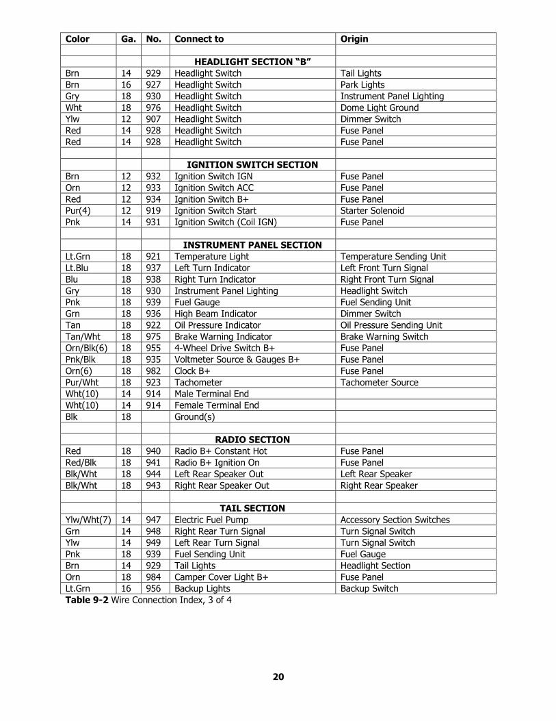
Color Ga. No. Connect to Origin
HEADLIGHT SECTION “B”
Brn 14 929 Headlight Switch Tail Lights
Brn 16 927 Headlight Switch Park Lights
Gry 18 930 Headlight Switch Instrument Panel Lighting
Wht 18 976 Headlight Switch Dome Light Ground
Ylw 12 907 Headlight Switch Dimmer Switch
Red 14 928 Headlight Switch Fuse Panel
Red 14 928 Headlight Switch Fuse Panel
IGNITION SWITCH SECTION
Brn 12 932 Ignition Switch IGN Fuse Panel
Orn 12 933 Ignition Switch ACC Fuse Panel
Red 12 934 Ignition Switch B+ Fuse Panel
Pur(4) 12 919 Ignition Switch Start Starter Solenoid
Pnk 14 931 Ignition Switch (Coil IGN) Fuse Panel
INSTRUMENT PANEL SECTION
Lt.Grn 18 921 Temperature Light Temperature Sending Unit
Lt.Blu 18 937 Left Turn Indicator Left Front Turn Signal
Blu 18 938 Right Turn Indicator Right Front Turn Signal
Gry 18 930 Instrument Panel Lighting Headlight Switch
Pnk 18 939 Fuel Gauge Fuel Sending Unit
Grn 18 936 High Beam Indicator Dimmer Switch
Tan 18 922 Oil Pressure Indicator Oil Pressure Sending Unit
Tan/Wht 18 975 Brake Warning Indicator Brake Warning Switch
Orn/Blk(6) 18 955 4-Wheel Drive Switch B+ Fuse Panel
Pnk/Blk 18 935 Voltmeter Source & Gauges B+ Fuse Panel
Orn(6) 18 982 Clock B+ Fuse Panel
Pur/Wht 18 923 Tachometer Tachometer Source
Wht(10) 14 914 Male Terminal End
Wht(10) 14 914 Female Terminal End
Blk 18 Ground(s)
RADIO SECTION
Red 18 940 Radio B+ Constant Hot Fuse Panel
Red/Blk 18 941 Radio B+ Ignition On Fuse Panel
Blk/Wht 18 944 Left Rear Speaker Out Left Rear Speaker
Blk/Wht 18 943 Right Rear Speaker Out Right Rear Speaker
TAIL SECTION
Ylw/Wht(7) 14 947 Electric Fuel Pump Accessory Section Switches
Grn 14 948 Right Rear Turn Signal Turn Signal Switch
Ylw 14 949 Left Rear Turn Signal Turn Signal Switch
Pnk 18 939 Fuel Sending Unit Fuel Gauge
Brn 14 929 Tail Lights Headlight Section
Orn 18 984 Camper Cover Light B+ Fuse Panel
Lt.Grn 16 956 Backup Lights Backup Switch
Table 9-2 Wire Connection Index, 3 of 4
20
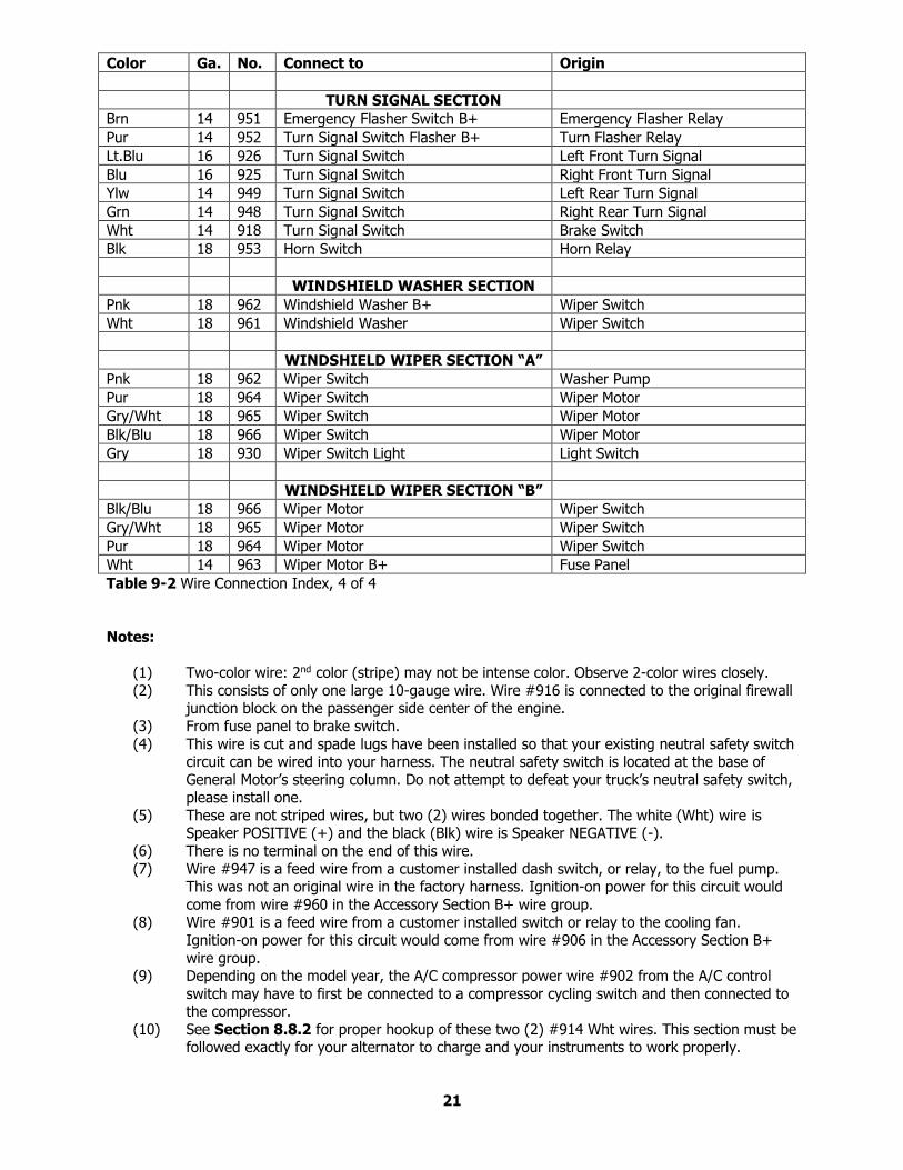
Color Ga. No. Connect to Origin
TURN SIGNAL SECTION
Brn 14 951 Emergency Flasher Switch B+ Emergency Flasher Relay
Pur 14 952 Turn Signal Switch Flasher B+ Turn Flasher Relay
Lt.Blu 16 926 Turn Signal Switch Left Front Turn Signal
Blu 16 925 Turn Signal Switch Right Front Turn Signal
Ylw 14 949 Turn Signal Switch Left Rear Turn Signal
Grn 14 948 Turn Signal Switch Right Rear Turn Signal
Wht 14 918 Turn Signal Switch Brake Switch
Blk 18 953 Horn Switch Horn Relay
WINDSHIELD WASHER SECTION
Pnk 18 962 Windshield Washer B+ Wiper Switch
Wht 18 961 Windshield Washer Wiper Switch
WINDSHIELD WIPER SECTION “A”
Pnk 18 962 Wiper Switch Washer Pump
Pur 18 964 Wiper Switch Wiper Motor
Gry/Wht 18 965 Wiper Switch Wiper Motor
Blk/Blu 18 966 Wiper Switch Wiper Motor
Gry 18 930 Wiper Switch Light Light Switch
WINDSHIELD WIPER SECTION “B”
Blk/Blu 18 966 Wiper Motor Wiper Switch
Gry/Wht 18 965 Wiper Motor Wiper Switch
Pur 18 964 Wiper Motor Wiper Switch
Wht 14 963 Wiper Motor B+ Fuse Panel
Table 9-2 Wire Connection Index, 4 of 4
Notes:
(1) Two-color wire: 2nd color (stripe) may not be intense color. Observe 2-color wires closely.
(2) This consists of only one large 10-gauge wire. Wire #916 is connected to the original firewall junction block on the passenger side center of the engine.
(3) From fuse panel to brake switch.
(4) This wire is cut and spade lugs have been installed so that your existing neutral safety switch circuit can be wired into your harness. The neutral safety switch is located at the base of
General Motor’s steering column. Do not attempt to defeat your truck’s neutral safety switch, please install one.
(5) These are not striped wires, but two (2) wires bonded together. The white (Wht) wire is Speaker POSITIVE (+) and the black (Blk) wire is Speaker NEGATIVE (-).
(6) There is no terminal on the end of this wire.
(7) Wire #947 is a feed wire from a customer installed dash switch, or relay, to the fuel pump. This was not an original wire in the factory harness. Ignition-on power for this circuit would
come from wire #960 in the Accessory Section B+ wire group. (8) Wire #901 is a feed wire from a customer installed switch or relay to the cooling fan.
Ignition-on power for this circuit would come from wire #906 in the Accessory Section B+
wire group. (9) Depending on the model year, the A/C compressor power wire #902 from the A/C control
switch may have to first be connected to a compressor cycling switch and then connected to the compressor.
(10) See Section 8.8.2 for proper hookup of these two (2) #914 Wht wires. This section must be followed exactly for your alternator to charge and your instruments to work properly.
21
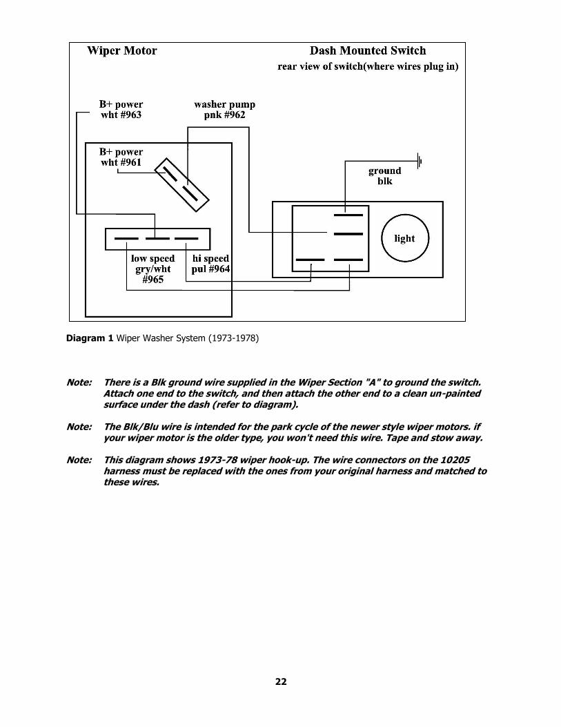
Diagram 1 Wiper Washer System (1973-1978)
Note: There is a Blk ground wire supplied in the Wiper Section "A" to ground the switch.
Attach one end to the switch, and then attach the other end to a clean un-painted surface under the dash (refer to diagram).
Note: The Blk/Blu wire is intended for the park cycle of the newer style wiper motors. if
your wiper motor is the older type, you won't need this wire. Tape and stow away. Note: This diagram shows 1973-78 wiper hook-up. The wire connectors on the 10205
harness must be replaced with the ones from your original harness and matched to these wires.
22
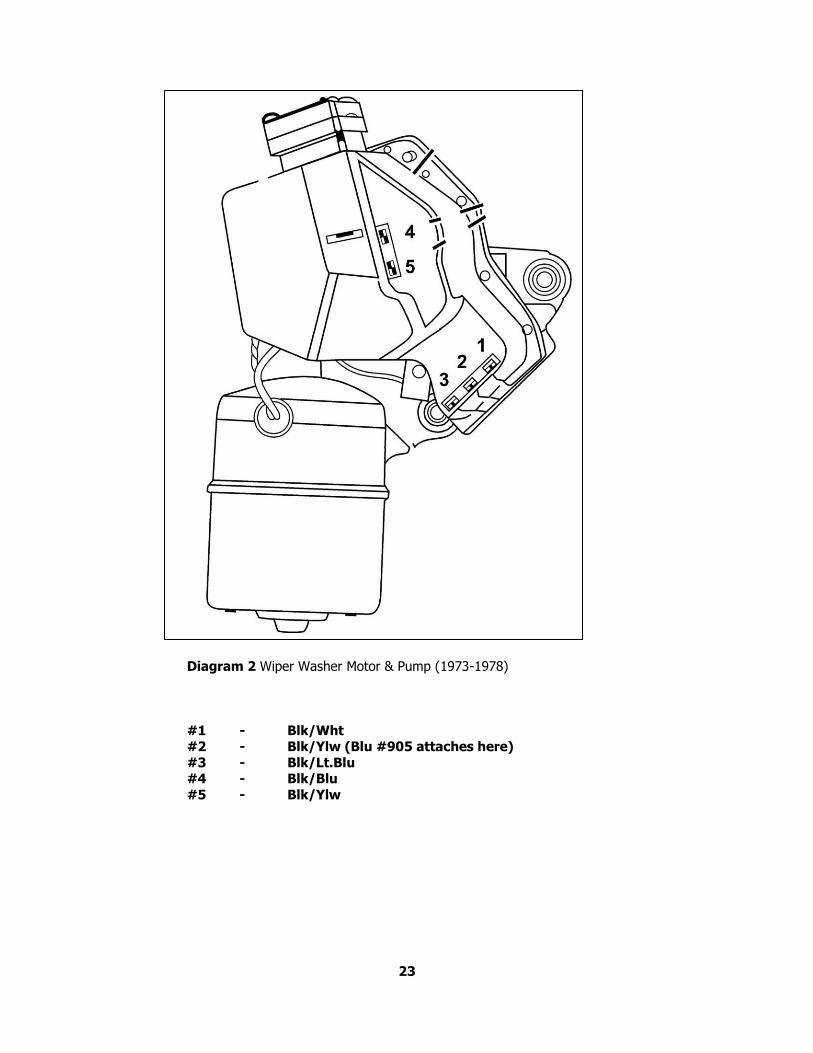
Diagram 2 Wiper Washer Motor & Pump (1973-1978)
#1 - Blk/Wht #2 - Blk/Ylw (Blu #905 attaches here)
#3 - Blk/Lt.Blu #4 - Blk/Blu
#5 - Blk/Ylw
23
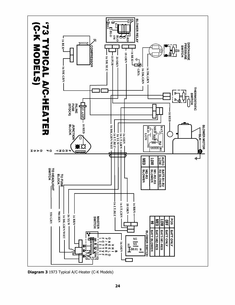
Diagram 3 1973 Typical A/C-Heater (C-K Models)
24
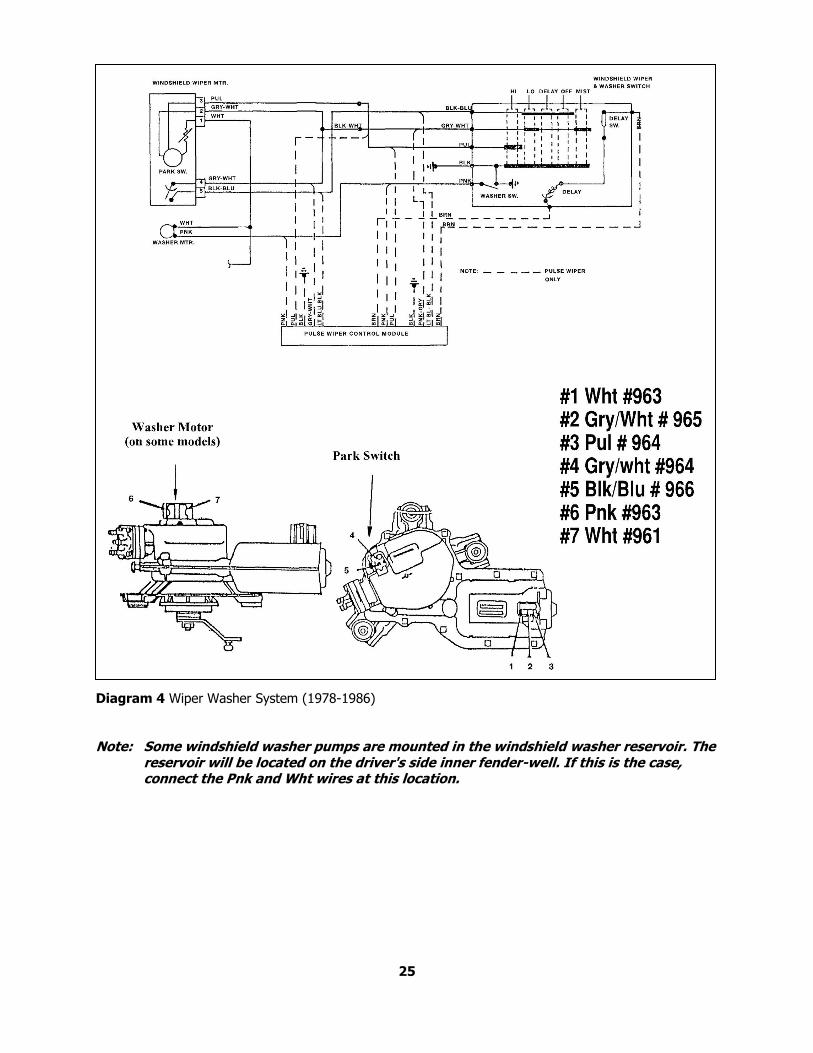
Diagram 4 Wiper Washer System (1978-1986)
Note: Some windshield washer pumps are mounted in the windshield washer reservoir. The
reservoir will be located on the driver's side inner fender-well. If this is the case, connect the Pnk and Wht wires at this location.
25
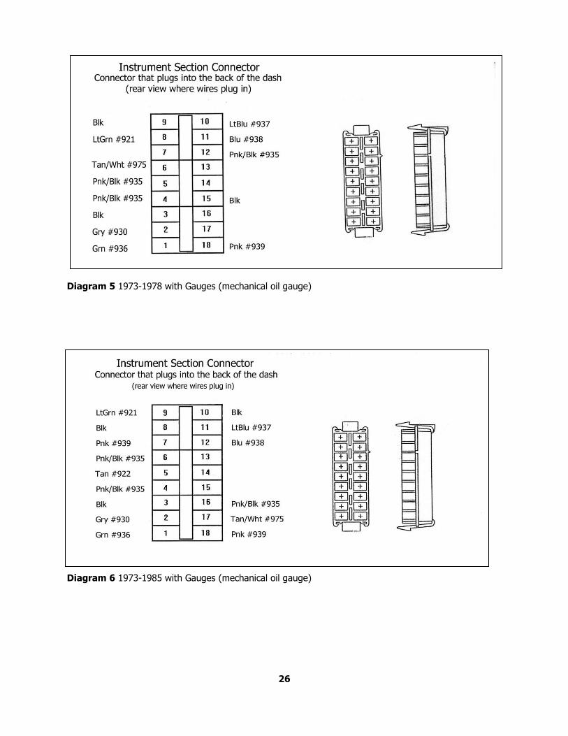
Diagram 5 1973-1978 with Gauges (mechanical oil gauge)
Diagram 6 1973-1985 with Gauges (mechanical oil gauge)
26
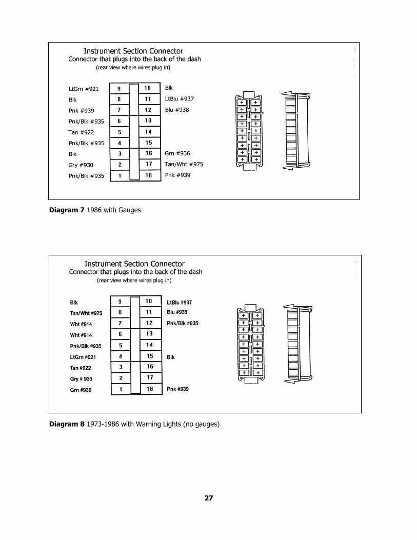
Diagram 7 1986 with Gauges
Diagram 8 1973-1986 with Warning Lights (no gauges)
27
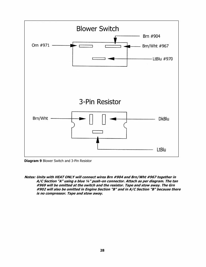
Diagram 9 Blower Switch and 3-Pin Resistor
Notes: Units with HEAT ONLY will connect wires Brn #904 and Brn/Wht #967 together in
A/C Section "A" using a blue ¼" push-on connector. Attach as per diagram. The tan #969 will be omitted at the switch and the resistor. Tape and stow away. The Grn #902 will also be omitted in Engine Section "B" and in A/C Section "B" because there is no compressor. Tape and stow away.
28
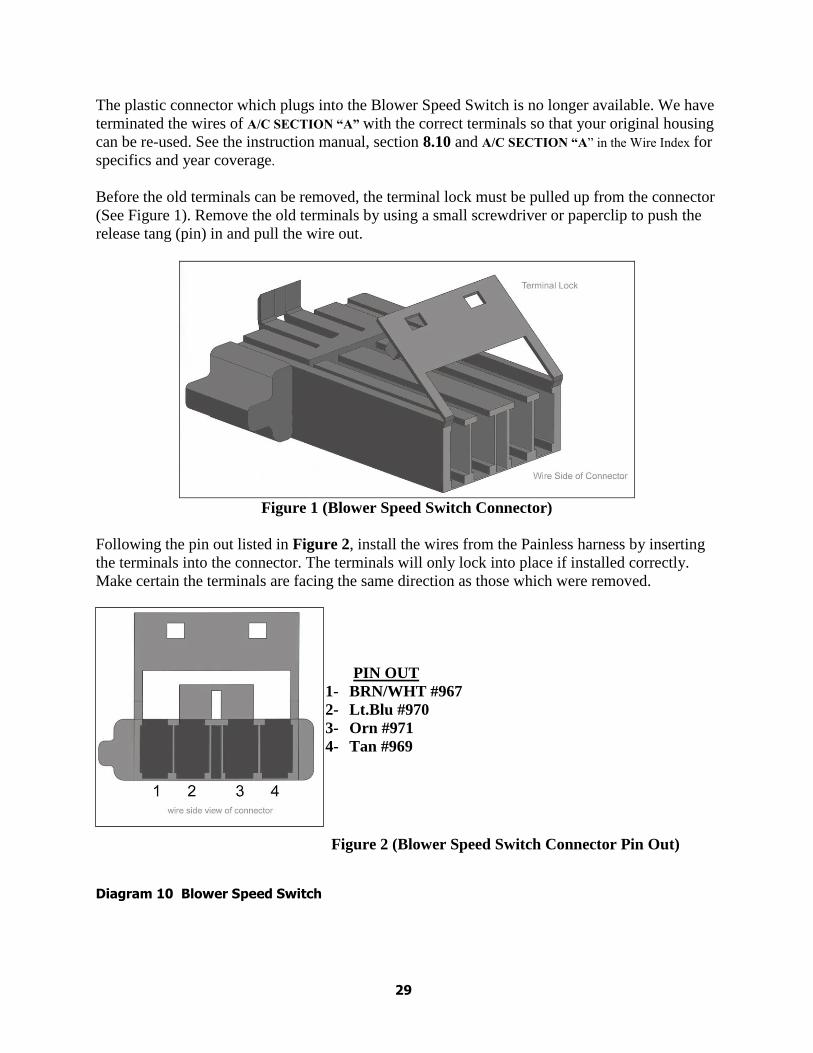
The plastic connector which plugs into the Blower Speed Switch is no longer available. We have
terminated the wires of A/C SECTION “A” with the correct terminals so that your original housing
can be re-used. See the instruction manual, section 8.10 and A/C SECTION “A” in the Wire Index for
specifics and year coverage.
Before the old terminals can be removed, the terminal lock must be pulled up from the connector
(See Figure 1). Remove the old terminals by using a small screwdriver or paperclip to push the
release tang (pin) in and pull the wire out.
Figure 1 (Blower Speed Switch Connector)
Following the pin out listed in Figure 2, install the wires from the Painless harness by inserting
the terminals into the connector. The terminals will only lock into place if installed correctly.
Make certain the terminals are facing the same direction as those which were removed.
PIN OUT
1- BRN/WHT #967
2- Lt.Blu #970
3- Orn #971
4- Tan #969
Figure 2 (Blower Speed Switch Connector Pin Out)
Diagram 10 Blower Speed Switch
29

Painless Performance Limited Warranty
and Return Policy
Chassis harnesses , fuel injection And Striker ColdShot units harnesses are covered under a
lifetime warranty.
All other products manufactured and/or sold by Painless Performance are warranted to the
original purchaser to be free from defects in material and workmanship under normal use.
Painless Performance will repair or replace defective products without charge during the first 12
months from the purchase date. No products will be considered for warranty without a copy of
the purchase receipt showing the sellers name, address and date of purchase. You must return the
product to the dealer you purchased it from to initiate warranty procedures.
NOTES
30