Embed Size (px)
Citation preview

Wire Harness Installation
Instructions
For Installing:
Part #60510 & 60511 Ford 5.0L 1986-93 Wiring Harness
Manual #90518
Perfect Performance Products, LLC
Painless Performance Products Division 2501 Ludelle Street, Fort Worth, Texas 76105-1036
(800) 423-9696

We have attempted to provide you with as accurate instructions as possible, and are always concerned about corrections or improvements that can be made. If you have found any errors or omissions, or if you simply have comments or suggestions concerning these instructions, please write us at the address on the cover and let us know about them. Or, better yet, send us a fax at (817) 244-4024. We sincerely appreciate your business. For Technical Questions
E-mail: [email protected]
Tech Line: 800-423-9696 Perfect Performance Products, LLC shall in no event be liable in contract or tort (including negligence) for special, indirect, incidental or consequential damages, such as, but not limited to, loss of property damage, or any other damages, costs or expenses which might be claimed as the result of the use or failure of the goods sold hereby, except only the cost of repair or replacement.
P/N 90518 Painless Wiring Manual August 2006
Copyright © 2001 by Perfect Performance Products, LLC
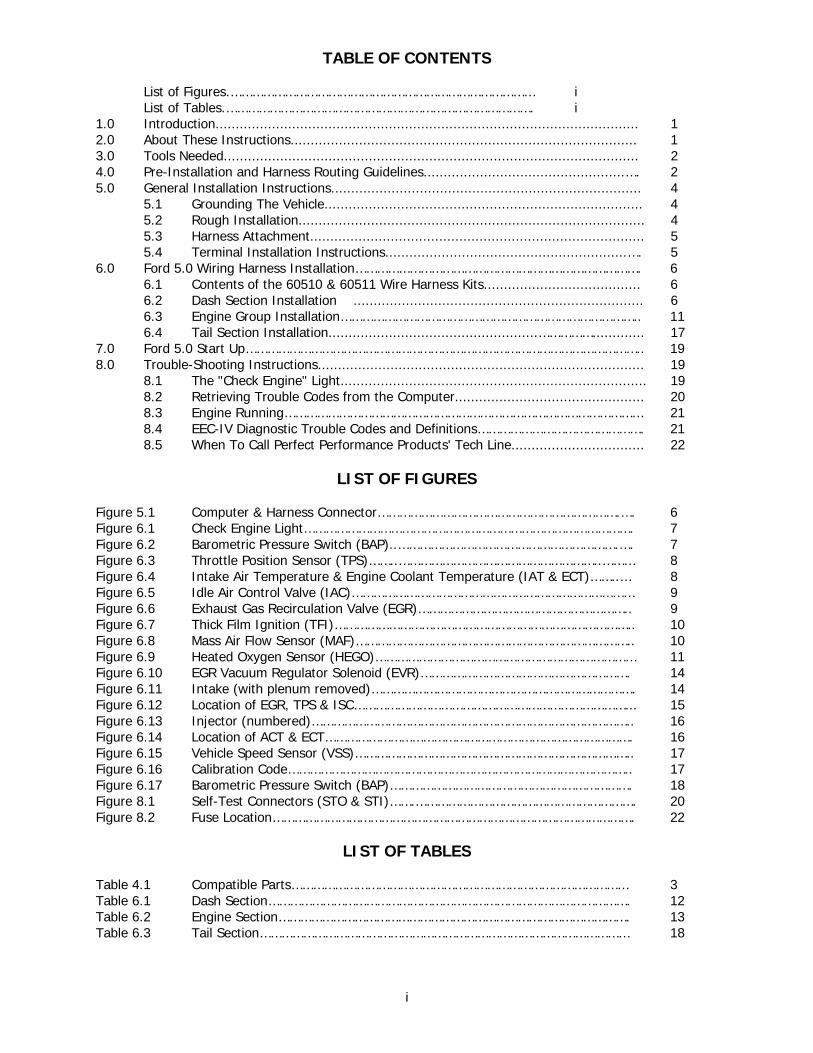
TABLE OF CONTENTS List of Figures.………………………………………………………………………… i List of Tables.…………………………………………………………………………. i
1.0 Introduction......................................................................................................... 1 2.0 About These Instructions...................................................................................... 1 3.0 Tools Needed....................................................................................................... 2 4.0 Pre-Installation and Harness Routing Guidelines..................................................…. 2 5.0 General Installation Instructions............................................................................. 4
5.1 Grounding The Vehicle............................................................................... 4 5.2 Rough Installation...................................................................................... 4 5.3 Harness Attachment................................................................................... 5 5.4 Terminal Installation Instructions............................................................…. 5
6.0 Ford 5.0 Wiring Harness Installation……………………………………………………………………. 6 6.1 Contents of the 60510 & 60511 Wire Harness Kits....................................... 6 6.2 Dash Section Installation ........................................................................ 6 6.3 Engine Group Installation……………………………………………………………………….. 11 6.4 Tail Section Installation....................................................……………............. 17
7.0 Ford 5.0 Start Up……………………………………………………………………………………………….. 19 8.0 Trouble-Shooting Instructions................................................................................. 19
8.1 The "Check Engine" Light............................................................................ 19 8.2 Retrieving Trouble Codes from the Computer............................................... 20 8.3 Engine Running……………………………………………………………………………………… 21 8.4 EEC-IV Diagnostic Trouble Codes and Definitions………………………………………. 21 8.5 When To Call Perfect Performance Products' Tech Line................................. 22
LIST OF FIGURES Figure 5.1 Computer & Harness Connector………………………………………………………….…. 6 Figure 6.1 Check Engine Light………………………………………………………………………………. 7 Figure 6.2 Barometric Pressure Switch (BAP)..…………………………………………………….…. 7 Figure 6.3 Throttle Position Sensor (TPS)……..………………………………………………..……… 8 Figure 6.4 Intake Air Temperature & Engine Coolant Temperature (IAT & ECT)……..… 8 Figure 6.5 Idle Air Control Valve (IAC)…………………………………………………………………… 9 Figure 6.6 Exhaust Gas Recirculation Valve (EGR)………………………………………………….. 9 Figure 6.7 Thick Film Ignition (TFI)……………………………………………………………………….. 10 Figure 6.8 Mass Air Flow Sensor (MAF)………………………………………………………………….. 10 Figure 6.9 Heated Oxygen Sensor (HEGO)……………………………………………………………… 11 Figure 6.10 EGR Vacuum Regulator Solenoid (EVR)…………………………………………………. 14 Figure 6.11 Intake (with plenum removed)………………………………………………………………. 14 Figure 6.12 Location of EGR, TPS & ISC…………………………………………………………………... 15 Figure 6.13 Injector (numbered)…………………………………………………………………………….. 16 Figure 6.14 Location of ACT & ECT…………………………………………………………………………. 16 Figure 6.15 Vehicle Speed Sensor (VSS)………………………………………………………………….. 17 Figure 6.16 Calibration Code………………………………………………………………………………….. 17 Figure 6.17 Barometric Pressure Switch (BAP)…………………………………………………………. 18 Figure 8.1 Self-Test Connectors (STO & STI)…….……………………………………………………. 20 Figure 8.2 Fuse Location………………………………………………………………………………………. 22
LIST OF TABLES Table 4.1 Compatible Parts………………………………………………………………………………… 3 Table 6.1 Dash Section………………………………………………………………………………………. 12 Table 6.2 Engine Section……………………………………………………………………………………. 13 Table 6.3 Tail Section………………………………………………………………………………………… 18
i
1.0 INTRODUCTION
You have purchased what we at Perfect Performance Products, LLC believe to be the most up-to- date and easiest-to-install automotive fuel injection harness on the market. It is designed for easy installation, even if you have no electrical experience.
This harness is based on the 1993 Ford Mustang setup and is designed to be a complete wiring system for the fuel injection system on Ford 5.0L fuel injection engines with (Mass Air Flow System). This harness includes all wiring that is needed by the computer to run and control the fuel injection system. Note: `94 & 95 engines will require switching the distributor to an `86-93 type and modifying the TPS wiring. Note: `86 & 87 engines can be used if converted to a Mass Air Flow System. The change from Speed Density to Mass Air Flow would require changing the ECM and adding a MAF sensor. See Table 4.1 on page 3
Usually, the Computer, Fuse block and Relays can easily be mounted under the dash. Most of the wiring in the harness has been pre-terminated to the proper connector and all wire is rated at 125C and has been Ford color-coded.
These fuel system harnesses have been divided into three major groups: ENGINE GROUP Includes wiring for the fuel injectors, distributor, sensors,
and constant power wire.
DASH GROUP Includes ignition feed wire, STO and STI (self test) connectors, check-engine light, and the barometric pressure
connector.
TAIL SECTION Power wire for fuel pump and VSS. 2.0 ABOUT THESE INSTRUCTIONS
These instructions provide information for the installation of the 60510 Fuel Injection Wire Harness Kit. The contents of these instructions are divided into major Sections, as follows:
1.0 Introduction 2.0 About These Instructions 3.0 Tools Needed 4.0 Pre-Installation and Harness Routing Guidelines 5.0 General Installation Instructions 6.0 60510 & 60511 Fuel Injection Harness Kit 7.0 Start Up 8.0 Trouble Shooting Instructions and Trouble Codes
Sections are further divided into Paragraphs and Steps. Throughout, the Figure numbers refer to illustrations and the Table numbers refer to information in table form. These are located in or near the sections or paragraphs to which they correspond. Always pay careful attention to any Notes or any text labeled CAUTION.
1
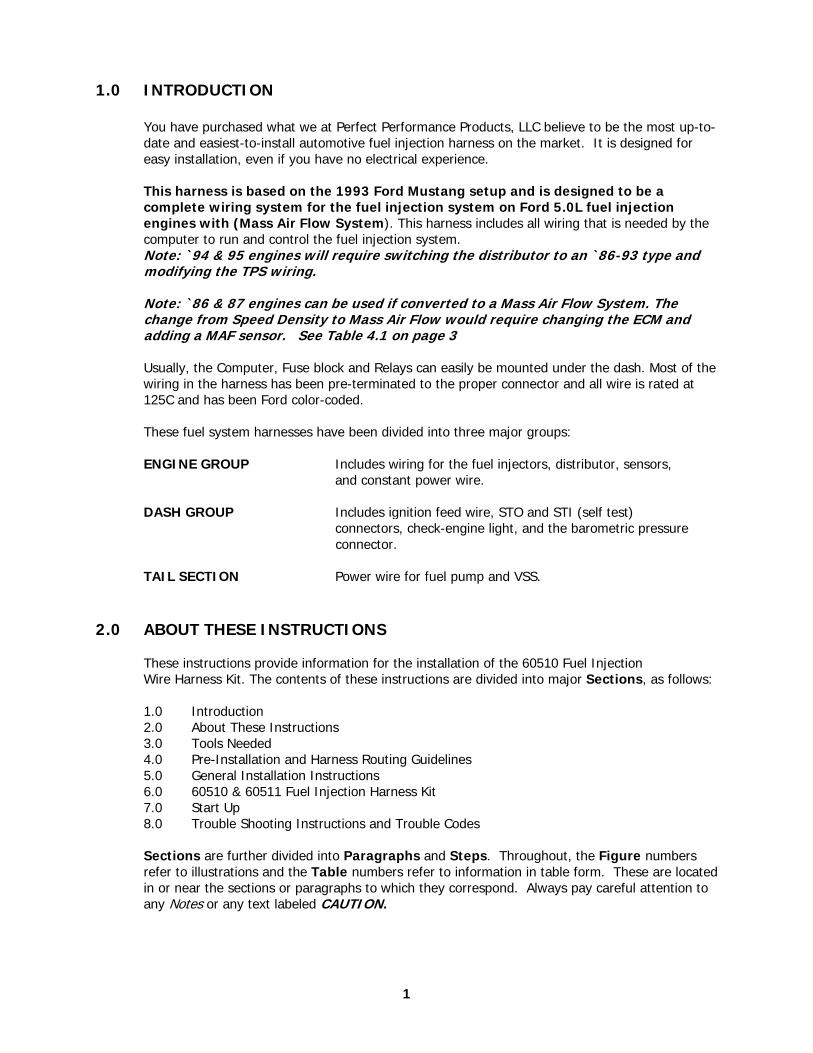
3.0 TOOLS NEEDED
In addition to your regular tools, you will need, at least, the following:
Crimping Tool Note: Use a quality tool to avoid over-crimping. Wire Stripper Continuity Tester Caution: Do not use a test light to test the computer or sensor
wiring or you will damage the computer. Electric Drill 1-5/8" Hole saw (for the rubber grommet in the firewall)
4.0 PRE-INSTALLATION AND HARNESS ROUTING GUIDELINES
The installation of your harness kit consists mainly of two parts:
• The physical routing, positioning, and securing of the harness, wire groups, and individual wires and connectors.
• The proper electrical connection of the individual circuits.
These two major tasks are not separate steps, but are integrated together. That is, you will route some wires and make some connections, route some more wires and make some more connections.
We cannot tell you how to physically route the harness in your vehicle. That depends a great
deal upon the particular make of vehicle and to what extent you want to secure and conceal the harness. We do offer some general guidelines and routing practices starting in Paragraph
4.3, GENERAL installation instructions in Section 5.0, and precise instructions concerning the electrical connections you will have to make beginning in Section 6.0. To help you begin
thinking through the installation of your wire harness, read the following sections:
4.1 You should get to know the particular engine that you are using: • Ford Fuel Injection System with a mass airflow (MAF) sensor. The 60510 &
60511 harness will support the Mass Airflow (MAF) and the Thick Film Ignition (TFI) module in addition to the other wiring common to the fuel injection systems.
4.2 Painless recommends the use of the following parts. See Table 4.1 on page 3. These
will meet all requirements and are compatible with the Painless harnesses. The following numbers given are Ford or Motorcraft part numbers. The main computer part numbers are REQUIRED for use with our harnesses.
Note: Calibration numbers: If the calibration is known, it is best and
recommended that all part have matching calibration. This is for the best performance.
The computer part numbers shown in the compatible parts list in Table 4.1 are required part numbers for that application. The use of any other computer may damage the computer, harness or both. Use of the wrong computer will almost certainly cause problems. The programming in the computer for a manual transmission is slightly different than that of an automatic. Please double check to be sure that you have the correct computer part number (it is shown as a service number on the computer itself). The rest of the part numbers shown are for your information only.
2
4.3 Familiarize yourself with the harness by locating each of the harness groups and by looking at the connectors on the wire ends.
4.4 Decide where and how the computer and sensors will be mounted. PPP wire harness kits
are designed to mount both, under the dash or in the lower kick panel on the right side. 4.5 A good exercise is to lay out the wire harness on the floor beside your vehicle and
identify all the connectors and wires. The harness must be routed from the inside of the vehicle out to the engine compartment.
4.6 You will want to route the harness through and around open areas. Inside edges provide
extra protection from hazards and also provide places for tie wraps, clips and other support.
4.7 Route the harness away from sharp edges, exhaust pipes, and the hood, trunk, and door
hinges. 4.8 Plan where harness supports will be located. Use a support approximately every 6 inches
unless the harness routes under the floor carpet. 4.9 Allow enough slack in the harness at places where movement could possibly occur (body
to frame, frame to engine, etc.).
4.10 The wires should be bundled into harness groups. Use tape, nylon ties or split loom.
Table 4.1 Compatible Parts (Main Computer comes with MAF sensor)
3
60510 & 60511 FUEL INJECTION KIT
Description Ford Motorcraft Main Computer (auto transmission) M-12071-G302 (Ford Racing) (manual transmission) M-12071-F302 (Ford Racing) Thick Film Ignition module (TFI) E6SZ-12A297-A DY-504 Throttle Position Sensor E6AF-9B989-CA CX-1133 Barometric Absolute Pressure Sensor E7EF-12A644-A2A DY-530 Intake Air Temperature Sensor F2DF-12A697-AA DY-674 Fuel Pump Relay 87452 (Hella) EEC Power Relay................... 87452 (Hella) Engine Coolant Temperature Sensor F2AF-12A648-AA DY-681 Heated Exhaust Gas Oxygen Sensor (HEGO) E7TF-9F472-AA DY-605 Vehicle Speed Sensor E3AZ-9E731-A E.G.R. Valve E7PE-9H473-H2A CX-1230A E.G.R. Sensor F2ZE-9G428-AA CX-1464 E.G.R Valve Gasket CG-697 EGR Vacuum Regulator (EVR) E63Z-9J459-A Note: The main computer is from FORD RACING. Relays are from HELLA. If you have a used computer take the time to call your local Ford Parts Dealer to verify you have the proper PCM. If you know the calibration of your engine it is best to buy parts with the same code.
5.0 GENERAL INSTALLATION INSTRUCTIONS
CAUTION: • Do not disconnect the battery or the computer connector(s) while the ignition
is on. • Do not short any wire in this harness to ground (with the exception of labeled
ground wires) or damage to the computer will result. • Giving or receiving a jump-start may damage the computer. • Do not use a test light when testing computer sensors or computer circuits.
Damage to the computer will result! • When routing the wires for the vehicle speed sensor (if used) make certain
that they are at least 12 inches away from any ignition wiring (spark plug wires, etc.).
Notes: • All of the adapters, listed in the manual, are included in the wiring kit. You
should use or remove them depending on your particular application. • Each connector in this harness is different and will not fit in the wrong place.
NEVER FORCE ANY CONNECTOR. • When connecting the plugs to the computer USE EXTREME CARE to make sure
none of the pins in the computer are or have become bent. • The timing connector for the ignition is near the computer. • The fuel pump you are using MUST be rated at a minimum of 40 pounds PSI
(per square inch), and 33 gallons GPH (gallons per hour) • If you have headers you may have to relocate the H.E.G.O. sensor for proper
clearance.
Note: Install H.E.G.O’s no more than three inches from your header to pipe flanges.
5.1 GROUNDING THE VEHICLE
A perfectly and beautifully wired automobile will nevertheless have problems if everything is not properly grounded. Don't go to the effort of installing a quality wire
harness only to neglect proper grounding.
5.1.1 Connect a ground strap or cable (minimum of a 4-gauge wire) from the negative battery terminal to the automobile chassis (frame).
5.1.2 Connect a ground strap from the engine to the chassis (frame). DO NOT RELY UPON THE ENGINE MOUNTS TO MAKE THIS CONNECTION.
5.1.3 Connect a ground strap from the engine to the body.
5.2 ROUGH INSTALLATION
Caution: Disconnect the power from your vehicle by removing the negative battery cable from the battery.
Note: Make no wire connections or permanent mounting of any kind at this
time.
5.2.1 Position the computer and sensors in their intended locations. 5.2.2 Drill a 1-5/8" hole for the firewall grommet near the computer for the engine
group and tail section to pass through. 5.2.3 Route the engine group and tail section through the hole. Push the grommet
(already installed on the harness) into the hole until it is seated. 5.2.4 Route the dash group over to the driver's side of the car.
4
5.3 HARNESS ATTACHMENT
Note: Harness routing and shaping will be a time-consuming task. Taking your time will enhance the beauty of your installation. Please be patient and take your time.
5.3.1 Permanently mount computer. You should mount the parts (sensors, relays,
etc.) that will be used for your engine at this time. These parts will vary by application.
5.3.2 Mold harness groups to the contour of the dash, engine, frame, etc. Remember to route the harness away from sharp edges, exhaust pipes, hinges, and moving parts.
5.3.3 Attach harness groups to your automobile with clips or ties starting at the computer and working your way outward.
Note: Do not tighten tie wraps or mounting devices at this time. Make all
harness attachments LOOSELY.
5.3.4 When used every 1-1/2" or so on the visible areas of the harness, plastic wire ties make a very attractive assembly. Otherwise, a tie installed in other areas every 6" or so will hold the wires in place securely. REMEMBER TO TAKE YOUR TIME.
5.4 TERMINAL INSTALLATION INSTRUCTIONS
Note: In the following steps you will be making the circuit connections.
Before you start, you should carefully read Sections 6.0 through 8.0, as applicable, and continually refer to the wire connection charts, DOUBLE CHECKING your length calculations before cutting any wire or making any connections. These directions are for the wires, which do not have a connector already, installed on them.
5.4.1 Have all needed tools and connectors handy. 5.4.2 Select the correct terminal for the wire and application. 5.4.3 Determine the correct wire length and cut the wire. Remember to allow enough
slack in the harness and wires at places where movement could possibly occur. DOUBLE CHECK YOUR CALCULATIONS.
5.4.4 Strip insulation away from wire. Strip only enough length necessary for the type of terminal you are using.
Note: In the following step, make sure that the terminal is crimped with the
proper die in the crimping tool. An improper crimp will not make a good connection. DO NOT OVER CRIMP.
5.4.5 Crimp the terminal onto the wire. 5.4.6 Connecting the wires and connectors throughout the harness is a repeating
process. Make sure that each wire is first properly routed and then attach. DO NOT ATTACH THEN ROUTE AFTERWARD.
5.4.7 When all wires are attached, tighten the mounts and ties to secure harness permanently.
5.4.8 Attach the connectors to the computer BEING CAREFUL NOT TO BEND ANY PINS.
5.4.9 Only after all connections have been made throughout the harness, connect the battery to the vehicle.
CAUTION: Be sure the ignition is off when you reconnect the battery or
you will damage the computer.
5
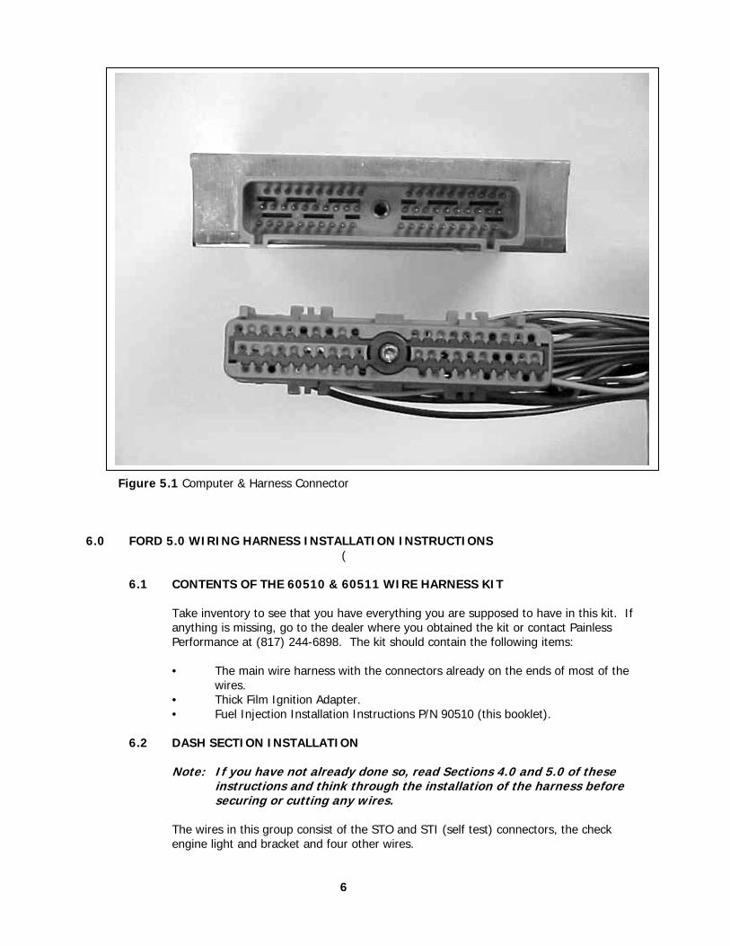
Figure 5.1 Computer & Harness Connector
6.0 FORD 5.0 WIRING HARNESS INSTALLATION INSTRUCTIONS
(
6.1 CONTENTS OF THE 60510 & 60511 WIRE HARNESS KIT
Take inventory to see that you have everything you are supposed to have in this kit. If anything is missing, go to the dealer where you obtained the kit or contact Painless Performance at (817) 244-6898. The kit should contain the following items:
• The main wire harness with the connectors already on the ends of most of the
wires. • Thick Film Ignition Adapter. • Fuel Injection Installation Instructions P/N 90510 (this booklet).
6.2 DASH SECTION INSTALLATION
Note: If you have not already done so, read Sections 4.0 and 5.0 of these
instructions and think through the installation of the harness before securing or cutting any wires.
The wires in this group consist of the STO and STI (self test) connectors, the check engine light and bracket and four other wires.
6
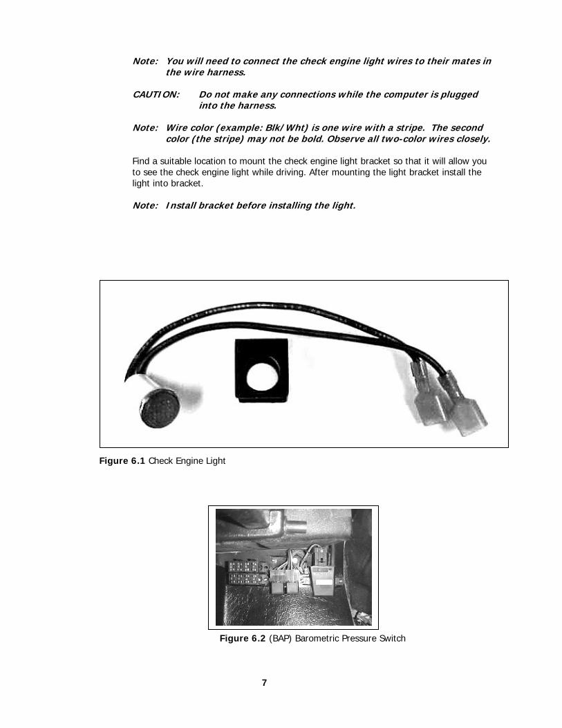
Note: You will need to connect the check engine light wires to their mates in
the wire harness.
CAUTION: Do not make any connections while the computer is plugged into the harness.
Note: Wire color (example: Blk/Wht) is one wire with a stripe. The second
color (the stripe) may not be bold. Observe all two-color wires closely.
Find a suitable location to mount the check engine light bracket so that it will allow you to see the check engine light while driving. After mounting the light bracket install the light into bracket.
Note: Install bracket before installing the light.
Figure 6.1 Check Engine Light Figure 6.2 (BAP) Barometric Pressure Switch
7
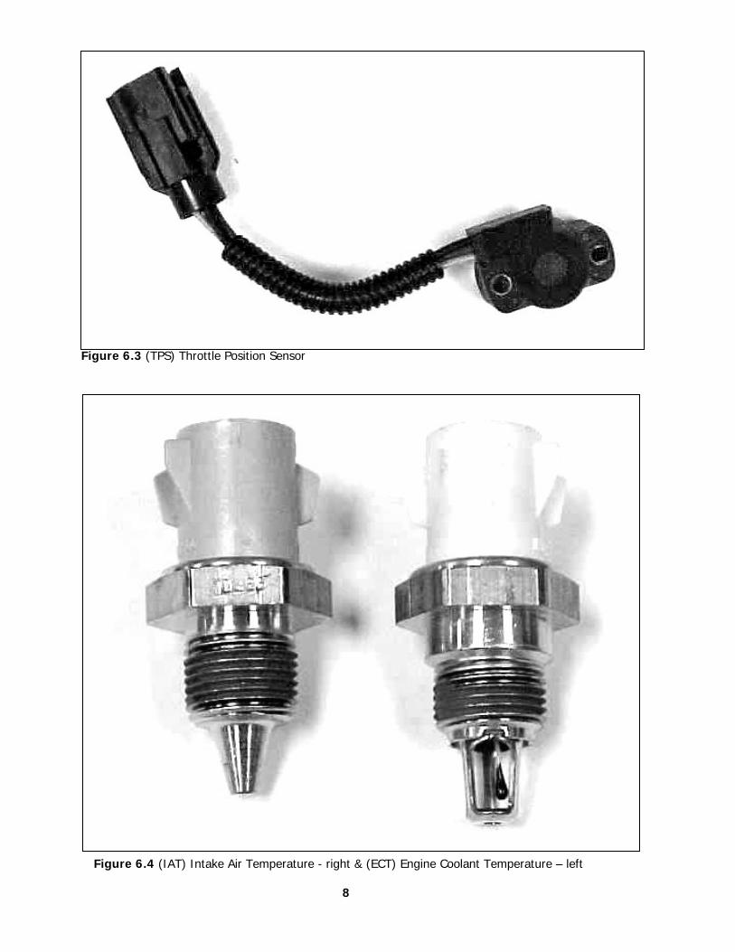
Figure 6.3 (TPS) Throttle Position Sensor
Figure 6.4 (IAT) Intake Air Temperature - right & (ECT) Engine Coolant Temperature – left
8
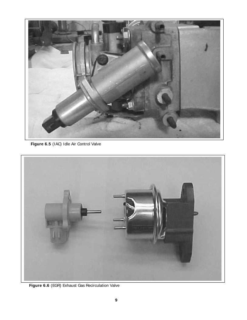
Figure 6.5 (IAC) Idle Air Control Valve
Figure 6.6 (EGR) Exhaust Gas Recirculation Valve
9
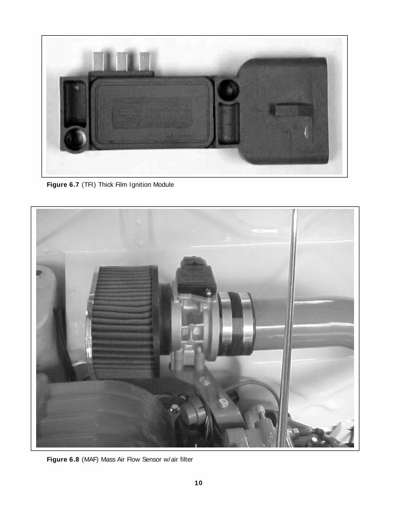
Figure 6.7 (TFI) Thick Film Ignition Module
Figure 6.8 (MAF) Mass Air Flow Sensor w/air filter
10
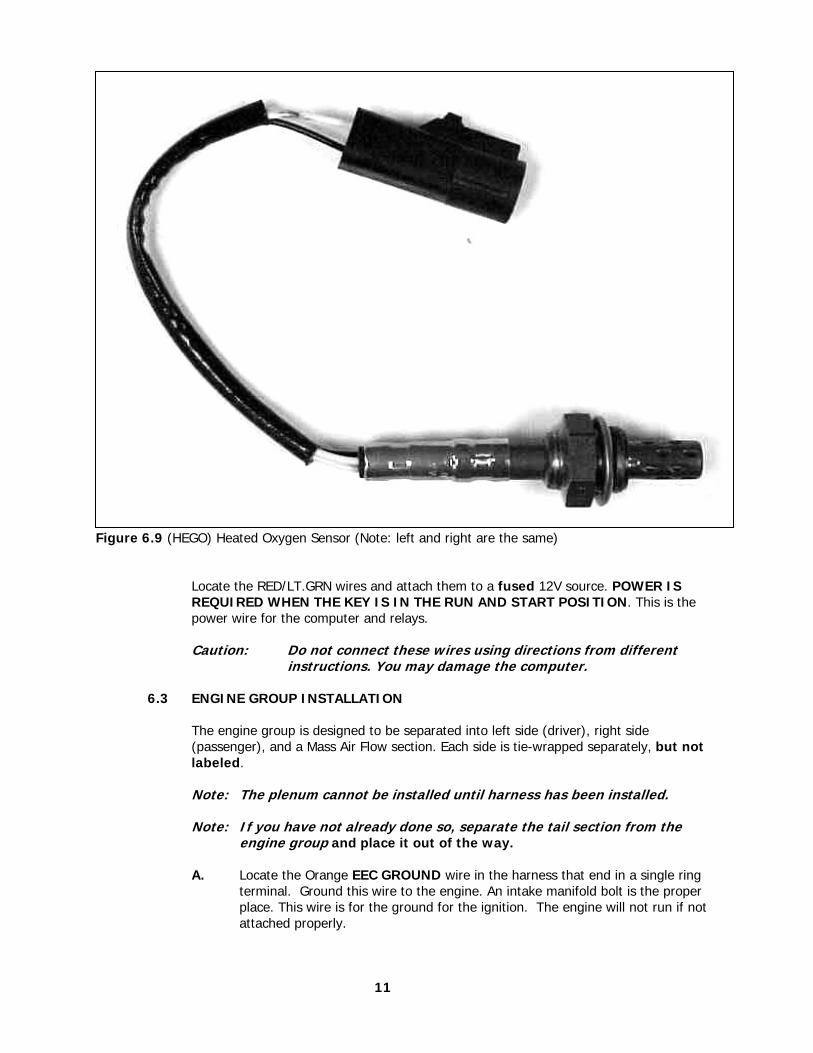
Figure 6.9 (HEGO) Heated Oxygen Sensor (Note: left and right are the same)
Locate the RED/LT.GRN wires and attach them to a fused 12V source. POWER IS REQUIRED WHEN THE KEY IS IN THE RUN AND START POSITION. This is the power wire for the computer and relays.
Caution: Do not connect these wires using directions from different
instructions. You may damage the computer.
6.3 ENGINE GROUP INSTALLATION
The engine group is designed to be separated into left side (driver), right side (passenger), and a Mass Air Flow section. Each side is tie-wrapped separately, but not labeled.
Note: The plenum cannot be installed until harness has been installed. Note: If you have not already done so, separate the tail section from the
engine group and place it out of the way.
A. Locate the Orange EEC GROUND wire in the harness that end in a single ring terminal. Ground this wire to the engine. An intake manifold bolt is the proper place. This wire is for the ground for the ignition. The engine will not run if not attached properly.
11
B. Starting at the rear of the engine, using Table 6.2, and the Figures in Section 6.3, begin attaching the connectors to their proper places and THEN secure the harness to the engine when ready.
C. Locate the yellow wire labeled STARTER RELAY and route it to the starter relay. Attach this wire to the BATTERY post on the relay.
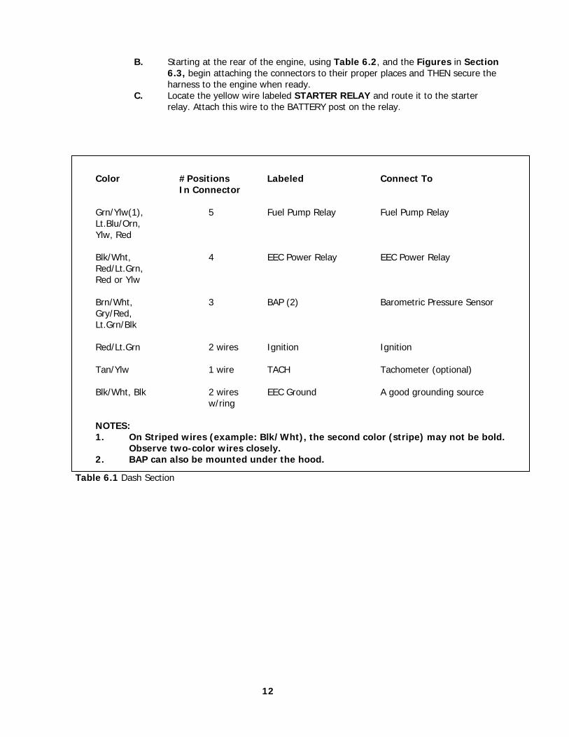
Table 6.1 Dash Section
12
Color #Positions Labeled Connect To In Connector Grn/Ylw(1), 5 Fuel Pump Relay Fuel Pump Relay Lt.Blu/Orn, Ylw, Red Blk/Wht, 4 EEC Power Relay EEC Power Relay Red/Lt.Grn, Red or Ylw Brn/Wht, 3 BAP (2) Barometric Pressure Sensor Gry/Red, Lt.Grn/Blk Red/Lt.Grn 2 wires Ignition Ignition Tan/Ylw 1 wire TACH Tachometer (optional) Blk/Wht, Blk 2 wires EEC Ground A good grounding source w/ring NOTES:
1. On Striped wires (example: Blk/Wht), the second color (stripe) may not be bold. Observe two-color wires closely.
2. BAP can also be mounted under the hood.
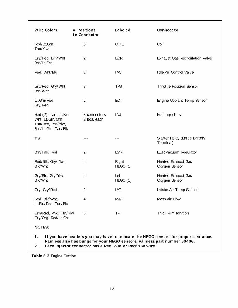
Table 6.2 Engine Section
13
Wire Colors # Positions Labeled Connect to In Connector Red/Lt.Grn, 3 COIL Coil Tan/Ylw Gry/Red, Brn/Wht 2 EGR Exhaust Gas Recirculation Valve Brn/Lt.Grn Red, Wht/Blu 2 IAC Idle Air Control Valve Gry/Red, Gry/Wht 3 TPS Throttle Position Sensor Brn/Wht Lt.Grn/Red, 2 ECT Engine Coolant Temp Sensor Gry/Red Red (2), Tan, Lt.Blu, 8 connectors INJ Fuel Injectors Wht, Lt.Grn/Orn, 2 pos. each Tan/Red, Brn/Ylw, Brn/Lt.Grn, Tan/Blk Ylw --- --- Starter Relay (Large Battery Terminal) Brn/Pnk, Red 2 EVR EGR Vacuum Regulator Red/Blk, Gry/Ylw, 4 Right Heated Exhaust Gas Blk/Wht HEGO (1) Oxygen Sensor Gry/Blu, Gry/Ylw, 4 Left Heated Exhaust Gas Blk/Wht HEGO (1) Oxygen Sensor Gry, Gry/Red 2 IAT Intake Air Temp Sensor Red, Blk/Wht, 4 MAF Mass Air Flow Lt.Blu/Red, Tan/Blu Orn/Red, Pnk, Tan/Ylw 6 TFI Thick Film Ignition Gry/Org, Red/Lt.Grn NOTES:
1. If you have headers you may have to relocate the HEGO sensors for proper clearance. Painless also has bungs for your HEGO sensors, Painless part number 60406.
2. Each injector connector has a Red/Wht or Red/Ylw wire.
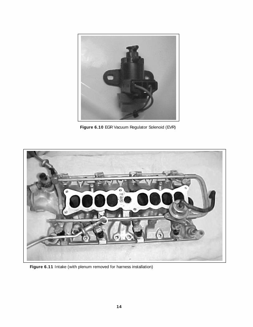
Figure 6.10 EGR Vacuum Regulator Solenoid (EVR) Figure 6.11 Intake (with plenum removed for harness installation)
14
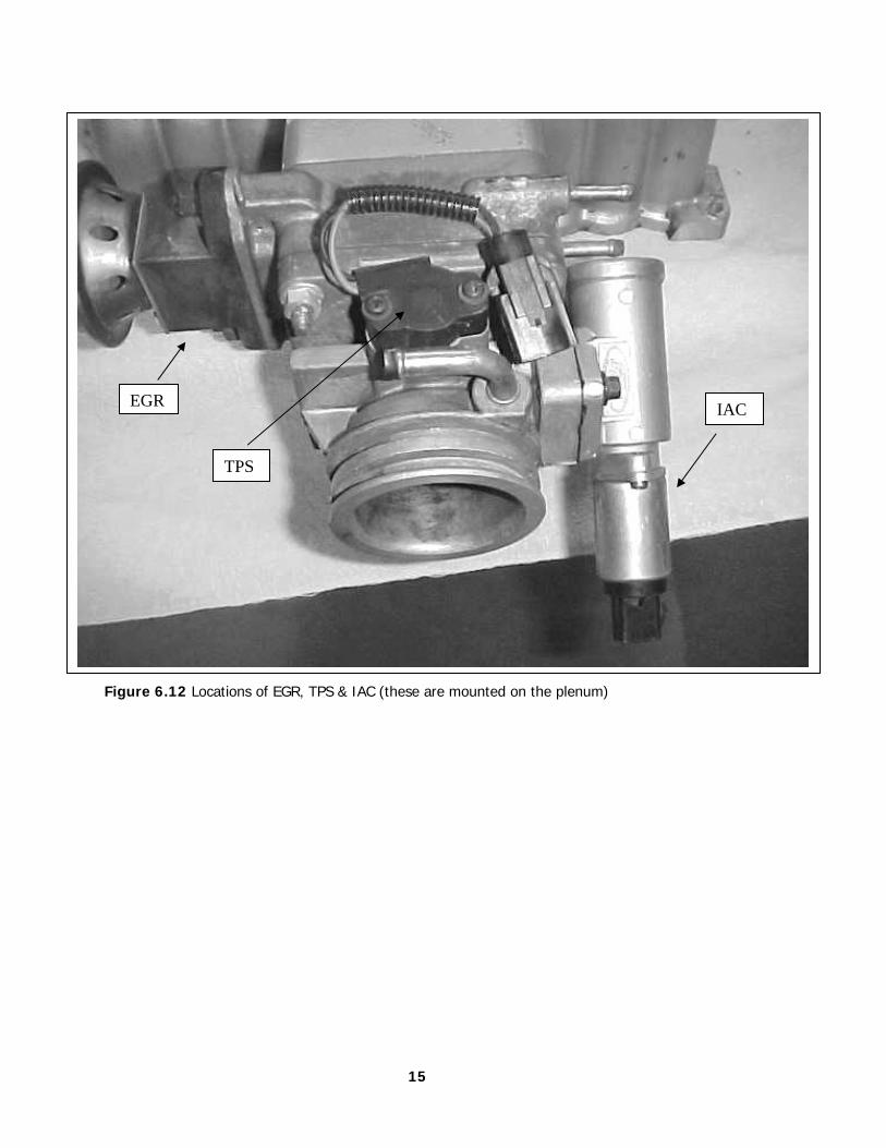
Figure 6.12 Locations of EGR, TPS & IAC (these are mounted on the plenum)
15
EGR
TPS
IAC
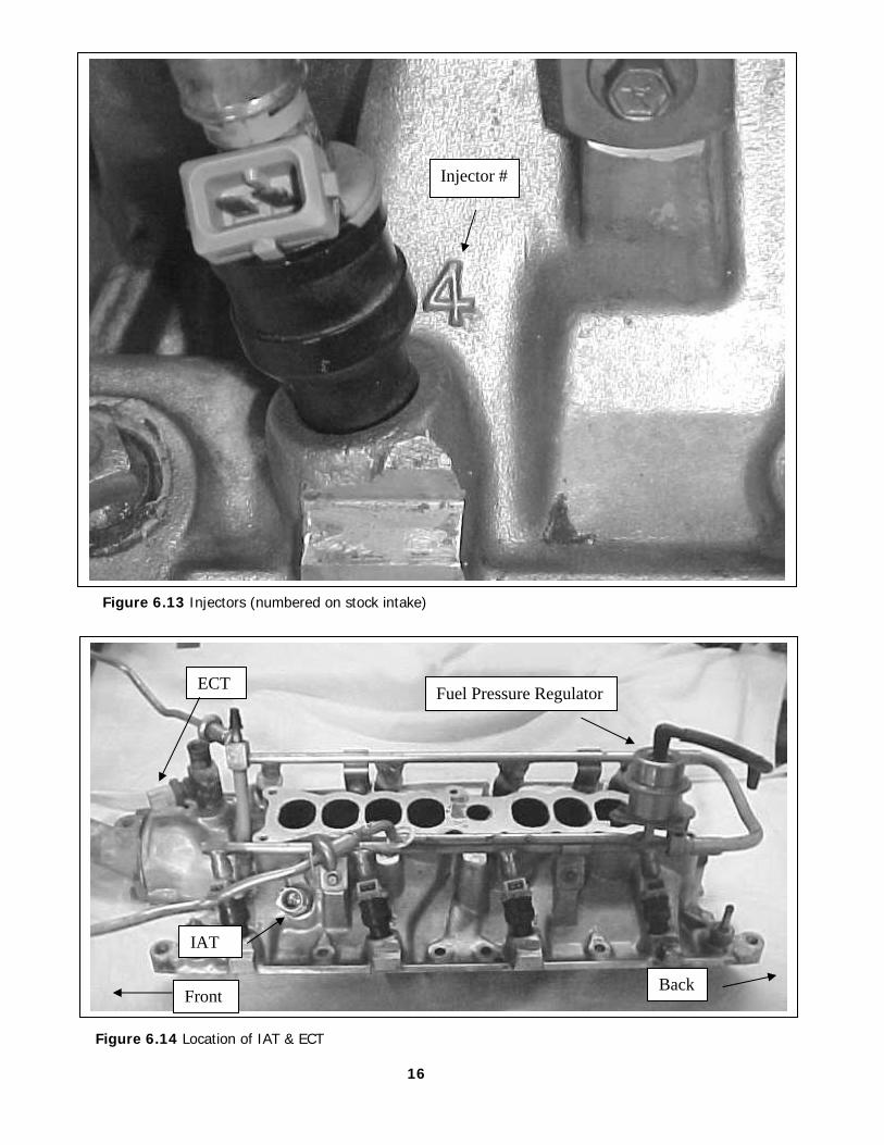
Figure 6.13 Injectors (numbered on stock intake)
Figure 6.14 Location of IAT & ECT
16
Injector #
Fuel Pressure Regulator ECT
IAT
Back Front
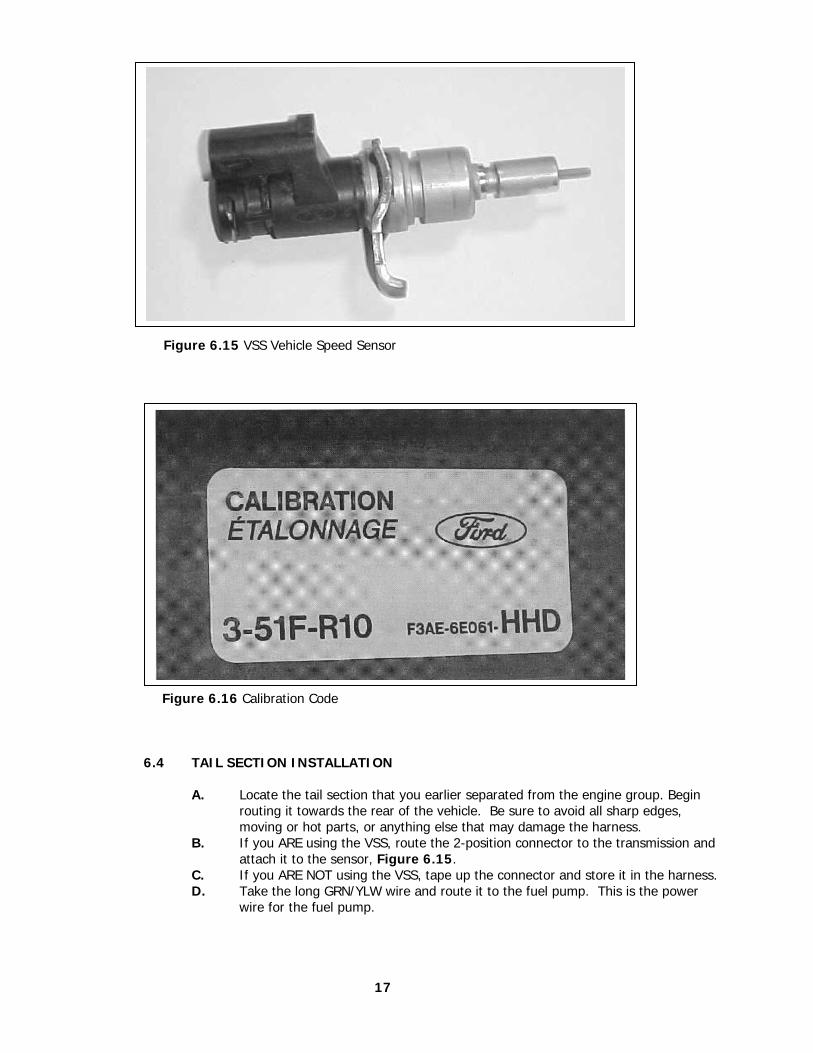
Figure 6.15 VSS Vehicle Speed Sensor Figure 6.16 Calibration Code 6.4 TAIL SECTION INSTALLATION
A. Locate the tail section that you earlier separated from the engine group. Begin routing it towards the rear of the vehicle. Be sure to avoid all sharp edges, moving or hot parts, or anything else that may damage the harness.
B. If you ARE using the VSS, route the 2-position connector to the transmission and attach it to the sensor, Figure 6.15.
C. If you ARE NOT using the VSS, tape up the connector and store it in the harness. D. Take the long GRN/YLW wire and route it to the fuel pump. This is the power
wire for the fuel pump.
17
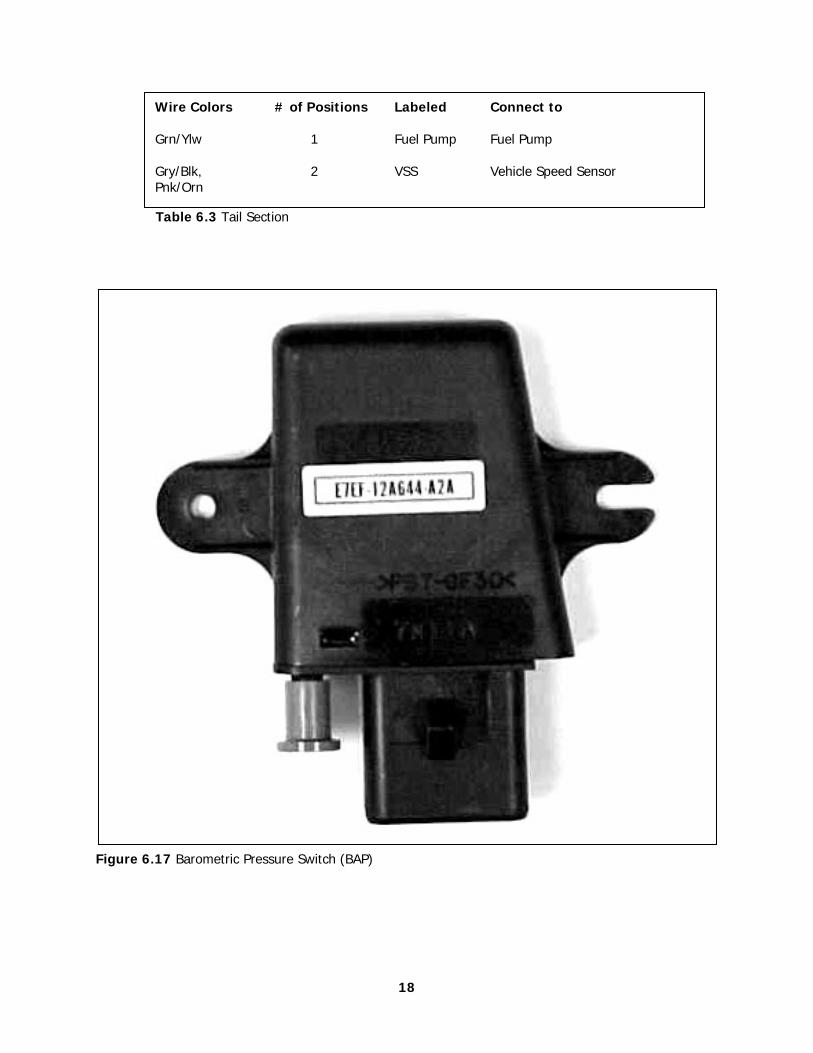
Table 6.3 Tail Section
Figure 6.17 Barometric Pressure Switch (BAP)
18
Wire Colors # of Positions Labeled Connect to Grn/Ylw 1 Fuel Pump Fuel Pump Gry/Blk, 2 VSS Vehicle Speed Sensor Pnk/Orn
7.0 FORD 5.0 START UP
7.1 Install the 60 position E.E.C connector into your E.E.C. your computer. Starting the bolt by hand. Once started use a 10mm socket to tighten it the rest of the way. DO NOT OVER TIGHTEN OR FORCE INTO PLACE.
7.2 The fuel system must be pressurized. This is done by turn the key on and off several times.
Note: Inspect your fuel lines for leaks. From the tank to the engine. 7.3 Start your engine and listen for noises that would indicate a problem. While listening inspect your engine for fluid leaks. 7.4 You are now ready to set your initial engine timing.
7.4.1 You must unplug the SPOUT connector located near the computer. 7.4.2 Loosen your distributor and set your initial timing to the factory setting
of 10º BTDC. 7.4.3 Tighten the distributor back down and check timing. Shut off engine. 7.4.4 Plug the SPOUT connector back together and restart the engine. The
timing should advance at this time. 7.5 Check your H.E.G.O bungs for leaks while your vehicle is still running.
8.0 TROUBLE SHOOTING INSTRUCTIONS
If you are having trouble with your engine running badly or not running at all, first perform basic trouble shooting (checking for faulty connections, spark, timing, fuel pressure, etc.) then see is The computer has stored a trouble code in its memory.
8.1 THE "CHECK ENGINE" LIGHT
Normally, the "check engine" light should come on when the ignition is initially turned on, then go out a few moments after the engine starts running. If it reappears, or stays on while the engine is running, the computer has detected a problem and a trouble code has been set.
8.1.1 The computer identifies particular trouble codes by flashing the "check engine"
light in a certain way. The codes are read by counting the flashes: A. The first digit (the "tens" digit) of the code is flashed quickly, followed by
a brief pause, then the second digit (or "ones" digit) is flashed, followed by a longer pause. For example, three (3) quick flashes followed by a brief pause followed by two (2) flashes indicates code 32.
B. The code will repeat itself three (3) times. The next code, if any, will be displayed in the same manner.
Note: When you access the codes from the computer a code 11 (one
flash followed by one flash) will first be displayed. THIS DOES NOT INDICATE A PROBLEM. Code 11 will be flashed 3 times, followed by the particular trouble codes, if any. If the computer merely flashes code 11 there are no trouble codes stored. Code 11 means the system passed.
19
8.2 RETRIEVING TROUBLE CODES FROM THE COMPUTER
KEY ON ENGINE OFF (KOEO)
8.2.1 Before you can perform this test you need to start your engine and allow it to run till you reach operating temperature. This is done so the H.E.G.O. sensors are warm.
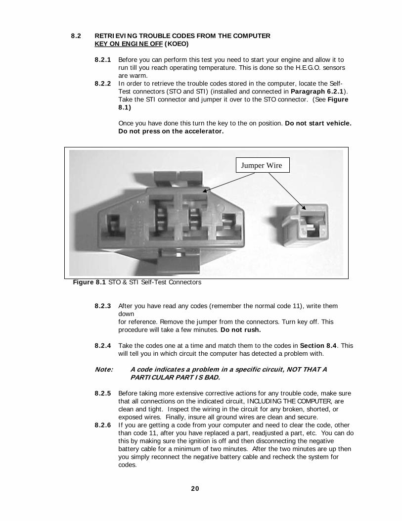
8.2.2 In order to retrieve the trouble codes stored in the computer, locate the Self- Test connectors (STO and STI) (installed and connected in Paragraph 6.2.1). Take the STI connector and jumper it over to the STO connector. (See Figure 8.1)
Once you have done this turn the key to the on position. Do not start vehicle. Do not press on the accelerator. Figure 8.1 STO & STI Self-Test Connectors
8.2.3 After you have read any codes (remember the normal code 11), write them down for reference. Remove the jumper from the connectors. Turn key off. This procedure will take a few minutes. Do not rush.
8.2.4 Take the codes one at a time and match them to the codes in Section 8.4. This
will tell you in which circuit the computer has detected a problem with.
Note: A code indicates a problem in a specific circuit, NOT THAT A PARTICULAR PART IS BAD.
8.2.5 Before taking more extensive corrective actions for any trouble code, make sure
that all connections on the indicated circuit, INCLUDING THE COMPUTER, are clean and tight. Inspect the wiring in the circuit for any broken, shorted, or
exposed wires. Finally, insure all ground wires are clean and secure. 8.2.6 If you are getting a code from your computer and need to clear the code, other
than code 11, after you have replaced a part, readjusted a part, etc. You can do this by making sure the ignition is off and then disconnecting the negative battery cable for a minimum of two minutes. After the two minutes are up then you simply reconnect the negative battery cable and recheck the system for codes.
20
Jumper Wire
8.3 ENGINE RUNNING (ER)
You will need to start and run your engine for several minutes, or until you have reached a normal operating temperature. As in KOEO test this is done to warm up the H.E.G.O sensors.
1. Turn off your engine and wait 10 to 15 seconds. 2. Jumper the STO and STI as described in the KOEO test. 3. Start your engine and read your codes. Match them to the codes in Section 8.4. 4. Once your finished Turn off your engine and remove the jumper.
8.4 EEC-IV Diagnostic Trouble Codes and Definitions
11 orc System pass 12 r Cannot control RPM during KOER Self-Test high rpm check
(KEY ON ENGINE RUNNING) 13 r Cannot control RPM during KOER Self-Test low rpm check 14 c PIP circuit failure (PROFILE IGNITION PICKUP) 15 o PCM Read Only Memory (ROM) test failed 15 c PCM Keep Alive Memory (KAM) test failed 16 r Rpm too low to perform HO2S test 18 r SPOUT circuit open 18 c IDM circuit failure/SPOUT circuit grounded 19 o Failure in PCM internal voltage 21 or ECT out of Self-Test range 22 orc MAP/BARO out of Self-Test range 23 or TPS out of Self-Test range 24 or IAT out of Self-test range 26 or MAF out of Self-Test range 29 c Insufficient input from Vehicle Speed Sensor (VSS) 31 orc EVP circuit below minimum voltage 32 orc EVP voltage below closed limit 33 rc EGR valve opening not detected 34 orc EVP voltage above closed limit 35 orc EVP circuit above maximum voltage 41 r HO2S circuit indicates system lean (Right HO2S) 41 c No HO2S switch detected (Right HO2S) 42 r HO2S circuit indicates system rich (Right HO2S) 51 oc ECT indicated –40ºC (-40ºF)/ circuit open 53 oc TPS circuit above maximum voltage 54 oc IAT indicated -40ºC (-40ºF)/circuit open 56 oc MAF circuit above maximum voltage 61 oc ECT indicated 123ºC (254ºF)/ circuit grounded 63 oc TPS circuit below minimum voltage 64 oc IAT indicated 123ºC (254º F)/ circuit grounded 66 c MAF circuit below minimum voltage 84 o EGR Vacuum Regulator (EVR) circuit failure 87 oc Fuel pump primary circuit failure 91 r HO2S circuit indicates system lean (Left HO2S) 91 c No HO2S switching detected (Left Ho2s) 92 r HO2S circuit indicates system rich (Left HO2S) 98 r Head fault is present-FMEM mode (Failure Mode Effects Management) No DTC’S Unable to initiate Self-Test or unable to output DTC’s
DTC’s not listed will not be applicable to this system
Key: o= Key On Engine Off, r = Engine Running, c = Continuous Memory
21
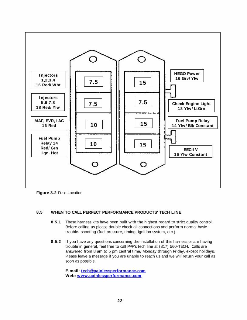
Figure 8.2 Fuse Location
8.5 WHEN TO CALL PERFECT PERFORMANCE PRODUCTS' TECH LINE
8.5.1 These harness kits have been built with the highest regard to strict quality control. Before calling us please double check all connections and perform normal basic trouble- shooting (fuel pressure, timing, ignition system, etc.).
8.5.2 If you have any questions concerning the installation of this harness or are having
trouble in general, feel free to call PPP's tech line at (817) 560-TECH. Calls are answered from 8 am to 5 pm central time, Monday through Friday, except holidays. Please leave a message if you are unable to reach us and we will return your call as soon as possible.
E-mail: [email protected] Web: www.painlessperformance.com
22
7.5
7.5
10
10
15
7.5
15
15
Injectors 1,2,3,4
16 Red/Wht
Injectors 5,6,7,8
18 Red/Ylw
MAF, EVR, IAC 16 Red
Fuel Pump Relay 14 Red/Grn Ign. Hot
HEGO Power 16 Gry/Ylw
Check Engine Light 18 Ylw/LtGrn
Fuel Pump Relay 14 Ylw/Blk Constant
EEC-IV 16 Ylw Constant

NOTES
23

Painless Performance Limited Warranty and Return Policy
Chassis harnesses and fuel injection harnesses are covered under a lifetime warranty. All other products manufactured and/or sold by Painless Performance are warranted to the original purchaser to be free from defects in material and workmanship under normal use. Painless Performance will repair or replace defective products without charge during the first 12 months from the purchase date. No products will be considered for warranty without a copy of the purchase receipt showing the sellers name, address and date of purchase. You must return the product to the dealer you purchased it from to initiate warranty procedures.
24