Embed Size (px)
Citation preview

Wire Harness Installation Instructions
For Installing: Part # 60101 - GM 87 & Later TBI Standard Harness
Part #60102 - GM 86-89 TPI Mass Air Flow (MAF) Standard Harness Part #60103 - GM 90-92 TPI w/Speed Density (MAP) Standard Harness
Part #60201 - GM 87 & Later TBI Extra Length Harness Part #60202 - GM 86-89 TPI Mass Air Flow (MAF) Extra Length Harness
Part #60203 - GM 90-92 TPI w/Speed Density (MAP) Extra Length Harness
Manual # 90503
Perfect Performance Products, LLC Painless Performance Products Division
9505 Santa Paula Drive, Fort Worth, Texas 76116 (800) 423-9696

We have attempted to provide you with as accurate instructions as possible, and are always concerned about corrections or improvements that can be made. If you have found any errors or omissions, or if you simply have comments or suggestions concerning these instructions, please write us at the address on the cover and let us know about them. Or, better yet, send us a fax at (817) 244-4024. We sincerely appreciate your business. For Technical Questions
E-mail Address: [email protected] Tech Line: 817-560-TECH
Perfect Performance Products, Inc. shall in no event be liable in contract or tort (including negligence) for special, indirect, incidental or consequential damages, such as, but not limited to, loss of property damage, or any other damages, costs or expenses which might be claimed as the result of the use or failure of the goods sold hereby, except only the cost of repair or replacement.
P/N 90503 Painless Wiring Manual November 2001 Revision #7
Copyright © 1996 by Perfect Performance Products, Inc.

TABLE OF CONTENTS
List of Figures.…………………………………………………………………… ii List of Tables.……………………………………………………………………. ii
List of Diagrams………………………………………………………………….. ii 1.0 Introduction.............................................................................................................. 1 2.0 About These Instructions......................................................................................... 1 3.0 Tools Needed............................................................................................................ 2 4.0 Pre-Installation and Harness Routing Guidelines.................................................…. 2
4.1 Transmission Lockup Function.................................................................… 2 4.2 Understand the Engine that you are using................................................…. 4
5.0 General Installation Instructions............................................................................... 8
5.1 Grounding The Vehicle................................................................................. 10 5.2 Rough Installation......................................................................................... 10 5.3 Harness Attachment...................................................................................... 10 5.4 Terminal Installation Instructions.............................................................… 11
5.5 Pre-adjustments before starting engine......................................................... 11 6.0 GM Throttle Body System Wire Harness Installation..........................................… 12 6.1 Contents of the 60101 Wire Harness Kits.................................................... 12
6.2 Specific Circuit Connections........................................................................ 13 6.2.1 Dash Section Installation.................................................................. 13
6.2.2 Sensor and Relay Board Group Installation..................................... 15 6.2.3 Throttle Body Injection Engine Group............................................. 17 6.2.4 Tail Section Installation.................................................................... 19
6.2.5 Add on TBI Emissions Kit............................................................... 22 7.0 Early-Version GM Tuned Port System Wire Harness Installation Instructions....... 24 7.1 Contents of the 60102 Wire Harness Kit...................................................... 24
7.2 Engine Group Installation............................................................................. 24 7.3 Dash Section Installation.............................................................................. 25 7.4 Sensor and Relay Installation........................................................................ 25 7.5 Tail Section Installation................................................................................ 25 7.6 Add on Early TPI Emissions Kit.................................................................. 29
8.0 Late-Version GM Tuned Port System Wire Harness Installation Instructions........ 32 8.1 Contents of the 60103 Wire Harness Kit..................................................... 32
8.2 Engine Group Installation............................................................................ 32 8.3 Dash Group Installation............................................................................... 32 8.4 Sensor and Relay Installation....................................................................... 32 8.5 Tail Section Installation......................................................................……. 32
i
9.0 Trouble Shooting Instructions.................................................................................. 33 9.1 The "Check Engine" Light............................................................................ 33
9.2 Retrieving Trouble Codes from the Computer........................................…. 33 9.3 When To Call Perfect Performance Products' Tech Line............................. 34 9.4 Add on Late TPI Emissions Kit........................................…....................... 35
LIST OF FIGURES Figure 4.1 Fuel Injection Computer................................................................... 5 Figure 4.2 External Coil Distributor Hookup.................................................... 6 Figure 4.3 Fuel Pump Relay Connector............................................................. 7 Figure 6.1 Optional Mounting Bracket (Part #60301)....................................... 13 Figure 6.2 Optional Sensor & Relay Board (Part #60303)...........................…. 13 Figure 6.3 Assembly Line Diagnostic Link (ALDL) Connector...................…. 14 Figure 6.4 Neutral Safety Switch....................................................................... 16 Figure 6.5 Brake Switch..................................................................................... 18 Figure 6.6 Sensor Relay Board Options............................................................ 20 Figure 6.7 Throttle Body Injection Unit............................................................ 20 Figure 6.8 Oxygen Sensor.................................................................................. 21 Figure 6.9 Knock Sensor.................................................................................... 21 Figure 6.10 TCC Solenoid................................................................................... 22 Figure 7.1 Tuned Port Injection System, Right Side......................................... 27 Figure 7.2 Tuned Port Injection System, Left Side............................................ 27 Figure 7.3 Engine Detail, Right Side................................................................. 28 Figure 7.4 MAF Sensor..................................................................................... 28 Figure 7.5 Engine Compartment Overview....................................................... 29 LIST OF TABLES Table 4.1 Compatible Parts.............................................................................. 8 Table 6.1 Sensor and Relay Installation........................................................... 18 Table 6.2 Throttle Body Injection Engine Section........................................... 19 Table 7.1 GM Tuned Port Injection Engine Group Connections.................... 26 Table 9.1 Diagnostic Trouble Codes................................................................ 35
LIST OF DIAGRAMS
Diagram 1 TBI Emissions……………………………………………………. 40 Diagram 2 Early TPI Emissions……………………………………………… 41 Diagram 3 Late TPI Emissions………………………………………………. 42 Diagram 4 Brake Switch Connection………………………………………… 43
ii
1.0 INTRODUCTION You have purchased what we at Perfect Performance Products, Inc. believe to be the most up-to-date and easiest-to-install automotive fuel injection harness on the market. It is designed for easy installation, even if you have no electrical experience.
This harness is designed to be a complete wiring system for the fuel injection system on General Motors tuned port (5.0L and 5.7L) injection engines. This includes all wiring that is needed by the computer to run and control the fuel injection system. The Throttle Body Injection Harnesses (part numbers 60101 and 60201) will work on a 4.3 liter V6 to a 454 c.i. (7.4L) engine.
Usually, the Computer and Sensor Board Group can easily be mounted under the dash (60101, 60102, 60103) or under the drivers seat (60201, 60202, 60203). Most of the wiring in the harness has been pre-terminated to the proper connector and all wire is rated at 125C and has been GM color-coded.
These fuel system harnesses have been divided into three major groups: ENGINE GROUP Includes wiring for the fuel injectors, distributor,
sensors and tail section.
DASH GROUP Includes ignition feed wire, assembly line diagnostic link (ALDL) connector, check-engine light, gearshift position wiring and brake switch wire.
SENSOR BOARD GROUP May include wiring for the manifold absolute
pressure (MAP) sensor, mass airflow relays, fuel pump relay, computer power fuses, electronic spark control (ESC), and cooling fan relay wire. The ESC and MAP sensor wires are long enough to route out and mount the sensors in the engine compartment. NOTE: Wiring used will vary by application.
2.0 ABOUT THESE INSTRUCTIONS
These instructions provide information for the installation of the 60101 and 60201 Throttle Body Injection Wire Harness Kit, the 60102 and 60202 Tuned Port Injection Wire Harness Kit (for MAF TPI's), and the 60103 and 60203 Tuned Port Injection Wire Harness Kit (for MAP TPI's). The contents of these instructions are divided into major Sections, as follows:
1.0 Introduction 2.0 About These Instructions 3.0 Tools Needed 4.0 Pre-Installation and Harness Routing Guidelines 5.0 General Installation Instructions 6.0 60101 and 60201 Throttle Body Harness Kit 7.0 60102 and 60202 Tuned Port Injection Harness Kit (early version) 8.0 60103 and 60203 Tuned Port Injection Harness Kit (late version) 9.0 Trouble Shooting Instructions and Trouble Codes
1

Sections are further divided into Paragraphs and Steps. Throughout, the Figure numbers refer to illustrations and the Table numbers refer to information in table form. These are located in or near the sections or paragraphs to which they correspond. Always pay careful attention to any Notes or any text labeled CAUTION.
3.0 TOOLS NEEDED
In addition to your regular tools, you will need, at least, the following:
Crimping Tool Note: Use a quality tool to avoid over-crimping. Wire Stripper Continuity Tester Caution: Do not use a test light to test the computer or
sensor wiring or you will damage the computer. Electric Drill 1-5/8" Hole saw (for the rubber grommet in the firewall)
4.0 PRE-INSTALLATION AND HARNESS ROUTING GUIDELINES
The installation of your harness kit consists mainly of two parts:
• The physical routing, positioning, and securing of the harness, wire groups, and individual wires and connectors.
• The proper electrical connection of the individual circuits.
These two major tasks are not separate steps, but are integrated together. That is, you will route some wires and make some connections, route some more wires and make some more connections.
We cannot tell you how to physically route the harness in your automobile. That depends a great deal upon the particular make of automobile and to what extent you want to secure and conceal the harness. We do offer some general guidelines and routing practices starting in Paragraph 4.3, GENERAL installation instructions in Section 5.0, and precise instructions concerning the electrical connections you will have to make beginning in Section 6.0. To help you begin thinking through the installation of your wire harness, read the following sections: 4.1 VEHICLE SPEED SENSOR AND TRANSMISSION LOCKUP
FUNCTIONS
Before you install the harness, please decide the following things: a. Are you going to use a 700 R4 Lockup Transmission that you want
the computer to control the lockup on? b. Does the engine have to be emissions legal; i.e. does the EGR
valve and /or air solenoid, and diverter valve need to be connected?
2
If you answered yes to either or both of these questions then you must connect the wires labeled VSS to a vehicle speed sensor that will provide a two (2) or four (4) pulse signal to the computer. On the Throttle Body and Early Model Tuned Port the sensor should output a square wave and on the late model tuned port engines it should provide a sine wave output. Painless Wiring offers the correct speed sensors for use with cable drive (mechanical) transmission outputs.
If you answered no to both of these questions then you may choose not to use a vehicle speed sensor, but the vehicle will operate more efficiently with one.
If you are going to use a vehicle speed sensor, take the orange/black and black/white wires in the dash section (labeled for the park/neutral indicator switch) and connect them to the Park/Neutral Indicator Switch, which is designed to tell the computer the transmission is in park, as instructed in 6.2.1, Step D and Figure 6.4. Do not connect the wires together.
Important: The orange/black and black/white wires in the dash section that
are labeled for the park/neutral indicator switch are to be connected to the park/neutral indicator switch, NOT A NEUTRAL SAFETY SWITCH. Under no circumstances should you connect these wires to a neutral safety switch. (A part/neutral indicator switch is a switch that tells the computer when the vehicle is in park or neutral, but a neutral safety switch is a switch that keeps the vehicle from starting unless it is in park or neutral.) You should never connect the orange/black and black/white wires to the vehicle speed sensor wiring.
If you are not going to use a vehicle speed sensor then you will take the orange/black and black/white wires in the dash section (labeled for the park/neutral indicator switch) and connect them together.
4.1.1 If you do NOT wish to use the lockup function, tape off and store the
single purple wire, marked brake switch, in the dash group and the 4-position square connector in the tail section.
4.1.2 If you ARE going to use the lockup circuit then you MUST have a vehicle speed sensor (VSS) and the correct brake switch. These are necessary to make the lockup function work correctly. The brake switch should be closed (electrically connected) when the brakes ARE NOT being applied and open (not electrically connected) when the brakes ARE being applied. This is the opposite of a standard brake light switch. The vehicle speed sensor lets the computer know how fast the wheels are turning.
4.1.3 Regardless of whether you use the lockup function, the vehicle speed sensor (VSS) must be used and is needed by the computer so that it can command the emissions control devices on the engine. This part is necessary if you want your vehicle to be street-legal.
3
4.1.4 There are two different VSS harness applications. All TBI and Early TPI
have a single brown wire that attaches to one of the two wires coming out of the 60115 speed sensor and the other wire is connected to ground. The Late TPI has two wires, purple and yellow that goes to and attaches to the 60116 sensor from the computer.
4.2 You should get to know the particular engine that you are using:
• GM THROTTLE BODY INJECTION (TBI) SYSTEM: The engine and the 60101 and 60201 harness are designed to use a manifold absolute pressure (MAP) sensor and an electronic spark control (ESC) module as well as the other wiring that the computer needs to operate.
• EARLY VERSION TUNED PORT INJECTION (TPI) SYSTEM WITH A MASS AIRFLOW (MAF) SENSOR: The 60102 and 60202 harness will support the mass airflow (MAF) sensor, the burn off circuit wiring, and the electronic spark control (ESC) module in addition to the other wiring common to the tuned port systems.
• LATE VERSION TUNED PORT INJECTION (TPI) SYSTEM WITHOUT A MASS AIRFLOW (MAF) SENSOR, DESIGNED TO USE A MANIFOLD ABSOLUTE PRESSURE (MAP) SENSOR, BUT DOES NOT REQUIRE AN ELECTRONIC SPARK CONTROL (ESC) MODULE: The 60103 and 60203 harnesses are designed for and will support this system. This system has three connectors at the computer instead of the two connectors shown in Figure 4.1.
Note: Computer chips, on the late model (90 and up) tuned port engines all factory chips have the vehicle anti-theft system (VATS) programmed into them so that they cannot be used unless the factory steering column, compatible with the computer, was installed. For the late model tuned port only you must obtain an aftermarket chip that does not have the VATS programming in it. The chip part numbers listed in the compatible parts chart are the chips that we offer for your convenience, but you do not have to use a Painless Wiring chip. For the late model tuned port systems, if you order a chip from someone other than Painless Wiring you will need to obtain a chip for a 1991 Camaro with the VATS system removed so that it will be compatible with our harness. Also, GM started using the VATS system in late 1989 so if you are using an 1989 chip on an early style tuned port motor then please be careful to use a chip that does not have the VATS programmed into it.
4
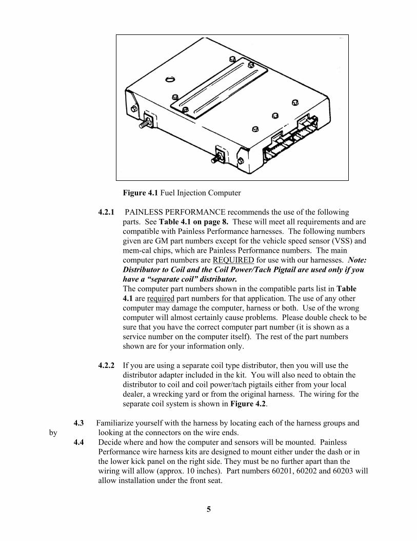
Figure 4.1 Fuel Injection Computer
4.2.1 PAINLESS PERFORMANCE recommends the use of the following parts. See Table 4.1 on page 8. These will meet all requirements and are compatible with Painless Performance harnesses. The following numbers given are GM part numbers except for the vehicle speed sensor (VSS) and mem-cal chips, which are Painless Performance numbers. The main computer part numbers are REQUIRED for use with our harnesses. Note: Distributor to Coil and the Coil Power/Tach Pigtail are used only if you have a “separate coil” distributor. The computer part numbers shown in the compatible parts list in Table 4.1 are required part numbers for that application. The use of any other computer may damage the computer, harness or both. Use of the wrong computer will almost certainly cause problems. Please double check to be sure that you have the correct computer part number (it is shown as a service number on the computer itself). The rest of the part numbers shown are for your information only.
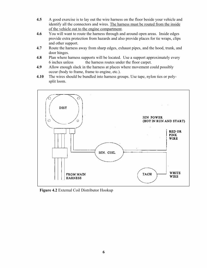
4.2.2 If you are using a separate coil type distributor, then you will use the
distributor adapter included in the kit. You will also need to obtain the distributor to coil and coil power/tach pigtails either from your local dealer, a wrecking yard or from the original harness. The wiring for the separate coil system is shown in Figure 4.2.
4.3 Familiarize yourself with the harness by locating each of the harness groups and
by looking at the connectors on the wire ends. 4.4 Decide where and how the computer and sensors will be mounted. Painless
Performance wire harness kits are designed to mount either under the dash or in the lower kick panel on the right side. They must be no further apart than the wiring will allow (approx. 10 inches). Part numbers 60201, 60202 and 60203 will allow installation under the front seat.
5
4.5 A good exercise is to lay out the wire harness on the floor beside your vehicle and
identify all the connectors and wires. The harness must be routed from the inside of the vehicle out to the engine compartment.
4.6 You will want to route the harness through and around open areas. Inside edges provide extra protection from hazards and also provide places for tie wraps, clips and other support.
4.7 Route the harness away from sharp edges, exhaust pipes, and the hood, trunk, and door hinges.
4.8 Plan where harness supports will be located. Use a support approximately every 6 inches unless the harness routes under the floor carpet.
4.9 Allow enough slack in the harness at places where movement could possibly occur (body to frame, frame to engine, etc.).
4.10 The wires should be bundled into harness groups. Use tape, nylon ties or poly-split loom.
Figure 4.2 External Coil Distributor Hookup
6
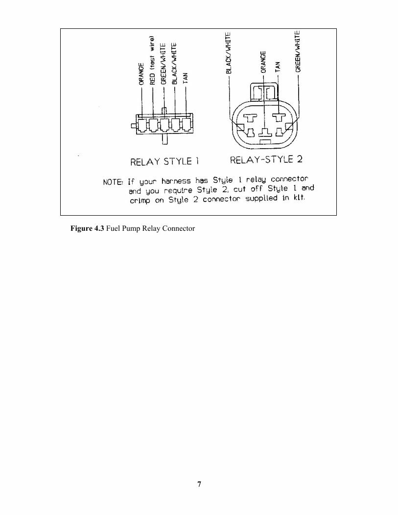
Figure 4.3 Fuel Pump Relay Connector
7
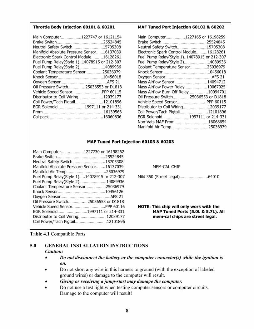
Table 4.1 Compatible Parts 5.0 GENERAL INSTALLATION INSTRUCTIONS
Caution: • Do not disconnect the battery or the computer connector(s) while the ignition is
on. • Do not short any wire in this harness to ground (with the exception of labeled
ground wires) or damage to the computer will result. • Giving or receiving a jump-start may damage the computer. • Do not use a test light when testing computer sensors or computer circuits.
Damage to the computer will result!
8
Throttle Body Injection 60101 & 60201 MAF Tuned Port Injection 60102 & 60202 Main Computer………………1227747 or 16121154 Main Computer……………..1227165 or 16198259 Brake Switch…………………………………..25524845 Brake Switch………………………………….25524845 Neutral Safety Switch………………………15705308 Neutral Safety Switch……………………..15705308 Manifold Absolute Pressure Sensor……16137039 Electronic Spark Control Module……….16128261 Electronic Spark Control Module……....16128261 Fuel Pump Relay(Style 1)..14078915 or 212-307 Fuel Pump Relay(Style 1)..14078915 or 212-307 Fuel Pump Relay(Style 2)…………………14089936 Fuel Pump Relay(Style 2)…………………14089936 Coolant Temperature Sensor……………25036979 Coolant Temperature Sensor……………25036979 Knock Sensor………………………………….10456018 Knock Sensor………………………………….10456018 Oxygen Sensor…………………………………..AFS 21 Oxygen Sensor…………………………………..AFS 21 Mass Airflow Sensor………………………..14094712 Oil Pressure Switch…………...25036553 or D1818 Mass Airflow Power Relay………………..10067925 Vehicle Speed Sensor……………………..PPP 60115 Mass Airflow Burn Off Relay……………..10094701 Distributor to Coil Wiring………………….12039177 Oil Pressure Switch……………25036553 or D1818 Coil Power/Tach Pigtail…………………….12101896 Vehicle Speed Sensor……………………..PPP 60115 EGR Solenoid……………………1997111 or 214-331 Distributor to Coil Wiring………………….12039177 Prom………………………………………………16139566 Coil Power/Tach Pigtail…………………….12101896 Cal-pack…………………………………….…..16060836 EGR Solenoid……………………1997111 or 214-331 Non-Vats MAF Prom…………………………16068654 Manifold Air Temp……………………………25036979
MAP Tuned Port Injection 60103 & 60203 Main Computer……..…………1227730 or 16198262 Brake Switch…………………………………….25524845 Neutral Safety Switch………………………..15705308 Manifold Absolute Pressure Sensor……..16137039 MEM-CAL CHIP Manifold Air Temp……………………………..25036979 Fuel Pump Relay(Style 1)…..14078915 or 212-307 Mild 350 (Street Legal)…………………….64010 Fuel Pump Relay(Style 2)……………………14089936 Coolant Temperature Sensor………………25036979 Knock Sensor……………………………………10456126 Oxygen Sensor………………….………………….AFS 21 Oil Pressure Switch…………..…25036553 or D1818 Vehicle Speed Sensor.……………………….PPP 60116 NOTE: This chip will only work with the EGR Solenoid……………..………1997111 or 214-331 MAP Tuned Ports (5.0L & 5.7L). All Distributor to Coil Wiring.……………………12039177 mem-cal chips are street legal. Coil Power/Tach Pigtail….……………………12101896
When routing the wires for the vehicle speed sensor (if used) make certain that they are at least 12 inches away from any ignition wiring (spark plug wires, etc.). Notes: • All of the adapters, listed in the manual, are included in the wiring kit. You
should use or remove them depending on your particular application. • If you are switching a TPI engine from MAF Sensor to MAP Sensor then you
must use the new Knock Sensor in Table 4.1. • An oil pressure SWITCH must be used with this harness. DO NOT BYPASS
OIL PRESSURE SWITCH WIRES. • If you are using an oil pressure switch that has two or three small pins surrounded
by a plastic collar for an electrical connection, an adapter is in the kit. • There is a normal, small current drain on these fuel injected systems. • Throttle body systems will NOT work with anything other than a STOCK
CAMSHAFT. • On throttle body systems, the power steering override switch, if so equipped, must
be wired IN-LINE on the A/C compressor power wire. • If you have a throttle body system and your throttle position sensor is different
from that shown in Figure 6.7, use the adapter in the kit. • Each connector in this harness is different and will not fit in the wrong place.
NEVER FORCE ANY CONNECTOR. • When connecting the plugs to the computer USE EXTREME CARE to make sure
none of the pins in the computer are or have become bent. • IF YOU HAVE A GM SEPARATE COIL IGNITION SYSTEM ON YOUR
ENGINE: use the adapter in the kit. • FOR YOUR DISTRIBUTOR: The power wire used on the previous distributor
should work fine as long as there is no ignition resistor in the circuit. It must be a power wire (14 ga. minimum) that is HOT (+12V) when the ignition switch is in the START AND RUN positions. Connect it to the terminal on the distributor cap labeled BAT or to the pink wire on the separate Coil Ignition System. This wire provides power to the ignition coil. YOUR AUTOMOBILE WILL NOT START OR RUN WITHOUT IT.
• The timing connector for the ignition is near the computer. • The fuel pump relay connector on the harness requires a style 1. A style 2 relay
may be substituted. See Figure 4.3 for illustration and Table 4.1 for part numbers.
• The fuel pump you are using MUST be rated at a minimum of 45 pounds PSI (per square inch) for tuned port systems or 15 pounds PSI for throttle body systems.
• If you have headers you may have to relocate the knock sensor for proper clearance. See Figure 6.9.
Note: The oil pressure switch wires are designed to be connected to an oil pressure switch, not the oil pressure sending unit. An oil pressure sending unit is for a gauge or an indicator light and will only have one terminal on the top. The stock oil pressure switch is cigar shaped and has three terminals. If you wish to use the stock oil pressure switch then you will use the oil pressure switch adapter included with this kit. On the oil pressure switch adapter there are two wires that match the wire colors coming from our harness and there is also an extra wire.
9
The extra wire is for the factory oil pressure gauge or indicator light, depending on what the switch was originally designed for. You may also obtain a smaller oil pressure switch if you have clearance problems with the original oil pressure switch. This type of switch has two male connectors that will plug directly into the harness.
5.1 GROUNDING THE VEHICLE
A perfectly and beautifully wired automobile will nevertheless have problems if everything is not properly grounded. Don't go to the effort of installing a quality wire harness only to neglect proper grounding.
5.1.1 Connect a ground strap or cable (minimum of a 4-gauge wire) from the
negative battery terminal to the automobile chassis (frame). 5.1.2 Connect a ground strap from the engine to the chassis (frame). DO NOT
RELY UPON THE MOTOR MOUNTS TO MAKE THIS CONNECTION.
5.1.3 Connect a ground strap from the engine to the body.
5.2 ROUGH INSTALLATION
Caution: Disconnect the power from your vehicle by removing the negative battery cable from the battery.
Note: Make no wire connections or permanent mounting of any kind at this
time.
5.2.1 Position the computer and sensors in their intended locations. 5.2.2 Drill a 1-5/8" hole for the firewall grommet near the computer for the
engine group and tail section to pass through. 5.2.3 Route the engine group and tail section through the hole. Push the
grommet (already installed on the harness) into the hole until it is seated. 5.2.4 Route the dash group over to the driver's side of the car. 5.2.5 Route the sensor group to the area where the sensors will be mounted.
5.3 HARNESS ATTACHMENT
Note: Harness routing and shaping will be a time-consuming task. Taking
your time will enhance the beauty of your installation. Please be patient and take your time.
5.3.1 Permanently mount computer. You should mount the parts (sensors,
relays, etc.) that will be used for your engine at this time. These parts will vary by application.
5.3.2 Mold harness groups to the contour of the dash, engine, frame, etc. Remember to route the harness away from sharp edges, exhaust pipes, hinges, and moving parts.
5.3.3 Attach harness groups to your automobile with clips or ties starting at the computer and working your way outward.
10
Note: Do not tighten tie wraps or mounting devices at this time. Make all harness attachments LOOSELY.
5.3.4 When used every 1-1/2" or so on the visible areas of the harness, plastic
wire ties make a very attractive assembly. Otherwise, a tie installed in other areas every 6" or so will hold the wires in place securely. REMEMBER TO TAKE YOUR TIME.
5.4 TERMINAL INSTALLATION INSTRUCTIONS
Note: In the following steps you will be making the circuit connections.
Before you start, you should carefully read Sections 6.0 through 8.0, as applicable, and continually refer to the wire connection charts, DOUBLE CHECKING your length calculations before cutting any wire or making any connections. These directions are for the wires which do not have a connector already installed on them.
5.4.1 Have all needed tools and connectors handy. 5.4.2 Select the correct terminal for the wire and application. 5.4.3 Determine the correct wire length and cut the wire. Remember to allow
enough slack in the harness and wires at places where movement could possibly occur. DOUBLE-CHECK YOUR CALCULATIONS.
5.4.4 Strip insulation away from wire. Strip only enough length necessary for the type of terminal you are using.
Note: In the following step, make sure that the terminal is crimped with the
proper die in the crimping tool. An improper crimp will not make a good connection. DO NOT OVER CRIMP.
5.4.5 Crimp the terminal onto the wire. 5.4.6 Connecting the wires and connectors throughout the harness is a repeating
process. Make sure that each wire is first properly routed and then attach. DO NOT ATTACH THEN ROUTE AFTERWARD.
5.4.7 When all wires are attached, tighten the mounts and ties to secure harness permanently.
5.4.8 Attach the connectors to the computer BEING CAREFUL NOT TO BEND ANY PINS.
5.4.9 Only after all connections have been made throughout the harness, connect the battery to the vehicle.
Caution: Be sure the ignition is off when you reconnect the battery or you
will damage the computer.
5.5 PRE-ADJUSTMENTS BEFORE STARTING ENGINE 5.5.1 Throttle Position Sensor Adjustment (TPI ONLY)
11
A. Turn on ignition but do not start engine. B. Check to insure throttle is not depressed C. At the throttle position sensor, place a digital voltmeter's probes
into the blue and black wires in the back of the sensors connector, which is plugged into the sensor.
D. Loosen the sensor mounting screws and adjust the sensor until the meter reads .5 volts (1/2 of one volt).
E. Tighten the mounting screws and recheck the meter reading. F. Some after market chips require a different setting, check their
instructions carefully 5.5.2 Base Engine Idle Adjustment (all TBI & TPI) A. Turn on ignition but do not start engine. B. Jumper A & B of the ALDL as if you were checking codes. C. Wait 30 seconds and then remove the plug from the IAC motor.
D. Remove jumper from ALDL. E. Start engine and adjust idle speed with adjusting screw at throttle lever
(there may be a cap covering the adjusting screw that will need to be removed and discarded).
F. Shut off engine and disconnect battery for one minute. G. Plug the IAC connector back in and then reconnect the battery. H. Start engine and check for proper idle speed. 6.0 GM THROTTLE BODY SYSTEM WIRE HARNESS INSTALLATION
INSTRUCTIONS (The Painless Performance harness and systems are designed around the 1990 Chevy Pickup)
6.1 Contents of the 60101 and 60201 Wire Harness Kit
Take inventory to see that you have everything you are supposed to have in this kit. If anything is missing, go to the dealer where you obtained the kit or contact Painless Performance at (800) 423-9696. The kit should contain the following items: • The main wire harness with the connectors already on the ends of most of
the wires. • Distributor, Oil Pressure and Throttle Position Adapters. • Fuel Injection Installation Instructions P/N 90503 (this booklet). The following optional parts are not included in the kit but are available from Painless Performance: • Computer Mounting Bracket, P/N 60301. See Figure 6.1. • Sensor and Relay Board, P/N 60303. It is shown with part attached in
Figure 6.2. (Parts Not Included) • Emission Control Device Harnesses (Part # 60310 and 60311).
12
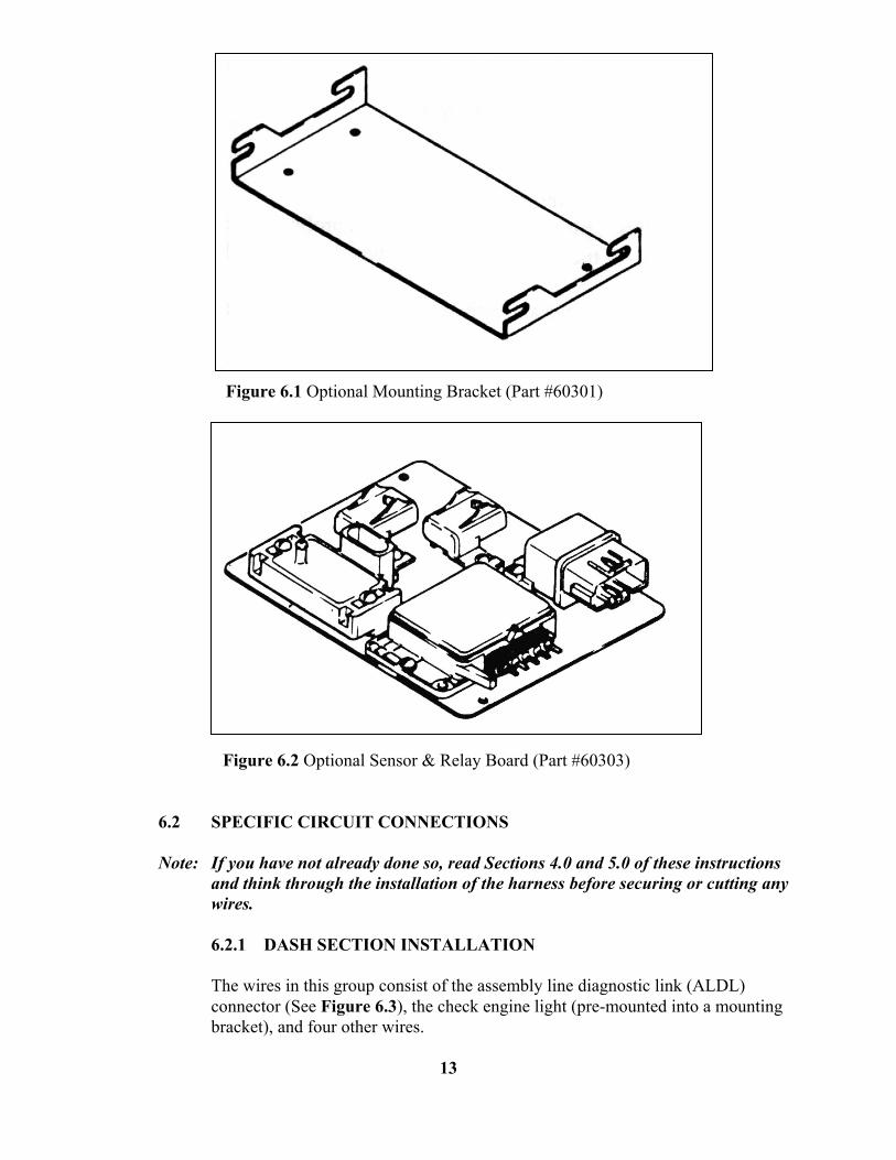
Figure 6.1 Optional Mounting Bracket (Part #60301) Figure 6.2 Optional Sensor & Relay Board (Part #60303) 6.2 SPECIFIC CIRCUIT CONNECTIONS
Note: If you have not already done so, read Sections 4.0 and 5.0 of these instructions and think through the installation of the harness before securing or cutting any wires.
6.2.1 DASH SECTION INSTALLATION
The wires in this group consist of the assembly line diagnostic link (ALDL) connector (See Figure 6.3), the check engine light (pre-mounted into a mounting bracket), and four other wires.
13
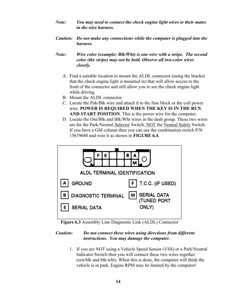
Note: You may need to connect the check engine light wires to their mates
in the wire harness.
Caution: Do not make any connections while the computer is plugged into the harness. Note: Wire color (example: Blk/Wht) is one wire with a stripe. The second
color (the stripe) may not be bold. Observe all two-color wires closely.
A. Find a suitable location to mount the ALDL connector (using the bracket
that the check engine light is mounted in) that will allow access to the front of the connector and still allow you to see the check engine light while driving.
B. Mount the ALDL connector. C. Locate the Pnk/Blk wire and attach it to the fuse block or the coil power
wire. POWER IS REQUIRED WHEN THE KEY IS IN THE RUN AND START POSITION. This is the power wire for the computer.
D. Locate the Orn/Blk and Blk/Wht wires in the dash group. These two wires are for the Park/Neutral Selector Switch, NOT the Neutral Safety Switch. If you have a GM column then you can use the combination switch P/N 15679680 and wire it as shown in FIGURE 6.4.
Figure 6.3 Assembly Line Diagnostic Link (ALDL) Connector
Caution: Do not connect these wires using directions from different instructions. You may damage the computer.
1. If you are NOT using a Vehicle Speed Sensor (VSS) or a Park/Neutral
Indicator Switch then you will connect these two wires together (orn/blk and blk/wht). When this is done, the computer will think the vehicle is in park. Engine RPM may be limited by the computer!
14
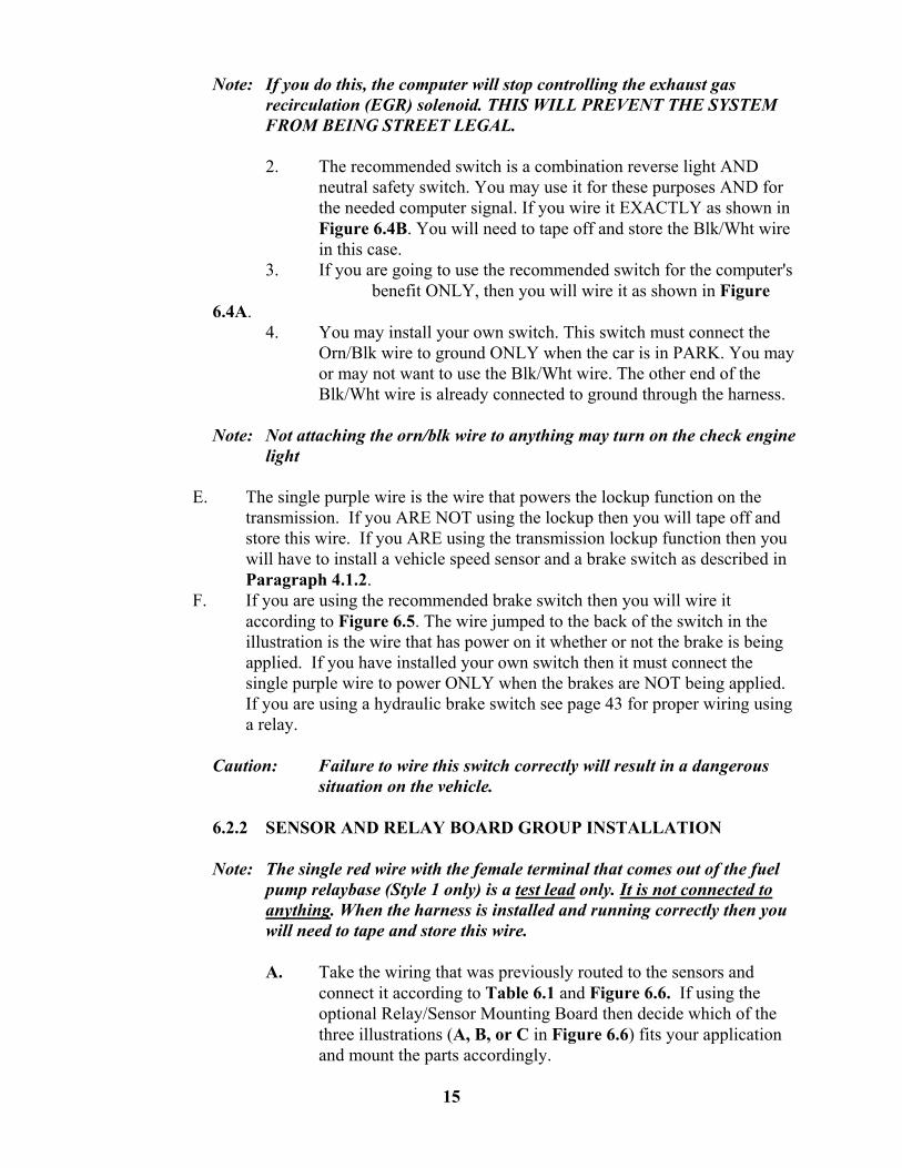
Note: If you do this, the computer will stop controlling the exhaust gas
recirculation (EGR) solenoid. THIS WILL PREVENT THE SYSTEM FROM BEING STREET LEGAL.
2. The recommended switch is a combination reverse light AND
neutral safety switch. You may use it for these purposes AND for the needed computer signal. If you wire it EXACTLY as shown in Figure 6.4B. You will need to tape off and store the Blk/Wht wire in this case.
3. If you are going to use the recommended switch for the computer's benefit ONLY, then you will wire it as shown in Figure 6.4A.
4. You may install your own switch. This switch must connect the Orn/Blk wire to ground ONLY when the car is in PARK. You may or may not want to use the Blk/Wht wire. The other end of the Blk/Wht wire is already connected to ground through the harness.
Note: Not attaching the orn/blk wire to anything may turn on the check engine
light
E. The single purple wire is the wire that powers the lockup function on the transmission. If you ARE NOT using the lockup then you will tape off and store this wire. If you ARE using the transmission lockup function then you will have to install a vehicle speed sensor and a brake switch as described in Paragraph 4.1.2.
F. If you are using the recommended brake switch then you will wire it according to Figure 6.5. The wire jumped to the back of the switch in the illustration is the wire that has power on it whether or not the brake is being applied. If you have installed your own switch then it must connect the single purple wire to power ONLY when the brakes are NOT being applied. If you are using a hydraulic brake switch see page 43 for proper wiring using a relay.
Caution: Failure to wire this switch correctly will result in a dangerous
situation on the vehicle. 6.2.2 SENSOR AND RELAY BOARD GROUP INSTALLATION
Note: The single red wire with the female terminal that comes out of the fuel pump relaybase (Style 1 only) is a test lead only. It is not connected to anything. When the harness is installed and running correctly then you will need to tape and store this wire.
A. Take the wiring that was previously routed to the sensors and
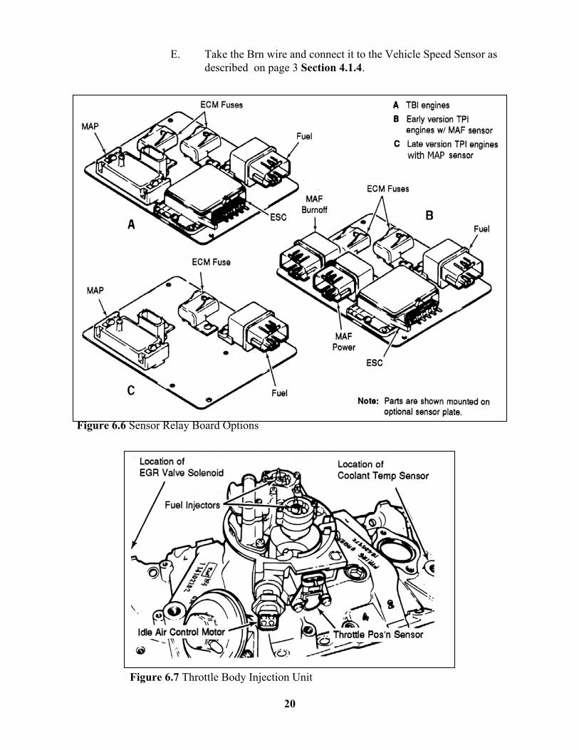
connect it according to Table 6.1 and Figure 6.6. If using the optional Relay/Sensor Mounting Board then decide which of the three illustrations (A, B, or C in Figure 6.6) fits your application and mount the parts accordingly.
15
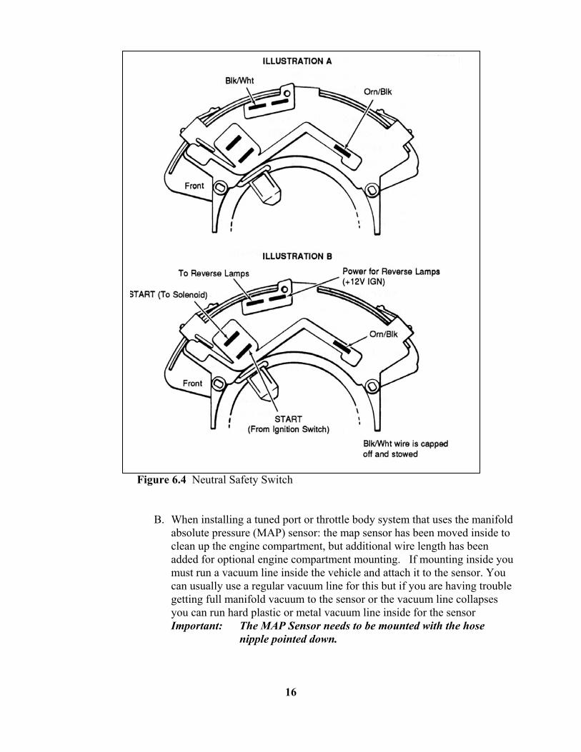
Figure 6.4 Neutral Safety Switch
B. When installing a tuned port or throttle body system that uses the manifold absolute pressure (MAP) sensor: the map sensor has been moved inside to clean up the engine compartment, but additional wire length has been added for optional engine compartment mounting. If mounting inside you must run a vacuum line inside the vehicle and attach it to the sensor. You can usually use a regular vacuum line for this but if you are having trouble getting full manifold vacuum to the sensor or the vacuum line collapses you can run hard plastic or metal vacuum line inside for the sensor Important: The MAP Sensor needs to be mounted with the hose
nipple pointed down.
16

6.2.3 THROTTLE BODY INJECTION ENGINE GROUP
Note: If you have not already done so, separate the tail section from the engine group and place it out of the way.
A. Locate the two Blk/Wht wires in the harness that end in a single
ring terminal. Ground these wires to the engine. An intake manifold bolt is a good choice. These wires are the ground for the harness. The engine will not work if not attached properly.
B. Starting at the rear of the engine, using Figure 6.7, Table 6.2, and the specific illustrations indicated in Table 6.2, begin attaching the connectors to their proper places and THEN secure the harness to the engine when ready.
C. If you wish to use the power steering override switch (wire not furnished in kit) it must be wired IN-LINE along with the green/white wire marked a/c power in the harness with the power wire for the A/C compressor.
Note: If the throttle position sensor on your throttle body is different from the one illustrated in Figure 6.7, an adapter is in the kit.
Note: in order to set base timing on these harnesses you will have to disconnect the timing connector located inside the vehicle. This is like disconnecting a vacuum hose on an old style distributor. It is approximately 6 inches from the main computer connectors. The timing connector is in line on the tan wire with the black stripe (Tan/Blk) and looks similar to the oxygen sensor connector. Once you have this disconnected you should set base timing as you normally would then re-connect the timing connector, clear the codes and test run the engine.
17
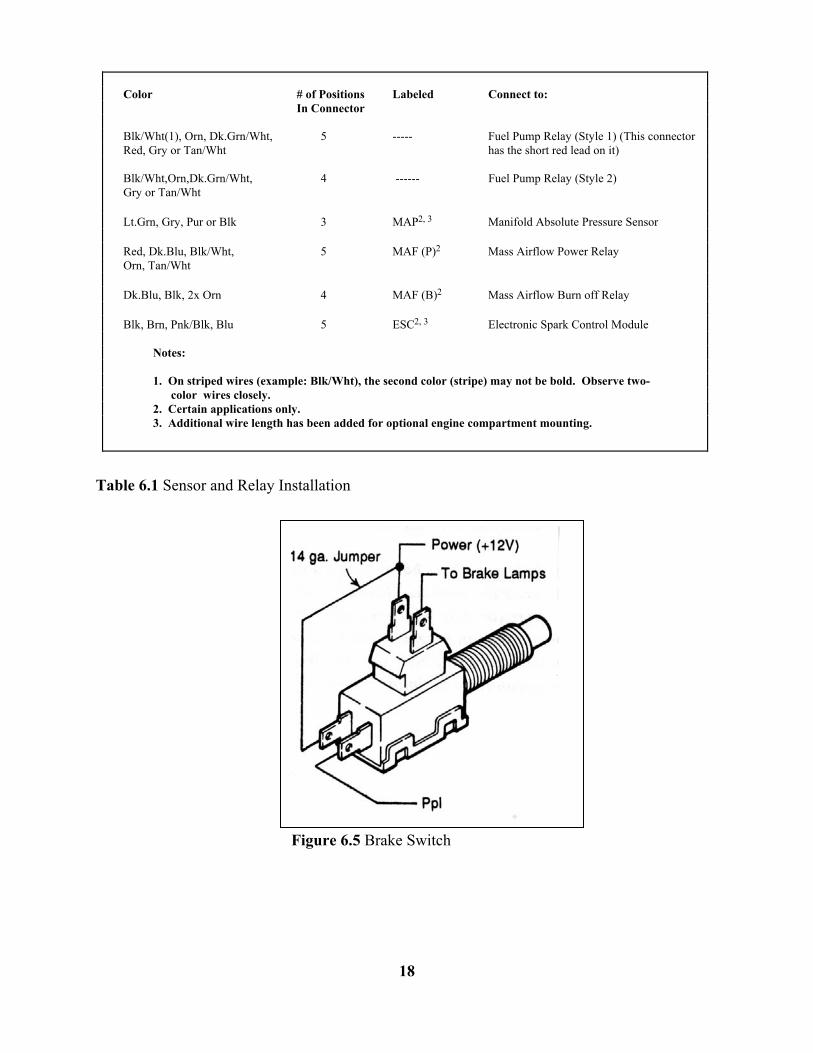
Table 6.1 Sensor and Relay Installation Figure 6.5 Brake Switch
18
Color # of Positions Labeled Connect to: In Connector Blk/Wht(1), Orn, Dk.Grn/Wht, 5 ----- Fuel Pump Relay (Style 1) (This connector Red, Gry or Tan/Wht has the short red lead on it) Blk/Wht,Orn,Dk.Grn/Wht, 4 ------ Fuel Pump Relay (Style 2) Gry or Tan/Wht Lt.Grn, Gry, Pur or Blk 3 MAP2, 3 Manifold Absolute Pressure Sensor Red, Dk.Blu, Blk/Wht, 5 MAF (P)2 Mass Airflow Power Relay Orn, Tan/Wht Dk.Blu, Blk, 2x Orn 4 MAF (B)2 Mass Airflow Burn off Relay Blk, Brn, Pnk/Blk, Blu 5 ESC2, 3 Electronic Spark Control Module
Notes: 1. On striped wires (example: Blk/Wht), the second color (stripe) may not be bold. Observe two- color wires closely. 2. Certain applications only.
3. Additional wire length has been added for optional engine compartment mounting.
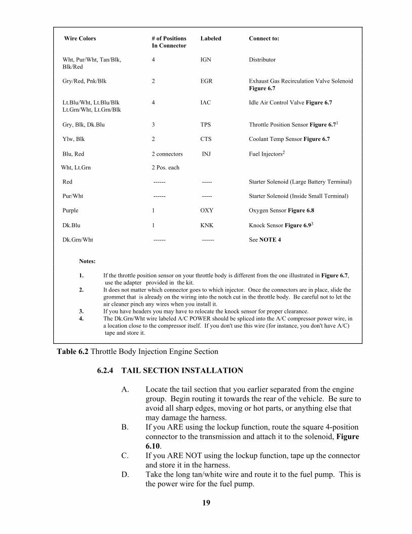
Table 6.2 Throttle Body Injection Engine Section 6.2.4 TAIL SECTION INSTALLATION
A. Locate the tail section that you earlier separated from the engine group. Begin routing it towards the rear of the vehicle. Be sure to avoid all sharp edges, moving or hot parts, or anything else that may damage the harness.
B. If you ARE using the lockup function, route the square 4-position connector to the transmission and attach it to the solenoid, Figure 6.10.
C. If you ARE NOT using the lockup function, tape up the connector and store it in the harness.
D. Take the long tan/white wire and route it to the fuel pump. This is the power wire for the fuel pump.
19
Wire Colors # of Positions Labeled Connect to: In Connector Wht, Pur/Wht, Tan/Blk, 4 IGN Distributor Blk/Red Gry/Red, Pnk/Blk 2 EGR Exhaust Gas Recirculation Valve Solenoid
Figure 6.7 Lt.Blu/Wht, Lt.Blu/Blk 4 IAC Idle Air Control Valve Figure 6.7 Lt.Grn/Wht, Lt.Grn/Blk Gry, Blk, Dk.Blu 3 TPS Throttle Position Sensor Figure 6.71 Ylw, Blk 2 CTS Coolant Temp Sensor Figure 6.7 Blu, Red 2 connectors INJ Fuel Injectors2 Wht, Lt.Grn 2 Pos. each Red ------ ----- Starter Solenoid (Large Battery Terminal) Pur/Wht ------ ----- Starter Solenoid (Inside Small Terminal) Purple 1 OXY Oxygen Sensor Figure 6.8 Dk.Blu 1 KNK Knock Sensor Figure 6.93 Dk.Grn/Wht ------ ------ See NOTE 4
Notes:
1. If the throttle position sensor on your throttle body is different from the one illustrated in Figure 6.7, use the adapter provided in the kit. 2. It does not matter which connector goes to which injector. Once the connectors are in place, slide the grommet that is already on the wiring into the notch cut in the throttle body. Be careful not to let the air cleaner pinch any wires when you install it. 3. If you have headers you may have to relocate the knock sensor for proper clearance. 4. The Dk.Grn/Wht wire labeled A/C POWER should be spliced into the A/C compressor power wire, in a location close to the compressor itself. If you don't use this wire (for instance, you don't have A/C) tape and store it.
E. Take the Brn wire and connect it to the Vehicle Speed Sensor as
described on page 3 Section 4.1.4. Figure 6.6 Sensor Relay Board Options Figure 6.7 Throttle Body Injection Unit
20
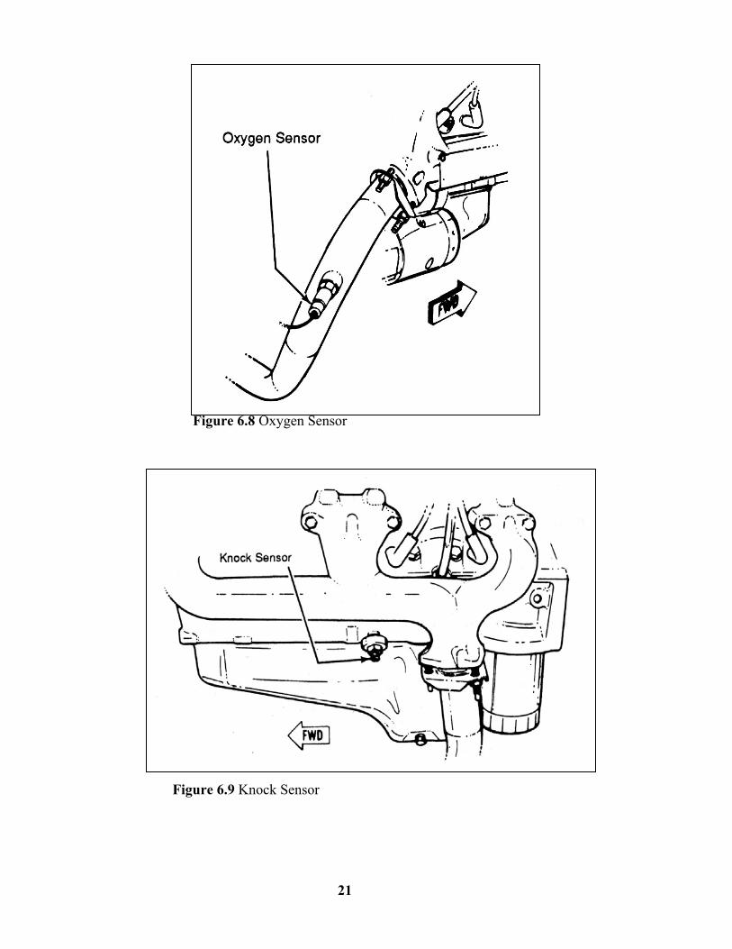
Figure 6.8 Oxygen Sensor Figure 6.9 Knock Sensor
21
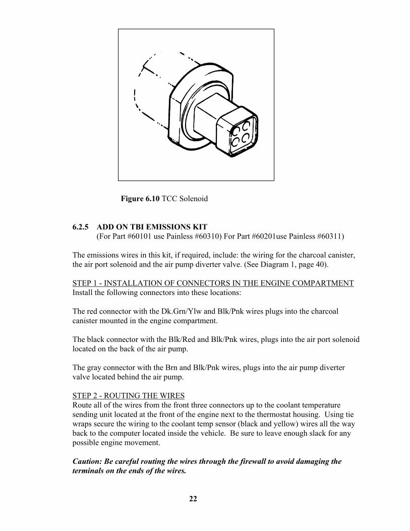
Figure 6.10 TCC Solenoid 6.2.5 ADD ON TBI EMISSIONS KIT
(For Part #60101 use Painless #60310) For Part #60201use Painless #60311)
The emissions wires in this kit, if required, include: the wiring for the charcoal canister, the air port solenoid and the air pump diverter valve. (See Diagram 1, page 40).
STEP 1 - INSTALLATION OF CONNECTORS IN THE ENGINE COMPARTMENT Install the following connectors into these locations:
The red connector with the Dk.Grn/Ylw and Blk/Pnk wires plugs into the charcoal canister mounted in the engine compartment.
The black connector with the Blk/Red and Blk/Pnk wires, plugs into the air port solenoid located on the back of the air pump.
The gray connector with the Brn and Blk/Pnk wires, plugs into the air pump diverter valve located behind the air pump.
STEP 2 - ROUTING THE WIRES Route all of the wires from the front three connectors up to the coolant temperature sending unit located at the front of the engine next to the thermostat housing. Using tie wraps secure the wiring to the coolant temp sensor (black and yellow) wires all the way back to the computer located inside the vehicle. Be sure to leave enough slack for any possible engine movement.
Caution: Be careful routing the wires through the firewall to avoid damaging the terminals on the ends of the wires.
22

STEP 3 - ATTACHING THE B+ POWER WIRES You will find that the three Blk/Pnk wires end near the back of the engine block. These wires should be spliced into the Pnk/Blk wire coming from the EGR solenoid connector. These wires can also be extended and connected to a 12 volt ignition only (switched) power source if you wish to do so.
STEP 4 - UNPLUGGING THE COMPUTER Caution: Removing the computer connectors from the computer while the ignition is on will damage the computer!
First, making sure that the ignition is off, unplug the two computer connectors by pushing down on the blue retaining tab and then pulling straight out and away from the computer. Be careful not to damage the computer pins! Remove the blue secondary locks from the black computer connectors by releasing the retaining clips and pulling them out from the back (wire) side of the connectors.
STEP 5 - CONNECTING THE CHARCOAL CANISTER WIRE AT THE COMPUTER Locate the 24-pin (the smaller of the two) computer connector. Using the attached wiring diagram for reference, look on the wire side of the connector housing for the corner marked "A-1". Once you have located this, count down the openings on the same side until you reach "A-3". You will insert the terminal on the Dk.Grn/Ylw wire (charcoal canister) into this opening, pushing in until the locking tang engages.
Note: The terminal will only fit one way into the connector; do not try to force the terminal.
STEP 6 - CONNECTING THE AIR DIVERTER WIRE AT THE COMPUTER Locate the 36-pin (the larger of the two) computer connector. In the same manner as you did in Step 5, locate the "C-1" side. This is the opening you will insert the terminal on the Blk/Red wire into. (air pump diverter valve)
STEP 7 - CONNECTING THE AIR PORT SOLENOID WIRE AT THE COMPUTER On the same connector, locate "C-2". This is the opening that you plug the terminal on the Brn wire (port solenoid) into, using the same procedure as in step 5 and 6.
Note: this wire has a second Brn wire spliced into it that should be set aside until Step 9.
STEP 8 - REPLACING THE COMPUTER CONNECTORS AT THE COMPUTER Replace the secondary locks on both connectors. Be careful to line up the "fingers" on the locks with the connector openings. Once you have the secondary locks in place then you can reinstall the computer connectors into the computer.
Caution: Use care when reinstalling the connectors, to avoid damaging the computer pins.
23

STEP 9 - ATTACHING THE AIR PUMP DIAGNOSTIC WIRE AT THE ALDL The Brn wire set aside in Step 6 goes to the ALDL connector (diagnostic plug). Route this Brn wire along the existing ALDL wiring until you come to the connector itself. The wire is inserted into the opening labeled "C" on the connector. (See Diagram 1, page 40).
Notes: Double check all routing making sure that there is enough slack to allow for any engine or other movement. Reinstall any grommets or other parts taken off.
Start and drive the vehicle for at least thirty minutes, then check for any trouble codes stored in the computer.
Painless Performance offers a technical assistance line to answer any questions that you may have. The number is (800) 423-9696. The phones are answered Monday through Friday from 8 AM to5 PM CST, not including holidays. Please leave a message if you are unable to reach us and we will return your call as soon as possible.
E-mail: [email protected] Web: www.painlessperformance.com
7.0 EARLY VERSION GM TUNED PORT INJECTION SYSTEM WIRE HARNESS
INSTALLATION INSTRUCTIONS
7.1 CONTENTS OF THE 60102 AND 60202 WIRE HARNESS KIT
Take inventory to see that you have everything you are supposed to have in this kit. If anything is missing, go to the dealer where you obtained the kit or contact Painless Performance at (800) 423-9696. The kit should contain the following items: • Main wire harness • Distributor, Oil Pressure and Fuel pump Adapters. • Fuel injection harness instructions P/N 90503 (this booklet)
The following optional parts are not included in the kit but are available from Painless Performance. • Computer Mounting Bracket, P/N 60301. See Figure 6.1. • Sensor and relay board mounting plate, P/N 60303. It is shown in Figure 6.2
with parts attached. (Parts not included) • Emission Control Device Harnesses. (Part #60312 and 60313)
7.2 ENGINE GROUP INSTALLATION
The engine group is designed to be separated into left side (driver) and right side (passenger) sections. Each side is tie wrapped separately, BUT NOT LABELED. The right side of the engine has the connectors for the idle air control, throttle position sensor, cold start switch, and coolant temp sensor, all of which ARE labeled. When you begin routing, FIRST separate the engine group into left and right sections and place them accordingly.
24

7.2.1 Before you connect any wires, separate the tail section from the engine group and place it out of the way.
7.2.2 Locate the two Blk/Wht wires in the harness that end in a single, large ring terminal and ground them to the engine.
7.2.3 Using Figure 7.5, Table 7.1 and the specific illustrations indicated in Table 7.1, connect the wiring as directed.
7.2.4 Green wire tagged A/C POWER attaches to the A/C compressor power wire at the compressor if the vehicle is so equipped. This will increase the engine idle RPM when the A/C is turned on.
7.3 DASH SECTION INSTALLATION
The dash section is installed in the same way as described in the throttle body installation instructions. Refer to Paragraph 6.2.1 and use the instructions there.
7.4 SENSOR AND RELAY INSTALLATION
Sensor and relay connections are illustrated in Figure 6.6B for pre-terminated wires. The following listing is for wires to be cut to length. Connect your wiring accordingly. Route and terminate the following wires in the under dash area;
7.4.1 Purple wire tagged VATS attaches to the VATS control module if so equipped.
7.4.2 Purple wire tagged BRAKE SWITCH attaches to the brake switch shown in FIGURE 6.5
7.4.3 Green/White wire tagged FAN RELAY GROUND is the ground for the fan relay if the computer is to be the control for the electric fan.
7.4.4 Pink/Black wire attaches to the ignition source described in 6.2.1 Paragraph "C"
7.4.5 Orange/Black and Black/ White wires attach according to your application as discussed in Section 4.1
NOTE: Any wire that you are not using should be taped and stored
7.5 TAIL SECTION INSTALLATION
The tail section wires are connected as described below.
7.5.1 Green - Tan/Blk - Purple wires in the white connector plug into the transmission, if so equipped.
7.5.2 Tan/White wire tagged FUEL PUMP attaches to the fuel pump. This is the power wire for the pump.
7.5.3 Brown wire tagged VEHICLE SPEED SENSOR attaches to the vehicle speed sensor as described in SECTION 4.1.4
25
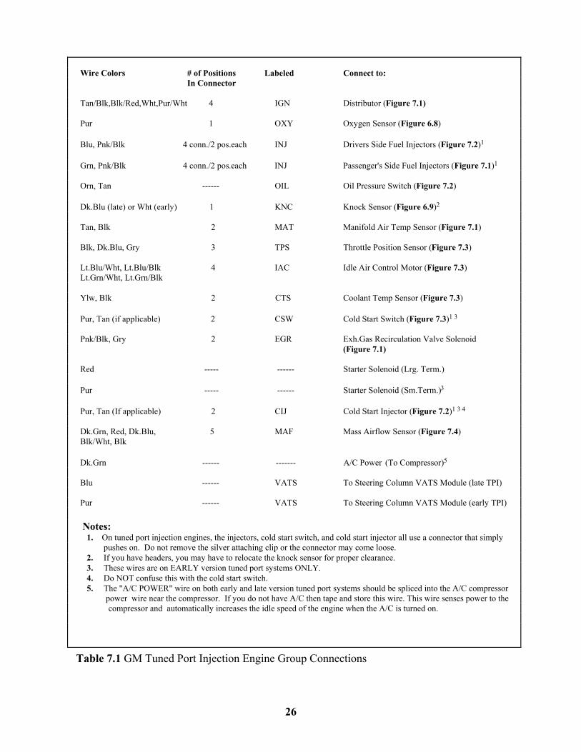
Table 7.1 GM Tuned Port Injection Engine Group Connections
26
Wire Colors # of Positions Labeled Connect to: In Connector Tan/Blk,Blk/Red,Wht,Pur/Wht 4 IGN Distributor (Figure 7.1) Pur 1 OXY Oxygen Sensor (Figure 6.8) Blu, Pnk/Blk 4 conn./2 pos.each INJ Drivers Side Fuel Injectors (Figure 7.2)1
Grn, Pnk/Blk 4 conn./2 pos.each INJ Passenger's Side Fuel Injectors (Figure 7.1)1
Orn, Tan ------ OIL Oil Pressure Switch (Figure 7.2) Dk.Blu (late) or Wht (early) 1 KNC Knock Sensor (Figure 6.9)2 Tan, Blk 2 MAT Manifold Air Temp Sensor (Figure 7.1) Blk, Dk.Blu, Gry 3 TPS Throttle Position Sensor (Figure 7.3) Lt.Blu/Wht, Lt.Blu/Blk 4 IAC Idle Air Control Motor (Figure 7.3) Lt.Grn/Wht, Lt.Grn/Blk Ylw, Blk 2 CTS Coolant Temp Sensor (Figure 7.3) Pur, Tan (if applicable) 2 CSW Cold Start Switch (Figure 7.3)1 3 Pnk/Blk, Gry 2 EGR Exh.Gas Recirculation Valve Solenoid (Figure 7.1)
Red ----- ------ Starter Solenoid (Lrg. Term.) Pur ----- ------ Starter Solenoid (Sm.Term.)3 Pur, Tan (If applicable) 2 CIJ Cold Start Injector (Figure 7.2)1 3 4 Dk.Grn, Red, Dk.Blu, 5 MAF Mass Airflow Sensor (Figure 7.4) Blk/Wht, Blk Dk.Grn ------ ------- A/C Power (To Compressor)5 Blu ------ VATS To Steering Column VATS Module (late TPI) Pur ------ VATS To Steering Column VATS Module (early TPI) Notes: 1. On tuned port injection engines, the injectors, cold start switch, and cold start injector all use a connector that simply pushes on. Do not remove the silver attaching clip or the connector may come loose. 2. If you have headers, you may have to relocate the knock sensor for proper clearance. 3. These wires are on EARLY version tuned port systems ONLY. 4. Do NOT confuse this with the cold start switch. 5. The "A/C POWER" wire on both early and late version tuned port systems should be spliced into the A/C compressor power wire near the compressor. If you do not have A/C then tape and store this wire. This wire senses power to the compressor and automatically increases the idle speed of the engine when the A/C is turned on.
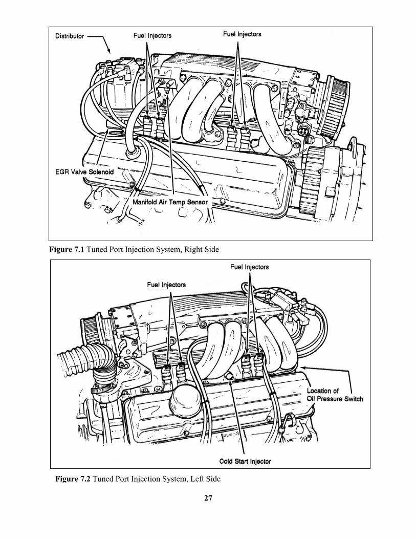
Figure 7.1 Tuned Port Injection System, Right Side
Figure 7.2 Tuned Port Injection System, Left Side
27
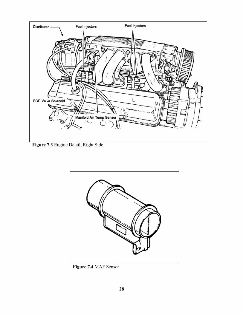
Figure 7.3 Engine Detail, Right Side Figure 7.4 MAF Sensor
28
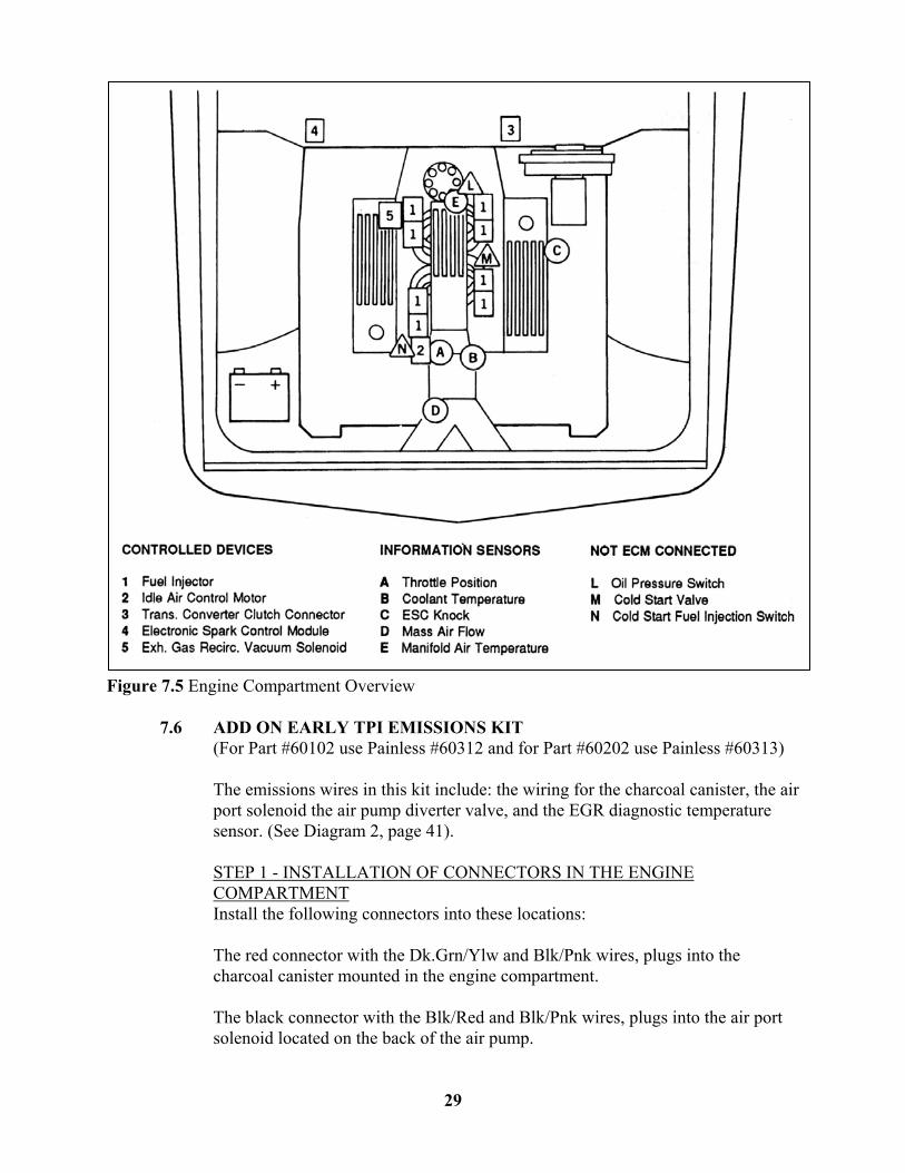
Figure 7.5 Engine Compartment Overview
7.6 ADD ON EARLY TPI EMISSIONS KIT (For Part #60102 use Painless #60312 and for Part #60202 use Painless #60313)
The emissions wires in this kit include: the wiring for the charcoal canister, the air port solenoid the air pump diverter valve, and the EGR diagnostic temperature sensor. (See Diagram 2, page 41).
STEP 1 - INSTALLATION OF CONNECTORS IN THE ENGINE COMPARTMENT Install the following connectors into these locations:
The red connector with the Dk.Grn/Ylw and Blk/Pnk wires, plugs into the charcoal canister mounted in the engine compartment.
The black connector with the Blk/Red and Blk/Pnk wires, plugs into the air port solenoid located on the back of the air pump.
29
The gray connector with the Brn and Blk/Pnk wires, plugs into the air pump diverter valve located behind the air pump.
The black connector with the single Dk.Grn wire plugs into the EGR valve diagnostic temperature connector located under the center of the intake plenum.
STEP 2 - ROUTING THE WIRES Route all of the wires from the front three connectors up to the coolant temperature sending unit located at the front of the engine next to the thermostat housing. Using tie wraps secure the wiring to the coolant temp sensor (black and yellow) wires all the way back to the computer located inside the vehicle. Be sure to leave enough slack for any possible engine movement.
Caution: Be careful routing the wires through the firewall to avoid damaging the terminals on the ends of the wires.
STEP 3 - ATTACHING THE B+ POWER WIRES You will find that the three Blk/Pnk wires, end near the back of the engine block. These wires should be spliced into the Pnk/Blk wire coming from the EGR solenoid connector. These wires can also be extended and connected to a 12 volt ignition only (switched) power source if you wish to do so.
STEP 4 - UNPLUGGING THE COMPUTER Caution: Removing the computer connectors from the computer while the ignition is on will damage the computer!
First making sure that the ignition is off, unplug the two computer connectors by pushing down on the blue retaining tab and then pulling straight out and away from the computer. Be careful not to damage the computer pins! Remove the blue secondary locks from the black computer connectors by releasing the retaining clips and pulling them out from the back (wire) side of the connectors.
STEP 5 - CONNECTING THE CHARCOAL CANISTER WIRE AT THE COMPUTER Locate the 24-pin (the smaller of the two) computer connector. Using the attached wiring diagram for reference, look on the wire side of the connector housing for the corner marked "A-1". Once you have located this, count down the openings on the same side until you reach "A-3". You will insert the terminal on the Dk.Grn/Ylw wire (charcoal canister) into this opening, pushing in until the locking tang engages.
Note: The terminal will only fit one way into the connector; do not try to force the terminal.
STEP 6 - CONNECTING THE AIR PORT SOLENOID WIRE AT THE COMPUTER
30
On the same connector, locate "A-2". This is the opening that you plug the terminal on the Brn wire (port solenoid) into, using the same procedure as in step 5.
Note: this wire has a second Brn wire spliced into it that should be set aside until Step 10.
STEP 7 - CONNECTING THE AIR DIVERTER WIRE AT THE COMPUTER Locate the 36-pin (the larger of the two) computer connector. In the same manner as you did in Step 5 and 6, locate the "C-1" side. When you have done this, then count down the same side one opening to "C-2". This is the opening you will insert the terminal on the Blk/Red wire into. (air pump diverter valve)
STEP 8 - CONNECTING THE EGR TEMPERATURE WIRE AT THE COMPUTER On the same side of the same connector as you were using in Step 7, find "C-15". This is the opening for the terminal on the Dk.Grn wire (EGR diagnostic temp).
STEP 9 - REPLACING THE COMPUTER CONNECTORS AT THE COMPUTER Replace the secondary locks on both connectors. Be careful to line up the "fingers" on the locks with the connector openings. Once you have the secondary locks in place then you can reinstall the computer connectors into the computer.
Caution: use care when reinstalling the connectors, to avoid damaging the computer pins.
STEP 10 - ATTACHING THE AIR PUMP DIAGNOSTIC WIRE AT THE ALDL The brown wire set aside in step 6 goes to the ALDL connector (diagnostic plug). Route this brown wire along the existing ALDL wiring until you come to the connector itself. The wire is inserted into the opening labeled "C" on the connector. (See Diagram 2, page 41)
Notes: Double check all routing making sure that there is enough slack to allow for any engine or other movement. Reinstall any grommets or other parts taken off.
Start and drive the vehicle for at least thirty minutes, then check for any trouble codes stored in the computer. Painless Performance offers a technical assistance line to answer any questions that you may have. The number is (800) 423-9696. The phones are answered Monday through Friday from 8 AM to5 PM CST, not including holidays. Please leave a message if you are unable to reach us and we will return your call as soon as possible.
E-mail: [email protected] Web: www.painlessperformance.com
31

8.0 LATE VERSION GM TUNED PORT INJECTION SYSTEMS
INSTALLATION INSTRUCTIONS 8.1 CONTENTS OF THE 60103 AND 60203 WIRE HARNESS KIT
Take inventory to see that you have everything you are supposed to have in this kit. If anything is missing; go to the dealer where you obtained the kit or contact Painless Performance at (800) 423-9696. The kit should contain the following items: • Main wire harness with connectors on the ends of many of the wires. • Distributor, fuel pump relay and Oil Pressure Adapters. • Fuel injection harness instructions P/N 90503 (this booklet).
The following optional parts are not included in the kit but are available from Painless Performance. • Computer Mounting Bracket, P/N 60302. See Figure 6.1. • Sensor and relay board mounting plate, P/N 60303. It is shown in Figure
6.2 • Emission Control Device Harnesses. (Part #60314 and 60315)
Notes: All factory computer proms (chips), for the late TPI Systems and some early TPI computers have the vehicle anti-theft system programmed into them. An after-market chip must be used with the VATS removed or the original steering column and VATS module must be used or the engine will not start.
8.2 ENGINE GROUP INSTALLATION
The engine group is connected as described in Section 7.2 of these instructions except that the engine will not have a mass airflow (MAF) sensor. Do not forget to ground the two Blk/Wht wires to the engine.
8.3 DASH GROUP INSTALLATION
The dash section is connected as described in Paragraph 6.2.1 of these instructions.
8.4 SENSOR AND RELAY INSTALLATION
The sensor and relays are connected according to SECTION 7.4 of these instructions, using Table 6.2 and Figure 6.6, Item C.
8.5 TAIL SECTION INSTALLATION
The tail section wires consist of:
32
A. Purple and Yellow wires tagged VEHICLE SPEED SENSOR, after cutting to proper length, attach to the two wires coming out of the Part Number 60116 speed sensor. It makes no difference how the wires are attached. The connector may have to be cut off the 60116 speed sensor to connect to it. B. Gray wire tagged FUEL PUMP is the power wire for the pump. Route and cut to length. C. Lt.blu, tan/blk and purple wires, in the white connector, plugs into 700R4 if so equipped.
9.0 TROUBLE SHOOTING INSTRUCTIONS
If you are having trouble with your engine running badly or not running at all, first perform basic trouble shooting (checking for faulty connections, spark, timing, fuel pressure, etc.) then see is the computer has stored a trouble code in its memory.
9.1 THE "CHECK ENGINE" LIGHT
Normally, the "check engine" light should come on when the ignition is initially turned on, then go out a few moments after the engine starts running. If it reappears, or stays on while the engine is running, the computer has detected a problem and a trouble code has been set.
9.1.1 The computer identifies particular trouble codes by flashing the "check
engine" light in a certain way. The codes are read by counting the flashes:
A. The first digit (the "tens" digit) of the code is flashed quickly, followed by a brief pause, then the second digit (or "ones" digit) is flashed, followed by a longer pause. For example, three (3) quick flashes followed by a brief pause followed by two (2) flashes indicates code 32.
B. The code will repeat itself three (3) times. The next code, if any,
will be displayed in the same manner.
Note: When you access the codes from the computer a code 12 (one flash followed by two flashes) will first be displayed. THIS DOES NOT INDICATE A PROBLEM. Code 12 will be flashed 3 times, followed by the particular trouble codes, if any. If the computer merely flashes code 12 there are no trouble codes stored. Code 12 means the engine is not running.
9.2 RETRIEVING TROUBLE CODES FROM THE COMPUTER
9.2.1 In order to retrieve the trouble codes stored in the computer, locate the
Assembly Line Diagnostic Link (ALDL) connector (installed and connected in Paragraph 6.2.1). Turn the ignition on, BUT DO NOT START THE CAR. Connect a jumper wire from ALDL terminal "A" to terminal "B" (see Figure 6.3) and observe the "check engine" light.
33
9.2.2 After you have read any codes (remember the normal code 12), write them down for reference. Remove the jumper wire from the ALDL connector.
9.2.3 Take the codes one at a time and match them to the codes in Table 9.1. This will tell you in which circuit the computer has detected a problem.
Note: A code indicates a problem in a specific circuit, NOT THAT A PARTICULAR PART IS BAD.
9.2.4 Before taking more extensive corrective actions for any trouble code,
make sure that all connections on the indicated circuit, INCLUDING THE COMPUTER, are clean and tight. Inspect the wiring in the circuit for any broken, shorted, or exposed wires. Finally, insure all ground wires are clean and secure.
9.2.5 If you are getting a code from your computer and need to clear the code, other than code 12, after you have replaced a part, readjusted a part, etc. You can do this by making sure the ignition is off and then disconnecting the negative battery cable for a minimum of two minutes. After the two minutes are up then you simply reconnect the negative battery cable and recheck the system for codes.
9.3 WHEN TO CALL PERFECT PERFORMANCE PRODUCTS' TECH LINE
9.3.1 These harness kits have been built with the highest regard to strict quality control. Before calling us please double-check all connections and perform normal basic trouble shooting (fuel pressure, timing, ignition system, etc.).
9.3.2 If you have any questions concerning the installation of this harness or are
having trouble in general; feel free to call the Painless Performance tech line at (800) 423-9696. Calls are answered from 8 AM to 5 PM CST, Monday through Friday, except holidays. Please leave a message if you are unable to reach us and we will return your call as soon as possible.
E-mail: [email protected] Web: www.painlessperformance.com
34
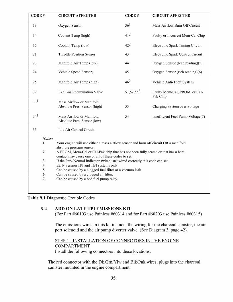
Table 9.1 Diagnostic Trouble Codes 9.4 ADD ON LATE TPI EMISSIONS KIT (For Part #60103 use Painless #60314 and for Part #60203 use Painless #60315)
The emissions wires in this kit include: the wiring for the charcoal canister, the air port solenoid and the air pump diverter valve. (See Diagram 3, page 42).
STEP 1 - INSTALLATION OF CONNECTORS IN THE ENGINE COMPARTMENT Install the following connectors into these locations:
The red connector with the Dk.Grn/Ylw and Blk/Pnk wires, plugs into the charcoal canister mounted in the engine compartment.
35
CODE # CIRCUIT AFFECTED CODE # CIRCUIT AFFECTED 13 Oxygen Sensor 361 Mass Airflow Burn Off Circuit 14 Coolant Temp (high) 412 Faulty or Incorrect Mem-Cal Chip 15 Coolant Temp (low) 422 Electronic Spark Timing Circuit 21 Throttle Position Sensor 43 Electronic Spark Control Circuit 23 Manifold Air Temp (low) 44 Oxygen Sensor (lean reading)(5) 24 Vehicle Speed Sensor; 45 Oxygen Sensor (rich reading)(6) 25 Manifold Air Temp (high) 462 Vehicle Anti-Theft System 32 Exh.Gas Recirculation Valve 51,52,552 Faulty Mem-Cal, PROM, or Cal-
Pak Chip 331 Mass Airflow or Manifold
Absolute Pres. Sensor (high) 53 Charging System over-voltage 341 Mass Airflow or Manifold 54 Insufficient Fuel Pump Voltage(7)
Absolute Pres. Sensor (low) 35 Idle Air Control Circuit
Notes: 1. Your engine will use either a mass airflow sensor and burn off circuit OR a manifold
absolute pressure sensor. 2. A PROM, Mem-Cal or Cal-Pak chip that has not been fully seated or that has a bent
contact may cause one or all of these codes to set. 3. If the Park/Neutral Indicator switch isn't wired correctly this code can set. 4. Early version TPI and TBI systems only. 5. Can be caused by a clogged fuel filter or a vacuum leak. 6. Can be caused by a clogged air filter. 7. Can be caused by a bad fuel pump relay.

The black connector with the Blk/Red and Blk/Pnk wires, plugs into the air port solenoid located on the back of the air pump.
The gray connector with the Brn and Blk/Pnk wires, plugs into the air pump diverter valve located behind the air pump.
STEP 2 - ROUTING THE WIRES Route all of the wires from the front three connectors up to the coolant temperature sending unit located at the front of the engine next to the thermostat housing. Using tie wraps secure the wiring to the coolant temp sensor (black and yellow) wires all the way back to the computer located inside the vehicle. Be sure to leave enough slack for any possible engine movement.
Caution: Be careful routing the wires through the firewall to avoid damaging the terminals on the ends of the wires.
STEP 3 - ATTACHING THE B+ POWER WIRES You will find that the three Blk/Pnk wires, end near the back of the engine block. These wires should be spliced into the Pnk/Blk wire coming from the EGR solenoid connector. These wires can also be extended and connected to a 12 volt ignition only (switched) power source if you wish to do so.
STEP 4 - UNPLUGGING THE COMPUTER Caution: Removing the computer connectors from the computer while the ignition is on will damage the computer!
First making sure that the ignition is off, unplug the three computer connectors by pushing down on the blue retaining tab and then pulling straight out and away from the computer. Be careful not to damage the computer pins! Remove the blue secondary locks from the yellow computer connector by releasing the retaining clips and pulling them out from the back (wire) side of the connector.
STEP 5 - CONNECTING THE CHARCOAL CANISTER WIRE AT THE COMPUTER Using the attached wiring diagram for reference, look on the wire side of the connector housing for the corner marked "F-1". Once you have located this, count down the openings on the same side until you reach "F-7". You will insert the terminal on the Dk.Grn/Ylw wire (charcoal canister) into this opening, pushing in until the locking tang engages.
Note: The terminal will only fit one way into the connector; do not try to force the terminal.
STEP 6 - CONNECTING THE AIR DIVERTER WIRE AT THE COMPUTER On the same connector, in the same manner as you did in Step 5, locate the "F-4" side. This is the opening you will insert the terminal on the Blk/Red wire into. (air pump diverter valve)
36
STEP 7 - CONNECTING THE AIR PORT SOLENOID WIRE AT THE COMPUTER On the same connector, locate "F-2". This is the opening that you plug the terminal on the Brn wire (port solenoid) into, using the same procedure as in step 5 and 6.
STEP 8 - REPLACING THE COMPUTER CONNECTORS AT THE COMPUTER Replace the secondary locks on the connector. Be careful to line up the "fingers" on the locks with the connector openings. Once you have the secondary locks in place then you can reinstall the computer connectors into the computer.
See Drawing at the back of this manual.
Caution: use care when reinstalling the connectors, to avoid damaging the computer pins.
Notes: Double-check all routing making sure that there is enough slack to allow for any engine or other movement. Reinstall any grommets or other parts taken off.
Start and drive the vehicle for at least thirty minutes, then check for any trouble codes stored in the computer.
Painless Performance offers a technical assistance line to answer any questions that you may have. The number is (800) 423-9696. The phones are answered Monday through Friday from 8 AM to5 PM CST, not including holidays. Please leave a message if you are unable to reach us and we will return your call as soon as possible.
E-mail: [email protected] Web: www.painlessperformance.com
MOST COMMONLY ASKED QUESTIONS ABOUT GM ELECTRONIC FUEL INJECTION Q WHAT'S THE DIFFERENCE BETWEEN THE EARLY AND LATE TPI UNITS?
A 1. THE EARLY TPI UNITS, 1986 THRU 1989, HAVE A MASS AIR FLOW SENSOR TO MEASURE THE AMOUNT OF AIR ENTERING THE ENGINE SO THE COMPUTER WILL KNOW HOW MUCH FUEL TO INJECT. 2. MOST EARLY TPI’S HAVE A 9TH INJECTOR TO INJECT FUEL, DURING COLD
STARTING, TO RICHEN THE MIXTURE LIKE A CHOKE. 3. THE LATE TPI, 1990 THRU 1992, USES A MAP (MANIFOLD, ATMOSPHERIC PRESSURE)
SENSOR, RUN BY VACUUM, TO CALCULATE THE AMOUNT OF FUEL TO INJECT. 4. THE LATE TPI UNITS DO NOT HAVE A 9TH INJECTOR; INSTEAD THEY INJECT
EXTRA FUEL FROM ALL 8 INJECTORS DURING COLD STARTING.
Q WHAT'S THE EASIEST WAY TO TELL WHAT COMPUTER I HAVE?
A THE EARLY TPI AND ALL TBI'S HAVE COMPUTERS WITH 2 PORTS FOR THE WIRING HARNESS TO PLUG INTO WHERE THE LATE TPI COMPUTERS HAVE 3 PORTS FOR THE WIRING HARNESS.
37

Q CAN I CHANGE MY EARLY TPI OVER TO THE LATE STYLE?
A YES. YOU CAN MAKE AN EARLY UNIT A LATE STYLE BUT, YOU CANNOT MAKE A LATE STYLE AN EARLY BECAUSE OF THE 9TH INJECTOR.
Q WHAT ALL DO I HAVE TO CHANGE TO MAKE MY EARLY UNIT OPERATE LIKE A LATE UNIT?
A 1 YOU MUST USE PAINLESS PART NUMBER 60103 OR 60203. 2 YOU MUST CHANGE THE COMPUTER TO THE LATE STYLE. 3 REMOVE THE MAF SENSOR AND ADD A MAP SENSOR. 4 CHANGE THE KNOCK SENSOR. 5 ELIMINATE THE ELECTRONIC SPARK CONTROL MODULE.
Q WHAT IS THE MOST COMMON PROBLEM WITH FUEL INJECTION SYSTEMS?
A LACK OF PROPER FUEL PRESSURE WHICH CAUSES LOW POWER, STUMBLE, BACKFIRE, NO THROTTLE RESPONSE AND THE LIST GOES ON AND ON.
Q CAN I KEEP MY HIGH PERFORMANCE CAMSHAFT IN THE ENGINE, WHEN I INSTALL A TPI UNIT?
A YES. IF YOU USE THE EARLY STYLE WITH THE MAF SENSOR. SINCE THE LATE STYLE MEASURES ENGINE VACUUM (MAP SENSOR) A CAM OTHER THAN STOCK MODIFIES (LOWERS) ENGINE VACUUM AND THE MAP SENSOR WILL THEN ASSUME THE THROTTLE IS IN AN OPEN POSITION AND WILL INJECT EXTRA FUEL TO COMPENSATE. THE ENGINE WILL THEN RUN ROUGH AND BE IN A FUEL RICH STATE.
Q MUST I HAVE MY FUEL PUMP INSIDE THE FUEL TANK?
A NO. INSIDE THE TANK IS THE BEST BECAUSE THE FUEL COOLS THE PUMP. IF YOU ARE USING AN EXTERNAL PUMP, MOUNT IT AS CLOSE TO THE TANK AS POSSIBLE AND BE SURE TO USE A BYPASS FUEL REGULATOR SO EXCESS PRESSURE CAN BE BLED OFF TO THE TANK.
Q DO I HAVE TO RUN AN AFTERMARKET CHIP IN MY COMPUTER OR CAN I KEEP THE STOCK ONE?
A IN ALMOST ALL CASES THE FACTORY CHIP WILL REQUIRE REPLACEMENT BECAUSE OF THE VATS (VEHICLE ANTI-THEFT SYSTEM) PROGRAMMED INTO IT. THIS WILL CAUSE THE ENGINE NOT TO START AND RUN.
Q WHEN INSTALLING A TPI UNIT AND REMOVING A CARBURETOR WHAT MODIFICATIONS TO THE ENGINE MUST I DO?
A 1. FUEL PUMP REPLACEMENT ALONG WITH A RETURN FUEL LINE. 2. AN OXYGEN SENSOR ADAPTOR WILL BE NEEDED IN THE EXHAUST SYSTEM. 3. THE BRACKETS FOR THE ALTERNATOR AND A/C COMPRESSOR WILL NEED TO BE
MODIFIED OR REPLACED. 4. DIFFERENT STYLE AIR CLEANER WILL BE REQUIRED. 5. DIFFERENT IGNITION DISTRIBUTOR WILL BE REQUIRED. 6. THROTTLE LINKAGE, WIRING AND OTHER SMALL PARTS WILL NEED TO BE REPLACED
OR REWORKED.
Q WHAT MODIFICATIONS TO MY EXISTING WIRING IS NEEDED TO INSTALL FUEL INJECTION?
A FACTORY STYLE ELECTRONIC FUEL INJECTION (EFI) SYSTEMS ARE STAND ALONE UNITS WHICH MEANS THAT THEY DO NOT REQUIRE A CERTAIN STYLE CHASSIS WIRING SYSTEM TO OPERATE.
38

Q WHAT WIRES NEED TO BE HOOKED UP IN EFI SYSTEMS OTHER THAN THE SENSORS, ETC.?
A USUALLY THERE ARE ONLY 4 WIRES TO BE HOOKED UP: 1. MAIN POWER INPUT FROM THE BATTERY SUPPLY. 2. IGNITION POWER WHEN THE KEY IS ON. 3. A GOOD GROUND. 4. STARTER ACTIVATION INPUT, THIS TELLS THE COMPUTER THAT THE ENGINE IS
BEING TURNED OVER AND TO INJECT FUEL SO IT WILL START.
Q IS THE LARGE, HEI STYLE, DISTRIBUTOR BETTER OR WORSE THAN THE SMALLER EXTERNAL COIL STYLE?
A THEY BOTH OPERATE ON THE SAME PRINCIPAL AND HAVE ABOUT THE SAME OUTPUT, BUT THE LARGER HEI STYLE IS EASIER TO HOOK UP.
39
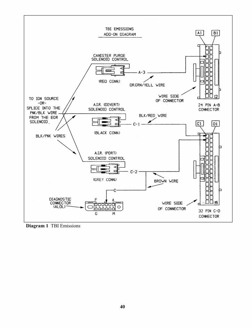
Diagram 1 TBI Emissions
40
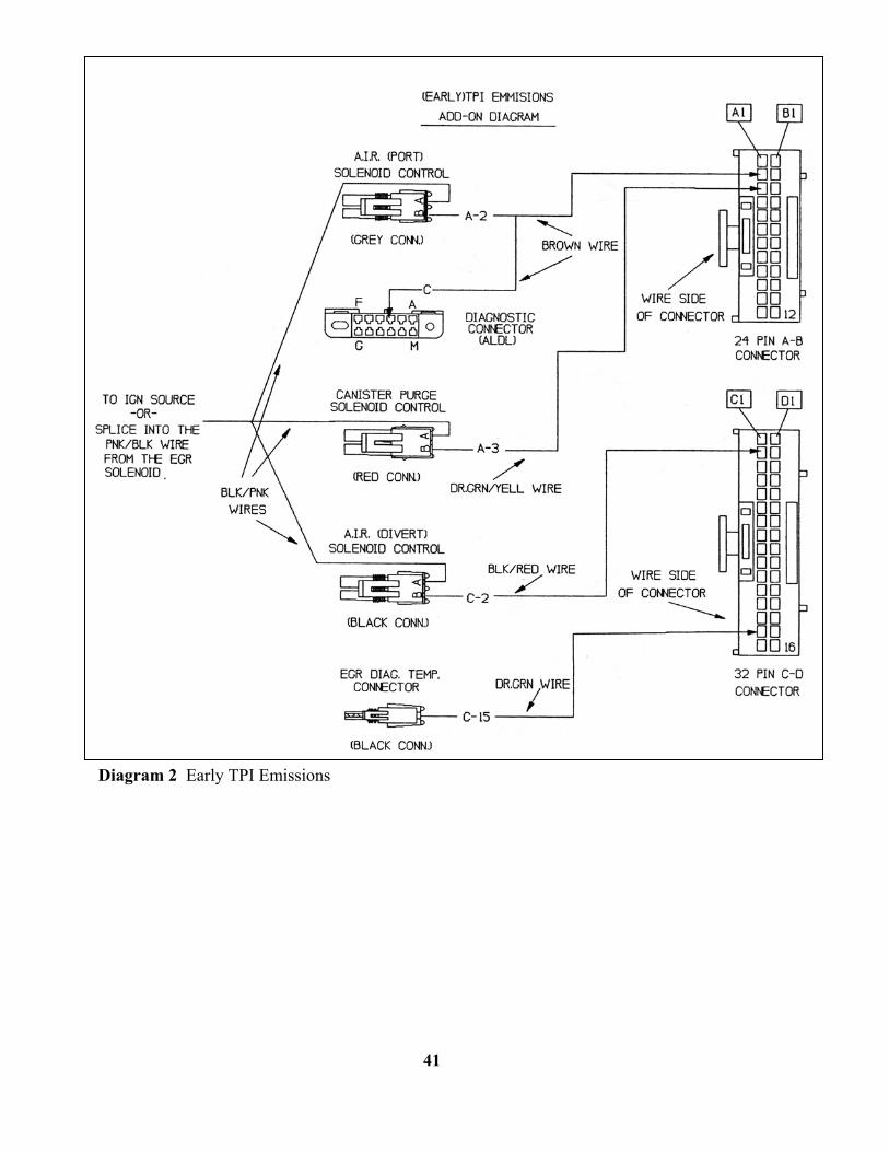
Diagram 2 Early TPI Emissions
41
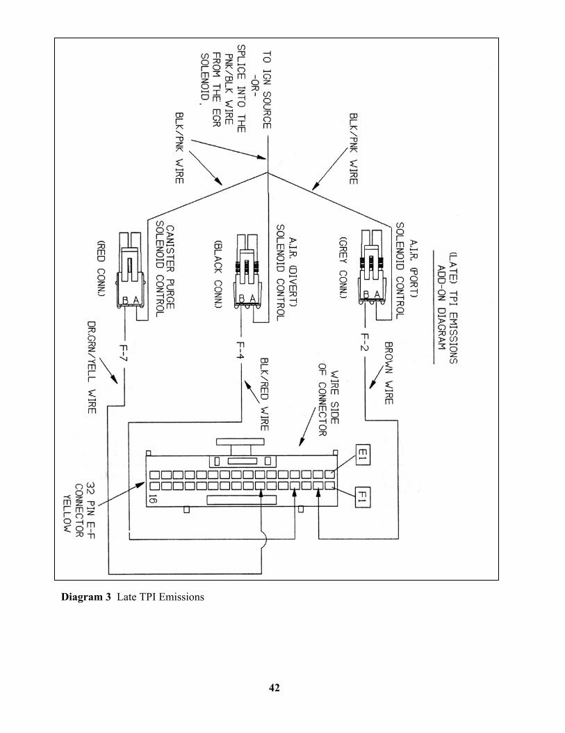
Diagram 3 Late TPI Emissions
42
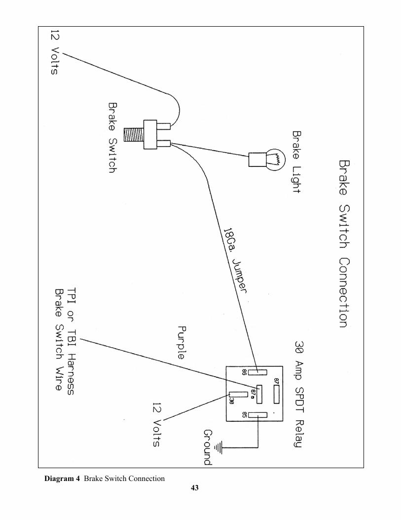
Diagram 4 Brake Switch Connection 43

NOTES
44

SUPPLEMENT REGARDING
EMISSION HARNESSES
For: Part #’s 60101, 60102, 60103, 60201, 60202, 60203
This electronic fuel injection harness has all wires required for initial startup and proper closed loop operation of the engine. If your vehicle requires harnesses to activate the AIR Port Solenoid Control, AIR Diverter Solenoid Control or Canister Purge Solenoid Control to meet local emission standards please contact your local Painless dealer to purchase the emissions harness.
Fuel Inj. Harness Part # Emission Harness Part # 60101 60310 60102 60312 60103 60314 60201 60311 60202 60313 60203 60315
NOTE: These emission harnesses do not prevent the operation
of the vehicle’s engine and may be added at any time. G:\SHARE\Instructions\MS Word\MANUALS\90503\90503 Manual Supplement.doc 09/28/01