Embed Size (px)
Citation preview

www.speedfitUFH.co.uk
For models:
JGSTATW2WJGSTATW2BJGSTATW1WJGSTATW1B
Instruction Manual
Wireless Thermostats230v and Battery Operated

1 x Instruction Manual JGSTATW2
4x AAA Batteries
JGSTATW1
www.speedfitUFH.co.uk
For models:
JGSTATW2WJGSTATW2BJGSTATW1WJGSTATW1B
Instruction Manual
Wireless Thermostats230v and Battery Operated
Fixing screws
Box contents:
02 JGSTATW Instruction Manual
Contents
Instruction manual:• Box contents• Introduction• Product Compliance• System options overview• Installation • Parameter settings• Error codes• User guide• Installers notes
Icons used in this manual:
Safety
Important info
Your benefit
For latest PDF instruction manualplease go to www.speedfitUFH.co.uk

Introduction. Thank you for purchasingone of our Speedfit Aura WirelessThermostat models. It must be used withthe JGCO Wireless Coordinator. TheWireless Coordinator allowscommunication with other devices in theAura Wireless system range includingwiring centre, system receiver and TRV.
Product Compliance. Thisproduct is CE compliant andmeets the following ECDirectives: RoHS2 2011/65/EU, Electro-Magnetic Compatibilitydirective 2004/108/EC andLow voltage directive2006/95/EC.
Safety Information. Use inaccordance with theregulations. The Aura JGSTAT2is to be used for room controlof heating and hot watersystems inside buildings.
JGWCW
JGBR JGTRV
JGSTATW
JGCO
03www.speedfitUFH.co.uk
Product Compliance & Safety Information
We hope you enjoythis product...

04 JGSTATW Instruction Manual
Product Compliance & Safety Information
Emergency. Switch off thevoltage to the individualthermostat, wiring centre orcomplete system.
Sources of danger. Thethermostat must be disconnectedfrom mains supply beforeremoving the cover.
For the installer. Please enterany parameter changes in theInstaller Notes section (pages90 and 91).
Installer parameter settings.Aura Wireless Thermostats areequipped with an InstallerParameter section (see page 40).This must only be entered by theinstaller or a competent person.Changing these parameters canhave a serious effect on yourheating system.
230V AC
Warning. This product must befitted by a competent person.Installation must comply with theguidance, standards andregulations applicable to thelocation where the product isinstalled. Failure to comply with therequirements of the relevantguidance, standards andregulations could lead toprosecution, injury or death.
These instructions are applicable to theAura models stated on the front cover ofthis Instruction Manual only.
Warning. Always isolate theAC Mains supply beforeinstalling or working on anycomponents that require 230vAC 50Hz supply.
Programmable RoomThermostat (PRT)
* Grouping and timer option only available when used with wiring centre.
UFH Manifold
Wiring Centre
Radiator
Boiler
Hot Water
TRV
Towel Rails
05www.speedfitUFH.co.uk
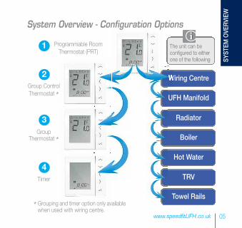
System Overview - Configuration Options
Group ControlThermostat *
GroupThermostat *
Timer
1
2
3
4
The unit can beconfigured to eitherone of the following SYSTEM
OVERVIEW
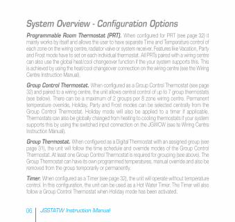
Programmable Room Thermostat (PRT). When configured for PRT (see page 32) itmainly works by itself and allows the user to have separate Time and Temperature control ofeach zone on the wiring centre, radiator valve or system receiver. Features like Vacation, Partyand Frost mode have to set on each individual thermostat. All PRTs paired with a wiring centrecan also use the global heat/cool changeover function if the your system supports this. Thisis achieved by using the heat/cool changeover connection on the wiring centre (see the WiringCentre Instruction Manual).
Group Control Thermostat. When configured as a Group Control Thermostat (see page32) and paired to a wiring centre, the unit allows central control of up to 7 group thermostats(see below). There can be a maximum of 2 groups per 8 zone wiring centre. Permanenttemperature override, Holiday, Party and Frost modes can be selected centrally from theGroup Control Thermostat. Holiday mode will also be applied to a timer if applicable.Thermostats can also be globally changed from heating to cooling thermostats if your systemsupports this by using the switched input connection on the JGWCW (see te Wiring CentreInstruction Manual).
Group Thermostat. When configured as a Digital Thermostat with an assigned group (seepage 31), the unit will follow the time schedule and override modes of the Group ControlThermostat. At least one Group Control Thermostat is required for grouping (see above). TheGroup Thermostat can have its own programmed temperatures, manual override and also beremoved from the group temporarily or permanently.
Timer. When configured as a Timer (see page 32), the unit will operate without temperaturecontrol. In this configuration, the unit can be used as a Hot Water Timer. The Timer will alsofollow a Group Control Thermostat when Holiday mode has been activated.
06 JGSTATW Instruction Manual
System Overview - Configuration Options

JGCO Wireless coordinator required for communication between these devices.
JGWCWJGSTATW
JGTRVJGBR
JGCO
07www.speedfitUFH.co.uk
System Overview - Wireless Coordinator
SYSTEM
OVERVIEW

The thermostat can communicatewith all of these Aura devices.
JGBR configured to Boiler Receiver (RX1).Refer to JGBR Instruction Manual.
JGBR configured tosingle room receiver(RX2). Refer to JGBRBoiler ReceiverInstruction Manual.
Max 3 TRV per thermostat.
UNDERFLOOR HEATING MANIFOLD
08 JGSTATW Instruction Manual
System Overview - Speedfit Aura
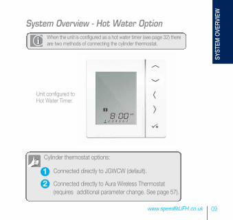
When the unit is configured as a hot water timer (see page 32) thereare two methods of connecting the cylinder thermostat.
09www.speedfitUFH.co.uk
System Overview - Hot Water Option
Unit configured to Hot Water Timer.
Cylinder thermostat options:
Connected directly to JGWCW (default).
Connected directly to Aura Wireless Thermostat (requires additional parameter change. See page 57).
12
SYSTEM
OVERVIEW
10 JGSTATW Instruction Manual
System Overview - Hot Water Option
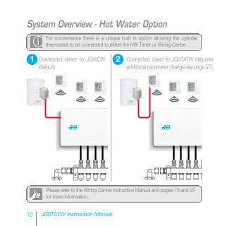
Please refer to the Wiring Centre Instruction Manual and pages 15 and 20for more information.
Connected direct to JGWCW(default).
1
For convenience there is a unique built in option allowing the cylinderthermostat to be connected to either the HW Timer or Wiring Centre.
2 Connected direct to JGSTATW (requiresadditional parameter change see page 57).
Not Do not insta Only the te
Not Do not insta Only the te
Not Do not insta Only the te
Not Do not insta Only the te
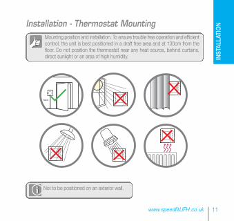
Mounting position and installation. To ensure trouble free operation and efficientcontrol, the unit is best positioned in a draft free area and at 130cm from thefloor. Do not position the thermostat near any heat source, behind curtains,direct sunlight or an area of high humidity.
11www.speedfitUFH.co.uk
Installation - Thermostat Mounting
Not to be positioned on an exterior wall.
INSTALLATION
130cm

60mm
12 JGSTATW Instruction Manual
Installation - Thermostat Mounting (JGSTATW1)
1 2
3
Carefully remove the front housing.
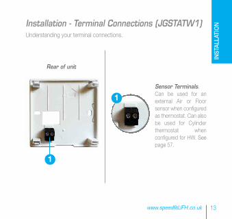
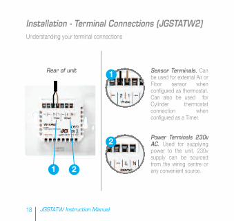
Understanding your terminal connections.
Sensor Terminals. Can be used for anexternal Air or Floorsensor when configuredas thermostat. Can alsobe used for Cylinderthermostat whenconfigured for HW. Seepage 57.
13www.speedfitUFH.co.uk
Installation - Terminal Connections (JGSTATW1)
1
1
Rear of unit
INSTALLATION

Note: If you are using an external sensor, the unit has to beconfigured for External Air Sensor or Floor Protection Sensor pleasesee Device Parameter setting page 57.
Speedfit Aura External sensor (Sold separately).
14 JGSTATW Instruction Manual
Installation - Thermostat External Sensor (JGSTATW1)
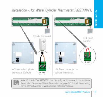
Note: Optional - The JGSTATW1 can be configured for connection to a cylinderthermostat. Please see Device Parameters on page 57. For additional wiringcentre information refer to Wiring Centre Instruction Manual.
15www.speedfitUFH.co.uk
Installation - Hot Water Cylinder Thermostat (JGSTATW1)
WC connected cylinderthermostat (Default).
HW Timer connected tocylinder thermostat.
Link must be fitted
ZONE 1
SL N L SL N L SL N L SL N L SL N L SL N L SL N LSL N L
ZONE 2 ZONE 3 ZONE 4 ZONE 5 ZONE 6 ZONE 7 ZONE 8
5 x 20mm
5 x 20mm
IN OUT
Cylinder thermostat
ZONE 1
SL N L SL N L SL N L SL N L SL N L SL N L SL N LSL N L
ZONE 2 ZONE 3 ZONE 4 ZONE 5 ZONE 6 ZONE 7 ZONE 8
5 x 20mm
5 x 20mm
IN OUT
INSTALLATION
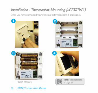
Once you have connected your choice of external sensor (if applicable).
Insert batteriesNote: Please proceedto page 23.
16 JGSTATW Instruction Manual
1 2
3 4
Installation - Thermostat Mounting (JGSTATW1)
17www.speedfitUFH.co.uk
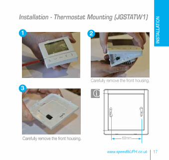
Carefully remove the front housing. 60mm
Installation - Thermostat Mounting (JGSTATW1)
1 2
3Carefully remove the front housing.
INSTALLATION
Rear of unit
Power Terminals 230vAC. Used for supplyingpower to the unit. 230vsupply can be sourcedfrom the wiring centre orany convenient source.
Sensor Terminals. Canbe used for external Air orFloor sensor whenconfigured as thermostat.Can also be used forCylinder thermostatconnection whenconfigured as a Timer.
18 JGSTATW Instruction Manual
Understanding your terminal connections
Installation - Terminal Connections (JGSTATW2)
1
2
1 2

Note: If you are using an external sensor, the unit has to beconfigured for External Air Sensor or Floor Protection Sensor.Please see device parameter setting page 57.
Aura External sensor (Sold separately).
19www.speedfitUFH.co.uk
Installation - Thermostat External Sensor (JGSTATW2)
INSTALLATION
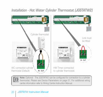
Note: Optional - The JGSTATW2 can be configured for connection to a cylinderthermostat. Please see Device Parameters on page 57. For additional wiringcentre information refer to Wiring Centre Instruction Manual.
WC connected cylinderthermostat (Default)
20 JGSTATW Instruction Manual
Installation - Hot Water Cylinder Thermostat (JGSTATW2)
ZONE 1
SL N L SL N L SL N L SL N L SL N L SL N L SL N LSL N L
ZONE 2 ZONE 3 ZONE 4 ZONE 5 ZONE 6 ZONE 7 ZONE 8
5 x 20mm
5 x 20mm
IN OUT
Cylinder thermostat
ZONE 1
SL N L SL N L SL N L SL N L SL N L SL N L SL N LSL N L
ZONE 2 ZONE 3 ZONE 4 ZONE 5 ZONE 6 ZONE 7 ZONE 8
5 x 20mm
5 x 20mm
IN OUT
Link must be fitted
HW Timer connectedto cylinder thermostat.
21www.speedfitUFH.co.uk
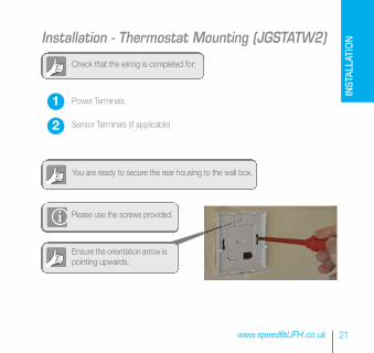
Check that the wiring is completed for:
Please use the screws provided.
Ensure the orientation arrow ispointing upwards.
You are ready to secure the rear housing to the wall box.
Power Terminals
Sensor Terminals (if applicable)
Installation - Thermostat Mounting (JGSTATW2)
1
2
INSTALLATION
22 JGSTATW Instruction Manual
Installation - Thermostat Mounting (JGSTATW2)
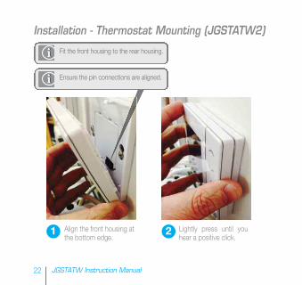
Fit the front housing to the rear housing.
Align the front housing atthe bottom edge.
Lightly press until youhear a positive click.
1 2
Ensure the pin connections are aligned.

23www.speedfitUFH.co.uk
Installation - LCD GraphicsICON FUNCTION
Box: Indicates selected mode e.g. means the current setpoint is Hi temp, means the Hi temp is not selected.
Sunny: High comfortable temperature.
Cloudy: Middle comfortable temperature.
Moon: Low comfortable temperature.
Programmable Thermostat program mode indicator: Indicates program is running, Auto On or Auto Off. For group thermostat this indicates that it is a member of a group.
Party indicator: When Party mode is active.
Holiday indicator: When Holiday mode is active
Frost protection indicator: Frost protection is active, not available in cooling mode (if applicable)
RF Transmission is active
Group 1 Control Thermostat
Group 2 Control Thermostat
Group 1 Thermostat
Group 2 Thermostat
INSTALLATION
ICON FUNCTION
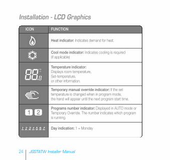
Heat indicator: Indicates demand for heat.
Cool mode indicator: Indicates cooling is required (if applicable)
Temperature indicator:Displays room temperature,Set-temperature,or other information.
Temporary manual override indicator: If the set temperature is changed when in program mode, the hand will appear until the next program start time.
Programs number indicator: Displayed in AUTO mode or Temporary Override. The number indicates which program is running.
Day indication: 1 = Monday
24 JGSTATW Installer Manual
Installation - LCD Graphics
25www.speedfitUFH.co.uk
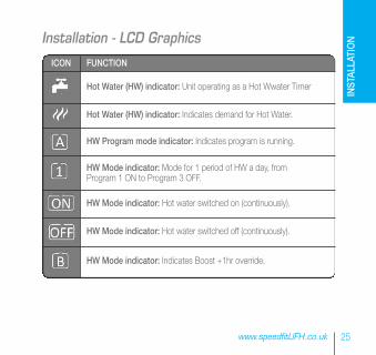
Installation - LCD Graphics
ICON FUNCTION
Hot Water (HW) indicator: Unit operating as a Hot Wwater Timer
Hot Water (HW) indicator: Indicates demand for Hot Water.
HW Program mode indicator: Indicates program is running.
HW Mode indicator: Mode for 1 period of HW a day, from Program 1 ON to Program 3 OFF.
HW Mode indicator: Hot water switched on (continuously).
HW Mode indicator: Hot water switched off (continuously).
HW Mode indicator: Indicates Boost +1hr override.
INSTALLATION
26 JGSTATW Instruction Manual
Installation - LCD Graphics
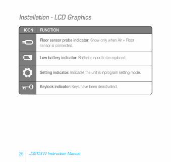
ICON FUNCTION
Floor sensor probe indicator: Show only when Air + Floor sensor is connected.
Low battery indicator: Batteries need to be replaced.
Setting indicator: Indicates the unit is inprogram setting mode.
Keylock indicator: Keys have been deactivated.
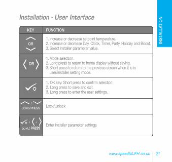
KEY FUNCTION
1. Increase or decrease setpoint temperature.2. Increase or decrease Day, Clock, Timer, Party, Holiday and Boost.3. Select installer parameter value.
1.Mode selection.2. Long press to return to home display without saving.3. Short press to return to the previous screen when it is in
user/installer setting mode.
1. OK key: Short press to confirm selection.2. Long press to save and exit.3. Long press to enter the user settings.
Lock/Unlock
Enter Installer parameter settings
OR
+
+ +
LONG PRESS
LONG PRESS
OR
27www.speedfitUFH.co.uk
Installation - User Interface
INSTALLATION
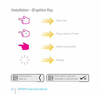
Press once
Press x amount of times
Hold for five seconds
Flashing
xx
Short press to save andlong press to save and exit
Short press toback up
28 JGSTATW Instruction Manual
Installation - Graphics Key

29www.speedfitUFH.co.uk
Installation - First Power Up
INSTALLATION
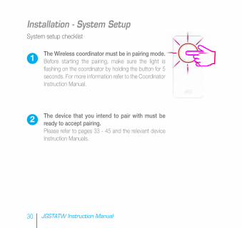
System setup checklist
The Wireless coordinator must be in pairing mode.Before starting the pairing, make sure the light isflashing on the coordinator by holding the button for 5seconds. For more information refer to the CoordinatorInstruction Manual.
The device that you intend to pair with must beready to accept pairing.Please refer to pages 33 - 45 and the relevant deviceInstruction Manuals.
30 JGSTATW Instruction Manual
Installation - System Setup
1
2
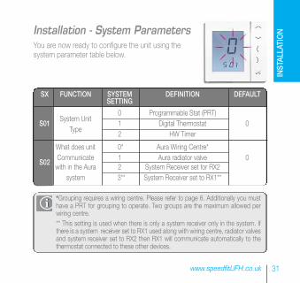
You are now ready to configure the unit using thesystem parameter table below.
*Grouping requires a wiring centre. Please refer to page 6. Additionally you musthave a PRT for grouping to operate. Two groups are the maximum allowed perwiring centre.** This setting is used when there is only a system receiver only in the system. Ifthere is a system receiver set to RX1 used along with wiring centre, radiator valvesand system receiver set to RX2 then RX1 will communicate automatically to thethermostat connected to these other devices.
31www.speedfitUFH.co.uk
Installation - System Parameters
SX FUNCTION SYSTEM DEFINITION DEFAULTSETTING
System Unit0 Programmable Stat (PRT)
S01Type
1 Digital Thermostat 02 HW Timer
What does unit 0* Aura Wiring Centre*
S02Communicate 1 Aura radiator valve 0with in the Aura 2 System Receiver set for RX2
system 3** System Receiver set to RX1**
INSTALLATION
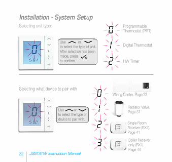
Selecting unit type.
Selecting what device to pair with
Use orto select the type of unit.After selection has beenmade, pressto confirm.
Use orto select the type ofdevice to pair with.
Programmable Thermostat (PRT)
Digital Thermostat
HW Timer
Wiring Centre. Page 33
Radiator Valve.Page 37
Single RoomReceiver (RX2).Page 41
Boiler Receiveronly (RX1). Page 44
32 JGSTATW Instruction Manual
Installation - System Setup
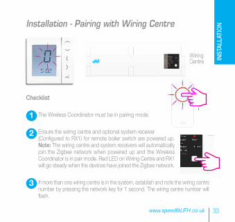
Wiring Centre
Checklist
The Wireless Coordinator must be in pairing mode.
Ensure the wiring centre and optional system receiver (Configured to RX1) for remote boiler switch are powered up.Note: The wiring centre and system receivers will automaticallyjoin the Zigbee network when powered up and the WirelessCoordinator is in pair mode. Red LED on Wiring Centre and RX1will go steady when the devices have joined the Zigbee network.
If more than one wiring centre is in the system, establish and note the wiring centrenumber by pressing the network key for 1 second. The wiring centre number willflash.
33www.speedfitUFH.co.uk
1
2
3
Installation - Pairing with Wiring Centre
INSTALLATION
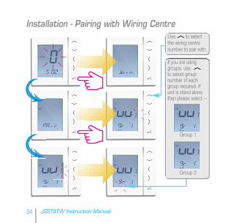
Use to selectthe wiring centrenumber to pair with.
34 JGSTATW Instruction Manual
Installation - Pairing with Wiring Centre
If you are usinggroups, useto select groupnumber of eachgroup required. Ifunit is stand alonethen please select --
Group 1
Group 2
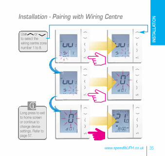
Long press to exitto home screenor continue tochange devicesettings. Refer topage 57.
Use orto select thewiring centre zonenumber 1 to 8.
35www.speedfitUFH.co.uk
Installation - Pairing with Wiring Centre
INSTALLATION
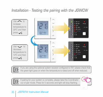
Use toincreasetemperature to30ºC and thenpress
Use todecreasetemperature to10ºC and thenpress
If you are using the optional system receiver configured to RX1 please check thatthe green light goes on when the temperature is raised and off when reduced.
If pairing for your system is complete, please take the Coordinatorout of pair mode. Press for 5 seconds and light will stop flashing.
36 JGSTATW Instruction Manual
Installation - Testing the pairing with the JGWCW
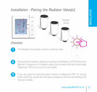
RadiatorValves
Checklist
The Wireless Coordinator must be in pairing mode.
Ensure that the radiator valves are in pairing mode (Refer to JGTRV InstructionManual). A maximum of 3 radiator valves can be paired with each thermostat.Please pair TRV’s on a room by room basis.
If you are using the optional system receiver configured to RX1 for remoteboiler switching, ensure this has been powered up and the red flashing LEDhas gone steady.
37www.speedfitUFH.co.uk
1
2
3
Installation - Pairing the Radiator Valve(s)
INSTALLATION
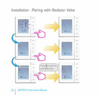
Press to start thepairing process.
38 JGSTATW Instruction Manual
Installation - Pairing with Radiator Valve
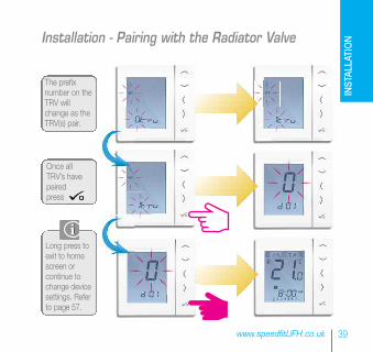
Long press toexit to homescreen orcontinue tochange devicesettings. Referto page 57.
Once allTRV’s havepairedpress
The prefixnumber on theTRV willchange as theTRV(s) pair.
39www.speedfitUFH.co.uk
Installation - Pairing with the Radiator Valve
INSTALLATION
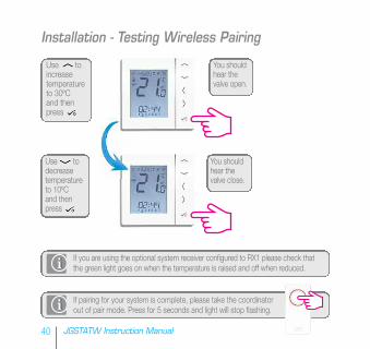
Use toincreasetemperatureto 30ºC and thenpress
Use todecreasetemperature to 10ºC and then press
If you are using the optional system receiver configured to RX1 please check thatthe green light goes on when the temperature is raised and off when reduced.
If pairing for your system is complete, please take the coordinatorout of pair mode. Press for 5 seconds and light will stop flashing.
40 JGSTATW Instruction Manual
Installation - Testing Wireless Pairing
You shouldhear thevalve open.
You shouldhear thevalve close.

JGBRConfiguredas RX2singleroomreceiver.
Checklist
The Coordinator must be in pairing mode.
The JGBR (set to RX2) is powered up and the red LED issteady. Refer to JGSTATW Instruction Manual.
If you are using the optional JGBR configured to RX1 for remote boilerswitching, ensure this has been powered up and the red flashing LED hasgone steady. Refer to JGBR Instruction Manual.
Refer to JGBRInstruction Manual.
41www.speedfitUFH.co.uk
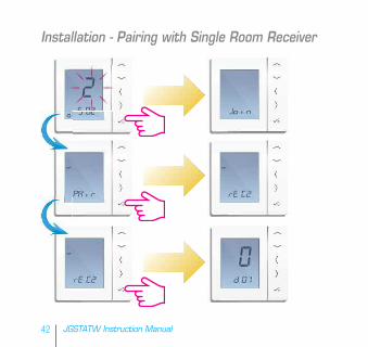
Installation - Pairing with Single Room Receiver
1
2
3
INSTALLATION
42 JGSTATW Instruction Manual
Installation - Pairing with Single Room Receiver
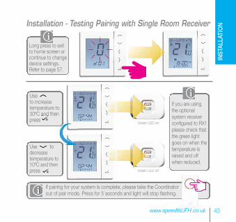
Long press to exitto home screen orcontinue to changedevice settings.Refer to page 57.
Useto increasetemperature to30ºC and thenpress
Green LED on
Green LED off
Use todecreasetemperature to10ºC and thenpress
If you are usingthe optionalsystem receiverconfigured to RX1please check thatthe green lightgoes on when thetemperature israised and offwhen reduced.
If pairing for your system is complete, please take the Coordinatorout of pair mode. Press for 5 seconds and light will stop flashing.
43www.speedfitUFH.co.uk
Installation - Testing Pairing with Single Room Receiver
INSTALLATION
Checklist
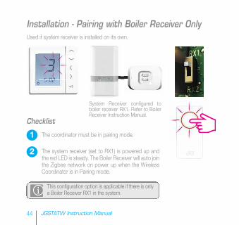
The coordinator must be in pairing mode.
The system receiver (set to RX1) is powered up andthe red LED is steady. The Boiler Receiver will auto jointhe Zigbee network on power up when the WirelessCoordinator is in Pairing mode.
System Receiver configured toboiler receiver RX1. Refer to BoilerReceiver Instruction Manual.
This configuration option is applicable if there is onlya Boiler Receiver RX1 in the system.
Used if system receiver is installed on its own.
44 JGSTATW Instruction Manual
1
2
Installation - Pairing with Boiler Receiver Only
45www.speedfitUFH.co.uk
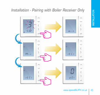
Installation - Pairing with Boiler Receiver Only
INSTALLATION
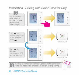
Long press to exit tohome screen orcontinue to changedevice settings.Refer to page 57.
Use toincrease temperatureto 30ºC and thenpress
Use todecreasetemperature to 10ºCand then press
Green LED on
Green LED off
If pairing for your system is complete, please take the coordinatorout of pair mode. Press for 5 seconds and light will stop flashing.
46 JGSTATW Instruction Manual
Installation - Pairing with Boiler Receiver Only
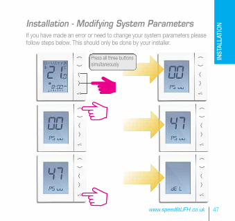
If you have made an error or need to change your system parameters pleasefollow steps below. This should only be done by your installer.
Press all three buttonssimultaneously
47www.speedfitUFH.co.uk
Installation - Modifying System Parameters
INSTALLATION
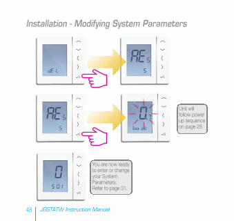
Unit willfollow powerup sequenceon page 29.
You are now readyto enter or changeyour SystemParameters.Refer to page 31.
48 JGSTATW Instruction Manual
Installation - Modifying System Parameters
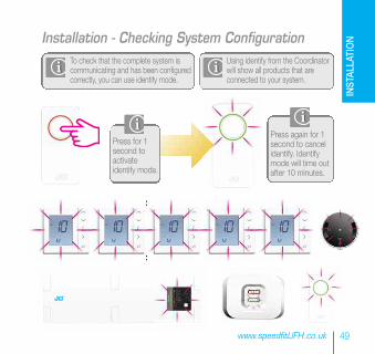
Press again for 1second to cancelidentify. Identifymode will time outafter 10 minutes.
To check that the complete system iscommunicating and has been configuredcorrectly, you can use identify mode.
Using identify from the Coordinatorwill show all products that areconnected to your system.
Press for 1second toactivateidentify mode.
49www.speedfitUFH.co.uk
Installation - Checking System Configuration
INSTALLATION
PRT
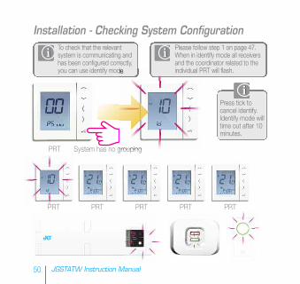
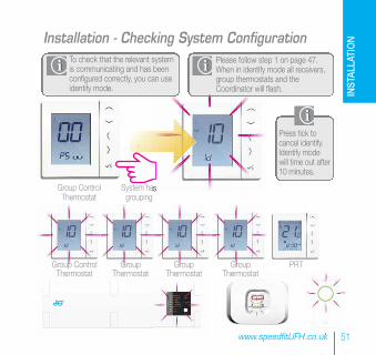
Press tick tocancel identify.Identify mode willtime out after 10minutes.
System has no grouping
To check that the relevantsystem is communicating andhas been configured correctly,you can use identify mode.
PRT PRT PRT PRT PRT
50 JGSTATW Instruction Manual
Installation - Checking System ConfigurationPlease follow step 1 on page 47.When in identify mode all receiversand the coordinator related to theindividual PRT will flash.
Group Control Thermostat
System has grouping
PRTGroup ControlThermostat
GroupThermostat
GroupThermostat
GroupThermostat
Press tick tocancel identify.Identify modewill time out after10 minutes.
To check that the relevant systemis communicating and has beenconfigured correctly, you can useidentify mode.
51www.speedfitUFH.co.uk
Installation - Checking System ConfigurationPlease follow step 1 on page 47.When in identify mode all receivers,group thermostats and theCoordinator will flash. IN
STALLATION
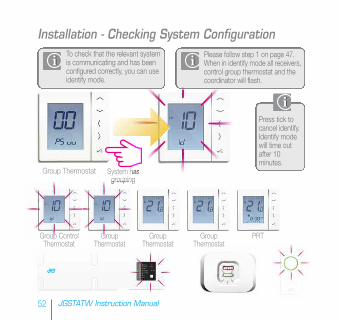
Group Thermostat System has grouping
PRTGroup Control Thermostat
Group Thermostat
Group Thermostat
Group Thermostat
Press tick tocancel identify.Identify modewill time outafter 10minutes.
To check that the relevant systemis communicating and has beenconfigured correctly, you can useidentify mode.
52 JGSTATW Instruction Manual
Installation - Checking System ConfigurationPlease follow step 1 on page 47.When in identify mode all receivers,control group thermostat and thecoordinator will flash.
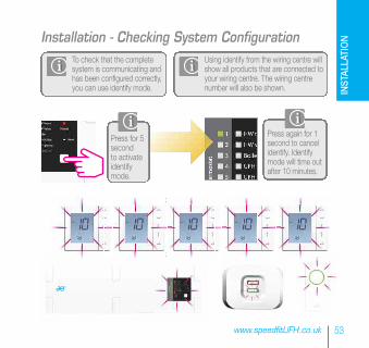
Press again for 1second to cancelidentify. Identifymode will time outafter 10 minutes.
To check that the completesystem is communicating andhas been configured correctly,you can use identify mode.
Using identify from the wiring centre willshow all products that are connected toyour wiring centre. The wiring centrenumber will also be shown.
Press for 5secondto activateidentifymode.
53www.speedfitUFH.co.uk
Installation - Checking System Configuration
INSTALLATION
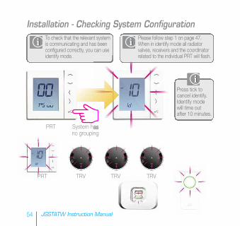
PRT
Press tick tocancel identify.Identify modewill time outafter 10 minutes.
System has no grouping
To check that the relevant systemis communicating and has beenconfigured correctly, you can useidentify mode.
TRV TRV TRV
54 JGSTATW Instruction Manual
Installation - Checking System ConfigurationPlease follow step 1 on page 47. When in identify mode all radiatorvalves, receivers and the coordinatorrelated to the individual PRT will flash.
PRT
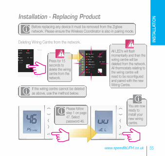
Deleting Wiring Centre from the network.
Press for 15seconds todelete the wiringcentre from thenetwork.
All LED’s will flashmomentarily and then thewiring centre will bedeleted from the network.All thermostats relating tothe wiring centre willneed to be reconfiguredand paired with the newWiring Centre.
If the wiring centre cannot be deletedas above, use the method below.
Please followstep 1 on page47. Selectpassword 46.
You are nowready toinstall yournew wiringcentre.
Before replacing any device it must be removed from the Zigbeenetwork. Please ensure the Wireless Coordinator is also in pairing mode.
55www.speedfitUFH.co.uk
Installation - Replacing Product
INSTALLATION
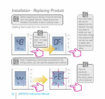
Before replacing any device it must be removedfrom the Zigbee network. Please ensure theWireless Coordinator is also in pairing mode.
Note: If replacing a thermostat connected to thewiring centre, you can use the replacement method.
Deleting thermostat from the network.
Your thermostatwill now bedeleted from thenetwork. You arenow ready toinstall your newthermostat. Pleasenote password 48can also be usedto delete otherdevices that areoffline.
Please followstep 1 on page47. Selectpassword 48.
The unitpreviouslyconnected tothe wiring centrewill be replaced.
56 JGSTATW Instruction Manual
Installation - Replacing Product
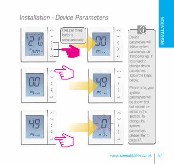
Deviceparameters willfollow systemparameters onfirst power up. Ifyou need tochange deviceparametersfollow the stepsbelow.
Please note, yoursystemparameters willbe shown firstbut cannot beedited in thissection. Tochange thesystemparametersplease refer topage 47.
Press all threebuttonssimultaneously
57www.speedfitUFH.co.uk
Installation - Device Parameters
INSTALLATION
58 JGSTATW Instruction Manual
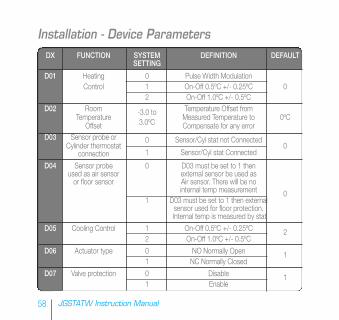
Installation - Device ParametersDX FUNCTION SYSTEM DEFINITION DEFAULT
SETTING
D01 Heating 0 Pulse Width ModulationControl 1 On-Off 0.5ºC +/- 0.25ºC 0
2 On-Off 1.0ºC +/- 0.5ºCD02 Room -3.0 to Temperature Offset from
Temperature3.0ºC
Measured Temperature to 0ºCOffset Compensate for any error
D03 Sensor probe or 0 Sensor/Cyl stat not ConnectedCylinder thermostat
1 Sensor/Cyl stat Connected0
connection
D04 Sensor probe 0 D03 must be set to 1 then used as air sensor external sensor be used asor floor sensor Air sensor. There will be no
internal temp measurement 01 D03 must be set to 1 then external
sensor used for floor protection.Internal temp is measured by stat
D05 Cooling Control 1 On-Off 0.5ºC +/- 0.25ºC 22 On-Off 1.0ºC +/- 0.5ºC
D06 Actuator type 0 NO Normally Open 11 NC Normally Closed
D07 Valve protection 0 Disable 11 Enable
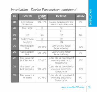
DX FUNCTION SYSTEM DEFINITION DEFAULTSETTING
D08 Frost Set point 5ºC - 17ºC Required Temperature for frost 5ºCTemperature protection and holiday mode
D09 Hour Format 0 12 11 24
D10 N/A N/A N/A N/A
D11 Daylight Saving 0 OFF 1Time (DST) 1 ON
D12 Heating Set point 5ºC - 35ºC Maximum temp that can 35ºCLimit be set for heating
D13 Cooling Set point 5ºC - 40ºC Maximum temp that can 5ºCLimit be set for Cooling
D14 Floor sensor High Output relay will be switched off Limit Temperature 6ºC -45ºC when temp is reached for 27ºC
floor protection
D15 Floor sensor Low Output relay will be switched on Limit Temperature 6ºC - 45ºC when temp is reached for 10ºC
floor protection
D16 Floor sensor Limit Output relay will be switched off for cooling 6ºC -45ºC when temp is reached for 6ºC
floor protection
59www.speedfitUFH.co.uk
Installation - Device Parameters continued
INSTALLATION
60 JGSTATW Instruction Manual
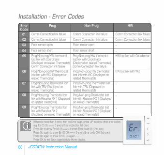
Installation - Error CodesError Prog Non-Prog HWCode010203
0405
06
07
08
09
Comm Connection link failure
Comm Connection link failure
Prog/Non-prog/HW thermostatlost link with Coordinator(Displayed on related Thermostat)Comm Connection link failure
Prog/Non-prog/HW thermostatlost link with Coordinator(Displayed on related Thermostat)Comm Connection link failure
Prog/Non-prog/HW thermostatlost link with WC (Displayed onrelated Thermostat)Prog/Non-prog Thermostat lostlink with TRV (Displayed onrelated Thermostat)
Prog/Non-prog Thermostat lostlink with Receiver RX 2(Displayed on related Thermostat)
Comm Connection link failure
Comm Connection link failure
Prog/Non-prog/HW thermostatlost link with WC (Displayed onrelated Thermostat)Prog/Non-prog Thermostat lostlink with TRV (Displayed onrelated Thermostat)
Prog/Non-prog Thermostat lostlink with Receiver RX 2 (Displayedon related Thermostat)
Comm Connection link failure
Comm Connection link failureFloor sensor open Floor sensor open -Floor sensor short Floor sensor short -
HW lost link with Coordinator
HW lost link with WC
-
Prog/Non-prog Thermostat lostlink with Receiver RX 1 (Displayedon related Thermostat)
Prog/Non-prog Thermostat lostlink with Receiver RX 1 (Displayedon related Thermostat)
-
-
If there is more than 1 error, then on Error page, press UP to show other error codes.e.g. Err 03 05 ===> 3 errors Error code 05 ( 1st one )Press Up to show Err 03 08 ===> 3 errors Error code 08 ( 2nd one )Press Up again to show Err 03 09 ===> 3 errors Error code 09 ( 3rd one )Press Up again to show Err 03 05 again......Press OK to exit Error page back to Home display.
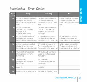
Error Prog Non-Prog HWCode10
11-18
19
20
21
22
23
24
61www.speedfitUFH.co.uk
Installation - Error Codes
WC lost link with hot water timer(Displayed on all relevantthermostats and also hot watertimer)
WC lost link with zone11=Zone 1, 12=Zone 2 etcDisplayed on allconnected thermostats
WC lost link with coordinator(Displayed on all connected thermostats and hot water timer)
WC lost link with receiver RX1(Displayed on all connectedthermostats and hot water timer)
TRV lost link with coordinator(Displayed on all connectedthermostats)
TRV low battery(Displayed on all connected thermostats)
Invalid TRV
Unit is rejected by wiring centre
Comm Connection link failure(Displayed on all relevant thermostats and also hot watertimer)
Comm Connection link failure11=Zone 1, 12=Zone 2 etcDisplayed on all connectedthermostats
WC lost link with coordinator(Displayed on all connectedthermostats and hot water timer)
WC lost link with receiver RX1(Displayed on all connectedthermostats and hot water timer)
TRV lost link with coordinator(Displayed on all connectedthermostats)
TRV low battery(Displayed on all connectedthermostats)
Invalid TRV
Unit is rejected by wiring centre
Comm Connection link failure(Displayed on all relevant thermostats and also hot watertimer)
-
WC lost link with coordinator(Displayed on all connectedthermostats and hot water timer)
WC lost link with receiver RX1(Displayed on all connectedthermostats and hot water timer)
-
-
-
-
INSTALLATION
62 JGSTATW Instruction Manual
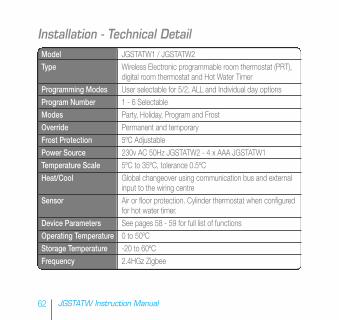
Installation - Technical DetailModel JGSTATW1 / JGSTATW2Type Wireless Electronic programmable room thermostat (PRT),
digital room thermostat and Hot Water TimerProgramming Modes User selectable for 5/2, ALL and Individual day optionsProgram Number 1 - 6 SelectableModes Party, Holiday, Program and FrostOverride Permanent and temporaryFrost Protection 5ºC AdjustablePower Source 230v AC 50Hz JGSTATW2 - 4 x AAA JGSTATW1Temperature Scale 5ºC to 35ºC, tolerance 0.5ºCHeat/Cool Global changeover using communication bus and external
input to the wiring centreSensor Air or floor protection. Cylinder thermostat when configured
for hot water timer.Device Parameters See pages 58 - 59 for full list of functionsOperating Temperature 0 to 50ºCStorage Temperature -20 to 60ºCFrequency 2.4HGz Zigbee
PRT and Group Control Thermostat.
63www.speedfitUFH.co.uk
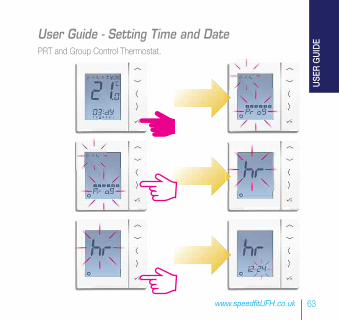
User Guide - Setting Time and Date
USER GUIDE
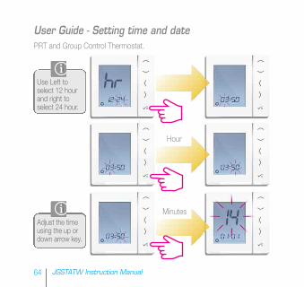
Use Left toselect 12 hourand right toselect 24 hour.
Adjust the timeusing the up ordown arrow key.
PRT and Group Control Thermostat.
Hour
Minutes
64 JGSTATW Instruction Manual
User Guide - Setting time and date
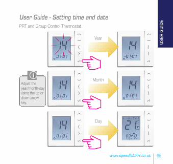
PRT and Group Control Thermostat.
Month
Year
Day
Adjust theyear/month/dayusing the up ordown arrowkey.
65www.speedfitUFH.co.uk
User Guide - Setting time and date
USER GUIDE
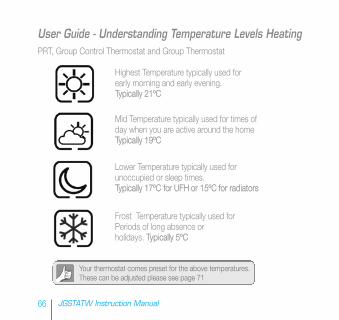
Highest Temperature typically used for early morning and early evening. Typically 21ºC
Mid Temperature typically used for times of day when you are active around the home Typically 19ºC
Lower Temperature typically used for unoccupied or sleep times. Typically 17ºC for UFH or 15ºC for radiators
Frost Temperature typically used for Periods of long absence or holidays. Typically 5ºC
Your thermostat comes preset for the above temperatures. These can be adjusted please see page 71
PRT, Group Control Thermostat and Group Thermostat
66 JGSTATW Instruction Manual
User Guide - Understanding Temperature Levels Heating
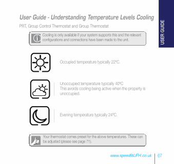
Occupied temperature typically 22ºC.
Unoccupied temperature typically 40ºCThis avoids cooling being active when the property isunoccupied.
Evening temperature typically 24ºC.
Your thermostat comes preset for the above temperatures. These canbe adjusted (please see page 71).
Cooling is only available if your system supports this and the relevantconfigurations and connections have been made to the unit.
PRT, Group Control Thermostat and Group Thermostat
67www.speedfitUFH.co.uk
User Guide - Understanding Temperature Levels Cooling
USER GUIDE
12.00 7.00 9.00 17.00 23.00
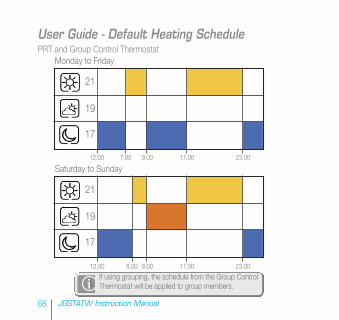
Monday to Friday
12.00 8.00 9.00 17.00 23.00
Saturday to Sunday
PRT and Group Control Thermostat
If using grouping, the schedule from the Group ControlThermostat will be applied to group members.
68 JGSTATW Instruction Manual
User Guide - Default Heating Schedule
21
19
17
21
19
17
22
40
24
12.00 7.00 9.00 17.00 23.00
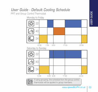
Monday to Friday
12.00 8.00 9.00 17.00 23.00
Saturday to Sunday
PRT and Group Control Thermostat
If using grouping, the schedule from the group controlthermostat will be applied to group members.
69www.speedfitUFH.co.uk
User Guide - Default Cooling Schedule
22
40
24
USER GUIDE
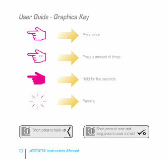
Press once
Press x amount of times
Hold for five seconds
Flashing
xx
Short press to save andlong press to save and exit
Short press to back up
70 JGSTATW Instruction Manual
User Guide - Graphics Key
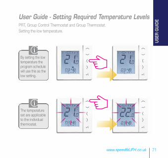
By setting the lowtemperature theprogram schedulewill use this as thelow setting.
The temperatureset are applicableto the individualthermostat.
PRT, Group Control Thermostat and Group Thermostat. Setting the low temperature.
71www.speedfitUFH.co.uk
User Guide - Setting Required Temperature Levels
USER GUIDE
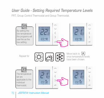
Repeat forMove back toonce temperature levelshave been chosen.
By setting thelow temperaturethe programs willuse this as thelow setting.
The temperatureset areapplicable to theindividualthermostat.
PRT, Group Control Thermostat and Group Thermostat.
72 JGSTATW Instruction Manual
User Guide - Setting Required Temperature Levels
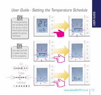
Use right and leftto select the dayof the programs.
5/2
7 Days
Individual
If using grouping,the schedule fromthe group controlthermostat will beapplied to groupmembers.
73www.speedfitUFH.co.uk
User Guide - Setting the Temperature Schedule
USER GUIDE
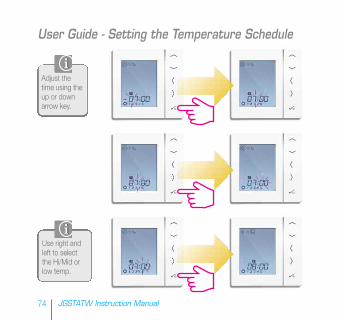
Adjust thetime using theup or downarrow key.
Use right andleft to selectthe Hi/Mid orlow temp.
74 JGSTATW Instruction Manual
User Guide - Setting the Temperature Schedule
When you set the temperature the schedule will respond to
those temperatures see page 71 on how to change
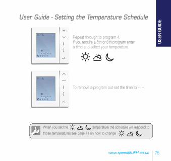
Repeat through to program 4.If you require a 5th or 6th program entera time and select your temperature.
To remove a program out set the time to --:--.
75www.speedfitUFH.co.uk
User Guide - Setting the Temperature Schedule
USER GUIDE
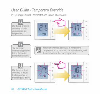
Use the up or downarrow key to viewyour program settemperature.
The temporaryoverride is applicableto the thermostatbeing changed only.
Use the up or downarrow key to adjustthe temperature tothe setting you desire.
Temporary override allows you to increase thetemperature or decrease it to the desired setting untilit reverts back on the next program time.
PRT, Group Control Thermostat and Group Thermostat.
76 JGSTATW Instruction Manual
User Guide - Temporary Override
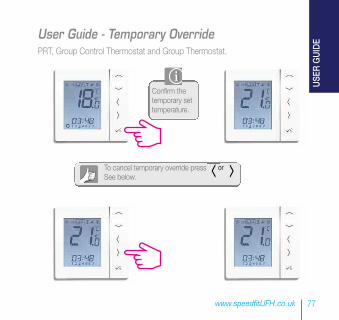
To cancel temporary override press orSee below.
PRT, Group Control Thermostat and Group Thermostat.
Confirm thetemporary settemperature.
77www.speedfitUFH.co.uk
User Guide - Temporary Override
USER GUIDE
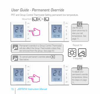
To cancel permanent override selectSee below.
Permanent override in a Group Control Thermostatwill also affect the Group Thermostats unless theyare removed from the group. See page 82.
Move from to
Use the up ordown arrow key toview your settemperature. Seepage 71.
To adjust yourpermanent overridetemperature, followthe steps on page71.
Repeat for
if required
PRT and Group Control Thermostat Setting permanent low temperature.
78 JGSTATW Instruction Manual
User Guide - Permanent Override
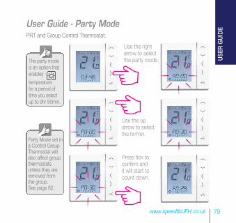
The party modeis an option thatenables
temperaturefor a period oftime you selectup to 9hr 50min.
Use the rightarrow to selectthe party mode.
Use the uparrow to selectthe hr/min.
Press tick toconfirm andit will start tocount down.
Party Mode set ina Control GroupThermostat willalso affect groupthermostatsunless they areremoved fromthe group. See page 82.
PRT and Group Control Thermostat.
79www.speedfitUFH.co.uk
User Guide - Party Mode
USER GUIDE
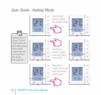
Use the rightarrow to selectthe holiday mode.
Use the uparrow to selecthow many daysto be off for.
Press tick toconfirm and it willstart the holidaycount down.
Holiday set in aGroup ControlThermostat willalso affect groupthermostatsunless they areremoved fromthe group. See page 82.
80 JGSTATW Instruction Manual
User Guide - Holiday Mode
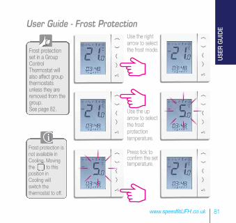
Use the rightarrow to selectthe frost mode.
Use the uparrow to selectthe frostprotectiontemperature.
Press tick toconfirm the settemperature.
Frost protectionset in a GroupControlThermostat willalso affect groupthermostatsunless they areremoved from thegroup. See page 82.
81www.speedfitUFH.co.uk
User Guide - Frost Protection
Frost protection isnot available inCooling. Movingthe to thisposition inCooling willswitch thethermostat to off.
USER GUIDE
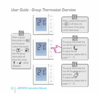
When a group thermostat isin it will follow themode status of the groupcontrol thermostat.
The group thermostat hasnow left the group and is inpermanentTo adjust the settemperature, please refer topages 71 - 72.
The group thermostat hasnow left the group and is inpermanentTo adjust the settemperature, please refer topages 71 - 72.
When a groupthermostat is inand the groupcontrol thermostat is in or then the group thermostat willfollow this mode.
or will bedisplayed.
82 JGSTATW Instruction Manual
User Guide - Group Thermostat Overview
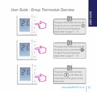
The group thermostat has now leftthe group and is in permanentTo adjust the set temperature, please refer to page 71 - 72.
The group thermostat has now leftthe group and is in permanentTo adjust the set temperature, please refer to page 71 - 72.
The group thermostat has beenreturned to it will follow the mode status of the group control thermostat.
83www.speedfitUFH.co.uk
User Guide - Group Thermostat Overview
USER GUIDE
2
3
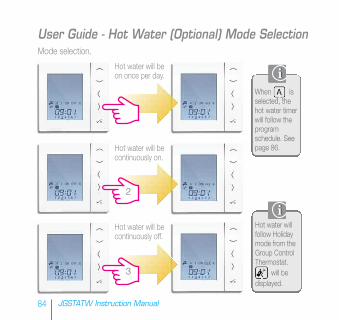
Mode selection.
Hot water willfollow Holidaymode from theGroup ControlThermostat.
will bedisplayed.
When isselected, thehot water timerwill follow theprogramschedule. Seepage 86.
Hot water will beon once per day.
Hot water will becontinuously on.
Hot water will becontinuously off.
84 JGSTATW Instruction Manual
User Guide - Hot Water (Optional) Mode Selection
85www.speedfitUFH.co.uk
User Guide - Hot Water Boost
USER GUIDE
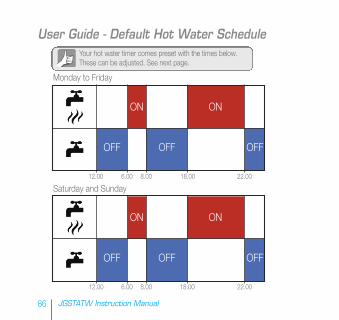
12.00 6.00 8.00 18.00 22.00
ON ON
OFFOFF OFF
12.00 6.00 8.00 18.00 22.00
Saturday and Sunday
Monday to Friday
ON ON
OFFOFF OFF
Your hot water timer comes preset with the times below.These can be adjusted. See next page.
86 JGSTATW Instruction Manual
User Guide - Default Hot Water Schedule
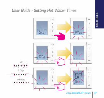
5/2
7 Days
Individual
87www.speedfitUFH.co.uk
User Guide - Setting Hot Water Times
USER GUIDE
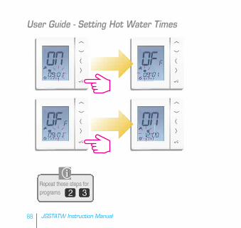
88 JGSTATW Instruction Manual
User Guide - Setting Hot Water Times
Repeat these steps forprograms
Repeat these steps forprograms
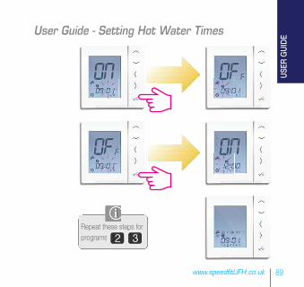
89www.speedfitUFH.co.uk
User Guide - Setting Hot Water Times
USER GUIDE
90 JGSTATW Instruction Manual
Installer Notes
91www.speedfitUFH.co.uk
Installer Notes
DisclaimerCustomers that choose to operate their heating remotely using JG Aura Range technology via their
personal computer, tablet or smart phone device(s) will be entering into a contract with Salus Controls
plc (“Salus”), which is a third party supplier of the software. John Guest Ltd and affiliates within the
John Guest group of companies from time to time (the “John Guest Group”) make no representations
or warranties of any kind about the reliability or suitability of the software or applications provided by
Salus. The John Guest Group disclaims liability (excluding liability for death and personal injury
resulting from negligence) for any loss or damage caused by the software provided to customers by
Salus. Any agreement entered into with Salus is therefore strictly at your own risk.

John Guest Speedfit LimitedHorton Road, West Drayton, Middlesex UB7 8JL, England.
Tel: 01895 449233 Fax: 01895 420321www.speedfitUFH.co.ukTechnical Help Desk: 01895 425333
,
The above namestyles are all trademarks of John Guest International Limited.
© John Guest International Limited 2014. All rights reserved.
Z2105/425/1114
and