Embed Size (px)
Citation preview

16
1
SEPED303003EN
Installation Base unitConnection
1 Base unit.
2 8 fixing points for 4 spring clips.
3 Red LED: Sepam unavailable.
4 Green LED: Sepam on.
5 Gasket.
20-pin connector for:
b 24 V DC to 250 V DC auxiliary supply
b 5 relay outputs.
Connector for 3 phase current I1, I2, I3 inputs.
b Sepam T87, M87, M88, G87, G88:
connector for 3 phase current I'1, I'2, I'3 inputs
b Sepam B83: connector for
v 3 phase voltage V'1, V'2, V'3 inputs
v 1 residual voltage V’0 input.
b Sepam C86: connector for capacitor unbalance
current inputs.
Communication port 1.
Communication port 2.
Remote module connection port 1.
Remote module connection port 2.
20-pin connector for:
b 3 phase voltage V1, V2, V3 inputs
b 1 residual voltage V0 input.
b 2 residual current I0, I'0 inputs.
Communication port 3 for ACE850 communication
interfaces only.
Connector for 1st MES120 input/output module.
Connector for 2nd MES120 input/output module.
Connector for 3rd MES120 input/output module.
Rear panel description
DE
51
78
1
Functional earth.
Connection characteristicsConnector Type Reference Wiring
, Screw-type CCA620 b Wiring without fittings:v 1 wire with max. cross-section 0.5 to 2.5 mm² (u AWG 20-12) or 2 wires with max. cross-section 0.5 to 1 mm² (u AWG 20-16)v Stripped length: 8 to 10 mm (0.31 to 0.39 in)b Wiring with fittings:v Recommended wiring with Schneider Electric fitting:- DZ5CE015D for 1 wire 1.5 mm² (AWG 16)- DZ5CE025D for 1 wire 2.5 mm² (AWG 12)- AZ5DE010D for 2 wires 1 mm² (AWG 18)v Tube length: 8.2 mm (0.32 in)v Stripped length: 8 mm (0.31 in)
6.35 mm (0.25 in) ring lugs CCA622 b 6.35 mm ring or spade lugs (0.25 in) (1/4")b Wire with max. cross-section 0.2 to 2.5 mm² (u AWG 24-12)b Stripped length: 6 mm (0.23 in)b Use an appropriate tool to crimp the lugs on the wiresb Maximum of 2 ring or spade lugs per terminalb Tightening torque: 0.7 to 1 Nm (8.85 lb-in)
, 4 mm (0.15 in) ring lugs CCA630 or CCA634, for connection of 1 A or 5 A CTs
b Wire with cross-section 1.5 to 6 mm² (AWG 16-10)b Stripped length: 6 mm (0.23 in)b Use an appropriate tool to crimp the lugs on the wiresb Tightening torque: 1.2 N.m (11 lb-in)
RJ45 connector CCA671, for connection of 3 LPCT sensors
Integrated with LPCT sensor
, White RJ45 connector CCA612
, Black RJ45 connector CCA770: L = 0.6 m (2 ft)CCA772: L = 2 m (6.6 ft)CCA774: L = 4 m (13.1 ft)CCA785 for MCS025 module: L = 2 m (6.6 ft)
Blue RJ45 connector CCA614
DE
51
84
5
Functional earth
Ring lug Earthing braid, to be connected to cubicle groundingb Flat copper braid with cross-section u 9 mm² (> AWG 8)b Maximum length:500 mm (19.68 in)
A
B1
B2
C1
C2
D1
D2
E
F
H1
H2
H3
t
A E
B1 B2
C1 C2
D1 D2
F
17
1
SEPED303003EN
Installation Base unitConnection
D
E5
18
93
Note: See connection characteristics page 16
NOTICE DANGERLOSS OF PROTECTION OR RISK OF
NUISANCE TRIPPING
If the Sepam is no longer supplied with power or
is in fail-safe position, the protection functions are
no longer active and all the Sepam output relays
are dropped out. Check that this operating mode
and the watchdog relay wiring are compatible
with your installation.
Failure to follow these instructions can result
in equipment damage and unwanted
shutdown of the electrical installation.
HAZARD OF ELECTRIC SHOCK, ELECTRIC ARC OR BURNS
Only qualified personnel should install this equipment. Such work should be
performed only after reading this entire set of instructions.
NEVER work alone.
Turn off all power supplying this equipment before working on or inside it.
Consider all sources of power, including the possibility of backfeeding.
Always use a properly rated voltage sensing device to confirm that all power
is off.
Start by connecting the device to the protective earth and to the functional
earth.
Screw tight all terminals, even those not in use.
Failure to follow these instructions will result in death or serious injury.
NOTICERISK OF DESTRUCTION OF THE SEPAM
Do not invert the connectors and .
Failure to follow these instructions can result
in equipment damage.
A E

18
1
SEPED303003EN
Installation Base unitConnection of Sepam B83
DE
80
99
3
Connector Type Reference Wiring4 mm (0.15 in) ring lugs CCA630 or CCA634, for connection
of 1 A or 5 A CTsb wire with cross-section 1.5 to 6 mm² (AWG 16-10)b stripped length: 6 mm (0.236 in)b use an appropriate tool to crimp the lugs on the wiresb tightening torque: 1.2 N.m (11 lb-in)
Screw type CCT640 b VT wiring: identical to the CCA620 wiringb Earthing connection: by 4 mm (0.16 in) ring lugb tightening torque: 1.2 N.m (11 lb-in)
DE
51
84
5
Functional earth
Ring lug Earthing braid, to be connected to cubicle grounding:b flat copper braid with cross-section u 9 mm² (> AWG 8)b maximum length: 500 mm (19.68 in)
Connection characteristics of connectors , , , , , : see page 14
NOTICE DANGERLOSS OF PROTECTION OR RISK OF NUISANCE TRIPPINGIf the Sepam is no longer supplied with power or
is in fail-safe position, the protection functions are
no longer active and all the Sepam output relays
are dropped out. Check that this operating mode
and the watchdog relay wiring are compatible
with your installation.
Failure to follow these instructions can result in equipment damage and unwanted shutdown of the electrical installation.
HAZARD OF ELECTRIC SHOCK, ELECTRIC ARC OR BURNSb Only qualified personnel should install this equipment. Such work should be
performed only after reading this entire set of instructions.
b NEVER work alone.
b Turn off all power supplying this equipment before working on or inside it.
Consider all sources of power, including the possibility of backfeeding.
b Always use a properly rated voltage sensing device to confirm that all power
is off.
b Start by connecting the device to the protective earth and to the functional
earth.
b Screw tight all terminals, even those not in use.
Failure to follow these instructions will result in death or serious injury.
NOTICERISK OF DESTRUCTION OF THE SEPAM
Do not invert the connectors and .
Failure to follow these instructions can result in equipment damage.
CCT640
CCA630
B1
B2
A E C1 C2 D1 D2
A E

19
1
SEPED303003EN
Installation Base unitConnection of Sepam C86
D
E8
04
61
Connector Type Reference Wiring4 mm (0.15 in) ring lugs CCA630 or CCA634, for
connection of 1 A or 5 A CTswire with cross-section 1.5 to 6 mm² (AWG 16-10)stripped length: 6 mm (0.236 in)use an appropriate tool to crimp the lugs on the wirestightening torque: 1.2 N.m (11 lb-in)
RJ45 connector CCA671, for connection of 3 LPCT sensors
Integrated with LPCT sensor
4 mm (0.15 in) ring lugs CCA630 or CCA634, for connection of 1 A, 2A or 5 A CTs
wire with cross-section 1.5 to 6 mm² (AWG 16-10)stripped length: 6 mm (0.236 in)use an appropriate tool to crimp the lugs on the wirestightening torque: 1.2 N.m (11 lb-in)
DE
51
84
5
Functional earth
Ring lugs Earthing braid, to be connected to cubicle grounding:flat copper braid with cross-section 9 mm² (>AWG 8)maximum length: 500 mm (19.68 in)
Connection characteristics of connectors , , , , , : see page 14
D D
B1
B2
A E C1 C2 D1 D2

20
1
SEPED303003EN
Installation Base unitConnection of phase current inputs
Variant 1: phase current measurement by 3 x 1 A or 5 A CTs (standard connection)
DE
80
08
9
DescriptionConnection of 3 x 1 A or 5 A sensors to the CCA630 or CCA634 connector.
The measurement of the 3 phase currents allows the calculation of residual current.
Parameters
Sensor type 5 A CT or 1 A CT
Number of CTs I1, I2, I3
Rated current (In) 1 A to A
Variant 2: phase current measurement by 2 x 1 A or 5 A CTs
DE
80
08
8
DescriptionConnection of 2 x 1 A or 5 A sensors to the CCA630 or CCA634 connector.
Measurement of phase 1 and 3 currents is sufficient for all protection functions based
on phase current.
The phase current I2 is only assessed for metering functions, assuming that I0 = 0.
This arrangement does not allow the calculation of residual current, nor use of
ANSI 87T and 87M differential protection functions on the Sepam T87, M87, M88,
G87 and G88.
Paramètres
Sensor type 5 A CT or 1 A CT
Number of CTs I1, I3
Rated current (In) 1 A to A
CCA630/
CCA634
CCA630/CCA634

21
1
SEPED303003EN
Installation Base unitConnection of phase current inputs
Variant 3: phase current measurement by 3 LPCT type sensors
DE
51
79
0
DescriptionConnection of 3 Low Power Current Transducer (LPCT) type sensors to the CCA671
connector. If only one or two sensors are connected, Sepam goes into fail-safe
position.
Measurement of the 3 phase currents allows the calculation of residual current.
It is not possible to use LPCT sensors for the following measurements:
b phase-current measurements for Sepam T87, M88 and G88 with ANSI 87T
transformer differential protection (connectors and )
b phase-current measurements for Sepam B83 (connector )
b unbalance-current measurements for Sepam C86 (connector ).
Parameters
Sensor type LPCT
Number of CTs I1, I2, I3
Rated current (In) 25, 50, 100, 125, 133, 200, 250, 320, 400, 500, 630, 666, 1000, 1600, 2000 or 3150 A
Note: Parameter In must be set twice:
b Software parameter setting using the advanced UMI or the SFT2841 software toolb Hardware parameter setting using microswitches on the CCA671 connector
B1 B2
B1
B2

22
1
SEPED303003EN
Installation Base unitConnection of resid ual current inputs
Variant 1: residual current calculation by sum of 3 phase currents
DE
80
08
9
Description
Residual current is calculated by the vector sum of the 3 phase currents I1, I2 and
I3, measured by 3 x 1 A or 5 A CTs or by 3 LPCT type sensors.
See current input connection diagrams.
Parameters
Residual current Rated residual current Measuring range
Sum of 3 Is In0 = In, CT primary current 0.01 to 40 In0 (minimum 0.1 A)
Variant 2: residual current measurement by CSH120 or CSH200 core balance CT (standard connection)
DE
80
08
3
Description
Arrangement recommended for the protection of isolated or compensated neutral
systems, in which very low fault currents need to be detected.
Parameters
Residual current Rated residual current Measuring range
2 A rating CSH In0 = 2 A 0.1 to 40 A
20 A rating CSH In0 = 20 A 0.2 to 400 A
Variant 3: residual current measurement by 1 A or 5 A CTs and CCA634
DE
80
08
6
Description
Residual current measurement by 1 A or 5 A CTs
b Terminal 7: 1 A CT
b Terminal 8: 5 A CT
Parameters
Residual current Rated residual current Measuring range
1 A CT In0 = In, CT primary current 0.01 to 20 In0 (minimum 0.1 A)
5 A CT In0 = In, CT primary current 0.01 to 20 In0 (minimum 0.1 A)
DE
80
08
7
CCA630/
CCA634
23
1
SEPED303003EN
Installation Base unitConnection of residual current inputs
Variant 4: residual current measurement by 1 A or 5 A CTs and CSH30 interposing ring CT
DE
80
13
0
DescriptionThe CSH30 interposing ring CT is used to connect 1 A or 5 A CTs to Sepam to
measure residual current:
b CSH30 interposing ring CT connected to 1 A CT: make 2 turns through CSH
primary
b CSH30 interposing ring CT connected to 5 A CT: make 4 turns through CSH
primary.
Parameters
Residual current Rated residual current Measuring range
1 A CT In0 = In, CT primary current 0.01 to 20 In0 (minimum 0.1 A)
5 A CT In0 = In, CT primary current 0.01 to 20 In0 (minimum 0.1 A)
DE
81
05
5
Variant 5: residual current measurement by core balance CT with ratio of 1/n (n between 50 and 1500)
DE
80
10
2
DescriptionThe ACE990 is used as an interface between a MV core balance CT with a ratio of
1/n (50 y n y 1500) and the Sepam residual current input.
This arrangement allows the continued use of existing core balance CTs on the
installation.
Parameters
Residual current Rated residual current Measuring range
ACE990 - range 1 In0 = Ik.n(1) 0.01 to 20 In0 (minimum 0.1 A)
(0.00578 y k y 0.04)
ACE990 - range 2 In0 = Ik.n(1) 0.01 to 20 In0 (minimum 0.1 A)
(0.0578 y k y 0.26316)
(1) n = number of core balance CT turnsk = factor to be determined according to ACE990 wiring and setting range used by Sepam
Variant 6: neutral point current measurement for the restricted earth protection (ANSI 64REF) and for a network where the neutral is not distributed
DE
80
98
4
Description
The residual current is measured by taking the sum of the 3 phase currents using the
CT whose secondary current is 1 A or 5 A.
The neutral point current is measured using the CT whose secondary current is 1 A
or 5 A:
b Terminal 7: 1 A CT
b Terminal 8: 5 A CT
Parameters
Secondary current Rated residual current Measuring range
1 A CT In0 = phase CT primary current In 0.01 to 20 In0 (0.1 A minimum)
5 A CT In0 = phase CT primary current In 0.01 to 20 In0 (0.1 A minimum)
1 A CT: 2 turns
5 A CT: 4 turns
1 A CT: 2 turns
5 A CT: 4 turns
24
1
SEPED303003EN
Installation Base unitConnection of low voltage residual current inputs
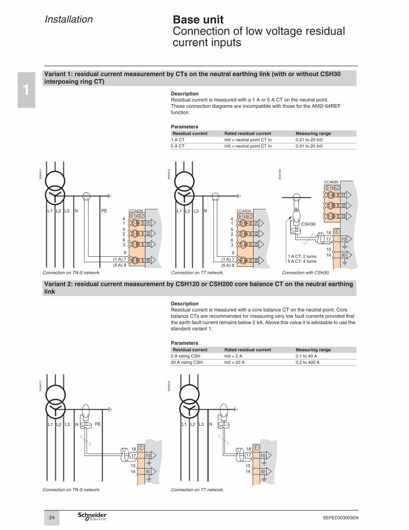
Variant 1: residual current measurement by CTs on the neutral earthing link (with or without CSH30 interposing ring CT)
DescriptionResidual current is measured with a 1 A or 5 A CT on the neutral point.
These connection diagrams are incompatible with those for the ANSI 64REF
function.
Parameters
Residual current Rated residual current Measuring range
1 A CT In0 = neutral point CT In 0.01 to 20 In0
5 A CT In0 = neutral point CT In 0.01 to 20 In0
DE
80
97
1
DE
80
97
2
DE
81
05
3
Connection on TN-S network. Connection on TT network. Connection with CSH30.
Variant 2: residual current measurement by CSH120 or CSH200 core balance CT on the neutral earthing link
DescriptionResidual current is measured with a core balance CT on the neutral point. Core
balance CTs are recommended for measuring very low fault currents provided that
the earth fault current remains below 2 kA. Above this value it is advisable to use the
standard variant 1.
Parameters
Residual current Rated residual current Measuring range
2 A rating CSH In0 = 2 A 0.1 to 40 A
20 A rating CSH In0 = 20 A 0.2 to 400 A
DE
80
97
4
DE
80
97
5
Connection on TN-S network. Connection on TT network.
N PE N
1 A CT: 2 turns
5 A CT: 4 turns
PEN N
25
1
SEPED303003EN
Installation Base unitConnection of low voltage residual current inputs
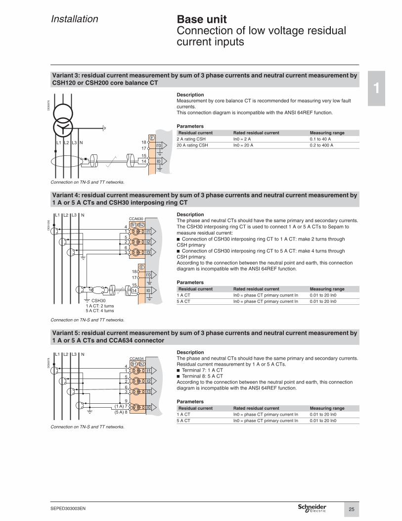
Variant 3: residual current measurement by sum of 3 phase currents and neutral current measurement by CSH120 or CSH200 core balance CT
DE
80
97
6
DescriptionMeasurement by core balance CT is recommended for measuring very low fault
currents.
This connection diagram is incompatible with the ANSI 64REF function.
Parameters
Residual current Rated residual current Measuring range
2 A rating CSH In0 = 2 A 0.1 to 40 A
20 A rating CSH In0 = 20 A 0.2 to 400 A
Connection on TN-S and TT networks.
Variant 4: residual current measurement by sum of 3 phase currents and neutral current measurement by 1 A or 5 A CTs and CSH30 interposing ring CT
DE
81
05
6
DescriptionThe phase and neutral CTs should have the same primary and secondary currents.
The CSH30 interposing ring CT is used to connect 1 A or 5 A CTs to Sepam to
measure residual current:
b Connection of CSH30 interposing ring CT to 1 A CT: make 2 turns through
CSH primary
b Connection of CSH30 interposing ring CT to 5 A CT: make 4 turns through
CSH primary.
According to the connection between the neutral point and earth, this connection
diagram is incompatible with the ANSI 64REF function.
Parameters
Residual current Rated residual current Measuring range
1 A CT In0 = phase CT primary current In 0.01 to 20 In0
5 A CT In0 = phase CT primary current In 0.01 to 20 In0
Connection on TN-S and TT networks.
Variant 5: residual current measurement by sum of 3 phase currents and neutral current measurement by 1 A or 5 A CTs and CCA634 connector
DE
80
97
8
DescriptionThe phase and neutral CTs should have the same primary and secondary currents.
Residual current measurement by 1 A or 5 A CTs.
b Terminal 7: 1 A CT
b Terminal 8: 5 A CT
According to the connection between the neutral point and earth, this connection
diagram is incompatible with the ANSI 64REF function.
Parameters
Residual current Rated residual current Measuring range
1 A CT In0 = phase CT primary current In 0.01 to 20 In0
5 A CT In0 = phase CT primary current In 0.01 to 20 In0
Connection on TN-S and TT networks.
N
N
1 A CT: 2 turns
5 A CT: 4 turns
N
26
1
SEPED303003EN
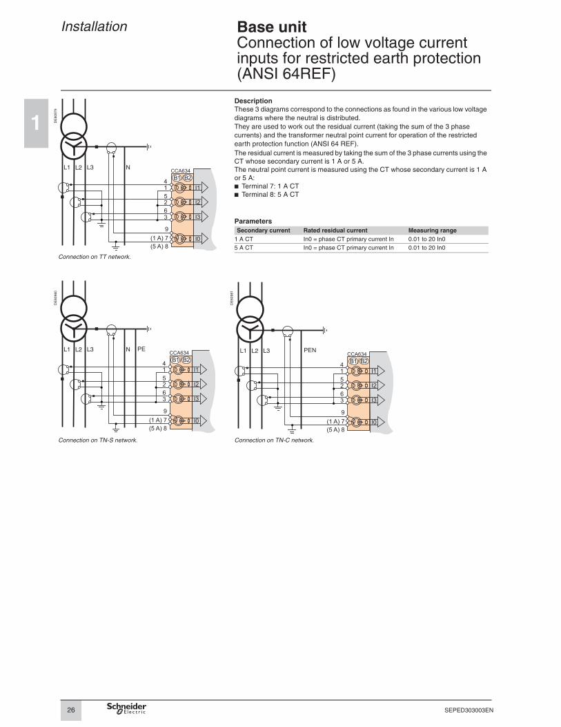
Installation Base unitConnection of low voltage current inputs for restricted earth protection (ANSI 64REF)
DE
80
97
9
DescriptionThese 3 diagrams correspond to the connections as found in the various low voltage
diagrams where the neutral is distributed.
They are used to work out the residual current (taking the sum of the 3 phase
currents) and the transformer neutral point current for operation of the restricted
earth protection function (ANSI 64 REF).
The residual current is measured by taking the sum of the 3 phase currents using the
CT whose secondary current is 1 A or 5 A.
The neutral point current is measured using the CT whose secondary current is 1 A
or 5 A:
b Terminal 7: 1 A CT
b Terminal 8: 5 A CT
Parameters
Secondary current Rated residual current Measuring range
1 A CT In0 = phase CT primary current In 0.01 to 20 In0
5 A CT In0 = phase CT primary current In 0.01 to 20 In0
Connection on TT network.
DE
80
98
0
DE
80
98
1
Connection on TN-S network. Connection on TN-C network.
N
N PE PEN

27
1
SEPED303003EN
Installation Base unitConnection of main voltage inputs
Phase voltage input connection variantsVariant 1: measurement of 3 phase-to-neutral voltages (3 V, standard connection)
Variant 2: measurement of 2 phase-to-phase voltages (2 U)
DE
51
79
5
DE
51
79
6
Measurement of the 3 phase-to-neutral voltages allows
the calculation of residual voltage, V0Σ.
This variant does not allow the calculation of residual voltage.
Variant 3: measurement of 1 phase-to-phase voltage (1 U)
Variant 4: measurement of 1 phase-to-neutral voltage (1 V)
DE
51
79
7
DE
51
79
8
This variant does not allow the calculation of residual
voltage.
This variant does not allow the calculation of residual voltage.
Residual voltage input connection variantsVariant 5: measurement of residual voltage V0
Variant 6: measurement of residual voltage Vnt in generator neutral point
DE
51
79
9
DE
51
80
0

28
1
SEPED303003EN
Installation Base unitConnection of additional voltage inputs for Sepam B83
Additional phase voltage input connection
variantsVariant 1: measurement of 3 phase-to-neutral voltages (3 V’, standard connection)
Variant 2: measurement of 2 phase-to-phase voltages (2 U’)
DE
51
80
1
DE
51
80
2
Measurement of the 3 phase-to-neutral voltages allows
the calculation of residual voltage, V’0Σ.
This variant does not allow the calculation of residual voltage.
Variant 3: measurement of 1 phase-to-phase voltage (1 U’)
Variant 4: measurement of 1 phase-to-neutral voltage (1 V’)
DE
51
80
3
DE
51
80
4
This variant does not allow the calculation of residual
voltage.
This variant does not allow the calculation of residual voltage.
Additional residual voltage input connectionVariant 5: measurement of residual voltage V’0
DE
51
80
5
29
1
SEPED303003EN
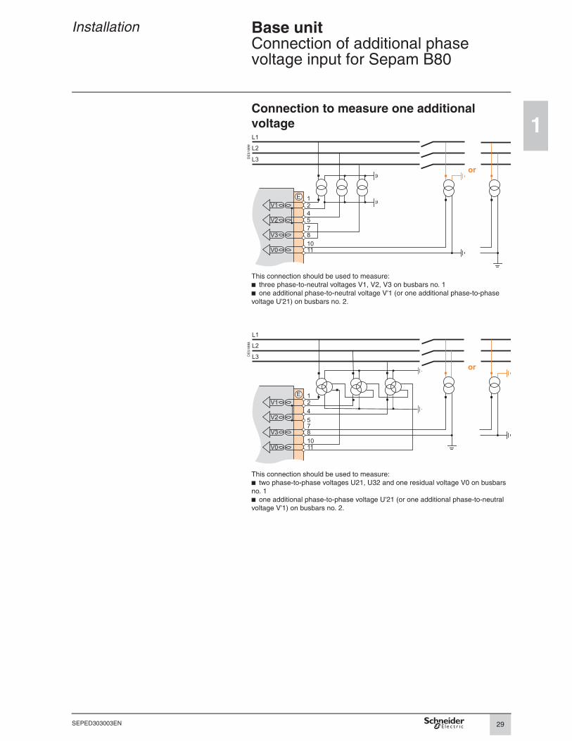
Installation Base unitConnection of additional phase voltage input for Sepam B80
Connection to measure one additional
voltage
DE
51
89
9
This connection should be used to measure:
b three phase-to-neutral voltages V1, V2, V3 on busbars no. 1
b one additional phase-to-neutral voltage V'1 (or one additional phase-to-phase
voltage U'21) on busbars no. 2.
DE
51
89
8
This connection should be used to measure:
b two phase-to-phase voltages U21, U32 and one residual voltage V0 on busbars
no. 1
b one additional phase-to-phase voltage U'21 (or one additional phase-to-neutral
voltage V'1) on busbars no. 2.

30
1
SEPED303003EN
Installation Base unitConnection of low voltage phase voltage inputs
Variant 1: TN-S and TN-C networks Variant 2: TT and IT networks
DE
80
98
2
DE
80
98
3
When a ground fault occurs on a TN-S or TN-C
network, the neutral potential is not affected: the neutral
can act as a reference for the VTs.
When a ground fault occurs on a TT or IT network, the neutral potential is affected:
the neutral cannot act as a reference for the VTs, phase-to-phase voltages must be
used on both phases.
N
10
11V0
N
V0
10
11