Embed Size (px)
Citation preview
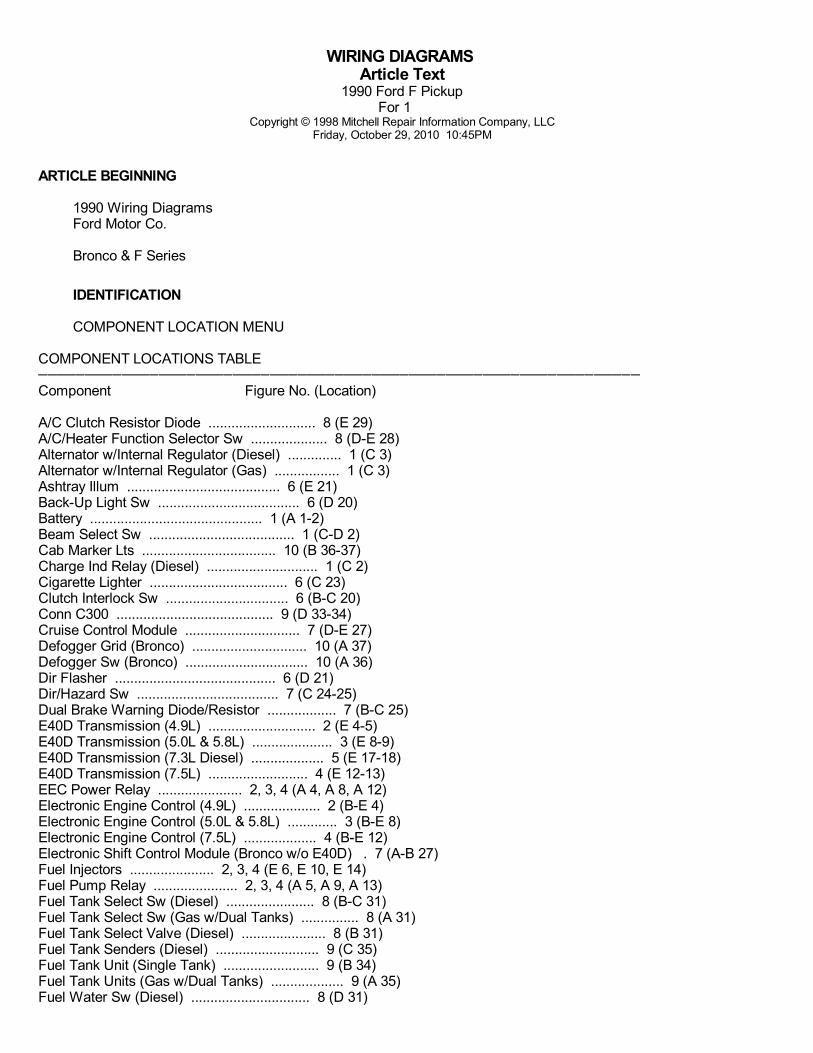
WIRING DIAGRAMS Article Text
1990 Ford F PickupFor 1
Copyright © 1998 Mitchell Repair Information Company, LLCFriday, October 29, 2010 10:45PM
ARTICLE BEGINNING
1990 Wiring Diagrams Ford Motor Co.
Bronco & F Series
IDENTIFICATION
COMPONENT LOCATION MENU
COMPONENT LOCATIONS TABLE
Component Figure No. (Location)
A/C Clutch Resistor Diode ............................ 8 (E 29)A/C/Heater Function Selector Sw .................... 8 (D-E 28)Alternator w/Internal Regulator (Diesel) .............. 1 (C 3)Alternator w/Internal Regulator (Gas) ................. 1 (C 3)Ashtray Illum ........................................ 6 (E 21)Back-Up Light Sw ..................................... 6 (D 20)Battery ............................................. 1 (A 1-2)Beam Select Sw ...................................... 1 (C-D 2)Cab Marker Lts ................................... 10 (B 36-37)Charge Ind Relay (Diesel) ............................. 1 (C 2)Cigarette Lighter .................................... 6 (C 23)Clutch Interlock Sw ................................ 6 (B-C 20)Conn C300 ......................................... 9 (D 33-34)Cruise Control Module .............................. 7 (D-E 27)Defogger Grid (Bronco) .............................. 10 (A 37)Defogger Sw (Bronco) ................................ 10 (A 36)Dir Flasher .......................................... 6 (D 21)Dir/Hazard Sw ..................................... 7 (C 24-25)Dual Brake Warning Diode/Resistor .................. 7 (B-C 25)E40D Transmission (4.9L) ............................ 2 (E 4-5)E40D Transmission (5.0L & 5.8L) ..................... 3 (E 8-9)E40D Transmission (7.3L Diesel) ................... 5 (E 17-18)E40D Transmission (7.5L) .......................... 4 (E 12-13)EEC Power Relay ...................... 2, 3, 4 (A 4, A 8, A 12)Electronic Engine Control (4.9L) .................... 2 (B-E 4)Electronic Engine Control (5.0L & 5.8L) ............. 3 (B-E 8)Electronic Engine Control (7.5L) ................... 4 (B-E 12)Electronic Shift Control Module (Bronco w/o E40D) . 7 (A-B 27)Fuel Injectors ...................... 2, 3, 4 (E 6, E 10, E 14)Fuel Pump Relay ...................... 2, 3, 4 (A 5, A 9, A 13)Fuel Tank Select Sw (Diesel) ....................... 8 (B-C 31)Fuel Tank Select Sw (Gas w/Dual Tanks) ............... 8 (A 31)Fuel Tank Select Valve (Diesel) ...................... 8 (B 31)Fuel Tank Senders (Diesel) ........................... 9 (C 35)Fuel Tank Unit (Single Tank) ......................... 9 (B 34)Fuel Tank Units (Gas w/Dual Tanks) ................... 9 (A 35)Fuel Water Sw (Diesel) ............................... 8 (D 31)
WIRING DIAGRAMS Article Text (p. 2)1990 Ford F Pickup
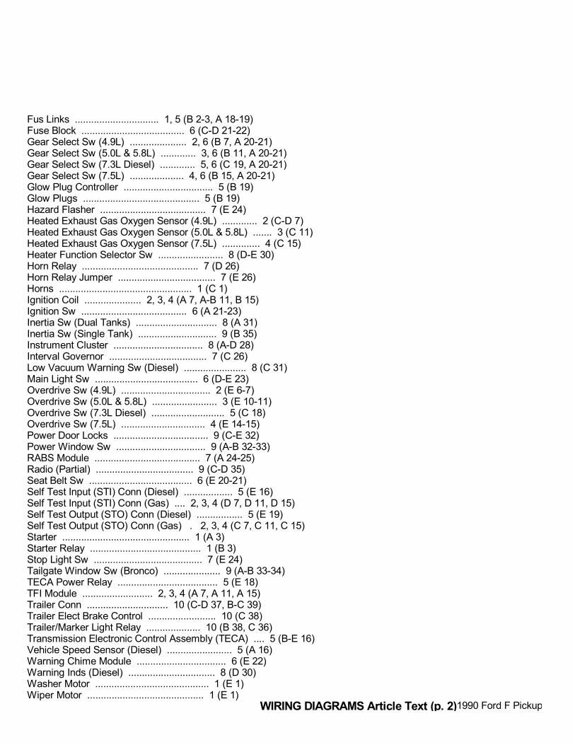
Fus Links ............................... 1, 5 (B 2-3, A 18-19)Fuse Block ...................................... 6 (C-D 21-22)Gear Select Sw (4.9L) ..................... 2, 6 (B 7, A 20-21)Gear Select Sw (5.0L & 5.8L) ............. 3, 6 (B 11, A 20-21)Gear Select Sw (7.3L Diesel) ............. 5, 6 (C 19, A 20-21)Gear Select Sw (7.5L) .................... 4, 6 (B 15, A 20-21)Glow Plug Controller ................................. 5 (B 19)Glow Plugs ........................................... 5 (B 19)Hazard Flasher ....................................... 7 (E 24)Heated Exhaust Gas Oxygen Sensor (4.9L) ............. 2 (C-D 7)Heated Exhaust Gas Oxygen Sensor (5.0L & 5.8L) ....... 3 (C 11)Heated Exhaust Gas Oxygen Sensor (7.5L) .............. 4 (C 15)Heater Function Selector Sw ........................ 8 (D-E 30)Horn Relay ........................................... 7 (D 26)Horn Relay Jumper .................................... 7 (E 26)Horns ................................................. 1 (C 1)Ignition Coil ..................... 2, 3, 4 (A 7, A-B 11, B 15)Ignition Sw ....................................... 6 (A 21-23)Inertia Sw (Dual Tanks) .............................. 8 (A 31)Inertia Sw (Single Tank) ............................. 9 (B 35)Instrument Cluster ................................. 8 (A-D 28)Interval Governor .................................... 7 (C 26)Low Vacuum Warning Sw (Diesel) ....................... 8 (C 31)Main Light Sw ...................................... 6 (D-E 23)Overdrive Sw (4.9L) ................................. 2 (E 6-7)Overdrive Sw (5.0L & 5.8L) ........................ 3 (E 10-11)Overdrive Sw (7.3L Diesel) ........................... 5 (C 18)Overdrive Sw (7.5L) ............................... 4 (E 14-15)Power Door Locks ................................... 9 (C-E 32)Power Window Sw ................................. 9 (A-B 32-33)RABS Module ....................................... 7 (A 24-25)Radio (Partial) .................................... 9 (C-D 35)Seat Belt Sw ...................................... 6 (E 20-21)Self Test Input (STI) Conn (Diesel) .................. 5 (E 16)Self Test Input (STI) Conn (Gas) .... 2, 3, 4 (D 7, D 11, D 15)Self Test Output (STO) Conn (Diesel) ................. 5 (E 19)Self Test Output (STO) Conn (Gas) . 2, 3, 4 (C 7, C 11, C 15)Starter ............................................... 1 (A 3)Starter Relay ......................................... 1 (B 3)Stop Light Sw ........................................ 7 (E 24)Tailgate Window Sw (Bronco) ..................... 9 (A-B 33-34)TECA Power Relay ..................................... 5 (E 18)TFI Module .......................... 2, 3, 4 (A 7, A 11, A 15)Trailer Conn .............................. 10 (C-D 37, B-C 39)Trailer Elect Brake Control ......................... 10 (C 38)Trailer/Marker Light Relay .................... 10 (B 38, C 36)Transmission Electronic Control Assembly (TECA) .... 5 (B-E 16)Vehicle Speed Sensor (Diesel) ........................ 5 (A 16)Warning Chime Module ................................. 6 (E 22)Warning Inds (Diesel) ................................ 8 (D 30)Washer Motor .......................................... 1 (E 1)Wiper Motor ........................................... 1 (E 1)
WIRING DIAGRAMS Article Text (p. 3)1990 Ford F PickupFor 1
Wiper/Washer Sw (Standard) ............................ 1 (E 3)Wiper/Washer Sw (w/Interval) ...................... 7 (D 26-27)4WD Ind Sw ........................................ 8 (B 29-30)4WD Shift Control Sw .............................. 7 (A 25-26)
WIRING DIAGRAMS
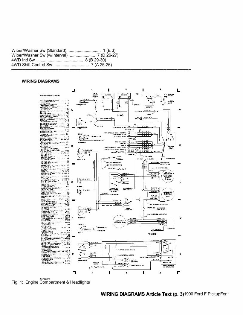
Fig. 1: Engine Compartment & Headlights
WIRING DIAGRAMS Article Text (p. 4)1990 Ford F PickupFor 1 Copyright © 1998 Mitchell Repair Information Company, LLC
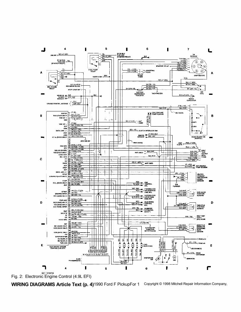
Fig. 2: Electronic Engine Control (4.9L EFI)
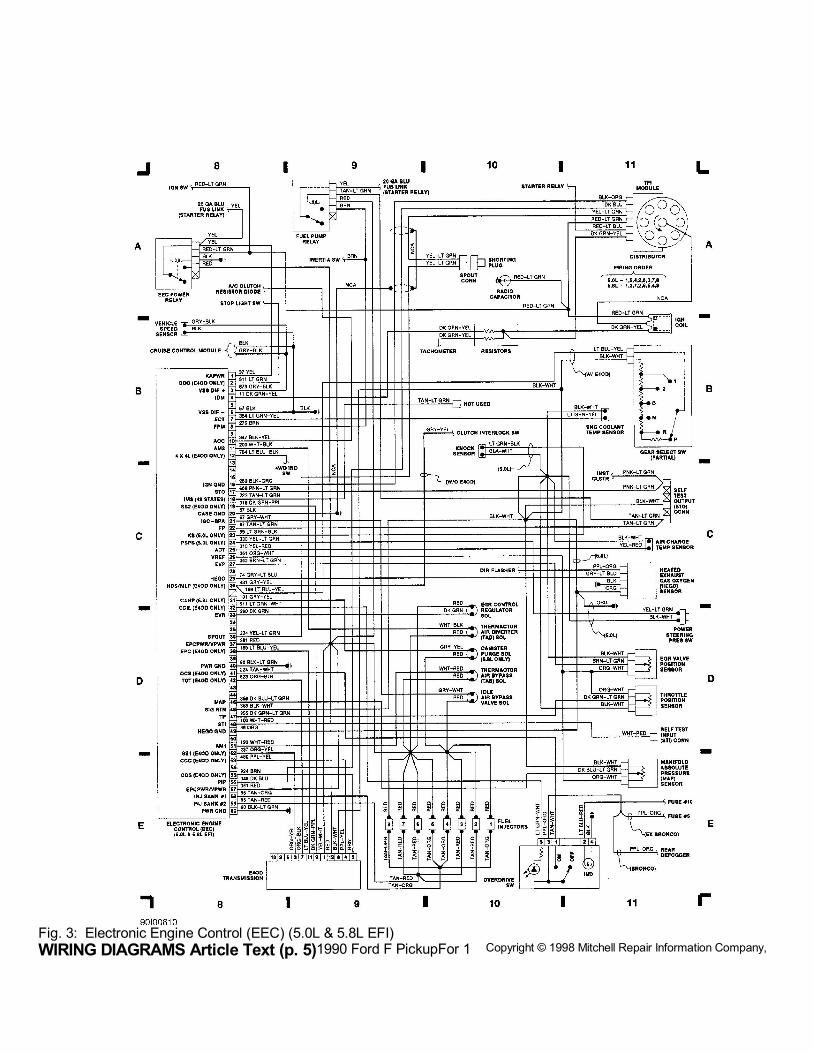
WIRING DIAGRAMS Article Text (p. 5)1990 Ford F PickupFor 1 Copyright © 1998 Mitchell Repair Information Company, LLCFig. 3: Electronic Engine Control (EEC) (5.0L & 5.8L EFI)
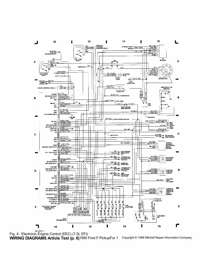
WIRING DIAGRAMS Article Text (p. 6)1990 Ford F PickupFor 1 Copyright © 1998 Mitchell Repair Information Company, LLCFig. 4: Electronic Engine Control (EEC) (7.5L EFI)
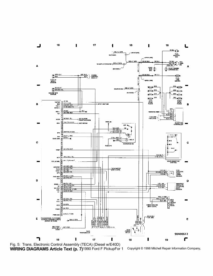
WIRING DIAGRAMS Article Text (p. 7)1990 Ford F PickupFor 1 Copyright © 1998 Mitchell Repair Information Company, LLCFig. 5: Trans. Electronic Control Assembly (TECA) (Diesel w/E40D)
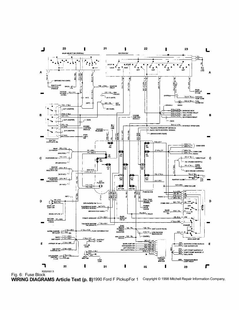
WIRING DIAGRAMS Article Text (p. 8)1990 Ford F PickupFor 1 Copyright © 1998 Mitchell Repair Information Company, LLCFig. 6: Fuse Block
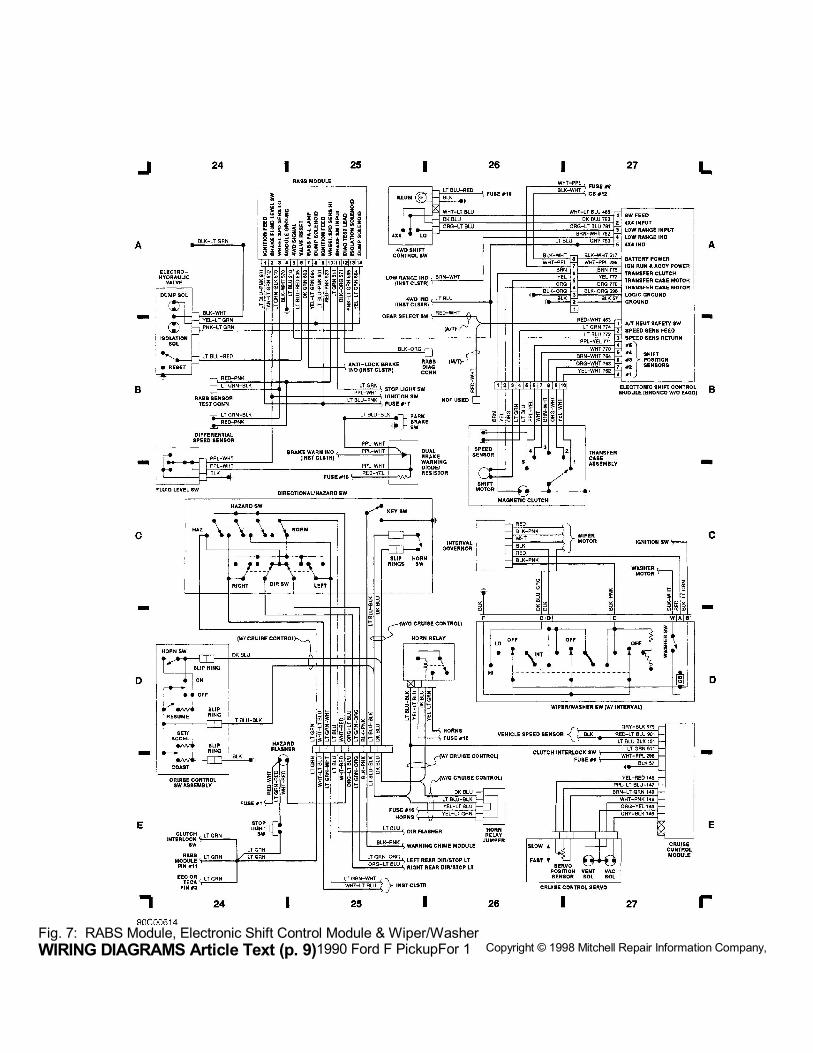
WIRING DIAGRAMS Article Text (p. 9)1990 Ford F PickupFor 1 Copyright © 1998 Mitchell Repair Information Company, LLCFig. 7: RABS Module, Electronic Shift Control Module & Wiper/Washer
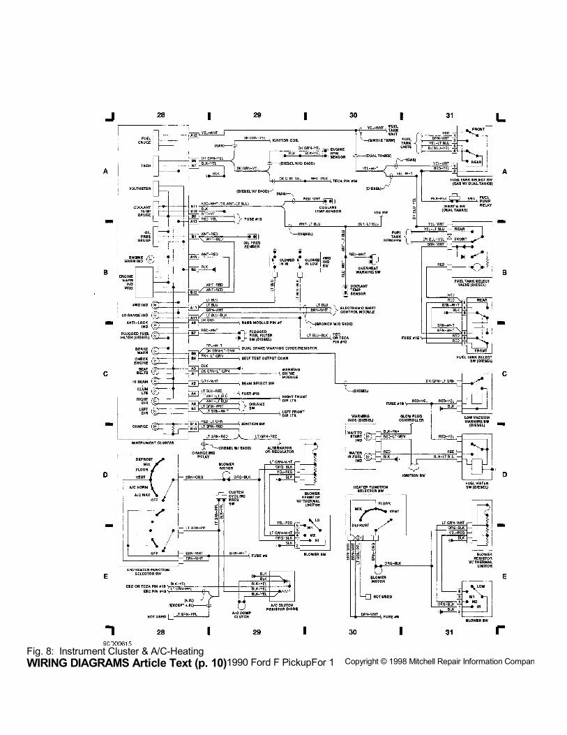
WIRING DIAGRAMS Article Text (p. 10)1990 Ford F PickupFor 1 Copyright © 1998 Mitchell Repair Information Company, LLCFig. 8: Instrument Cluster & A/C-Heating
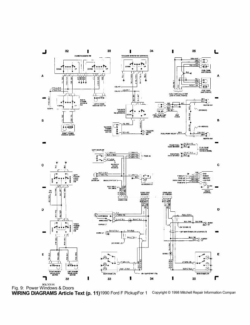
WIRING DIAGRAMS Article Text (p. 11)1990 Ford F PickupFor 1 Copyright © 1998 Mitchell Repair Information Company, LLCFig. 9: Power Windows & Doors
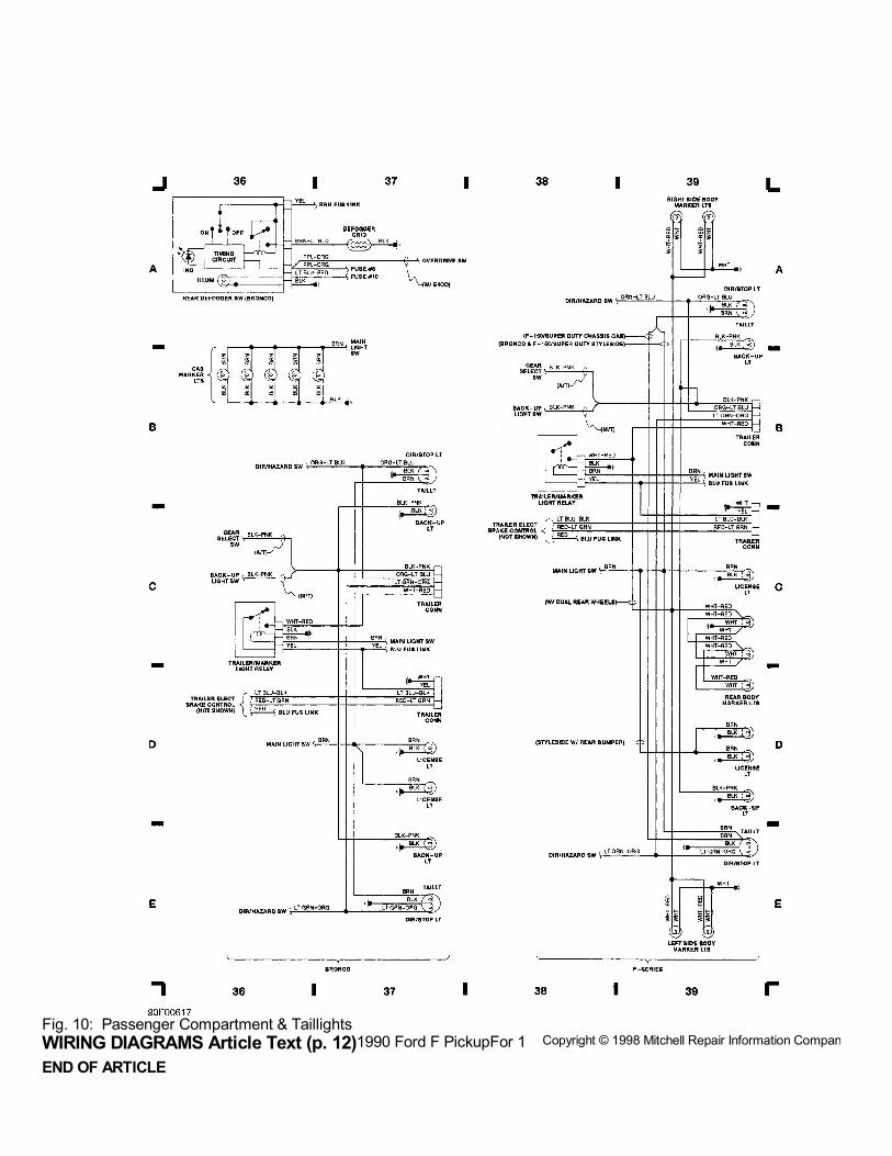
WIRING DIAGRAMS Article Text (p. 12)1990 Ford F PickupFor 1 Copyright © 1998 Mitchell Repair Information Company, LLCFig. 10: Passenger Compartment & Taillights
END OF ARTICLE