Embed Size (px)
Citation preview
® ®WKM DynaSeal 210 and 310Floating Ball Valves
D I S T R I B U T E D V A L V E S
®WKM
® ®WKM DYNASEAL 210DUCTILE IRON FLOATING BALL VALVES
How To Order 1
Features and Benefits 2
View and Specifications 4
Materials List 5
Dimensions and Weights 6
® ®WKM DYNASEAL 310FLOATING BALL VALVES
How To Order 7
Features and Benefits 9
11
Trim Chart 13
DIMENSIONAL DATA
4 in. (100 mm) Reduced Port and Smaller 14
Features and Benefits 16
18
Trim Chart 19
DIMENSIONAL DATA
4 in. (100 mm) Full Port and Larger 20
Pressure/Temperature Charts 22
Weights 24
Flow Characteristics 25
Stem Torques 26
WKM DynaSeal Material Selection Guide 28
TRADEMARK INFORMATION 35
Exploded
Exploded View and Specifications
Exploded View and Specifications
TABLE OF CONTENTS
D I S T R I B U T E D V A L V E S
CT-WKM-BALL-DYNASEAL-210-31005/09-ION-3M
®WKM
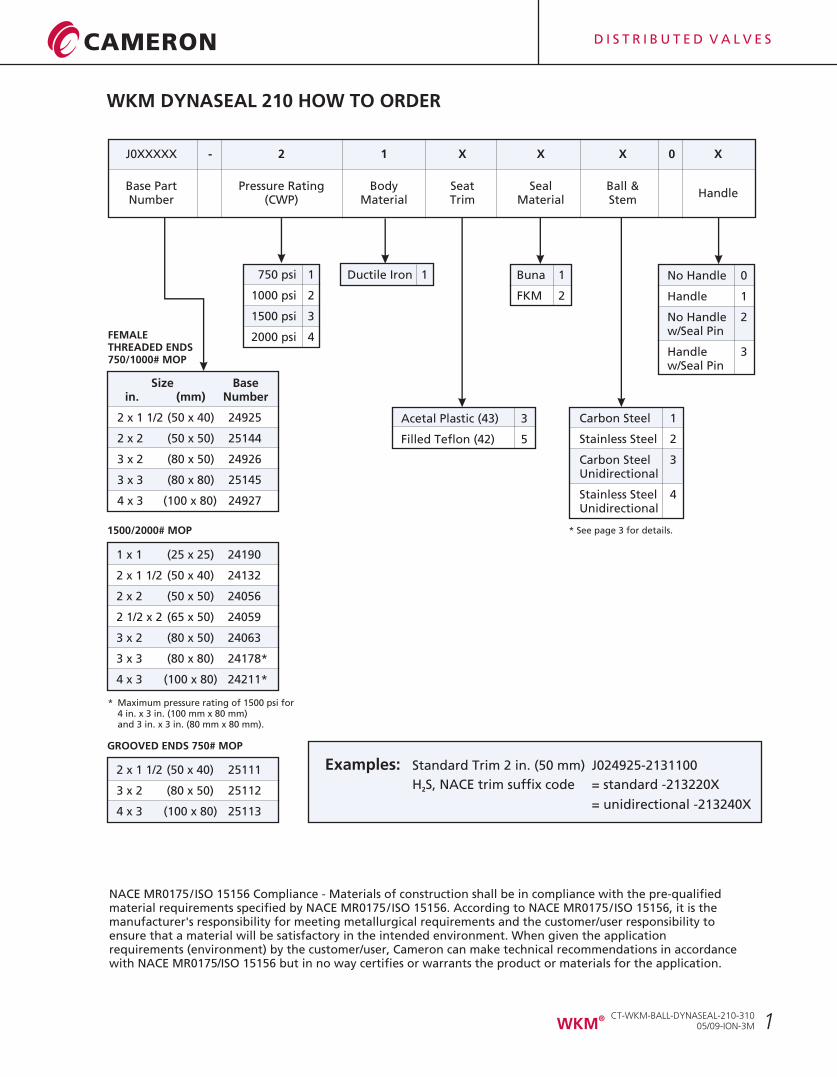
WKM DYNASEAL 210 HOW TO ORDER
1 x 1 (25 x 25) 24190
2 x 1 1/2 (50 x 40) 24132
2 x 2 (50 x 50) 24056
2 1/2 x 2 (65 x 50) 24059
3 x 2 (80 x 50) 24063
3 x 3 (80 x 80) 24178*
4 x 3 (100 x 80) 24211*
750 psi 1
1000 psi 2
1500 psi 3
2000 psi 4
* Maximum pressure rating of 1500 psi for4 in. x 3 in. (100 mm x 80 mm)and 3 in. x 3 in. (80 mm x 80 mm).
No Handle 0
Handle 1
No Handle 2w/Seal Pin
Handle 3w/Seal Pin
J0XXXXX - 2 1 X X X 0 X
Base Part Pressure Rating Body Seat Seal Ball &Handle
Number (CWP) Material Trim Material Stem
Carbon Steel 1
Stainless Steel 2
Carbon Steel 3Unidirectional
Stainless Steel 4Unidirectional
Ductile Iron 1 Buna 1
FKM 2
Acetal Plastic (43) 3
Filled Teflon (42) 5
Size Base in. (mm) Number
2 x 1 1/2 (50 x 40) 24925
2 x 2 (50 x 50) 25144
3 x 2 (80 x 50) 24926
3 x 3 (80 x 80) 25145
4 x 3 (100 x 80) 24927
FEMALETHREADED ENDS750/1000# MOP
1500/2000# MOP
2 x 1 1/2 (50 x 40) 25111
3 x 2 (80 x 50) 25112
4 x 3 (100 x 80) 25113
GROOVED ENDS 750# MOP
* See page 3 for details.
D I S T R I B U T E D V A L V E S
1
Examples: Standard Trim 2 in. (50 mm) J024925-2131100
H S, NACE trim suffix code = standard -213220X2
= unidirectional -213240X
NACE MR0175/ISO 15156 Compliance - Materials of construction shall be in compliance with the pre-qualified material requirements specified by NACE MR0175/ISO 15156. According to NACE MR0175/ISO 15156, it is the manufacturer's responsibility for meeting metallurgical requirements and the customer/user responsibility to ensure that a material will be satisfactory in the intended environment. When given the application requirements (environment) by the customer/user, Cameron can make technical recommendations in accordance with NACE MR0175/ISO 15156 but in no way certifies or warrants the product or materials for the application.
CT-WKM-BALL-DYNASEAL-210-31005/09-ION-3M
®WKM
2
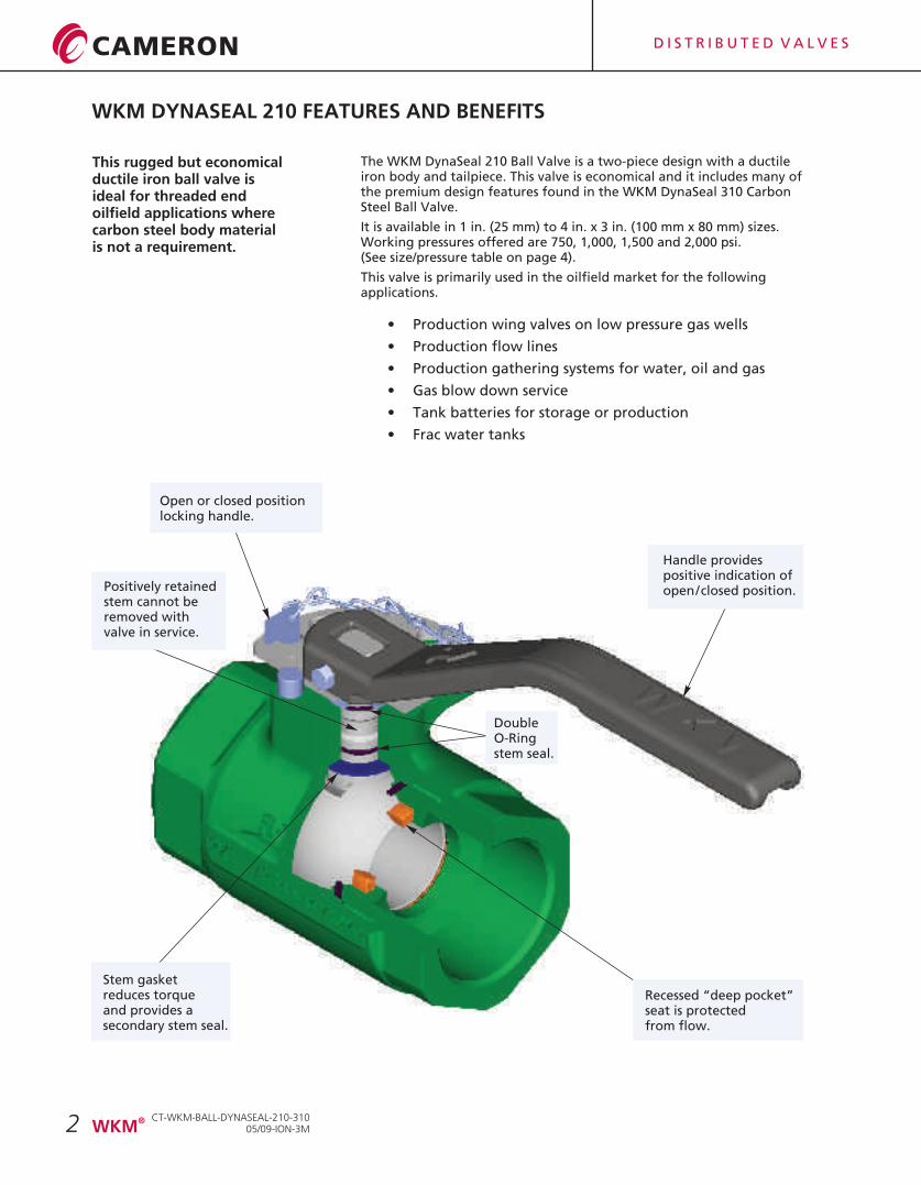
This rugged but economical ductile iron ball valve is ideal for threaded end oilfield applications where carbon steel body material is not a requirement.
Open or closed positionlocking handle.
Positively retainedstem cannot beremoved withvalve in service.
Handle providespositive indication ofopen/closed position.
WKM DYNASEAL 210 FEATURES AND BENEFITS
The WKM DynaSeal 210 Ball Valve is a two-piece design with a ductile iron body and tailpiece. This valve is economical and it includes many of the premium design features found in the WKM DynaSeal 310 Carbon Steel Ball Valve.
It is available in 1 in. (25 mm) to 4 in. x 3 in. (100 mm x 80 mm) sizes. Working pressures offered are 750, 1,000, 1,500 and 2,000 psi.(See size/pressure table on page 4).
This valve is primarily used in the oilfield market for the following applications.
• Production wing valves on low pressure gas wells
• Production flow lines
• Production gathering systems for water, oil and gas
• Gas blow down service
• Tank batteries for storage or production
• Frac water tanks
Recessed “deep pocket”seat is protectedfrom flow.
Stem gasketreduces torqueand provides asecondary stem seal.
DoubleO-Ringstem seal.
D I S T R I B U T E D V A L V E S
CT-WKM-BALL-DYNASEAL-210-31005/09-ION-3M
®WKM
3
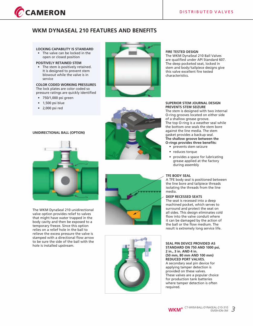
UNIDIRECTIONAL BALL (OPTION)
The WKM DynaSeal 210 unidirectional valve option provides relief to valves that might have water trapped in the body cavity and then be exposed to a temporary freeze. Since this option relies on a relief hole in the ball to relieve the excess pressure the valve is stamped with a directional flow arrow to be sure the side of the ball with the hole is installed upstream.
SUPERIOR STEM JOURNAL DESIGN PREVENTS STEM SEIZUREThe stem is designed with two internal O-ring grooves located on either side of a shallow grease groove.The top O-ring is a weather seal while the bottom one seals the stem boreagainst the line media. The stem gasket provides a backup seal.The shallow groove between the O-rings provides three benefits:
• prevents stem seizure
• reduces torque
• provides a space for lubricating grease applied at the factory during assembly
TFE BODY SEALA TFE body seal is positioned between the line bore and tailpiece threads isolating the threads from the line media.
DEEP RECESSED SEATS The seat is recessed into a deep machined pocket, which serves to surround and protect the seat on all sides. This design eliminates cold flow into the valve conduit where it can be damaged by the action of the ball or the flow medium. The result is extremely long service life.
SEAL PIN DEVICE PROVIDED AS STANDARD ON 750 AND 1000 psi,2 in., 3 in. AND 4 in.(50 mm, 80 mm AND 100 mm) REDUCED PORT VALVES.A secondary seal pin device for applying tamper detection is provided on these valves.These valves are a popular choice for production tank batteries where tamper detection is often required.
FIRE TESTED DESIGNThe WKM DynaSeal 210 Ball Valves are qualified under API Standard 607.The deep pocketed seat, locked in stem and body/tailpiece designs give this valve excellent fire tested characteristics.
LOCKING CAPABILITY IS STANDARD• The valve can be locked in the
open or closed position
POSITIVELY RETAINED STEM• The stem is positively retained.
It is designed to prevent stem blowout while the valve is in service
COLOR CODED WORKING PRESSURESThe lock plates are color coded so pressure ratings are quickly identified
• 750/1,000 psi green
• 1,500 psi blue
• 2,000 psi red
WKM DYNASEAL 210 FEATURES AND BENEFITS
D I S T R I B U T E D V A L V E S
CT-WKM-BALL-DYNASEAL-210-31005/09-ION-3M
®WKM
4
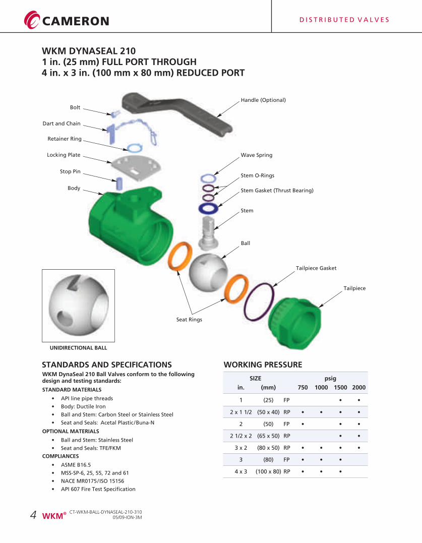
WKM DYNASEAL 2101 in. (25 mm) FULL PORT THROUGH4 in. x 3 in. (100 mm x 80 mm) REDUCED PORT
WKM DynaSeal 210 Ball Valves conform to the following design and testing standards:
STANDARD MATERIALS
• API line pipe threads
• Body: Ductile Iron
• Ball and Stem: Carbon Steel or Stainless Steel
• Seat and Seals: Acetal Plastic/Buna-N
OPTIONAL MATERIALS
• Ball and Stem: Stainless Steel
• Seat and Seals: TFE/FKM
COMPLIANCES
• ASME B16.5
• MSS-SP-6, 25, 55, 72 and 61
• NACE
• API 607 Fire Test Specification
MR0175/ISO 15156
STANDARDS AND SPECIFICATIONS
SIZE psig
in. (mm) 750 1000 1500 2000
1 (25) FP • •
2 x 1 1/2 (50 x 40) RP • • • •
2 (50) FP • • •
2 1/2 x 2 (65 x 50) RP • •
3 x 2 (80 x 50) RP • • • •
3 (80) FP • • •
4 x 3 (100 x 80) RP • • •
WORKING PRESSURE
Ball
Stem Gasket (Thrust Bearing)
Stem
Stem O-Rings
Tailpiece Gasket
Seat Rings
Tailpiece
Locking Plate
Stop Pin
Retainer Ring
Handle (Optional)
Wave Spring
Dart and Chain
Bolt
Body
UNIDIRECTIONAL BALL
D I S T R I B U T E D V A L V E S
CT-WKM-BALL-DYNASEAL-210-31005/09-ION-3M
®WKM
5
WKM DYNASEAL 2101 in. (25 mm) FULL PORT THROUGH4 in. x 3 in. (100 mm x 80 mm) REDUCED PORT750, 1000, 1500 and 2000 psig WORKING PRESSURE
STANDARD MATERIALS
Qty. DESCRIPTION MATERIAL
1 Body ASTM A395 Ductile Iron
1 Tailpiece ASTM A395 Ductile Iron
1 Ball Carbon Steel Chrome Plated316 SS
1 Stem AISI 1213/1215, Steel, Zinc Plated 316 SS (Type 630 on 2 in. x 1 1/2 in. (50 mm x 40 mm))
2 Seat Ring Acetal Plastic (43)Filled TFE (42)
1 Tailpiece Gasket PTFE
2 Stem O-Ring Buna-NFKM
1 Stem Gasket (Thrust Bearing) Filled TFE
1 Locking Plate Steel 1018/26
1 Locking Plate Retaining Ring Spring Steel
1 Wave Spring Spring Steel
1 Stop Pin Spring Steel
1 Handle ASTM A395 Ductile Iron
1 Seal Pin/Dart Brass or Aluminum
Note: For H S service use Trim Code -X13220X. Meets NACE (see “How To Order” page 1).2 MR0175/ISO 15156
CT-WKM-BALL-DYNASEAL-210-31005/09-ION-3M
®WKM
D I S T R I B U T E D V A L V E S
6
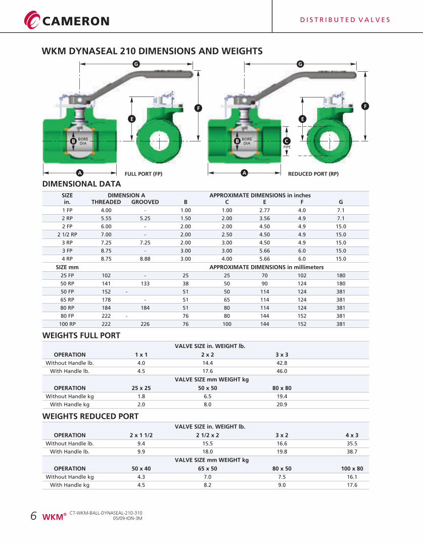
WKM DYNASEAL 210 DIMENSIONS AND WEIGHTS
FULL PORT (FP) REDUCED PORT (RP)
DIMENSIONAL DATA
SIZE DIMENSION A in. THREADED GROOVED B C E F G
1 FP 4.00 - 1.00 1.00 2.77 4.0 7.1
2 RP 5.55 5.25 1.50 2.00 3.56 4.9 7.1
2 FP 6.00 - 2.00 2.00 4.50 4.9 15.0
2 1/2 RP 7.00 - 2.00 2.50 4.50 4.9 15.0
3 RP 7.25 7.25 2.00 3.00 4.50 4.9 15.0
3 FP 8.75 - 3.00 3.00 5.66 6.0 15.0
4 RP 8.75 8.88 3.00 4.00 5.66 6.0 15.0
SIZE mm APPROXIMATE DIMENSIONS in millimeters
25 FP 102 - 25 25 70 102 180
50 RP 141 133 38 50 90 124 180
50 FP 152 - 51 50 114 124 381
65 RP 178 - 51 65 114 124 381
80 RP 184 184 51 80 114 124 381
80 FP 222 - 76 80 144 152 381
100 RP 222 226 76 100 144 152 381
APPROXIMATE DIMENSIONS in inches
WEIGHTS FULL PORT
WEIGHTS REDUCED PORTVALVE SIZE in. WEIGHT lb.
OPERATION 2 x 1 1/2 2 1/2 x 2 3 x 2 4 x 3
Without Handle lb. 9.4 15.5 16.6 35.5
With Handle lb. 9.9 18.0 19.8 38.7
VALVE SIZE mm WEIGHT kg
OPERATION 50 x 40 65 x 50 80 x 50 100 x 80
Without Handle kg 4.3 7.0 7.5 16.1
With Handle kg 4.5 8.2 9.0 17.6
VALVE SIZE in. WEIGHT lb.
OPERATION 1 x 1 2 x 2 3 x 3
Without Handle lb. 4.0 14.4 42.8
With Handle lb. 4.5 17.6 46.0
VALVE SIZE mm WEIGHT kg
OPERATION 25 x 25 50 x 50 80 x 80
Without Handle kg 1.8 6.5 19.4
With Handle kg 2.0 8.0 20.9
PIPE
A
E
B BOREDIAB
BOREDIA
F
C
A
G G
F
E
CT-WKM-BALL-DYNASEAL-210-31005/09-ION-3M
®WKM
D I S T R I B U T E D V A L V E S
7
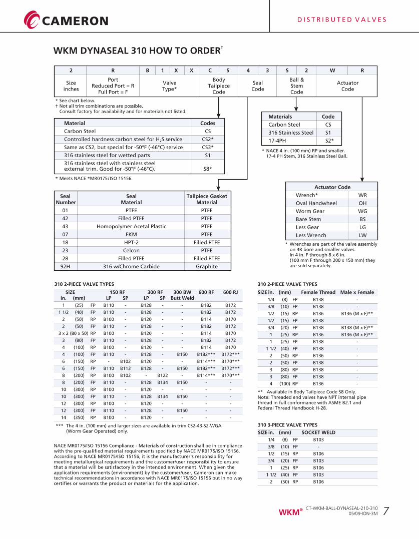
†WKM DYNASEAL 310 HOW TO ORDER
Seal Seal Tailpiece Gasket Number Material Material
01 PTFE PTFE
42 Filled PTFE PTFE
43 Homopolymer Acetal Plastic PTFE
07 FKM PTFE
18 HPT-2 Filled PTFE
23 Celcon PTFE
28 Filled PTFE Filled PTFE
92H 316 w/Chrome Carbide Graphite
Materials Code
Carbon Steel CS
316 Stainless Steel S1
17-4PH S2*
Material Codes
Carbon Steel CS
Controlled hardness carbon steel for H S service CS2*2
Same as CS2, but special for -50°F (-46°C) service CS3*
316 stainless steel for wetted parts S1
316 stainless steel with stainless steelexternal trim. Good for -50°F (-46°C). S8*
* Meets NACE *MR0175/ISO 15156.
* NACE 4 in. (100 mm) RP and smaller. 17-4 PH Stem, 316 Stainless Steel Ball.
Actuator Code
Wrench* WR
Oval Handwheel OH
Worm Gear WG
Bare Stem BS
Less Gear LG
Less Wrench LW
* Wrenches are part of the valve assemblyon 4R bore and smaller valves.In 4 in. F through 8 x 6 in. (100 mm F through 200 x 150 mm) they are sold separately.
310 2-PIECE VALVE TYPES
SIZE 150 RF 300 RF 300 BW 600 RF 600 RJin. (mm) LP SP LP SP Butt Weld
1 (25) FP B110 - B128 - - B182 B172
1 1/2 (40) FP B110 - B128 - - B182 B172
2 (50) RP B100 - B120 - - B114 B170
2 (50) FP B110 - B128 - - B182 B172
3 x 2 (80 x 50) RP B100 - B120 - - B114 B170
3 (80) FP B110 - B128 - - B182 B172
4 (100) RP B100 - B120 - - B114 B170
4 (100) FP B110 - B128 - B150 B182*** B172***
6 (150) RP - B102 B120 - - B114*** B170***
6 (150) FP B110 B113 B128 - B150 B182*** B172***
8 (200) RP B100 B102 - B122 - B114*** B170***
8 (200) FP B110 - B128 B134 B150 - -
10 (300) RP B100 - B120 - - - -
10 (300) FP B110 - B128 B134 B150 - -
12 (300) RP B100 - B120 - - - -
12 (300) FP B110 - B128 - B150 - -
14 (350) RP B100 - B120 - - - -
*** The 4 in. (100 mm) and larger sizes are available in trim CS2-43-S2-WGA(Worm Gear Operated) only.
310 3-PIECE VALVE TYPES
SIZE in. (mm) SOCKET WELD
1/4 (8) FP B103
3/8 (10) FP -
1/2 (15) RP B106
3/4 (20) FP B103
1 (25) RP B106
1 1/2 (40) FP B103
2 (50) RP B106
2 R B 1 X X C S 4 3 S 2 W R
Port Body Ball &Size Valve Seal Actuator
Reduced Port = R Tailpiece Steminches Type* Code Code
Full Port = F Code Code
NACE MR0175/ISO 15156 Compliance - Materials of construction shall be in compliance with the pre-qualified material requirements specified by NACE MR0175/ISO 15156. According to NACE MR0175/ISO 15156, it is the manufacturer's responsibility for meeting metallurgical requirements and the customer/user responsibility to ensure that a material will be satisfactory in the intended environment. When given the application requirements (environment) by the customer/user, Cameron can make technical recommendations in accordance with NACE MR0175/ISO 15156 but in no way certifies or warrants the product or materials for the application.
** Available in Body Tailpiece Code S8 Only.Note: Threaded end valves have NPT internal pipe thread in full conformance with ASME B2.1 andFederal Thread Handbook H-28.
310 2-PIECE VALVE TYPES
SIZE in. (mm) Female Thread Male x Female
1/4 (8) FP B138 -
3/8 (10) FP B138 -
1/2 (15) RP B136 B136 (M x F)**
1/2 (15) FP B138 -
3/4 (20) FP B138 B138 (M x F)**
1 (25) RP B136 B136 (M x F)**
1 (25) FP B138 -
1 1/2 (40) FP B138 -
2 (50) RP B136 -
2 (50) FP B138 -
3 (80) RP B138 -
3 (80) FP B138 -
4 (100) RP B136 -
CT-WKM-BALL-DYNASEAL-210-31005/09-ION-3M
®WKM
* See chart below.† Not all trim combinations are possible.
Consult factory for availability and for materials not listed.
D I S T R I B U T E D V A L V E S
8
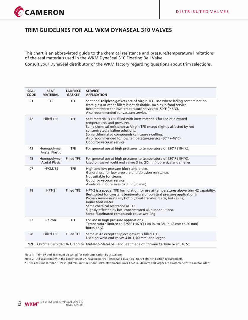
TRIM GUIDELINES FOR ALL WKM DYNASEAL 310 VALVES
SEAL SEAT TAILPIECE SERVICECODE MATERIAL GASKET APPLICATION
01 TFE TFE Seat and Tailpiece gaskets are of Virgin TFE. Use where lading contamination from glass or other fillers is not desirable, such as in food service. Recommended for low temperature service to -50°F (-46°C).Also recommended for vacuum service.
42 Filled TFE TFE Seat material is TFE filled with inert materials for use at elevated temperatures and pressures.Same chemical resistance as Virgin TFE except slightly affected by hot concentrated alkaline solutions.Some chlorinated compounds can cause swelling. Also recommended for low temperature service -50°F (-46°C).Good for vacuum service.
43 Homopolymer TFE For general use at high pressures to temperature of 220°F (104°C).Acetal Plastic
48 Homopolymer Filled TFE For general use at high pressures to temperature of 220°F (104°C).Acetal Plasic Used on socket weld end valves 3 in. (80 mm) bore size and smaller.
07 *FKM/SS TFE High and low pressure block-and-bleed.General use for low pressure and abrasion resistance.Not suitable for steam. Good for vacuum service.Available in bore sizes to 3 in. (80 mm).
18 HPT-2 Filled TFE HPT-2 is a special TFE formulation for use at temperatures above trim 42 capability.Best suited for constant temperature or constant pressure applications.Proven service in steam, hot oil, heat transfer fluids, hot resins, boiler feed water. Same chemical resistance as TFE.Slightly affected by hot, concentrated alkaline solutions.Some fluorinated compounds cause swelling.
23 Celcon TFE For use in high pressure applications.Temperature limited to 225°F (107°C) (1/4 in. to 3/4 in. (8 mm to 20 mm) bores only).
28 Filled TFE Filled TFE Same as 42 except tailpiece gasket is filled TFE.Used on weld end valves 4 in. (100 mm) and larger.
92H Chrome Carbide/316 Graphite Metal-to-Metal ball and seat made of Chrome Carbide over 316 SS
Note 1: Trim 07 and 18 should be tested for each application by actual use.
Note 2: All seal codes with the exception of 07, have been Fire Tested (and qualified) to API 607 4th Edition requirements.
* Trim sizes smaller than 1 1/2 in. (40 mm) in trim 07 are 100% elastomeric. Sizes 1 1/2 in. (40 mm) and larger are elastomeric with a metal insert.
This chart is an abbreviated guide to the chemical resistance and pressure/temperature limitationsof the seal materials used in the WKM DynaSeal 310 Floating Ball Valve.
Consult your DynaSeal distributor or the WKM factory regarding questions about trim selections.
CT-WKM-BALL-DYNASEAL-210-31005/09-ION-3M
®WKM
D I S T R I B U T E D V A L V E S
9
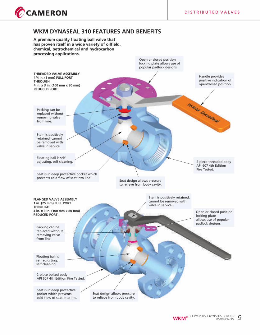
A premium quality floating ball valve that has proven itself in a wide variety of oilfield, chemical, petrochemical and hydrocarbon processing applications.
WKM DYNASEAL 310 FEATURES AND BENEFITS
THREADED VALVE ASSEMBLY1/4 in. (8 mm) FULL PORTTHROUGH4 in. x 3 in. (100 mm x 80 mm)REDUCED PORT.
FLANGED VALVE ASSEMBLY1 in. (25 mm) FULL PORTTHROUGH4 in. x 3 in. (100 mm x 80 mm)REDUCED PORT.
Packing can bereplaced withoutremoving valvefrom line.
Handle providespositive indication ofopen/closed position.
Seat is in deep protective pocket whichprevents cold flow of seat into line.
Stem is positivelyretained, cannotbe removed withvalve in service.
Floating ball is selfadjusting, self cleaning.
Packing can bereplaced withoutremoving valvefrom line.
Floating ball isself adjusting,self cleaning.
Stem is positively retained,cannot be removed withvalve in service.
Open or closed positionlocking plateallows use of popularpadlock designs.
2-piece bolted bodyAPI 607 4th Edition Fire Tested.
2-piece threaded bodyAPI 607 4th EditionFire Tested.
Open or closed positionlocking plate allows use ofpopular padlock designs.
Seat design allows pressureto relieve from body cavity.
Seat is in deep protectivepocket which preventscold flow of seat into line.
Seat design allows pressureto relieve from body cavity.
CT-WKM-BALL-DYNASEAL-210-31005/09-ION-3M
®WKM
D I S T R I B U T E D V A L V E S
10
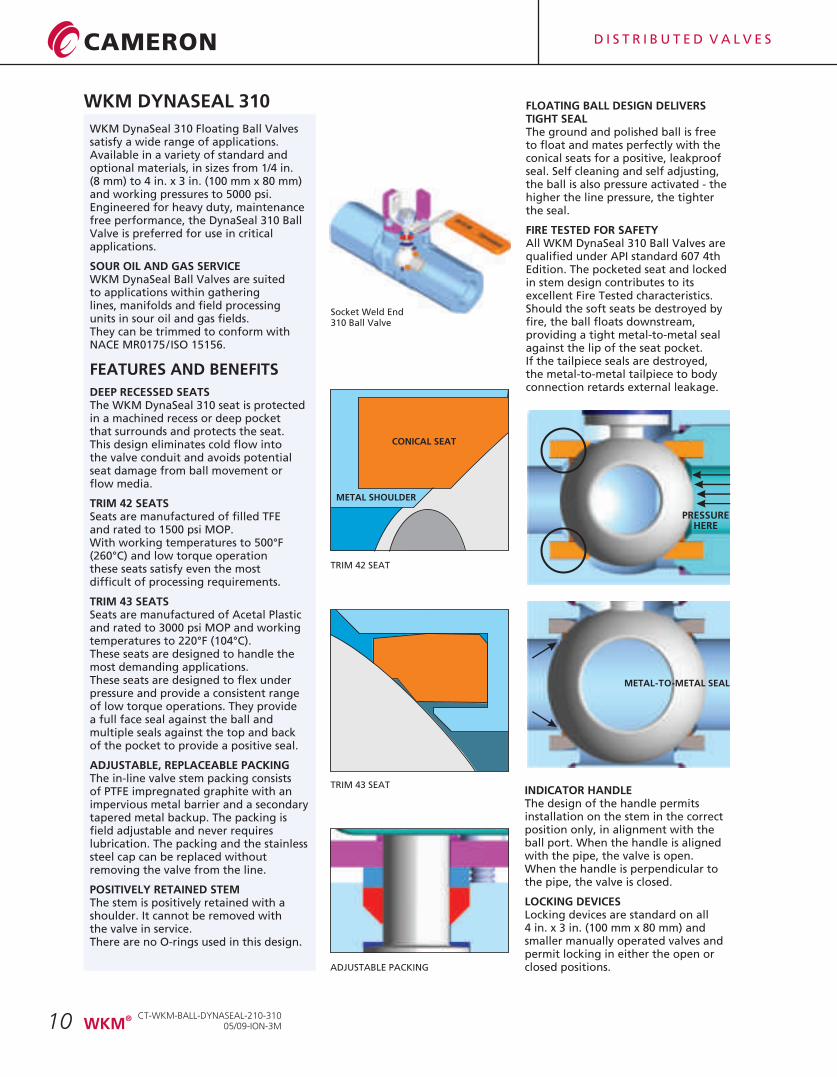
WKM DynaSeal 310 Floating Ball Valves satisfy a wide range of applications. Available in a variety of standard and optional materials, in sizes from 1/4 in. (8 mm) to 4 in. x 3 in. (100 mm x 80 mm) and working pressures to 5000 psi. Engineered for heavy duty, maintenance free performance, the DynaSeal 310 Ball Valve is preferred for use in critical applications.
SOUR OIL AND GAS SERVICEWKM DynaSeal Ball Valves are suited to applications within gathering lines, manifolds and field processing units in sour oil and gas fields. They can be trimmed to conform with NACE MR0175/ISO 15156.
DEEP RECESSED SEATS The WKM DynaSeal 310 seat is protected in a machined recess or deep pocket that surrounds and protects the seat. This design eliminates cold flow into the valve conduit and avoids potential seat damage from ball movement or flow media.
TRIM 42 SEATSSeats are manufactured of filled TFE and rated to 1500 psi MOP. With working temperatures to 500°F (260°C) and low torque operation these seats satisfy even the most difficult of processing requirements.
TRIM 43 SEATS Seats are manufactured of Acetal Plastic and rated to 3000 psi MOP and working temperatures to 220°F (104°C). These seats are designed to handle the most demanding applications. These seats are designed to flex under pressure and provide a consistent range of low torque operations. They provide a full face seal against the ball and multiple seals against the top and back of the pocket to provide a positive seal.
ADJUSTABLE, REPLACEABLE PACKINGThe in-line valve stem packing consists of PTFE impregnated graphite with an impervious metal barrier and a secondary tapered metal backup. The packing is field adjustable and never requires lubrication. The packing and the stainless steel cap can be replaced without removing the valve from the line.
POSITIVELY RETAINED STEM The stem is positively retained with a shoulder. It cannot be removed with the valve in service. There are no O-rings used in this design.
FEATURES AND BENEFITS
PRESSUREHERE
FLOATING BALL DESIGN DELIVERS TIGHT SEAL The ground and polished ball is free to float and mates perfectly with the conical seats for a positive, leakproof seal. Self cleaning and self adjusting, the ball is also pressure activated - the higher the line pressure, the tighter the seal.
FIRE TESTED FOR SAFETYAll WKM DynaSeal 310 Ball Valves are qualified under API standard 607 4th Edition. The pocketed seat and locked in stem design contributes to its excellent Fire Tested characteristics. Should the soft seats be destroyed by fire, the ball floats downstream, providing a tight metal-to-metal seal against the lip of the seat pocket. If the tailpiece seals are destroyed, the metal-to-metal tailpiece to body connection retards external leakage.
TRIM 42 SEAT
INDICATOR HANDLEThe design of the handle permits installation on the stem in the correct position only, in alignment with the ball port. When the handle is aligned with the pipe, the valve is open.When the handle is perpendicular to the pipe, the valve is closed.
LOCKING DEVICES Locking devices are standard on all4 in. x 3 in. (100 mm x 80 mm) and smaller manually operated valves and permit locking in either the open or closed positions.
TRIM 43 SEAT
METAL-TO-METAL SEAL
ADJUSTABLE PACKING
CONICAL SEAT
METAL SHOULDER
WKM DYNASEAL 310
Socket Weld End310 Ball Valve
CT-WKM-BALL-DYNASEAL-210-31005/09-ION-3M
®WKM
D I S T R I B U T E D V A L V E S
11
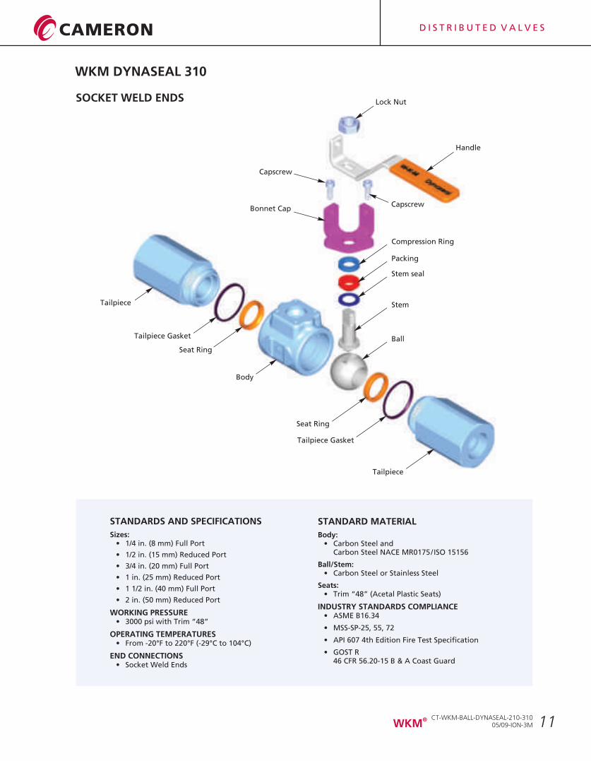
STANDARD MATERIAL
Body:• Carbon Steel and
Carbon Steel NACE
Ball/Stem:• Carbon Steel or Stainless Steel
Seats: • Trim “48” (Acetal Plastic Seats)
INDUSTRY STANDARDS COMPLIANCE • ASME B16.34
• MSS-SP-25, 55, 72
• API 607 4th Edition Fire Test Specification
• GOST R 46 CFR 56.20-15 B & A Coast Guard
MR0175/ISO 15156
SOCKET WELD ENDS Lock Nut
Tailpiece
Tailpiece Gasket
Handle
Compression Ring
Packing
Stem seal
Stem
Ball
Bonnet Cap
Seat Ring
Body
Seat Ring
Tailpiece Gasket
Tailpiece
Capscrew
Capscrew
WKM DYNASEAL 310
STANDARDS AND SPECIFICATIONS
Sizes:• 1/4 in. (8 mm) Full Port
• 1/2 in. (15 mm) Reduced Port
• 3/4 in. (20 mm) Full Port
• 1 in. (25 mm) Reduced Port
• 1 1/2 in. (40 mm) Full Port
• 2 in. (50 mm) Reduced Port
WORKING PRESSURE • 3000 psi with Trim “48”
OPERATING TEMPERATURES• From -20°F to 220°F (-29°C to 104°C)
END CONNECTIONS• Socket Weld Ends
CT-WKM-BALL-DYNASEAL-210-31005/09-ION-3M
®WKM
D I S T R I B U T E D V A L V E S
12
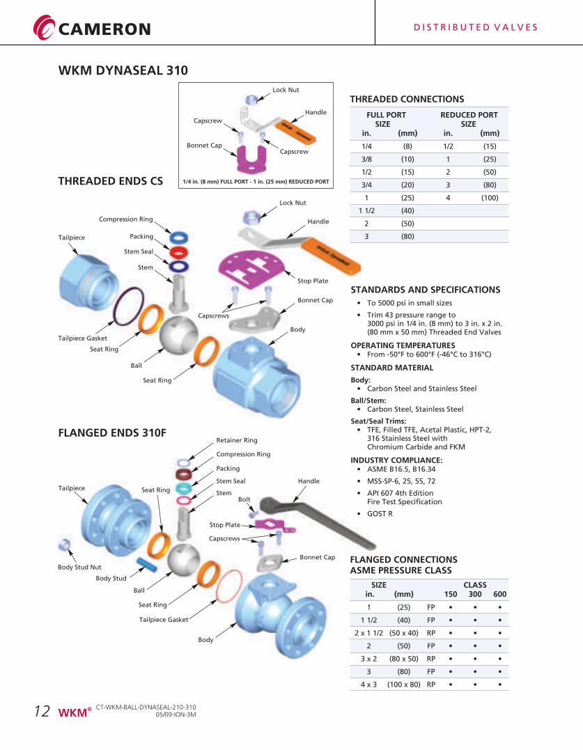
STANDARDS AND SPECIFICATIONS
• To 5000 psi in small sizes
• Trim 43 pressure range to3000 psi in 1/4 in. (8 mm) to 3 in. x 2 in.(80 mm x 50 mm) Threaded End Valves
OPERATING TEMPERATURES• From -50°F to 600°F (-46°C to 316°C)
STANDARD MATERIAL
Body:• Carbon Steel and Stainless Steel
Ball/Stem:• Carbon Steel, Stainless Steel
Seat/Seal Trims:• TFE, Filled TFE, Acetal Plastic, HPT-2,
316 Stainless Steel withChromium Carbide and FKM
INDUSTRY COMPLIANCE:• ASME B16.5, B16.34
• MSS-SP-6, 25, 55, 72
• API 607 4th Edition Fire Test Specification
• GOST R
FLANGED CONNECTIONSASME PRESSURE CLASS
SIZE CLASS in. (mm) 150 300 600
1 (25) FP • • •
1 1/2 (40) FP • • •
2 x 1 1/2 (50 x 40) RP • • •
2 (50) FP • • •
3 x 2 (80 x 50) RP • • •
3 (80) FP • • •
4 x 3 (100 x 80) RP • • •
FLANGED ENDS 310F
THREADED ENDS CS
THREADED CONNECTIONS
FULL PORT REDUCED PORTSIZE SIZE
in. (mm) in. (mm)
1/4 (8) 1/2 (15)
3/8 (10) 1 (25)
1/2 (15) 2 (50)
3/4 (20) 3 (80)
1 (25) 4 (100)
1 1/2 (40)
2 (50)
3 (80)
Lock Nut
Handle
Stop Plate
Bonnet Cap
Body
Tailpiece
Compression Ring
Packing
Stem Seal
Stem
Tailpiece Gasket
Seat Ring
Ball
Seat Ring
Capscrews
Tailpiece
Body Stud Nut
Body Stud
Stem
Stem Seal
Packing
Compression Ring
Retainer Ring
Ball
Seat Ring
Seat Ring
Tailpiece Gasket
Bonnet Cap
Handle
Stop Plate
Bolt
Body
Capscrews
Lock Nut
Handle
Bonnet Cap
Capscrew
Capscrew
1/4 in. (8 mm) FULL PORT - 1 in. (25 mm) REDUCED PORT
WKM DYNASEAL 310
CT-WKM-BALL-DYNASEAL-210-31005/09-ION-3M
®WKM
D I S T R I B U T E D V A L V E S
13
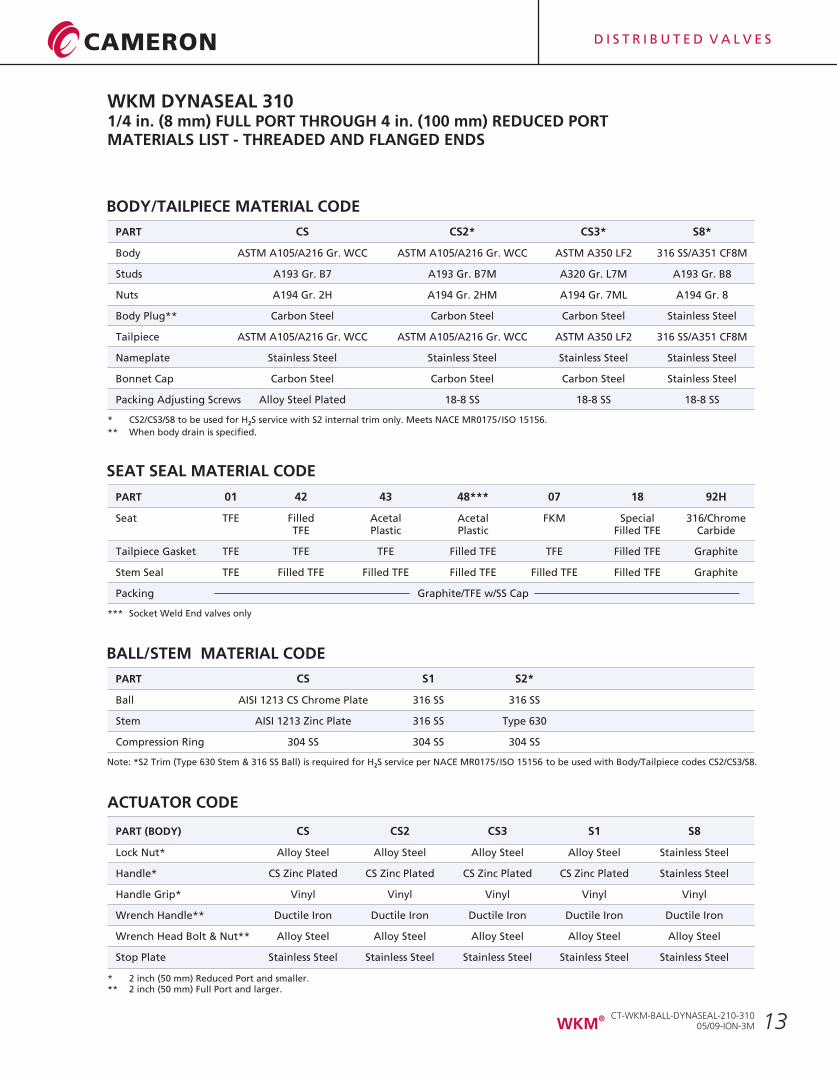
BODY/TAILPIECE MATERIAL CODE
PART CS CS2* CS3* S8*
Body ASTM A105/A216 Gr. WCC
Studs A193 Gr. B7 A193 Gr. B7M A320 Gr. L7M A193 Gr. B8
Nuts A194 Gr. 2H A194 Gr. 2HM A194 Gr. 7ML A194 Gr. 8
Body Plug** Carbon Steel Carbon Steel Carbon Steel Stainless Steel
Tailpiece ASTM A105/A216 Gr. WCC ASTM A105/A216 Gr. WCC ASTM A350 LF2 316 SS/A351 CF8M
Nameplate Stainless Steel Stainless Steel Stainless Steel Stainless Steel
Bonnet Cap Carbon Steel Carbon Steel Carbon Steel Stainless Steel
Packing Adjusting Screws Alloy Steel Plated 18-8 SS 18-8 SS 18-8 SS
ASTM A105/A216 Gr. WCC ASTM A350 LF2 316 SS/A351 CF8M
WKM DYNASEAL 3101/4 in. (8 mm) FULL PORT THROUGH 4 in. (100 mm) REDUCED PORTMATERIALS LIST - THREADED AND FLANGED ENDS
SEAT SEAL MATERIAL CODE
PART 01 42 43 48*** 07 18 92H
Seat TFE Filled Acetal Acetal FKM Special 316/ChromeTFE Plastic Plastic Filled TFE Carbide
Tailpiece Gasket TFE TFE TFE Filled TFE TFE Filled TFE Graphite
Stem Seal TFE Filled TFE
Packing Graphite/TFE w/SS Cap
Filled TFE Filled TFE Filled TFE Filled TFE Graphite
BALL/STEM MATERIAL CODE
PART CS S1 S2*
Ball AISI 1213 CS Chrome Plate 316 SS 316 SS
Stem AISI 1213 Zinc Plate 316 SS Type 630
Compression Ring 304 SS 304 SS 304 SS
ACTUATOR CODE
PART (BODY) CS CS2 CS3 S1 S8
Lock Nut* Alloy Steel Alloy Steel Alloy Steel Alloy Steel Stainless Steel
Handle* CS Zinc Plated CS Zinc Plated CS Zinc Plated CS Zinc Plated Stainless Steel
Handle Grip* Vinyl Vinyl Vinyl Vinyl Vinyl
Wrench Handle** Ductile Iron Ductile Iron Ductile Iron Ductile Iron Ductile Iron
Wrench Head Bolt & Nut** Alloy Steel Alloy Steel Alloy Steel Alloy Steel Alloy Steel
Stop Plate Stainless Steel Stainless Steel Stainless Steel Stainless Steel Stainless Steel
* CS2/CS3/S8 to be used for H S service with S2 internal trim only. Meets NACE 2
** When body drain is specified.
MR0175/ISO 15156.
*** Socket Weld End valves only
Note: *S2 Trim (Type 630 Stem & 316 SS Ball) is required for H S service per NACE to be used with Body/Tailpiece codes CS2/CS3/S8.2 MR0175/ISO 15156
* 2 inch (50 mm) Reduced Port and smaller.** 2 inch (50 mm) Full Port and larger.
CT-WKM-BALL-DYNASEAL-210-31005/09-ION-3M
®WKM
D I S T R I B U T E D V A L V E S
14
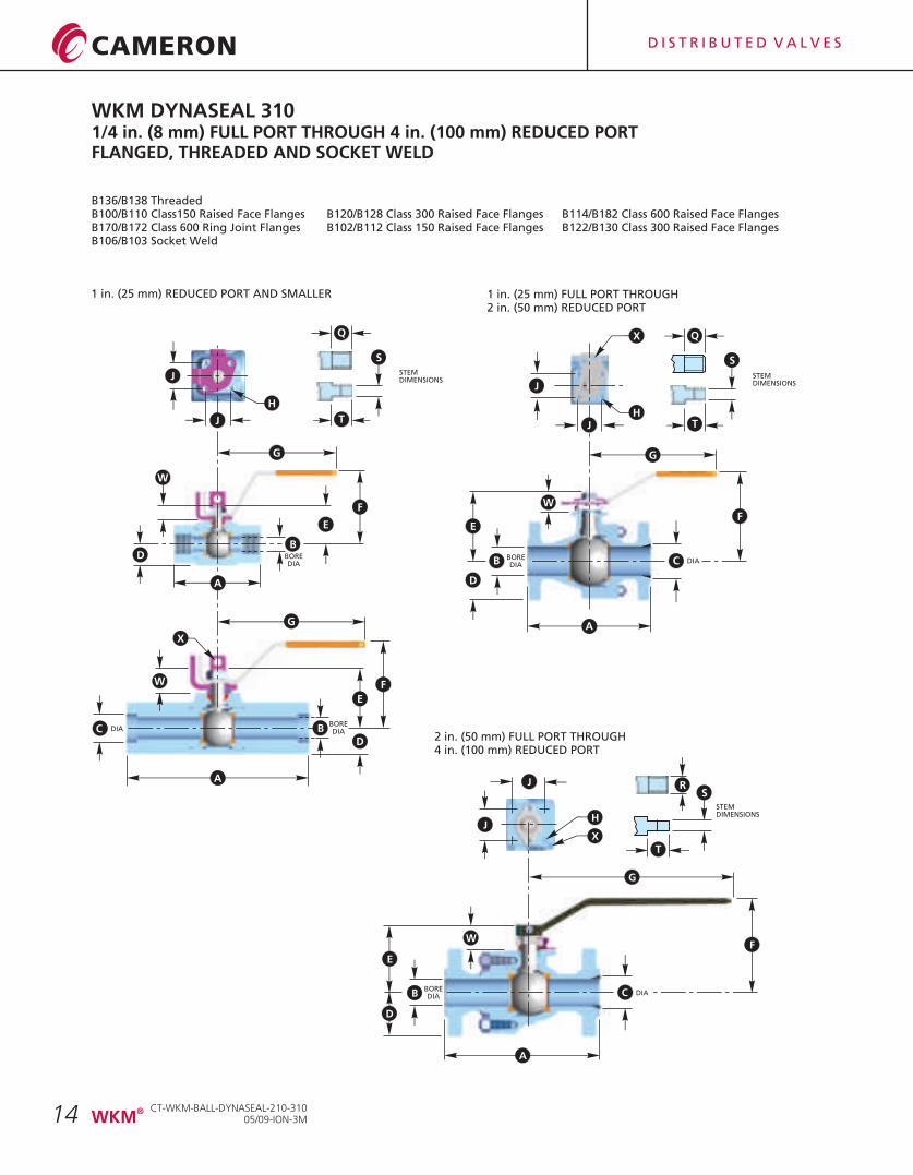
WKM DYNASEAL 3101/4 in. (8 mm) FULL PORT THROUGH 4 in. (100 mm) REDUCED PORTFLANGED, THREADED AND SOCKET WELD
B136/B138 ThreadedB100/B110 Class150 Raised Face Flanges B120/B128 Class 300 Raised Face Flanges B114/B182 Class 600 Raised Face FlangesB170/B172 Class 600 Ring Joint Flanges B102/B112 Class 150 Raised Face Flanges B122/B130 Class 300 Raised Face FlangesB106/B103 Socket Weld
BOREDIA
1 in. (25 mm) FULL PORT THROUGH2 in. (50 mm) REDUCED PORT
1 in. (25 mm) REDUCED PORT AND SMALLER
DIABOREDIA
J
J
H
G
G
A
F
E
D
W
C B
A
J
JH
X
G
W
E
D
A
B CBOREDIA
B
F
Q
S
T
STEMDIMENSIONS
Q
S
T
STEMDIMENSIONS
X
W
XJ
J
H
DIA
2 in. (50 mm) FULL PORT THROUGH4 in. (100 mm) REDUCED PORT
BOREDIA
G
FW
E
B
A
C
D
S
T
STEMDIMENSIONS
R
DIA
F
D
E
CT-WKM-BALL-DYNASEAL-210-31005/09-ION-3M
®WKM
D I S T R I B U T E D V A L V E S
15
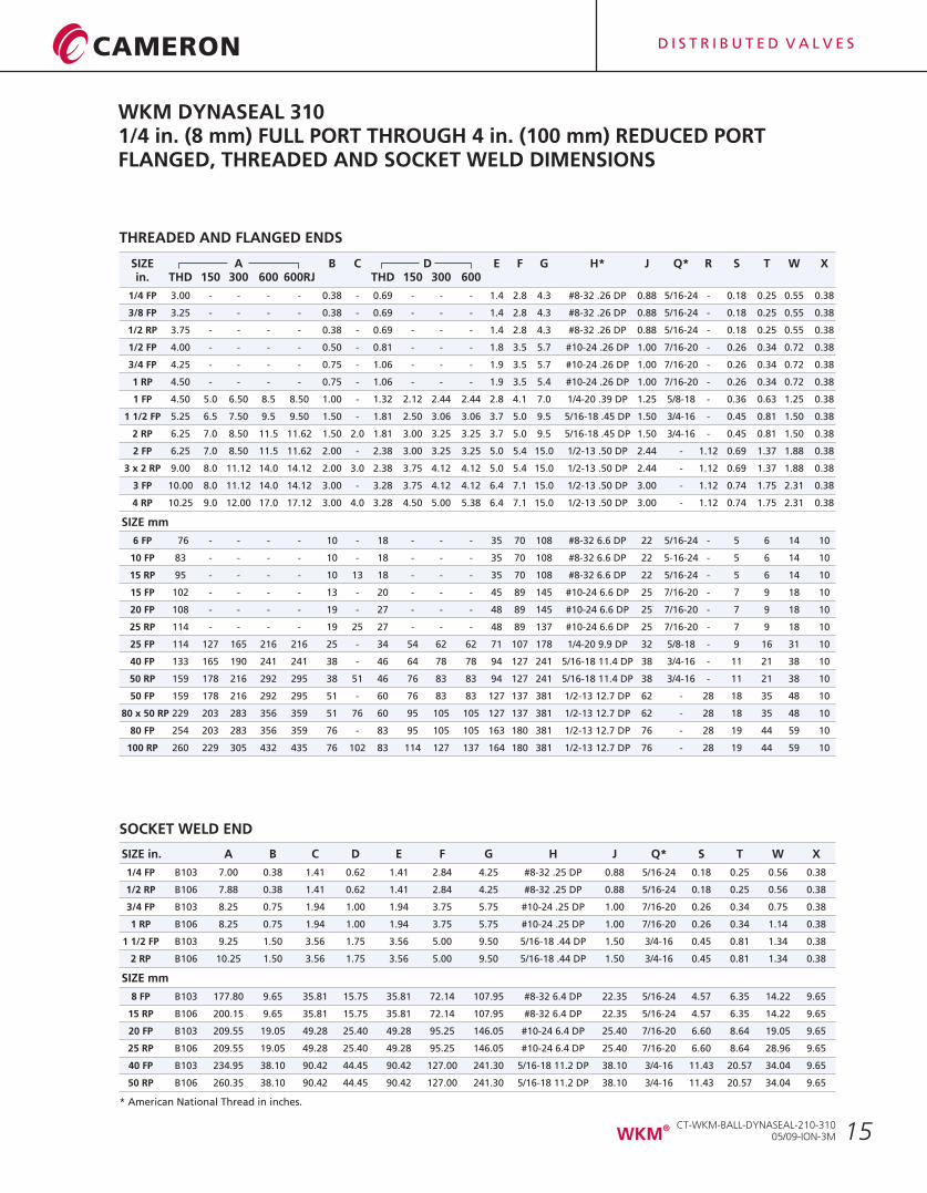
WKM DYNASEAL 3101/4 in. (8 mm) FULL PORT THROUGH 4 in. (100 mm) REDUCED PORTFLANGED, THREADED AND SOCKET WELD DIMENSIONS
* American National Thread in inches.
SIZE A B C D E F G H* J Q* R S T W Xin. THD 150 300 600 600RJ THD 150 300 600
1/4 FP 3.00 - - - - 0.38 - 0.69 - - - 1.4 2.8 4.3 #8-32 .26 DP 0.88 5/16-24 - 0.18 0.25 0.55 0.38
3/8 FP 3.25 - - - - 0.38 - 0.69 - - - 1.4 2.8 4.3 #8-32 .26 DP 0.88 5/16-24 - 0.18 0.25 0.55 0.38
1/2 RP 3.75 - - - - 0.38 - 0.69 - - - 1.4 2.8 4.3 #8-32 .26 DP 0.88 5/16-24 - 0.18 0.25 0.55 0.38
1/2 FP 4.00 - - - - 0.50 - 0.81 - - - 1.8 3.5 5.7 #10-24 .26 DP 1.00 7/16-20 - 0.26 0.34 0.72 0.38
3/4 FP 4.25 - - - - 0.75 - 1.06 - - - 1.9 3.5 5.7 #10-24 .26 DP 1.00 7/16-20 - 0.26 0.34 0.72 0.38
1 RP 4.50 - - - - 0.75 - 1.06 - - - 1.9 3.5 5.4 #10-24 .26 DP 1.00 7/16-20 - 0.26 0.34 0.72 0.38
1 FP 4.50 5.0 6.50 8.5 8.50 1.00 - 1.32 2.12 2.44 2.44 2.8 4.1 7.0 1/4-20 .39 DP 1.25 5/8-18 - 0.36 0.63 1.25 0.38
1 1/2 FP 5.25 6.5 7.50 9.5 9.50 1.50 - 1.81 2.50 3.06 3.06 3.7 5.0 9.5 5/16-18 .45 DP 1.50 3/4-16 - 0.45 0.81 1.50 0.38
2 RP 6.25 7.0 8.50 11.5 11.62 1.50 2.0 1.81 3.00 3.25 3.25 3.7 5.0 9.5 5/16-18 .45 DP 1.50 3/4-16 - 0.45 0.81 1.50 0.38
2 FP 6.25 7.0 8.50 11.5 11.62 2.00 - 2.38 3.00 3.25 3.25 5.0 5.4 15.0 1/2-13 .50 DP 2.44 - 1.12 0.69 1.37 1.88 0.38
3 x 2 RP 9.00 8.0 11.12 14.0 14.12 2.00 3.0 2.38 3.75 4.12 4.12 5.0 5.4 15.0 1/2-13 .50 DP 2.44 - 1.12 0.69 1.37 1.88 0.38
3 FP 10.00 8.0 11.12 14.0 14.12 3.00 - 3.28 3.75 4.12 4.12 6.4 7.1 15.0 1/2-13 .50 DP 3.00 - 1.12 0.74 1.75 2.31 0.38
4 RP 10.25 9.0 12.00 17.0 17.12 3.00 4.0 3.28 4.50 5.00 5.38 6.4 7.1 15.0 1/2-13 .50 DP 3.00 - 1.12 0.74 1.75 2.31 0.38
SIZE mm
6 FP 76 - - - - 10 - 18 - - - 35 70 108 #8-32 6.6 DP 22 5/16-24 - 5 6 14 10
10 FP 83 - - - - 10 - 18 - - - 35 70 108 #8-32 6.6 DP 22 5-16-24 - 5 6 14 10
15 RP 95 - - - - 10 13 18 - - - 35 70 108 #8-32 6.6 DP 22 5/16-24 - 5 6 14 10
15 FP 102 - - - - 13 - 20 - - - 45 89 145 #10-24 6.6 DP 25 7/16-20 - 7 9 18 10
20 FP 108 - - - - 19 - 27 - - - 48 89 145 #10-24 6.6 DP 25 7/16-20 - 7 9 18 10
25 RP 114 - - - - 19 25 27 - - - 48 89 137 #10-24 6.6 DP 25 7/16-20 - 7 9 18 10
25 FP 114 127 165 216 216 25 - 34 54 62 62 71 107 178 1/4-20 9.9 DP 32 5/8-18 - 9 16 31 10
40 FP 133 165 190 241 241 38 - 46 64 78 78 94 127 241 5/16-18 11.4 DP 38 3/4-16 - 11 21 38 10
50 RP 159 178 216 292 295 38 51 46 76 83 83 94 127 241 5/16-18 11.4 DP 38 3/4-16 - 11 21 38 10
50 FP 159 178 216 292 295 51 - 60 76 83 83 127 137 381 1/2-13 12.7 DP 62 - 28 18 35 48 10
80 x 50 RP 229 203 283 356 359 51 76 60 95 105 105 127 137 381 1/2-13 12.7 DP 62 - 28 18 35 48 10
80 FP 254 203 283 356 359 76 - 83 95 105 105 163 180 381 1/2-13 12.7 DP 76 - 28 19 44 59 10
100 RP 260 229 305 432 435 76 102 83 114 127 137 164 180 381 1/2-13 12.7 DP 76 - 28 19 44 59 10
SOCKET WELD END
SIZE in. A B C D E F G H J Q* S T W X
1/4 FP B103 7.00 0.38 1.41 0.62 1.41 2.84 4.25 #8-32 .25 DP 0.88 5/16-24 0.18 0.25 0.56 0.38
1/2 RP B106 7.88 0.38 1.41 0.62 1.41 2.84 4.25 #8-32 .25 DP 0.88 5/16-24 0.18 0.25 0.56 0.38
3/4 FP B103 8.25 0.75 1.94 1.00 1.94 3.75 5.75 #10-24 .25 DP 1.00 7/16-20 0.26 0.34 0.75 0.38
1 RP B106 8.25 0.75 1.94 1.00 1.94 3.75 5.75 #10-24 .25 DP 1.00 7/16-20 0.26 0.34 1.14 0.38
1 1/2 FP B103 9.25 1.50 3.56 1.75 3.56 5.00 9.50 5/16-18 .44 DP 1.50 3/4-16 0.45 0.81 1.34 0.38
2 RP B106 10.25 1.50 3.56 1.75 3.56 5.00 9.50 5/16-18 .44 DP 1.50 3/4-16 0.45 0.81 1.34 0.38
SIZE mm
8 FP B103 177.80 9.65 35.81 15.75 35.81 72.14 107.95 #8-32 6.4 DP 22.35 5/16-24 4.57 6.35 14.22 9.65
15 RP B106 200.15 9.65 35.81 15.75 35.81 72.14 107.95 #8-32 6.4 DP 22.35 5/16-24 4.57 6.35 14.22 9.65
20 FP B103 209.55 19.05 49.28 25.40 49.28 95.25 146.05 #10-24 6.4 DP 25.40 7/16-20 6.60 8.64 19.05 9.65
25 RP B106 209.55 19.05 49.28 25.40 49.28 95.25 146.05 #10-24 6.4 DP 25.40 7/16-20 6.60 8.64 28.96 9.65
40 FP B103 234.95 38.10 90.42 44.45 90.42 127.00 241.30 5/16-18 11.2 DP 38.10 3/4-16 11.43 20.57 34.04 9.65
50 RP B106 260.35 38.10 90.42 44.45 90.42 127.00 241.30 5/16-18 11.2 DP 38.10 3/4-16 11.43 20.57 34.04 9.65
THREADED AND FLANGED ENDS
CT-WKM-BALL-DYNASEAL-210-31005/09-ION-3M
®WKM
D I S T R I B U T E D V A L V E S
16
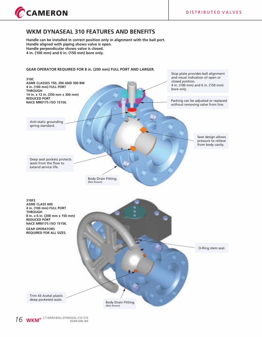
WKM DYNASEAL 310 FEATURES AND BENEFITS
Stop plate provides ball alignmentand visual indication of open orclosed position.4 in. (100 mm) and 6 in. (150 mm)bore only.
Handle can be installed in correct position only in alignment with the ball port.Handle aligned with piping shows valve is open.Handle perpendicular shows valve is closed.4 in. (100 mm) and 6 in. (150 mm) bore only.
Packing can be adjusted or replacedwithout removing valve from line.
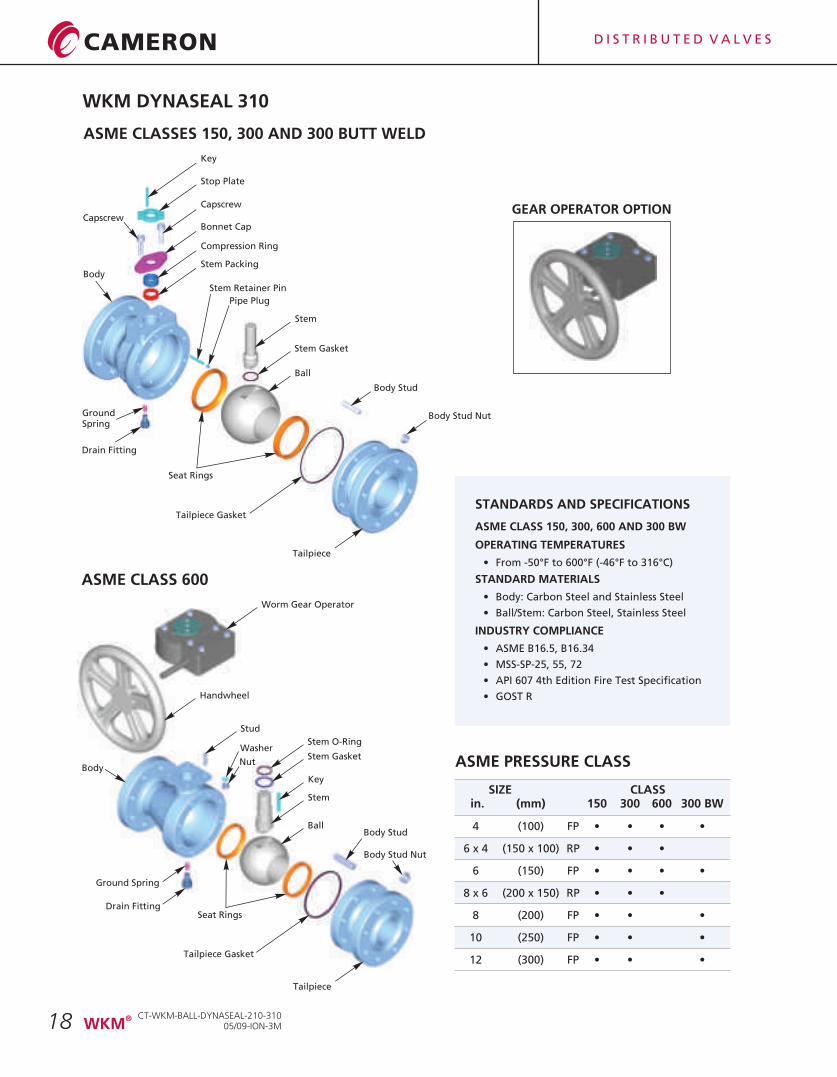
310CASME CLASSES 150, 300 AND 300 BW4 in. (100 mm) FULL PORTTHROUGH14 in. x 12 in. (350 mm x 300 mm)REDUCED PORTNACE MR0175/ISO 15156.
310F2ASME CLASS 6004 in. (100 mm) FULL PORTTHROUGH8 in. x 6 in. (200 mm x 150 mm)REDUCED PORTNACE
GEAR OPERATORSREQUIRED FOR ALL SIZES.
MR0175/ISO 15156.
GEAR OPERATOR REQUIRED FOR 8 in. (200 mm) FULL PORT AND LARGER.
Deep seat pockets protectsseats from the flow toextend service life.
Trim 43 Acetal plasticdeep pocketed seats.
Body Drain Fitting.(Not shown)
O-Ring stem seal.
Body Drain Fitting.(Not shown)
Seat design allowspressure to relievefrom body cavity.
CT-WKM-BALL-DYNASEAL-210-31005/09-ION-3M
®WKM
Anti-static groundingspring standard.
D I S T R I B U T E D V A L V E S
17
WKM DynaSeal 310 Ball Valves satisfy a wide range of applications. Available in a variety of standard and optional materials, they may be specified in sizes from 4 in. (100 mm) to 14 in. (350 mm) and ASME Class 150 and 300. ASME Class 600 is available in sizes 4 in. (100 mm) through 8 in. x 6 in. (200 mm x 150 mm). Engineered for heavy duty, maintenance free performance, the WKM DynaSeal 310 Ball Valve is commonly selected for a variety of applications in virtually any industry.
WKM DynaSeal 310 Ball Valve is the workhorse of the refining industry.
HIGH TEMPERATURE SERVICESpecial high temperature trims are available for WKM DynaSeal 310 Ball Valves which provide for service to 600°F (316°C). This trim is excellent for steam service, hot oil, heat transfer fluids, boiler feed water and similar applications.
LOW TEMPERATURE SERVICEStandard trims accommodate temperatures to -20°F (-29°C).For temperatures to -50°F (-46°C);please consult factory.
MAINTENANCE FREE PERFORMANCEUnder most conditions, the WKM DynaSeal 310 Ball Valve will provide years of trouble free service with no maintenance required.In some severe applications, such as handling extremely abrasive slurries at high temperature, it may be necessary to replace the seats occasionally.Seat and seal kits are available and replacement can be done easily with ordinary tools.
SOUR OIL AND GAS SERVICEWKM DynaSeal 310 Ball Valves have served for years in gathering lines, manifolds and field processing units in sour oil and gas fields. They can be trimmed to conform with NACE MR0175/ISO 15156.
CHEMICAL & PETROCHEMICAL PLANTSThe list of chemical and petrochemical applications for WKM DynaSeal 310 Ball Valves is limitless. They are serving in many plastic plants handling such slurries as 40% vinyl chloride, in high pressure catalyst lines and in processes handling dry lading such as polyethylene and polystyrene powders.There are hundreds of applications in such plants where WKM DynaSeal 310 Ball Valves are providing efficient service.
REFINING
The many metal seats, seals and available trims offer the versatility needed to handle the wide variety of products used in the refining process.
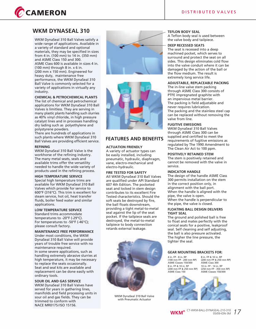
TEFLON BODY SEALA Teflon body seal is used between the valve body and tailpiece.
DEEP RECESSED SEATS The seat is recessed into a deep machined pocket, which serves to surround and protect the seat on all sides. This design eliminates cold flow into the valve conduit where it can be damaged by the action of the ball or the flow medium. The result is extremely long service life.
ADJUSTABLE, REPLACEABLE PACKINGThe in-line valve stem packing through ASME Class 300 consists of PTFE impregnated graphite with an impervious metal barrier. The packing is field adjustable and never requires lubrication.The packing and the stainless steel cap can be replaced without removing the valve from line.
FUGITIVE EMISSIONSWKM DynaSeal 310 Ball Valves through ASME Class 300 can be supplied and certified to meet the requirements of fugitive emissions as regulated by The 1990 Amendment to The Clean Air Act to 100 ppm.
POSITIVELY RETAINED STEMThe stem is positively retained and cannot be removed with the valve in service.
INDICATOR HANDLEThe design of the handle ASME Class 300 permits installation on the stem in the correct position only, in alignment with the ball port.When the handle is aligned with the pipe, the valve is open.When the handle is perpendicular to the pipe, the valve is closed.
FLOATING BALL DESIGN DELIVERS TIGHT SEALThe ground and polished ball is freeto float and mates perfectly with the conical seats for a positive, leakproof seal. Self cleaning and self adjusting, the ball is also pressure activated.The higher the line pressure, the tighter the seal.
ACTUATION FRIENDLYA variety of actuator types can be easily installed, includingpneumatic, hydraulic, diaphragm, vane, electro-mechanical andelectro-hydraulic.
FIRE TESTED FOR SAFETYAll WKM DynaSeal 310 Ball Valves are qualified under API Standard 607 4th Edition. The pocketed seat and locked in stem design contributes to its excellent Fire Tested characteristics. Should the soft seats be destroyed by fire, the ball floats downstream, providing a tight metal-to-metal seal against the lip of the seat pocket. If the tailpiece seals are destroyed, the metal-to-metal tailpiece to body connection retards external leakage.
WKM DynaSeal 310 Ball Valvewith Pneumatic Actuator
GEAR MOUNTING BRACKETS FOR:
4 in. FP - 8 in. RP(100 mm FP - 200 mm RP)ASME Classes 150/300
8 in. FP & 10 in. RP(200 mm FP & 250 mm RP)ASME Class 150
8 in. FP & 10 in. RP(200 mm FP & 250 mm RP)ASME Class 300
10 in. FP - 14 in. RP(250 mm FP - 350 mm RP)ASME Classes 150/300
FEATURES AND BENEFITS
WKM DYNASEAL 310
CT-WKM-BALL-DYNASEAL-210-31005/09-ION-3M
®WKM
D I S T R I B U T E D V A L V E S
18
ASME PRESSURE CLASS
SIZE CLASS in. (mm) 150 300 600 300 BW
4 (100) FP • • • •
6 x 4 (150 x 100) RP • • •
6 (150) FP • • • •
8 x 6 (200 x 150) RP • • •
8 (200) FP • • •
10 (250) FP • • •
12 (300) FP • • •
WKM DYNASEAL 310
STANDARDS AND SPECIFICATIONS
ASME CLASS 150, 300, 600 AND 300 BW
OPERATING TEMPERATURES
• From -50°F to 600°F (-46°F to 316°C)
STANDARD MATERIALS
• Body: Carbon Steel and Stainless Steel
• Ball/Stem: Carbon Steel, Stainless Steel
INDUSTRY COMPLIANCE
• ASME B16.5, B16.34
• MSS-SP-25, 55, 72
• API 607 4th Edition Fire Test Specification
• GOST R
Ball
GEAR OPERATOR OPTION
ASME CLASS 600
Stem Gasket
Stem
Body Stud
Body Stud Nut
Tailpiece Gasket
Tailpiece
Stem Retainer Pin
Pipe Plug
Stem Packing
Compression Ring
Bonnet Cap
Capscrew
Stop Plate
Key
Body
Ball
Stem Gasket
Stem
Body Stud
Body Stud Nut
Seat Rings
Tailpiece Gasket
Tailpiece
Stem O-Ring
Stud
Key
Washer
NutBody
Handwheel
Worm Gear Operator
Ground Spring
Drain Fitting
Seat Rings
GroundSpring
Drain Fitting
ASME CLASSES 150, 300 AND 300 BUTT WELD
Capscrew
CT-WKM-BALL-DYNASEAL-210-31005/09-ION-3M
®WKM
D I S T R I B U T E D V A L V E S
19
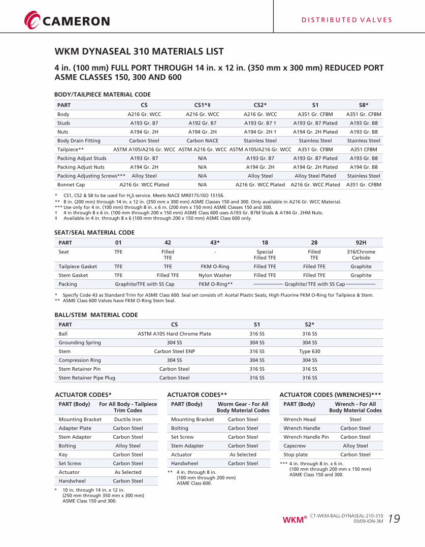
BODY/TAILPIECE MATERIAL CODE
PART CS CS1*‡ CS2* S1 S8*
Body A216 Gr. WCC A216 Gr. WCC
Studs A193 Gr. B7 A192 Gr. B7 A193 Gr. B7 † A193 Gr. B7 Plated A193 Gr. B8
Nuts A194 Gr. 2H A194 Gr. 2H A194 Gr. 2H † A194 Gr. 2H Plated A193 Gr. B8
Body Drain Fitting Carbon Steel Carbon NACE Stainless Steel Stainless Steel Stainless Steel
Tailpiece** ASTM A105/A216 Gr. WCC ASTM A216 Gr. WCC ASTM A105/A216 Gr. WCC A351 Gr. CF8M A351 CF8M
Packing Adjust Studs A193 Gr. B7 N/A A193 Gr. B7 A193 Gr. B7 Plated A193 Gr. B8
Packing Adjust Nuts A194 Gr. 2H N/A A194 Gr. 2H A194 Gr. 2H Plated A194 Gr. B8
Packing Adjusting Screws*** Alloy Steel N/A Alloy Steel Alloy Steel Plated Stainless Steel
Bonnet Cap A216 Gr. WCC Plated N/A A216 Gr. WCC Plated A216 Gr. WCC Plated A351 Gr. CF8M
A216 Gr. WCC A351 Gr. CF8M A351 Gr. CF8M
* CS1, CS2 & S8 to be used for H S service. Meets NACE MR0175/ISO 15156.2
** 8 in. (200 mm) through 14 in. x 12 in. (350 mm x 300 mm) ASME Classes 150 and 300. Only available in A216 Gr. WCC Material.*** Use only for 4 in. (100 mm) through 8 in. x 6 in. (200 mm x 150 mm) ASME Classes 150 and 300.† 4 in through 8 x 6 in. (100 mm through 200 x 150 mm) ASME Class 600 uses A193 Gr. B7M Studs & A194 Gr. 2HM Nuts.‡ Available in 4 in. through 8 x 6 (100 mm through 200 x 150 mm) ASME Class 600 only.
WKM DYNASEAL 310 MATERIALS LIST
SEAT/SEAL MATERIAL CODE
PART 01 42 43* 18 28 92H
Seat TFE Filled - Special Filled 316/ChromeTFE Filled TFE TFE Carbide
Tailpiece Gasket TFE TFE FKM O-Ring Filled TFE Filled TFE Graphite
Stem Gasket TFE Filled TFE Nylon Washer Filled TFE Filled TFE Graphite
Packing Graphite/TFE with SS Cap FKM O-Ring** Graphite/ TFE with SS Cap
BALL/STEM MATERIAL CODE
PART CS S1 S2*
Ball ASTM A105 Hard Chrome Plate 316 SS 316 SS
Grounding Spring 304 SS 304 SS 304 SS
Stem Carbon Steel ENP 316 SS Type 630
Compression Ring 304 SS 304 SS 304 SS
Stem Retainer Pin Carbon Steel 316 SS 316 SS
Stem Retainer Pipe Plug Carbon Steel 316 SS 316 SS
* Specify Code 43 as Standard Trim for ASME Class 600. Seal set consists of: Acetal Plastic Seats, High Fluorine FKM O-Ring for Tailpiece & Stem.** ASME Class 600 Valves have FKM O-Ring Stem Seal.
ACTUATOR CODES*
PART (Body) For All Body - Tailpiece Trim Codes
Mounting Bracket Ductile Iron
Adapter Plate Carbon Steel
Stem Adapter Carbon Steel
Bolting Alloy Steel
Key Carbon Steel
Set Screw Carbon Steel
Actuator As Selected
Handwheel Carbon Steel
ACTUATOR CODES** ACTUATOR CODES (WRENCHES)***
* 10 in. through 14 in. x 12 in.(250 mm through 350 mm x 300 mm)ASME Class 150 and 300.
** 4 in. through 8 in.(100 mm through 200 mm)ASME Class 600.
*** 4 in. through 8 in. x 6 in.(100 mm through 200 mm x 150 mm)ASME Class 150 and 300.
PART (Body) Worm Gear - For AllBody Material Codes
Mounting Bracket Carbon Steel
Bolting Carbon Steel
Set Screw Carbon Steel
Stem Adapter Carbon Steel
Actuator As Selected
Handwheel Carbon Steel
PART (Body) Wrench - For AllBody Material Codes
Wrench Head Steel
Wrench Handle Carbon Steel
Wrench Handle Pin Carbon Steel
Capscrew Alloy Steel
Stop plate Carbon Steel
4 in. (100 mm) FULL PORT THROUGH 14 in. x 12 in. (350 mm x 300 mm) REDUCED PORTASME CLASSES 150, 300 AND 600
CT-WKM-BALL-DYNASEAL-210-31005/09-ION-3M
®WKM
D I S T R I B U T E D V A L V E S
20
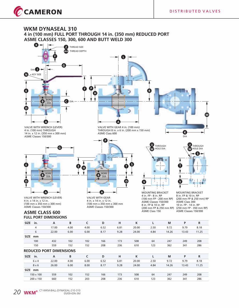
4 in (100 mm) FULL PORT THROUGH 14 in. (350 mm) REDUCED PORTASME CLASSES 150, 300, 600 AND BUTT WELD 300
MOUNTING BRACKET4 in. FP - 8 in. RP(100 mm FP - 200 mm RP)ASME Classes 150/3008 in. FP & 10 in. RP(200 mm FP & 250 mm RP)ASME Class 150
FULL PORT DIMENSIONS
SIZE in. A B C D H K L M P R
4 17.00 4.00 4.00 6.52 6.81 20.00 2.50 9.72 9.79 8.18
6 22.00 6.00 6.00 8.17 9.28 24.00 4.84 14.26 13.43 11.25
SIZE mm
100 432 102 102 166 173 508 64 247 249 208
150 559 152 152 208 236 610 123 362 341 286
REDUCED PORT DIMENSIONS
ASME CLASS 600
SIZE in. A B C D H K L M P R
6 x 4 22.00 4.00 6.00 6.52 6.81 20.00 2.50 9.72 9.79 8.18
8 x 6 26.00 6.00 8.00 8.17 9.28 24.00 4.84 14.26 13.43 11.25
SIZE mm
150 x 100 559 102 152 166 173 508 64 247 249 208
200 x 150 660 152 203 208 236 610 123 362 341 286
VALVE WITH GEAR 4 in. (100 mm)THROUGH 8 in. x 6 in. (200 mm x 150 mm)ASME Class 600
BORE
DIA
Z THREAD SIZE
D
F
DIA
DIA
B C
E
= KEY SIZE
HR
P
DIA
M
AA THREAD DEPTH
VALVE WITH WRENCH (LEVER)4 in. (100 mm) THROUGH14 in. x 12 in. (350 mm x 300 mm)ASME Classes 150/300
D
E
VALVE WITH WRENCH (LEVER)4 in. x 14 in. x 12 in.(100 mm x 350 mm x 300 mm)ASME Classes 150/300
BORE
DIAB
HE
BORE
DIAB
VALVE WITH GEAR4 in. x 14 in. x 12 in.(100 mm x 350 mm x 300 mmASME Classes 150/300
V V
T
THROUGHHOLE DIA
THROUGHHOLE DIA
U
W
K
L
AA
N
J
G
X
Y
A A
G
P
S
ST
D
MOUNTING BRACKET8 in. FP & 10 in. RP (200 mm FP & 250 mm) RPASME Class 30010 in. FP - 14 in. RP(250 mm FP - 350 mm RP)ASME Classes 150/300
U
W
WKM DYNASEAL 310
CT-WKM-BALL-DYNASEAL-210-31005/09-ION-3M
®WKM
D I S T R I B U T E D V A L V E S
21
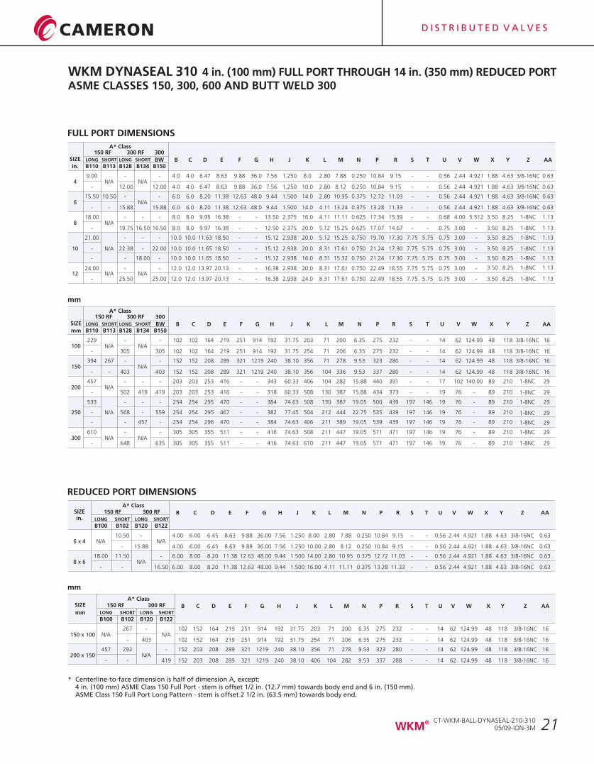
* Centerline-to-face dimension is half of dimension A, except:4 in. (100 mm) ASME Class 150 Full Port - stem is offset 1/2 in. (12.7 mm) towards body end and 6 in. (150 mm). ASME Class 150 Full Port Long Pattern - stem is offset 2 1/2 in. (63.5 mm) towards body end.
FULL PORT DIMENSIONS
WKM DYNASEAL 310 4 in. (100 mm) FULL PORT THROUGH 14 in. (350 mm) REDUCED PORTASME CLASSES 150, 300, 600 AND BUTT WELD 300
REDUCED PORT DIMENSIONS
mm
mm
A* ClassSIZE 150 RF 300 RF B C D E F G H J K L M N P R S T U V W X Y Z AAin. LONG SHORT LONG SHORT
B100 B102 B120 B122
10.50 - 4.00 6.00 6.45 8.63 9.88 36.00 7.56 1.250 8.00 2.80 7.88 0.250 10.84 9.15 - - 0.56 2.44 4.921 1.88 4.63 3/8-16NC 0.636 x 4 N/A N/A
- 15.88 4.00 6.00 6.45 8.63 9.88 36.00 7.56 1.250 10.00 2.80 8.12 0.250 10.84 9.15 - - 0.56 2.44 4.921 1.88 4.63 3/8-16NC 0.63
18.00 11.50 - 6.00 8.00 8.20 11.38 12.63 48.00 9.44 1.500 14.00 2.80 10.95 0.375 12.72 11.03 - - 0.56 2.44 4.921 1.88 4.63 3/8-16NC 0.638 x 6 N/A
- - 16.50 6.00 8.00 8.20 11.38 12.63 48.00 9.44 1.500 16.00 4.11 11.11 0.375 13.28 11.33 - - 0.56 2.44 4.921 1.88 4.63 3/8-16NC 0.63
A* ClassSIZE 150 RF 300 RF B C D E F G H J K L M N P R S T U V W X Y Z AA
LONG SHORT LONG SHORTmmB100 B102 B120 B122
267 - 102 152 164 219 251 914 192 31.75 203 71 200 6.35 275 232 - - 14 62 124.99 48 118 3/8-16NC 16150 x 100 N/A N/A
- 403 102 152 164 219 251 914 192 31.75 254 71 206 6.35 275 232 - - 14 62 124.99 48 118 3/8-16NC 16
457 292 - 152 203 208 289 321 1219 240 38.10 356 71 278 9.53 323 280 - - 14 62 124.99 48 118 3/8-16NC 16200 x 150 N/A
- - 419 152 203 208 289 321 1219 240 38.10 406 104 282 9.53 337 288 - - 14 62 124.99 48 118 3/8-16NC 16
A* Class 150 RF 300 RF 300
SIZE LONG SHORT LONG SHORT BW B C D E F G H J K L M N P R S T U V W X Y Z AAin. B110 B113 B128 B134 B150
9.00 - - 4.0 4.0 6.47 8.63 9.88 36.0 7.56 1.250 8.0 2.80 7.88 0.250 10.84 9.15 - - 0.56 2.44 4.921 1.88 4.63 3/8-16NC 0.634 N/A N/A
- 12.00 12.00 4.0 4.0 6.47 8.63 9.88 36.0 7.56 1.250 10.0 2.80 8.12 0.250 10.84 9.15 - - 0.56 2.44 4.921 1.88 4.63 3/8-16NC 0.63
15.50 10.50 - - 6.0 6.0 8.20 11.38 12.63 48.0 9.44 1.500 14.0 2.80 10.95 0.375 12.72 11.03 - - 0.56 2.44 4.921 1.88 4.63 3/8-16NC 0.636 N/A
- - 15.88 15.88 6.0 6.0 8.20 11.38 12.63 48.0 9.44 1.500 14.0 4.11 13.24 0.375 13.28 11.33 - - 0.56 2.44 4.921 1.88 4.63 3/8-16NC 0.63
18.00 - - - 8.0 8.0 9.95 16.38 - - 13.50 2.375 16.0 4.11 11.11 0.625 17.34 15.39 - - 0.68 4.00 5.512 3.50 8.25 1-8NC 1.138 N/A
- 19.75 16.50 16.50 8.0 8.0 9.97 16.38 - - 12.50 2.375 20.0 5.12 15.25 0.625 17.07 14.67 - - 0.75 3.00 - 3.50 8.25 1-8NC 1.13
21.00 - - - 10.0 10.0 11.63 18.50 - - 15.12 2.938 20.0 5.12 15.25 0.750 19.70 17.30 7.75 5.75 0.75 3.00 - 3.50 8.25 1-8NC 1.13
10 - N/A 22.38 - 22.00 10.0 10.0 11.65 18.50 - - 15.12 2.938 20.0 8.31 17.61 0.750 21.24 17.30 7.75 5.75 0.75 3.00 - 3.50 8.25 1-8NC 1.13
- - 18.00 - 10.0 10.0 11.65 18.50 - - 15.12 2.938 16.0 8.31 15.32 0.750 21.24 17.30 7.75 5.75 0.75 3.00 - 3.50 8.25 1-8NC 1.13
3.50 8.25 1-8NC 1.1324.00 - - 12.0 12.0 13.97 20.13 - - 16.38 2.938 20.0 8.31 17.61 0.750 22.49 18.55 7.75 5.75 0.75 3.00 -12 N/A N/A
- 25.50 25.00 12.0 12.0 13.97 20.13 - - 16.38 2.938 24.0 8.31 17.61 0.750 22.49 18.55 7.75 5.75 0.75 3.00 - 3.50 8.25 1-8NC 1.13
A* Class 150 RF 300 RF 300
SIZE LONG SHORT LONG SHORT BW B C D E F G H J K L M N P R S T U V W X Y Z AAmm B110 B113 B128 B134 B150
229 - - 102 102 164 219 251 914 192 31.75 203 71 200 6.35 275 232 - - 14 62 124.99 48 118 3/8-16NC 16100 N/A N/A
- 305 305 102 102 164 219 251 914 192 31.75 254 71 206 6.35 275 232 - - 14 62 124.99 48 118 3/8-16NC 16
394 267 - - 152 152 208 289 321 1219 240 38.10 356 71 278 9.53 323 280 - - 14 62 124.99 48 118 3/8-16NC 16150 N/A
- - 403 403 152 152 208 289 321 1219 240 38.10 356 104 336 9.53 337 280 - - 14 62 124.99 48 118 3/8-16NC 16
457 - - - 203 203 253 416 - - 343 60.33 406 104 282 15.88 440 391 - - 17 102 140.00 89 210 1-8NC 29200 N/A
- 502 419 419 203 203 253 416 - - 318 60.33 508 130 387 15.88 434 373 - - 19 76 - 89 210 1-8NC 29
533 - - - 254 254 295 470 - - 384 74.63 508 130 387 19.05 500 439 197 146 19 76 - 89 210 1-8NC 29
250 - N/A 568 - 559 254 254 295 467 - - 382 77.45 504 212 444 22.75 535 439 197 146 19 76 - 89 210 1-8NC 29
- - 457 - 254 254 296 470 - - 384 74.63 406 211 389 19.05 539 439 197 146 19 76 - 89 210 1-8NC 29
610 - - 305 305 355 511 - - 416 74.63 508 211 447 19.05 571 471 197 146 19 76 - 89 210 1-8NC 29300 N/A N/A
- 648 635 305 305 355 511 - - 416 74.63 610 211 447 19.05 571 471 197 146 19 76 - 89 210 1-8NC 29
CT-WKM-BALL-DYNASEAL-210-31005/09-ION-3M
®WKM
D I S T R I B U T E D V A L V E S
22
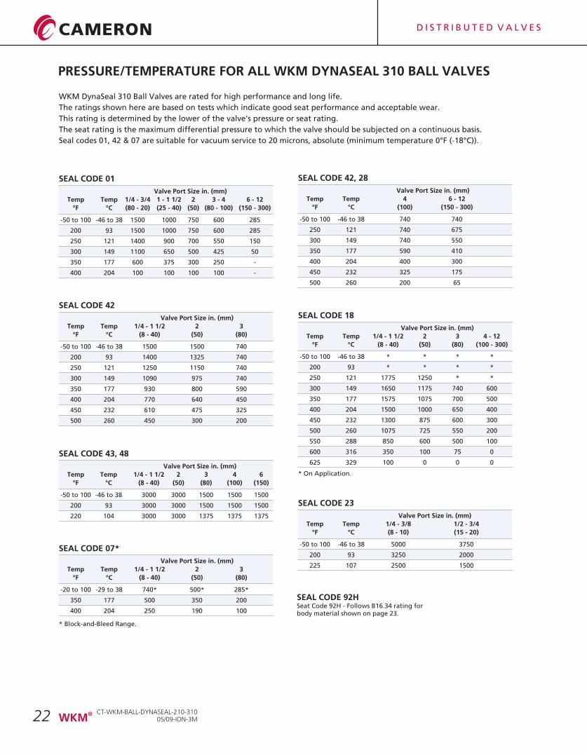
PRESSURE/TEMPERATURE FOR ALL WKM DYNASEAL 310 BALL VALVES
WKM DynaSeal 310 Ball Valves are rated for high performance and long life.
The ratings shown here are based on tests which indicate good seat performance and acceptable wear.
This rating is determined by the lower of the valve's pressure or seat rating.
The seat rating is the maximum differential pressure to which the valve should be subjected on a continuous basis.
Seal codes 01, 42 & 07 are suitable for vacuum service to 20 microns, absolute (minimum temperature 0°F (-18°C)).
SEAL CODE 01
Valve Port Size in. (mm)
Temp Temp 1/4 - 3/4 1 - 1 1/2 2 3 - 4 6 - 12
°F °C (80 - 20) (25 - 40) (50) (80 - 100) (150 - 300)
-50 to 100 -46 to 38 1500 1000 750 600 285
200 93 1500 1000 750 600 285
250 121 1400 900 700 550 150
300 149 1100 650 500 425 50
350 177 600 375 300 250 -
400 204 100 100 100 100 -
SEAL CODE 42
Valve Port Size in. (mm)
Temp Temp 1/4 - 1 1/2 2 3
°F °C (8 - 40) (50) (80)
-50 to 100 -46 to 38 1500 1500 740
200 93 1400 1325 740
250 121 1250 1150 740
300 149 1090 975 740
350 177 930 800 590
400 204 770 640 450
450 232 610 475 325
500 260 450 300 200
SEAL CODE 43, 48
Valve Port Size in. (mm)
Temp Temp 1/4 - 1 1/2 2 3 4 6
°F °C (8 - 40) (50) (80) (100) (150)
-50 to 100 -46 to 38 3000 3000 1500 1500 1500
200 93 3000 3000 1500 1500 1500
220 104 3000 3000 1375 1375 1375
SEAL CODE 07*
Valve Port Size in. (mm)
Temp Temp 1/4 - 1 1/2 2 3
°F °C (8 - 40) (50) (80)
-20 to 100 -29 to 38 740* 500* 285*
350 177 500 350 200
400 204 250 190 100
* Block-and-Bleed Range.
SEAL CODE 42, 28
Valve Port Size in. (mm)
Temp Temp 4 6 - 12
°F °C (100) (150 - 300)
-50 to 100 -46 to 38 740 740
250 121 740 675
300 149 740 550
350 177 590 410
400 204 400 300
450 232 325 175
500 260 200 65
SEAL CODE 18
Valve Port Size in. (mm)
Temp Temp 1/4 - 1 1/2 2 3 4 - 12
°F °C (8 - 40) (50) (80) (100 - 300)
-50 to 100 -46 to 38 * * * *
200 93 * * * *
250 121 1775 1250 * *
300 149 1650 1175 740 600
350 177 1575 1075 700 500
400 204 1500 1000 650 400
450 232 1300 875 600 300
500 260 1075 725 550 200
550 288 850 600 500 100
600 316 350 100 75 0
625 329 100 0 0 0
* On Application.
SEAL CODE 23
Valve Port Size in. (mm)
Temp Temp 1/4 - 3/8 1/2 - 3/4
°F °C (8 - 10) (15 - 20)
-50 to 100 -46 to 38 5000 3750
200 93 3250 2000
225 107 2500 1500
CT-WKM-BALL-DYNASEAL-210-31005/09-ION-3M
®WKM
SEAL CODE 92HSeat Code 92H - Follows B16.34 rating forbody material shown on page 23.
D I S T R I B U T E D V A L V E S
23
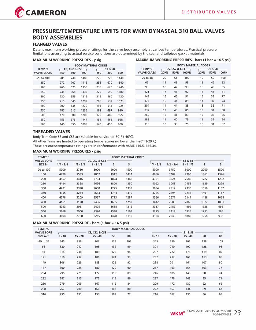
PRESSURE/TEMPERATURE LIMITS FOR WKM DYNASEAL 310 BALL VALVESBODY ASSEMBLIES FLANGED VALVESData is maximum working pressure ratings for the valve body assembly at various temperatures. Practical pressure limitations according to actual service conditions are determined by the seal and tailpiece gasket materials.
THREADED VALVESBody Trim Code S8 and CS3 are suitable for service to -50°F (-46°C).
All other Trims are limited to operating temperatures no lower than -20°F (-29°C)
These pressure/temperature ratings are in conformance with ASME B16.5, B16.34.
MAXIMUM WORKING PRESSURES - psig
BODY MATERIAL CODES
TEMP °F CS, CS2 & CS3 S1 & S8
VALVE CLASS 150 300 600 150 300 600
-20 to 100 285 740 1480 275 720 1440
150 272 707 1415 255 670 1340
200 260 675 1350 235 620 1240
250 245 665 1332 225 590 1180
300 230 655 1315 215 560 1120
350 215 645 1292 205 537 1073
400 200 635 1270 195 515 1025
450 185 617 1235 182 497 990
500 170 600 1200 170 480 955
550 155 575 1147 155 465 928
600 140 550 1095 140 450 900
MAXIMUM WORKING PRESSURES - bars (1 bar = 14.5 psi)
BODY MATERIAL CODES
TEMP °C CS, CS2 & CS3 S1 & S8
VALVE CLASS 20PN 50PN 100PN 20PN 50PN 100PN
-29 to 38 20 51 102 19 50 100
66 19 49 98 18 46 92
93 18 47 93 16 43 85
121 17 46 92 16 41 81
149 16 45 91 15 39 77
177 15 44 89 14 37 74
204 14 44 88 13 36 71
232 13 43 85 13 34 68
260 12 41 83 12 33 66
288 11 40 79 11 32 64
316 10 38 75 10 31 62
MAXIMUM WORKING PRESSURES - psig
TEMP °F BODY MATERIAL CODES
VALVE BORE CS, CS2 & CS3 S1 & S8
SIZE in. 1/4 - 3/8 1/2 - 3/4 1 - 1 1/2 2 3 1/4 - 3/8 1/2 - 3/4 1 - 1 1/2 2 3
-20 to 100 5000 3750 3000 2000 1500 5000 3750 3000 2000 1500
VALVE BORE CS, CS2 & CS3 S1 & S8
SIZE mm 8 - 10 15 - 20 25 - 40 50 80 8 - 10 15 - 20 25 - 40 50 80
150 4779 3583 2867 1912 1434 4650 3487 2790 1861 1396
200 4557 3416 2734 1824 1368 4301 3224 2580 1722 1292
250 4494 3368 2696 1800 1350 4092 3068 2455 1639 1229
300 4431 3320 2658 1775 1333 3884 2912 2330 1556 1167
350 4355 3264 2613 1744 1310 3725 2794 2236 1491 1117
400 4278 3209 2567 1713 1287 3566 2677 2141 1426 1068
450 4161 3120 2496 1665 1252 3442 2583 2066 1377 1031
500 4043 3031 2425 1618 1216 3317 2489 1992 1328 995
550 3868 2900 2320 1548 1163 3225 2419 1936 1291 966
600 3694 2768 2215 1478 1110 3134 2349 1880 1254 938
MAXIMUM WORKING PRESSURE - bars (1 bar = 14.5 psi)
-29 to 38 345 259 207 138 103 345 259 207 138 103
66 330 247 198 132 99 321 240 192 128 96
93 314 236 189 126 94 297 222 178 119 89
121 310 232 186 124 93 282 212 169 113 85
149 306 229 183 122 92 268 201 161 107 80
177 300 225 180 120 90 257 193 154 103 77
204 295 221 177 118 89 246 185 148 98 74
232 287 215 172 115 86 237 178 143 95 71
260 279 209 167 112 84 229 172 137 92 69
288 267 200 160 107 80 222 167 134 89 67
316 255 191 153 102 77 216 162 130 86 65
TEMP °C BODY MATERIAL CODES
CT-WKM-BALL-DYNASEAL-210-31005/09-ION-3M
®WKM
D I S T R I B U T E D V A L V E S
24
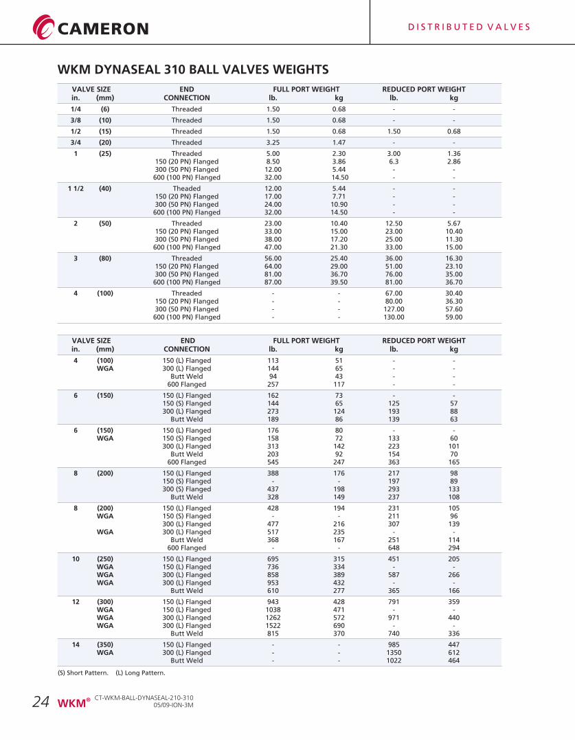
WKM DYNASEAL 310 BALL VALVES WEIGHTS
VALVE SIZE END FULL PORT WEIGHT REDUCED PORT WEIGHTin. (mm) CONNECTION lb. kg lb. kg
1/4 (6) Threaded 1.50 0.68 - -
3/8 (10) Threaded 1.50 0.68 - -
1/2 (15) Threaded 1.50 0.68 1.50 0.68
3/4 (20) Threaded 3.25 1.47 - -
1 (25) Threaded 5.00 2.30 3.00 1.36150 (20 PN) Flanged 8.50 3.86 6.3 2.86300 (50 PN) Flanged 12.00 5.44 - -
600 (100 PN) Flanged 32.00 14.50 - -
1 1/2 (40) Theaded 12.00 5.44 - -150 (20 PN) Flanged 17.00 7.71 - -300 (50 PN) Flanged 24.00 10.90 - -
600 (100 PN) Flanged 32.00 14.50 - -
2 (50) Threaded 23.00 10.40 12.50 5.67150 (20 PN) Flanged 33.00 15.00 23.00 10.40300 (50 PN) Flanged 38.00 17.20 25.00 11.30
600 (100 PN) Flanged 47.00 21.30 33.00 15.00
3 (80) Threaded 56.00 25.40 36.00 16.30150 (20 PN) Flanged 64.00 29.00 51.00 23.10300 (50 PN) Flanged 81.00 36.70 76.00 35.00
600 (100 PN) Flanged 87.00 39.50 81.00 36.70
4 (100) Threaded - - 67.00 30.40150 (20 PN) Flanged - - 80.00 36.30300 (50 PN) Flanged - - 127.00 57.60
600 (100 PN) Flanged - - 130.00 59.00
VALVE SIZE END FULL PORT WEIGHT REDUCED PORT WEIGHTin. (mm) CONNECTION lb. kg lb. kg
4 (100) 150 (L) Flanged 113 51 - -WGA 300 (L) Flanged 144 65 - -
Butt Weld 94 43 - -600 Flanged 257 117 - -
6 (150) 150 (L) Flanged 162 73 - -150 (S) Flanged 144 65 125 57300 (L) Flanged 273 124 193 88
Butt Weld 189 86 139 63
6 (150) 150 (L) Flanged 176 80 - -WGA 150 (S) Flanged 158 72 133 60
300 (L) Flanged 313 142 223 101Butt Weld 203 92 154 70
600 Flanged 545 247 363 165
8 (200) 150 (L) Flanged 388 176 217 98150 (S) Flanged - - 197 89300 (S) Flanged 437 198 293 133
Butt Weld 328 149 237 108
8 (200) 150 (L) Flanged 428 194 231 105WGA 150 (S) Flanged - - 211 96
300 (L) Flanged 477 216 307 139WGA 300 (L) Flanged 517 235 - -
Butt Weld 368 167 251 114600 Flanged - - 648 294
10 (250) 150 (L) Flanged 695 315 451 205WGA 150 (L) Flanged 736 334 - -WGA 300 (L) Flanged 858 389 587 266WGA 300 (L) Flanged 953 432 - -
Butt Weld 610 277 365 166
12 (300) 150 (L) Flanged 943 428 791 359WGA 150 (L) Flanged 1038 471 - -WGA 300 (L) Flanged 1262 572 971 440WGA 300 (L) Flanged 1522 690 - -
Butt Weld 815 370 740 336
14 (350) 150 (L) Flanged - - 985 447WGA 300 (L) Flanged - - 1350 612
Butt Weld - - 1022 464
(S) Short Pattern. (L) Long Pattern.
CT-WKM-BALL-DYNASEAL-210-31005/09-ION-3M
®WKM
D I S T R I B U T E D V A L V E S
25
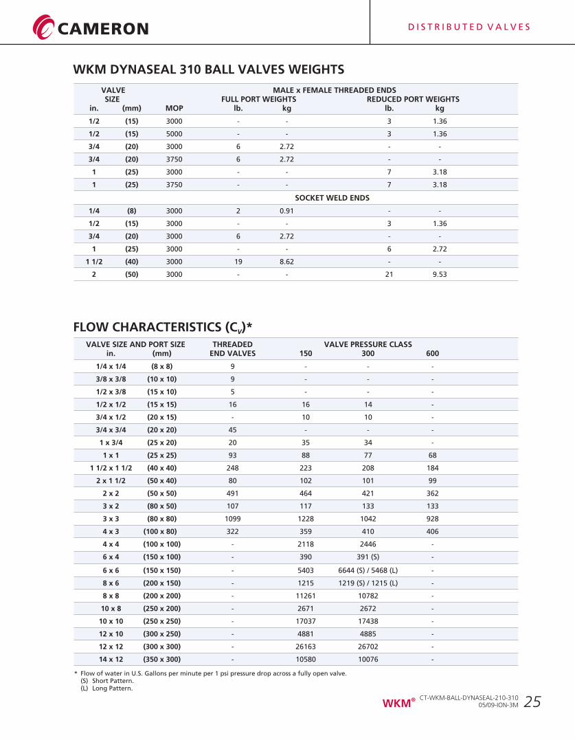
* Flow of water in U.S. Gallons per minute per 1 psi pressure drop across a fully open valve.(S) Short Pattern.(L) Long Pattern.
FLOW CHARACTERISTICS (C )*V
WKM DYNASEAL 310 BALL VALVES WEIGHTS
VALVE MALE x FEMALE THREADED ENDSSIZE FULL PORT WEIGHTS REDUCED PORT WEIGHTS
in. (mm) MOP lb. kg lb. kg
1/2 (15) 3000 - - 3 1.36
1/2 (15) 5000 - - 3 1.36
3/4 (20) 3000 6 2.72 - -
3/4 (20) 3750 6 2.72 - -
1 (25) 3000 - - 7 3.18
1 (25) 3750 - - 7 3.18
SOCKET WELD ENDS
1/4 (8) 3000 2 0.91 - -
1/2 (15) 3000 - - 3 1.36
3/4 (20) 3000 6 2.72 - -
1 (25) 3000 - - 6 2.72
1 1/2 (40) 3000 19 8.62 - -
2 (50) 3000 - - 21 9.53
VALVE SIZE AND PORT SIZE THREADED VALVE PRESSURE CLASSin. (mm) END VALVES 150 300 600
1/4 x 1/4 (8 x 8) 9 - - -
3/8 x 3/8 (10 x 10) 9 - - -
1/2 x 3/8 (15 x 10) 5 - - -
1/2 x 1/2 (15 x 15) 16 16 14 -
3/4 x 1/2 (20 x 15) - 10 10 -
3/4 x 3/4 (20 x 20) 45 - - -
1 x 3/4 (25 x 20) 20 35 34 -
1 x 1 (25 x 25) 93 88 77 68
1 1/2 x 1 1/2 (40 x 40) 248 223 208 184
2 x 1 1/2 (50 x 40) 80 102 101 99
2 x 2 (50 x 50) 491 464 421 362
3 x 2 (80 x 50) 107 117 133 133
3 x 3 (80 x 80) 1099 1228 1042 928
4 x 3 (100 x 80) 322 359 410 406
4 x 4 (100 x 100) - 2118 2446 -
6 x 4 (150 x 100) - 390 391 (S) -
6 x 6 (150 x 150) - 5403 6644 (S) / 5468 (L) -
8 x 6 (200 x 150) - 1215 1219 (S) / 1215 (L) -
8 x 8 (200 x 200) - 11261 10782 -
10 x 8 (250 x 200) - 2671 2672 -
10 x 10 (250 x 250) - 17037 17438 -
12 x 10 (300 x 250) - 4881 4885 -
12 x 12 (300 x 300) - 26163 26702 -
14 x 12 (350 x 300) - 10580 10076 -
CT-WKM-BALL-DYNASEAL-210-31005/09-ION-3M
®WKM
D I S T R I B U T E D V A L V E S
26
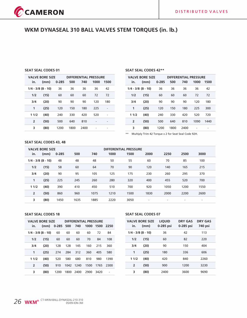
WKM DYNASEAL 310 BALL VALVES STEM TORQUES (in. lb.)
SEAT SEAL CODES 01
VALVE BORE SIZE DIFFERENTIAL PRESSURE
in. (mm) 0-285 500 740 1000 1500
1/4 - 3/8 (8 - 10) 36 36 36 36 42
1/2 (15) 60 60 60 72 72
3/4 (20) 90 90 90 120 180
1 (25) 120 150 180 225 -
1 1/2 (40) 240 330 420 520 -
2 (50) 500 640 810 - -
3 (80) 1200 1800 2400 - -
SEAT SEAL CODES 43, 48
VALVE BORE SIZE DIFFERENTIAL PRESSURE
in. (mm) 0-285 500 740 1000 1500 2000 2250 2500 3000
1/4 - 3/8 (8 - 10) 48 48 48 50 55 60 70 85 100
1/2 (15) 58 60 64 70 90 120 140 165 215
3/4 (20) 90 95 105 125 175 230 260 295 370
1 (25) 225 245 260 280 320 400 455 520 700
1 1/2 (40) 390 410 450 510 700 920 1050 1200 1550
2 (50) 860 960 1075 1210 1500 1830 2000 2200 2600
3 (80) 1450 1635 1885 2220 3050 - - - -
SEAT SEAL CODES 18
VALVE BORE SIZE DIFFERENTIAL PRESSURE
in. (mm) 0-285 500 740 1000 1500 2250
1/4 - 3/8 (8 - 10) 60 60 60 60 72 84
1/2 (15) 60 60 60 70 84 108
3/4 (20) 128 128 145 160 215 360
1 (25) 274 284 312 360 405 580
1 1/2 (40) 520 580 680 810 980 1390
2 (50) 910 1042 1240 1500 1765 2300
3 (80) 1200 1800 2400 2900 3420 -
SEAT SEAL CODES 42**
VALVE BORE SIZE DIFFERENTIAL PRESSURE
in. (mm) 0-285 500 740 1000 1500
1/4 - 3/8 (8 - 10) 36 36 36 36 42
1/2 (15) 60 60 60 72 72
3/4 (20) 90 90 90 120 180
1 (25) 120 150 180 225 300
1 1/2 (40) 240 330 420 520 720
2 (50) 500 640 810 1090 1440
3 (80) 1200 1800 2400 - -
SEAT SEAL CODES 07
VALVE BORE SIZE LIQUID DRY GAS DRY GAS
in. (mm) 0-285 psi 0-285 psi 740 psi
1/4 - 3/8 (8 - 10) 36 42 113
1/2 (15) 60 82 220
3/4 (20) 90 150 404
1 (25) 180 336 606
1 1/2 (40) 420 840 2260
2 (50) 900 1200 3230
3 (80) 2400 3600 9690
** Multiply Trim 42 Torque x 2 for Seat Seal Code 92H.
CT-WKM-BALL-DYNASEAL-210-31005/09-ION-3M
®WKM
D I S T R I B U T E D V A L V E S
27
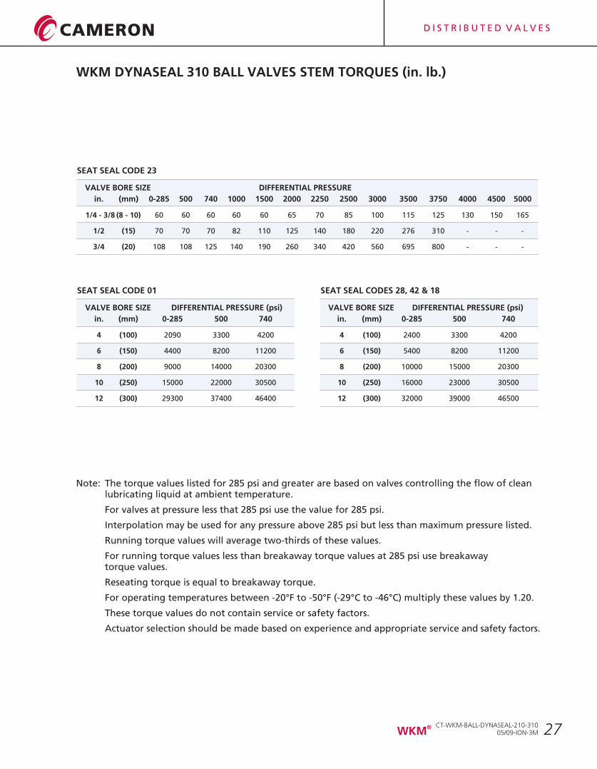
WKM DYNASEAL 310 BALL VALVES STEM TORQUES (in. lb.)
SEAT SEAL CODE 23
VALVE BORE SIZE DIFFERENTIAL PRESSURE
in. (mm) 0-285 500 740 1000 1500 2000 2250 2500 3000 3500 3750 4000 4500 5000
1/4 - 3/8 (8 - 10) 60 60 60 60 60 65 70 85 100 115 125 130 150 165
1/2 (15) 70 70 70 82 110 125 140 180 220 276 310 - - -
3/4 (20) 108 108 125 140 190 260 340 420 560 695 800 - - -
Note: The torque values listed for 285 psi and greater are based on valves controlling the flow of clean lubricating liquid at ambient temperature.
For valves at pressure less that 285 psi use the value for 285 psi.
Interpolation may be used for any pressure above 285 psi but less than maximum pressure listed.
Running torque values will average two-thirds of these values.
For running torque values less than breakaway torque values at 285 psi use breakawaytorque values.
Reseating torque is equal to breakaway torque.
For operating temperatures between -20°F to -50°F (-29°C to -46°C) multiply these values by 1.20.
These torque values do not contain service or safety factors.
Actuator selection should be made based on experience and appropriate service and safety factors.
SEAT SEAL CODE 01
VALVE BORE SIZE
in. (mm) 0-285 500 740
4 (100) 2090 3300 4200
6 (150) 4400 8200 11200
8 (200) 9000 14000 20300
10 (250) 15000 22000 30500
12 (300) 29300 37400 46400
DIFFERENTIAL PRESSURE (psi)
SEAT SEAL CODES 28, 42 & 18
VALVE BORE SIZE
in. (mm) 0-285 500 740
4 (100) 2400 3300 4200
6 (150) 5400 8200 11200
8 (200) 10000 15000 20300
10 (250) 16000 23000 30500
12 (300) 32000 39000 46500
DIFFERENTIAL PRESSURE (psi)
CT-WKM-BALL-DYNASEAL-210-31005/09-ION-3M
®WKM
D I S T R I B U T E D V A L V E S
28
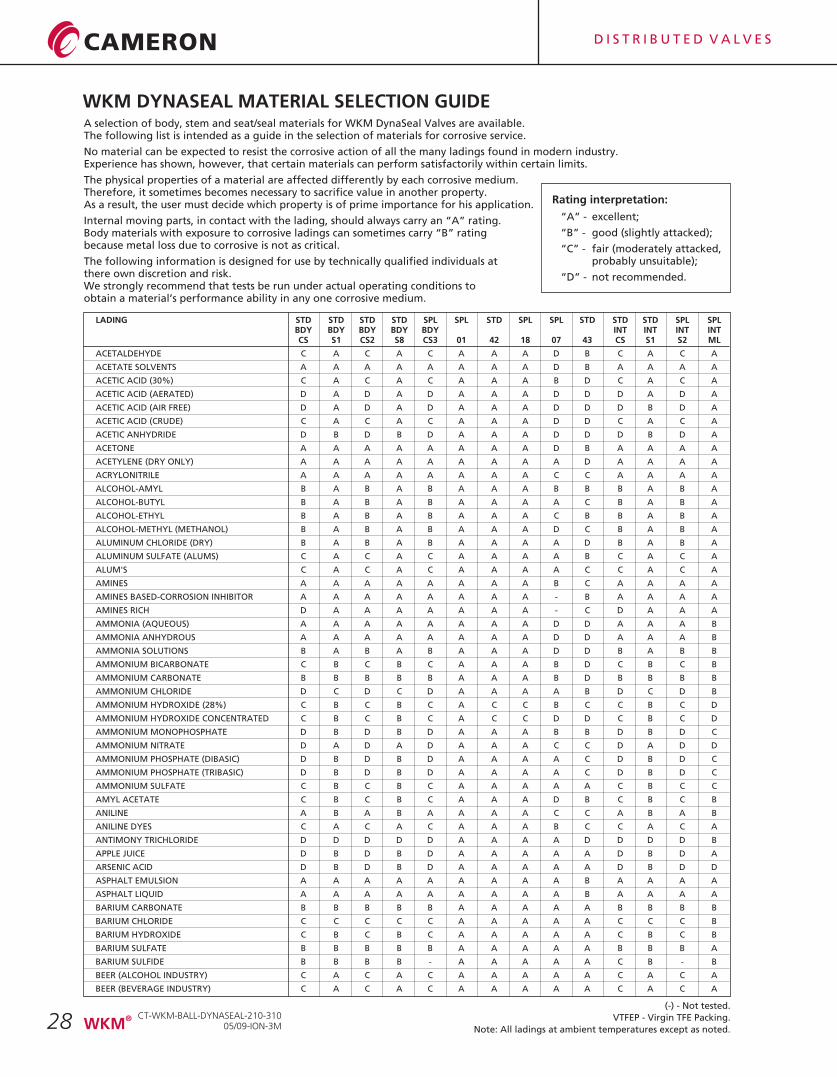
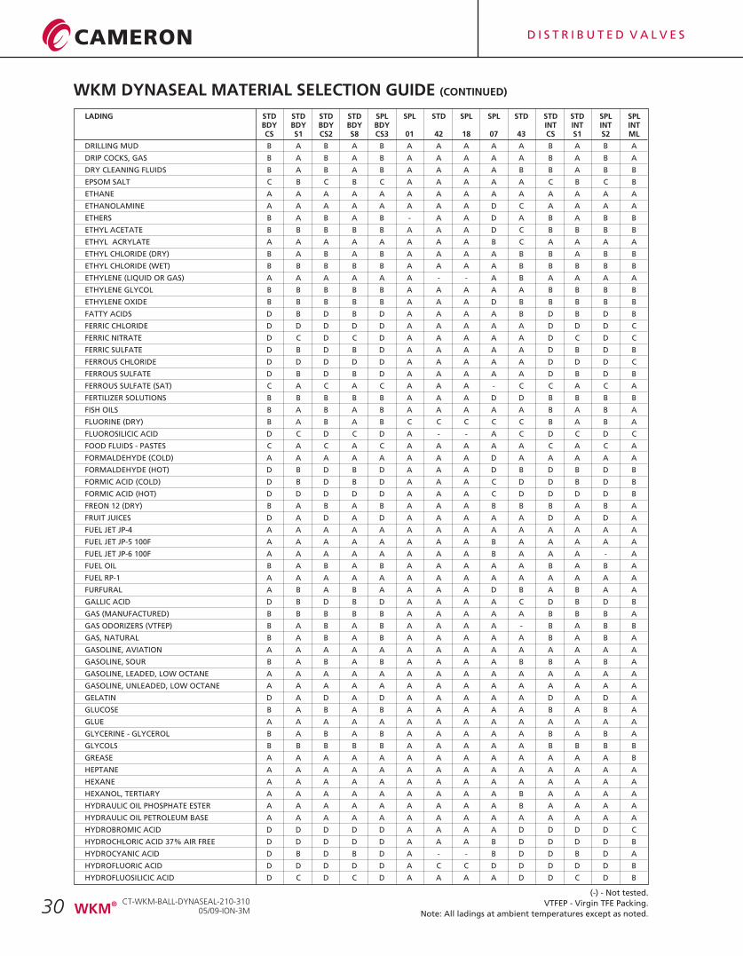
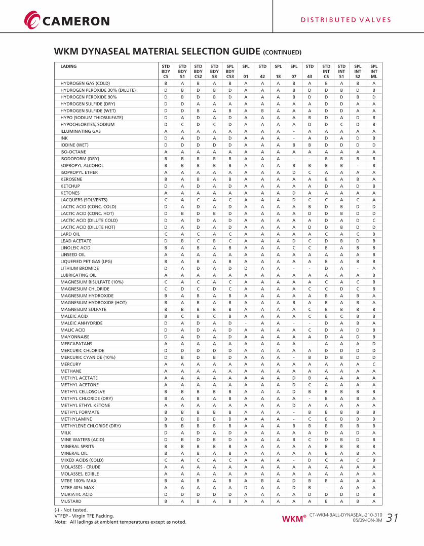
WKM DYNASEAL MATERIAL SELECTION GUIDEA selection of body, stem and seat/seal materials for WKM DynaSeal Valves are available.The following list is intended as a guide in the selection of materials for corrosive service.
No material can be expected to resist the corrosive action of all the many ladings found in modern industry.Experience has shown, however, that certain materials can perform satisfactorily within certain limits.
The physical properties of a material are affected differently by each corrosive medium.Therefore, it sometimes becomes necessary to sacrifice value in another property.As a result, the user must decide which property is of prime importance for his application.
Internal moving parts, in contact with the lading, should always carry an “A” rating.Body materials with exposure to corrosive ladings can sometimes carry “B” rating because metal loss due to corrosive is not as critical.
The following information is designed for use by technically qualified individuals at there own discretion and risk.We strongly recommend that tests be run under actual operating conditions to obtain a material’s performance ability in any one corrosive medium.
(-) - Not tested.
VTFEP - Virgin TFE Packing.
Note: All ladings at ambient temperatures except as noted.
LADING STD STD STD STD SPL SPL STD SPL SPL STD STD STD SPL SPLBDY BDY BDY BDY BDY INT INT INT INTCS S1 CS2 S8 CS3 01 42 18 07 43 CS S1 S2 ML
ACETALDEHYDE C A C A C A A A D B C A C A
ACETATE SOLVENTS A A A A A A A A D B A A A A
ACETIC ACID (30%) C A C A C A A A B D C A C A
ACETIC ACID (AERATED) D A D A D A A A D D D A D A
ACETIC ACID (AIR FREE) D A D A D A A A D D D B D A
ACETIC ACID (CRUDE) C A C A C A A A D D C A C A
ACETIC ANHYDRIDE D B D B D A A A D D D B D A
ACETONE A A A A A A A A D B A A A A
ACETYLENE (DRY ONLY) A A A A A A A A A D A A A A
ACRYLONITRILE A A A A A A A A C C A A A A
ALCOHOL-AMYL B A B A B A A A B B B A B A
ALCOHOL-BUTYL B A B A B A A A A C B A B A
ALCOHOL-ETHYL B A B A B A A A C B B A B A
ALCOHOL-METHYL (METHANOL) B A B A B A A A D C B A B A
ALUMINUM CHLORIDE (DRY) B A B A B A A A A D B A B A
ALUMINUM SULFATE (ALUMS) C A C A C A A A A B C A C A
ALUM'S C A C A C A A A A C C A C A
AMINES A A A A A A A A B C A A A A
AMINES BASED-CORROSION INHIBITOR A A A A A A A A - B A A A A
AMINES RICH D A A A A A A A - C D A A A
AMMONIA (AQUEOUS) A A A A A A A A D D A A A B
AMMONIA ANHYDROUS A A A A A A A A D D A A A B
AMMONIA SOLUTIONS B A B A B A A A D D B A B B
AMMONIUM BICARBONATE C B C B C A A A B D C B C B
AMMONIUM CARBONATE B B B B B A A A B D B B B B
AMMONIUM CHLORIDE D C D C D A A A A B D C D B
AMMONIUM HYDROXIDE (28%) C B C B C A C C B C C B C D
AMMONIUM HYDROXIDE CONCENTRATED C B C B C A C C D D C B C D
AMMONIUM MONOPHOSPHATE D B D B D A A A B B D B D C
AMMONIUM NITRATE D A D A D A A A C C D A D D
AMMONIUM PHOSPHATE (DIBASIC) D B D B D A A A A C D B D C
AMMONIUM PHOSPHATE (TRIBASIC) D B D B D A A A A C D B D C
AMMONIUM SULFATE C B C B C A A A A A C B C C
AMYL ACETATE C B C B C A A A D B C B C B
ANILINE A B A B A A A A C C A B A B
ANILINE DYES C A C A C A A A B C C A C A
ANTIMONY TRICHLORIDE D D D D D A A A A D D D D B
APPLE JUICE D B D B D A A A A A D B D A
ARSENIC ACID D B D B D A A A A A D B D D
ASPHALT EMULSION A A A A A A A A A B A A A A
ASPHALT LIQUID A A A A A A A A A B A A A A
BARIUM CARBONATE B B B B B A A A A A B B B B
BARIUM CHLORIDE C C C C C A A A A A C C C B
BARIUM HYDROXIDE C B C B C A A A A A C B C B
BARIUM SULFATE B B B B B A A A A A B B B A
BARIUM SULFIDE B B B B - A A A A A C B - B
BEER (ALCOHOL INDUSTRY) C A C A C A A A A A C A C A
BEER (BEVERAGE INDUSTRY) C A C A C A A A A A C A C A
Rating interpretation:
“A” - excellent;
“B” - good (slightly attacked);
“C” - fair (moderately attacked, probably unsuitable);
“D” - not recommended.
CT-WKM-BALL-DYNASEAL-210-31005/09-ION-3M
®WKM
D I S T R I B U T E D V A L V E S
29
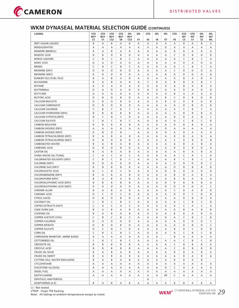
LADING STD STD STD STD SPL SPL STD SPL SPL STD STD STD SPL SPLBDY BDY BDY BDY BDY INT INT INT INTCS S1 CS2 S8 CS3 01 42 18 07 43 CS S1 S2 ML
BEET SUGAR LIQUIDS B A B A B A A A A A B A B A
BENZALDEHYDE A A A A A A A A D A A A A A
BENZENE (BENZOL) B A B A B A A A A B B A B A
BENZOIC ACID D B D B D A A A A C D B D B
BORAX LIQUORS C B C B C A A A A A C B C A
BORIC ACID D A D A D A A A A A D A D A
BRINES C B C B C A A A A A C B C A
BROMINE (DRY) D D D D D A A A A C D D D A
BROMINE (WET) D D D D D A A A B D D D D B
BUNKER OILS (FUEL OILS) B A B A B A A A A A B A B A
BUTADIENE B A B A B A C D A B B A B C
BUTANE A A A A A A A A A A B A B A
BUTTERMILK D A D A D A A A A A D A D D
BUTYLENE A A A A A A A A A B A A A A
BUTYRIC ACID D B D B D A A A B C D B D B
CALCIUM BISULFITE D B D B D A A A B D D B D B
CALCIUM CARBONATE D B D B D A A A A A D B D B
CALCIUM CHLORIDE C B C B C A A A A A C B C A
CALCIUM HYDROXIDE (20%) B B B B B A A A A A B B B A
CALCIUM HYPOCHLORITE D C D C D A A A A D D A D C
CALCIUM SULFATE C B C B C A A A A A C B C B
CARBON BISULFIDE B B B B B A A A A D B B B A
CARBON DIOXIDE (DRY) A A A A A A A A D A A A A A
CARBON DIOXIDE (WET) D B D B - A A A D A D A A A
CARBON TETRACHLORIDE (DRY) B A B A B A A A A B B A B A
CARBON TETRACHLORIDE (WET) D B D B D A A A A C D B D B
CARBONATED WATER B A B A B A A A A A B A B A
CARBONIC ACID D B D B D A A A A B D B D A
CASTOR OIL B A B A B A A A A A B A B A
CHINA WOOD OIL (TUNG) C A C A C A A A A A C A C A
CHLORINATED SOLVENTS (DRY) C B C B C A A A A B C B C B
CHLORINE (WET) D D D D D A A A A D D D D C
CHLORINE GAS (DRY) B B B B B A A A A D B B B B
CHLOROACETIC ACID D C D C D A A A D D D D D B
CHLOROBENZENE (DRY) B A B A B A A A A B B A B A
CHLOROFORM (DRY) B A B A B A A A A B B A B A
CHLOROSULPHONIC ACID (DRY) B B B B B A A A D D B B B A
CHLOROSULPHONIC ACID (WET) D D D D D A A A D D D D D C
CHROME ALUM B A B A B A A A A C B A B B
CHROMIC ACID D C D C D A A A A D D C D B
CITRUS JUICES D B D B D A A A A A D B D A
COCONUT OIL C B C B C A A A A A C B C B
COFFEE EXTRACTS (HOT) C A C A C A A A A A C A C A
COKE OVEN GAS B A B A B A A A A D B A B B
COOKING OIL B A B A B A A A A B B A B A
COPPER ACETATE (10%) C B C B C A A A D A C B C B
COPPER CHLORIDE D D D D D A A A A A D D D C
COPPER NITRATE D B D B D A A A A A D B D C
COPPER SULFATE D C D C D A A A A B D C D B
CORN OIL C B C B C A A A A A C B C B
CORROSION INHIBITOR- AMINE BASED A A A A A A A A - B A A A A
COTTONSEED OIL C B C B C A A A A A C B C B
CREOSOTE OIL B B B B B A A A A C B B B A
CRESYLIC ACID B B B B B A A A A C B B B B
CRUDE OIL SOUR B A B A B A A A A B B A B A
CRUDE OIL SWEET B A B A B A A A A A B A B A
CUTTING OILS, WATER EMULSIONS B A B A B A A A A B B A B -
CYCLOHEXANE A A A A A A A A A A A A A A
DIACETONE ALCOHOL A A A A A A A A D C A A A A
DIESEL FUEL A A A A A A A A A A A A A A
DIETHYLAMINE A A A A A A A A HF C A A A A
DIPHTALIC ANHYDROUS - - - - - - A - - - - - - -
DOWTHERMS (A-E) B A B A B A A A A B B A B A
(-) - Not tested.
VTFEP - Virgin TFE Packing.
Note: All ladings at ambient temperatures except as noted.
WKM DYNASEAL MATERIAL SELECTION GUIDE (CONTINUED)
CT-WKM-BALL-DYNASEAL-210-31005/09-ION-3M
®WKM
D I S T R I B U T E D V A L V E S
30
WKM DYNASEAL MATERIAL SELECTION GUIDE (CONTINUED)
LADING STD STD STD STD SPL SPL STD SPL SPL STD STD STD SPL SPLBDY BDY BDY BDY BDY INT INT INT INTCS S1 CS2 S8 CS3 01 42 18 07 43 CS S1 S2 ML
DRILLING MUD B A B A B A A A A A B A B A
DRIP COCKS, GAS B A B A B A A A A A B A B A
DRY CLEANING FLUIDS B A B A B A A A A B B A B B
EPSOM SALT C B C B C A A A A A C B C B
ETHANE A A A A A A A A A A A A A A
ETHANOLAMINE A A A A A A A A D C A A A A
ETHERS B A B A B - A A D A B A B B
ETHYL ACETATE B B B B B A A A D C B B B B
ETHYL ACRYLATE A A A A A A A A B C A A A A
ETHYL CHLORIDE (DRY) B A B A B A A A A B B A B B
ETHYL CHLORIDE (WET) B B B B B A A A A B B B B B
ETHYLENE (LIQUID OR GAS) A A A A A A - - A B A A A A
ETHYLENE GLYCOL B B B B B A A A A A B B B B
ETHYLENE OXIDE B B B B B A A A D B B B B B
FATTY ACIDS D B D B D A A A A B D B D B
FERRIC CHLORIDE D D D D D A A A A A D D D C
FERRIC NITRATE D C D C D A A A A A D C D C
FERRIC SULFATE D B D B D A A A A A D B D B
FERROUS CHLORIDE D D D D D A A A A A D D D C
FERROUS SULFATE D B D B D A A A A A D B D B
FERROUS SULFATE (SAT) C A C A C A A A - C C A C A
FERTILIZER SOLUTIONS B B B B B A A A D D B B B B
FISH OILS B A B A B A A A A A B A B A
FLUORINE (DRY) B A B A B C C C C C B A B A
FLUOROSILICIC ACID D C D C D A - - A C D C D C
FOOD FLUIDS - PASTES C A C A C A A A A A C A C A
FORMALDEHYDE (COLD) A A A A A A A A D A A A A A
FORMALDEHYDE (HOT) D B D B D A A A D B D B D B
FORMIC ACID (COLD) D B D B D A A A C D D B D B
FORMIC ACID (HOT) D D D D D A A A C D D D D B
FREON 12 (DRY) B A B A B A A A B B B A B A
FRUIT JUICES D A D A D A A A A A D A D A
FUEL JET JP-4 A A A A A A A A A A A A A A
FUEL JET JP-5 100F A A A A A A A A B A A A A A
FUEL JET JP-6 100F A A A A A A A A B A A A - A
FUEL OIL B A B A B A A A A A B A B A
FUEL RP-1 A A A A A A A A A A A A A A
FURFURAL A B A B A A A A D B A B A A
GALLIC ACID D B D B D A A A A C D B D B
GAS (MANUFACTURED) B B B B B A A A A A B B B A
GAS ODORIZERS (VTFEP) B A B A B A A A A - B A B B
GAS, NATURAL B A B A B A A A A A B A B A
GASOLINE, AVIATION A A A A A A A A A A A A A A
GASOLINE, SOUR B A B A B A A A A B B A B A
GASOLINE, LEADED, LOW OCTANE A A A A A A A A A A A A A A
GASOLINE, UNLEADED, LOW OCTANE A A A A A A A A A A A A A A
GELATIN D A D A D A A A A A D A D A
GLUCOSE B A B A B A A A A A B A B A
GLUE A A A A A A A A A A A A A A
GLYCERINE - GLYCEROL B A B A B A A A A A B A B A
GLYCOLS B B B B B A A A A A B B B B
GREASE A A A A A A A A A A A A A B
HEPTANE A A A A A A A A A A A A A A
HEXANE A A A A A A A A A A A A A A
HEXANOL, TERTIARY A A A A A A A A A B A A A A
HYDRAULIC OIL PHOSPHATE ESTER A A A A A A A A A B A A A A
HYDRAULIC OIL PETROLEUM BASE A A A A A A A A A A A A A A
HYDROBROMIC ACID D D D D D A A A A D D D D C
HYDROCHLORIC ACID 37% AIR FREE D D D D D A A A B D D D D B
HYDROCYANIC ACID D B D B D A - - B D D B D A
HYDROFLUORIC ACID D D D D D A C C D D D D D B
HYDROFLUOSILICIC ACID D C D C D A A A A D D C D B
(-) - Not tested.
VTFEP - Virgin TFE Packing.
Note: All ladings at ambient temperatures except as noted.
CT-WKM-BALL-DYNASEAL-210-31005/09-ION-3M
®WKM
D I S T R I B U T E D V A L V E S
31
LADING STD STD STD STD SPL SPL STD SPL SPL STD STD STD SPL SPLBDY BDY BDY BDY BDY INT INT INT INTCS S1 CS2 S8 CS3 01 42 18 07 43 CS S1 S2 ML
HYDROGEN GAS (COLD) B A B A B A A A B A B A B A
HYDROGEN PEROXIDE 30% (DILUTE) D B D B D A A A B D D B D B
HYDROGEN PEROXIDE 90% D B D B D A A A B D D D B D
HYDROGEN SULFIDE (DRY) D D A A A A A A A A D D A A
HYDROGEN SULFIDE (WET) D D B A B A B A A A D D A A
HYPO (SODIUM THIOSULFATE) D A D A D A A A A B D A D B
HYPOCHLORITES, SODIUM D C D C D A A A A D D C D B
ILLUMINATING GAS A A A A A A A A - A A A A A
INK D A D A D A A A - A D A D B
IODINE (WET) D D D D D A A A B B D D D D
ISO-OCTANE A A A A A A A A A A A A A A
ISODOFORM (DRY) B B B B B A A A - - B B B B
SOPROPYL ALCOHOL B B B B B A A A B B B B - B
ISOPROPYL ETHER A A A A A A A A D C A A A A
KEROSENE B A B A B A A A A A B A B A
KETCHUP D A D A D A A A A A D A D B
KETONES A A A A A A A A D A A A A A
LACQUERS (SOLVENTS) C A C A C A A A D C C A C A
LACTIC ACID (CONC. COLD) D A D A D A A A A B D B D D
LACTIC ACID (CONC. HOT) D B D B D A A A A D D B D D
LACTIC ACID (DILUTE COLD) D A D A D A A A A A D A D C
LACTIC ACID (DILUTE HOT) D A D A D A A A A D D B D D
LARD OIL C A C A C A A A A A C A C B
LEAD ACETATE D B C B C A A A D C D B D B
LINOLEIC ACID B A B A B A A A C C B A B B
LINSEED OIL A A A A A A A A A A A A A B
LIQUEFIED PET GAS (LPG) B A B A B A A A A A B A B B
LITHIUM BROMIDE D A D A D D A A - - D A - A
LUBRICATING OIL A A A A A A A A A A A A A B
MAGNESIUM BISULFATE (10%) C A C A C A A A A A C A C B
MAGNESIUM CHLORIDE C D C D C A A A A C C D C B
MAGNESIUM HYDROXIDE B A B A B A A A A A B A B A
MAGNESIUM HYDROXIDE (HOT) B A B A B A A A B A B A B A
MAGNESIUM SULFATE B B B B B A A A A C B B B B
MALEIC ACID B C B C B A A A A C B C B B
MALEIC ANHYDRIDE D A D A D - A A - - D A B A
MALIC ACID D A D A D A A A A C D A D B
MAYONNAISE D A D A D A A A A A D A D B
MERCAPATANS A A A A A A A A A - A A A D
MERCURIC CHLORIDE D D D D D A A A A A D D D D
MERCURIC CYANIDE (10%) D B D B D A A A - B D B D D
MERCURY A A A A A A A A A A A A A C
METHANE A A A A A A A A A A A A A A
METHYL ACETATE A A A A A A A A D B A A A A
METHYL ACETONE A A A A A A A A D C A A A A
METHYL CELLOSOLVE B B B B B A A A D B B B B B
METHYL CHLORIDE (DRY) B A B A B A A A A - B A B A
METHYL ETHYL KETONE A A A A A A A A D A A A A A
METHYL FORMATE B B B B B A A A - B B B B B
METHYLAMINE B B B B B A A A - C B B B B
METHYLENE CHLORIDE (DRY) B B B B B A A A B B B B B B
MILK D A D A D A A A A A D A D A
MINE WATERS (ACID) D B D B D A A A B C D B D B
MINERAL SPRITS B B B B B A A A A A B B B B
MINERAL OIL B A B A B A A A A A B A B A
MIXED ACIDS (COLD) C A C A C A A A - D C A C B
MOLASSES - CRUDE A A A A A A A A A A A A A A
MOLASSES, EDIBLE A A A A A A A A A A A A A A
MTBE 100% MAX B A B A B A B A D B B A A A
MTBE 40% MAX A A A A A D A A D B - A A A
MURIATIC ACID D D D D D A A A A D D D D B
MUSTARD B A B A B A A A A A B A B A
WKM DYNASEAL MATERIAL SELECTION GUIDE (CONTINUED)
(-) - Not tested.
VTFEP - Virgin TFE Packing.
Note: All ladings at ambient temperatures except as noted.
CT-WKM-BALL-DYNASEAL-210-31005/09-ION-3M
®WKM
D I S T R I B U T E D V A L V E S
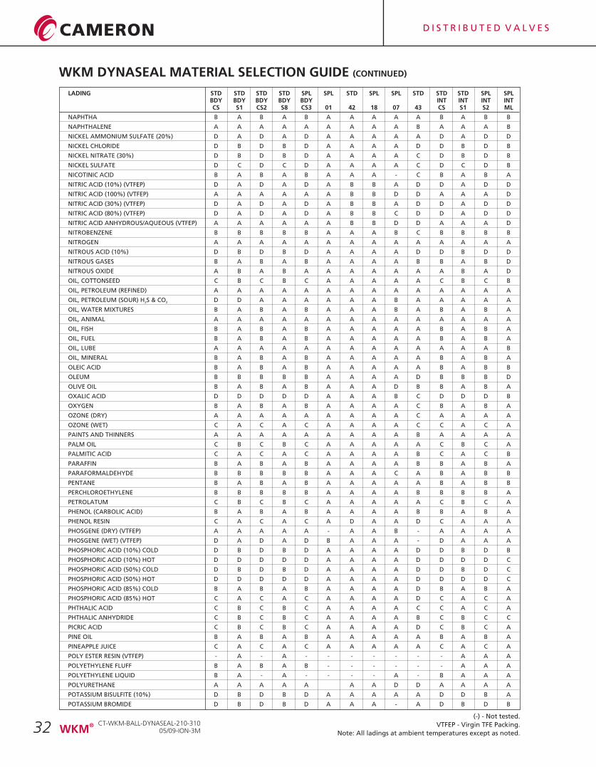
32
LADING STD STD STD STD SPL SPL STD SPL SPL STD STD STD SPL SPLBDY BDY BDY BDY BDY INT INT INT INTCS S1 CS2 S8 CS3 01 42 18 07 43 CS S1 S2 ML
NAPHTHA B A B A B A A A A A B A B B
NAPHTHALENE A A A A A A A A A B A A A B
NICKEL AMMONIUM SULFATE (20%) D A D A D A A A A A D A D D
NICKEL CHLORIDE D B D B D A A A A D D B D B
NICKEL NITRATE (30%) D B D B D A A A A C D B D B
NICKEL SULFATE D C D C D A A A A C D C D B
NICOTINIC ACID B A B A B A A A - C B A B A
NITRIC ACID (10%) (VTFEP) D A D A D A B B A D D A D D
NITRIC ACID (100%) (VTFEP) A A A A A A B B D D A A A D
NITRIC ACID (30%) (VTFEP) D A D A D A B B A D D A D D
NITRIC ACID (80%) (VTFEP) D A D A D A B B C D D A D D
NITRIC ACID ANHYDROUS/AQUEOUS (VTFEP) A A A A A A B B D D A A A D
NITROBENZENE B B B B B A A A B C B B B B
NITROGEN A A A A A A A A A A A A A A
NITROUS ACID (10%) D B D B D A A A A D D B D D
NITROUS GASES B A B A B A A A A B B A B D
NITROUS OXIDE A B A B A A A A A A A B A D
OIL, COTTONSEED C B C B C A A A A A C B C B
OIL, PETROLEUM (REFINED) A A A A A A A A A A A A A A
OIL, PETROLEUM (SOUR) H S & CO D D A A A A A A B A A A A A2 2
OIL, WATER MIXTURES B A B A B A A A B A B A B A
OIL, ANIMAL A A A A A A A A A A A A A A
OIL, FISH B A B A B A A A A A B A B A
OIL, FUEL B A B A B A A A A A B A B A
OIL, LUBE A A A A A A A A A A A A A B
OIL, MINERAL B A B A B A A A A A B A B A
OLEIC ACID B A B A B A A A A A B A B B
OLEUM B B B B B A A A A D B B B D
OLIVE OIL B A B A B A A A D B B A B A
OXALIC ACID D D D D D A A A B C D D D B
OXYGEN B A B A B A A A A C B A B A
OZONE (DRY) A A A A A A A A A C A A A A
OZONE (WET) C A C A C A A A A C C A C A
PAINTS AND THINNERS A A A A A A A A A B A A A A
PALM OIL C B C B C A A A A A C B C A
PALMITIC ACID C A C A C A A A A B C A C B
PARAFFIN B A B A B A A A A B B A B A
PARAFORMALDEHYDE B B B B B A A A C A B A B B
PENTANE B A B A B A A A A A B A B B
PERCHLOROETHYLENE B B B B B A A A A B B B B A
PETROLATUM C B C B C A A A A A C B C A
PHENOL (CARBOLIC ACID) B A B A B A A A A B B A B A
PHENOL RESIN C A C A C A D A A D C A A A
PHOSGENE (DRY) (VTFEP) A A A A A - A A B - A A A A
PHOSGENE (WET) (VTFEP) D A D A D B A A A - D A A A
PHOSPHORIC ACID (10%) COLD D B D B D A A A A D D B D B
PHOSPHORIC ACID (10%) HOT D D D D D A A A A D D D D C
PHOSPHORIC ACID (50%) COLD D B D B D A A A A D D B D C
PHOSPHORIC ACID (50%) HOT D D D D D A A A A D D D D C
PHOSPHORIC ACID (85%) COLD B A B A B A A A A D B A B A
PHOSPHORIC ACID (85%) HOT C A C A C A A A A D C A C A
PHTHALIC ACID C B C B C A A A A C C A C A
PHTHALIC ANHYDRIDE C B C B C A A A A B C B C C
PICRIC ACID C B C B C A A A A D C B C A
PINE OIL B A B A B A A A A A B A B A
PINEAPPLE JUICE C A C A C A A A A A C A C A
POLY ESTER RESIN (VTFEP) - A - A - - - - - - - A A A
POLYETHYLENE FLUFF B A B A B - - - - - - A A A
POLYETHYLENE LIQUID B A - A - - - - A - B A A A
POLYURETHANE A A A A A A A D D A A A A
POTASSIUM BISULFITE (10%) D B D B D A A A A A D D B A
POTASSIUM BROMIDE D B D B D A A A - A D B D B
WKM DYNASEAL MATERIAL SELECTION GUIDE (CONTINUED)
(-) - Not tested.
VTFEP - Virgin TFE Packing.
Note: All ladings at ambient temperatures except as noted.
CT-WKM-BALL-DYNASEAL-210-31005/09-ION-3M
®WKM
D I S T R I B U T E D V A L V E S
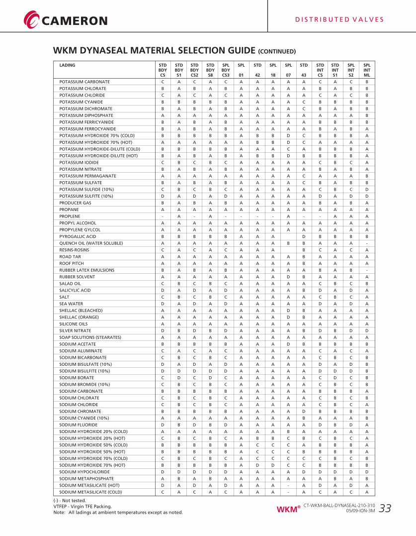
33
LADING STD STD STD STD SPL SPL STD SPL SPL STD STD STD SPL SPLBDY BDY BDY BDY BDY INT INT INT INTCS S1 CS2 S8 CS3 01 42 18 07 43 CS S1 S2 ML
POTASSIUM CARBONATE C A C A C A A A A A C A C B
POTASSIUM CHLORATE B A B A B A A A A A B A B B
POTASSIUM CHLORIDE C A C A C A A A A A C A C B
POTASSIUM CYANIDE B B B B B A A A A C B B B B
POTASSIUM DICHROMATE B A B A B A A A A C B A B B
POTASSIUM DIPHOSPHATE A A A A A A A A A A A A A B
POTASSIUM FERRICYANIDE B A B A B A A A A A B B B B
POTASSIUM FERROCYANIDE B A B A B A A A A A B A B A
POTASSIUM HYDROXIDE 70% (COLD) B B B B B A B B D C B B B A
POTASSIUM HYDROXIDE 70% (HOT) A A A A A A B B D C A A A A
POTASSIUM HYDROXIDE-DILUTE (COLD) B B B B B A A A C A B B B A
POTASSIUM HYDROXIDE-DILUTE (HOT) B A B A B A B B D B B B B A
POTASSIUM IODIDE C B C B C A A A A A C B C A
POTASSIUM NITRATE B A B A B A A A A A B A B A
POTASSIUM PERMAGANATE A A A A A A A A A C A A A B
POTASSIUM SULFATE B A B A B A A A A C B A B B
POTASSIUM SULFIDE (10%) C B C B C A A A A A C B C D
POTASSIUM SULFITE (10%) D A D A D A A A A A D A D D
PRODUCER GAS B A B A B A A A A A B A B A
PROPANE A A A A A A A A A A A A A A
PROPLENE - A - A - - - - A - - A A A
PROPYL ALCOHOL A A A A A A A A A A A A A A
PROPYLENE GYLCOL A A A A A A A A A A A A A A
PYROGALLIC ACID B B B B B A A A D B B B B
QUENCH OIL (WATER SOLUBLE) A A A A A A A A B B A A A -
RESINS-ROSINS C A C A C A A A B C A C A
ROAD TAR A A A A A A A A A B A A A A
ROOF PITCH A A A A A A A A A B A A A A
RUBBER LATEX EMULSIONS B A B A B A A A A A B A B -
RUBBER SOLVENT A A A A A A A A D B A A A A
SALAD OIL C B C B C A A A A A C B C B
SALICYLIC ACID D A D A D A A A A B D A D A
SALT C B C B C A A A A A C B C A
SEA WATER D A D A D A A A A A D A D A
SHELLAC (BLEACHED) A A A A A A A A D B A A A A
SHELLAC (ORANGE) A A A A A A A A D B A A A A
SILICONE OILS A A A A A A A A A A A A A A
SILVER NITRATE D B D B D A A A A B D B D D
SOAP SOLUTIONS (STEARATES) A A A A A A A A A A A A A A
SODIUM ACETATE B B B B B A A A D B B B B B
SODIUM ALUMINATE C A C A C A A A A A C A C A
SODIUM BICARBONATE C B C B C A A A A A C B C B
SODIUM BISULFATE (10%) D A D A D A A A A A D A D B
SODIUM BISULFITE (10%) D D D D D A A A A A D D D B
SODIUM BORATE C D C D C A A A A A C D C B
SODIUM BROMIDE (10%) C B C B C A A A A A C B C B
SODIUM CARBONATE B B B B B A A A A A B B B A
SODIUM CHLORATE C B C B C A A A A A C B C B
SODIUM CHLORIDE C B C B C A A A A A C B C A
SODIUM CHROMATE B B B B B A A A A D B B B B
SODIUM CYANIDE (10%) A A A A A A A A A B A A A B
SODIUM FLUORIDE D B D B D A A A A A D B D A
SODIUM HYDROXIDE 20% (COLD) A A A A A A A A B A A A A A
SODIUM HYDROXIDE 20% (HOT) C B C B C A B B C B C B C A
SODIUM HYDROXIDE 50% (COLD) B B B B B A C C C A B B B A
SODIUM HYDROXIDE 50% (HOT) B B B B B A C C C B B B B A
SODIUM HYDROXIDE 70% (COLD) C B C B C A C C C C C B C B
SODIUM HYDROXIDE 70% (HOT) B B B B B A D D C C B B B B
SODIUM HYPOCHLORIDE D D D D D A A A A D D D D D
SODIUM METAPHOSPHATE A B A B A A A A A A A B A B
SODIUM METASILICATE (HOT) D A D A D A A A - A D A D A
SODIUM METASILICATE (COLD) C A C A C A A A - A C A C A
WKM DYNASEAL MATERIAL SELECTION GUIDE (CONTINUED)
(-) - Not tested.
VTFEP - Virgin TFE Packing.
Note: All ladings at ambient temperatures except as noted.
CT-WKM-BALL-DYNASEAL-210-31005/09-ION-3M
®WKM
D I S T R I B U T E D V A L V E S
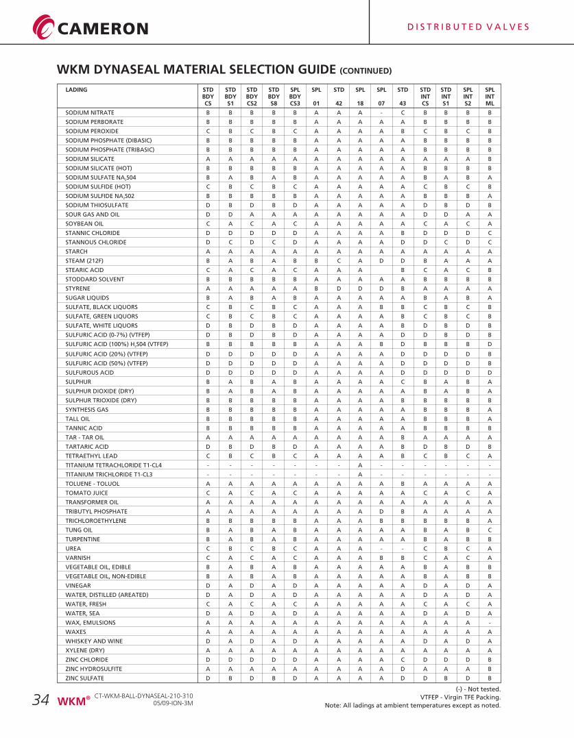
34
LADING STD STD STD STD SPL SPL STD SPL SPL STD STD STD SPL SPLBDY BDY BDY BDY BDY INT INT INT INTCS S1 CS2 S8 CS3 01 42 18 07 43 CS S1 S2 ML
SODIUM NITRATE B B B B B A A A - C B B B B
SODIUM PERBORATE B B B B B A A A A A B B B B
SODIUM PEROXIDE C B C B C A A A A B C B C B
SODIUM PHOSPHATE (DIBASIC) B B B B B A A A A A B B B B
SODIUM PHOSPHATE (TRIBASIC) B B B B B A A A A A B B B B
SODIUM SILICATE A A A A A A A A A A A A A B
SODIUM SILICATE (HOT) B B B B B A A A A A B B B B
SODIUM SULFATE NA S04 B A B A B A A A A A B A B A2
SODIUM SULFIDE (HOT) C B C B C A A A A A C B C B
SODIUM SULFIDE NA S02 B B B B B A A A A A B B B A2
SODIUM THIOSULFATE D B D B D A A A A A D B D B
SOUR GAS AND OIL D D A A A A A A A A D D A A
SOYBEAN OIL C A C A C A A A A A C A C A
STANNIC CHLORIDE D D D D D A A A A B D D D C
STANNOUS CHLORIDE D C D C D A A A A D D C D C
STARCH A A A A A A A A A A A A A A
STEAM (212F) B A B A B B C A D D B A A A
STEARIC ACID C A C A C A A A B C A C B
STODDARD SOLVENT B B B B B A A A A A B B B B
STYRENE A A A A A B D D D B A A A A
SUGAR LIQUIDS B A B A B A A A A A B A B A
SULFATE, BLACK LIQUORS C B C B C A A A B B C B C B
SULFATE, GREEN LIQUORS C B C B C A A A A B C B C B
SULFATE, WHITE LIQUORS D B D B D A A A A B D B D B
SULFURIC ACID (0-7%) (VTFEP) D B D B D A A A A D D B D B
SULFURIC ACID (100%) H S04 (VTFEP) B B B B B A A A B D B B B D2
SULFURIC ACID (20%) (VTFEP) D D D D D A A A A D D D D B
SULFURIC ACID (50%) (VTFEP) D D D D D A A A A D D D D B
SULFUROUS ACID D D D D D A A A A D D D D D
SULPHUR B A B A B A A A A C B A B A
SULPHUR DIOXIDE (DRY) B A B A B A A A A A B A B A
SULPHUR TRIOXIDE (DRY) B B B B B A A A A B B B B B
SYNTHESIS GAS B B B B B A A A A A B B B A
TALL OIL B B B B B A A A A A B B B A
TANNIC ACID B B B B B A A A A A B B B B
TAR - TAR OIL A A A A A A A A A B A A A A
TARTARIC ACID D B D B D A A A A B D B D B
TETRAETHYL LEAD C B C B C A A A A B C B C A
TITANIUM TETRACHLORIDE T1-CL4 - - - - - - - A - - - - - -
TITANIUM TRICHLORIDE T1-CL3 - - - - - - - A - - - - - -
TOLUENE - TOLUOL A A A A A A A A A B A A A A
TOMATO JUICE C A C A C A A A A A C A C A
TRANSFORMER OIL A A A A A A A A A A A A A A
TRIBUTYL PHOSPHATE A A A A A A A A D B A A A A
TRICHLOROETHYLENE B B B B B A A A B B B B B A
TUNG OIL B A B A B A A A A A B A B C
TURPENTINE B A B A B A A A A A B A B B
UREA C B C B C A A A - - C B C A
VARNISH C A C A C A A A B B C A C A
VEGETABLE OIL, EDIBLE B A B A B A A A A A B A B B
VEGETABLE OIL, NON-EDIBLE B A B A B A A A A A B A B B
VINEGAR D A D A D A A A A A D A D A
WATER, DISTILLED (AREATED) D A D A D A A A A A D A D A
WATER, FRESH C A C A C A A A A A C A C A
WATER, SEA D A D A D A A A A A D A D A
WAX, EMULSIONS A A A A A A A A A A A A A -
WAXES A A A A A A A A A A A A A A
WHISKEY AND WINE D A D A D A A A A A D A D A
XYLENE (DRY) A A A A A A A A A A A A A A
ZINC CHLORIDE D D D D D A A A A C D D D B
ZINC HYDROSULFITE A A A A A A A A A D A A A B
ZINC SULFATE D B D B D A A A A D D B D B
WKM DYNASEAL MATERIAL SELECTION GUIDE (CONTINUED)
(-) - Not tested.
VTFEP - Virgin TFE Packing.
Note: All ladings at ambient temperatures except as noted.
CT-WKM-BALL-DYNASEAL-210-31005/09-ION-3M
®WKM
D I S T R I B U T E D V A L V E S
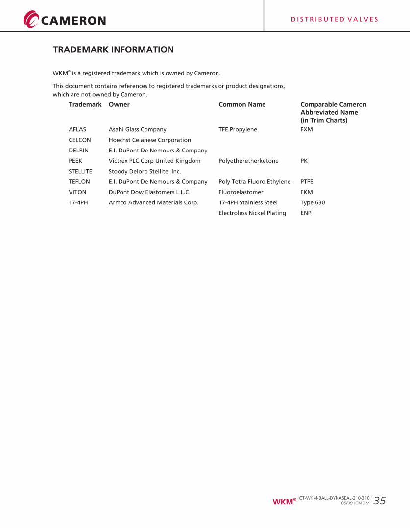
35
TRADEMARK INFORMATION
®WKM is a registered trademark which is owned by Cameron.
This document contains references to registered trademarks or product designations,
which are not owned by Cameron.
TrademarkAbbreviated Name(in Trim Charts)
AFLAS Asahi Glass Company TFE Propylene FXM
CELCON Hoechst Celanese Corporation
DELRIN E.I. DuPont De Nemours & Company
PEEK Victrex PLC Corp United Kingdom Polyetheretherketone PK
STELLITE Stoody Deloro Stellite, Inc.
TEFLON E.I. DuPont De Nemours & Company Poly Tetra Fluoro Ethylene PTFE
VITON DuPont Dow Elastomers L.L.C. Fluoroelastomer FKM
17-4PH Armco Advanced Materials Corp. 17-4PH Stainless Steel Type 630
Electroless Nickel Plating ENP
Owner Common Name Comparable Cameron
CT-WKM-BALL-DYNASEAL-210-31005/09-ION-3M
®WKM
D I S T R I B U T E D V A L V E S
NOTES
CT-WKM-BALL-DYNASEAL-210-31005/09-ION-3M
®WKM
D I S T R I B U T E D V A L V E S

D I S T R I B U T E D V A L V E S

D I S T R I B U T E D V A L V E S
Printed in Canada 05/09-ION-3M
For the most current contact and location information go to: www.c-a-m.com/valvesandmeasurement
VALVES & MEASUREMENT3250 Briarpark Drive, Suite 300Houston, Texas 77042USA Toll Free 800 323 9160
CT-WKM-BALL-DYNASEAL-210-310Rev. 1 05/09


![WKM® DynaSeal® 210 and 310 Floating Ball Valves1].pdf · WKM® DynaSeal® 210 and 310 Floating Ball Valves ... (environment) by the customer/user, Cameron can make technical recommendations](https://img.pdfslide.net/doc/110x75/5a7958af7f8b9ab9308c8b03/wkm-dynaseal-210-and-310-floating-ball-1pdfwkm-dynaseal-210-and-310-floating-ball.jpg)