Embed Size (px)
Citation preview
1
WLAN (802.11)
Renato Lo Cigno
www.disi.unitn.it/locigno/didattica/NC/
[email protected]: TLC Networks Group – Politecnico di Torino
Nomadic Communications – 802.11 2
...Copyright
Quest’opera è protetta dalla licenza Creative Commons NoDerivs-NonCommercial. Per vedere una copia di questalicenza, consultare: http://creativecommons.org/licenses/nd-nc/1.0/ oppure inviare una lettera a:Creative Commons, 559 Nathan Abbott Way, Stanford, California 94305, USA.
This work is licensed under the Creative Commons NoDerivs-NonCommercial License. To view a copy of this license, visit: http://creativecommons.org/licenses/nd-nc/1.0/or send a letter to Creative Commons, 559 Nathan Abbott Way, Stanford, California 94305, USA.
[email protected]: TLC Networks Group – Politecnico di Torino
Nomadic Communications – 802.11 3
IEEE 802.11
• Wireless LAN standard specifying a wireless interface between a client and a base station (or access point), as well as between wireless clients
• Defines the PHY and MAC layer (LLC layerdefined in 802.2)
• Physical Media: radio or diffused infrared
• Standardization process begun in 1990 and is still going on (1st release ’97, 2nd release ’99, then ’03, ’05, ...)
2
[email protected]: TLC Networks Group – Politecnico di Torino
Nomadic Communications – 802.11 4
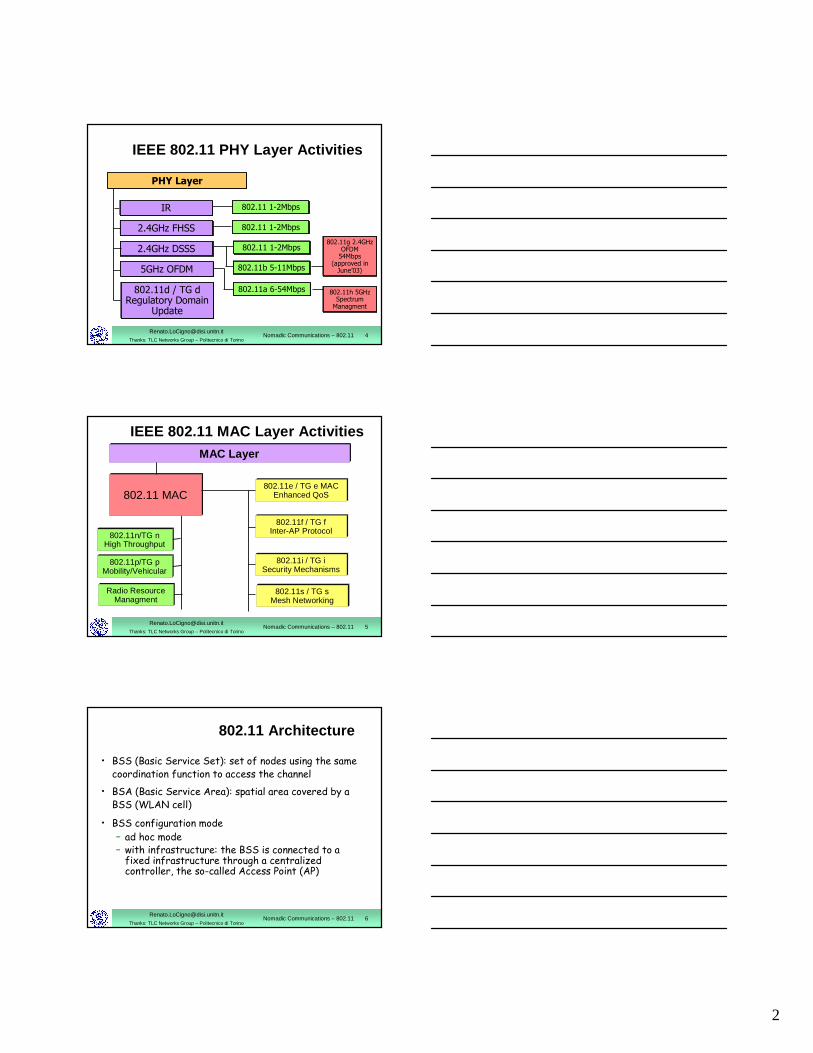
IEEE 802.11 PHY Layer Activities
PHY Layer
802.11 1-2Mbps
2.4GHz FHSS
2.4GHz DSSS
5GHz OFDM
802.11d / TG d Regulatory Domain
Update
802.11 1-2Mbps
802.11 1-2Mbps
802.11a 6-54Mbps
802.11g 2.4GHz OFDM
54Mbps(approved in
June’03)
802.11h 5GHz Spectrum
Managment
IR
802.11b 5-11Mbps
[email protected]: TLC Networks Group – Politecnico di Torino
Nomadic Communications – 802.11 5
IEEE 802.11 MAC Layer ActivitiesMAC Layer
802.11 MAC802.11e / TG e MAC
Enhanced QoS
802.11f / TG fInter-AP Protocol
802.11i / TG iSecurity Mechanisms
802.11n/TG nHigh Throughput
Radio ResourceManagment
802.11s / TG sMesh Networking
802.11p/TG pMobility/Vehicular
[email protected]: TLC Networks Group – Politecnico di Torino
Nomadic Communications – 802.11 6
802.11 Architecture
• BSS (Basic Service Set): set of nodes using the samecoordination function to access the channel
• BSA (Basic Service Area): spatial area covered by a BSS (WLAN cell)
• BSS configuration mode– ad hoc mode– with infrastructure: the BSS is connected to a fixed infrastructure through a centralizedcontroller, the so-called Access Point (AP)
3
[email protected]: TLC Networks Group – Politecnico di Torino
Nomadic Communications – 802.11 7
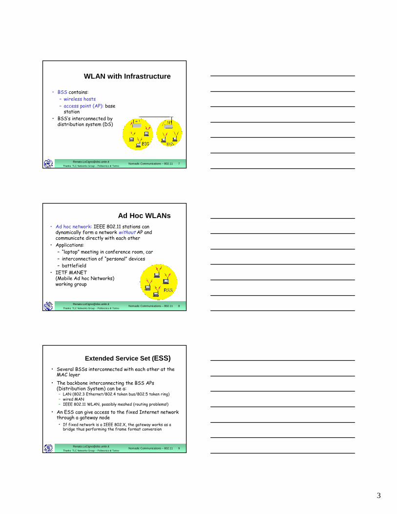
WLAN with Infrastructure
• BSS contains:
– wireless hosts
– access point (AP): base station
• BSS’s interconnected by distribution system (DS)
[email protected]: TLC Networks Group – Politecnico di Torino
Nomadic Communications – 802.11 8
Ad Hoc WLANs• Ad hoc network: IEEE 802.11 stations can
dynamically form a network without AP and communicate directly with each other
• Applications:
– “laptop” meeting in conference room, car
– interconnection of “personal” devices
– battlefield
• IETF MANET (Mobile Ad hoc Networks) working group
[email protected]: TLC Networks Group – Politecnico di Torino
Nomadic Communications – 802.11 9
• Several BSSs interconnected with each other at the MAC layer
• The backbone interconnecting the BSS APs(Distribution System) can be a:– LAN (802.3 Ethernet/802.4 token bus/802.5 token ring)– wired MAN – IEEE 802.11 WLAN, possibly meshed (routing problems!)
• An ESS can give access to the fixed Internet network through a gateway node• If fixed network is a IEEE 802.X, the gateway works as a
bridge thus performing the frame format conversion
Extended Service Set ( ESS)
4
[email protected]: TLC Networks Group – Politecnico di Torino
Nomadic Communications – 802.11 10
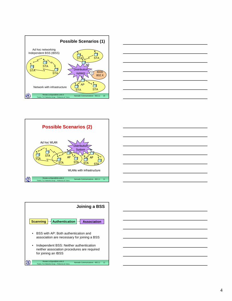
Possible Scenarios (1)
STA
STA
STA
Ad hoc networkingIndependent BSS (IBSS)
IEEE 802.X
STA
AP
AP
STANetwork with infrastructure
Distributionsystem
STA STA
[email protected]: TLC Networks Group – Politecnico di Torino
Nomadic Communications – 802.11 11
Possible Scenarios (2)
Ad hoc WLAN
STA
WLANs with infrastructure
Distribution
System
STA
APAP
STA STA
STASTA
[email protected]: TLC Networks Group – Politecnico di Torino
Nomadic Communications – 802.11 12
Joining a BSS
• BSS with AP: Both authentication and association are necessary for joining a BSS
• Independent BSS: Neither authentication neither association procedures are required for joining an IBSS
Scanning Authentication Association
5
[email protected]: TLC Networks Group – Politecnico di Torino
Nomadic Communications – 802.11 13
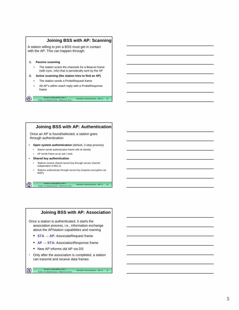
Joining BSS with AP: Scanning
1. Passive scanning
• The station scans the channels for a Beacon frame(with sync. info) that is periodically sent by the AP
2. Active scanning (the station tries to find an AP)
• The station sends a ProbeRequest frame
• All AP’s within reach reply with a ProbeResponse frame
A station willing to join a BSS must get in contact with the AP. This can happen through:
[email protected]: TLC Networks Group – Politecnico di Torino
Nomadic Communications – 802.11 14
Joining BSS with AP: Authentication
• Open system authentication (default, 2-step process)
• Station sends authentication frame with its identity
• AP sends frame as an ack / nack
• Shared key authentication
• Stations receive shared secret key through secure channelindependent of 802.11
• Stations authenticate through secret key (requires encryption via WEP)
Once an AP is found/selected, a station goesthrough authentication
[email protected]: TLC Networks Group – Politecnico di Torino
Nomadic Communications – 802.11 15
Joining BSS with AP: Association
Once a station is authenticated, it starts the association process, i.e., information exchangeabout the AP/station capabilities and roaming
� STA → AP: AssociateRequest frame
� AP → STA: AssociationResponse frame
� New AP informs old AP via DS
• Only after the association is completed, a station can transmit and receive data frames
6
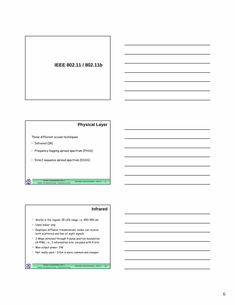
IEEE 802.11 / 802.11b
[email protected]: TLC Networks Group – Politecnico di Torino
Nomadic Communications – 802.11 17
Physical Layer
Three different access techniques:
• Infrared (IR)
• Frequency hopping spread spectrum (FHSS)
• Direct sequence spread spectrum (DSSS)
[email protected]: TLC Networks Group – Politecnico di Torino
Nomadic Communications – 802.11 18
Infrared
• Works in the regular IR LED range, i.e. 850-950 nm
• Used indoor only
• Employes diffusive transmissions, nodes can receive
both scattered and line-of-sight signals
• 2 Mbps obtained through 4-pulse position modulation
(4-PPM), i.e., 2 information bits encoded with 4 bits
• Max output power: 2W
• Not really used – IrDA is more common and cheaper
7
[email protected]: TLC Networks Group – Politecnico di Torino
Nomadic Communications – 802.11 19
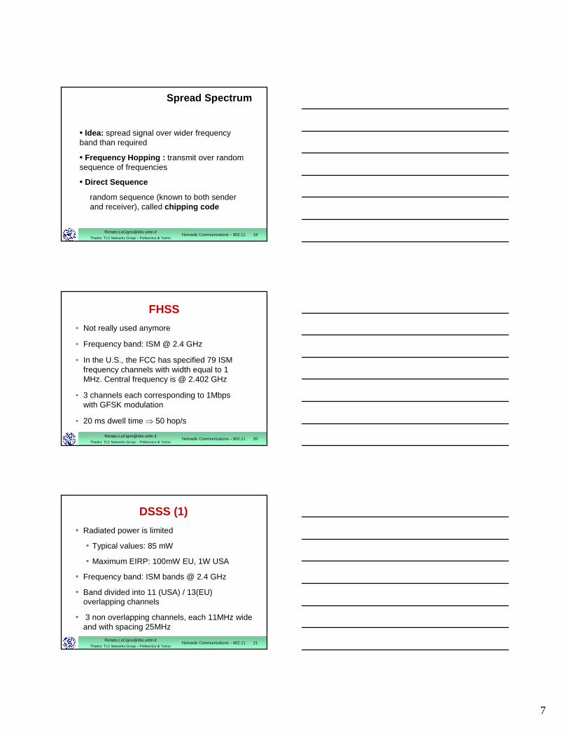
Spread Spectrum
• Idea: spread signal over wider frequencyband than required
• Frequency Hopping : transmit over random sequence of frequencies
• Direct Sequence
random sequence (known to both sender and receiver), called chipping code
[email protected]: TLC Networks Group – Politecnico di Torino
Nomadic Communications – 802.11 20
FHSS
• Not really used anymore
• Frequency band: ISM @ 2.4 GHz
• In the U.S., the FCC has specified 79 ISM frequency channels with width equal to 1 MHz. Central frequency is @ 2.402 GHz
• 3 channels each corresponding to 1Mbps with GFSK modulation
• 20 ms dwell time ⇒ 50 hop/s
[email protected]: TLC Networks Group – Politecnico di Torino
Nomadic Communications – 802.11 21
DSSS (1)
• Radiated power is limited
• Typical values: 85 mW
• Maximum EIRP: 100mW EU, 1W USA
• Frequency band: ISM bands @ 2.4 GHz
• Band divided into 11 (USA) / 13(EU) overlapping channels
• 3 non overlapping channels, each 11MHz wideand with spacing 25MHz
8
[email protected]: TLC Networks Group – Politecnico di Torino
Nomadic Communications – 802.11 22
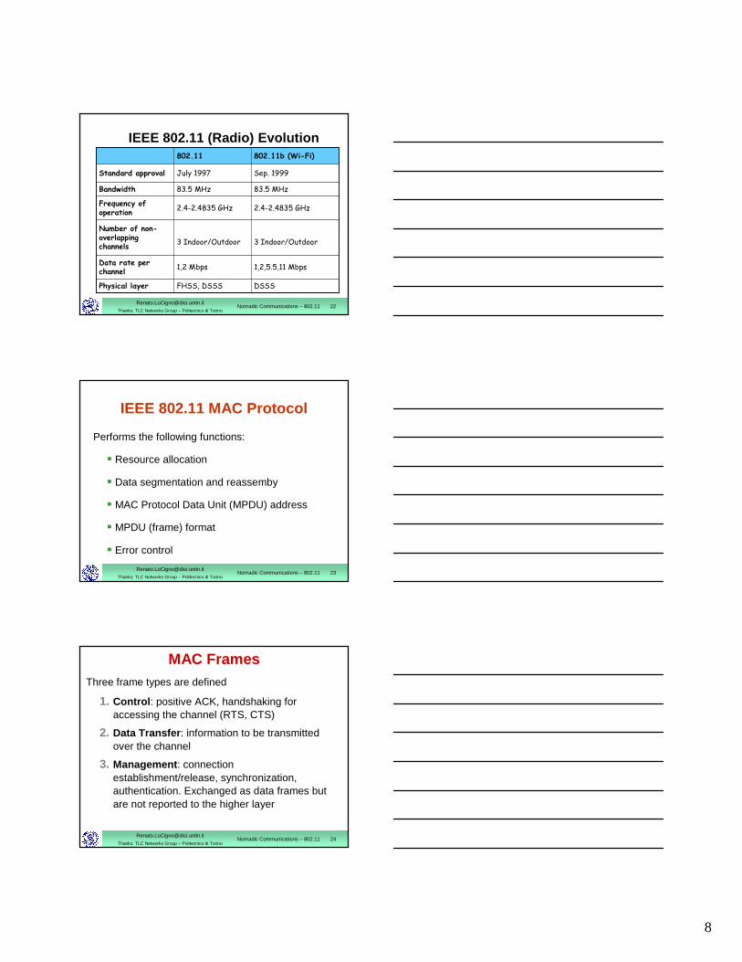
IEEE 802.11 (Radio) Evolution
DSSS
1,2,5.5,11 Mbps
3 Indoor/Outdoor
2.4-2.4835 GHz
83.5 MHz
Sep. 1999
802.11b (Wi-Fi)
FHSS, DSSSPhysical layer
83.5 MHzBandwidth
2.4-2.4835 GHzFrequency of operation
1,2 MbpsData rate per channel
3 Indoor/Outdoor
Number of non-overlappingchannels
July 1997Standard approval
802.11
[email protected]: TLC Networks Group – Politecnico di Torino
Nomadic Communications – 802.11 23
IEEE 802.11 MAC Protocol
Performs the following functions:
� Resource allocation
� Data segmentation and reassemby
� MAC Protocol Data Unit (MPDU) address
� MPDU (frame) format
� Error control
[email protected]: TLC Networks Group – Politecnico di Torino
Nomadic Communications – 802.11 24
MAC FramesThree frame types are defined
1. Control : positive ACK, handshaking foraccessing the channel (RTS, CTS)
2. Data Transfer : information to be transmittedover the channel
3. Management : connection establishment/release, synchronization, authentication. Exchanged as data frames butare not reported to the higher layer
9
[email protected]: TLC Networks Group – Politecnico di Torino
Nomadic Communications – 802.11 25
Data Transfer• Asynchronous data transfer for delay-tolerant
traffic (like file transfer)
� DCF (Distributed Coordination Function)
• Synchronous data transfer for real-time traffic (like audio and video)
� PCF (Point Coordination Function): based on the polling of the stations and controlled by the AP (PC)
� Its implementation is optional (not really implemented)
[email protected]: TLC Networks Group – Politecnico di Torino
Nomadic Communications – 802.11 26
Time Slot• Time is divided into intervals, called slots
• A slot is the system unit time and its duration depends on the implementation of the physical layer
• 802.11b: 20µs
• Stations are synchronized with the AP in the infrastructure mode and among each other in the ad hoc mode ⇒ the system is synchronous
• Synchornization maintained through Beaconframes
[email protected]: TLC Networks Group – Politecnico di Torino
Nomadic Communications – 802.11 27
IFS
• Interframe space (IFS)• time interval between frame transmissions• used to establish priority in accessing the
channel• 4 types of IFS:
� Short IFS (SIFS)� Point coordination IFS (PIFS) >SIFS� Distributed IFS (DIFS) >PIFS� Extended IFS (EIFS) > DIFS
• Duration depends on physical level implementation
10
[email protected]: TLC Networks Group – Politecnico di Torino
Nomadic Communications – 802.11 28
Short IFS (SIFS)
• To separate transmissions belonging to the same dialogue
• Associated to the highest priority
• Its duration depends on:
� Propagation time over the channel
� Time to convey the information from the PHY to the MAC layer
� Radio switch time from TX to RX mode
• 802.11b: 10µs
[email protected]: TLC Networks Group – Politecnico di Torino
Nomadic Communications – 802.11 29
Point Coordination IFS (PIFS)
• Used to give priority access to Point Coordinator(PC)
• Only a PC can access the channel betweenSIFS and DIFS
• PIFS=SIFS + 1 time slot
[email protected]: TLC Networks Group – Politecnico di Torino
Nomadic Communications – 802.11 30
Distributed IFS (DIFS)
• Used by stations waiting for a free channel to contend
• Set to: PIFS + 1 time slot
11
[email protected]: TLC Networks Group – Politecnico di Torino
Nomadic Communications – 802.11 31
Extended IFS (EIFS)
• Used by every station when the PHY layer notifies the MAC layer that a transmission has not been correctly received
• Avoids that stations with bad channels disrupt other stations’ performance
• Forces fairness in the access is one station does not receive an ACK (e.g. hidden terminal)
• Reduce the priority of the first retransmission (indeed make it equal to all others)
• Set to: DIFS + 1 ACK slot
[email protected]: TLC Networks Group – Politecnico di Torino
Nomadic Communications – 802.11 32
DCF Access Scheme
[email protected]: TLC Networks Group – Politecnico di Torino
Nomadic Communications – 802.11 33
Basic Characteristics• Its implementation is mandatory
• DCF is based on the Carrier Sense Multiple Access/Collision Avoidance (CSMA/CA) scheme:
� stations that have data to transmit contend for accessing the channel
� a station has to repeat the contention procedure every time it has a new data frame to transmit
12
[email protected]: TLC Networks Group – Politecnico di Torino
Nomadic Communications – 802.11 34
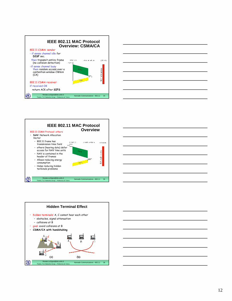
IEEE 802.11 MAC Protocol Overview: CSMA/CA
802.11 CSMA: sender
- if sense channel idle for DISF sec.
then transmit entire frame (no collision detection)
-if sense channel busy then random access over a contention window CWmin(CA)
802.11 CSMA receiver:
if received OK
return ACK after SIFS
[email protected]: TLC Networks Group – Politecnico di Torino
Nomadic Communications – 802.11 35
IEEE 802.11 MAC Protocol Overview
802.11 CSMA Protocol: others
• NAV: Network Allocation Vector
– 802.11 frame has transmission time field
– others (hearing data) defer access for NAV time units
– NAV is contained in the header of frames
– Allows reducing energy consumption
– Helps reducing hidden terminals problems
[email protected]: TLC Networks Group – Politecnico di Torino
Nomadic Communications – 802.11 36
Hidden Terminal Effect
• hidden terminals: A, C cannot hear each other
– obstacles, signal attenuation
– collisions at B
• goal: avoid collisions at B
• CSMA/CA with handshaking
13
[email protected]: TLC Networks Group – Politecnico di Torino
Nomadic Communications – 802.11 37
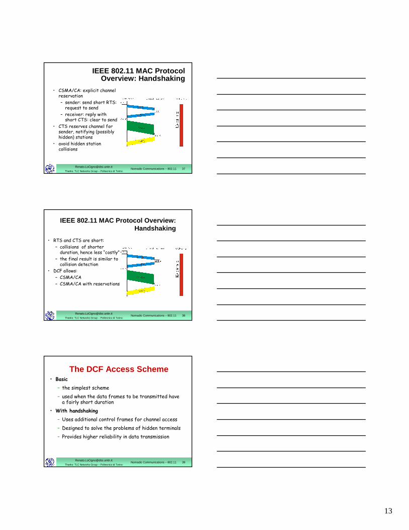
IEEE 802.11 MAC Protocol Overview: Handshaking
• CSMA/CA: explicit channel reservation
– sender: send short RTS: request to send
– receiver: reply with short CTS: clear to send
• CTS reserves channel for sender, notifying (possibly hidden) stations
• avoid hidden station collisions
[email protected]: TLC Networks Group – Politecnico di Torino
Nomadic Communications – 802.11 38
• RTS and CTS are short:
– collisions of shorter duration, hence less “costly”
– the final result is similar to collision detection
• DCF allows:
– CSMA/CA
– CSMA/CA with reservations
IEEE 802.11 MAC Protocol Overview: Handshaking
[email protected]: TLC Networks Group – Politecnico di Torino
Nomadic Communications – 802.11 39
The DCF Access Scheme• Basic
– the simplest scheme
– used when the data frames to be transmitted have a fairly short duration
• With handshaking
– Uses additional control frames for channel access
– Designed to solve the problems of hidden terminals
– Provides higher reliability in data transmission
14
[email protected]: TLC Networks Group – Politecnico di Torino
Nomadic Communications – 802.11 40
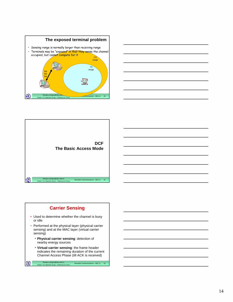
The exposed terminal problem
• Sensing range is normally larger than receiving range
• Terminals may be “exposed” in that they sense the channel occupied, but cannot compete for it
blablabla
TXrange
CSrange
[email protected]: TLC Networks Group – Politecnico di Torino
Nomadic Communications – 802.11 41
DCFThe Basic Access Mode
[email protected]: TLC Networks Group – Politecnico di Torino
Nomadic Communications – 802.11 42
Carrier Sensing
• Used to determine whether the channel is busy or idle
• Performed at the physical layer (physical carrier sensing) and at the MAC layer (virtual carrier sensing)
� Physical carrier sensing : detection of nearby energy sources
� Virtual carrier sensing : the frame header indicates the remaining duration of the current Channel Access Phase (till ACK is received)
15
[email protected]: TLC Networks Group – Politecnico di Torino
Nomadic Communications – 802.11 43
Network Allocation Vector (NAV)
• Used by the stations nearby the transmitter to store the duration of the frame that is occupying the channel
• The channel will become idle when the NAV expires
• Upon the NAV expiration, stations that have data to transmit listen to the channel again
[email protected]: TLC Networks Group – Politecnico di Torino
Nomadic Communications – 802.11 44
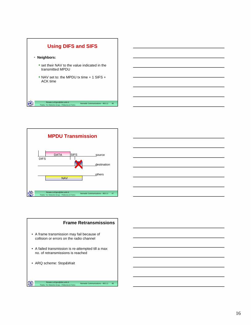
Using DIFS and SIFS
• Transmitter:
� senses the channel
� if the channel is idle, it waits a time equal to DIFS
� if the channel remains idle for DIFS, it transmits its MPDU
[email protected]: TLC Networks Group – Politecnico di Torino
Nomadic Communications – 802.11 45
Using DIFS and SIFS
• Receiver:
� computes the checksum thus verifying whether the transmission is correct
� if so, it sends an ACK after a time equal to SIFS
� it should always transmit an ACK with a rate less than or equal to the one used by the transmitter and no larger than 2Mbit/s
16
[email protected]: TLC Networks Group – Politecnico di Torino
Nomadic Communications – 802.11 46
Using DIFS and SIFS
• Neighbors:
� set their NAV to the value indicated in the transmitted MPDU
� NAV set to: the MPDU tx time + 1 SIFS + ACK time
[email protected]: TLC Networks Group – Politecnico di Torino
Nomadic Communications – 802.11 47
DIFSSIFS
ACK
DATA
NAV
source
destination
others
MPDU Transmission
[email protected]: TLC Networks Group – Politecnico di Torino
Nomadic Communications – 802.11 48
Frame Retransmissions
• A frame transmission may fail because of collision or errors on the radio channel
• A failed transmission is re-attempted till a max no. of retransmissions is reached
• ARQ scheme: Stop&Wait
17
[email protected]: TLC Networks Group – Politecnico di Torino
Nomadic Communications – 802.11 49
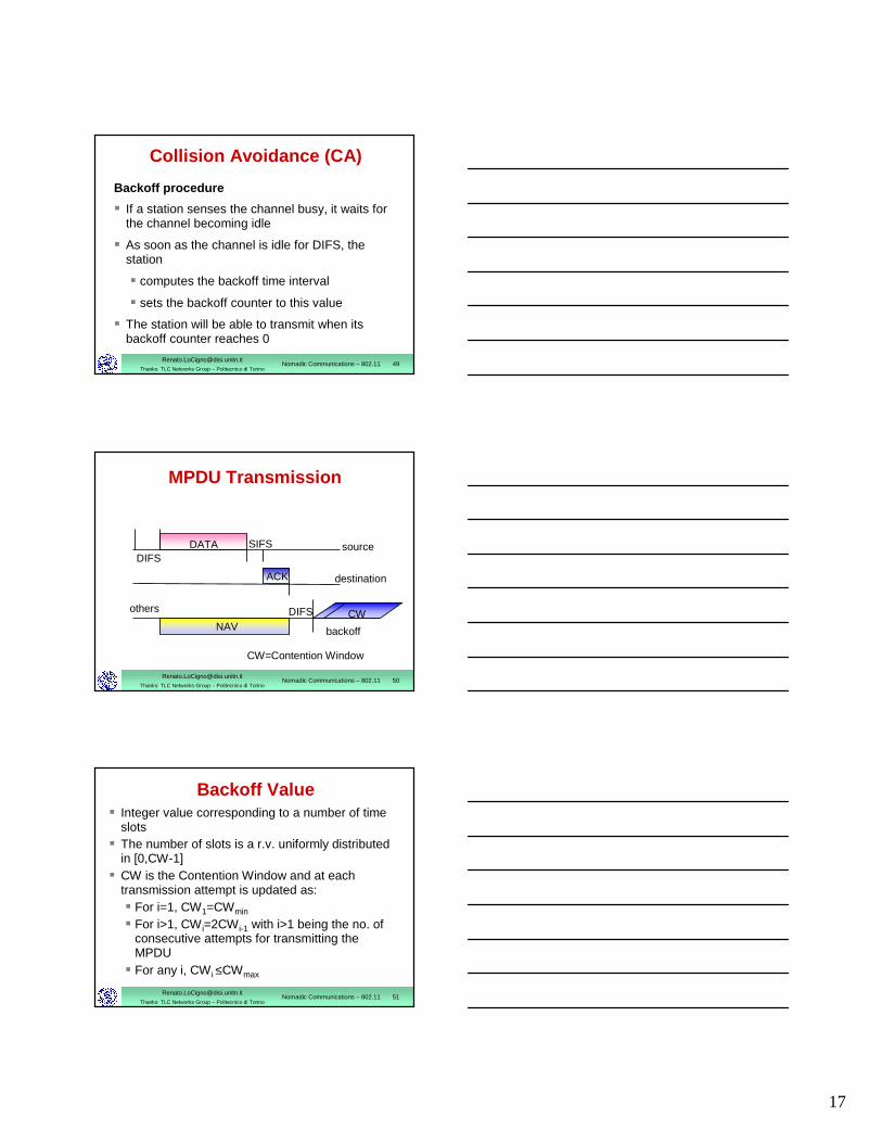
Collision Avoidance (CA)
Backoff procedure
� If a station senses the channel busy, it waits for the channel becoming idle
� As soon as the channel is idle for DIFS, the station
� computes the backoff time interval
� sets the backoff counter to this value
� The station will be able to transmit when its backoff counter reaches 0
[email protected]: TLC Networks Group – Politecnico di Torino
Nomadic Communications – 802.11 50
DIFSSIFS
ACK
DATA
DIFSNAV
CW
source
destination
others
backoff
MPDU Transmission
CW=Contention Window
[email protected]: TLC Networks Group – Politecnico di Torino
Nomadic Communications – 802.11 51
Backoff Value� Integer value corresponding to a number of time
slots� The number of slots is a r.v. uniformly distributed
in [0,CW-1]� CW is the Contention Window and at each
transmission attempt is updated as:� For i=1, CW1=CWmin
� For i>1, CW i=2CWi-1 with i>1 being the no. of consecutive attempts for transmitting the MPDU
� For any i, CW i ≤CWmax
18
[email protected]: TLC Networks Group – Politecnico di Torino
Nomadic Communications – 802.11 52
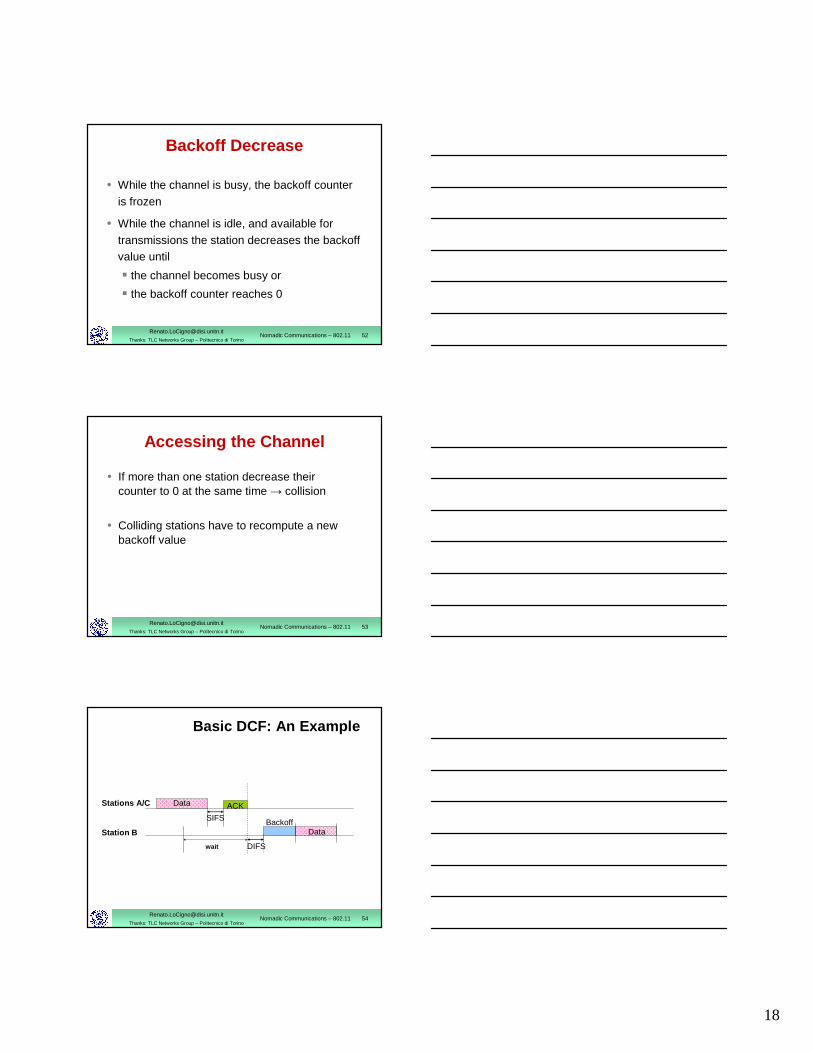
Backoff Decrease
• While the channel is busy, the backoff counter is frozen
• While the channel is idle, and available for transmissions the station decreases the backoffvalue until
� the channel becomes busy or
� the backoff counter reaches 0
[email protected]: TLC Networks Group – Politecnico di Torino
Nomadic Communications – 802.11 53
• If more than one station decrease theircounter to 0 at the same time → collision
• Colliding stations have to recompute a new backoff value
Accessing the Channel
[email protected]: TLC Networks Group – Politecnico di Torino
Nomadic Communications – 802.11 54
Basic DCF: An Example
Data
SIFS
DIFS
Data
Stations A/C
Station B
ACK
Backoff
wait
19
[email protected]: TLC Networks Group – Politecnico di Torino
Nomadic Communications – 802.11 55
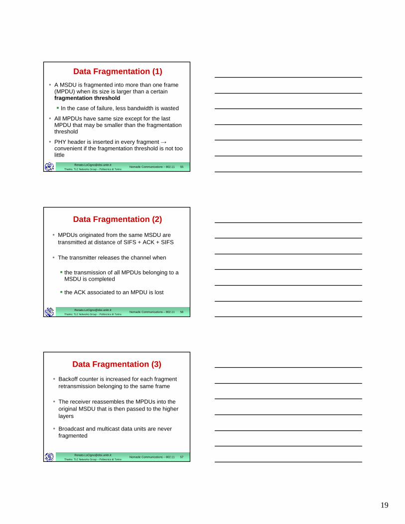
Data Fragmentation (1)
• A MSDU is fragmented into more than one frame (MPDU) when its size is larger than a certain fragmentation threshold
� In the case of failure, less bandwidth is wasted
• All MPDUs have same size except for the last MPDU that may be smaller than the fragmentation threshold
• PHY header is inserted in every fragment →convenient if the fragmentation threshold is not too little
[email protected]: TLC Networks Group – Politecnico di Torino
Nomadic Communications – 802.11 56
• MPDUs originated from the same MSDU are transmitted at distance of SIFS + ACK + SIFS
• The transmitter releases the channel when
� the transmission of all MPDUs belonging to a MSDU is completed
� the ACK associated to an MPDU is lost
Data Fragmentation (2)
[email protected]: TLC Networks Group – Politecnico di Torino
Nomadic Communications – 802.11 57
• Backoff counter is increased for each fragment retransmission belonging to the same frame
• The receiver reassembles the MPDUs into the original MSDU that is then passed to the higher layers
• Broadcast and multicast data units are never fragmented
Data Fragmentation (3)
20
[email protected]: TLC Networks Group – Politecnico di Torino
Nomadic Communications – 802.11 58
Recontending for the Channel
• A station recontends for the channel when
� it has completed the transmission of anMPDU but still has data to transmit
� a MPDU transmission fails and the MPDU must be retransmitted
• Before recontending the channel after a successful transmission, a station must perform a backoff procedure with CWmin
[email protected]: TLC Networks Group – Politecnico di Torino
Nomadic Communications – 802.11 59
DCFAccess with handshaking
[email protected]: TLC Networks Group – Politecnico di Torino
Nomadic Communications – 802.11 60
Access with Handshake
• Used to reserve the channel
• Why?
– Hidden stations
– Colliding stations keep transmitting their MPDU; the larger the MPDU involved in the collision, the more bandwidth is wasted
– Need to avoid collisions, especially when frame is large
– Particularly useful when a large no. of STAs contend for the channel
21
[email protected]: TLC Networks Group – Politecnico di Torino
Nomadic Communications – 802.11 61
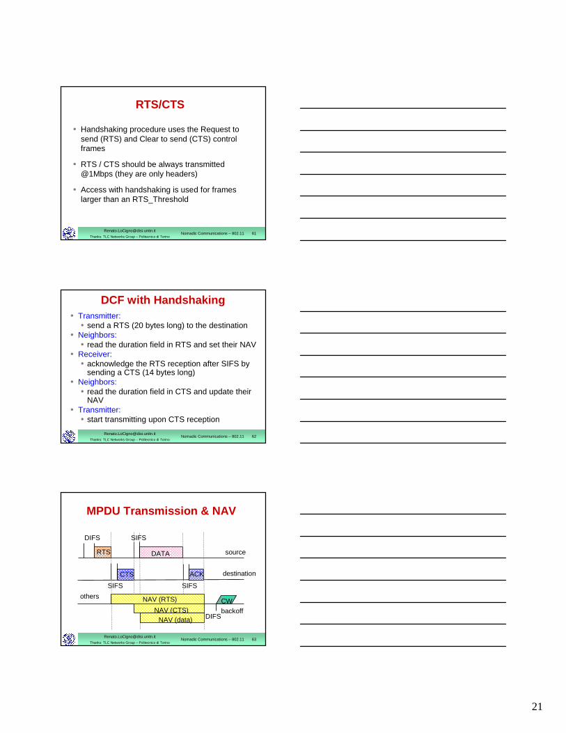
RTS/CTS
• Handshaking procedure uses the Request to send (RTS) and Clear to send (CTS) control frames
• RTS / CTS should be always transmitted @1Mbps (they are only headers)
• Access with handshaking is used for frameslarger than an RTS_Threshold
[email protected]: TLC Networks Group – Politecnico di Torino
Nomadic Communications – 802.11 62
DCF with Handshaking• Transmitter:
• send a RTS (20 bytes long) to the destination• Neighbors:
• read the duration field in RTS and set their NAV• Receiver:
• acknowledge the RTS reception after SIFS by sending a CTS (14 bytes long)
• Neighbors:• read the duration field in CTS and update their
NAV• Transmitter:
• start transmitting upon CTS reception
[email protected]: TLC Networks Group – Politecnico di Torino
Nomadic Communications – 802.11 63
backoff
source
destination
others
DIFS
ACK
DATA
CW
RTS
CTS
DIFS
SIFS
SIFS SIFS
NAV (RTS)
NAV (CTS)NAV (data)
MPDU Transmission & NAV
22
[email protected]: TLC Networks Group – Politecnico di Torino
Nomadic Communications – 802.11 64
PCFCentralized access scheme
[email protected]: TLC Networks Group – Politecnico di Torino
Nomadic Communications – 802.11 65
Basic Characteristics
• Used for services with QoS requirements, itprovides a contention-free access to the channel
• Needs a Point Coordination (PC) that polls the stations → it can be implemented in networks with infrastructure only (AP=PC)
• Stations enabled to operate under the PCF mode are said to be CF-aware (CF=Contention Free)
[email protected]: TLC Networks Group – Politecnico di Torino
Nomadic Communications – 802.11 66
PCF
• Stations declare their participation in the CF phase in the Association Request
• PC builds the polling list based on the receivedrequests
• Polling list is static
• Implementation of the polling list and tables are left to the system operator
23
[email protected]: TLC Networks Group – Politecnico di Torino
Nomadic Communications – 802.11 67
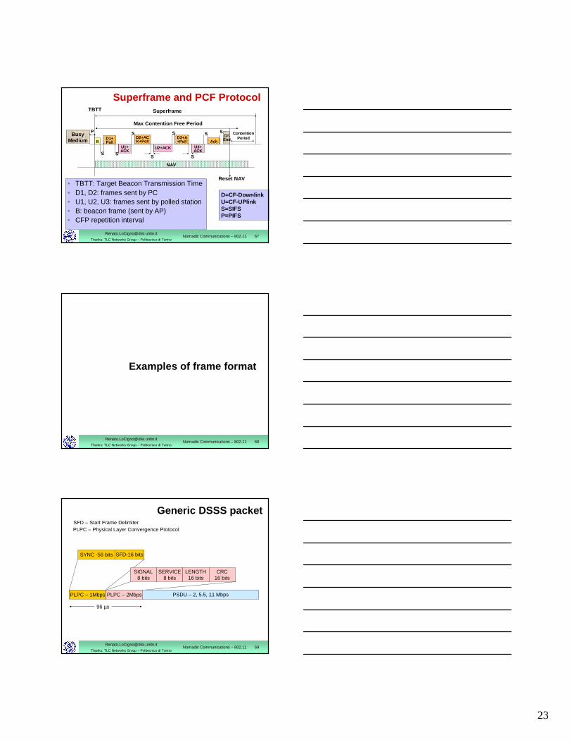
Superframe and PCF Protocol
D=CF-Downlink U=CF-UPlinkS=SIFSP=PIFS
U1+ACK
AckD1+ Poll
NAV
BusyMedium
D2+ACK+Poll
U2+ACK U3+ ACK
P S S
SS S
SD3+A+Poll
ContentionPeriod
Reset NAV
Superframe
Max Contention Free Period
SCF-EndB
S
TBTT
• TBTT: Target Beacon Transmission Time• D1, D2: frames sent by PC• U1, U2, U3: frames sent by polled station• B: beacon frame (sent by AP)• CFP repetition interval
[email protected]: TLC Networks Group – Politecnico di Torino
Nomadic Communications – 802.11 68
Examples of frame format
[email protected]: TLC Networks Group – Politecnico di Torino
Nomadic Communications – 802.11 69
Generic DSSS packet
SYNC -56 bits SFD-16 bits
SFD – Start Frame Delimiter
PLPC – 1Mbps
PLPC – Physical Layer Convergence Protocol
PLPC – 2Mbps
SIGNAL8 bits
SERVICE8 bits
LENGTH16 bits
CRC16 bits
PSDU – 2, 5.5, 11 Mbps
96 µs
24
[email protected]: TLC Networks Group – Politecnico di Torino
Nomadic Communications – 802.11 70
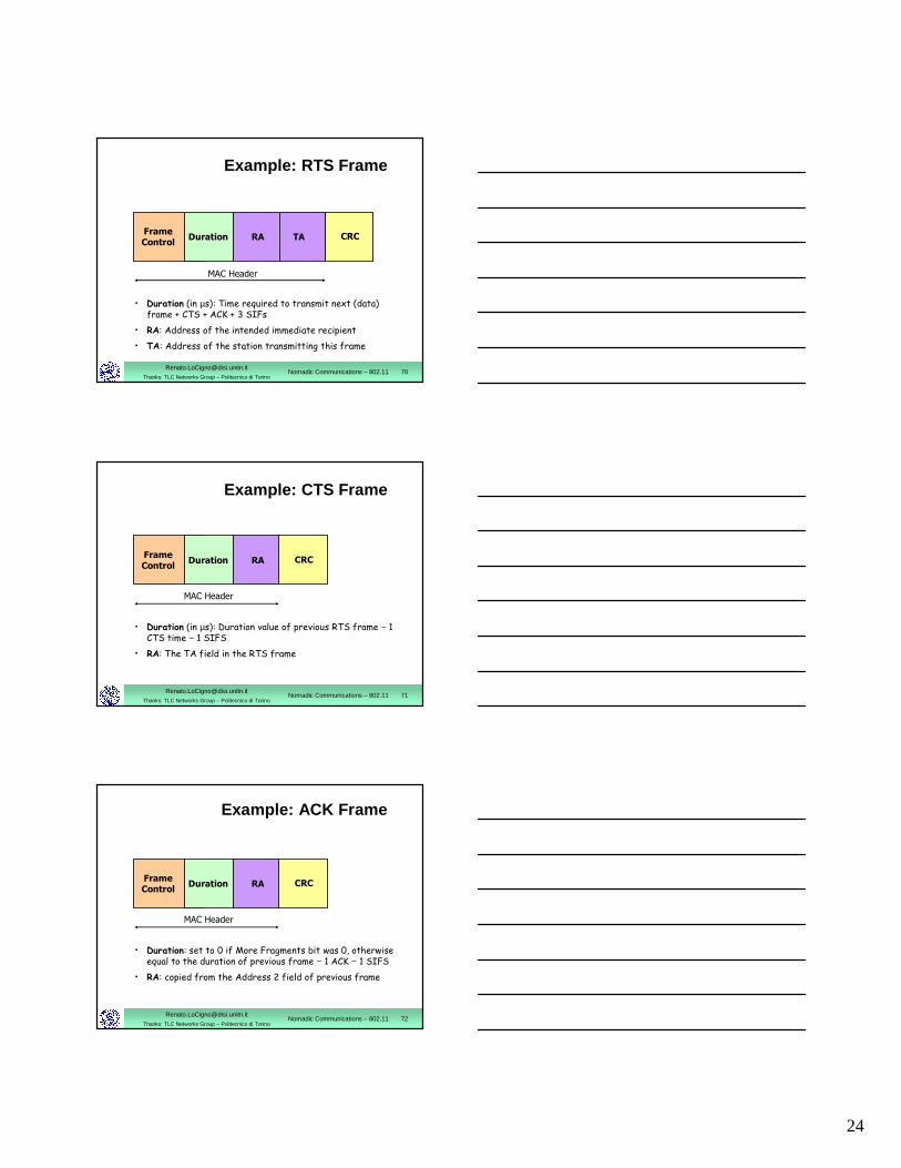
Example: RTS Frame
• Duration (in µs): Time required to transmit next (data) frame + CTS + ACK + 3 SIFs
• RA: Address of the intended immediate recipient
• TA: Address of the station transmitting this frame
FrameControl
Duration RA CRCTA
MAC Header
[email protected]: TLC Networks Group – Politecnico di Torino
Nomadic Communications – 802.11 71
Example: CTS Frame
• Duration (in µs): Duration value of previous RTS frame − 1 CTS time − 1 SIFS
• RA: The TA field in the RTS frame
FrameControl
Duration RA CRC
MAC Header
[email protected]: TLC Networks Group – Politecnico di Torino
Nomadic Communications – 802.11 72
Example: ACK Frame
• Duration: set to 0 if More Fragments bit was 0, otherwiseequal to the duration of previous frame − 1 ACK − 1 SIFS
• RA: copied from the Address 2 field of previous frame
FrameControl
Duration RA CRC
MAC Header
25
[email protected]: TLC Networks Group – Politecnico di Torino
Nomadic Communications – 802.11 73
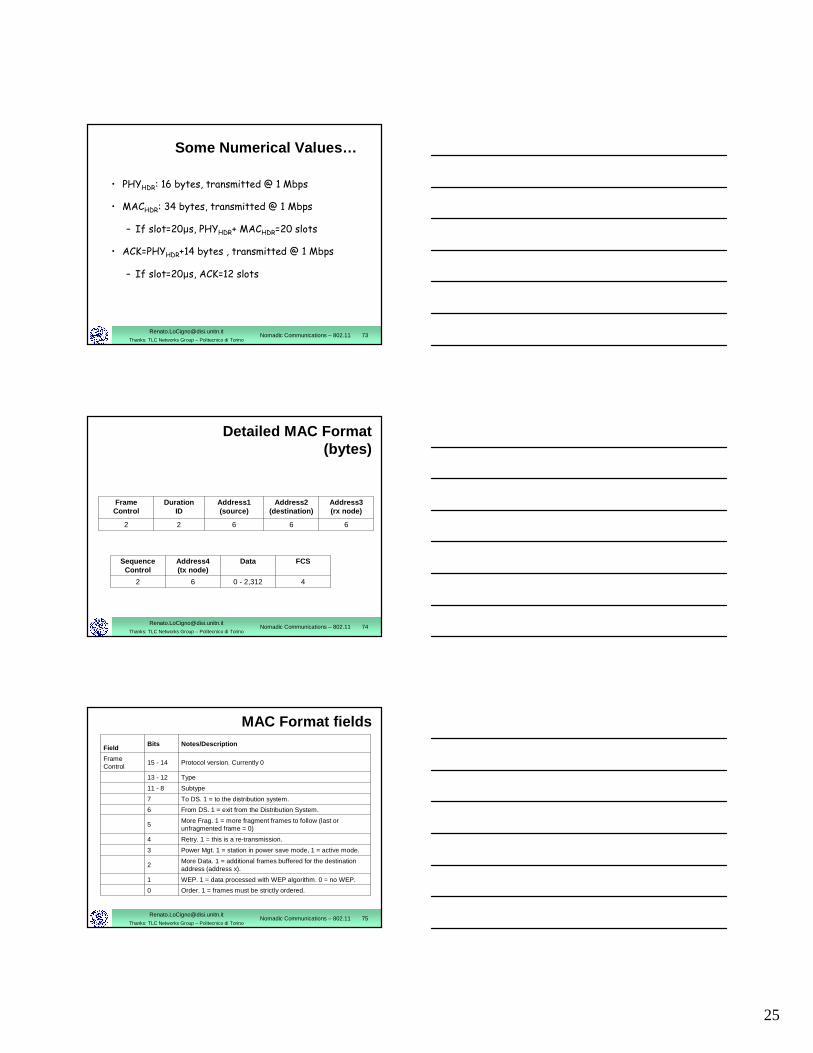
Some Numerical Values…
• PHYHDR: 16 bytes, transmitted @ 1 Mbps
• MACHDR: 34 bytes, transmitted @ 1 Mbps
– If slot=20µs, PHYHDR+ MACHDR=20 slots
• ACK=PHYHDR+14 bytes , transmitted @ 1 Mbps
– If slot=20µs, ACK=12 slots
[email protected]: TLC Networks Group – Politecnico di Torino
Nomadic Communications – 802.11 74
Detailed MAC Format(bytes)
66622
Address3(rx node)
Address2(destination)
Address1(source)
Duration ID
FrameControl
40 - 2,31262
FCSDataAddress4(tx node)
Sequence Control
[email protected]: TLC Networks Group – Politecnico di Torino
Nomadic Communications – 802.11 75
MAC Format fields
Order. 1 = frames must be strictly ordered.0
WEP. 1 = data processed with WEP algorithm. 0 = no WEP.1
More Data. 1 = additional frames buffered for the destination address (address x).
2
Power Mgt. 1 = station in power save mode, 1 = active mode.3
Retry. 1 = this is a re-transmission.4
More Frag. 1 = more fragment frames to follow (last or unfragmented frame = 0)
5
From DS. 1 = exit from the Distribution System.6
To DS. 1 = to the distribution system.7
Subtype11 - 8
Type13 - 12
Protocol version. Currently 015 - 14FrameControl
Notes/DescriptionBitsField
26
[email protected]: TLC Networks Group – Politecnico di Torino
Nomadic Communications – 802.11 76
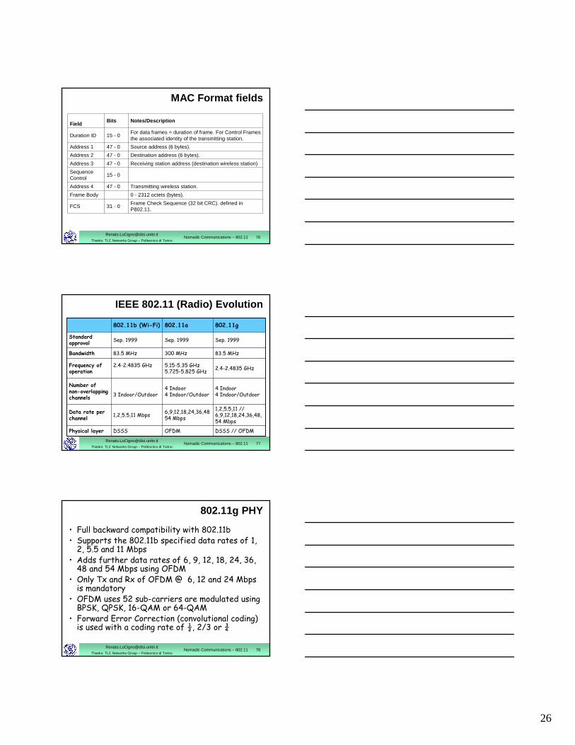
MAC Format fields
Frame Check Sequence (32 bit CRC). defined in P802.11.
31 - 0FCS
0 - 2312 octets (bytes).Frame Body
Transmitting wireless station.47 - 0Address 4
15 - 0Sequence Control
Receiving station address (destination wireless station)47 - 0Address 3
Destination address (6 bytes).47 - 0Address 2
Source address (6 bytes).47 - 0Address 1
For data frames = duration of frame. For Control Frames the associated identity of the transmitting station.
15 - 0Duration ID
Notes/DescriptionBitsField
[email protected]: TLC Networks Group – Politecnico di Torino
Nomadic Communications – 802.11 77
IEEE 802.11 (Radio) Evolution
OFDM
6,9,12,18,24,36,48 54 Mbps
4 Indoor4 Indoor/Outdoor
5.15-5.35 GHz5.725-5.825 GHz
300 MHz
Sep. 1999
802.11a
DSSS
1,2,5.5,11 Mbps
3 Indoor/Outdoor
2.4-2.4835 GHz
83.5 MHz
Sep. 1999
802.11b (Wi-Fi)
DSSS // OFDM
1,2,5.5,11 // 6,9,12,18,24,36,48,54 Mbps
4 Indoor4 Indoor/Outdoor
2.4-2.4835 GHz
83.5 MHz
Sep. 1999
802.11g
Physical layer
Bandwidth
Frequency of operation
Data rate per channel
Number of non-overlappingchannels
Standard approval
[email protected]: TLC Networks Group – Politecnico di Torino
Nomadic Communications – 802.11 78
802.11g PHY
• Full backward compatibility with 802.11b • Supports the 802.11b specified data rates of 1, 2, 5.5 and 11 Mbps
• Adds further data rates of 6, 9, 12, 18, 24, 36, 48 and 54 Mbps using OFDM
• Only Tx and Rx of OFDM @ 6, 12 and 24 Mbps is mandatory
• OFDM uses 52 sub-carriers are modulated using BPSK, QPSK, 16-QAM or 64-QAM
• Forward Error Correction (convolutional coding) is used with a coding rate of ½, 2/3 or ¾
27
[email protected]: TLC Networks Group – Politecnico di Torino
Nomadic Communications – 802.11 79
802.11g PHY
• Improved data rate is paid for with a smaller transmission range
• Improved data rates apply only to the payload: useless with small packets (60-80% of Internet packets are < than 100 bytes!)
• The overall performance is heavily influenced by the “worst channel syndrome”
• 802.11 MAC shares the channel based on access rounds not time