Embed Size (px)
Citation preview
December 2015 DocID028427 Rev 1 1/21
www.st.com
AN4772 Application note
wM-Bus (2013) firmware stack overview
Introduction M-Bus (meter bus) is a common automatic meter reader (AMR) standard for remote energy meter reading in compliance with European standard (EN 13757-2 physical and link layer and EN 13757-3 application layer). M-Bus is also compliant with the European Standard EN 1434 on heat meters.
The M-Bus interface is based on the very cost effective two-wire, twist cable transmission, and is compatible with all network topologies (linear, star, etc.) except ring networks. When queried, meters send their data to a concentrator from which the data can be read locally or remotely.
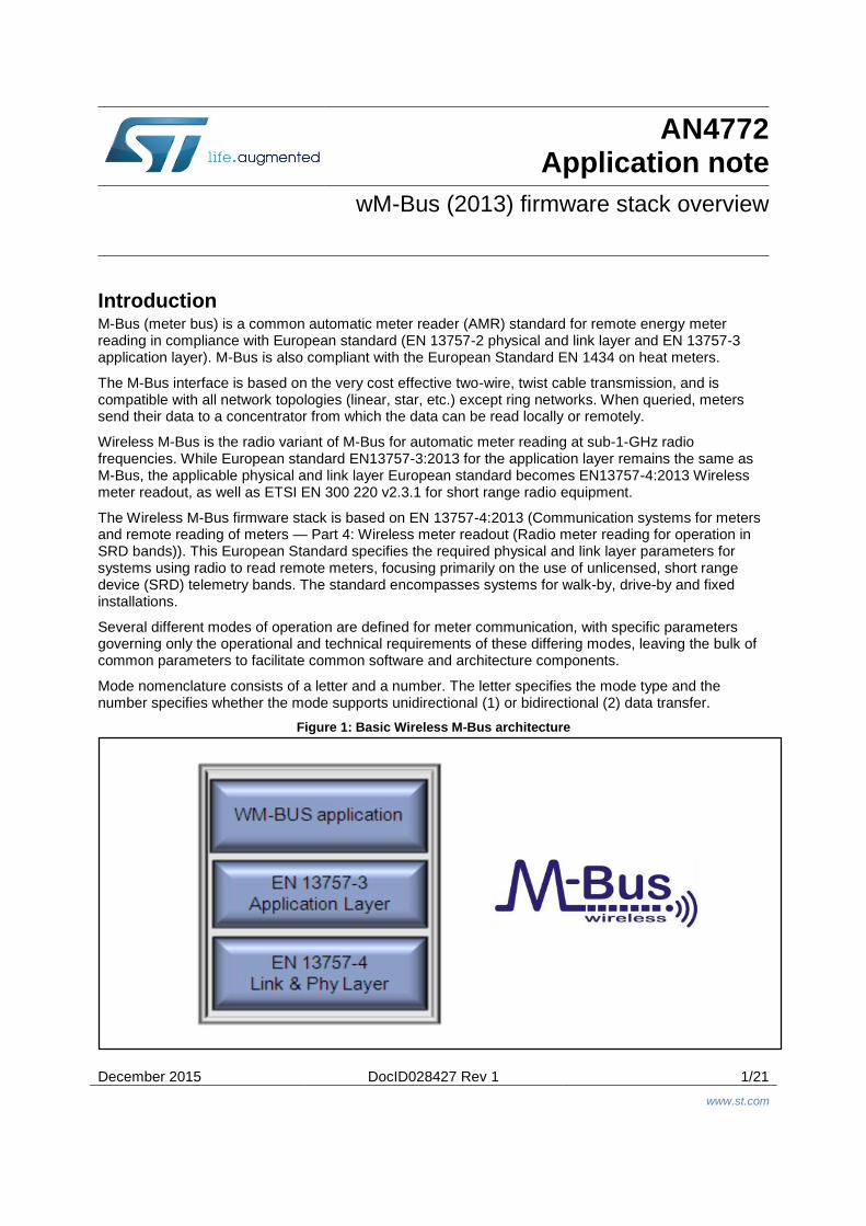
Wireless M-Bus is the radio variant of M-Bus for automatic meter reading at sub-1-GHz radio frequencies. While European standard EN13757-3:2013 for the application layer remains the same as M-Bus, the applicable physical and link layer European standard becomes EN13757-4:2013 Wireless meter readout, as well as ETSI EN 300 220 v2.3.1 for short range radio equipment.
The Wireless M-Bus firmware stack is based on EN 13757-4:2013 (Communication systems for meters and remote reading of meters — Part 4: Wireless meter readout (Radio meter reading for operation in SRD bands)). This European Standard specifies the required physical and link layer parameters for systems using radio to read remote meters, focusing primarily on the use of unlicensed, short range device (SRD) telemetry bands. The standard encompasses systems for walk-by, drive-by and fixed installations.
Several different modes of operation are defined for meter communication, with specific parameters governing only the operational and technical requirements of these differing modes, leaving the bulk of common parameters to facilitate common software and architecture components.
Mode nomenclature consists of a letter and a number. The letter specifies the mode type and the number specifies whether the mode supports unidirectional (1) or bidirectional (2) data transfer.
Figure 1: Basic Wireless M-Bus architecture
Contents AN4772
2/21 DocID028427 Rev 1
Contents
1 Definitions, acronyms and abbreviations ...................................... 7
2 Hardware platform ........................................................................... 8
2.1 SPIRIT1 ............................................................................................ 8
2.1.1 SPIRIT1 function: ............................................................................... 8
2.2 ST’s ultra-low power EnergyLite™ MCU family ................................. 9
2.2.1 STM32L function: ............................................................................... 9
3 Wireless M-Bus protocol overview .............................................. 10
3.1 wM-Bus modes ............................................................................... 10
3.1.1 Stationary mode (S Mode) ............................................................... 11
3.1.2 Frequent transmit mode (T Mode) .................................................... 11
3.1.3 Frequent receive mode (R2 Mode) .................................................. 11
3.1.4 Narrowband VHF mode (N-Mode) ................................................... 11
3.1.5 Frequent receive and transmit mode (F-Mode) ................................ 11
3.1.6 Compact Mode (C-Mode) ................................................................. 12
4 Wireless M-Bus physical layer ..................................................... 13
4.1 Frame structure ............................................................................... 13
4.1.1 Preamble .......................................................................................... 13
4.1.2 Payload ............................................................................................. 13
4.1.3 Postamble (trailer) ............................................................................ 13
4.2 Physical layer files ........................................................................... 13
5 Wireless M-Bus link layer ............................................................. 14
5.1 Data link layer functions .................................................................. 14
5.2 Link layer specification .................................................................... 14
5.2.1 Frame format A ................................................................................. 14
5.2.2 Frame format B ................................................................................. 14
5.2.3 The L-field ......................................................................................... 15
5.2.4 The C-Field ....................................................................................... 15
5.2.5 Manufacturer ID (M-field).................................................................. 15
5.2.6 Address (A-field) ............................................................................... 15
5.2.7 CI-field .............................................................................................. 16
5.2.8 Data field .......................................................................................... 16
5.2.9 Cyclic redundancy check (CRC-field) ............................................... 16
5.3 Link layer firmware implementation ................................................. 16
5.3.1 File description ................................................................................. 16
5.3.2 State machine flow structure ............................................................ 16

AN4772 Contents
DocID028427 Rev 1 3/21
5.4 Application layer dependent parameters ......................................... 18
6 Revision history ............................................................................ 20
List of tables AN4772
4/21 DocID028427 Rev 1
List of tables
Table 1: Acronyms and abbreviations ........................................................................................................ 7 Table 2: wM-Bus modes ........................................................................................................................... 10 Table 3: First block (format A) .................................................................................................................. 14 Table 4: Second block (format A) ............................................................................................................. 14 Table 5: Optional block (format A) ............................................................................................................ 14 Table 6: First block (format B) .................................................................................................................. 15 Table 7: Second block (format B) ............................................................................................................. 15 Table 8: Optional block (format B) ............................................................................................................ 15 Table 9: State machine table for meters ................................................................................................... 17 Table 10: State machine table for other devices ...................................................................................... 18 Table 11: Document revision history ........................................................................................................ 20
AN4772 List of figures
DocID028427 Rev 1 5/21
List of figures
Figure 1: Basic Wireless M-Bus architecture .............................................................................................. 1 Figure 2: Typical application scenario ........................................................................................................ 6 Figure 3: Firmware architecture .................................................................................................................. 6 Figure 4: Application layers ........................................................................................................................ 8 Figure 5: Wireless M-Bus physical structure. ........................................................................................... 13 Figure 6: Physical layer directory structure............................................................................................... 13 Figure 7: The C-Field ................................................................................................................................ 15 Figure 8: Link layer directory structure ..................................................................................................... 16
December 2015 DocID028427 Rev 1 6/21
www.st.com
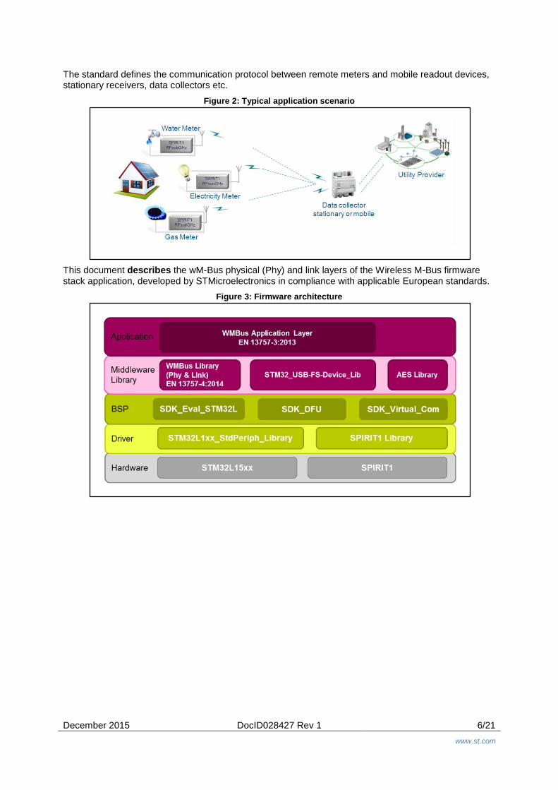
The standard defines the communication protocol between remote meters and mobile readout devices, stationary receivers, data collectors etc.
Figure 2: Typical application scenario
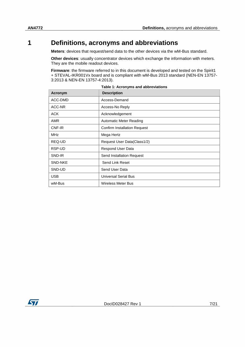
This document describes the wM-Bus physical (Phy) and link layers of the Wireless M-Bus firmware stack application, developed by STMicroelectronics in compliance with applicable European standards.
Figure 3: Firmware architecture
AN4772 Definitions, acronyms and abbreviations
DocID028427 Rev 1 7/21
1 Definitions, acronyms and abbreviations
Meters: devices that request/send data to the other devices via the wM-Bus standard.
Other devices: usually concentrator devices which exchange the information with meters. They are the mobile readout devices.
Firmware: the firmware referred to in this document is developed and tested on the Spirit1 + STEVAL-IKR001Vx board and is compliant with wM-Bus 2013 standard (NEN-EN 13757-3:2013 & NEN-EN 13757-4:2013).
Table 1: Acronyms and abbreviations
Acronym Description
ACC-DMD Access-Demand
ACC-NR Access-No Reply
ACK Acknowledgement
AMR Automatic Meter Reading
CNF-IR Confirm Installation Request
MHz Mega Hertz
REQ-UD Request User Data(Class1/2)
RSP-UD Respond User Data
SND-IR Send Installation Request
SND-NKE Send Link Reset
SND-UD Send User Data
USB Universal Serial Bus
wM-Bus Wireless Meter Bus
Hardware platform AN4772
8/21 DocID028427 Rev 1
2 Hardware platform
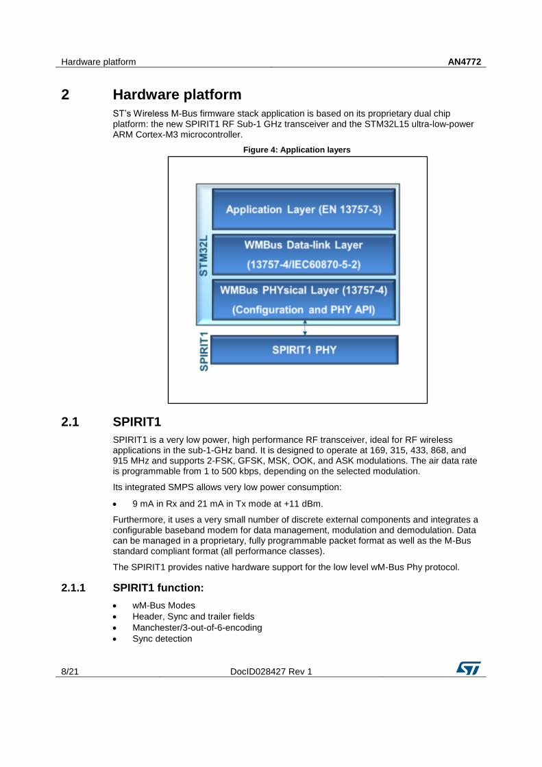
ST’s Wireless M-Bus firmware stack application is based on its proprietary dual chip platform: the new SPIRIT1 RF Sub-1 GHz transceiver and the STM32L15 ultra-low-power ARM Cortex-M3 microcontroller.
Figure 4: Application layers
2.1 SPIRIT1
SPIRIT1 is a very low power, high performance RF transceiver, ideal for RF wireless applications in the sub-1-GHz band. It is designed to operate at 169, 315, 433, 868, and 915 MHz and supports 2-FSK, GFSK, MSK, OOK, and ASK modulations. The air data rate is programmable from 1 to 500 kbps, depending on the selected modulation.
Its integrated SMPS allows very low power consumption:
9 mA in Rx and 21 mA in Tx mode at +11 dBm.
Furthermore, it uses a very small number of discrete external components and integrates a configurable baseband modem for data management, modulation and demodulation. Data can be managed in a proprietary, fully programmable packet format as well as the M-Bus standard compliant format (all performance classes).
The SPIRIT1 provides native hardware support for the low level wM-Bus Phy protocol.
2.1.1 SPIRIT1 function:
wM-Bus Modes
Header, Sync and trailer fields
Manchester/3-out-of-6-encoding
Sync detection
AN4772 Hardware platform
DocID028427 Rev 1 9/21
2.2 ST’s ultra-low power EnergyLite™ MCU family
Gas, water and heat meters with wM-Bus technologies are usually battery powered devices that need to be highly efficient to preserve battery life.
The 8-bit (STM8L) and 32-bit (STM32L) EnergyLite™ family of MCUs combines high performance and ultra-low power, offering specific features for ultra-low power applications such as advanced ultra-low power modes and optimized dynamic run consumption, as well as special safety features.
The ultra-low-power EnergyLite platform, based on STMicroelectronics’ 130 nm ultra-low-leakage process technology, provides a common technology, design and peripheral framework across the product range.
The ARM® Cortex™-M3-based STM32 L1 series extends the ultra-low power concept without compromising performance, offering a wide assortment of features, memory sizes and package pin quantities. The range covers 32 to 384 Kbytes Flash memory (with up to 48 Kbytes of RAM and 12 Kbytes of true embedded EEPROM) and 48 to 144 pins.
This innovative architecture, with voltage scaling and an ultra-low-power MSI oscillator, gives your design more performance for a very low power budget. The generous suite of embedded peripherals, including USB, LCD interface, OpAmp, comparator, ADC with fast on/off mode, DAC, capacitive touch and AES renders the STM32 L1 series an expandable platform able to fit all your requirements.
2.2.1 STM32L function:
wM-Bus application layer
wireless M-Bus application layer partially implementing EN13757-3.
wM-Bus link layer
MAC packet and CRC handling
encryption/ decryption initiate/read.
wM-Bus Phy
init Phy for wM-Bus
interrupt services
Wireless M-Bus protocol overview AN4772
10/21 DocID028427 Rev 1
3 Wireless M-Bus protocol overview
Some of the salient features of the Wireless M-Bus standard are:
support for unidirectional and bidirectional communication between meters and other devices
support for different of communication modes (S, T, R, N (Except N2g), C and F), depending upon the requirement of the application
support for AES-128 encryption for data security
operates both in the license-free ISM and SRD frequency bands at 169, 315, 433, 868, and 915 MHz
provision for indicating faults and alarms.
More details can be found in the EN 13757-4 standard.
For the physical layer, the EN 13757-4 standard also specifies various performance classes depending on the maximum power to be transmitted and lowest receiver sensitivity that the meter provides.
The data link layer of the EN 13757-4 standard supports two different frame formats: A and B. In a standard Wireless M-Bus received frame, the data link layer immediately follows the preamble chip sequence, carrying link layer data plus optional application layer payload information. For C, F and modes, the frame format can be determined from the pattern of the preamble chip sequence. The Wireless M-Bus standard allows for the encryption of the payload data using optimized encryption modes like AES 128 CBC.
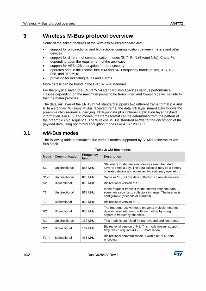
3.1 wM-Bus modes
The following table summarizes the various modes supported by STMicroelectronics wM-Bus stack.
Table 2: wM-Bus modes
Mode Communication Frequency band
Description
S1 Unidirectional 868 MHz Stationary mode: metering devices send their data several times a day. The data collector may be a battery operated device and optimized for stationary operation.
S1-m Unidirectional 868 MHz Same as S1, but the data collector is a mobile receiver.
S2 Bidirectional 868 MHz Bidirectional version of S1.
T1 Unidirectional 868 MHz In the frequent transmit mode, meters send the data every few seconds to collectors in range. The interval is configurable (seconds or minutes).
T2 Bidirectional 868 MHz Bidirectional version of T1.
R2 Bidirectional 868 MHz The frequent receive mode prevents multiple metering devices from interfering with each other by using separate frequency channels.
N1 Unidirectional 169 MHz This mode is optimized for narrowband and long range
N2 Bidirectional 169 MHz Bidirectional version of N1. This mode doesn't support N2g, which requires 4-GFSK modulation.
F2-m Bidirectional 433 MHz Bidirectional communication. It works on NRZ data encoding.
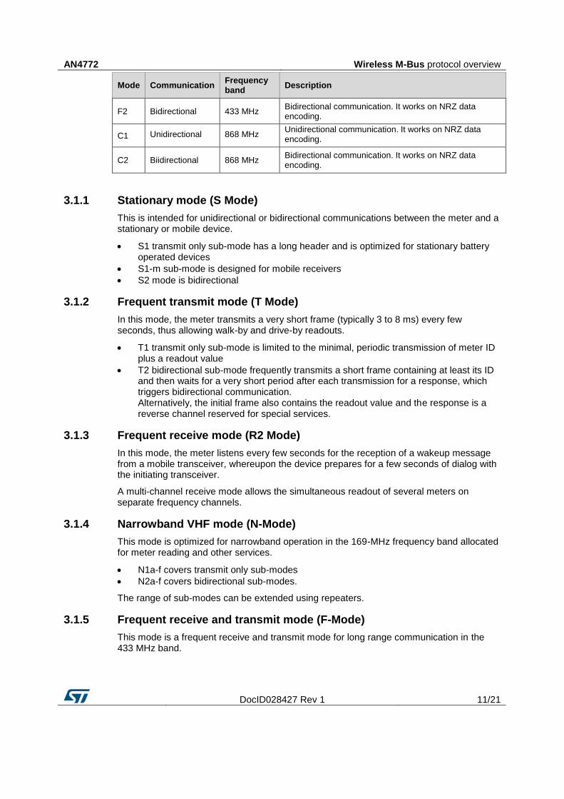
AN4772 Wireless M-Bus protocol overview
DocID028427 Rev 1 11/21
Mode Communication Frequency band
Description
F2 Bidirectional 433 MHz Bidirectional communication. It works on NRZ data encoding.
C1 Unidirectional 868 MHz Unidirectional communication. It works on NRZ data encoding.
C2 Biidirectional 868 MHz Bidirectional communication. It works on NRZ data encoding.
3.1.1 Stationary mode (S Mode)
This is intended for unidirectional or bidirectional communications between the meter and a stationary or mobile device.
S1 transmit only sub-mode has a long header and is optimized for stationary battery operated devices
S1-m sub-mode is designed for mobile receivers
S2 mode is bidirectional
3.1.2 Frequent transmit mode (T Mode)
In this mode, the meter transmits a very short frame (typically 3 to 8 ms) every few seconds, thus allowing walk-by and drive-by readouts.
T1 transmit only sub-mode is limited to the minimal, periodic transmission of meter ID plus a readout value
T2 bidirectional sub-mode frequently transmits a short frame containing at least its ID and then waits for a very short period after each transmission for a response, which triggers bidirectional communication. Alternatively, the initial frame also contains the readout value and the response is a reverse channel reserved for special services.
3.1.3 Frequent receive mode (R2 Mode)
In this mode, the meter listens every few seconds for the reception of a wakeup message from a mobile transceiver, whereupon the device prepares for a few seconds of dialog with the initiating transceiver.
A multi-channel receive mode allows the simultaneous readout of several meters on separate frequency channels.
3.1.4 Narrowband VHF mode (N-Mode)
This mode is optimized for narrowband operation in the 169-MHz frequency band allocated for meter reading and other services.
N1a-f covers transmit only sub-modes
N2a-f covers bidirectional sub-modes.
The range of sub-modes can be extended using repeaters.
3.1.5 Frequent receive and transmit mode (F-Mode)
This mode is a frequent receive and transmit mode for long range communication in the 433 MHz band.
Wireless M-Bus protocol overview AN4772
12/21 DocID028427 Rev 1
F2-m is the bidirectional sub-mode where the meter listens every few seconds for a wake up signal from a stationary or mobile transceiver, upon which the device prepares for a few seconds of dialog with the initiating transceiver.
F2 is the bidirectional sub-mode where the device transmits a frame and waits a short period for a response, which triggers bidirectional communication.
3.1.6 Compact Mode (C-Mode)
This compact Mode operates in the 868 MHz Band. It is similar to the T-Mode, but sends more info with the same energy. It functions in Unidirectional/Bidirectional mode. All communication from the Meter to Other devices is in the form of FSK Modulated data and all communication from Other Device to Meter takes place as GFSK Modulated data. All communication is NRZ encoded.
C1 Mode: Unidirectional Mode
C2 Mode: Bidirectional Mode
AN4772 Wireless M-Bus physical layer
DocID028427 Rev 1 13/21
4 Wireless M-Bus physical layer
The physical structure of the frame includes the preamble (header plus synchronization fields), payload and postamble, as per the figure below.
Figure 5: Wireless M-Bus physical structure.
4.1 Frame structure
4.1.1 Preamble
The preamble consists of the header plus synchronous patterns.
The synchronization word required by EN-13757-4 is 18 bits for S and R modes, 10 bits for T mode, 16 bits for N mode etc. The synchronization word is always preceded by the preamble sequence.
4.1.2 Payload
The block structure of the payload field storing the data to be transmitted is configured in the firmware.
4.1.3 Postamble (trailer)
The number of ‘01’ sequences is added to the postamble at the end of packet as per the wM-Bus standard.
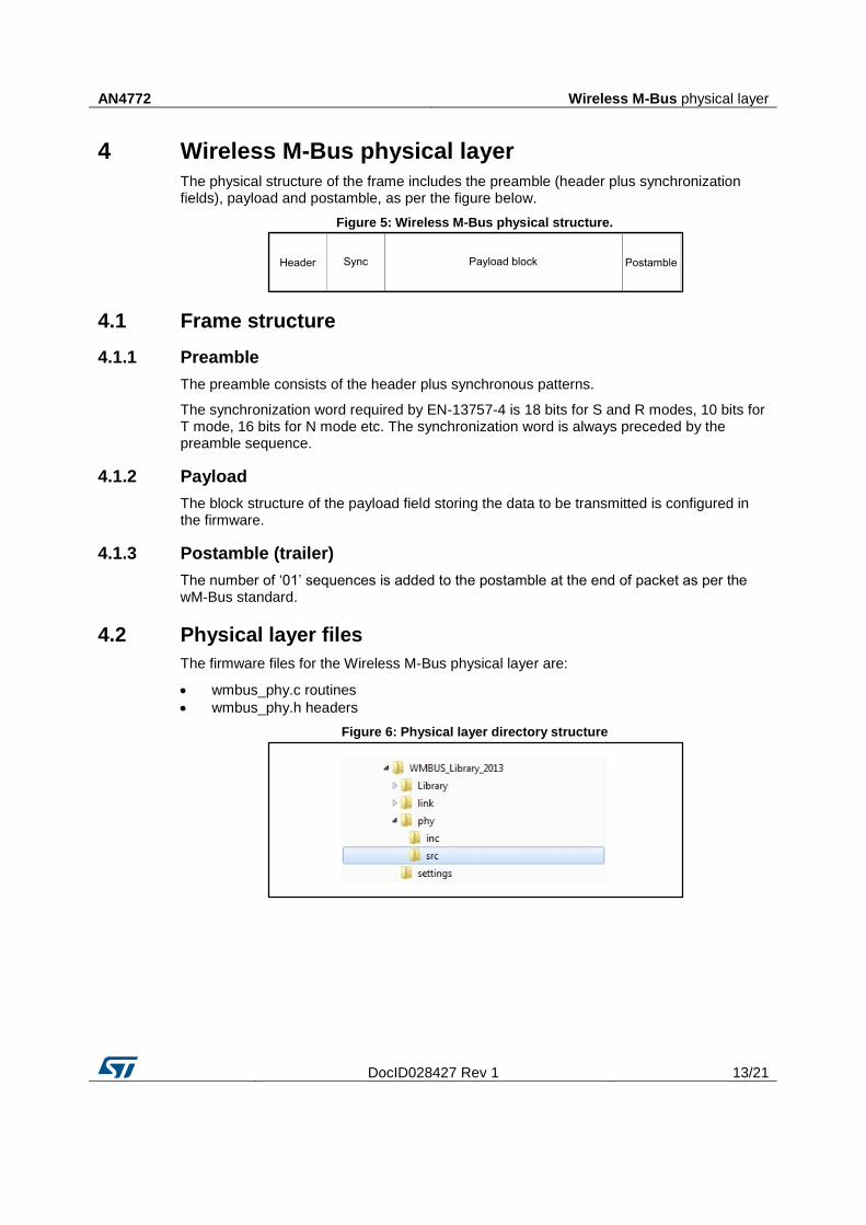
4.2 Physical layer files
The firmware files for the Wireless M-Bus physical layer are:
wmbus_phy.c routines
wmbus_phy.h headers
Figure 6: Physical layer directory structure
Wireless M-Bus link layer AN4772
14/21 DocID028427 Rev 1
5 Wireless M-Bus link layer
The wM-Bus link layer is compliant with EN13757-4:2013 to interface the physical layer (Phy) and the application layer (AL).
5.1 Data link layer functions
The data link layer
provides services to transfer data between the physical and application layers
generates outgoing CRC and verifies CRCs for incoming messages
provides wM-Bus addressing
acknowledges transfers for bidirectional communication modes
wM-Bus frame formation and verification of incoming frames
5.2 Link layer specification
The Wireless M-Bus standard supports two different, A and B, frame formats.
In both formats:
the first block has a fixed length of 10 bytes and includes the frame length (L-field), the control information (C-field) and the sender address (link layer address).
the second block starts with the CI-field which declares the data structure.
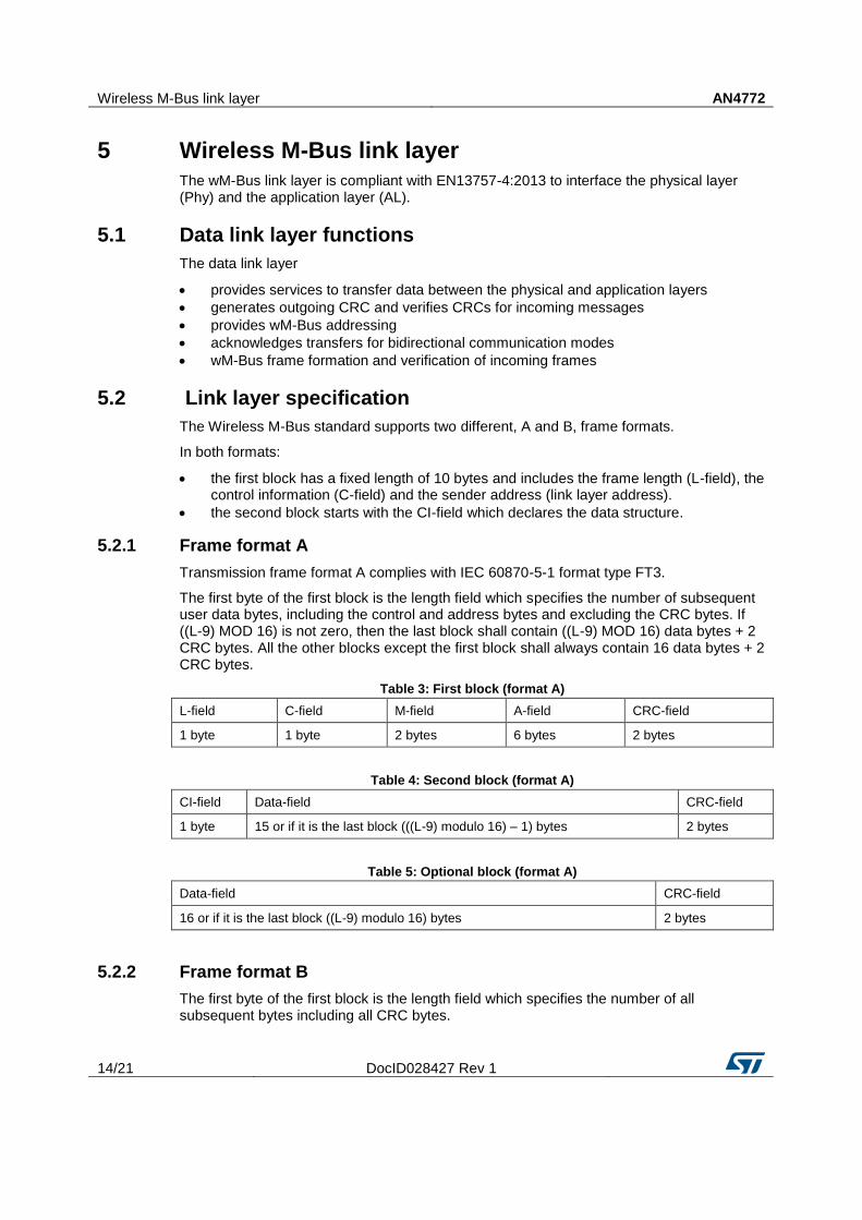
5.2.1 Frame format A
Transmission frame format A complies with IEC 60870-5-1 format type FT3.
The first byte of the first block is the length field which specifies the number of subsequent user data bytes, including the control and address bytes and excluding the CRC bytes. If ((L-9) MOD 16) is not zero, then the last block shall contain ((L-9) MOD 16) data bytes + 2 CRC bytes. All the other blocks except the first block shall always contain 16 data bytes + 2 CRC bytes.
Table 3: First block (format A)
L-field C-field M-field A-field CRC-field
1 byte 1 byte 2 bytes 6 bytes 2 bytes
Table 4: Second block (format A)
CI-field Data-field CRC-field
1 byte 15 or if it is the last block (((L-9) modulo 16) – 1) bytes 2 bytes
Table 5: Optional block (format A)
Data-field CRC-field
16 or if it is the last block ((L-9) modulo 16) bytes 2 bytes
5.2.2 Frame format B
The first byte of the first block is the length field which specifies the number of all subsequent bytes including all CRC bytes.
AN4772 Wireless M-Bus link layer
DocID028427 Rev 1 15/21
Table 6: First block (format B)
L-field C-field M-field A-field
1 byte 1 byte 2 bytes 6 bytes
Table 7: Second block (format B)
CI-field Data-field CRC-field
1 byte 115 or if it is the last block (L-12) bytes 2 bytes
Table 8: Optional block (format B)
Data-field CRC-field
(L-129) bytes 2 bytes
5.2.3 The L-field
The L-field is the first byte of the first block.
frame format A: consists of subsequent user data, control and address bytes, excluding CRC.
frame format B: includes all subsequent bytes including CRC.
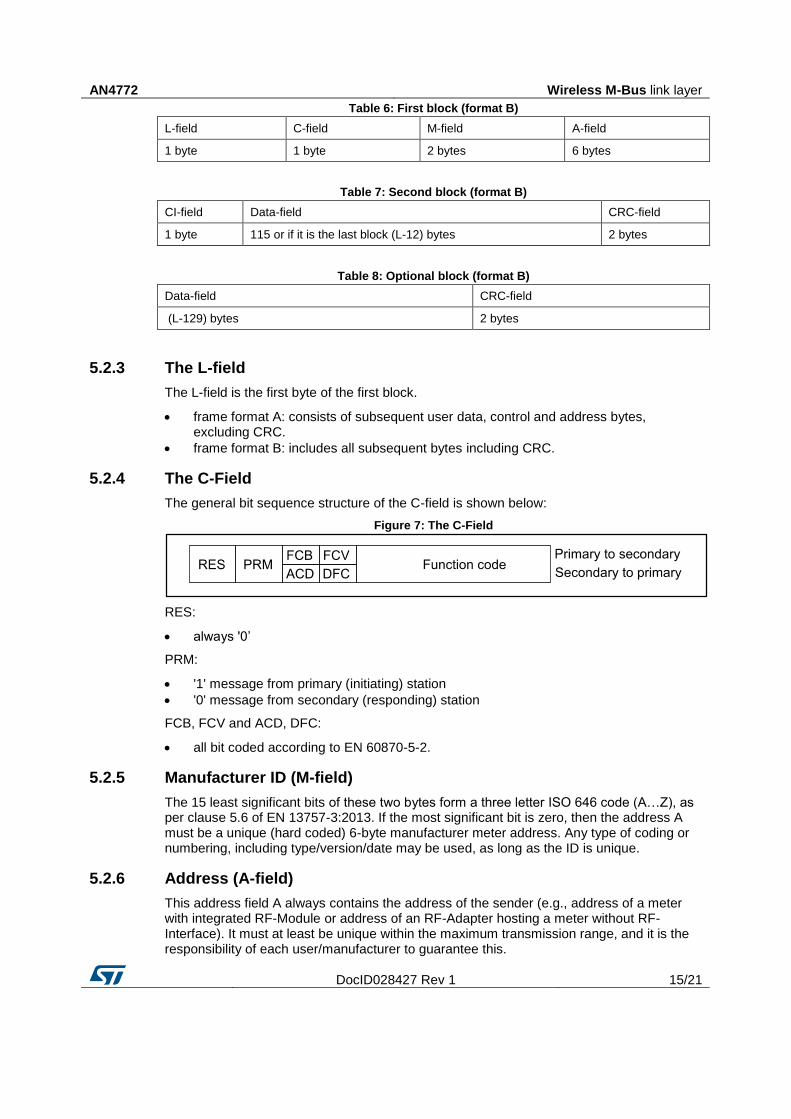
5.2.4 The C-Field
The general bit sequence structure of the C-field is shown below:
Figure 7: The C-Field
RES:
always '0’
PRM:
'1' message from primary (initiating) station
'0' message from secondary (responding) station
FCB, FCV and ACD, DFC:
all bit coded according to EN 60870-5-2.
5.2.5 Manufacturer ID (M-field)
The 15 least significant bits of these two bytes form a three letter ISO 646 code (A…Z), as per clause 5.6 of EN 13757-3:2013. If the most significant bit is zero, then the address A must be a unique (hard coded) 6-byte manufacturer meter address. Any type of coding or numbering, including type/version/date may be used, as long as the ID is unique.
5.2.6 Address (A-field)
This address field A always contains the address of the sender (e.g., address of a meter with integrated RF-Module or address of an RF-Adapter hosting a meter without RF-Interface). It must at least be unique within the maximum transmission range, and it is the responsibility of each user/manufacturer to guarantee this.
Wireless M-Bus link layer AN4772
16/21 DocID028427 Rev 1
If this protocol is used together with the Transport Layer or the Application Layer of EN 13757-3, then the A-field address structure is a concatenation of the 'Identification number', 'Version number' and 'Device type information'.
5.2.7 CI-field
The CI-field is the application header and specifies the type of data in the application data payload. While EN13757-4:2011 specifies a limited number of values, the Link Service Primitives allow any value to be used.
5.2.8 Data field
The user data to be transmitted is stored in this field.
5.2.9 Cyclic redundancy check (CRC-field)
The CRC calculation is based on the information from the previous block according to FT3 of EN 60870-5-1.
The formula is:
The CRC polynomial is: x16 + x13 + x12 + x11 + x10 + x8 + x6 + x5 + x2 + 1
The initial value is 0; the final CRC is complemented.
5.3 Link layer firmware implementation
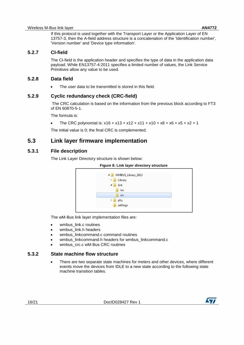
5.3.1 File description
The Link Layer Directory structure is shown below:
Figure 8: Link layer directory structure
The wM-Bus link layer implementation files are:
wmbus_link.c routines
wmbus_link.h headers
wmbus_linkcommand.c command routines
wmbus_linkcommand.h headers for wmbus_linkcommand.c
wmbus_crc.c wM-Bus CRC routines
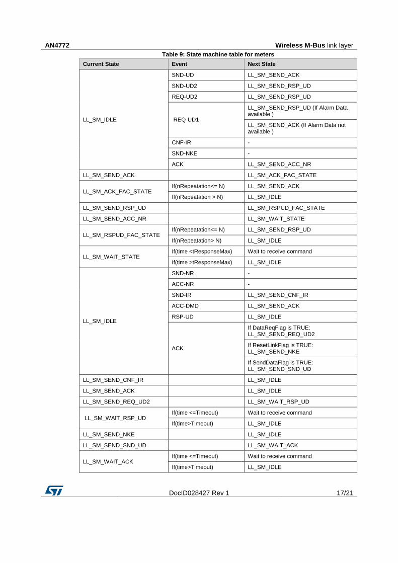
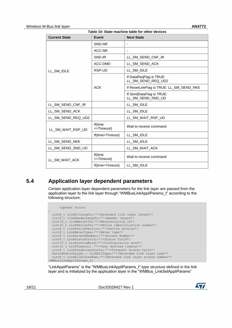
5.3.2 State machine flow structure
There are two separate state machines for meters and other devices, where different events move the devices from IDLE to a new state according to the following state machine transition tables.
AN4772 Wireless M-Bus link layer
DocID028427 Rev 1 17/21
Table 9: State machine table for meters
Current State Event Next State
LL_SM_IDLE
SND-UD LL_SM_SEND_ACK
SND-UD2 LL_SM_SEND_RSP_UD
REQ-UD2 LL_SM_SEND_RSP_UD
REQ-UD1
LL_SM_SEND_RSP_UD (If Alarm Data available )
LL_SM_SEND_ACK (If Alarm Data not available )
CNF-IR -
SND-NKE -
ACK LL_SM_SEND_ACC_NR
LL_SM_SEND_ACK
LL_SM_ACK_FAC_STATE
LL_SM_ACK_FAC_STATE If(nRepeatation<= N) LL_SM_SEND_ACK
If(nRepeatation > N) LL_SM_IDLE
LL_SM_SEND_RSP_UD
LL_SM_RSPUD_FAC_STATE
LL_SM_SEND_ACC_NR
LL_SM_WAIT_STATE
LL_SM_RSPUD_FAC_STATE If(nRepeatation<= N) LL_SM_SEND_RSP_UD
If(nRepeatation> N) LL_SM_IDLE
LL_SM_WAIT_STATE If(time <tResponseMax) Wait to receive command
If(time >tResponseMax) LL_SM_IDLE
LL_SM_IDLE
SND-NR -
ACC-NR -
SND-IR LL_SM_SEND_CNF_IR
ACC-DMD LL_SM_SEND_ACK
RSP-UD LL_SM_IDLE
ACK
If DataReqFlag is TRUE: LL_SM_SEND_REQ_UD2
If ResetLinkFlag is TRUE: LL_SM_SEND_NKE
If SendDataFlag is TRUE: LL_SM_SEND_SND_UD
LL_SM_SEND_CNF_IR
LL_SM_IDLE
LL_SM_SEND_ACK
LL_SM_IDLE
LL_SM_SEND_REQ_UD2
LL_SM_WAIT_RSP_UD
LL_SM_WAIT_RSP_UD If(time <=Timeout) Wait to receive command
If(time>Timeout) LL_SM_IDLE
LL_SM_SEND_NKE
LL_SM_IDLE
LL_SM_SEND_SND_UD
LL_SM_WAIT_ACK
LL_SM_WAIT_ACK If(time <=Timeout) Wait to receive command
If(time>Timeout) LL_SM_IDLE
Wireless M-Bus link layer AN4772
18/21 DocID028427 Rev 1
Table 10: State machine table for other devices
Current State Event Next State
LL_SM_IDLE
SND-NR -
ACC-NR -
SND-IR LL_SM_SEND_CNF_IR
ACC-DMD LL_SM_SEND_ACK
RSP-UD LL_SM_IDLE
ACK
If DataReqFlag is TRUE: LL_SM_SEND_REQ_UD2
If ResetLinkFlag is TRUE: LL_SM_SEND_NKE
If SendDataFlag is TRUE: LL_SM_SEND_SND_UD
LL_SM_SEND_CNF_IR
LL_SM_IDLE
LL_SM_SEND_ACK
LL_SM_IDLE
LL_SM_SEND_REQ_UD2
LL_SM_WAIT_RSP_UD
LL_SM_WAIT_RSP_UD
If(time <=Timeout)
Wait to receive command
If(time>Timeout) LL_SM_IDLE
LL_SM_SEND_NKE
LL_SM_IDLE
LL_SM_SEND_SND_UD
LL_SM_WAIT_ACK
LL_SM_WAIT_ACK
If(time <=Timeout)
Wait to receive command
If(time>Timeout) LL_SM_IDLE
5.4 Application layer dependent parameters
Certain application layer dependent parameters for the link layer are passed from the application layer to the link layer through “WMBusLinkAppliParams_t” according to the following structure:
typedef struct
{
uint8_t LinkEllLength;/*!<Extended link layer length*/
uint8_t LinkHeaderLength;/*!<Header length*/
uint16_t LinkManufrID;/*!<Manufacturing id*/
uint32_t LinkDeviceID;/*!<Device identification number*/
uint8_t LinkDeviceVersion;/*!<Device version*/
uint8_t LinkMeterType;/*!<Meter type*/
uint8_t LinkAccessNumber;/*!<Access Number*/
uint8_t LinkStatusField;/*!<Status field*/
uint16_t LinkConfigWord;/*!<Configuration word*/
uint32_t LinkTimeout; /*!<User defined timeout*/
uint8_t LinkFreqAccessCycle;/*!<Frequent Access Cycle*/
ExtendedLinkLayer_t LinkEllType;/*!<Extended link layer type*/
uint8_t LinkEllAccessNum;/*!<Extended link layer access number*/
}WMBusLinkAppliParams_t;
“LinkAppliParams” is the “WMBusLinkAppliParams_t”-type structure defined in the link layer and is initialized by the application layer in the “WMBus_LinkSetAppliParams”
AN4772 Wireless M-Bus link layer
DocID028427 Rev 1 19/21
function via pointer. The user then calls the “WMBus_LinkSetAppliParams” function from the application layer to set the user-dependent parameters for the link layer.
Revision history AN4772
20/21 DocID028427 Rev 1
6 Revision history Table 11: Document revision history
Date Version Changes
02-Dec-2015 1 Initial release.
AN4772
DocID028427 Rev 1 21/21
IMPORTANT NOTICE – PLEASE READ CAREFULLY
STMicroelectronics NV and its subsidiaries (“ST”) reserve the right to make changes, corrections, enhancements, modifications , and improvements to ST products and/or to this document at any time without notice. Purchasers should obtain the latest relevant information on ST products before placing orders. ST products are sold pursuant to ST’s terms and conditions of sale in place at the time of order acknowledgement.
Purchasers are solely responsible for the choice, selection, and use of ST products and ST assumes no liability for application assistance or the design of Purchasers’ products.
No license, express or implied, to any intellectual property right is granted by ST herein.
Resale of ST products with provisions different from the information set forth herein shall void any warranty granted by ST for such product.
ST and the ST logo are trademarks of ST. All other product or service names are the property of their respective owners.
Information in this document supersedes and replaces information previously supplied in any prior versions of this document.
© 2015 STMicroelectronics – All rights reserved


![Soldadoras - pdwatersystems.com · soldadoras wm 140 wm 180 wm 250 características modelo wm 140 wm 180 wm 250 voltaje [ v ] 110 110 / 220 110/220 fases 1 1 1 diametro de electrodo](https://img.pdfslide.net/doc/110x75/5ba485f909d3f2a9218d9d00/soldadoras-soldadoras-wm-140-wm-180-wm-250-caracteristicas-modelo-wm-140.jpg)


![[ZigBee 嵌入式系統] ZigBee 應用實作 - 使用 TI Z-Stack Firmware](https://img.pdfslide.net/doc/110x75/55c60573bb61ebd7258b473c/zigbee-zigbee-ti-z-stack-firmware.jpg)


![[ZigBee 嵌入式系統] ZigBee Architecture 與 TI Z-Stack Firmware](https://img.pdfslide.net/doc/110x75/55c60532bb61ebdf258b46fc/zigbee-zigbee-architecture-ti-z-stack-firmware.jpg)
