Embed Size (px)
Citation preview
©2012 DJI Innovations. All Rights Reserved. 1
WooKong HELI
User Manual V 1.8
www.dji-innovations.com
©2012 DJI Innovations. All Rights Reserved. 2 |
Disclaimer DJI Innovations assumes no liability for damage(s) or injured incurred directly or indirectly from the use of this product.
DJI WooKong is registered trademark of DJI Innovations. Names of product, brand, etc., appearing in this manual are trademarks or
registered trademarks of their respective owner companies. This product and manual are copyrighted by DJI Innovations with all rights
reserved. No part of this product or manual shall be reproduced in any form without the prior written consent or authorization of DJI
Innovations. No patent liability is assumed with respect to the use of the product or information contained herein.
Reader’s Guide for This Manual Please strictly follow these steps to mount and connect WooKong for Heli (WKH) system on your helicopter, as well as to install the
WKH Assistant Software on your computer. Please pay attention at Lite for the difference between WKH and WKH Lite.
Icons seen in this document:
FORBIDDEN
Please refer to the page(s) mentioned TX
R/C Transmitter configuration required
WKH Assistant
configuration required
CAUTION
Assembly&
Mounting Tips General Tips Correct/ Wrong
Contents DJI WKH Introduction ........................................ 3
Package Contents .............................................. 4
Mounting and Connection ................................. 5
A1 Before you Begin ........................................... 5
A2 Mount the devices on your helicopter ............ 5
A3 Connections................................................... 7
A4 WKH Assistant Software Basic Operation ..... 9
Flight & Configuration Procedure Brief ......... 10
Configuration Procedure ................................. 11
B1 GPS & IMU Mounting .................................. 11
B2 Control Mode Switch ................................... 12
B3 Flybarless .................................................... 13
B4 Swashplate .................................................. 14
B5 Pitch and Throttle Curve Setup.................... 14
B6 Tail Gyro ...................................................... 15
B7 Engine Governor ......................................... 16
B8 R/C Transmitter Calibration ......................... 17
B9 System Check ............................................. 18
B10 Autopilot ...................................................... 19
Flight ................................................................. 20
C1 Digital Compass Calibration ........................ 20
C2 MANUAL MODE Test Flight ........................ 21
C3 Fail-Safe ...................................................... 22
C4 Autopilot Test Fight...................................... 23
Maintains .......................................................... 23
Firmware Upgrade ................................................ 25
Product Info ........................................................... 25
Appendix ........................................................... 26
WKH LED Indicator Description ............................ 26
WKH Lite LED Indicator Description ..................... 26
Product Specifications ........................................... 27
©2012 DJI Innovations. All Rights Reserved. 3 |
DJI WKH Introduction WKH is the flight system designed for serious scale helicopter enthusiasts providing GPS for self-leveling, position hold, speed control
and built-in tail gyro which completely takes the stress out of flying RC helicopters for both professional and hobby applications. WKH
can be installed in a variety of models, from small electric helicopters to large gasoline and turbine helicopters. WKH Lite is the no GPS
and LED version of WKH.
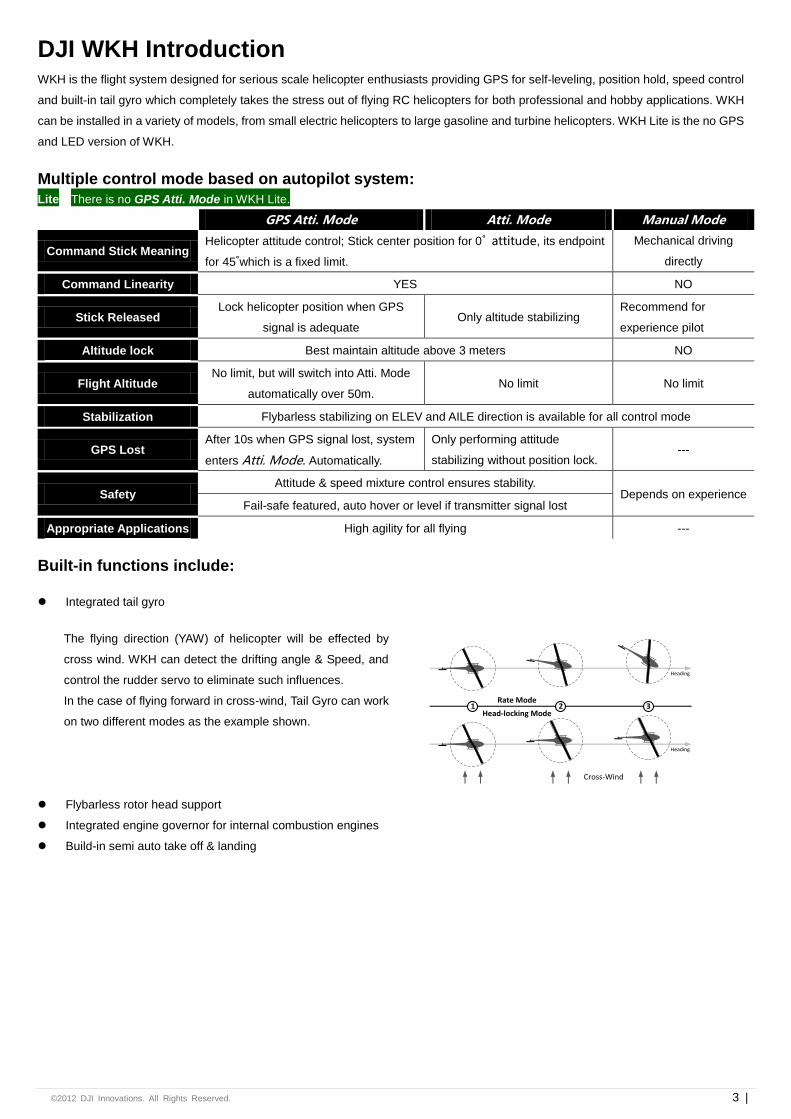
Multiple control mode based on autopilot system:
Lite There is no GPS Atti. Mode in WKH Lite.
GPS Atti. Mode Atti. Mode Manual Mode
Command Stick Meaning Helicopter attitude control; Stick center position for 0˚ attitude, its endpoint
for 45˚which is a fixed limit.
Mechanical driving
directly
Command Linearity YES NO
Stick Released Lock helicopter position when GPS
signal is adequate Only altitude stabilizing
Recommend for
experience pilot
Altitude lock Best maintain altitude above 3 meters NO
Flight Altitude No limit, but will switch into Atti. Mode
automatically over 50m. No limit No limit
Stabilization Flybarless stabilizing on ELEV and AILE direction is available for all control mode
GPS Lost After 10s when GPS signal lost, system
enters Atti. Mode. Automatically.
Only performing attitude
stabilizing without position lock. ---
Safety Attitude & speed mixture control ensures stability.
Depends on experience Fail-safe featured, auto hover or level if transmitter signal lost
Appropriate Applications High agility for all flying ---
Built-in functions include:
Integrated tail gyro
The flying direction (YAW) of helicopter will be effected by
cross wind. WKH can detect the drifting angle & Speed, and
control the rudder servo to eliminate such influences.
In the case of flying forward in cross-wind, Tail Gyro can work
on two different modes as the example shown.
Heading
Heading
Head-locking Mode
Rate Mode
Cross-Wind
1 2 3
Flybarless rotor head support
Integrated engine governor for internal combustion engines
Build-in semi auto take off & landing
©2012 DJI Innovations. All Rights Reserved. 4 |
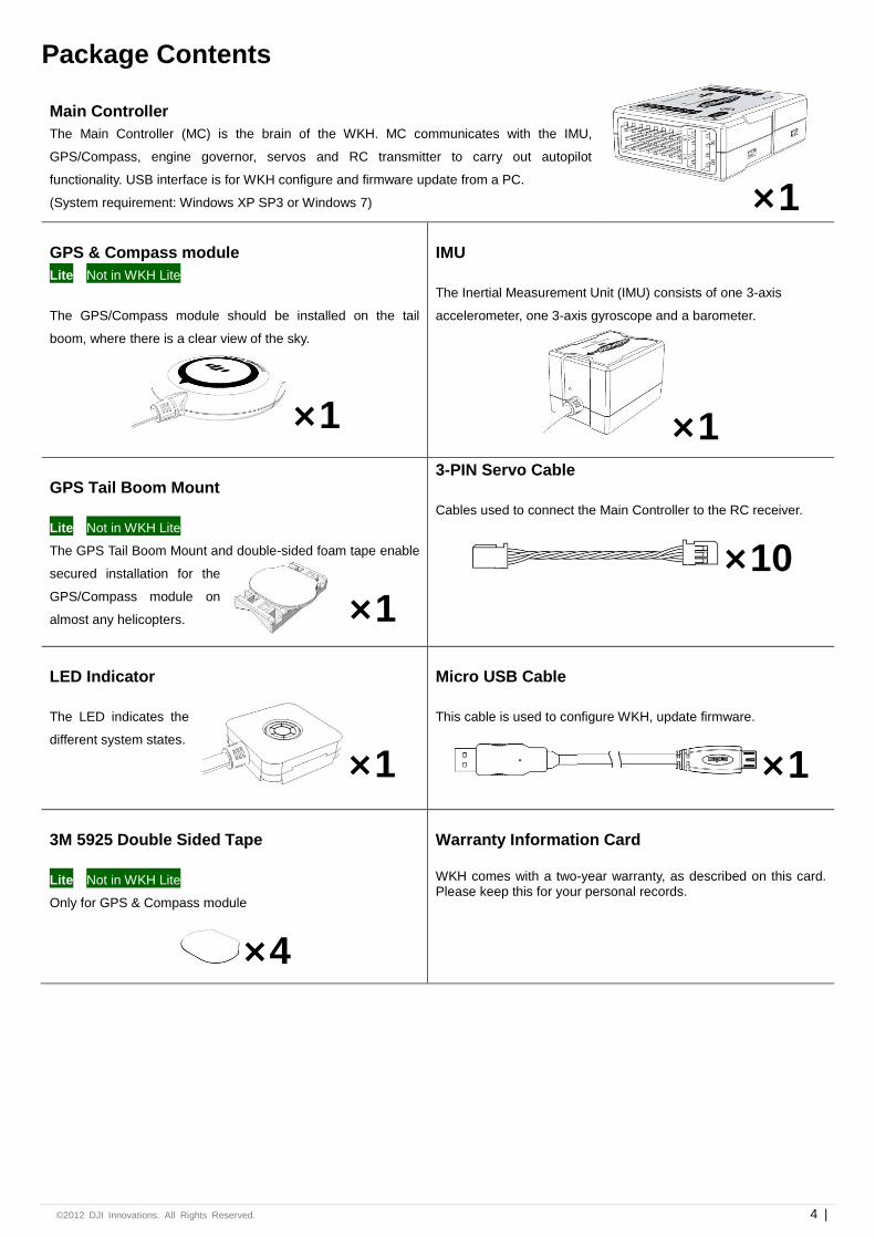
Package Contents
Main Controller
The Main Controller (MC) is the brain of the WKH. MC communicates with the IMU,
GPS/Compass, engine governor, servos and RC transmitter to carry out autopilot
functionality. USB interface is for WKH configure and firmware update from a PC.
(System requirement: Windows XP SP3 or Windows 7)
GPS & Compass module
Lite Not in WKH Lite
The GPS/Compass module should be installed on the tail
boom, where there is a clear view of the sky.
×1
IMU
The Inertial Measurement Unit (IMU) consists of one 3-axis
accelerometer, one 3-axis gyroscope and a barometer.
×1
GPS Tail Boom Mount
Lite Not in WKH Lite
The GPS Tail Boom Mount and double-sided foam tape enable
secured installation for the
GPS/Compass module on
almost any helicopters.
3-PIN Servo Cable
Cables used to connect the Main Controller to the RC receiver.
×10
LED Indicator
The LED indicates the
different system states.
Micro USB Cable
This cable is used to configure WKH, update firmware.
×1
3M 5925 Double Sided Tape
Lite Not in WKH Lite
Only for GPS & Compass module
×4
Warranty Information Card
WKH comes with a two-year warranty, as described on this card. Please keep this for your personal records.
×1
×1
×1
©2012 DJI Innovations. All Rights Reserved. 5 |
Mounting and Connection
A1 Before you Begin Fly the helicopter without WKH in open are or large field and make sure that the helicopter works properly without any autopilot
assistance. To do so, you will need external tail gyro. This is a good time to isolate and resolve unwanted vibrations. IT IS IMPORTANT
THAT YOU SHOULD NOT SKIP THIS STEP.
A2 Mount the devices on your helicopter
IMU
Where? The IMU is best positioned near the helicopter’s center of gravity, where
vibration is relatively low.
What orientation? Orient the IMU such that the arrow marked on the above
surface of the IMU faces the sky and points directly forward, backward, left or
right. The sides of the IMU should be precisely parallel to the helicopter body.
DO NOT MOUNT THE IMU UPSIDE-DOWN.
How? Use double-sided foam tape for secured installation.
1 Check the double-sided foam tape or Velcro regularly to ensure that the
IMU is securely positioned.
2 DO NOT cover the ventilation holes, keep them unobstructed.
3 The IMU module is NOT water-proof or oil-proof.
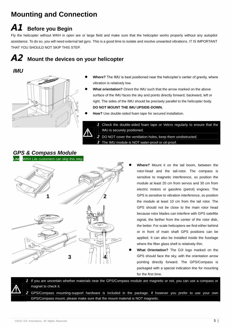
GPS & Compass Module Lite WKH Lite customers can skip this step.
Where? Mount it on the tail boom, between the
rotor-head and the tail-rotor. The compass is
sensitive to magnetic interference, so position the
module at least 20 cm from servos and 30 cm from
electric motors or gasoline (petrol) engines. The
GPS is sensitive to vibration interference, so position
the module at least 10 cm from the tail rotor. The
GPS should not be close to the main rotor head
because rotor blades can interfere with GPS satellite
signal, the farther from the center of the rotor disk,
the better. For scale helicopters we find either behind
or in front of main shaft GPS positions can be
applied. It can also be installed inside the fuselage
where the fiber glass shell is relatively thin.
What Orientation? The DJI logo marked on the
GPS should face the sky, with the orientation arrow
pointing directly forward. The GPS/Compass is
packaged with a special indication line for mounting
for the first time.
1 If you are uncertain whether materials near the GPS/Compass module are magnetic or not, you can use a compass or
magnet to check it.
2 GPS/Compass mounting-support hardware is included in the package. If however you prefer to use your own
GPS/Compass mount, please make sure that the mount material is NOT magnetic.
1 2
3 4
©2012 DJI Innovations. All Rights Reserved. 6 |
Main Controller Where? There is no orientation requirement for the Main Controller. Maintain at least a 20-centimeter-distance between the
Main Controller and the engine or motor. Choose a mounting location where as shorter servo extension wires are needed as
possible. This helps reduce the risks of electronic interference. Please also make sure the USB port is accessible when installing
the Main Controller so as to facilitate software configuration.
After choosing a location to mount the Main Controller, it is recommended that you DO NOT mount the Main Controller until
all wirings and software configurations are completed.
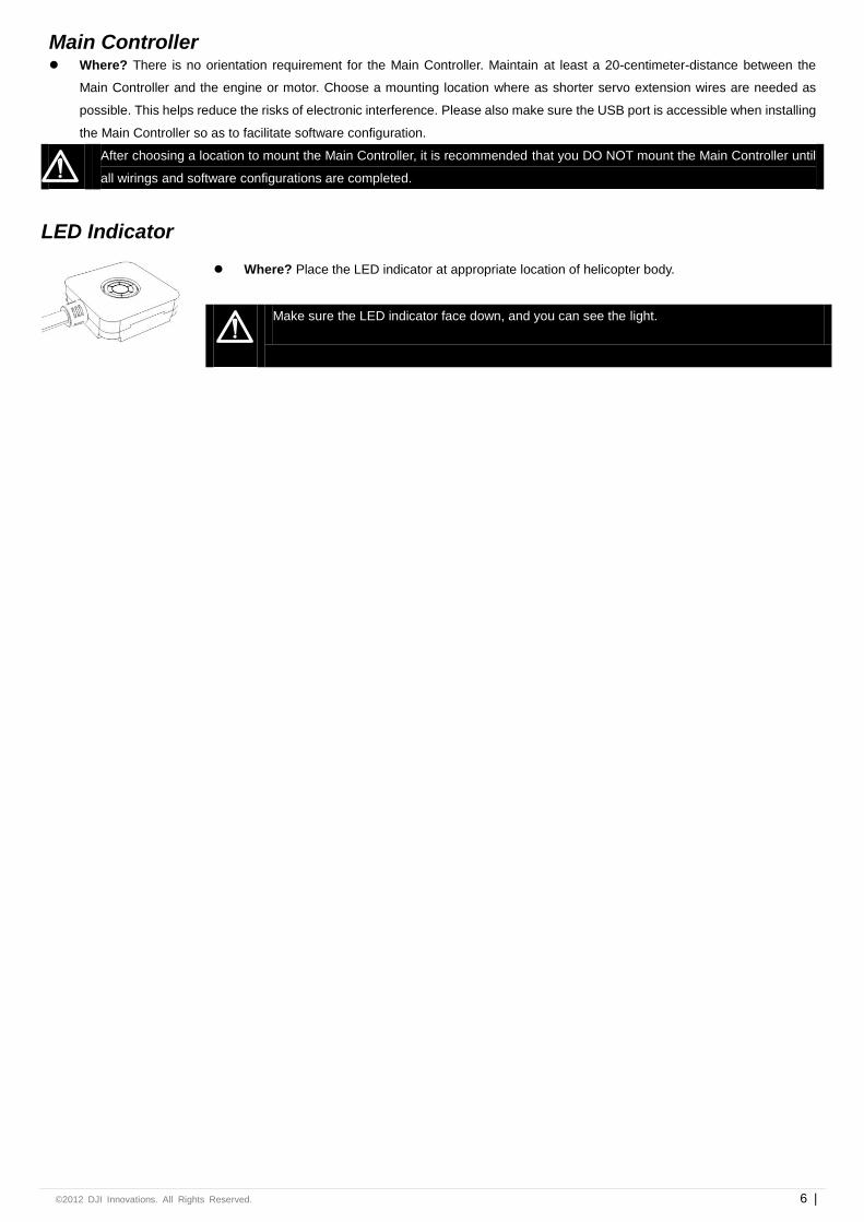
LED Indicator
Where? Place the LED indicator at appropriate location of helicopter body.
Make sure the LED indicator face down, and you can see the light.
©2012 DJI Innovations. All Rights Reserved. 7 |
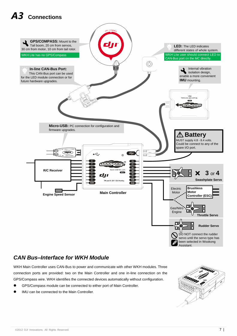
A3 Connections
Rudder Servo
DO NOT connect the rudder
servo until the servo type has
been selected in Wookong
Assistant.
Brushless
Motor
Controller (ESC)
Electric
Motor
Gas/Nitro
EngineThrottle Servo
Swashplate Servo
3 or 4
Battery MUST supply 4.8 - 8.4 volts.
Could be connect to any of the
spare I/O port.
Micro-USB: PC connection for configuration and
firmware upgrades.
GPS/COMPASS: Mount to the
Tail boom, 20 cm from servos,
30 cm from motor, 10 cm from tail rotor.
Internal vibration
isolation design,
enable a more convenient
IMU mounting.
Main Controller Engine Speed Sensor
R/C Receiver
LED: The LED indicates
different states of whole system.
In-line CAN-Bus Port:
This CAN-Bus port can be used
for the LED module connection or for
future hardware upgrades.
WKH Lite has no GPS/Compass WKH Lite user should connect LED to
CAN-Bus port on the MC directly.
CAN Bus–Interface for WKH Module
WKH Main Controller uses CAN-Bus to power and communicate with other WKH modules. Three
connection ports are provided: two on the Main Controller and one in-line connection on the
GPS/Compass wire. WKH identifies the connected devices automatically without configuration.
GPS/Compass module can be connected to either port of Main Controller.
IMU can be connected to the Main Controller.
©2012 DJI Innovations. All Rights Reserved. 8 |
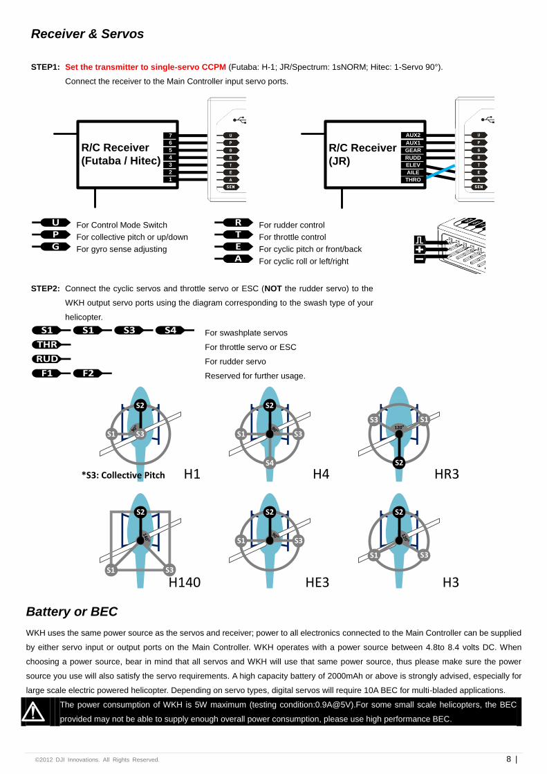
Receiver & Servos
STEP1: Set the transmitter to single-servo CCPM (Futaba: H-1; JR/Spectrum: 1sNORM; Hitec: 1-Servo 90°).
Connect the receiver to the Main Controller input servo ports.
R/C Receiver
(Futaba / Hitec)
1
2
3
4
5
6
7
R/C Receiver
(JR)
AUX2
AUX1
GEAR
RUDD
ELEV
RUDD
THRO
AILE
ELEV
GEAR
AUX1
AUX2
U For Control Mode Switch P For collective pitch or up/down
G For gyro sense adjusting
R For rudder control T For throttle control
E For cyclic pitch or front/back
A For cyclic roll or left/right
STEP2: Connect the cyclic servos and throttle servo or ESC (NOT the rudder servo) to the
WKH output servo ports using the diagram corresponding to the swash type of your
helicopter.
S1 S1 S3 S4 For swashplate servos
THR For throttle servo or ESC
RUD For rudder servo
F1 F2 Reserved for further usage.
S2
S190
o
S3
S4
S2
S1 S390 o
S2
S1 S3
140 o
S2
S1 S390 o
S2
S1 S3
120 o
S2
S1S3120o
HR3
H3H140
H4
HE3
H1*S3: Collective Pitch
Battery or BEC
WKH uses the same power source as the servos and receiver; power to all electronics connected to the Main Controller can be supplied
by either servo input or output ports on the Main Controller. WKH operates with a power source between 4.8to 8.4 volts DC. When
choosing a power source, bear in mind that all servos and WKH will use that same power source, thus please make sure the power
source you use will also satisfy the servo requirements. A high capacity battery of 2000mAh or above is strongly advised, especially for
large scale electric powered helicopter. Depending on servo types, digital servos will require 10A BEC for multi-bladed applications.
The power consumption of WKH is 5W maximum (testing condition:0.9A@5V).For some small scale helicopters, the BEC
provided may not be able to supply enough overall power consumption, please use high performance BEC.
©2012 DJI Innovations. All Rights Reserved. 9 |
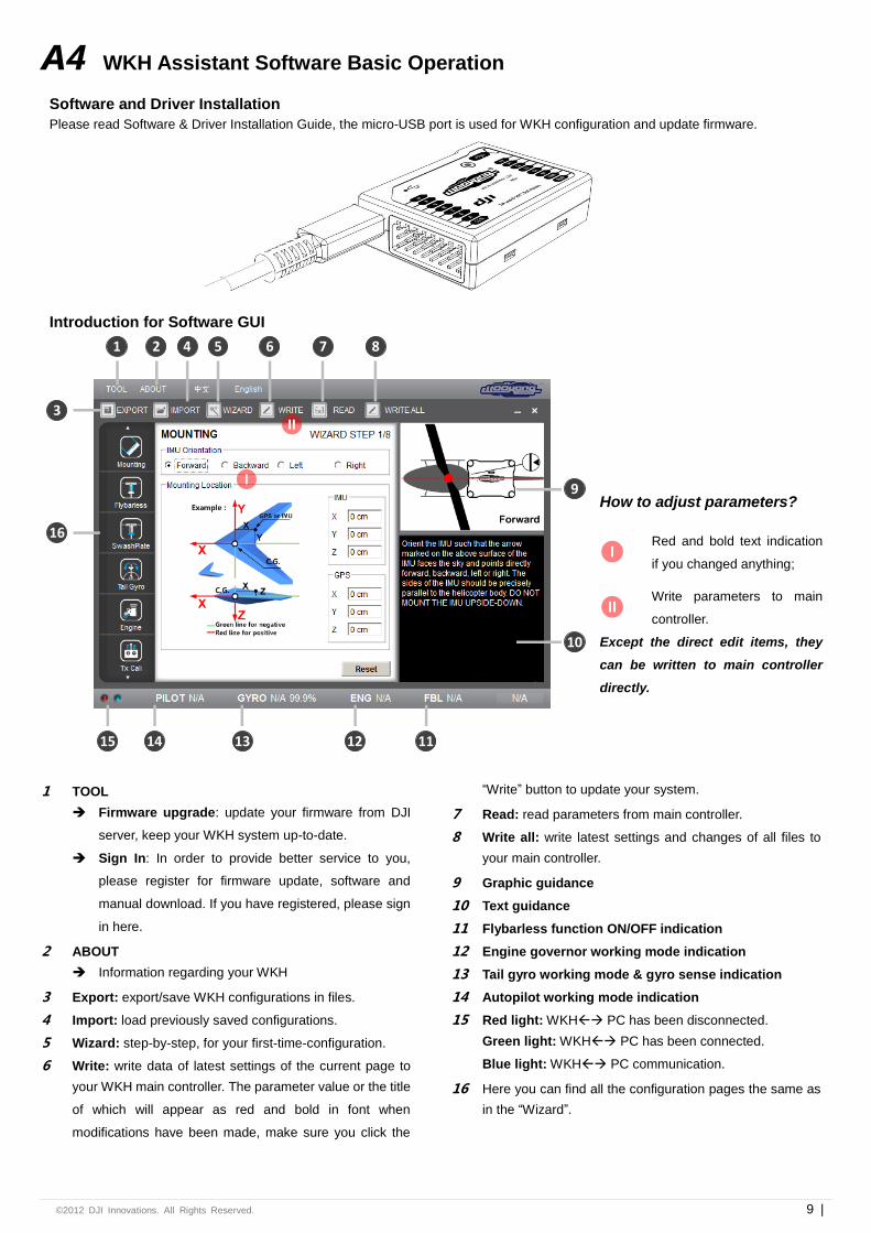
A4 WKH Assistant Software Basic Operation
Software and Driver Installation
Please read Software & Driver Installation Guide, the micro-USB port is used for WKH configuration and update firmware.
Introduction for Software GUI
1 2
3
4
16
15 14 13 12 11
10
6 75 8
9I
II
How to adjust parameters?
I
Red and bold text indication
if you changed anything;
II
Write parameters to main
controller.
Except the direct edit items, they
can be written to main controller
directly.
1 TOOL
Firmware upgrade: update your firmware from DJI
server, keep your WKH system up-to-date.
Sign In: In order to provide better service to you,
please register for firmware update, software and
manual download. If you have registered, please sign
in here.
2 ABOUT
Information regarding your WKH
3 Export: export/save WKH configurations in files.
4 Import: load previously saved configurations.
5 Wizard: step-by-step, for your first-time-configuration.
6 Write: write data of latest settings of the current page to
your WKH main controller. The parameter value or the title
of which will appear as red and bold in font when
modifications have been made, make sure you click the
“Write” button to update your system.
7 Read: read parameters from main controller.
8 Write all: write latest settings and changes of all files to
your main controller.
9 Graphic guidance
10 Text guidance
11 Flybarless function ON/OFF indication
12 Engine governor working mode indication
13 Tail gyro working mode & gyro sense indication
14 Autopilot working mode indication
15 Red light: WKH PC has been disconnected.
Green light: WKH PC has been connected.
Blue light: WKH PC communication.
16 Here you can find all the configuration pages the same as
in the “Wizard”.
©2012 DJI Innovations. All Rights Reserved. 10
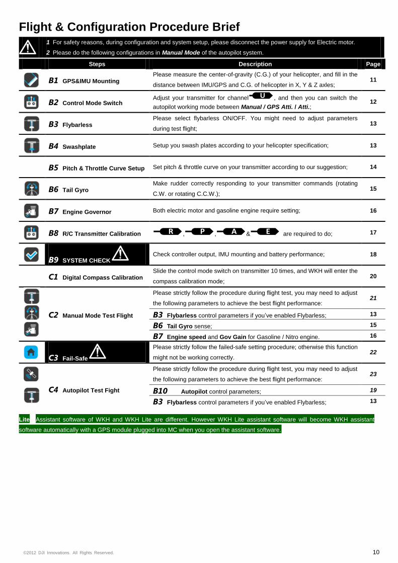
Flight & Configuration Procedure Brief
1 For safety reasons, during configuration and system setup, please disconnect the power supply for Electric motor.
2 Please do the following configurations in Manual Mode of the autopilot system.
Steps Description Page
B1 GPS&IMU Mounting
Please measure the center-of-gravity (C.G.) of your helicopter, and fill in the
distance between IMU/GPS and C.G. of helicopter in X, Y & Z axles; 11
B2 Control Mode Switch
Adjust your transmitter for channel U , and then you can switch the
autopilot working mode between Manual / GPS Atti. / Atti.; 12
B3 Flybarless
Please select flybarless ON/OFF. You might need to adjust parameters
during test flight; 13
B4 Swashplate Setup you swash plates according to your helicopter specification; 13
B5 Pitch & Throttle Curve Setup Set pitch & throttle curve on your transmitter according to our suggestion; 14
B6 Tail Gyro
Make rudder correctly responding to your transmitter commands (rotating
C.W. or rotating C.C.W.); 15
B7 Engine Governor Both electric motor and gasoline engine require setting; 16
B8 R/C Transmitter Calibration R , P , A & E are required to do; 17
B9 SYSTEM CHECK Check controller output, IMU mounting and battery performance; 18
C1 Digital Compass Calibration
Slide the control mode switch on transmitter 10 times, and WKH will enter the
compass calibration mode; 20
C2 Manual Mode Test Flight
Please strictly follow the procedure during flight test, you may need to adjust
the following parameters to achieve the best flight performance: 21
B3 Flybarless control parameters if you’ve enabled Flybarless; 13
B6 Tail Gyro sense; 15
B7 Engine speed and Gov Gain for Gasoline / Nitro engine. 16
C3 Fail-Safe
Please strictly follow the failed-safe setting procedure; otherwise this function
might not be working correctly. 22
C4 Autopilot Test Fight
Please strictly follow the procedure during flight test, you may need to adjust
the following parameters to achieve the best flight performance: 23
B10 Autopilot control parameters; 19
B3 Flybarless control parameters if you’ve enabled Flybarless; 13
Lite Assistant software of WKH and WKH Lite are different. However WKH Lite assistant software will become WKH assistant
software automatically with a GPS module plugged into MC when you open the assistant software.
©2012 DJI Innovations. All Rights Reserved. 11 |
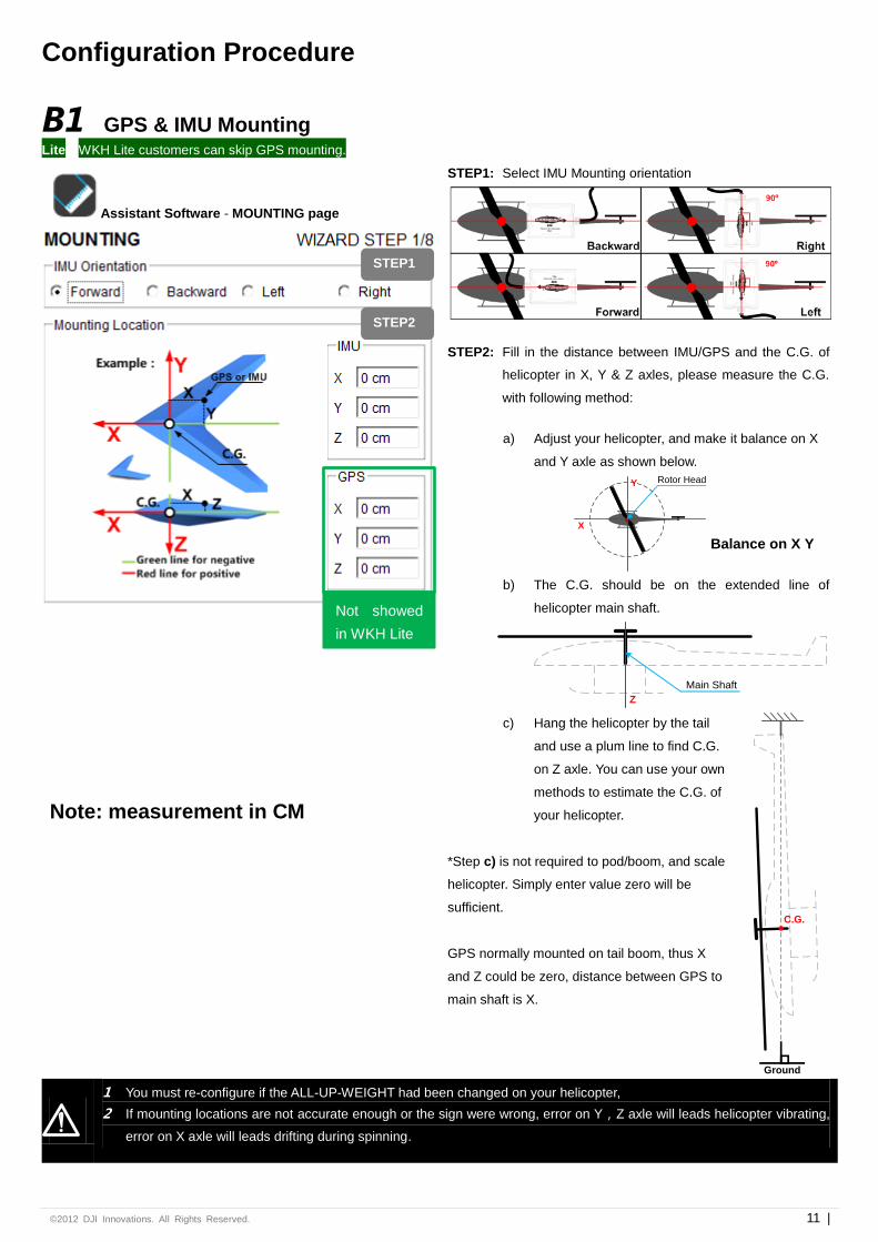
Configuration Procedure
B1 GPS & IMU Mounting Lite WKH Lite customers can skip GPS mounting.
Assistant Software - MOUNTING page
STEP1: Select IMU Mounting orientation
STEP2: Fill in the distance between IMU/GPS and the C.G. of
helicopter in X, Y & Z axles, please measure the C.G.
with following method:
a) Adjust your helicopter, and make it balance on X
and Y axle as shown below.
X
Y Rotor Head
Balance on X Y
b) The C.G. should be on the extended line of
helicopter main shaft.
Main Shaft
Z
c) Hang the helicopter by the tail
and use a plum line to find C.G.
on Z axle. You can use your own
methods to estimate the C.G. of
your helicopter.
*Step c) is not required to pod/boom, and scale
helicopter. Simply enter value zero will be
sufficient.
GPS normally mounted on tail boom, thus X
and Z could be zero, distance between GPS to
main shaft is X.
C.G.
Ground
Note: measurement in CM
1 You must re-configure if the ALL-UP-WEIGHT had been changed on your helicopter,
2 If mounting locations are not accurate enough or the sign were wrong, error on Y,Z axle will leads helicopter vibrating,
error on X axle will leads drifting during spinning.
STEP1
STEP2
Not showed
in WKH Lite
©2012 DJI Innovations. All Rights Reserved. 12 |
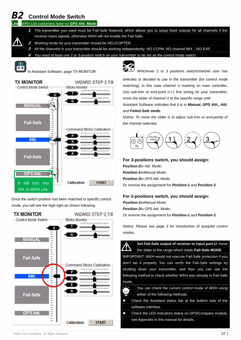
B2 Control Mode Switch Lite WKH Lite customers have no GPS Atti. Mode.
1 The transmitter you used must be Fail-Safe featured, which allows you to setup fixed outputs for all channels if the
receiver loses signals, otherwise WKH will not enable the Fail-Safe.
2 Working mode for your transmitter should be HELICOPTER.
3 All the channels in your transmitter should be working independently: NO CCPM, NO channel MIX,NO EXP.
4 You need at least one 2 or 3-position switch on your transmitter to be set as the control mode switch.
In Assistant Software, page TX-MONITOR:
1
2
3
Once the switch position has been matched to specific control
mode, you will see the high-light as shown following.
TX Whichever 2 or 3 positions switch/channel user has
selected or decided to use in the transmitter (for control mode
switching), in this case channel U marking on main controller.
Use sub-trim or end-point (+/-) fine tuning on your transmitter,
move the slider of channel U to the specific range until
Assistant Software indicates that it is in Manual, GPS Atti., Atti.
and Failed-Safe mode.
Notice: To move the slider is to adjust sub-trim or end-points of
the channel selected.
Tx
1 2 33 Position
Switch
For 3-positions switch, you should assign:
Position-2to Atti. Mode;
Position-1toManual Mode;
Position-3to GPS Atti. Mode;
Or reverse the assignment for Position-1 and Position-3.
For 2-positions switch, you should assign:
Position-1toManual Mode;
Position-3to GPS Atti. Mode;
Or reverse the assignment for Position-1 and Position-3.
Notice: Please see page 3 for introduction of autopilot control
modes.
Set Fail-Safe output of receiver to input port-U, move
the slider to the range which reads Fail-Safe MODE.
IMPORTANT: WKH would not execute Fail-Safe protection if you
don’t set it properly. You can verify the Fail-Safe settings by
shutting down your transmitter, and then you can use the
following method to check whether WKH was already in Fail-Safe
mode.
You can check the current control mode of WKH using
either of the following methods:
Check the Assistant status bar at the bottom side of the
software interface.
Check the LED indicators status on GPS/Compass module,
see Appendix in this manual for details.
It will turn into
Atti. in WKH Lite.
©2012 DJI Innovations. All Rights Reserved. 13 |
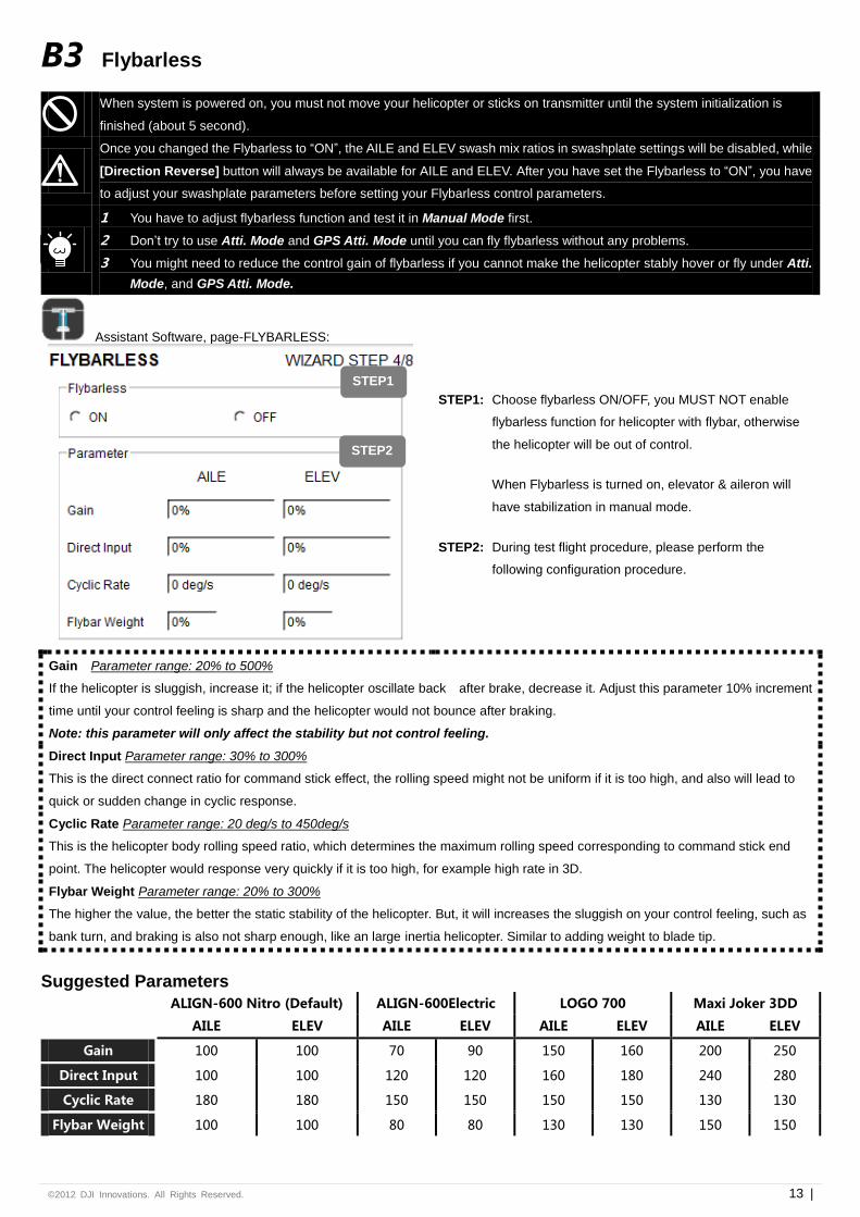
B3 Flybarless
When system is powered on, you must not move your helicopter or sticks on transmitter until the system initialization is
finished (about 5 second).
Once you changed the Flybarless to “ON”, the AILE and ELEV swash mix ratios in swashplate settings will be disabled, while
[Direction Reverse] button will always be available for AILE and ELEV. After you have set the Flybarless to “ON”, you have
to adjust your swashplate parameters before setting your Flybarless control parameters.
1 You have to adjust flybarless function and test it in Manual Mode first.
2 Don’t try to use Atti. Mode and GPS Atti. Mode until you can fly flybarless without any problems.
3 You might need to reduce the control gain of flybarless if you cannot make the helicopter stably hover or fly under Atti.
Mode, and GPS Atti. Mode.
Assistant Software, page-FLYBARLESS:
STEP1: Choose flybarless ON/OFF, you MUST NOT enable
flybarless function for helicopter with flybar, otherwise
the helicopter will be out of control.
When Flybarless is turned on, elevator & aileron will
have stabilization in manual mode.
STEP2: During test flight procedure, please perform the
following configuration procedure.
Gain Parameter range: 20% to 500%
If the helicopter is sluggish, increase it; if the helicopter oscillate back after brake, decrease it. Adjust this parameter 10% increment
time until your control feeling is sharp and the helicopter would not bounce after braking.
Note: this parameter will only affect the stability but not control feeling.
Direct Input Parameter range: 30% to 300%
This is the direct connect ratio for command stick effect, the rolling speed might not be uniform if it is too high, and also will lead to
quick or sudden change in cyclic response.
Cyclic Rate Parameter range: 20 deg/s to 450deg/s
This is the helicopter body rolling speed ratio, which determines the maximum rolling speed corresponding to command stick end
point. The helicopter would response very quickly if it is too high, for example high rate in 3D.
Flybar Weight Parameter range: 20% to 300%
The higher the value, the better the static stability of the helicopter. But, it will increases the sluggish on your control feeling, such as
bank turn, and braking is also not sharp enough, like an large inertia helicopter. Similar to adding weight to blade tip.
Suggested Parameters
ALIGN-600 Nitro (Default) ALIGN-600Electric LOGO 700 Maxi Joker 3DD
AILE ELEV AILE ELEV AILE ELEV AILE ELEV
Gain 100 100 70 90 150 160 200 250
Direct Input 100 100 120 120 160 180 240 280
Cyclic Rate 180 180 150 150 150 150 130 130
Flybar Weight 100 100 80 80 130 130 150 150
STEP1
STEP2
©2012 DJI Innovations. All Rights Reserved. 14 |
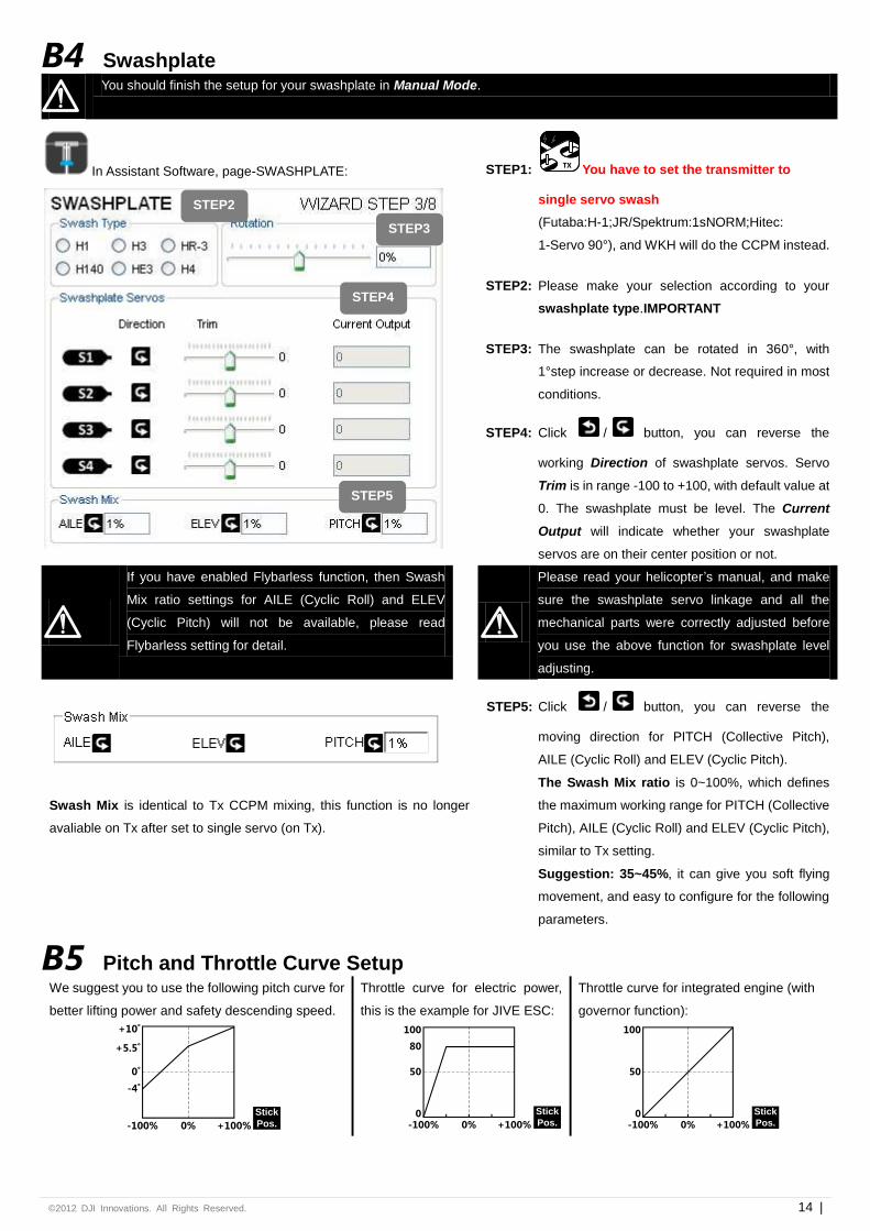
B4 Swashplate
You should finish the setup for your swashplate in Manual Mode.
In Assistant Software, page-SWASHPLATE:
STEP1: TX You have to set the transmitter to
single servo swash
(Futaba:H-1;JR/Spektrum:1sNORM;Hitec:
1-Servo 90°), and WKH will do the CCPM instead.
STEP2: Please make your selection according to your
swashplate type.IMPORTANT
STEP3: The swashplate can be rotated in 360°, with
1°step increase or decrease. Not required in most
conditions.
STEP4: Click / button, you can reverse the
working Direction of swashplate servos. Servo
Trim is in range -100 to +100, with default value at
0. The swashplate must be level. The Current
Output will indicate whether your swashplate
servos are on their center position or not.
If you have enabled Flybarless function, then Swash
Mix ratio settings for AILE (Cyclic Roll) and ELEV
(Cyclic Pitch) will not be available, please read
Flybarless setting for detail.
Please read your helicopter’s manual, and make
sure the swashplate servo linkage and all the
mechanical parts were correctly adjusted before
you use the above function for swashplate level
adjusting.
Swash Mix is identical to Tx CCPM mixing, this function is no longer
avaliable on Tx after set to single servo (on Tx).
STEP5: Click / button, you can reverse the
moving direction for PITCH (Collective Pitch),
AILE (Cyclic Roll) and ELEV (Cyclic Pitch).
The Swash Mix ratio is 0~100%, which defines
the maximum working range for PITCH (Collective
Pitch), AILE (Cyclic Roll) and ELEV (Cyclic Pitch),
similar to Tx setting.
Suggestion: 35~45%, it can give you soft flying
movement, and easy to configure for the following
parameters.
B5 Pitch and Throttle Curve Setup We suggest you to use the following pitch curve for
better lifting power and safety descending speed.
Stick
Pos.-100% 0% +100%
+10˚
-4˚
+5.5˚
0˚
Throttle curve for electric power,
this is the example for JIVE ESC:
-100% 0% +100%
50
0
80
100
Stick
Pos.
Throttle curve for integrated engine (with
governor function):
50
0
100
-100% 0% +100%
Stick
Pos.
STEP2
STEP3
STEP4
STEP5
©2012 DJI Innovations. All Rights Reserved. 15 |
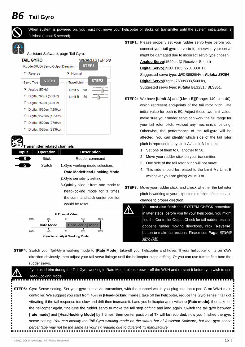
B6 Tail Gyro
When system is powered on, you must not move your helicopter or sticks on transmitter until the system initialization is
finished (about 5 second).
Assistant Software, page-Tail Gyro:
STEP1: Please properly set your rudder servo type before you
connect your tail-gyro servo to it, otherwise your servo
might be damaged due to incorrect servo type chosen.
Analog Servo(1520us @ Receiver Speed)
Digital Servo(1520us165, 270, 333Hz),
Suggested servo type: JRDS8925HV;Futaba S9254
Digital Servo(Digital-760us333,560Hz),
Suggested servo type: Futaba BLS251 / BLS351.
STEP2: We have [Limit A] and [Limit B](Range:-140 to +140),
which represent end-points of the tail rotor pitch. The
initial value for both is 50. Adjust these two limit value,
make sure your rudder servo can work the full range for
your tail rotor pitch, without any mechanical binding.
Otherwise, the performance of the tail-gyro will be
affected. You can identify which side of the tail rotor
pitch is represented by Limit A / Limit B like this:
1. Set one of them to 0, another to 50.
2. Move your rudder stick on your transmitter.
3. One side of the tail rotor pitch will not move.
4. This side should be related to the Limit A / Limit B
whichever you are giving value 0 to.
STEP3: Move your rudder stick, and check whether the tail rotor
pitch is working to your expected direction. If not, please
change to proper direction.
TX Transmitter related channels
Input Operation Description
R
Stick Rudder command
G
Switch 1. Gyro working mode selection:
Rate Mode/Head-Locking Mode
2. Gyro sensitivity setting
3. Quickly slide it from rate mode to
head-locking mode for 3 times,
the command stick center position
would be reset.
You must also finish the SYSTEM CHECK procedure
in later steps, before you fly your helicopter. You might
find the Controller Output Check for tail rudder result in
opposite rudder moving directions, click [Reverse]
button to make corrections. Please see Page 错误!未
定义书签。.
Rate Mode Head-locking Mode
G Channel Value
Gyro Sensitivity & Working Mode
0% 50% 100%
0% 50% 100%50%100%
50%100%
STEP4: Switch your Tail-Gyro working mode to [Rate Mode], take-off your helicopter and hover. If your helicopter drifts on YAW
direction obviously, then adjust your tail servo linkage until the helicopter stops drifting. Or you can use trim to fine-tune the
rudder servo.
If you used trim during the Tail-Gyro working in Rate Mode, please power off the WKH and re-start it before you wish to use
Head-Locking Mode.
STEP5: Gyro Sense setting: Set your gyro sense via transmitter, with the channel which you plug into input port-G on WKH main
controller. We suggest you start from 45% in [Head-locking mode], take off the helicopter, reduce the Gyro sense if tail got
vibrating; if the tail response too slow and drift then increase it. Land you helicopter and switch to [Rate mode], then take off
the helicopter again, fine-tune the rudder servo to make the tail stop drifting and land again. Switch the tail gyro between
[rate mode] and [Head-locking Mode] by 3 times, then center position of Tx will be recorded, now you finished the gyro
sense setting. You can identify the Tail-Gyro working mode on the status bar of Assistant Software, but that gyro sense
percentage may not be the same as your Tx reading due to different Tx manufacture.
STEP3
STEP1 STEP2
©2012 DJI Innovations. All Rights Reserved. 16 |
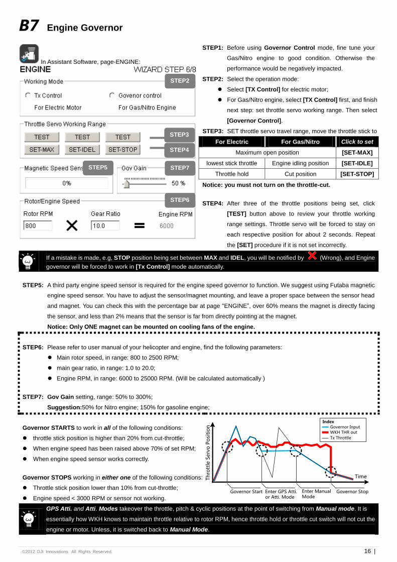
B7 Engine Governor
In Assistant Software, page-ENGINE:
STEP1: Before using Governor Control mode, fine tune your
Gas/Nitro engine to good condition. Otherwise the
performance would be negatively impacted.
STEP2: Select the operation mode:
Select [TX Control] for electric motor;
For Gas/Nitro engine, select [TX Control] first, and finish
next step: set throttle servo working range. Then select
[Governor Control].
STEP3: SET throttle servo travel range, move the throttle stick to
For Electric For Gas/Nitro Click to set
Maximum open position [SET-MAX]
lowest stick throttle Engine idling position [SET-IDLE]
Throttle hold Cut position [SET-STOP]
Notice: you must not turn on the throttle-cut.
STEP4: After three of the throttle positions being set, click
[TEST] button above to review your throttle working
range settings. Throttle servo will be forced to stay on
each respective position for about 2 seconds. Repeat
the [SET] procedure if it is not set incorrectly.
If a mistake is made, e.g, STOP position being set between MAX and IDEL, you will be notified by (Wrong), and Engine
governor will be forced to work in [Tx Control] mode automatically.
STEP5: A third party engine speed sensor is required for the engine speed governor to function. We suggest using Futaba magnetic
engine speed sensor. You have to adjust the sensor/magnet mounting, and leave a proper space between the sensor head
and magnet. You can check this with the percentage bar at page “ENGINE”, over 60% means the magnet is directly facing
the sensor, and less than 2% means that the sensor is far from directly pointing at the magnet.
Notice: Only ONE magnet can be mounted on cooling fans of the engine.
STEP6: Please refer to user manual of your helicopter and engine, find the following parameters:
Main rotor speed, in range: 800 to 2500 RPM;
main gear ratio, in range: 1.0 to 20.0;
Engine RPM, in range: 6000 to 25000 RPM. (Will be calculated automatically )
STEP7: Gov Gain setting, range: 50% to 300%;
Suggestion:50% for Nitro engine; 150% for gasoline engine;
Governor STARTS to work in all of the following conditions:
throttle stick position is higher than 20% from cut-throttle;
When engine speed has been raised above 70% of set RPM;
When engine speed sensor works correctly.
Governor STOPS working in either one of the following conditions:
Throttle stick position lower than 10% from cut-throttle;
Engine speed < 3000 RPM or sensor not working.
TimeTh
rott
le S
erv
o P
osi
tio
n
Governor Start Enter GPS Atti. or Atti. Mode
Enter Manual Mode
Governor Stop
Index
WKH THR out
Tx Throttle
Governor Input
GPS Atti. and Atti. Modes takeover the throttle, pitch & cyclic positions at the point of switching from Manual mode. It is
essentially how WKH knows to maintain throttle relative to rotor RPM, hence throttle hold or throttle cut switch will not cut the
engine or motor. Unless, it is switched back to Manual Mode.
STEP2
STEP7
STEP6
STEP3
STEP4
STEP5
©2012 DJI Innovations. All Rights Reserved. 17 |
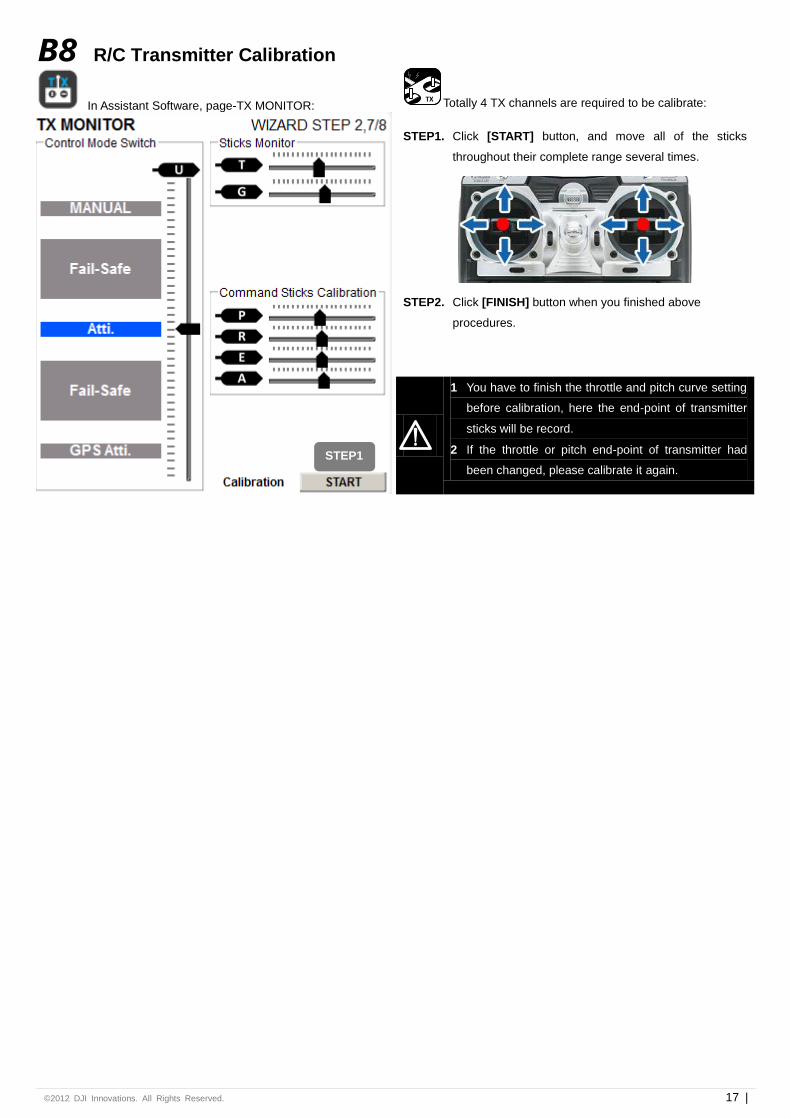
B8 R/C Transmitter Calibration
In Assistant Software, page-TX MONITOR:
TX Totally 4 TX channels are required to be calibrate:
STEP1. Click [START] button, and move all of the sticks
throughout their complete range several times.
STEP2. Click [FINISH] button when you finished above
procedures.
1 You have to finish the throttle and pitch curve setting
before calibration, here the end-point of transmitter
sticks will be record.
2 If the throttle or pitch end-point of transmitter had
been changed, please calibrate it again.
STEP1
©2012 DJI Innovations. All Rights Reserved. 18 |
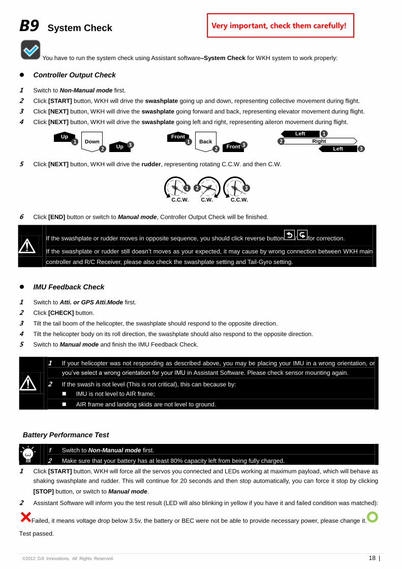
B9 System Check
You have to run the system check using Assistant software–System Check for WKH system to work properly:
Controller Output Check
1 Switch to Non-Manual mode first.
2 Click [START] button, WKH will drive the swashplate going up and down, representing collective movement during flight.
3 Click [NEXT] button, WKH will drive the swashplate going forward and back, representing elevator movement during flight.
4 Click [NEXT] button, WKH will drive the swashplate going left and right, representing aileron movement during flight.
Up1 Down
2 Up 3
Front1 Back
2 Front 3
Right
Left 1
2
Left 3
5 Click [NEXT] button, WKH will drive the rudder, representing rotating C.C.W. and then C.W.
1
C.C.W.
1
C.C.W.
31
C.W.
32
6 Click [END] button or switch to Manual mode, Controller Output Check will be finished.
IMU Feedback Check
1 Switch to Atti. or GPS Atti.Mode first.
2 Click [CHECK] button.
3 Tilt the tail boom of the helicopter, the swashplate should respond to the opposite direction.
4 Tilt the helicopter body on its roll direction, the swashplate should also respond to the opposite direction.
5 Switch to Manual mode and finish the IMU Feedback Check.
1 If your helicopter was not responding as described above, you may be placing your IMU in a wrong orientation, or
you’ve select a wrong orientation for your IMU in Assistant Software. Please check sensor mounting again.
2 If the swash is not level (This is not critical), this can because by:
IMU is not level to AIR frame;
AIR frame and landing skids are not level to ground.
Battery Performance Test
1 Switch to Non-Manual mode first.
2 Make sure that your battery has at least 80% capacity left from being fully charged.
1 Click [START] button, WKH will force all the servos you connected and LEDs working at maximum payload, which will behave as
shaking swashplate and rudder. This will continue for 20 seconds and then stop automatically, you can force it stop by clicking
[STOP] button, or switch to Manual mode.
2 Assistant Software will inform you the test result (LED will also blinking in yellow if you have it and failed condition was matched):
Failed, it means voltage drop below 3.5v, the battery or BEC were not be able to provide necessary power, please change it.
Test passed.
If the swashplate or rudder moves in opposite sequence, you should click reverse button / for correction.
If the swashplate or rudder still doesn’t moves as your expected, it may cause by wrong connection between WKH main
controller and R/C Receiver, please also check the swashplate setting and Tail-Gyro setting.
Very important, check them carefully!
©2012 DJI Innovations. All Rights Reserved. 19 |
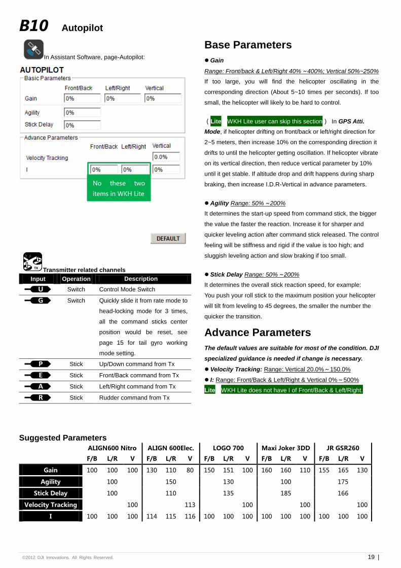
B10 Autopilot
In Assistant Software, page-Autopilot:
Base Parameters
Gain
Range: Front/back & Left/Right 40%~400%; Vertical 50%~250%
If too large, you will find the helicopter oscillating in the
corresponding direction (About 5~10 times per seconds). If too
small, the helicopter will likely to be hard to control.
(Lite WKH Lite user can skip this section) In GPS Atti.
Mode, if helicopter drifting on front/back or left/right direction for
2~5 meters, then increase 10% on the corresponding direction it
drifts to until the helicopter getting oscillation. If helicopter vibrate
on its vertical direction, then reduce vertical parameter by 10%
until it get stable. If altitude drop and drift happens during sharp
braking, then increase I.D.R-Vertical in advance parameters.
Agility Range: 50%~200%
It determines the start-up speed from command stick, the bigger
the value the faster the reaction. Increase it for sharper and
quicker leveling action after command stick released. The control
feeling will be stiffness and rigid if the value is too high; and
sluggish leveling action and slow braking if too small.
Stick Delay Range: 50%~200%
It determines the overall stick reaction speed, for example:
You push your roll stick to the maximum position your helicopter
will tilt from leveling to 45 degrees, the smaller the number the
quicker the transition.
Advance Parameters
The default values are suitable for most of the condition. DJI
specialized guidance is needed if change is necessary.
Velocity Tracking: Range: Vertical 20.0%~150.0%
I: Range: Front/Back & Left/Right & Vertical 0%~500%
Lite WKH Lite does not have I of Front/Back & Left/Right.
TX Transmitter related channels
Input Operation Description
U
Switch Control Mode Switch
G
Switch Quickly slide it from rate mode to
head-locking mode for 3 times,
all the command sticks center
position would be reset, see
page 15 for tail gyro working
mode setting.
P
Stick Up/Down command from Tx
E
Stick Front/Back command from Tx
A
Stick Left/Right command from Tx
R
Stick Rudder command from Tx
Suggested Parameters
ALIGN600 Nitro ALIGN 600Elec. LOGO 700 Maxi Joker 3DD JR GSR260
F/B L/R V F/B L/R V F/B L/R V F/B L/R V F/B L/R V
Gain 100 100 100 130 110 80 150 151 100 160 160 110 155 165 130
Agility 100 150 130 100 175
Stick Delay 100 110 135 185 166
Velocity Tracking 100 113 100 100 100
I 100 100 100 114 115 116 100 100 100 100 100 100 100 100 100
No these two
items in WKH Lite
©2012 DJI Innovations. All Rights Reserved. 20 |
Flight
C1 Digital Compass Calibration Lite WKH Lite customers can skip this step.
Why calibrate the compass?
Ferromagnetic substances placed on helicopter or around its
working environment will affect the reading of earth magnetic
for digital compass, it also reduces the accuracy of the
helicopter control, or even reads incorrect heading.
Calibration will eliminate such influences, and ensure WKH
system performs well in a non-ideal magnetic environment.
When to do it?
1 The first time you install WKH on your helicopter.
2 When the helicopter mechanical setup is changed:
a) If the GPS/Compass module is re-positioned.
b) If electronic devices are added/removed/
re-positioned (Main Controller, servos, batteries, etc).
c) When the mechanical structure of the helicopter is
changed.
3 If the flight direction appears to be shifting (meaning the
helicopter doesn’t “fly straight”).
4 The LED indicator often indicates abnormality blinking
when the helicopter yaws. (It is normal for this to happen
only occasionally.)
Where to do it?
Do the calibration in an open area, away from parked cars,
metal railings, and any metal around. Sometimes a bunch of
keys in your pocket might affect calibration.
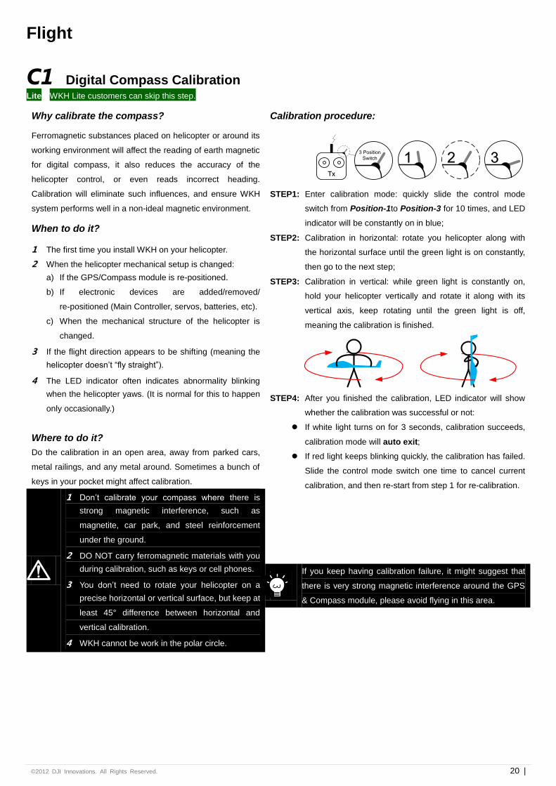
Calibration procedure:
Tx
1 2 33 Position
Switch
STEP1: Enter calibration mode: quickly slide the control mode
switch from Position-1to Position-3 for 10 times, and LED
indicator will be constantly on in blue;
STEP2: Calibration in horizontal: rotate you helicopter along with
the horizontal surface until the green light is on constantly,
then go to the next step;
STEP3: Calibration in vertical: while green light is constantly on,
hold your helicopter vertically and rotate it along with its
vertical axis, keep rotating until the green light is off,
meaning the calibration is finished.
STEP4: After you finished the calibration, LED indicator will show
whether the calibration was successful or not:
If white light turns on for 3 seconds, calibration succeeds,
calibration mode will auto exit;
If red light keeps blinking quickly, the calibration has failed.
Slide the control mode switch one time to cancel current
calibration, and then re-start from step 1 for re-calibration.
1 Don’t calibrate your compass where there is
strong magnetic interference, such as
magnetite, car park, and steel reinforcement
under the ground.
2 DO NOT carry ferromagnetic materials with you
during calibration, such as keys or cell phones.
3 You don’t need to rotate your helicopter on a
precise horizontal or vertical surface, but keep at
least 45° difference between horizontal and
vertical calibration.
4 WKH cannot be work in the polar circle.
If you keep having calibration failure, it might suggest that
there is very strong magnetic interference around the GPS
& Compass module, please avoid flying in this area.
©2012 DJI Innovations. All Rights Reserved. 21 |
C2 MANUAL MODE Test Flight
1 When the system is powered on, DO NOT moves your helicopter or sticks on transmitter until the system initialization is
finished (about 5 seconds).
2 Don’t switch to Atti. Mode or GPS Atti. Mode during Manual Mode Test Flight. Go through this section first, and read
about how to do Autopilot Test Flight on Page 23.
1 Fly the helicopter. Trim transmitter such that the
helicopter hovers stably.
2 You have to adjust the following parameters to
achieve the best performance of your
helicopter.
Flybarless parameters, if you’ve enabled
Flybarless, see Page 13 for details.
Tail Gyro sense, see Page 15 for details.
Engine speed, if you are using Gasoline /
Nitro engine, see Page 16for details.
3 Adjust Pitch curve on transmitter, so that the
helicopter hovers at about mid-stick.
4 Set correct fail safe output on all channels of
your R/C Transmitter/Receiver.
5 Verify Fail safe output of your transmitter on
status bar in Assistant Software. IMPORTANT!
STEP1: Check all the connection and wiring connected firmly, and
make sure they are in good condition;
STEP2: Make sure your batteries are fully charged for your
transmitter, WKH and all the devices on your helicopter;
STEP3: Turn on the transmitter first;
STEP4: Power on WKH and all the rest of electric devices on
helicopter, except brushless motor controller;
STEP5: Check the LED indicator, if red LED blinks quickly &
continually, then system start-up has failed; you have to
place you helicopter horizontally and power on again. See
Appendix for details about LED indicator;
STEP6: Slide the control mode switch on your transmitter to make
sure it is working properly. Check LED indicator to specify
the current working mode. See Appendix for details about
LED indicator;
STEP7: Others system failure and error will also be displayed by
LED indicator, See Appendix for details;
STEP8: If everything checked, and without any problems, switch
the system to Manual Mode, move all the sticks on your
transmitter to check whether the helicopter is correctly
responding to your commands;
STEP9: Start the engine or power on the brushless motor controller;
STEP10: Take-off and fly your helicopter in Manual Mode, before
switching to other modes.
The Fail-Safe (Auto Hovering or Level) has not been
activated yet, goes through this section first and read
about how to activate it on Page 22.
©2012 DJI Innovations. All Rights Reserved. 22 |
C3 Fail-Safe WKH can detect the fail safe output from your receiver, if you have pre-set fail safe output correctly. Once your helicopter lost signal
from the transmitter, Fail-Safe function will control the helicopter automatically and save it in most of the conditions.
1 The Fail-Safe (Auto Hover or Level) will not be activated, until you’ve correctly Pre-set Transmitter Command Stick
Center Position.
2 The Fail-Safe functions will not be working correctly if you have not finished the Auto Mode Test Flight. Please see
Autopilot Test Flight on Page 23 for details.
3 You must perform the following setting under Manual Mode.
4 If GPS signal reception is bad or you are using WKH Lite, auto level function will be triggered, but no position holding.
5 If you have already setup Fail-Safe successfully, then main rotor will start if you switch off Tx when your helicopter is
powered on.
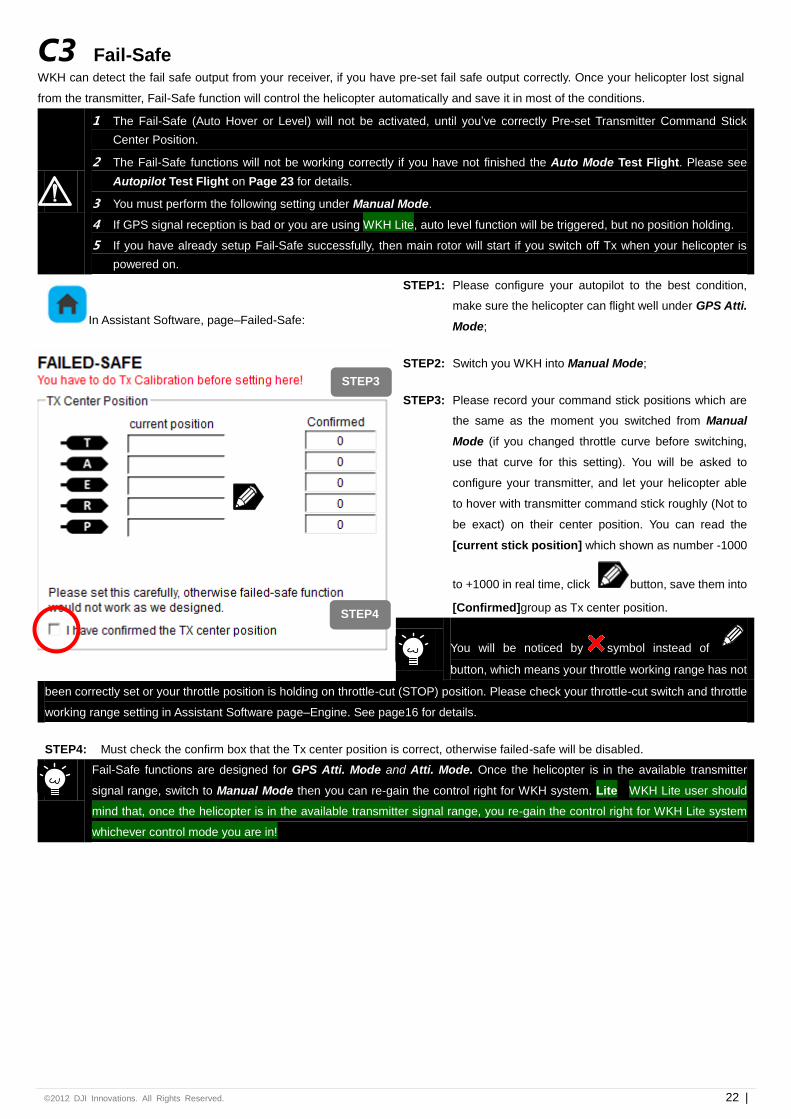
In Assistant Software, page–Failed-Safe:
STEP1: Please configure your autopilot to the best condition,
make sure the helicopter can flight well under GPS Atti.
Mode;
STEP2: Switch you WKH into Manual Mode;
STEP3: Please record your command stick positions which are
the same as the moment you switched from Manual
Mode (if you changed throttle curve before switching,
use that curve for this setting). You will be asked to
configure your transmitter, and let your helicopter able
to hover with transmitter command stick roughly (Not to
be exact) on their center position. You can read the
[current stick position] which shown as number -1000
to +1000 in real time, click button, save them into
[Confirmed]group as Tx center position.
You will be noticed by symbol instead of
button, which means your throttle working range has not
been correctly set or your throttle position is holding on throttle-cut (STOP) position. Please check your throttle-cut switch and throttle
working range setting in Assistant Software page–Engine. See page16 for details.
STEP4: Must check the confirm box that the Tx center position is correct, otherwise failed-safe will be disabled.
Fail-Safe functions are designed for GPS Atti. Mode and Atti. Mode. Once the helicopter is in the available transmitter
signal range, switch to Manual Mode then you can re-gain the control right for WKH system. Lite WKH Lite user should
mind that, once the helicopter is in the available transmitter signal range, you re-gain the control right for WKH Lite system
whichever control mode you are in!
STEP3
STEP4
©2012 DJI Innovations. All Rights Reserved. 23 |
C4 Autopilot Test Fight
WKH Test Flight (Lite WKH Lite user should skip this section to WKH Lite Test Flight section on next page)
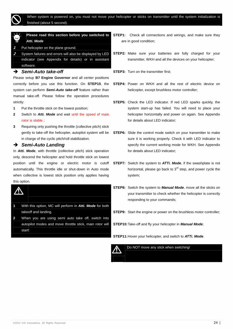
When system is powered on, you must not move your helicopter or sticks on transmitter until the system initialization is
finished (about 5 second).
Please read this section before you switched to
Atti. Mode and GPS Atti. Mode
1 Make sure the GPS signal is good, without red LED
blinking.
2 Please avoid using WKH system in the following areas,
where will GPS signal is most likely blocked:
Urban area with crowded buildings
Tunnels
Under bridges
3 Make sure the attitude of helicopter is in good condition,
without white LED blinking.
4 Other system failures and errors will also be displayed
by LED indicator (see Appendix for details) or in
assistant software.
5 If WKH has already acquired the GPS signal, you
cannot unplug GPS module directly without reboot and
fly in GPS Atti Mode.
STEP1: Check all connections and wirings, and make sure they are
in good condition;
STEP2: Make sure your batteries are fully charged for your
transmitter, WKH and all the devices on your helicopter;
STEP3: Turn on the transmitter first;
STEP4: Power on WKH and all the rest of electric device on
helicopter, except brushless motor controller;
STEP5: Check the LED indicator. If red LED sparks quickly, the
system start-up has failed. You will need to place your
helicopter horizontally and power on again. See Appendix
for details about LED indicator;
STEP6: You may find red LED blinking, indicating that WKH is
getting GPS satellite signal, please wait until red LED is off,
meaning WKH have found more than 7 GPS satellites, and
that it can work in its best condition. See Appendix for
details about LED indicator;
STEP7: Slide the control mode switch on your transmitter to make
sure it is working properly. Check it with LED indicator to
specify the current working mode for WKH. See Appendix
for details about LED indicator;
STEP8: Switch the system to GPS ATTi. Mode, if the swashplate is
not horizontal, please go back to 3rd
step, and power cycle
the system;
STEP9: Switch the system to Manual Mode, move all the sticks on
your transmitter to check whether the helicopter is correctly
responding to your commands;
STEP10: Start the engine or power on the brushless motor controller;
STEP11: Take-off and fly your helicopter in Manual Mode;
STEP12: Hover your helicopter, and switch to GPS ATTi. Mode.
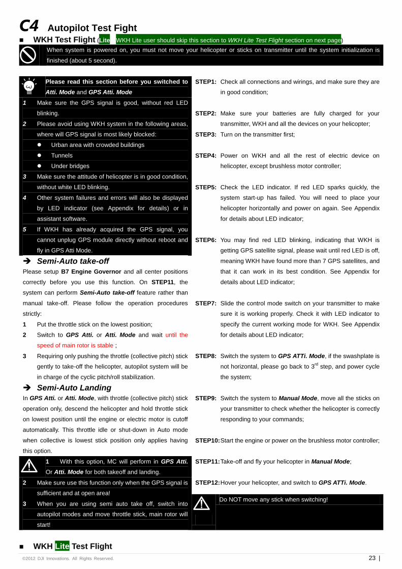
Semi-Auto take-off
Please setup B7 Engine Governor and all center positions
correctly before you use this function. On STEP11, the
system can perform Semi-Auto take-off feature rather than
manual take-off. Please follow the operation procedures
strictly:
1 Put the throttle stick on the lowest position;
2 Switch to GPS Atti. or Atti. Mode and wait until the
speed of main rotor is stable ;
3 Requiring only pushing the throttle (collective pitch) stick
gently to take-off the helicopter, autopilot system will be
in charge of the cyclic pitch/roll stabilization.
Semi-Auto Landing
In GPS Atti. or Atti. Mode, with throttle (collective pitch) stick
operation only, descend the helicopter and hold throttle stick
on lowest position until the engine or electric motor is cutoff
automatically. This throttle idle or shut-down in Auto mode
when collective is lowest stick position only applies having
this option.
1 With this option, MC will perform in GPS Atti.
Or Atti. Mode for both takeoff and landing.
2 Make sure use this function only when the GPS signal is
sufficient and at open area!
3 When you are using semi auto take off, switch into
autopilot modes and move throttle stick, main rotor will
start!
Do NOT move any stick when switching!
WKH Lite Test Flight
©2012 DJI Innovations. All Rights Reserved. 24 |
When system is powered on, you must not move your helicopter or sticks on transmitter until the system initialization is
finished (about 5 second).
Please read this section before you switched to
Atti. Mode
1 Put helicopter on the plane ground.
2 System failures and errors will also be displayed by LED
indicator (see Appendix for details) or in assistant
software.
STEP1: Check all connections and wirings, and make sure they
are in good condition;
STEP2: Make sure your batteries are fully charged for your
transmitter, WKH and all the devices on your helicopter;
STEP3: Turn on the transmitter first;
STEP4: Power on WKH and all the rest of electric device on
helicopter, except brushless motor controller;
STEP5: Check the LED indicator. If red LED sparks quickly, the
system start-up has failed. You will need to place your
helicopter horizontally and power on again. See Appendix
for details about LED indicator;
STEP6: Slide the control mode switch on your transmitter to make
sure it is working properly. Check it with LED indicator to
specify the current working mode for WKH. See Appendix
for details about LED indicator;
STEP7: Switch the system to ATTi. Mode, if the swashplate is not
horizontal, please go back to 3rd
step, and power cycle the
system;
STEP8: Switch the system to Manual Mode, move all the sticks on
your transmitter to check whether the helicopter is correctly
responding to your commands;
STEP9: Start the engine or power on the brushless motor controller;
STEP10: Take-off and fly your helicopter in Manual Mode;
STEP11: Hover your helicopter, and switch to ATTi. Mode.
Semi-Auto take-off
Please setup B7 Engine Governor and all center positions
correctly before you use this function. On STEP10, the
system can perform Semi-Auto take-off feature rather than
manual take-off. Please follow the operation procedures
strictly:
1 Put the throttle stick on the lowest position;
2 Switch to Atti. Mode and wait until the speed of main
rotor is stable ;
3 Requiring only pushing the throttle (collective pitch) stick
gently to take-off the helicopter, autopilot system will be
in charge of the cyclic pitch/roll stabilization.
Semi-Auto Landing
In Atti. Mode, with throttle (collective pitch) stick operation
only, descend the helicopter and hold throttle stick on lowest
position until the engine or electric motor is cutoff
automatically. This throttle idle or shut-down in Auto mode
when collective is lowest stick position only applies having
this option.
1 With this option, MC will perform in Atti. Mode for both
takeoff and landing.
2 When you are using semi auto take off, switch into
autopilot modes and move throttle stick, main rotor will
start!
Do NOT move any stick when switching!
©2012 DJI Innovations. All Rights Reserved. 25 |
Maintains
Firmware Upgrade
Please strictly follow the operation procedure for firmware upgrade, otherwise WKH might not work properly:
1. Make sure your computer is connected to the Internet.
2. Please close all the other applications during the firmware upgrade, including Anti-virus software and firewall.
3. Make sure the power supply is securely connected. DO NOT un-plug the power supply until firmware upgrade has finished.
4. Connect main controller to PC with micro-USB cable, DO NOT break connection until firmware upgrade is finished.
5. Run Software and wait for connection.
6. Select [TOOL][Firmware Upgrade].
7. DJI server will check your current firmware version, and get the latest firmware prepared for the unit.
8. If there is a firmware version more up-to-date than your current version, you will be able to click the upgrade button.
9. Wait until Assistant software reads “Finished”.
10. Please power cycle the unit after at least 5 seconds.
11. Your unit is up-to-date now.
After firmware upgrade, please re-configure WKH using Assistant software.
If it is notified that the network or DJI server is busy, please try again later with above procedures.
If firmware upgrade failed, WKH will enter <waiting for firmware upgrade status> automatically,
please try again with the above procedures.
Note: You will be asked to fill out contact information/register as user prior to any upgrades
Product Info
You can check the WKH product version via [ABOUT][Info].
Software version Firmware version IMU version Hardware ID
[S/N] is a 32 digits authorization code for unit function activations. We had already filled in the authorization code for your unit after
manufacture. You might be asking to fill in the new [S/N] in the future if you brought new function upgrades.
Fill-in the [S/N] and then click [Write] button.
If you filled in the invalid S/N over 30 times, your WKH will be locked and you have to contact our customer support.
©2012 DJI Innovations. All Rights Reserved. 26 |
Appendix
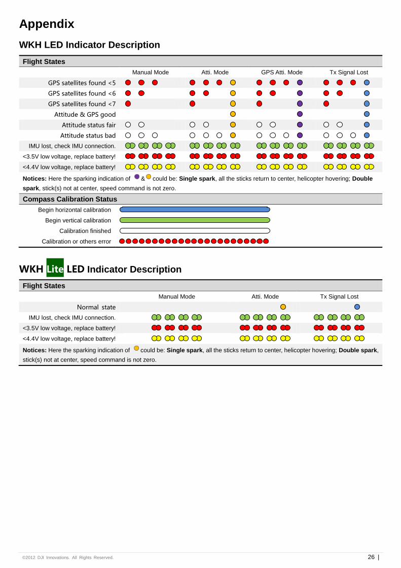
WKH LED Indicator Description
Flight States
Manual Mode Atti. Mode GPS Atti. Mode Tx Signal Lost
GPS satellites found <5
GPS satellites found <6
GPS satellites found <7
Attitude & GPS good
Attitude status fair
Attitude status bad
IMU lost, check IMU connection.
<3.5V low voltage, replace battery!
<4.4V low voltage, replace battery!
Notices: Here the sparking indication of & could be: Single spark, all the sticks return to center, helicopter hovering; Double
spark, stick(s) not at center, speed command is not zero.
Compass Calibration Status
Begin horizontal calibration
Begin vertical calibration
Calibration finished
Calibration or others error
WKH Lite LED Indicator Description
Flight States
Manual Mode Atti. Mode Tx Signal Lost
Normal state
IMU lost, check IMU connection.
<3.5V low voltage, replace battery!
<4.4V low voltage, replace battery!
Notices: Here the sparking indication of could be: Single spark, all the sticks return to center, helicopter hovering; Double spark,
stick(s) not at center, speed command is not zero.
©2012 DJI Innovations. All Rights Reserved. 27 |
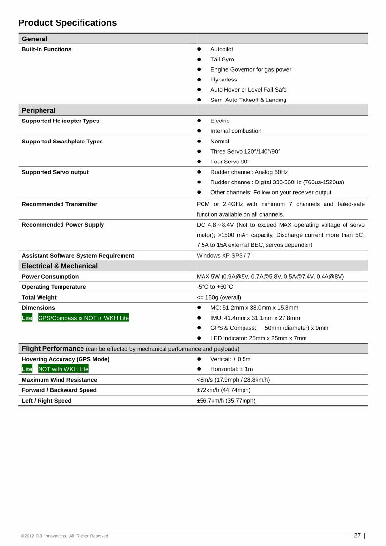
Product Specifications
General
Built-In Functions Autopilot
Tail Gyro
Engine Governor for gas power
Flybarless
Auto Hover or Level Fail Safe
Semi Auto Takeoff & Landing
Peripheral
Supported Helicopter Types Electric
Internal combustion
Supported Swashplate Types Normal
Three Servo 120°/140°/90°
Four Servo 90°
Supported Servo output Rudder channel: Analog 50Hz
Rudder channel: Digital 333-560Hz (760us-1520us)
Other channels: Follow on your receiver output
Recommended Transmitter PCM or 2.4GHz with minimum 7 channels and failed-safe
function available on all channels.
Recommended Power Supply DC 4.8~8.4V (Not to exceed MAX operating voltage of servo
motor); >1500 mAh capacity, Discharge current more than 5C;
7.5A to 15A external BEC, servos dependent
Assistant Software System Requirement Windows XP SP3 / 7
Electrical & Mechanical
Power Consumption MAX 5W (0.9A@5V, [email protected], [email protected], 0.4A@8V)
Operating Temperature -5°C to +60°C
Total Weight <= 150g (overall)
Dimensions MC: 51.2mm x 38.0mm x 15.3mm
Lite GPS/Compass is NOT in WKH Lite IMU: 41.4mm x 31.1mm x 27.8mm
GPS & Compass: 50mm (diameter) x 9mm
LED Indicator: 25mm x 25mm x 7mm
Flight Performance (can be effected by mechanical performance and payloads)
Hovering Accuracy (GPS Mode) Vertical: ± 0.5m
Lite NOT with WKH Lite Horizontal: ± 1m
Maximum Wind Resistance <8m/s (17.9mph / 28.8km/h)
Forward / Backward Speed ±72km/h (44.74mph)
Left / Right Speed ±56.7km/h (35.77mph)