Embed Size (px)
Citation preview
Workshop Manual
Models
30GSMEFS, 30GSPEFS
43GLPEFS, 43GiPEFS
50GLPEFS, 50GiPEFS
57GSPEFS, 57GSiPEFS
74GiPEFS, 74GSiPEFS
82GSiPEFS
DPX385XEFS, DPX415XEFS
Engine Components

iEngine/eng
ContentsGeneral Information .........................................................
General Engine Mechanical - V6 and V8 Models .............
3.0 GS Engines .................................................................
4.3 GL, GS and Gi Engines ...............................................
5.0 GL, Gi, 5.7 GS and GSi Engines .................................
7.4 Gi Engines ...................................................................
7.4 GSi and 8.2 GSi Engines ............................................
Steering System ................................................................
Throttle and Shift Control Systems .................................
Cooling Systems ...............................................................
Engine Removal and Installation .....................................
Safety ................................................................................
1
2
3
4
5
6
7
8
9
S
11
10

iiEngine/eng
iiiEngine/eng
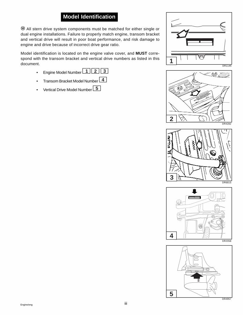
M All stern drive system components must be matched for either single ordual engine installations. Failure to properly match engine, transom bracketand vertical drive will result in poor boat performance, and risk damage toengine and drive because of incorrect drive gear ratio.
Model identification is located on the engine valve cover, and MUST corre-spond with the transom bracket and vertical drive numbers as listed in thisdocument.
• Engine Model Number 1 2 3
• Transom Bracket Model Number 4
• Vertical Drive Model Number 5
Model Identification
DR1145
DR4282
DR6815
DR2058
DR4957
1
2
4
5
3

ivEngine/eng
1-1Engine/eng
Section 1General Information
Table of Contents
1Battery Cable Requirements ........................................................... 1-40Belt Adjustments
Alternator ....................................................................................... 1-25Power Steering .............................................................................. 1-26
Belt Tension ...................................................................................... 1-24Compresion Pressure Limit Chart .................................................... 1-7Conversion Charts
Drill ................................................................................................. 1-42Metric ............................................................................................. 1-41
Crankcase Oil ................................................................................... 1-11Engine Break-in ................................................................................ 1-21Engine Compression Testing ............................................................ 1-5Engine Troubleshooting Guides ..................................................... 1-29Gasolines Containing Alcohol ........................................................ 1-10Gasoline Requirements ................................................................... 1-10Intake Manifold Vacuum Testing ....................................................... 1-8Introduction ........................................................................................ 1-220-Hour Check .................................................................................. 1-23Off-Season Storage Preparations ................................................... 1-13Oil Filter ............................................................................................. 1-12Periodic Maintenance Chart ............................................................ 1-44Positive Closed-Type Ventilation System ...................................... 1-27Power Steering Fluid Level ............................................................. 1-13Power Trim/Tilt Fluid Level .............................................................. 1-13Preparation for Boating After Storage ............................................ 1-20Steering System Lubrication ........................................................... 1-13Submerged Engine ........................................................................... 1-23Symbols ............................................................................................ 1-43Torque Specifications, General ....................................................... 1-40Troubleshooting - System Isolation ................................................ 1-28Tune-up Specifications .................................................................... 1-36Tuning the Engine .............................................................................. 1-5
Safety Warnings
Before working on any part of a Volvo Penta stern drive, read theSafety section at the end of this manual.
1-2 Engine/eng
Introduction
This service manual is divided into sections concerning various sys-tems and assemblies. Refer to the Contents to locate the section cov-ering the system or assembly requiring service. Each section title pagehas an additional listing that will describe the section’s contents in moredetail. Be sure to read the Safety Section at the end of this manual,and pay special attention to all safety warnings as they appear through-out the text. Since models are subject to change at any time, somephotos may not depict actual product.
Good Service Practice
Service required for stern drives is generally one of three kinds:
• Normal care and maintenance - which includes puttinga new stern drive into operation, storing engines, lubrica-tion, and care under special operating conditions suchas salt water and cold weather.
• Operating malfunctions - due to improper engine ordrive mounting, propeller condition or size, boat condi-tion, or the malfunction of some part of the engine. Thisincludes engine servicing procedures to keep the enginein prime operating condition.
• Complete disassembly and overhaul - such as majorservice or rebuilding a unit.
It is important to determine before disassembly just what the trouble isand how to correct it quickly, with minimum expense to the owner.
When repairing an assembly, the most reliable way to ensure a goodjob is to do a complete overhaul on that assembly, rather than just toreplace the bad part. Wear not readily apparent on other parts couldcause malfunction soon after the repair job. Repair kits and seal kitscontain all the parts needed to ensure a complete repair, to eliminateguesswork, and to save time.
Repair time can also be minimized by the use of special tools. VolvoPenta special tools are designed to perform service procedures uniqueto the product that cannot be completed using tools from other sources.They also speed repair work to help achieve service flat rate times. Insome cases, the use of substitute tools can damage the part.
Do not operate engine out of water even momentarily. Ifoperated in test tank, use proper test wheel. Failure to do so can dam-age supply pump, overheat engine, or allow excessive engine RPM.
1-3Engine/eng
Preparation for Service
Proper preparation is extremely helpful for efficient service work. A cleanwork area at the start of each job will minimize tools and parts becom-ing misplaced. Clean an engine that is excessively dirty before workstarts. Cleaning will occasionally uncover trouble sources. Obtain tools,instruments and parts needed for the job before work is started. Inter-rupting a job to locate special tools or repair kits is a needless delay.
Use proper lifting and handling equipment. Working on sterndrives without proper equipment can cause damage and personalinjury.
Always use clean fresh fuel when testing engines. Troubles can oftenbe traced to the use of old or dirty fuel.
Service Policy
It is a Volvo Penta policy to provide dealers with service knowledge sothey can give professional service demanded by today’s consumer. TheVolvo Penta Training Centers, frequent mailing of Service Bulletins, Let-ters and Promotions, Special Tools and this Service Manual representthe latest effort to assist dealers in giving consumers the best and mostprompt service possible. If a service question does not appear to beanswered in this manual, you are invited to write to the Volvo PentaService Department for additional help. Always be sure to give com-plete information, including engine model number and serial number.
When a brand-name product or specific tool is called for, another itemmay be used. However, the substitute must have equivalent character-istics, including type, strength, and material. You must determine if in-correct substitution could result in product malfunction and personalinjury to anyone. To avoid hazards, equivalent products which are usedmust meet all current U.S. Coast Guard Safety Regulations and ABYCstandards.
Safety Related
1-4 Engine/eng
Replacement Parts
When replacement parts are required, always use genuine VolvoPenta parts, or parts with equivalent characteristics, including type,strength, and material. Failure to do so may result in product malfunc-tion and possible injury to the operator and/or passengers.
Parts Catalogs
Parts Catalogs contain exploded views showing the correct assemblyof all parts, as well as a complete listing of the parts for replacement.These catalogs are helpful as a reference during disassembly and re-assembly, and are available from Volvo Penta Parts.
Special Service Tools
Volvo Penta has specially designed tools to simplify some of the dis-assembly and assembly operations. These tools are illustrated in thisService Manual, in many cases in actual use. All special tools can beorder from Volvo Penta Parts. Individual purchasers of Service Manu-als must order Special Tools through an authorized dealer.
Product References, Illustrations & Specifications
Volvo Penta reserves the right to make changes at anytime, withoutnotice, in specifications and models and also to discontinue models.The right is also reserved to change any specifications or parts at anytime without incurring any obligation to equip same on models manu-factured prior to date of such change. All information, illustrations andspecifications contained in this manual are based on the latest prod-uct information available at the time of printing. The right is reservedto make changes at anytime without notice.
All photographs and illustrations used in this manual may not depictactual models or equipment, but are intended as representative viewsfor reference only. The continuing accuracy of this manual cannot beguaranteed.
Safety Related
1-5Engine/eng
Tuning The Engine
The purpose of an engine tune-up is to restore power and performancethat has been lost through wear, corrosion or deterioration of one ormore parts or components. In the normal operation of an engine, thesechanges can take place gradually at a number of points, so that it isseldom advisable to attempt an improvement in performance by correc-tion of one or two items only. Time will be saved and more lasting re-sults will be obtained by following a definite and thorough procedure ofanalysis and correction of all items affecting power and performance.
Economical, trouble-free operation can better be ensured if a completetune-up is performed once every year, preferably in the spring. Compo-nents that affect power and performance can be divided into threegroups:
• Components affecting compression
• Components affecting ignition
• Components affecting fuel system
Tune-up procedures should cover these groups in the order given. Whilethe items affecting compression and ignition may be handled accordingto personal preference, correction of items in the fuel system groupshould not be attempted until all items affecting compression and igni-tion have been satisfactorily corrected. Most of the procedures for per-forming a complete engine tune-up will be covered in greater detail inthis manual. This section will deal mainly with the order of proceduresinvolved in tuning the engine.
Engine Compression Testing
During all work done around the engine, while the engine isrunning or being cranked, use extreme care to avoid getting fin-gers or clothing caught in any belts, pulleys, or other moving parts.
1. Visually inspect stern drive unit for leaks, missing parts or otherobvious defects. Replace deteriorated parts.
2. Compression check: Proper compression is essential for good en-gine performance. An engine with low or uneven compression cannotbe properly tuned.
a. Operate engine to normal operating temperature.
Engine must not be started and run without water for cooling.
Safety Related
1-6 Engine/eng
b. Remove any foreign matter from around spark plugs by blow-ing out with compressed air.
c. Remove and inspect all spark plugs. Install thread-type com-pression gauge in spark plug hole.
d. To Prevent Sparking:
• All Models Except 5.0 GL and 5.7 GS: Remove (grey)2-wire connector, with purple and grey wires, at ignitioncoil.
• 5.0 GL and 5.7 GS Models Only: Remove both distribu-tor primary wires from the ignition coil. Tape wire termi-nals to prevent accidental grounding.
e. With choke and/or throttle plates wide open, crank enginethrough at least four compression strokes.
Test Conclusion
The indicated compression pressures are considered normal if the low-est reading cylinder is within 75% of the highest.
Example:
If the highest pressure reading was 140 PSI, 75% of 140 is 105. There-fore, any cylinder reading less than 105 PSI indicates an improperlyseated valve, worn valve guides, piston, cylinder, or worn or brokenpiston rings. Any cylinder reading 105 PSI or greater is within specifi-cations, and compression is considered normal.
If one or more cylinders read low, squirt approximately one tablespoonof engine oil on top of the pistons in the low reading cylinders. Repeatcompression pressure check on the cylinders.
1. If compression improves considerably, the piston rings are at fault.
2. If compression does not improve, valves are sticking or seatingpoorly, or valve guides are worn.
3. If two adjacent cylinders indicate low compression pressures andsquirting oil on the pistons does not increase the compression, thecause may be a cylinder head gasket leak between the cylinders. Thisproblem could allow engine oil and/or coolant to enter the cylinders.
Safety Related
1-7Engine/eng
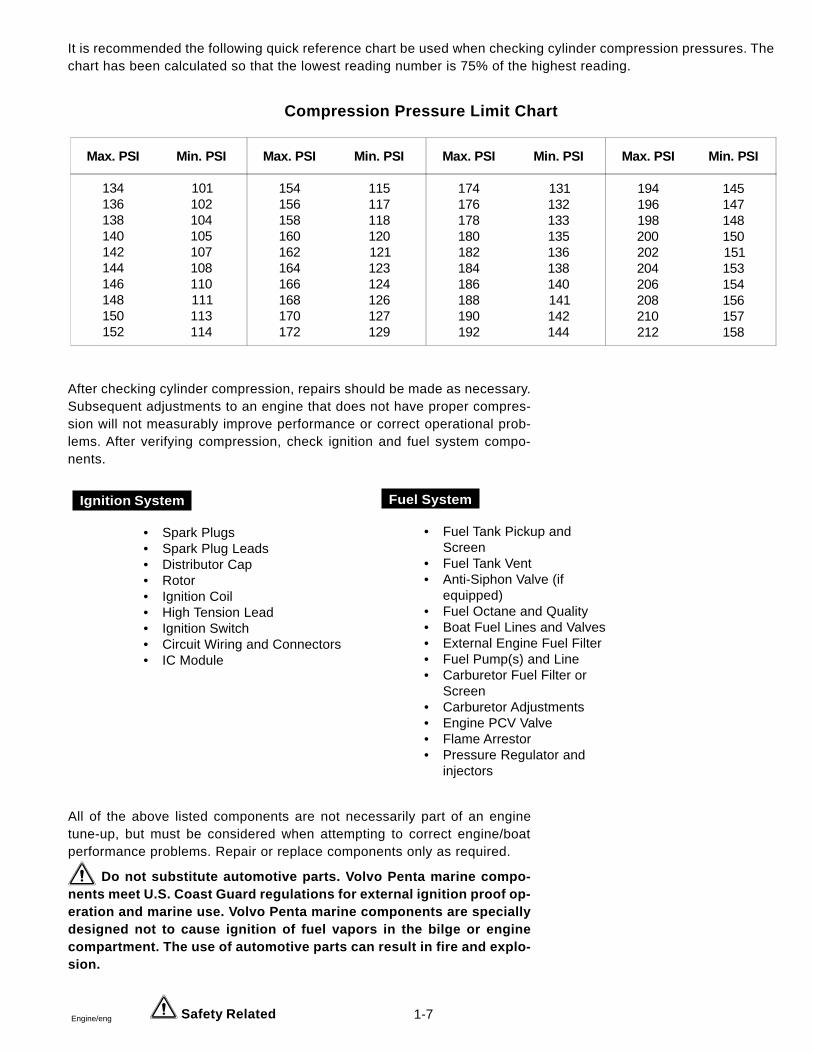
It is recommended the following quick reference chart be used when checking cylinder compression pressures. Thechart has been calculated so that the lowest reading number is 75% of the highest reading.
Compression Pressure Limit Chart
After checking cylinder compression, repairs should be made as necessary.Subsequent adjustments to an engine that does not have proper compres-sion will not measurably improve performance or correct operational prob-lems. After verifying compression, check ignition and fuel system compo-nents.
All of the above listed components are not necessarily part of an enginetune-up, but must be considered when attempting to correct engine/boatperformance problems. Repair or replace components only as required.
Do not substitute automotive parts. Volvo Penta marine compo-nents meet U.S. Coast Guard regulations for external ignition proof op-eration and marine use. Volvo Penta marine components are speciallydesigned not to cause ignition of fuel vapors in the bilge or enginecompartment. The use of automotive parts can result in fire and explo-sion.
• Fuel Tank Pickup andScreen
• Fuel Tank Vent• Anti-Siphon Valve (if
equipped)• Fuel Octane and Quality• Boat Fuel Lines and Valves• External Engine Fuel Filter• Fuel Pump(s) and Line• Carburetor Fuel Filter or
Screen• Carburetor Adjustments• Engine PCV Valve• Flame Arrestor• Pressure Regulator and
injectors
• Spark Plugs• Spark Plug Leads• Distributor Cap• Rotor• Ignition Coil• High Tension Lead• Ignition Switch• Circuit Wiring and Connectors• IC Module
Ignition System Fuel System
Safety Related
Max. PSI Min. PSI Max. PSI Min. PSI Max. PSI Min. PSI Max. PSI Min. PSI
134136138140142144146148150152
101102104105107108110111113114
154156158160162164166168170172
115117118120121123124126127129
174176178180182184186188190192
131132133135136138140141142144
194196198200202204206208210212
145147148150151153154156157158
1-8 Engine/eng
Intake Manifold Vacuum Testing
Test Procedures
1. Install a vacuum gauge to a good intake manifold source, followingthe gauge manufacturer’s instructions. Start and warm up the engine.
2. Observe the vacuum gauge while operating the engine over a rangeof engine speeds.
Test Results
1. A steady vacuum reading between 18 and 22 in. Hg. (60,7-74,3kPa) at idle indicates an engine in good mechanical condition.
2. A vacuum reading below 18 in. Hg. (60,7 kPa) at idle, indicates anengine that is not developing enough vacuum. Further testing for basemechanical problems is needed.
3. Possible causes of low intake manifold vacuum are late ignition tim-ing, low compression, poor engine sealing, leaks at vacuum lines andconnections or bad MAP sensor.
4. If the gauge fluctuates at idle, possible causes are sticking or leak-ing valves, or an ignition miss.
5. If the gauge fluctuates at idle but smooths out as engine RPM in-creases, check for bad valves or camshaft.
6. If the gauge fluctuates more with increases engine RPM, check forweak or broken valve springs, bad valves, ignition miss, or a leakinghead gasket.
7. If the vacuum gauge fluctuates regularly with each engine cycle,check for a bad valve.
8. If the vacuum reading drops steadily as engine RPM increases,check the exhaust system between the engine and vertical drive forrestrictions.
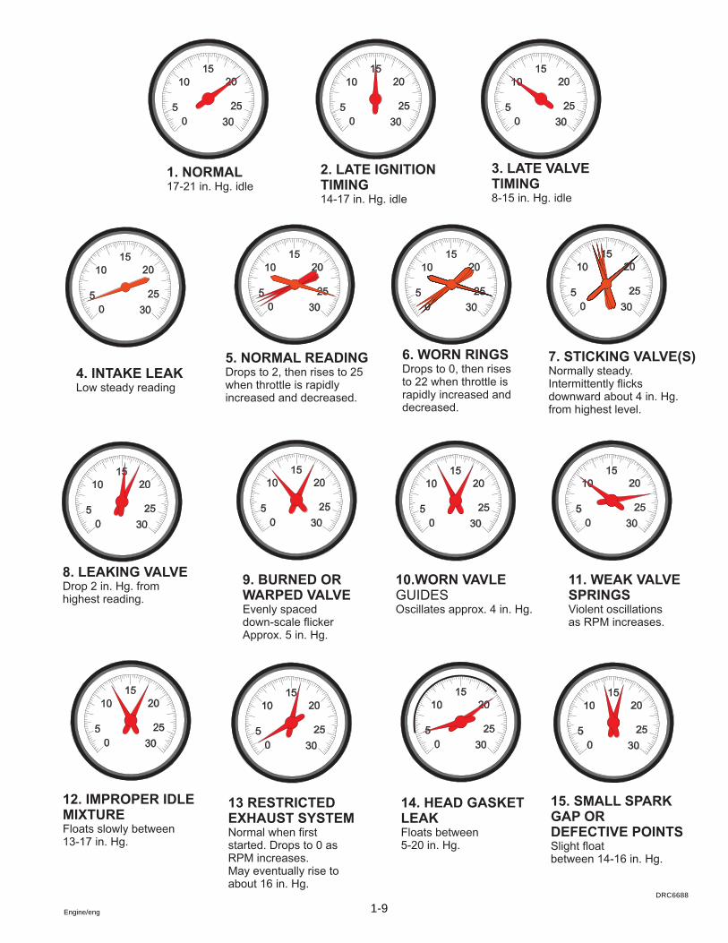
9. See chart on the following page for more information.
1-9Engine/eng
DRC6688
1-10 Engine/eng
Gasoline Requirements
The models covered in this manual are designed for maximum perfor-mance with the use of lead-free gasoline with the following minimumor higher octane specification:
Inside the U.S., (R+M)/2 (AKI) - 89
Outside the U.S., (RON) - 93
4.3 GL, GS, 5.0 GL, and 5.7 GS Models Only - The ignition timing willhave to be retarded if lower octane fuels, with minimum 86 AKI (90RON) octane, are used. Refer to “Timing” in Tune-up Specifications .When ignition timing is retarded, a slight decrease in power can beexpected.
Use of gasoline with lower than 89 AKI (93 RON) octane in 4.3GL, GS, 5.0 GL, and 5.7 GS models, without retarding ignition timingas specified, will result in serious damage to your engine and will voidthe engine warranty.
All Other Models - Lower octane fuels, with minimum 86 AKI (90 RON)octane, can be used. With the use of lower octane fuel, a slight de-crease in power can be expected.
Engine damage resulting from the use of gasoline withoctane lower than 86 AKI (90 RON) is considered misuse of theengine and will void the engine warranty.
Some marinas sell fuel with lead additives. Do not use such fuel as itmay plug the fuel injectors. Premium fuel contains injector cleanersand other additives that protect the fuel system and provide optimumperformance. The use of premium grade fuels in all models isstrongly recommended. To prevent gum formation and corrosion inthe fuel system, use DuraPlusTM Marine Fuel Cleaner in the gasoline.DuraPlusTM Marine Fuel Cleaner is available from your authorizeddealer.
Gasoline is extremely flammable and highly explosive undercertain conditions. Always stop engine and do not smoke or al-low open flames or sparks near the boat when refueling gas tanks.
When filling the gas tank, ground the tank to the source ofgasoline by holding the hose nozzle firmly against the side of thedeck filler plate, or ground it in some other manner. This actionprevents static electricity build-up which could cause sparks andignite fuel vapors.
Gasolines Containing Alcohol
Many gasolines being sold today contain alcohol. Two commonly usedalcohol additives are Ethanol (ethyl alcohol) and Methanol (methyl al-cohol).
Safety Related
1-11Engine/eng
See the boat’s Operators Manual to determine if the boat’s fuel systemis compatible with alcohol blended fuels. If it is, your engine may usegasolines blended with no more than 10% Ethanol (ethyl alcohol) meet-ing the minimum octane specification. Do not use any gasoline whichcontains METHANOL (methyl alcohol).
Continued use of METHANOL (methyl alcohol) fuel will causeserious damage to the fuel system.
If you use gasoline containing alcohol, be aware of the following:
• The engine will operate leaner. This may cause engineproblems such as vapor lock, low speed stalling, or hardstarting.
• Alcohol blended fuels attract and hold moisture. Moisturecan cause fuel tank corrosion. Inspect fuel tanks at leastannually. Replace corroded or leaking fuel tanks.
• Frequently inspect non-metallic parts of fuel system andreplace if excessively stiff, deteriorated or leaking.
Fuel leakage can contribute to a fire and/or explosion.
Crankcase Oil
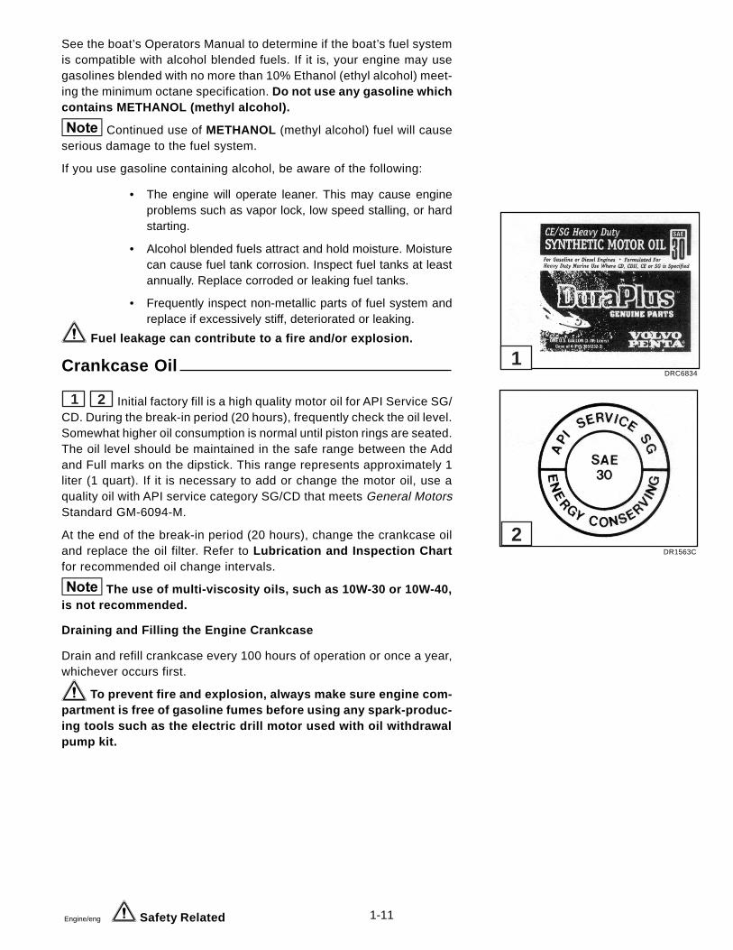
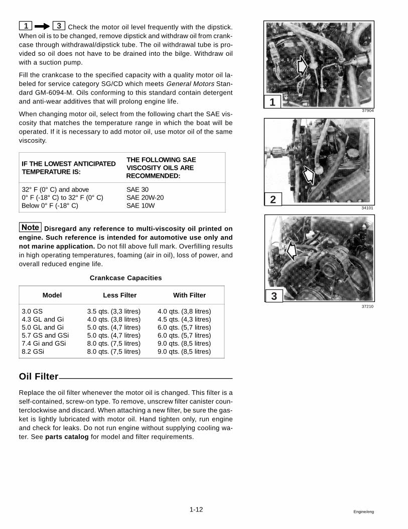
1 2 Initial factory fill is a high quality motor oil for API Service SG/CD. During the break-in period (20 hours), frequently check the oil level.Somewhat higher oil consumption is normal until piston rings are seated.The oil level should be maintained in the safe range between the Addand Full marks on the dipstick. This range represents approximately 1liter (1 quart). If it is necessary to add or change the motor oil, use aquality oil with API service category SG/CD that meets General MotorsStandard GM-6094-M.
At the end of the break-in period (20 hours), change the crankcase oiland replace the oil filter. Refer to Lubrication and Inspection Chartfor recommended oil change intervals.
The use of multi-viscosity oils, such as 10W-30 or 10W-40,is not recommended.
Draining and Filling the Engine Crankcase
Drain and refill crankcase every 100 hours of operation or once a year,whichever occurs first.
To prevent fire and explosion, always make sure engine com-partment is free of gasoline fumes before using any spark-produc-ing tools such as the electric drill motor used with oil withdrawalpump kit.
Safety Related
DRC6834
DR1563C
1
2
1-12 Engine/eng
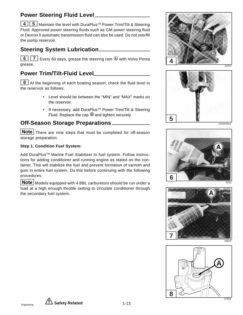
1 3 Check the motor oil level frequently with the dipstick.When oil is to be changed, remove dipstick and withdraw oil from crank-case through withdrawal/dipstick tube. The oil withdrawal tube is pro-vided so oil does not have to be drained into the bilge. Withdraw oilwith a suction pump.
Fill the crankcase to the specified capacity with a quality motor oil la-beled for service category SG/CD which meets General Motors Stan-dard GM-6094-M. Oils conforming to this standard contain detergentand anti-wear additives that will prolong engine life.
When changing motor oil, select from the following chart the SAE vis-cosity that matches the temperature range in which the boat will beoperated. If it is necessary to add motor oil, use motor oil of the sameviscosity.
Disregard any reference to multi-viscosity oil printed onengine. Such reference is intended for automotive use only andnot marine application. Do not fill above full mark. Overfilling resultsin high operating temperatures, foaming (air in oil), loss of power, andoverall reduced engine life.
Crankcase Capacities
Oil Filter
Replace the oil filter whenever the motor oil is changed. This filter is aself-contained, screw-on type. To remove, unscrew filter canister coun-terclockwise and discard. When attaching a new filter, be sure the gas-ket is lightly lubricated with motor oil. Hand tighten only, run engineand check for leaks. Do not run engine without supplying cooling wa-ter. See parts catalog for model and filter requirements.
37904
34101
37210
1
2
3
IF THE LOWEST ANTICIPATEDTEMPERATURE IS:
THE FOLLOWING SAEVISCOSITY OILS ARERECOMMENDED:
32° F (0° C) and above0° F (-18° C) to 32° F (0° C)Below 0° F (-18° C)
SAE 30SAE 20W-20SAE 10W
Model Less Filter With Filter
3.0 GS4.3 GL and Gi5.0 GL and Gi5.7 GS and GSi7.4 Gi and GSi8.2 GSi
3.5 qts. (3,3 litres)4.0 qts. (3,8 litres)5.0 qts. (4,7 litres)5.0 qts. (4,7 litres)8.0 qts. (7,5 litres)8.0 qts. (7,5 litres)
4.0 qts. (3,8 litres)4.5 qts. (4,3 litres)6.0 qts. (5,7 litres)6.0 qts. (5,7 litres)9.0 qts. (8,5 litres)9.0 qts. (8,5 litres)
1-13Engine/eng Safety Related
Power Steering Fluid Level
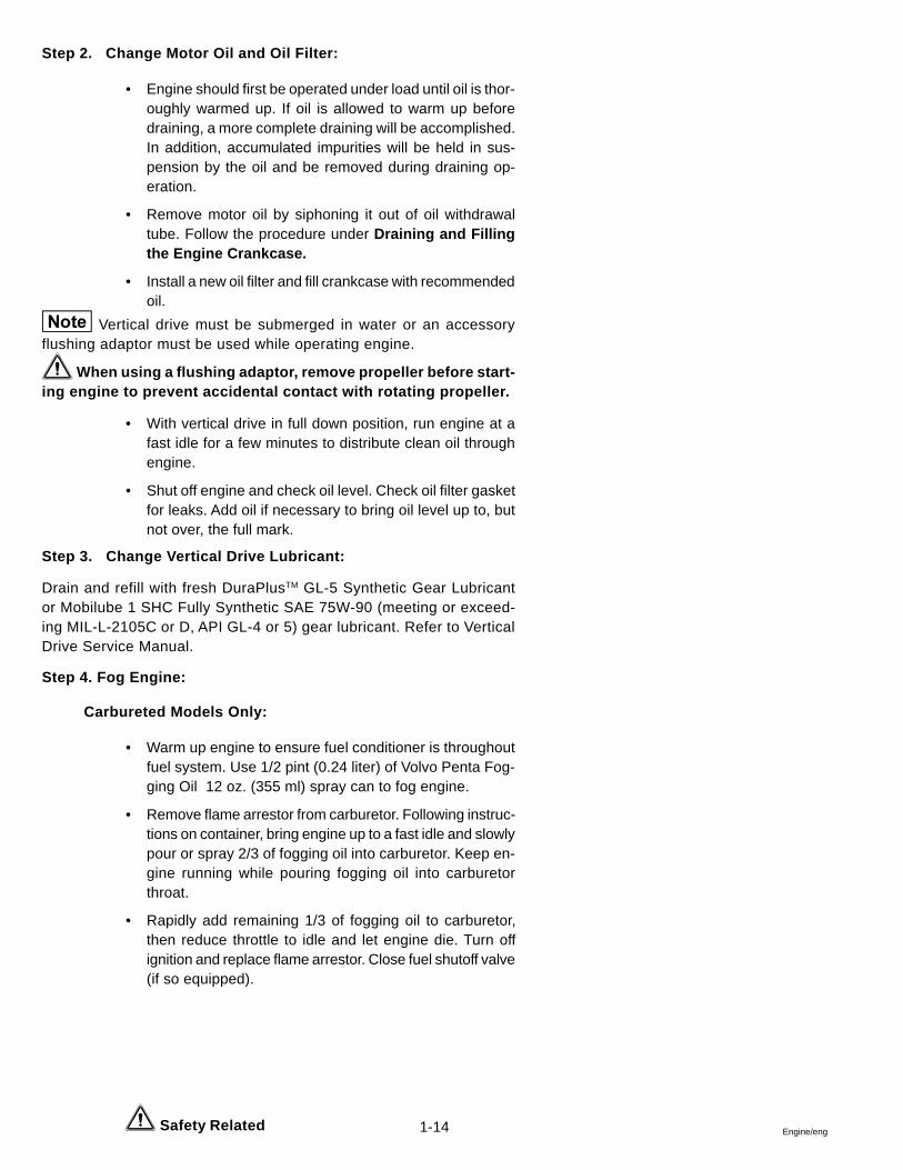
4 5 Maintain the level with DuraPlusTM Power Trim/Tilt & SteeringFluid. Approved power steering fluids such as GM power steering fluidor Dexron II automatic transmission fluid can also be used. Do not overfillthe pump reservoir.
Steering System Lubrication
6 7 Every 60 days, grease the steering ram A with Volvo Pentagrease.
Power Trim/Tilt-Fluid Level
8 At the beginning of each boating season, check the fluid level inthe reservoir as follows:
• Level should be between the “MIN” and “MAX” marks onthe reservoir.
• If necessary, add DuraPlusTM Power Trim/Tilt & SteeringFluid. Replace the cap B and tighten securely.
Off-Season Storage Preparations
There are nine steps that must be completed for off-seasonstorage preparation.
Step 1. Condition Fuel System:
Add DuraPlusTM Marine Fuel Stabilizer to fuel system. Follow instruc-tions for adding conditioner and running engine as stated on the con-tainer. This will stabilize the fuel and prevent formation of varnish andgum in entire fuel system. Do this before continuing with the followingprocedures.
Models equipped with 4 BBL carburetors should be run under aload at a high enough throttle setting to circulate conditioner throughthe secondary fuel system.
24074
COA6781A
3253
29819
47564
A
8
7
6
5
4
1-14 Engine/eng Safety Related
Step 2. Change Motor Oil and Oil Filter:
• Engine should first be operated under load until oil is thor-oughly warmed up. If oil is allowed to warm up beforedraining, a more complete draining will be accomplished.In addition, accumulated impurities will be held in sus-pension by the oil and be removed during draining op-eration.
• Remove motor oil by siphoning it out of oil withdrawaltube. Follow the procedure under Draining and Fillingthe Engine Crankcase.
• Install a new oil filter and fill crankcase with recommendedoil.
Vertical drive must be submerged in water or an accessoryflushing adaptor must be used while operating engine.
When using a flushing adaptor, remove propeller before start-ing engine to prevent accidental contact with rotating propeller.
• With vertical drive in full down position, run engine at afast idle for a few minutes to distribute clean oil throughengine.
• Shut off engine and check oil level. Check oil filter gasketfor leaks. Add oil if necessary to bring oil level up to, butnot over, the full mark.
Step 3. Change Vertical Drive Lubricant:
Drain and refill with fresh DuraPlusTM GL-5 Synthetic Gear Lubricantor Mobilube 1 SHC Fully Synthetic SAE 75W-90 (meeting or exceed-ing MIL-L-2105C or D, API GL-4 or 5) gear lubricant. Refer to VerticalDrive Service Manual.
Step 4. Fog Engine:
Carbureted Models Only:
• Warm up engine to ensure fuel conditioner is throughoutfuel system. Use 1/2 pint (0.24 liter) of Volvo Penta Fog-ging Oil 12 oz. (355 ml) spray can to fog engine.
• Remove flame arrestor from carburetor. Following instruc-tions on container, bring engine up to a fast idle and slowlypour or spray 2/3 of fogging oil into carburetor. Keep en-gine running while pouring fogging oil into carburetorthroat.
• Rapidly add remaining 1/3 of fogging oil to carburetor,then reduce throttle to idle and let engine die. Turn offignition and replace flame arrestor. Close fuel shutoff valve(if so equipped).
1-15Engine/eng
Fuel Injected Models Only:
Prepare an engine “storage mixture” in an outboard V6 six gallon fueltank. It must consist of 5 gallons fuel; 4 pints (64 oz.) Volvo Penta Fog-ging Oil; and 1/3 cup (2.5 oz.) DuraPlusTM Marine Fuel Stabilizer. Mixthese ingredients thoroughly.
• Disconnect boat fuel line at engine fuel pump. Run engineon the “storage mixture” for approximately 5 minutes at1500 RPM. This will ensure that all fuel system and inter-nal engine components are thoroughly protected. Shut offengine before the “storage mixture” is used up.
Do not run engine out of fuel. The electric fuel pumps will bedamaged.
Step 5. Drain Cooling System:
When draining engine, raise or lower bow of boat to position engine in ahorizontal plane. This will provide for complete drainage of block andmanifolds. If bow of boat is higher or lower than stern, some water maybe trapped in block or manifolds. Improper or incomplete drainingmay result in freeze damage to the engine, manifolds, vertical driveor other components. Freeze damage is not covered under the war-ranty.
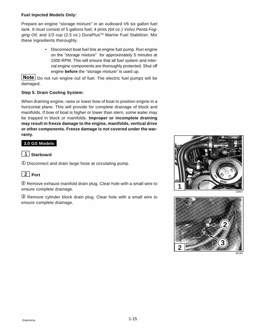
3.0 GS Models
1 Starboard
1 Disconnect and drain large hose at circulating pump.
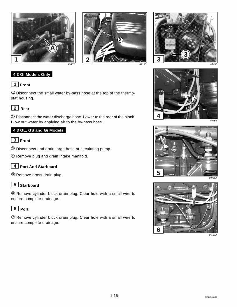
2 Port
2 Remove exhaust manifold drain plug. Clear hole with a small wire toensure complete drainage.
3 Remove cylinder block drain plug. Clear hole with a small wire toensure complete drainage.
23907
46195
1
2
1-16 Engine/eng
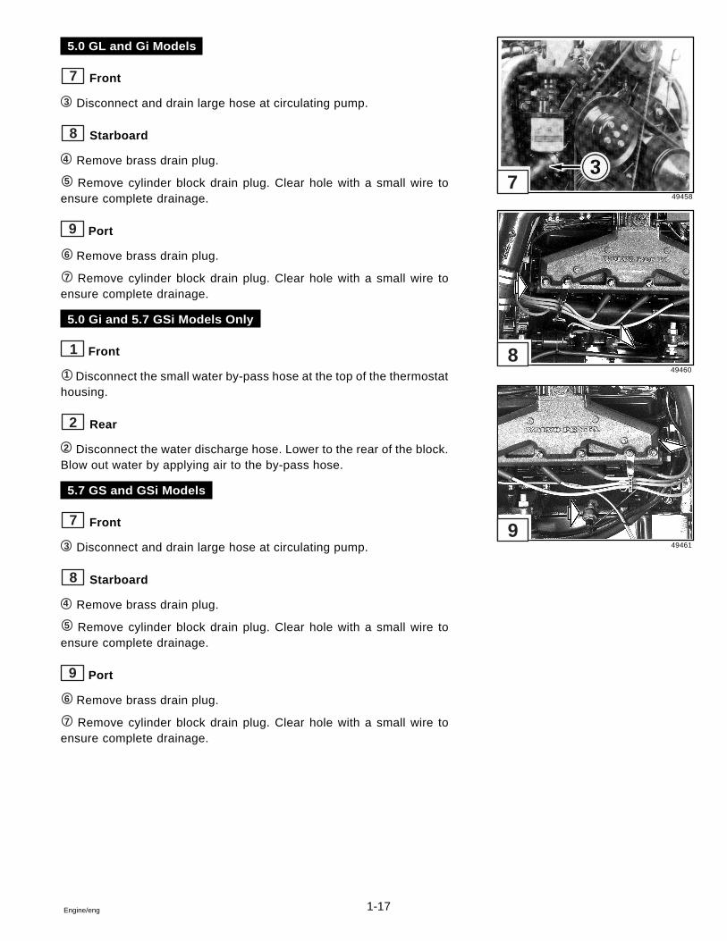
4.3 Gi Models Only
1 Front
1 Disconnect the small water by-pass hose at the top of the thermo-stat housing.
2 Rear
2 Disconnect the water discharge hose. Lower to the rear of the block.Blow out water by applying air to the by-pass hose.
4.3 GL, GS and Gi Models
3 Front
3 Disconnect and drain large hose at circulating pump.
4 Remove plug and drain intake manifold.
4 Port And Starboard
5 Remove brass drain plug.
5 Starboard
6 Remove cylinder block drain plug. Clear hole with a small wire toensure complete drainage.
6 Port
7 Remove cylinder block drain plug. Clear hole with a small wire toensure complete drainage.
49457 44195 49458
49459
34091A
34102A
6
5
4
31 2
1-17Engine/eng
5.0 GL and Gi Models
7 Front
3 Disconnect and drain large hose at circulating pump.
8 Starboard
4 Remove brass drain plug.
5 Remove cylinder block drain plug. Clear hole with a small wire toensure complete drainage.
9 Port
6 Remove brass drain plug.
7 Remove cylinder block drain plug. Clear hole with a small wire toensure complete drainage.
5.0 Gi and 5.7 GSi Models Only
1 Front
1 Disconnect the small water by-pass hose at the top of the thermostathousing.
2 Rear
2 Disconnect the water discharge hose. Lower to the rear of the block.Blow out water by applying air to the by-pass hose.
5.7 GS and GSi Models
7 Front
3 Disconnect and drain large hose at circulating pump.
8 Starboard
4 Remove brass drain plug.
5 Remove cylinder block drain plug. Clear hole with a small wire toensure complete drainage.
9 Port
6 Remove brass drain plug.
7 Remove cylinder block drain plug. Clear hole with a small wire toensure complete drainage.
49458
49460
49461
7
8
9
1-18 Engine/eng
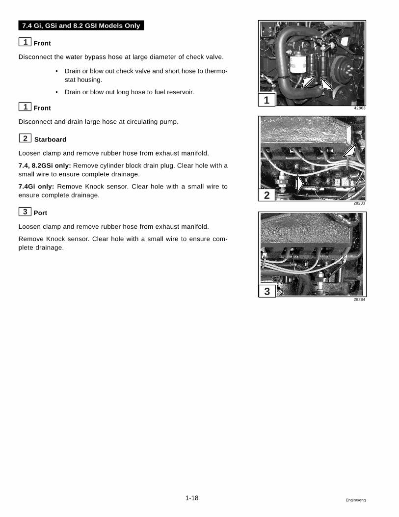
7.4 Gi, GSi and 8.2 GSI Models Only
1 Front
Disconnect the water bypass hose at large diameter of check valve.
• Drain or blow out check valve and short hose to thermo-stat housing.
• Drain or blow out long hose to fuel reservoir.
1 Front
Disconnect and drain large hose at circulating pump.
2 Starboard
Loosen clamp and remove rubber hose from exhaust manifold.
7.4, 8.2GSi only: Remove cylinder block drain plug. Clear hole with asmall wire to ensure complete drainage.
7.4Gi only: Remove Knock sensor. Clear hole with a small wire toensure complete drainage.
3 Port
Loosen clamp and remove rubber hose from exhaust manifold.
Remove Knock sensor. Clear hole with a small wire to ensure com-plete drainage.
42863
28283
28284
2
1
3
1-19Engine/eng
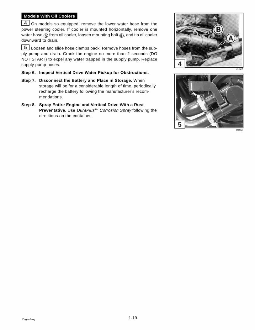
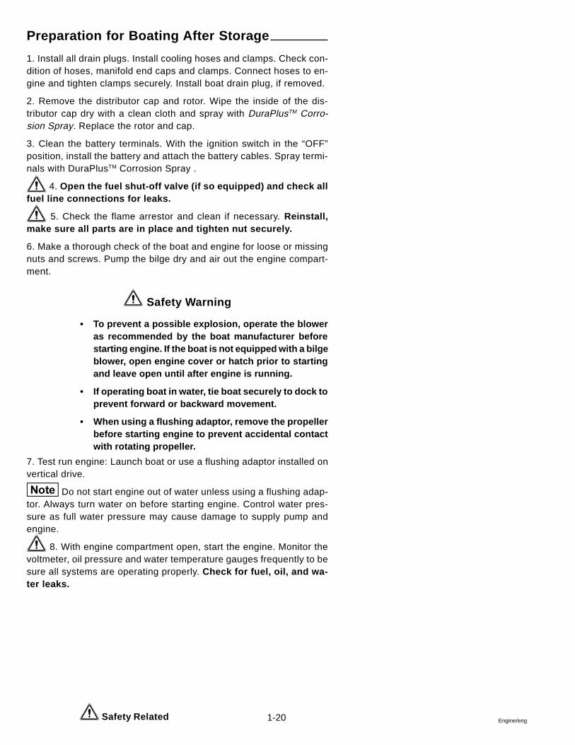
Models With Oil Coolers
On models so equipped, remove the lower water hose from thepower steering cooler. If cooler is mounted horizontally, remove onewater hose A from oil cooler, loosen mounting bolt B , and tip oil coolerdownward to drain.
Loosen and slide hose clamps back. Remove hoses from the sup-ply pump and drain. Crank the engine no more than 2 seconds (DONOT START) to expel any water trapped in the supply pump. Replacesupply pump hoses.
Step 6. Inspect Vertical Drive Water Pickup for Obstructions.
Step 7. Disconnect the Battery and Place in Storage. Whenstorage will be for a considerable length of time, periodicallyrecharge the battery following the manufacturer’s recom-mendations.
Step 8. Spray Entire Engine and Vertical Drive With a RustPreventative. Use DuraPlusTM Corrosion Spray following thedirections on the container.
21122
49462
4
5
4
5
1-20 Engine/eng
Preparation for Boating After Storage
1. Install all drain plugs. Install cooling hoses and clamps. Check con-dition of hoses, manifold end caps and clamps. Connect hoses to en-gine and tighten clamps securely. Install boat drain plug, if removed.
2. Remove the distributor cap and rotor. Wipe the inside of the dis-tributor cap dry with a clean cloth and spray with DuraPlusTM Corro-sion Spray. Replace the rotor and cap.
3. Clean the battery terminals. With the ignition switch in the “OFF”position, install the battery and attach the battery cables. Spray termi-nals with DuraPlusTM Corrosion Spray .
4. Open the fuel shut-off valve (if so equipped) and check allfuel line connections for leaks.
5. Check the flame arrestor and clean if necessary. Reinstall,make sure all parts are in place and tighten nut securely.
6. Make a thorough check of the boat and engine for loose or missingnuts and screws. Pump the bilge dry and air out the engine compart-ment.
Safety Warning
• To prevent a possible explosion, operate the bloweras recommended by the boat manufacturer beforestarting engine. If the boat is not equipped with a bilgeblower, open engine cover or hatch prior to startingand leave open until after engine is running.
• If operating boat in water, tie boat securely to dock toprevent forward or backward movement.
• When using a flushing adaptor, remove the propellerbefore starting engine to prevent accidental contactwith rotating propeller.
7. Test run engine: Launch boat or use a flushing adaptor installed onvertical drive.
Do not start engine out of water unless using a flushing adap-tor. Always turn water on before starting engine. Control water pres-sure as full water pressure may cause damage to supply pump andengine.
8. With engine compartment open, start the engine. Monitor thevoltmeter, oil pressure and water temperature gauges frequently to besure all systems are operating properly. Check for fuel, oil, and wa-ter leaks.
Safety Related
1-21Engine/eng
Engine Break-inAll engines have been run for a short period of time as a final test at thefactory. You must follow the Engine Break-In procedure during the first20 hours of operation to ensure maximum performance and longestengine life.
To ensure proper lubrication during the break-in period, do notremove factory break-in oil until after the 20-hour break-in is completed.
First Two Hours
For the first five to ten minutes of operation, operate engine at a fastidle (above 1500 RPM). After engine has reached operating tempera-ture, momentarily reduce engine speed, then increase engine speed,to assist break-in of rings and bearings.
During the remaining first two hours of operation, accelerate to bringboat onto plane quickly and bring throttle back to maintain a planingattitude. During this period, vary the engine speed frequently by accel-erating to approximately three-fourths throttle for two to three minutes,then back to minimum planing speed. Maintain planing attitude to avoidexcessive engine load.
DO NOT RUN ENGINE AT A CONSTANT RPM FOR PROLONGEDPERIODS OF TIME DURING THE BREAK-IN PERIOD.
Next Eight Hours
During next eight hours, continue to operate at approximately three-fourths throttle or less (minimum planing speed). Occasionally reducethrottle to idle speed for a cooling period. During this eight hours ofoperation it is permissible to operate at full throttle for periods of lessthan two minutes.
DO NOT RUN ENGINE AT A CONSTANT RPM FOR PROLONGED PE-RIODS OF TIME DURING THE BREAK-IN PERIOD.
Final Ten Hours
During the final ten hours of break-in, after warming engine to operat-ing temperature, it is permissible to operate at full throttle for five to tenminutes at a time. Momentarily reduce then increase engine speed toassist break-in of rings and bearings. Occasionally reduce engine speedto idle to provide cooling periods.
1-22 Engine/eng
DO NOT RUN ENGINE AT A CONSTANT RPM FOR PROLONGEDPERIODS OF TIME DURING THE BREAK-IN PERIOD.
During break-in period, be particularly observant during initial runningof engine, as follows:
1. Check crankcase oil level frequently. Maintain oil level in safe range,between “add” and “full” marks on dipstick.
If you have a problem getting a good oil level reading on dip-stick, rotate dipstick 180 ° in tube.
2. Watch oil pressure gauge. If indicator fluctuates whenever boat at-titude (i.e. turning, climbing on plane, etc.) is changed, it may be theoil pickup screen is not covered with oil. Check crankcase dipstick,and add oil to crankcase if required. DO NOT OVERFILL. If oil level iscorrect and condition still exists, check for possible gauge or oil pumpmalfunction.
Oil pressure will rise as RPM increases, and fall as RPM de-creases. In addition, cold oil will generally show higher oil pressure forany specific RPM than hot oil. Both of these conditions reflect normalengine operation.
3. Watch engine temperature indicator to be sure there is proper watercirculation.
Failure to follow the break-in procedure will void the enginewarranty.
At end of break-in period (20 hours), remove motor oil and replace oilfilter. Fill crankcase with recommended 4-cycle motor oil.
Operation After Break-in
After break-in, the engine can be operated at any RPM from idle to fullthrottle. However, cruising at 3600 RPM or less saves fuel, reducesnoise, and prolongs engine life.
When starting a cold engine, always allow engine to warm up gradu-ally. Never run engine at full throttle until engine is thoroughly warmedup. Be sure to check oil level frequently during the first 50 hours ofoperation, since oil consumption will be high until piston rings are prop-erly seated.
1-23Engine/eng
Submerged Engine
Remove engine from water as quickly as possible.
It is imperative that your dealer remove all water from the engine andimmediately relubricate all internal parts. All electrical devices must alsobe dried and inspected for water damage. Delay in completing theseactions may allow extensive engine damage.
Frequently check engine compartment for gasoline fumes and exces-sive water accumulation; water depth in bilge should be kept well belowflywheel housing.
20-Hour Check
1. Change engine oil and oil filter.
2. Check power trim/tilt reservoir for proper fluid level.
3. 3.0 GS Models Only: Clean and inspect the ceramic filter locatedunder the fuel pump.
4. All Models Except 3.0 GS: Change fuel filter/water separator.
5. Check flame arrestor for proper mounting.
6. Start engine and check complete fuel system for leaks.
7. Lubricate steering cable ram with Volvo Penta grease. Checkpower steering pump reservoir for correct fluid level on modelsequipped with power steering. Failure to properly lubricate thesteering system could lead to loss of steering control.
8. Check shift system for proper adjustment and operation.
9. Inspect exhaust system. Tighten all hose clamps, and checkfor leaks.
10. Check tension on all drive belts.
11. Check all engine mount screws for tightness.
Safety Related
1-24 Engine/eng
5
12. Carbureted Models Only: Check and adjust carburetor for cor-rect idle mixture and RPM.
13. Check for any deficiencies, malfunctions, signs of abuse, etc. Cor-rection of any problems at this time will prevent the worsening of aminor problem and help ensure a trouble-free boating season.
14. Check oil level in vertical drive and add as necessary withDuraPlusTM GL-5 Synthetic Gear Lubricant or Mobilube 1 SHC FullySynthetic SAE 75W-90 (meeting or exceeding MIL-L-2105C or D, APIGL-4 or 5) gear lubricant.
14. Make sure engine can achieve maximum rated RPM. See enginespecifications.
Belt Tension
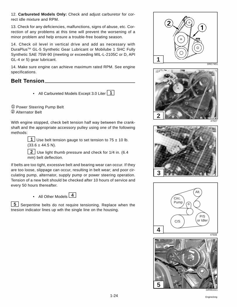
• All Carbureted Models Except 3.0 Liter 1
1 Power Steering Pump Belt2 Alternator Belt
With engine stopped, check belt tension half way between the crank-shaft and the appropriate accessory pulley using one of the followingmethods:
1 Use belt tension gauge to set tension to 75 ± 10 lb.(33.6 ± 44.5 N).
2 Use light thumb pressure and check for 1/4 in. (6.4mm) belt deflection.
If belts are too tight, excessive belt and bearing wear can occur. If theyare too loose, slippage can occur, resulting in belt wear; and poor cir-culating pump, alternator, supply pump or power steering operation.Tension of a new belt should be checked after 10 hours of service andevery 50 hours thereafter.
• All Other Models 4
5 Serpentine belts do not require tensioning. Replace when thetnesion indicator lines up wth the single line on the housing.
DRC7451
47507
47508
1
2
3
4
Alt.
P/Sor Idler
Circ.Pump
C/S
GR991021
1-25Engine/eng
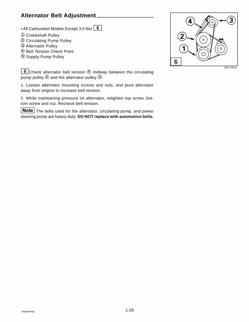
Alternator Belt Adjustment
• All Carbureted Models Except 3.0 liter 61 Crankshaft Pulley2 Circulating Pump Pulley3 Alternator Pulley4 Belt Tension Check Point5 Supply Pump Pulley
6 Check alternator belt tension 4 midway between the circulatingpump pulley 2 and the alternator pulley 3 .
1. Loosen alternator mounting screws and nuts, and pivot alternatoraway from engine to increase belt tension.
2. While maintaining pressure on alternator, retighten top screw, bot-tom screw and nut. Recheck belt tension.
The belts used for the alternator, circulating pump, and powersteering pump are heavy-duty. DO NOT replace with automotive belts.
DRC7451A
6
1-26 Engine/eng
Power Steering Pump Belt Adjustment
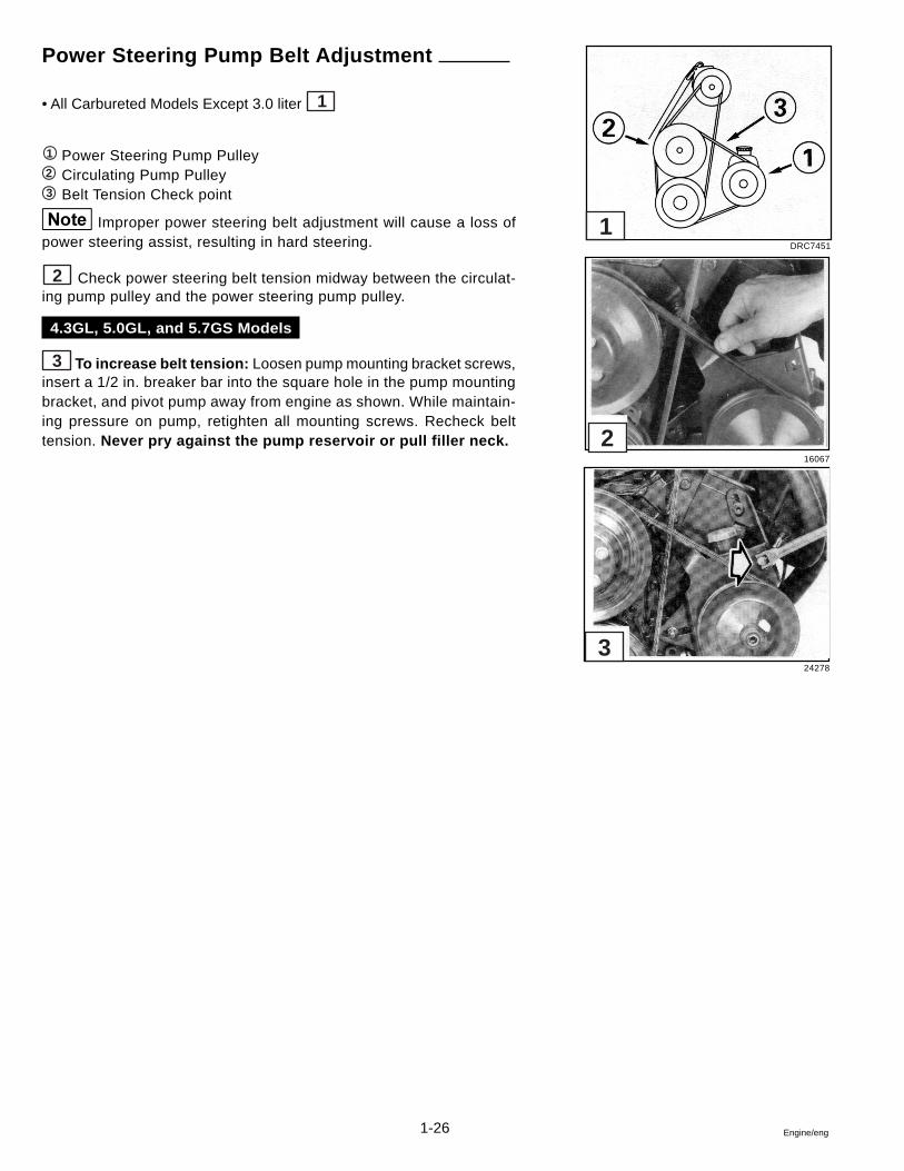
• All Carbureted Models Except 3.0 liter 1
1 Power Steering Pump Pulley2 Circulating Pump Pulley3 Belt Tension Check point
Improper power steering belt adjustment will cause a loss ofpower steering assist, resulting in hard steering.
2 Check power steering belt tension midway between the circulat-ing pump pulley and the power steering pump pulley.
4.3GL, 5.0GL, and 5.7GS Models
3 To increase belt tension: Loosen pump mounting bracket screws,insert a 1/2 in. breaker bar into the square hole in the pump mountingbracket, and pivot pump away from engine as shown. While maintain-ing pressure on pump, retighten all mounting screws. Recheck belttension. Never pry against the pump reservoir or pull filler neck.
DRC7451
16067
24278
1
2
3
1-27Engine/eng
Positive Closed-Type Ventilation System
A malfunctioning closed crankcase ventilation system may be indicatedby loping or rough engine idle. Do not attempt to compensate for thisidle condition by disconnecting the crank-case ventilation system andmaking carburetor adjustments. The removal of the crankcase venti-lation system from the engine will adversely affect fuel economyand engine ventilation with resultant shortening of engine life. Todetermine whether loping or rough idle condition is caused by a mal-functioning crankcase ventilation system, perform the following tests.
With Engine Idling
1. Remove PCV valve from its mounting, but leave vacuum inlet sideconnected to hose. If the valve is functioning properly and not plugged,a hissing noise will be heard as air passes through valve. A strongvacuum will be felt when a finger is placed over valve inlet. Check forvacuum leaks in hose line and at all connections.
2. Reinstall PCV valve, then remove crankcase air inlet hose at flamearrestor connection. Loosely hold a small piece of stiff paper (such as a3 x 5 memo card or parts tag card) over opening at end of inlet hose.After a minute or so, (to allow crankcase pressure to lower) the piece ofpaper should be sucked against hose opening with a noticeable force.
With Engine Stopped
Remove PCV valve from its mounting and shake it. A metallic clickingnoise should be heard, indicating that valve parts are free, and not stick-ing.
If ventilation system passes these two tests, it can be considered func-tionally OK, and no further service is required. If it fails either test, re-place PCV valve and repeat Engine Idling Test.
If system still does not pass test, clean ventilation system hoses and allpassages to induction system in accordance with established proce-dures.
Servicing PCV Valve
Do not attempt to clean crankcase ventilation regulator valve, itshould be replaced. Clean crankcase ventilation system connection(s)on intake manifold by probing with a flexible wire or bottle brush. Cleanhoses, tubes and associated hardware with a low-volatility, petroleum-base solvent and dry with compressed air.
1-28 Engine/eng
Troubleshooting - System Isolation
The following is to help you isolate a malfunction of one or possibly several systems. After determining which sys-tems are related to the malfunction, refer to the individual system troubleshooting charts to isolate the specific cause.
EngineDoes Not
Run
CrankingSystem
Engine should crank at specified RPM. If not, check for:
1. Discharged or dead battery2. Loose or corroded connections3. Cranking System Troubleshooting Chart in the Electrical/ Ignition/Fuel Service Manual
Must have good spark at spark plugs. If not, check the:
1. Distributor cap and rotor2. Coil and spark plug leads3. Ignition timing4. Automatic spark advance5. Appropriate Ignition Troubleshooting Chart in the Electrical/Ignition/Fuel Service Manual6. EFI Models: refer to GM Diagnostic Manual
EFI Models: refer to GM Diagnostic Manual
Non-EFI Models: Carburetor accelerator pump should squirt fuel intoventuri when throttle is advanced. If not, check the:
1. Fuel tank, valves, and lines2. Fuel pumps and filter3. Carburetor and filter4. Boat Fuel System Troubleshooting Chart5. Carburetor Troubleshooting Chart6. Engine Fuel System Troubleshooting Chart
Check the following:
1. Compression2. Ignition system3. Fuel and carburetor/injector system4. Lubrication system5. Cooling system6. Vertical drive and propeller7. Vertical drive gear ratio and installation8. PCV Valve9. Engine Troubleshooting Guides
IgnitionSystem
FuelSystem
Engine RunsImproperly
1-29Engine/eng
Engine Troubleshooting Guides
EFI Engines Only: Refer to EFI Diagnostic Service Manual.
These guides were written to help you trace the symptoms of the troubleto the source, without having to read through and prove every possibil-ity. Much of the information here will be familiar to well informed me-chanics.
Also, many factors will seem insignificant but when you think of it, usu-ally the toughest problem to troubleshoot is caused by the smallest er-ror. The greatest aid to solving a service problem is information. Startgathering information from the boat operator and write it on his job cardor work ticket. Find out pertinent facts, such as:
• When did this trouble start?• How was the boat loaded?• Did the trouble occur suddenly, or start gradually?
Analyze this information and try to match it to similar situations youhave experienced in the past. Keep in mind the fundamental rules:
1. COMPRESSION - Mixture inducted into cylinder and compressed.
2. SPARK - Proper intensity at the proper time.
3. FUEL - Proper mixture of air and fuel.
These are very old rules, but necessary for the engine to run. Use thesecharts and the service information they refer to. Do not try to remembertolerances, settings, measurements, etc., as they are written in the ser-vice manual. Leave your mind free to analyze the problem.
Following is a list of the troubleshooting guides which may be found onthe pages indicated.
Title ................................................................................................... Page
1. Engine Will Not Crank ................................................................. 1-302. Engine Cranks, But Will Not Start .............................................. 1-303. Hard Starting - Cold Engine ........................................................ 1-314. Hard Starting - Hot Engine.......................................................... 1-315. Engine Runs Rough .................................................................... 1-326. Engine Noises and Vibrations .................................................... 1-327. Engine Overheats ........................................................................ 1-338. Engine Dies Out .......................................................................... 1-349. Engine Won’t Reach Operating RPM ......................................... 1-3410.Defective Engine Lubricating System ........................................ 1-3511. Low Battery Voltage After Short Storage ................................... 1-35
1-30 Engine/eng
Engine Will Not Crank
Starter Circuit - Check:
• Battery condition: weak, dead, sulfated, bad cells
• Battery cables for loose or corroded connections
• Shorted or open ignition switch
• Starter motor and solenoid for shorts, grounds or opencircuits
• Starter assist solenoid/starter relay
• Circuit breakers
• Wiring from battery to ignition switch
• See Electrical/Ignition/Fuel Service Manual
Engine Cranks, But Will Not Start
Ignition Circuit - Check:
• Primary circuit wiring from ignition switch to ignition coil/ignition module
• Secondary circuit wiring from coil to spark plug
• Spark plugs for proper gap, fouling, burned electrodes,cracked or dirty insulator
• See Electrical/Ignition/Fuel Service Manual
• Low battery voltage
Fuel System - Check:
• Quantity and condition of fuel in boat tank
• Operation and flow capacity of boat anti-siphon valve
• Fuel tank vent is unrestricted
• Fuel tank pick-up screen is clean
• Correct diameter/unrestricted boat fuel lines
• Fuel shutoff and multiple tank valves are open and oper-ating properly
• Fuel pump vent hose for signs of fuel or oil that wouldindicate a fuel pump failure.
• Fuel pump/relay/circuit breaker operation
• External fuel filter canister and carburetor filter
• Carburetor accelerator pump
• See Electrical/Ignition/Fuel System Service Manual
Cylinder Compression - Check
• Conduct test following procedure in this section, and com-pare readings to Compression Limit Chart
1-31Engine/eng
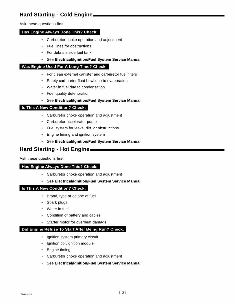
Hard Starting - Cold Engine
Ask these questions first:
Has Engine Always Done This? Check:
• Carburetor choke operation and adjustment
• Fuel lines for obstructions
• For debris inside fuel tank
• See Electrical/Ignition/Fuel System Service Manual
Was Engine Used For A Long Time? Check:
• For clean external canister and carburetor fuel filters
• Empty carburetor float bowl due to evaporation
• Water in fuel due to condensation
• Fuel quality deterioration
• See Electrical/Ignition/Fuel System Service Manual
Is This A New Condition? Check:
• Carburetor choke operation and adjustment
• Carburetor accelerator pump
• Fuel system for leaks, dirt, or obstructions
• Engine timing and ignition system
• See Electrical/Ignition/Fuel System Service Manual
Hard Starting - Hot Engine
Ask these questions first:
Has Engine Always Done This? Check:
• Carburetor choke operation and adjustment
• See Electrical/Ignition/Fuel System Service Manual
Is This A New Condition? Check:
• Brand, type or octane of fuel
• Spark plugs
• Water in fuel
• Condition of battery and cables
• Starter motor for overheat damage
Did Engine Refuse To Start After Being Run? Check:
• Ignition system primary circuit
• Ignition coil/ignition module
• Engine timing
• Carburetor choke operation and adjustment
• See Electrical/Ignition/Fuel System Service Manual
1-32 Engine/eng
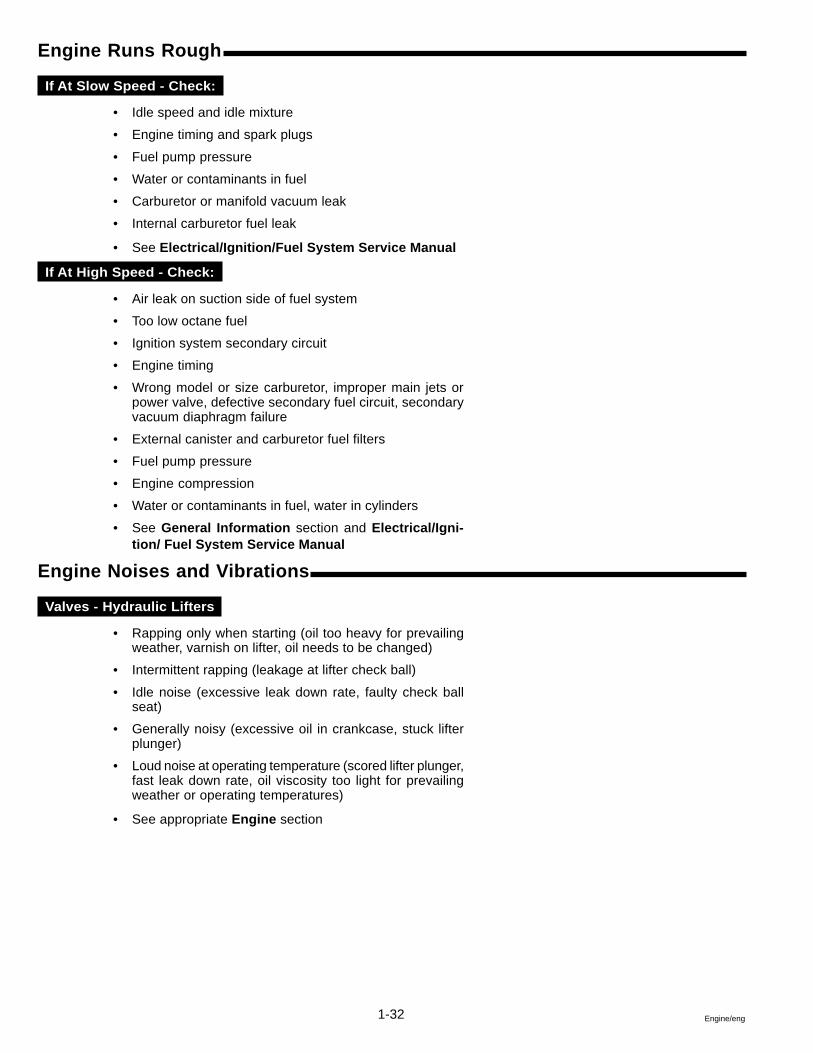
Engine Runs Rough
If At Slow Speed - Check:
• Idle speed and idle mixture
• Engine timing and spark plugs
• Fuel pump pressure
• Water or contaminants in fuel
• Carburetor or manifold vacuum leak
• Internal carburetor fuel leak
• See Electrical/Ignition/Fuel System Service Manual
If At High Speed - Check:
• Air leak on suction side of fuel system
• Too low octane fuel
• Ignition system secondary circuit
• Engine timing
• Wrong model or size carburetor, improper main jets orpower valve, defective secondary fuel circuit, secondaryvacuum diaphragm failure
• External canister and carburetor fuel filters
• Fuel pump pressure
• Engine compression
• Water or contaminants in fuel, water in cylinders
• See General Information section and Electrical/Igni-tion/ Fuel System Service Manual
Engine Noises and Vibrations
Valves - Hydraulic Lifters
• Rapping only when starting (oil too heavy for prevailingweather, varnish on lifter, oil needs to be changed)
• Intermittent rapping (leakage at lifter check ball)
• Idle noise (excessive leak down rate, faulty check ballseat)
• Generally noisy (excessive oil in crankcase, stuck lifterplunger)
• Loud noise at operating temperature (scored lifter plunger,fast leak down rate, oil viscosity too light for prevailingweather or operating temperatures)
• See appropriate Engine section
1-33Engine/eng
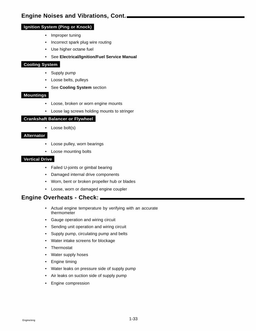
Engine Noises and Vibrations, Cont.
Ignition System (Ping or Knock)
• Improper tuning
• Incorrect spark plug wire routing
• Use higher octane fuel
• See Electrical/Ignition/Fuel Service Manual
Cooling System
• Supply pump
• Loose belts, pulleys
• See Cooling System section
Mountings
• Loose, broken or worn engine mounts
• Loose lag screws holding mounts to stringer
Crankshaft Balancer or Flywheel
• Loose bolt(s)
Alternator
• Loose pulley, worn bearings
• Loose mounting bolts
Vertical Drive
• Failed U-joints or gimbal bearing
• Damaged internal drive components
• Worn, bent or broken propeller hub or blades
• Loose, worn or damaged engine coupler
Engine Overheats - Check:
• Actual engine temperature by verifying with an accuratethermometer
• Gauge operation and wiring circuit
• Sending unit operation and wiring circuit
• Supply pump, circulating pump and belts
• Water intake screens for blockage
• Thermostat
• Water supply hoses
• Engine timing
• Water leaks on pressure side of supply pump
• Air leaks on suction side of supply pump
• Engine compression
1-34 Engine/eng
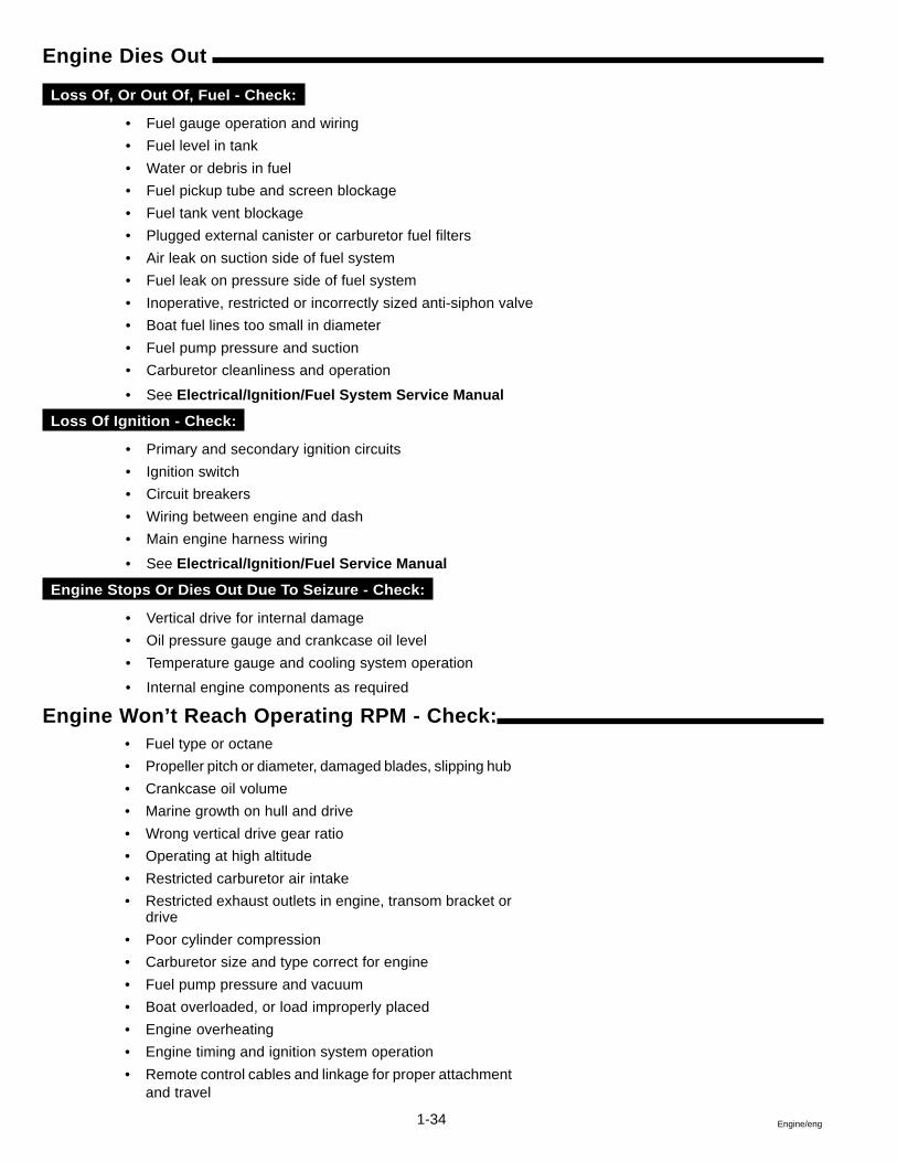
Engine Dies Out
Loss Of, Or Out Of, Fuel - Check:
• Fuel gauge operation and wiring
• Fuel level in tank
• Water or debris in fuel
• Fuel pickup tube and screen blockage
• Fuel tank vent blockage
• Plugged external canister or carburetor fuel filters
• Air leak on suction side of fuel system
• Fuel leak on pressure side of fuel system
• Inoperative, restricted or incorrectly sized anti-siphon valve
• Boat fuel lines too small in diameter
• Fuel pump pressure and suction
• Carburetor cleanliness and operation
• See Electrical/Ignition/Fuel System Service Manual
Loss Of Ignition - Check:
• Primary and secondary ignition circuits
• Ignition switch
• Circuit breakers
• Wiring between engine and dash
• Main engine harness wiring
• See Electrical/Ignition/Fuel Service Manual
Engine Stops Or Dies Out Due To Seizure - Check:
• Vertical drive for internal damage
• Oil pressure gauge and crankcase oil level
• Temperature gauge and cooling system operation
• Internal engine components as required
Engine Won’t Reach Operating RPM - Check:• Fuel type or octane
• Propeller pitch or diameter, damaged blades, slipping hub
• Crankcase oil volume
• Marine growth on hull and drive
• Wrong vertical drive gear ratio
• Operating at high altitude
• Restricted carburetor air intake
• Restricted exhaust outlets in engine, transom bracket ordrive
• Poor cylinder compression
• Carburetor size and type correct for engine
• Fuel pump pressure and vacuum
• Boat overloaded, or load improperly placed
• Engine overheating
• Engine timing and ignition system operation
• Remote control cables and linkage for proper attachmentand travel
1-35Engine/eng
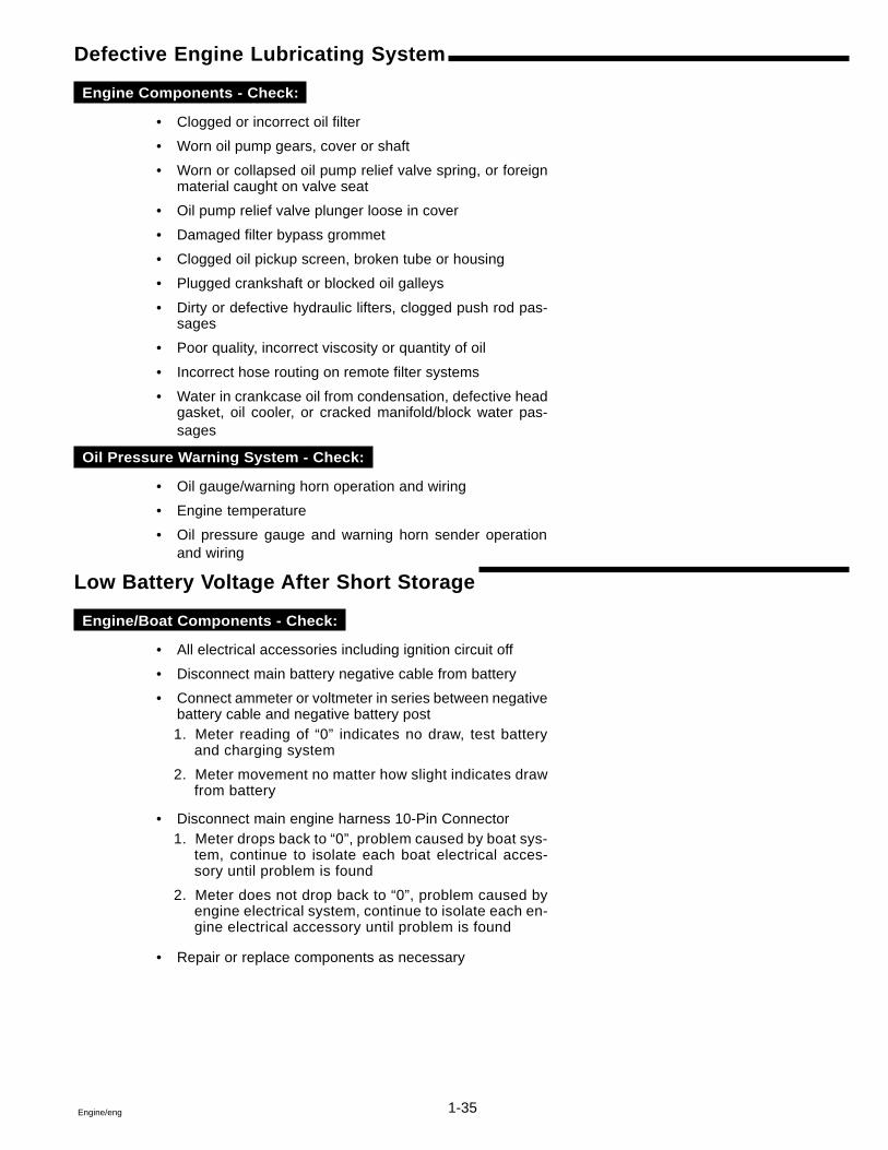
Defective Engine Lubricating System
Engine Components - Check:
• Clogged or incorrect oil filter
• Worn oil pump gears, cover or shaft
• Worn or collapsed oil pump relief valve spring, or foreignmaterial caught on valve seat
• Oil pump relief valve plunger loose in cover
• Damaged filter bypass grommet
• Clogged oil pickup screen, broken tube or housing
• Plugged crankshaft or blocked oil galleys
• Dirty or defective hydraulic lifters, clogged push rod pas-sages
• Poor quality, incorrect viscosity or quantity of oil
• Incorrect hose routing on remote filter systems
• Water in crankcase oil from condensation, defective headgasket, oil cooler, or cracked manifold/block water pas-sages
Oil Pressure Warning System - Check:
• Oil gauge/warning horn operation and wiring
• Engine temperature
• Oil pressure gauge and warning horn sender operationand wiring
Low Battery Voltage After Short Storage
Engine/Boat Components - Check:
• All electrical accessories including ignition circuit off
• Disconnect main battery negative cable from battery
• Connect ammeter or voltmeter in series between negativebattery cable and negative battery post1. Meter reading of “0” indicates no draw, test battery
and charging system
2. Meter movement no matter how slight indicates drawfrom battery
• Disconnect main engine harness 10-Pin Connector1. Meter drops back to “0”, problem caused by boat sys-
tem, continue to isolate each boat electrical acces-sory until problem is found
2. Meter does not drop back to “0”, problem caused byengine electrical system, continue to isolate each en-gine electrical accessory until problem is found
• Repair or replace components as necessary
1-36 Engine/eng
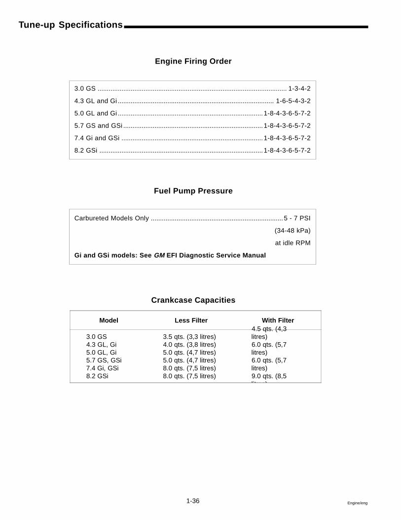
Tune-up Specifications
Engine Firing Order
3.0 GS ....................................................................................................... 1-3-4-2
4.3 GL and Gi ..................................................................................... 1-6-5-4-3-2
5.0 GL and Gi ............................................................................... 1-8-4-3-6-5-7-2
5.7 GS and GSi ............................................................................ 1-8-4-3-6-5-7-2
7.4 Gi and GSi ............................................................................. 1-8-4-3-6-5-7-2
8.2 GSi ......................................................................................... 1-8-4-3-6-5-7-2
Fuel Pump Pressure
Carbureted Models Only ........................................................................5 - 7 PSI
(34-48 kPa)
at idle RPM
Gi and GSi models: See GM EFI Diagnostic Service Manual
Crankcase Capacities
Model Less Filter With Filter
3.0 GS4.3 GL, Gi5.0 GL, Gi5.7 GS, GSi7.4 Gi, GSi8.2 GSi
3.5 qts. (3,3 litres)4.0 qts. (3,8 litres)5.0 qts. (4,7 litres)5.0 qts. (4,7 litres)8.0 qts. (7,5 litres)8.0 qts. (7,5 litres)
4.5 qts. (4,3litres)6.0 qts. (5,7litres)6.0 qts. (5,7litres)9.0 qts. (8,5litres)
1-37Engine/eng
Tune-up Specifications
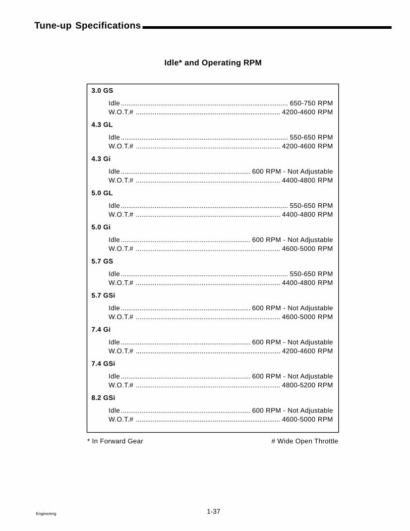
Idle* and Operating RPM
3.0 GS
Idle ......................................................................................... 650-750 RPMW.O.T.# ............................................................................. 4200-4600 RPM
4.3 GL
Idle ......................................................................................... 550-650 RPMW.O.T.# ............................................................................. 4200-4600 RPM
4.3 Gi
Idle ..................................................................... 600 RPM - Not AdjustableW.O.T.# ............................................................................. 4400-4800 RPM
5.0 GL
Idle ......................................................................................... 550-650 RPMW.O.T.# ............................................................................. 4400-4800 RPM
5.0 Gi
Idle ..................................................................... 600 RPM - Not AdjustableW.O.T.# ............................................................................. 4600-5000 RPM
5.7 GS
Idle ......................................................................................... 550-650 RPMW.O.T.# ............................................................................. 4400-4800 RPM
5.7 GSi
Idle ..................................................................... 600 RPM - Not AdjustableW.O.T.# ............................................................................. 4600-5000 RPM
7.4 Gi
Idle ..................................................................... 600 RPM - Not AdjustableW.O.T.# ............................................................................. 4200-4600 RPM
7.4 GSi
Idle ..................................................................... 600 RPM - Not AdjustableW.O.T.# ............................................................................. 4800-5200 RPM
8.2 GSi
Idle ..................................................................... 600 RPM - Not AdjustableW.O.T.# ............................................................................. 4600-5000 RPM
* In Forward Gear # Wide Open Throttle
1-38 Engine/eng
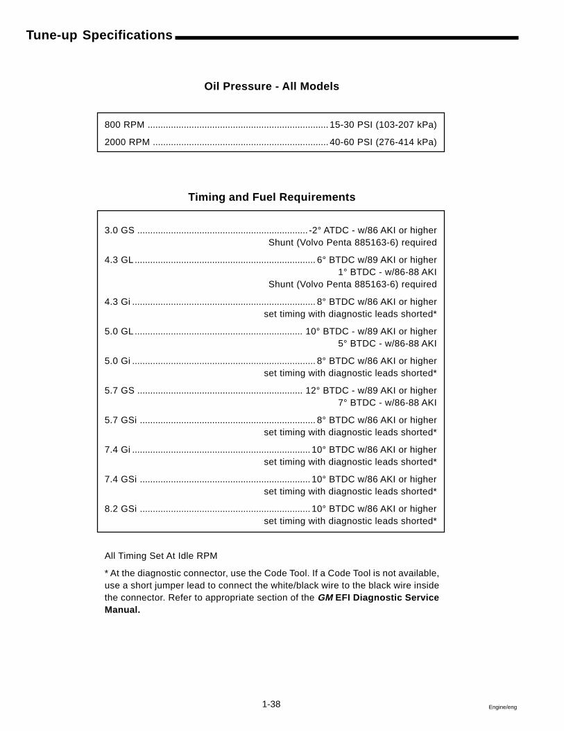
Tune-up Specifications
Oil Pressure - All Models
800 RPM ...................................................................... 15-30 PSI (103-207 kPa)
2000 RPM .................................................................... 40-60 PSI (276-414 kPa)
Timing and Fuel Requirements
3.0 GS .................................................................. -2° ATDC - w/86 AKI or higherShunt (Volvo Penta 885163-6) required
4.3 GL ...................................................................... 6° BTDC w/89 AKI or higher1° BTDC - w/86-88 AKI
Shunt (Volvo Penta 885163-6) required
4.3 Gi ....................................................................... 8° BTDC w/86 AKI or higherset timing with diagnostic leads shorted*
5.0 GL ................................................................. 10° BTDC - w/89 AKI or higher5° BTDC - w/86-88 AKI
5.0 Gi ....................................................................... 8° BTDC w/86 AKI or higherset timing with diagnostic leads shorted*
5.7 GS ................................................................ 12° BTDC - w/89 AKI or higher7° BTDC - w/86-88 AKI
5.7 GSi .................................................................... 8° BTDC w/86 AKI or higherset timing with diagnostic leads shorted*
7.4 Gi ..................................................................... 10° BTDC w/86 AKI or higherset timing with diagnostic leads shorted*
7.4 GSi .................................................................. 10° BTDC w/86 AKI or higherset timing with diagnostic leads shorted*
8.2 GSi .................................................................. 10° BTDC w/86 AKI or higherset timing with diagnostic leads shorted*
All Timing Set At Idle RPM
* At the diagnostic connector, use the Code Tool. If a Code Tool is not available,use a short jumper lead to connect the white/black wire to the black wire insidethe connector. Refer to appropriate section of the GM EFI Diagnostic ServiceManual.
1-39Engine/eng
Tune-up Specifications
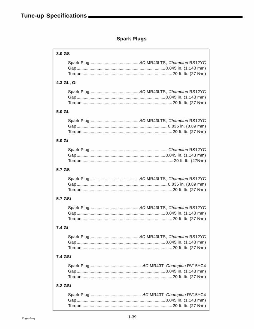
Spark Plugs
3.0 GS
Spark Plug ......................................... AC-MR43LTS, Champion RS12YCGap ............................................................................0.045 in. (1.143 mm)Torque ............................................................................. 20 ft. lb. (27 N•m)
4.3 GL, Gi
Spark Plug ......................................... AC-MR43LTS, Champion RS12YCGap ............................................................................0.045 in. (1.143 mm)Torque ............................................................................. 20 ft. lb. (27 N•m)
5.0 GL
Spark Plug ......................................... AC-MR43LTS, Champion RS12YCGap .............................................................................. 0.035 in. (0.89 mm)Torque ............................................................................. 20 ft. lb. (27 N•m)
5.0 Gi
Spark Plug .................................................................. Champion RS12YCGap ............................................................................0.045 in. (1.143 mm)Torque .............................................................................. 20 ft. lb. (27N•m)
5.7 GS
Spark Plug ......................................... AC-MR43LTS, Champion RS12YCGap .............................................................................. 0.035 in. (0.89 mm)Torque ............................................................................. 20 ft. lb. (27 N•m)
5.7 GSi
Spark Plug ......................................... AC-MR43LTS, Champion RS12YCGap ............................................................................0.045 in. (1.143 mm)Torque ............................................................................. 20 ft. lb. (27 N•m)
7.4 Gi
Spark Plug ......................................... AC-MR43LTS, Champion RS12YCGap ............................................................................0.045 in. (1.143 mm)Torque ............................................................................. 20 ft. lb. (27 N•m)
7.4 GSi
Spark Plug ........................................... AC-MR43T, Champion RV15YC4Gap ............................................................................0.045 in. (1.143 mm)Torque ............................................................................. 20 ft. lb. (27 N•m)
8.2 GSi
Spark Plug ........................................... AC-MR43T, Champion RV15YC4Gap ............................................................................0.045 in. (1.143 mm)Torque ............................................................................. 20 ft. lb. (27 N•m)
1-40 Engine/eng
Pound-inches x 0.11298 = newton-meters N•m
Pound-feet x 1.3558 = newton-meters N•m
Battery Cable Requirements
The battery should be mounted as close to the engine as practical tocut down on battery cable lengths. Follow the recommendations be-low.
• 0-10 Feet 0 Gauge• 10-15 Feet 2/0 Gauge• 15-20 Feet 4/0 Gauge
These specifications do not apply to aluminum battery cables.Volvo Penta does not recommend the use of aluminum battery cables.
To prevent possible explosion or fire, do not substitute au-tomotive parts for the following marine components: starter, al-ternator, distributor and related ignition parts, spark plug leads,solenoids, carburetor (and related parts), fuel pump or fuel filtercanister. These components have been specifically designed notto emit fuel vapors or to cause ignition of fuel vapors in the bilge.
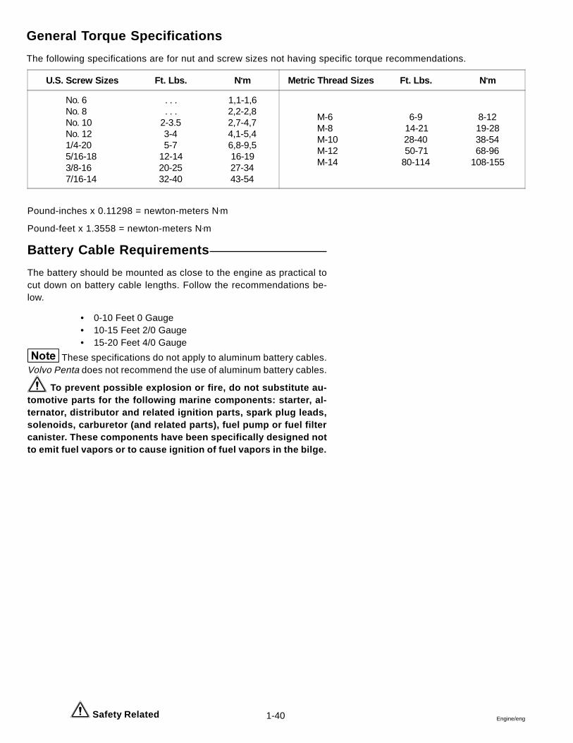
General Torque Specifications
The following specifications are for nut and screw sizes not having specific torque recommendations.
Safety Related
U.S. Screw Sizes Ft. Lbs. N•m Metric Thread Sizes Ft. Lbs. N•m
No. 6 No. 8 No. 10 No. 12 1/4-20 5/16-18 3/8-16 7/16-14
. . .
. . .2-3.53-45-7
12-1420-2532-40
1,1-1,62,2-2,82,7-4,74,1-5,46,8-9,516-1927-3443-54
M-6 M-8 M-10 M-12 M-14
6-914-2128-4050-71
80-114
8-1219-2838-5468-96
108-155
1-41Engine/eng
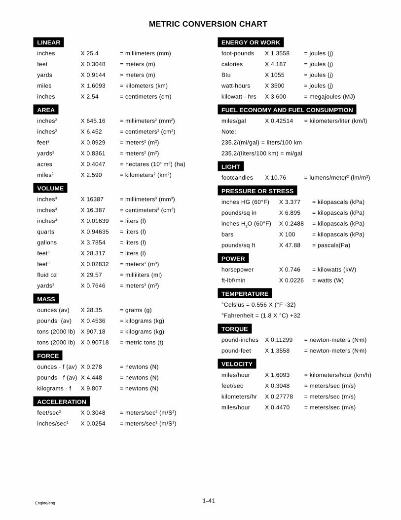
METRIC CONVERSION CHART
LINEAR
inches X 25.4 = millimeters (mm)
feet X 0.3048 = meters (m)
yards X 0.9144 = meters (m)
miles X 1.6093 = kilometers (km)
inches X 2.54 = centimeters (cm)
AREA
inches2 X 645.16 = millimeters2 (mm2)
inches2 X 6.452 = centimeters2 (cm2)
feet2 X 0.0929 = meters2 (m2)
yards2 X 0.8361 = meters2 (m2)
acres X 0.4047 = hectares (104 m2) (ha)
miles2 X 2.590 = kilometers2 (km2)
VOLUME
inches3 X 16387 = millimeters3 (mm3)
inches3 X 16.387 = centimeters3 (cm3)
inches3 X 0.01639 = liters (l)
quarts X 0.94635 = liters (l)
gallons X 3.7854 = liters (l)
feet3 X 28.317 = liters (l)
feet3 X 0.02832 = meters3 (m3)
fluid oz X 29.57 = milliliters (ml)
yards3 X 0.7646 = meters3 (m3)
MASS
ounces (av) X 28.35 = grams (g)
pounds (av) X 0.4536 = kilograms (kg)
tons (2000 lb) X 907.18 = kilograms (kg)
tons (2000 lb) X 0.90718 = metric tons (t)
FORCE
ounces - f (av) X 0.278 = newtons (N)
pounds - f (av) X 4.448 = newtons (N)
kilograms - f X 9.807 = newtons (N)
ACCELERATION
feet/sec2 X 0.3048 = meters/sec2 (m/S2)
inches/sec2 X 0.0254 = meters/sec2 (m/S2)
ENERGY OR WORK
foot-pounds X 1.3558 = joules (j)
calories X 4.187 = joules (j)
Btu X 1055 = joules (j)
watt-hours X 3500 = joules (j)
kilowatt - hrs X 3.600 = megajoules (MJ)
FUEL ECONOMY AND FUEL CONSUMPTION
miles/gal X 0.42514 = kilometers/liter (km/l)
Note:
235.2/(mi/gal) = liters/100 km
235.2/(Iiters/100 km) = mi/gal
LIGHT
footcandles X 10.76 = lumens/meter2 (lm/m2)
PRESSURE OR STRESS
inches HG (60°F) X 3.377 = kilopascals (kPa)
pounds/sq in X 6.895 = kilopascals (kPa)
inches H2O (60°F) X 0.2488 = kilopascals (kPa)
bars X 100 = kilopascals (kPa)
pounds/sq ft X 47.88 = pascals(Pa)
POWER
horsepower X 0.746 = kilowatts (kW)
ft-lbf/min X 0.0226 = watts (W)
TEMPERATURE
°Celsius = 0.556 X (°F -32)
°Fahrenheit = (1.8 X °C) +32
TORQUE
pound-inches X 0.11299 = newton-meters (N•m)
pound-feet X 1.3558 = newton-meters (N•m)
VELOCITY
miles/hour X 1.6093 = kilometers/hour (km/h)
feet/sec X 0.3048 = meters/sec (m/s)
kilometers/hr X 0.27778 = meters/sec (m/s)
miles/hour X 0.4470 = meters/sec (m/s)
1-42 Engine/eng
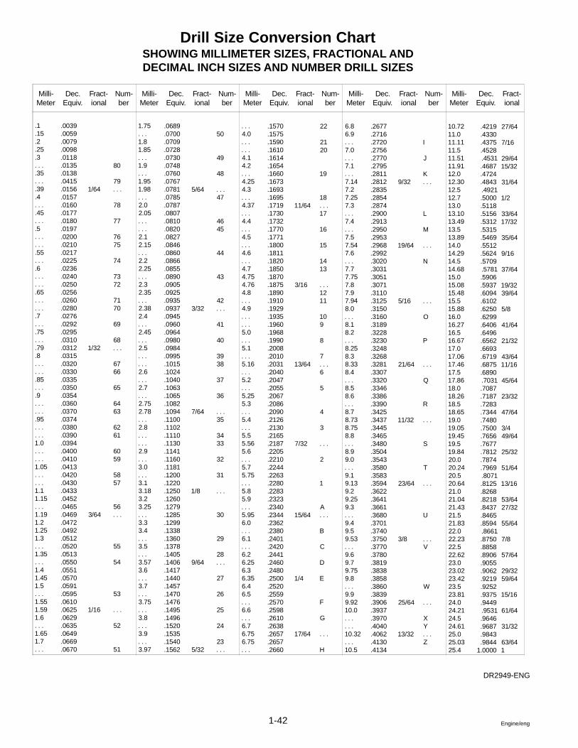
Drill Size Conversion ChartSHOWING MILLIMETER SIZES, FRACTIONAL ANDDECIMAL INCH SIZES AND NUMBER DRILL SIZES
DR2949-ENG
Milli-Meter
Dec.Equiv.
Fract-ional
Num-ber
Milli-Meter
Dec.Equiv.
Fract-ional
Num-ber
Milli-Meter
Dec.Equiv.
Fract-ional
Num-ber
Milli-Meter
Dec.Equiv.
Fract-ional
Num-ber
Milli-Meter
Dec.Equiv.
Fract-ional
.1
.15
.2
.25
.3
. . .
.35
. . .
.39
.4
. . .
.45
. . .
.5
. . .
. . .
.55
. . .
.6
. . .
. . .
.65
. . .
. . .
.7
. . .
.75
. . .
.79
.8
. . .
. . .
.85
. . .
.9
. . .
. . .
.95
. . .
. . .1.0. . .. . .1.05. . .. . .1.11.15. . .1.191.21.251.3. . .1.35. . .1.41.451.5. . .1.551.591.6. . .1.651.7. . .
.0039
.0059
.0079
.0098
.0118
.0135
.0138
.0415
.0156
.0157
.0160
.0177
.0180
.0197
.0200
.0210
.0217
.0225
.0236
.0240
.0250
.0256
.0260
.0280
.0276
.0292
.0295
.0310
.0312
.0315
.0320
.0330
.0335
.0350
.0354
.0360
.0370
.0374
.0380
.0390
.0394
.0400
.0410
.0413
.0420
.0430
.0433
.0452
.0465
.0469
.0472
.0492
.0512
.0520
.0513
.0550
.0551
.0570
.0591
.0595
.0610
.0625
.0629
.0635
.0649
.0669
.0670
1/64
1/32
3/64
1/16
80
79. . .
78
77
7675
74
7372
7170
69
68. . .
6766
65
6463
6261
6059
5857
56. . .
55
54
53
. . .
52
51
1.75. . .1.81.85. . .1.9. . .1.951.98. . .2.02.05. . .. . .2.12.15. . .2.22.25. . .2.32.35. . .2.382.4. . .2.45. . .2.5. . .. . .2.6. . .2.7. . .2.752.78. . .2.8. . .. . .2.9. . .3.0. . .3.13.183.23.25. . .3.33.4. . .3.5. . .3.573.6. . .3.7. . .3.75. . .3.8. . .3.9. . .3.97
.0689
.0700
.0709
.0728
.0730
.0748
.0760
.0767
.0781
.0785
.0787
.0807
.0810
.0820
.0827
.0846
.0860
.0866
.0855
.0890
.0905
.0925
.0935
.0937
.0945
.0960
.0964
.0980
.0984
.0995
.1015
.1024
.1040
.1063
.1065
.1082
.1094
.1100
.1102
.1110
.1130
.1141
.1160
.1181
.1200
.1220
.1250
.1260
.1279
.1285
.1299
.1338
.1360
.1378
.1405
.1406
.1417
.1440
.1457
.1470
.1476
.1495
.1496
.1520
.1535
.1540
.1562
5/64
3/32
7/64
1/8
9/64
5/32
50
49
48
. . .47
4645
44
43
42. . .
41
40
3938
37
36
. . .35
3433
32
31
. . .
30
29
28. . .
27
26
25
24
23. . .
. . .4.0. . .. . .4.14.2. . .4.254.3. . .4.37. . .4.4. . .4.5. . .4.6. . .4.74.754.764.8. . .4.9. . .. . .5.0. . .5.1. . .5.16. . .5.2. . .5.255.3. . .5.4. . .5.55.565.6. . .5.75.75. . .5.85.9. . .5.956.0. . .6.1. . .6.26.256.36.356.46.5. . .6.6. . .6.76.756.75. . .
.1570
.1575
.1590
.1610
.1614
.1654
.1660
.1673
.1693
.1695
.1719
.1730
.1732
.1770
.1771
.1800
.1811
.1820
.1850
.1870
.1875
.1890
.1910
.1929
.1935
.1960
.1968
.1990
.2008
.2010
.2031
.2040
.2047
.2055
.2067
.2086
.2090
.2126
.2130
.2165
.2187
.2205
.2210
.2244
.2263
.2280
.2283
.2323
.2340
.2344
.2362
.2380
.2401
.2420
.2441
.2460
.2480
.2500
.2520
.2559
.2570
.2598
.2610
.2638
.2657
.2657
.2660
11/64
3/16
13/64
7/32
15/64
1/4
17/64
22
2120
19
18. . .17
16
15
1413
. . .1211
109
8
7. . .6
5
4
3
. . .
2
1
A. . .
B
C
D
E
F
G
. . .
H
6.86.9. . .7.0. . .7.1. . .7.147.27.257.3. . .7.4. . .7.57.547.6. . .7.77.757.87.97.948.0. . .8.18.2. . .8.258.38.338.4. . .8.58.6. . .8.78.738.758.8. . .8.99.0. . .9.19.139.29.259.3. . .9.49.59.53. . .9.69.79.759.8. . .9.99.9210.0. . .. . .10.32. . .10.5
.2677
.2716
.2720
.2756
.2770
.2795
.2811
.2812
.2835
.2854
.2874
.2900
.2913
.2950
.2953
.2968
.2992
.3020
.3031
.3051
.3071
.3110
.3125
.3150
.3160
.3189
.3228
.3230
.3248
.3268
.3281
.3307
.3320
.3346
.3386
.3390
.3425
.3437
.3445
.3465
.3480
.3504
.3543
.3580
.3583
.3594
.3622
.3641
.3661
.3680
.3701
.3740
.3750
.3770
.3780
.3819
.3838
.3858
.3860
.3839
.3906
.3937
.3970
.4040
.4062
.4130
.4134
9/32
19/64
5/16
21/64
11/32
23/64
3/8
25/64
13/32
I
J
K. . .
L
M
. . .
N
. . .
O
P
. . .
Q
R
. . .
S
T
. . .
U
. . .V
W
. . .
XY. . .Z
10.7211.011.1111.511.5111.9112.012.3012.512.713.013.1013.4913.513.8914.014.2914.514.6815.015.0815.4815.515.8816.016.2716.516.6717.017.0617.4617.517.8618.018.2618.518.6519.019.0519.4519.519.8420.020.2420.520.6421.021.0421.4321.521.8322.022.2322.522.6223.023.0223.4223.523.8124.024.2124.524.6125.025.0325.4
.4219
.4330
.4375
.4528.4531.4687.4724.4843.4921.5000.5118.5156.5312.5315.5469.5512.5624.5709.5781.5906.5937.6094.6102.6250.6299.6406.6496.6562.6693.6719.6875.6890.7031.7087.7187.7283.7344.7480.7500.7656.7677.7812.7874.7969.8071.8125.8268.8218.8437.8465.8594.8661.8750.8858.8906.9055.9062.9219.9252.9375.9449.9531.9646.9687.9843.9844
1.0000
27/64
7/16
29/6415/32
31/64
1/2
33/6417/32
35/64
9/16
37/64
19/3239/64
5/8
41/64
21/32
43/6411/16
45/64
23/32
47/64
3/449/64
25/32
51/64
13/16
53/6427/32
55/64
7/8
57/64
29/3259/64
15/16
61/64
31/32
63/641
1-43Engine/eng
SYMBOLS
Certain symbols or combinations of symbols may appear on your stern drive or on their accessories. It is veryimportant that you understand their meaning or purpose. If any symbol is not clearly understood, see yourauthorized dealer.
Safety Warning Symbols
Position Indicator Symbols
Condition Symbols
Instructional Symbols
Poisonous
Fire Hazard
Risk of serious injuryBe CarefulFollow instructions
Contents Under Pressure
Raise Lower REVERSEFORWARD
Shift PositionsNEUTRAL
Hour Meter
Battery
Water Temperature
Oil Filter
Emergency Stop
VoltmeterAmmeter r/min
Oil Pressure
Fuel Filter
Tachometer
Oil FillRead Operator’s Manuralbefore operating product
Use unleaded gasolineGasoline is presentPb
- +
DR3847
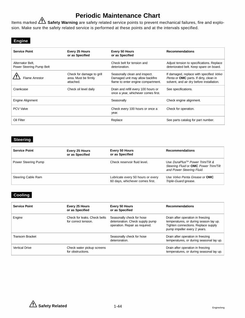
1-44 Engine/eng
Periodic Maintenance ChartItems marked Safety Warning are safety related service points to prevent mechanical failures, fire and explo-sion. Make sure the safety related service is performed at these points and at the intervals specified.
Engine
Steering
Cooling
Safety Related
Service Point Every 25 Hoursor as Specified
Every 50 Hoursor as Specified
Recommendations
Alternator Belt,Power Steering Pump Belt
Check belt for tension anddeterioration.
Adjust tension to specifications. Replacedeteriorated belt. Keep spare on board.
Flame ArrestorCheck for damage to grillarea. Must be firmlyattached.
Seasonally clean and inspect.Damaged unit may allow backfireflame to enter engine compartment.
If damaged, replace with specified VolvoPenta or OMC parts. If dirty, clean insolvent, and air dry before installation.
Crankcase Check oil level daily Drain and refill every 100 hours oronce a year, whichever comes first.
See specifications.
Engine Alignment Seasonally Check engine alignment.
PCV Valve Check every 100 hours or once ayear.
Check for operation.
Oil Filter Replace See parts catalog for part number.
Service Point Every 25 Hoursor as Specified
Every 50 Hoursor as Specified
Recommendations
Power Steering Pump Check reservoir fluid level. Use DuraPlusTM Power Trim/Tilt &Steering Fluid or OMC Power Trim/Tiltand Power Steering Fluid.
Steering Cable Ram Lubricate every 50 hours or every60 days, whichever comes first.
Use Volvo Penta Grease or OMCTriple-Guard grease.
Service Point Every 25 Hoursor as Specified
Every 50 Hoursor as Specified
Recommendations
Engine Check for leaks. Check beltsfor correct tension.
Seasonally check for hosedeterioration. Check supply pumpoperation. Repair as required.
Drain after operation in freezingtemperatures, or during season lay up.Tighten connections. Replace supplypump impeller every 2 years.
Transom Bracket Seasonally check for hosedeterioration.
Drain after operation in freezingtemperatures, or during seasonal lay up.
Vertical Drive Check water pickup screensfor obstructions.
Drain after operation in freezingtemperatures, or during seasonal lay up.
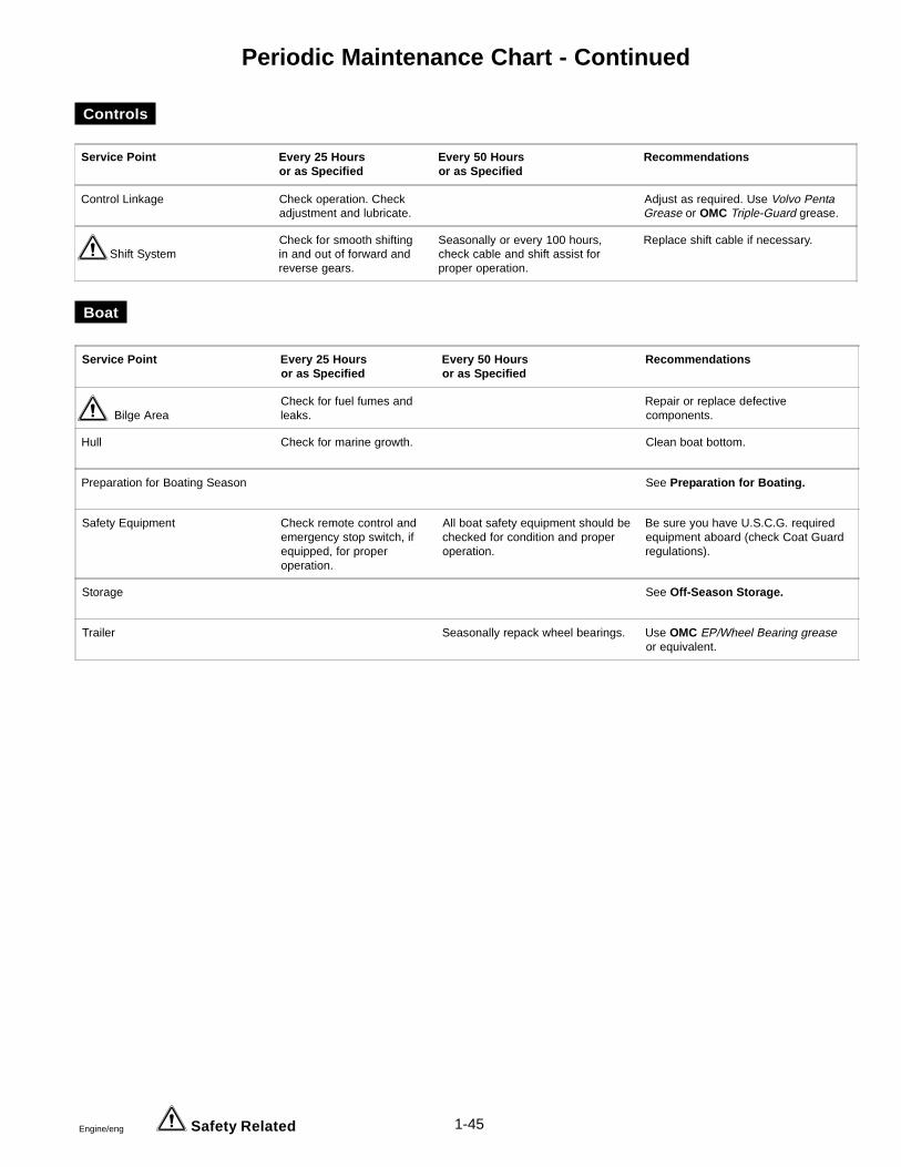
1-45Engine/eng
Periodic Maintenance Chart - Continued
Controls
Boat
Safety Related
Service Point Every 25 Hoursor as Specified
Every 50 Hoursor as Specified
Recommendations
Control Linkage Check operation. Checkadjustment and lubricate.
Adjust as required. Use Volvo PentaGrease or OMC Triple-Guard grease.
Shift SystemCheck for smooth shiftingin and out of forward andreverse gears.
Seasonally or every 100 hours,check cable and shift assist forproper operation.
Replace shift cable if necessary.
Service Point Every 25 Hoursor as Specified
Every 50 Hoursor as Specified
Recommendations
Bilge AreaCheck for fuel fumes andleaks.
Repair or replace defectivecomponents.
Hull Check for marine growth. Clean boat bottom.
Preparation for Boating Season See Preparation for Boating.
Safety Equipment Check remote control andemergency stop switch, ifequipped, for properoperation.
All boat safety equipment should bechecked for condition and properoperation.
Be sure you have U.S.C.G. requiredequipment aboard (check Coat Guardregulations).
Storage See Off-Season Storage.
Trailer Seasonally repack wheel bearings. Use OMC EP/Wheel Bearing greaseor equivalent.

2-1Engine/eng
Section 2General Engine Mechanical
V6 and V8 Models
Table of Contents
2Assembling Piston and Connecting Rod ............ 2-10Camshaft
Bearings .............................................................. 2-13Bearing Installation ............................................ 2-14Bearing Removal ................................................ 2-13Cleaning and Inspection .................................... 2-13Measurements .................................................... 2-14
Cleanliness and Care .............................................. 2-2Crankshaft and Connecting Rod Bearings
Cleaning and Inspection .................................... 2-18Measuring Bearing Clearance ........................... 2-19
Connecting Rod Side Clearance .......................... 2-21Crankshaft End Play ............................................. 2-21Crankshaft Runout ................................................ 2-21Cylinder Bores
Boring ................................................................... 2-6Honing ................................................................... 2-7Measuring Taper and Out-of-Round ................... 2-4Reconditioning ..................................................... 2-5Removing Ridge ................................................... 2-6
Cylinder HeadAssembly ............................................................ 2-18Cleaning and Inspection .................................... 2-15Disassembly ....................................................... 2-15Repair .................................................................. 2-17
Reaming Valve Guides ................................... 2-17Valve Grinding ................................................. 2-17Valve Seat Grinding ........................................ 2-17
Engine Gaskets, Replacing .................................... 2-4General Description ................................................ 2-2Piston and Connecting Rod ................................... 2-8Measuring Piston to Pin Clearance ....................... 2-9Installing Piston Rings .......................................... 2-11Piston Selection .................................................... 2-10RTV Sealer / Anaerobic Gasket Eliminator ............ 2-2Special Tools ......................................................... 2-23Thread Repair ........................................................ 2-22
Safety Warnings
Before working on any part of the engine, read the Safety sectionat the end of this manual.
Always use the correct fastener in the proper location. When youreplace a fastener, use ONLY the exact part number for that appli-cation. The text will call out those fasteners that require replace-ment after removal. The text will also call out the fasteners thatrequire thread lockers or thread sealant.
UNLESS OTHERWISE SPECIFIED, do not use supplement coatings(paints, greases, or other corrosion inhibitors) on threaded fas-teners or fastener joint interfaces. Generally, such coatings ad-versely affect the fastener torque and the joint clamping force,and may damage the fastener.
When you install fasteners, use the correct tightening sequenceand tightening specifications. Following these instructions canhelp you avoid damage to parts and systems.
2-2 Engine/eng
General Description
The engine repair information described in this section explains howto clean, inspect, and measure certain engine components. Use thissection along with the proper engine repair section for the correct dis-assembly and assembly procedures. Engine specifications are foundin the back of each engine repair section and will be referred to oftenin this section.
Cleanliness and Care
An engine is a combination of many machined, honed, polished, andlapped surfaces with very close tolerances. Whenever valve train, cyl-inder head, crankshaft, piston, and connecting rod components areremoved for service, they should be installed in their original location.
Anytime the flame arrestor is removed, the intake opening must becovered. This will protect against the entrance of foreign material whichcould follow the intake passage into the cylinder and cause extensivedamage when the engine is started.
When any internal engine parts are serviced, care and cleanliness areimportant. Apply a liberal coating of engine oil to friction areas duringassembly to protect and lubricate the surfaces during initial operation.
Throughout this section, it should be understood that proper cleaningand protection of machined surfaces and friction areas is part of therepair procedure. This is considered standard shop practice even ifnot specifically stated.
Use of RTV Sealer and Anaerobic GasketEliminator
Two types of sealants are commonly used in the engines covered bythis manual. These are RTV sealer and anaerobic “gasket eliminator”sealer.
It is important that these sealers be applied properly and in the properplace to prevent oil leaks. THE TWO TYPES OF SEALER ARE NOTINTERCHANGEABLE. Use the sealer recommended in the procedure.
� RTV (Room Temperature Vulcanizing) sealer is usedwhere a non-rigid part is assembled to a rigid part. Com-mon examples are oil pans and valve rocker arm cov-ers.
2-3Engine/eng
� Anaerobic gasket eliminator hardens in the absence ofair. This sealer is used where two rigid parts (such ascastings) are assembled together. When two rigid partsare disassembled and no sealer or gasket is readily no-ticeable, the parts were probably assembled using gas-ket eliminator.
Using RTV Sealer
1. Do not use RTV in areas where extreme temperatures are expected,such as exhaust manifold or head gaskets, or where gasket eliminatoris specified.
2. Use a rubber mallet to separate components sealed with RTV. Bumpthe part sideways to shear the RTV sealer. Bumping should be done atbends or reinforced areas to prevent distortion of parts. RTV is weakerin shear (lateral) strength than in tensile (vertical) strength.
Attempting to pry or pull components apart may result in dam-age to the part.
3. Remove all gasket material from the part using a plastic or woodscraper. Use Loctite brand “Chisel Gasket Remover,” P/N 79040, orPermatex brand “Gasket Remover,” P/N 4MA, or equivalent. Follow allsafety recommendations and directions that are on the can. Do not useany other method or technique to remove gasket material from a part.
Do not use abrasive pads, sand paper or power tools to cleangasket surfaces. These methods of cleaning can damage the part. Abra-sive pads also produce a fine grit that the oil filter cannot remove fromthe oil. This grit is abrasive and has been known to cause internal en-gine damage.
4. Apply RTV to one of the clean surfaces. Use a bead size as specifiedin the procedure. Run the bead to the inside of any bolt holes. Do notallow the sealer in any blind threaded holes, as it may prevent the boltfrom seating properly or cause damage when the bolt is tightened.
5. Assemble components while RTV is still wet (within 3 minutes). Donot wait for RTV to skin over.
6. Torque bolts to specifications. Do not overtighten.
Using Anaerobic Gasket Eliminator
1. Remove all gasket material from the part using a plastic or woodscraper. Use Loctite brand “Chisel Gasket Remover,” P/N 79040, orPermatex brand “Gasket Remover,” P/N 4MA, or equivalent. Follow allsafety recommendations and directions that are on the can. Do not useany other method or technique to rermove gasket material from a part.
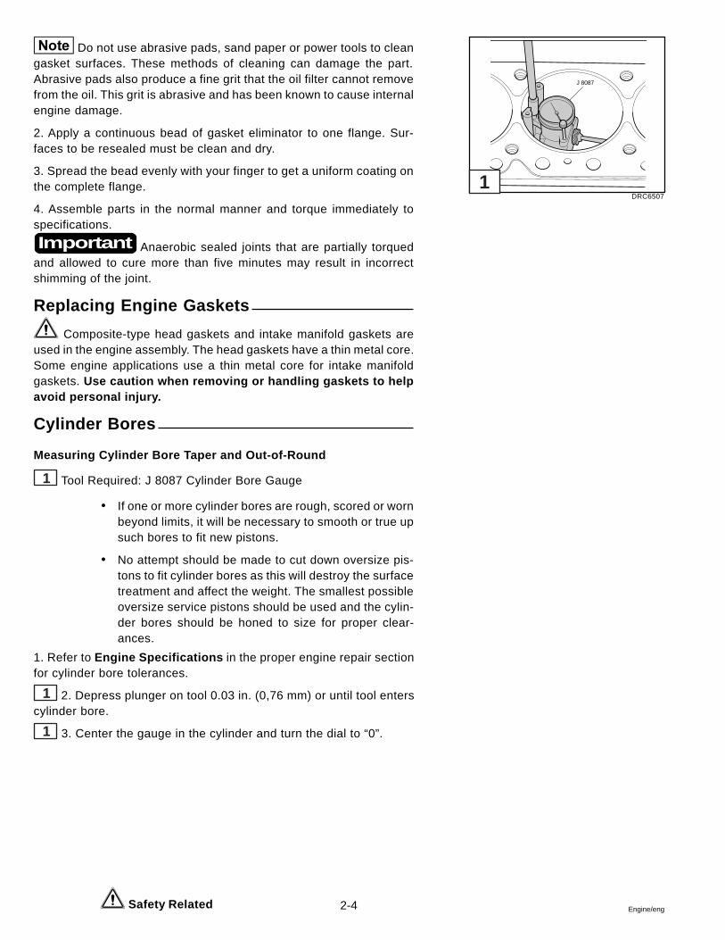
2-4 Engine/eng Safety Related
Do not use abrasive pads, sand paper or power tools to cleangasket surfaces. These methods of cleaning can damage the part.Abrasive pads also produce a fine grit that the oil filter cannot removefrom the oil. This grit is abrasive and has been known to cause internalengine damage.
2. Apply a continuous bead of gasket eliminator to one flange. Sur-faces to be resealed must be clean and dry.
3. Spread the bead evenly with your finger to get a uniform coating onthe complete flange.
4. Assemble parts in the normal manner and torque immediately tospecifications.
Anaerobic sealed joints that are partially torquedand allowed to cure more than five minutes may result in incorrectshimming of the joint.
Replacing Engine Gaskets
Composite-type head gaskets and intake manifold gaskets areused in the engine assembly. The head gaskets have a thin metal core.Some engine applications use a thin metal core for intake manifoldgaskets. Use caution when removing or handling gaskets to helpavoid personal injury.
Cylinder Bores
Measuring Cylinder Bore Taper and Out-of-Round
1 Tool Required: J 8087 Cylinder Bore Gauge
� If one or more cylinder bores are rough, scored or wornbeyond limits, it will be necessary to smooth or true upsuch bores to fit new pistons.
� No attempt should be made to cut down oversize pis-tons to fit cylinder bores as this will destroy the surfacetreatment and affect the weight. The smallest possibleoversize service pistons should be used and the cylin-der bores should be honed to size for proper clear-ances.
1. Refer to Engine Specifications in the proper engine repair sectionfor cylinder bore tolerances.
1 2. Depress plunger on tool 0.03 in. (0,76 mm) or until tool enterscylinder bore.
1 3. Center the gauge in the cylinder and turn the dial to “0”.
Important
J 8087
DRC65071
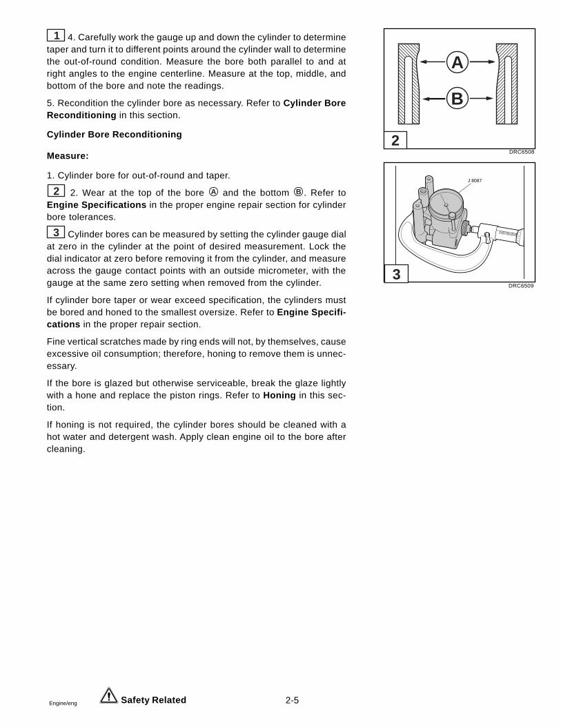
2-5Engine/eng Safety Related
1 4. Carefully work the gauge up and down the cylinder to determinetaper and turn it to different points around the cylinder wall to determinethe out-of-round condition. Measure the bore both parallel to and atright angles to the engine centerline. Measure at the top, middle, andbottom of the bore and note the readings.
5. Recondition the cylinder bore as necessary. Refer to Cylinder BoreReconditioning in this section.
Cylinder Bore Reconditioning
Measure:
1. Cylinder bore for out-of-round and taper.
2 2. Wear at the top of the bore A and the bottom B . Refer toEngine Specifications in the proper engine repair section for cylinderbore tolerances.
3 Cylinder bores can be measured by setting the cylinder gauge dialat zero in the cylinder at the point of desired measurement. Lock thedial indicator at zero before removing it from the cylinder, and measureacross the gauge contact points with an outside micrometer, with thegauge at the same zero setting when removed from the cylinder.
If cylinder bore taper or wear exceed specification, the cylinders mustbe bored and honed to the smallest oversize. Refer to Engine Specifi-cations in the proper repair section.
Fine vertical scratches made by ring ends will not, by themselves, causeexcessive oil consumption; therefore, honing to remove them is unnec-essary.
If the bore is glazed but otherwise serviceable, break the glaze lightlywith a hone and replace the piston rings. Refer to Honing in this sec-tion.
If honing is not required, the cylinder bores should be cleaned with ahot water and detergent wash. Apply clean engine oil to the bore aftercleaning.
DRC6508
DRC6509
�����
�����
����������
A
B
J 8087
2
3
2-6 Engine/eng
Removing Cylinder Bore Ridge
1 Tool Required: J 24270 Ridge Reamer
Do NOT remove excessive material from the cylin-der bore. Excessive removal of material may require cylinder boring tothe next oversize.
1. Rotate the crankshaft until the piston is at BDC.
2. Place a cloth on top of the piston.
1 3. Perform the cutting operation with a J 24270 ridge reamer.Refer to the manufacturer’s instructions before using J 24270.
4. Remove J 24270 and rotate the crankshaft until the piston is atTDC.
5. Remove the cloth and cuttings.
6. Repeat this procedure for each piston.
Boring
Refer to Engine Specifications in the proper en-gine repair section for additional information.
1. Before the honing or boring operation is started, measure all newpistons with the micrometer contacting at points exactly 90 degreesfrom the piston pin centerline. Some pistons must be measured at aspecified distance from the piston crown. Refer to the proper sectionfor additional instructions. Then select the smallest piston for the firstfitting. The slight variation usually found between pistons in a set mayprovide for correction in case the first piston is fitted too loose.
2. Before using any type of boring bar, the top of the cylinder blockshould be filed to remove any dirt or burrs. This is very important. If notchecked, the boring bar may be tilted which would result in the reboredcylinder wall not being at right angles to the crankshaft.
3. The instructions furnished by the manufacturer of the equipmentbeing used should be carefully followed.
4. When boring cylinders, all crankshaft bearing caps must be in placeand tightened to the proper torque to avoid distortion of bores in thefinal assembly.
Important
Important
DRC6510
J 24270
1
2-7Engine/eng
5. When taking the final cut with a boring bar, leave 0.001 in. (0,025mm) on the diameter for finish honing to give the required position tothe cylinder clearance specifications. (The honing or boring operationmust be done carefully so the specified clearance between pistons, rings,and cylinder bores is maintained).
Honing
1. When honing the cylinders, follow the hone manufacturer’s recom-mendations for use, cleaning, and lubrication during honing. Use onlyclean, sharp stones of the proper grade for the amount of material to beremoved. Dull, dirty stones cut unevenly and generate excessive heat.When using coarse or medium grade stones, use care to leave suffi-cient metal so that all stone marks may be removed with the fine stonesused for finishing to provide proper clearance.
2. Occasionally, during the honing operation, the cylinder bore shouldbe thoroughly cleaned, and the piston selected for the individual cylin-der checked for correct fit.
3. When honing to eliminate taper in the cylinder, make full strokes ofthe hone in the cylinder. Also check measurement at the top, middle,and bottom of the bore repeatedly.
Handle the pistons with care and do not attempt to force themthrough the cylinder until the cylinder has been honed to the correctsize. The piston can be easily distorted through careless handling.
4. When finish honing a cylinder bore to fit a piston, move the hone upand down at a sufficient speed to obtain very fine uniform surface finishmarks in a cross-hatch pattern at the specified angle (45 to 65 degrees).
5. The finish marks should be clean but not sharp, free from embeddedparticles and torn or folded metal.
6. By measuring the piston to be installed at the sizing point specified inthe proper section, and adding the average of the clearance specifica-tion, the finish hone cylinder measurement can be determined. It is im-portant that both the block and piston be measured at normal roomtemperature.
7. Refer to Engine Specifications in the proper engine repair section.
8. It is of the greatest importance that refinished cylinder bores are truedup to have less than the specified out-of-round or taper. Each bore mustbe final honed to remove all stone or cutter marks and provide a smoothsurface.
186747
2-8 Engine/eng
9. After final honing and before the piston is checked for fit, clean thebores with hot water and detergent. Scrub with a stiff bristle brush andrinse thoroughly with hot water. It is essential that a good cleaningoperation be performed. If any of the abrasive material is allowed toremain in the cylinder bores, it will wear the new rings, cylinder bores,and bearings lubricated by the contaminated oil. After washing, thedry bore should be brushed clean with a power-driven fiber brush.
10. Refer to Engine Specifications in the proper engine repair sec-tion.
11. Permanently mark the piston for the cylinder to which it has beenfitted.
12. Apply clean engine oil to each bore to prevent rusting.
Piston and Connecting Rod
Tools Required: J 24086-C Piston Pin Removal and Installation Set
Disassemble:
1 1. Piston rings. In most cases the rings should be discarded andreplaced with new rings at assembly.
2. Connecting rod bearings. If the bearings are to be reused, placethem in a rack so they may be reinstalled with the original connectingrod and cap.
2 3. Piston pin.
a. Place the piston/connecting rod on support fixture J 24086-C. Make sure the connecting rod is fully supported.
b. Place remover J 24086-C on the support fixture.
c. Press out the piston pin.
DRC6511
DRC6515
2
J 3936-03
J 24086-C
1
2-9Engine/eng
Cleaning and Inspection
Clean: Piston
� Remove all varnish and carbon deposits. DO NOT USEA WIRE BRUSH.
� Use an approved cleaning solution to remove carbonbuild-up.
� Remove the carbon from the ring grooves. Use a ringgroove cleaning tool.
� Oil-control ring groove holes.
Inspect:
1. Piston pin bore and connecting rod bore for scuffing and burrs.
2. Connecting rod for cracks, nicks, etc. If a suitable jig is available,check the connecting rod for a bent or twisted condition.
3. Connecting rod bearings for scratches or deep pitting.
4. Piston for:
� Scratches, scuffing, and burrs� Ring land for cracking and wear� Ring grooves for burrs and nicks� Skirts and pin bosses for cracking� Skirts for scuffing
Measuring Piston Pin to Piston Clearance
Measure:
3 1. Piston pin diameter. Check against Engine Specifications inthe proper engine repair section.
2. Piston pin to piston clearance.
4 a. Measure the piston pin hole diameter.
b. Subtract the piston pin diameter from the piston pin hole diam-eter to obtain the clearance.
c. Replace the piston and piston pin if the clearance exceedsspecifications. The piston and piston pin are a matched setand not available separately.
DRC6512
DRC6513
3
4

2-10 Engine/eng
Piston Selection
Check the used piston to cylinder bore clearance.
Measure:
1 1. Cylinder bore diameter. Use a telescoping bore gauge, located2.56 in. (65 mm) below the top of the cylinder bore.
2 2. Piston diameter. Measure the piston skirt at a right angle to thepiston pin, at the centerline of the piston pin.
3. Subtract the piston diameter from the cylinder bore diameter to de-termine piston to bore clearance.
4. Refer to Engine Specifications in the proper engine repair sectionto determine if piston clearance is within the acceptable range.
If the used piston is not acceptable, determine if a new piston will fitthe cylinder bore. If a new piston does not bring the clearance withintolerances, the cylinder bore must be reconditioned. Mark the pistonto identify the cylinder for which it was fitted.
Assembling the Piston and Connecting Rod
3 Tool Required: J 24086-C Piston Pin Removal and InstallationSet
Assemble:
1. Piston and connecting rod.
a. The alignment mark on the top of the piston must face thefront of engine block. Connecting rod must be installed in thecorrect orientation. Refer to the proper engine repair sectionfor piston and connecting rod installation.
b. Lubricate the piston pin holes in the piston and connectingrod with engine oil.
DRC6507
DRC6514
DRC6515
3
J 8087
J 24086-C
2
1
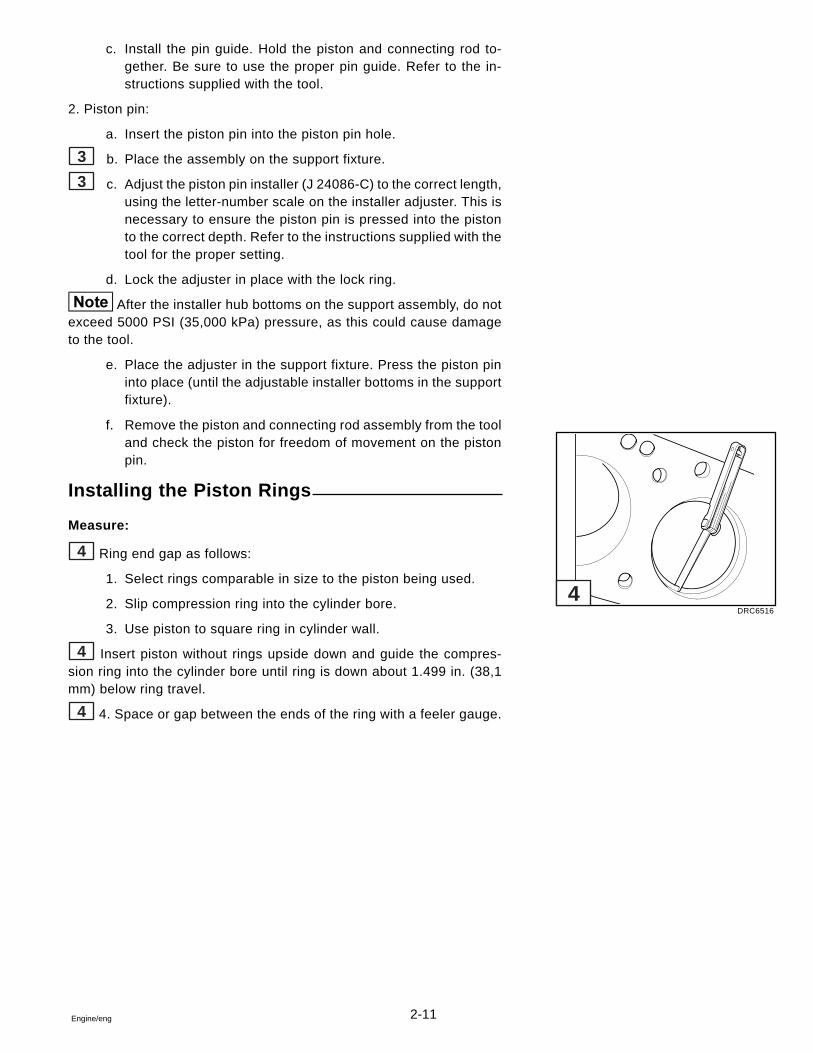
2-11Engine/eng
c. Install the pin guide. Hold the piston and connecting rod to-gether. Be sure to use the proper pin guide. Refer to the in-structions supplied with the tool.
2. Piston pin:
a. Insert the piston pin into the piston pin hole.
3 b. Place the assembly on the support fixture.
3 c. Adjust the piston pin installer (J 24086-C) to the correct length,using the letter-number scale on the installer adjuster. This isnecessary to ensure the piston pin is pressed into the pistonto the correct depth. Refer to the instructions supplied with thetool for the proper setting.
d. Lock the adjuster in place with the lock ring.
After the installer hub bottoms on the support assembly, do notexceed 5000 PSI (35,000 kPa) pressure, as this could cause damageto the tool.
e. Place the adjuster in the support fixture. Press the piston pininto place (until the adjustable installer bottoms in the supportfixture).
f. Remove the piston and connecting rod assembly from the tooland check the piston for freedom of movement on the pistonpin.
Installing the Piston Rings
Measure:
4 Ring end gap as follows:
1. Select rings comparable in size to the piston being used.
2. Slip compression ring into the cylinder bore.
3. Use piston to square ring in cylinder wall.
4 Insert piston without rings upside down and guide the compres-sion ring into the cylinder bore until ring is down about 1.499 in. (38,1mm) below ring travel.
4 4. Space or gap between the ends of the ring with a feeler gauge.
DRC6516
4
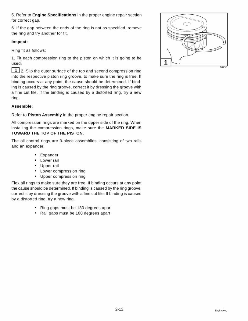
2-12 Engine/eng
5. Refer to Engine Specifications in the proper engine repair sectionfor correct gap.
6. If the gap between the ends of the ring is not as specified, removethe ring and try another for fit.
Inspect:
Ring fit as follows:
1. Fit each compression ring to the piston on which it is going to beused.
1 2. Slip the outer surface of the top and second compression ringinto the respective piston ring groove, to make sure the ring is free. Ifbinding occurs at any point, the cause should be determined. If bind-ing is caused by the ring groove, correct it by dressing the groove witha fine cut file. If the binding is caused by a distorted ring, try a newring.
Assemble:
Refer to Piston Assembly in the proper engine repair section.
All compression rings are marked on the upper side of the ring. Wheninstalling the compression rings, make sure the MARKED SIDE ISTOWARD THE TOP OF THE PISTON.
The oil control rings are 3-piece assemblies, consisting of two railsand an expander.
� Expander� Lower rail� Upper rail� Lower compression ring� Upper compression ring
Flex all rings to make sure they are free. If binding occurs at any pointthe cause should be determined. If binding is caused by the ring groove,correct it by dressing the groove with a fine cut file. If binding is causedby a distorted ring, try a new ring.
� Ring gaps must be 180 degrees apart� Rail gaps must be 180 degrees apart
107551
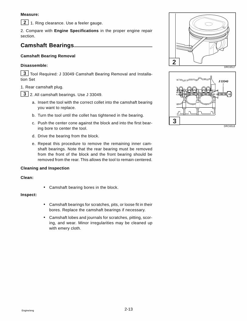
2-13Engine/eng
Measure:
2 1. Ring clearance. Use a feeler gauge.
2. Compare with Engine Specifications in the proper engine repairsection.
Camshaft Bearings
Camshaft Bearing Removal
Disassemble:
3 Tool Required: J 33049 Camshaft Bearing Removal and Installa-tion Set
1. Rear camshaft plug.
3 2. All camshaft bearings. Use J 33049.
a. Insert the tool with the correct collet into the camshaft bearingyou want to replace.
b. Turn the tool until the collet has tightened in the bearing.
c. Push the center cone against the block and into the first bear-ing bore to center the tool.
d. Drive the bearing from the block.
e. Repeat this procedure to remove the remaining inner cam-shaft bearings. Note that the rear bearing must be removedfrom the front of the block and the front bearing should beremoved from the rear. This allows the tool to remain centered.
Cleaning and Inspection
Clean:
� Camshaft bearing bores in the block.
Inspect:
� Camshaft bearings for scratches, pits, or loose fit in theirbores. Replace the camshaft bearings if necessary.
� Camshaft lobes and journals for scratches, pitting, scor-ing, and wear. Minor irregularities may be cleaned upwith emery cloth.
DRC6517
DRC6518
2
3
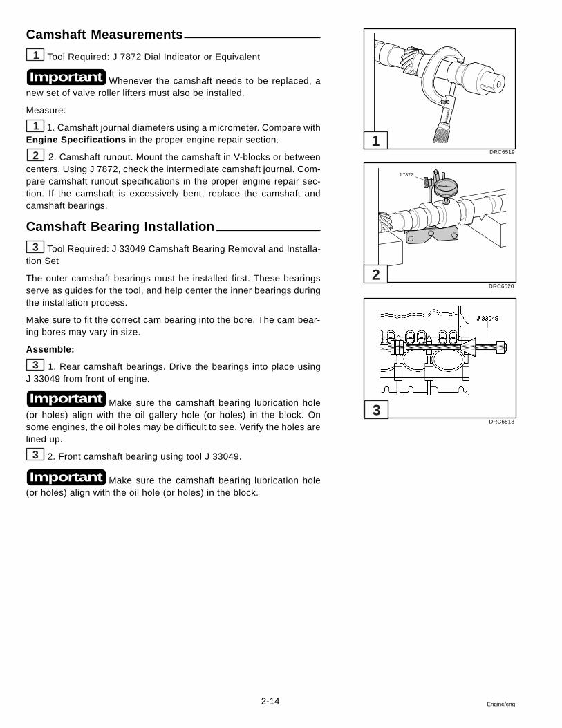
2-14 Engine/eng
Camshaft Measurements
1 Tool Required: J 7872 Dial Indicator or Equivalent
Whenever the camshaft needs to be replaced, anew set of valve roller lifters must also be installed.
Measure:
1 1. Camshaft journal diameters using a micrometer. Compare withEngine Specifications in the proper engine repair section.
2 2. Camshaft runout. Mount the camshaft in V-blocks or betweencenters. Using J 7872, check the intermediate camshaft journal. Com-pare camshaft runout specifications in the proper engine repair sec-tion. If the camshaft is excessively bent, replace the camshaft andcamshaft bearings.
Camshaft Bearing Installation
3 Tool Required: J 33049 Camshaft Bearing Removal and Installa-tion Set
The outer camshaft bearings must be installed first. These bearingsserve as guides for the tool, and help center the inner bearings duringthe installation process.
Make sure to fit the correct cam bearing into the bore. The cam bear-ing bores may vary in size.
Assemble:
3 1. Rear camshaft bearings. Drive the bearings into place usingJ 33049 from front of engine.
Make sure the camshaft bearing lubrication hole(or holes) align with the oil gallery hole (or holes) in the block. Onsome engines, the oil holes may be difficult to see. Verify the holes arelined up.
3 2. Front camshaft bearing using tool J 33049.
Make sure the camshaft bearing lubrication hole(or holes) align with the oil hole (or holes) in the block.
Important
Important
Important
DRC6519
DRC6520
DRC6518
1
J 7872
2
3
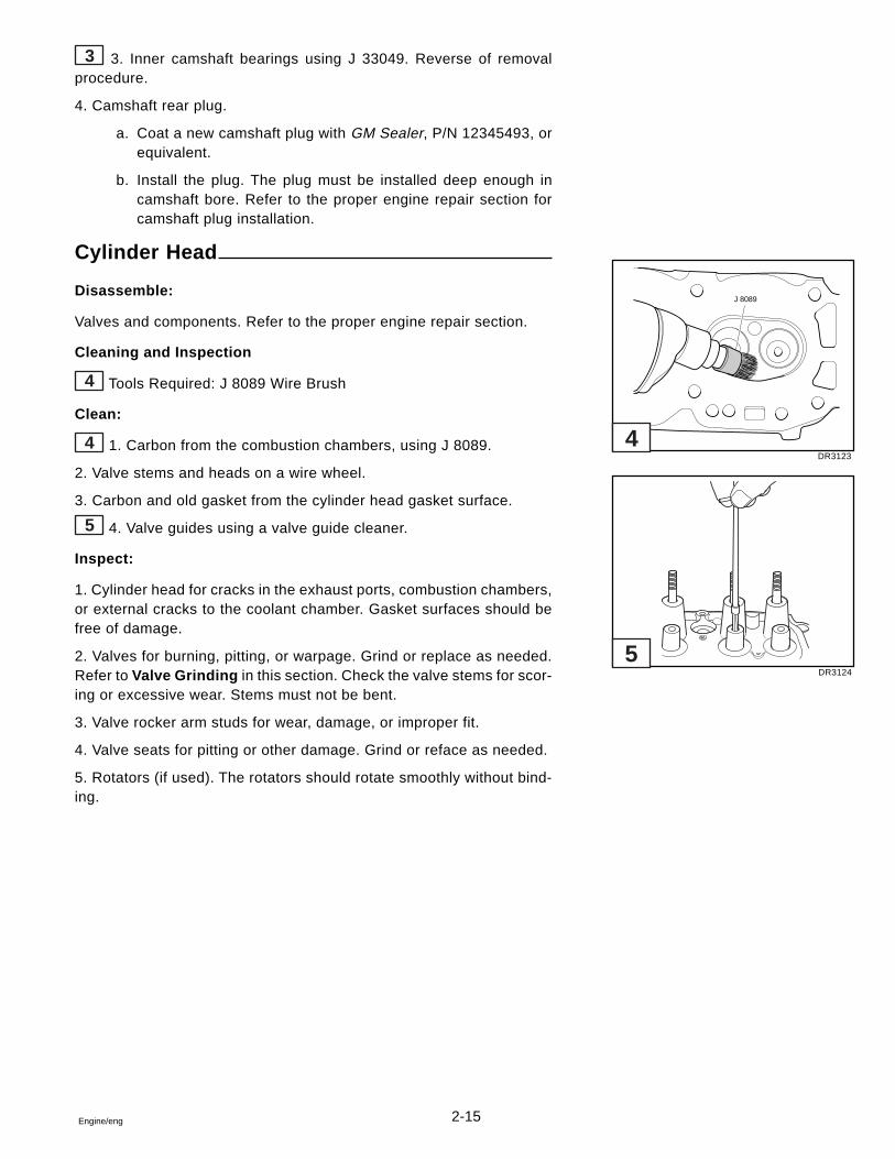
2-15Engine/eng
3 3. Inner camshaft bearings using J 33049. Reverse of removalprocedure.
4. Camshaft rear plug.
a. Coat a new camshaft plug with GM Sealer, P/N 12345493, orequivalent.
b. Install the plug. The plug must be installed deep enough incamshaft bore. Refer to the proper engine repair section forcamshaft plug installation.
Cylinder Head
Disassemble:
Valves and components. Refer to the proper engine repair section.
Cleaning and Inspection
4 Tools Required: J 8089 Wire Brush
Clean:
4 1. Carbon from the combustion chambers, using J 8089.
2. Valve stems and heads on a wire wheel.
3. Carbon and old gasket from the cylinder head gasket surface.
5 4. Valve guides using a valve guide cleaner.
Inspect:
1. Cylinder head for cracks in the exhaust ports, combustion chambers,or external cracks to the coolant chamber. Gasket surfaces should befree of damage.
2. Valves for burning, pitting, or warpage. Grind or replace as needed.Refer to Valve Grinding in this section. Check the valve stems for scor-ing or excessive wear. Stems must not be bent.
3. Valve rocker arm studs for wear, damage, or improper fit.
4. Valve seats for pitting or other damage. Grind or reface as needed.
5. Rotators (if used). The rotators should rotate smoothly without bind-ing.
DR3123
DR3124
J 8089
4
5
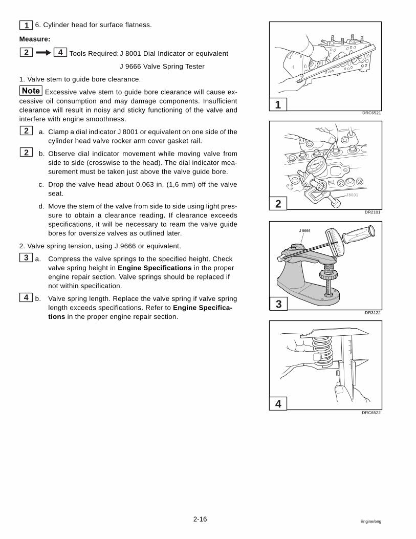
2-16 Engine/eng
1 6. Cylinder head for surface flatness.
Measure:
2 4 Tools Required:J 8001 Dial Indicator or equivalent
J 9666 Valve Spring Tester
1. Valve stem to guide bore clearance.
Excessive valve stem to guide bore clearance will cause ex-cessive oil consumption and may damage components. Insufficientclearance will result in noisy and sticky functioning of the valve andinterfere with engine smoothness.
2 a. Clamp a dial indicator J 8001 or equivalent on one side of thecylinder head valve rocker arm cover gasket rail.
2 b. Observe dial indicator movement while moving valve fromside to side (crosswise to the head). The dial indicator mea-surement must be taken just above the valve guide bore.
c. Drop the valve head about 0.063 in. (1,6 mm) off the valveseat.
d. Move the stem of the valve from side to side using light pres-sure to obtain a clearance reading. If clearance exceedsspecifications, it will be necessary to ream the valve guidebores for oversize valves as outlined later.
2. Valve spring tension, using J 9666 or equivalent.
3 a. Compress the valve springs to the specified height. Checkvalve spring height in Engine Specifications in the properengine repair section. Valve springs should be replaced ifnot within specification.
4 b. Valve spring length. Replace the valve spring if valve springlength exceeds specifications. Refer to Engine Specifica-tions in the proper engine repair section.
DRC6521
DR2101
DR3122
DRC6522
1
J8001
J 9666
2
3
4
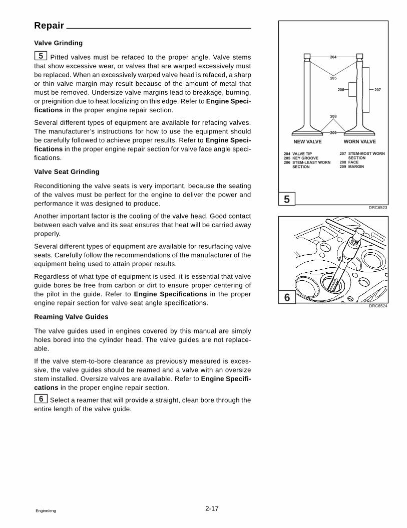
2-17Engine/eng
Repair
Valve Grinding
5 Pitted valves must be refaced to the proper angle. Valve stemsthat show excessive wear, or valves that are warped excessively mustbe replaced. When an excessively warped valve head is refaced, a sharpor thin valve margin may result because of the amount of metal thatmust be removed. Undersize valve margins lead to breakage, burning,or preignition due to heat localizing on this edge. Refer to Engine Speci-fications in the proper engine repair section.
Several different types of equipment are available for refacing valves.The manufacturer’s instructions for how to use the equipment shouldbe carefully followed to achieve proper results. Refer to Engine Speci-fications in the proper engine repair section for valve face angle speci-fications.
Valve Seat Grinding
Reconditioning the valve seats is very important, because the seatingof the valves must be perfect for the engine to deliver the power andperformance it was designed to produce.
Another important factor is the cooling of the valve head. Good contactbetween each valve and its seat ensures that heat will be carried awayproperly.
Several different types of equipment are available for resurfacing valveseats. Carefully follow the recommendations of the manufacturer of theequipment being used to attain proper results.
Regardless of what type of equipment is used, it is essential that valveguide bores be free from carbon or dirt to ensure proper centering ofthe pilot in the guide. Refer to Engine Specifications in the properengine repair section for valve seat angle specifications.
Reaming Valve Guides
The valve guides used in engines covered by this manual are simplyholes bored into the cylinder head. The valve guides are not replace-able.
If the valve stem-to-bore clearance as previously measured is exces-sive, the valve guides should be reamed and a valve with an oversizestem installed. Oversize valves are available. Refer to Engine Specifi-cations in the proper engine repair section.
6 Select a reamer that will provide a straight, clean bore through theentire length of the valve guide.
DRC6523
DRC6524
NEW VALVE
204 VALVE TIP
205 KEY GROOVE
206 STEM-LEAST WORN
SECTION
WORN VALVE
204
205
206
208
209
207
207 STEM-MOST WORN
SECTION
208 FACE
209 MARGIN
5
6
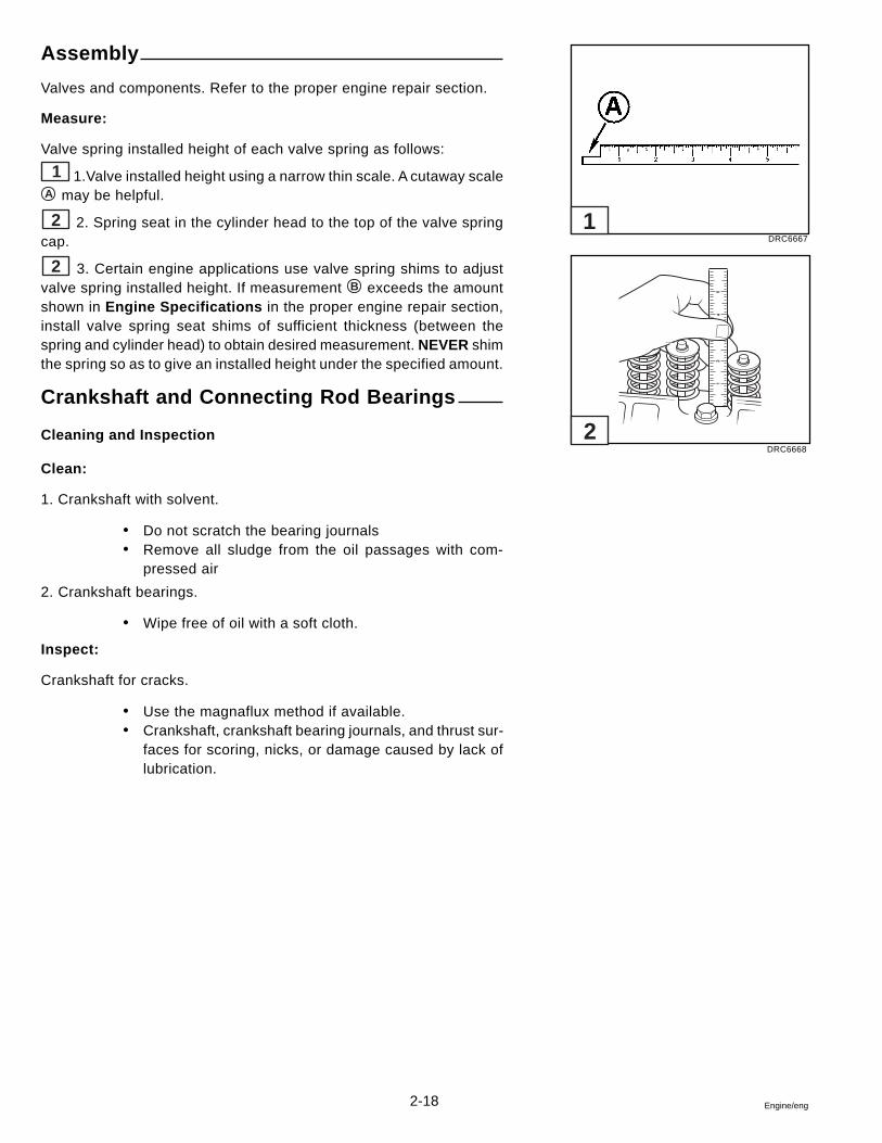
2-18 Engine/eng
Assembly
Valves and components. Refer to the proper engine repair section.
Measure:
Valve spring installed height of each valve spring as follows:
1 1.Valve installed height using a narrow thin scale. A cutaway scaleA may be helpful.
2 2. Spring seat in the cylinder head to the top of the valve springcap.
2 3. Certain engine applications use valve spring shims to adjustvalve spring installed height. If measurement B exceeds the amountshown in Engine Specifications in the proper engine repair section,install valve spring seat shims of sufficient thickness (between thespring and cylinder head) to obtain desired measurement. NEVER shimthe spring so as to give an installed height under the specified amount.
Crankshaft and Connecting Rod Bearings
Cleaning and Inspection
Clean:
1. Crankshaft with solvent.
� Do not scratch the bearing journals� Remove all sludge from the oil passages with com-
pressed air
2. Crankshaft bearings.
� Wipe free of oil with a soft cloth.
Inspect:
Crankshaft for cracks.
� Use the magnaflux method if available.� Crankshaft, crankshaft bearing journals, and thrust sur-
faces for scoring, nicks, or damage caused by lack oflubrication.
DRC6667
DRC6668
1
2
12
54
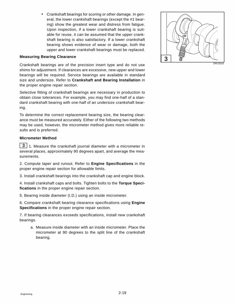
2-19Engine/eng
� Crankshaft bearings for scoring or other damage. In gen-eral, the lower crankshaft bearings (except the #1 bear-ing) show the greatest wear and distress from fatigue.Upon inspection, if a lower crankshaft bearing is suit-able for reuse, it can be assumed that the upper crank-shaft bearing is also satisfactory. If a lower crankshaftbearing shows evidence of wear or damage, both theupper and lower crankshaft bearings must be replaced.
Measuring Bearing Clearance
Crankshaft bearings are of the precision insert type and do not useshims for adjustment. If clearances are excessive, new upper and lowerbearings will be required. Service bearings are available in standardsize and undersize. Refer to Crankshaft and Bearing Installation inthe proper engine repair section.
Selective fitting of crankshaft bearings are necessary in production toobtain close tolerances. For example, you may find one-half of a stan-dard crankshaft bearing with one-half of an undersize crankshaft bear-ing.
To determine the correct replacement bearing size, the bearing clear-ance must be measured accurately. Either of the following two methodsmay be used, however, the micrometer method gives more reliable re-sults and is preferred.
Micrometer Method
3 1. Measure the crankshaft journal diameter with a micrometer inseveral places, approximately 90 degrees apart, and average the mea-surements.
2. Compute taper and runout. Refer to Engine Specifications in theproper engine repair section for allowable limits.
3. Install crankshaft bearings into the crankshaft cap and engine block.
4. Install crankshaft caps and bolts. Tighten bolts to the Torque Speci-fications in the proper engine repair section.
5. Bearing inside diameter (I.D.) using an inside micrometer.
6. Compare crankshaft bearing clearance specifications using EngineSpecifications in the proper engine repair section.
7. If bearing clearances exceeds specifications, install new crankshaftbearings.
a. Measure inside diameter with an inside micrometer. Place themicrometer at 90 degrees to the split line of the crankshaftbearing.
DRC6525
3
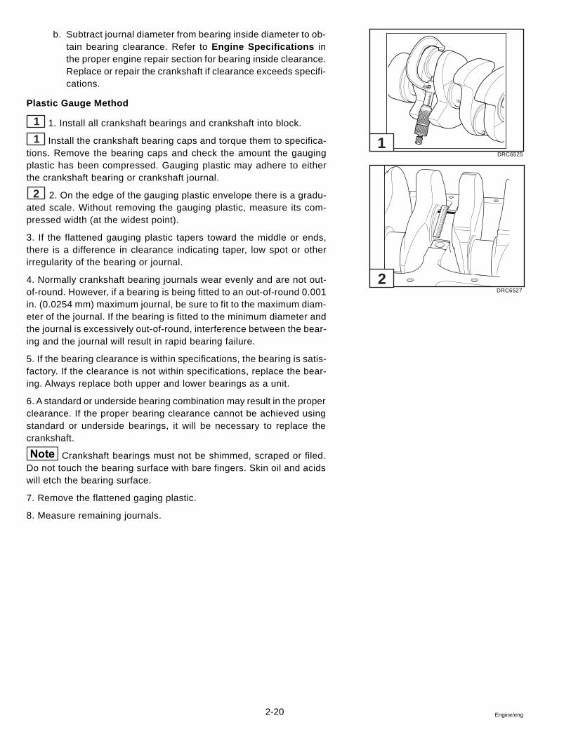
2-20 Engine/eng
b. Subtract journal diameter from bearing inside diameter to ob-tain bearing clearance. Refer to Engine Specifications inthe proper engine repair section for bearing inside clearance.Replace or repair the crankshaft if clearance exceeds specifi-cations.
Plastic Gauge Method
1 1. Install all crankshaft bearings and crankshaft into block.
1 Install the crankshaft bearing caps and torque them to specifica-tions. Remove the bearing caps and check the amount the gaugingplastic has been compressed. Gauging plastic may adhere to eitherthe crankshaft bearing or crankshaft journal.
2 2. On the edge of the gauging plastic envelope there is a gradu-ated scale. Without removing the gauging plastic, measure its com-pressed width (at the widest point).
3. If the flattened gauging plastic tapers toward the middle or ends,there is a difference in clearance indicating taper, low spot or otherirregularity of the bearing or journal.
4. Normally crankshaft bearing journals wear evenly and are not out-of-round. However, if a bearing is being fitted to an out-of-round 0.001in. (0.0254 mm) maximum journal, be sure to fit to the maximum diam-eter of the journal. If the bearing is fitted to the minimum diameter andthe journal is excessively out-of-round, interference between the bear-ing and the journal will result in rapid bearing failure.
5. If the bearing clearance is within specifications, the bearing is satis-factory. If the clearance is not within specifications, replace the bear-ing. Always replace both upper and lower bearings as a unit.
6. A standard or underside bearing combination may result in the properclearance. If the proper bearing clearance cannot be achieved usingstandard or underside bearings, it will be necessary to replace thecrankshaft.
Crankshaft bearings must not be shimmed, scraped or filed.Do not touch the bearing surface with bare fingers. Skin oil and acidswill etch the bearing surface.
7. Remove the flattened gaging plastic.
8. Measure remaining journals.
DRC6525
DRC6527
2
1
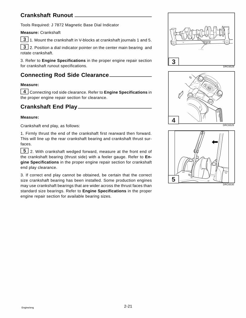
2-21Engine/eng
Crankshaft Runout
Tools Required: J 7872 Magnetic Base Dial Indicator
Measure: Crankshaft
3 1. Mount the crankshaft in V-blocks at crankshaft journals 1 and 5.
3 2. Position a dial indicator pointer on the center main bearing androtate crankshaft.
3. Refer to Engine Specifications in the proper engine repair sectionfor crankshaft runout specifications.
Connecting Rod Side Clearance
Measure:
4 Connecting rod side clearance. Refer to Engine Specifications inthe proper engine repair section for clearance.
Crankshaft End Play
Measure:
Crankshaft end play, as follows:
1. Firmly thrust the end of the crankshaft first rearward then forward.This will line up the rear crankshaft bearing and crankshaft thrust sur-faces.
5 2. With crankshaft wedged forward, measure at the front end ofthe crankshaft bearing (thrust side) with a feeler gauge. Refer to En-gine Specifications in the proper engine repair section for crankshaftend play clearance.
3. If correct end play cannot be obtained, be certain that the correctsize crankshaft bearing has been installed. Some production enginesmay use crankshaft bearings that are wider across the thrust faces thanstandard size bearings. Refer to Engine Specifications in the properengine repair section for available bearing sizes.
DRC6528
DRC6529
DRC6530
J 7872
3
4
5
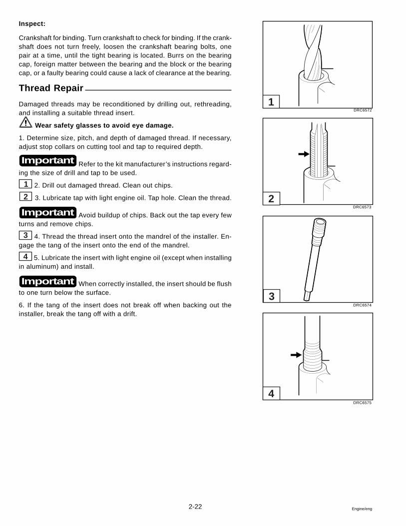
2-22 Engine/eng
Inspect:
Crankshaft for binding. Turn crankshaft to check for binding. If the crank-shaft does not turn freely, loosen the crankshaft bearing bolts, onepair at a time, until the tight bearing is located. Burrs on the bearingcap, foreign matter between the bearing and the block or the bearingcap, or a faulty bearing could cause a lack of clearance at the bearing.
Thread Repair
Damaged threads may be reconditioned by drilling out, rethreading,and installing a suitable thread insert.
Wear safety glasses to avoid eye damage.
1. Determine size, pitch, and depth of damaged thread. If necessary,adjust stop collars on cutting tool and tap to required depth.
Refer to the kit manufacturer’s instructions regard-ing the size of drill and tap to be used.
1 2. Drill out damaged thread. Clean out chips.
2 3. Lubricate tap with light engine oil. Tap hole. Clean the thread.
Avoid buildup of chips. Back out the tap every fewturns and remove chips.
3 4. Thread the thread insert onto the mandrel of the installer. En-gage the tang of the insert onto the end of the mandrel.
4 5. Lubricate the insert with light engine oil (except when installingin aluminum) and install.
When correctly installed, the insert should be flushto one turn below the surface.
6. If the tang of the insert does not break off when backing out theinstaller, break the tang off with a drift.
Important
Important
Important
DRC6572
DRC6573
DRC6574
DRC6575
1
2
3
4
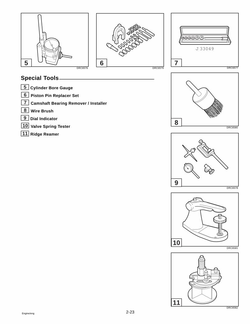
2-23Engine/eng
Special Tools
5 Cylinder Bore Gauge
6 Piston Pin Replacer Set
7 Camshaft Bearing Remover / Installer
8 Wire Brush
9 Dial Indicator
10 Valve Spring Tester
11 Ridge Reamer
DRC6576 DRC6579 DRC6577
DRC6580
DRC6578
DRC6581
DRC6582
11
10
9
8
765
J 33049

3-1Engine/eng
Section 33.0 GS Engines
Table of Contents
3
Camshaft ................................................................. 3-15Camshaft Bearings................................................. 3-17Circulating Pump.................................................... 3-33Connecting Rod Bearings ..................................... 3-20Crankshaft .............................................................. 3-19Crankshaft Bearings .............................................. 3-21Cylinder Block ........................................................ 3-28Cylinder Head ........................................................... 3-7Distributor Lower Bearing ..................................... 3-32Engine Coupler Replacement ................................ 3-38Engine Specifications ............................................ 3-40Exhaust Hose Replacement .................................. 3-37General Motors Tools ............................................... 3-2
High-Rise Exhaust Elbow Replacement ............... 3-36Hydaulic Valve Lifter ................................................ 3-4Intake/Exhaust Manifold .......................................... 3-3Oil Filter Bypass Valve ........................................... 3-36Oil Pan Replacement .............................................. 3-34Oil Pump ................................................................. 3-34Oil Seal Replacement, Rear Main Bearing ........... 3-24Oil Seal Retainer Replacement ............................. 3-24Piston Rings ........................................................... 3-26Piston and Connecting Rod .................................. 3-24Timing Gear Cover ................................................. 3-13Torque Specifications ............................................ 3-43Valve Lash Adjustment ............................................ 3-5Valve Spring and Seal Repair .................................. 3-6
Before removing cooling system hoses, it may be necessaryto remove boat from water to prevent flooding boat.
Safety Warnings
Before working on any part of the engine, read the Safety sectionat the end of this manual.
Unless instructed otherwise, always disconnect the battery cablesfrom the battery before working on electrical system to preventpossible sparks or arcing in the engine compartment.
Before starting engine after repair or maintenance procedures, al-ways make sure engine compartment is free of fuel vapors to pre-vent possible fire and explosion.
When working on an engine that is running or being cranked, useextreme care to avoid getting hands, fingers or clothing caught inthe alternator, power steering, supply pump and circulating pumpbelts, pulleys and other moving parts.
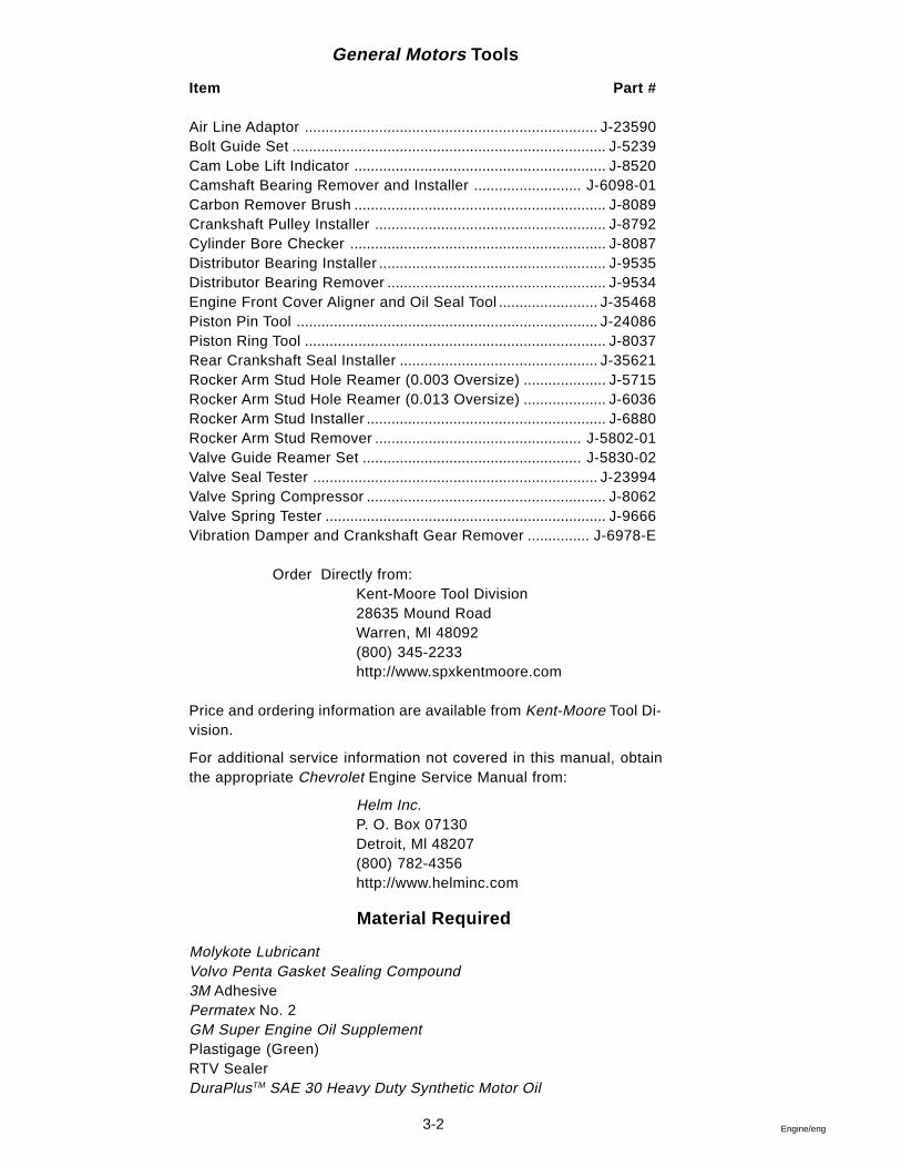
3-2 Engine/eng
General Motors Tools
Item Part #
Air Line Adaptor ....................................................................... J-23590Bolt Guide Set ............................................................................ J-5239Cam Lobe Lift Indicator ............................................................. J-8520Camshaft Bearing Remover and Installer .......................... J-6098-01Carbon Remover Brush ............................................................. J-8089Crankshaft Pulley Installer ........................................................ J-8792Cylinder Bore Checker .............................................................. J-8087Distributor Bearing Installer ....................................................... J-9535Distributor Bearing Remover ..................................................... J-9534Engine Front Cover Aligner and Oil Seal Tool ........................ J-35468Piston Pin Tool ......................................................................... J-24086Piston Ring Tool ......................................................................... J-8037Rear Crankshaft Seal Installer ................................................ J-35621Rocker Arm Stud Hole Reamer (0.003 Oversize) .................... J-5715Rocker Arm Stud Hole Reamer (0.013 Oversize) .................... J-6036Rocker Arm Stud Installer .......................................................... J-6880Rocker Arm Stud Remover .................................................. J-5802-01Valve Guide Reamer Set ..................................................... J-5830-02Valve Seal Tester ..................................................................... J-23994Valve Spring Compressor .......................................................... J-8062Valve Spring Tester .................................................................... J-9666Vibration Damper and Crankshaft Gear Remover ............... J-6978-E
Order Directly from:Kent-Moore Tool Division28635 Mound RoadWarren, Ml 48092(800) 345-2233http://www.spxkentmoore.com
Price and ordering information are available from Kent-Moore Tool Di-vision.
For additional service information not covered in this manual, obtainthe appropriate Chevrolet Engine Service Manual from:
Helm Inc.P. O. Box 07130Detroit, Ml 48207(800) 782-4356http://www.helminc.com
Material Required
Molykote LubricantVolvo Penta Gasket Sealing Compound3M AdhesivePermatex No. 2GM Super Engine Oil SupplementPlastigage (Green)RTV SealerDuraPlusTM SAE 30 Heavy Duty Synthetic Motor Oil
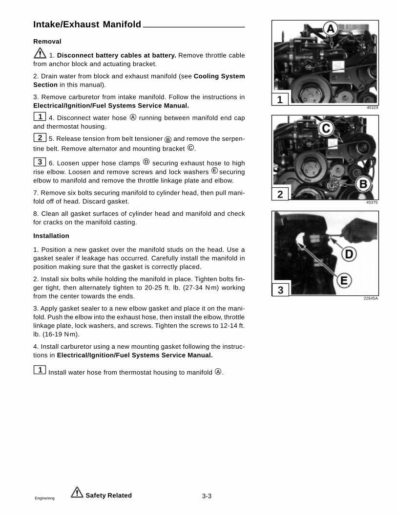
3-3Engine/eng
Intake/Exhaust Manifold
Removal
1. Disconnect battery cables at battery. Remove throttle cablefrom anchor block and actuating bracket.
2. Drain water from block and exhaust manifold (see Cooling SystemSection in this manual).
3. Remove carburetor from intake manifold. Follow the instructions inElectrical/Ignition/Fuel Systems Service Manual.
1 4. Disconnect water hose A running between manifold end capand thermostat housing.
2 5. Release tension from belt tensioner B and remove the serpen-
tine belt. Remove alternator and mounting bracket C .
3 6. Loosen upper hose clamps D securing exhaust hose to highrise elbow. Loosen and remove screws and lock washers E securingelbow to manifold and remove the throttle linkage plate and elbow.
7. Remove six bolts securing manifold to cylinder head, then pull mani-fold off of head. Discard gasket.
8. Clean all gasket surfaces of cylinder head and manifold and checkfor cracks on the manifold casting.
Installation
1. Position a new gasket over the manifold studs on the head. Use agasket sealer if leakage has occurred. Carefully install the manifold inposition making sure that the gasket is correctly placed.
2. Install six bolts while holding the manifold in place. Tighten bolts fin-ger tight, then alternately tighten to 20-25 ft. lb. (27-34 N•m) workingfrom the center towards the ends.
3. Apply gasket sealer to a new elbow gasket and place it on the mani-fold. Push the elbow into the exhaust hose, then install the elbow, throttlelinkage plate, lock washers, and screws. Tighten the screws to 12-14 ft.lb. (16-19 N•m).
4. Install carburetor using a new mounting gasket following the instruc-tions in Electrical/Ignition/Fuel Systems Service Manual.
1 Install water hose from thermostat housing to manifold A .
Safety Related
45329
45375
22645A
1
2
3
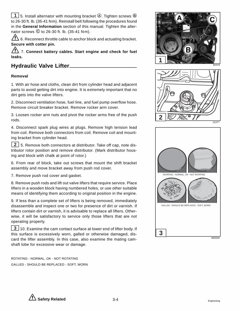
3-4 Engine/eng
1 5. Install alternator with mounting bracket A . Tighten screws B
to 26-30 ft. lb. (35-41 N•m). Reinstall belt following the procedures foundin the General Information section of this manual. Tighten the alter-nator screws C to 26-30 ft. lb. (35-41 N•m).
6. Reconnect throttle cable to anchor block and actuating bracket.Secure with cotter pin.
7. Connect battery cables. Start engine and check for fuelleaks.
Hydraulic Valve Lifter
Removal
1. With air hose and cloths, clean dirt from cylinder head and adjacentparts to avoid getting dirt into engine. It is extremely important that nodirt gets into the valve lifters.
2. Disconnect ventilation hose, fuel line, and fuel pump overflow hose.Remove circuit breaker bracket. Remove rocker arm cover.
3. Loosen rocker arm nuts and pivot the rocker arms free of the pushrods.
4. Disconnect spark plug wires at plugs. Remove high tension leadfrom coil. Remove both connectors from coil. Remove coil and mount-ing bracket from cylinder head.
2 5. Remove both connectors at distributor. Take off cap, note dis-tributor rotor position and remove distributor. (Mark distributor hous-ing and block with chalk at point of rotor.)
6. From rear of block, take out screws that mount the shift bracketassembly and move bracket away from push rod cover.
7. Remove push rod cover and gasket.
8. Remove push rods and lift out valve lifters that require service. Placelifters in a wooden block having numbered holes, or use other suitablemeans of identifying them according to original position in the engine.
9. If less than a complete set of lifters is being removed, immediatelydisassemble and inspect one or two for presence of dirt or varnish. Iflifters contain dirt or varnish, it is advisable to replace all lifters. Other-wise, it will be satisfactory to service only those lifters that are notoperating properly.
3 10. Examine the cam contact surface at lower end of lifter body. Ifthis surface is excessively worn, galled or otherwise damaged, dis-card the lifter assembly. In this case, also examine the mating cam-shaft lobe for excessive wear or damage.
ROTATING - NORMAL, OK - NOT ROTATING
GALLED - SHOULD BE REPLACED - SOFT, WORN
Safety Related
45376
22477
860000
3
2
1
ROTATING - NORMAL, OK - NOT ROTATING
GALLED - SHOULD BE REPLACED - SOFT, WORN
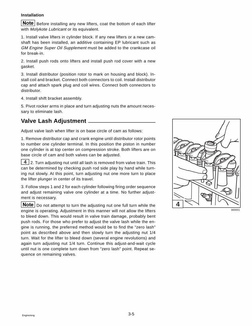
3-5Engine/eng
Installation
Before installing any new lifters, coat the bottom of each lifterwith Molykote Lubricant or its equivalent.
1. Install valve lifters in cylinder block. If any new lifters or a new cam-shaft has been installed, an additive containing EP lubricant such asGM Engine Super Oil Supplement must be added to the crankcase oilfor break-in.
2. Install push rods onto lifters and install push rod cover with a newgasket.
3. Install distributor (position rotor to mark on housing and block). In-stall coil and bracket. Connect both connectors to coil. Install distributorcap and attach spark plug and coil wires. Connect both connectors todistributor.
4. Install shift bracket assembly.
5. Pivot rocker arms in place and turn adjusting nuts the amount neces-sary to eliminate lash.
Valve Lash Adjustment
Adjust valve lash when lifter is on base circle of cam as follows:
1. Remove distributor cap and crank engine until distributor rotor pointsto number one cylinder terminal. In this position the piston in numberone cylinder is at top center on compression stroke. Both lifters are onbase circle of cam and both valves can be adjusted.
4 2. Turn adjusting nut until all lash is removed from valve train. Thiscan be determined by checking push rod side play by hand while turn-ing nut slowly. At this point, turn adjusting nut one more turn to placethe lifter plunger in center of its travel.
3. Follow steps 1 and 2 for each cylinder following firing order sequenceand adjust remaining valve one cylinder at a time. No further adjust-ment is necessary.
Do not attempt to turn the adjusting nut one full turn while theengine is operating. Adjustment in this manner will not allow the liftersto bleed down. This would result in valve train damage, probably bentpush rods. For those who prefer to adjust the valve lash while the en-gine is running, the preferred method would be to find the “zero lash”point as described above and then slowly turn the adjusting nut 1/4turn. Wait for the lifter to bleed down (several engine revolutions) andagain turn adjusting nut 1/4 turn. Continue this adjust-and-wait cycleuntil nut is one complete turn down from “zero lash” point. Repeat se-quence on remaining valves.
860001
4
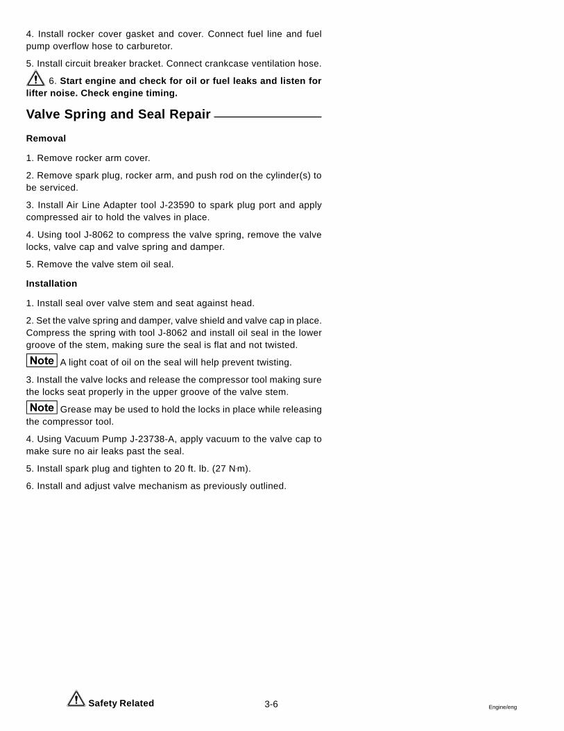
3-6 Engine/eng
4. Install rocker cover gasket and cover. Connect fuel line and fuelpump overflow hose to carburetor.
5. Install circuit breaker bracket. Connect crankcase ventilation hose.
6. Start engine and check for oil or fuel leaks and listen forlifter noise. Check engine timing.
Valve Spring and Seal Repair
Removal
1. Remove rocker arm cover.
2. Remove spark plug, rocker arm, and push rod on the cylinder(s) tobe serviced.
3. Install Air Line Adapter tool J-23590 to spark plug port and applycompressed air to hold the valves in place.
4. Using tool J-8062 to compress the valve spring, remove the valvelocks, valve cap and valve spring and damper.
5. Remove the valve stem oil seal.
Installation
1. Install seal over valve stem and seat against head.
2. Set the valve spring and damper, valve shield and valve cap in place.Compress the spring with tool J-8062 and install oil seal in the lowergroove of the stem, making sure the seal is flat and not twisted.
A light coat of oil on the seal will help prevent twisting.
3. Install the valve locks and release the compressor tool making surethe locks seat properly in the upper groove of the valve stem.
Grease may be used to hold the locks in place while releasingthe compressor tool.
4. Using Vacuum Pump J-23738-A, apply vacuum to the valve cap tomake sure no air leaks past the seal.
5. Install spark plug and tighten to 20 ft. lb. (27 N•m).
6. Install and adjust valve mechanism as previously outlined.
Safety Related
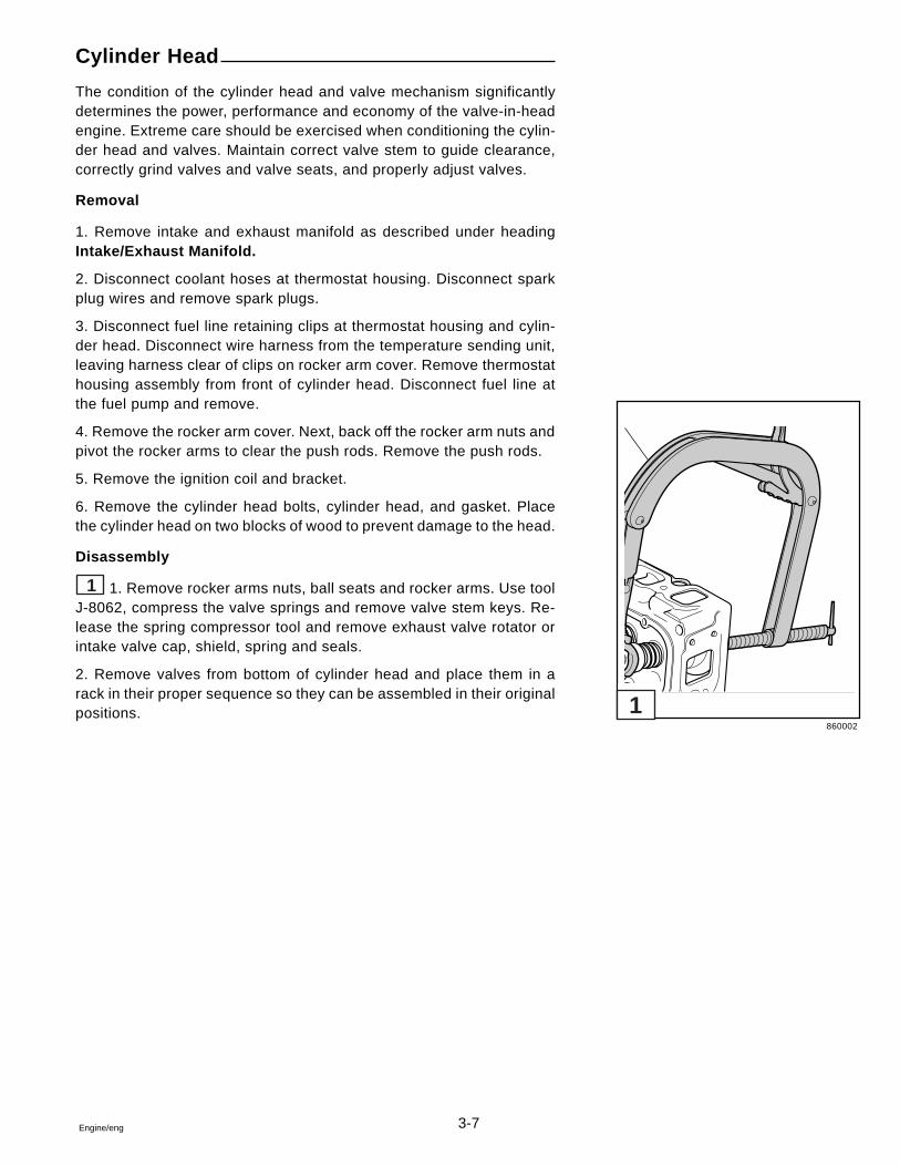
3-7Engine/eng
Cylinder Head
The condition of the cylinder head and valve mechanism significantlydetermines the power, performance and economy of the valve-in-headengine. Extreme care should be exercised when conditioning the cylin-der head and valves. Maintain correct valve stem to guide clearance,correctly grind valves and valve seats, and properly adjust valves.
Removal
1. Remove intake and exhaust manifold as described under headingIntake/Exhaust Manifold.
2. Disconnect coolant hoses at thermostat housing. Disconnect sparkplug wires and remove spark plugs.
3. Disconnect fuel line retaining clips at thermostat housing and cylin-der head. Disconnect wire harness from the temperature sending unit,leaving harness clear of clips on rocker arm cover. Remove thermostathousing assembly from front of cylinder head. Disconnect fuel line atthe fuel pump and remove.
4. Remove the rocker arm cover. Next, back off the rocker arm nuts andpivot the rocker arms to clear the push rods. Remove the push rods.
5. Remove the ignition coil and bracket.
6. Remove the cylinder head bolts, cylinder head, and gasket. Placethe cylinder head on two blocks of wood to prevent damage to the head.
Disassembly
1 1. Remove rocker arms nuts, ball seats and rocker arms. Use toolJ-8062, compress the valve springs and remove valve stem keys. Re-lease the spring compressor tool and remove exhaust valve rotator orintake valve cap, shield, spring and seals.
2. Remove valves from bottom of cylinder head and place them in arack in their proper sequence so they can be assembled in their originalpositions.
860002
1
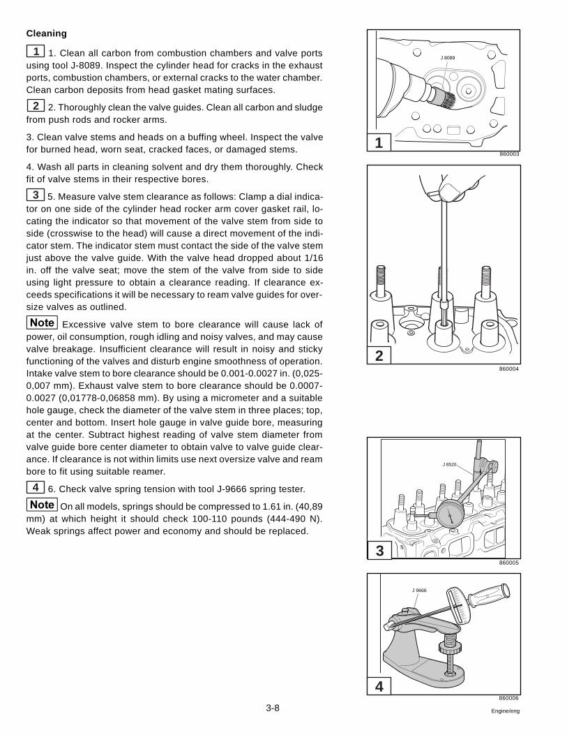
3-8 Engine/eng
Cleaning
1 1. Clean all carbon from combustion chambers and valve portsusing tool J-8089. Inspect the cylinder head for cracks in the exhaustports, combustion chambers, or external cracks to the water chamber.Clean carbon deposits from head gasket mating surfaces.
2 2. Thoroughly clean the valve guides. Clean all carbon and sludgefrom push rods and rocker arms.
3. Clean valve stems and heads on a buffing wheel. Inspect the valvefor burned head, worn seat, cracked faces, or damaged stems.
4. Wash all parts in cleaning solvent and dry them thoroughly. Checkfit of valve stems in their respective bores.
3 5. Measure valve stem clearance as follows: Clamp a dial indica-tor on one side of the cylinder head rocker arm cover gasket rail, lo-cating the indicator so that movement of the valve stem from side toside (crosswise to the head) will cause a direct movement of the indi-cator stem. The indicator stem must contact the side of the valve stemjust above the valve guide. With the valve head dropped about 1/16in. off the valve seat; move the stem of the valve from side to sideusing light pressure to obtain a clearance reading. If clearance ex-ceeds specifications it will be necessary to ream valve guides for over-size valves as outlined.
Excessive valve stem to bore clearance will cause lack ofpower, oil consumption, rough idling and noisy valves, and may causevalve breakage. Insufficient clearance will result in noisy and stickyfunctioning of the valves and disturb engine smoothness of operation.Intake valve stem to bore clearance should be 0.001-0.0027 in. (0,025-0,007 mm). Exhaust valve stem to bore clearance should be 0.0007-0.0027 (0,01778-0,06858 mm). By using a micrometer and a suitablehole gauge, check the diameter of the valve stem in three places; top,center and bottom. Insert hole gauge in valve guide bore, measuringat the center. Subtract highest reading of valve stem diameter fromvalve guide bore center diameter to obtain valve to valve guide clear-ance. If clearance is not within limits use next oversize valve and reambore to fit using suitable reamer.
4 6. Check valve spring tension with tool J-9666 spring tester.
On all models, springs should be compressed to 1.61 in. (40,89mm) at which height it should check 100-110 pounds (444-490 N).Weak springs affect power and economy and should be replaced.
860003
860004
860005
860006
J 8089
J 8520
J 9666
4
3
2
1
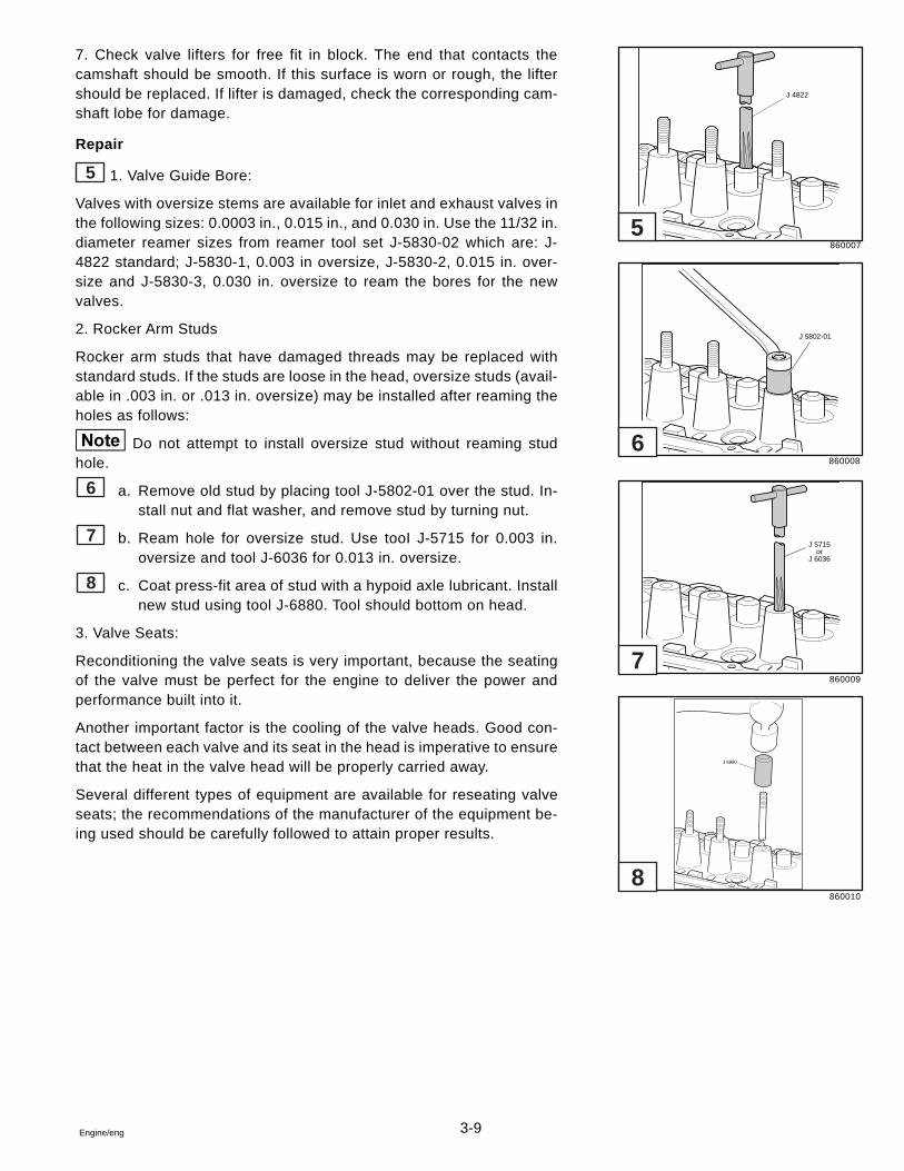
3-9Engine/eng
7. Check valve lifters for free fit in block. The end that contacts thecamshaft should be smooth. If this surface is worn or rough, the liftershould be replaced. If lifter is damaged, check the corresponding cam-shaft lobe for damage.
Repair
5 1. Valve Guide Bore:
Valves with oversize stems are available for inlet and exhaust valves inthe following sizes: 0.0003 in., 0.015 in., and 0.030 in. Use the 11/32 in.diameter reamer sizes from reamer tool set J-5830-02 which are: J-4822 standard; J-5830-1, 0.003 in oversize, J-5830-2, 0.015 in. over-size and J-5830-3, 0.030 in. oversize to ream the bores for the newvalves.
2. Rocker Arm Studs
Rocker arm studs that have damaged threads may be replaced withstandard studs. If the studs are loose in the head, oversize studs (avail-able in .003 in. or .013 in. oversize) may be installed after reaming theholes as follows:
Do not attempt to install oversize stud without reaming studhole.
6 a. Remove old stud by placing tool J-5802-01 over the stud. In-stall nut and flat washer, and remove stud by turning nut.
7 b. Ream hole for oversize stud. Use tooI J-5715 for 0.003 in.oversize and tool J-6036 for 0.013 in. oversize.
8 c. Coat press-fit area of stud with a hypoid axle lubricant. Installnew stud using tool J-6880. Tool should bottom on head.
3. Valve Seats:
Reconditioning the valve seats is very important, because the seatingof the valve must be perfect for the engine to deliver the power andperformance built into it.
Another important factor is the cooling of the valve heads. Good con-tact between each valve and its seat in the head is imperative to ensurethat the heat in the valve head will be properly carried away.
Several different types of equipment are available for reseating valveseats; the recommendations of the manufacturer of the equipment be-ing used should be carefully followed to attain proper results.
860007
860008
860009
860010
J 4822
J 5802-01
J 5715or
J 6036
J 6880
8
7
6
5
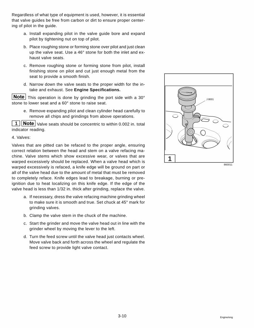
3-10 Engine/eng
Regardless of what type of equipment is used, however, it is essentialthat valve guides be free from carbon or dirt to ensure proper center-ing of pilot in the guide.
a. Install expanding pilot in the valve guide bore and expandpilot by tightening nut on top of pilot.
b. Place roughing stone or forming stone over pilot and just cleanup the valve seat. Use a 46° stone for both the inlet and ex-haust valve seats.
c. Remove roughing stone or forming stone from pilot, installfinishing stone on pilot and cut just enough metal from theseat to provide a smooth finish.
d. Narrow down the valve seats to the proper width for the in-take and exhaust. See Engine Specifications.
This operation is done by grinding the port side with a 30°stone to lower seat and a 60° stone to raise seat.
e. Remove expanding pilot and clean cylinder head carefully toremove all chips and grindings from above operations.
1 Valve seats should be concentric to within 0.002 in. totalindicator reading.
4. Valves:
Valves that are pitted can be refaced to the proper angle, ensuringcorrect relation between the head and stem on a valve refacing ma-chine. Valve stems which show excessive wear, or valves that arewarped excessively should be replaced. When a valve head which iswarped excessively is refaced, a knife edge will be ground on part orall of the valve head due to the amount of metal that must be removedto completely reface. Knife edges lead to breakage, burning or pre-ignition due to heat localizing on this knife edge. If the edge of thevalve head is less than 1/32 in. thick after grinding, replace the valve.
a. If necessary, dress the valve refacing machine grinding wheelto make sure it is smooth and true. Set chuck at 45° mark forgrinding valves.
b. Clamp the valve stem in the chuck of the machine.
c. Start the grinder and move the valve head out in line with thegrinder wheel by moving the lever to the left.
d. Turn the feed screw until the valve head just contacts wheel.Move valve back and forth across the wheel and regulate thefeed screw to provide light valve contact.
860011
J 8001
1
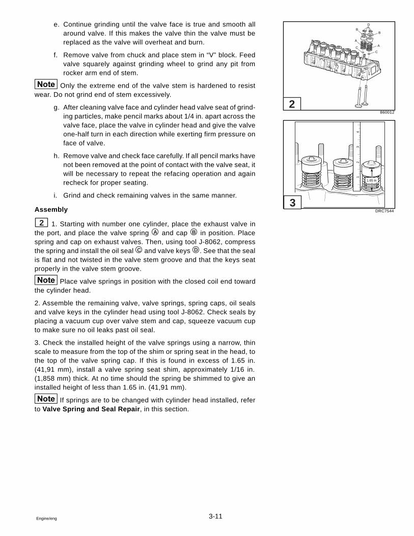
3-11Engine/eng
e. Continue grinding until the valve face is true and smooth allaround valve. If this makes the valve thin the valve must bereplaced as the valve will overheat and burn.
f. Remove valve from chuck and place stem in “V” block. Feedvalve squarely against grinding wheel to grind any pit fromrocker arm end of stem.
Only the extreme end of the valve stem is hardened to resistwear. Do not grind end of stem excessively.
g. After cleaning valve face and cylinder head valve seat of grind-ing particles, make pencil marks about 1/4 in. apart across thevalve face, place the valve in cylinder head and give the valveone-half turn in each direction while exerting firm pressure onface of valve.
h. Remove valve and check face carefully. If all pencil marks havenot been removed at the point of contact with the valve seat, itwill be necessary to repeat the refacing operation and againrecheck for proper seating.
i. Grind and check remaining valves in the same manner.
Assembly
2 1. Starting with number one cylinder, place the exhaust valve inthe port, and place the valve spring A and cap B in position. Placespring and cap on exhaust valves. Then, using tool J-8062, compressthe spring and install the oil seal C and valve keys D . See that the sealis flat and not twisted in the valve stem groove and that the keys seatproperly in the valve stem groove.
Place valve springs in position with the closed coil end towardthe cylinder head.
2. Assemble the remaining valve, valve springs, spring caps, oil sealsand valve keys in the cylinder head using tool J-8062. Check seals byplacing a vacuum cup over valve stem and cap, squeeze vacuum cupto make sure no oil leaks past oil seal.
3. Check the installed height of the valve springs using a narrow, thinscale to measure from the top of the shim or spring seat in the head, tothe top of the valve spring cap. If this is found in excess of 1.65 in.(41,91 mm), install a valve spring seat shim, approximately 1/16 in.(1,858 mm) thick. At no time should the spring be shimmed to give aninstalled height of less than 1.65 in. (41,91 mm).
If springs are to be changed with cylinder head installed, referto Valve Spring and Seal Repair , in this section.
860012
DRC7544
12
34
1.65 in
2
3
D
B
A
A
CC
B
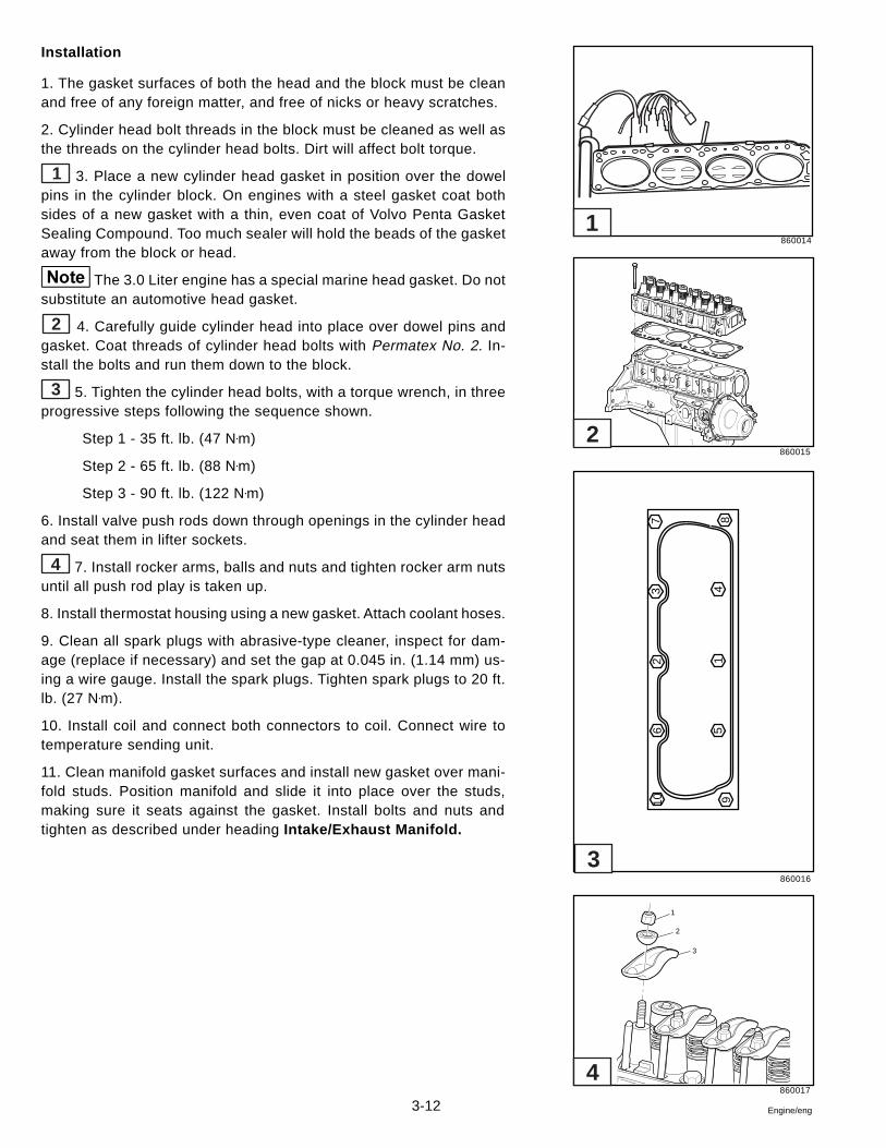
3-12 Engine/eng
Installation
1. The gasket surfaces of both the head and the block must be cleanand free of any foreign matter, and free of nicks or heavy scratches.
2. Cylinder head bolt threads in the block must be cleaned as well asthe threads on the cylinder head bolts. Dirt will affect bolt torque.
1 3. Place a new cylinder head gasket in position over the dowelpins in the cylinder block. On engines with a steel gasket coat bothsides of a new gasket with a thin, even coat of Volvo Penta GasketSealing Compound. Too much sealer will hold the beads of the gasketaway from the block or head.
The 3.0 Liter engine has a special marine head gasket. Do notsubstitute an automotive head gasket.
2 4. Carefully guide cylinder head into place over dowel pins andgasket. Coat threads of cylinder head bolts with Permatex No. 2. In-stall the bolts and run them down to the block.
3 5. Tighten the cylinder head bolts, with a torque wrench, in threeprogressive steps following the sequence shown.
Step 1 - 35 ft. lb. (47 N•m)
Step 2 - 65 ft. lb. (88 N•m)
Step 3 - 90 ft. lb. (122 N•m)
6. Install valve push rods down through openings in the cylinder headand seat them in lifter sockets.
4 7. Install rocker arms, balls and nuts and tighten rocker arm nutsuntil all push rod play is taken up.
8. Install thermostat housing using a new gasket. Attach coolant hoses.
9. Clean all spark plugs with abrasive-type cleaner, inspect for dam-age (replace if necessary) and set the gap at 0.045 in. (1.14 mm) us-ing a wire gauge. Install the spark plugs. Tighten spark plugs to 20 ft.lb. (27 N•m).
10. Install coil and connect both connectors to coil. Connect wire totemperature sending unit.
11. Clean manifold gasket surfaces and install new gasket over mani-fold studs. Position manifold and slide it into place over the studs,making sure it seats against the gasket. Install bolts and nuts andtighten as described under heading Intake/Exhaust Manifold.
860014
860015
860016
860017
1
2
3
4
3
2
1
106
23
7
9 5
14
8
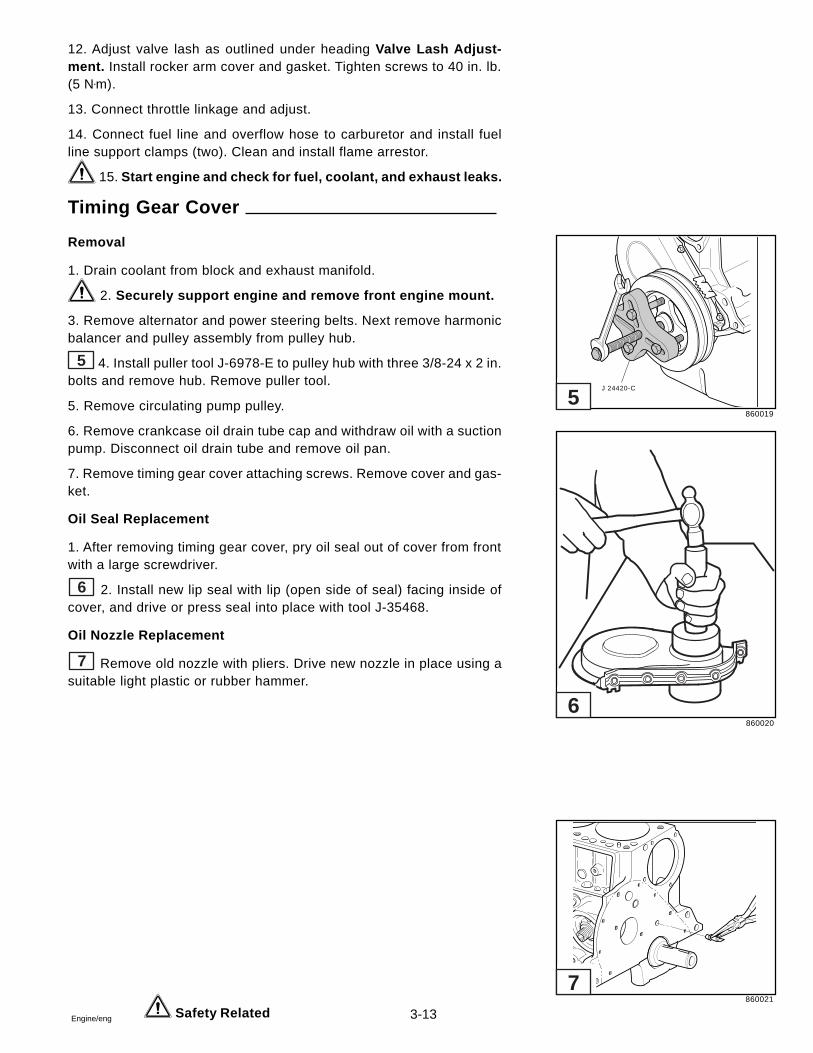
3-13Engine/eng
12. Adjust valve lash as outlined under heading Valve Lash Adjust-ment. Install rocker arm cover and gasket. Tighten screws to 40 in. lb.(5 N•m).
13. Connect throttle linkage and adjust.
14. Connect fuel line and overflow hose to carburetor and install fuelline support clamps (two). Clean and install flame arrestor.
15. Start engine and check for fuel, coolant, and exhaust leaks.
Timing Gear Cover
Removal
1. Drain coolant from block and exhaust manifold.
2. Securely support engine and remove front engine mount.
3. Remove alternator and power steering belts. Next remove harmonicbalancer and pulley assembly from pulley hub.
5 4. Install puller tool J-6978-E to pulley hub with three 3/8-24 x 2 in.bolts and remove hub. Remove puller tool.
5. Remove circulating pump pulley.
6. Remove crankcase oil drain tube cap and withdraw oil with a suctionpump. Disconnect oil drain tube and remove oil pan.
7. Remove timing gear cover attaching screws. Remove cover and gas-ket.
Oil Seal Replacement
1. After removing timing gear cover, pry oil seal out of cover from frontwith a large screwdriver.
6 2. Install new lip seal with lip (open side of seal) facing inside ofcover, and drive or press seal into place with tool J-35468.
Oil Nozzle Replacement
7 Remove old nozzle with pliers. Drive new nozzle in place using asuitable light plastic or rubber hammer.
Safety Related
860019
860020
860021
J 24420-C
7
6
5
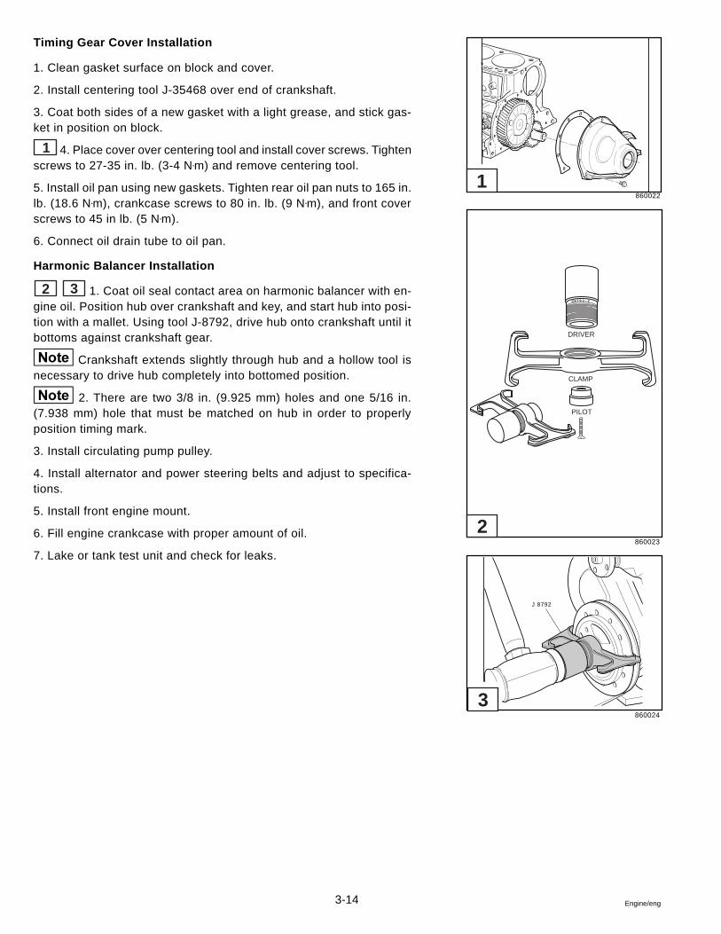
3-14 Engine/eng
Timing Gear Cover Installation
1. Clean gasket surface on block and cover.
2. Install centering tool J-35468 over end of crankshaft.
3. Coat both sides of a new gasket with a light grease, and stick gas-ket in position on block.
1 4. Place cover over centering tool and install cover screws. Tightenscrews to 27-35 in. lb. (3-4 N•m) and remove centering tool.
5. Install oil pan using new gaskets. Tighten rear oil pan nuts to 165 in.lb. (18.6 N•m), crankcase screws to 80 in. lb. (9 N•m), and front coverscrews to 45 in lb. (5 N•m).
6. Connect oil drain tube to oil pan.
Harmonic Balancer Installation
2 3 1. Coat oil seal contact area on harmonic balancer with en-gine oil. Position hub over crankshaft and key, and start hub into posi-tion with a mallet. Using tool J-8792, drive hub onto crankshaft until itbottoms against crankshaft gear.
Crankshaft extends slightly through hub and a hollow tool isnecessary to drive hub completely into bottomed position.
2. There are two 3/8 in. (9.925 mm) holes and one 5/16 in.(7.938 mm) hole that must be matched on hub in order to properlyposition timing mark.
3. Install circulating pump pulley.
4. Install alternator and power steering belts and adjust to specifica-tions.
5. Install front engine mount.
6. Fill engine crankcase with proper amount of oil.
7. Lake or tank test unit and check for leaks.
860022
860023
860024
J 8792
3
2
1
X8 7 9 2 2-
DRIVER
CLAMP
PILOT
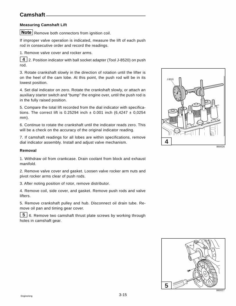
3-15Engine/eng
Camshaft
Measuring Camshaft Lift
Remove both connectors from ignition coil.
If improper valve operation is indicated, measure the lift of each pushrod in consecutive order and record the readings.
1. Remove valve cover and rocker arms.
4 2. Position indicator with ball socket adapter (Tool J-8520) on pushrod.
3. Rotate crankshaft slowly in the direction of rotation until the lifter ison the heel of the cam lobe. At this point, the push rod will be in itslowest position.
4. Set dial indicator on zero. Rotate the crankshaft slowly, or attach anauxiliary starter switch and “bump” the engine over, until the push rod isin the fully raised position.
5. Compare the total lift recorded from the dial indicator with specifica-tions. The correct lift is 0.25294 inch ± 0.001 inch (6,4247 ± 0,0254mm).
6. Continue to rotate the crankshaft until the indicator reads zero. Thiswill be a check on the accuracy of the original indicator reading.
7. If camshaft readings for all lobes are within specifications, removedial indicator assembly. Install and adjust valve mechanism.
Removal
1. Withdraw oil from crankcase. Drain coolant from block and exhaustmanifold.
2. Remove valve cover and gasket. Loosen valve rocker arm nuts andpivot rocker arms clear of push rods.
3. After noting position of rotor, remove distributor.
4. Remove coil, side cover, and gasket. Remove push rods and valvelifters.
5. Remove crankshaft pulley and hub. Disconnect oil drain tube. Re-move oil pan and timing gear cover.
5 6. Remove two camshaft thrust plate screws by working throughholes in camshaft gear.
860026
860027
J 8520
0
30
50
10
20
4060
70
80
90
5
4
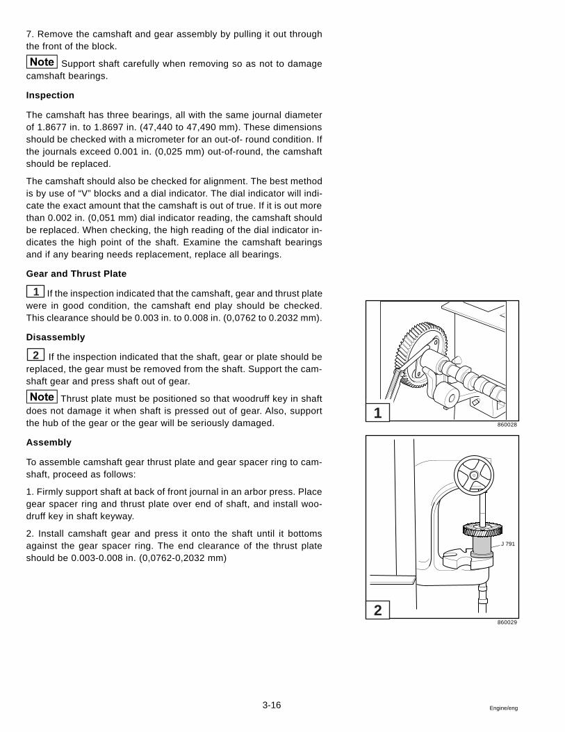
3-16 Engine/eng
J 791
7. Remove the camshaft and gear assembly by pulling it out throughthe front of the block.
Support shaft carefully when removing so as not to damagecamshaft bearings.
Inspection
The camshaft has three bearings, all with the same journal diameterof 1.8677 in. to 1.8697 in. (47,440 to 47,490 mm). These dimensionsshould be checked with a micrometer for an out-of- round condition. Ifthe journals exceed 0.001 in. (0,025 mm) out-of-round, the camshaftshould be replaced.
The camshaft should also be checked for alignment. The best methodis by use of “V” blocks and a dial indicator. The dial indicator will indi-cate the exact amount that the camshaft is out of true. If it is out morethan 0.002 in. (0,051 mm) dial indicator reading, the camshaft shouldbe replaced. When checking, the high reading of the dial indicator in-dicates the high point of the shaft. Examine the camshaft bearingsand if any bearing needs replacement, replace all bearings.
Gear and Thrust Plate
1 If the inspection indicated that the camshaft, gear and thrust platewere in good condition, the camshaft end play should be checked.This clearance should be 0.003 in. to 0.008 in. (0,0762 to 0.2032 mm).
Disassembly
2 If the inspection indicated that the shaft, gear or plate should bereplaced, the gear must be removed from the shaft. Support the cam-shaft gear and press shaft out of gear.
Thrust plate must be positioned so that woodruff key in shaftdoes not damage it when shaft is pressed out of gear. Also, supportthe hub of the gear or the gear will be seriously damaged.
Assembly
To assemble camshaft gear thrust plate and gear spacer ring to cam-shaft, proceed as follows:
1. Firmly support shaft at back of front journal in an arbor press. Placegear spacer ring and thrust plate over end of shaft, and install woo-druff key in shaft keyway.
2. Install camshaft gear and press it onto the shaft until it bottomsagainst the gear spacer ring. The end clearance of the thrust plateshould be 0.003-0.008 in. (0,0762-0,2032 mm)
860028
860029
1
2
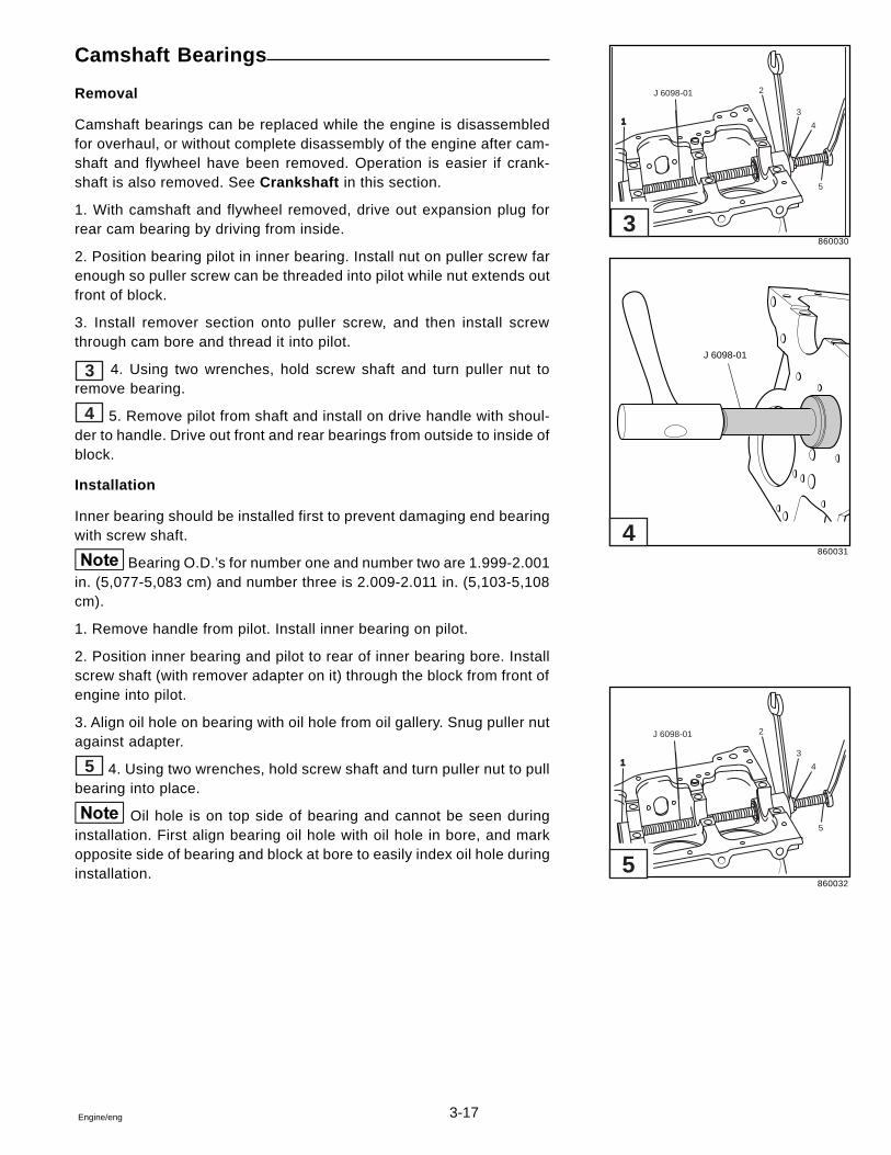
3-17Engine/eng
J 6098-01
11
2
3
4
5
Camshaft Bearings
Removal
Camshaft bearings can be replaced while the engine is disassembledfor overhaul, or without complete disassembly of the engine after cam-shaft and flywheel have been removed. Operation is easier if crank-shaft is also removed. See Crankshaft in this section.
1. With camshaft and flywheel removed, drive out expansion plug forrear cam bearing by driving from inside.
2. Position bearing pilot in inner bearing. Install nut on puller screw farenough so puller screw can be threaded into pilot while nut extends outfront of block.
3. Install remover section onto puller screw, and then install screwthrough cam bore and thread it into pilot.
3 4. Using two wrenches, hold screw shaft and turn puller nut toremove bearing.
4 5. Remove pilot from shaft and install on drive handle with shoul-der to handle. Drive out front and rear bearings from outside to inside ofblock.
Installation
Inner bearing should be installed first to prevent damaging end bearingwith screw shaft.
Bearing O.D.’s for number one and number two are 1.999-2.001in. (5,077-5,083 cm) and number three is 2.009-2.011 in. (5,103-5,108cm).
1. Remove handle from pilot. Install inner bearing on pilot.
2. Position inner bearing and pilot to rear of inner bearing bore. Installscrew shaft (with remover adapter on it) through the block from front ofengine into pilot.
3. Align oil hole on bearing with oil hole from oil gallery. Snug puller nutagainst adapter.
5 4. Using two wrenches, hold screw shaft and turn puller nut to pullbearing into place.
Oil hole is on top side of bearing and cannot be seen duringinstallation. First align bearing oil hole with oil hole in bore, and markopposite side of bearing and block at bore to easily index oil hole duringinstallation.
860030
860031
860032
J 6098-01
11
2
3
4
5
J 6098-01
5
4
3
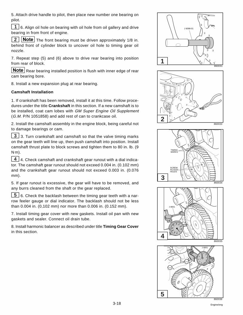
3-18 Engine/eng
5. Attach drive handle to pilot, then place new number one bearing onpilot.
1 6. Align oil hole on bearing with oil hole from oil gallery and drivebearing in from front of engine.
2 The front bearing must be driven approximately 1/8 in.behind front of cylinder block to uncover oil hole to timing gear oilnozzle.
7. Repeat step (5) and (6) above to drive rear bearing into positionfrom rear of block.
Rear bearing installed position is flush with inner edge of rearcam bearing bore.
8. Install a new expansion plug at rear bearing.
Camshaft Installation
1. If crankshaft has been removed, install it at this time. Follow proce-dures under the title Crankshaft in this section. If a new camshaft is tobe installed, coat cam lobes with GM Super Engine Oil Supplement(G.M. P/N 1051858) and add rest of can to crankcase oil.
2. Install the camshaft assembly in the engine block, being careful notto damage bearings or cam.
3 3. Turn crankshaft and camshaft so that the valve timing markson the gear teeth will line up, then push camshaft into position. Installcamshaft thrust plate to block screws and tighten them to 80 in. lb. (9N.m).
4 4. Check camshaft and crankshaft gear runout with a dial indica-tor. The camshaft gear runout should not exceed 0.004 in. (0.102 mm)and the crankshaft gear runout should not exceed 0.003 in. (0.076mm).
5. If gear runout is excessive, the gear will have to be removed, andany burrs cleaned from the shaft or the gear replaced.
5 6. Check the backlash between the timing gear teeth with a nar-row feeler gauge or dial indicator. The backlash should not be lessthan 0.004 in. (0,102 mm) nor more than 0.006 in. (0.152 mm).
7. Install timing gear cover with new gaskets. Install oil pan with newgaskets and sealer. Connect oil drain tube.
8. Install harmonic balancer as described under title Timing Gear Coverin this section.
860031
860033
860034
860035
860036
J 6098-01
TIMINGMARKS
SCREWACCESSHOLES
010
20
30
40
5060 70
80
90
J 8001
0 10
20
30
40
5060
70
80
90
J 8001
1
5
4
3
2
3-19Engine/eng
9. Install valve lifters and push rods. Install side cover with a new gas-ket and sealer. Attach coil and wires. Install distributor, positioning rotorto reference mark.
10. Pivot rocker arms over push rods. Adjust valve lash as outlined un-der heading Valve Lash Adjustment.
11. Add oil to engine. Install the alternator and power steering belts,then adjust tension. Check and adjust timing.
Crankshaft
Removal and Installation
1. Remove main bearing caps and connecting rod caps and lift crank-shaft out of cylinder block. Push pistons to top of bores.
2. Inspect the crankshaft:
Main bearing journals are ground to 2.979-2.994 in. (58,3666-58,4047mm).
Crankpin journals are ground to 2.099-2.100 in. (53,315-53,340).
These dimensions should be checked with a micrometer for out-of-round,taper or undersize. If the journals exceed 0.001 in. (0,025 mm) out-of-round or taper, the crankshaft should be replaced or reconditioned toan undersize figure that will enable the installation of undersize preci-sion type bearings.
The crankshaft should also be checked for runout. To perform this op-eration, support the crankshaft at the front and rear main bearing jour-nals in “V” blocks, and indicate the runout of both the front center andrear center journals using a dial indicator. The runout limit of each ofthese journals is 0.002 in. (0,051 mm). If the runout exceeds 0.002 in.(0,051 mm), the crankshaft must be repaired or replaced.
3. Remove rear main bearing oil seal.
4. Remove old bearings from cylinder block and caps. Install new bear-ings in the cylinder block and caps.
Main bearings with oil holes are the upper halves of the bear-ings and are inserted between the crankshaft and cylinder block.
5. Oil crankshaft journals and carefully place the crankshaft in the bear-ings.
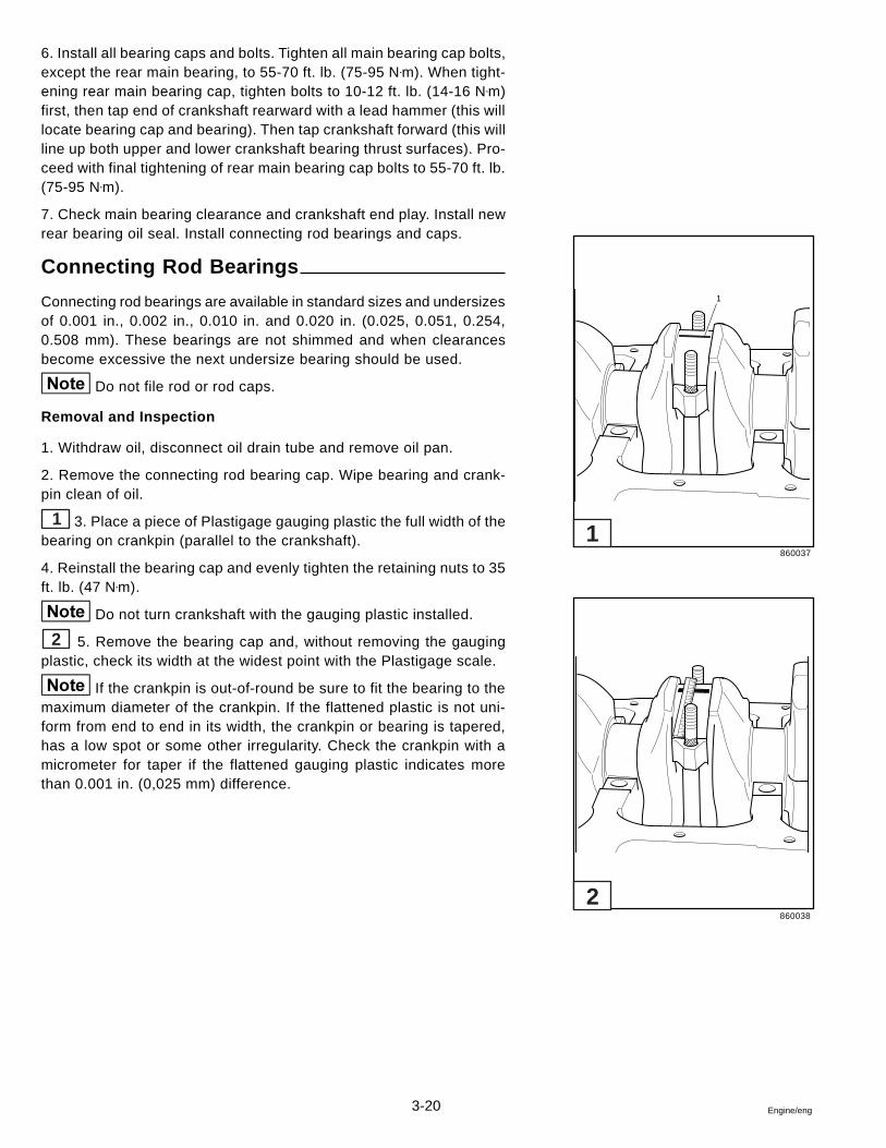
3-20 Engine/eng
6. Install all bearing caps and bolts. Tighten all main bearing cap bolts,except the rear main bearing, to 55-70 ft. lb. (75-95 N•m). When tight-ening rear main bearing cap, tighten bolts to 10-12 ft. lb. (14-16 N•m)first, then tap end of crankshaft rearward with a lead hammer (this willlocate bearing cap and bearing). Then tap crankshaft forward (this willline up both upper and lower crankshaft bearing thrust surfaces). Pro-ceed with final tightening of rear main bearing cap bolts to 55-70 ft. lb.(75-95 N•m).
7. Check main bearing clearance and crankshaft end play. Install newrear bearing oil seal. Install connecting rod bearings and caps.
Connecting Rod Bearings
Connecting rod bearings are available in standard sizes and undersizesof 0.001 in., 0.002 in., 0.010 in. and 0.020 in. (0.025, 0.051, 0.254,0.508 mm). These bearings are not shimmed and when clearancesbecome excessive the next undersize bearing should be used.
Do not file rod or rod caps.
Removal and Inspection
1. Withdraw oil, disconnect oil drain tube and remove oil pan.
2. Remove the connecting rod bearing cap. Wipe bearing and crank-pin clean of oil.
1 3. Place a piece of Plastigage gauging plastic the full width of thebearing on crankpin (parallel to the crankshaft).
4. Reinstall the bearing cap and evenly tighten the retaining nuts to 35ft. lb. (47 N•m).
Do not turn crankshaft with the gauging plastic installed.
2 5. Remove the bearing cap and, without removing the gaugingplastic, check its width at the widest point with the Plastigage scale.
If the crankpin is out-of-round be sure to fit the bearing to themaximum diameter of the crankpin. If the flattened plastic is not uni-form from end to end in its width, the crankpin or bearing is tapered,has a low spot or some other irregularity. Check the crankpin with amicrometer for taper if the flattened gauging plastic indicates morethan 0.001 in. (0,025 mm) difference.
860037
860038
1
1
2
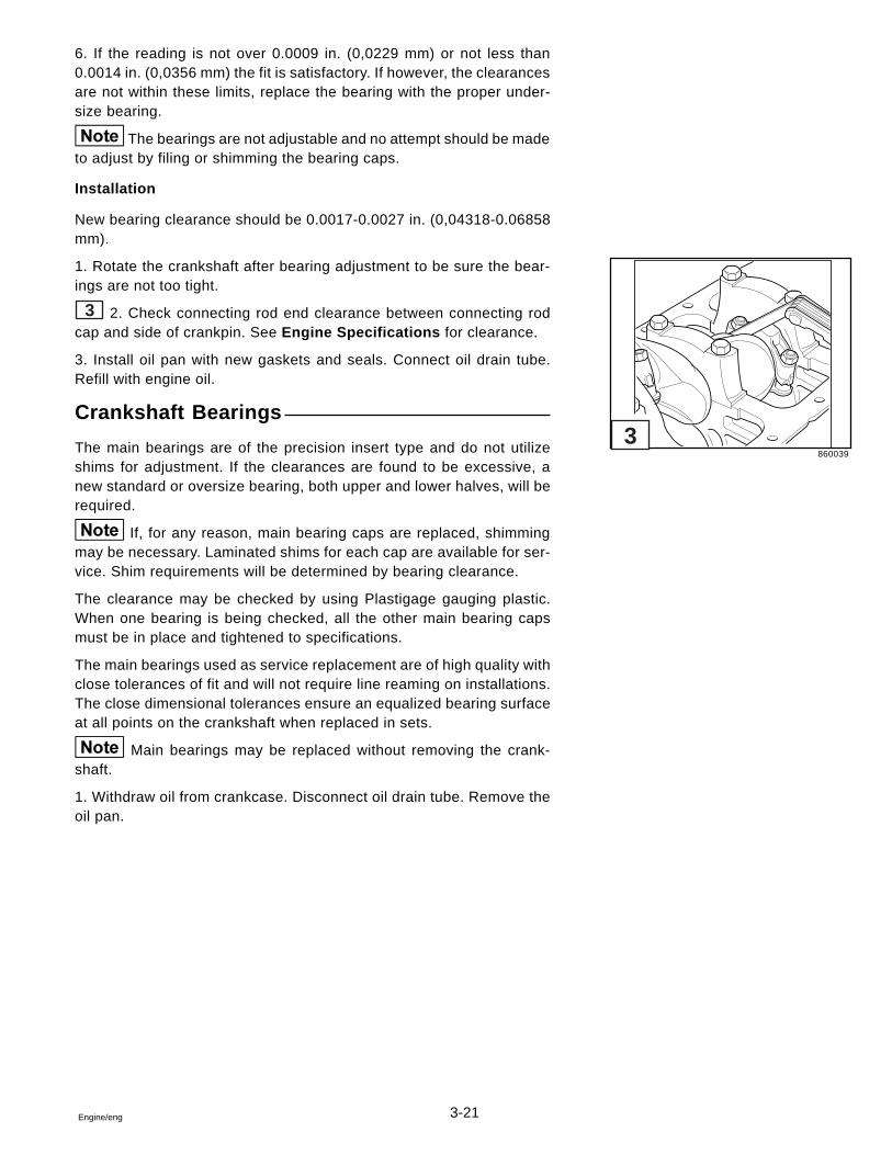
3-21Engine/eng
6. If the reading is not over 0.0009 in. (0,0229 mm) or not less than0.0014 in. (0,0356 mm) the fit is satisfactory. If however, the clearancesare not within these limits, replace the bearing with the proper under-size bearing.
The bearings are not adjustable and no attempt should be madeto adjust by filing or shimming the bearing caps.
Installation
New bearing clearance should be 0.0017-0.0027 in. (0,04318-0.06858mm).
1. Rotate the crankshaft after bearing adjustment to be sure the bear-ings are not too tight.
3 2. Check connecting rod end clearance between connecting rodcap and side of crankpin. See Engine Specifications for clearance.
3. Install oil pan with new gaskets and seals. Connect oil drain tube.Refill with engine oil.
Crankshaft Bearings
The main bearings are of the precision insert type and do not utilizeshims for adjustment. If the clearances are found to be excessive, anew standard or oversize bearing, both upper and lower halves, will berequired.
If, for any reason, main bearing caps are replaced, shimmingmay be necessary. Laminated shims for each cap are available for ser-vice. Shim requirements will be determined by bearing clearance.
The clearance may be checked by using Plastigage gauging plastic.When one bearing is being checked, all the other main bearing capsmust be in place and tightened to specifications.
The main bearings used as service replacement are of high quality withclose tolerances of fit and will not require line reaming on installations.The close dimensional tolerances ensure an equalized bearing surfaceat all points on the crankshaft when replaced in sets.
Main bearings may be replaced without removing the crank-shaft.
1. Withdraw oil from crankcase. Disconnect oil drain tube. Remove theoil pan.
860039
3
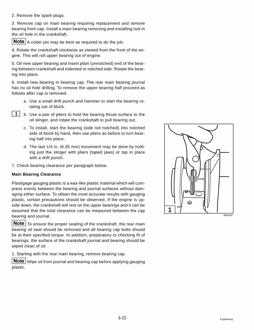
3-22 Engine/eng
2. Remove the spark plugs.
3. Remove cap on main bearing requiring replacement and removebearing from cap. Install a main bearing removing and installing tool inthe oil hole in the crankshaft.
A cotter pin may be bent as required to do the job.
4. Rotate the crankshaft clockwise as viewed from the front of the en-gine. This will roll upper bearing out of engine.
5. Oil new upper bearing and insert plain (unnotched) end of the bear-ing between crankshaft and indented or notched side. Rotate the bear-ing into place.
6. Install new bearing in bearing cap. The rear main bearing journalhas no oil hole drilling. To remove the upper bearing half proceed asfollows after cap is removed:
a. Use a small drift punch and hammer to start the bearing ro-tating out of block.
1 b. Use a pair of pliers to hold the bearing thrust surface to theoil slinger, and rotate the crankshaft to pull bearing out.
c. To install, start the bearing (side not notched) into notchedside of block by hand, then use pliers as before to turn bear-ing half into place.
d. The last 1/4 in. (6,35 mm) movement may be done by hold-ing just the slinger with pliers (taped jaws) or tap in placewith a drift punch.
7. Check bearing clearance per paragraph below.
Main Bearing Clearance
Plastigage gauging plastic is a wax-like plastic material which will com-press evenly between the bearing and journal surfaces without dam-aging either surface. To obtain the most accurate results with gaugingplastic, certain precautions should be observed. If the engine is up-side down, the crankshaft will rest on the upper bearings and it can beassumed that the total clearance can be measured between the capbearing and journal.
To ensure the proper seating of the crankshaft, the rear mainbearing oil seal should be removed and all bearing cap bolts shouldbe at their specified torque. In addition, preparatory to checking fit ofbearings, the surface of the crankshaft journal and bearing should bewiped clean of oil.
1. Starting with the rear main bearing, remove bearing cap.
Wipe oil from journal and bearing cap before applying gaugingplastic.
860040
1
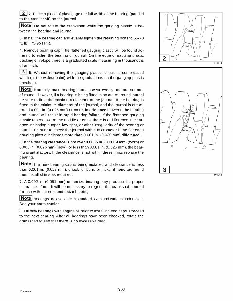
3-23Engine/eng
2 2. Place a piece of plastigage the full width of the bearing (parallelto the crankshaft) on the journal.
Do not rotate the crankshaft while the gauging plastic is be-tween the bearing and journal.
3. Install the bearing cap and evenly tighten the retaining bolts to 55-70ft. lb. (75-95 N•m).
4. Remove bearing cap. The flattened gauging plastic will be found ad-hering to either the bearing or journal. On the edge of gauging plasticpacking envelope there is a graduated scale measuring in thousandthsof an inch.
3 5. Without removing the gauging plastic, check its compressedwidth (at the widest point) with the graduations on the gauging plasticenvelope.
Normally, main bearing journals wear evenly and are not out-of-round. However, if a bearing is being fitted to an out-of- round journalbe sure to fit to the maximum diameter of the journal. If the bearing isfitted to the minimum diameter of the journal, and the journal is out-of-round 0.001 in. (0.025 mm) or more, interference between the bearingand journal will result in rapid bearing failure. If the flattened gaugingplastic tapers toward the middle or ends, there is a difference in clear-ance indicating a taper, low spot, or other irregularity of the bearing orjournal. Be sure to check the journal with a micrometer if the flattenedgauging plastic indicates more than 0.001 in. (0.025 mm) difference.
6. If the bearing clearance is not over 0.0035 in. (0.0889 mm) (worn) or0.003 in. (0.076 mm) (new), or less than 0.001 in. (0.025 mm), the bear-ing is satisfactory. If the clearance is not within these limits replace thebearing.
If a new bearing cap is being installed and clearance is lessthan 0.001 in. (0.025 mm), check for burrs or nicks; if none are foundthen install shims as required.
7. A 0.002 in. (0.051 mm) undersize bearing may produce the properclearance. If not, it will be necessary to regrind the crankshaft journalfor use with the next undersize bearing.
Bearings are available in standard sizes and various undersizes.See your parts catalog.
8. Oil new bearings with engine oil prior to installing end caps. Proceedto the next bearing. After all bearings have been checked, rotate thecrankshaft to see that there is no excessive drag.
860041
860042
1
2
3
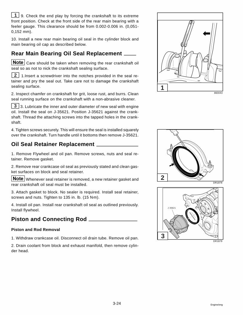
3-24 Engine/eng
1 9. Check the end play by forcing the crankshaft to its extremefront position. Check at the front side of the rear main bearing with afeeler gauge. This clearance should be from 0.002-0.006 in. (0,051-0,152 mm).
10. Install a new rear main bearing oil seal in the cylinder block andmain bearing oil cap as described below.
Rear Main Bearing Oil Seal Replacement
Care should be taken when removing the rear crankshaft oilseal so as not to nick the crankshaft sealing surface.
2 1.Insert a screwdriver into the notches provided in the seal re-tainer and pry the seal out. Take care not to damage the crankshaftsealing surface.
2. Inspect chamfer on crankshaft for grit, loose rust, and burrs. Cleanseal running surface on the crankshaft with a non-abrasive cleaner.
3 3. Lubricate the inner and outer diameter of new seal with engineoil. Install the seal on J-35621. Position J-35621 against the crank-shaft. Thread the attaching screws into the tapped holes in the crank-shaft.
4. Tighten screws securely. This will ensure the seal is installed squarelyover the crankshaft. Turn handle until it bottoms then remove J-35621.
Oil Seal Retainer Replacement
1. Remove Flywheel and oil pan. Remove screws, nuts and seal re-tainer. Remove gasket.
2. Remove rear crankcase oil seal as previously stated and clean gas-ket surfaces on block and seal retainer.
Whenever seal retainer is removed, a new retainer gasket andrear crankshaft oil seal must be installed.
3. Attach gasket to block. No sealer is required. Install seal retainer,screws and nuts. Tighten to 135 in. lb. (15 N•m).
4. Install oil pan. Install rear crankshaft oil seal as outlined previously.Install flywheel.
Piston and Connecting Rod
Piston and Rod Removal
1. Withdraw crankcase oil. Disconnect oil drain tube. Remove oil pan.
2. Drain coolant from block and exhaust manifold, then remove cylin-der head.
860043
DR1878
DR1879
J 35621
1
2
3
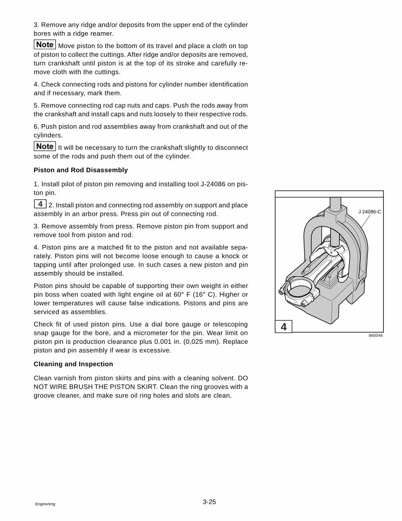
3-25Engine/eng
3. Remove any ridge and/or deposits from the upper end of the cylinderbores with a ridge reamer.
Move piston to the bottom of its travel and place a cloth on topof piston to collect the cuttings. After ridge and/or deposits are removed,turn crankshaft until piston is at the top of its stroke and carefully re-move cloth with the cuttings.
4. Check connecting rods and pistons for cylinder number identificationand if necessary, mark them.
5. Remove connecting rod cap nuts and caps. Push the rods away fromthe crankshaft and install caps and nuts loosely to their respective rods.
6. Push piston and rod assemblies away from crankshaft and out of thecylinders.
It will be necessary to turn the crankshaft slightly to disconnectsome of the rods and push them out of the cylinder.
Piston and Rod Disassembly
1. Install pilot of piston pin removing and installing tool J-24086 on pis-ton pin.
4 2. Install piston and connecting rod assembly on support and placeassembly in an arbor press. Press pin out of connecting rod.
3. Remove assembly from press. Remove piston pin from support andremove tool from piston and rod.
4. Piston pins are a matched fit to the piston and not available sepa-rately. Piston pins will not become loose enough to cause a knock ortapping until after prolonged use. In such cases a new piston and pinassembly should be installed.
Piston pins should be capable of supporting their own weight in eitherpin boss when coated with light engine oil at 60° F (16° C). Higher orlower temperatures will cause false indications. Pistons and pins areserviced as assemblies.
Check fit of used piston pins. Use a dial bore gauge or telescopingsnap gauge for the bore, and a micrometer for the pin. Wear limit onpiston pin is production clearance plus 0.001 in. (0,025 mm). Replacepiston and pin assembly if wear is excessive.
Cleaning and Inspection
Clean varnish from piston skirts and pins with a cleaning solvent. DONOT WIRE BRUSH THE PISTON SKIRT. Clean the ring grooves with agroove cleaner, and make sure oil ring holes and slots are clean.
860046
J 24086-C
4
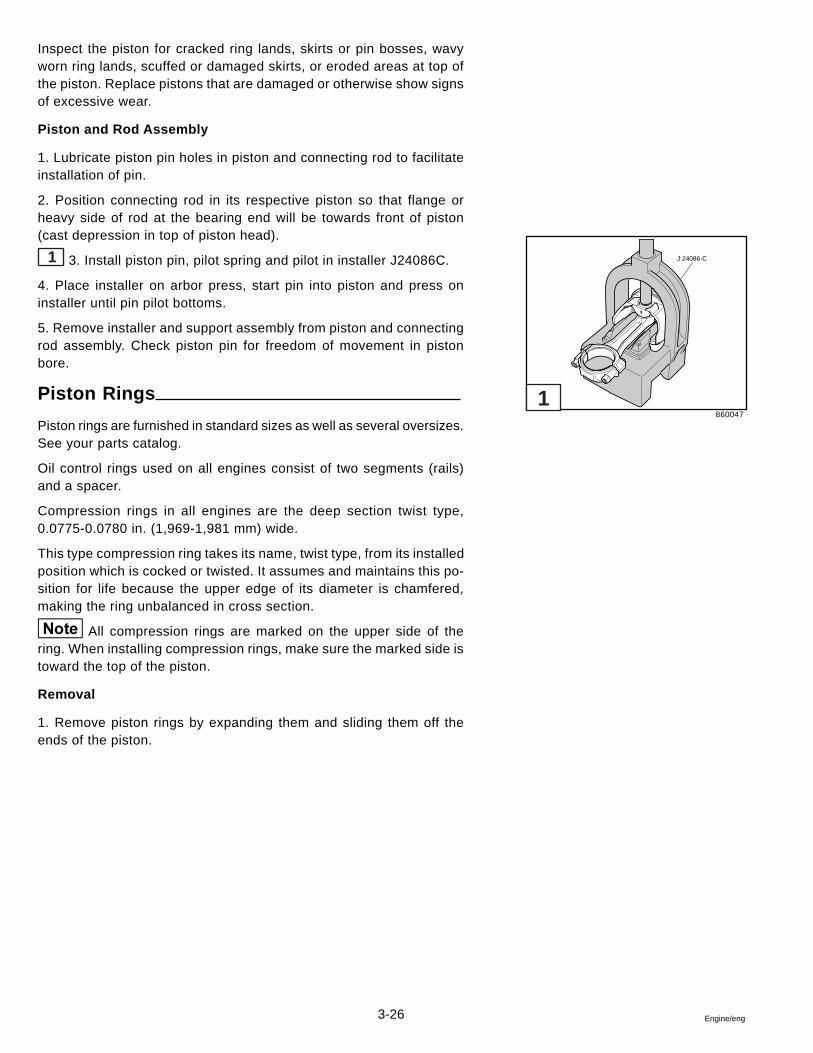
3-26 Engine/eng
Inspect the piston for cracked ring lands, skirts or pin bosses, wavyworn ring lands, scuffed or damaged skirts, or eroded areas at top ofthe piston. Replace pistons that are damaged or otherwise show signsof excessive wear.
Piston and Rod Assembly
1. Lubricate piston pin holes in piston and connecting rod to facilitateinstallation of pin.
2. Position connecting rod in its respective piston so that flange orheavy side of rod at the bearing end will be towards front of piston(cast depression in top of piston head).
1 3. Install piston pin, pilot spring and pilot in installer J24086C.
4. Place installer on arbor press, start pin into piston and press oninstaller until pin pilot bottoms.
5. Remove installer and support assembly from piston and connectingrod assembly. Check piston pin for freedom of movement in pistonbore.
Piston Rings
Piston rings are furnished in standard sizes as well as several oversizes.See your parts catalog.
Oil control rings used on all engines consist of two segments (rails)and a spacer.
Compression rings in all engines are the deep section twist type,0.0775-0.0780 in. (1,969-1,981 mm) wide.
This type compression ring takes its name, twist type, from its installedposition which is cocked or twisted. It assumes and maintains this po-sition for life because the upper edge of its diameter is chamfered,making the ring unbalanced in cross section.
All compression rings are marked on the upper side of thering. When installing compression rings, make sure the marked side istoward the top of the piston.
Removal
1. Remove piston rings by expanding them and sliding them off theends of the piston.
860047
1
J 24086-C
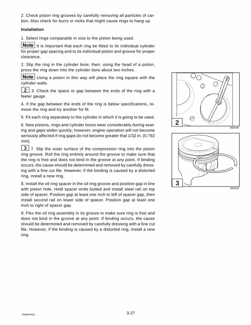
3-27Engine/eng
2. Check piston ring grooves by carefully removing all particles of car-bon. Also check for burrs or nicks that might cause rings to hang up.
Installation
1. Select rings comparable in size to the piston being used.
It is important that each ring be fitted to its individual cylinderfor proper gap spacing and to its individual piston and groove for properclearance.
2. Slip the ring in the cylinder bore; then, using the head of a piston,press the ring down into the cylinder bore about two inches.
Using a piston in this way will place the ring square with thecylinder walls.
2 3. Check the space or gap between the ends of the ring with afeeler gauge.
4. If the gap between the ends of the ring is below specifications, re-move the ring and try another for fit.
5. Fit each ring separately to the cylinder in which it is going to be used.
6. New pistons, rings and cylinder bores wear considerably during seat-ing and gaps widen quickly; however, engine operation will not becomeseriously affected if ring gaps do not become greater that 1/32 in. (0,792mm).
3 7. Slip the outer surface of the compression ring into the pistonring groove. Roll the ring entirely around the groove to make sure thatthe ring is free and does not bind in the groove at any point. If bindingoccurs, the cause should be determined and removed by carefully dress-ing with a fine cut file. However, if the binding is caused by a distortedring, install a new ring.
8. Install the oil ring spacer in the oil ring groove and position gap in linewith piston hole. Hold spacer ends butted and install steel rail on topside of spacer. Position gap at least one inch to left of spacer gap, theninstall second rail on lower side of spacer. Position gap at least oneinch to right of spacer gap.
9. Flex the oil ring assembly in its groove to make sure ring is free anddoes not bind in the groove at any point. If binding occurs, the causeshould be determined and removed by carefully dressing with a fine cutfile. However, if the binding is caused by a distorted ring, install a newring.
860048
860049
2
3
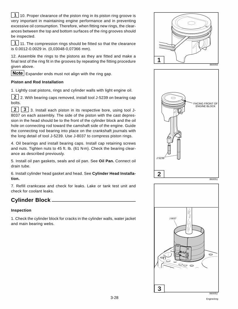
3-28 Engine/eng
1 10. Proper clearance of the piston ring in its piston ring groove isvery important in maintaining engine performance and in preventingexcessive oil consumption. Therefore, when fitting new rings, the clear-ances between the top and bottom surfaces of the ring grooves shouldbe inspected.
1 11. The compression rings should be fitted so that the clearanceis 0.0012-0.0029 in. (0,03048-0,07366 mm).
12. Assemble the rings to the pistons as they are fitted and make afinal test of the ring fit in the grooves by repeating the fitting proceduregiven above.
Expander ends must not align with the ring gap.
Piston and Rod Installation
1. Lightly coat pistons, rings and cylinder walls with light engine oil.
2 2. With bearing caps removed, install tool J-5239 on bearing capbolts.
2 3 3. Install each piston in its respective bore, using tool J-8037 on each assembly. The side of the piston with the cast depres-sion in the head should be to the front of the cylinder block and the oilhole on connecting rod toward the camshaft side of the engine. Guidethe connecting rod bearing into place on the crankshaft journals withthe long detail of tool J-5239. Use J-8037 to compress piston rings.
4. Oil bearings and install bearing caps. Install cap retaining screwsand nuts. Tighten nuts to 45 ft. lb. (61 N•m). Check the bearing clear-ance as described previously.
5. Install oil pan gaskets, seals and oil pan. See Oil Pan. Connect oildrain tube.
6. Install cylinder head gasket and head. See Cylinder Head Installa-tion.
7. Refill crankcase and check for leaks. Lake or tank test unit andcheck for coolant leaks.
Cylinder Block
Inspection
1. Check the cylinder block for cracks in the cylinder walls, water jacketand main bearing webs.
860050
860051
860052
FACING FRONT OFENGINE BLOCK
J 5239
J 8037
1
2
3
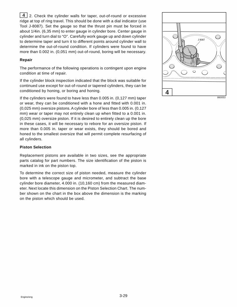
3-29Engine/eng
4 2. Check the cylinder walls for taper, out-of-round or excessiveridge at top of ring travel. This should be done with a dial indicator (useTool J-8087). Set the gauge so that the thrust pin must be forced inabout 1/4in. (6,35 mm) to enter gauge in cylinder bore. Center gauge incylinder and turn dial to “O”. Carefully work gauge up and down cylinderto determine taper and turn it to different points around cylinder wall todetermine the out-of-round condition. If cylinders were found to havemore than 0.002 in. (0,051 mm) out-of-round, boring will be necessary.
Repair
The performance of the following operations is contingent upon enginecondition at time of repair.
If the cylinder block inspection indicated that the block was suitable forcontinued use except for out-of-round or tapered cylinders, they can beconditioned by honing, or boring and honing.
If the cylinders were found to have less than 0.005 in. (0,127 mm) taperor wear, they can be conditioned with a hone and fitted with 0.001 in.(0,025 mm) oversize pistons. A cylinder bore of less than 0.005 in. (0,127mm) wear or taper may not entirely clean up when fitted to a 0.001 in.(0,025 mm) oversize piston. If it is desired to entirely clean up the borein these cases, it will be necessary to rebore for an oversize piston. Ifmore than 0.005 in. taper or wear exists, they should be bored andhoned to the smallest oversize that will permit complete resurfacing ofall cylinders.
Piston Selection
Replacement pistons are available in two sizes, see the appropriateparts catalog for part numbers. The size identification of the piston ismarked in ink on the piston top.
To determine the correct size of piston needed, measure the cylinderbore with a telescope gauge and micrometer, and subtract the basecylinder bore diameter, 4.000 in. (10,160 cm) from the measured diam-eter. Next locate this dimension on the Piston Selection Chart. The num-ber shown on the chart in the box above the dimension is the markingon the piston which should be used.
860053
J 8087
4
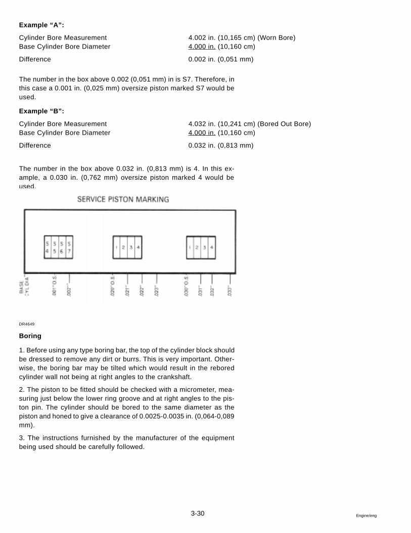
3-30 Engine/eng
Example “A”:
Cylinder Bore Measurement 4.002 in. (10,165 cm) (Worn Bore)Base Cylinder Bore Diameter 4.000 in. (10,160 cm)
Difference 0.002 in. (0,051 mm)
The number in the box above 0.002 (0,051 mm) in is S7. Therefore, inthis case a 0.001 in. (0,025 mm) oversize piston marked S7 would beused.
Example “B”:
Cylinder Bore Measurement 4.032 in. (10,241 cm) (Bored Out Bore)Base Cylinder Bore Diameter 4.000 in. (10,160 cm)
Difference 0.032 in. (0,813 mm)
The number in the box above 0.032 in. (0,813 mm) is 4. In this ex-ample, a 0.030 in. (0,762 mm) oversize piston marked 4 would beused.
DR4649
Boring
1. Before using any type boring bar, the top of the cylinder block shouldbe dressed to remove any dirt or burrs. This is very important. Other-wise, the boring bar may be tilted which would result in the reboredcylinder wall not being at right angles to the crankshaft.
2. The piston to be fitted should be checked with a micrometer, mea-suring just below the lower ring groove and at right angles to the pis-ton pin. The cylinder should be bored to the same diameter as thepiston and honed to give a clearance of 0.0025-0.0035 in. (0,064-0,089mm).
3. The instructions furnished by the manufacturer of the equipmentbeing used should be carefully followed.
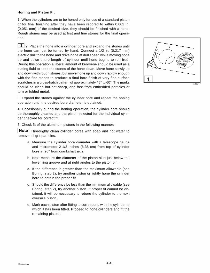
3-31Engine/eng
Honing and Piston Fit
1. When the cylinders are to be honed only for use of a standard pistonor for final finishing after they have been rebored to within 0.002 in.(0,051 mm) of the desired size, they should be finished with a hone.Rough stones may be used at first and fine stones for the final opera-tion.
1 2. Place the hone into a cylinder bore and expand the stones untilthe hone can just be turned by hand. Connect a 1/2 in. (0,217 mm)electric drill to the hone and drive hone at drill speed while moving honeup and down entire length of cylinder until hone begins to run free.During this operation a liberal amount of kerosene should be used as acutting fluid to keep the stones of the hone clean. Move hone slowly upand down with rough stones, but move hone up and down rapidly enoughwith the fine stones to produce a final bore finish of very fine surfacescratches in a cross-hatch pattern of approximately 45° to 60°. The marksshould be clean but not sharp, and free from embedded particles ortorn or folded metal.
3. Expand the stones against the cylinder bore and repeat the honingoperation until the desired bore diameter is obtained.
4. Occasionally during the honing operation, the cylinder bore shouldbe thoroughly cleaned and the piston selected for the individual cylin-der checked for correct fit.
5. Check fit of the aluminum pistons in the following manner:
Thoroughly clean cylinder bores with soap and hot water toremove all grit particles.
a. Measure the cylinder bore diameter with a telescope gaugeand micrometer 2-1/2 inches (6,35 cm) from top of cylinderbore at 90° from crankshaft axis.
b. Next measure the diameter of the piston skirt just below thelower ring groove and at right angles to the piston pin.
c. If the difference is greater than the maximum allowable (seeBoring, step 2), try another piston or lightly hone the cylinderbore to obtain the proper fit.
d. Should the difference be less than the minimum allowable (seeBoring, step 2), try another piston. If proper fit cannot be ob-tained, it will be necessary to rebore the cylinder to the nextoversize piston.
e. Mark each piston after fitting to correspond with the cylinder towhich it has been fitted. Proceed to hone cylinders and fit theremaining pistons.
1186747
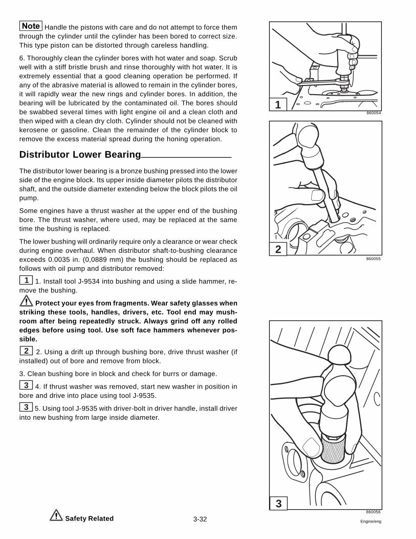
3-32 Engine/eng
Handle the pistons with care and do not attempt to force themthrough the cylinder until the cylinder has been bored to correct size.This type piston can be distorted through careless handling.
6. Thoroughly clean the cylinder bores with hot water and soap. Scrubwell with a stiff bristle brush and rinse thoroughly with hot water. It isextremely essential that a good cleaning operation be performed. Ifany of the abrasive material is allowed to remain in the cylinder bores,it will rapidly wear the new rings and cylinder bores. In addition, thebearing will be lubricated by the contaminated oil. The bores shouldbe swabbed several times with light engine oil and a clean cloth andthen wiped with a clean dry cloth. Cylinder should not be cleaned withkerosene or gasoline. Clean the remainder of the cylinder block toremove the excess material spread during the honing operation.
Distributor Lower Bearing
The distributor lower bearing is a bronze bushing pressed into the lowerside of the engine block. Its upper inside diameter pilots the distributorshaft, and the outside diameter extending below the block pilots the oilpump.
Some engines have a thrust washer at the upper end of the bushingbore. The thrust washer, where used, may be replaced at the sametime the bushing is replaced.
The lower bushing will ordinarily require only a clearance or wear checkduring engine overhaul. When distributor shaft-to-bushing clearanceexceeds 0.0035 in. (0,0889 mm) the bushing should be replaced asfollows with oil pump and distributor removed:
1 1. Install tool J-9534 into bushing and using a slide hammer, re-move the bushing.
Protect your eyes from fragments. Wear safety glasses whenstriking these tools, handles, drivers, etc. Tool end may mush-room after being repeatedly struck. Always grind off any rollededges before using tool. Use soft face hammers whenever pos-sible.
2 2. Using a drift up through bushing bore, drive thrust washer (ifinstalled) out of bore and remove from block.
3. Clean bushing bore in block and check for burrs or damage.
3 4. If thrust washer was removed, start new washer in position inbore and drive into place using tool J-9535.
3 5. Using tool J-9535 with driver-bolt in driver handle, install driverinto new bushing from large inside diameter.
Safety Related
860054
860055
860056
1
2
3
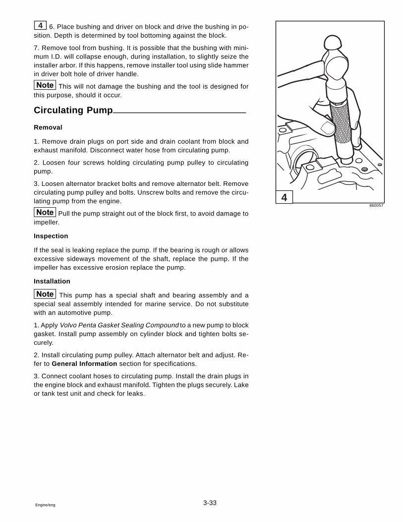
3-33Engine/eng
4 6. Place bushing and driver on block and drive the bushing in po-sition. Depth is determined by tool bottoming against the block.
7. Remove tool from bushing. It is possible that the bushing with mini-mum I.D. will collapse enough, during installation, to slightly seize theinstaller arbor. If this happens, remove installer tool using slide hammerin driver bolt hole of driver handle.
This will not damage the bushing and the tool is designed forthis purpose, should it occur.
Circulating Pump
Removal
1. Remove drain plugs on port side and drain coolant from block andexhaust manifold. Disconnect water hose from circulating pump.
2. Loosen four screws holding circulating pump pulley to circulatingpump.
3. Loosen alternator bracket bolts and remove alternator belt. Removecirculating pump pulley and bolts. Unscrew bolts and remove the circu-lating pump from the engine.
Pull the pump straight out of the block first, to avoid damage toimpeller.
Inspection
If the seal is leaking replace the pump. If the bearing is rough or allowsexcessive sideways movement of the shaft, replace the pump. If theimpeller has excessive erosion replace the pump.
Installation
This pump has a special shaft and bearing assembly and aspecial seal assembly intended for marine service. Do not substitutewith an automotive pump.
1. Apply Volvo Penta Gasket Sealing Compound to a new pump to blockgasket. Install pump assembly on cylinder block and tighten bolts se-curely.
2. Install circulating pump pulley. Attach alternator belt and adjust. Re-fer to General Information section for specifications.
3. Connect coolant hoses to circulating pump. Install the drain plugs inthe engine block and exhaust manifold. Tighten the plugs securely. Lakeor tank test unit and check for leaks.
860057
4
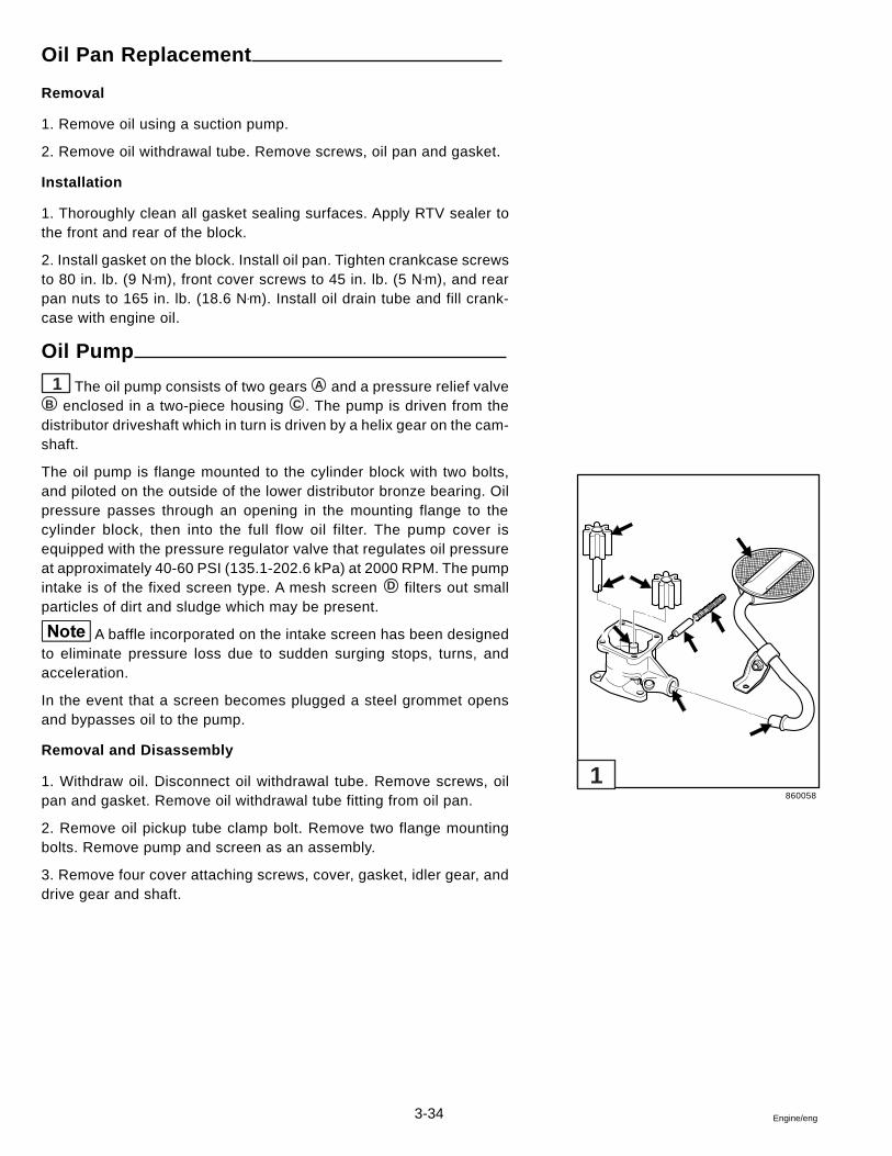
3-34 Engine/eng
Oil Pan Replacement
Removal
1. Remove oil using a suction pump.
2. Remove oil withdrawal tube. Remove screws, oil pan and gasket.
Installation
1. Thoroughly clean all gasket sealing surfaces. Apply RTV sealer tothe front and rear of the block.
2. Install gasket on the block. Install oil pan. Tighten crankcase screwsto 80 in. lb. (9 N•m), front cover screws to 45 in. lb. (5 N•m), and rearpan nuts to 165 in. lb. (18.6 N•m). Install oil drain tube and fill crank-case with engine oil.
Oil Pump
1 The oil pump consists of two gears A and a pressure relief valveB enclosed in a two-piece housing C . The pump is driven from thedistributor driveshaft which in turn is driven by a helix gear on the cam-shaft.
The oil pump is flange mounted to the cylinder block with two bolts,and piloted on the outside of the lower distributor bronze bearing. Oilpressure passes through an opening in the mounting flange to thecylinder block, then into the full flow oil filter. The pump cover isequipped with the pressure regulator valve that regulates oil pressureat approximately 40-60 PSI (135.1-202.6 kPa) at 2000 RPM. The pumpintake is of the fixed screen type. A mesh screen D filters out smallparticles of dirt and sludge which may be present.
A baffle incorporated on the intake screen has been designedto eliminate pressure loss due to sudden surging stops, turns, andacceleration.
In the event that a screen becomes plugged a steel grommet opensand bypasses oil to the pump.
Removal and Disassembly
1. Withdraw oil. Disconnect oil withdrawal tube. Remove screws, oilpan and gasket. Remove oil withdrawal tube fitting from oil pan.
2. Remove oil pickup tube clamp bolt. Remove two flange mountingbolts. Remove pump and screen as an assembly.
3. Remove four cover attaching screws, cover, gasket, idler gear, anddrive gear and shaft.
860058
1
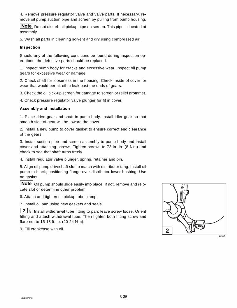
3-35Engine/eng
4. Remove pressure regulator valve and valve parts. If necessary, re-move oil pump suction pipe and screen by pulling from pump housing.
Do not disturb oil pickup pipe on screen. This pipe is located atassembly.
5. Wash all parts in cleaning solvent and dry using compressed air.
Inspection
Should any of the following conditions be found during inspection op-erations, the defective parts should be replaced.
1. Inspect pump body for cracks and excessive wear. Inspect oil pumpgears for excessive wear or damage.
2. Check shaft for looseness in the housing. Check inside of cover forwear that would permit oil to leak past the ends of gears.
3. Check the oil pick-up screen for damage to screen or relief grommet.
4. Check pressure regulator valve plunger for fit in cover.
Assembly and Installation
1. Place drive gear and shaft in pump body. Install idler gear so thatsmooth side of gear will be toward the cover.
2. Install a new pump to cover gasket to ensure correct end clearanceof the gears.
3. Install suction pipe and screen assembly to pump body and installcover and attaching screws. Tighten screws to 72 in. lb. (8 N•m) andcheck to see that shaft turns freely.
4. Install regulator valve plunger, spring, retainer and pin.
5. Align oil pump driveshaft slot to match with distributor tang. Install oilpump to block, positioning flange over distributor lower bushing. Useno gasket.
Oil pump should slide easily into place. If not, remove and relo-cate slot or determine other problem.
6. Attach and tighten oil pickup tube clamp.
7. Install oil pan using new gaskets and seals.
2 8. Install withdrawal tube fitting to pan; leave screw loose. Orientfitting and attach withdrawal tube. Then tighten both fitting screw andflare nut to 15-18 ft. lb. (20-24 N•m).
9. Fill crankcase with oil.
31576
2
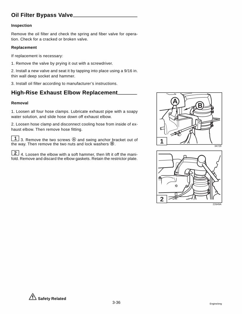
3-36 Engine/eng
34729
22649A
2
1
Oil Filter Bypass Valve
Inspection
Remove the oil filter and check the spring and fiber valve for opera-tion. Check for a cracked or broken valve.
Replacement
If replacement is necessary:
1. Remove the valve by prying it out with a screwdriver.
2. Install a new valve and seat it by tapping into place using a 9/16 in.thin wall deep socket and hammer.
3. Install oil filter according to manufacturer’s instructions.
High-Rise Exhaust Elbow Replacement
Removal
1. Loosen all four hose clamps. Lubricate exhaust pipe with a soapywater solution, and slide hose down off exhaust elbow.
2. Loosen hose clamp and disconnect cooling hose from inside of ex-haust elbow. Then remove hose fitting.
1 3. Remove the two screws A and swing anchor bracket out ofthe way. Then remove the two nuts and lock washers B .
2 4. Loosen the elbow with a soft hammer, then lift it off the mani-fold. Remove and discard the elbow gaskets. Retain the restrictor plate.
Safety Related
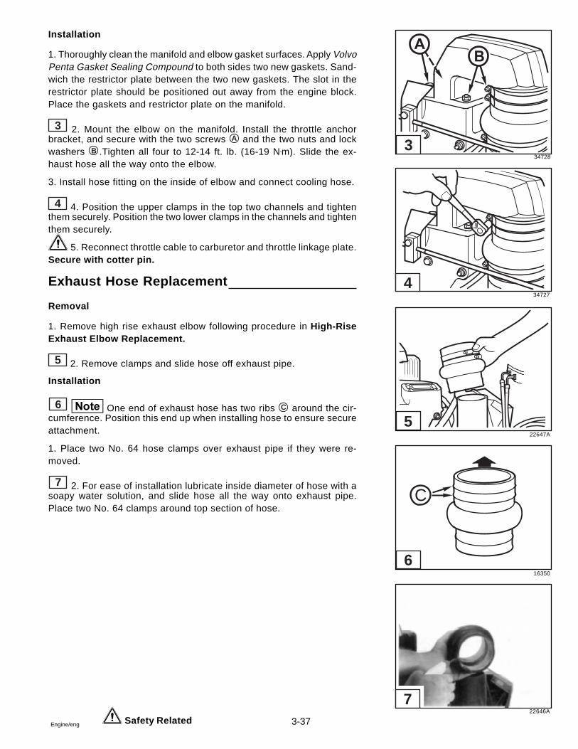
3-37Engine/eng
Installation
1. Thoroughly clean the manifold and elbow gasket surfaces. Apply VolvoPenta Gasket Sealing Compound to both sides two new gaskets. Sand-wich the restrictor plate between the two new gaskets. The slot in therestrictor plate should be positioned out away from the engine block.Place the gaskets and restrictor plate on the manifold.
3 2. Mount the elbow on the manifold. Install the throttle anchorbracket, and secure with the two screws A and the two nuts and lockwashers B .Tighten all four to 12-14 ft. lb. (16-19 N•m). Slide the ex-haust hose all the way onto the elbow.
3. Install hose fitting on the inside of elbow and connect cooling hose.
4 4. Position the upper clamps in the top two channels and tightenthem securely. Position the two lower clamps in the channels and tightenthem securely.
5. Reconnect throttle cable to carburetor and throttle linkage plate.Secure with cotter pin.
Exhaust Hose Replacement
Removal
1. Remove high rise exhaust elbow following procedure in High-RiseExhaust Elbow Replacement.
5 2. Remove clamps and slide hose off exhaust pipe.
Installation
6 One end of exhaust hose has two ribs C around the cir-cumference. Position this end up when installing hose to ensure secureattachment.
1. Place two No. 64 hose clamps over exhaust pipe if they were re-moved.
7 2. For ease of installation lubricate inside diameter of hose with asoapy water solution, and slide hose all the way onto exhaust pipe.Place two No. 64 clamps around top section of hose.
Safety Related
34728
34727
22647A
16350
22646A
C
7
3
4
5
6
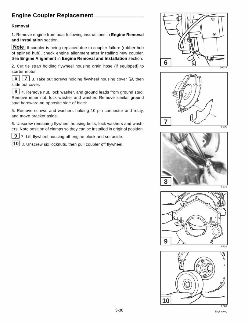
3-38 Engine/eng
Engine Coupler Replacement
Removal
1. Remove engine from boat following instructions in Engine Removaland Installation section.
If coupler is being replaced due to coupler failure (rubber hubof splined hub), check engine alignment after installing new coupler.See Engine Alignment in Engine Removal and Installation section.
2. Cut tie strap holding flywheel housing drain hose (if equipped) tostarter motor.
6 7 3. Take out screws holding flywheel housing cover C , thenslide out cover.
8 4. Remove nut, lock washer, and ground leads from ground stud.Remove inner nut, lock washer and washer. Remove similar groundstud hardware on opposite side of block.
5. Remove screws and washers holding 10 pin connector and relay,and move bracket aside.
6. Unscrew remaining flywheel housing bolts, lock washers and wash-ers. Note position of clamps so they can be installed in original position.
9 7. Lift flywheel housing off engine block and set aside.
10 8. Unscrew six locknuts, then pull coupler off flywheel.
20034
6676
6675
6710
6712
10
9
8
7
6
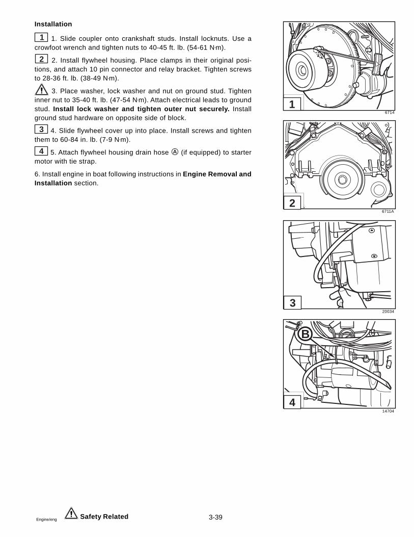
3-39Engine/eng
Installation
1 1. Slide coupler onto crankshaft studs. Install locknuts. Use acrowfoot wrench and tighten nuts to 40-45 ft. lb. (54-61 N•m).
2 2. Install flywheel housing. Place clamps in their original posi-tions, and attach 10 pin connector and relay bracket. Tighten screwsto 28-36 ft. lb. (38-49 N•m).
3. Place washer, lock washer and nut on ground stud. Tighteninner nut to 35-40 ft. lb. (47-54 N•m). Attach electrical leads to groundstud. Install lock washer and tighten outer nut securely. Installground stud hardware on opposite side of block.
3 4. Slide flywheel cover up into place. Install screws and tightenthem to 60-84 in. lb. (7-9 N•m).
4 5. Attach flywheel housing drain hose A (if equipped) to startermotor with tie strap.
6. Install engine in boat following instructions in Engine Removal andInstallation section.
Safety Related
6714
6711A
20034
14704
B
4
3
2
1
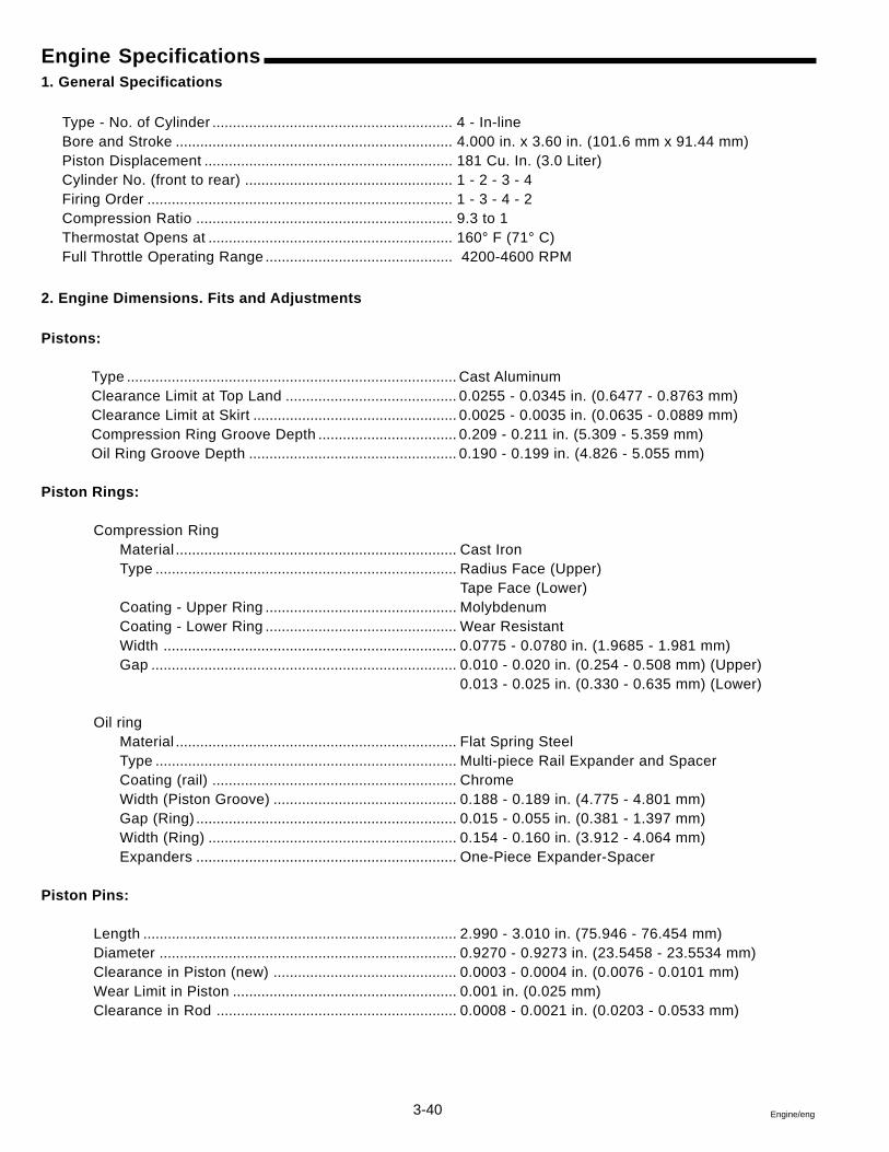
3-40 Engine/eng
Engine Specifications1. General Specifications
Type - No. of Cylinder ........................................................... 4 - In-lineBore and Stroke .................................................................... 4.000 in. x 3.60 in. (101.6 mm x 91.44 mm)Piston Displacement ............................................................. 181 Cu. In. (3.0 Liter)Cylinder No. (front to rear) ................................................... 1 - 2 - 3 - 4Firing Order ........................................................................... 1 - 3 - 4 - 2Compression Ratio ............................................................... 9.3 to 1Thermostat Opens at ............................................................ 160° F (71° C)Full Throttle Operating Range .............................................. 4200-4600 RPM
2. Engine Dimensions. Fits and Adjustments
Pistons:
Type ................................................................................. Cast AluminumClearance Limit at Top Land .......................................... 0.0255 - 0.0345 in. (0.6477 - 0.8763 mm)Clearance Limit at Skirt .................................................. 0.0025 - 0.0035 in. (0.0635 - 0.0889 mm)Compression Ring Groove Depth .................................. 0.209 - 0.211 in. (5.309 - 5.359 mm)Oil Ring Groove Depth ................................................... 0.190 - 0.199 in. (4.826 - 5.055 mm)
Piston Rings:
Compression RingMaterial ..................................................................... Cast IronType .......................................................................... Radius Face (Upper)
Tape Face (Lower)Coating - Upper Ring ............................................... MolybdenumCoating - Lower Ring ............................................... Wear ResistantWidth ........................................................................ 0.0775 - 0.0780 in. (1.9685 - 1.981 mm)Gap ........................................................................... 0.010 - 0.020 in. (0.254 - 0.508 mm) (Upper)
0.013 - 0.025 in. (0.330 - 0.635 mm) (Lower)
Oil ringMaterial ..................................................................... Flat Spring SteelType .......................................................................... Multi-piece Rail Expander and SpacerCoating (rail) ............................................................ ChromeWidth (Piston Groove) ............................................. 0.188 - 0.189 in. (4.775 - 4.801 mm)Gap (Ring) ................................................................ 0.015 - 0.055 in. (0.381 - 1.397 mm)Width (Ring) ............................................................. 0.154 - 0.160 in. (3.912 - 4.064 mm)Expanders ................................................................ One-Piece Expander-Spacer
Piston Pins:
Length ............................................................................. 2.990 - 3.010 in. (75.946 - 76.454 mm)Diameter ......................................................................... 0.9270 - 0.9273 in. (23.5458 - 23.5534 mm)Clearance in Piston (new) ............................................. 0.0003 - 0.0004 in. (0.0076 - 0.0101 mm)Wear Limit in Piston ....................................................... 0.001 in. (0.025 mm)Clearance in Rod ........................................................... 0.0008 - 0.0021 in. (0.0203 - 0.0533 mm)
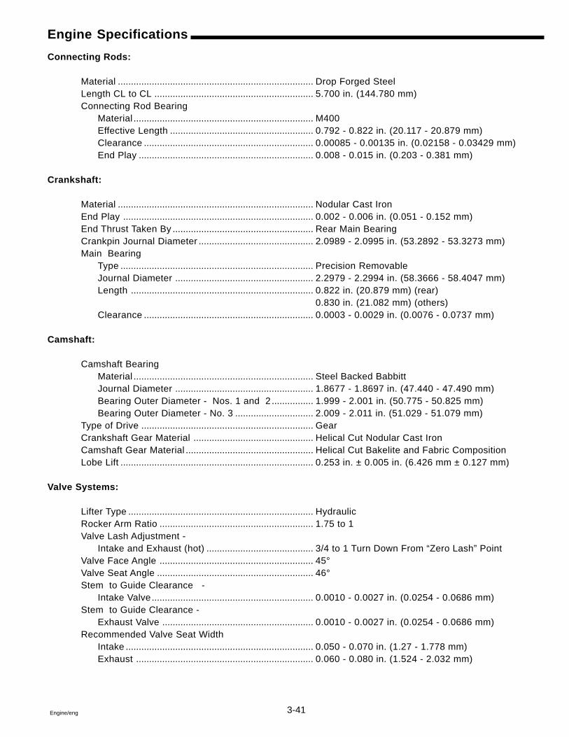
3-41Engine/eng
Engine Specifications
Connecting Rods:
Material ........................................................................... Drop Forged SteelLength CL to CL ............................................................. 5.700 in. (144.780 mm)Connecting Rod Bearing
Material ..................................................................... M400Effective Length ....................................................... 0.792 - 0.822 in. (20.117 - 20.879 mm)Clearance ................................................................. 0.00085 - 0.00135 in. (0.02158 - 0.03429 mm)End Play ................................................................... 0.008 - 0.015 in. (0.203 - 0.381 mm)
Crankshaft:
Material ........................................................................... Nodular Cast IronEnd Play ......................................................................... 0.002 - 0.006 in. (0.051 - 0.152 mm)End Thrust Taken By ...................................................... Rear Main BearingCrankpin Journal Diameter ............................................ 2.0989 - 2.0995 in. (53.2892 - 53.3273 mm)Main Bearing
Type .......................................................................... Precision RemovableJournal Diameter ..................................................... 2.2979 - 2.2994 in. (58.3666 - 58.4047 mm)Length ...................................................................... 0.822 in. (20.879 mm) (rear)
0.830 in. (21.082 mm) (others)Clearance ................................................................. 0.0003 - 0.0029 in. (0.0076 - 0.0737 mm)
Camshaft:
Camshaft BearingMaterial ..................................................................... Steel Backed BabbittJournal Diameter ..................................................... 1.8677 - 1.8697 in. (47.440 - 47.490 mm)Bearing Outer Diameter - Nos. 1 and 2 ................ 1.999 - 2.001 in. (50.775 - 50.825 mm)Bearing Outer Diameter - No. 3 .............................. 2.009 - 2.011 in. (51.029 - 51.079 mm)
Type of Drive .................................................................. GearCrankshaft Gear Material .............................................. Helical Cut Nodular Cast IronCamshaft Gear Material ................................................. Helical Cut Bakelite and Fabric CompositionLobe Lift .......................................................................... 0.253 in. ± 0.005 in. (6.426 mm ± 0.127 mm)
Valve Systems:
Lifter Type ....................................................................... HydraulicRocker Arm Ratio ........................................................... 1.75 to 1Valve Lash Adjustment -
Intake and Exhaust (hot) ......................................... 3/4 to 1 Turn Down From “Zero Lash” PointValve Face Angle ........................................................... 45°Valve Seat Angle ............................................................ 46°Stem to Guide Clearance -
Intake Valve.............................................................. 0.0010 - 0.0027 in. (0.0254 - 0.0686 mm)Stem to Guide Clearance -
Exhaust Valve .......................................................... 0.0010 - 0.0027 in. (0.0254 - 0.0686 mm)Recommended Valve Seat Width
Intake ........................................................................ 0.050 - 0.070 in. (1.27 - 1.778 mm)Exhaust .................................................................... 0.060 - 0.080 in. (1.524 - 2.032 mm)
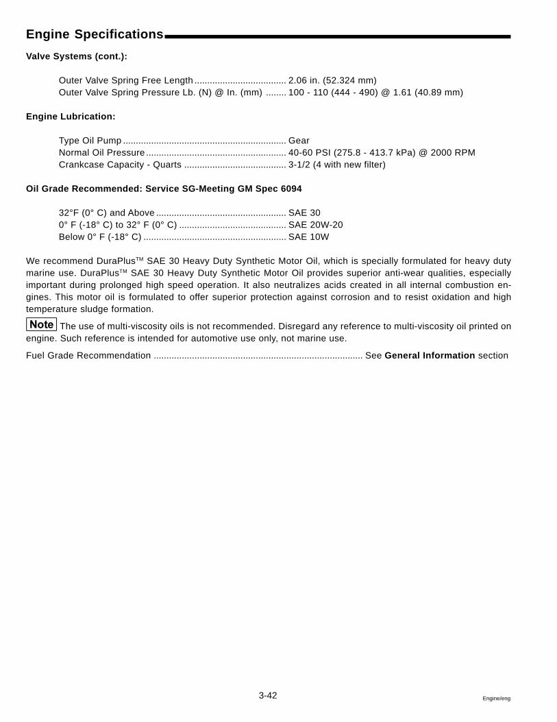
3-42 Engine/eng
Engine Specifications
Valve Systems (cont.):
Outer Valve Spring Free Length .................................... 2.06 in. (52.324 mm)Outer Valve Spring Pressure Lb. (N) @ In. (mm) ........ 100 - 110 (444 - 490) @ 1.61 (40.89 mm)
Engine Lubrication:
Type Oil Pump ................................................................ GearNormal Oil Pressure ....................................................... 40-60 PSI (275.8 - 413.7 kPa) @ 2000 RPMCrankcase Capacity - Quarts ........................................ 3-1/2 (4 with new filter)
Oil Grade Recommended: Service SG-Meeting GM Spec 6094
32°F (0° C) and Above ................................................... SAE 300° F (-18° C) to 32° F (0° C) .......................................... SAE 20W-20Below 0° F (-18° C) ........................................................ SAE 10W
We recommend DuraPlusTM SAE 30 Heavy Duty Synthetic Motor Oil, which is specially formulated for heavy dutymarine use. DuraPlusTM SAE 30 Heavy Duty Synthetic Motor Oil provides superior anti-wear qualities, especiallyimportant during prolonged high speed operation. It also neutralizes acids created in all internal combustion en-gines. This motor oil is formulated to offer superior protection against corrosion and to resist oxidation and hightemperature sludge formation.
The use of multi-viscosity oils is not recommended. Disregard any reference to multi-viscosity oil printed onengine. Such reference is intended for automotive use only, not marine use.
Fuel Grade Recommendation .................................................................................. See General Information section
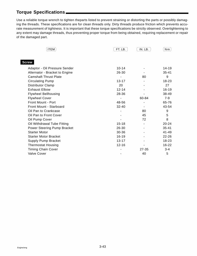
3-43Engine/eng
Torque Specifications
Use a reliable torque wrench to tighten theparts listed to prevent straining or distorting the parts or possibly damag-ing the threads. These specifications are for clean threads only. Dirty threads produce friction which prevents accu-rate measurement of tightness. It is important that these torque specifications be strictly observed. Overtightening toany extent may damage threads, thus preventing proper torque from being obtained, requiring replacement or repairof the damaged part.
ITEM FT. LB. IN. LB. N•m
Screw
Adaptor - Oil Pressure Sender 10-14 - 14-19Alternator - Bracket to Engine 26-30 - 35-41Camshaft Thrust Plate - 80 9Circulating Pump 13-17 - 18-23Distributor Clamp 20 - 27Exhaust Elbow 12-14 - 16-19Flywheel Bellhousing 28-36 - 38-49Flywheel Cover - 60-84 7-9Front Mount - Port 48-56 - 65-76Front Mount - Starboard 32-40 - 43-54Oil Pan to Crankcase - 80 9Oil Pan to Front Cover - 45 5Oil Pump Cover - 72 8Oil Withdrawal Tube Fitting 15-18 - 20-24Power Steering Pump Bracket 26-30 - 35-41Starter Motor 30-36 - 41-49Starter Motor Bracket 16-19 - 22-26Supply Pump Bracket 13-17 - 18-23Thermostat Housing 12-16 - 16-22Timing Chain Cover - 27-35 3-4Valve Cover - 40 5
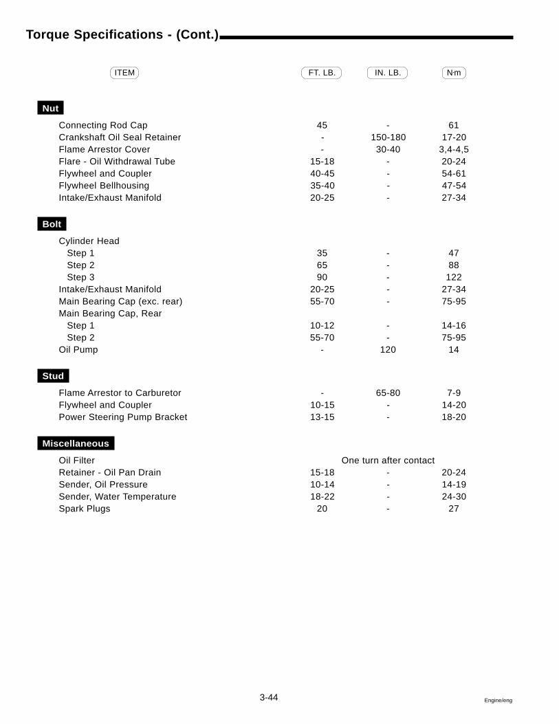
3-44 Engine/eng
Torque Specifications - (Cont.)
ITEM FT. LB. IN. LB. N•m
Nut
Connecting Rod Cap 45 - 61Crankshaft Oil Seal Retainer - 150-180 17-20Flame Arrestor Cover - 30-40 3,4-4,5Flare - Oil Withdrawal Tube 15-18 - 20-24Flywheel and Coupler 40-45 - 54-61Flywheel Bellhousing 35-40 - 47-54Intake/Exhaust Manifold 20-25 - 27-34
Bolt
Cylinder Head Step 1 35 - 47 Step 2 65 - 88 Step 3 90 - 122Intake/Exhaust Manifold 20-25 - 27-34Main Bearing Cap (exc. rear) 55-70 - 75-95Main Bearing Cap, Rear Step 1 10-12 - 14-16 Step 2 55-70 - 75-95Oil Pump - 120 14
Stud
Flame Arrestor to Carburetor - 65-80 7-9Flywheel and Coupler 10-15 - 14-20Power Steering Pump Bracket 13-15 - 18-20
Miscellaneous
Oil Filter One turn after contactRetainer - Oil Pan Drain 15-18 - 20-24Sender, Oil Pressure 10-14 - 14-19Sender, Water Temperature 18-22 - 24-30Spark Plugs 20 - 27
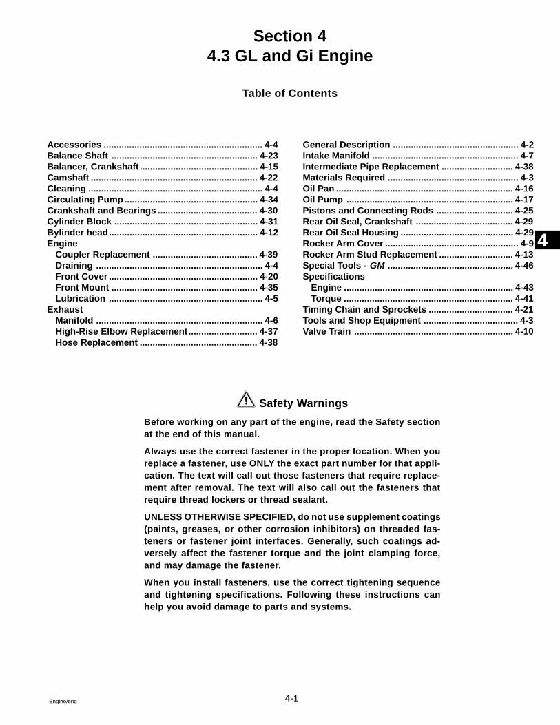
4-1Engine/eng
Section 44.3 GL and Gi Engine
Table of Contents
4
Accessories .............................................................. 4-4Balance Shaft ......................................................... 4-23Balancer, Crankshaft .............................................. 4-15Camshaft ................................................................. 4-22Cleaning .................................................................... 4-4Circulating Pump.................................................... 4-34Crankshaft and Bearings ....................................... 4-30Cylinder Block ........................................................ 4-31Bylinder head.......................................................... 4-12Engine
Coupler Replacement ......................................... 4-39Draining ................................................................. 4-4Front Cover .......................................................... 4-20Front Mount ......................................................... 4-35Lubrication ............................................................ 4-5
ExhaustManifold ................................................................. 4-6High-Rise Elbow Replacement........................... 4-37Hose Replacement .............................................. 4-38
General Description ................................................. 4-2Intake Manifold ......................................................... 4-7Intermediate Pipe Replacement ............................ 4-38Materials Required ................................................... 4-3Oil Pan ..................................................................... 4-16Oil Pump ................................................................. 4-17Pistons and Connecting Rods .............................. 4-25Rear Oil Seal, Crankshaft ...................................... 4-29Rear Oil Seal Housing ............................................ 4-29Rocker Arm Cover .................................................... 4-9Rocker Arm Stud Replacement ............................. 4-13Special Tools - GM ................................................. 4-46Specifications
Engine .................................................................. 4-43Torque .................................................................. 4-41
Timing Chain and Sprockets ................................. 4-21Tools and Shop Equipment ..................................... 4-3Valve Train .............................................................. 4-10
Safety Warnings
Before working on any part of the engine, read the Safety sectionat the end of this manual.
Always use the correct fastener in the proper location. When youreplace a fastener, use ONLY the exact part number for that appli-cation. The text will call out those fasteners that require replace-ment after removal. The text will also call out the fasteners thatrequire thread lockers or thread sealant.
UNLESS OTHERWISE SPECIFIED, do not use supplement coatings(paints, greases, or other corrosion inhibitors) on threaded fas-teners or fastener joint interfaces. Generally, such coatings ad-versely affect the fastener torque and the joint clamping force,and may damage the fastener.
When you install fasteners, use the correct tightening sequenceand tightening specifications. Following these instructions canhelp you avoid damage to parts and systems.
4-2 Engine/eng
General Description
Engine Construction
The 4.3L engine is a liquid-cooled 90 degree V6 type with overheadvalves, a balance shaft, and cast-iron block and cylinder heads.
Cylinder Block
The cylinder block has 6 cylinders arranged in a “V” shape with 3 cyl-inders in each bank. Starting at the front of the engine, cylinders in theright bank are numbered 1-3-5 and cylinders in the left bank are num-bered 2-4-6 (when viewed from the front). The firing order of the cylin-ders is 1-6-5-4-3-2. The cylinders are encircled by coolant jackets.
Cylinder Heads
The cylinder heads have one intake and one exhaust valve for eachcylinder. A spark plug is located between the valves in the side of thecylinder head. The valve guides are integral and the valve rocker armsare retained on individual threaded studs.
Crankshaft
The crankshaft is supported by four crankshaft bearings. The numberfour bearing at the rear of the engine is the end thrust bearing. Thebearings are retained by bearing caps that are machined with the blockfor proper alignment and clearances.
Camshaft
The camshaft is supported by four full round, sleeve-type bearings. Asprocket on the crankshaft drives a camshaft timing chain which inturn drives the camshaft through a sprocket.
Pistons and Connecting Rods
The pistons are made of cast-aluminum alloy using two compressionrings and one oil control ring assembly. Piston pins are offset 0.0354in. (0,9 mm) toward the major thrust side (right side) to reduce pistonslap as the connecting rod travels from one side of the piston to theother side after a stroke. The pins are a press fit in the connecting rodand a floating fit in the piston.
Balance Shaft
The cast-iron balance shaft is mounted in the crankcase above andinline with the camshaft. A camshaft gear drives the gear attached tothe balance shaft. The front end of the balance shaft is supported by aball-type bearing. The rear end of the balance shaft uses a sleeve-type bearing.
4-3Engine/eng
Material Required
DuraPlusTM Synthetic Motor OilVolvo Penta Gasket Sealing CompoundVolvo Penta Thread Sealing Agent3M Scotch Grip Rubber Adhesive 1300GM Adhesive, P/N 12346141GM Engine Oil Supplement, P/N 1052367GM Sealant, P/N 12346004GM Threadlock, P/N 12345382Loctite PrimerBlack Neoprene Dip
Valve Train
The valve train is a ball-pivot type. Motion is transmitted from the cam-shaft through the valve lifter and valve push rod to the valve rocker arm.The valve rocker arm pivots on its ball and transmits the camshaft mo-tion to the valve. The valve lifters with roller followers keep all parts ofthe valve train in constant contact. Each lifter acts as an automatic ad-juster and maintains zero lash in the valve train. This eliminates theneed for periodic valve adjustment.
Intake Manifold
The intake manifold assembly is a two-piece design. The upper portionis made from a composite material and lower portion is cast-aluminum.The throttle body attaches to the upper manifold.
Tools and Shop Equipment
A clean, well-lit, work area should be available. Other necessary equip-ment includes: a suitable parts cleaning tank, compressed air supply,trays to keep parts and fasteners organized, and an adequate set ofhand tools. An approved engine repair stand will help aid with the workand help prevent personal injury or component damage.
Special tools are listed and illustrated throughout this section with acomplete listing at the end of the section. These tools (or their equiva-lents) are specially designed to quickly and safely accomplish the op-erations for which they are intended. The use of these special tools willalso minimize possible damage to engine components. Some precisionmeasuring tools are required for inspection of certain critical compo-nents. Torque wrenches are necessary for the correct assembly of vari-ous parts.
4-4 Engine/eng
Accessories
The various procedures in this manual assume that the engine acces-sories have been removed. These accessories include all of the fol-lowing:
� Power Steering Pump� Alternator� Distributor� Water Supply Pump� Accessory Brackets and Electrical Wiring� Starter Motor
Cleaning
Remove the engine accessories before cleaning to provide better ac-cess to the engine’s exterior surfaces. After removing the distributor,accessory brackets, etc., cover the openings with tape to prevent theentry of contaminants.
Methods used to clean the engine will depend on the means which areavailable. Steam cleaning, pressure washing, or solvent cleaning aresome of the acceptable methods. Allow the engine to dry thoroughlybefore beginning any work.
It is important that the engine be as clean as possible to prevent dirt,water, or any other contaminants from entering critical areas duringdisassembly.
Draining The Engine
Follow the procedures in Section 1, General Information of thismanual to drain crankcase engine oil and the cooling system.
4-5Engine/eng
Engine Lubrication
1 Full pressure lubrication, through a full-flow oil fil-ter is supplied by a gear-type oil pump. Oil is drawn upthrough the oil pump screen and passes through thepump to the oil filter. The oil filter is a full-flow paperelement unit with an anti-drain back valve. An oil filterbypass valve is used to ensure adequate oil supply, inthe event the filter becomes plugged or develops ex-cessive pressure drop.
Filtered oil flows into the main gallery and then to thecamshaft, balance shaft, rear bearing, and crankshaftbearings. The valve lifter oil gallery supplies oil to thevalve lifters. Oil flows from the valve lifters through thehollow valve push rods to the valve rocker arms. Oildrains back to the crankcase through oil drain holes inthe cylinder head. The camshaft timing chain is dripfed from the front camshaft bearing. The pistons andpiston pins are lubricated by oil splash.
DRC6583
1
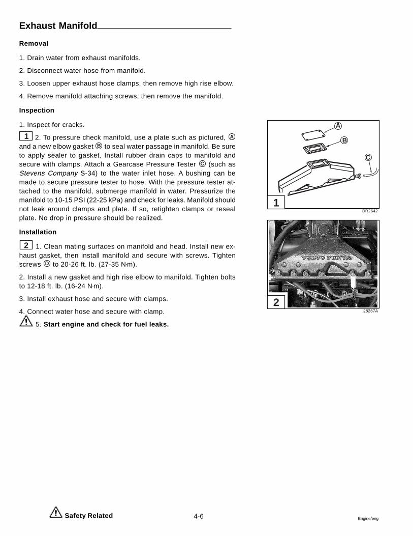
4-6 Engine/eng
Exhaust Manifold
Removal
1. Drain water from exhaust manifolds.
2. Disconnect water hose from manifold.
3. Loosen upper exhaust hose clamps, then remove high rise elbow.
4. Remove manifold attaching screws, then remove the manifold.
Inspection
1. Inspect for cracks.
1 2. To pressure check manifold, use a plate such as pictured, A
and a new elbow gasket B to seal water passage in manifold. Be sureto apply sealer to gasket. Install rubber drain caps to manifold andsecure with clamps. Attach a Gearcase Pressure Tester C (such asStevens Company S-34) to the water inlet hose. A bushing can bemade to secure pressure tester to hose. With the pressure tester at-tached to the manifold, submerge manifold in water. Pressurize themanifold to 10-15 PSI (22-25 kPa) and check for leaks. Manifold shouldnot leak around clamps and plate. If so, retighten clamps or resealplate. No drop in pressure should be realized.
Installation
2 1. Clean mating surfaces on manifold and head. Install new ex-haust gasket, then install manifold and secure with screws. Tightenscrews D to 20-26 ft. lb. (27-35 N•m).
2. Install a new gasket and high rise elbow to manifold. Tighten boltsto 12-18 ft. lb. (16-24 N•m).
3. Install exhaust hose and secure with clamps.
4. Connect water hose and secure with clamp.
5. Start engine and check for fuel leaks.
Safety Related
DR2642
28287A
A
B
C
1
2
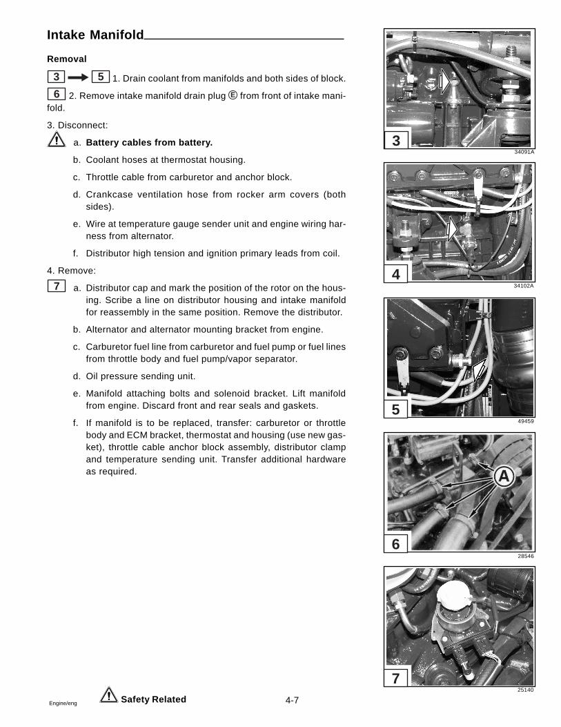
4-7Engine/eng
Intake Manifold
Removal
3 5 1. Drain coolant from manifolds and both sides of block.
6 2. Remove intake manifold drain plug E from front of intake mani-fold.
3. Disconnect:
a. Battery cables from battery.
b. Coolant hoses at thermostat housing.
c. Throttle cable from carburetor and anchor block.
d. Crankcase ventilation hose from rocker arm covers (bothsides).
e. Wire at temperature gauge sender unit and engine wiring har-ness from alternator.
f. Distributor high tension and ignition primary leads from coil.
4. Remove:
7 a. Distributor cap and mark the position of the rotor on the hous-ing. Scribe a line on distributor housing and intake manifoldfor reassembly in the same position. Remove the distributor.
b. Alternator and alternator mounting bracket from engine.
c. Carburetor fuel line from carburetor and fuel pump or fuel linesfrom throttle body and fuel pump/vapor separator.
d. Oil pressure sending unit.
e. Manifold attaching bolts and solenoid bracket. Lift manifoldfrom engine. Discard front and rear seals and gaskets.
f. If manifold is to be replaced, transfer: carburetor or throttlebody and ECM bracket, thermostat and housing (use new gas-ket), throttle cable anchor block assembly, distributor clampand temperature sending unit. Transfer additional hardwareas required.
Safety Related
34091A
34102A
49459
28546
25140
7
6
5
4
3
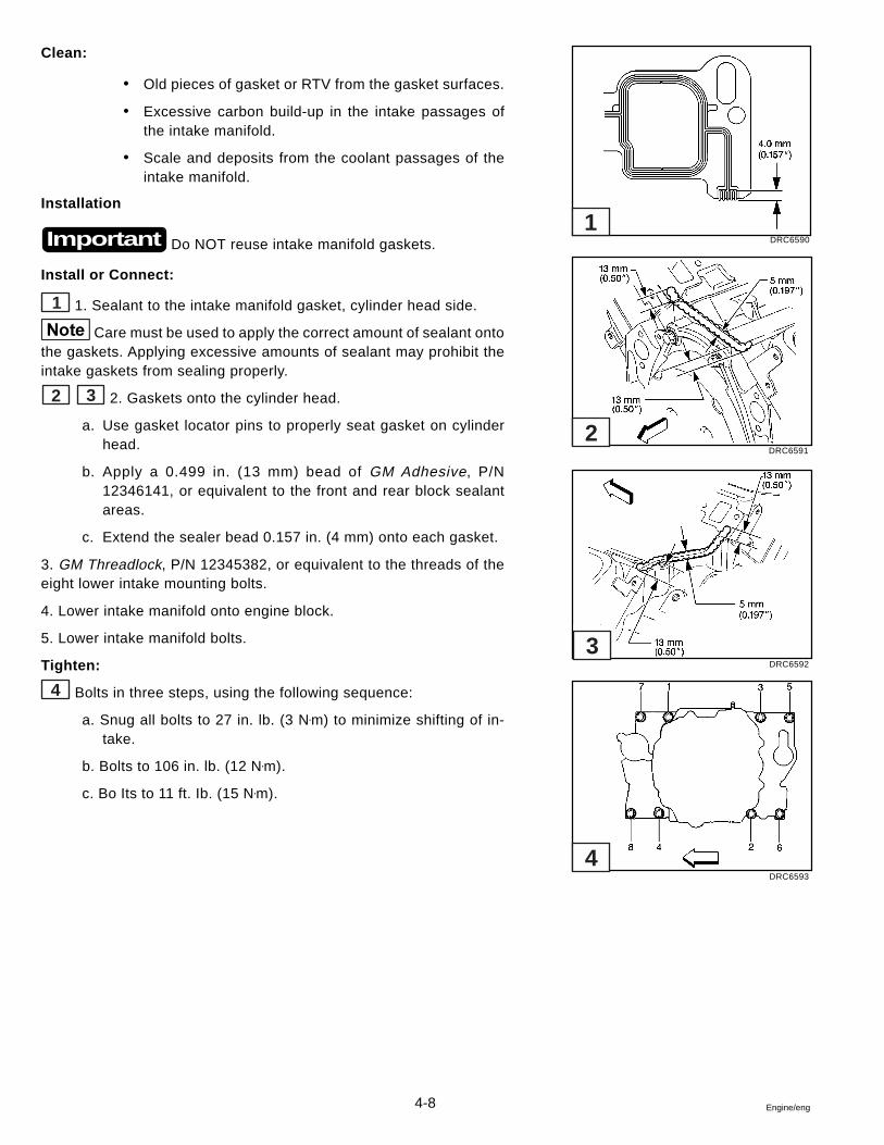
4-8 Engine/eng
Clean:
� Old pieces of gasket or RTV from the gasket surfaces.
� Excessive carbon build-up in the intake passages ofthe intake manifold.
� Scale and deposits from the coolant passages of theintake manifold.
Installation
Do NOT reuse intake manifold gaskets.
Install or Connect:
1 1. Sealant to the intake manifold gasket, cylinder head side.
Care must be used to apply the correct amount of sealant ontothe gaskets. Applying excessive amounts of sealant may prohibit theintake gaskets from sealing properly.
2 3 2. Gaskets onto the cylinder head.
a. Use gasket locator pins to properly seat gasket on cylinderhead.
b. Apply a 0.499 in. (13 mm) bead of GM Adhesive, P/N12346141, or equivalent to the front and rear block sealantareas.
c. Extend the sealer bead 0.157 in. (4 mm) onto each gasket.
3. GM Threadlock, P/N 12345382, or equivalent to the threads of theeight lower intake mounting bolts.
4. Lower intake manifold onto engine block.
5. Lower intake manifold bolts.
Tighten:
4 Bolts in three steps, using the following sequence:
a. Snug all bolts to 27 in. lb. (3 N•m) to minimize shifting of in-take.
b. Bolts to 106 in. lb. (12 N•m).
c. Bo Its to 11 ft. Ib. (15 N•m).
Important DRC6590
DRC6591
DRC6592
DRC6593
1
2
3
4
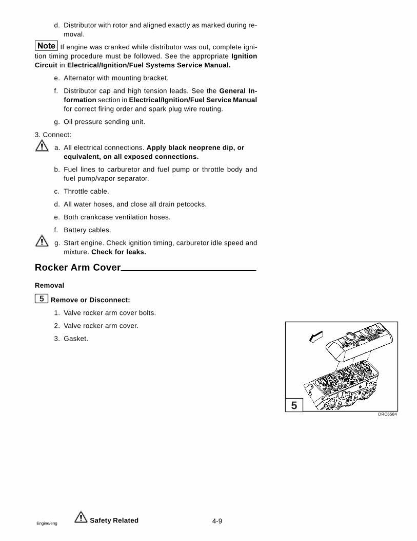
4-9Engine/eng
d. Distributor with rotor and aligned exactly as marked during re-moval.
If engine was cranked while distributor was out, complete igni-tion timing procedure must be followed. See the appropriate IgnitionCircuit in Electrical/Ignition/Fuel Systems Service Manual.
e. Alternator with mounting bracket.
f. Distributor cap and high tension leads. See the General In-formation section in Electrical/Ignition/Fuel Service Manualfor correct firing order and spark plug wire routing.
g. Oil pressure sending unit.
3. Connect:
a. All electrical connections. Apply black neoprene dip, orequivalent, on all exposed connections.
b. Fuel lines to carburetor and fuel pump or throttle body andfuel pump/vapor separator.
c. Throttle cable.
d. All water hoses, and close all drain petcocks.
e. Both crankcase ventilation hoses.
f. Battery cables.
g. Start engine. Check ignition timing, carburetor idle speed andmixture. Check for leaks.
Rocker Arm Cover
Removal
5 Remove or Disconnect:
1. Valve rocker arm cover bolts.
2. Valve rocker arm cover.
3. Gasket.
Safety Related
DRC6584
5
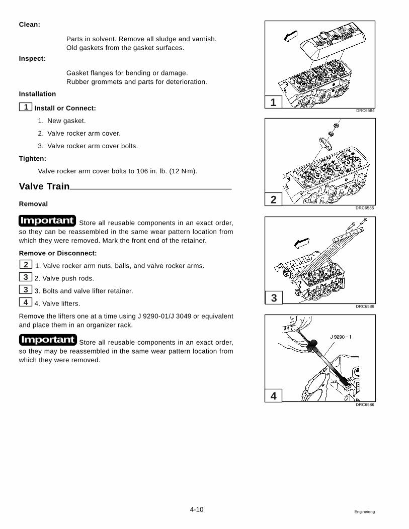
4-10 Engine/eng
Clean:
Parts in solvent. Remove all sludge and varnish.Old gaskets from the gasket surfaces.
Inspect:
Gasket flanges for bending or damage.Rubber grommets and parts for deterioration.
Installation
1 Install or Connect:
1. New gasket.
2. Valve rocker arm cover.
3. Valve rocker arm cover bolts.
Tighten:
Valve rocker arm cover bolts to 106 in. lb. (12 N•m).
Valve Train
Removal
Store all reusable components in an exact order,so they can be reassembled in the same wear pattern location fromwhich they were removed. Mark the front end of the retainer.
Remove or Disconnect:
2 1. Valve rocker arm nuts, balls, and valve rocker arms.
3 2. Valve push rods.
3 3. Bolts and valve lifter retainer.
4 4. Valve lifters.
Remove the lifters one at a time using J 9290-01/J 3049 or equivalentand place them in an organizer rack.
Store all reusable components in an exact order,so they may be reassembled in the same wear pattern location fromwhich they were removed.
Important
Important
DRC6584
DRC6585
DRC6588
DRC6586
1
2
3
4
4-11Engine/eng
Clean:
� All parts in clean solvent and dry them with compressedair.
� Make sure oil passages in valve push rods are clear.
Inspect:
� Valve rocker arms and balls at their mating surfaces.These surfaces should be free from wear or any dam-age.
� Valve rocker arm areas that contact the valve stems andthe socket areas that contact the ends of the valve pushrods. These areas should be free of damage or wear.
� Valve rocker arm nuts.
� Valve push rod ends for scoring, roughness, or bends.
Roll the valve push rod on a flat surface to determine itsstraightness. If the rod is bent, the rod will not roll freely. Replace ifnecessary.
Valve Lifters
This engine uses hydraulic valve lifters. Valve lifters are serviced onlyas an assembly. No internal parts are available. Service is limited to adisassembly and cleaning. Discard valve lifters that are excessively wornor damaged.
Whenever the camshaft needs to be replaced, a newset of valve lifters must also be installed.
Installation
Replace all valve roller lifters, change the engine oiland filter, and add GM Engine Oil Supplement, P/N 1052367, or equiva-lent to the engine oil whenever a new camshaft is installed.
Lubricate the valve lifter bodies and roller with GM Engine OilSupplement, P/N 1052367, or equivalent.
Install or Connect:
3 1. Valve lifters to the block.
3 2. Valve lifter guide.
� Note previously made mark on valve lifter guide. Refer-ence mark should be pointing toward front of engine.
Important
Important
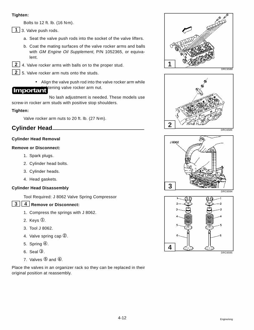
4-12 Engine/eng
Tighten:
Bolts to 12 ft. lb. (16 N•m).
1 3. Valve push rods.
a. Seat the valve push rods into the socket of the valve lifters.
b. Coat the mating surfaces of the valve rocker arms and ballswith GM Engine Oil Supplement, P/N 1052365, or equiva-lent.
2 4. Valve rocker arms with balls on to the proper stud.
2 5. Valve rocker arm nuts onto the studs.
� Align the valve push rod into the valve rocker arm whiletightening valve rocker arm nut.
No lash adjustment is needed. These models usescrew-in rocker arm studs with positive stop shoulders.
Tighten:
Valve rocker arm nuts to 20 ft. lb. (27 N•m).
Cylinder Head
Cylinder Head Removal
Remove or Disconnect:
1. Spark plugs.
2. Cylinder head bolts.
3. Cylinder heads.
4. Head gaskets.
Cylinder Head Disassembly
Tool Required: J 8062 Valve Spring Compressor
3 4 Remove or Disconnect:
1. Compress the springs with J 8062.
2. Keys 1 .
3. Tool J 8062.
4. Valve spring cap 2 .
5. Spring 4 .
6. Seal 3 .
7. Valves 5 and 6 .
Place the valves in an organizer rack so they can be replaced in theiroriginal position at reassembly.
Important
DRC6588
DRC6589
DRC6594
DRC6595
1
2
3
4
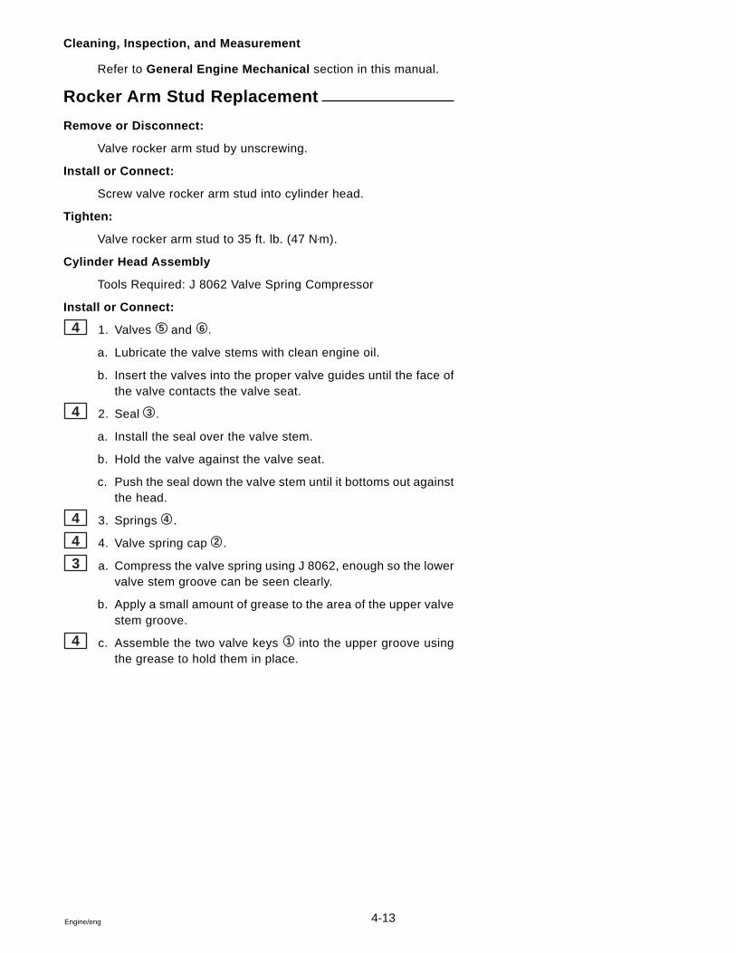
4-13Engine/eng
Cleaning, Inspection, and Measurement
Refer to General Engine Mechanical section in this manual.
Rocker Arm Stud Replacement
Remove or Disconnect:
Valve rocker arm stud by unscrewing.
Install or Connect:
Screw valve rocker arm stud into cylinder head.
Tighten:
Valve rocker arm stud to 35 ft. lb. (47 N•m).
Cylinder Head Assembly
Tools Required: J 8062 Valve Spring Compressor
Install or Connect:
4 1. Valves 5 and 6 .
a. Lubricate the valve stems with clean engine oil.
b. Insert the valves into the proper valve guides until the face ofthe valve contacts the valve seat.
4 2. Seal 3 .
a. Install the seal over the valve stem.
b. Hold the valve against the valve seat.
c. Push the seal down the valve stem until it bottoms out againstthe head.
4 3. Springs 4 .
4 4. Valve spring cap 2 .
3 a. Compress the valve spring using J 8062, enough so the lowervalve stem groove can be seen clearly.
b. Apply a small amount of grease to the area of the upper valvestem groove.
4 c. Assemble the two valve keys 1 into the upper groove usingthe grease to hold them in place.
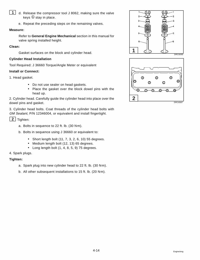
4-14 Engine/eng
1 d. Release the compressor tool J 8062, making sure the valvekeys 1 stay in place.
e. Repeat the preceding steps on the remaining valves.
Measure:
Refer to General Engine Mechanical section in this manual forvalve spring installed height.
Clean:
Gasket surfaces on the block and cylinder head.
Cylinder Head Installation
Tool Required: J 36660 Torque/Angle Meter or equivalent
Install or Connect:
1. Head gasket.
� Do not use sealer on head gaskets.� Place the gasket over the block dowel pins with the
head up.
2. Cylinder head. Carefully guide the cylinder head into place over thedowel pins and gasket.
3. Cylinder head bolts. Coat threads of the cylinder head bolts withGM Sealant, P/N 12346004, or equivalent and install fingertight.
2 Tighten:
a. Bolts in sequence to 22 ft. lb. (30 N•m).
b. Bolts in sequence using J 36660 or equivalent to:
� Short length bolt (11, 7, 3, 2, 6, 10) 55 degrees.� Medium length bolt (12, 13) 65 degrees.� Long length bolt (1, 4, 8, 5, 9) 75 degrees.
4. Spark plugs.
Tighten:
a. Spark plug into new cylinder head to 22 ft. lb. (30 N•m).
b. All other subsequent installations to 15 ft. lb. (20 N•m).
DRC6595
DRC6587
1
2
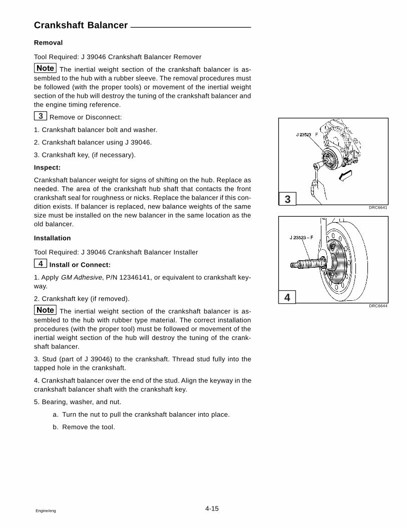
4-15Engine/eng
Crankshaft Balancer
Removal
Tool Required: J 39046 Crankshaft Balancer Remover
The inertial weight section of the crankshaft balancer is as-sembled to the hub with a rubber sleeve. The removal procedures mustbe followed (with the proper tools) or movement of the inertial weightsection of the hub will destroy the tuning of the crankshaft balancer andthe engine timing reference.
3 Remove or Disconnect:
1. Crankshaft balancer bolt and washer.
2. Crankshaft balancer using J 39046.
3. Crankshaft key, (if necessary).
Inspect:
Crankshaft balancer weight for signs of shifting on the hub. Replace asneeded. The area of the crankshaft hub shaft that contacts the frontcrankshaft seal for roughness or nicks. Replace the balancer if this con-dition exists. If balancer is replaced, new balance weights of the samesize must be installed on the new balancer in the same location as theold balancer.
Installation
Tool Required: J 39046 Crankshaft Balancer Installer
4 Install or Connect:
1. Apply GM Adhesive, P/N 12346141, or equivalent to crankshaft key-way.
2. Crankshaft key (if removed).
The inertial weight section of the crankshaft balancer is as-sembled to the hub with rubber type material. The correct installationprocedures (with the proper tool) must be followed or movement of theinertial weight section of the hub will destroy the tuning of the crank-shaft balancer.
3. Stud (part of J 39046) to the crankshaft. Thread stud fully into thetapped hole in the crankshaft.
4. Crankshaft balancer over the end of the stud. Align the keyway in thecrankshaft balancer shaft with the crankshaft key.
5. Bearing, washer, and nut.
a. Turn the nut to pull the crankshaft balancer into place.
b. Remove the tool.
DRC6641
DRC6644
3
4

4-16 Engine/eng
6. Crankshaft balancer bolt and washer.
Tighten:
Bolt to 74 ft. lb. (100 N•m).
Oil Pan
Removal
1 Remove or Disconnect:
1. Oil pan nuts.
2. Oil pan bolts.
3. Oil pan.
4. Gasket.
Clean:
� Parts in solvent. Remove all sludge and varnish.
� Old gaskets and sealant from the gasket surfaces.
Inspect:
� Gasket flanges for bending or damage.
� Oil pan for damage or cracks.
� Oil pan deflector for lack of fit.
� Drain plug threads for stripping.
Installation
Tool Required: J 34673 Straight Edge or Equivalent
The alignment between the rear of the oil pan andrear of the block flange is critical. The two surfaces must be flush toprovide a rigid engine-to-transom bracket alignment.
Install or Connect:
2 3 Apply GM Adhesive, P/N 12346141, or equivalent to theengine front cover to block joint and to the rear crankshaft housing toblock joint. Apply the sealant about 1.00 in. (25,4 mm) in both direc-tions from each of the four corners.
1. Oil pan gasket onto pan.
Important
DRC6642
DRC6639
DRC6640
1
2
3
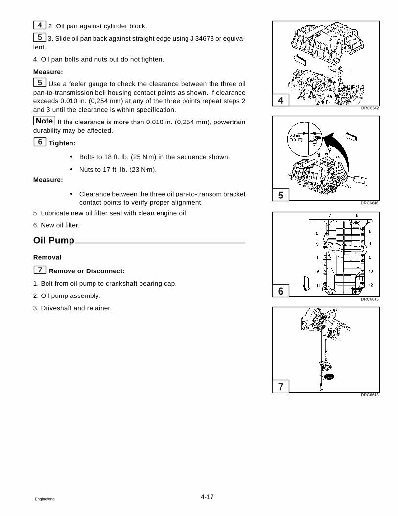
4-17Engine/eng
4 2. Oil pan against cylinder block.
5 3. Slide oil pan back against straight edge using J 34673 or equiva-lent.
4. Oil pan bolts and nuts but do not tighten.
Measure:
5 Use a feeler gauge to check the clearance between the three oilpan-to-transmission bell housing contact points as shown. If clearanceexceeds 0.010 in. (0,254 mm) at any of the three points repeat steps 2and 3 until the clearance is within specification.
If the clearance is more than 0.010 in. (0,254 mm), powertraindurability may be affected.
6 Tighten:
� Bolts to 18 ft. lb. (25 N•m) in the sequence shown.
� Nuts to 17 ft. lb. (23 N•m).
Measure:
� Clearance between the three oil pan-to-transom bracketcontact points to verify proper alignment.
5. Lubricate new oil filter seal with clean engine oil.
6. New oil filter.
Oil Pump
Removal
7 Remove or Disconnect:
1. Bolt from oil pump to crankshaft bearing cap.
2. Oil pump assembly.
3. Driveshaft and retainer.
DRC6642
DRC6646
DRC6645
DRC6643
7
6
5
4
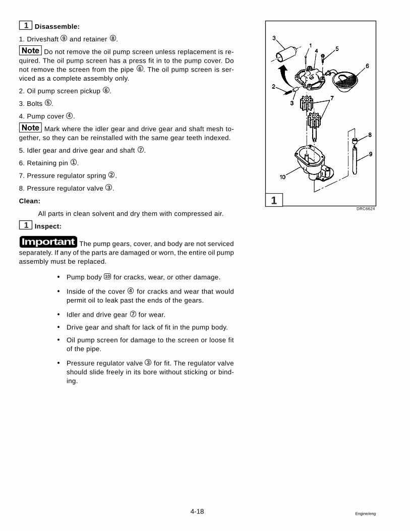
4-18 Engine/eng
1 Disassemble:
1. Driveshaft 9 and retainer 8 .
Do not remove the oil pump screen unless replacement is re-quired. The oil pump screen has a press fit in to the pump cover. Donot remove the screen from the pipe 6 . The oil pump screen is ser-viced as a complete assembly only.
2. Oil pump screen pickup 6 .
3. Bolts 5 .
4. Pump cover 4 .
Mark where the idler gear and drive gear and shaft mesh to-gether, so they can be reinstalled with the same gear teeth indexed.
5. Idler gear and drive gear and shaft 7 .
6. Retaining pin 1 .
7. Pressure regulator spring 2 .
8. Pressure regulator valve 3 .
Clean:
All parts in clean solvent and dry them with compressed air.
1 Inspect:
The pump gears, cover, and body are not servicedseparately. If any of the parts are damaged or worn, the entire oil pumpassembly must be replaced.
� Pump body 10 for cracks, wear, or other damage.
� Inside of the cover 4 for cracks and wear that wouldpermit oil to leak past the ends of the gears.
� Idler and drive gear 7 for wear.
� Drive gear and shaft for lack of fit in the pump body.
� Oil pump screen for damage to the screen or loose fitof the pipe.
� Pressure regulator valve 3 for fit. The regulator valveshould slide freely in its bore without sticking or bind-ing.
Important
DRC6624
1
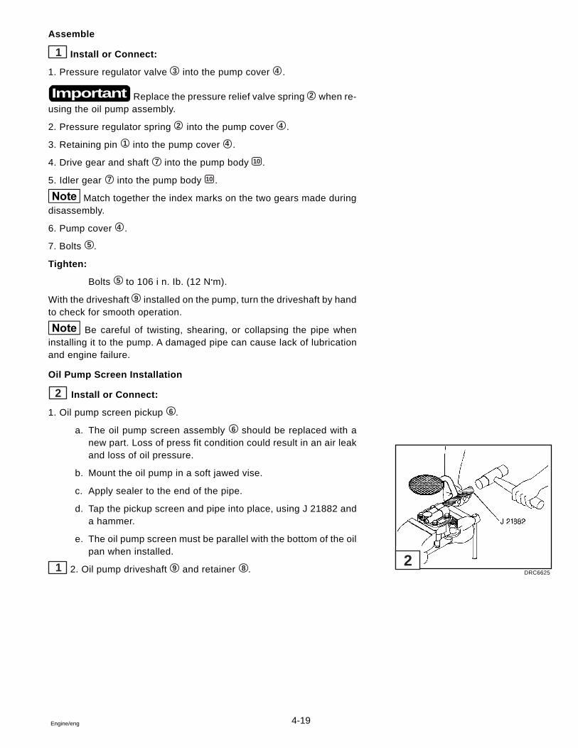
4-19Engine/eng
Assemble
1 Install or Connect:
1. Pressure regulator valve 3 into the pump cover 4 .
Replace the pressure relief valve spring 2 when re-using the oil pump assembly.
2. Pressure regulator spring 2 into the pump cover 4 .
3. Retaining pin 1 into the pump cover 4 .
4. Drive gear and shaft 7 into the pump body 10 .
5. Idler gear 7 into the pump body 10 .
Match together the index marks on the two gears made duringdisassembly.
6. Pump cover 4 .
7. Bolts 5 .
Tighten:
Bolts 5 to 106 i n. Ib. (12 N•m).
With the driveshaft 9 installed on the pump, turn the driveshaft by handto check for smooth operation.
Be careful of twisting, shearing, or collapsing the pipe wheninstalling it to the pump. A damaged pipe can cause lack of lubricationand engine failure.
Oil Pump Screen Installation
2 Install or Connect:
1. Oil pump screen pickup 6 .
a. The oil pump screen assembly 6 should be replaced with anew part. Loss of press fit condition could result in an air leakand loss of oil pressure.
b. Mount the oil pump in a soft jawed vise.
c. Apply sealer to the end of the pipe.
d. Tap the pickup screen and pipe into place, using J 21882 anda hammer.
e. The oil pump screen must be parallel with the bottom of the oilpan when installed.
1 2. Oil pump driveshaft 9 and retainer 8 .
Important
DRC6625
2
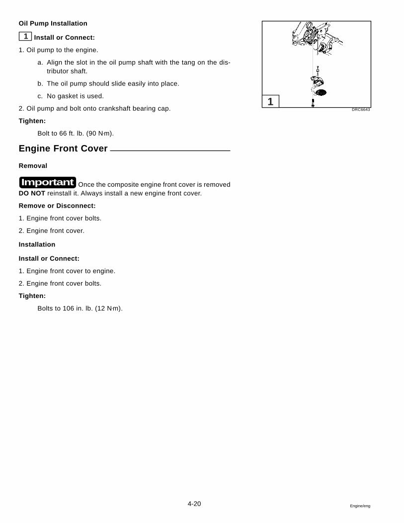
4-20 Engine/eng
Oil Pump Installation
1 Install or Connect:
1. Oil pump to the engine.
a. Align the slot in the oil pump shaft with the tang on the dis-tributor shaft.
b. The oil pump should slide easily into place.
c. No gasket is used.
2. Oil pump and bolt onto crankshaft bearing cap.
Tighten:
Bolt to 66 ft. lb. (90 N•m).
Engine Front Cover
Removal
Once the composite engine front cover is removedDO NOT reinstall it. Always install a new engine front cover.
Remove or Disconnect:
1. Engine front cover bolts.
2. Engine front cover.
Installation
Install or Connect:
1. Engine front cover to engine.
2. Engine front cover bolts.
Tighten:
Bolts to 106 in. lb. (12 N•m).
Important
DRC66431
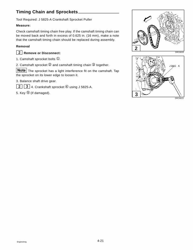
4-21Engine/eng
Timing Chain and Sprockets
Tool Required: J 5825-A Crankshaft Sprocket Puller
Measure:
Check camshaft timing chain free play. If the camshaft timing chain canbe moved back and forth in excess of 0.625 in. (16 mm), make a notethat the camshaft timing chain should be replaced during assembly.
Removal
2 Remove or Disconnect:
1. Camshaft sprocket bolts 1 .
2. Camshaft sprocket 2 and camshaft timing chain 3 together.
The sprocket has a light interference fit on the camshaft. Tapthe sprocket on its lower edge to loosen it.
3. Balance shaft drive gear.
2 3 4. Crankshaft sprocket 4 using J 5825-A.
5. Key 5 (if damaged).
DRC6633
DRC6615
2
3
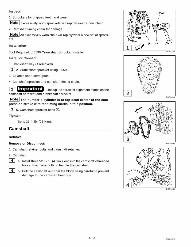
4-22 Engine/eng
Inspect:
1. Sprockets for chipped teeth and wear.
Excessively worn sprockets will rapidly wear a new chain.
2. Camshaft timing chain for damage.
An excessively worn chain will rapidly wear a new set of sprock-ets.
Installation
Tool Required: J 5590 Crankshaft Sprocket Installer
Install or Connect:
1. Crankshaft key (if removed).
1 2. Crankshaft sprocket using J 5590.
3. Balance shaft drive gear.
4. Camshaft sprocket and camshaft timing chain.
2 Line up the sprocket alignment marks on thecamshaft sprocket and crankshaft sprocket.
The number 4 cylinder is at top dead center of the com-pression stroke with the timing marks in this position.
3 5. Camshaft sprocket bolts 1 .
Tighten:
Bolts 21 ft. lb. (28 N•m).
Camshaft
Removal
Remove or Disconnect:
1. Camshaft retainer bolts and camshaft retainer.
2. Camshaft.
4 a. Install three 5/16 - 18 (4.0 in.) long into the camshafts threadedholes. Use these bolts to handle the camshaft.
4 b. Pull the camshaft out from the block being careful to preventdamage to the camshaft bearings.
Important
DRC6694
DRC6634
DRC6633
DRC6635
1
2
3
4
4-23Engine/eng
Measure:
Camshaft Journals. Refer to General Engine Mechanical section inthis manual.
Bearings
Refer to General Engine Mechanical section in this manual for cam-shaft bearing disassembly, cleaning, inspection, and assembly.
Installation
Install or Connect:
Coat the camshaft lobes and journals with a high quality GMEngine Oil Supplement, P/N 1052367, or equivalent. Apply GM EngineOil Supplement, P/N 1052367, or equivalent to all the teeth on the dis-tributor drive gear.
4 1. Two or three 5/16 - 18 (4.0 in.) long bolts into the camshaftthreaded holes. Use these bolts to handle the camshaft.
4 2. Camshaft into the engine. Handle the camshaft carefully to pre-vent damage to the camshaft bearings.
3. Camshaft retainer and retainer bolts.
� Coat camshaft retainer plate with GM Engine Oil Supple-ment, P/N 1052367, or equivalent.
Tighten:
Bolts to 124 in. lb. (14 N•m).
Balance Shaft
Removal
Tools Required: J 38834 Balance Shaft Bearing Service Kit
J 26941 Rear Balance Shaft Bearing Remover
5 Remove or Disconnect:
1. Bolt 1 .
2. Driven gear 2 .
3. Retainer bolts 5 .
4. Retainer 3 .
5 6 5. Balance shaft 4 using a soft faced hammer.
7 6. Balance shaft rear bearing using J 38834 and J 26941.
DRC6631
DRC6617
DRC6618
5
6
7
4-24 Engine/eng
Inspect:
� Balance shaft front roller bearing and rear sleeve bear-ing for damage or excessive wear. The bearings areserviced as an assembly. Use the proper tools for prop-erly servicing the bearings.
� Balance shaft drive and driven gears for nicks or burrs.Replace gears that are damaged.
� Front and rear bearing journal diameters. Replace thebalance shaft if the diameter exceeds the specifications.Refer to Specifications in this section.
� Rear sleeve bearing journal clearance. Replace the bal-ance shaft if the clearance exceeds the specification.Refer to Specifications in this section.
Installation
Tools Required: J 38834 Balance Shaft Bearing Service Kit
J 36996 Balance Shaft Installer
J 8092 Driver Handle
J 36660 Torque/Angle Meter or equivalent
Install or Connect:
1. Dip bearing in clean engine oil before installation.
1 2 2. Balance shaft rear bearing using J 38834.
3 3. Balance shaft into block using J 36996 and J 8092.
a. Dip the front balance shaft bearing into clean engine oil be-fore assembly.
b. Retaining ring on balance shaft front bearing must be seatedon case.
4 4. Install balance shaft bearing retainer 3 and bolts 5 .
Tighten:
4 Balance shaft retainer bolts 5 to 124 in. lb. (14 N•m).
4 5. Balance shaft driven gear 2 and bolt 1 .
Tighten:
4 Balance shaft driven gear bolt 1 to 15 ft. lb. (20 N•m) plus anadditional turn of 35 degrees using J 36660 or equivalent.
4 Rotate balance shaft 4 by hand to make sure there isclearance between the balance shaft and retainer. If balance shaft doesnot rotate freely, check to be sure retaining ring on front bearing isseated in case.
DRC6629
DRC6618
DRC6630
DRC6631
4
3
2
1
4-25Engine/eng
• Turn the camshaft with the balance shaft drive gear tem-porarily installed. The timing mark on the drive gear mustbe straight up.
• With the balance shaft drive gear removed, turn the bal-ance shaft so the timing mark on the driven gear pointsstraight down.
6. Balance shaft drive gear onto camshaft.
Important Make sure the timing marks on the balance shaft drivegear and driven gear line up.
Pistons and Connecting Rods
Removal
Tool Required: J 5239 Guide Set
Remove or Disconnect:
Before attempting to remove piston, refer to General EngineMechanical section in this manual for cylinder bore ridge reamer pro-cedures.
1. Mark the cylinder numbers on the tops of each piston. Mark themfrom the front to the rear, with the engine in an upright position andviewed from the front.
� The right bank is numbered 1-3-5� The left bank is numbered 2-4-6
2. Check the connecting rod and cap for identification marks. If reusingthe connecting rods, mark the parts in the same way as the pistons.
Important Store the connecting rod and cap together as mating
parts, so they may be reassembled in the same wear pattern and bal-ance in which they were removed.
3. Connecting rod nuts, cap and bearings.
Important If reusing bearings, keep bearings with their originalconnecting rod and cap.
5
5
DRC66325
4-26 Engine/eng
4. Connecting rod and piston.
1 a. Attach J 5239 to the connecting rod bolts.
1 b. Use the long guide rod J 5239 to push the connecting rodand piston out of the bore.
Disassembly
Refer to General Engine Mechanical section in this manual for pistonand connecting rod disassembly.
Assembly
Refer to General Engine Mechanical section in this manual for pistonand connecting rod assembly.
Bearing Selection
Important Connecting rod bearings are of the precision inserttype and do not use shims for adjustment. DO NOT FILE RODS ORROD CAPS.
If clearances are excessive, install a new bearing. Service bearingsare available in standard size 0.001 in. (0,0254 mm) and 0.002 in.(0,0508 mm) undersize for use with new and used standard size crank-shafts. For reconditioned crankshafts 0.010 in. (0,254 mm) and 0.020in. (0,508 mm) undersize bearings are available.
Piston Selection
Measuring the Piston
Check the used piston to cylinder bore clearance, as follows:
2 1. Cylinder bore diameter. Use a telescoping bore gauge, located2.5 in. (65 mm) below the top of the cylinder bore.
3 2. Piston diameter. Measure the skirt at a right angle to the pistonpin hole, 1.0 in. (25 mm) below the oil ring groove.
DRC6619
DRC6507
DRC6514
J 8087
1
2
3
4-27Engine/eng
Measure piston diameter at 70 degrees F (20 degrees C).
3. Subtract the piston diameter from the cylinder bore diameter to de-termine piston to bore clearance.
4. Locate the piston-to-bore clearance, refer to Engine Specifications.Determine if the piston-to-bore clearance is within the acceptable range.
Piston Ring End Gap and Fit
Refer to General Engine Mechanical section in this manual.
Important The numbers on the connecting rod and bearing capmust be on the same side when installed in the cylinder bore. If a con-necting rod is ever transposed from one block or cylinder to another,new connecting rod bearings should be fitted and the connecting rodshould be renumbered to correspond with the new cylinder number.
Installation
Tools Required: J 5239 Connecting Rod Bolt Guide SetJ 8037 Ring CompressorJ 36660 Torque/Angle Meter or equivalent
Install or Connect:
1. Lubricate the cylinder walls lightly with engine oil.
2. Make sure the piston is installed in the matching cylinder.
3. Connecting rod bearings.
a. Make sure the crankshaft bearings are the proper size.
b. Install the crankshaft bearings in the connecting rod and con-necting rod cap.
c. Lubricate the bearings with engine oil.
4-28 Engine/eng
4. Piston and connecting rod into the proper bore.
1 a. With the connecting rod cap removed, install J 5239 onto theconnecting rod bolts.
2 b. Locate the piston ring end gaps. Lubricate the piston andrings with engine oil.
3 c. Without disturbing the ring end gap location, install J 8037over the piston and compression rings.
2 d. The piston must be installed so that the notch in the pistonfaces the front of the engine.
1 e. Place the piston in its matching bore. The connecting rod bear-ing tang slots must be on the side opposite the camshaft.Using light blows with a hammer handle, tap the piston downinto its bore. At the same time, from beneath the engine, guidethe connecting rod on to the crankpin with J 5239. Hold thering compressor against the block until all rings have enteredthe cylinder bore.
1 f. Remove J 5239 from the connecting rod bolts.
Important Each connecting rod and bearing cap should bemarked, beginning at the front of the engine. Cylinders 1, 3, and 5 arethe right bank and 2, 4, and 6 are the left bank (when viewed from thefront). The numbers on the connecting rod and bearing cap must beon the same side when installed in the cylinder bore. If a connectingrod is ever transposed from one block or cylinder to another, new con-necting rod bearings should be fitted and the connecting rod shouldbe numbered to correspond with the new cylinder number.
5. Connecting rod cap with crankshaft bearing.
6. Connecting rod bolt nuts.
Tighten:
� Connecting rod bolt nuts to 20 ft. lb. (27 N•m).
� Connecting rod bolt nuts an additional 70 degrees us-ing J 36660 or equivalent.
Measure:
Refer to General Engine Mechanical section in this manual for con-necting rod side clearance procedure.
DRC6619
DRC6627
DRC6628
FORWARD
A - POSITION OF THE GAP FOR THE SPACER OF THE OIL RINGB - POSITION OF THE GAP FOR THE OIL RINGC - POSITION OF THE GAP FOR THE LOWER COMPRESSION RINGD - POSITION OF THE GAP FOR THE UPPER COMPRESSION RING
B
B
C A D
J 8037
1
2
3
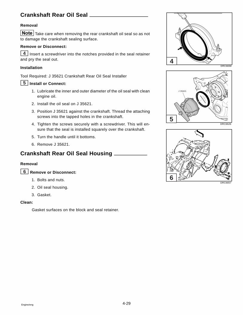
4-29Engine/eng
Crankshaft Rear Oil Seal
Removal
Take care when removing the rear crankshaft oil seal so as notto damage the crankshaft sealing surface.
Remove or Disconnect:
4 Insert a screwdriver into the notches provided in the seal retainerand pry the seal out.
Installation
Tool Required: J 35621 Crankshaft Rear Oil Seal Installer
5 Install or Connect:
1. Lubricate the inner and outer diameter of the oil seal with cleanengine oil.
2. Install the oil seal on J 35621.
3. Position J 35621 against the crankshaft. Thread the attachingscrews into the tapped holes in the crankshaft.
4. Tighten the screws securely with a screwdriver. This will en-sure that the seal is installed squarely over the crankshaft.
5. Turn the handle until it bottoms.
6. Remove J 35621.
Crankshaft Rear Oil Seal Housing
Removal
6 Remove or Disconnect:
1. Bolts and nuts.
2. Oil seal housing.
3. Gasket.
Clean:
Gasket surfaces on the block and seal retainer.
DRC6658
DRC6626
DRC6657
J 35621
4
5
6
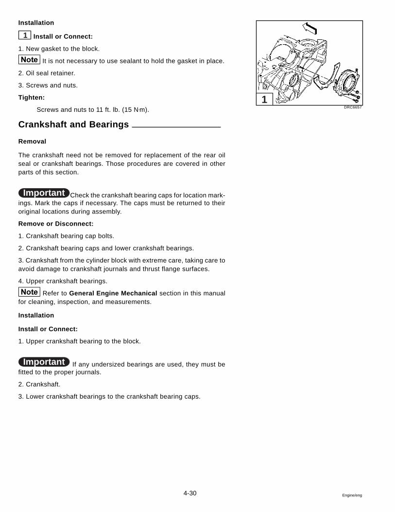
4-30 Engine/eng
Installation
1 Install or Connect:
1. New gasket to the block.
It is not necessary to use sealant to hold the gasket in place.
2. Oil seal retainer.
3. Screws and nuts.
Tighten:
Screws and nuts to 11 ft. lb. (15 N•m).
Crankshaft and Bearings
Removal
The crankshaft need not be removed for replacement of the rear oilseal or crankshaft bearings. Those procedures are covered in otherparts of this section.
Important Check the crankshaft bearing caps for location mark-ings. Mark the caps if necessary. The caps must be returned to theiroriginal locations during assembly.
Remove or Disconnect:
1. Crankshaft bearing cap bolts.
2. Crankshaft bearing caps and lower crankshaft bearings.
3. Crankshaft from the cylinder block with extreme care, taking care toavoid damage to crankshaft journals and thrust flange surfaces.
4. Upper crankshaft bearings.
Refer to General Engine Mechanical section in this manualfor cleaning, inspection, and measurements.
Installation
Install or Connect:
1. Upper crankshaft bearing to the block.
Important If any undersized bearings are used, they must befitted to the proper journals.
2. Crankshaft.
3. Lower crankshaft bearings to the crankshaft bearing caps.
DRC66571
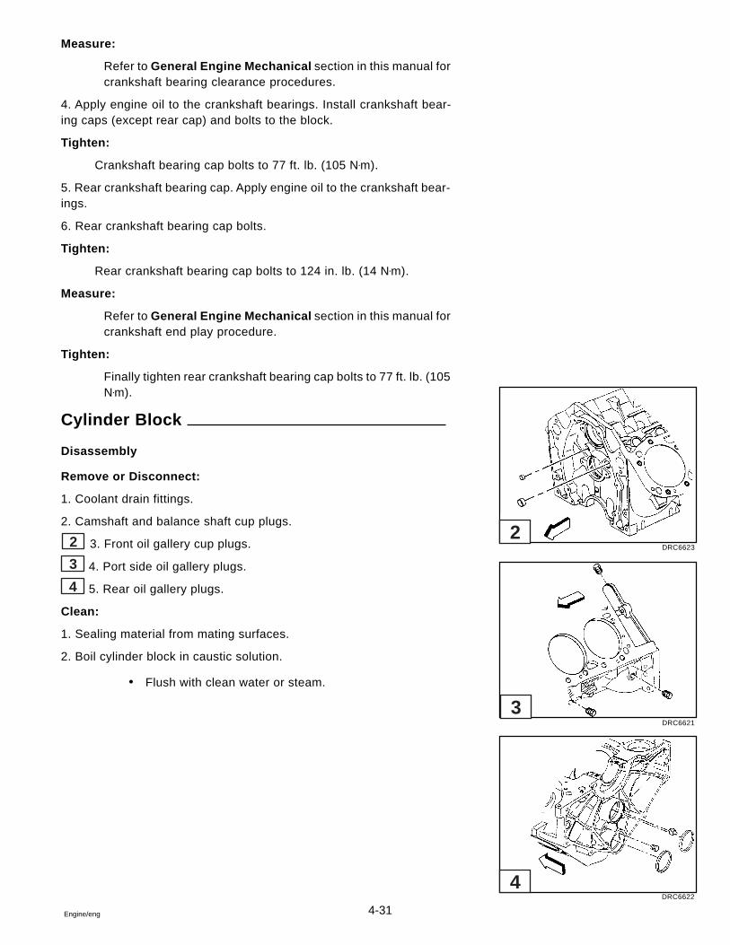
4-31Engine/eng
Measure:
Refer to General Engine Mechanical section in this manual forcrankshaft bearing clearance procedures.
4. Apply engine oil to the crankshaft bearings. Install crankshaft bear-ing caps (except rear cap) and bolts to the block.
Tighten:
Crankshaft bearing cap bolts to 77 ft. lb. (105 N•m).
5. Rear crankshaft bearing cap. Apply engine oil to the crankshaft bear-ings.
6. Rear crankshaft bearing cap bolts.
Tighten:
Rear crankshaft bearing cap bolts to 124 in. lb. (14 N•m).
Measure:
Refer to General Engine Mechanical section in this manual forcrankshaft end play procedure.
Tighten:
Finally tighten rear crankshaft bearing cap bolts to 77 ft. lb. (105N•m).
Cylinder Block
Disassembly
Remove or Disconnect:
1. Coolant drain fittings.
2. Camshaft and balance shaft cup plugs.
2 3. Front oil gallery cup plugs.
3 4. Port side oil gallery plugs.
4 5. Rear oil gallery plugs.
Clean:
1. Sealing material from mating surfaces.
2. Boil cylinder block in caustic solution.
� Flush with clean water or steam.
DRC6623
DRC6621
DRC6622
2
3
4
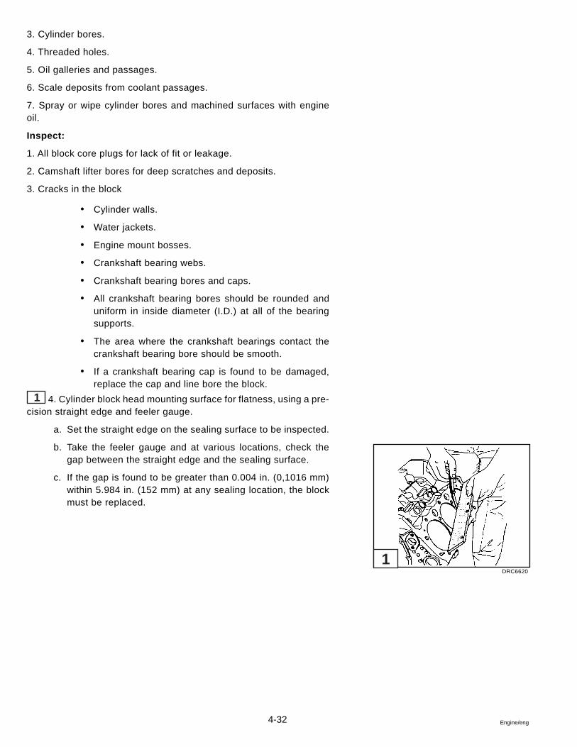
4-32 Engine/eng
3. Cylinder bores.
4. Threaded holes.
5. Oil galleries and passages.
6. Scale deposits from coolant passages.
7. Spray or wipe cylinder bores and machined surfaces with engineoil.
Inspect:
1. All block core plugs for lack of fit or leakage.
2. Camshaft lifter bores for deep scratches and deposits.
3. Cracks in the block
� Cylinder walls.
� Water jackets.
� Engine mount bosses.
� Crankshaft bearing webs.
� Crankshaft bearing bores and caps.
� All crankshaft bearing bores should be rounded anduniform in inside diameter (I.D.) at all of the bearingsupports.
� The area where the crankshaft bearings contact thecrankshaft bearing bore should be smooth.
� If a crankshaft bearing cap is found to be damaged,replace the cap and line bore the block.
1 4. Cylinder block head mounting surface for flatness, using a pre-cision straight edge and feeler gauge.
a. Set the straight edge on the sealing surface to be inspected.
b. Take the feeler gauge and at various locations, check thegap between the straight edge and the sealing surface.
c. If the gap is found to be greater than 0.004 in. (0,1016 mm)within 5.984 in. (152 mm) at any sealing location, the blockmust be replaced.
DRC6620
1
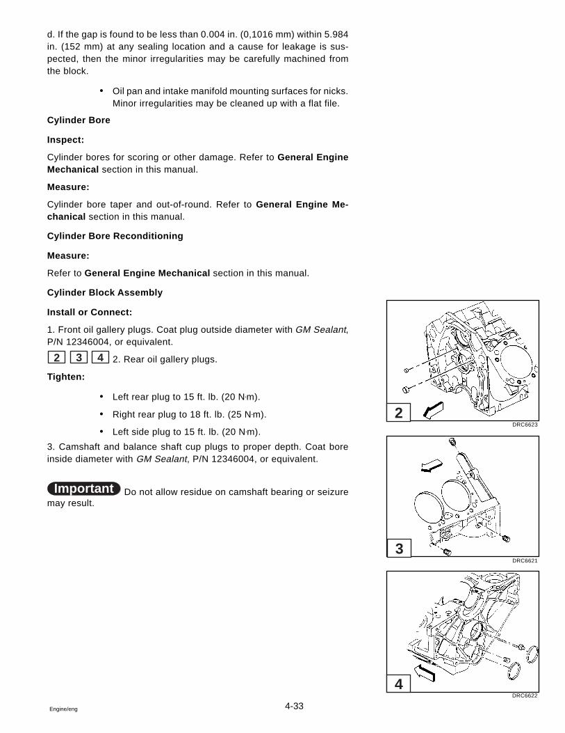
4-33Engine/eng
d. If the gap is found to be less than 0.004 in. (0,1016 mm) within 5.984in. (152 mm) at any sealing location and a cause for leakage is sus-pected, then the minor irregularities may be carefully machined fromthe block.
� Oil pan and intake manifold mounting surfaces for nicks.Minor irregularities may be cleaned up with a flat file.
Cylinder Bore
Inspect:
Cylinder bores for scoring or other damage. Refer to General EngineMechanical section in this manual.
Measure:
Cylinder bore taper and out-of-round. Refer to General Engine Me-chanical section in this manual.
Cylinder Bore Reconditioning
Measure:
Refer to General Engine Mechanical section in this manual.
Cylinder Block Assembly
Install or Connect:
1. Front oil gallery plugs. Coat plug outside diameter with GM Sealant,P/N 12346004, or equivalent.
2 3 4 2. Rear oil gallery plugs.
Tighten:
� Left rear plug to 15 ft. lb. (20 N•m).
� Right rear plug to 18 ft. lb. (25 N•m).
� Left side plug to 15 ft. lb. (20 N•m).
3. Camshaft and balance shaft cup plugs to proper depth. Coat boreinside diameter with GM Sealant, P/N 12346004, or equivalent.
Important Do not allow residue on camshaft bearing or seizuremay result.
DRC6623
DRC6621
DRC6622
2
3
4
4-34 Engine/eng
Circulating Pump
Description
The circulating pump is manufactured specially for marine use. It isserviced only as an assembly. Do not replace with an automotive cir-culating pump.
Inspection
1. Remove alternator and power steering belts.
2. Grasp circulating pump pulley and check end and side play. Turnpulley to check for drag.
3. Look for water leaking from indicator hole beneath pump shaft be-hind pulley, Replace pump if play, drag, or leakage are evident.
Removal and Installation
1. Drain water from block and disconnect water hose from circulatingpump.
2. Remove pulley. Remove circulating pump bolts, pump and gaskets.
3. Use new pump to block gaskets and sealer. Install new pump as-sembly on cylinder block and tighten bolts as specified.
4. Install pulley. Install alternator and power steering belts, then adjusttension.
5. Install hose to circulating pump.
6. Lake or tank test unit and check for leaks.
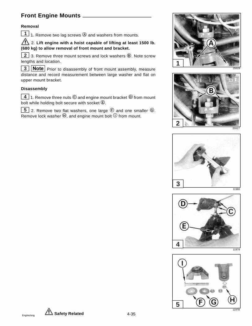
4-35Engine/eng
Front Engine Mounts
Removal
1 1. Remove two lag screws A and washers from mounts.
2. Lift engine with a hoist capable of lifting at least 1500 lb.(680 kg) to allow removal of front mount and bracket.
2 3. Remove three mount screws and lock washers B . Note screwlengths and location.
3 Prior to disassembly of front mount assembly, measuredistance and record measurement between large washer and flat onupper mount bracket.
Disassembly
4 1. Remove three nuts C and engine mount bracket D from mountbolt while holding bolt secure with socket E .
5 2. Remove two flat washers, one large F and one smaller G .Remove lock washer H , and engine mount bolt I from mount.
Safety Related
25929
25917
11980
11979
11978
5
4
3
2
1
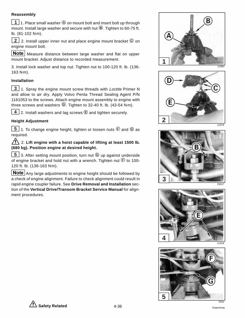
4-36 Engine/eng
Reassembly
1 1. Place small washer A on mount bolt and insert bolt up throughmount. Install large washer and secure with nut B . Tighten to 60-75 ft.lb. (81-102 N•m).
2 2. Install upper inner nut and place engine mount bracket C onengine mount bolt.
Measure distance between large washer and flat on uppermount bracket. Adjust distance to recorded measurement.
3. Install lock washer and top nut. Tighten nut to 100-120 ft. lb. (136-163 N•m).
Installation
3 1. Spray the engine mount screw threads with Loctite Primer Nand allow to air dry. Apply Volvo Penta Thread Sealing Agent P/N1161053 to the screws. Attach engine mount assembly to engine withthree screws and washers D . Tighten to 32-40 ft. lb. (43-54 N•m).
4 2. Install washers and lag screws E and tighten securely.
Height Adjustment
5 1. To change engine height, tighten or loosen nuts F and G asrequired.
2. Lift engine with a hoist capable of lifting at least 1500 lb.(680 kg). Position engine at desired height.
5 3. After setting mount position, turn nut G up against undersideof engine bracket and hold nut with a wrench. Tighten nut F to 100-120 ft. lb. (136-163 N•m).
Any large adjustments to engine height should be followed bya check of engine alignment. Failure to check alignment could result inrapid engine coupler failure. See Drive Removal and Installation sec-tion of the Vertical Drive/Transom Bracket Service Manual for align-ment procedures.
Safety Related
11983
11979
25917
21929
2953
5
4
3
2
1
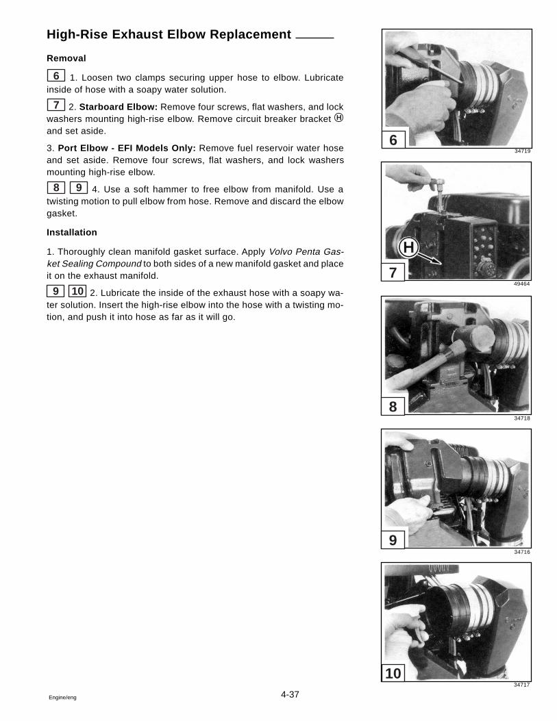
4-37Engine/eng
High-Rise Exhaust Elbow Replacement
Removal
6 1. Loosen two clamps securing upper hose to elbow. Lubricateinside of hose with a soapy water solution.
7 2. Starboard Elbow: Remove four screws, flat washers, and lockwashers mounting high-rise elbow. Remove circuit breaker bracket H
and set aside.
3. Port Elbow - EFI Models Only: Remove fuel reservoir water hoseand set aside. Remove four screws, flat washers, and lock washersmounting high-rise elbow.
8 9 4. Use a soft hammer to free elbow from manifold. Use atwisting motion to pull elbow from hose. Remove and discard the elbowgasket.
Installation
1. Thoroughly clean manifold gasket surface. Apply Volvo Penta Gas-ket Sealing Compound to both sides of a new manifold gasket and placeit on the exhaust manifold.
9 10 2. Lubricate the inside of the exhaust hose with a soapy wa-ter solution. Insert the high-rise elbow into the hose with a twisting mo-tion, and push it into hose as far as it will go.
34719
49464
34718
34716
34717
10
9
8
7
6
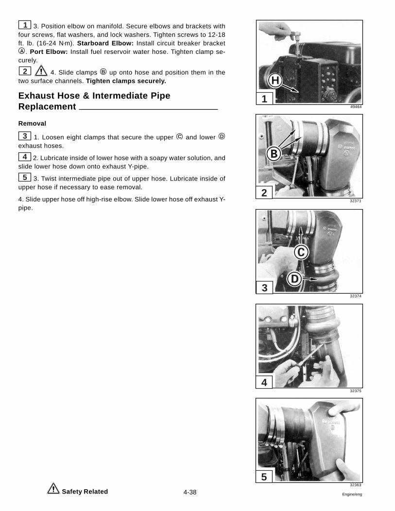
4-38 Engine/eng
1 3. Position elbow on manifold. Secure elbows and brackets withfour screws, flat washers, and lock washers. Tighten screws to 12-18ft. lb. (16-24 N•m). Starboard Elbow: Install circuit breaker bracketA . Port Elbow: Install fuel reservoir water hose. Tighten clamp se-curely.
2 4. Slide clamps B up onto hose and position them in thetwo surface channels. Tighten clamps securely.
Exhaust Hose & Intermediate PipeReplacement
Removal
3 1. Loosen eight clamps that secure the upper C and lower D
exhaust hoses.
4 2. Lubricate inside of lower hose with a soapy water solution, andslide lower hose down onto exhaust Y-pipe.
5 3. Twist intermediate pipe out of upper hose. Lubricate inside ofupper hose if necessary to ease removal.
4. Slide upper hose off high-rise elbow. Slide lower hose off exhaust Y-pipe.
Safety Related
49464
32371
32374
32375
32363
1
2
3
4
5
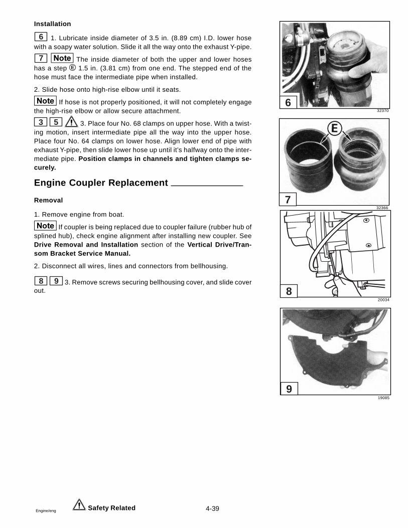
4-39Engine/eng Safety Related
Installation
6 1. Lubricate inside diameter of 3.5 in. (8.89 cm) I.D. lower hosewith a soapy water solution. Slide it all the way onto the exhaust Y-pipe.
7 The inside diameter of both the upper and lower hoseshas a step E 1.5 in. (3.81 cm) from one end. The stepped end of thehose must face the intermediate pipe when installed.
2. Slide hose onto high-rise elbow until it seats.
If hose is not properly positioned, it will not completely engagethe high-rise elbow or allow secure attachment.
3 5 3. Place four No. 68 clamps on upper hose. With a twist-ing motion, insert intermediate pipe all the way into the upper hose.Place four No. 64 clamps on lower hose. Align lower end of pipe withexhaust Y-pipe, then slide lower hose up until it’s halfway onto the inter-mediate pipe. Position clamps in channels and tighten clamps se-curely.
Engine Coupler Replacement
Removal
1. Remove engine from boat.
If coupler is being replaced due to coupler failure (rubber hub ofsplined hub), check engine alignment after installing new coupler. SeeDrive Removal and Installation section of the Vertical Drive/Tran-som Bracket Service Manual.
2. Disconnect all wires, lines and connectors from bellhousing.
8 9 3. Remove screws securing bellhousing cover, and slide coverout.
32370
32366
7
6
20034
19085
8
9
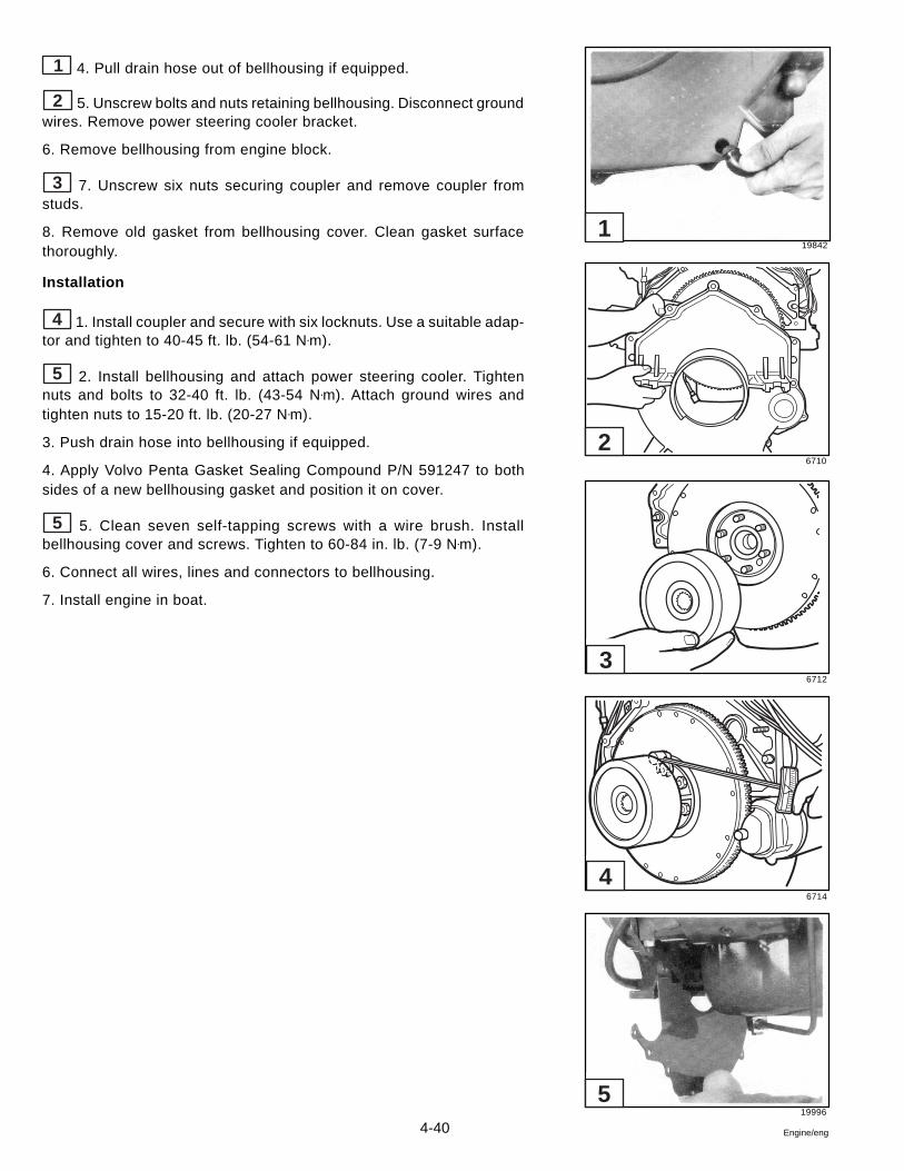
4-40 Engine/eng
1 4. Pull drain hose out of bellhousing if equipped.
2 5. Unscrew bolts and nuts retaining bellhousing. Disconnect groundwires. Remove power steering cooler bracket.
6. Remove bellhousing from engine block.
3 7. Unscrew six nuts securing coupler and remove coupler fromstuds.
8. Remove old gasket from bellhousing cover. Clean gasket surfacethoroughly.
Installation
4 1. Install coupler and secure with six locknuts. Use a suitable adap-tor and tighten to 40-45 ft. lb. (54-61 N•m).
5 2. Install bellhousing and attach power steering cooler. Tightennuts and bolts to 32-40 ft. lb. (43-54 N•m). Attach ground wires andtighten nuts to 15-20 ft. lb. (20-27 N•m).
3. Push drain hose into bellhousing if equipped.
4. Apply Volvo Penta Gasket Sealing Compound P/N 591247 to bothsides of a new bellhousing gasket and position it on cover.
5 5. Clean seven self-tapping screws with a wire brush. Installbellhousing cover and screws. Tighten to 60-84 in. lb. (7-9 N•m).
6. Connect all wires, lines and connectors to bellhousing.
7. Install engine in boat.
19842
6710
6712
6714
19996
1
2
3
4
5
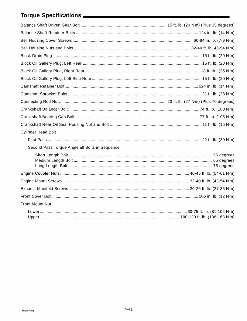
4-41Engine/eng
Torque Specifications
Balance Shaft Driven Gear Bolt ............................................................................ 15 ft. lb. (20 N•m) (Plus 35 degrees)
Balance Shaft Retainer Bolts ............................................................................................................ 124 in. lb. (14 N•m)
Bell Housing Cover Screws .......................................................................................................... 60-84 in. lb. (7-9 N•m)
Bell Housing Nuts and Bolts ....................................................................................................... 32-40 ft. lb. 43-54 N•m)
Block Drain Plug ................................................................................................................................... 15 ft. lb. (20 N•m)
Block Oil Gallery Plug, Left Rear ......................................................................................................... 15 ft. lb. (20 N•m)
Block Oil Gallery Plug, Right Rear ...................................................................................................... 18 ft. lb. (25 N•m)
Block Oil Gallery Plug, Left Side Rear ................................................................................................. 15 ft. lb. (20 N•m)
Camshaft Retainer Bolt ..................................................................................................................... 124 in. lb. (14 N•m)
Camshaft Sprocket Bolts ...................................................................................................................... 21 ft. lb. (28 N•m)
Connecting Rod Nut ............................................................................................... 20 ft. lb. (27 N•m) (Plus 70 degrees)
Crankshaft Balancer Bolt ....................................................................................................................74 ft. lb. (100 N•m)
Crankshaft Bearing Cap Bolt ..............................................................................................................77 ft. lb. (105 N•m)
Crankshaft Rear Oil Seal Housing Nut and Bolt ................................................................................. 11 ft. lb. (15 N•m)
Cylinder Head Bolt
First Pass ........................................................................................................................................ 22 ft. lb. (30 N•m)
Second Pass Torque Angle all Bolts in Sequence:
Short Length Bolt .............................................................................................................................. 55 degreesMedium Length Bolt .......................................................................................................................... 65 degreesLong Length Bolt ............................................................................................................................... 75 degrees
Engine Coupler Nuts .................................................................................................................. 40-45 ft. lb. (54-61 N•m)
Engine Mount Screws ................................................................................................................ 32-40 ft. lb. (43-54 N•m)
Exhaust Manifold Screws .......................................................................................................... 20-26 ft. lb. (27-35 N•m)
Front Cover Bolt ................................................................................................................................. 106 in. lb. (12 N•m)
Front Mount Nut
Lower .................................................................................................................................. 60-75 ft. lb. (81-102 N•m)Upper ........................................................................................................................... 100-120 ft. lb. (136-163 N•m)
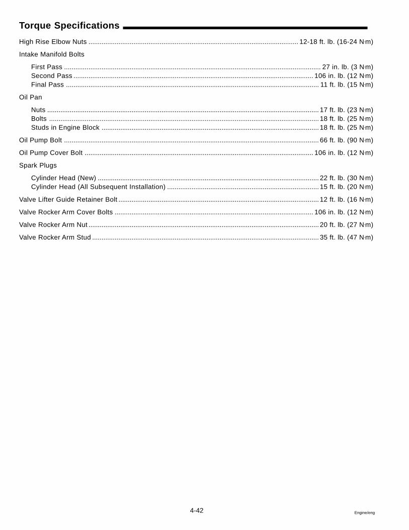
4-42 Engine/eng
Torque Specifications
High Rise Elbow Nuts ................................................................................................................ 12-18 ft. lb. (16-24 N•m)
Intake Manifold Bolts
First Pass ......................................................................................................................................... 27 in. lb. (3 N•m)Second Pass ................................................................................................................................ 106 in. lb. (12 N•m)Final Pass ....................................................................................................................................... 11 ft. lb. (15 N•m)
Oil Pan
Nuts ................................................................................................................................................. 17 ft. lb. (23 N•m)Bolts ................................................................................................................................................ 18 ft. lb. (25 N•m)Studs in Engine Block .................................................................................................................... 18 ft. lb. (25 N•m)
Oil Pump Bolt ........................................................................................................................................ 66 ft. lb. (90 N•m)
Oil Pump Cover Bolt .......................................................................................................................... 106 in. lb. (12 N•m)
Spark Plugs
Cylinder Head (New) ...................................................................................................................... 22 ft. lb. (30 N•m)Cylinder Head (All Subsequent Installation) ................................................................................. 15 ft. lb. (20 N•m)
Valve Lifter Guide Retainer Bolt ........................................................................................................... 12 ft. lb. (16 N•m)
Valve Rocker Arm Cover Bolts .......................................................................................................... 106 in. lb. (12 N•m)
Valve Rocker Arm Nut ........................................................................................................................... 20 ft. lb. (27 N•m)
Valve Rocker Arm Stud ......................................................................................................................... 35 ft. lb. (47 N•m)
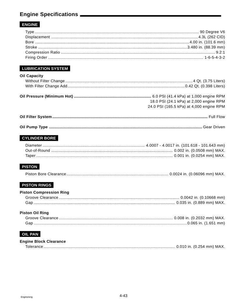
4-43Engine/eng
Engine Specifications
ENGINE
Type ....................................................................................................................................................... 90 Degree V6Displacement ....................................................................................................................................... 4.3L (262 CID)Bore .............................................................................................................................................. 4.00 in. (101.6 mm)Stroke .........................................................................................................................................3.480 in. (88.39 mm)Compression Ratio .............................................................................................................................................. 9.2:1Firing Order ............................................................................................................................................... 1-6-5-4-3-2
LUBRICATION SYSTEM
Oil CapacityWithout Filter Change ..................................................................................................................... 4 Qt. (3.75 Liters)With Filter Change Add............................................................................................................ 0.42 Qt. (0.398 Liters)
Oil Pressure (Minimum Hot) ....................................................................... 6.0 PSI (41.4 kPa) at 1,000 engine RPM18.0 PSI (24.1 kPa) at 2,000 engine RPM
24.0 PSI (165.5 kPa) at 4,000 engine RPM
Oil Filter System ............................................................................................................................................... Full Flow
Oil Pump Type ............................................................................................................................................. Gear Driven
CYLINDER BORE
Diameter .............................................................................................. 4.0007 - 4.0017 in. (101.618 - 101.643 mm)Out-of-Round ................................................................................................................ 0.002 in. (0.0508 mm) MAX.Taper .............................................................................................................................. 0.001 in. (0.0254 mm) MAX.
PISTON
Piston Bore Clearance.............................................................................................. 0.0024 in. (0.06096 mm) MAX.
PISTON RINGS
Piston Compression RingGroove Clearance ............................................................................................................... 0.0042 in. (0.10668 mm)Gap .................................................................................................................................. 0.035 in. (0.889 mm) MAX.
Piston Oil RingGroove Clearance ......................................................................................................... 0.008 in. (0.2032 mm) MAX.Gap .............................................................................................................................................0.065 in. (1.651 mm)
OIL PAN
Engine Block ClearanceTolerance ......................................................................................................................... 0.010 in. (0.254 mm) MAX.
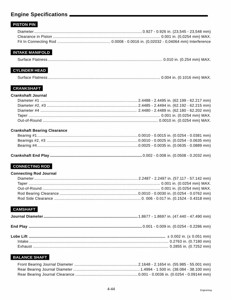
4-44 Engine/eng
Engine Specifications
PISTON PIN
Diameter ...................................................................................................... 0.927 - 0.926 in. (23,545 - 23,548 mm)Clearance in Piston ..................................................................................................... 0.001 in. (0,0254 mm) MAX.Fit In Connecting Rod .................................................. 0.0008 - 0.0016 in. (0,02032 - 0,04064 mm) Interference
INTAKE MANIFOLD
Surface Flatness ............................................................................................................ 0.010 in. (0.254 mm) MAX.
CYLINDER HEAD
Surface Flatness .......................................................................................................... 0.004 in. (0.1016 mm) MAX.
CRANKSHAFT
Crankshaft JournalDiameter #1 ............................................................................................ 2.4488 - 2.4495 in. (62.199 - 62.217 mm)Diameter #2, #3 ...................................................................................... 2.4485 - 2.4494 in. (62.192 - 62.215 mm)Diameter #4 ........................................................................................... 2.4480 - 2.4489 in. (62.180 - 62.202 mm)Taper ............................................................................................................................ 0.001 in. (0.0254 mm) MAX.Out-of-Round ............................................................................................................. 0.0010 in. (0.0254 mm) MAX.
Crankshaft Bearing ClearanceBearing #1 ............................................................................................... 0.0010 - 0.0015 in. (0.0254 - 0.0381 mm)Bearings #2, #3 ...................................................................................... 0.0010 - 0.0025 in. (0.0254 - 0.0635 mm)Bearing #4 ............................................................................................... 0.0025 - 0.0035 in. (0.0635 - 0.0889 mm)
Crankshaft End Play ....................................................................................... 0.002 - 0.008 in. (0.0508 - 0.2032 mm)
CONNECTING ROD
Connecting Rod JournalDiameter .................................................................................................. 2.2487 - 2.2497 in. (57.117 - 57.142 mm)Taper ............................................................................................................................ 0.001 in. (0.0254 mm) MAX.Out-of-Round ............................................................................................................... 0.001 in. (0.0254 mm) MAX.Rod Bearing Clearance .......................................................................... 0.0010 - 0.0030 in. (0.0254 - 0.0762 mm)Rod Side Clearance .................................................................................. 0. 006 - 0.017 in. (0.1524 - 0.4318 mm)
CAMSHAFT
Journal Diameter ......................................................................................... 1.8677 - 1.8697 in. (47.440 - 47.490 mm)
End Play ........................................................................................................... 0.001 - 0.009 in. (0.0254 - 0.2286 mm)
Lobe Lift ................................................................................................................................. ± 0.002 in. (± 0.051 mm)Intake .................................................................................................................................... 0.2763 in. (0.7180 mm)Exhaust ................................................................................................................................ 0.2855 in. (0.7252 mm)
BALANCE SHAFT
Front Bearing Journal Diameter ............................................................ 2.1648 - 2.1654 in. (55.985 - 55.001 mm)Rear Bearing Journal Diameter ............................................................... 1.4994 - 1.500 in. (38.084 - 38.100 mm)Rear Bearing Journal Clearance ........................................................... 0.001 - 0.0036 in. (0.0254 - 0.09144 mm)
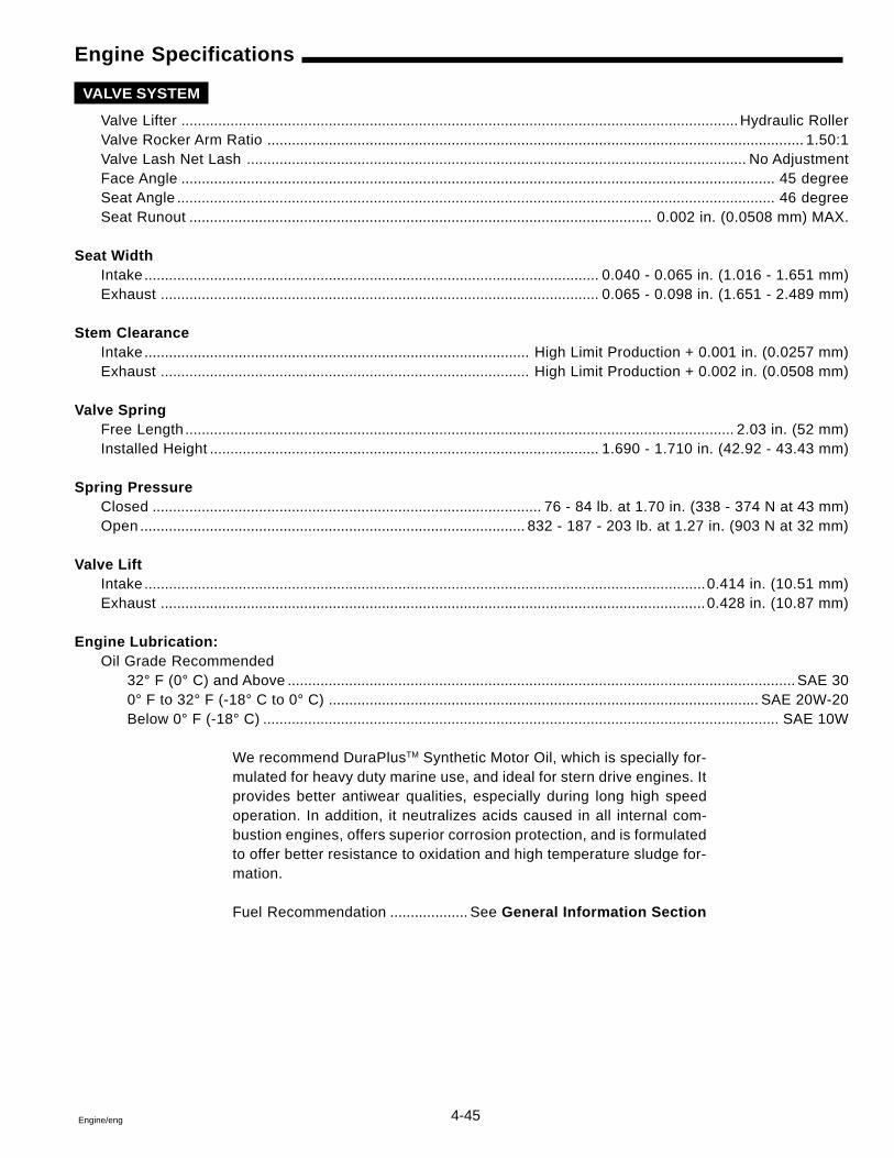
4-45Engine/eng
Engine Specifications
VALVE SYSTEM
Valve Lifter ........................................................................................................................................ Hydraulic RollerValve Rocker Arm Ratio ................................................................................................................................... 1.50:1Valve Lash Net Lash .......................................................................................................................... No AdjustmentFace Angle ................................................................................................................................................. 45 degreeSeat Angle .................................................................................................................................................. 46 degreeSeat Runout ................................................................................................................. 0.002 in. (0.0508 mm) MAX.
Seat WidthIntake ............................................................................................................... 0.040 - 0.065 in. (1.016 - 1.651 mm)Exhaust ........................................................................................................... 0.065 - 0.098 in. (1.651 - 2.489 mm)
Stem ClearanceIntake .............................................................................................. High Limit Production + 0.001 in. (0.0257 mm)Exhaust .......................................................................................... High Limit Production + 0.002 in. (0.0508 mm)
Valve SpringFree Length ...................................................................................................................................... 2.03 in. (52 mm)Installed Height ............................................................................................... 1.690 - 1.710 in. (42.92 - 43.43 mm)
Spring PressureClosed ............................................................................................... 76 - 84 lb. at 1.70 in. (338 - 374 N at 43 mm)Open .............................................................................................. 832 - 187 - 203 lb. at 1.27 in. (903 N at 32 mm)
Valve LiftIntake .........................................................................................................................................0.414 in. (10.51 mm)Exhaust .....................................................................................................................................0.428 in. (10.87 mm)
Engine Lubrication:Oil Grade Recommended
32° F (0° C) and Above ............................................................................................................................ SAE 300° F to 32° F (-18° C to 0° C) ......................................................................................................... SAE 20W-20Below 0° F (-18° C) .............................................................................................................................. SAE 10W
We recommend DuraPlusTM Synthetic Motor Oil, which is specially for-mulated for heavy duty marine use, and ideal for stern drive engines. Itprovides better antiwear qualities, especially during long high speedoperation. In addition, it neutralizes acids caused in all internal com-bustion engines, offers superior corrosion protection, and is formulatedto offer better resistance to oxidation and high temperature sludge for-mation.
Fuel Recommendation ................... See General Information Section
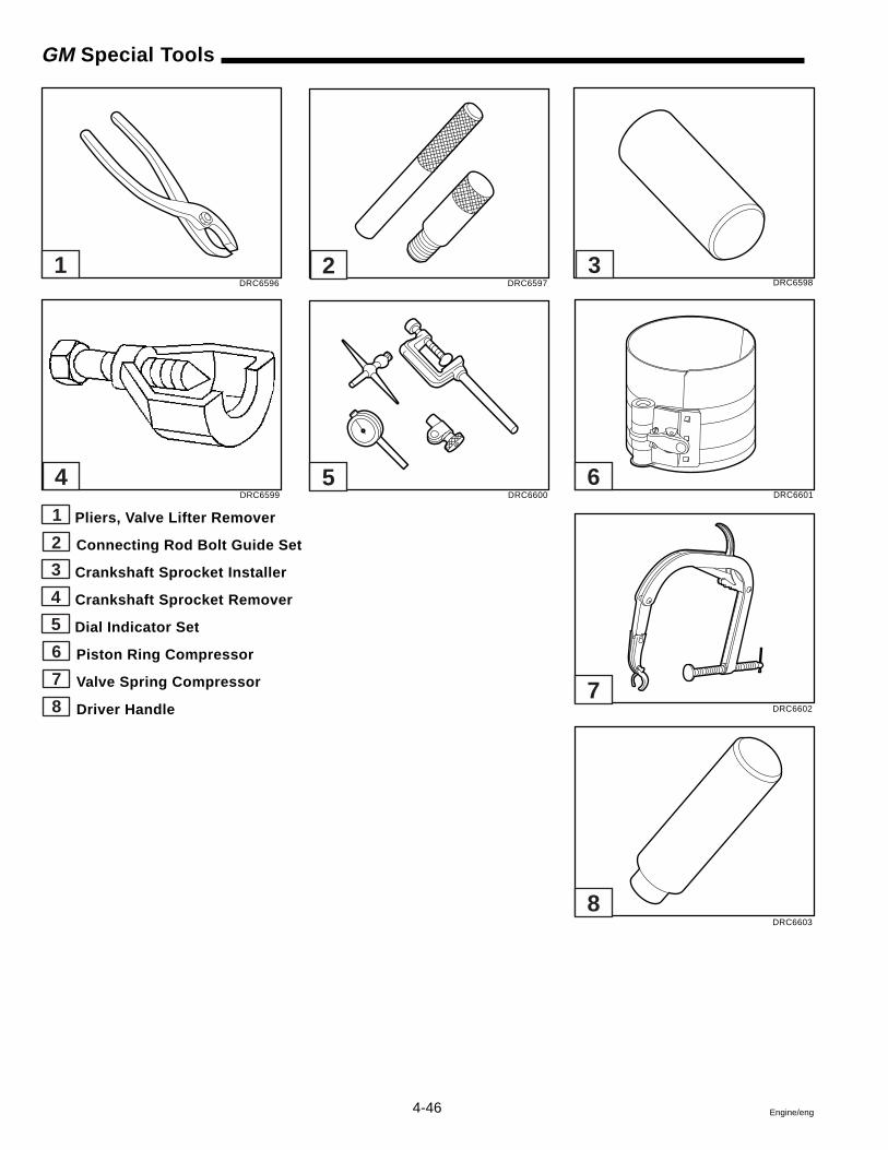
4-46 Engine/eng
GM Special Tools
1 Pliers, Valve Lifter Remover
2 Connecting Rod Bolt Guide Set
3 Crankshaft Sprocket Installer
4 Crankshaft Sprocket Remover
5 Dial Indicator Set
6 Piston Ring Compressor
7 Valve Spring Compressor
8 Driver Handle
DRC6596 DRC6597 DRC6598
DRC6602
DRC6603
DRC6599 DRC6600 DRC6601
1 2 3
4 5 6
7
8
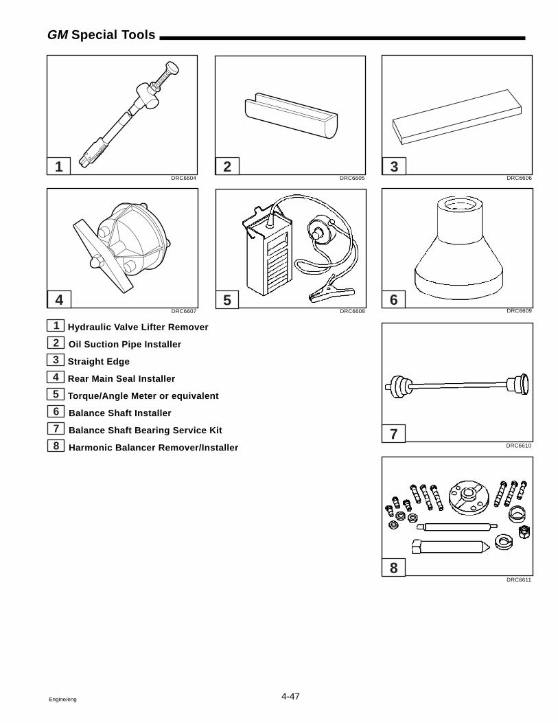
4-47Engine/eng
GM Special Tools
1 Hydraulic Valve Lifter Remover
2 Oil Suction Pipe Installer
3 Straight Edge
4 Rear Main Seal Installer
5 Torque/Angle Meter or equivalent
6 Balance Shaft Installer
7 Balance Shaft Bearing Service Kit
8 Harmonic Balancer Remover/Installer
DRC6604 DRC6605 DRC6606
DRC6610
DRC6611
DRC6607 DRC6608 DRC6609
1 2 3
4 5 6
7
8

4-48 Engine/eng
5-1Engine/eng
Section 55.0 GL and Gi Engines
5.7 GS and GSi Engines
Table of Contents
5
Accessories .............................................................. 5-6Balancer, Crankshaft .............................................. 5-17Camshaft ................................................................. 5-25Circulating Pump.................................................... 5-38Cleaning .................................................................... 5-4Crankshaft and Bearings ....................................... 5-31Cylinder Block ........................................................ 5-35Cylinder Head ......................................................... 5-14Engine
Coupler Replacement ......................................... 5-42Draining ................................................................. 5-6Front Cover .......................................................... 5-23Front Mounts ....................................................... 5-39Lubrication ............................................................ 5-4
ExhaustHigh-Rise Elbow Replacement ........................... 5-40Hose Replacement .............................................. 5-41Manifold ................................................................. 5-7
General Description ................................................. 5-2GM Special Tools .................................................... 5-50Intake Manifold ......................................................... 5-8Intermediate Pipe Replacement ............................ 5-41Material Required ..................................................... 5-3Oil Filter ................................................................... 5-20Oil Pan ..................................................................... 5-18Oil Pump ................................................................. 5-20Pistons and Connecting Rods .............................. 5-27Rear Oil Seal, Crankshaft ...................................... 5-30Rear Oil Seal Housing, Crankshaft ....................... 5-31Rocker Arm Cover .................................................. 5-10Rocker Arm Stud Replacement ............................. 5-15Specifications
Engine .................................................................. 5-46Torque .................................................................. 5-44
Timing Chain and Sprockets ................................. 5-24Tools and Shop Equipment ..................................... 5-6Valve Train .............................................................. 5-11
Safety Warnings
Before working on any part of the engine, read the Safety sectionat the end of this manual.
Always use the correct fastener in the proper location. When youreplace a fastener, use ONLY the exact part number for that appli-cation. The text will call out those fasteners that require replace-ment after removal. The text will also call out the fasteners thatrequire thread lockers or thread sealant.
UNLESS OTHERWISE SPECIFIED, do not use supplement coatings(paints, greases, or other corrosion inhibitors) on threaded fas-teners or fastener joint interfaces. Generally, such coatings ad-versely affect the fastener torque and the joint clamping force,and may damage the fastener.
When you install fasteners, use the correct tightening sequenceand tightening specifications. Following these instructions canhelp you avoid damage to parts and systems.
5-2 Engine/eng
General Description
Cylinder Block
The engine block is made of cast iron and has eight cylinders arrangedin a “V” shape with four cylinders in each bank. It is a one piece cast-ing with the cylinders encircled by coolant jackets.
Cylinder Head
The cylinder heads are cast iron. The valve guides and valve seatsare machined surfaces integral to the head. The spark plugs are lo-cated between the intake and exhaust ports.
Camshaft
A steel camshaft is supported by five bearings pressed into the engineblock. The camshaft sprocket, mounted to the front of the camshaft isdriven by the crankshaft sprocket through a camshaft timing chain.Motion from the camshaft is transmitted to the valves by hydraulic rollervalve lifters, valve push rods, and ball-pivot type rocker arms.
Crankshaft
The crankshaft is made of cast nodular iron. It is supported by fivecrankshaft bearings that are retained by crankshaft bearing caps whichare machined with the block for proper alignment and clearances. Lightduty 5.0L and 5.7L engines have two bolts per cap. Heavy duty 5.7Lengines have four bolts per cap on caps two, three, and four. Thenumber five crankshaft bearing at the rear of the engine is the endthrust bearing. Four connecting rod journals (two rods per journal) arespaced 90 degrees apart.
Pistons and Connecting Rods
The pistons are cast aluminum that use two compression rings andone oil control ring assembly. The piston is a low-friction, lightweightdesign with a flat top and barrel-shaped skirt. The piston pins are chro-mium steel. They have a floating fit in the piston and are retained by apress fit in the connecting rod assembly. The connecting rods are madeout of either forged powdered metal or forged steel. They are machinedwith the rod cap installed for proper clearances and alignment.
Lubrication
The gear-type oil pump is driven through an extension driveshaft. Theextension driveshaft is driven by the distributor which is gear driven bythe camshaft. The oil is drawn from the oil pan through a pickup screenand tube. Pressurized oil is delivered through internal passages tolubricate camshaft and crankshaft bearings and to provide valve lashcontrol in the hydraulic valve lifters. Oil is metered from the valve liftersthrough the valve push rods to lubricate the valve rocker arms and ballpivots. Oil returning to the oil pan from the cylinder heads and the frontcamshaft bearing, lubricates the camshaft timing chain and crankshaftand camshaft sprockets.
5-3Engine/eng
Materials Required
DuraPlusTM Synthetic Motor Oil
Volvo Penta Gasket Sealing Compound
Volvo Penta Thread Sealing Agent
3M Scotch Grip Rubber Adhesive 1300
GM Adhesive, P/N 12346141
GM Engine Oil Supplement, P/N 1052367
GM Sealant, P/N 12346004
GM Threadlock, P/N 12345382
Loctite Primer
Black Neoprene Dip
Valve Train
The valve train is a ball pivot type. Motion is transmitted from thecamshaft through hydraulic roller valve lifters and tubular valve pushrods to the valve rocker arms. The valve rocker arm pivots on a ball toopen the valve. The hydraulic roller valve lifters keep all parts of thevalve train in constant contact.
The valve rocker arm ball is retained on the valve rocker arm stud witha locking nut. The valve rocker arm studs are pressed into the cylinderhead.
Intake Manifold
The intake manifold is a single piece design. It supports either a throttlebody or multiple injectors to meter and distribute fuel to each enginecylinder.
5-4 Engine/eng
Cleaning
Before cleaning the engine, remove the engine accessories to providebetter access to the engine’s exterior surfaces. After removing thethrottle body, distributor, etc., cover the openings with tape to preventthe entry of coolant, solvent, or dirt.
Methods used to clean the engine will depend on what equipment isavailable. Steam cleaning, pressure washing, or solvent cleaning aresome acceptable methods. Allow the engine to dry before beginningthe work.
It is important that the engine be as clean as possible to prevent dirtfrom entering critical areas during disassembly.
Engine Lubrication
1 3 Full pressure lubrication, through a full-flow oil filter issupplied by a gear-type oil pump. Oil is drawn up through the oil pumpscreen and passes through the pump to the oil filter. The oil filter is afull-flow paper element unit with an anti-drain back valve. An oil filterbypass valve is used to ensure adequate oil supply, in the event thefilter becomes plugged or develops excessive pressure drop.
Filtered oil flows into the main gallery and then to the camshaft, rearbearing, and crankshaft bearings. The valve lifter oil gallery suppliesoil to the valve lifters. Oil flows from the valve lifters through the hollowvalve push rods to the valve rocker arms. Oil drains back to the crank-case through oil drain holes in the cylinder head. The camshaft timingchain is drip fed from the front camshaft bearing. The pistons and pis-ton pins are lubricated by oil splash.
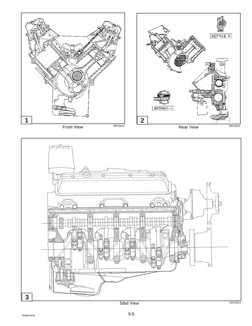
5-5Engine/eng
Front View DRC6612 Rear View DRC6614
Stbd View DRC6613
1 2
3
5-6 Engine/eng
Tools and Shop Equipment
A clean, well lit work area should be available. Other necessary equip-ment includes: a suitable parts cleaning tank, compressed air supply,trays to keep parts and fasteners organized, and an adequate set ofhand tools.
An approved engine repair stand will help prevent personal injury ordamage to engine components.
Special tools are illustrated throughout this section and listed at itsend. These tools (or their equivalents) are specially designed to quicklyand safely accomplish the operations for which they are intended. Theuse of these tools will also minimize possible damage to engine com-ponents.
Some precision measuring tools are required for inspection of certaincritical components. Torque wrenches will be necessary to correctlytighten various fasteners. Those fasteners will be called out within thissection.
Accessories
This manual assumes that the engine accessories have been removed.These accessories may include one or more of the following:
� Power Steering Pump� Alternator� Distributor� Water Supply Pump� Accessory Brackets and Electrical Wiring� Starter Motor
It is beyond the scope of this section to detail the many different ac-cessory installations. Refer to the proper Service Manual for this infor-mation. Diagrams of vacuum hose routing, wiring harness routing, ac-cessory drive belt layout, etc., should be made before removing thesecomponents.
Draining The Engine
Follow the procedures in Section 1, General Information of thismanual to drain crankcase engine oil and the cooling system.
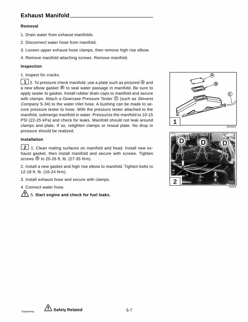
5-7Engine/eng
Exhaust Manifold
Removal
1. Drain water from exhaust manifolds.
2. Disconnect water hose from manifold.
3. Loosen upper exhaust hose clamps, then remove high rise elbow.
4. Remove manifold attaching screws. Remove manifold.
Inspection
1. Inspect for cracks.
1 2. To pressure check manifold, use a plate such as pictured A anda new elbow gasket B to seal water passage in manifold. Be sure toapply sealer to gasket. Install rubber drain caps to manifold and securewith clamps. Attach a Gearcase Pressure Tester C (such as StevensCompany S-34) to the water inlet hose. A bushing can be made to se-cure pressure tester to hose. With the pressure tester attached to themanifold, submerge manifold in water. Pressurize the manifold to 10-15PSI (22-25 kPa) and check for leaks. Manifold should not leak aroundclamps and plate. If so, retighten clamps or reseal plate. No drop inpressure should be realized.
Installation
2 1. Clean mating surfaces on manifold and head. Install new ex-haust gasket, then install manifold and secure with screws. Tightenscrews D to 20-26 ft. lb. (27-35 N•m).
2. Install a new gasket and high rise elbow to manifold. Tighten bolts to12-18 ft. lb. (16-24 N•m).
3. Install exhaust hose and secure with clamps.
4. Connect water hose.
5. Start engine and check for fuel leaks.
Safety Related
DR2642
49463
A
B
C
1
2
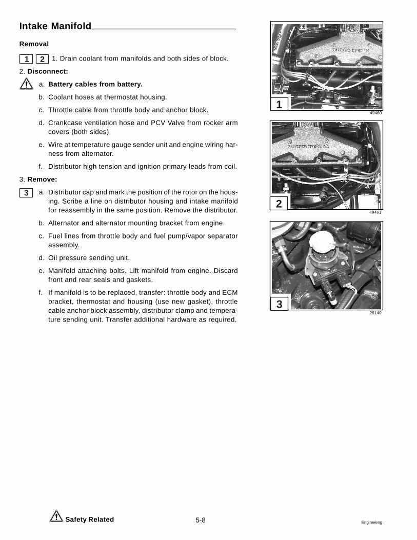
5-8 Engine/eng
Intake Manifold
Removal
1 2 1. Drain coolant from manifolds and both sides of block.
2. Disconnect:
a. Battery cables from battery.
b. Coolant hoses at thermostat housing.
c. Throttle cable from throttle body and anchor block.
d. Crankcase ventilation hose and PCV Valve from rocker armcovers (both sides).
e. Wire at temperature gauge sender unit and engine wiring har-ness from alternator.
f. Distributor high tension and ignition primary leads from coil.
3. Remove:
3 a. Distributor cap and mark the position of the rotor on the hous-ing. Scribe a line on distributor housing and intake manifoldfor reassembly in the same position. Remove the distributor.
b. Alternator and alternator mounting bracket from engine.
c. Fuel lines from throttle body and fuel pump/vapor separatorassembly.
d. Oil pressure sending unit.
e. Manifold attaching bolts. Lift manifold from engine. Discardfront and rear seals and gaskets.
f. If manifold is to be replaced, transfer: throttle body and ECMbracket, thermostat and housing (use new gasket), throttlecable anchor block assembly, distributor clamp and tempera-ture sending unit. Transfer additional hardware as required.
Safety Related
49460
49461
25140
1
2
3
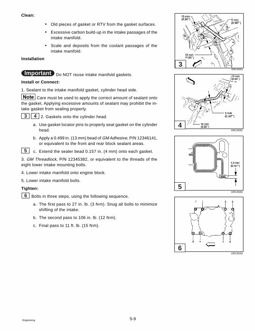
5-9Engine/eng
Clean:
� Old pieces of gasket or RTV from the gasket surfaces.
� Excessive carbon build-up in the intake passages of theintake manifold.
� Scale and deposits from the coolant passages of theintake manifold.
Installation
Important Do NOT reuse intake manifold gaskets.
Install or Connect:
1. Sealant to the intake manifold gasket, cylinder head side.
Care must be used to apply the correct amount of sealant ontothe gasket. Applying excessive amounts of sealant may prohibit the in-take gasket from sealing properly.
3 4 2. Gaskets onto the cylinder head.
a. Use gasket locator pins to properly seat gasket on the cylinderhead.
b. Apply a 0.499 in. (13 mm) bead of GM Adhesive, P/N 12346141,or equivalent to the front and rear block sealant areas.
5 c. Extend the sealer bead 0.157 in. (4 mm) onto each gasket.
3. GM Threadlock, P/N 12345382, or equivalent to the threads of theeight lower intake mounting bolts.
4. Lower intake manifold onto engine block.
5. Lower intake manifold bolts.
Tighten:
6 Bolts in three steps, using the following sequence.
a. The first pass to 27 in. lb. (3 N•m). Snug all bolts to minimizeshifting of the intake.
b. The second pass to 106 in. lb. (12 N•m).
c. Final pass to 11 ft. lb. (15 N•m).
DRC6591
DRC6592
DRC6590
DRC6593
3
4
5
6
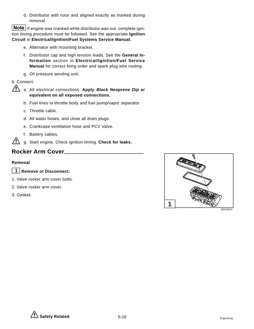
5-10 Engine/eng Safety Related
d. Distributor with rotor and aligned exactly as marked duringremoval.
If engine was cranked while distributor was out, complete igni-tion timing procedure must be followed. See the appropriate IgnitionCircuit in Electrical/Ignition/Fuel Systems Service Manual.
e. Alternator with mounting bracket.
f. Distributor cap and high tension leads. See the General In-formation section in Electrical/Ignition/Fuel ServiceManual for correct firing order and spark plug wire routing.
g. Oil pressure sending unit.
6. Connect:
a. All electrical connections. Apply Black Neoprene Dip orequivalent on all exposed connections.
b. Fuel lines to throttle body and fuel pump/vapor separator.
c. Throttle cable.
d. All water hoses, and close all drain plugs.
e. Crankcase ventilation hose and PCV Valve.
f. Battery cables.
g. Start engine. Check ignition timing. Check for leaks.
Rocker Arm Cover
Removal
1 Remove or Disconnect:
1. Valve rocker arm cover bolts.
2. Valve rocker arm cover.
3. Gasket.
DRC6647
1
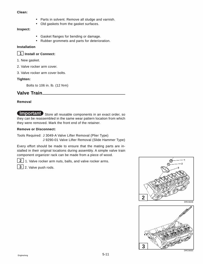
5-11Engine/eng
Clean:
� Parts in solvent. Remove all sludge and varnish.� Old gaskets from the gasket surfaces.
Inspect:
� Gasket flanges for bending or damage.� Rubber grommets and parts for deterioration.
Installation
1 Install or Connect:
1. New gasket.
2. Valve rocker arm cover.
3. Valve rocker arm cover bolts.
Tighten:
Bolts to 106 in. lb. (12 N•m)
Valve Train
Removal
Important Store all reusable components in an exact order, sothey can be reassembled in the same wear pattern location from whichthey were removed. Mark the front end of the retainer.
Remove or Disconnect:
Tools Required: J 3049-A Valve Lifter Removal (Plier Type)J 9290-01 Valve Lifter Removal (Slide Hammer Type)
Every effort should be made to ensure that the mating parts are in-stalled in their original locations during assembly. A simple valve traincomponent organizer rack can be made from a piece of wood.
2 1. Valve rocker arm nuts, balls, and valve rocker arms.
3 2. Valve push rods.
DRC6648
DRC6650
2
3
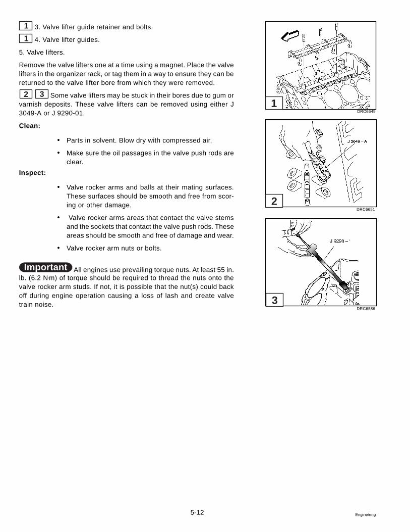
5-12 Engine/eng
1 3. Valve lifter guide retainer and bolts.
1 4. Valve lifter guides.
5. Valve lifters.
Remove the valve lifters one at a time using a magnet. Place the valvelifters in the organizer rack, or tag them in a way to ensure they can bereturned to the valve lifter bore from which they were removed.
2 3 Some valve lifters may be stuck in their bores due to gum orvarnish deposits. These valve lifters can be removed using either J3049-A or J 9290-01.
Clean:
� Parts in solvent. Blow dry with compressed air.
� Make sure the oil passages in the valve push rods areclear.
Inspect:
� Valve rocker arms and balls at their mating surfaces.These surfaces should be smooth and free from scor-ing or other damage.
� Valve rocker arms areas that contact the valve stemsand the sockets that contact the valve push rods. Theseareas should be smooth and free of damage and wear.
� Valve rocker arm nuts or bolts.
Important All engines use prevailing torque nuts. At least 55 in.lb. (6.2 N•m) of torque should be required to thread the nuts onto thevalve rocker arm studs. If not, it is possible that the nut(s) could backoff during engine operation causing a loss of lash and create valvetrain noise.
DRC6649
DRC6651
DRC6586
1
2
3
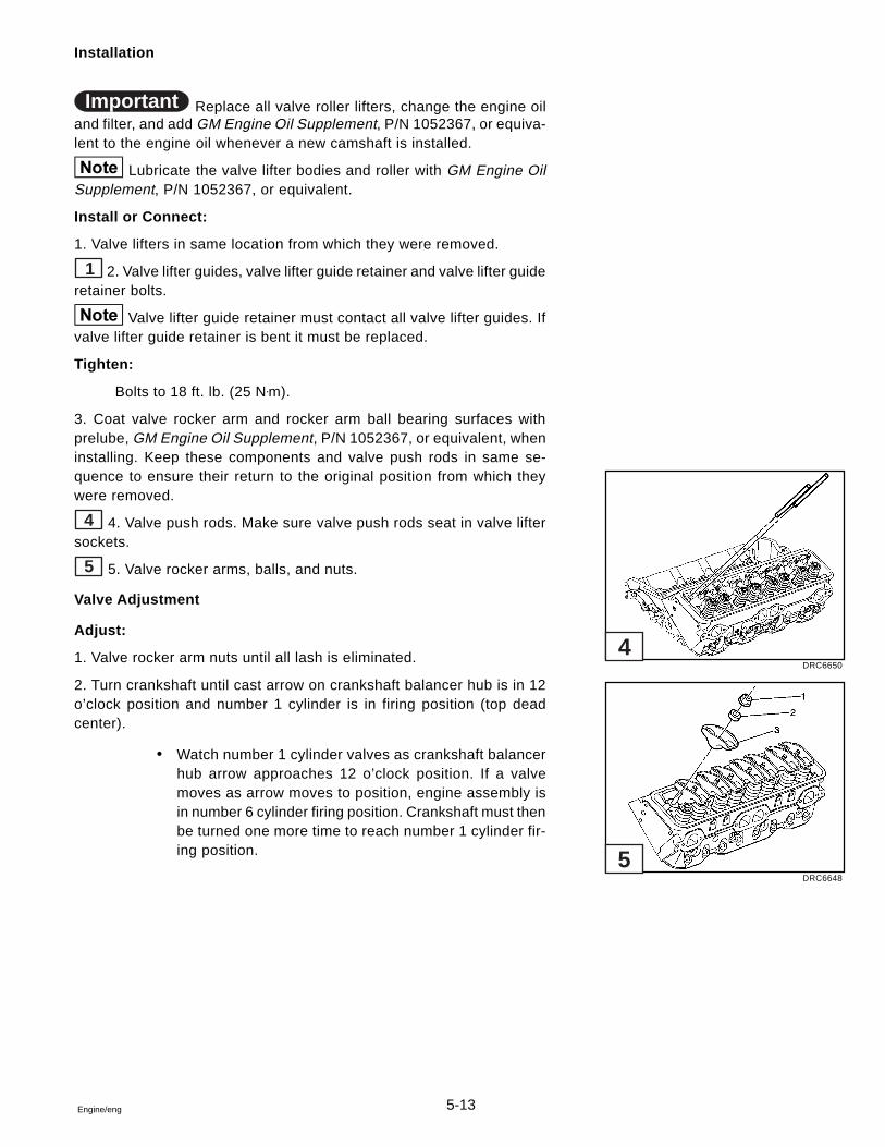
5-13Engine/eng
Installation
Important Replace all valve roller lifters, change the engine oiland filter, and add GM Engine Oil Supplement, P/N 1052367, or equiva-lent to the engine oil whenever a new camshaft is installed.
Lubricate the valve lifter bodies and roller with GM Engine OilSupplement, P/N 1052367, or equivalent.
Install or Connect:
1. Valve lifters in same location from which they were removed.
1 2. Valve lifter guides, valve lifter guide retainer and valve lifter guideretainer bolts.
Valve lifter guide retainer must contact all valve lifter guides. Ifvalve lifter guide retainer is bent it must be replaced.
Tighten:
Bolts to 18 ft. lb. (25 N•m).
3. Coat valve rocker arm and rocker arm ball bearing surfaces withprelube, GM Engine Oil Supplement, P/N 1052367, or equivalent, wheninstalling. Keep these components and valve push rods in same se-quence to ensure their return to the original position from which theywere removed.
4 4. Valve push rods. Make sure valve push rods seat in valve liftersockets.
5 5. Valve rocker arms, balls, and nuts.
Valve Adjustment
Adjust:
1. Valve rocker arm nuts until all lash is eliminated.
2. Turn crankshaft until cast arrow on crankshaft balancer hub is in 12o’clock position and number 1 cylinder is in firing position (top deadcenter).
� Watch number 1 cylinder valves as crankshaft balancerhub arrow approaches 12 o’clock position. If a valvemoves as arrow moves to position, engine assembly isin number 6 cylinder firing position. Crankshaft must thenbe turned one more time to reach number 1 cylinder fir-ing position.
DRC6650
DRC6648
4
5
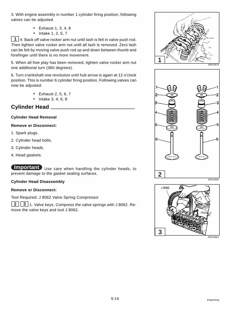
5-14 Engine/eng
3. With engine assembly in number 1 cylinder firing position, followingvalves can be adjusted.
� Exhaust 1, 3, 4, 8� Intake 1, 2, 5, 7
1 4. Back off valve rocker arm nut until lash is felt in valve push rod.Then tighten valve rocker arm nut until all lash is removed. Zero lashcan be felt by moving valve push rod up and down between thumb andforefinger until there is no more movement.
5. When all free play has been removed, tighten valve rocker arm nutone additional turn (360 degrees).
6. Turn crankshaft one revolution until hub arrow is again at 12 o’clockposition. This is number 6 cylinder firing position. Following valves cannow be adjusted:
� Exhaust 2, 5, 6, 7� Intake 3, 4, 6, 8
Cylinder Head
Cylinder Head Removal
Remove or Disconnect:
1. Spark plugs.
2. Cylinder head bolts.
3. Cylinder heads.
4. Head gaskets.
Important Use care when handling the cylinder heads, toprevent damage to the gasket sealing surfaces.
Cylinder Head Disassembly
Remove or Disconnect:
Tool Required: J 8062 Valve Spring Compressor
2 3 1. Valve keys. Compress the valve springs with J 8062. Re-move the valve keys and tool J 8062.
DRC6673
DRC6595
DRC6663
1
2
3
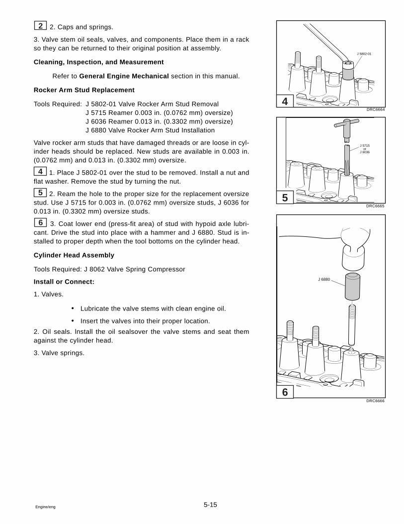
5-15Engine/eng
2 2. Caps and springs.
3. Valve stem oil seals, valves, and components. Place them in a rackso they can be returned to their original position at assembly.
Cleaning, Inspection, and Measurement
Refer to General Engine Mechanical section in this manual.
Rocker Arm Stud Replacement
Tools Required: J 5802-01 Valve Rocker Arm Stud RemovalJ 5715 Reamer 0.003 in. (0.0762 mm) oversize)J 6036 Reamer 0.013 in. (0.3302 mm) oversize)J 6880 Valve Rocker Arm Stud Installation
Valve rocker arm studs that have damaged threads or are loose in cyl-inder heads should be replaced. New studs are available in 0.003 in.(0.0762 mm) and 0.013 in. (0.3302 mm) oversize.
4 1. Place J 5802-01 over the stud to be removed. Install a nut andflat washer. Remove the stud by turning the nut.
5 2. Ream the hole to the proper size for the replacement oversizestud. Use J 5715 for 0.003 in. (0.0762 mm) oversize studs, J 6036 for0.013 in. (0.3302 mm) oversize studs.
6 3. Coat lower end (press-fit area) of stud with hypoid axle lubri-cant. Drive the stud into place with a hammer and J 6880. Stud is in-stalled to proper depth when the tool bottoms on the cylinder head.
Cylinder Head Assembly
Tools Required: J 8062 Valve Spring Compressor
Install or Connect:
1. Valves.
� Lubricate the valve stems with clean engine oil.
� Insert the valves into their proper location.
2. Oil seals. lnstall the oil sealsover the valve stems and seat themagainst the cylinder head.
3. Valve springs.
DRC6664
DRC6665
DRC6666
J 5802-01
J 5715or
J 6036
J 6880
4
5
6
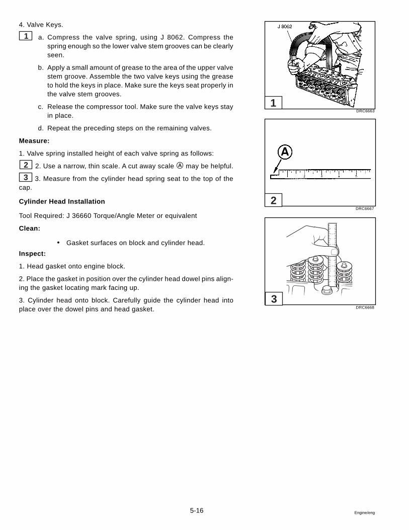
5-16 Engine/eng
4. Valve Keys.
1 a. Compress the valve spring, using J 8062. Compress thespring enough so the lower valve stem grooves can be clearlyseen.
b. Apply a small amount of grease to the area of the upper valvestem groove. Assemble the two valve keys using the greaseto hold the keys in place. Make sure the keys seat properly inthe valve stem grooves.
c. Release the compressor tool. Make sure the valve keys stayin place.
d. Repeat the preceding steps on the remaining valves.
Measure:
1. Valve spring installed height of each valve spring as follows:
2 2. Use a narrow, thin scale. A cut away scale A may be helpful.
3 3. Measure from the cylinder head spring seat to the top of thecap.
Cylinder Head Installation
Tool Required: J 36660 Torque/Angle Meter or equivalent
Clean:
� Gasket surfaces on block and cylinder head.
Inspect:
1. Head gasket onto engine block.
2. Place the gasket in position over the cylinder head dowel pins align-ing the gasket locating mark facing up.
3. Cylinder head onto block. Carefully guide the cylinder head intoplace over the dowel pins and head gasket.
DRC6663
DRC6667
DRC6668
12
54
1
2
3
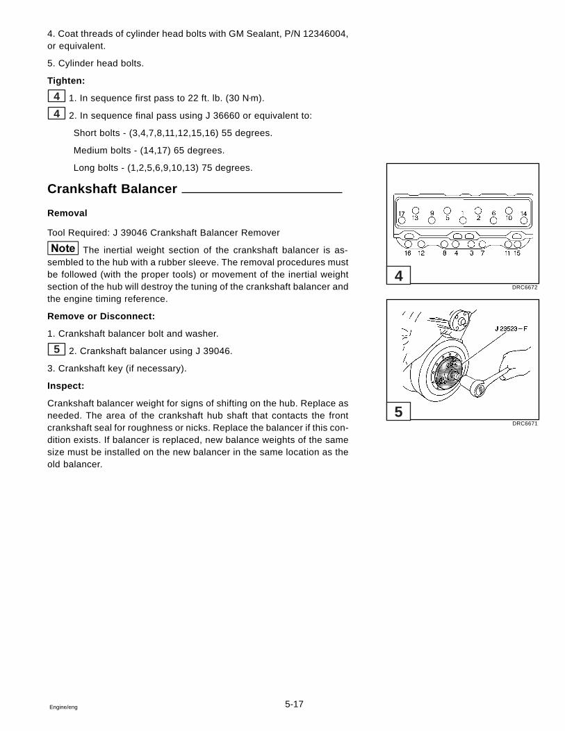
5-17Engine/eng
4. Coat threads of cylinder head bolts with GM Sealant, P/N 12346004,or equivalent.
5. Cylinder head bolts.
Tighten:
4 1. In sequence first pass to 22 ft. lb. (30 N•m).
4 2. In sequence final pass using J 36660 or equivalent to:
Short bolts - (3,4,7,8,11,12,15,16) 55 degrees.
Medium bolts - (14,17) 65 degrees.
Long bolts - (1,2,5,6,9,10,13) 75 degrees.
Crankshaft Balancer
Removal
Tool Required: J 39046 Crankshaft Balancer Remover
The inertial weight section of the crankshaft balancer is as-sembled to the hub with a rubber sleeve. The removal procedures mustbe followed (with the proper tools) or movement of the inertial weightsection of the hub will destroy the tuning of the crankshaft balancer andthe engine timing reference.
Remove or Disconnect:
1. Crankshaft balancer bolt and washer.
5 2. Crankshaft balancer using J 39046.
3. Crankshaft key (if necessary).
Inspect:
Crankshaft balancer weight for signs of shifting on the hub. Replace asneeded. The area of the crankshaft hub shaft that contacts the frontcrankshaft seal for roughness or nicks. Replace the balancer if this con-dition exists. If balancer is replaced, new balance weights of the samesize must be installed on the new balancer in the same location as theold balancer.
DRC6672
DRC6671
4
5
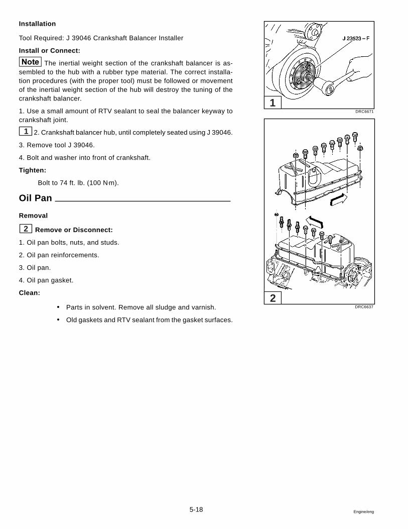
5-18 Engine/eng
Installation
Tool Required: J 39046 Crankshaft Balancer Installer
Install or Connect:
The inertial weight section of the crankshaft balancer is as-sembled to the hub with a rubber type material. The correct installa-tion procedures (with the proper tool) must be followed or movementof the inertial weight section of the hub will destroy the tuning of thecrankshaft balancer.
1. Use a small amount of RTV sealant to seal the balancer keyway tocrankshaft joint.
1 2. Crankshaft balancer hub, until completely seated using J 39046.
3. Remove tool J 39046.
4. Bolt and washer into front of crankshaft.
Tighten:
Bolt to 74 ft. lb. (100 N•m).
Oil Pan
Removal
2 Remove or Disconnect:
1. Oil pan bolts, nuts, and studs.
2. Oil pan reinforcements.
3. Oil pan.
4. Oil pan gasket.
Clean:
� Parts in solvent. Remove all sludge and varnish.
� Old gaskets and RTV sealant from the gasket surfaces.
DRC6671
DRC6637
1
2
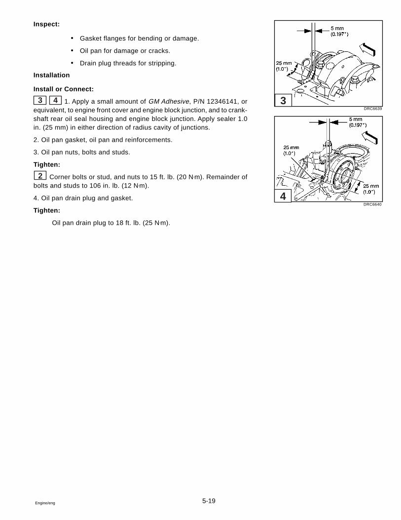
5-19Engine/eng
Inspect:
� Gasket flanges for bending or damage.
� Oil pan for damage or cracks.
� Drain plug threads for stripping.
Installation
Install or Connect:
3 4 1. Apply a small amount of GM Adhesive, P/N 12346141, orequivalent, to engine front cover and engine block junction, and to crank-shaft rear oil seal housing and engine block junction. Apply sealer 1.0in. (25 mm) in either direction of radius cavity of junctions.
2. Oil pan gasket, oil pan and reinforcements.
3. Oil pan nuts, bolts and studs.
Tighten:
2 Corner bolts or stud, and nuts to 15 ft. lb. (20 N•m). Remainder ofbolts and studs to 106 in. lb. (12 N•m).
4. Oil pan drain plug and gasket.
Tighten:
Oil pan drain plug to 18 ft. lb. (25 N•m).
DRC6639
DRC6640
3
4
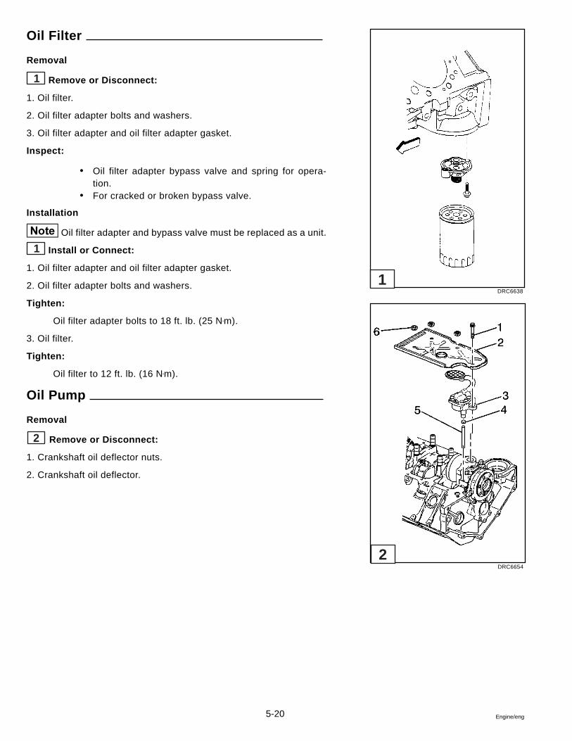
5-20 Engine/eng
Oil Filter
Removal
1 Remove or Disconnect:
1. Oil filter.
2. Oil filter adapter bolts and washers.
3. Oil filter adapter and oil filter adapter gasket.
Inspect:
� Oil filter adapter bypass valve and spring for opera-tion.
� For cracked or broken bypass valve.
Installation
Oil filter adapter and bypass valve must be replaced as a unit.
1 Install or Connect:
1. Oil filter adapter and oil filter adapter gasket.
2. Oil filter adapter bolts and washers.
Tighten:
Oil filter adapter bolts to 18 ft. lb. (25 N•m).
3. Oil filter.
Tighten:
Oil filter to 12 ft. lb. (16 N•m).
Oil Pump
Removal
2 Remove or Disconnect:
1. Crankshaft oil deflector nuts.
2. Crankshaft oil deflector.
DRC6638
DRC6654
1
2
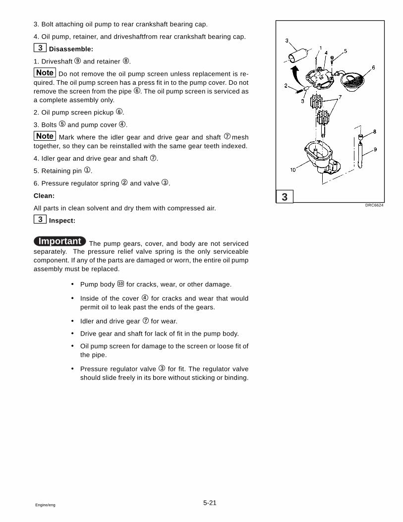
5-21Engine/eng
3. Bolt attaching oil pump to rear crankshaft bearing cap.
4. Oil pump, retainer, and driveshaftfrom rear crankshaft bearing cap.
3 Disassemble:
1. Driveshaft 9 and retainer 8 .
Do not remove the oil pump screen unless replacement is re-quired. The oil pump screen has a press fit in to the pump cover. Do notremove the screen from the pipe 6 . The oil pump screen is serviced asa complete assembly only.
2. Oil pump screen pickup 6 .
3. Bolts 5 and pump cover 4 .
Mark where the idler gear and drive gear and shaft 7 meshtogether, so they can be reinstalled with the same gear teeth indexed.
4. Idler gear and drive gear and shaft 7 .
5. Retaining pin 1 .
6. Pressure regulator spring 2 and valve 3 .
Clean:
All parts in clean solvent and dry them with compressed air.
3 Inspect:
Important The pump gears, cover, and body are not servicedseparately. The pressure relief valve spring is the only serviceablecomponent. If any of the parts are damaged or worn, the entire oil pumpassembly must be replaced.
� Pump body 10 for cracks, wear, or other damage.
� Inside of the cover 4 for cracks and wear that wouldpermit oil to leak past the ends of the gears.
� Idler and drive gear 7 for wear.
� Drive gear and shaft for lack of fit in the pump body.
� Oil pump screen for damage to the screen or loose fit ofthe pipe.
� Pressure regulator valve 3 for fit. The regulator valveshould slide freely in its bore without sticking or binding.
DRC6624
3
5-22 Engine/eng
Assemble:
1 Install or Connect:
1. Pressure regulator valve 3 into the pump cover 4 .
Important Replace the pressure relief valve spring whenreusing the oil pump assembly.
2. Pressure regulator spring 2 into the pump cover 4 .
3. Retaining pin 1 into the pump cover 4 .
4. Drive gear and shaft 7 into the pump body 10 .
5. Idler gear 7 into the pump body 10 .
Match together the index marks on the two gears made duringdisassembly.
6. Pump cover 4 .
Tighten:
Bolts 5 to 106 in. lb. (12 N•m).
7. With the driveshaft 9 installed on the pump, turn the driveshaft byhand to check for smooth operation.
Be careful of twisting, shearing, or collapsing the pipe wheninstalling it to the pump. A damaged pipe can cause lack of lubricationand engine failure.
Oil Pump Screen Installation
Install:
1. Oil pump screen pickup.
a. The oil pump screen assembly should be replaced with a newpart. Loss of press fit condition could result in an air leak andloss of oil pressure.
b. Mount the oil pump in a soft jawed vise.
c. Apply sealer to the end of the pipe.
2 d. Tap the pickup screen and pipe into place, using J 21882and a hammer.
e. The oil pump screen must be parallel with the bottom of theoil pan when installed.
DRC6624
DRC6625
1
2
5-23Engine/eng
Oil Pump Installation
Install:
1 1. Oil pump driveshaft 9 and retainer 8 .
2. Oil pump to the engine.
a. Align the slot in the oil pump shaft with the tang on the dis-tributor shaft.
b. The oil pump should slide easily into place.
c. No gasket is used.
3 3. Oil pump and bolt onto crankshaft bearing cap.
Tighten:
Bolt to 66 ft. lb. (90 N•m).
3 4. Crankshaft oil deflector.
Tighten:
Nuts to 30 ft. lb. (40 N•m).
Engine Front Cover
Removal
4 The composite engine front cover and gasket are NOTREUSABLE.
Remove or Disconnect:
1. Engine front cover bolts.
2. Engine front cover.
Installation
� Lubricate the sealing surface of the crankshaft front oilseal with clean engine oil.
Install or Connect:
A new composite engine front cover and gasket must beinstalled on 5.0L and 5.7L engines. DO NOT reuse the compositeengine front cover.
4 1. Engine front cover and gasket.
DRC6654
DRC6655
3
4
5-24 Engine/eng
2. Install bolts.
Tighten:
Bolts to 106 in. lb. (12 N•m).
Timing Chain and Sprockets
Tool Required: J 5825-A Crankshaft Sprocket Puller
Removal
To prevent damage to pistons or valves, do not turn the crank-shaft after the camshaft timing chain has been removed.
1 Remove or Disconnect:
1. Camshaft sprocket bolts.
2. Camshaft sprocket and camshaft timing chain together.
The sprocket has a light interference fit on the camshaft. Tapthe sprocket on its lower edge to loosen it.
2 3. Crankshaft sprocket using J 5825-A.
4. Key (if damaged).
Inspect:
1. Sprockets for chipped teeth and wear.
Excessively worn sprockets will rapidly wear a new chain.
2. Camshaft timing chain for damage.
An excessively worn chain will rapidly wear a new set of sprock-ets.
3. Crankshaft sprocket for wear in the keyway area.
4. Crankshaft sprocket key for wear.
DRC6656
DRC6615
1
2
5-25Engine/eng
Installation
Tool Required: J 5590 Crankshaft Sprocket Installer
Inspect:
1. Crankshaft key (if removed).
3 2. Crankshaft sprocket using J 5590.
Important Make sure the sprocket alignment mark faces awayfrom the engine block. Make sure the sprocket is fully seated againstthe crank shoulder.
4 3. Camshaft timing chain to the camshaft sprocket.
4 4. Camshaft sprocket and camshaft timing chain to the front ofcamshaft.
Important
• Make sure that camshaft and crankshaft timing marksalign.
The number 6 cylinder is at top dead center of the com-pression stroke with the timing marks in this position.
� Make sure the camshaft dowel pin and camshaft sprock-et hole are properly aligned
� Gears and chain mesh.
5. Camshaft sprocket bolts. Use the bolts to draw the camshaft sprocketonto the camshaft. DO NOT ATTEMPT TO HAMMER THE CAMSHAFTSPROCKET ONTO THE CAMSHAFT. TO DO SO MAY DISLODGE THEREAR CAMSHAFT PLUG AND/OR DAMAGE THE CAMSHAFT.
Tighten:
Bolts to 18 ft. lb. (25 N•m).
Camshaft
Removal
Remove or Disconnect:
All camshaft journals are the same diameter so care must beused in removing the camshaft to avoid damage to the bearings.
5
DRC6669
DRC6633
DRC6670
3
4
5
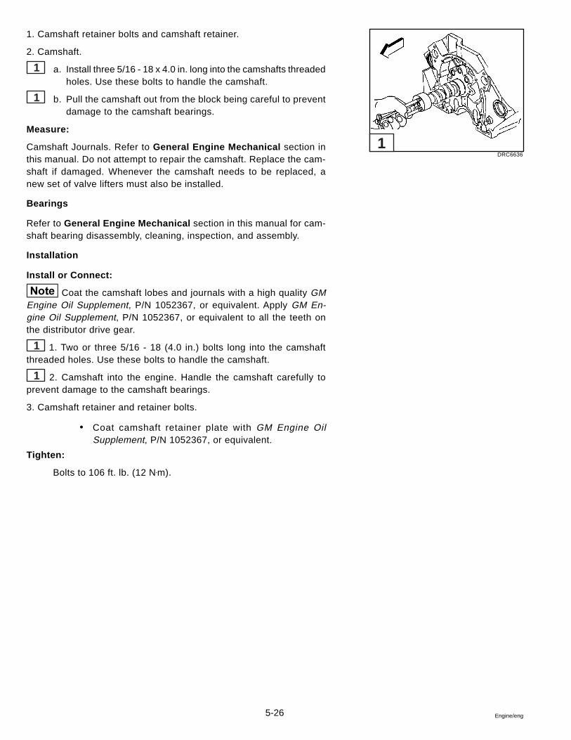
5-26 Engine/eng
1. Camshaft retainer bolts and camshaft retainer.
2. Camshaft.
1 a. Install three 5/16 - 18 x 4.0 in. long into the camshafts threadedholes. Use these bolts to handle the camshaft.
1 b. Pull the camshaft out from the block being careful to preventdamage to the camshaft bearings.
Measure:
Camshaft Journals. Refer to General Engine Mechanical section inthis manual. Do not attempt to repair the camshaft. Replace the cam-shaft if damaged. Whenever the camshaft needs to be replaced, anew set of valve lifters must also be installed.
Bearings
Refer to General Engine Mechanical section in this manual for cam-shaft bearing disassembly, cleaning, inspection, and assembly.
Installation
Install or Connect:
Coat the camshaft lobes and journals with a high quality GMEngine Oil Supplement, P/N 1052367, or equivalent. Apply GM En-gine Oil Supplement, P/N 1052367, or equivalent to all the teeth onthe distributor drive gear.
1 1. Two or three 5/16 - 18 (4.0 in.) bolts long into the camshaftthreaded holes. Use these bolts to handle the camshaft.
1 2. Camshaft into the engine. Handle the camshaft carefully toprevent damage to the camshaft bearings.
3. Camshaft retainer and retainer bolts.
� Coat camshaft retainer plate with GM Engine OilSupplement, P/N 1052367, or equivalent.
Tighten:
Bolts to 106 ft. lb. (12 N•m).
DRC6636
1
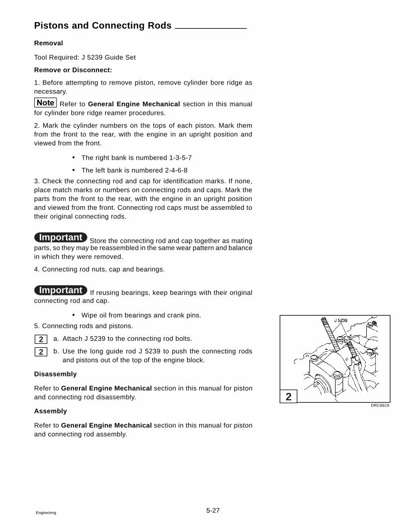
5-27Engine/eng
Pistons and Connecting Rods
Removal
Tool Required: J 5239 Guide Set
Remove or Disconnect:
1. Before attempting to remove piston, remove cylinder bore ridge asnecessary.
Refer to General Engine Mechanical section in this manualfor cylinder bore ridge reamer procedures.
2. Mark the cylinder numbers on the tops of each piston. Mark themfrom the front to the rear, with the engine in an upright position andviewed from the front.
� The right bank is numbered 1-3-5-7
� The left bank is numbered 2-4-6-8
3. Check the connecting rod and cap for identification marks. If none,place match marks or numbers on connecting rods and caps. Mark theparts from the front to the rear, with the engine in an upright positionand viewed from the front. Connecting rod caps must be assembled totheir original connecting rods.
Important Store the connecting rod and cap together as matingparts, so they may be reassembled in the same wear pattern and balancein which they were removed.
4. Connecting rod nuts, cap and bearings.
Important If reusing bearings, keep bearings with their originalconnecting rod and cap.
� Wipe oil from bearings and crank pins.
5. Connecting rods and pistons.
2 a. Attach J 5239 to the connecting rod bolts.
2 b. Use the long guide rod J 5239 to push the connecting rodsand pistons out of the top of the engine block.
Disassembly
Refer to General Engine Mechanical section in this manual for pistonand connecting rod disassembly.
Assembly
Refer to General Engine Mechanical section in this manual for pistonand connecting rod assembly.
DRC6619
2
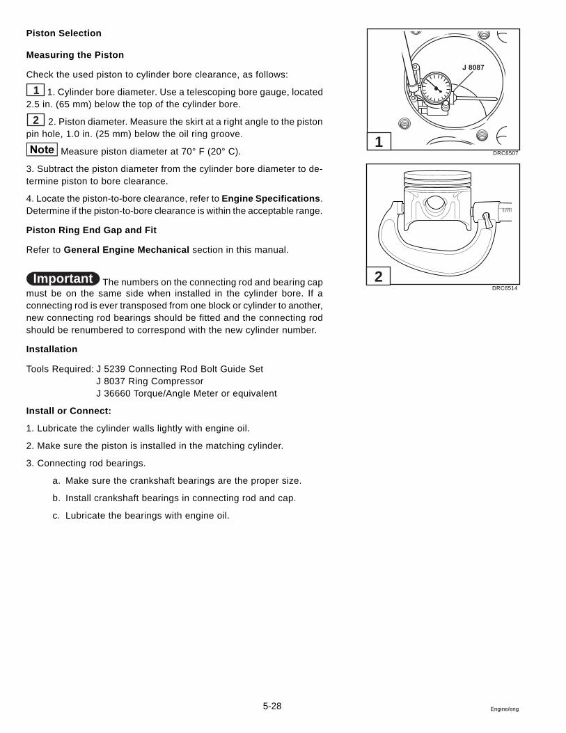
5-28 Engine/eng
Piston Selection
Measuring the Piston
Check the used piston to cylinder bore clearance, as follows:
1 1. Cylinder bore diameter. Use a telescoping bore gauge, located2.5 in. (65 mm) below the top of the cylinder bore.
2 2. Piston diameter. Measure the skirt at a right angle to the pistonpin hole, 1.0 in. (25 mm) below the oil ring groove.
Measure piston diameter at 70° F (20° C).
3. Subtract the piston diameter from the cylinder bore diameter to de-termine piston to bore clearance.
4. Locate the piston-to-bore clearance, refer to Engine Specifications .Determine if the piston-to-bore clearance is within the acceptable range.
Piston Ring End Gap and Fit
Refer to General Engine Mechanical section in this manual.
Important The numbers on the connecting rod and bearing capmust be on the same side when installed in the cylinder bore. If aconnecting rod is ever transposed from one block or cylinder to another,new connecting rod bearings should be fitted and the connecting rodshould be renumbered to correspond with the new cylinder number.
Installation
Tools Required: J 5239 Connecting Rod Bolt Guide SetJ 8037 Ring CompressorJ 36660 Torque/Angle Meter or equivalent
Install or Connect:
1. Lubricate the cylinder walls lightly with engine oil.
2. Make sure the piston is installed in the matching cylinder.
3. Connecting rod bearings.
a. Make sure the crankshaft bearings are the proper size.
b. Install crankshaft bearings in connecting rod and cap.
c. Lubricate the bearings with engine oil.
DRC6507
DRC6514
J 8087
1
2
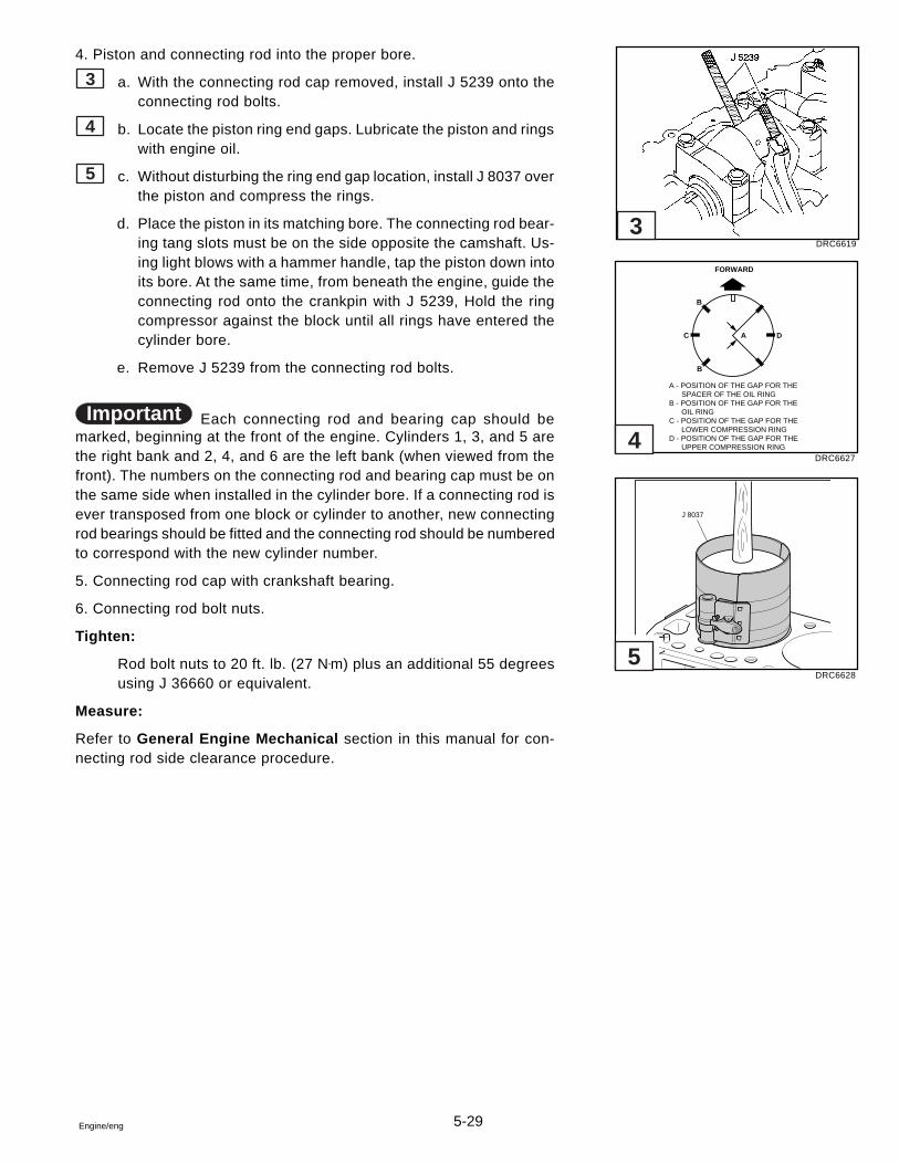
5-29Engine/eng
4. Piston and connecting rod into the proper bore.
3 a. With the connecting rod cap removed, install J 5239 onto theconnecting rod bolts.
4 b. Locate the piston ring end gaps. Lubricate the piston and ringswith engine oil.
5 c. Without disturbing the ring end gap location, install J 8037 overthe piston and compress the rings.
d. Place the piston in its matching bore. The connecting rod bear-ing tang slots must be on the side opposite the camshaft. Us-ing light blows with a hammer handle, tap the piston down intoits bore. At the same time, from beneath the engine, guide theconnecting rod onto the crankpin with J 5239, Hold the ringcompressor against the block until all rings have entered thecylinder bore.
e. Remove J 5239 from the connecting rod bolts.
Important Each connecting rod and bearing cap should bemarked, beginning at the front of the engine. Cylinders 1, 3, and 5 arethe right bank and 2, 4, and 6 are the left bank (when viewed from thefront). The numbers on the connecting rod and bearing cap must be onthe same side when installed in the cylinder bore. If a connecting rod isever transposed from one block or cylinder to another, new connectingrod bearings should be fitted and the connecting rod should be numberedto correspond with the new cylinder number.
5. Connecting rod cap with crankshaft bearing.
6. Connecting rod bolt nuts.
Tighten:
Rod bolt nuts to 20 ft. lb. (27 N•m) plus an additional 55 degreesusing J 36660 or equivalent.
Measure:
Refer to General Engine Mechanical section in this manual for con-necting rod side clearance procedure.
DRC6619
DRC6627
DRC6628
FORWARD
A - POSITION OF THE GAP FOR THE SPACER OF THE OIL RINGB - POSITION OF THE GAP FOR THE OIL RINGC - POSITION OF THE GAP FOR THE LOWER COMPRESSION RINGD - POSITION OF THE GAP FOR THE UPPER COMPRESSION RING
B
B
C A D
J 8037
3
4
5
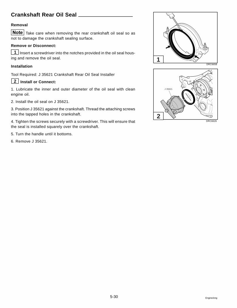
5-30 Engine/eng
Crankshaft Rear Oil Seal
Removal
Take care when removing the rear crankshaft oil seal so asnot to damage the crankshaft sealing surface.
Remove or Disconnect:
1 Insert a screwdriver into the notches provided in the oil seal hous-ing and remove the oil seal.
Installation
Tool Required: J 35621 Crankshaft Rear Oil Seal Installer
2 Install or Connect:
1. Lubricate the inner and outer diameter of the oil seal with cleanengine oil.
2. Install the oil seal on J 35621.
3. Position J 35621 against the crankshaft. Thread the attaching screwsinto the tapped holes in the crankshaft.
4. Tighten the screws securely with a screwdriver. This will ensure thatthe seal is installed squarely over the crankshaft.
5. Turn the handle until it bottoms.
6. Remove J 35621.
DRC6658
DRC6626
J 35621
1
2
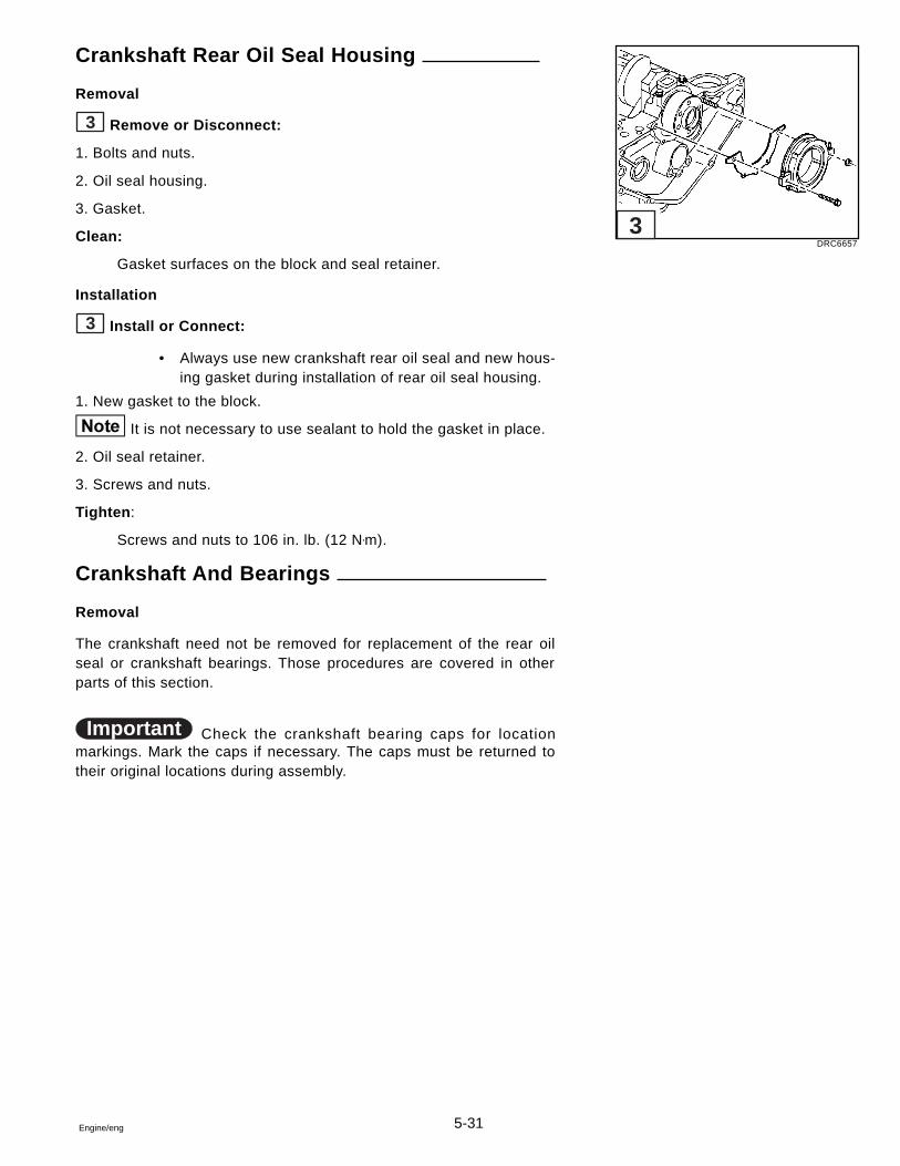
5-31Engine/eng
Crankshaft Rear Oil Seal Housing
Removal
3 Remove or Disconnect:
1. Bolts and nuts.
2. Oil seal housing.
3. Gasket.
Clean:
Gasket surfaces on the block and seal retainer.
Installation
3 Install or Connect:
• Always use new crankshaft rear oil seal and new hous-ing gasket during installation of rear oil seal housing.
1. New gasket to the block.
It is not necessary to use sealant to hold the gasket in place.
2. Oil seal retainer.
3. Screws and nuts.
Tighten :
Screws and nuts to 106 in. lb. (12 N•m).
Crankshaft And Bearings
Removal
The crankshaft need not be removed for replacement of the rear oilseal or crankshaft bearings. Those procedures are covered in otherparts of this section.
Important Check the crankshaft bearing caps for locationmarkings. Mark the caps if necessary. The caps must be returned totheir original locations during assembly.
DRC6657
3
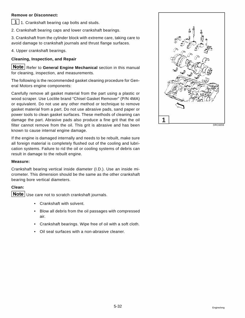
5-32 Engine/eng
Remove or Disconnect:
1 1. Crankshaft bearing cap bolts and studs.
2. Crankshaft bearing caps and lower crankshaft bearings.
3. Crankshaft from the cylinder block with extreme care, taking care toavoid damage to crankshaft journals and thrust flange surfaces.
4. Upper crankshaft bearings.
Cleaning, Inspection, and Repair
Refer to General Engine Mechanical section in this manualfor cleaning, inspection, and measurements.
The following is the recommended gasket cleaning procedure for Gen-eral Motors engine components:
Carefully remove all gasket material from the part using a plastic orwood scraper. Use Loctite brand “Chisel Gasket Remover” (P/N 4MA)or equivalent. Do not use any other method or technique to removegasket material from a part. Do not use abrasive pads, sand paper orpower tools to clean gasket surfaces. These methods of cleaning candamage the part. Abrasive pads also produce a fine grit that the oilfilter cannot remove from the oil. This grit is abrasive and has beenknown to cause internal engine damage.
If the engine is damaged internally and needs to be rebuilt, make sureall foreign material is completely flushed out of the cooling and lubri-cation systems. Failure to rid the oil or cooling systems of debris canresult in damage to the rebuilt engine.
Measure:
Crankshaft bearing vertical inside diameter (I.D.). Use an inside mi-crometer. This dimension should be the same as the other crankshaftbearing bore vertical diameters.
Clean:
Use care not to scratch crankshaft journals.
• Crankshaft with solvent.
• Blow all debris from the oil passages with compressedair.
• Crankshaft bearings. Wipe free of oil with a soft cloth.
• Oil seal surfaces with a non-abrasive cleaner.
DRC6659
1
5-33Engine/eng
Installation
Important Crankshaft bearings are the precision insert type anddo not use shims for adjustment. If clearances are excessive, a newbearing will be required. Service bearings are available in standard sizeand 0.001 in. (0,0254 mm), 0.002 in. (0,0508 mm), 0.010 in. (0,2540mm), and 0.020 in. (0,5080 mm) undersize. Also a 0.009 in. (0,2286mm) is available for 5.7L engines only.
Selective fitting of both connecting rod and crankshaft bearings is nec-essary to obtain close tolerances. For this reason you may use, for ex-ample, one half of a 0.001 in. (0,0254 mm) undersize bearing which willdecrease the clearance 0.0005 in. (0,0127 mm) from using a full stan-dard bearing.
Undersize Crankshaft Journals
When a production crankshaft cannot be precision fit by the methoddescribed previously, it is then ground 0.009 in. (0,2286 mm) under-size. GRIND ONLY THOSE CRANKSHAFT JOURNALS THAT CANNOTBE PROPERLY FITTED. ALL JOURNALS WILL NOT NECESSARILYBE GROUND.
A 0.009 in. (0,2286 mm) undersize bearing or 0.010 in. (0,254 mm)undersize bearing will then be used for precision fitting in the samemanner as previously described.
Oversize Rear Crankshaft Bearing Thrust Faces
Some production engines may have rear crankshaft bearings that are0.008 in. (0,2032 mm) wider than standard across the thrust faces. Thecrankshaft on these engines can be identified by “.008” stamped on therear counterweight. If the rear crankshaft bearings are replaced, theymust have the proper distance between thrust faces to obtain correctcrankshaft end play.
1 Install or Connect:
1. Upper crankshaft bearing to the block.
Important If any undersized bearings are used, they must befitted to the proper journals.
2. Crankshaft.
3. Lower crankshaft bearings to the crankshaft bearing caps.
Measure:
Refer to General Engine Mechanical section in this manual forcrankshaft bearing clearance procedures.
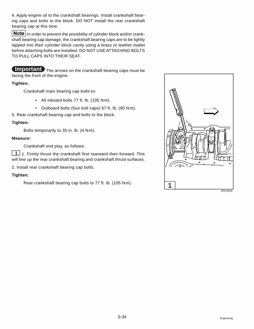
5-34 Engine/eng
4. Apply engine oil to the crankshaft bearings. Install crankshaft bear-ing caps and bolts to the block. DO NOT install the rear crankshaftbearing cap at this time.
In order to prevent the possibility of cylinder block and/or crank-shaft bearing cap damage, the crankshaft bearing caps are to be lightlytapped into their cylinder block cavity using a brass or leather malletbefore attaching bolts are installed. DO NOT USE ATTACHING BOLTSTO PULL CAPS INTO THEIR SEAT.
Important The arrows on the crankshaft bearing caps must befacing the front of the engine.
Tighten:
Crankshaft main bearing cap bolts to:
• All inboard bolts 77 ft. lb. (105 N•m).
• Outboard bolts (four bolt caps) 67 ft. lb. (90 N•m).
5. Rear crankshaft bearing cap and bolts to the block.
Tighten:
Bolts temporarily to 35 in. lb. (4 N•m).
Measure:
Crankshaft end play, as follows:
1 1. Firmly thrust the crankshaft first rearward then forward. Thiswill line up the rear crankshaft bearing and crankshaft thrust surfaces.
2. Install rear crankshaft bearing cap bolts.
Tighten:
Rear crankshaft bearing cap bolts to 77 ft. lb. (105 N•m).
DRC6530
1
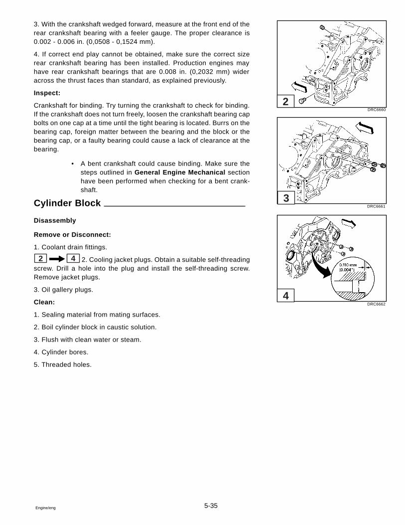
5-35Engine/eng
3. With the crankshaft wedged forward, measure at the front end of therear crankshaft bearing with a feeler gauge. The proper clearance is0.002 - 0.006 in. (0,0508 - 0,1524 mm).
4. If correct end play cannot be obtained, make sure the correct sizerear crankshaft bearing has been installed. Production engines mayhave rear crankshaft bearings that are 0.008 in. (0,2032 mm) wideracross the thrust faces than standard, as explained previously.
Inspect:
Crankshaft for binding. Try turning the crankshaft to check for binding.If the crankshaft does not turn freely, loosen the crankshaft bearing capbolts on one cap at a time until the tight bearing is located. Burrs on thebearing cap, foreign matter between the bearing and the block or thebearing cap, or a faulty bearing could cause a lack of clearance at thebearing.
• A bent crankshaft could cause binding. Make sure thesteps outlined in General Engine Mechanical sectionhave been performed when checking for a bent crank-shaft.
Cylinder Block
Disassembly
Remove or Disconnect:
1. Coolant drain fittings.
2 4 2. Cooling jacket plugs. Obtain a suitable self-threadingscrew. Drill a hole into the plug and install the self-threading screw.Remove jacket plugs.
3. Oil gallery plugs.
Clean:
1. Sealing material from mating surfaces.
2. Boil cylinder block in caustic solution.
3. Flush with clean water or steam.
4. Cylinder bores.
5. Threaded holes.
DRC6660
DRC6661
DRC6662
2
3
4
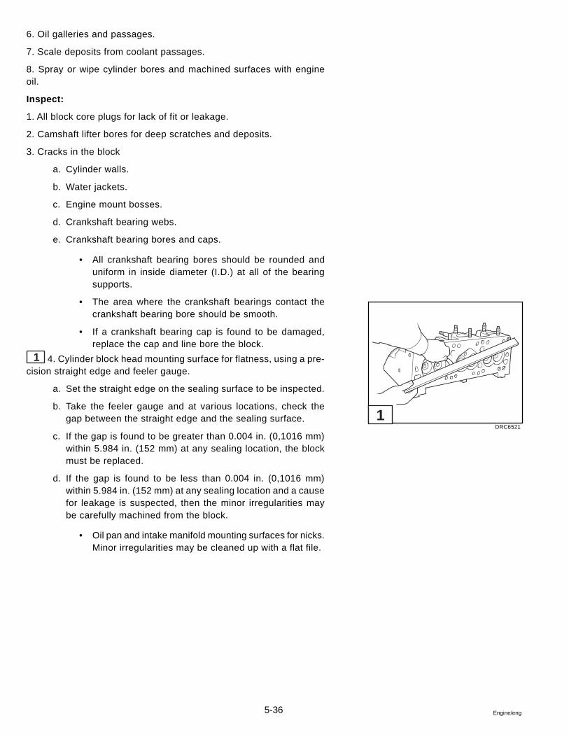
5-36 Engine/eng
6. Oil galleries and passages.
7. Scale deposits from coolant passages.
8. Spray or wipe cylinder bores and machined surfaces with engineoil.
Inspect:
1. All block core plugs for lack of fit or leakage.
2. Camshaft lifter bores for deep scratches and deposits.
3. Cracks in the block
a. Cylinder walls.
b. Water jackets.
c. Engine mount bosses.
d. Crankshaft bearing webs.
e. Crankshaft bearing bores and caps.
• All crankshaft bearing bores should be rounded anduniform in inside diameter (I.D.) at all of the bearingsupports.
• The area where the crankshaft bearings contact thecrankshaft bearing bore should be smooth.
• If a crankshaft bearing cap is found to be damaged,replace the cap and line bore the block.
1 4. Cylinder block head mounting surface for flatness, using a pre-cision straight edge and feeler gauge.
a. Set the straight edge on the sealing surface to be inspected.
b. Take the feeler gauge and at various locations, check thegap between the straight edge and the sealing surface.
c. If the gap is found to be greater than 0.004 in. (0,1016 mm)within 5.984 in. (152 mm) at any sealing location, the blockmust be replaced.
d. If the gap is found to be less than 0.004 in. (0,1016 mm)within 5.984 in. (152 mm) at any sealing location and a causefor leakage is suspected, then the minor irregularities maybe carefully machined from the block.
• Oil pan and intake manifold mounting surfaces for nicks.Minor irregularities may be cleaned up with a flat file.
DRC6521
1
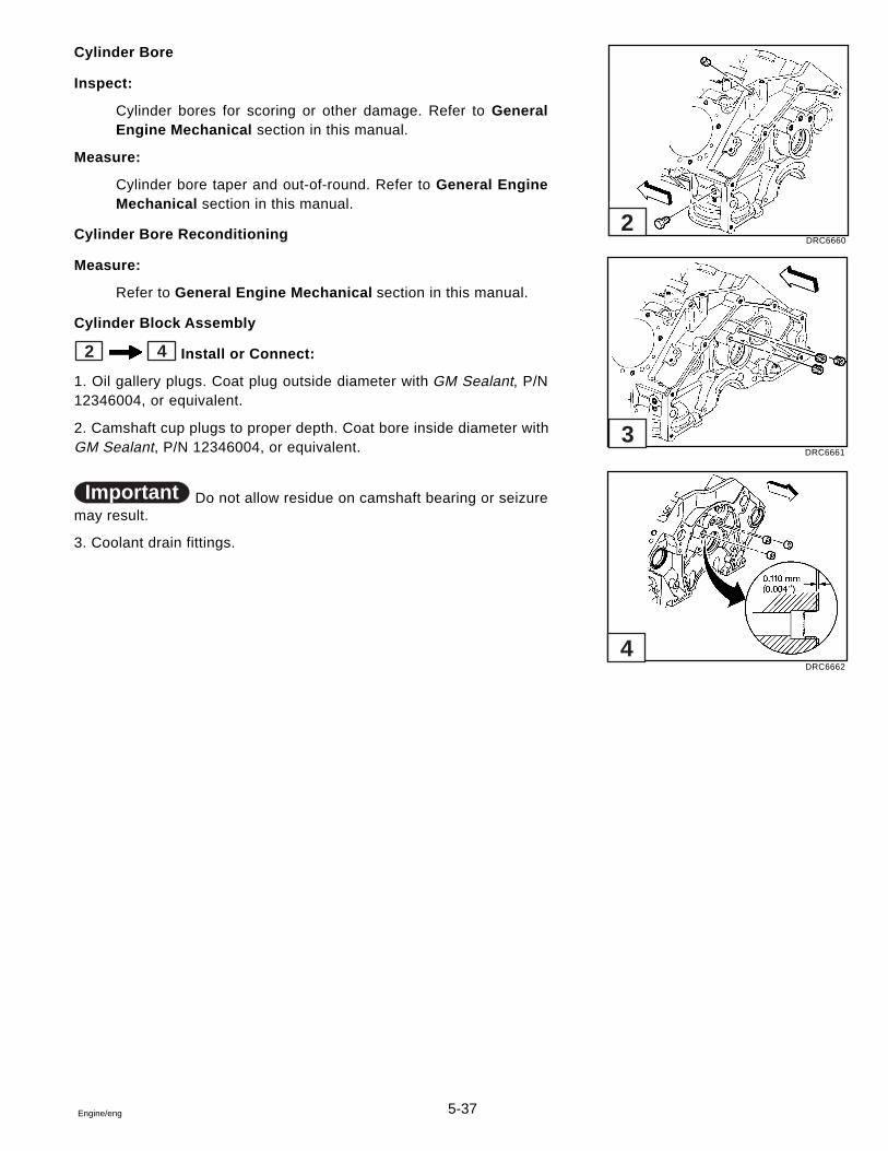
5-37Engine/eng
Cylinder Bore
Inspect:
Cylinder bores for scoring or other damage. Refer to GeneralEngine Mechanical section in this manual.
Measure:
Cylinder bore taper and out-of-round. Refer to General EngineMechanical section in this manual.
Cylinder Bore Reconditioning
Measure:
Refer to General Engine Mechanical section in this manual.
Cylinder Block Assembly
2 4 Install or Connect:
1. Oil gallery plugs. Coat plug outside diameter with GM Sealant, P/N12346004, or equivalent.
2. Camshaft cup plugs to proper depth. Coat bore inside diameter withGM Sealant, P/N 12346004, or equivalent.
Important Do not allow residue on camshaft bearing or seizuremay result.
3. Coolant drain fittings.
DRC6660
DRC6661
DRC6662
2
3
4
5-38 Engine/eng
Circulating Pump
Description
The circulating pump is manufactured specially for marine use. It isserviced only as an assembly. Do not replace with an automotive cir-culating pump.
Inspection
1. Remove alternator and power steering belts.
2. Grasp circulating pump pulley and check end and side play. Turnpulley to check for drag.
3. Look for water leaking from indicator hole beneath pump shaft be-hind pulley. Replace pump if play, drag, or leakage are evident.
Removal and Installation
1. Drain water from block and disconnect water hose from circulatingpump.
2. Remove pulley. Remove circulating pump bolts, pump and gaskets.
3. Use new pump to block gaskets and sealer. Install new pump as-sembly on cylinder block and tighten bolts as specified.
4. Install pulley. Install alternator and power steering belts, then adjusttension.
5. Install drain plugs in block and large hose to circulating pump.
6. Lake or tank test unit and check for leaks.
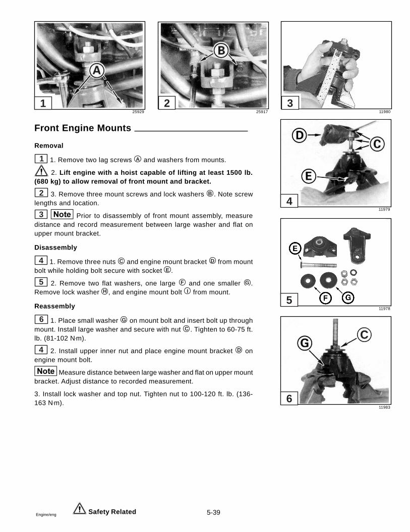
5-39Engine/eng
Front Engine Mounts
Removal
1 1. Remove two lag screws A and washers from mounts.
2. Lift engine with a hoist capable of lifting at least 1500 lb.(680 kg) to allow removal of front mount and bracket.
2 3. Remove three mount screws and lock washers B . Note screwlengths and location.
3 Prior to disassembly of front mount assembly, measuredistance and record measurement between large washer and flat onupper mount bracket.
Disassembly
4 1. Remove three nuts C and engine mount bracket D from mountbolt while holding bolt secure with socket E .
5 2. Remove two flat washers, one large F and one smaller G .Remove lock washer H , and engine mount bolt I from mount.
Reassembly
6 1. Place small washer G on mount bolt and insert bolt up throughmount. Install large washer and secure with nut C . Tighten to 60-75 ft.lb. (81-102 N•m).
4 2. Install upper inner nut and place engine mount bracket D onengine mount bolt.
Measure distance between large washer and flat on upper mountbracket. Adjust distance to recorded measurement.
3. Install lock washer and top nut. Tighten nut to 100-120 ft. lb. (136-163 N•m).
Safety Related
25929 25917 11980
11979
11978
11983
1 2 3
4
5
6
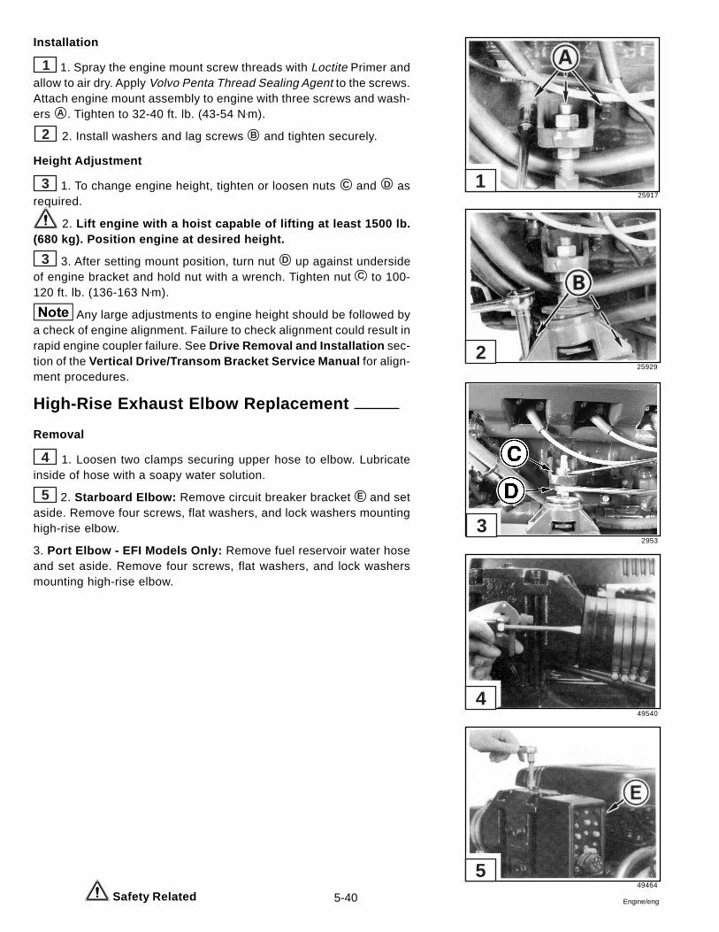
5-40 Engine/eng
Installation
1 1. Spray the engine mount screw threads with Loctite Primer andallow to air dry. Apply Volvo Penta Thread Sealing Agent to the screws.Attach engine mount assembly to engine with three screws and wash-ers A . Tighten to 32-40 ft. lb. (43-54 N•m).
2 2. Install washers and lag screws B and tighten securely.
Height Adjustment
3 1. To change engine height, tighten or loosen nuts C and D asrequired.
2. Lift engine with a hoist capable of lifting at least 1500 lb.(680 kg). Position engine at desired height.
3 3. After setting mount position, turn nut D up against undersideof engine bracket and hold nut with a wrench. Tighten nut C to 100-120 ft. lb. (136-163 N•m).
Any large adjustments to engine height should be followed bya check of engine alignment. Failure to check alignment could result inrapid engine coupler failure. See Drive Removal and Installation sec-tion of the Vertical Drive/Transom Bracket Service Manual for align-ment procedures.
High-Rise Exhaust Elbow Replacement
Removal
4 1. Loosen two clamps securing upper hose to elbow. Lubricateinside of hose with a soapy water solution.
5 2. Starboard Elbow: Remove circuit breaker bracket E and setaside. Remove four screws, flat washers, and lock washers mountinghigh-rise elbow.
3. Port Elbow - EFI Models Only: Remove fuel reservoir water hoseand set aside. Remove four screws, flat washers, and lock washersmounting high-rise elbow.
Safety Related
25917
25929
2953
49540
49464
5
4
3
2
1
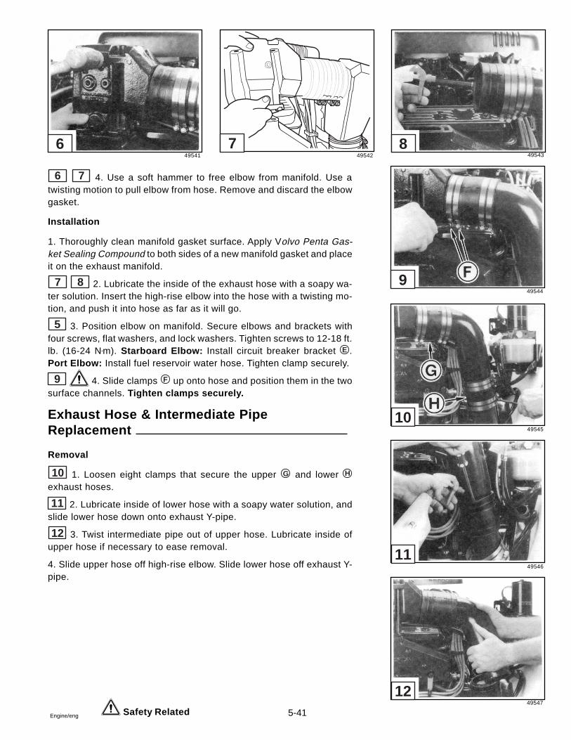
5-41Engine/eng
6 7 4. Use a soft hammer to free elbow from manifold. Use atwisting motion to pull elbow from hose. Remove and discard the elbowgasket.
Installation
1. Thoroughly clean manifold gasket surface. Apply Volvo Penta Gas-ket Sealing Compound to both sides of a new manifold gasket and placeit on the exhaust manifold.
7 8 2. Lubricate the inside of the exhaust hose with a soapy wa-ter solution. Insert the high-rise elbow into the hose with a twisting mo-tion, and push it into hose as far as it will go.
5 3. Position elbow on manifold. Secure elbows and brackets withfour screws, flat washers, and lock washers. Tighten screws to 12-18 ft.lb. (16-24 N•m). Starboard Elbow: Install circuit breaker bracket E .Port Elbow: Install fuel reservoir water hose. Tighten clamp securely.
9 4. Slide clamps F up onto hose and position them in the twosurface channels. Tighten clamps securely.
Exhaust Hose & Intermediate PipeReplacement
Removal
10 1. Loosen eight clamps that secure the upper G and lower H
exhaust hoses.
11 2. Lubricate inside of lower hose with a soapy water solution, andslide lower hose down onto exhaust Y-pipe.
12 3. Twist intermediate pipe out of upper hose. Lubricate inside ofupper hose if necessary to ease removal.
4. Slide upper hose off high-rise elbow. Slide lower hose off exhaust Y-pipe.
Safety Related
49541 49542 49543
49544
49545
49546
49547
12
11
10
9
876
5-42 Engine/eng
20034
19085
6
Installation
1 1. Lubricate inside diameter of 3.5 in. (8.89 cm) I.D. lower hosewith a soapy water solution. Slide it all the way onto the exhaust Y-pipe.
2 The inside diameter of both the upper and lower hoseshas a step A 1.5 in. (3.81 cm) from one end. The stepped end of thehose must face the intermediate pipe when installed.
2. Slide hose onto high-rise elbow until it seats.
If hose is not properly positioned, it will not completely engagethe high-rise elbow or allow secure attachment.
3 4 3. Place four No. 68 clamps on upper hose. With atwisting motion, insert intermediate pipe all the way into the upper hose.Place four No. 64 clamps on lower hose. Align lower end of pipe withexhaust Y-pipe, then slide lower hose up until it’s halfway onto theintermediate pipe. Position clamps in channels and tighten clampssecurely.
Engine Coupler Replacement
Removal
1. Remove engine from boat.
If coupler is being replaced due to coupler failure (rubber hubof splined hub), check engine alignment after installing new coupler.See Drive Removal and Installation section of the Vertical Drive/Transom Bracket Service Manual.
2. Disconnect all wires, lines and connectors from bellhousing.
5 6 3. Remove screws securing bellhousing cover, and slidecover out.
Safety Related
32370 32366 49547
49545
4
321
5
5-43Engine/eng
1 4. Pull drain hose out of bellhousing, if equipped.
2 5. Unscrew bolts and nuts retaining bellhousing. Disconnectground wires. Remove power steering cooler bracket.
6. Remove bellhousing from engine block.
3 7. Unscrew six nuts securing coupler and remove coupler fromstuds.
8. Remove old gasket from bellhousing cover. Clean gasket surfacethoroughly.
Installation
4 1. Install coupler and secure with six locknuts. Use a suitableadaptor and tighten to 40-45 ft. lb. (54-61 N•m).
3 2. Install bellhousing and attach power steering cooler. Tightennuts and bolts to 32-40 ft. lb. (43-54 N•m). Attach ground wires andtighten nuts to 15-20 ft. lb. (20-27 N•m).
3. Push drain hose into bellhousing, if equipped.
4. Apply Volvo Penta Gasket Sealing Compound to both sides of anew belihousing gasket and position it on cover.
5 5. Clean seven self-tapping screws with a wire brush. Installbellhousing cover and screws. Tighten to 60-84 in. lb. (7-9 N•m).
6. Connect all wires, lines and connectors to bellhousing.
7. Install engine in boat.
19842
6710
6712
6714
19996
5
4
3
2
1
5-44 Engine/eng
Torque Specifications - All Models
Bell Housing Cover Screws ....................................................................................................... 60-84 in. lb. (7-9 N•m)
Bell Housing Nuts and Bolts .................................................................................................. 32-40 ft. lb. (43-54 N•m)
Camshaft Retainer Bolt ................................................................................................................... 106 in. lb. (12 N•m)
Camshaft Sprocket Bolt ..................................................................................................................... 18 ft. lb. (25 N•m)
Connecting Rod Nut ........................................................................ 20 ft. lb. (27 N•m) plus an additional 55 degrees
Crankshaft Balancer Bolt ................................................................................................................ 74 ft. Ib. (100 N•m)
Crankshaft Bearing Cap
Inboard Bolt .................................................................................................................................... 77 ft. lb. (105 N•m)Outboard Bolt (Four Bolt Caps) ...................................................................................................... 67 ft. lb. (90 N•m)
Crankshaft Oil Deflector Nut ............................................................................................................. 30 ft. lb. (40 N•m)
Crankshaft Rear Oil Seal Housing Screws and Nuts ................................................................. 106 in. lb. (12 N•m)
Cylinder Head Bolt
First Pass all Bolt in Sequence ....................................................................................................... 22 ft. lb. (30 N•m)Final Pass all Bolts in Sequence:
Short Bolt ........................................................................................................................................... 55 degreesMedium Bolt ....................................................................................................................................... 65 degreesLong Bolt ........................................................................................................................................... 75 degrees
Distributor Clamp Bolt ....................................................................................................................... 18 ft. lb. (25 N•m)
Engine Block
Drain Plug ......................................................................................................................................... 15 ft. lb. (20 N•m)Oil Gallery Plug ................................................................................................................................ 15 ft. lb. (20 N•m)
Engine Coupler Nuts ............................................................................................................... 40-45 ft. Ib. (54-61 N•m)
Engine Mount Screws .............................................................................................................. 32-40 ft. lb. (43-54 N•m)
Exhaust Manifold Screws ....................................................................................................... 20-26 ft. lb. (27-35 N•m)
Front Cover Bolt ............................................................................................................................... 106 in. lb. (12 N•m)
Front Mount
Lower Nut ............................................................................................................................ 60-75 ft. lb. (81-102 N•m)Upper Nut ..................................................................................................................... 100-120 ft. lb. (136-163 N•m)
5-45Engine/eng
Torque Specifications - All Models
Fuel Pump Opening Cover
Upper Bolt ....................................................................................................................................... 30 ft. lb. (40 N•m)
Lower Bolt .................................................................................................................................... 106 in. lb. (12 N•m)Intake Manifold
First Pass ......................................................................................................................................... 27 in. lb. (3 N•m)Second Pass ................................................................................................................................ 106 in. lb. (12 N•m)Final Pass ....................................................................................................................................... 11 ft. Ib. (15 N•m)
Oil Filter Bypass Valve Bolt ............................................................................................................... 20 ft. lb. (26 N•m)
Oil Level Indicator Tube Bolt .......................................................................................................... 106 in. lb. (12 N•m)
Oil Pan
Corner Nut or Stud ......................................................................................................................... 15 ft. lb. (20 N•m)Side Reinforcement Bolt or Stud ................................................................................................ 106 in. lb. (12 N•m)Drain Plug ....................................................................................................................................... 18 ft. lb. (25 N•m)
Oil Filter ................................................................................................................................................ 12 ft. lb. (16 N•m)
Oil Pump
Bolt-to-Rear Crankshaft Bearing Cap ........................................................................................... 66 ft. lb. (90 N•m)Cover Bolt .................................................................................................................................... 106 in. lb. (12 N•m)
Spark Plugs
Spark Plugs (cylinder head - new) ................................................................................................ 22 ft. lb. (30 N•m)
Spark Plugs (cylinder head - all subsequent installations) .......................................................... 15 ft. lb. (20 N•m)
Valve Lifter Guide Retainer Bolt ...................................................................................................... 18 ft. Ib. (25 N•m)
Valve Rocker Arm Cover Bolt ......................................................................................................... 106 in. lb. (12 N•m)
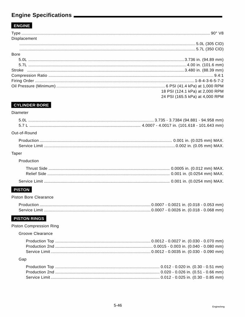
5-46 Engine/eng
Engine Specifications
ENGINE
Type ........................................................................................................................................................................ 90° V8Displacement
............................................................................................................................................................. 5.0L (305 CID)
............................................................................................................................................................. 5.7L (350 CID)Bore
5.0L ...........................................................................................................................................3.736 in. (94.89 mm)5.7L ............................................................................................................................................. 4.00 in. (101.6 mm)
Stroke ............................................................................................................................................3.480 in. (88.39 mm)Compression Ratio ................................................................................................................................................... 9.4:1Firing Order .............................................................................................................................................. 1-8-4-3-6-5-7-2Oil Pressure (Minimum) ................................................................................................. 6 PSI (41.4 kPa) at 1,000 RPM
18 PSI (124.1 kPa) at 2,000 RPM24 PSI (165.5 kPa) at 4,000 RPM
CYLINDER BORE
Diameter
5.0L ................................................................................................................ 3.735 - 3.7384 (94.881 - 94.958 mm)5.7 L ................................................................................................... 4.0007 - 4.0017 in. (101.618 - 101.643 mm)
Out-of-Round
Production ...................................................................................................................... 0.001 in. (0.025 mm) MAX.Service Limit ..................................................................................................................... 0.002 in. (0.05 mm) MAX.
Taper
Production
Thrust Side ............................................................................................................ 0.0005 in. (0.012 mm) MAX.Relief Side ............................................................................................................. 0.001 in. (0.0254 mm) MAX.
Service Limit ................................................................................................................ 0.001 in. (0.0254 mm) MAX.
PISTON
Piston Bore Clearance
Production ................................................................................................... 0.0007 - 0.0021 in. (0.018 - 0.053 mm)Service Limit ............................................................................................... 0.0007 - 0.0026 in. (0.018 - 0.068 mm)
PISTON RINGS
Piston Compression Ring
Groove Clearance
Production Top ..................................................................................... 0.0012 - 0.0027 in. (0.030 - 0.070 mm)Production 2nd ....................................................................................... 0.0015 - 0.003 in. (0.040 - 0.080 mm)Service Limit ......................................................................................... 0.0012 - 0.0035 in. (0.030 - 0.090 mm)
Gap
Production Top ............................................................................................. 0.012 - 0.020 in. (0.30 - 0.51 mm)Production 2nd ............................................................................................. 0.020 - 0.026 in. (0.51 - 0.66 mm)Service Limit ................................................................................................. 0.012 - 0.025 in. (0.30 - 0.85 mm)
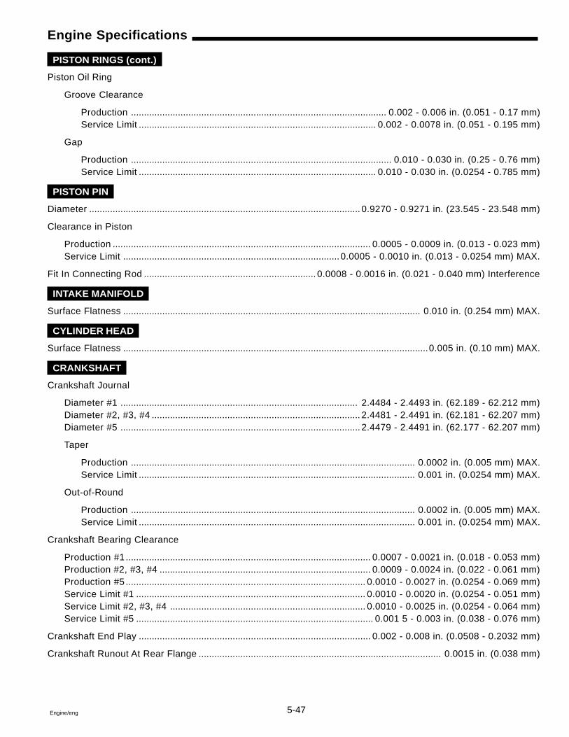
5-47Engine/eng
Engine Specifications
PISTON RINGS (cont.)
Piston Oil Ring
Groove Clearance
Production .................................................................................................. 0.002 - 0.006 in. (0.051 - 0.17 mm)Service Limit ........................................................................................... 0.002 - 0.0078 in. (0.051 - 0.195 mm)
Gap
Production .................................................................................................... 0.010 - 0.030 in. (0.25 - 0.76 mm)Service Limit ........................................................................................... 0.010 - 0.030 in. (0.0254 - 0.785 mm)
PISTON PIN
Diameter ........................................................................................................ 0.9270 - 0.9271 in. (23.545 - 23.548 mm)
Clearance in Piston
Production ................................................................................................... 0.0005 - 0.0009 in. (0.013 - 0.023 mm)Service Limit ................................................................................... 0.0005 - 0.0010 in. (0.013 - 0.0254 mm) MAX.
Fit In Connecting Rod .................................................................. 0.0008 - 0.0016 in. (0.021 - 0.040 mm) Interference
INTAKE MANIFOLD
Surface Flatness .................................................................................................................. 0.010 in. (0.254 mm) MAX.
CYLINDER HEAD
Surface Flatness .....................................................................................................................0.005 in. (0.10 mm) MAX.
CRANKSHAFT
Crankshaft Journal
Diameter #1 ........................................................................................... 2.4484 - 2.4493 in. (62.189 - 62.212 mm)Diameter #2, #3, #4 ................................................................................ 2.4481 - 2.4491 in. (62.181 - 62.207 mm)Diameter #5 ............................................................................................ 2.4479 - 2.4491 in. (62.177 - 62.207 mm)
Taper
Production ............................................................................................................. 0.0002 in. (0.005 mm) MAX.Service Limit .......................................................................................................... 0.001 in. (0.0254 mm) MAX.
Out-of-Round
Production ............................................................................................................. 0.0002 in. (0.005 mm) MAX.Service Limit .......................................................................................................... 0.001 in. (0.0254 mm) MAX.
Crankshaft Bearing Clearance
Production #1.............................................................................................. 0.0007 - 0.0021 in. (0.018 - 0.053 mm)Production #2, #3, #4 ................................................................................. 0.0009 - 0.0024 in. (0.022 - 0.061 mm)Production #5 ............................................................................................ 0.0010 - 0.0027 in. (0.0254 - 0.069 mm)Service Limit #1 ........................................................................................ 0.0010 - 0.0020 in. (0.0254 - 0.051 mm)Service Limit #2, #3, #4 ........................................................................... 0.0010 - 0.0025 in. (0.0254 - 0.064 mm)Service Limit #5 ........................................................................................... 0.001 5 - 0.003 in. (0.038 - 0.076 mm)
Crankshaft End Play ......................................................................................... 0.002 - 0.008 in. (0.0508 - 0.2032 mm)
Crankshaft Runout At Rear Flange ............................................................................................. 0.0015 in. (0.038 mm)
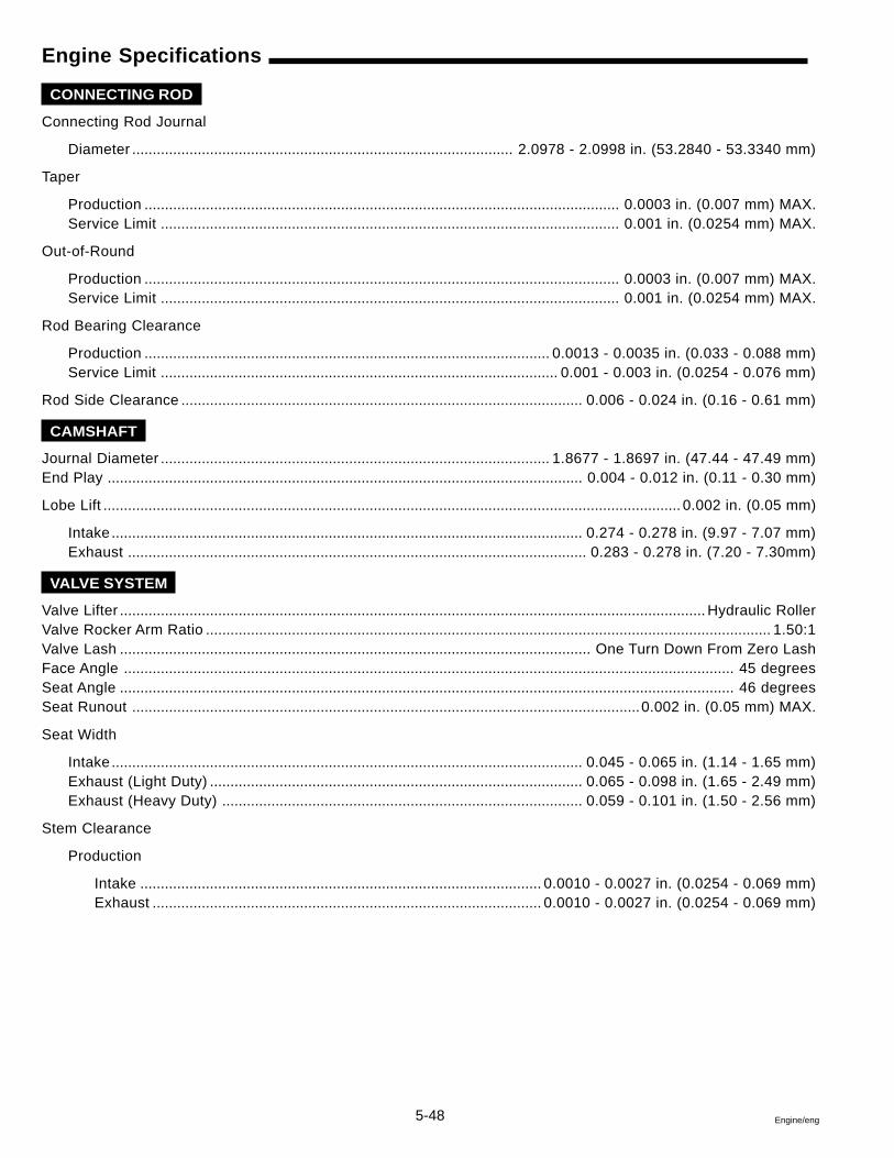
5-48 Engine/eng
Engine Specifications
CONNECTING ROD
Connecting Rod Journal
Diameter ............................................................................................. 2.0978 - 2.0998 in. (53.2840 - 53.3340 mm)
Taper
Production .................................................................................................................... 0.0003 in. (0.007 mm) MAX.Service Limit ................................................................................................................ 0.001 in. (0.0254 mm) MAX.
Out-of-Round
Production .................................................................................................................... 0.0003 in. (0.007 mm) MAX.Service Limit ................................................................................................................ 0.001 in. (0.0254 mm) MAX.
Rod Bearing Clearance
Production ................................................................................................... 0.0013 - 0.0035 in. (0.033 - 0.088 mm)Service Limit ................................................................................................. 0.001 - 0.003 in. (0.0254 - 0.076 mm)
Rod Side Clearance .................................................................................................. 0.006 - 0.024 in. (0.16 - 0.61 mm)
CAMSHAFT
Journal Diameter ............................................................................................... 1.8677 - 1.8697 in. (47.44 - 47.49 mm)End Play .................................................................................................................... 0.004 - 0.012 in. (0.11 - 0.30 mm)
Lobe Lift ............................................................................................................................................. 0.002 in. (0.05 mm)
Intake ................................................................................................................... 0.274 - 0.278 in. (9.97 - 7.07 mm)Exhaust ................................................................................................................ 0.283 - 0.278 in. (7.20 - 7.30mm)
VALVE SYSTEM
Valve Lifter ............................................................................................................................................... Hydraulic RollerValve Rocker Arm Ratio .......................................................................................................................................... 1.50:1Valve Lash ................................................................................................................... One Turn Down From Zero LashFace Angle ..................................................................................................................................................... 45 degreesSeat Angle ...................................................................................................................................................... 46 degreesSeat Runout ............................................................................................................................0.002 in. (0.05 mm) MAX.
Seat Width
Intake ................................................................................................................... 0.045 - 0.065 in. (1.14 - 1.65 mm)Exhaust (Light Duty) ........................................................................................... 0.065 - 0.098 in. (1.65 - 2.49 mm)Exhaust (Heavy Duty) ........................................................................................ 0.059 - 0.101 in. (1.50 - 2.56 mm)
Stem Clearance
Production
Intake .................................................................................................. 0.0010 - 0.0027 in. (0.0254 - 0.069 mm)Exhaust ............................................................................................... 0.0010 - 0.0027 in. (0.0254 - 0.069 mm)
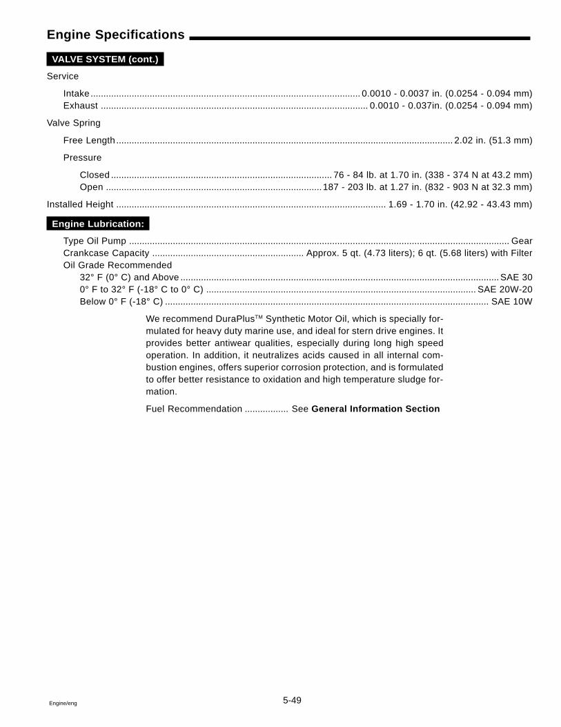
5-49Engine/eng
Engine Specifications
VALVE SYSTEM (cont.)
Service
Intake ......................................................................................................... 0.0010 - 0.0037 in. (0.0254 - 0.094 mm)Exhaust ........................................................................................................ 0.0010 - 0.037in. (0.0254 - 0.094 mm)
Valve Spring
Free Length ................................................................................................................................... 2.02 in. (51.3 mm)
Pressure
Closed ...................................................................................... 76 - 84 lb. at 1.70 in. (338 - 374 N at 43.2 mm)Open .................................................................................... 187 - 203 lb. at 1.27 in. (832 - 903 N at 32.3 mm)
Installed Height ......................................................................................................... 1.69 - 1.70 in. (42.92 - 43.43 mm)
Engine Lubrication:
Type Oil Pump .................................................................................................................................................... GearCrankcase Capacity ........................................................... Approx. 5 qt. (4.73 liters); 6 qt. (5.68 liters) with FilterOil Grade Recommended
32° F (0° C) and Above ............................................................................................................................ SAE 300° F to 32° F (-18° C to 0° C) ......................................................................................................... SAE 20W-20Below 0° F (-18° C) .............................................................................................................................. SAE 10W
We recommend DuraPlusTM Synthetic Motor Oil, which is specially for-mulated for heavy duty marine use, and ideal for stern drive engines. Itprovides better antiwear qualities, especially during long high speedoperation. In addition, it neutralizes acids caused in all internal com-bustion engines, offers superior corrosion protection, and is formulatedto offer better resistance to oxidation and high temperature sludge for-mation.
Fuel Recommendation ................. See General Information Section
5-50 Engine/eng
GM Special Tools
1 Rocker Arm Stud Bore Reamer 0.003 in. (0,0762 mm) O.S.
2 Rocker Arm Stud Bore Reamer 0.013 in. (0,3302 mm) O.S.
3 Rocker Arm Stud Remover
4 Rocker Arm Stud Installer
5 Piston Pin Remover / Installer
6 Cylinder Bore Ridge Reamer
7 Front Cover Aligner / Oil Seal Installer
8 Crankshaft Rear Oil Seal Installer
9 Torque Angle Meter or equivalent
10 Crankshaft Balancer Remover / Installer
DRC6674 DRC6675 DRC6676
DRC6611
DRC6677 DRC6579 DRC6582
DRC6678 DRC6607 DRC6608
1 2 3
4 5 6
7 8 9
10
5-51Engine/eng
GM Special Tools
1 Valve Lifter Remover (plier type)
2 Connecting Rod Guide Tool
3 Crankshaft Sprocket Installer
4 Crankshaft Sprocket Remover
5 Piston Ring Compressor
6 Valve Spring Compressor
7 Carbon Removal Brush
8 Valve Lifter Remover (slide hammer type)
9 Oil Pump Screen Installer
10 Vacuum Pump
DRC6596 DRC6597 DRC6598
DRC6681
DRC6599 DRC6601 DRC6602
DRC6680 DRC6604 DRC6605
1 2 3
4 5 6
7 8 9
10

5-52 Engine/eng
6-1Engine/eng
Section 67.4 Gi Engines
Table of Contents
CamshaftInstallation ........................................................... 6-24Removal ............................................................... 6-10
Circulating Pump .................................................... 6-31Crankshaft
Bearing Cap and Bearing Removal .................... 6-12Bearing Installation ............................................. 6-21Balancer Installation ........................................... 6-30Balancer Removal ................................................. 6-7Rear Oil Seal Installation .................................... 6-23
Cylinder BlockAssembly ............................................................. 6-14Clean and Inspect ................................................ 6-13Disassembly ........................................................ 6-12
Cylinder HeadInstallation ........................................................... 6-27Removal ................................................................. 6-9Service ................................................................. 6-20
Engine Coupler Replacement ................................ 6-34Engine Front Cover
Clean and Inspect ................................................ 6-15Installation ........................................................... 6-26Removal ................................................................. 6-9
Engine Specification .............................................. 6-36Exhaust Hose Replacement ................................... 6-34Exhaust Manifold Replacement ............................... 6-6Front Engine Mount Replacement ........................ 6-31General Description ................................................. 6-2GM Special Tools .................................................... 6-41
High-Rise Exhaust Elbow Replacement ............... 6-32Intake Manifold
Installation ........................................................... 6-29Removal ................................................................. 6-7Service ................................................................. 6-16
Intermediate Pipe Replacement ............................ 6-34Material Required ..................................................... 6-3Oil Pan
Installation ........................................................... 6-26Removal ................................................................. 6-9
Oil PumpInstallation ........................................................... 6-26Removal ................................................................. 6-9Service ................................................................. 6-18
Piston, Connecting Rod, and BearingInstallation ........................................................... 6-23Removal ............................................................... 6-11
Piston Selection ..................................................... 6-14Timing Chain and Sprockets
Installation ........................................................... 6-25Removal ............................................................... 6-10
Torque Specifications ............................................ 6-39Valve Rocker ARm Cover
Installation ........................................................... 6-29Removal ................................................................. 6-7
Valve Rocker Arm and Push RodInstallation ........................................................... 6-28Removal ................................................................. 6-8
Valve Train Components ........................................ 6-19
6
6-2 Engine/eng
Safety Warnings
Before working on any part of the engine, read the section calledSafety at the end of this manual.
Always use the correct fastener in the proper location. When youreplace a fastener, use ONLY the exact part number for that appli-cation. The text will call out those fasteners that require replace-ment after removal. The text will also call out the fasteners thatrequire thread lockers or thread sealant.
UNLESS OTHERWISE SPECIFIED, do not use supplement coat-ings (paints, greases, or other corrosion inhibitors) on threadedfasteners or fastener joint interfaces. Generally, such coatings ad-versely affect the fastener torque and the joint clamping force,and may damage the fastener,
When you install fasteners, use the correct tightening sequenceand tightening specifications. Following these instructions canhelp you avoid damage to parts and systems.
General Description
Cylinder Block
The engine block is made of cast iron and has eight cylinders arrangedin a “V” shape with four cylinders in each bank. It is a one piece castingwith the cylinders encircled by coolant jackets.
Cylinder Head
The cylinder heads are cast iron and have parent metal inlet valve guidesand inlet valve seats. Cast iron exhaust valve guides and powered metalvalve seats are pressed into the exhaust ports.
Camshaft
A steel camshaft is supported by five bearings pressed into the engineblock. The camshaft sprocket, mounted to the front of the camshaft, isdriven by the crankshaft sprocket through a camshaft timing chain.Motion from the camshaft is transmitted to the valves by hydraulic rollervalve lifters, valve push rods, and ball-pivot type rocker arms.
Crankshaft
The crankshaft is made of cast nodular iron. The crankshaft is sup-ported by five crankshaft bearings. The crankshaft bearings are re-tained by the crankshaft bearing caps which are machined with theblock for proper alignment and clearances. The engine crankshaft bear-ing caps are retained by four bolts each. The number five crankshaftbearing at the rear of the engine is the end thrust bearing. Four con-necting rod journals (two rods per journal) are spaced 90 degrees apart.
6-3Engine/eng
Material Required
Volvo Penta Gasket Sealing CompoundVolvo Penta Thread Sealing Agent3M Scotch Grip Rubber Adhesive 1300GM Adhesive, P/N 12345739GM Adhesive, P/N 12346141GM Engine Oil Supplement, P/N 1052367GM Sealant, P/N 12346004GM Threadlock, P/N 12345382GM Threadlock, P/N 12345493Loctite Primer
Pistons and Connecting Rods
The pistons are cast aluminum that use two compression rings and oneoil control ring assembly. The piston pins are a floating fit in the pistonsand are retained by a press fit in the connecting rod assembly. Connect-ing rods are forged steel, with precision type insert crankpin bearings.
Lubrication
The gear-type oil pump is driven through an extension driveshaft. Theextension driveshaft is driven by the distributor which is gear driven bythe camshaft. The oil is drawn from the oil pan through a pickup screenand tube. Pressurized oil is delivered through internal passages to lubri-cate camshaft and crankshaft bearings and to provide valve lash controlin the hydraulic valve lifters. Oil is metered from the valve lifters throughthe valve push rods to lubricate the valve rocker arms and ball pivots.Oil returning to the oil pan from the cylinder heads and the front cam-shaft bearing, lubricates the camshaft timing chain and crankshaft andcamshaft sprockets.
Valve Train
The valve train is a ball pivot type. Motion is transmitted from the cam-shaft through hydraulic roller valve lifters and tubular valve push rods tothe valve rocker arms. The valve rocker arm pivots on a ball to open thevalve. The hydraulic roller valve lifters keep all parts of the valve train inconstant contact. The valve rocker arm and balls are retained by bolts.
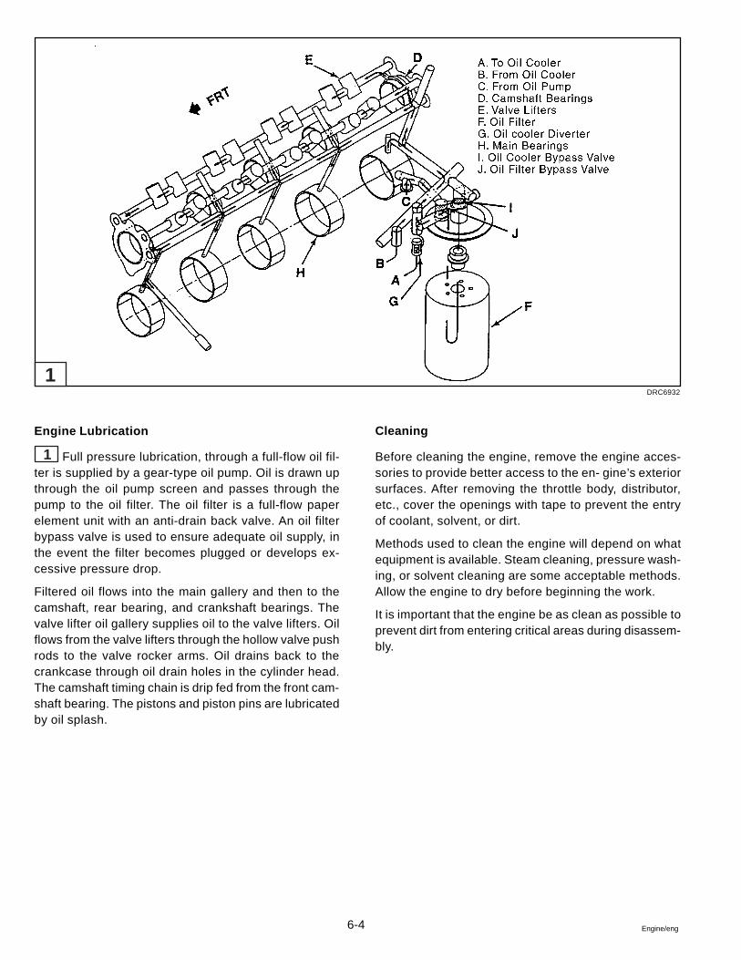
6-4 Engine/eng
Engine Lubrication
1 Full pressure lubrication, through a full-flow oil fil-ter is supplied by a gear-type oil pump. Oil is drawn upthrough the oil pump screen and passes through thepump to the oil filter. The oil filter is a full-flow paperelement unit with an anti-drain back valve. An oil filterbypass valve is used to ensure adequate oil supply, inthe event the filter becomes plugged or develops ex-cessive pressure drop.
Filtered oil flows into the main gallery and then to thecamshaft, rear bearing, and crankshaft bearings. Thevalve lifter oil gallery supplies oil to the valve lifters. Oilflows from the valve lifters through the hollow valve pushrods to the valve rocker arms. Oil drains back to thecrankcase through oil drain holes in the cylinder head.The camshaft timing chain is drip fed from the front cam-shaft bearing. The pistons and piston pins are lubricatedby oil splash.
Cleaning
Before cleaning the engine, remove the engine acces-sories to provide better access to the en- gine’s exteriorsurfaces. After removing the throttle body, distributor,etc., cover the openings with tape to prevent the entryof coolant, solvent, or dirt.
Methods used to clean the engine will depend on whatequipment is available. Steam cleaning, pressure wash-ing, or solvent cleaning are some acceptable methods.Allow the engine to dry before beginning the work.
It is important that the engine be as clean as possible toprevent dirt from entering critical areas during disassem-bly.
DRC6932
1
6-5Engine/eng
Tools and Shop Equipment
A clean, well lit work area should be available. Other necessary equip-ment includes: a suitable parts cleaning tank, compressed air supply,trays to keep parts and fasteners organized, and an adequate set ofhand tools.
An approved engine repair stand will help prevent personal injury or dam-age to engine components.
Special tools are illustrated throughout this section and listed at its end.These tools (or their equivalents) are specially designed to quickly andsafely accomplish the operations for which they are intended. The useof these tools will also minimize possible damage to engine components.
Some precision measuring tools are required for inspection of certaincritical components. Torque wrenches will be necessary to correctlytighten various fasteners. Those fasteners will be called out within thissection.
Accessories
This manual assumes that the engine accessories have been removed.These accessories may include one or more of the following:
• Power Steering Pump
• Alternator
• Distributor
• Water Supply Pump
• Accessory Brackets and Electrical Wiring
• Starter Motor
It is beyond the scope of this section to detail the many different acces-sory installations. Refer to the proper Service Manual for this informa-tion. Diagrams of vacuum hose routing, wiring harness routing, acces-sory drive belt layout, etc., should be made before removing these com-ponents.
Draining The Engine
Follow the procedures in Section 1, General Information of this manualto drain crankcase engine oil and the cooling system.
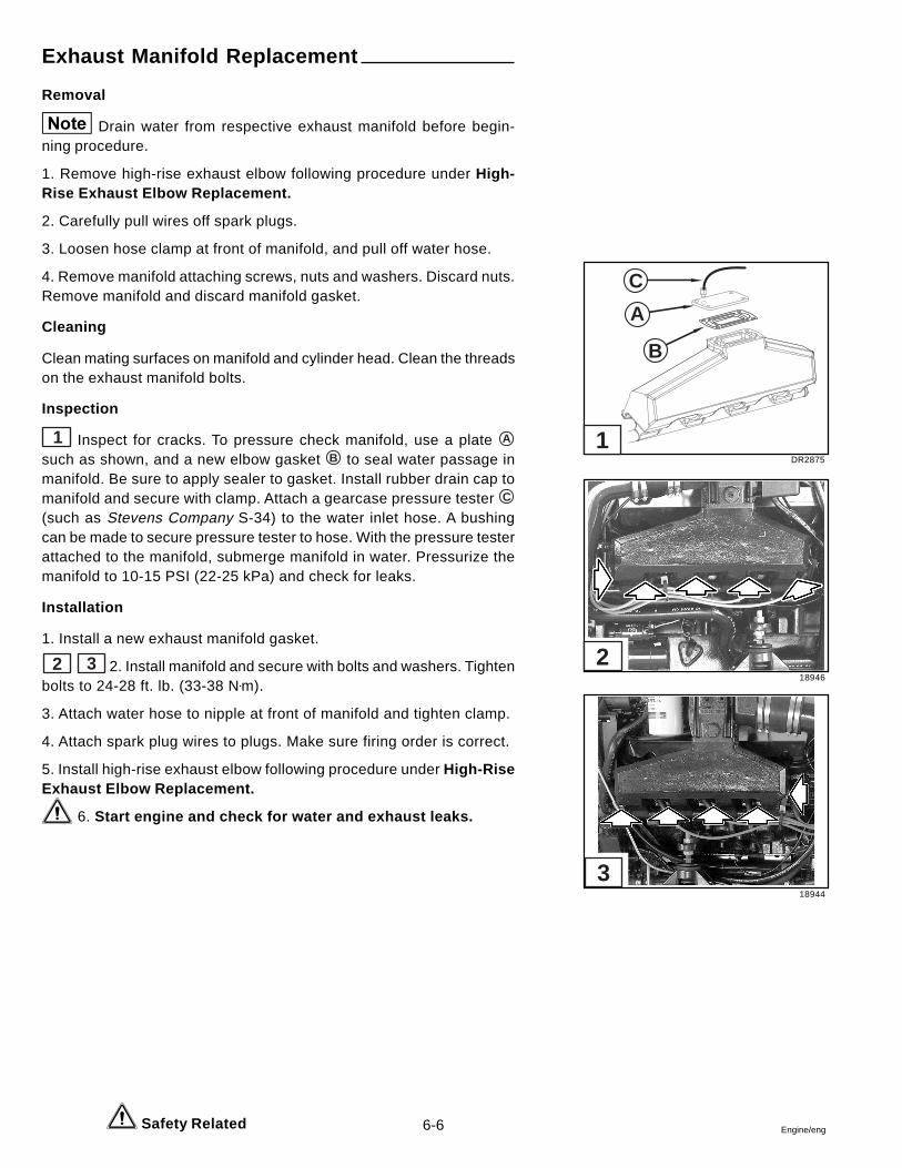
6-6 Engine/eng
Exhaust Manifold Replacement
Removal
Drain water from respective exhaust manifold before begin-ning procedure.
1. Remove high-rise exhaust elbow following procedure under High-Rise Exhaust Elbow Replacement.
2. Carefully pull wires off spark plugs.
3. Loosen hose clamp at front of manifold, and pull off water hose.
4. Remove manifold attaching screws, nuts and washers. Discard nuts.Remove manifold and discard manifold gasket.
Cleaning
Clean mating surfaces on manifold and cylinder head. Clean the threadson the exhaust manifold bolts.
Inspection
1 Inspect for cracks. To pressure check manifold, use a plate A
such as shown, and a new elbow gasket B to seal water passage inmanifold. Be sure to apply sealer to gasket. Install rubber drain cap tomanifold and secure with clamp. Attach a gearcase pressure tester C
(such as Stevens Company S-34) to the water inlet hose. A bushingcan be made to secure pressure tester to hose. With the pressure testerattached to the manifold, submerge manifold in water. Pressurize themanifold to 10-15 PSI (22-25 kPa) and check for leaks.
Installation
1. Install a new exhaust manifold gasket.
2 3 2. Install manifold and secure with bolts and washers. Tightenbolts to 24-28 ft. lb. (33-38 N•m).
3. Attach water hose to nipple at front of manifold and tighten clamp.
4. Attach spark plug wires to plugs. Make sure firing order is correct.
5. Install high-rise exhaust elbow following procedure under High-RiseExhaust Elbow Replacement.
6. Start engine and check for water and exhaust leaks.
Safety Related
DR2875
18946
18944
C
A
B
1
2
3
6-7Engine/eng
Crankshaft Balancer Removal
Tools Required: J 23523-F Crankshaft Balancer Remover/Installer
Remove or Disconnect:
1. Crankshaft balancer retaining bolt and washer.
4 2. Crankshaft balancer using Special Tool P/N J 23523-F Crank-shaft Balancer Remover/Installer.
Intake Manifold Removal
Remove or Disconnect:
5 1. Upper intake manifold bolts.
2. Upper intake manifold and gaskets. Discard the gaskets.
6 3. Lower intake manifold bolts.
Do not attempt to loosen the manifold by prying underthe gasket surface with any tool. The lower intake manifold gaskets arereusable.
4. Lower intake manifold by pulling up on the manifold.
5. Lower intake manifold gaskets and seals.
Valve Rocker Arm Cover Removal
Remove or Disconnect:
7 1. Valve rocker arm cover bolts.
2. Valve rocker arm cover and gasket. Discard the gasket.
Important
DRC6913
DRC6891
DRC6893
DRC6895
4
5
6
7
6-8 Engine/eng
Valve Rocker Arm and Push Rod Removal
Tools Required: J 3049-A Valve Lifter Removal (Plier Type)
J 9290-01 Valve Lifter Removal (Slide Hammer Type)
Every effort shou Id be made to ensure that themating parts are installed in their original locations during assembly.
Remove or Disconnect:
1 1. Valve rocker arm bolts, balls, rocker arms and push rod guides.
2 2. Valve push rods. Note: The exhaust valve push rods are longerthan the intake valve push rods.
3 3. Splash shield.
4 4. Valve lifter guide retainer bolts and retainer.
5 5. Lifter guides.
6. Valve lifters
a. Use a magnet in order to remove the valve lifters one at atime.
b. Tag the valve lifters in a way to ensure they can be returnedto the valve lifter bore from which they were removed.
c. Some valve lifters may be stuck in their bore due to gum orvarnish deposits. These valve lifters can be removed by us-ing either J 3049-A Valve Lifter Removal (Plier Type), or J9290-01 Valve Lifter Removal (Slide Hammer Type).
Important
DRC6896
DRC6897
DRC6914
DRC6915
DRC6916
1
2
3
4
5
6-9Engine/eng
Cylinder Head Removal
Remove or Disconnect:
6 1. Cylinder head bolts.
2. Cylinder Head. Note: Handle the cylinder heads carefully to preventdamage to the gasket sealing surfaces.
3. Cylinder head gasket. Discard the gasket.
Oil Pan Removal
Remove or Disconnect:
7 1. Oil pan bolts.
2. Oil pan.
3. Oil pan gasket. Discard the gasket.
Oil Pump Removal
Remove or Disconnect:
8 1. Bolts that attach the oil pump to the rear crankshaft bearing cap.
2. Oil pump, the retainer, and the driveshaft from the rear crankshaftbearing cap.
Engine Front Cover Removal
Remove or Disconnect:
9 1. Engine front cover bolts.
2. Engine front cover and gasket. Note: The engine front cover gasket isreusable.
DRC6907
DRC6909
DRC6910
DRC6901
6
7
8
9
6-10 Engine/eng
Timing Chain and Sprockets Removal
Tools Required: J 28509-A Crankshaft Sprocket Remover
Measure:The camshaft timing chain free play. If the chain can bemoved back and forth in excess of 0.625 in. (16 mm), make a notethat the camshaft timing chain and sprockets must be replacedduring assembly.
Remove or Disconnect:
1 1. Camshaft sprocket bolts.
2. Camshaft sprocket and camshaft timing chain.
2 3. Crankshaft sprocket using J 28509-A Crankshaft Sprocket Re-mover.
4. Crankshaft key, if necessary.
Camshaft Removal
3 Remove or Disconnect:
1. Camshaft retainer bolts and camshaft retainer.
2. Install three 5/16 - 18 x 4 in. bolts in the camshaft front bolt holes.
3. Carefully rotate and pull the camshaft out of the engine block.
DRC6903
DRC6904
DRC6906
1
2
3
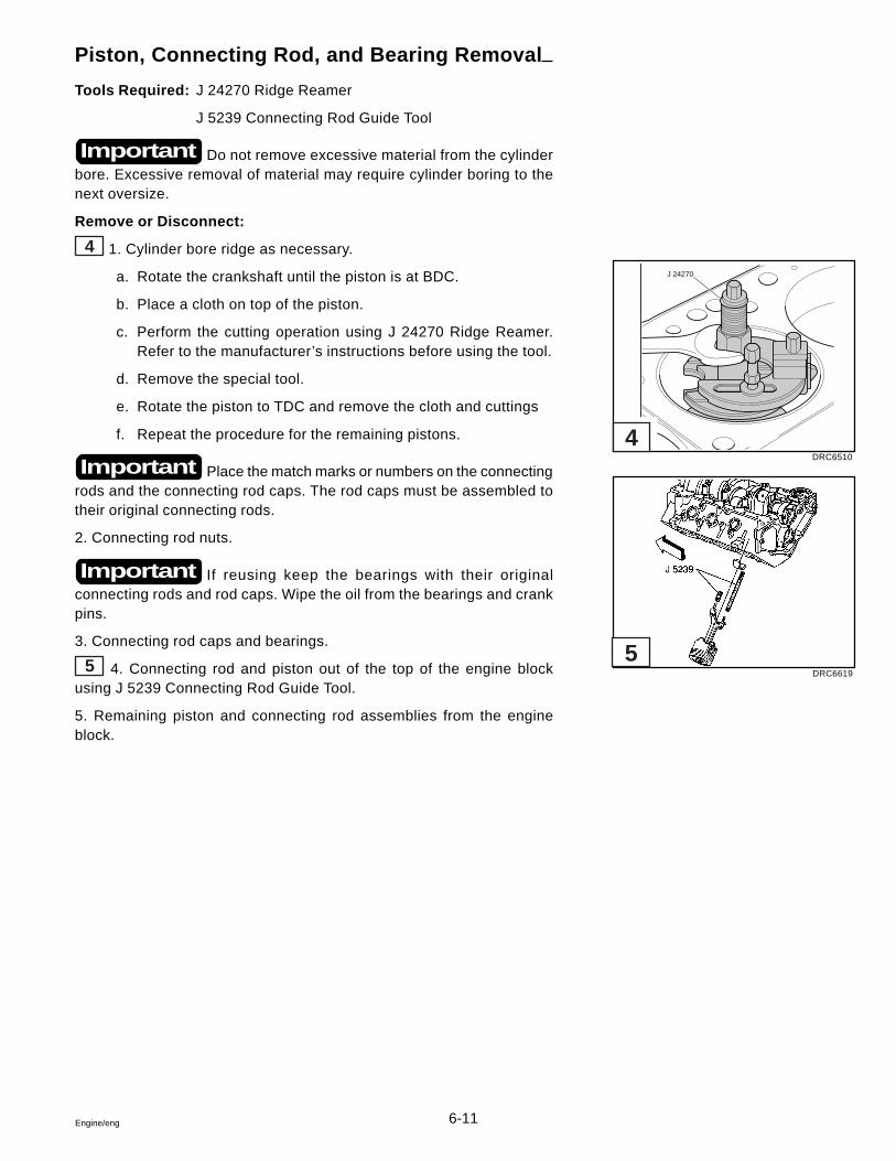
6-11Engine/eng
Piston, Connecting Rod, and Bearing Removal
Tools Required: J 24270 Ridge Reamer
J 5239 Connecting Rod Guide Tool
Do not remove excessive material from the cylinderbore. Excessive removal of material may require cylinder boring to thenext oversize.
Remove or Disconnect:
4 1. Cylinder bore ridge as necessary.
a. Rotate the crankshaft until the piston is at BDC.
b. Place a cloth on top of the piston.
c. Perform the cutting operation using J 24270 Ridge Reamer.Refer to the manufacturer’s instructions before using the tool.
d. Remove the special tool.
e. Rotate the piston to TDC and remove the cloth and cuttings
f. Repeat the procedure for the remaining pistons.
Place the match marks or numbers on the connectingrods and the connecting rod caps. The rod caps must be assembled totheir original connecting rods.
2. Connecting rod nuts.
If reusing keep the bearings with their originalconnecting rods and rod caps. Wipe the oil from the bearings and crankpins.
3. Connecting rod caps and bearings.
5 4. Connecting rod and piston out of the top of the engine blockusing J 5239 Connecting Rod Guide Tool.
5. Remaining piston and connecting rod assemblies from the engineblock.
Important
Important
Important
DRC6510
DRC6619
J 24270
4
5
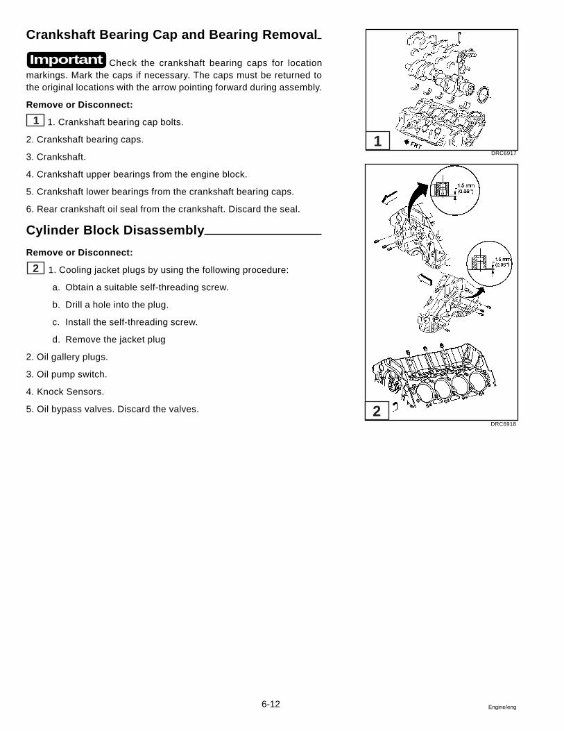
6-12 Engine/eng
Crankshaft Bearing Cap and Bearing Removal
Check the crankshaft bearing caps for locationmarkings. Mark the caps if necessary. The caps must be returned tothe original locations with the arrow pointing forward during assembly.
Remove or Disconnect:
1 1. Crankshaft bearing cap bolts.
2. Crankshaft bearing caps.
3. Crankshaft.
4. Crankshaft upper bearings from the engine block.
5. Crankshaft lower bearings from the crankshaft bearing caps.
6. Rear crankshaft oil seal from the crankshaft. Discard the seal.
Cylinder Block Disassembly
Remove or Disconnect:
2 1. Cooling jacket plugs by using the following procedure:
a. Obtain a suitable self-threading screw.
b. Drill a hole into the plug.
c. Install the self-threading screw.
d. Remove the jacket plug
2. Oil gallery plugs.
3. Oil pump switch.
4. Knock Sensors.
5. Oil bypass valves. Discard the valves.
Important
DRC6917
DRC6918
1
2
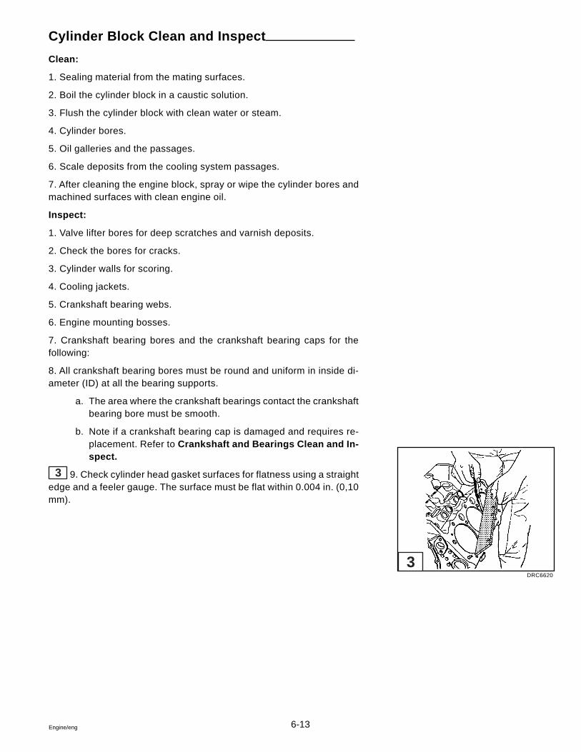
6-13Engine/eng
Cylinder Block Clean and Inspect
Clean:
1. Sealing material from the mating surfaces.
2. Boil the cylinder block in a caustic solution.
3. Flush the cylinder block with clean water or steam.
4. Cylinder bores.
5. Oil galleries and the passages.
6. Scale deposits from the cooling system passages.
7. After cleaning the engine block, spray or wipe the cylinder bores andmachined surfaces with clean engine oil.
Inspect:
1. Valve lifter bores for deep scratches and varnish deposits.
2. Check the bores for cracks.
3. Cylinder walls for scoring.
4. Cooling jackets.
5. Crankshaft bearing webs.
6. Engine mounting bosses.
7. Crankshaft bearing bores and the crankshaft bearing caps for thefollowing:
8. All crankshaft bearing bores must be round and uniform in inside di-ameter (ID) at all the bearing supports.
a. The area where the crankshaft bearings contact the crankshaftbearing bore must be smooth.
b. Note if a crankshaft bearing cap is damaged and requires re-placement. Refer to Crankshaft and Bearings Clean and In-spect.
3 9. Check cylinder head gasket surfaces for flatness using a straightedge and a feeler gauge. The surface must be flat within 0.004 in. (0,10mm).
DRC6620
3
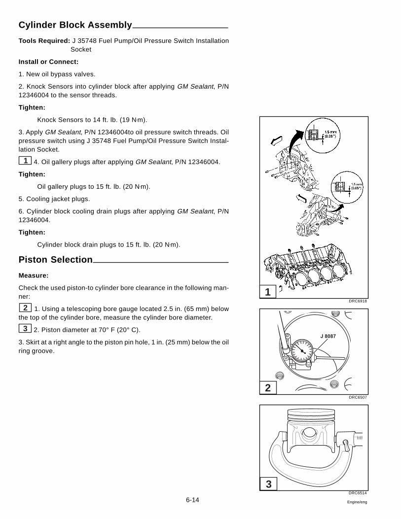
6-14 Engine/eng
Cylinder Block Assembly
Tools Required: J 35748 Fuel Pump/Oil Pressure Switch InstallationSocket
Install or Connect:
1. New oil bypass valves.
2. Knock Sensors into cylinder block after applying GM Sealant, P/N12346004 to the sensor threads.
Tighten:
Knock Sensors to 14 ft. lb. (19 N•m).
3. Apply GM Sealant, P/N 12346004to oil pressure switch threads. Oilpressure switch using J 35748 Fuel Pump/Oil Pressure Switch Instal-lation Socket.
1 4. Oil gallery plugs after applying GM Sealant, P/N 12346004.
Tighten:
Oil gallery plugs to 15 ft. lb. (20 N•m).
5. Cooling jacket plugs.
6. Cylinder block cooling drain plugs after applying GM Sealant, P/N12346004.
Tighten:
Cylinder block drain plugs to 15 ft. lb. (20 N•m).
Piston Selection
Measure:
Check the used piston-to cylinder bore clearance in the following man-ner:
2 1. Using a telescoping bore gauge located 2.5 in. (65 mm) belowthe top of the cylinder bore, measure the cylinder bore diameter.
3 2. Piston diameter at 70° F (20° C).
3. Skirt at a right angle to the piston pin hole, 1 in. (25 mm) below the oilring groove.
DRC6918
DRC6507
DRC6514
J 8087
1
2
3
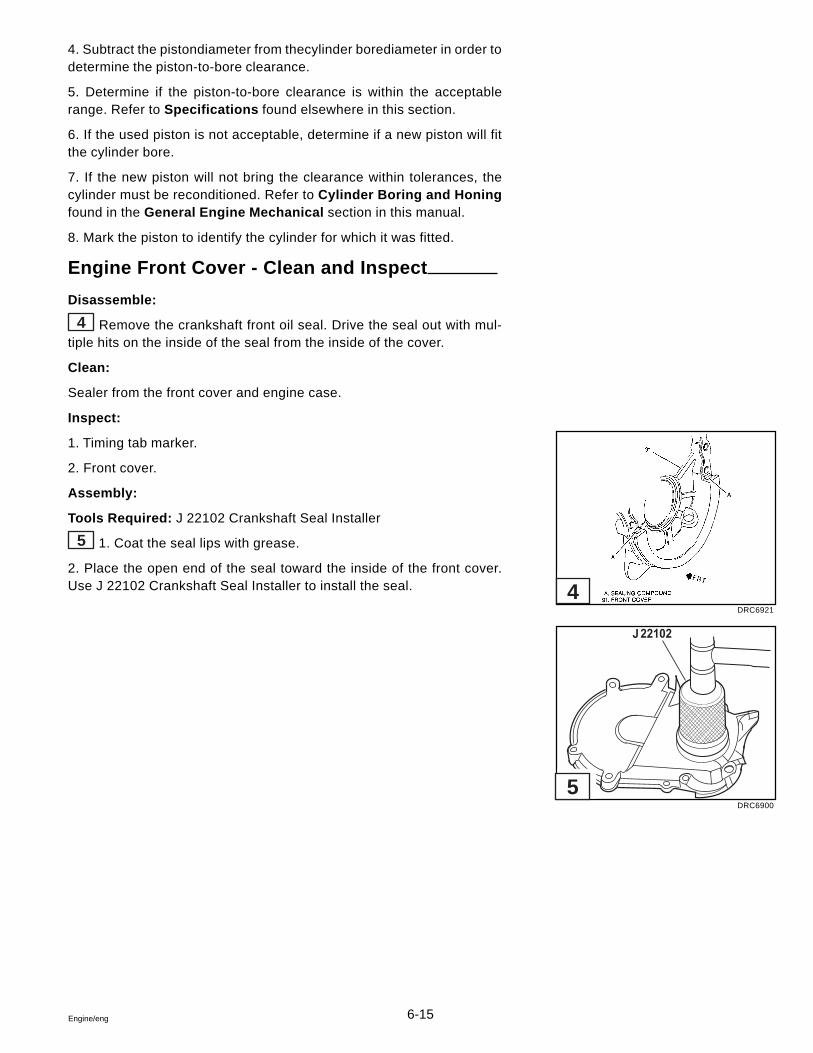
6-15Engine/eng
4. Subtract the pistondiameter from thecylinder borediameter in order todetermine the piston-to-bore clearance.
5. Determine if the piston-to-bore clearance is within the acceptablerange. Refer to Specifications found elsewhere in this section.
6. If the used piston is not acceptable, determine if a new piston will fitthe cylinder bore.
7. If the new piston will not bring the clearance within tolerances, thecylinder must be reconditioned. Refer to Cylinder Boring and Honingfound in the General Engine Mechanical section in this manual.
8. Mark the piston to identify the cylinder for which it was fitted.
Engine Front Cover - Clean and Inspect
Disassemble:
4 Remove the crankshaft front oil seal. Drive the seal out with mul-tiple hits on the inside of the seal from the inside of the cover.
Clean:
Sealer from the front cover and engine case.
Inspect:
1. Timing tab marker.
2. Front cover.
Assembly:
Tools Required: J 22102 Crankshaft Seal Installer
5 1. Coat the seal lips with grease.
2. Place the open end of the seal toward the inside of the front cover.Use J 22102 Crankshaft Seal Installer to install the seal.
DRC6921
DRC6900
4
5
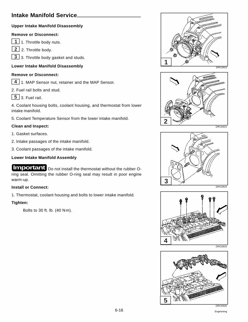
6-16 Engine/eng
Intake Manifold Service
Upper Intake Manifold Disassembly
Remove or Disconnect:
1 1. Throttle body nuts.
2 2. Throttle body.
3 3. Throttle body gasket and studs.
Lower Intake Manifold Disassembly
Remove or Disconnect:
4 1. MAP Sensor nut, retainer and the MAP Sensor.
2. Fuel rail bolts and stud.
5 3. Fuel rail.
4. Coolant housing bolts, coolant housing, and thermostat from lowerintake manifold.
5. Coolant Temperature Sensor from the lower intake manifold.
Clean and Inspect:
1. Gasket surfaces.
2. Intake passages of the intake manifold.
3. Coolant passages of the intake manifold.
Lower Intake Manifold Assembly
Do not install the thermostat without the rubber O-ring seal. Omitting the rubber O-ring seal may result in poor enginewarm-up.
Install or Connect:
1. Thermostat, coolant housing and bolts to lower intake manifold.
Tighten:
Bolts to 30 ft. lb. (40 N•m).
Important
DRC6922
DRC6923
DRC6924
DRC6925
DRC6926
5
4
3
2
1
6-17Engine/eng
2. Coolant Temperature sensor to lower intake manifold after applyingGM Sealant, P/N 12346004.
Tighten:
Sensor to 15 ft. lb. (20 N•m).
Lubricate the injector O-ring seals with clean engineoil and install on the spray tip end of each injector.
5 3. Fuel rail assembly in the intake manifold. Tilt the rail assembly toinstall the injectors.
4 4. Fuel rail attaching bolts and stud.
Tighten:
Bolts to 89 in. lb. (10 N•m)
Stud to 18 ft. lb. (25 N•m).
5. MAP Sensor, retainer, and nut to the lower intake manifold.
Tighten:
Nut to 18 ft. lb. (25 N•m).
Upper Intake Manifold Assembly
Install or Connect:
3 1. Throttle body studs.
Tighten:
Studs to 106 in. lb. (12 N•m).
2. Throttle body gasket.
2 3. Throttle body.
1 4. Throttle body nuts.
Tighten:
Nuts to 89 in. lb. (10 N•m).
Important
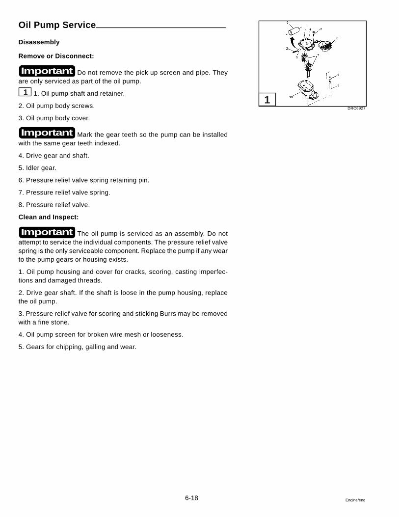
6-18 Engine/eng
Oil Pump Service
Disassembly
Remove or Disconnect:
Do not remove the pick up screen and pipe. Theyare only serviced as part of the oil pump.
1 1. Oil pump shaft and retainer.
2. Oil pump body screws.
3. Oil pump body cover.
Mark the gear teeth so the pump can be installedwith the same gear teeth indexed.
4. Drive gear and shaft.
5. Idler gear.
6. Pressure relief valve spring retaining pin.
7. Pressure relief valve spring.
8. Pressure relief valve.
Clean and Inspect:
The oil pump is serviced as an assembly. Do notattempt to service the individual components. The pressure relief valvespring is the only serviceable component. Replace the pump if any wearto the pump gears or housing exists.
1. Oil pump housing and cover for cracks, scoring, casting imperfec-tions and damaged threads.
2. Drive gear shaft. If the shaft is loose in the pump housing, replacethe oil pump.
3. Pressure relief valve for scoring and sticking Burrs may be removedwith a fine stone.
4. Oil pump screen for broken wire mesh or looseness.
5. Gears for chipping, galling and wear.
Important
Important
Important
DRC6927
1
6-19Engine/eng
Assembly
Install or Connect:
1. Pressure relief valve.
2. Pressure relief valve spring.
3. Pressure relief valve spring retaining pin.
4. Drive gear and shaft.
5. Idler gear.
6. Oil pump body cover.
7. Oil pump body screws.
Tighten:
Oil pump body screws to 106 in. lb. (12 N•m).
8. Oil pump driveshaft and retainer. Turn the driveshaft by hand to checkfor smooth operation.
Valve Train Components
Clean:
1. All parts in solvent.
2. Blow dry the parts with compressed air.
Inspect:
1. Valve rocker arms and balls atthe mating surfaces. These parts shouldbe smooth and free from scoring or other damage.
2. Valve rocker arm areas that Contact the valve stems and the socketsthat contact the push rods. These areas should be smooth and free ofdamage and wear.
3. Valve rocker are bolts for signs of cracking at the bolt shoulder. Re-place as necessary.
4. Valve push rods for bending. Roll the push rod on a flat surface inorder to determine if it is bent. Replace as necessary.
5. Ends of the valve push rods for scoring or roughness.
6. Valve push rod oil passage for restrictions.
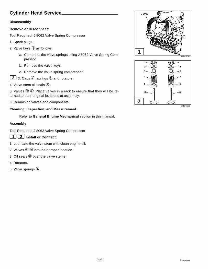
6-20 Engine/eng
Cylinder Head Service
Disassembly
Remove or Disconnect:
Tool Required: J 8062 Valve Spring Compressor
1. Spark plugs.
2. Valve keys 1 as follows:
a. Compress the valve springs using J 8062 Valve Spring Com-pressor
b. Remove the valve keys,
c. Remove the valve spring compressor.
2 3. Caps 2 , springs 4 and rotators.
4. Valve stem oil seals 3 .
5. Valves 5 6 . Place valves in a rack to ensure that they will be re-turned to their original locations at assembly.
6. Remaining valves and components.
Cleaning, Inspection, and Measurement
Refer to General Engine Mechanical section in this manual.
Assembly
Tool Required: J 8062 Valve Spring Compressor
1 2 Install or Connect:
1. Lubricate the valve stem with clean engine oil.
2. Valves 5 6 into their proper location.
3. Oil seals 3 over the valve stems.
4. Rotators.
5. Valve springs 4 .
DRC6663
DRC6595
1
2
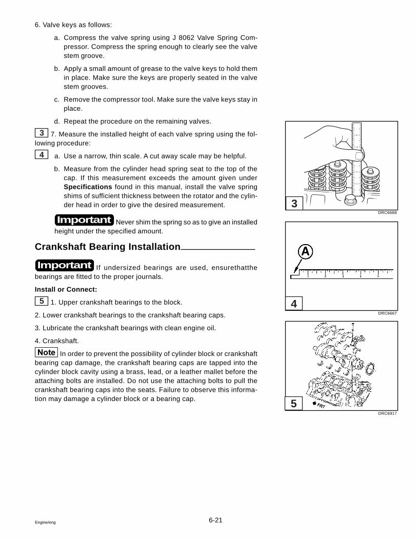
6-21Engine/eng
12
54
6. Valve keys as follows:
a. Compress the valve spring using J 8062 Valve Spring Com-pressor. Compress the spring enough to clearly see the valvestem groove.
b. Apply a small amount of grease to the valve keys to hold themin place. Make sure the keys are properly seated in the valvestem grooves.
c. Remove the compressor tool. Make sure the valve keys stay inplace.
d. Repeat the procedure on the remaining valves.
3 7. Measure the installed height of each valve spring using the fol-lowing procedure:
4 a. Use a narrow, thin scale. A cut away scale may be helpful.
b. Measure from the cylinder head spring seat to the top of thecap. If this measurement exceeds the amount given underSpecifications found in this manual, install the valve springshims of sufficient thickness between the rotator and the cylin-der head in order to give the desired measurement.
Never shim the spring so as to give an installedheight under the specified amount.
Crankshaft Bearing Installation
If undersized bearings are used, ensurethatthebearings are fitted to the proper journals.
Install or Connect:
5 1. Upper crankshaft bearings to the block.
2. Lower crankshaft bearings to the crankshaft bearing caps.
3. Lubricate the crankshaft bearings with clean engine oil.
4. Crankshaft.
In order to prevent the possibility of cylinder block or crankshaftbearing cap damage, the crankshaft bearing caps are tapped into thecylinder block cavity using a brass, lead, or a leather mallet before theattaching bolts are installed. Do not use the attaching bolts to pull thecrankshaft bearing caps into the seats. Failure to observe this informa-tion may damage a cylinder block or a bearing cap.
Important
Important
DRC6668
DRC6667
DRC6917
3
4
5
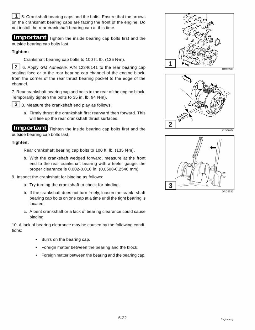
6-22 Engine/eng
1 5. Crankshaft bearing caps and the bolts. Ensure that the arrowson the crankshaft bearing caps are facing the front of the engine. Donot install the rear crankshaft bearing cap at this time.
Tighten the inside bearing cap bolts first and theoutside bearing cap bolts last.
Tighten:
Crankshaft bearing cap bolts to 100 ft. lb. (135 N•m).
2 6. Apply GM Adhesive, P/N 12346141 to the rear bearing capsealing face or to the rear bearing cap channel of the engine block,from the corner of the rear thrust bearing pocket to the edge of thechannel.
7. Rear crankshaft bearing cap and bolts to the rear of the engine block.Temporarily tighten the bolts to 35 in. lb. 94 N•m).
3 8. Measure the crankshaft end play as follows:
a. Firmly thrust the crankshaft first rearward then forward. Thiswill line up the rear crankshaft thrust surfaces.
Tighten the inside bearing cap bolts first and theoutside bearing cap bolts last.
Tighten:
Rear crankshaft bearing cap bolts to 100 ft. lb. (135 N•m).
b. With the crankshaft wedged forward, measure at the frontend to the rear crankshaft bearing with a feeler gauge. theproper clearance is 0.002-0.010 in. (0,0508-0,2540 mm).
9. Inspect the crankshaft for binding as follows:
a. Try turning the crankshaft to check for binding.
b. If the crankshaft does not turn freely, loosen the crank- shaftbearing cap bolts on one cap at a time until the tight bearing islocated.
c. A bent crankshaft or a lack of bearing clearance could causebinding.
10. A lack of bearing clearance may be caused by the following condi-tions:
• Burrs on the bearing cap.
• Foreign matter between the bearing and the block.
• Foreign matter between the bearing and the bearing cap.
Important
Important
DRC6917
DRC6929
DRC6530
1
2
3
6-23Engine/eng
Crankshaft Rear Oil Seal Installation
Tool Required: J 38841 Crankshaft Rear Oil Seal Installer
1. Make sure the crankshaft rear chamfer is free of grit, loose rust, andburrs. Correct as needed.
2. Lubricate the inner and outer diameter of the seal with engine oil.
4 3. Install the seal on J 38841 Crankshaft Rear Oil Seal Installer.
4. Position J 38841 Crankshaft Rear Oil Seal Installer against the crank-shaft. Thread the attaching screws into the tapped holes in the crank-shaft.
5. Tighten the screws securely with a screwdriver in order to ensure thatthe seal is installed squarely over the crankshaft.
6. Turn the handle until it bottoms.
7. Remove J 38841 Crankshaft Rear Oil Seal Installer.
Piston, Connecting Rod, and BearingInstallation
Tools Required: J 5239 Connecting Rod Guide Tool
J 8037 Piston Ring Compressor
In order to determine the correct replacement bearing size, the bearingclearance must be measured accurately. Either the micrometer or plas-tic gauge method may be used, however the micrometer method givesmore reliable results and is preferred. Refer to Crankshaft and Con-necting Rod Bearings, Cleaning and Inspection found in this manualfor either procedure.
Do not shim, scrape, or file bearing inserts. Do not touch thebearing surface of the insert with bare fingers. Skin oil and acids willetch the bearing surface.
Install or Connect:
1. Connecting rod bearings to the connecting rods and connecting rodcaps.
2. Lubricate the cylinder walls lightly with engine oil.
5 3. J 5239 Connecting Rod Guide Tool onto the connecting rod bolts.
6 4. Align the piston ring end gaps.
DRC6939
DRC6619
DRC6627
J 35621
FORWARD
A - POSITION OF THE GAP FOR THE SPACER OF THE OIL RINGB - POSITION OF THE GAP FOR THE OIL RINGC - POSITION OF THE GAP FOR THE LOWER COMPRESSION RINGD - POSITION OF THE GAP FOR THE UPPER COMPRESSION RING
B
B
C A D
4
5
6
6-24 Engine/eng
5. Lubricate the piston and the rings with engine oil.
1 6. J 8037 Piston Ring Compressor over the piston and rings as-sembly without disturbing the eng gap locations.
7. Compress the piston rings.
2 8. Ensure that the dimple faces the front of the block.
Each connecting rod and bearing cap should bemarked for proper location and orientation. Cylinder 1, 3, 5, and 7 arethe right bank and 2, 4, 6, and 8 are the left bank (when viewed fromthe front of the engine). The numbers on the connecting rod and bearingcap must be on the same side when installed in the cylinder bore. If aconnecting rod is ever transposed from one block or cylinder to another,new connecting rod bearings should be fitted and the connecting rodshould be numbered to corre- spond with the new cylinder number.
1 9. Piston and connecting rod into proper cylinder bore.
10. Use a hammer to lightly tap the piston down into the cylinder bore.
11. Guide the connecting rod into position on the crankpin, while tap-ping the piston into the bore.
12. Coat the connecting rod bearings with clean engine oil.
13. Coat the crankpin with clean engine oil.
14. Connecting rod cap with the bearing and connecting rod nuts.
Tighten:
Connecting rod nuts to 45 ft. lb. (61 N•m).
Camshaft Installation
Install or Connect
1. Camshaft as follows:
3 a. Install three 5/16 - 19 X 4 in. bolts into the camshaft front boltholes in order to handle the camshaft.
b. Use care to avoid damaging the camshaft bearings.
c. Remove the three bolts after the camshaft is installed.
Important
DRC6628
DRC6919
DRC6906
J 8037
1
2
3
6-25Engine/eng
2. Camshaft retainer and bolts.
Tighten:
Camshaft retainer bolts to 10 ft. lb. (14 N•m).
Timing Chain and Sprockets Installation
Tools Required: J 22102 Crankshaft Sprocket Installer
Install or Connect
1. Crankshaft key, as necessary.
Ensure that the sprocket alignment mark faces awayfrom the engine block. Ensure that the sprocket is fully seated againstthe crank shoulder.
4 2. Crankshaft sprocket using J 22102 Crankshaft Sprocket Installer.
Ensure the following conditions exist:
a. The camshaft and crankshaft timing marks are aligned.
b. The camshaft dowel pin and camshaft sprocket hole are prop-erly aligned.
c. The gears and timing chain mesh.
3. Camshaft timing chain to the camshaft sprocket.
5 4. Camshaft sprocket and the camshaft timing chain to the front ofthe camshaft.
Do not hammer the camshaft sprocket onto the camshaft. To doso may dislodge the rear camshaft plug and damage the camshaft.
5. Camshaft sprocket bolts. Use the bolts to draw the camshaft sprocketonto the camshaft.
Tighten:
Camshaft sprocket bolts to 25 ft. lb. (34 N•m).
Important
Important
DRC6905
DRC6902
4
5
6-26 Engine/eng
Engine Front Cover Installation
Install or Connect:
1 1. Lubricate the sealing surface of the crankcase front oil sealwith clean engine oil.
2. Apply GM Adhesive, P/N 12345739, or the equivalent in two placeswhere the front cover meets the oil pan rail.
2 3. Engine front cover.
4. Engine front cover screws.
Tighten:
Engine front cover screws to 106 in. lb. (12 N•m).
Oil Pump Installation
Install or Connect:
3 1. Oil pump driveshaft and retainer.
2. Oil pump.
3. Oil pump bolt.
Tighten:
Oil pump bolt to 65 ft. lb. (90 N•m).
Oil Pan Installation
Install the oil pan within 10 minutes of the adhesiveapplication.
Install or Connect:
4 1. Apply GM Adhesive, P/N 12345739, or the equivalent in fourplaces where the front and rear crankshaft bearing caps meet the en-gine block.
2. Oil pan gasket to the engine block.
Important
DRC6921
DRC6901
DRC6910
DRC6909
1
2
3
4
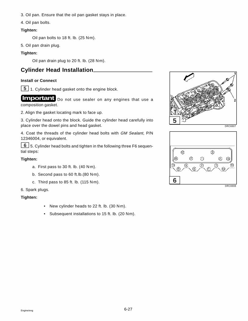
6-27Engine/eng
3. Oil pan. Ensure that the oil pan gasket stays in place.
4. Oil pan bolts.
Tighten:
Oil pan bolts to 18 ft. lb. (25 N•m).
5. Oil pan drain plug.
Tighten:
Oil pan drain plug to 20 ft. lb. (28 N•m).
Cylinder Head Installation
Install or Connect
5 1. Cylinder head gasket onto the engine block.
Do not use sealer on any engines that use acomposition gasket.
2. Align the gasket locating mark to face up.
3. Cylinder head onto the block. Guide the cylinder head carefully intoplace over the dowel pins and head gasket.
4. Coat the threads of the cylinder head bolts with GM Sealant, P/N12346004, or equivalent.
6 5. Cylinder head bolts and tighten in the following three F6 sequen-tial steps:
Tighten:
a. First pass to 30 ft. lb. (40 N•m).
b. Second pass to 60 ft.lb.(80 N•m).
c. Third pass to 85 ft. lb. (115 N•m).
6. Spark plugs.
Tighten:
• New cylinder heads to 22 ft. lb. (30 N•m).
• Subsequent installations to 15 ft. lb. (20 N•m).
Important
DRC6907
DRC6908
5
6
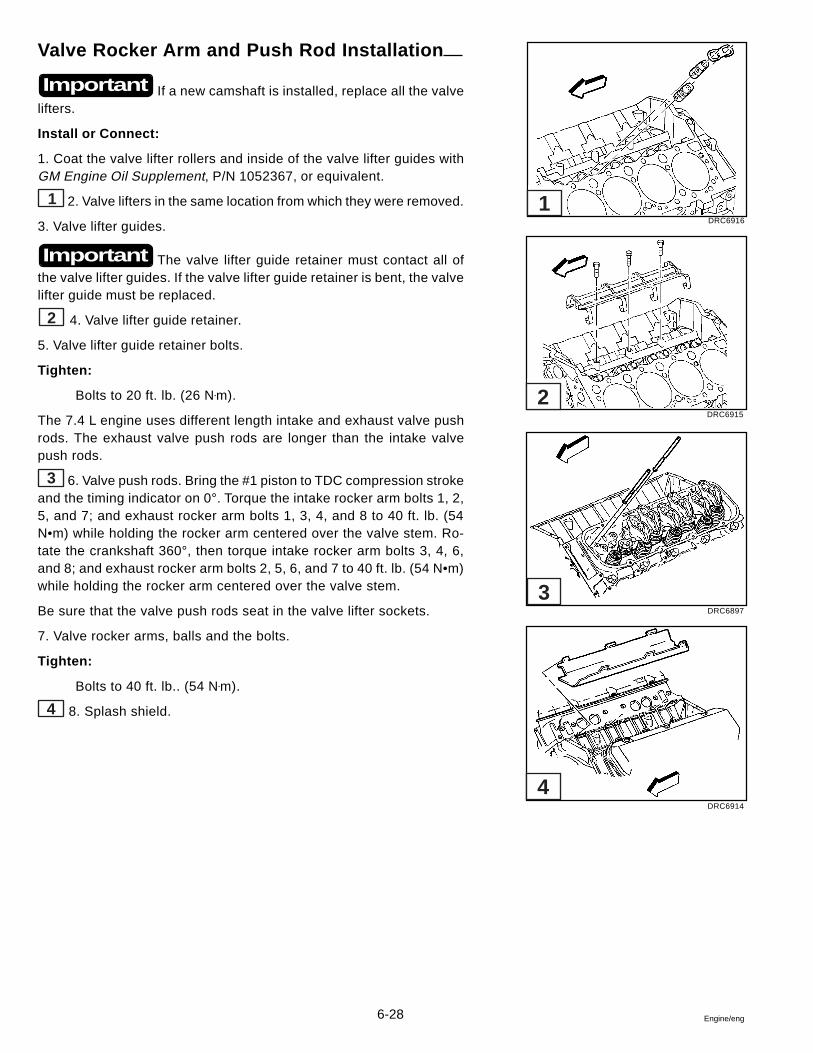
6-28 Engine/eng
Valve Rocker Arm and Push Rod Installation
If a new camshaft is installed, replace all the valvelifters.
Install or Connect:
1. Coat the valve lifter rollers and inside of the valve lifter guides withGM Engine Oil Supplement, P/N 1052367, or equivalent.
1 2. Valve lifters in the same location from which they were removed.
3. Valve lifter guides.
The valve lifter guide retainer must contact all ofthe valve lifter guides. If the valve lifter guide retainer is bent, the valvelifter guide must be replaced.
2 4. Valve lifter guide retainer.
5. Valve lifter guide retainer bolts.
Tighten:
Bolts to 20 ft. lb. (26 N•m).
The 7.4 L engine uses different length intake and exhaust valve pushrods. The exhaust valve push rods are longer than the intake valvepush rods.
3 6. Valve push rods. Bring the #1 piston to TDC compression strokeand the timing indicator on 0°. Torque the intake rocker arm bolts 1, 2,5, and 7; and exhaust rocker arm bolts 1, 3, 4, and 8 to 40 ft. lb. (54N•m) while holding the rocker arm centered over the valve stem. Ro-tate the crankshaft 360°, then torque intake rocker arm bolts 3, 4, 6,and 8; and exhaust rocker arm bolts 2, 5, 6, and 7 to 40 ft. lb. (54 N•m)while holding the rocker arm centered over the valve stem.
Be sure that the valve push rods seat in the valve lifter sockets.
7. Valve rocker arms, balls and the bolts.
Tighten:
Bolts to 40 ft. lb.. (54 N•m).
4 8. Splash shield.
Important
Important
DRC6916
DRC6915
DRC6897
DRC6914
1
2
3
4
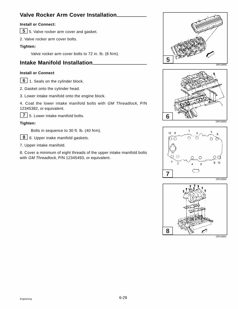
6-29Engine/eng
Valve Rocker Arm Cover Installation
Install or Connect:
5 5. Valve rocker arm cover and gasket.
2. Valve rocker arm cover bolts.
Tighten:
Valve rocker arm cover bolts to 72 in. lb. (8 N•m).
Intake Manifold Installation
Install or Connect
6 1. Seals on the cylinder block.
2. Gasket onto the cylinder head.
3. Lower intake manifold onto the engine block.
4. Coat the lower intake manifold bolts with GM Threadlock, P/N12345382, or equivalent.
7 5. Lower intake manifold bolts.
Tighten:
Bolts in sequence to 30 ft. lb. (40 N•m).
8 6. Upper inake manifold gaskets.
7. Upper intake manifold.
8. Cover a minimum of eight threads of the upper intake manifold boltswith GM Threadlock, P/N 12345493, or equivalent.
DRC6895
DRC6893
DRC6894
DRC6891
5
6
7
8
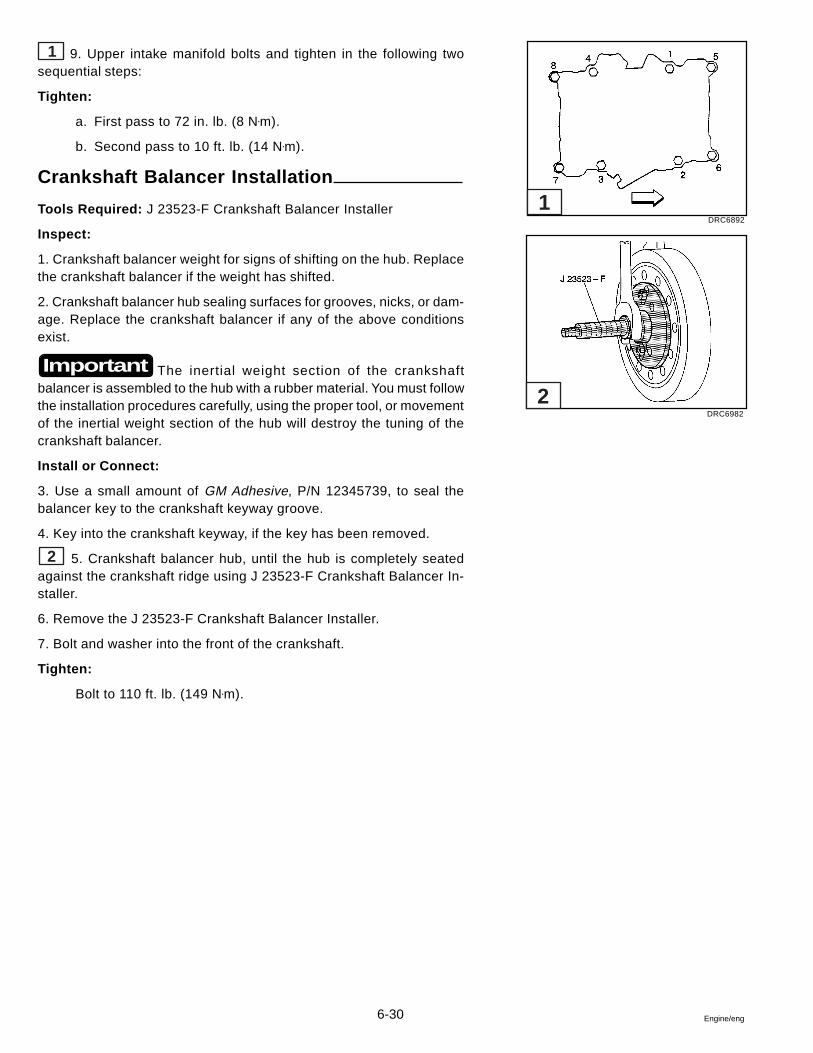
6-30 Engine/eng
1 9. Upper intake manifold bolts and tighten in the following twosequential steps:
Tighten:
a. First pass to 72 in. lb. (8 N•m).
b. Second pass to 10 ft. lb. (14 N•m).
Crankshaft Balancer Installation
Tools Required: J 23523-F Crankshaft Balancer Installer
Inspect:
1. Crankshaft balancer weight for signs of shifting on the hub. Replacethe crankshaft balancer if the weight has shifted.
2. Crankshaft balancer hub sealing surfaces for grooves, nicks, or dam-age. Replace the crankshaft balancer if any of the above conditionsexist.
The inertial weight section of the crankshaftbalancer is assembled to the hub with a rubber material. You must followthe installation procedures carefully, using the proper tool, or movementof the inertial weight section of the hub will destroy the tuning of thecrankshaft balancer.
Install or Connect:
3. Use a small amount of GM Adhesive, P/N 12345739, to seal thebalancer key to the crankshaft keyway groove.
4. Key into the crankshaft keyway, if the key has been removed.
2 5. Crankshaft balancer hub, until the hub is completely seatedagainst the crankshaft ridge using J 23523-F Crankshaft Balancer In-staller.
6. Remove the J 23523-F Crankshaft Balancer Installer.
7. Bolt and washer into the front of the crankshaft.
Tighten:
Bolt to 110 ft. lb. (149 N•m).
Important
DRC6892
DRC6982
1
2
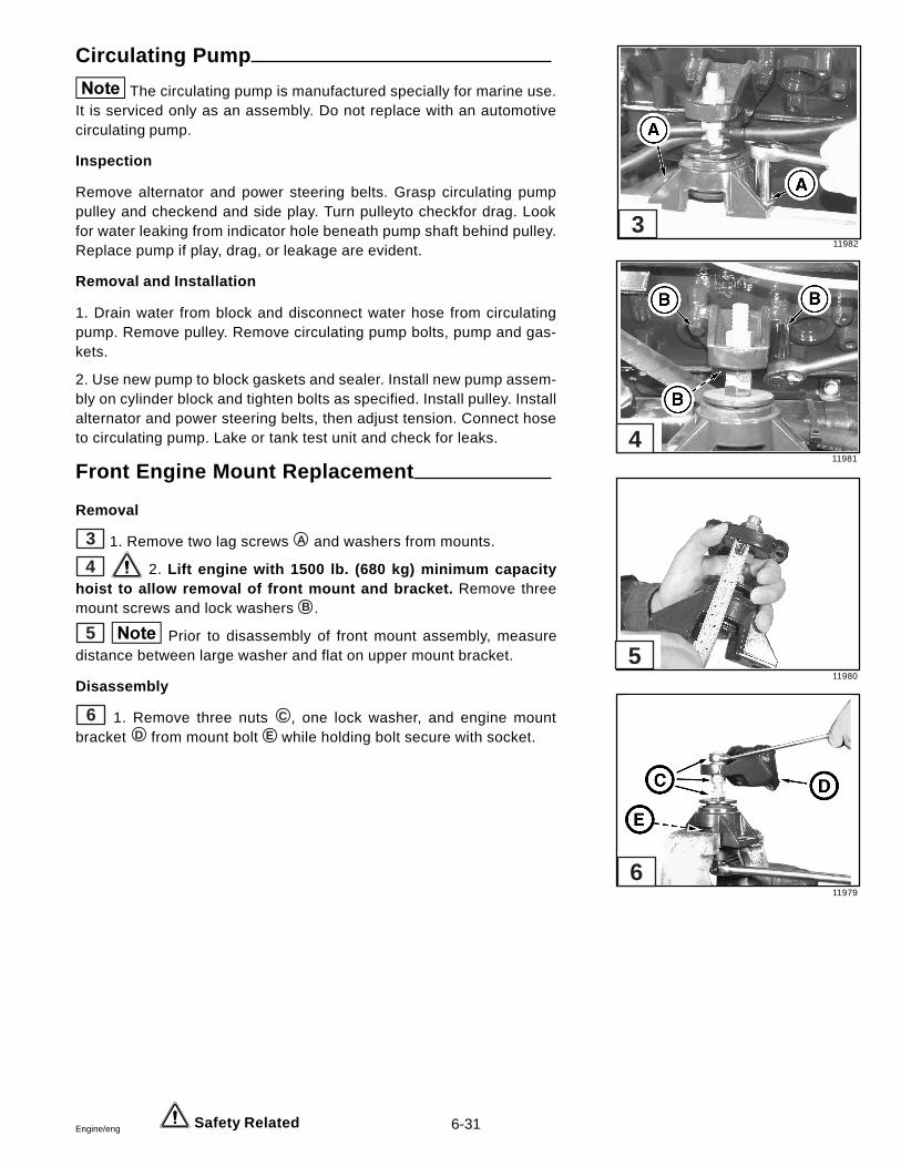
6-31Engine/eng
Circulating Pump
The circulating pump is manufactured specially for marine use.It is serviced only as an assembly. Do not replace with an automotivecirculating pump.
Inspection
Remove alternator and power steering belts. Grasp circulating pumppulley and checkend and side play. Turn pulleyto checkfor drag. Lookfor water leaking from indicator hole beneath pump shaft behind pulley.Replace pump if play, drag, or leakage are evident.
Removal and Installation
1. Drain water from block and disconnect water hose from circulatingpump. Remove pulley. Remove circulating pump bolts, pump and gas-kets.
2. Use new pump to block gaskets and sealer. Install new pump assem-bly on cylinder block and tighten bolts as specified. Install pulley. Installalternator and power steering belts, then adjust tension. Connect hoseto circulating pump. Lake or tank test unit and check for leaks.
Front Engine Mount Replacement
Removal
3 1. Remove two lag screws A and washers from mounts.
4 2. Lift engine with 1500 lb. (680 kg) minimum capacityhoist to allow removal of front mount and bracket. Remove threemount screws and lock washers B .
5 Prior to disassembly of front mount assembly, measuredistance between large washer and flat on upper mount bracket.
Disassembly
6 1. Remove three nuts C , one lock washer, and engine mountbracket D from mount bolt E while holding bolt secure with socket.
Safety Related
11982
11981
11980
11979
6
5
4
3
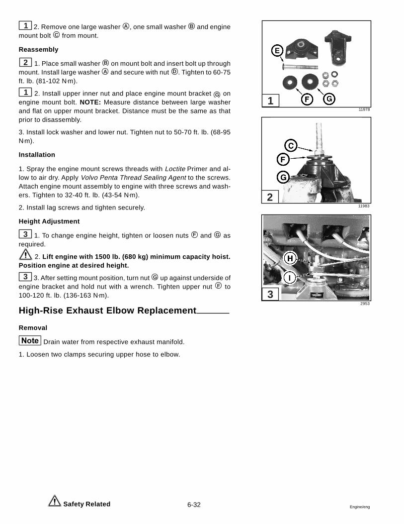
6-32 Engine/eng
1 2. Remove one large washer A , one small washer B and enginemount bolt C from mount.
Reassembly
2 1. Place small washer B on mount bolt and insert bolt up throughmount. Install large washer A and secure with nut D . Tighten to 60-75ft. lb. (81-102 N•m).
1 2. Install upper inner nut and place engine mount bracket G onengine mount bolt. NOTE: Measure distance between large washerand flat on upper mount bracket. Distance must be the same as thatprior to disassembly.
3. Install lock washer and lower nut. Tighten nut to 50-70 ft. lb. (68-95N•m).
Installation
1. Spray the engine mount screws threads with Loctite Primer and al-low to air dry. Apply Volvo Penta Thread Sealing Agent to the screws.Attach engine mount assembly to engine with three screws and wash-ers. Tighten to 32-40 ft. lb. (43-54 N•m).
2. Install lag screws and tighten securely.
Height Adjustment
3 1. To change engine height, tighten or loosen nuts F and G asrequired.
2. Lift engine with 1500 lb. (680 kg) minimum capacity hoist.Position engine at desired height.
3 3. After setting mount position, turn nut G up against underside ofengine bracket and hold nut with a wrench. Tighten upper nut F to100-120 ft. lb. (136-163 N•m).
High-Rise Exhaust Elbow Replacement
Removal
Drain water from respective exhaust manifold.
1. Loosen two clamps securing upper hose to elbow.
Safety Related
11978
11983
2953
1
2
3
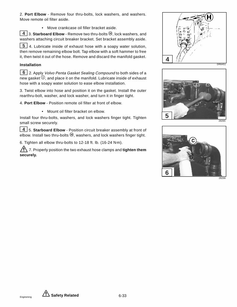
6-33Engine/eng
2. Port Elbow - Remove four thru-bolts, lock washers, and washers.Move remote oil filter aside.
• Move crankcase oil filler bracket aside.
4 3. Starboard Elbow - Remove two thru-bolts H , lock washers, andwashers attaching circuit breaker bracket. Set bracket assembly aside.
5 4. Lubricate inside of exhaust hose with a soapy water solution,then remove remaining elbow bolt. Tap elbow with a soft hammer to freeit, then twist it out of the hose. Remove and discard the manifold gasket.
Installation
6 2. Apply Volvo Penta Gasket Sealing Compound to both sides of anew gasket I , and place it on the manifold. Lubricate inside of exhausthose with a soapy water solution to ease elbow installation.
3. Twist elbow into hose and position it on the gasket. Install the outerrearthru-bolt, washer, and lock washer, and turn it in finger tight.
4. Port Elbow - Position remote oil filter at front of elbow.
• Mount oil filter bracket on elbow.
Install four thru-bolts, washers, and lock washers finger tight. Tightensmall screw securely.
4 5. Starboard Elbow - Position circuit breaker assembly at front ofelbow. Install two thru-bolts H , washers, and lock washers finger tight.
6. Tighten all elbow thru-bolts to 12-18 ft. lb. (16-24 N•m).
7. Properly position the two exhaust hose clamps and tighten themsecurely.
Safety Related
DR6451
28265
28266
6
5
4
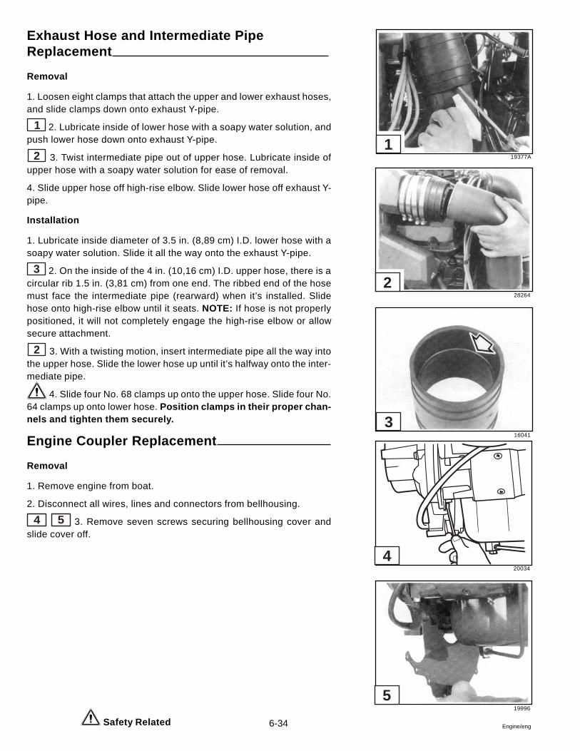
6-34 Engine/eng
20034
19996
4
5
Exhaust Hose and Intermediate PipeReplacement
Removal
1. Loosen eight clamps that attach the upper and lower exhaust hoses,and slide clamps down onto exhaust Y-pipe.
1 2. Lubricate inside of lower hose with a soapy water solution, andpush lower hose down onto exhaust Y-pipe.
2 3. Twist intermediate pipe out of upper hose. Lubricate inside ofupper hose with a soapy water solution for ease of removal.
4. Slide upper hose off high-rise elbow. Slide lower hose off exhaust Y-pipe.
Installation
1. Lubricate inside diameter of 3.5 in. (8,89 cm) I.D. lower hose with asoapy water solution. Slide it all the way onto the exhaust Y-pipe.
3 2. On the inside of the 4 in. (10,16 cm) I.D. upper hose, there is acircular rib 1.5 in. (3,81 cm) from one end. The ribbed end of the hosemust face the intermediate pipe (rearward) when it’s installed. Slidehose onto high-rise elbow until it seats. NOTE: If hose is not properlypositioned, it will not completely engage the high-rise elbow or allowsecure attachment.
2 3. With a twisting motion, insert intermediate pipe all the way intothe upper hose. Slide the lower hose up until it’s halfway onto the inter-mediate pipe.
4. Slide four No. 68 clamps up onto the upper hose. Slide four No.64 clamps up onto lower hose. Position clamps in their proper chan-nels and tighten them securely.
Engine Coupler Replacement
Removal
1. Remove engine from boat.
2. Disconnect all wires, lines and connectors from bellhousing.
4 5 3. Remove seven screws securing bellhousing cover andslide cover off.
Safety Related
19377A
28264
16041
3
2
1
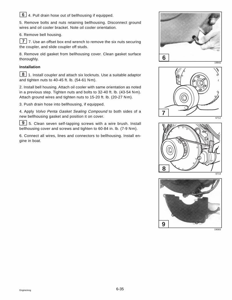
6-35Engine/eng
6 4. Pull drain hose out of bellhousing if equipped.
5. Remove bolts and nuts retaining bellhousing. Disconnect groundwires and oil cooler bracket. Note oil cooler orientation.
6. Remove bell housing.
7 7. Use an offset box end wrench to remove the six nuts securingthe coupler, and slide coupler off studs.
8. Remove old gasket from bellhousing cover. Clean gasket surfacethoroughly.
Installation
8 1. Install coupler and attach six locknuts. Use a suitable adaptorand tighten nuts to 40-45 ft. lb. (54-61 N•m).
2. Install bell housing. Attach oil cooler with same orientation as notedin a previous step. Tighten nuts and bolts to 32-40 ft. lb. (43-54 N•m).Attach ground wires and tighten nuts to 15-20 ft. lb. (20-27 N•m).
3. Push drain hose into bellhousing, if equipped.
4. Apply Volvo Penta Gasket Sealing Compound to both sides of anew bellhousing gasket and position it on cover.
9 5. Clean seven self-tapping screws with a wire brush. Installbellhousing cover and screws and tighten to 60-84 in. lb. (7-9 N•m).
6. Connect all wires, lines and connectors to bellhousing. Install en-gine in boat.
19842
6712
6714
19083
9
8
7
6
6-36 Engine/eng
Engine Specifications
General Information:
Type - No. of Cylinder ...................................................................................................................................90° - V-8Valve Arrangement ......................................................................................................................................... In headBore and Stroke ........................................................................................... 4.250 x 4.000 in. (107,95 x 101,6 mm)Piston Displacement ........................................................................................................ 7.4 Litre/454 Cubic InchesCylinder Numbers - Front to Rear
Starboard Bank......................................................................................................................................... 2-4-6-8Port Bank .................................................................................................................................................. 1-3-5-7
Firing Order ........................................................................................................................................ 1-8-4-3-6-5-7-2Compression Ratio ................................................................................................................................................ 8:1Water Temperature Control ..................................................................................................................... ThermostatThermostat Opens at .......................................................................................................................... 140° F. (60° C)Alternator Belt Adjustment .................................................................................... 1/4-1/2 in. give w/finger pressureFull Throttle Operation Range ....................................................................................................... 4200 - 4600 RPM
Pistons:
Production Clearance ............................................................................. 0.0018 - 0.0030 in. (0,0457 - 0,0762 mm)Service Limit .................................................................................... 0.0018 - 0.0048 in. (0,0457 - 0,219 mm) Max.
Piston Rings, Compression:
Production Groove ClearanceTop ......................................................................................................... 0.0012 - 0.0029 in. (0,031 - 0,074 mm)2nd ......................................................................................................... 0.0012 - 0.0029 in. (0,031 - 0,074 mm)
Service Groove Clearance (both) ............................................................ 0.0012 - 0.0039 in. (0,031 - 0,0991 mm)Gap
Top ............................................................................................................. 0.010 - 0.018 in. (0,254 - 0,475 mm)2nd ............................................................................................................. 0.016 - 0.024 in. (0,406 - 0,609 mm)
Service (both) .................................................................................................. 0.016 - 0.034 in. (0,406 - 0,863 mm)
Piston Rings, Oil:
Groove ClearanceProduction ................................................................................................ 0.005 - 0.0065 in. (0,127 - 0,165 mm)Service ................................................................................................... 0.0050 - 0.0075 in. (0,127 - 0,191 mm)
GapProduction .................................................................................................. 0.010 - 0.030 in. (0,254 - 0,762 mm)Service ...................................................................................................... 0.01 0 - 0.040 in. (0,254 - 1,016 mm)
6-37Engine/eng
Engine Specifications
Piston Pins:
Diameter .................................................................................................. 0.9895 - 0.9897 in. (25,132 - 25,137 mm)Clearance in Piston
Production..............................................................................................0.0002 - 0.0007 in. (0,005 - 0,017 mm)Service Limit ..........................................................................................0.0002 - 0.0001 in. (0,005 - 0,025 mm)
Rod Fit ..................................................................................... 0.0031 - 0.0021 in. (0,078 - 0,053 mm) lnterference
Connecting Rods:
Bearing ClearanceProduction............................................................................................ 0.001 1 - 0.0029 in. (0,028 - 0,074 mm)Service Limit ........................................................................................ 0.001 1 - 0.0039 in. (0,028 - 0,099 mm)
Side Clearance ............................................................................................0.0013 - 0.0230 in. (0,033 - 0,584 mm)
Crankshaft:
End Play ............................................................................................................ 0.005 - o.ol I in. (0,127 - 0,279 mm)Main Journal Diameter
No. 1, 2, 3, 4, 5 ................................................................................. 2.7482 - 2.7489 in. (69,804 - 69,822 mm)Taper
Production................................................................................................................ 0.0004 in. (0,010 mm) Max.Service Limit ............................................................................................................ 0.0010 in. (0,025 mm) Max.
Out -of-RoundProduction................................................................................................................ 0.0004 in. (0,010 mm) Max.Service Limit ............................................................................................................ 0.0010 in. (0,025 mm) Max.
Mai n Bearing Clearance, ProductionNo. 1 ......................................................................................................0.0017 - 0.0030 in. (0,043 - 0,076 mm)No. 2 ,3 , 4 ........................................................................................... 0.001 1 - 0.0024 in. (0,028 - 0,061 mm)No. 5 ......................................................................................................0.0025 - 0.0038 in. (0,063 - 0,096 mm)
Main Bearing Clearance, ServiceNo. 1, 2, 3, 4 ..........................................................................................0.0010 - 0.0030 in. (0,025 - 0,076 mm)No. 5 ......................................................................................................0.0025 - 0.0040 in. (0,063 - 0,101 mm)
Crankpin Diameter .................................................................................. 2.1990 - 2.1996 in. (55,854 - 55,869 mm)Taper
Production ....................................................................................................... 0.0005 in. (0,0127 mm) Max.Service Limit ...................................................................................................... 0.0010 in. (0,025 mm) Max.
Out-of-RoundProduction ......................................................................................................... 0.0005 in. (0,013 mm) Max.Service Limit ...................................................................................................... 0.0010 in. (0,025 mm) Max.
Camshaft:
Camshaft Bearing Journal Diameter ...................................................... 1.9477 - 1.9497 in. (49,471 - 49,522 mm)Lobe Lift + 0.002 in. (0,05 mm)
Intake ................................................................................................................................ 0.2821 in. (7,165 mm)Exhaust ............................................................................................................................. 0.2843 in. (7,221 mm)
6-38 Engine/eng
Engine Specifications
Valve Systems:
Lifter Type ....................................................................................................................... Hydraulic, Roller FollowersRocker Arm Ratio .......................................................................................................................................... 1.70 to 1Valve Lash - Intake and Exhaust .................................................................................................................. Net lashValve Face Angle (I & E) ....................................................................................................................................... 45°Valve Seat Angle (I & E) ........................................................................................................................................ 46°Valve Seat Runout (I & E) ............................................................................................... 0.002 in. (0,051 mm) Max.Stem to Guide Clearance
Intake, Production .............................................................................. 0.0010 - 0.0029 in. (0,025 - 0,0737 mm)Exhaust, Production ..............................................................................0.0012 - 0.0031 in. (0,030 - 0,077 mm)Intake, Service .......................................................................................0.0010 - 0.0037 in. (0,025 - 0,094 mm)Exhaust, Service ................................................................................... 0.0012 - 0.0049 in. (0,030 - 0,124 mm)
Recommended Valve Seat WidthIntake ........................................................................................................... 1/32 to 1/16 in. (0,794 - 1,587 mm)Exhaust ........................................................................................................ 1/16 to 3/32 in. (1,587 - 2,381 mm)
Valve Spring Installed Height ± 0.0312 in. (± 0,794 mm) ..................................................... 1.838 in. (46,685 mm)Valve Spring Pressure
Lb. @ In. (N @ mm) Closed ................................................................. 71 - 79 @ 1.838 (316 - 351 @ 46,685)Lb. @ In. (N @ mm) Open ............................................................ 238 - 262 @ 1.347 (1059 - 1165 @ 34,213)
Installed Height ± 1/32 in. (0,794 mm)
Engine Lubrication:
Type Oil Pump .................................................................................................................................................... GearNormal Pressure, Warm Engine ........................................................................... 10 PSI (86,65 kPa) @ 600 RPM
25 PSI (172,37 kPa) @ 2000 RPMCrankcase Capacity ..................................................................... Approx. 8 qts. (7,57 1); 9 qts. (8,51 I) with FilterOil Grade Recommended
32° F (0° C) and Above ............................................................................................................................ SAE 300° F to 32° F (-18° C to 0° C) .......................................................................................................... SAE 20W-20Below 0° F (-18° C) .............................................................................................................................. SAE 10W
We recommend DuraPlusTM Synthetic Motor Oil, which is specially for-mulated for heavy duty marine use, and ideal for stern drive engines. Itprovides better antiwear qualities, especially during long high speed op-eration. In addition, it neutralizes acids caused in all internal combus-tion engines, offers superior corrosion protection, and is formulated tooffer better resistance to oxidation and high temperature sludge forma-tion.
Fuel Recommendation ................... See General Information Section
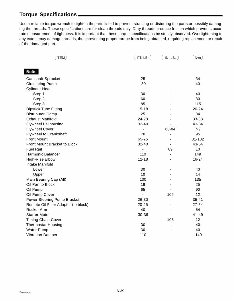
6-39Engine/eng
Torque Specifications
Use a reliable torque wrench to tighten theparts listed to prevent straining or distorting the parts or possibly damag-ing the threads. These specifications are for clean threads only. Dirty threads produce friction which prevents accu-rate measurement of tightness. It is important that these torque specifications be strictly observed. Overtightening toany extent may damage threads, thus preventing proper torque from being obtained, requiring replacement or repairof the damaged part.
ITEM FT. LB. IN. LB. N•m
Bolts
Camshaft Sprocket 25 - 34Circulating Pump 30 - 40Cylinder Head
Step 1 30 - 40Step 2 60 - 80Step 3 85 - 115
Dipstick Tube Fitting 15-18 - 20-24Distributor Clamp 25 - 34Exhaust Manifold 24-28 - 33-38Flywheel Bellhousing 32-40 - 43-54Flywheel Cover - 60-84 7-9Flywheel to Crankshaft 70 - 95Front Mount 65-75 - 81-102Front Mount Bracket to Block 32-40 - 43-54Fuel Rail - 89 10Harmonic Balancer 110 - 149High-Rise Elbow 12-18 - 16-24Intake Manifold
Lower 30 - 40Upper 10 - 14
Main Bearing Cap (All) 100 - 135Oil Pan to Block 18 - 25Oil Pump 65 - 90Oil Pump Cover - 106 12Power Steering Pump Bracket 26-30 - 35-41Remote Oil Filter Adaptor (to block) 20-25 - 27-34Rocker Arm 40 - 54Starter Motor 30-36 - 41-49Timing Chain Cover - 106 12Thermostat Housing 30 - 40Water Pump 30 - 40Vibration Damper 110 -149
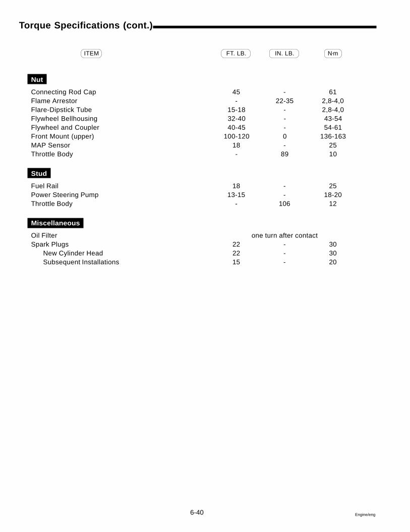
6-40 Engine/eng
Torque Specifications (cont.)
ITEM FT. LB. IN. LB. N•m
Nut
Connecting Rod Cap 45 - 61Flame Arrestor - 22-35 2,8-4,0Flare-Dipstick Tube 15-18 - 2,8-4,0Flywheel Bellhousing 32-40 - 43-54Flywheel and Coupler 40-45 - 54-61Front Mount (upper) 100-120 0 136-163MAP Sensor 18 - 25Throttle Body - 89 10
Stud
Fuel Rail 18 - 25Power Steering Pump 13-15 - 18-20Throttle Body - 106 12
Miscellaneous
Oil Filter one turn after contactSpark Plugs 22 - 30
New Cylinder Head 22 - 30Subsequent Installations 15 - 20
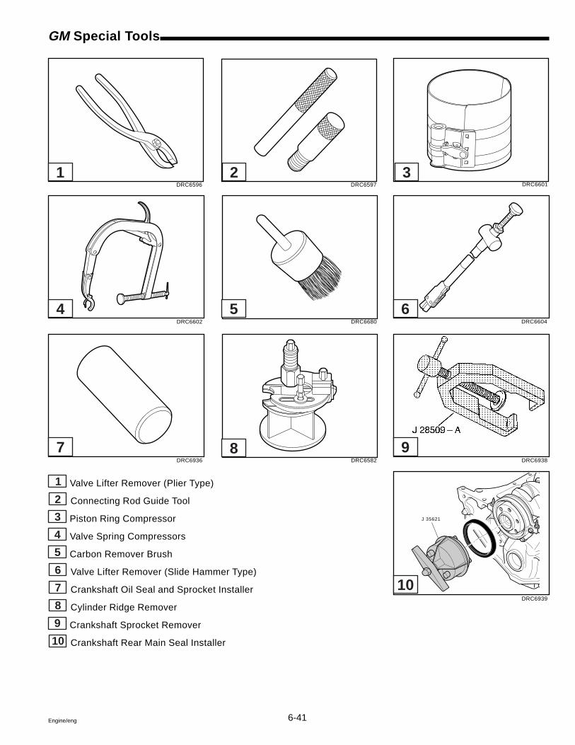
6-41Engine/eng
GM Special Tools
1 Valve Lifter Remover (Plier Type)
2 Connecting Rod Guide Tool
3 Piston Ring Compressor
4 Valve Spring Compressors
5 Carbon Remover Brush
6 Valve Lifter Remover (Slide Hammer Type)
7 Crankshaft Oil Seal and Sprocket Installer
8 Cylinder Ridge Remover
9 Crankshaft Sprocket Remover
10 Crankshaft Rear Main Seal Installer
DRC6596 DRC6597 DRC6601
DRC6604
DRC6938
DRC6939
DRC6602 DRC6680
DRC6936 DRC6582
J 35621
1 2 3
4 5 6
7 8 9
10

6-42 Engine/eng
7-1Engine/eng
Section 77.4 GSi and 8.2 GSi Engines
Table of Contents
7
Camshaft ........................................................................................... 7-15Camshaft Lobe Lift, Measuring ....................................................... 7-19Circulating Pump.............................................................................. 7-24Connecting Rod Bearing Replacement .......................................... 7-21Crankshaft ........................................................................................ 7-20Cylinder Block .................................................................................. 7-23Cylinder Head ..................................................................................... 7-9Engine Coupler Replacement.......................................................... 7-27Engine Specifications ...................................................................... 7-29Exhaust Hose and Intermediate Pipe Replacement ...................... 7-27Exhaust Manifold Replacement ........................................................ 7-5Front Engine Mount Replacement .................................................. 7-24GM Special Tools ................................................................................ 7-2High-Rise Exhaust Elbow Replacement ......................................... 7-25Intake Manifold ................................................................................... 7-3Lubrication System .......................................................................... 7-16Material Required ............................................................................... 7-2Oil Pan ............................................................................................... 7-17Oil Pump ........................................................................................... 7-17Oil Seal Replacement, Rear Main Bearing ..................................... 7-19Piston, Ring and Connecting Rod .................................................. 7-22Remote Engine Oil Filter .................................................................. 7-16Timing Chain, Cover and Seal ......................................................... 7-12Torque Specifications ...................................................................... 7-32Valve Lifter, Hydraulic ........................................................................ 7-6Valve Spring and Seal Repair ............................................................ 7-8
Safety Warnings
Before working on any part of the engine, read the Safety sectionat the end of this manual.
Unless instructed otherwise, always disconnect the battery cablesfrom the battery before working on electrical system (to preventpossible sparks or arcing in the engine compartment).
Before starting engine after repair or maintenance procedures, al-ways make sure engine compartment is free of fuel vapors to pre-vent possible fire and explosion.
When working on an engine that is running or being cranked, useextreme care to avoid getting hands, fingers or clothing caught inthe alternator, power steering and circulating pump belts, pulleysand other moving parts.
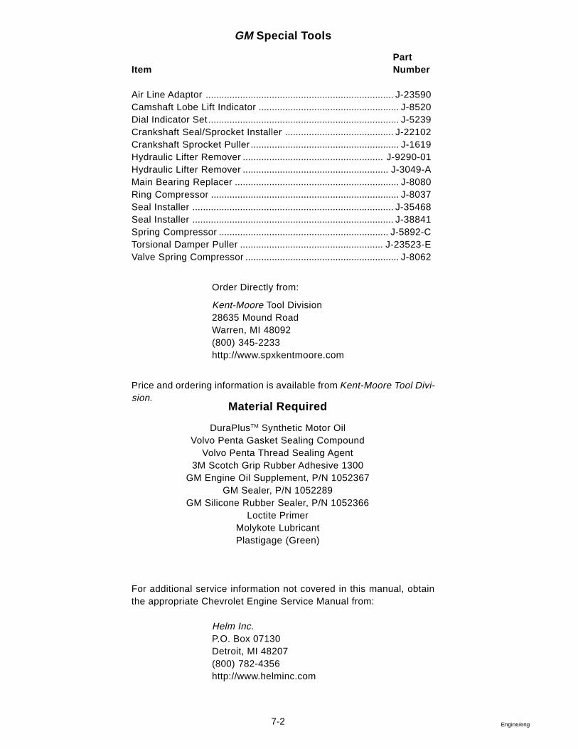
7-2 Engine/eng
Material Required
DuraPlusTM Synthetic Motor OilVolvo Penta Gasket Sealing Compound
Volvo Penta Thread Sealing Agent3M Scotch Grip Rubber Adhesive 1300
GM Engine Oil Supplement, P/N 1052367GM Sealer, P/N 1052289
GM Silicone Rubber Sealer, P/N 1052366Loctite Primer
Molykote LubricantPlastigage (Green)
GM Special Tools
PartItem Number
Air Line Adaptor ....................................................................... J-23590Camshaft Lobe Lift Indicator ..................................................... J-8520Dial Indicator Set ........................................................................ J-5239Crankshaft Seal/Sprocket Installer ......................................... J-22102Crankshaft Sprocket Puller ........................................................ J-1619Hydraulic Lifter Remover ..................................................... J-9290-01Hydraulic Lifter Remover ....................................................... J-3049-AMain Bearing Replacer .............................................................. J-8080Ring Compressor ....................................................................... J-8037Seal Installer ............................................................................ J-35468Seal Installer ............................................................................ J-38841Spring Compressor ................................................................ J-5892-CTorsional Damper Puller ...................................................... J-23523-EValve Spring Compressor .......................................................... J-8062
Order Directly from:
Kent-Moore Tool Division28635 Mound RoadWarren, MI 48092(800) 345-2233http://www.spxkentmoore.com
Price and ordering information is available from Kent-Moore Tool Divi-sion.
For additional service information not covered in this manual, obtainthe appropriate Chevrolet Engine Service Manual from:
Helm Inc.P.O. Box 07130Detroit, MI 48207(800) 782-4356http://www.helminc.com
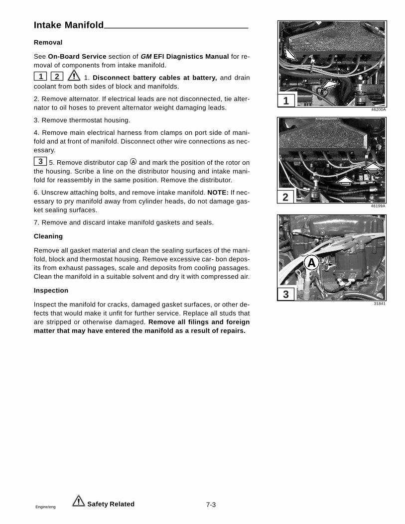
7-3Engine/eng
Intake Manifold
Removal
See On-Board Service section of GM EFI Diagnistics Manual for re-moval of components from intake manifold.
1 2 1. Disconnect battery cables at battery, and draincoolant from both sides of block and manifolds.
2. Remove alternator. If electrical leads are not disconnected, tie alter-nator to oil hoses to prevent alternator weight damaging leads.
3. Remove thermostat housing.
4. Remove main electrical harness from clamps on port side of mani-fold and at front of manifold. Disconnect other wire connections as nec-essary.
3 5. Remove distributor cap A and mark the position of the rotor onthe housing. Scribe a line on the distributor housing and intake mani-fold for reassembly in the same position. Remove the distributor.
6. Unscrew attaching bolts, and remove intake manifold. NOTE: If nec-essary to pry manifold away from cylinder heads, do not damage gas-ket sealing surfaces.
7. Remove and discard intake manifold gaskets and seals.
Cleaning
Remove all gasket material and clean the sealing surfaces of the mani-fold, block and thermostat housing. Remove excessive car- bon depos-its from exhaust passages, scale and deposits from cooling passages.Clean the manifold in a suitable solvent and dry it with compressed air.
Inspection
Inspect the manifold for cracks, damaged gasket surfaces, or other de-fects that would make it unfit for further service. Replace all studs thatare stripped or otherwise damaged. Remove all filings and foreignmatter that may have entered the manifold as a result of repairs.
Safety Related
46200A
46199A
31841
1
2
3
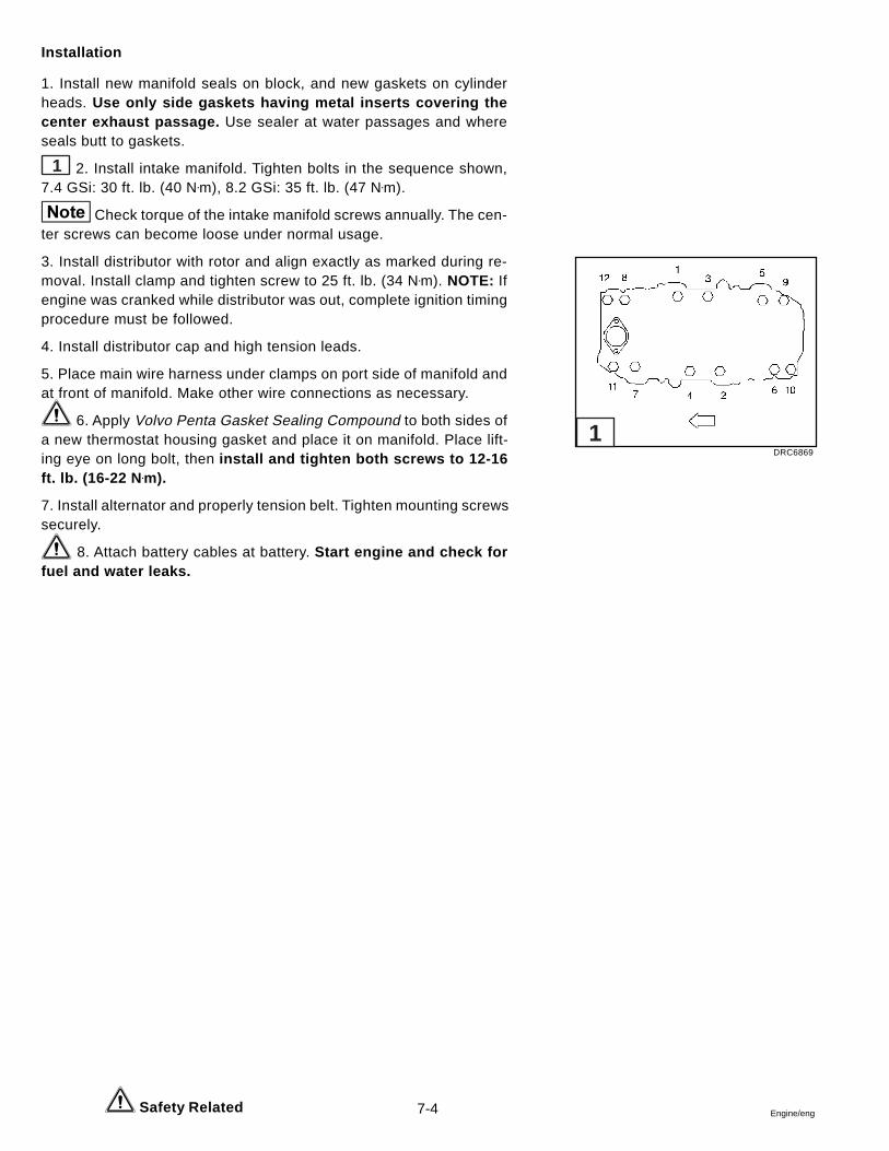
7-4 Engine/eng
Installation
1. Install new manifold seals on block, and new gaskets on cylinderheads. Use only side gaskets having metal inserts covering thecenter exhaust passage. Use sealer at water passages and whereseals butt to gaskets.
1 2. Install intake manifold. Tighten bolts in the sequence shown,7.4 GSi: 30 ft. lb. (40 N•m), 8.2 GSi: 35 ft. lb. (47 N•m).
Check torque of the intake manifold screws annually. The cen-ter screws can become loose under normal usage.
3. Install distributor with rotor and align exactly as marked during re-moval. Install clamp and tighten screw to 25 ft. lb. (34 N•m). NOTE: Ifengine was cranked while distributor was out, complete ignition timingprocedure must be followed.
4. Install distributor cap and high tension leads.
5. Place main wire harness under clamps on port side of manifold andat front of manifold. Make other wire connections as necessary.
6. Apply Volvo Penta Gasket Sealing Compound to both sides ofa new thermostat housing gasket and place it on manifold. Place lift-ing eye on long bolt, then install and tighten both screws to 12-16ft. lb. (16-22 N •m).
7. Install alternator and properly tension belt. Tighten mounting screwssecurely.
8. Attach battery cables at battery. Start engine and check forfuel and water leaks.
Safety Related
DRC6869
1
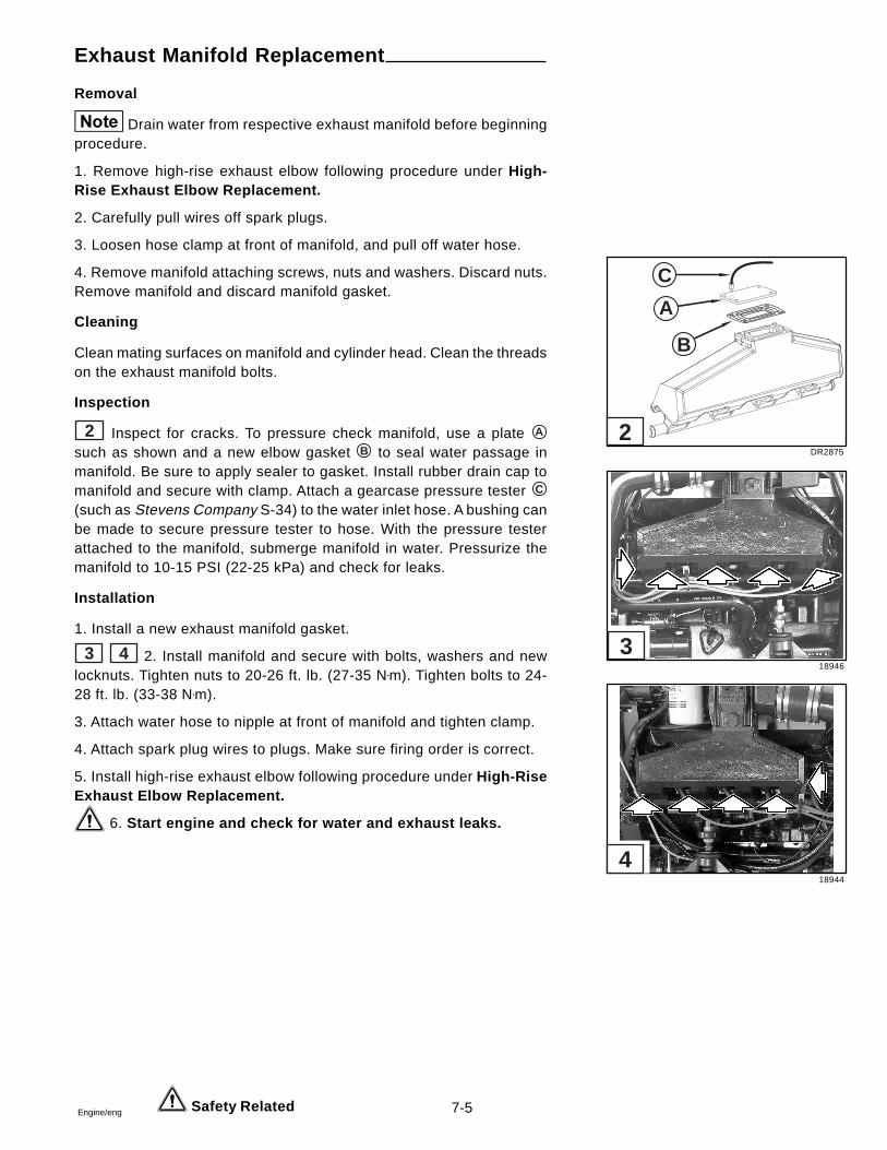
7-5Engine/eng
Exhaust Manifold Replacement
Removal
Drain water from respective exhaust manifold before beginningprocedure.
1. Remove high-rise exhaust elbow following procedure under High-Rise Exhaust Elbow Replacement.
2. Carefully pull wires off spark plugs.
3. Loosen hose clamp at front of manifold, and pull off water hose.
4. Remove manifold attaching screws, nuts and washers. Discard nuts.Remove manifold and discard manifold gasket.
Cleaning
Clean mating surfaces on manifold and cylinder head. Clean the threadson the exhaust manifold bolts.
Inspection
2 Inspect for cracks. To pressure check manifold, use a plate A
such as shown and a new elbow gasket B to seal water passage inmanifold. Be sure to apply sealer to gasket. Install rubber drain cap tomanifold and secure with clamp. Attach a gearcase pressure tester C
(such as Stevens Company S-34) to the water inlet hose. A bushing canbe made to secure pressure tester to hose. With the pressure testerattached to the manifold, submerge manifold in water. Pressurize themanifold to 10-15 PSI (22-25 kPa) and check for leaks.
Installation
1. Install a new exhaust manifold gasket.
3 4 2. Install manifold and secure with bolts, washers and newlocknuts. Tighten nuts to 20-26 ft. lb. (27-35 N•m). Tighten bolts to 24-28 ft. lb. (33-38 N•m).
3. Attach water hose to nipple at front of manifold and tighten clamp.
4. Attach spark plug wires to plugs. Make sure firing order is correct.
5. Install high-rise exhaust elbow following procedure under High-RiseExhaust Elbow Replacement.
6. Start engine and check for water and exhaust leaks.
Safety Related
DR2875
18946
18944
C
A
B
2
3
4
7-6 Engine/eng
Hydraulic Valve Lifter
Checking Hydraulic Valve Lifter
When checking hydraulic valve lifters, rememberthat grit, sludge, var-nish, or other foreign matter will seriously affect their operation. If anyforeign substance is found in the lifters or engine where it may becirculated by the lubrication system, a thorough cleaning job must bedone to avoid a repetition of lifter trouble.
To help prevent lifter trouble, the engine oil and oil filter must be changedas recommended in General Information Section. The engine oil mustbe heavy-duty type (for Service SG) and must also conform to Gen-eral Motors Standard 6094-M to avoid detrimental formation of sludgeand varnish. We recommend DuraPlusTM Synthetic Motor Oil. The boatowner should be specifically advised of these requirements when theunit is delivered. Faulty valve lifter operation usually appears underone of the following conditions:
1. Rapping Noise Only When Engine is Started:
When the engine is stopped, any lifter on a camshaft lobe is underpressure of the valve spring; therefore, leak down or escape of oilfrom the lower chamber can occur. When the engine is started, a fewseconds may be required to fill the lifter, particularly in colder weather.If noise occurs only occasionally, it may be considered normal, requir-ing no correction. If noise occurs frequently, however, check for eitheroil too heavy for prevailing temperatures, or excessive varnish in lifters.
2. Intermittent Rapping Noise:
An intermittent rapping noise that appears and disappears every fewseconds indicates leakage at check ball seat due to foreign particles,varnish, or defective surface of check ball or seat.
3. Noise at Idle and Low Speed:
If one or more valve lifters are noisy at idle speed and up to approxi-mately 1200 RPM, but quiet at higher speeds, it indicates excessiveleakdown rate orfaultycheckball seatorplunger.With engine idling, lifterswith excessive leak down rate may be spotted by pressing down oneach rocker arm above the push rod with equal pressure. Reconditionor replace noisy lifters.
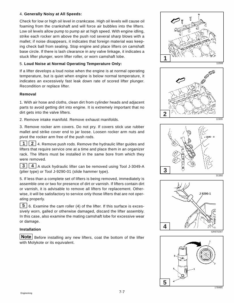
7-7Engine/eng
4. Generally Noisy at All Speeds:
Check for low or high oil level in crankcase. High oil levels will cause oilfoaming from the crankshaft and will force air bubbles into the lifters.Low oil levels allow pump to pump air at high speed. With engine idling,strike each rocker arm above the push rod several sharp blows with amallet; if noise disappears, it indicates that foreign material was keep-ing check ball from seating. Stop engine and place lifters on camshaftbase circle. If there is lash clearance in any valve linkage, it indicates astuck lifter plunger, worn lifter roller, or worn camshaft lobe.
5. Loud Noise at Normal Operating Temperature Only:
If a lifter develops a loud noise when the engine is at normal operatingtemperature, but is quiet when engine is below normal temperature, itindicates an excessively fast leak down rate of scored lifter plunger.Recondition or replace lifter.
Removal
1. With air hose and cloths, clean dirt from cylinder heads and adjacentparts to avoid getting dirt into engine. It is extremely important that nodirt gets into the valve lifters.
2. Remove intake manifold. Remove exhaust manifolds.
3. Remove rocker arm covers. Do not pry. If covers stick use rubbermallet and strike cover end to jar loose. Loosen rocker arm nuts andpivot the rocker arm free of the push rods.
1 2 4. Remove push rods. Remove the hydraulic lifter guides andlifters that require service one at a time and place them in an organizerrack. The lifters must be installed in the same bore from which theywere removed.
3 4 A stuck hydraulic lifter can be removed using Tool J-3049-A(plier type) or Tool J-9290-01 (slide hammer type).
5. If less than a complete set of lifters is being removed, immediately isassemble one or two for presence of dirt or varnish. If lifters contain dirtor varnish, it is advisable to remove all lifters for replacement. Other-wise, it will be satisfactory to service only those lifters that are not oper-ating properly.
5 6. Examine the cam roller (4) of the lifter. If this surface is exces-sively worn, galled or otherwise damaged, discard the lifter assembly.In this case, also examine the mating camshaft lobe for excessive wearor damage.
Installation
Before installing any new lifters, coat the bottom of the lifterwith Molykote or its equivalent.
11508
11509
31350
GR970297
178485
5
4
3
2
1
J 9290-1
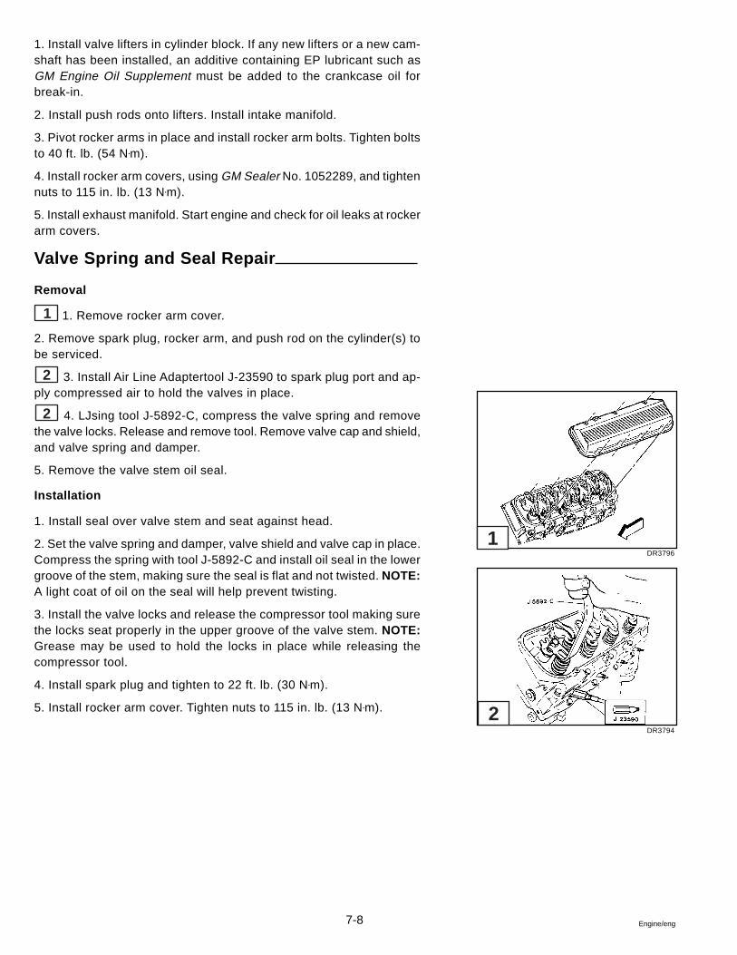
7-8 Engine/eng
1. Install valve lifters in cylinder block. If any new lifters or a new cam-shaft has been installed, an additive containing EP lubricant such asGM Engine Oil Supplement must be added to the crankcase oil forbreak-in.
2. Install push rods onto lifters. Install intake manifold.
3. Pivot rocker arms in place and install rocker arm bolts. Tighten boltsto 40 ft. lb. (54 N•m).
4. Install rocker arm covers, using GM Sealer No. 1052289, and tightennuts to 115 in. lb. (13 N•m).
5. Install exhaust manifold. Start engine and check for oil leaks at rockerarm covers.
Valve Spring and Seal Repair
Removal
1 1. Remove rocker arm cover.
2. Remove spark plug, rocker arm, and push rod on the cylinder(s) tobe serviced.
2 3. Install Air Line Adaptertool J-23590 to spark plug port and ap-ply compressed air to hold the valves in place.
2 4. LJsing tool J-5892-C, compress the valve spring and removethe valve locks. Release and remove tool. Remove valve cap and shield,and valve spring and damper.
5. Remove the valve stem oil seal.
Installation
1. Install seal over valve stem and seat against head.
2. Set the valve spring and damper, valve shield and valve cap in place.Compress the spring with tool J-5892-C and install oil seal in the lowergroove of the stem, making sure the seal is flat and not twisted. NOTE:A light coat of oil on the seal will help prevent twisting.
3. Install the valve locks and release the compressor tool making surethe locks seat properly in the upper groove of the valve stem. NOTE:Grease may be used to hold the locks in place while releasing thecompressor tool.
4. Install spark plug and tighten to 22 ft. lb. (30 N•m).
5. Install rocker arm cover. Tighten nuts to 115 in. lb. (13 N•m).
DR3796
DR3794
1
2
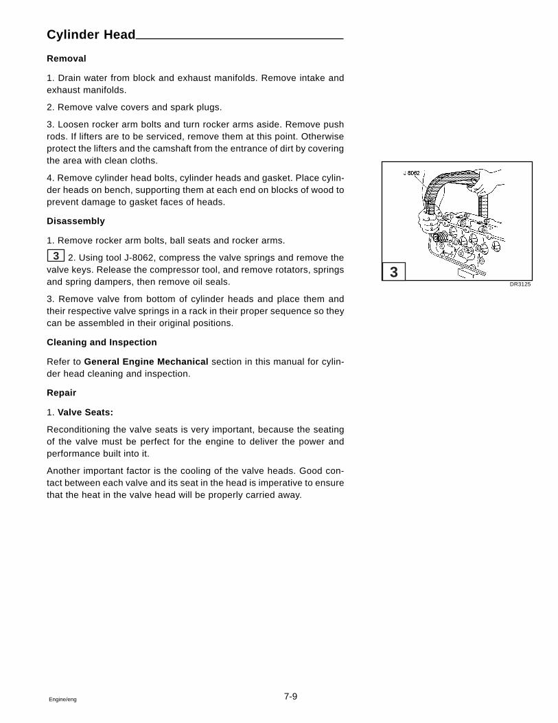
7-9Engine/eng
Cylinder Head
Removal
1. Drain water from block and exhaust manifolds. Remove intake andexhaust manifolds.
2. Remove valve covers and spark plugs.
3. Loosen rocker arm bolts and turn rocker arms aside. Remove pushrods. If lifters are to be serviced, remove them at this point. Otherwiseprotect the lifters and the camshaft from the entrance of dirt by coveringthe area with clean cloths.
4. Remove cylinder head bolts, cylinder heads and gasket. Place cylin-der heads on bench, supporting them at each end on blocks of wood toprevent damage to gasket faces of heads.
Disassembly
1. Remove rocker arm bolts, ball seats and rocker arms.
3 2. Using tool J-8062, compress the valve springs and remove thevalve keys. Release the compressor tool, and remove rotators, springsand spring dampers, then remove oil seals.
3. Remove valve from bottom of cylinder heads and place them andtheir respective valve springs in a rack in their proper sequence so theycan be assembled in their original positions.
Cleaning and Inspection
Refer to General Engine Mechanical section in this manual for cylin-der head cleaning and inspection.
Repair
1. Valve Seats:
Reconditioning the valve seats is very important, because the seatingof the valve must be perfect for the engine to deliver the power andperformance built into it.
Another important factor is the cooling of the valve heads. Good con-tact between each valve and its seat in the head is imperative to ensurethat the heat in the valve head will be properly carried away.
DR3125
3
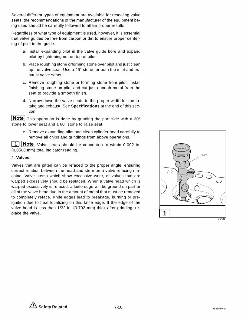
7-10 Engine/eng Safety Related
Several different types of equipment are available for resealing valveseats; the recommendations of the manufacturer of the equipment be-ing used should be carefully followed to attain proper results.
Regardless of what type of equipment is used, however, it is essentialthat valve guides be free from carbon or dirt to ensure proper center-ing of pilot in the guide.
a. Install expanding pilot in the valve guide bore and expandpilot by tightening nut on top of pilot.
b. Place roughing stone orforming stone over pilot and just cleanup the valve seat. Use a 46° stone for both the inlet and ex-haust valve seats.
c. Remove roughing stone or forming stone from pilot, installfinishing stone on pilot and cut just enough metal from theseat to provide a smooth finish.
d. Narrow down the valve seats to the proper width for the in-take and exhaust. See Specifications at the end of this sec-tion.
This operation is done by grinding the port side with a 30°stone to lower seat and a 60° stone to raise seat.
e. Remove expanding pilot and clean cylinder head carefully toremove all chips and grindings from above operations.
1 Valve seats should be concentric to within 0.002 in.(0,0508 mm) total indicator reading.
2. Valves:
Valves that are pitted can be refaced to the proper angle, ensuringcorrect relation between the head and stern on a valve refacing ma-chine. Valve stems which show excessive wear, or valves that arewarped excessively should be replaced. When a valve head which iswarped excessively is refaced, a knife edge will be ground on part orall of the valve head due to the amount of metal that must be removedto completely reface. Knife edges lead to breakage, burning or pre-ignition due to heat localizing on this knife edge. If the edge of thevalve head is less than 1/32 in. (0.792 mm) thick after grinding, re-place the valve.
10425
J 8001
1
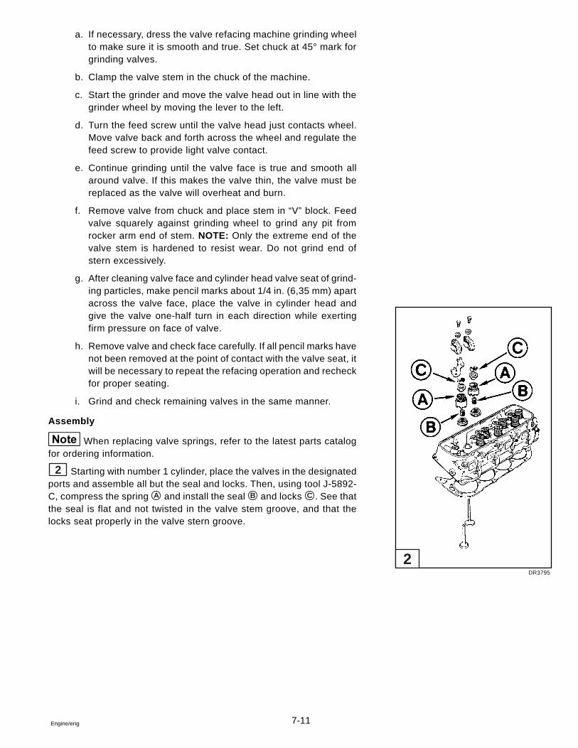
7-11Engine/eng
a. If necessary, dress the valve refacing machine grinding wheelto make sure it is smooth and true. Set chuck at 45° mark forgrinding valves.
b. Clamp the valve stem in the chuck of the machine.
c. Start the grinder and move the valve head out in line with thegrinder wheel by moving the lever to the left.
d. Turn the feed screw until the valve head just contacts wheel.Move valve back and forth across the wheel and regulate thefeed screw to provide light valve contact.
e. Continue grinding until the valve face is true and smooth allaround valve. If this makes the valve thin, the valve must bereplaced as the valve will overheat and burn.
f. Remove valve from chuck and place stem in “V” block. Feedvalve squarely against grinding wheel to grind any pit fromrocker arm end of stem. NOTE: Only the extreme end of thevalve stem is hardened to resist wear. Do not grind end ofstern excessively.
g. After cleaning valve face and cylinder head valve seat of grind-ing particles, make pencil marks about 1/4 in. (6,35 mm) apartacross the valve face, place the valve in cylinder head andgive the valve one-half turn in each direction while exertingfirm pressure on face of valve.
h. Remove valve and check face carefully. If all pencil marks havenot been removed at the point of contact with the valve seat, itwill be necessary to repeat the refacing operation and recheckfor proper seating.
i. Grind and check remaining valves in the same manner.
Assembly
When replacing valve springs, refer to the latest parts catalogfor ordering information.
2 Starting with number 1 cylinder, place the valves in the designatedports and assemble all but the seal and locks. Then, using tool J-5892-C, compress the spring A and install the seal B and locks C . See thatthe seal is flat and not twisted in the valve stem groove, and that thelocks seat properly in the valve stern groove.
DR3795
2
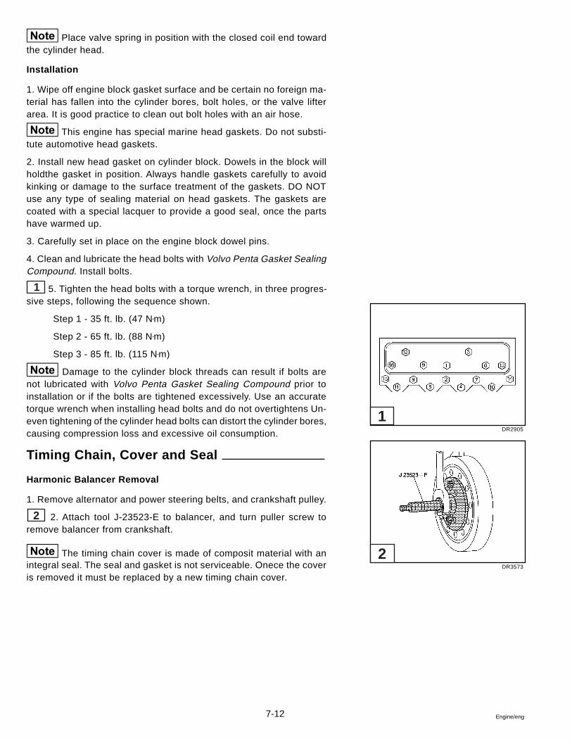
7-12 Engine/eng
Place valve spring in position with the closed coil end towardthe cylinder head.
Installation
1. Wipe off engine block gasket surface and be certain no foreign ma-terial has fallen into the cylinder bores, bolt holes, or the valve lifterarea. It is good practice to clean out bolt holes with an air hose.
This engine has special marine head gaskets. Do not substi-tute automotive head gaskets.
2. Install new head gasket on cylinder block. Dowels in the block willholdthe gasket in position. Always handle gaskets carefully to avoidkinking or damage to the surface treatment of the gaskets. DO NOTuse any type of sealing material on head gaskets. The gaskets arecoated with a special lacquer to provide a good seal, once the partshave warmed up.
3. Carefully set in place on the engine block dowel pins.
4. Clean and lubricate the head bolts with Volvo Penta Gasket SealingCompound. Install bolts.
1 5. Tighten the head bolts with a torque wrench, in three progres-sive steps, following the sequence shown.
Step 1 - 35 ft. lb. (47 N•m)
Step 2 - 65 ft. lb. (88 N•m)
Step 3 - 85 ft. lb. (115 N•m)
Damage to the cylinder block threads can result if bolts arenot lubricated with Volvo Penta Gasket Sealing Compound prior toinstallation or if the bolts are tightened excessively. Use an accuratetorque wrench when installing head bolts and do not overtightens Un-even tightening of the cylinder head bolts can distort the cylinder bores,causing compression loss and excessive oil consumption.
Timing Chain, Cover and Seal
Harmonic Balancer Removal
1. Remove alternator and power steering belts, and crankshaft pulley.
2 2. Attach tool J-23523-E to balancer, and turn puller screw toremove balancer from crankshaft.
The timing chain cover is made of composit material with anintegral seal. The seal and gasket is not serviceable. Onece the coveris removed it must be replaced by a new timing chain cover.
DR2905
DR3573
1
2
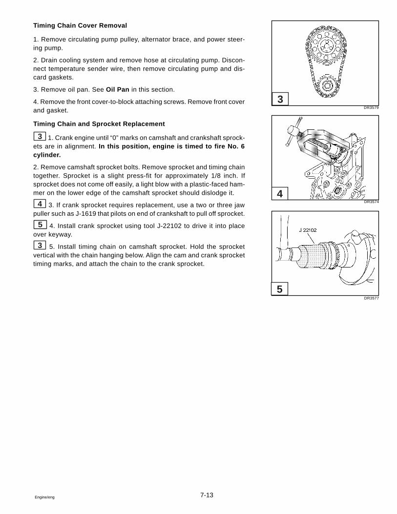
7-13Engine/eng
Timing Chain Cover Removal
1. Remove circulating pump pulley, alternator brace, and power steer-ing pump.
2. Drain cooling system and remove hose at circulating pump. Discon-nect temperature sender wire, then remove circulating pump and dis-card gaskets.
3. Remove oil pan. See Oil Pan in this section.
4. Remove the front cover-to-block attaching screws. Remove front coverand gasket.
Timing Chain and Sprocket Replacement
3 1. Crank engine until “0” marks on camshaft and crankshaft sprock-ets are in alignment. In this position, engine is timed to fire No. 6cylinder.
2. Remove camshaft sprocket bolts. Remove sprocket and timing chaintogether. Sprocket is a slight press-fit for approximately 1/8 inch. Ifsprocket does not come off easily, a light blow with a plastic-faced ham-mer on the lower edge of the camshaft sprocket should dislodge it.
4 3. If crank sprocket requires replacement, use a two or three jawpuller such as J-1619 that pilots on end of crankshaft to pull off sprocket.
5 4. Install crank sprocket using tool J-22102 to drive it into placeover keyway.
3 5. Install timing chain on camshaft sprocket. Hold the sprocketvertical with the chain hanging below. Align the cam and crank sprockettiming marks, and attach the chain to the crank sprocket.
DR3579
DR3574
DR3577
3
4
5
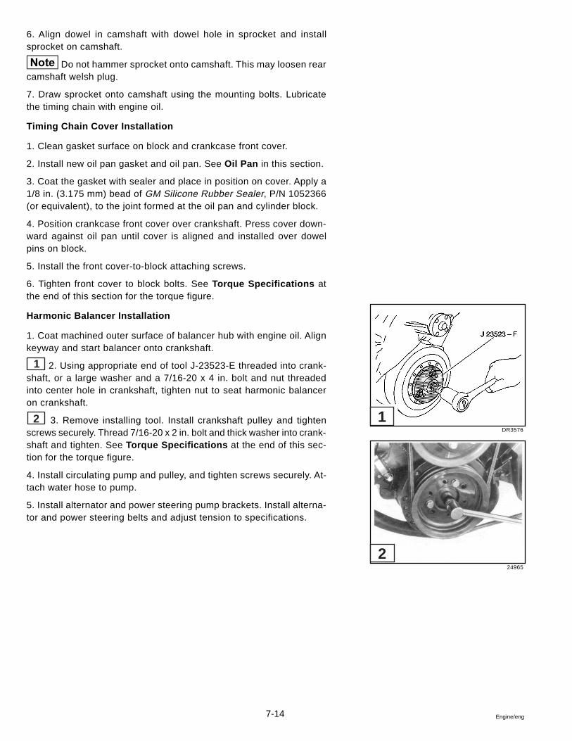
7-14 Engine/eng
6. Align dowel in camshaft with dowel hole in sprocket and installsprocket on camshaft.
Do not hammer sprocket onto camshaft. This may loosen rearcamshaft welsh plug.
7. Draw sprocket onto camshaft using the mounting bolts. Lubricatethe timing chain with engine oil.
Timing Chain Cover Installation
1. Clean gasket surface on block and crankcase front cover.
2. Install new oil pan gasket and oil pan. See Oil Pan in this section.
3. Coat the gasket with sealer and place in position on cover. Apply a1/8 in. (3.175 mm) bead of GM Silicone Rubber Sealer, P/N 1052366(or equivalent), to the joint formed at the oil pan and cylinder block.
4. Position crankcase front cover over crankshaft. Press cover down-ward against oil pan until cover is aligned and installed over dowelpins on block.
5. Install the front cover-to-block attaching screws.
6. Tighten front cover to block bolts. See Torque Specifications atthe end of this section for the torque figure.
Harmonic Balancer Installation
1. Coat machined outer surface of balancer hub with engine oil. Alignkeyway and start balancer onto crankshaft.
1 2. Using appropriate end of tool J-23523-E threaded into crank-shaft, or a large washer and a 7/16-20 x 4 in. bolt and nut threadedinto center hole in crankshaft, tighten nut to seat harmonic balanceron crankshaft.
2 3. Remove installing tool. Install crankshaft pulley and tightenscrews securely. Thread 7/16-20 x 2 in. bolt and thick washer into crank-shaft and tighten. See Torque Specifications at the end of this sec-tion for the torque figure.
4. Install circulating pump and pulley, and tighten screws securely. At-tach water hose to pump.
5. Install alternator and power steering pump brackets. Install alterna-tor and power steering belts and adjust tension to specifications.
DR3576
24965
1
2
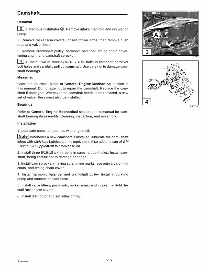
7-15Engine/eng
Camshaft
Removal
3 1. Remove distributor A . Remove intake manifold and circulatingpump.
2. Remove rocker arm covers, loosen rocker arms, then remove pushrods and valve lifters.
3. Remove crankshaft pulley, harmonic balancer, timing chain cover,timing chain, and camshaft sprocket.
4 4. Install two or three 5/16-18 x 4 in. bolts in camshaft sprocketbolt holes and carefully pull out camshaft. Use care not to damage cam-shaft bearings.
Measure:
Camshaft Journals. Refer to General Engine Mechanical section inthis manual. Do not attempt to repair the camshaft. Replace the cam-shaft if damaged. Whenever the camshaft needs to be replaced, a newset of valve lifters must also be installed.
Bearings
Refer to General Engine Mechanical section in this manual for cam-shaft bearing disassembly, cleaning, inspection, and assembly.
Installation
1. Lubricate camshaft journals with engine oil.
Whenever a new camshaft is installed, lubricate the cam- shaftlobes with Molykote Lubricant or its equivalent. Also add one can of GMEngine Oil Supplement to crankcase oil.
2. Install three 5/16-18 x 4 in. bolts in camshaft bolt holes. Install cam-shaft, being careful not to damage bearings.
3. Install cam sprocket (making sure timing marks face outward), timingchain, and timing chain cover.
4. Install harmonic balancer and crankshaft pulley. Install circulatingpump and connect coolant hose.
5. Install valve lifters, push rods, rocker arms, and intake manifold. In-stall rocker arm covers.
6. Install distributor and set initial timing.
28257
DR3790
3
4
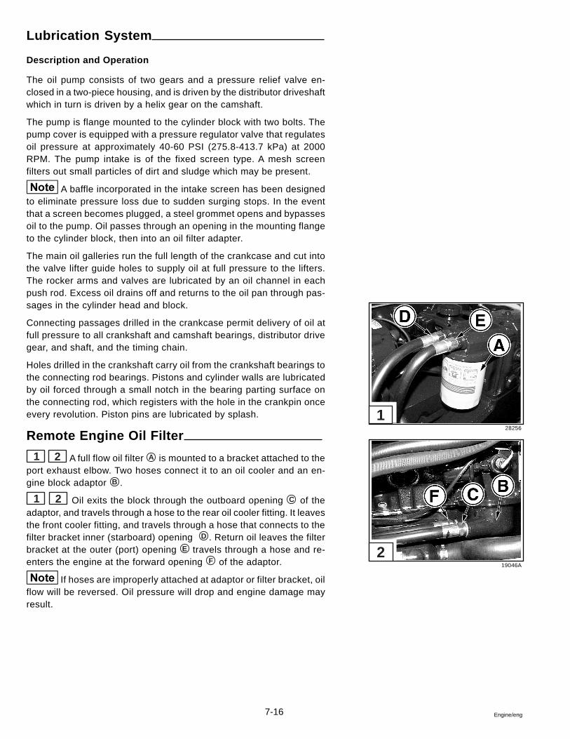
7-16 Engine/eng
Lubrication System
Description and Operation
The oil pump consists of two gears and a pressure relief valve en-closed in a two-piece housing, and is driven by the distributor driveshaftwhich in turn is driven by a helix gear on the camshaft.
The pump is flange mounted to the cylinder block with two bolts. Thepump cover is equipped with a pressure regulator valve that regulatesoil pressure at approximately 40-60 PSI (275.8-413.7 kPa) at 2000RPM. The pump intake is of the fixed screen type. A mesh screenfilters out small particles of dirt and sludge which may be present.
A baffle incorporated in the intake screen has been designedto eliminate pressure loss due to sudden surging stops. In the eventthat a screen becomes plugged, a steel grommet opens and bypassesoil to the pump. Oil passes through an opening in the mounting flangeto the cylinder block, then into an oil filter adapter.
The main oil galleries run the full length of the crankcase and cut intothe valve lifter guide holes to supply oil at full pressure to the lifters.The rocker arms and valves are lubricated by an oil channel in eachpush rod. Excess oil drains off and returns to the oil pan through pas-sages in the cylinder head and block.
Connecting passages drilled in the crankcase permit delivery of oil atfull pressure to all crankshaft and camshaft bearings, distributor drivegear, and shaft, and the timing chain.
Holes drilled in the crankshaft carry oil from the crankshaft bearings tothe connecting rod bearings. Pistons and cylinder walls are lubricatedby oil forced through a small notch in the bearing parting surface onthe connecting rod, which registers with the hole in the crankpin onceevery revolution. Piston pins are lubricated by splash.
Remote Engine Oil Filter
1 2 A full flow oil filter A is mounted to a bracket attached to theport exhaust elbow. Two hoses connect it to an oil cooler and an en-gine block adaptor B .
1 2 Oil exits the block through the outboard opening C of theadaptor, and travels through a hose to the rear oil cooler fitting. It leavesthe front cooler fitting, and travels through a hose that connects to thefilter bracket inner (starboard) opening D . Return oil leaves the filterbracket at the outer (port) opening E travels through a hose and re-enters the engine at the forward opening F of the adaptor.
If hoses are improperly attached at adaptor or filter bracket, oilflow will be reversed. Oil pressure will drop and engine damage mayresult.
28256
19046A
1
2
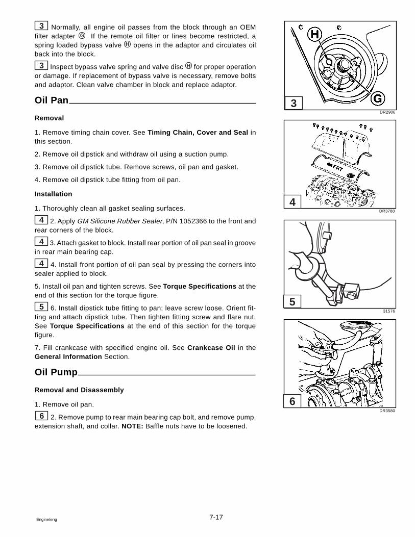
7-17Engine/eng
3 Normally, all engine oil passes from the block through an OEMfilter adapter G . If the remote oil filter or lines become restricted, aspring loaded bypass valve H opens in the adaptor and circulates oilback into the block.
3 Inspect bypass valve spring and valve disc H for proper operationor damage. If replacement of bypass valve is necessary, remove boltsand adaptor. Clean valve chamber in block and replace adaptor.
Oil Pan
Removal
1. Remove timing chain cover. See Timing Chain, Cover and Seal inthis section.
2. Remove oil dipstick and withdraw oil using a suction pump.
3. Remove oil dipstick tube. Remove screws, oil pan and gasket.
4. Remove oil dipstick tube fitting from oil pan.
Installation
1. Thoroughly clean all gasket sealing surfaces.
4 2. Apply GM Silicone Rubber Sealer, P/N 1052366 to the front andrear corners of the block.
4 3. Attach gasket to block. Install rear portion of oil pan seal in groovein rear main bearing cap.
4 4. Install front portion of oil pan seal by pressing the corners intosealer applied to block.
5. Install oil pan and tighten screws. See Torque Specifications at theend of this section for the torque figure.
5 6. Install dipstick tube fitting to pan; leave screw loose. Orient fit-ting and attach dipstick tube. Then tighten fitting screw and flare nut.See Torque Specifications at the end of this section for the torquefigure.
7. Fill crankcase with specified engine oil. See Crankcase Oil in theGeneral Information Section.
Oil Pump
Removal and Disassembly
1. Remove oil pan.
6 2. Remove pump to rear main bearing cap bolt, and remove pump,extension shaft, and collar. NOTE: Baffle nuts have to be loosened.
DR2906
DR3788
31576
DR3580
3
4
5
6
7-18 Engine/eng
3. Disconnect pump shaft from extension. Remove four cover attach-ing screws, cover, gasket, idler gear and drive gear, and shaft.
4. Remove pressure regulator valve and valve parts.
5. If the pickup screen or pipe need replacing, replace the entire pumpand pickup screen assembly.
6. Wash all parts in cleaning solvent and dry using compressed air.
Inspection
Should any of the following conditions be found during inspection op-erations, the pump and pickup screen assembly should be replaced.
1. Inspect pump body for cracks or excessive wear. Inspect oil pumpgears for excessive wear or damage.
2. Check shaft for looseness in the housing. Check inside of cover forwear that would permit oil to leak past the ends of gears.
3. Check the oil pickup screen for damage to screen or relief grommet.Check for oil in the air chamber.
4. Check pressure regulator valve plunger for fit in cover.
Assembly and Installation
1. Place drive gear and shaft in pump body. Install idler gear so thatsmooth side of gear will be toward the cover.
2. Install a new pump to cover gasket to ensure correct end clearanceof the gears.
3. Install cover and attaching screws. Tighten screws to 80 in. lb. (9N•m), and check to see that shaft turns freely.
4. Install regulator valve plunger, spring, retainer, and pin.
5. Assemble collar end of extension shaft assembly over pumpdriveshaft, aligning tang of extension shaft with slot in end of pumpdriveshaft.
6. Assemble pump and extension shaft to rear main bearing cap, align-ing slot on top end of extension shaft with drive tang on lower end ofdistributor shaft. NOTE: Oil pump should slide easily into place. If not,remove and relocate slot or locate other problem. Install mountingscrews and tighten. See Torque Specifications at the end of this sec-tion for the torque figure.
7. Tighten baffle nuts.
8. Install oil pan using new gasket. Connect oil drain tube.
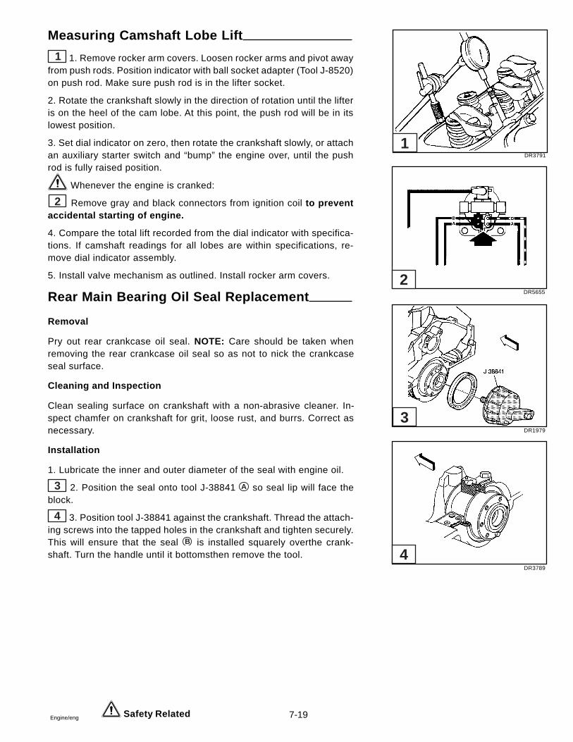
7-19Engine/eng
Measuring Camshaft Lobe Lift
1 1. Remove rocker arm covers. Loosen rocker arms and pivot awayfrom push rods. Position indicator with ball socket adapter (Tool J-8520)on push rod. Make sure push rod is in the lifter socket.
2. Rotate the crankshaft slowly in the direction of rotation until the lifteris on the heel of the cam lobe. At this point, the push rod will be in itslowest position.
3. Set dial indicator on zero, then rotate the crankshaft slowly, or attachan auxiliary starter switch and “bump” the engine over, until the pushrod is fully raised position.
Whenever the engine is cranked:
2 Remove gray and black connectors from ignition coil to preventaccidental starting of engine.
4. Compare the total lift recorded from the dial indicator with specifica-tions. If camshaft readings for all lobes are within specifications, re-move dial indicator assembly.
5. Install valve mechanism as outlined. Install rocker arm covers.
Rear Main Bearing Oil Seal Replacement
Removal
Pry out rear crankcase oil seal. NOTE: Care should be taken whenremoving the rear crankcase oil seal so as not to nick the crankcaseseal surface.
Cleaning and Inspection
Clean sealing surface on crankshaft with a non-abrasive cleaner. In-spect chamfer on crankshaft for grit, loose rust, and burrs. Correct asnecessary.
Installation
1. Lubricate the inner and outer diameter of the seal with engine oil.
3 2. Position the seal onto tool J-38841 A so seal lip will face theblock.
4 3. Position tool J-38841 against the crankshaft. Thread the attach-ing screws into the tapped holes in the crankshaft and tighten securely.This will ensure that the seal B is installed squarely overthe crank-shaft. Turn the handle until it bottomsthen remove the tool.
Safety Related
DR3791
DR5655
DR1979
DR3789
4
3
2
1
7-20 Engine/eng
Crankshaft
Description
Main bearings are of the precision insert type and do not utilize shimsfor adjustment. If clearances are found to be excessive, a new bear-ing, both upper and lower halves, will be required. Bearings are avail-able in standard size and 0.001 in. (0.0254 mm), 0.002 in. (0.0508mm), 0.010 in. (0.245 mm) and 0.020 in. (0.508 mm) undersize.
Selective fitting of both rod and main bearing inserts is necessary inproduction in order to obtain close tolerances. For this reason youmay find one-half of a standard insert with one-half of a 0.001 in. (0.0254mm) undersize insert which will decrease the clearance 0.0005 in.(0.0127 mm) from using a full standard bearing.
When a production crankshaft cannot be precision fitted by this method,it is then ground 0.009 in. (0.2286 mm) undersize on only those mainjournals that cannot be properly fitted. All journals will not necessarilybe ground undersize. A 0.009 in. (0.2286 mm) undersize bearing and0.010 in. (0.245 mm) undersize bearing may be used for precisionfitting in the same manner as previously described.
If, for any reason, main bearing caps are replaced, shimmingmay be necessary. Laminated shims for each cap are available forservice. Shim requirement will be determined by bearing clearance.
Cleaning, Inspection and Repair
Refer to General Engine Mechanical section in this manualfor cleaning, inspection, and measurements.
In general, (except No. 1 bearing) the lower half of the bearing showsa greater wear and the most distress from fatigue. If upon inspectionthe lower half is suitable for use, it can be assumed that the upper halfis also satisfactory. If the lower half shows evidence of wear or dam-age, both upper and lower halves should be replaced. Never replaceone half without replacing the other half.
These dimensions should be checked with a micrometer for out-of-round, taper or undersize. If the journals exceed 0.001 in. (0.0254 mm)out-of-round, or taper, the crankshaft should be replaced or recondi-tioned to an undersize figure that will enable the installation of under-size precision type bearings.
The crankshaft should also be checked for runout. To perform this op-eration, support the crankshaft at the front and rear main bearing jour-nals in “V” blocks, and indicate the runout of both the rear intermedi-ate and front intermediate journals, using a dial indicator. The runoutlimit of each of these journals is 0.002 in. (0.0508 mm). If the runoutexceeds 0.002 in. (0.0508 mm), the crankshaft must be repaired orreplaced.
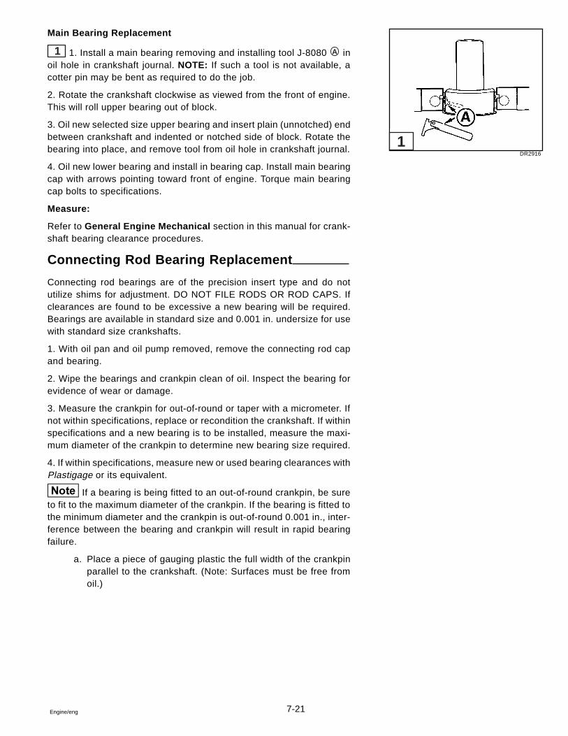
7-21Engine/eng
Main Bearing Replacement
1 1. Install a main bearing removing and installing tool J-8080 A inoil hole in crankshaft journal. NOTE: If such a tool is not available, acotter pin may be bent as required to do the job.
2. Rotate the crankshaft clockwise as viewed from the front of engine.This will roll upper bearing out of block.
3. Oil new selected size upper bearing and insert plain (unnotched) endbetween crankshaft and indented or notched side of block. Rotate thebearing into place, and remove tool from oil hole in crankshaft journal.
4. Oil new lower bearing and install in bearing cap. Install main bearingcap with arrows pointing toward front of engine. Torque main bearingcap bolts to specifications.
Measure:
Refer to General Engine Mechanical section in this manual for crank-shaft bearing clearance procedures.
Connecting Rod Bearing Replacement
Connecting rod bearings are of the precision insert type and do notutilize shims for adjustment. DO NOT FILE RODS OR ROD CAPS. Ifclearances are found to be excessive a new bearing will be required.Bearings are available in standard size and 0.001 in. undersize for usewith standard size crankshafts.
1. With oil pan and oil pump removed, remove the connecting rod capand bearing.
2. Wipe the bearings and crankpin clean of oil. Inspect the bearing forevidence of wear or damage.
3. Measure the crankpin for out-of-round or taper with a micrometer. Ifnot within specifications, replace or recondition the crankshaft. If withinspecifications and a new bearing is to be installed, measure the maxi-mum diameter of the crankpin to determine new bearing size required.
4. If within specifications, measure new or used bearing clearances withPlastigage or its equivalent.
If a bearing is being fitted to an out-of-round crankpin, be sureto fit to the maximum diameter of the crankpin. If the bearing is fitted tothe minimum diameter and the crankpin is out-of-round 0.001 in., inter-ference between the bearing and crankpin will result in rapid bearingfailure.
a. Place a piece of gauging plastic the full width of the crankpinparallel to the crankshaft. (Note: Surfaces must be free fromoil.)
DR2916
1
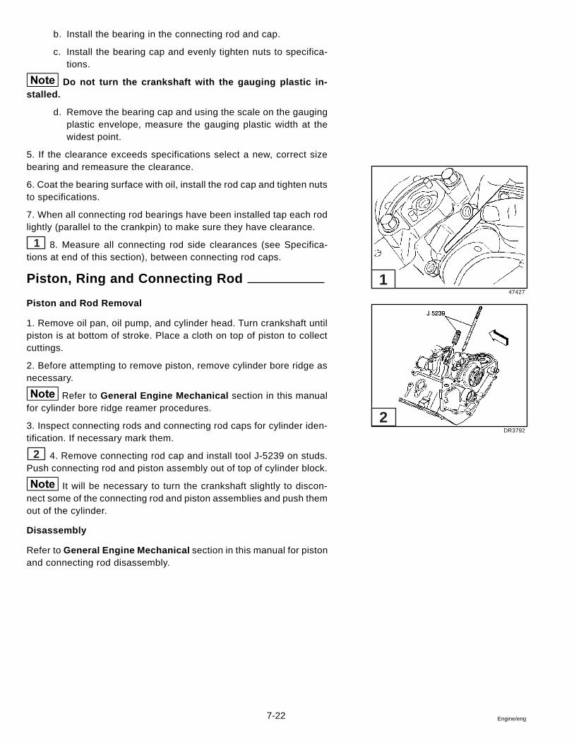
7-22 Engine/eng
b. Install the bearing in the connecting rod and cap.
c. Install the bearing cap and evenly tighten nuts to specifica-tions.
Do not turn the crankshaft with the gauging plastic in-stalled.
d. Remove the bearing cap and using the scale on the gaugingplastic envelope, measure the gauging plastic width at thewidest point.
5. If the clearance exceeds specifications select a new, correct sizebearing and remeasure the clearance.
6. Coat the bearing surface with oil, install the rod cap and tighten nutsto specifications.
7. When all connecting rod bearings have been installed tap each rodlightly (parallel to the crankpin) to make sure they have clearance.
1 8. Measure all connecting rod side clearances (see Specifica-tions at end of this section), between connecting rod caps.
Piston, Ring and Connecting Rod
Piston and Rod Removal
1. Remove oil pan, oil pump, and cylinder head. Turn crankshaft untilpiston is at bottom of stroke. Place a cloth on top of piston to collectcuttings.
2. Before attempting to remove piston, remove cylinder bore ridge asnecessary.
Refer to General Engine Mechanical section in this manualfor cylinder bore ridge reamer procedures.
3. Inspect connecting rods and connecting rod caps for cylinder iden-tification. If necessary mark them.
2 4. Remove connecting rod cap and install tool J-5239 on studs.Push connecting rod and piston assembly out of top of cylinder block.
It will be necessary to turn the crankshaft slightly to discon-nect some of the connecting rod and piston assemblies and push themout of the cylinder.
Disassembly
Refer to General Engine Mechanical section in this manual for pistonand connecting rod disassembly.
47427
DR3792
1
2
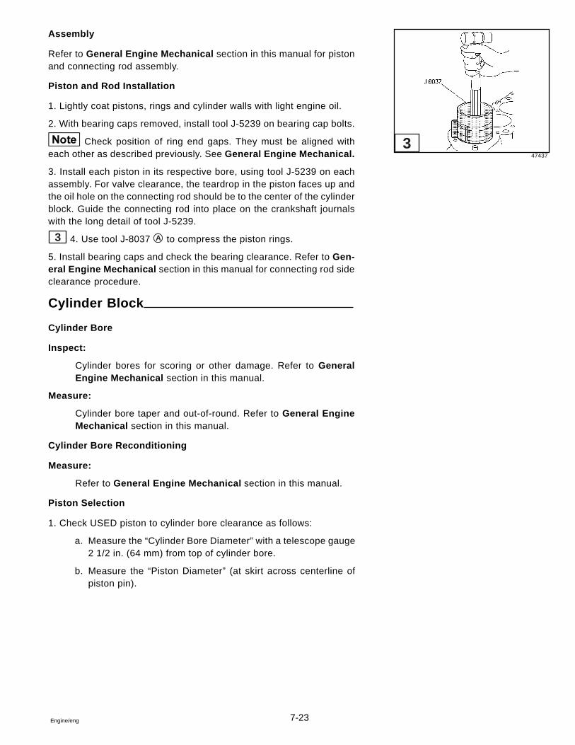
7-23Engine/eng
Assembly
Refer to General Engine Mechanical section in this manual for pistonand connecting rod assembly.
Piston and Rod Installation
1. Lightly coat pistons, rings and cylinder walls with light engine oil.
2. With bearing caps removed, install tool J-5239 on bearing cap bolts.
Check position of ring end gaps. They must be aligned witheach other as described previously. See General Engine Mechanical.
3. Install each piston in its respective bore, using tool J-5239 on eachassembly. For valve clearance, the teardrop in the piston faces up andthe oil hole on the connecting rod should be to the center of the cylinderblock. Guide the connecting rod into place on the crankshaft journalswith the long detail of tool J-5239.
3 4. Use tool J-8037 A to compress the piston rings.
5. Install bearing caps and check the bearing clearance. Refer to Gen-eral Engine Mechanical section in this manual for connecting rod sideclearance procedure.
Cylinder Block
Cylinder Bore
Inspect:
Cylinder bores for scoring or other damage. Refer to GeneralEngine Mechanical section in this manual.
Measure:
Cylinder bore taper and out-of-round. Refer to General EngineMechanical section in this manual.
Cylinder Bore Reconditioning
Measure:
Refer to General Engine Mechanical section in this manual.
Piston Selection
1. Check USED piston to cylinder bore clearance as follows:
a. Measure the “Cylinder Bore Diameter” with a telescope gauge2 1/2 in. (64 mm) from top of cylinder bore.
b. Measure the “Piston Diameter” (at skirt across centerline ofpiston pin).
47437
3
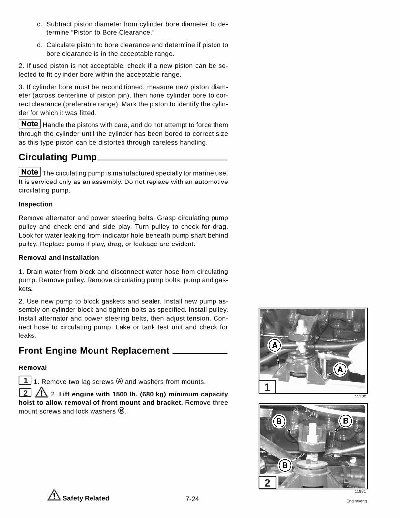
7-24 Engine/eng
c. Subtract piston diameter from cylinder bore diameter to de-termine “Piston to Bore Clearance.”
d. Calculate piston to bore clearance and determine if piston tobore clearance is in the acceptable range.
2. If used piston is not acceptable, check if a new piston can be se-lected to fit cylinder bore within the acceptable range.
3. If cylinder bore must be reconditioned, measure new piston diam-eter (across centerline of piston pin), then hone cylinder bore to cor-rect clearance (preferable range). Mark the piston to identify the cylin-der for which it was fitted.
Handle the pistons with care, and do not attempt to force themthrough the cylinder until the cylinder has been bored to correct sizeas this type piston can be distorted through careless handling.
Circulating Pump
The circulating pump is manufactured specially for marine use.It is serviced only as an assembly. Do not replace with an automotivecirculating pump.
Inspection
Remove alternator and power steering belts. Grasp circulating pumppulley and check end and side play. Turn pulley to check for drag.Look for water leaking from indicator hole beneath pump shaft behindpulley. Replace pump if play, drag, or leakage are evident.
Removal and Installation
1. Drain water from block and disconnect water hose from circulatingpump. Remove pulley. Remove circulating pump bolts, pump and gas-kets.
2. Use new pump to block gaskets and sealer. Install new pump as-sembly on cylinder block and tighten bolts as specified. Install pulley.Install alternator and power steering belts, then adjust tension. Con-nect hose to circulating pump. Lake or tank test unit and check forleaks.
Front Engine Mount Replacement
Removal
1 1. Remove two lag screws A and washers from mounts.
2 2. Lift engine with 1500 lb. (680 kg) minimum capacityhoist to allow removal of front mount and bracket. Remove threemount screws and lock washers B .
Safety Related
11982
11981
1
2
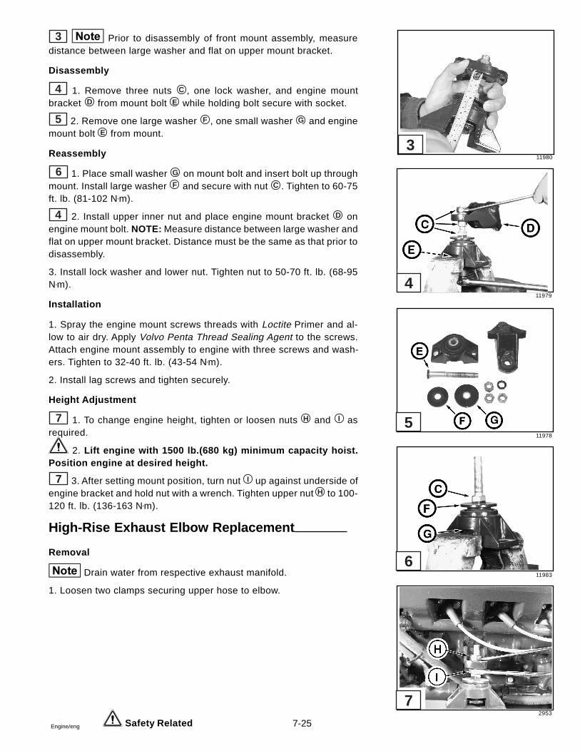
7-25Engine/eng
3 Prior to disassembly of front mount assembly, measuredistance between large washer and flat on upper mount bracket.
Disassembly
4 1. Remove three nuts C , one lock washer, and engine mountbracket D from mount bolt E while holding bolt secure with socket.
5 2. Remove one large washer F , one small washer G and enginemount bolt E from mount.
Reassembly
6 1. Place small washer G on mount bolt and insert bolt up throughmount. Install large washer F and secure with nut C . Tighten to 60-75ft. lb. (81-102 N•m).
4 2. Install upper inner nut and place engine mount bracket D onengine mount bolt. NOTE: Measure distance between large washer andflat on upper mount bracket. Distance must be the same as that prior todisassembly.
3. Install lock washer and lower nut. Tighten nut to 50-70 ft. lb. (68-95N•m).
Installation
1. Spray the engine mount screws threads with Loctite Primer and al-low to air dry. Apply Volvo Penta Thread Sealing Agent to the screws.Attach engine mount assembly to engine with three screws and wash-ers. Tighten to 32-40 ft. lb. (43-54 N•m).
2. Install lag screws and tighten securely.
Height Adjustment
7 1. To change engine height, tighten or loosen nuts H and I asrequired.
2. Lift engine with 1500 lb.(680 kg) minimum capacity hoist.Position engine at desired height.
7 3. After setting mount position, turn nut I up against underside ofengine bracket and hold nut with a wrench. Tighten upper nut H to 100-120 ft. lb. (136-163 N•m).
High-Rise Exhaust Elbow Replacement
Removal
Drain water from respective exhaust manifold.
1. Loosen two clamps securing upper hose to elbow.
Safety Related
11980
11979
11978
11983
2953
7
6
5
4
3
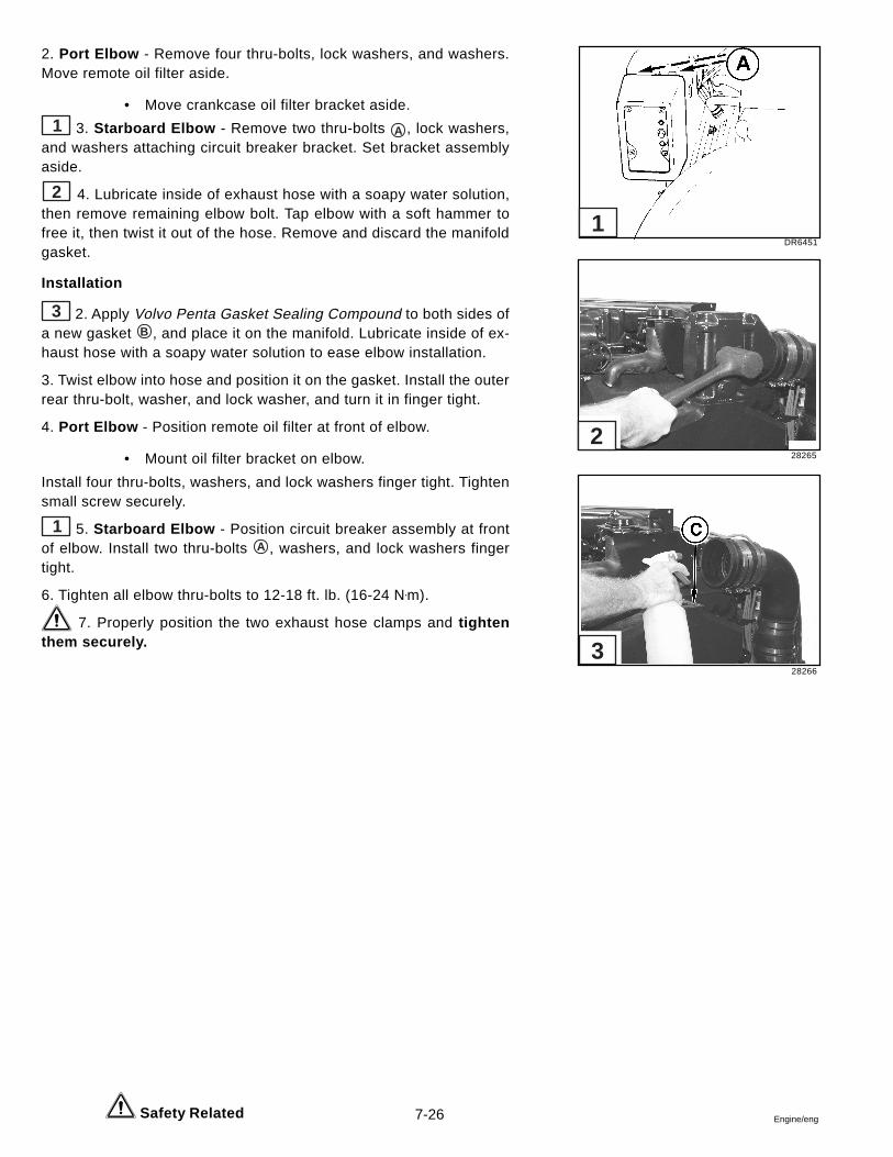
7-26 Engine/eng
2. Port Elbow - Remove four thru-bolts, lock washers, and washers.Move remote oil filter aside.
• Move crankcase oil filter bracket aside.
1 3. Starboard Elbow - Remove two thru-bolts A , lock washers,and washers attaching circuit breaker bracket. Set bracket assemblyaside.
2 4. Lubricate inside of exhaust hose with a soapy water solution,then remove remaining elbow bolt. Tap elbow with a soft hammer tofree it, then twist it out of the hose. Remove and discard the manifoldgasket.
Installation
3 2. Apply Volvo Penta Gasket Sealing Compound to both sides ofa new gasket B , and place it on the manifold. Lubricate inside of ex-haust hose with a soapy water solution to ease elbow installation.
3. Twist elbow into hose and position it on the gasket. Install the outerrear thru-bolt, washer, and lock washer, and turn it in finger tight.
4. Port Elbow - Position remote oil filter at front of elbow.
• Mount oil filter bracket on elbow.
Install four thru-bolts, washers, and lock washers finger tight. Tightensmall screw securely.
1 5. Starboard Elbow - Position circuit breaker assembly at frontof elbow. Install two thru-bolts A , washers, and lock washers fingertight.
6. Tighten all elbow thru-bolts to 12-18 ft. lb. (16-24 N•m).
7. Properly position the two exhaust hose clamps and tightenthem securely.
Safety Related
DR6451
28265
28266
1
2
3
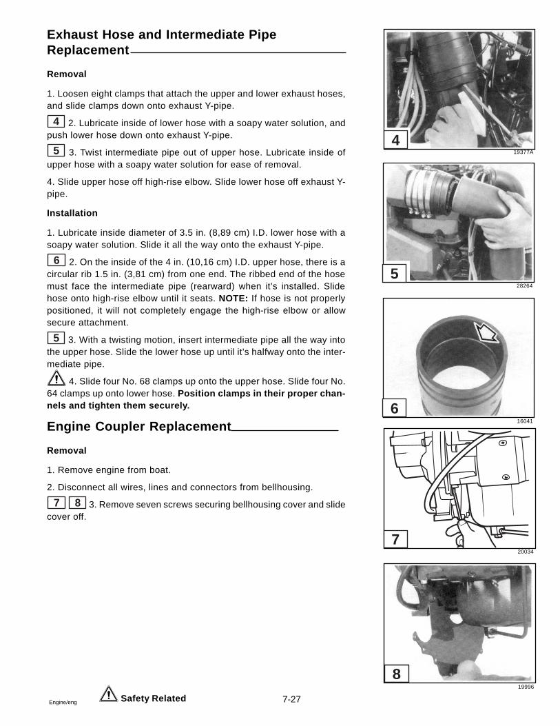
7-27Engine/eng
Exhaust Hose and Intermediate PipeReplacement
Removal
1. Loosen eight clamps that attach the upper and lower exhaust hoses,and slide clamps down onto exhaust Y-pipe.
4 2. Lubricate inside of lower hose with a soapy water solution, andpush lower hose down onto exhaust Y-pipe.
5 3. Twist intermediate pipe out of upper hose. Lubricate inside ofupper hose with a soapy water solution for ease of removal.
4. Slide upper hose off high-rise elbow. Slide lower hose off exhaust Y-pipe.
Installation
1. Lubricate inside diameter of 3.5 in. (8,89 cm) I.D. lower hose with asoapy water solution. Slide it all the way onto the exhaust Y-pipe.
6 2. On the inside of the 4 in. (10,16 cm) I.D. upper hose, there is acircular rib 1.5 in. (3,81 cm) from one end. The ribbed end of the hosemust face the intermediate pipe (rearward) when it’s installed. Slidehose onto high-rise elbow until it seats. NOTE: If hose is not properlypositioned, it will not completely engage the high-rise elbow or allowsecure attachment.
5 3. With a twisting motion, insert intermediate pipe all the way intothe upper hose. Slide the lower hose up until it’s halfway onto the inter-mediate pipe.
4. Slide four No. 68 clamps up onto the upper hose. Slide four No.64 clamps up onto lower hose. Position clamps in their proper chan-nels and tighten them securely.
Engine Coupler Replacement
Removal
1. Remove engine from boat.
2. Disconnect all wires, lines and connectors from bellhousing.
7 8 3. Remove seven screws securing bellhousing cover and slidecover off.
Safety Related
19377A
28264
16041
6
5
4
20034
19996
7
8
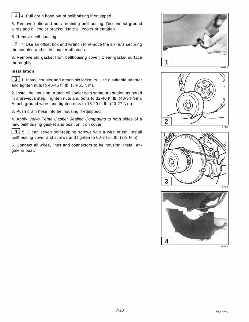
7-28 Engine/eng
1 4. Pull drain hose out of bellhotising if equipped.
5. Remove bolts and nuts retaining bellhousing. Disconnect groundwires and oil cooler bracket. Note oil cooler orientation.
6. Remove bell housing.
2 7. Use an offset box end wrench to remove the six nuts securingthe coupler, and slide coupler off studs.
8. Remove old gasket from bellhousing cover. Clean gasket surfacethoroughly.
Installation
3 1. Install coupler and attach six locknuts. Use a suitable adaptorand tighten nuts to 40-45 ft. lb. (54-61 N•m).
2. Install bellhousing. Attach oil cooler with same orientation as notedin a previous step. Tighten nuts and bolts to 32-40 ft. lb. (43-54 N•m).Attach ground wires and tighten nuts to 15-20 ft. lb. (20-27 N•m).
3. Push drain hose into bellhousing if equipped.
4. Apply Volvo Penta Gasket Sealing Compound to both sides of anew bellhousing gasket and position it on cover.
4 5. Clean seven self-tapping screws with a wire brush. Installbellhousing cover and screws and tighten to 60-84 in. lb. (7-9 N•m).
6. Connect all wires, lines and connectors to bellhousing. Install en-gine in boat.
19842
6712
6714
19083
4
3
2
1
7-29Engine/eng
Engine Specifications
7.4 GSi and 8.2 GSi Models
General Information:
Type - No. of Cylinder ..................................................................................................................................90° - V-8Valve Arrangement ......................................................................................................................................... In headBore and Stroke
7.4 GSi ................................................................................................... 4.250 x 4.000 in. (107.95 x 101.6 mm)8.2 GSi .................................................................................................. 4.468 x 4.000 in. (1 13.48 x 101.6 mm)
Piston Displacement7.4 GSi ........................................................................................................................ 7.4 liter/454 Cubic Inches8.2 GSi ..................................................................................................................... 8.2 Liters/502 Cubic Inches
Cylinder Numbers - Front to RearStarboard Bank ........................................................................................................................................ 2-4-6-8Port Bank .................................................................................................................................................. 1-3-5-7
Firing Order ........................................................................................................................................ 1-8-4-3-6-5-7-2Compression Ratio
7.4 GSi .......................................................................................................................................................... 8.6:18.2 GSi .......................................................................................................................................................... 8.8:1
Water Temperature Control .................................................................................................................... ThermostatThermostat Opens at .......................................................................................................................... 140° F (60° C)Alternator Belt Adjustment ...................................................................................1/4-1/2 in. give w/finger pressureFull Throttle Operation Range
7.4 GSi ..................................................................................................................................... 4800 - 5200 RPM8.2 GSi ..................................................................................................................................... 4600 - 5000 RPM
Pistons:
Production Clearance7.4 GSi .................................................................................................. 0.003 - 0.004 in. (0.0762 - 0.1016 mm)8.2 GSi .................................................................................................. 0.004 - 0.005 in. (0.1016 - 0.1270 mm)
Service Limit ................................................................................................................... 0.005 in. (0.127 mm) Max.
Piston Rings. Compression:
Production Groove ClearanceTop .................................................................................................... 0.0012 - 0.0029 in. (0.0304 - 0.0736 mm)2nd .................................................................................................... 0.0012 - 0.0029 in. (0.0304 - 0.0736 mm)
Service Groove Clearance (both) ................................................................................... + 0.001 in. (+0.0254 mm)Gap
Top ........................................................................................................... 0.010 - 0.018 in. (0.254 - 0.475 mm)2nd ............................................................................................................ 0.016 - 0.024 in. (0.406 - 0.609 mm)
Service (both) ..................................................................................................................... + 0.010 in. (+0.254 mm)
Piston Rings. Oil:
Groove ClearanceProduction ............................................................................................ 0.005 - 0.0065 in. (0.127 - 0.1651 mm)Service ........................................................................................................................ + 0.001 in. (+0.0254 mm)
GapProduction ................................................................................................ 0.010 - 0.030 in. (0.254 - 0.762 mm)Service .......................................................................................................................... + 0.010 in. (+0.254 mm)
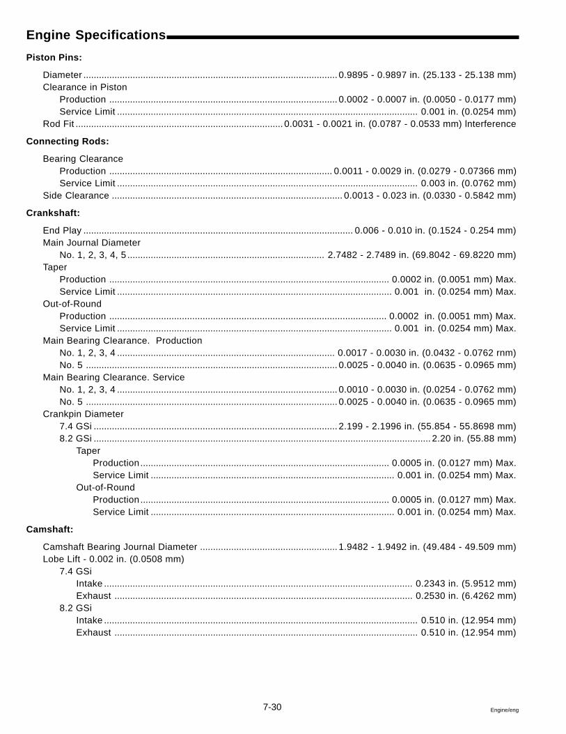
7-30 Engine/eng
Engine Specifications
Piston Pins:
Diameter .................................................................................................. 0.9895 - 0.9897 in. (25.133 - 25.138 mm)Clearance in Piston
Production ........................................................................................ 0.0002 - 0.0007 in. (0.0050 - 0.0177 mm)Service Limit .................................................................................................................... 0.001 in. (0.0254 mm)
Rod Fit ................................................................................ 0.0031 - 0.0021 in. (0.0787 - 0.0533 mm) lnterference
Connecting Rods:
Bearing ClearanceProduction ...................................................................................... 0.0011 - 0.0029 in. (0.0279 - 0.07366 mm)Service Limit .................................................................................................................... 0.003 in. (0.0762 mm)
Side Clearance ......................................................................................... 0.0013 - 0.023 in. (0.0330 - 0.5842 mm)
Crankshaft:
End Play ........................................................................................................ 0.006 - 0.010 in. (0.1524 - 0.254 mm)Main Journal Diameter
No. 1, 2, 3, 4, 5 ............................................................................ 2.7482 - 2.7489 in. (69.8042 - 69.8220 mm)Taper
Production ............................................................................................................ 0.0002 in. (0.0051 mm) Max.Service Limit .......................................................................................................... 0.001 in. (0.0254 mm) Max.
Out-of-RoundProduction ........................................................................................................... 0.0002 in. (0.0051 mm) Max.Service Limit .......................................................................................................... 0.001 in. (0.0254 mm) Max.
Main Bearing Clearance. ProductionNo. 1, 2, 3, 4 .................................................................................... 0.0017 - 0.0030 in. (0.0432 - 0.0762 rnm)No. 5 ................................................................................................. 0.0025 - 0.0040 in. (0.0635 - 0.0965 mm)
Main Bearing Clearance. ServiceNo. 1, 2, 3, 4 ..................................................................................... 0.0010 - 0.0030 in. (0.0254 - 0.0762 mm)No. 5 ................................................................................................. 0.0025 - 0.0040 in. (0.0635 - 0.0965 mm)
Crankpin Diameter7.4 GSi .............................................................................................. 2.199 - 2.1996 in. (55.854 - 55.8698 mm)8.2 GSi .................................................................................................................................. 2.20 in. (55.88 mm)
TaperProduction ................................................................................................ 0.0005 in. (0.0127 mm) Max.Service Limit .............................................................................................. 0.001 in. (0.0254 mm) Max.
Out-of-RoundProduction ................................................................................................ 0.0005 in. (0.0127 mm) Max.Service Limit .............................................................................................. 0.001 in. (0.0254 mm) Max.
Camshaft:
Camshaft Bearing Journal Diameter ..................................................... 1.9482 - 1.9492 in. (49.484 - 49.509 mm)Lobe Lift - 0.002 in. (0.0508 mm)
7.4 GSiIntake ....................................................................................................................... 0.2343 in. (5.9512 mm)Exhaust ................................................................................................................... 0.2530 in. (6.4262 mm)
8.2 GSiIntake ......................................................................................................................... 0.510 in. (12.954 mm)Exhaust ..................................................................................................................... 0.510 in. (12.954 mm)
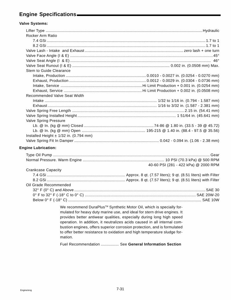
7-31Engine/eng
Engine Specifications
Valve Systems:
Lifter Type ....................................................................................................................................................HydraulicRocker Arm Ratio
7.4 GSi ...................................................................................................................................................... 1.7 to 18.2 GSi ...................................................................................................................................................... 1.7 to 1
Valve Lash - Intake and Exhaust ............................................................................................. zero lash + one turnValve Face Angle (I & E) .......................................................................................................................................45°Valve Seat Angle (I & E) ..................................................................................................................................... 46°Valve Seat Runout (I & E) ............................................................................................ 0.002 in. (0.0508 mm) Max.Stem to Guide Clearance
Intake, Production ............................................................................ 0.0010 - 0.0027 in. (0.0254 - 0.0270 mm)Exhaust, Production ......................................................................... 0.0012 - 0.0029 in. (0.0304 - 0.0736 mm)Intake, Service .............................................................................Hi Limit Production + 0.001 in. (0.0254 mm)Exhaust, Service ..........................................................................Hi Limit Production + 0.002 in. (0.0508 mm)
Recommended Valve Seat WidthIntake .......................................................................................................... 1/32 to 1/16 in. (0.794 - 1.587 mm)Exhaust ....................................................................................................... 1/16 to 3/32 in. (1.587 - 2.381 mm)
Valve Spring Free Length .......................................................................................................... 2.15 in. (54.41 mm)Valve Spring Installed Height ............................................................................................. 1 51/64 in. (45.641 mm)Valve Spring Pressure
Lb. @ In. (kg @ mm) Closed .................................................................. 74-86 @ 1.80 in. (33.5 - 39 @ 45.72)Lb. @ In. (kg @ mm) Open ............................................................ 195-215 @ 1.40 in. (88.4 - 97.5 @ 35.56)
Installed Height ± 1/32 in. (0.794 mm)Valve Spring Fit In Damper ................................................................................ 0.042 - 0.094 in. (1.06 - 2.38 mm)
Engine Lubrication:
Type Oil Pump .................................................................................................................................................... GearNormal Pressure. Warm Engine ............................................................................. 10 PSI (70.3 kPa) @ 500 RPM
40-60 PSI (281 - 422 kPa) @ 2000 RPMCrankcase Capacity
7.4 GSi .......................................................................... Approx. 8 qt. (7.57 liters); 9 qt. (8.51 liters) with Filter8.2 GSi .......................................................................... Approx. 8 qt. (7.57 liters); 9 qt. (8.51 liters) with Filter
Oil Grade Recommended32° F (0° C) and Above ............................................................................................................................ SAE 300° F to 32° F (-18° C to 0° C) ......................................................................................................... SAE 20W-20Below 0° F (-18° C) .............................................................................................................................. SAE 10W
We recommend DuraPlusTM Synthetic Motor Oil, which is specially for-mulated for heavy duty marine use, and ideal for stern drive engines. Itprovides better antiwear qualities, especially during long high speedoperation. In addition, it neutralizes acids caused in all internal com-bustion engines, offers superior corrosion protection, and is formulatedto offer better resistance to oxidation and high temperature sludge for-mation.
Fuel Recommendation ................. See General Information Section
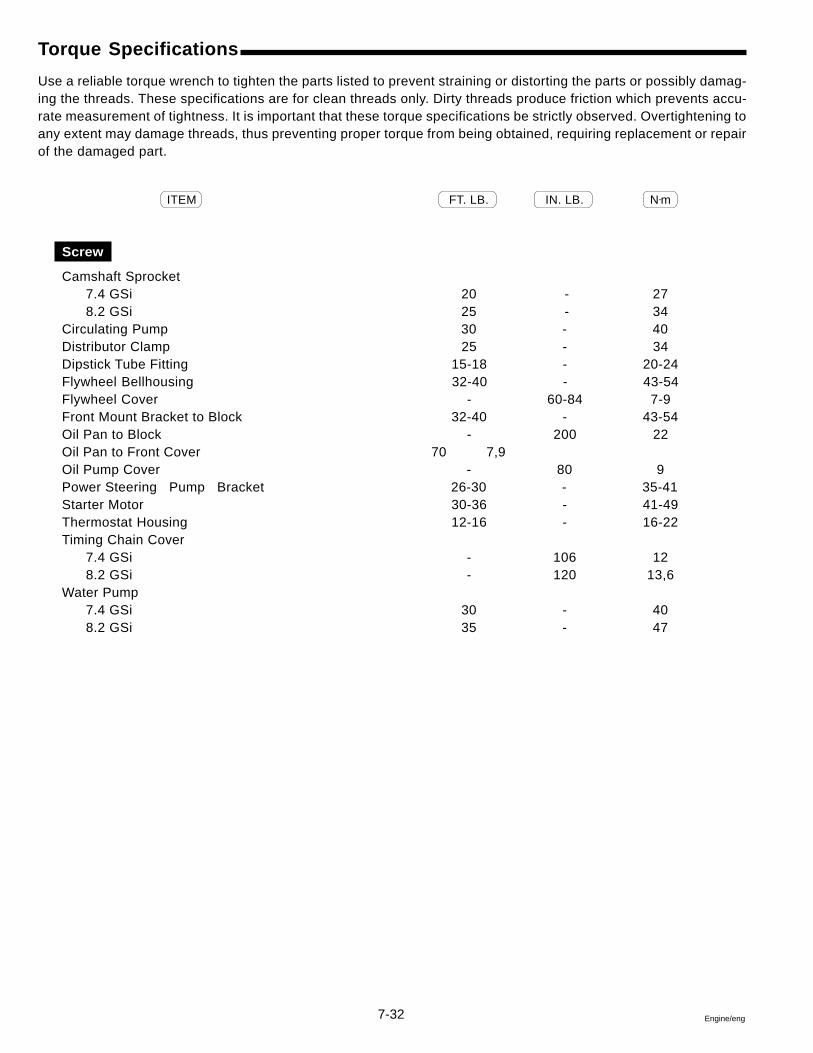
7-32 Engine/eng
Torque Specifications
Use a reliable torque wrench to tighten the parts listed to prevent straining or distorting the parts or possibly damag-ing the threads. These specifications are for clean threads only. Dirty threads produce friction which prevents accu-rate measurement of tightness. It is important that these torque specifications be strictly observed. Overtightening toany extent may damage threads, thus preventing proper torque from being obtained, requiring replacement or repairof the damaged part.
ITEM FT. LB. IN. LB. N•m
Screw
Camshaft Sprocket7.4 GSi 20 - 278.2 GSi 25 - 34
Circulating Pump 30 - 40Distributor Clamp 25 - 34Dipstick Tube Fitting 15-18 - 20-24Flywheel Bellhousing 32-40 - 43-54Flywheel Cover - 60-84 7-9Front Mount Bracket to Block 32-40 - 43-54Oil Pan to Block - 200 22Oil Pan to Front Cover 70 7,9Oil Pump Cover - 80 9Power Steering Pump Bracket 26-30 - 35-41Starter Motor 30-36 - 41-49Thermostat Housing 12-16 - 16-22Timing Chain Cover
7.4 GSi - 106 128.2 GSi - 120 13,6
Water Pump7.4 GSi 30 - 408.2 GSi 35 - 47
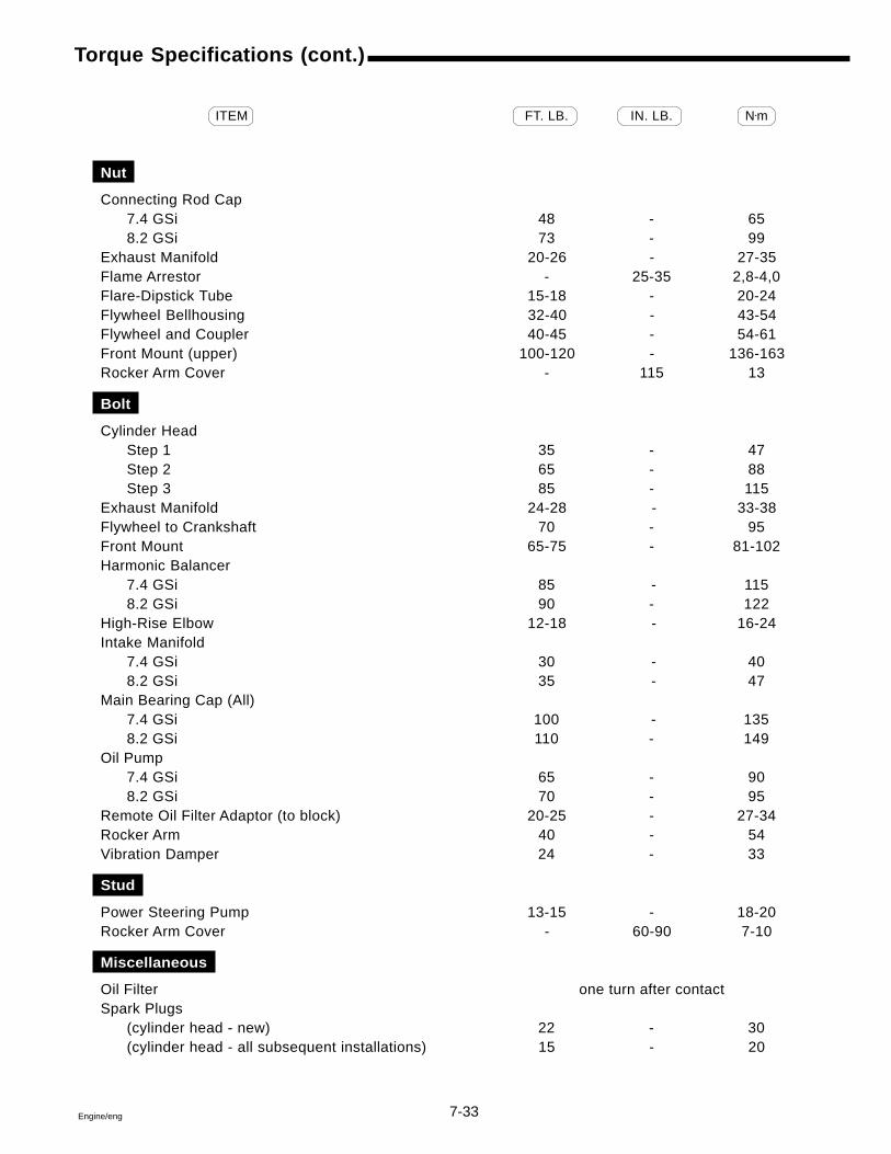
7-33Engine/eng
Torque Specifications (cont.)
ITEM FT. LB. IN. LB. N•m
Nut
Connecting Rod Cap7.4 GSi 48 - 658.2 GSi 73 - 99
Exhaust Manifold 20-26 - 27-35Flame Arrestor - 25-35 2,8-4,0Flare-Dipstick Tube 15-18 - 20-24Flywheel Bellhousing 32-40 - 43-54Flywheel and Coupler 40-45 - 54-61Front Mount (upper) 100-120 - 136-163Rocker Arm Cover - 115 13
Bolt
Cylinder HeadStep 1 35 - 47Step 2 65 - 88Step 3 85 - 115
Exhaust Manifold 24-28 - 33-38Flywheel to Crankshaft 70 - 95Front Mount 65-75 - 81-102Harmonic Balancer
7.4 GSi 85 - 1158.2 GSi 90 - 122
High-Rise Elbow 12-18 - 16-24Intake Manifold
7.4 GSi 30 - 408.2 GSi 35 - 47
Main Bearing Cap (All)7.4 GSi 100 - 1358.2 GSi 110 - 149
Oil Pump7.4 GSi 65 - 908.2 GSi 70 - 95
Remote Oil Filter Adaptor (to block) 20-25 - 27-34Rocker Arm 40 - 54Vibration Damper 24 - 33
Stud
Power Steering Pump 13-15 - 18-20Rocker Arm Cover - 60-90 7-10
Miscellaneous
Oil Filter one turn after contactSpark Plugs
(cylinder head - new) 22 - 30(cylinder head - all subsequent installations) 15 - 20

7-34 Engine/eng
8-1Engine/eng
Section 8Steering System
Table of Contents
8
Mechanical (Nonpower) Steering System ........................................ 8-3Cable Installation............................................................................. 8-3Cable Removal ................................................................................ 8-3Description ...................................................................................... 8-3Lubrication ....................................................................................... 8-4Sealants, Lubricants and Adhesives ............................................. 8-2Special Tools ................................................................................... 8-2Steering Tube Replacement ........................................................... 8-4Trim Tab Adjustment ..................................................................... 8-17
Power Steering System...................................................................... 8-5Cable Installation........................................................................... 8-15Cable Installation Problems ......................................................... 8-23Checking Fluid Level .................................................................... 8-10Cylinder Installation ...................................................................... 8-14Cylinder Removal .......................................................................... 8-13Cylinder Servicing ......................................................................... 8-14Description ...................................................................................... 8-5Diagnosis Chart ............................................................................. 8-19External Leakage ........................................................................... 8-21Feedback To Helm ......................................................................... 8-24Hoses ............................................................................................. 8-16Hydraulic Fluid .............................................................................. 8-10Lubrication ..................................................................................... 8-16Pump Belt Adjustment .................................................................. 8-12Pump Installation ............................................................................ 8-9Pump Leakage ............................................................................... 8-22Pump Operation .............................................................................. 8-6Pump Pressure Test ...................................................................... 8-22Pump Removal ................................................................................ 8-9Purging Air From Steering System .............................................. 8-11Sealants, Lubricants and Adhesives ............................................. 8-2Special Tools ................................................................................... 8-2Specifications - Torque ................................................................. 8-25Steering Cylinder ........................................................................... 8-13Steering Without Power Assist ...................................................... 8-8System Diagnosis ......................................................................... 8-16System Operation ........................................................................... 8-7Tie Bar Adjustment - Twin Engine Installations .......................... 8-18Trim Tab Adjustment ..................................................................... 8-17
8-2 Engine/eng
Special Tools
Rod Holder 3854367-4Pump Pulley Installer 9995444-8Pump Pulley Remover 9995443-0
Kent-Moore Special Tools
Pressure Gauge J-5176-EThermometer J-5421
Safety Warnings
Before working on any part of the steering system, read the Safetysection at the end of this manual.
When replacement parts are required, use genuine Volvo Penta orparts with equivalent characteristics including type, strength andmaterial. Failure to do so may result in product malfunction andpossible injury to the operator and/or passengers.
When working on an engine that is running or being cranked, useextreme care to avoid getting hands, fingers or clothing caught inthe alternator, power steering supply pump and circulating pumpbelts, pulleys and other moving parts.
Sealants, Lubricants and Adhesives
Cleaning SolventVolvo Penta GreaseVolvo Penta Power Trim/Tilt & Steering FluidGM Power Steering FluidVolvo Penta Thread Sealing AgentDexron, or Dexron IILoctite Primer
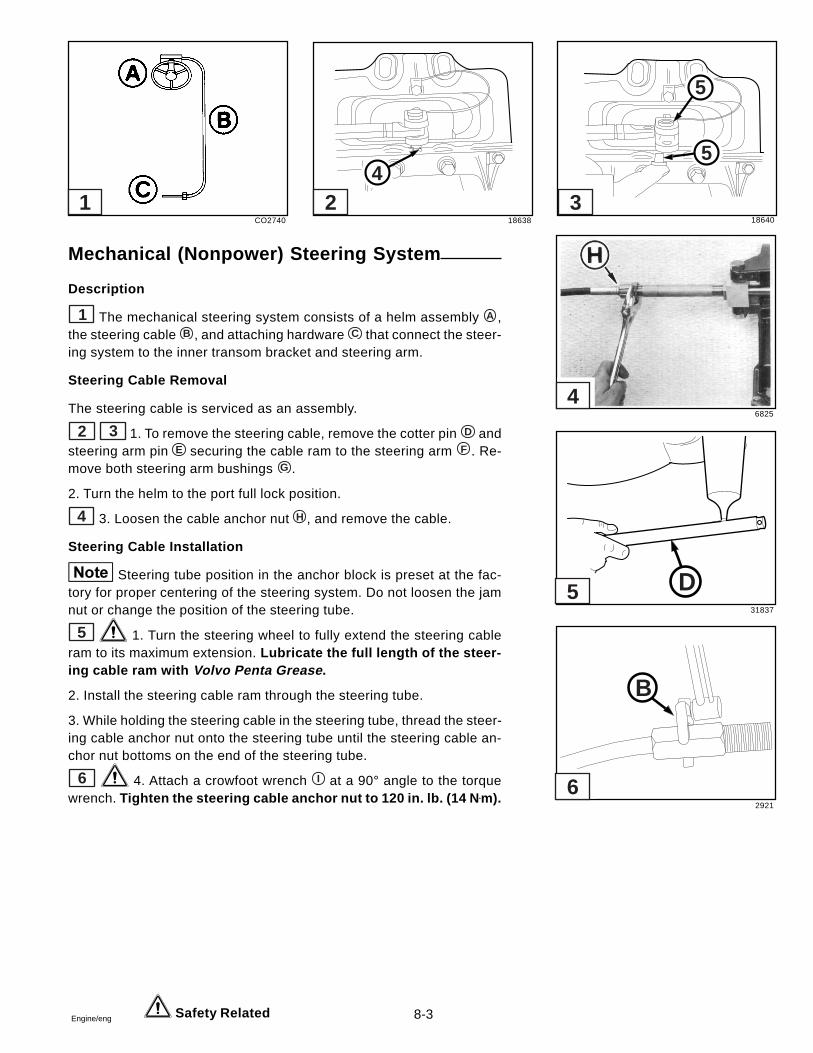
8-3Engine/eng
Mechanical (Nonpower) Steering System
Description
1 The mechanical steering system consists of a helm assembly A ,the steering cable B , and attaching hardware C that connect the steer-ing system to the inner transom bracket and steering arm.
Steering Cable Removal
The steering cable is serviced as an assembly.
2 3 1. To remove the steering cable, remove the cotter pin D andsteering arm pin E securing the cable ram to the steering arm F . Re-move both steering arm bushings G .
2. Turn the helm to the port full lock position.
4 3. Loosen the cable anchor nut H , and remove the cable.
Steering Cable Installation
Steering tube position in the anchor block is preset at the fac-tory for proper centering of the steering system. Do not loosen the jamnut or change the position of the steering tube.
5 1. Turn the steering wheel to fully extend the steering cableram to its maximum extension. Lubricate the full length of the steer-ing cable ram with Volvo Penta Grease .
2. Install the steering cable ram through the steering tube.
3. While holding the steering cable in the steering tube, thread the steer-ing cable anchor nut onto the steering tube until the steering cable an-chor nut bottoms on the end of the steering tube.
6 4. Attach a crowfoot wrench I at a 90° angle to the torquewrench. Tighten the steering cable anchor nut to 120 in. lb. (14 N •m).
Safety Related
CO2740 18638 18640
6825
31837
2921
4
5
5
D
B
1 2 3
6
5
4

8-4 Engine/eng Safety Related
5. Insert bushings into steering arm. Install the steering arm pin throughthe top hole in the steering arm and through the hole of the steeringcable ram.
6. Install the cotter pin through the steering arm pin and secureby spreading the ends of the cotter pin.
7. Turn the steering wheel to fully extend and retract the steering cableram. The steering arm should move from stop to stop as the steeringram moves from fully retracted to fully extended. Steering arm mustnot contact inside of transom cutout in either direction. Check for equalclearance of steering arm. Center the steering wheel and check cen-tering of steering arm. Readjust as necessary.
Steering System Lubrication
1 Lubricate the steering ram with Volvo Penta Grease ev-ery 50 hours or 60 days, which ever comes first.
Due to local conditions, it may be necessary to lubricate yoursteering ram at more frequent intervals.
Steering Tube Replacement
1. Loosen the jam nut and screw the steering tube out of the anchorblock. Remove the jam nut from the steering tube.
2 2. Screw the jam nut A all the way onto a new steering tube.
2 3. Measure 3-1/4 in. (8,26 cm) B in from the end of the steeringtube. Clean the following 1-1/4 in. (3,18 cm) of thread C with LoctitePrimer and allow to air dry. Apply Volvo Penta Thread Sealing Agent tothe 1-1/4 in. (3,18 cm) thread area C .
3 4. Screw the anchor block onto the steering tube until the block is3-5/32 in. (8,02 cm) D from the end. This dimension positions the steer-ing tube for accurate centering of the steering system.
5. Screw the jam nut up against the anchor block and tighten to 35-40ft. lb. (47-54 N•m). Do not disturb the anchor block position while tight-ening the nut.
4 5 6. If the anchor block was removed from the transomplate, apply a small mount of Volvo Penta Grease to both bushings.Install the block with the original screws. Tighten both to 40-45 ft. lb.(54-61 N•m). Secure screws with two cotter pins.
Filling the bushing pockets with grease can cause the screwsto hydraulically lock and break the transom plate when tightened.
3253
DR1726
DR1727
8012
8011
5
4
3
2
1
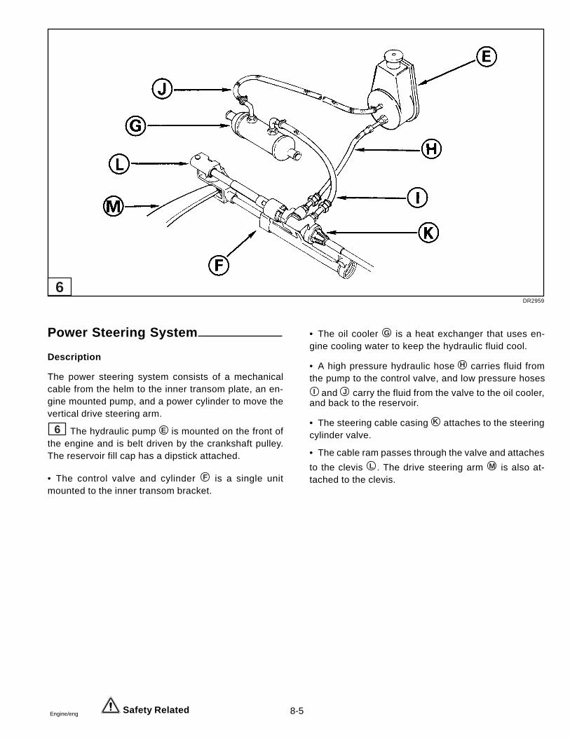
8-5Engine/eng Safety Related
Power Steering System
Description
The power steering system consists of a mechanicalcable from the helm to the inner transom plate, an en-gine mounted pump, and a power cylinder to move thevertical drive steering arm.
6 The hydraulic pump E is mounted on the front ofthe engine and is belt driven by the crankshaft pulley.The reservoir fill cap has a dipstick attached.
• The control valve and cylinder F is a single unitmounted to the inner transom bracket.
• The oil cooler G is a heat exchanger that uses en-gine cooling water to keep the hydraulic fluid cool.
• A high pressure hydraulic hose H carries fluid fromthe pump to the control valve, and low pressure hosesI and J carry the fluid from the valve to the oil cooler,
and back to the reservoir.
• The steering cable casing K attaches to the steeringcylinder valve.
• The cable ram passes through the valve and attaches
to the clevis L . The drive steering arm M is also at-tached to the clevis.
DR2959
6
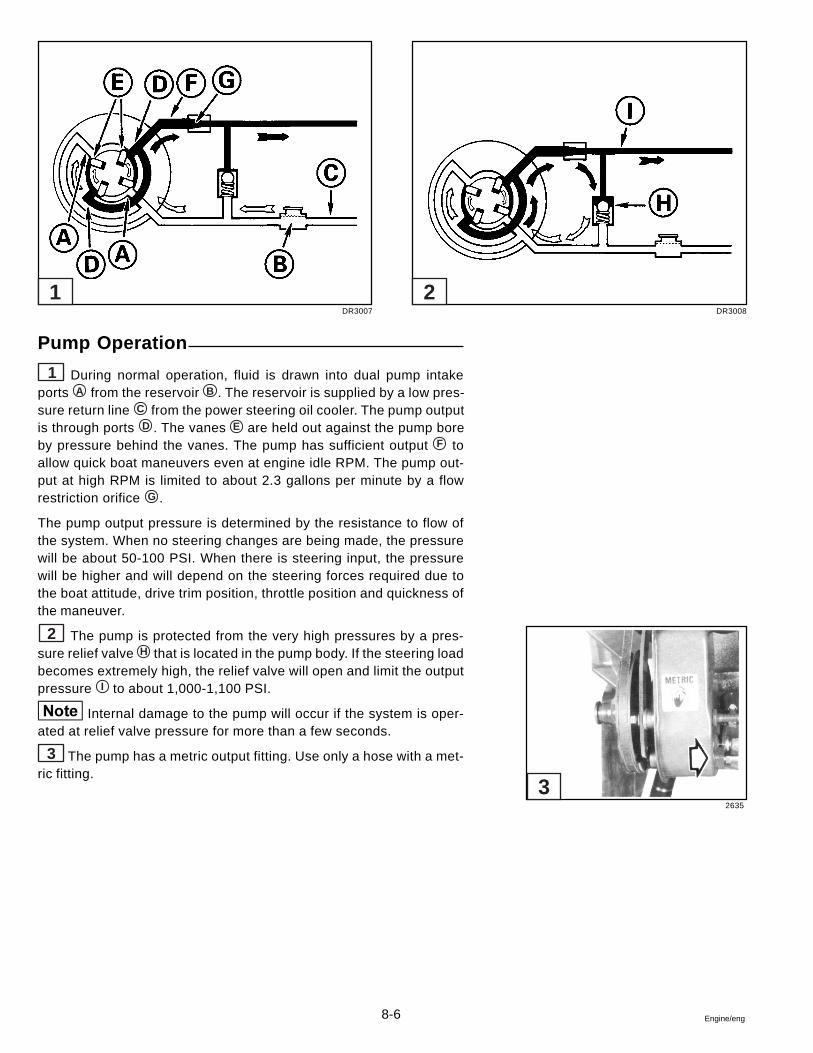
8-6 Engine/eng
Pump Operation
1 During normal operation, fluid is drawn into dual pump intakeports A from the reservoir B . The reservoir is supplied by a low pres-sure return line C from the power steering oil cooler. The pump outputis through ports D . The vanes E are held out against the pump boreby pressure behind the vanes. The pump has sufficient output F toallow quick boat maneuvers even at engine idle RPM. The pump out-put at high RPM is limited to about 2.3 gallons per minute by a flowrestriction orifice G .
The pump output pressure is determined by the resistance to flow ofthe system. When no steering changes are being made, the pressurewill be about 50-100 PSI. When there is steering input, the pressurewill be higher and will depend on the steering forces required due tothe boat attitude, drive trim position, throttle position and quickness ofthe maneuver.
2 The pump is protected from the very high pressures by a pres-sure relief valve H that is located in the pump body. If the steering loadbecomes extremely high, the relief valve will open and limit the outputpressure I to about 1,000-1,100 PSI.
Internal damage to the pump will occur if the system is oper-ated at relief valve pressure for more than a few seconds.
3 The pump has a metric output fitting. Use only a hose with a met-ric fitting.
DR3007
2635
DR3008
1 2
3
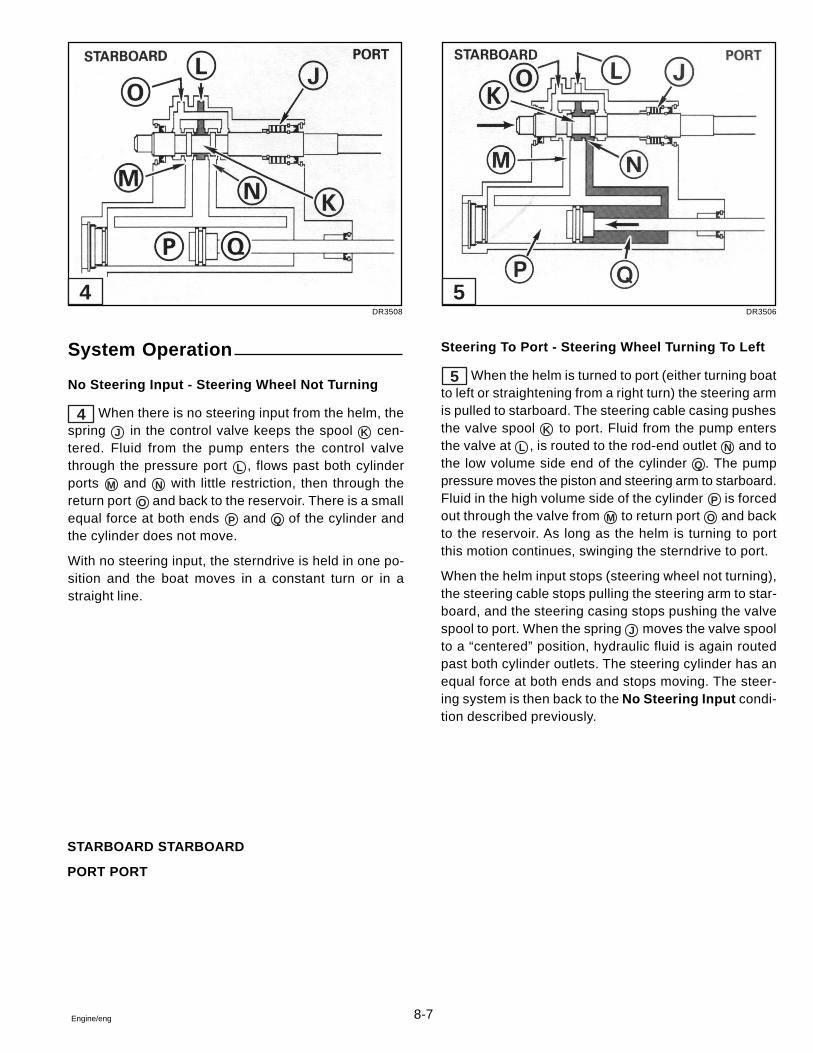
8-7Engine/eng
System Operation
No Steering Input - Steering Wheel Not Turning
4 When there is no steering input from the helm, thespring J in the control valve keeps the spool K cen-tered. Fluid from the pump enters the control valvethrough the pressure port L , flows past both cylinderports M and N with little restriction, then through thereturn port O and back to the reservoir. There is a smallequal force at both ends P and Q of the cylinder andthe cylinder does not move.
With no steering input, the sterndrive is held in one po-sition and the boat moves in a constant turn or in astraight line.
Steering To Port - Steering Wheel Turning To Left
5 When the helm is turned to port (either turning boatto left or straightening from a right turn) the steering armis pulled to starboard. The steering cable casing pushesthe valve spool K to port. Fluid from the pump entersthe valve at L , is routed to the rod-end outlet N and tothe low volume side end of the cylinder Q . The pumppressure moves the piston and steering arm to starboard.Fluid in the high volume side of the cylinder P is forcedout through the valve from M to return port O and backto the reservoir. As long as the helm is turning to portthis motion continues, swinging the sterndrive to port.
When the helm input stops (steering wheel not turning),the steering cable stops pulling the steering arm to star-board, and the steering casing stops pushing the valvespool to port. When the spring J moves the valve spoolto a “centered” position, hydraulic fluid is again routedpast both cylinder outlets. The steering cylinder has anequal force at both ends and stops moving. The steer-ing system is then back to the No Steering Input condi-tion described previously.
STARBOARD STARBOARD
PORT PORT
DR3508 DR3506
4 5
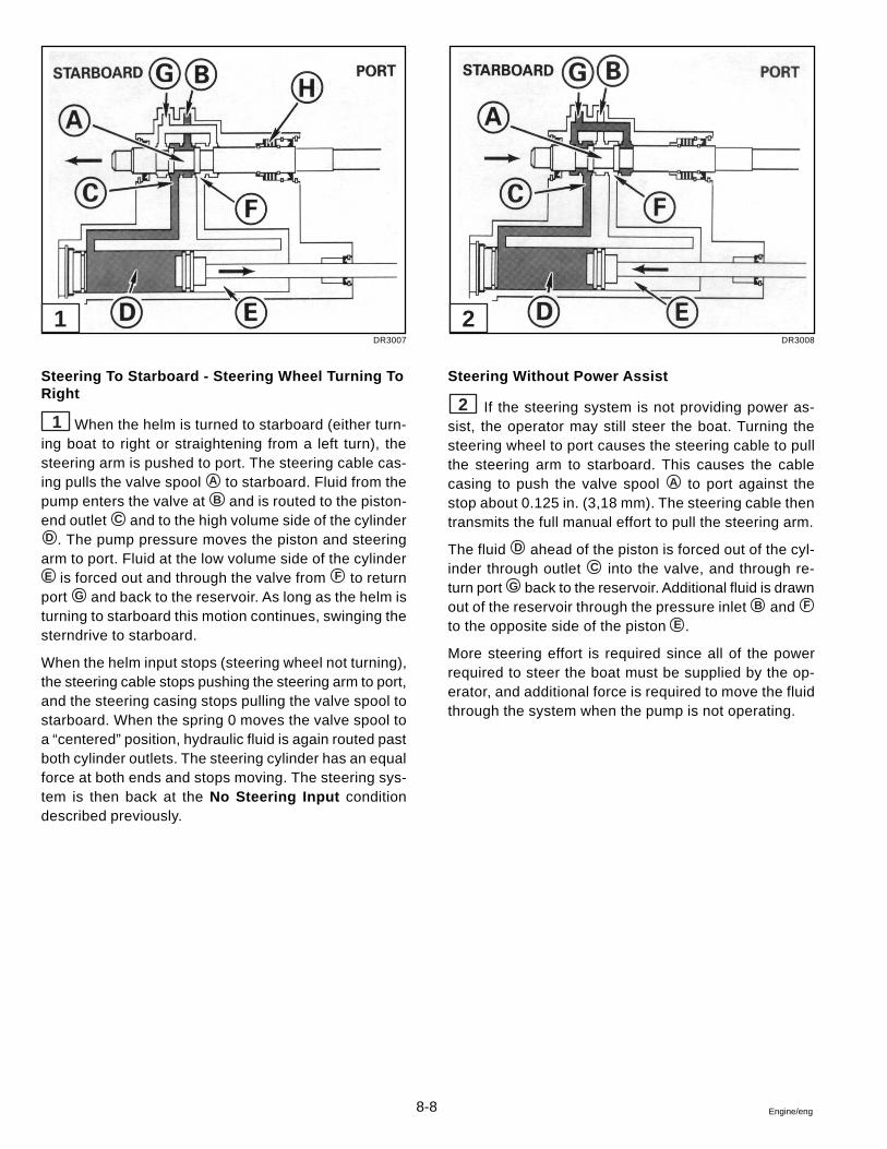
8-8 Engine/eng
Steering To Starboard - Steering Wheel Turning ToRight
1 When the helm is turned to starboard (either turn-ing boat to right or straightening from a left turn), thesteering arm is pushed to port. The steering cable cas-ing pulls the valve spool A to starboard. Fluid from thepump enters the valve at B and is routed to the piston-end outlet C and to the high volume side of the cylinderD . The pump pressure moves the piston and steering
arm to port. Fluid at the low volume side of the cylinderE is forced out and through the valve from F to returnport G and back to the reservoir. As long as the helm isturning to starboard this motion continues, swinging thesterndrive to starboard.
When the helm input stops (steering wheel not turning),the steering cable stops pushing the steering arm to port,and the steering casing stops pulling the valve spool tostarboard. When the spring 0 moves the valve spool toa “centered” position, hydraulic fluid is again routed pastboth cylinder outlets. The steering cylinder has an equalforce at both ends and stops moving. The steering sys-tem is then back at the No Steering Input conditiondescribed previously.
Steering Without Power Assist
2 If the steering system is not providing power as-sist, the operator may still steer the boat. Turning thesteering wheel to port causes the steering cable to pullthe steering arm to starboard. This causes the cablecasing to push the valve spool A to port against thestop about 0.125 in. (3,18 mm). The steering cable thentransmits the full manual effort to pull the steering arm.
The fluid D ahead of the piston is forced out of the cyl-inder through outlet C into the valve, and through re-turn port G back to the reservoir. Additional fluid is drawnout of the reservoir through the pressure inlet B and F
to the opposite side of the piston E .
More steering effort is required since all of the powerrequired to steer the boat must be supplied by the op-erator, and additional force is required to move the fluidthrough the system when the pump is not operating.
DR3007 DR3008
1 2
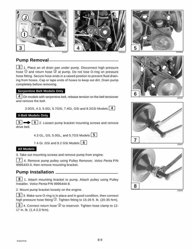
8-9Engine/eng
Pump Removal
3 1. Place an oil drain pan under pump. Disconnect high pressurehose I and return hose J at pump. Do not lose O-ring on pressurehose fitting. Secure hose ends in a raised position to prevent fluid drain-ing from hoses. Cap or tape ends of hoses to keep out dirt. Drain pumpcompletely before removing.
Serpentine Belt Models Only
4 On models with serpentine belt, release tension on the belt tensionerand remove the belt.
3.0GS, 4.3, 5.0Gi, 5.7GSi, 7.4Gi, GSi and 8.2GSi Models 4
V-Belt Models Only
5 6 2. Loosen pump bracket mounting screws and removedrive belt.
4.3 GL, GS, 5.0GL, and 5.7GS Models 5
7.4 Gi, GSi and 8.2 GSi Models 6
All Models
3. Take out mounting screws and remove pump from engine.
7 4. Remove pump pulley using Pulley Remover, Volvo Penta P/N9995443-0, then remove mounting bracket.
Pump Installation
8 1. Attach mounting bracket to pump. Attach pulley using PulleyInstaller, Volvo Penta P/N 9995444-8.
2. Mount pump bracket loosely on the engine.
3 3. Make sure O-ring is in place and in good condition, then connecthigh pressure hose fitting I . Tighten fitting to 15-26 ft. lb. (20-35 N•m).
3 4. Connect return hose J to reservoir. Tighten hose clamp to 12-17 in. lb. (1,4-2,0 N•m).
20497 23916A 20496A
20510
20847
20846
8
7
6
543
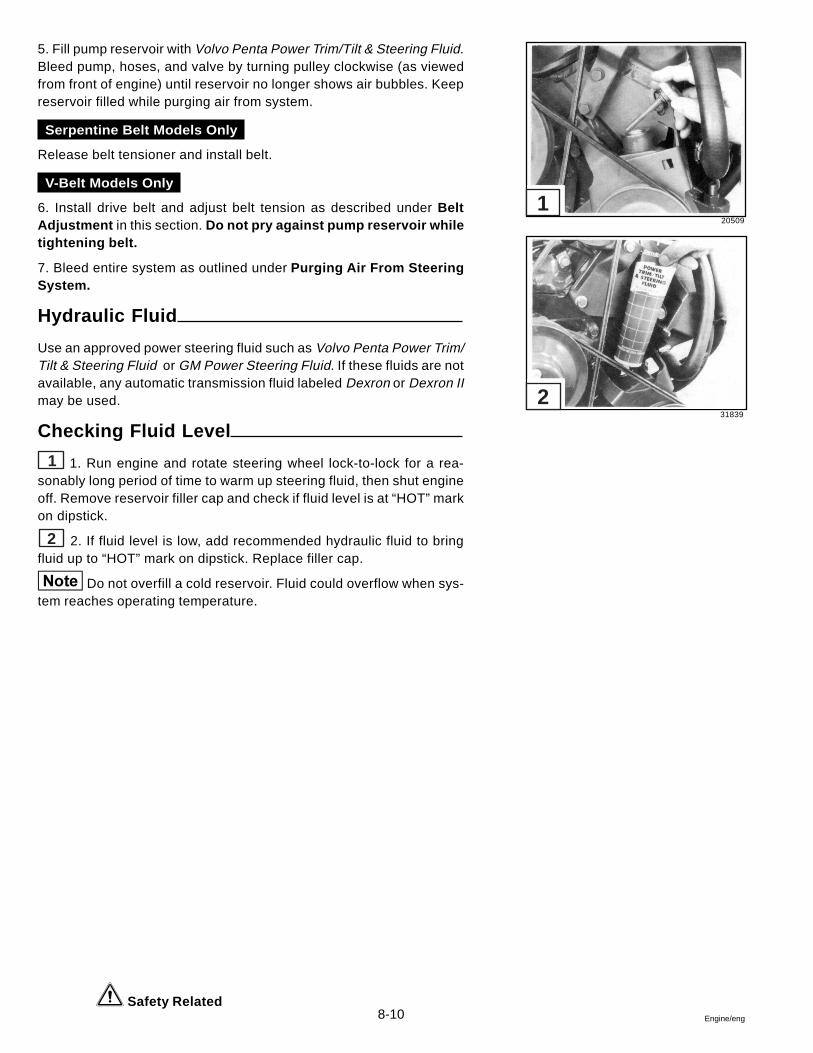
8-10 Engine/eng
Safety Related
5. Fill pump reservoir with Volvo Penta Power Trim/Tilt & Steering Fluid.Bleed pump, hoses, and valve by turning pulley clockwise (as viewedfrom front of engine) until reservoir no longer shows air bubbles. Keepreservoir filled while purging air from system.
Serpentine Belt Models Only
Release belt tensioner and install belt.
V-Belt Models Only
6. Install drive belt and adjust belt tension as described under BeltAdjustment in this section. Do not pry against pump reservoir whiletightening belt.
7. Bleed entire system as outlined under Purging Air From SteeringSystem.
Hydraulic Fluid
Use an approved power steering fluid such as Volvo Penta Power Trim/Tilt & Steering Fluid or GM Power Steering Fluid. If these fluids are notavailable, any automatic transmission fluid labeled Dexron or Dexron IImay be used.
Checking Fluid Level
1 1. Run engine and rotate steering wheel lock-to-lock for a rea-sonably long period of time to warm up steering fluid, then shut engineoff. Remove reservoir filler cap and check if fluid level is at “HOT” markon dipstick.
2 2. If fluid level is low, add recommended hydraulic fluid to bringfluid up to “HOT” mark on dipstick. Replace filler cap.
Do not overfill a cold reservoir. Fluid could overflow when sys-tem reaches operating temperature.
20509
31839
1
2
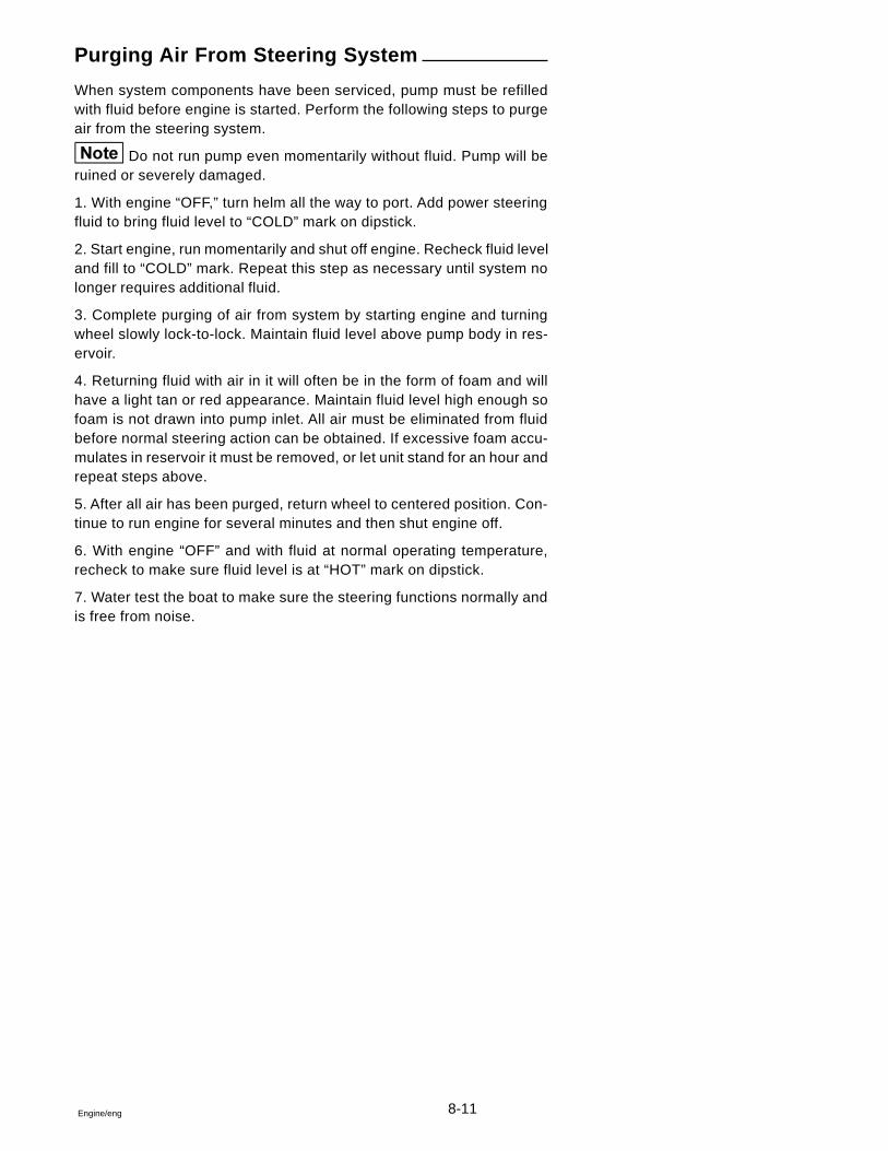
8-11Engine/eng
Purging Air From Steering System
When system components have been serviced, pump must be refilledwith fluid before engine is started. Perform the following steps to purgeair from the steering system.
Do not run pump even momentarily without fluid. Pump will beruined or severely damaged.
1. With engine “OFF,” turn helm all the way to port. Add power steeringfluid to bring fluid level to “COLD” mark on dipstick.
2. Start engine, run momentarily and shut off engine. Recheck fluid leveland fill to “COLD” mark. Repeat this step as necessary until system nolonger requires additional fluid.
3. Complete purging of air from system by starting engine and turningwheel slowly lock-to-lock. Maintain fluid level above pump body in res-ervoir.
4. Returning fluid with air in it will often be in the form of foam and willhave a light tan or red appearance. Maintain fluid level high enough sofoam is not drawn into pump inlet. All air must be eliminated from fluidbefore normal steering action can be obtained. If excessive foam accu-mulates in reservoir it must be removed, or let unit stand for an hour andrepeat steps above.
5. After all air has been purged, return wheel to centered position. Con-tinue to run engine for several minutes and then shut engine off.
6. With engine “OFF” and with fluid at normal operating temperature,recheck to make sure fluid level is at “HOT” mark on dipstick.
7. Water test the boat to make sure the steering functions normally andis free from noise.
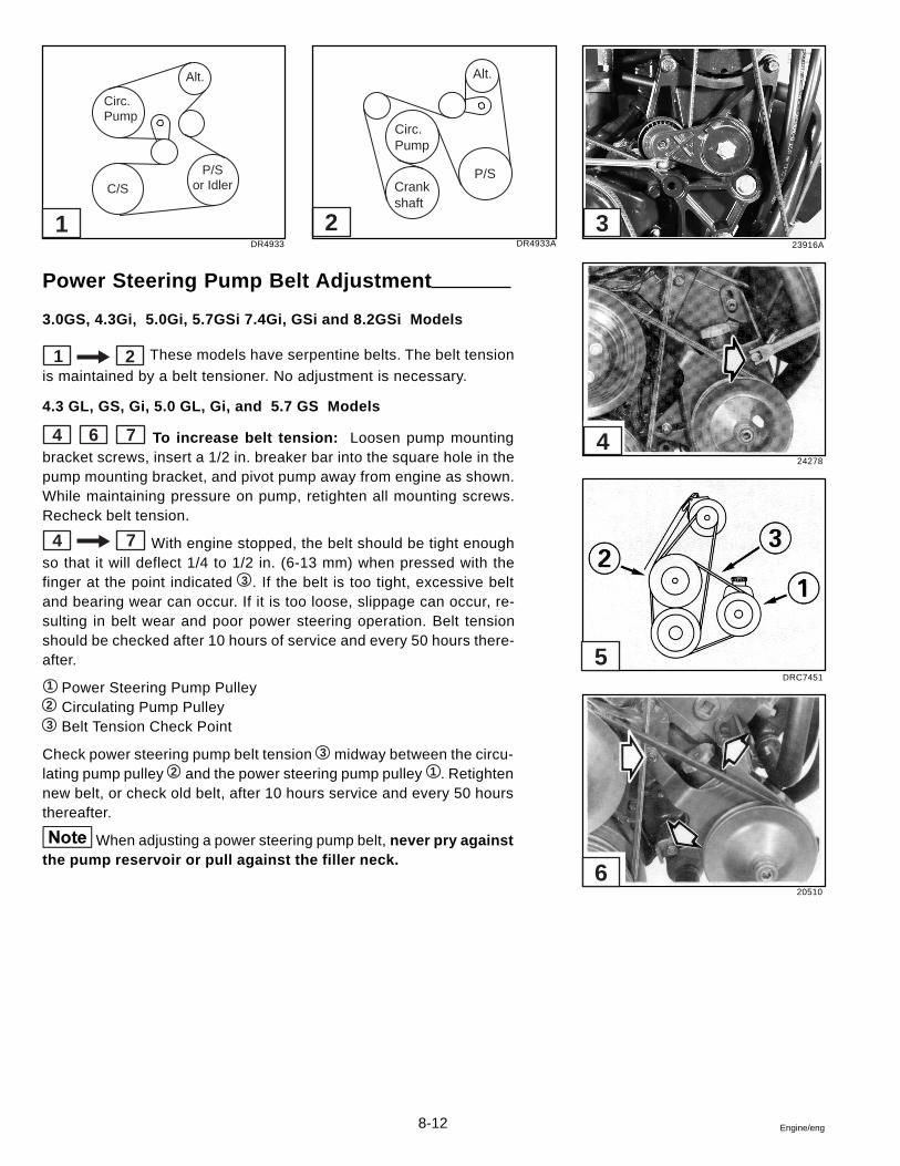
8-12 Engine/eng
Power Steering Pump Belt Adjustment
3.0GS, 4.3Gi, 5.0Gi, 5.7GSi 7.4Gi, GSi and 8.2GSi Models
1 2 These models have serpentine belts. The belt tension
is maintained by a belt tensioner. No adjustment is necessary.
4.3 GL, GS, Gi, 5.0 GL, Gi, and 5.7 GS Models
4 6 7 To increase belt tension: Loosen pump mountingbracket screws, insert a 1/2 in. breaker bar into the square hole in thepump mounting bracket, and pivot pump away from engine as shown.While maintaining pressure on pump, retighten all mounting screws.Recheck belt tension.
4 7 With engine stopped, the belt should be tight enoughso that it will deflect 1/4 to 1/2 in. (6-13 mm) when pressed with thefinger at the point indicated 3 . If the belt is too tight, excessive beltand bearing wear can occur. If it is too loose, slippage can occur, re-sulting in belt wear and poor power steering operation. Belt tensionshould be checked after 10 hours of service and every 50 hours there-after.
1 Power Steering Pump Pulley2 Circulating Pump Pulley3 Belt Tension Check Point
Check power steering pump belt tension 3 midway between the circu-lating pump pulley 2 and the power steering pump pulley 1 . Retightennew belt, or check old belt, after 10 hours service and every 50 hoursthereafter.
When adjusting a power steering pump belt, never pry againstthe pump reservoir or pull against the filler neck.
23916ADR4933
24278
DRC7451
20510
Alt.
P/Sor Idler
Circ.Pump
C/S
5
4
321
Alt.
P/S
Circ.Pump
Crankshaft
DR4933A
6
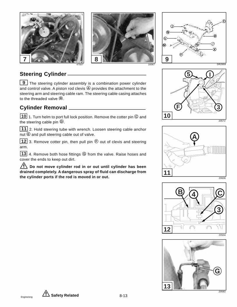
8-13Engine/eng
Steering Cylinder
9 The steering cylinder assembly is a combination power cylinderand control valve. A piston rod clevis A provides the attachment to thesteering arm and steering cable ram. The steering cable casing attachesto the threaded valve B .
Cylinder Removal
10 1. Turn helm to port full lock position. Remove the cotter pin C andthe steering cable pin D .
11 2. Hold steering tube with wrench. Loosen steering cable anchornut E and pull steering cable out of valve.
12 3. Remove cotter pin, then pull pin F out of clevis and steeringarm.
13 4. Remove both hose fittings G from the valve. Raise hoses andcover the ends to keep out dirt.
Do not move cylinder rod in or out until cylinder has beendrained completely. A dangerous spray of fluid can discharge fromthe cylinder ports if the rod is moved in or out.
Safety Related
47507 16067 DR2959
20572
20606
20504
20583
5 I
F 3
A
B
3
4 C
13
12
11
10
987
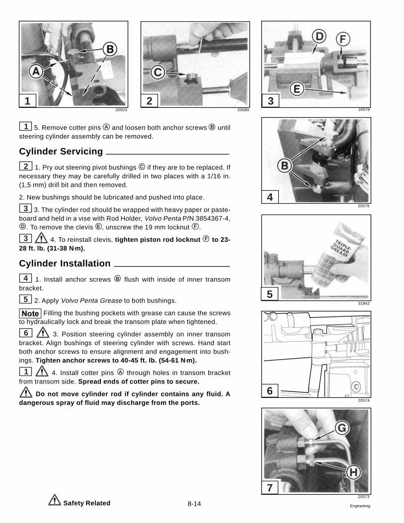
8-14 Engine/eng
1 5. Remove cotter pins A and loosen both anchor screws B untilsteering cylinder assembly can be removed.
Cylinder Servicing
2 1. Pry out steering pivot bushings C if they are to be replaced. Ifnecessary they may be carefully drilled in two places with a 1/16 in.(1,5 mm) drill bit and then removed.
2. New bushings should be lubricated and pushed into place.
3 3. The cylinder rod should be wrapped with heavy paper or paste-board and held in a vise with Rod Holder, Volvo Penta P/N 3854367-4,D . To remove the clevis E , unscrew the 19 mm locknut F .
3 4. To reinstall clevis, tighten piston rod locknut F to 23-28 ft. lb. (31-38 N •m).
Cylinder Installation
4 1. Install anchor screws B flush with inside of inner transombracket.
5 2. Apply Volvo Penta Grease to both bushings.
Filling the bushing pockets with grease can cause the screwsto hydraulically lock and break the transom plate when tightened.
6 3. Position steering cylinder assembly on inner transombracket. Align bushings of steering cylinder with screws. Hand startboth anchor screws to ensure alignment and engagement into bush-ings. Tighten anchor screws to 40-45 ft. lb. (54-61 N •m).
1 4. Install cotter pins A through holes in transom bracketfrom transom side. Spread ends of cotter pins to secure.
Do not move cylinder rod if cylinder contains any fluid. Adangerous spray of fluid may discharge from the ports.
Safety Related
20503 20580 20579
20576
31842
20574
20573
7
6
5
4
321
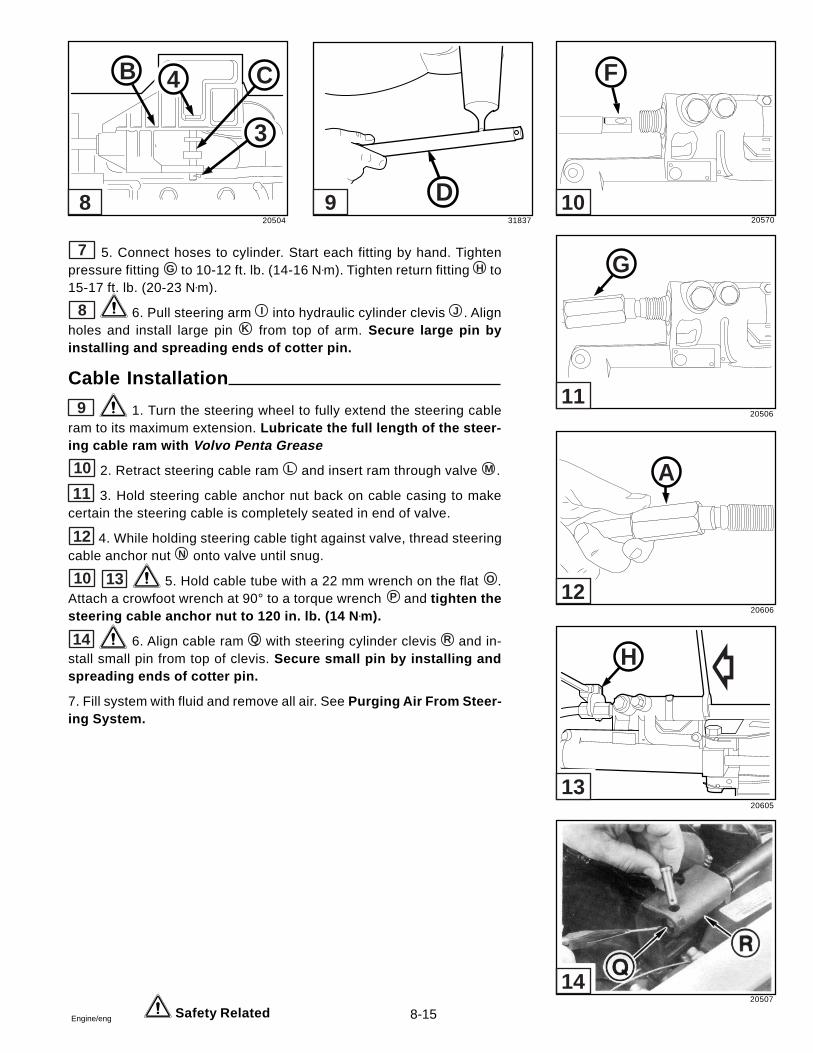
8-15Engine/eng
7 5. Connect hoses to cylinder. Start each fitting by hand. Tightenpressure fitting G to 10-12 ft. lb. (14-16 N•m). Tighten return fitting H to15-17 ft. lb. (20-23 N•m).
8 6. Pull steering arm I into hydraulic cylinder clevis J . Alignholes and install large pin K from top of arm. Secure large pin byinstalling and spreading ends of cotter pin.
Cable Installation
9 1. Turn the steering wheel to fully extend the steering cableram to its maximum extension. Lubricate the full length of the steer-ing cable ram with Volvo Penta Grease
10 2. Retract steering cable ram L and insert ram through valve M .
11 3. Hold steering cable anchor nut back on cable casing to makecertain the steering cable is completely seated in end of valve.
12 4. While holding steering cable tight against valve, thread steeringcable anchor nut N onto valve until snug.
10 13 5. Hold cable tube with a 22 mm wrench on the flat O .Attach a crowfoot wrench at 90° to a torque wrench P and tighten thesteering cable anchor nut to 120 in. lb. (14 N •m).
14 6. Align cable ram Q with steering cylinder clevis R and in-stall small pin from top of clevis. Secure small pin by installing andspreading ends of cotter pin.
7. Fill system with fluid and remove all air. See Purging Air From Steer-ing System.
Safety Related
20504 31837 20570
20506
20606
20605
20507
B
3
4 C
D
F
G
A
H
14
13
12
11
1098
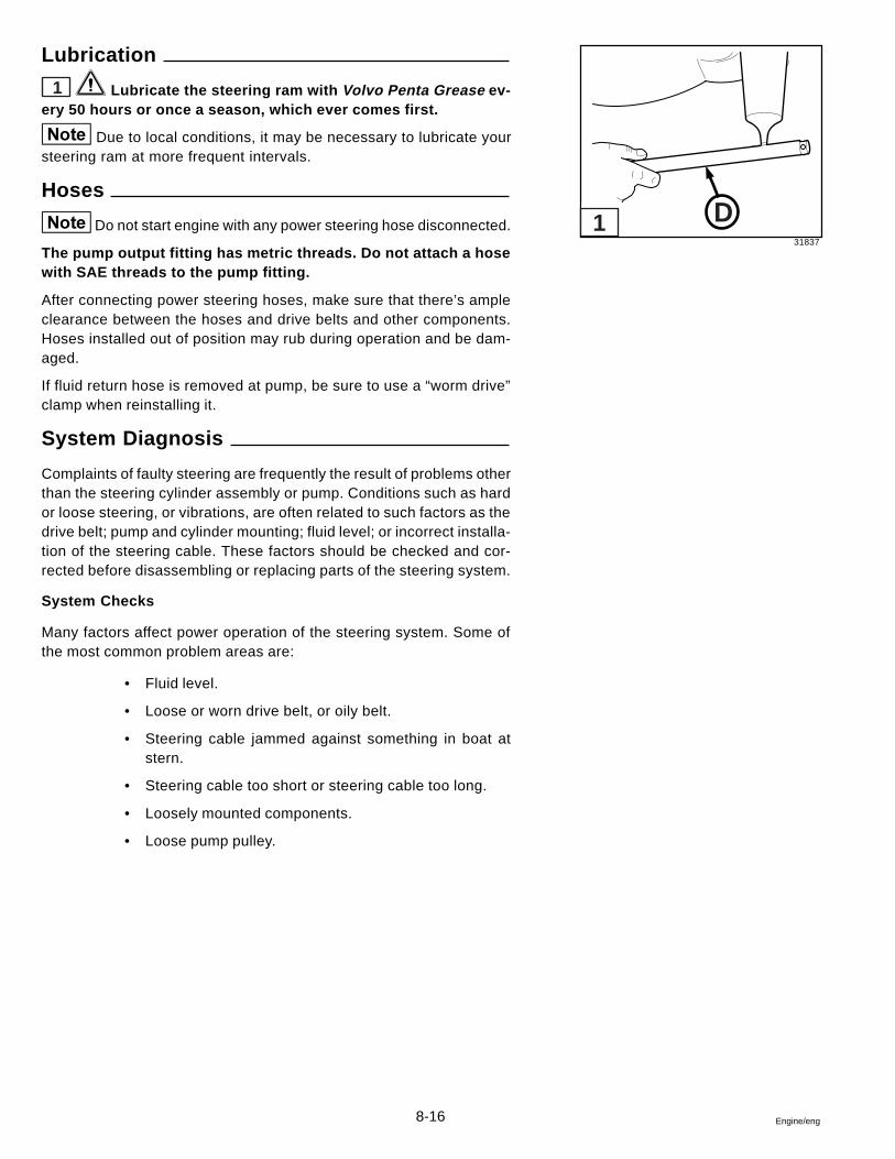
8-16 Engine/eng
Lubrication
1 Lubricate the steering ram with Volvo Penta Grease ev-ery 50 hours or once a season, which ever comes first.
Due to local conditions, it may be necessary to lubricate yoursteering ram at more frequent intervals.
Hoses
Do not start engine with any power steering hose disconnected.
The pump output fitting has metric threads. Do not attach a hosewith SAE threads to the pump fitting.
After connecting power steering hoses, make sure that there’s ampleclearance between the hoses and drive belts and other components.Hoses installed out of position may rub during operation and be dam-aged.
If fluid return hose is removed at pump, be sure to use a “worm drive”clamp when reinstalling it.
System Diagnosis
Complaints of faulty steering are frequently the result of problems otherthan the steering cylinder assembly or pump. Conditions such as hardor loose steering, or vibrations, are often related to such factors as thedrive belt; pump and cylinder mounting; fluid level; or incorrect installa-tion of the steering cable. These factors should be checked and cor-rected before disassembling or replacing parts of the steering system.
System Checks
Many factors affect power operation of the steering system. Some ofthe most common problem areas are:
• Fluid level.
• Loose or worn drive belt, or oily belt.
• Steering cable jammed against something in boat atstern.
• Steering cable too short or steering cable too long.
• Loosely mounted components.
• Loose pump pulley.
31837
D1
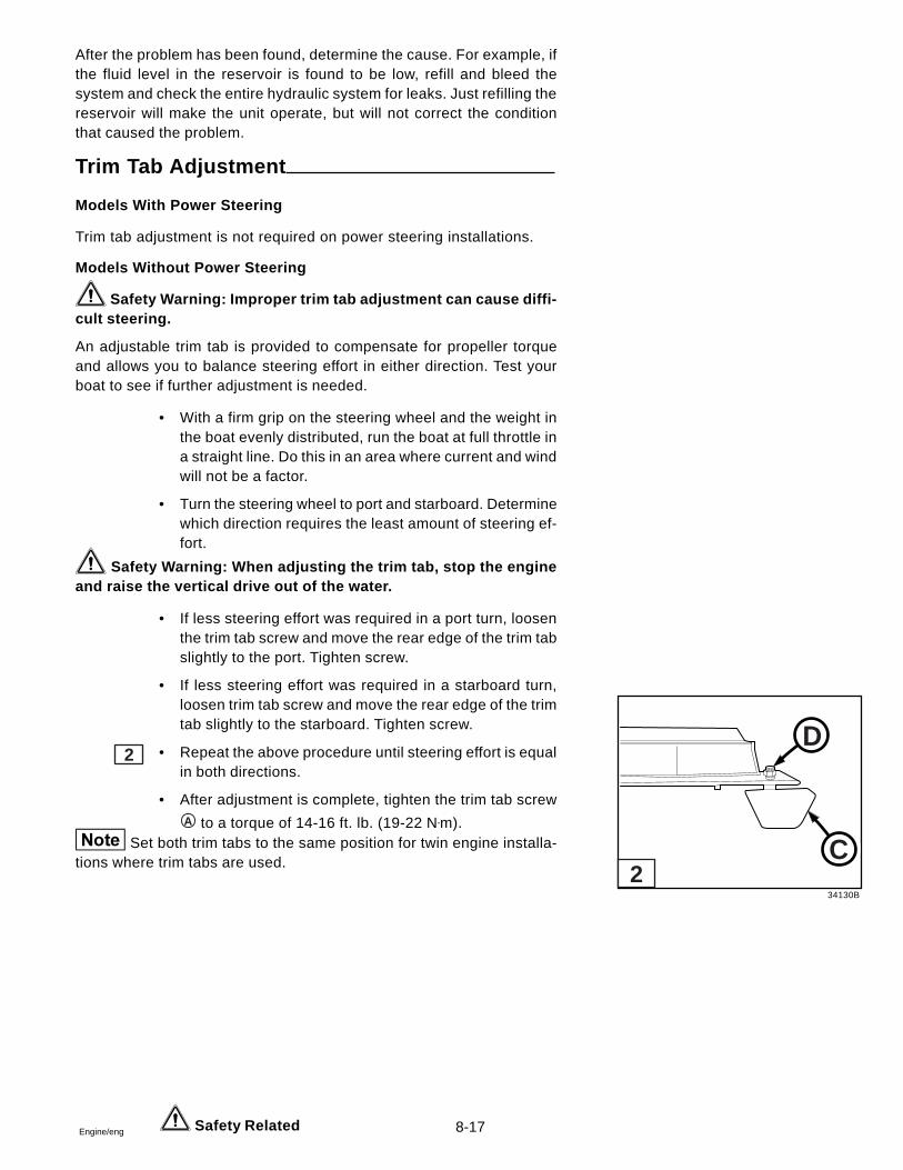
8-17Engine/eng
After the problem has been found, determine the cause. For example, ifthe fluid level in the reservoir is found to be low, refill and bleed thesystem and check the entire hydraulic system for leaks. Just refilling thereservoir will make the unit operate, but will not correct the conditionthat caused the problem.
Trim Tab Adjustment
Models With Power Steering
Trim tab adjustment is not required on power steering installations.
Models Without Power Steering
Safety Warning: Improper trim tab adjustment can cause diffi-cult steering.
An adjustable trim tab is provided to compensate for propeller torqueand allows you to balance steering effort in either direction. Test yourboat to see if further adjustment is needed.
• With a firm grip on the steering wheel and the weight inthe boat evenly distributed, run the boat at full throttle ina straight line. Do this in an area where current and windwill not be a factor.
• Turn the steering wheel to port and starboard. Determinewhich direction requires the least amount of steering ef-fort.
Safety Warning: When adjusting the trim tab, stop the engineand raise the vertical drive out of the water.
• If less steering effort was required in a port turn, loosenthe trim tab screw and move the rear edge of the trim tabslightly to the port. Tighten screw.
• If less steering effort was required in a starboard turn,loosen trim tab screw and move the rear edge of the trimtab slightly to the starboard. Tighten screw.
• Repeat the above procedure until steering effort is equalin both directions.
• After adjustment is complete, tighten the trim tab screwA to a torque of 14-16 ft. lb. (19-22 N•m).
Set both trim tabs to the same position for twin engine installa-tions where trim tabs are used.
2
Safety Related
34130B
D
C2
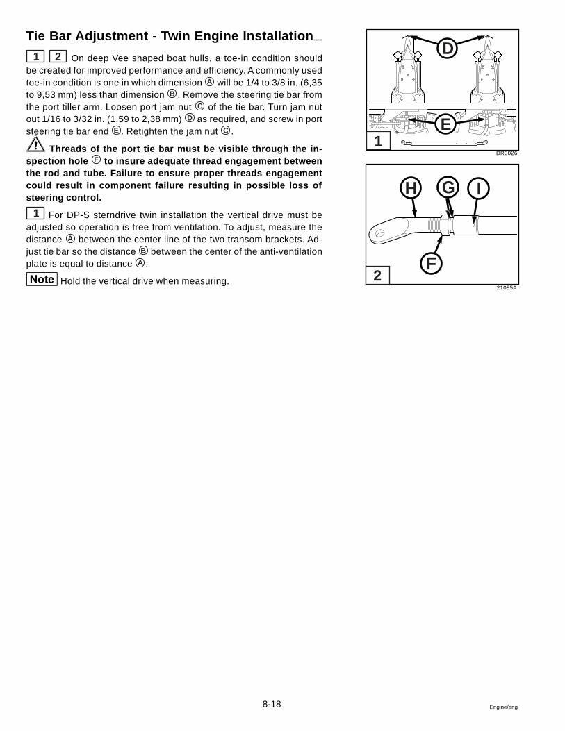
8-18 Engine/eng
Tie Bar Adjustment - Twin Engine Installation
1 2 On deep Vee shaped boat hulls, a toe-in condition shouldbe created for improved performance and efficiency. A commonly usedtoe-in condition is one in which dimension A will be 1/4 to 3/8 in. (6,35to 9,53 mm) less than dimension B . Remove the steering tie bar fromthe port tiller arm. Loosen port jam nut C of the tie bar. Turn jam nutout 1/16 to 3/32 in. (1,59 to 2,38 mm) D as required, and screw in portsteering tie bar end E . Retighten the jam nut C .
Threads of the port tie bar must be visible through the in-spection hole F to insure adequate thread engagement betweenthe rod and tube. Failure to ensure proper threads engagementcould result in component failure resulting in possible loss ofsteering control.
1 For DP-S sterndrive twin installation the vertical drive must beadjusted so operation is free from ventilation. To adjust, measure thedistance A between the center line of the two transom brackets. Ad-just tie bar so the distance B between the center of the anti-ventilationplate is equal to distance A .
Hold the vertical drive when measuring.
DR3026
21085A
D
E
H I
F
G
1
2
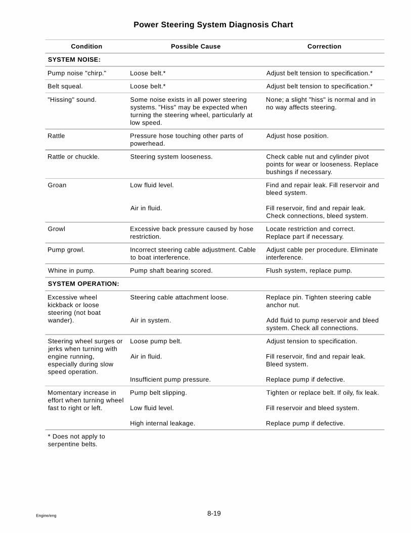
8-19Engine/eng
Power Steering System Diagnosis Chart
Condition Possible Cause Correction
SYSTEM NOISE:
Pump noise "chirp." Loose belt.* Adjust belt tension to specification.*
Belt squeal. Loose belt.* Adjust belt tension to specification.*
"Hissing" sound. Some noise exists in all power steeringsystems. "Hiss" may be expected whenturning the steering wheel, particularly atlow speed.
None; a slight "hiss" is normal and inno way affects steering.
Rattle Pressure hose touching other parts ofpowerhead.
Adjust hose position.
Rattle or chuckle. Steering system looseness. Check cable nut and cylinder pivotpoints for wear or looseness. Replacebushings if necessary.
Groan Low fluid level.
Air in fluid.
Find and repair leak. Fill reservoir andbleed system.
Fill reservoir, find and repair leak.Check connections, bleed system.
Growl Excessive back pressure caused by hoserestriction.
Locate restriction and correct.Replace part if necessary.
Pump growl. Incorrect steering cable adjustment. Cableto boat interference.
Adjust cable per procedure. Eliminateinterference.
Whine in pump. Pump shaft bearing scored. Flush system, replace pump.
SYSTEM OPERATION:
Excessive wheelkickback or loosesteering (not boatwander).
Steering cable attachment loose.
Air in system.
Replace pin. Tighten steering cableanchor nut.
Add fluid to pump reservoir and bleedsystem. Check all connections.
Steering wheel surges orjerks when turning withengine running,especially during slowspeed operation.
Loose pump belt.
Air in fluid.
Insufficient pump pressure.
Adjust tension to specification.
Fill reservoir, find and repair leak.Bleed system.
Replace pump if defective.
Momentary increase ineffort when turning wheelfast to right or left.
Pump belt slipping.
Low fluid level.
High internal leakage.
Tighten or replace belt. If oily, fix leak.
Fill reservoir and bleed system.
Replace pump if defective.
* Does not apply toserpentine belts.
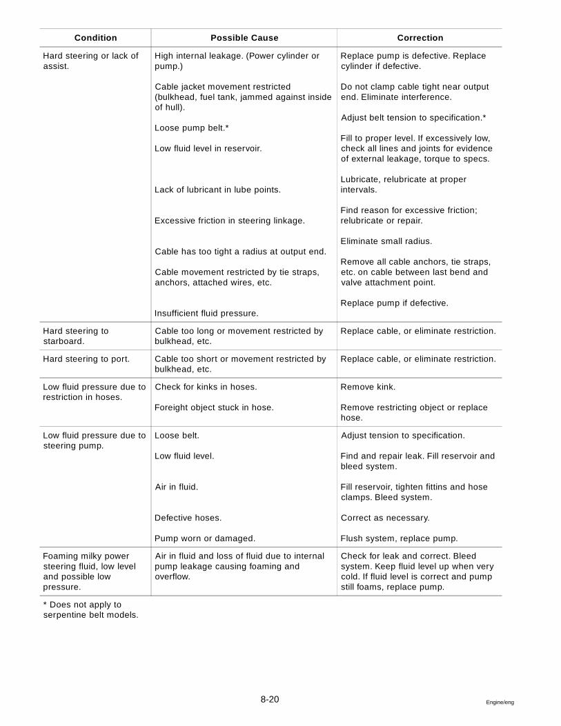
8-20 Engine/eng
Condition Possible Cause Correction
Hard steering or lack ofassist.
High internal leakage. (Power cylinder orpump.)
Cable jacket movement restricted(bulkhead, fuel tank, jammed against insideof hull).
Loose pump belt.*
Low fluid level in reservoir.
Lack of lubricant in lube points.
Excessive friction in steering linkage.
Cable has too tight a radius at output end.
Cable movement restricted by tie straps,anchors, attached wires, etc.
Insufficient fluid pressure.
Replace pump is defective. Replacecylinder if defective.
Do not clamp cable tight near outputend. Eliminate interference.
Adjust belt tension to specification.*
Fill to proper level. If excessively low,check all lines and joints for evidenceof external leakage, torque to specs.
Lubricate, relubricate at properintervals.
Find reason for excessive friction;relubricate or repair.
Eliminate small radius.
Remove all cable anchors, tie straps,etc. on cable between last bend andvalve attachment point.
Replace pump if defective.
Hard steering tostarboard.
Cable too long or movement restricted bybulkhead, etc.
Replace cable, or eliminate restriction.
Hard steering to port. Cable too short or movement restricted bybulkhead, etc.
Replace cable, or eliminate restriction.
Low fluid pressure due torestriction in hoses.
Check for kinks in hoses.
Foreight object stuck in hose.
Remove kink.
Remove restricting object or replacehose.
Low fluid pressure due tosteering pump.
Loose belt.
Low fluid level.
Air in fluid.
Defective hoses.
Pump worn or damaged.
Adjust tension to specification.
Find and repair leak. Fill reservoir andbleed system.
Fill reservoir, tighten fittins and hoseclamps. Bleed system.
Correct as necessary.
Flush system, replace pump.
Foaming milky powersteering fluid, low leveland possible lowpressure.
Air in fluid and loss of fluid due to internalpump leakage causing foaming andoverflow.
Check for leak and correct. Bleedsystem. Keep fluid level up when verycold. If fluid level is correct and pumpstill foams, replace pump.
* Does not apply toserpentine belt models.
8-21Engine/eng
External Leakage
General Procedure
1. Wipe suspected area dry.
2. Check for overfilled reservoir.
3. Check for fluid aeration and overflow.
4. Check hose connections - tighten if necessary.
5. Determine exact point of leakage.
6. When service is required, replace component.
Leakage Checks
Although some leaks are easily found, seepage type leaks may be dif-ficult to pinpoint. Locate seepage leaks as follows:
1. With the engine off, wipe the complete power steering system dry(pump, hoses, and connections).
2. Check the fluid level in the pump reservoir and adjust as directed.
3. Start the engine and turn the steering wheel from stop-to-stop severaltimes.
4. Find the exact area of leakage.
Easily Fixed Leaks
1. Loose clamp on pump return hose.
2. Loose pump or cylinder hose fitting. If fittings are not cross-threaded,tighten to correct torque. See Torque Specifications.
3. Damaged O-ring on pump pressure fitting. Replace O-ring.
4. External leakage of power cylinder. Replace power cylinder.
5. Leakage of fluid in cooling water. Replace oil cooler.
6. Damage or cracked hose. Replace hose.
If the return hose is removed, the clamp must be replaced with a wormdrive clamp. Replace leaky hoses.
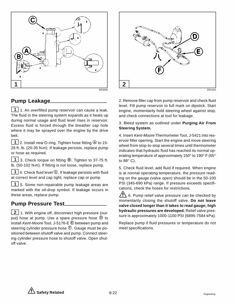
8-22 Engine/eng
Pump Leakage
1 1. An overfilled pump reservoir can cause a leak.The fluid in the steering system expands as it heats upduring normal usage and fluid level rises in reservoir.Excess fluid is forced through the breather cap holewhere it may be sprayed over the engine by the drivebelt.
1 2. Install new O-ring. Tighten hose fitting A to 15-26 ft. lb. (20-35 N•m). If leakage persists, replace pumpor hose as required.
1 3. Check torque on fitting B . Tighten to 37-75 ft.lb. (50-102 N•m). If fitting is not loose, replace pump.
1 4. Check fluid level C . If leakage persists with fluidat correct level and cap tight, replace cap or pump.
1 5. Some non-repairable pump leakage areas aremarked with the oil-drop symbol. If leakage occurs inthese areas, replace pump.
Pump Pressure Test
2 1. With engine off, disconnect high pressure (out-put) hose at pump. Use a spare pressure hose D toinstall Kent-Moore Tool, J-5176-E E between pump andsteering cylinder pressure hose F . Gauge must be po-sitioned between shutoff valve and pump. Connect steer-ing cylinder pressure hose to shutoff valve. Open shut-off valve.
2. Remove filler cap from pump reservoir and check fluidlevel. Fill pump reservoir to full mark on dipstick. Startengine, momentarily hold steering wheel against stop,and check connections at tool for leakage.
3. Bleed system as outlined under Purging Air FromSteering System.
4. Insert Kent-Moore Thermometer Tool, J-5421 into res-ervoir filler opening. Start the engine and move steeringwheel from stop-to-stop several times until thermometerindicates that hydraulic fluid has reached its normal op-erating temperature of approximately 150° to 190° F (65°to 88° C).
5. Check fluid level; add fluid if required. When engineis at normal operating temperature, the pressure read-ing on the gauge (valve open) should be in the 50-100PSI (345-690 kPa) range. If pressure exceeds specifi-cations, check the hoses for restrictions.
6. Pump relief valve pressure can be checked bymomentarily closing the shutoff valve. Do not leavevalve closed longer than it takes to read gauge; highhydraulic pressures are developed. Relief valve pres-sure is approximately 1000-1100 PSI (6895-7584 kPa).
Replace pump if fluid pressures or temperature do notmeet specifications.
Safety Related
DR3009 DR1443
1 2
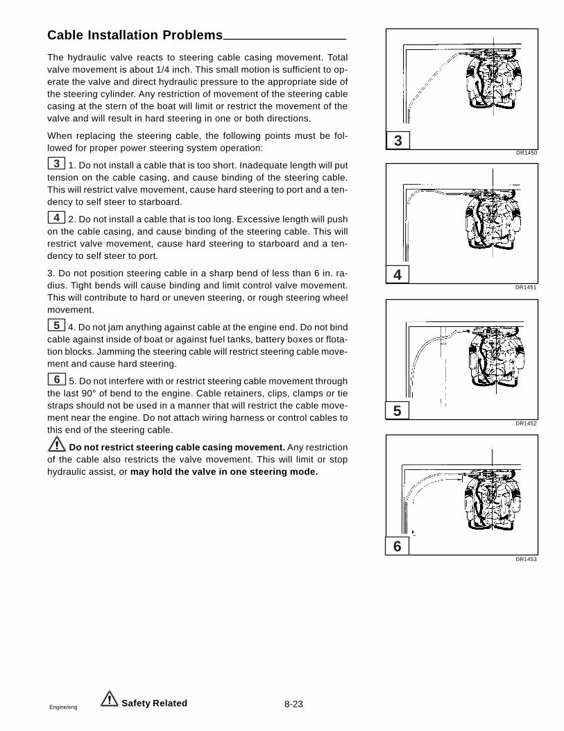
8-23Engine/eng
Cable Installation Problems
The hydraulic valve reacts to steering cable casing movement. Totalvalve movement is about 1/4 inch. This small motion is sufficient to op-erate the valve and direct hydraulic pressure to the appropriate side ofthe steering cylinder. Any restriction of movement of the steering cablecasing at the stern of the boat will limit or restrict the movement of thevalve and will result in hard steering in one or both directions.
When replacing the steering cable, the following points must be fol-lowed for proper power steering system operation:
3 1. Do not install a cable that is too short. Inadequate length will puttension on the cable casing, and cause binding of the steering cable.This will restrict valve movement, cause hard steering to port and a ten-dency to self steer to starboard.
4 2. Do not install a cable that is too long. Excessive length will pushon the cable casing, and cause binding of the steering cable. This willrestrict valve movement, cause hard steering to starboard and a ten-dency to self steer to port.
3. Do not position steering cable in a sharp bend of less than 6 in. ra-dius. Tight bends will cause binding and limit control valve movement.This will contribute to hard or uneven steering, or rough steering wheelmovement.
5 4. Do not jam anything against cable at the engine end. Do not bindcable against inside of boat or against fuel tanks, battery boxes or flota-tion blocks. Jamming the steering cable will restrict steering cable move-ment and cause hard steering.
6 5. Do not interfere with or restrict steering cable movement throughthe last 90° of bend to the engine. Cable retainers, clips, clamps or tiestraps should not be used in a manner that will restrict the cable move-ment near the engine. Do not attach wiring harness or control cables tothis end of the steering cable.
Do not restrict steering cable casing movement. Any restrictionof the cable also restricts the valve movement. This will limit or stophydraulic assist, or may hold the valve in one steering mode.
Safety Related
DR1450
DR1451
DR1452
DR1453
6
5
4
3
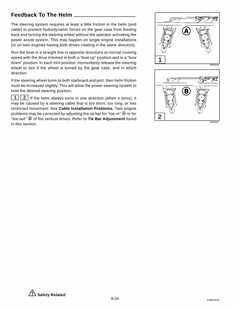
8-24 Engine/eng
Safety Related
Feedback To The Helm
The steering system requires at least a little friction in the helm (andcable) to prevent hydrodynamic forces on the gear case from feedingback and turning the steering wheel without the operator activating thepower assist system. This may happen on single engine installations(or on twin engines having both drives rotating in the same direction).
Run the boat in a straight line in opposite directions at normal cruisingspeed with the drive trimmed in both a “bow up” position and in a “bowdown” position. In each trim position, momentarily release the steeringwheel to see if the wheel is turned by the gear case, and in whichdirection.
If the steering wheel turns to both starboard and port, then helm frictionmust be increased slightly. This will allow the power steering system tohold the desired steering position.
1 2 If the helm always turns in one direction (when it turns), itmay be caused by a steering cable that is too short, too long, or hasrestricted movement. See Cable Installation Problems. Twin engineproblems may be corrected by adjusting the tie bar for “toe-in” A or for“toe-out” B of the vertical drives. Refer to Tie Bar Adjustment foundin this section.
DR5643
DR5644
1
2
8-25Engine/eng
Safety Related
Specification
Power Steering Pump Relief Valve Pressure ......................................................... 1000-1100 psi (6895-7584 kPa)
Torque Specifications
Component Torque
Anchor Screw - Cylinder assy. to Transom Plate 40-45 ft. lbs. (54-61 N•m)
Bolts - Power Steering Pump Mounting Bracket 25 ft. lbs. (34 N•m)
Bolts - Power Steering Pump Mounting 25 ft. lbs. (34 N•m)
Fitting - Power Steering Pump 37-75 ft. lbs. (50-102 N•m)
Fitting - Power Steering Pump Hose 15-26 ft. lbs. (20-35 N•m)
Fitting - Inlet Control Valve Hose 10-12 ft. lbs. (14-16 N•m)
Fitting - Outlet Control Valve Hose 15-17 ft. lbs. (20-23 N•m)
Hose Clamps - Oil Cooler and Power Steering Pump 12-17 in. lbs. (1,4-2,0 N•m)
Jam Nut - Anchor Block 35-40 ft. lbs. (47-54 N•m)
Locknut - Piston Rod To Clevis 23-28 ft. lbs. (31-38 N•m)
Nut - Steering Cable Anchor 120 in. lbs. (14 N•m)
Screw - Trim Tab 14-16 ft. lbs. (19-22 N•m)

8-26 Engine/eng
9-1Engine/eng
Section 9Throttle and Shift Control Systems
Table of Contents
9
Check Remote Control Shift Cable Stroke ....................................... 9-4Installation of SAE Cables to Engine/Drive ...................................... 9-5
Shift Cable to Vertical Drive ........................................................... 9-5Throttle Cable to Engine ................................................................. 9-6
Installation of Shift and Throttle Cables ........................................... 9-3Neutral Start Switch Tests ................................................................. 9-8Removal of SAE Cables From Engine/Drive .................................... 9-9
Shift Cable from Vertical Drive ....................................................... 9-9Throttle Cable from Engine ............................................................ 9-9
Sealants, Lubricants and Adhesives ................................................ 9-2
9-2 Engine/eng
Safety Warnings
Before working on any part of the steering system, read the Safetysection at the end of this manual.
Replace any locking type fastener (example: locknut or patchscrew) whose locking feature becomes weak. Definite resistanceto turning must be felt or locking fastener is not suitable for con-tinued use. Replace only with authorized replacement part orequivalent.
Sealants, Lubricants and Adhesives
Volvo Penta Grease
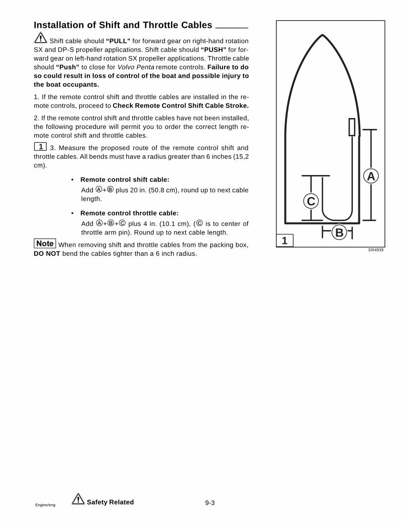
9-3Engine/eng Safety Related
Installation of Shift and Throttle Cables
Shift cable should “PULL” for forward gear on right-hand rotationSX and DP-S propeller applications. Shift cable should “PUSH” for for-ward gear on left-hand rotation SX propeller applications. Throttle cableshould “Push” to close for Volvo Penta remote controls. Failure to doso could result in loss of control of the boat and possible injury tothe boat occupants.
1. If the remote control shift and throttle cables are installed in the re-mote controls, proceed to Check Remote Control Shift Cable Stroke.
2. If the remote control shift and throttle cables have not been installed,the following procedure will permit you to order the correct length re-mote control shift and throttle cables.
1 3. Measure the proposed route of the remote control shift andthrottle cables. All bends must have a radius greater than 6 inches (15,2cm).
• Remote control shift cable:
Add A + B plus 20 in. (50.8 cm), round up to next cablelength.
• Remote control throttle cable:
Add A + B + C plus 4 in. (10.1 cm), ( C is to center ofthrottle arm pin). Round up to next cable length.
When removing shift and throttle cables from the packing box,DO NOT bend the cables tighter than a 6 inch radius.
DR4939
A
B
C
1
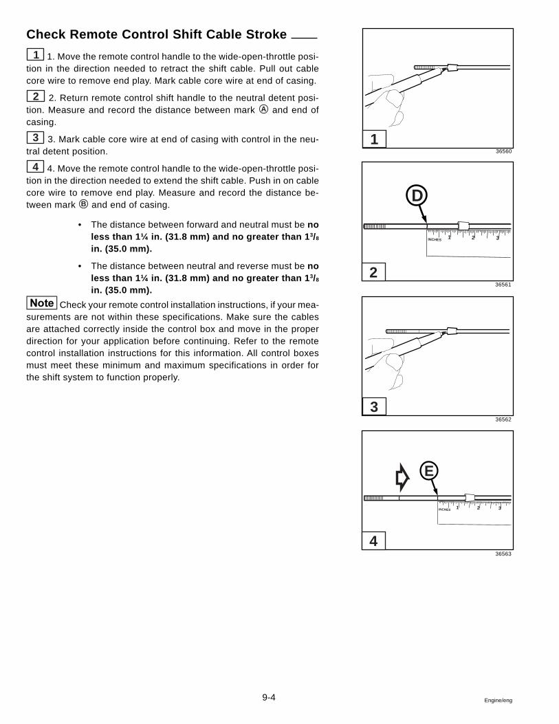
9-4 Engine/eng
Check Remote Control Shift Cable Stroke
1 1. Move the remote control handle to the wide-open-throttle posi-tion in the direction needed to retract the shift cable. Pull out cablecore wire to remove end play. Mark cable core wire at end of casing.
2 2. Return remote control shift handle to the neutral detent posi-tion. Measure and record the distance between mark A and end ofcasing.
3 3. Mark cable core wire at end of casing with control in the neu-tral detent position.
4 4. Move the remote control handle to the wide-open-throttle posi-tion in the direction needed to extend the shift cable. Push in on cablecore wire to remove end play. Measure and record the distance be-tween mark B and end of casing.
• The distance between forward and neutral must be noless than 1¼ in. (31.8 mm) and no greater than 1 3/8
in. (35.0 mm).
• The distance between neutral and reverse must be noless than 1¼ in. (31.8 mm) and no greater than 1 3/8
in. (35.0 mm).
Check your remote control installation instructions, if your mea-surements are not within these specifications. Make sure the cablesare attached correctly inside the control box and move in the properdirection for your application before continuing. Refer to the remotecontrol installation instructions for this information. All control boxesmust meet these minimum and maximum specifications in order forthe shift system to function properly.
36560
36561
36562
36563
INCHES 1 2 3
D
INCHES 1 2 3
E
1
2
3
4
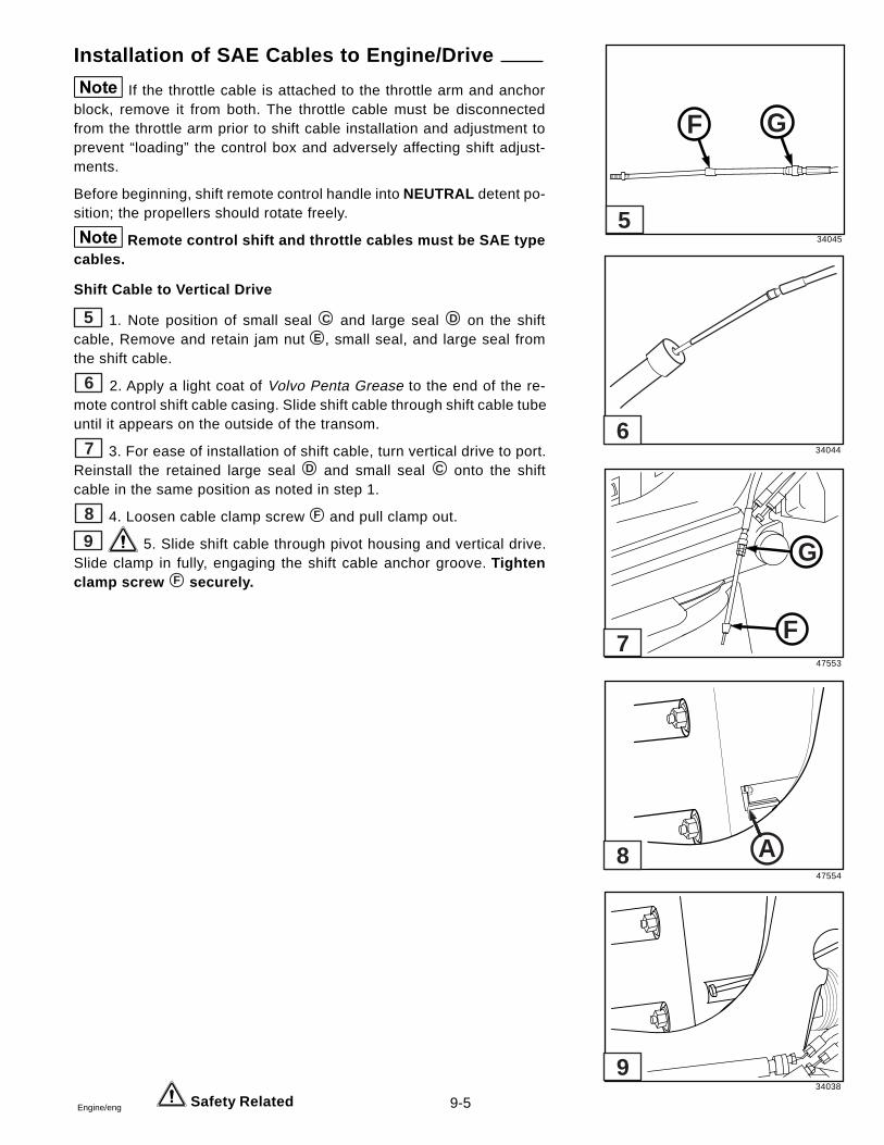
9-5Engine/eng Safety Related
Installation of SAE Cables to Engine/Drive
If the throttle cable is attached to the throttle arm and anchorblock, remove it from both. The throttle cable must be disconnectedfrom the throttle arm prior to shift cable installation and adjustment toprevent “loading” the control box and adversely affecting shift adjust-ments.
Before beginning, shift remote control handle into NEUTRAL detent po-sition; the propellers should rotate freely.
Remote control shift and throttle cables must be SAE typecables.
Shift Cable to Vertical Drive
5 1. Note position of small seal C and large seal D on the shiftcable, Remove and retain jam nut E , small seal, and large seal fromthe shift cable.
6 2. Apply a light coat of Volvo Penta Grease to the end of the re-mote control shift cable casing. Slide shift cable through shift cable tubeuntil it appears on the outside of the transom.
7 3. For ease of installation of shift cable, turn vertical drive to port.Reinstall the retained large seal D and small seal C onto the shiftcable in the same position as noted in step 1.
8 4. Loosen cable clamp screw F and pull clamp out.
9 5. Slide shift cable through pivot housing and vertical drive.Slide clamp in fully, engaging the shift cable anchor groove. Tightenclamp screw F securely.
34045
34044
47553
47554
34038
F G
F
G
A
5
6
7
8
9
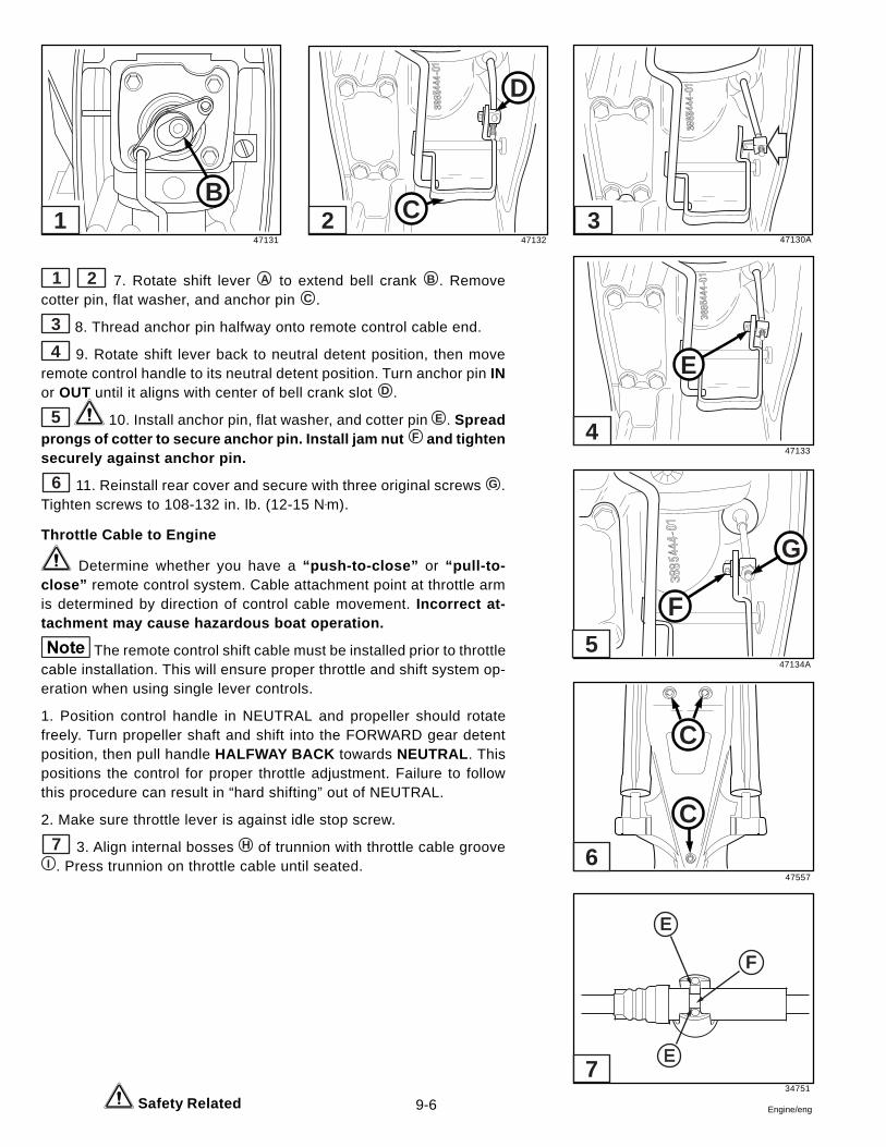
9-6 Engine/eng Safety Related
1 2 7. Rotate shift lever A to extend bell crank B . Removecotter pin, flat washer, and anchor pin C .
3 8. Thread anchor pin halfway onto remote control cable end.
4 9. Rotate shift lever back to neutral detent position, then moveremote control handle to its neutral detent position. Turn anchor pin INor OUT until it aligns with center of bell crank slot D .
5 10. Install anchor pin, flat washer, and cotter pin E . Spreadprongs of cotter to secure anchor pin. Install jam nut F and tightensecurely against anchor pin.
6 11. Reinstall rear cover and secure with three original screws G .Tighten screws to 108-132 in. lb. (12-15 N•m).
Throttle Cable to Engine
Determine whether you have a “push-to-close” or “pull-to-close” remote control system. Cable attachment point at throttle armis determined by direction of control cable movement. Incorrect at-tachment may cause hazardous boat operation.
The remote control shift cable must be installed prior to throttlecable installation. This will ensure proper throttle and shift system op-eration when using single lever controls.
1. Position control handle in NEUTRAL and propeller should rotatefreely. Turn propeller shaft and shift into the FORWARD gear detentposition, then pull handle HALFWAY BACK towards NEUTRAL . Thispositions the control for proper throttle adjustment. Failure to followthis procedure can result in “hard shifting” out of NEUTRAL.
2. Make sure throttle lever is against idle stop screw.
7 3. Align internal bosses H of trunnion with throttle cable grooveI . Press trunnion on throttle cable until seated.
47131 47132 47130A
47133
47134A
47557
34751
B
D
C
E
F
G
C
C
E
E
F
1 2 3
4
5
6
7
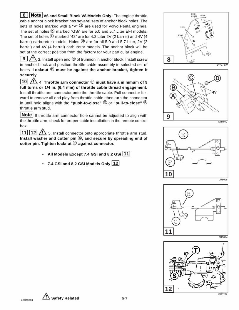
9-7Engine/eng
8 V6 and Small Block V8 Models Only: The engine throttlecable anchor block bracket has several sets of anchor block holes. Thesets of holes marked with a “V” J are used for Volvo Penta engines.The set of holes K marked “GSi” are for 5.0 and 5.7 Liter EFI models.The set of holes L marked “43” are for 4.3 Liter 2V (2 barrel) and 4V (4barrel) carburetor models. Holes M are for all 5.0 and 5.7 Liter, 2V (2barrel) and 4V (4 barrel) carburetor models. The anchor block will beset at the correct position from the factory for your particular engine.
9 3. Install open end N of trunnion in anchor block. Install screwin anchor block and position throttle cable assembly in selected set ofholes. Locknut O must be against the anchor bracket, tighten itsecurely.
10 4. Throttle arm connector P must have a minimum of 9full turns or 1/4 in. (6,4 mm) of throttle cable thread engagement.Install throttle arm connector onto the throttle cable. Pull connector for-ward to remove all end play from throttle cable, then turn the connectorin until hole aligns with the “push-to-close” Q or “pull-to-close” R
throttle arm stud.
If throttle arm connector hole cannot be adjusted to align withthe throttle arm, check for proper cable installation in the remote controlbox.
11 12 5. Install connector onto appropriate throttle arm stud.Install washer and cotter pin S , and secure by spreading end ofcotter pin. Tighten locknut T against connector.
• All Models Except 7.4 GSi and 8.2 GSi 11
• 7.4 GSi and 8.2 GSi Models Only 12
Safety Related
DRC7279
DR4977
DR5095
DR5094
DR5707
5.7GS
5.0GL
4.3GL4.3GS
5.0Gi5.7GSi
4V
DC
BA
E
F
H
G
8
9
10
11
12
9-8 Engine/eng
Neutral Start Switch Tests
Electrical
1. All switches must be in the “OFF” position, then discon-nect battery cables at the battery before servicing electrical sys-tems. Failure to do so could result in injury from:
• shorted battery positive (B+), causing a burn or anelectrical fire.
• contact with moving parts, if the engine is acciden-tally cranked or started.
2. Move the control handle to the NEUTRAL position. Disconnect theyellow/red lead from the key switch and the yellow/red lead from theinstrument wiring harness.
3. To test the continuity, calibrate an ohmmeter on high ohms scale.Connect the ohmmeter to the two leads. The meter should read zero(0).
4. Move the remote control handle to the FORWARD gear position.The meter should read infinity (¥). Move the remote control handle tothe REVERSE gear position. The meter should read infinity (¥).
5. If the meter does not show (¥), check the ohmmeter connectionsand test again. Replace the neutral start switch if the meter still fails toshow (¥) when the remote control handle is in the FORWARD andREVERSE gear position. Refer to the procedures in Disassembly ofRemote Control to replace the neutral safety switch.
Mechanical
1. With the boat in water and the remote control in NEUTRAL , turn theignition key to the start position. The engine should start.
2. Disengage the remote control handle and move it into the FOR-WARD warm-up position. The engine should start.
3. Disengage the remote control handle and move it into the REVERSEwarm-up position. Again the engine should start. Move the remote con-trol handle back into NEUTRAL .
4. Move the remote control handle to the FORWARD gear position.The engine should NOT start. Move the handle to the REVERSE gearposition. Again the engine should NOT start.
5. If the engine starts when the remote control handle is in either theFORWARD or REVERSE gear position, replace the neutral start switch.Refer to the procedures in Disassembly of Remote Control to re-place the neutral safety switch.
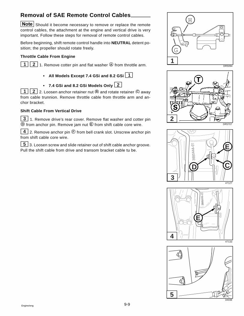
9-9Engine/eng
Removal of SAE Remote Control Cables
Should it become necessary to remove or replace the remotecontrol cables, the attachment at the engine and vertical drive is veryimportant. Follow these steps for removal of remote control cables.
Before beginning, shift remote control handle into NEUTRAL detent po-sition; the propeller should rotate freely.
Throttle Cable From Engine
1 2 1. Remove cotter pin and flat washer A from throttle arm.
• All Models Except 7.4 GSi and 8.2 GSi 1
• 7.4 GSi and 8.2 GSi Models Only 21 2 2. Loosen anchor retainer nut B and rotate retainer C away
from cable trunnion. Remove throttle cable from throttle arm and an-chor bracket.
Shift Cable From Vertical Drive
3 1. Remove drive’s rear cover. Remove flat washer and cotter pinD from anchor pin. Remove jam nut E from shift cable core wire.
4 2. Remove anchor pin F from bell crank slot. Unscrew anchor pinfrom shift cable core wire.
5 3. Loosen screw and slide retainer out of shift cable anchor groove.Pull the shift cable from drive and transom bracket cable tu be.
DR5094
DR5707
47127
47133
34038
H
G
D C
E
E
1
5
4
3
2

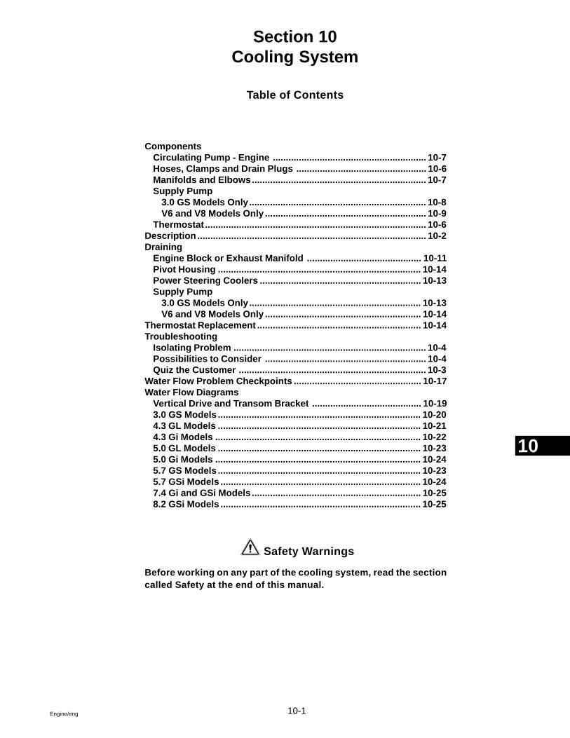
10-1Engine/eng
Section 10Cooling System
Table of Contents
ComponentsCirculating Pump - Engine ........................................................... 10-7Hoses, Clamps and Drain Plugs .................................................. 10-6Manifolds and Elbows................................................................... 10-7Supply Pump
3.0 GS Models Only.................................................................... 10-8V6 and V8 Models Only .............................................................. 10-9
Thermostat ..................................................................................... 10-6Description ........................................................................................ 10-2Draining
Engine Block or Exhaust Manifold ............................................ 10-11Pivot Housing .............................................................................. 10-14Power Steering Coolers .............................................................. 10-13Supply Pump
3.0 GS Models Only.................................................................. 10-13V6 and V8 Models Only ............................................................ 10-14
Thermostat Replacement ............................................................... 10-14Troubleshooting
Isolating Problem .......................................................................... 10-4Possibilities to Consider .............................................................. 10-4Quiz the Customer ........................................................................ 10-3
Water Flow Problem Checkpoints ................................................. 10-17Water Flow Diagrams
Vertical Drive and Transom Bracket .......................................... 10-193.0 GS Models .............................................................................. 10-204.3 GL Models .............................................................................. 10-214.3 Gi Models ............................................................................... 10-225.0 GL Models .............................................................................. 10-235.0 Gi Models ............................................................................... 10-245.7 GS Models .............................................................................. 10-235.7 GSi Models ............................................................................. 10-247.4 Gi and GSi Models ................................................................. 10-258.2 GSi Models ............................................................................. 10-25
Safety Warnings
Before working on any part of the cooling system, read the sectioncalled Safety at the end of this manual.
10
10-2 Engine/eng
Description
1 Water is supplied to the engine by means of an impeller type pump(supply pump). The water supply pump is mounted on the engine. Wa-ter supplied to the engine is circulated in the engine by means of acentrifugal type pump (circulating pump).
All models use a crankshaft mounted pump. During low speed opera-tion the impeller functions as a positive displacement pump. At higherspeeds it functions as a combination centrifugal and positive displace-ment pump.
The shape of the housing and/or liner cause an eccentric action of theimpeller blades during engine operation. During periods of high speedoperation, the resistance of the water on its way through the pump issufficient to prevent the ends of the impeller blades from making con-tact and following the inside perimeter of the pump housing. The bladesmerely flex in toward the center of the impeller to perform as a combi-nation centrifugal and positive displacement pump.
2 3 The circulating pump is mounted on the front of the cylinderblock. It has a pulley bolted to the pump shaft hub at its forward end.This in turn is driven by means of a belt from the crankshaft pulley. Thepump shaft and bearing assembly is pressed in the water pump hous-ing. The bearing is permanently lubricated during manufacture andsealed to prevent loss of lubricant and entry of dirt. The pump is sealedagainst coolant leakage by a non-adjustable seal assembly pressedinto the pump cover.
Cooling water for the engine is picked up at the water intakes on bothsides of the lower gearcase. Water is pulled upward thru the lowergearcase until it enters a water tube that transfers it to the upper gearhousing.
Water is pulled through the upper gear housing water passage where itmeets a nipple and hose attached to the pivot housing. Water is routedthrough the transom mount assembly to a tube that’s mounted on theinside of the gimbal housing. From this tube the water is drawn througha supply hose that’s connected to the inside nipple of the supply pump.Water exits the outside nipple of the supply pump under pressure andcarried through a hose to the inlet nipple of the thermostat housing.
DRC7621
DRC6871
DRC6872
3
2
1
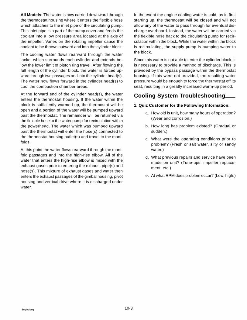
10-3Engine/eng
All Models: The water is now carried downward throughthe thermostat housing where it enters the flexible hosewhich attaches to the inlet pipe of the circulating pump.This inlet pipe is a part of the pump cover and feeds thecoolant into a low pressure area located at the axis ofthe impeller. Vanes on the rotating impeller cause thecoolant to be thrown outward and into the cylinder block.
The cooling water flows rearward through the waterjacket which surrounds each cylinder and extends be-low the lower limit of piston ring travel. After flowing thefull length of the cylinder block, the water is forced up-ward through two passages and into the cylinder head(s).The water now flows forward in the cylinder head(s) tocool the combustion chamber areas.
At the forward end of the cylinder head(s), the waterenters the thermostat housing. If the water within theblock is sufficiently warmed up, the thermostat will beopen and a portion of the water will be pumped upwardpast the thermostat. The remainder will be returned viathe flexible hose to the water pump for recirculation withinthe powerhead. The water which was pumped upwardpast the thermostat will enter the hose(s) connected tothe thermostat housing outlet(s) and travel to the mani-folds.
At this point the water flows rearward through the mani-fold passages and into the high-rise elbow. All of thewater that enters the high-rise elbow is mixed with theexhaust gases prior to entering the exhaust pipe(s) andhose(s). This mixture of exhaust gases and water thenenters the exhaust passages of the gimbal housing, pivothousing and vertical drive where it is discharged underwater.
In the event the engine cooling water is cold, as in firststarting up, the thermostat will be closed and will notallow any of the water to pass through for eventual dis-charge overboard. Instead, the water will be carried viathe flexible hose back to the circulating pump for recir-culation within the block. While the water within the blockis recirculating, the supply pump is pumping water tothe block.
Since this water is not able to enter the cylinder block, itis necessary to provide a method of discharge. This isprovided by the bypass passage within the thermostathousing. If this were not provided, the resulting waterpressure would be enough to force the thermostat off itsseat, resulting in a greatly increased warm-up period.
Cooling System Troubleshooting
1. Quiz Customer for the Following Information:
a. How old is unit, how many hours of operation?(Wear and corrosion.)
b. How long has problem existed? (Gradual orsudden.)
c. What were the operating conditions prior toproblem? (Fresh or salt water, silty or sandywater.)
d. What previous repairs and service have beenmade on unit? (Tune-ups, impeller replace-ment, etc.)
e. At what RPM does problem occur? (Low, high.)
10-4 Engine/eng
2. Possibilities To Consider:
a. Temperature Gauge Malfunction.
• Improper or defective sender unit
• Malfunctioning gauge - Check ground wire - substitutegood gauge.
b. Engine Water Circulation Pump Malfunction.
• Loose alternator belt
• Impeller vanes worn - replace pump.
• Impeller shaft seal failure - replace pump.
c. Water Intake Screens Blocked.
d. Ventilation - Marine growth on keel, hull deformities, etc.
e. Ignition Timing
• Running with retarded timing - Check timing.
3. Isolating Cooling Problem:
Air or exhaust gas entering cooling water:
a. Procedure - Replace water hose between thermostat hous-ing and the supply pump with clear plastic hose. Operate unitin test tank or boat in water at RPM at which overheat occurs.
If operating unit in test tank, run motor in neutral. Some testtanks may not have sufficient water volume to allow running engine ingear without creating turbulence. This can be picked up by the waterintake and misconstrued as evidence of a cooling problem.
b. Results and Conclusions - No bubbles in hose, air/ exhaustis not entering cooling water. Bubbles in hose, air/exhaust isentering cooling water.
c. Check for - Defective lower gearcase water tube guide andseals; damaged water tube grommet; leaking water passagecover gasket or adaptor-to-gear housing gasket.
10-5Engine/eng
Insufficient water supply:
a. Procedure - Disconnect water supply hose from transombracket at thermostat housing. Operate engine at specified idleRPM. Hold end of hose level with the top of the flame arrestor.
b. Results and Conclusions - A 1 inch (2,5 cm) head of waterdischarge, water supply is good. If less than 1/2 inch (1.2 cm),look for source of water loss.
c. Check for - Blocked intake screens; damaged impeller hous-ing O-ring or impeller plate gasket; broken or worn impeller;defective pivot housing water passage O-ring or water drainscrew seal; loose pivot housing-to-gimbal housing water hoseclamps.
Thermostat malfunction
a. Procedure - Operate engine until indicated temperature ex-ceeds 160°F (71° C). Touch hoses between thermostat andexhaust manifolds.
b. Results and Conclusions - Hoses cold, thermostat is stuckclosed. Hoses warm or hot, thermostat is good.
c. Check for - Thermostat stuck open or closed, defective ther-mostat O-ring, correct thermostat style for engine type, clearthermostat housing bypass passage.
Engine head gasket leakage
a. Procedure - Allow engine to cool. Replace water hose(s) be-tween thermostat housing and exhaust manifolds) with clearplastic hose. Operate unit at RPM at which overheat occurs.
b. Results and Conclusions - No bubbles evident, head gas-kets not leaking. Bubbles evident, head gaskets leaking.
c. Check for - Cylinder compression using appropriate tester, wa-ter in engine oil, water in cylinders, spark plugs wet with water.
- overheating or slow warm-up:
- overheating or hard starting (water incylinders):
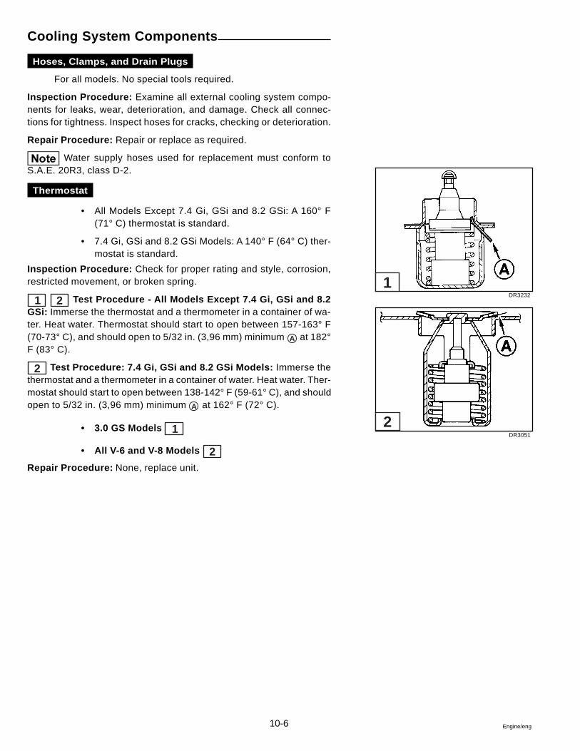
10-6 Engine/eng
Cooling System Components
Hoses, Clamps, and Drain Plugs
For all models. No special tools required.
Inspection Procedure: Examine all external cooling system compo-nents for leaks, wear, deterioration, and damage. Check all connec-tions for tightness. Inspect hoses for cracks, checking or deterioration.
Repair Procedure: Repair or replace as required.
Water supply hoses used for replacement must conform toS.A.E. 20R3, class D-2.
Thermostat
• All Models Except 7.4 Gi, GSi and 8.2 GSi: A 160° F(71° C) thermostat is standard.
• 7.4 Gi, GSi and 8.2 GSi Models: A 140° F (64° C) ther-mostat is standard.
Inspection Procedure: Check for proper rating and style, corrosion,restricted movement, or broken spring.
1 2 Test Procedure - All Models Except 7.4 Gi, GSi and 8.2GSi: Immerse the thermostat and a thermometer in a container of wa-ter. Heat water. Thermostat should start to open between 157-163° F(70-73° C), and should open to 5/32 in. (3,96 mm) minimum A at 182°F (83° C).
2 Test Procedure: 7.4 Gi, GSi and 8.2 GSi Models: Immerse thethermostat and a thermometer in a container of water. Heat water. Ther-mostat should start to open between 138-142° F (59-61° C), and shouldopen to 5/32 in. (3,96 mm) minimum A at 162° F (72° C).
• 3.0 GS Models 1
• All V-6 and V-8 Models 2Repair Procedure: None, replace unit.
DR3232
DR3051
1
2
10-7Engine/eng
Manifolds and Elbows
For all models. No special tools required.
Inspection Procedure: Pressure check components for leaks. Disas-semble and inspect for corrosion or accumulation of foreign material.
Repair Procedure: Rod out any accumulation of foreign matter built upin water passages. If evidence of porosity between water passages andexhaust chambers or exterior is found, replace component. Install newgaskets on reassembly.
Circulating Pump - Engine
For all models. No special tools required.
Inspection Procedure: Make sure belt tension is correct. With the en-gine running, observe the rotation of the circulating pump pulley. If thepulley does not run true it can cause excessive drive belt wear and dam-age to the circulating pump itself.
If the leakage of water occurs at the circulating pump while the engine isin operation, the pump may be loosely mounted to the engine, the shaftseal in front of the pump may be bad, the backing plate gasket may bedefective, or the circulating pump mounting gaskets are leaking.
If the above inspections do not detect any defect, the pump must beremoved and inspected for internal corrosion, blockage, or damage. In-spect impeller for erosion.
Repair Procedure: None, replace the pump.
Volvo Penta marine engines have a special circulating waterpump with stainless steel components and a special marine shaft sealassembly. Do not replace with an automotive water pump.
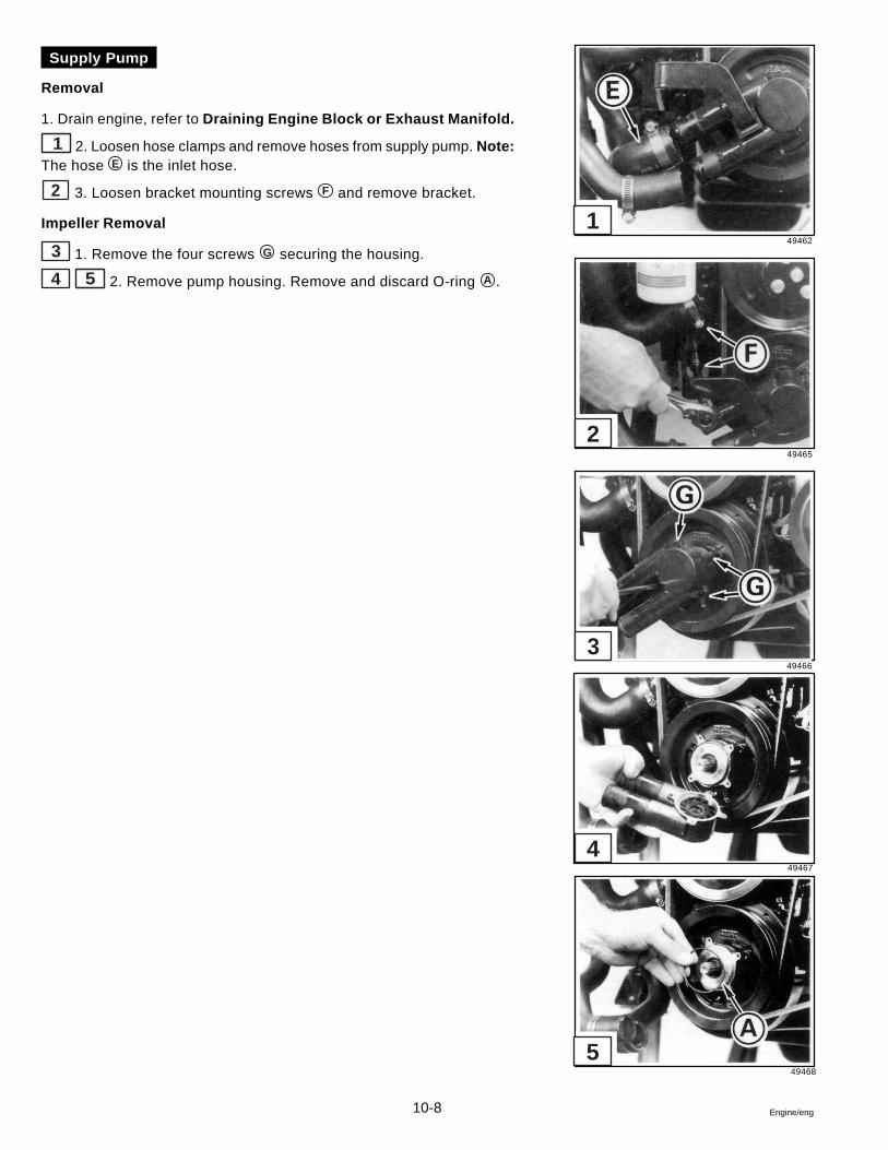
10-8 Engine/eng
49467
49468
5
4
Supply Pump
Removal
1. Drain engine, refer to Draining Engine Block or Exhaust Manifold.
1 2. Loosen hose clamps and remove hoses from supply pump. Note:The hose E is the inlet hose.
2 3. Loosen bracket mounting screws F and remove bracket.
Impeller Removal
3 1. Remove the four screws G securing the housing.
4 5 2. Remove pump housing. Remove and discard O-ring A .
49462
49465
49466
3
2
1
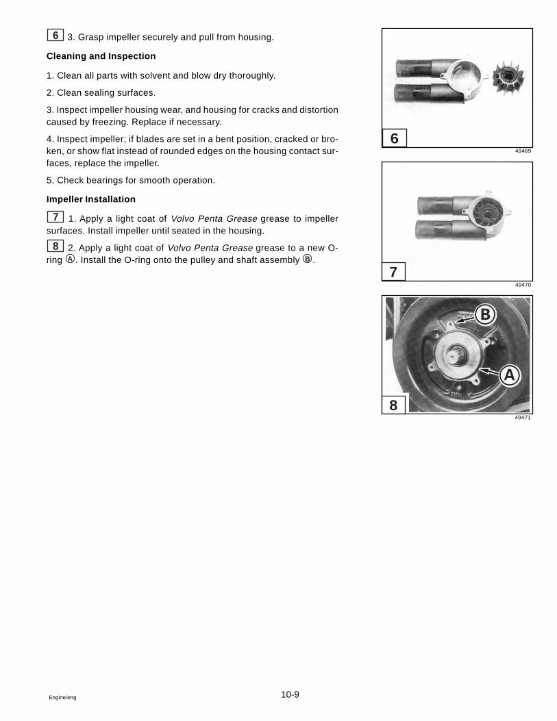
10-9Engine/eng
6 3. Grasp impeller securely and pull from housing.
Cleaning and Inspection
1. Clean all parts with solvent and blow dry thoroughly.
2. Clean sealing surfaces.
3. Inspect impeller housing wear, and housing for cracks and distortioncaused by freezing. Replace if necessary.
4. Inspect impeller; if blades are set in a bent position, cracked or bro-ken, or show flat instead of rounded edges on the housing contact sur-faces, replace the impeller.
5. Check bearings for smooth operation.
Impeller Installation
7 1. Apply a light coat of Volvo Penta Grease grease to impellersurfaces. Install impeller until seated in the housing.
8 2. Apply a light coat of Volvo Penta Grease grease to a new O-ring A . Install the O-ring onto the pulley and shaft assembly B .
49469
49470
49471
8
7
6
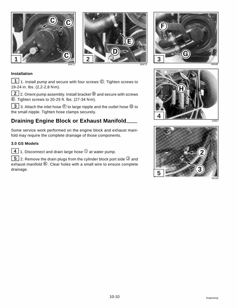
10-10 Engine/eng
Installation
1 1. Install pump and secure with four screws C . Tighten screws to19-24 in. lbs. (2,2-2,8 N•m).
2 2. Orient pump assembly. Install bracket D and secure with screwsE . Tighten screws to 20-25 ft. lbs. (27-34 N•m).
3 3. Attach the inlet hose F to large nipple and the outlet hose G tothe small nipple. Tighten hose clamps securely.
Draining Engine Block or Exhaust Manifold
Some service work performed on the engine block and exhaust mani-fold may require the complete drainage of those components.
3.0 GS Models
4 1. Disconnect and drain large hose I at water pump.
5 2. Remove the drain plugs from the cylinder block port side J andexhaust manifold K . Clear holes with a small wire to ensure completedrainage.
49472 49473 49448
23907
46195
5
4
321
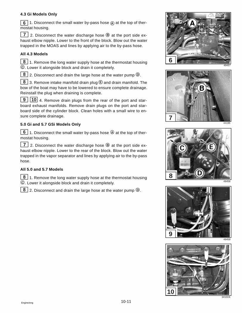
10-11Engine/eng
4.3 Gi Models Only
6 1. Disconnect the small water by-pass hose A at the top of ther-mostat housing.
7 2. Disconnect the water discharge hose B at the port side ex-haust elbow nipple. Lower to the front of the block. Blow out the watertrapped in the MOAS and lines by applying air to the by-pass hose.
All 4.3 Models
8 1. Remove the long water supply hose at the thermostat housingC . Lower it alongside block and drain it completely.
8 2. Disconnect and drain the large hose at the water pump D .
8 3. Remove intake manifold drain plug E and drain manifold. Thebow of the boat may have to be lowered to ensure complete drainage.Reinstall the plug when draining is complete.
9 10 4. Remove drain plugs from the rear of the port and star-board exhaust manifolds. Remove drain plugs on the port and star-board side of the cylinder block. Clean holes with a small wire to en-sure complete drainage.
5.0 Gi and 5.7 GSi Models Only
6 1. Disconnect the small water by-pass hose A at the top of ther-mostat housing.
7 2. Disconnect the water discharge hose B at the port side ex-haust elbow nipple. Lower to the rear of the block. Blow out the watertrapped in the vapor separator and lines by applying air to the by-passhose.
All 5.0 and 5.7 Models
8 1. Remove the long water supply hose at the thermostat housingC . Lower it alongside block and drain it completely.
8 2. Disconnect and drain the large hose at the water pump D .
49457
44195
49458
49459
34102A
10
9
8
7
6
10-12 Engine/eng
49462
All 5.0 and 5.7 Models (continued)
1 2 3. Remove drain plugs F at the rear of each port and star-board exhaust manifold, and remove drain plugs G on both sides of thecylinder block. Clear holes with a small wire to ensure complete drain-age.
All 7.4 and 8.2 Models
3 1. Remove the long water supply hose at the thermostat housing
C . Lower it alongside the engine and drain it completely.
3 2. Disconnect and drain the large hose at the water pump D .
3 3. Drain the small water by-pass hose H between MOAS the top ofthermostat housing. Disconnect the hose at the thermostat housing andlower it alongside the engine and drain it completely.
4 5 4. Remove the rubber cap at the rear of each port and star-board exhaust manifold. On 7.4Gi, remove drain plug on starboard sideand remove knock sensor on port side. On 7.4 and 8.2GSi Models re-move drain plugs on both sides of the cylinder block. Clear holes with asmall wire to ensure complete drainage.
Draining Supply Pump
6 1. Loosen and slide hose clamps back. Remove hoses A from thepump and drain.
2. Crank the engine no more than 2 seconds (DO NOT START) to expelany water trapped in water pump. Reattach hoses.
49461 49460 42863
28283
28284
1 2 3
4
5
6
10-13Engine/eng
Thermostat Replacement
3.0 GS Models
7 1. Remove all hoses B from the thermostat housing.
8 2. Remove the engine coolant temperature sender nut, lead andwashers C from the sender.
9 3. Remove two screws E securing thermostat housing to the cyl-inder head. Remove the housing from the head. Clean all gasket sur-faces.
10 4. Remove thermostat O-ring F and thermostat G from the hous-ing.
10 11 5. Install thermostat G into the thermostat housing with thepointed end H facing into the housing. Place the O-ring F into posi-tion in the O-ring groove to retain the thermostat.
45332
45333
45335
45354
10
9
8
7
45355
11
10-14 Engine/eng
1 6. Place a new gasket I into position at the front of the head.
No sealer is required with this gasket.
2 7. Install the thermostat housing into position and secure with twoscrews E . Tighten the screws to 12-16 ft. lbs. (16-22 N•m).
3 8. Attach the engine coolant temperature sender washers, leadand nut C to the sender. Tighten the nut securely. Install Temperature
switch lead onto switch terminal D .
4 9. Install all hoses B and secure with clamps. Tighten the clampssecurely.
45356
45357
45345
45344
4
3
2
1
10-15Engine/eng
All V-6 and V-8 Models
5 6 1. Remove all water hoses from the thermostat housing.
• Carburetor Models: four hoses A 5
• EFI Models: five hoses B 67 2. Note position of lifting eye C . Remove two screws D then
remove lifting eye and thermostat housing.
8 3. The thermostat E is held in place by an O-ring. Pry the O-ringout of its groove, then lift the thermostat out of the housing.
4. Discard the housing gasket and O-ring. Thoroughly clean the hous-ing and manifold gasket surfaces.
8 5. Place the thermostat in the housing. The temperature sensingelement E must face you when installed. Install a new O-ring to sealthermostat in housing. Make sure O-ring is completely seated in itsgroove.
7 6. Coat both sides of a new gasket with Volvo Penta Gasket Seal-ing Compound and place it on the manifold. Position thermostat hous-ing and lifting eye on engine adapter as noted in Step 2. Install two lockwashers and screws D . Tighten the screws to 20-25 ft. lbs. (27-34N•m).
9 7. Connect the water supply hose to nipple F and tighten hoseclamp securely. Connect the three remaining water hoses and tightenhose clamps securely. Make sure lifting eye C is positioned as shown.
If the water supply hose is attached to the wrong nipple, theengine will overheat.
28546
38259
28548
14649
28547
9
8
7
6
5
10-16 Engine/eng
Numbers refer to Cooling System Flow Diagrams.
1 Intake Screen - Blocked with debris.
2 Water Tube Guide and Seal - Improperly sealed.
3 Water Tube - Plugged with debris.
4 Grommet - Deteriorated, improperly seated.
5 Upper Gear Housing - Debris blocking passage,freeze damaged.
6 Pivot Housing Seal - Damaged, out of position,improperly sealed.
7 Nipple O-ring - Out of position, improperly sealed,damaged.
8 Nipple - Blocked by debris, freeze cracked.
9 Water Hose and Clamps - Clamps loose, hosecollapsed or leaking.
10 Transom Mount Water Tube - Blocked by debris.
11 Supply Pump (Engine Mounted) - Failed seal,corroded or bad bear ings, eroded impeller, leak-ing mounting gaskets or backing plate.
12 Thermostat Housing - Corroded, restricted, orleaking gasket.
13 Thermostat - Defective thermostat, or wrong typefor en- gine; improperly seated or damaged O-ring.
14 Belts - Loose, or worn and slipping.
15 Circulating Pump (Engine) - Failed seal, corrodedor bad bearings, eroded impeller, leaking mount-ing gaskets or backing plate.
16 Cylinder Block Water Passages - Corrosion, slag,blocked passages, or leaking core plugs.
17 Cylinder Head - Corrosion, slag, blocked passagesor leaking gaskets.
18 Exhaust Manifold, Elbows, Gaskets, and Hoses- Gaskets improperly installed; corrosion, sand, orslag in manifold and elbows; hoses collapsed,burned through, or leaking.
19 Exhaust Pipe and Seal - Improperly sealed or in-stalled, leaking.
20 Bellows, Clamp, and Retainer - Loose clamp,detached or torn bellows.
21 Power Steering Cooler - Restricted, or crackedand leaking.
22 Intake Manifold - Cracked casting, or leakinggasket(s).
23 Engine Oil Cooler - Restricted, or cracked andleaking.
24 7.4 and 8.2 Models: Check Valve - Water By-passHose - Plugged with debris.
In addition, check:
• Ignition Timing
• Boat Hull - Condition of hull, marinegrowth, or under- hull equipment.
Fittings protruding through hull may cause airbubble streams which can be picked up by the lowergearcase and mixed with incoming cooling water to causean overheat condition.
Water Flow Problem Checkpoints:
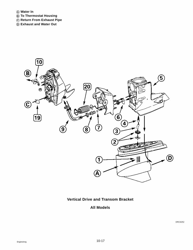
10-17Engine/eng
Vertical Drive and Transom Bracket
All Models
DRC6252
A Water InB To Thermostat HousingC Return From Exhaust PipeD Exhaust and Water Out
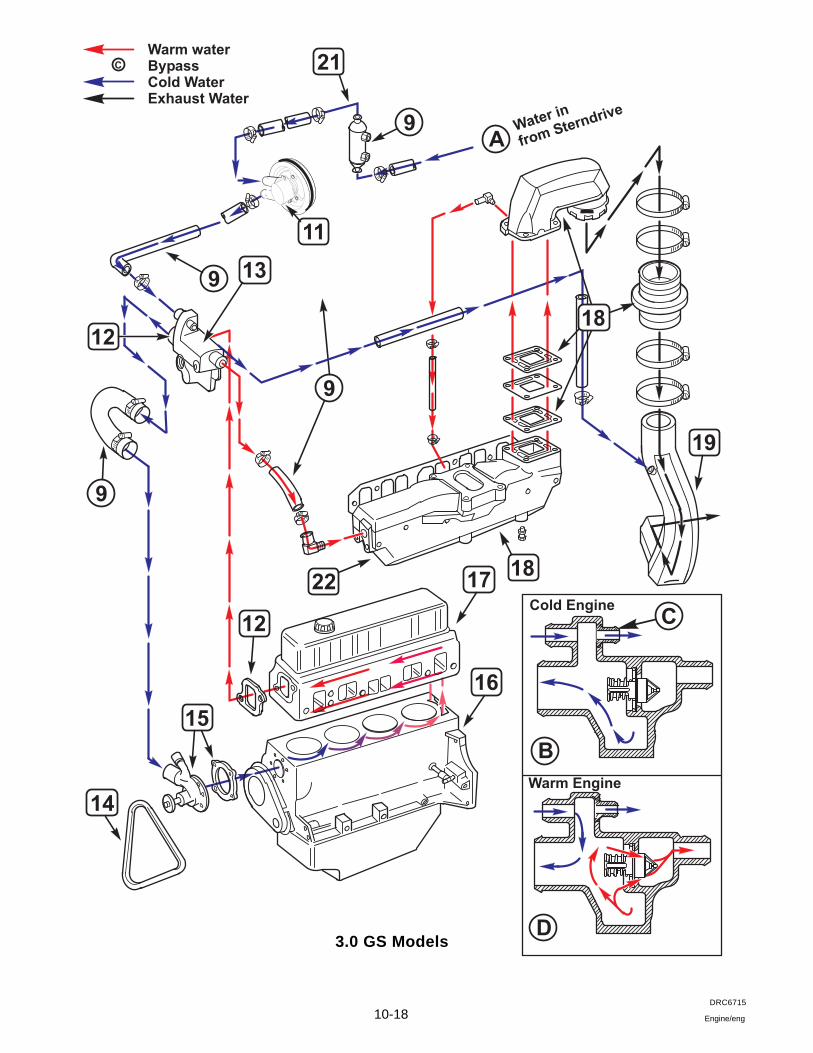
10-18 Engine/eng
3.0 GS Models
DRC6715
B
D
12
12
22
14
17
16
9
9A
21
9
9
18
19
15
13
Warm waterBypassCold WaterExhaust Water
Cold Engine
Warm Engine
C
Water in
from Sterndrive
C
11
18
10-19Engine/eng
4.3 GL Models
DRC7625
10-20 Engine/eng
4.3 Gi Models
DRC7626
10-21Engine/eng
5.0 GL and 5.7 GS Models
DRC7627
10-22 Engine/eng
5.0 Gi and 5.7 GSi Models
DRC7628
10-23Engine/eng
7.4 Gi, GSi and 8.2 GSi Models
DRC7629

10-24 Engine/eng
11-1Engine/eng
Section 11Engine Removal and Installation
Table of Contents
EngineAlignment ...................................................................................... 11-7Installation ..................................................................................... 11-6Removal ......................................................................................... 11-2
Determining Minimum Engine Height ........................................... 11-12Engine Mounts, Rear ...................................................................... 11-11Exhaust Pipe Replacement ............................................................. 11-6
Safety Warnings
Before working on any part of the engine, read the Safety sectionat end of this manual.
Proper installation is important for the safe, reliable operation ofall mechanical products. The procedures we recommend and de-scribe in these instructions are effective methods to be followedwhen removing or installing the engine. Some of these methodsrequire the use of tools specially designed for the purpose. Thespecial tools should be used when and as recommended.
Special Tools
Alignment Tool 3851083-0Universal Handle 3850609-3
Sealants, Lubricants and Adhesives
Volvo Penta Gasket Sealing CompoundVolvo Penta Grease3M Adhesive
11
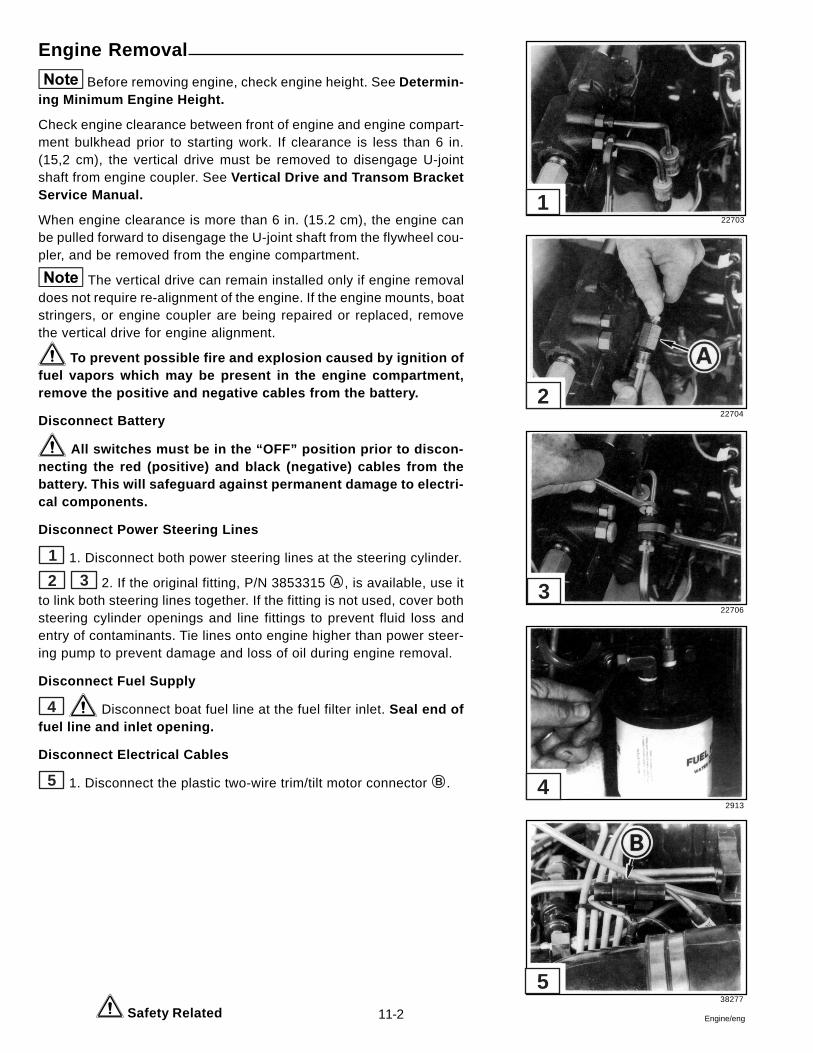
11-2 Engine/eng
Engine Removal
Before removing engine, check engine height. See Determin-ing Minimum Engine Height.
Check engine clearance between front of engine and engine compart-ment bulkhead prior to starting work. If clearance is less than 6 in.(15,2 cm), the vertical drive must be removed to disengage U-jointshaft from engine coupler. See Vertical Drive and Transom BracketService Manual.
When engine clearance is more than 6 in. (15.2 cm), the engine canbe pulled forward to disengage the U-joint shaft from the flywheel cou-pler, and be removed from the engine compartment.
The vertical drive can remain installed only if engine removaldoes not require re-alignment of the engine. If the engine mounts, boatstringers, or engine coupler are being repaired or replaced, removethe vertical drive for engine alignment.
To prevent possible fire and explosion caused by ignition offuel vapors which may be present in the engine compartment,remove the positive and negative cables from the battery.
Disconnect Battery
All switches must be in the “OFF” position prior to discon-necting the red (positive) and black (negative) cables from thebattery. This will safeguard against permanent damage to electri-cal components.
Disconnect Power Steering Lines
1 1. Disconnect both power steering lines at the steering cylinder.
2 3 2. If the original fitting, P/N 3853315 A , is available, use itto link both steering lines together. If the fitting is not used, cover bothsteering cylinder openings and line fittings to prevent fluid loss andentry of contaminants. Tie lines onto engine higher than power steer-ing pump to prevent damage and loss of oil during engine removal.
Disconnect Fuel Supply
4 Disconnect boat fuel line at the fuel filter inlet. Seal end offuel line and inlet opening.
Disconnect Electrical Cables
5 1. Disconnect the plastic two-wire trim/tilt motor connector B .
Safety Related
22703
22704
22706
2913
38277
5
4
3
2
1
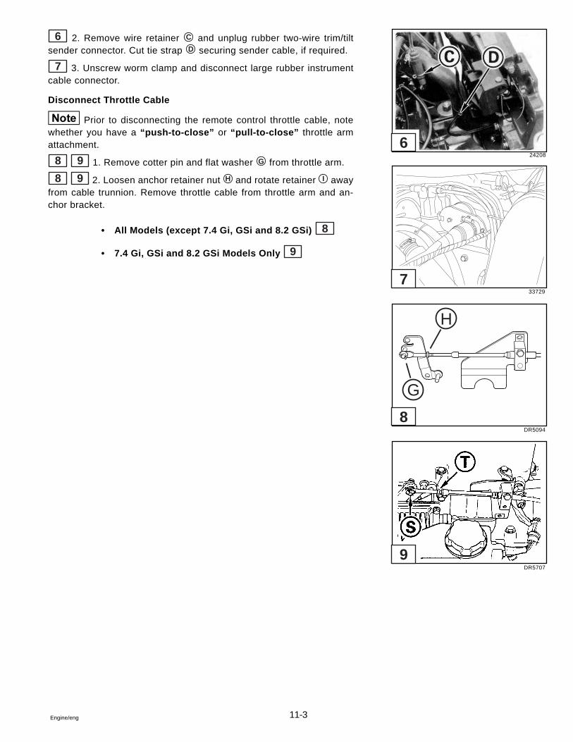
11-3Engine/eng
6 2. Remove wire retainer C and unplug rubber two-wire trim/tiltsender connector. Cut tie strap D securing sender cable, if required.
7 3. Unscrew worm clamp and disconnect large rubber instrumentcable connector.
Disconnect Throttle Cable
Prior to disconnecting the remote control throttle cable, notewhether you have a “push-to-close” or “pull-to-close” throttle armattachment.
8 9 1. Remove cotter pin and flat washer G from throttle arm.
8 9 2. Loosen anchor retainer nut H and rotate retainer I awayfrom cable trunnion. Remove throttle cable from throttle arm and an-chor bracket.
• All Models (except 7.4 Gi, GSi and 8.2 GSi) 8
• 7.4 Gi, GSi and 8.2 GSi Models Only 9
24208
33729
DR5094
DR5707
H
G
9
8
7
6
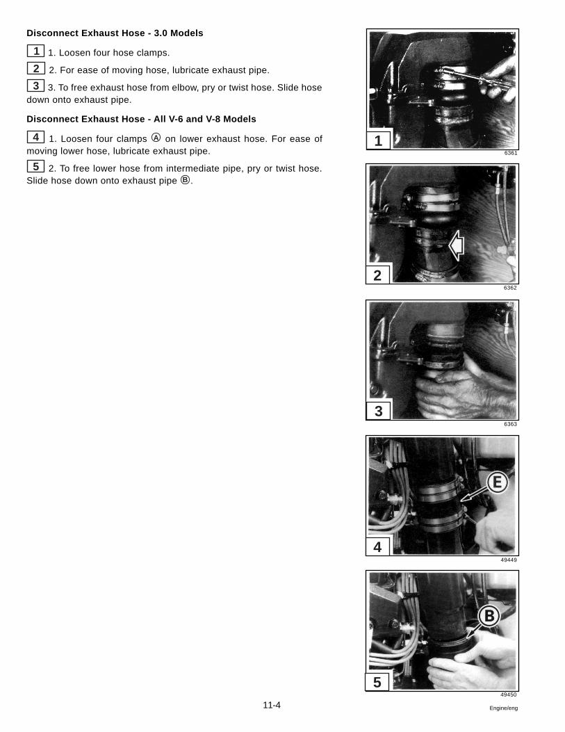
11-4 Engine/eng
Disconnect Exhaust Hose - 3.0 Models
1 1. Loosen four hose clamps.
2 2. For ease of moving hose, lubricate exhaust pipe.
3 3. To free exhaust hose from elbow, pry or twist hose. Slide hosedown onto exhaust pipe.
Disconnect Exhaust Hose - All V-6 and V-8 Models
4 1. Loosen four clamps A on lower exhaust hose. For ease ofmoving lower hose, lubricate exhaust pipe.
5 2. To free lower hose from intermediate pipe, pry or twist hose.Slide hose down onto exhaust pipe B .
6361
6362
6363
49449
49450
5
4
3
2
1
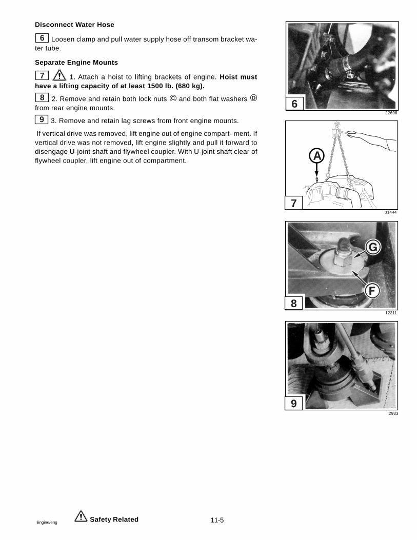
11-5Engine/eng
Disconnect Water Hose
6 Loosen clamp and pull water supply hose off transom bracket wa-ter tube.
Separate Engine Mounts
7 1. Attach a hoist to lifting brackets of engine. Hoist musthave a lifting capacity of at least 1500 lb. (680 kg).
8 2. Remove and retain both lock nuts C and both flat washers D
from rear engine mounts.
9 3. Remove and retain lag screws from front engine mounts.
If vertical drive was removed, lift engine out of engine compart- ment. Ifvertical drive was not removed, lift engine slightly and pull it forward todisengage U-joint shaft and flywheel coupler. With U-joint shaft clear offlywheel coupler, lift engine out of compartment.
Safety Related
22698
31444
12211
2933
A
9
8
7
6
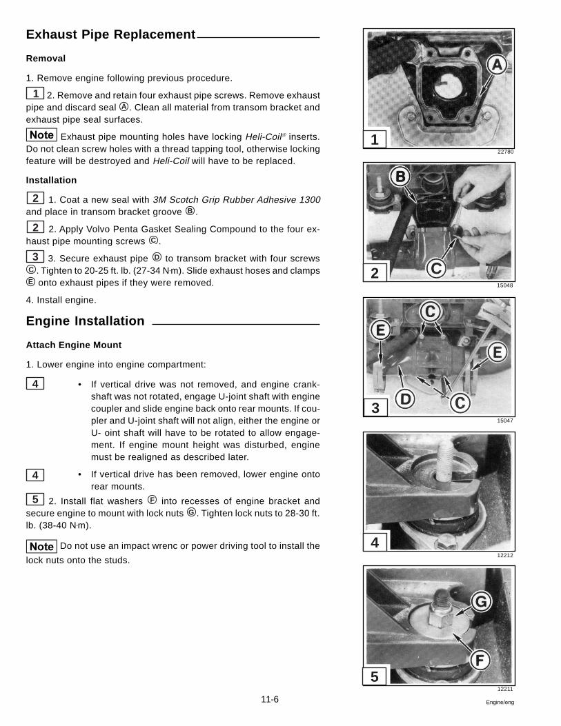
11-6 Engine/eng
Exhaust Pipe Replacement
Removal
1. Remove engine following previous procedure.
1 2. Remove and retain four exhaust pipe screws. Remove exhaustpipe and discard seal A . Clean all material from transom bracket andexhaust pipe seal surfaces.
Exhaust pipe mounting holes have locking Heli-Coilâ inserts.Do not clean screw holes with a thread tapping tool, otherwise lockingfeature will be destroyed and Heli-Coil will have to be replaced.
Installation
2 1. Coat a new seal with 3M Scotch Grip Rubber Adhesive 1300and place in transom bracket groove B .
2 2. Apply Volvo Penta Gasket Sealing Compound to the four ex-haust pipe mounting screws C .
3 3. Secure exhaust pipe D to transom bracket with four screwsC . Tighten to 20-25 ft. lb. (27-34 N•m). Slide exhaust hoses and clampsE onto exhaust pipes if they were removed.
4. Install engine.
Engine Installation
Attach Engine Mount
1. Lower engine into engine compartment:
• If vertical drive was not removed, and engine crank-shaft was not rotated, engage U-joint shaft with enginecoupler and slide engine back onto rear mounts. If cou-pler and U-joint shaft will not align, either the engine orU- oint shaft will have to be rotated to allow engage-ment. If engine mount height was disturbed, enginemust be realigned as described later.
• If vertical drive has been removed, lower engine ontorear mounts.
5 2. Install flat washers F into recesses of engine bracket andsecure engine to mount with lock nuts G . Tighten lock nuts to 28-30 ft.lb. (38-40 N•m).
Do not use an impact wrenc or power driving tool to install the
lock nuts onto the studs.
4
4
22780
15048
15047
12212
12211
5
4
3
2
1
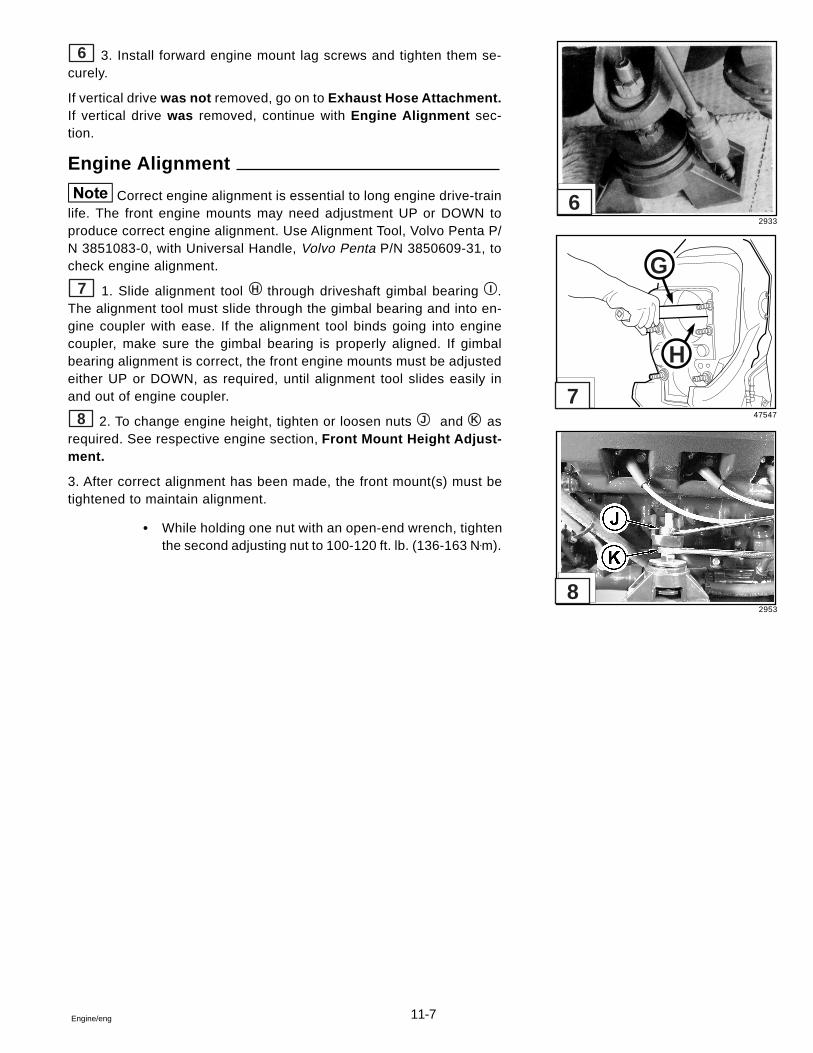
11-7Engine/eng
6 3. Install forward engine mount lag screws and tighten them se-curely.
If vertical drive was not removed, go on to Exhaust Hose Attachment.If vertical drive was removed, continue with Engine Alignment sec-tion.
Engine Alignment
Correct engine alignment is essential to long engine drive-trainlife. The front engine mounts may need adjustment UP or DOWN toproduce correct engine alignment. Use Alignment Tool, Volvo Penta P/N 3851083-0, with Universal Handle, Volvo Penta P/N 3850609-31, tocheck engine alignment.
7 1. Slide alignment tool H through driveshaft gimbal bearing I .The alignment tool must slide through the gimbal bearing and into en-gine coupler with ease. If the alignment tool binds going into enginecoupler, make sure the gimbal bearing is properly aligned. If gimbalbearing alignment is correct, the front engine mounts must be adjustedeither UP or DOWN, as required, until alignment tool slides easily inand out of engine coupler.
8 2. To change engine height, tighten or loosen nuts J and K asrequired. See respective engine section, Front Mount Height Adjust-ment.
3. After correct alignment has been made, the front mount(s) must betightened to maintain alignment.
• While holding one nut with an open-end wrench, tightenthe second adjusting nut to 100-120 ft. lb. (136-163 N•m).
2933
47547
2953
G
H
8
7
6
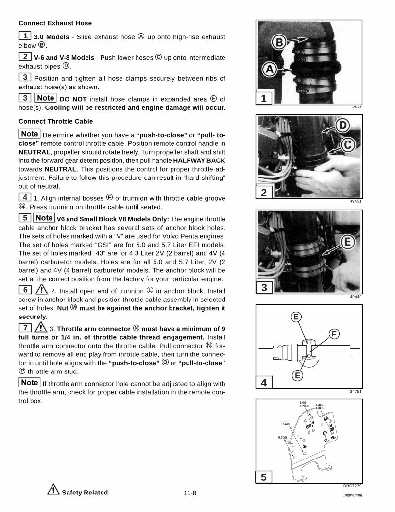
11-8 Engine/eng
Connect Exhaust Hose
1 3.0 Models - Slide exhaust hose A up onto high-rise exhaustelbow B .
2 V-6 and V-8 Models - Push lower hoses C up onto intermediateexhaust pipes D .
3 Position and tighten all hose clamps securely between ribs ofexhaust hose(s) as shown.
3 DO NOT install hose clamps in expanded area E ofhose(s). Cooling will be restricted and engine damage will occur.
Connect Throttle Cable
Determine whether you have a “push-to-close” or “pull- to-close” remote control throttle cable. Position remote control handle inNEUTRAL , propeller should rotate freely. Turn propeller shaft and shiftinto the forward gear detent position, then pull handle HALFWAY BACKtowards NEUTRAL . This positions the control for proper throttle ad-justment. Failure to follow this procedure can result in “hard shifting”out of neutral.
4 1. Align internal bosses F of trunnion with throttle cable grooveG . Press trunnion on throttle cable until seated.
5 V6 and Small Block V8 Models Only: The engine throttlecable anchor block bracket has several sets of anchor block holes.The sets of holes marked with a “V” are used for Volvo Penta engines.The set of holes marked “GSI” are for 5.0 and 5.7 Liter EFI models.The set of holes marked “43” are for 4.3 Liter 2V (2 barrel) and 4V (4barrel) carburetor models. Holes are for all 5.0 and 5.7 Liter, 2V (2barrel) and 4V (4 barrel) carburetor models. The anchor block will beset at the correct position from the factory for your particular engine.
6 2. Install open end of trunnion L in anchor block. Installscrew in anchor block and position throttle cable assembly in selectedset of holes. Nut M must be against the anchor bracket, tighten itsecurely.
7 3. Throttle arm connector N must have a minimum of 9full turns or 1/4 in. of throttle cable thread engagement. Installthrottle arm connector onto the throttle cable. Pull connector N for-ward to remove all end play from throttle cable, then turn the connec-tor in until hole aligns with the “push-to-close” O or “pull-to-close”P throttle arm stud.
If throttle arm connector hole cannot be adjusted to align withthe throttle arm, check for proper cable installation in the remote con-trol box.
Safety Related
2945
49451
49449
34751
DRC7279
E
E
F
5.7GS
5.0GL
4.3GL4.3GS
5.0Gi5.7GSi
5
4
3
2
1
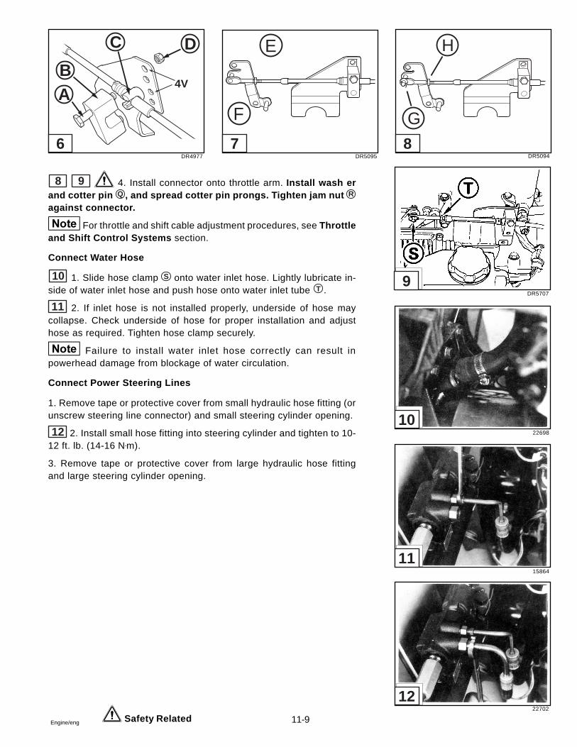
11-9Engine/eng
8 9 4. Install connector onto throttle arm. Install wash erand cotter pin Q , and spread cotter pin prongs. Tighten jam nut R
against connector.
For throttle and shift cable adjustment procedures, see Throttleand Shift Control Systems section.
Connect Water Hose
10 1. Slide hose clamp S onto water inlet hose. Lightly lubricate in-side of water inlet hose and push hose onto water inlet tube T .
11 2. If inlet hose is not installed properly, underside of hose maycollapse. Check underside of hose for proper installation and adjusthose as required. Tighten hose clamp securely.
Failure to install water inlet hose correctly can result inpowerhead damage from blockage of water circulation.
Connect Power Steering Lines
1. Remove tape or protective cover from small hydraulic hose fitting (orunscrew steering line connector) and small steering cylinder opening.
12 2. Install small hose fitting into steering cylinder and tighten to 10-12 ft. lb. (14-16 N•m).
3. Remove tape or protective cover from large hydraulic hose fittingand large steering cylinder opening.
Safety Related
DR4977 DR5095 DR5094
DR5707
22698
15864
22702
4V
DC
BA
E
F
H
G
6 7 8
9
10
11
12
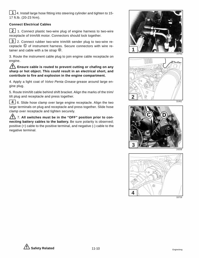
11-10 Engine/eng
1 4. Install large hose fitting into steering cylinder and tighten to 15-17 ft.lb. (20-23 N•m).
Connect Electrical Cables
2 1. Connect plastic two-wire plug of engine harness to two-wirereceptacle of trim/tilt motor. Connectors should lock together.
3 2. Connect rubber two-wire trim/tilt sender plug to two-wire re-ceptacle C of instrument harness. Secure connectors with wire re-tainer and cable with a tie strap D .
3. Route the instrument cable plug to join engine cable receptacle onengine.
Ensure cable is routed to prevent cutting or chafing on anysharp or hot object. This could result in an electrical short, andcontribute to fire and explosion in the engine compartment.
4. Apply a light coat of Volvo Penta Grease grease around large en-gine plug.
5. Route trim/tilt cable behind shift bracket. Align the marks of the trim/tilt plug and receptacle and press together.
4 6. Slide hose clamp over large engine receptacle. Align the twolarge terminals on plug and receptacle and press together. Slide hoseclamp over receptacle and tighten securely.
7. All switches must be in the “OFF” position prior to con-necting battery cables to the battery. Be sure polarity is observed;positive (+) cable to the positive terminal, and negative (-) cable to thenegative terminal.
Safety Related
22701
31461
24208
33729
4
3
2
1

11-11Engine/eng
Connect Fuel Supply
Attach boat’s fuel supply hose to fuel filter canister. On EFI modelsconnect to the MOAS. Tighten connection securely. Check for fuelleaks when testing engine, and repair any leaks that might occur.
Rear Engine Mounts
Removal
1. Remove engine as previously described in this section.
4 2. Unscrew two screws and washers, then lift mount assembly offtransom plate.
Disassembly
5 Hold square nut and remove screw. Mount assembly will breakdown into components shown. Pay particular attention to the two mountwashers; their thickness, shape (concave or flat), and position in theassembly (above or below the rubber mount).
Assembly
5 1. Slide lower washer F onto mount bolt; make sure you choosethe correct washer (as determined during the mount disassembly) forthisposition. Insert bolt into bottom (flat) side of rubber mount assembly,and install remaining washer and square nut. Do not tighten nut at thistime.
If top and bottom washers are not installed in their original po-sitions, mount may transmit excessive engine vibrations into boat andcause undesirable operating conditions.
6 2. Turn mount assembly upside down and clamp square nut invise. Rotate rubber mount until mounting holes are positioned at 90° toany side of square nut. Hold mount in this position and tighten centerbolt to 44-52 ft. lb. (60-71 N•m).
If 90° relationship between nut and mounting holes is not main-tained, slot of engine mount pad cannot engage rear mount during in-stallation.
Installation
7 1. Place mount assembly on transom plate. Install two screws andwashers, and tighten them to 20-25 ft. lb. (27-34 N•m).
8 2. Install engine as previously described in this section. Make suremount pad slot engages square nut. Install both flat washers and lock-nuts, then tighten locknuts to 28-30 ft. lb. (38-41 N•m).
6678
16348
6680
6677
12212
8
7
6
5
4
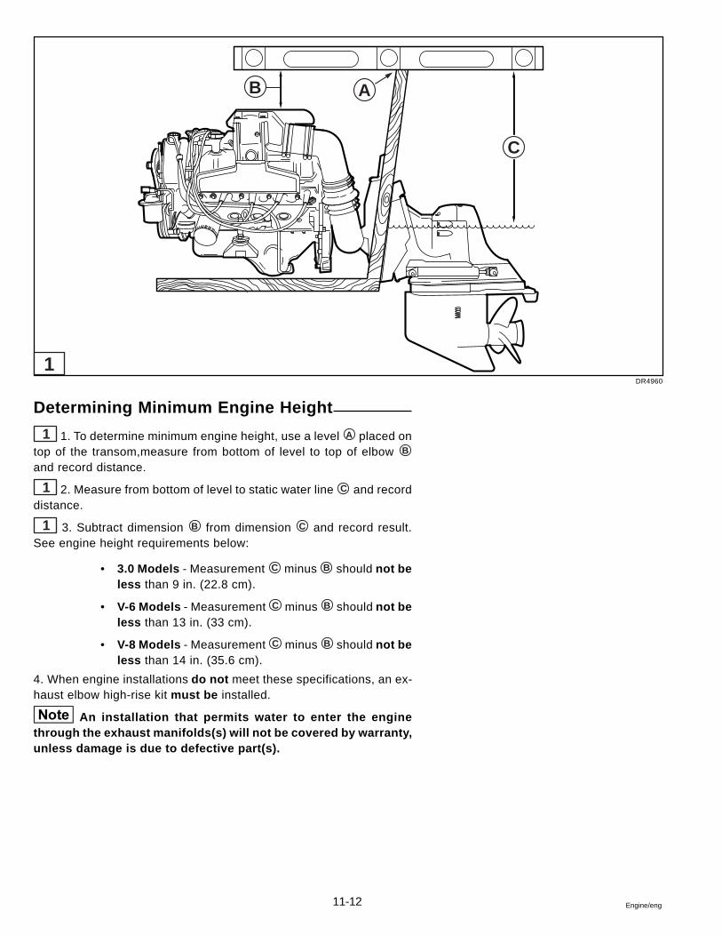
11-12 Engine/eng
Determining Minimum Engine Height
1 1. To determine minimum engine height, use a level A placed ontop of the transom,measure from bottom of level to top of elbow B
and record distance.
1 2. Measure from bottom of level to static water line C and recorddistance.
1 3. Subtract dimension B from dimension C and record result.See engine height requirements below:
• 3.0 Models - Measurement C minus B should not beless than 9 in. (22.8 cm).
• V-6 Models - Measurement C minus B should not beless than 13 in. (33 cm).
• V-8 Models - Measurement C minus B should not beless than 14 in. (35.6 cm).
4. When engine installations do not meet these specifications, an ex-haust elbow high-rise kit must be installed.
An installation that permits water to enter the enginethrough the exhaust manifolds(s) will not be covered by warranty,unless damage is due to defective part(s).
DR4960
AB
C
1
S-1Safety
Safety Section
Part A
Marine Products and Safety of People Who Use Them . . . . . . . . . S-2Sterndrive Shift System . . . . . . . . . . . . . . . . . . . . . . . . . . . . . . . . . S-3Sterndrive Throttle Control System . . . . . . . . . . . . . . . . . . . . . . . . S-4Sterndrive Steering System . . . . . . . . . . . . . . . . . . . . . . . . . . . . . . S-5Sterndrive Fuel, Electrical System . . . . . . . . . . . . . . . . . . . . . . . . . S-7
Part B
Marine Products and Safety of People Who Fix Them . . . . . . . . S-11Handling Engines . . . . . . . . . . . . . . . . . . . . . . . . . . . . . . . . . . . . . S-11Handling Lead Acid Batteries . . . . . . . . . . . . . . . . . . . . . . . . . . . . S-12Gasoline! Handle with Care . . . . . . . . . . . . . . . . . . . . . . . . . . . . . S-13Hazardous Products . . . . . . . . . . . . . . . . . . . . . . . . . . . . . . . . . . . S-14
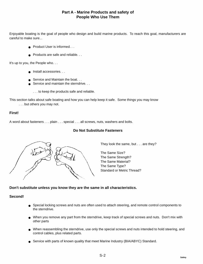
S-2Safety
Part A - Marine Products and safety ofPeople Who Use Them
Enjoyable boating is the goal of people who design and build marine products. To reach this goal, manufacturers arecareful to make sure...
Product User is informed. . .
Products are safe and reliable. . .
It's up to you, the People who. . .
Install accessories. . .
Service and Maintain the boat. . .Service and maintain the sterndrive. . .
. . . to keep the products safe and reliable.
This section talks about safe boating and how you can help keep it safe. Some things you may know. . . but others you may not.
First!
A word about fasteners . . . plain . . . special . . . all screws, nuts, washers and bolts.
Do Not Substitute Fasteners
Don't substitute unless you know they are the same in all characteristics.
Second!
Special locking screws and nuts are often used to attach steering, and remote control components tothe sterndrive.
When you remove any part from the sterndrive, keep track of special screws and nuts. Don't mix withother parts
When reassembling the sterndrive, use only the special screws and nuts intended to hold steering, andcontrol cables, plus related parts.
Service with parts of known quality that meet Marine Industry (BIA/ABYC) Standard.
They look the same, but . . . are they?
The Same Size?The Same Strength?The Same Material?The Same Type?Standard or Metric Thread?
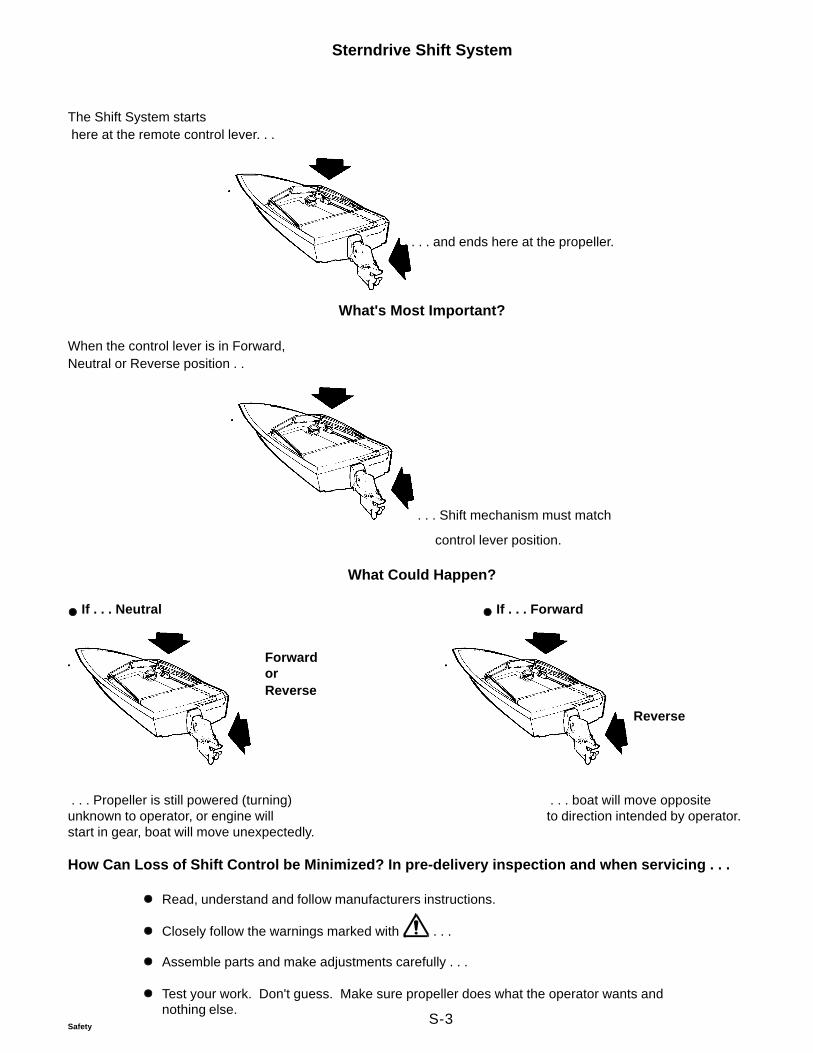
S-3Safety
Sterndrive Shift System
The Shift System starts here at the remote control lever. . .
. . . and ends here at the propeller.
What's Most Important?
When the control lever is in Forward,Neutral or Reverse position . .
. . . Shift mechanism must match
control lever position.
What Could Happen?
If . . . Neutral If . . . Forward
Reverse
. . . Propeller is still powered (turning) . . . boat will move oppositeunknown to operator, or engine will to direction intended by operator.start in gear, boat will move unexpectedly.
How Can Loss of Shift Control be Minimized? In pre-delivery inspection and when servicing . . .
Read, understand and follow manufacturers instructions.
Closely follow the warnings marked with . . .
Assemble parts and make adjustments carefully . . .
Test your work. Don't guess. Make sure propeller does what the operator wants andnothing else.
ForwardorReverse
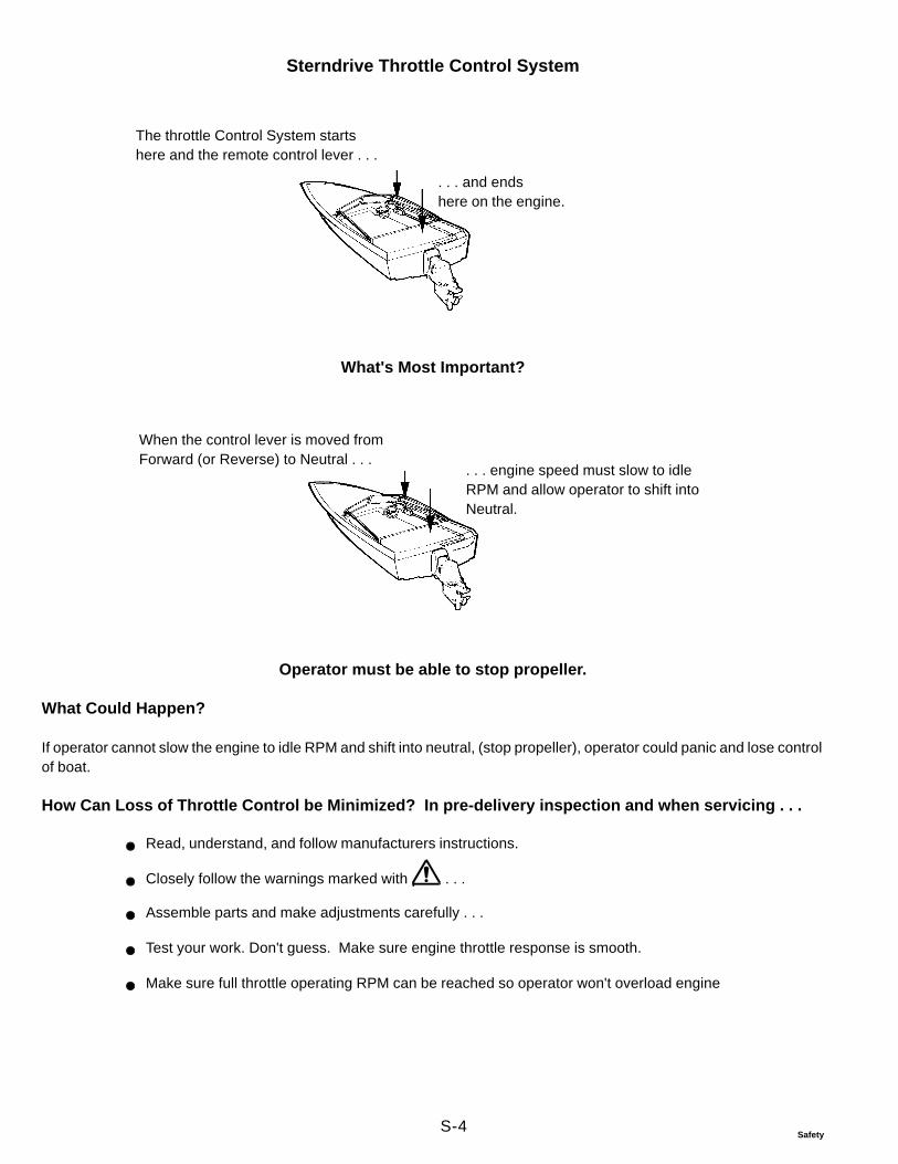
S-4Safety
Sterndrive Throttle Control System
. . . and endshere on the engine.
The throttle Control System startshere and the remote control lever . . .
What's Most Important?
When the control lever is moved fromForward (or Reverse) to Neutral . . .
. . . engine speed must slow to idleRPM and allow operator to shift intoNeutral.
Operator must be able to stop propeller.
What Could Happen?
If operator cannot slow the engine to idle RPM and shift into neutral, (stop propeller), operator could panic and lose controlof boat.
How Can Loss of Throttle Control be Minimized? In pre-delivery inspection and when servicing . . .
Read, understand, and follow manufacturers instructions.
Closely follow the warnings marked with . . .
Assemble parts and make adjustments carefully . . .
Test your work. Don't guess. Make sure engine throttle response is smooth.
Make sure full throttle operating RPM can be reached so operator won't overload engine
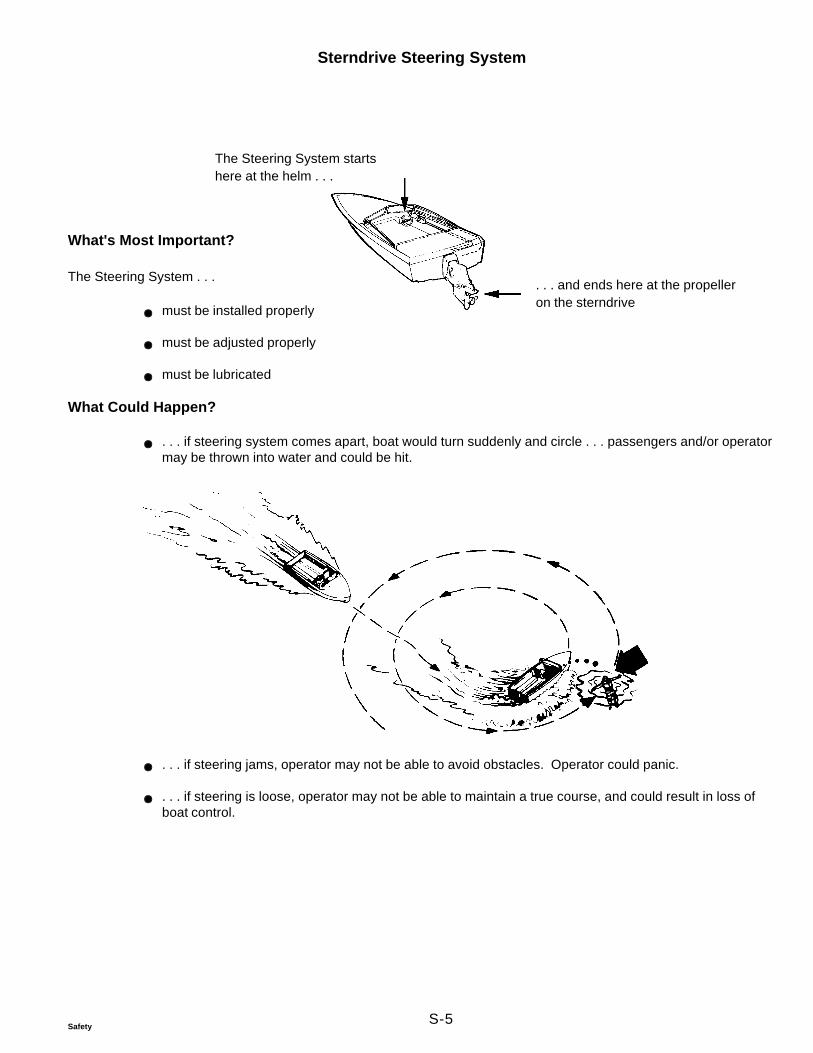
S-5Safety
Sterndrive Steering System
The Steering System startshere at the helm . . .
. . . and ends here at the propelleron the sterndrive
What's Most Important?
The Steering System . . .
must be installed properly
must be adjusted properly
must be lubricated
What Could Happen?
. . . if steering system comes apart, boat would turn suddenly and circle . . . passengers and/or operatormay be thrown into water and could be hit.
. . . if steering jams, operator may not be able to avoid obstacles. Operator could panic.
. . . if steering is loose, operator may not be able to maintain a true course, and could result in loss ofboat control.
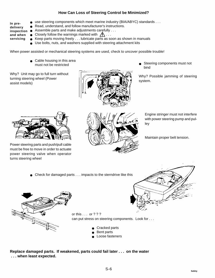
S-6Safety
How Can Loss of Steering Control be Minimized?
use steering components which meet marine industry (BIA/ABYC) standards . . .Read, understand, and follow manufacturer's instructions.Assemble parts and make adjustments carefully . . .Closely follow the warnings marked with . . .Keep parts moving freely . . . lubricate parts as soon as shown in manualsUse bolts, nuts, and washers supplied with steering attachment kits
When power assisted or mechanical steering systems are used, check to uncover possible trouble!
Cable housing in this areamust not be restricted
Why? Unit may go to full turn withoutturning steering wheel (Powerassist models)
Steering components must notbind
Why? Possible jamming of steeringsystem.
In pre-deliveryinspectionand whenservicing
Power steering parts and push/pull cablemust be free to move in order to actuatepower steering valve when operatorturns steering wheel
Engine stringer must not interferewith power steering pump and pul-ley
Maintain proper belt tension.
Check for damaged parts . . . impacts to the sterndrive like this
or this . . . or ? ? ?can put stress on steering components. Look for . . .
Cracked partsBent partsLoose fasteners
Replace damaged parts. If weakened, parts could fail later . . . on the water . . . when least expected.
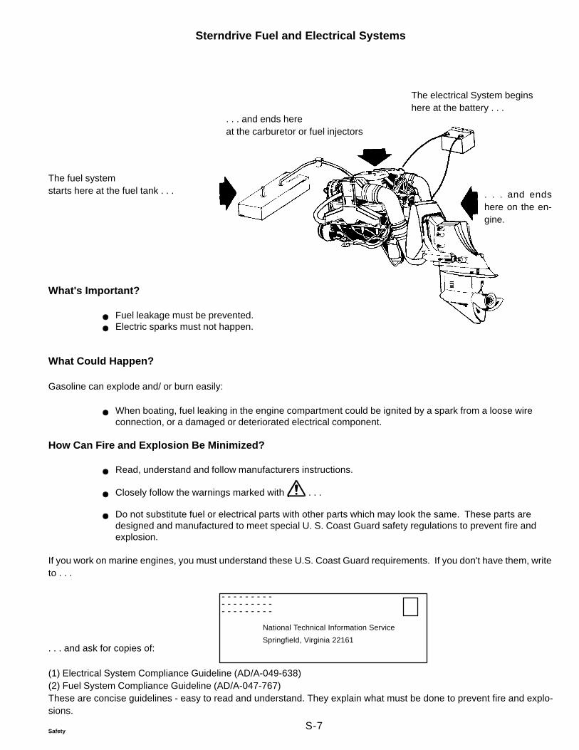
S-7Safety
Sterndrive Fuel and Electrical Systems
The electrical System beginshere at the battery . . .
The fuel systemstarts here at the fuel tank . . .
. . . and ends hereat the carburetor or fuel injectors
. . . and endshere on the en-gine.
What's Important?
Fuel leakage must be prevented.Electric sparks must not happen.
What Could Happen?
Gasoline can explode and/ or burn easily:
When boating, fuel leaking in the engine compartment could be ignited by a spark from a loose wireconnection, or a damaged or deteriorated electrical component.
How Can Fire and Explosion Be Minimized?
Read, understand and follow manufacturers instructions.
Closely follow the warnings marked with . . .
Do not substitute fuel or electrical parts with other parts which may look the same. These parts aredesigned and manufactured to meet special U. S. Coast Guard safety regulations to prevent fire andexplosion.
If you work on marine engines, you must understand these U.S. Coast Guard requirements. If you don't have them, writeto . . .
- - - - - - - - - - - - - - - - - - - - - - - - - - -
National Technical Information Service
Springfield, Virginia 22161. . . and ask for copies of:
(1) Electrical System Compliance Guideline (AD/A-049-638)(2) Fuel System Compliance Guideline (AD/A-047-767)These are concise guidelines - easy to read and understand. They explain what must be done to prevent fire and explo-sions.
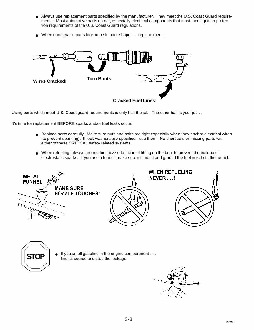
S-8Safety
Always use replacement parts specified by the manufacturer. They meet the U.S. Coast Guard require-ments. Most automotive parts do not, especially electrical components that must meet ignition protec-tion requirements of the U.S. Coast Guard regulations.
When nonmetallic parts look to be in poor shape . . . replace them!
Wires Cracked! Torn Boots!
Cracked Fuel Lines!
Using parts which meet U.S. Coast guard requirements is only half the job. The other half is your job . . .
It's time for replacement BEFORE sparks and/or fuel leaks occur.
Replace parts carefully. Make sure nuts and bolts are tight especially when they anchor electrical wires(to prevent sparking). If lock washers are specified - use them. No short cuts or missing parts witheither of these CRITICAL safety related systems.
When refueling, always ground fuel nozzle to the inlet fitting on the boat to prevent the buildup ofelectrostatic sparks. If you use a funnel, make sure it's metal and ground the fuel nozzle to the funnel.
STOP If you smell gasoline in the engine compartment . . .find its source and stop the leakage.
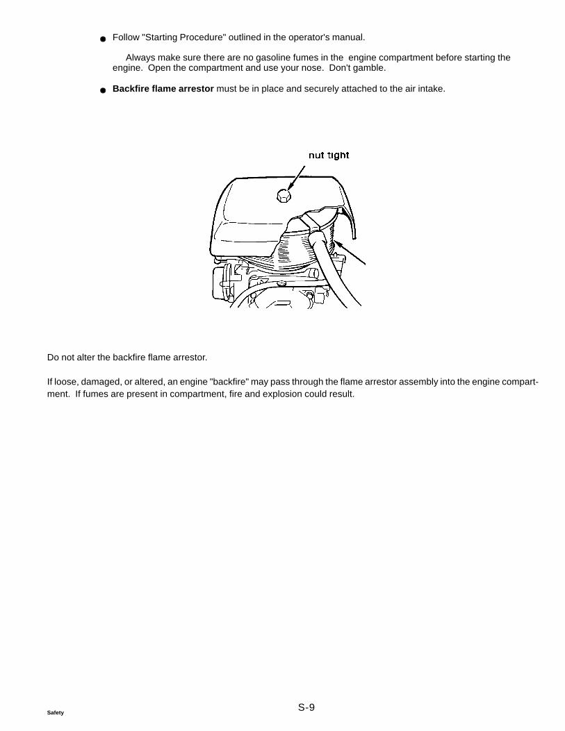
S-9Safety
Follow "Starting Procedure" outlined in the operator's manual.
Always make sure there are no gasoline fumes in the engine compartment before starting theengine. Open the compartment and use your nose. Don't gamble.
Backfire flame arrestor must be in place and securely attached to the air intake.
Do not alter the backfire flame arrestor.
If loose, damaged, or altered, an engine "backfire" may pass through the flame arrestor assembly into the engine compart-ment. If fumes are present in compartment, fire and explosion could result.
S-10Safety
Summing Up
Now you know some things that can take the joy out of enjoyable boating.
No doubt about it . . . it takes time!
Reading and understanding instructions.
Reading and understanding warnings marked with . . .
Putting parts together correctly . . .
Making correct adjustments . . .
Testing you work.
and making sure
Worn or damaged parts are replaced,
Replaced parts are like originals . . . in every way.
Customer is told of things which need attention . . .
But do you really want the alternative?
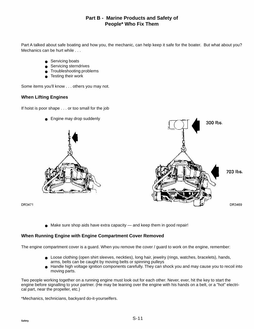
S-11Safety
Part B - Marine Products and Safety ofPeople* Who Fix Them
Part A talked about safe boating and how you, the mechanic, can help keep it safe for the boater. But what about you?Mechanics can be hurt while . . .
Servicing boatsServicing sterndrivesTroubleshooting problemsTesting their work
Some items you'll know . . . others you may not.
When Lifting Engines
If hoist is poor shape . . . or too small for the job
Engine may drop suddenly
Make sure shop aids have extra capacity — and keep them in good repair!
When Running Engine with Engine Compartment Cover Removed
The engine compartment cover is a guard. When you remove the cover / guard to work on the engine, remember:
Loose clothing (open shirt sleeves, neckties), long hair, jewelry (rings, watches, bracelets), hands,arms, belts can be caught by moving belts or spinning pulleysHandle high voltage ignition components carefully. They can shock you and may cause you to recoil intomoving parts.
Two people working together on a running engine must look out for each other. Never, ever, hit the key to start theengine before signalling to your partner. (He may be leaning over the engine with his hands on a belt, or a "hot" electri-cal part, near the propeller, etc.)
*Mechanics, technicians, backyard do-it-yourselfers.
DR3471 DR3469
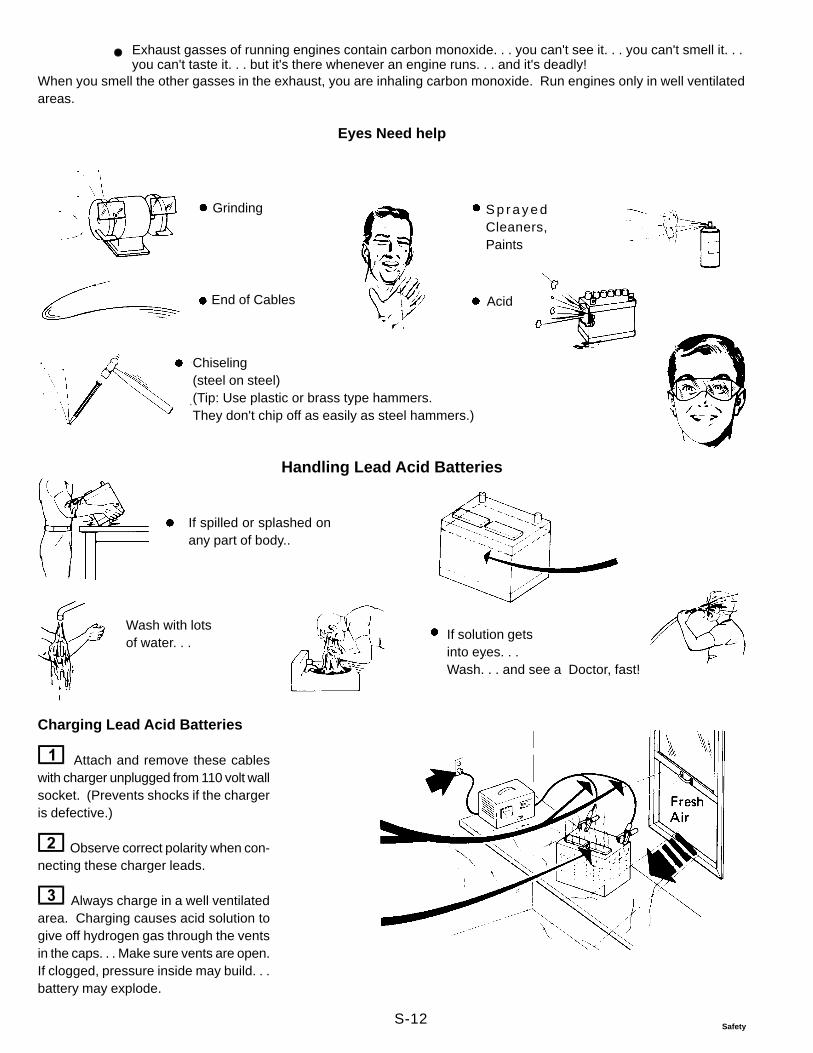
S-12Safety
Exhaust gasses of running engines contain carbon monoxide. . . you can't see it. . . you can't smell it. . .you can't taste it. . . but it's there whenever an engine runs. . . and it's deadly!
When you smell the other gasses in the exhaust, you are inhaling carbon monoxide. Run engines only in well ventilatedareas.
Eyes Need help
Grinding S p r a y e dCleaners,Paints
End of Cables Acid
Chiseling(steel on steel)(Tip: Use plastic or brass type hammers.They don't chip off as easily as steel hammers.)
If spilled or splashed onany part of body..
If solution getsinto eyes. . .Wash. . . and see a Doctor, fast!
Wash with lotsof water. . .
Charging Lead Acid Batteries
Attach and remove these cableswith charger unplugged from 110 volt wallsocket. (Prevents shocks if the chargeris defective.)
Observe correct polarity when con-necting these charger leads.
Always charge in a well ventilatedarea. Charging causes acid solution togive off hydrogen gas through the ventsin the caps. . . Make sure vents are open.If clogged, pressure inside may build. . .battery may explode.
Handling Lead Acid Batteries
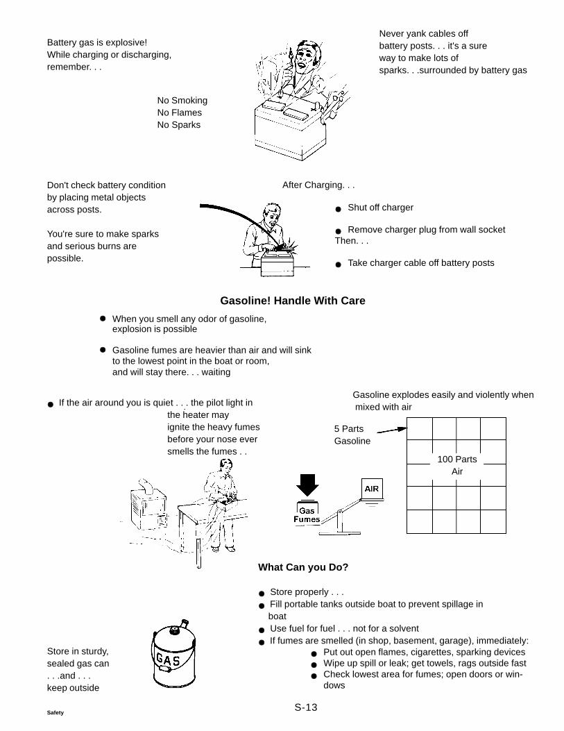
S-13Safety
Battery gas is explosive!While charging or discharging,remember. . .
Never yank cables offbattery posts. . . it's a sureway to make lots ofsparks. . .surrounded by battery gas
No SmokingNo FlamesNo Sparks
Don't check battery conditionby placing metal objectsacross posts.
You're sure to make sparksand serious burns arepossible.
After Charging. . .
Shut off charger
Remove charger plug from wall socketThen. . .
Take charger cable off battery posts
Gasoline explodes easily and violently when mixed with air
5 PartsGasoline
100 PartsAir
If the air around you is quiet . . . the pilot light inthe heater mayignite the heavy fumesbefore your nose eversmells the fumes . .
Gasoline! Handle With Care
When you smell any odor of gasoline,explosion is possible
Gasoline fumes are heavier than air and will sinkto the lowest point in the boat or room,and will stay there. . . waiting
Store in sturdy,sealed gas can. . .and . . .keep outside
What Can you Do?
Store properly . . . Fill portable tanks outside boat to prevent spillage in
boat Use fuel for fuel . . . not for a solvent If fumes are smelled (in shop, basement, garage), immediately:
Put out open flames, cigarettes, sparking devicesWipe up spill or leak; get towels, rags outside fastCheck lowest area for fumes; open doors or win-dows
S-14Safety
Read the container label. It tells you . . .
"How, and where, to use,""How to give First Aid," and have "recommended" first aid materials on hand- should anemergency arise"How to dispose of can,"
Remember: Little children are very curious and will try to taste everything, so . . .
. . . yummmmmmmmmmm Keep containers awayfrom children
Know items in and around repair area which can ignite gasoline fumes . . . Control them if fumes are smelled.
Matches, cigarettes, torches, weldersElectric motors (with unsealed cases)Electric generators (with unsealed cases)Light switchesAppliance pilot lights (furnace, dryer, water heater)?????????
How many of these are in your area?
Hazardous Products


Par
t No.
779
7353
© 1
999.
Vol
vo P
enta
of t
he A
mer
icas
, Inc
. P
rinte
d in
U.S
.A.
Volvo Penta of the Americas, Inc.
1300 Volvo Penta DriveChesapeake, Virginia 23320
U.S.A.
®