Embed Size (px)
Citation preview
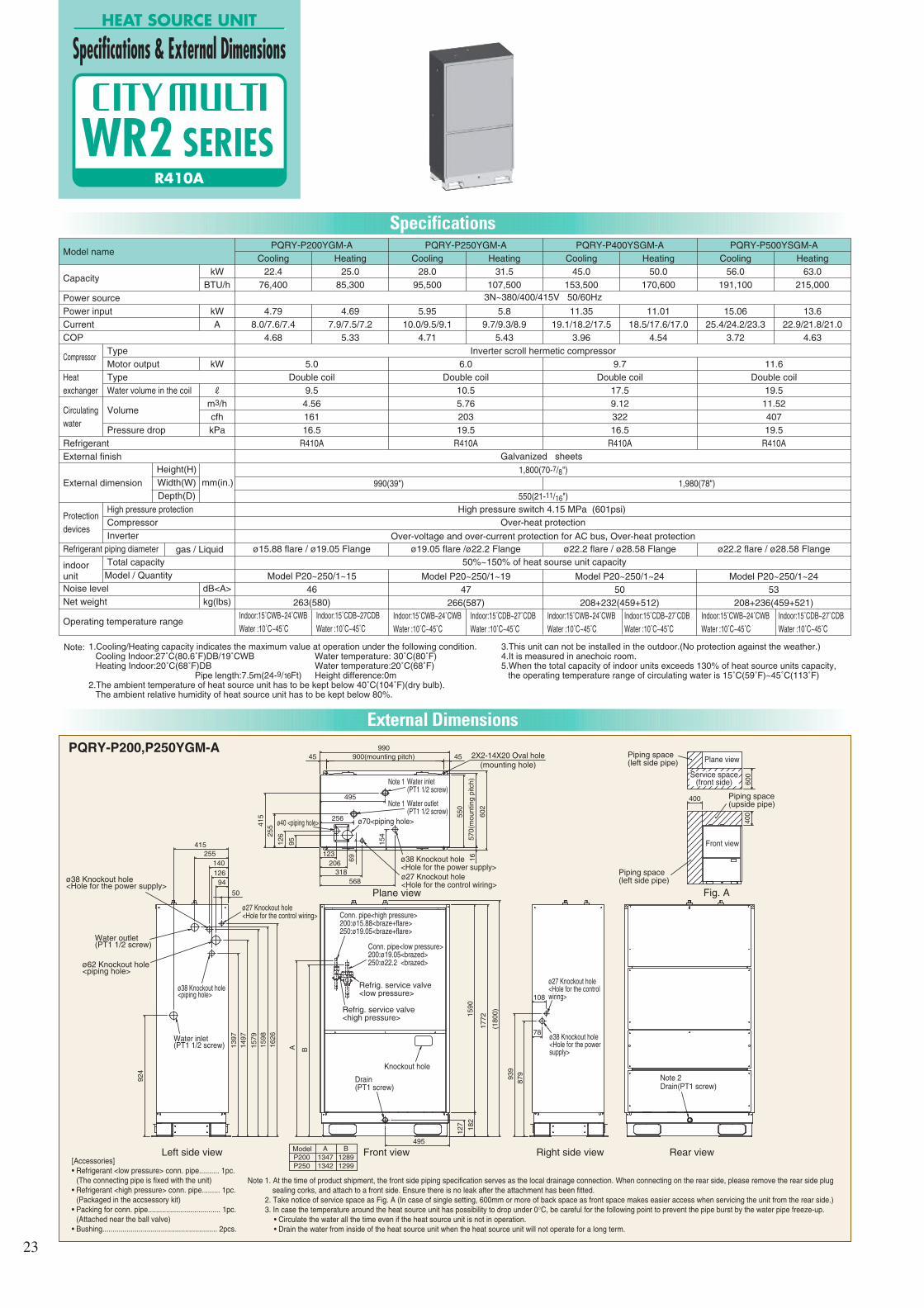
Specifications
3N~380/400/415V 50/60Hz
Inverter scroll hermetic compressor
High pressure switch 4.15 MPa (601psi)
Over-heat protection
50%~150% of heat sourse unit capacity
Over-voltage and over-current protection for AC bus, Over-heat protection
Galvanized sheets
External Dimensions
PQRY-P200,P250YGM-A
HEAT SOURCE UNIT
Specifications & External Dimensions
R410A
WR2 SERIES
Model name
Capacity
Power source
Power input
Current
COP
Type
Motor output
Type
Water volume in the coil
Volume
Pressure drop
Refrigerant
External finish
External dimension
High pressure protection
Compressor
Inverter
Refrigerant piping diameter
Total capacity
Model / Quantity
Noise level
Net weight
Operating temperature range
kW
BTU/h
kW
A
kW
R
m3/h
cfh
kPa
dB<A>
kg(lbs)
Compressor
Heat
exchanger
Circulating
water
Protection
devices
indoorunit
gas / Liquid
PQRY-P200YGM-A
Cooling
22.4
76,400
4.79
8.0/7.6/7.4
4.68
Heating
25.0
85,300
4.69
7.9/7.5/7.2
5.33
5.0
Double coil
9.5
4.56
161
16.5
R410A
ø15.88 flare / ø19.05 Flange
Indoor:15˚CWB~24˚CWB
Water :10˚C~45˚C
Indoor:15˚CDB~27CDB
Water :10˚C~45˚C
PQRY-P250YGM-A
Cooling
28.0
95,500
5.95
10.0/9.5/9.1
4.71
Heating
31.5
107,500
5.8
9.7/9.3/8.9
5.43
6.0
Double coil
10.5
5.76
203
19.5
R410A
ø19.05 flare /ø22.2 Flange
Indoor:15˚CWB~24˚CWB
Water :10˚C~45˚C
Indoor:15˚CDB~27˚CDB
Water :10˚C~45˚C
PQRY-P400YSGM-A
Cooling
45.0
153,500
11.35
19.1/18.2/17.5
3.96
Heating
50.0
170,600
11.01
18.5/17.6/17.0
4.54
9.7
Double coil
17.5
9.12
322
16.5
R410A
ø22.2 flare / ø28.58 Flange
Indoor:15˚CWB~24˚CWB
Water :10˚C~45˚C
Indoor:15˚CDB~27˚CDB
Water :10˚C~45˚C
PQRY-P500YSGM-A
Cooling
56.0
191,100
15.06
25.4/24.2/23.3
3.72
Heating
63.0
215,000
13.6
22.9/21.8/21.0
4.63
11.6
Double coil
19.5
11.52
407
19.5
R410A
ø22.2 flare / ø28.58 Flange
Indoor:15˚CWB~24˚CWB
Water :10˚C~45˚C
Indoor:15˚CDB~27˚CDB
Water :10˚C~45˚C
Model P20~250/1~15
46
263(580)
Model P20~250/1~19
47
266(587)
Model P20~250/1~24
50
208+232(459+512)
Model P20~250/1~24
53
208+236(459+521)
Height(H)
Width(W)
Depth(D)
1,800(70-7/8")
550(21-11/16")
990(39") 1,980(78")
1.Cooling/Heating capacity indicates the maximum value at operation under the following condition.Cooling Indoor:27˚C(80.6˚F)DB/19˚CWB Water temperature: 30˚C(80˚F)Heating Indoor:20˚C(68˚F)DB Water temperature:20˚C(68˚F)
Pipe length:7.5m(24-9/16Ft) Height difference:0m2.The ambient temperature of heat source unit has to be kept below 40˚C(104˚F)(dry bulb).
The ambient relative humidity of heat source unit has to be kept below 80%.
Note: 3.This unit can not be installed in the outdoor.(No protection against the weather.)4.It is measured in anechoic room.5.When the total capacity of indoor units exceeds 130% of heat source units capacity,
the operating temperature range of circulating water is 15˚C(59˚F)~45˚C(113˚F)
mm(in.)
400
400
60
0
(18
00
)
A B
95
12
6
15
90
17
72
16
15
79
140
126
415
255
94
50
41
5
25
5
15
4
69
93
9
87
9
18
2
568
495
318
12
7
256
206
123
990
45 45900(mounting pitch)
60
2
57
0(m
ou
ntin
g p
itch
)
55
0
16
26
15
98
14
97
92
4
13
97 78
108
495
Left side view Front view Right side view Rear view
Plane view
[Accessories]• Refrigerant <low pressure> conn. pipe.......... 1pc.
(The connecting pipe is fixed with the unit)• Refrigerant <high pressure> conn. pipe......... 1pc.
(Packaged in the accsessory kit)• Packing for conn. pipe.................................... 1pc.
(Attached near the ball valve)• Bushing......................................................... 2pcs.
Note 1. At the time of product shipment, the front side piping specification serves as the local drainage connection. When connecting on the rear side, please remove the rear side plug sealing corks, and attach to a front side. Ensure there is no leak after the attachment has been fitted.
2. Take notice of service space as Fig. A (In case of single setting, 600mm or more of back space as front space makes easier access when servicing the unit from the rear side.)3. In case the temperature around the heat source unit has possibility to drop under 0°C, be careful for the following point to prevent the pipe burst by the water pipe freeze-up.
• Circulate the water all the time even if the heat source unit is not in operation.• Drain the water from inside of the heat source unit when the heat source unit will not operate for a long term.
2X2-14X20 Oval hole(mounting hole)
Water inlet(PT1 1/2 screw)
Note 1
Water outlet(PT1 1/2 screw)
Note 1
ø70<piping hole>ø40 <piping hole>
ø38 Knockout hole<Hole for the power supply>ø27 Knockout hole<Hole for the control wiring>
Piping space(left side pipe)
Piping space(left side pipe)
Piping space(upside pipe)
Fig. A
Plane view
Front view
Service space(front side)
ø38 Knockout hole<Hole for the power supply>
ø62 Knockout hole<piping hole>
Water outlet(PT1 1/2 screw)
ø38 Knockout hole<piping hole>
Water inlet(PT1 1/2 screw)
ø27 Knockout hole<Hole for the control wiring>
P250 1299
1289
B
P200
A
1347
1342
Model
Conn. pipe<high pressure>200:ø15.88<braze+flare>250:ø19.05<braze+flare>
Conn. pipe<low pressure>200:ø19.05<brazed>250:ø22.2 <brazed>
Refrig. service valve<low pressure>
Refrig. service valve<high pressure>
Knockout hole
Drain(PT1 screw)
ø38 Knockout hole<Hole for the power supply>
ø27 Knockout hole<Hole for the control wiring>
Drain(PT1 screw)Note 2
23

External Dimensions
PQRY-P400,P500YSGM-A
HEAT SOURCE UNIT
Specifications & External Dimensions
R410A
WR2 SERIES
400
60
04
00
233
143
12
65
85
1990
10990
64
8
13
176
719
126
418
272
16
60
2
570(
mou
ntin
g pi
tch)
55
0
15
90
12
7
18
2
17
72
41
8
27
245900(mounting pitch)
990
66
0
15
99
95
0
69
15
4
568
318
93
9
87
9
45 900(mounting pitch)
78
108
ø70<piping hole>
2X2-14X20 Oval hole2X2-14X20 Oval hole
(18
00
)
ø56<piping hole>
(mounting hole)(mounting hole)
Fig. A
Front view
Piping space(left side pipe)
Piping space(upside pipe)
Piping space(left side pipe)
Plane view
Service space(front side)
ø38 Knockout hole<Hole for the power supply>
ø27 Knockout hole<Hole for the control wiring>
Water inlet(PT2 screw)
Water outlet(PT2 screw)
Water outlet(PT2 screw)
Water inlet(PT2 screw)
Plane view
Knockout hole<piping hole>
Left side view
Conn. pipe<low pressure>ø28.58<brazed>
Conn. pipe<high pressure>ø22.2<brazed>
Locally pipingø9.52 <braze+flare>ø19.05 <braze+flare>ø25.4 <flange,brazed>
Conn.pipe between HEX unit and Compressor unit (Extension code for water heat source)Control signal wire <connector,locally connected>
ø27 Knockout hole<Hole for the control wiring>
ø38 Knockout hole<Hole for the power supply>
Compressor unit
Front view Right side view
Heat exchanger unit
Refrig. service valve<high pressure>
Refrig. service valve<low pressure>
Knockout hole
Drain(PT1 screw)
Drain(PT1 screw)
[Accessories]• Refrigerant conn.pipe....................................................... 2pcs.
(The connecting pipe is fixed with the unit)• Refrigerant conn.pipe between HEX unit and Compressor unit
ø9.52................................................................................ 2pcs.(Packaged in the accessory kit)ø19.05.............................................................................. 2pcs.(Packaged in the accessory kit)ø25.4................................................................................ 2pcs.(Packaged in the accessory kit : HEX unit)(The connecting pipe is fixed with the unit : Compressor unit)
• Packing for conn.pipe....................................................... 4pcs.(Attached near the ball valve)
• Bushing............................................................................ 2pcs.• Extension code for water heat source............................... 1set
Note 1. At the time of product shipment, the front side piping specification serves as the local drainage connection. When connecting on the rear side, please remove the rear side plug sealing corks, and attach to a front side. Ensure there is no leak after the attachment has been fitted.
2. Take notice of service space as Fig. A (In case of single setting, 600mm or more of back space as front space makes easier access when servicing the unit from the rear side.)3. In case the temperature around the heat source unit has possibility to drop under 0°C, be careful for the following point to prevent the pipe burst by the water pipe freeze-up.
• Circulate the water all the time even if the heat source unit is not in operation.• Drain the water from inside of the heat source unit when the heat source unit will not operate for a long term.
4. Use the extension code for water heat source (option) to take space (more than 2m) between HEX unit and Compressor unit.
24