Embed Size (px)
Citation preview
W.S. Graves DESY-Zeuthen 8/2003
1
Study for an xray Study for an xray
laser at MIT Bates laser at MIT Bates
LaboratoryLaboratoryWilliam S. Graves
MIT-Bates
Presented at ICFA S2E workshopDESY-Zeuthen
August, 2003
mitbates.mit.edu/xfel contains text of proposal to
NSF

W.S. Graves DESY-Zeuthen 8/2003
2
Design TeamDesign Team
Principal Investigator
David E. Moncton
Science Accelerator
James Fujimoto Franz X. Kaertner Manouchehr Farkhondeh
Hermann Haus Richard Milner William M. Fawley
Erich Ippen Simon Mochrie William S. Graves
Ian McNulty Keith A. Nelson Christoph Tschalaer
Denis B. McWhan Gregory Petsko Jan Van der Laan
Jianwei Miao Dagmar Ringe Fuhua Wang
Michael Pellin Andrei Tokmakoff Abbi Zolfaghari
Marc Schattenburg
Townsend Zwart
W.S. Graves DESY-Zeuthen 8/2003
3
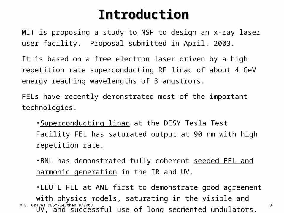
IntroductionIntroductionMIT is proposing a study to NSF to design an x-ray laser user
facility. Proposal submitted in April, 2003.
It is based on a free electron laser driven by a high repetition rate
superconducting RF linac of about 4 GeV energy reaching
wavelengths of 3 angstroms.
FELs have recently demonstrated most of the important
technologies.
•Superconducting linac at the DESY Tesla Test Facility FEL has
saturated output at 90 nm with high repetition rate.
•BNL has demonstrated fully coherent seeded FEL and
harmonic generation in the IR and UV.
•LEUTL FEL at ANL first to demonstrate good agreement with
physics models, saturating in the visible and UV, and
successful use of long segmented undulators.

W.S. Graves DESY-Zeuthen 8/2003
4
Study ProposalStudy Proposal
•3 year study leading into to construction of a multi-beamline user
facility
•5 beamlines already proposed + 4 additional concepts
•Study will fund groups to design 10 beamlines. User program
committee (A. Bienenstock, chair) met in July to discuss user program
and beamline solicitation process.
•Scientific workshop planning underway.
•Accelerator advisory committee to meet in September to review
initial concept.
•Develop laser, accelerator, and beamline designs to level of
Conceptual Design Report in first half of study, detailed design and
prototype R&D in second half.
•Significant education and project management initiatives in
proposal.

W.S. Graves DESY-Zeuthen 8/2003
5
• Plan 10 (of a possible 30) beamlines in construction project
• “Principal users” will lead beamline development
• Peer Review process will select Principal Users
• Plan to integrate Principal Users in project team
• Include initial (10) beamline costs in project budget
• Include beamline operations in facility operating budget
• Question #1: What is “the deal” for Principal Users?
• Question #2: What is the selection process?
User programUser program
W.S. Graves DESY-Zeuthen 8/2003
6
• MIT has embraced the x-ray laser concept for the future of Bates Laboratory
• The existing 80-acre parcel of land and its existing infrastructure will be made available
• MIT will fund a series of early scientific workshops across the relevant fields
• MIT will empanel and support distinguished advisory committees to guide the science, and technology, as well as user program development and project management
• MIT is committing funds to hire additional project staff in the immediate future in technology areas such as x-ray optics/beamline design
• MIT Center for Materials Science and Engineering (Physics Dept) provides administration
MIT CommitmentMIT Commitment
W.S. Graves DESY-Zeuthen 8/2003
7
Facility conceptFacility concept
•Laser output from FEL is closely coupled with seed and
pump/probe lasers.
•Use mature technologies: TESLA SRF linac, long segmented
undulators, seeded and SASE operation.
•Three undulator halls: UV, nanometer, and x-ray.
•Three ebeam energies: 1, 2, and 4 GeV to drive the respective
halls.
•3-7 undulator beamlines per hall: total beamlines 10-20.
•Accelerator repetition rate 10 – 20 kHz: ~1 kHz per beamline to
match conventional lasers.
•Low average current (~1 A) with high average flux.
•Preserve future upgrade to 1 angstrom with improvements in
accelerator and undulator technology.
W.S. Graves DESY-Zeuthen 8/2003
8
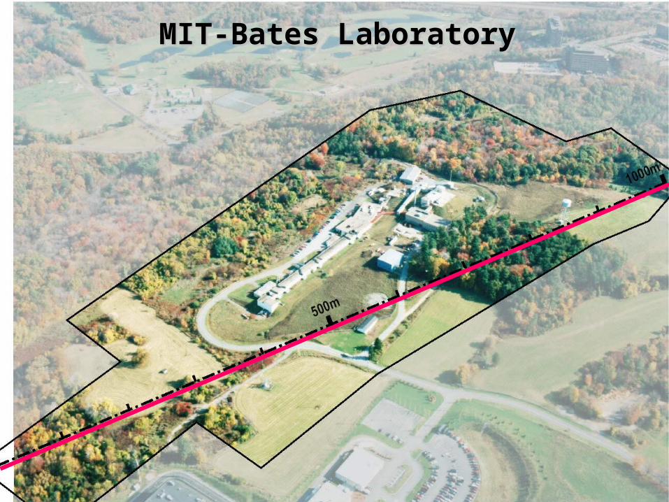
MIT-Bates LaboratoryMIT-Bates Laboratory
W.S. Graves DESY-Zeuthen 8/2003
9
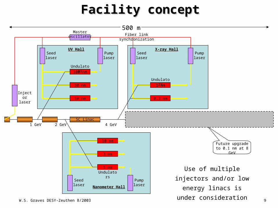
Facility conceptFacility concept
0.3 nm 0.1 nm
UV Hall X-ray Hall
Nanometer Hall
SC Linac4 GeV2 GeV1 GeV
1 nm
0.3 nm
100 nm
30 nm
10 nm
10 nm
3 nm
1 nm
Master oscillator
Pump laser
Pump laser
Seed laser
Seed laser
Seed laser
Pump laser
Fiber link synchronization
Injector laser
Undulators
Undulators
Undulators
Future upgrade to 0.1 nm at 8 GeV
SC Linac
Use of multiple injectors
and/or low energy linacs
is under consideration
500 m
W.S. Graves DESY-Zeuthen 8/2003
10
1
10
100
1000
0 5 10 15 20
Electron Energy (GeV)
Sa
tura
tio
n L
en
gth
(m
)
2X M
$
3X M
$
4X M
$
5X M
$100 nm
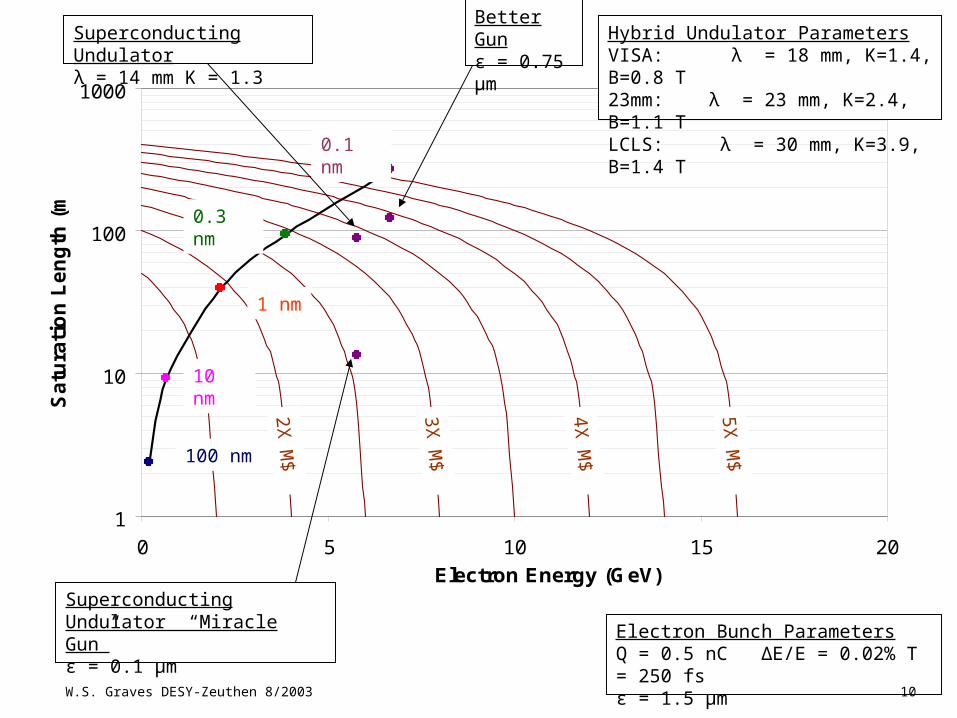
Electron Bunch ParametersQ = 0.5 nC ΔE/E = 0.02% T = 250 fsε = 1.5 μm
Hybrid Undulator ParametersVISA: λ = 18 mm, K=1.4, B=0.8 T23mm: λ = 23 mm, K=2.4, B=1.1 TLCLS: λ = 30 mm, K=3.9, B=1.4 T
10 nm
1 nm
0.3 nm
0.1 nm
Better Gunε = 0.75 μmSuperconducting Undulator
λ = 14 mm K = 1.3
Superconducting Undulator “Miracle Gun”ε = 0.1 μm
W.S. Graves DESY-Zeuthen 8/2003
11
Electron beam performanceElectron beam performance
0.2 0.4 0.6 0.8 1 1.2 1.41
1.5
2
2.5
3
Pea
k cu
rren
t (kA
)
40 50
60 70 80 90 100
110
120
0.2 0.4 0.6 0.8 1 1.2 1.41
1.5
2
2.5
3
Norm. emittance (um)
Pea
k cu
rren
t (kA
)
40 50
60 70 80 90 100
110
120
0.2 0.4 0.6 0.8 1 1.2 1.4
1
1.5
2
2.5
3
3.5
4
4.5
5
dE/E
(x1
.0e -4
)
40 50 60 70 80 90 100110
120
0.2 0.4 0.6 0.8 1 1.2 1.4
1
1.5
2
2.5
3
3.5
4
4.5
5
0.2 0.4 0.6 0.8 1 1.2 1.4
1
1.5
2
2.5
3
3.5
4
4.5
5
Norm. emittance (m)dE
/E (
.01%
)
40 50 60 70 80 90
100110
120
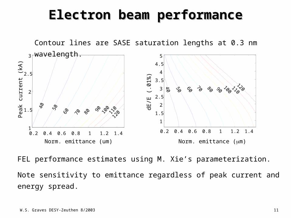
FEL performance estimates using M. Xie’s parameterization.
Note sensitivity to emittance regardless of peak current and energy
spread.
Contour lines are SASE saturation lengths at 0.3 nm
wavelength.
W.S. Graves DESY-Zeuthen 8/2003
12
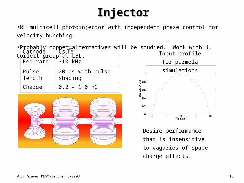
InjectorInjector•RF multicell photoinjector with independent phase control for velocity
bunching.
•Probably copper…alternatives will be studied. Work with J. Corlett group at
LBL.Cathode Cs2Te
Rep rate ~10 kHz
Pulse length 20 ps with pulse shaping
Charge 0.2 – 1.0 nC
-10 -5 0 5 100
0.2
0.4
0.6
0.8
1
Time (ps)
Inte
nsity
(A.U
.)
-10 -5 0 5 100
0.2
0.4
0.6
0.8
1
Time (ps)
Inte
nsity
(A.U
.)
Desire performance that
is insensitive to vagaries
of space charge effects.
Input profile for
parmela
simulations
W.S. Graves DESY-Zeuthen 8/2003
13
-10 -5 0 5 107.5
7.6
7.7
7.8
7.9
8
Time (ps)
K.E
. (M
eV)
-10 -5 0 5 100
2
4
6
8
Time (ps)
Cur
rent
(A
)
-10 -5 0 5 100.5
1
1.5
2
Time (ps)
dE(k
eV)
7.5
7.6
7.7
7.8
7.9
8
0 500 1000 1500
Ene
rgy
(MeV
)
Counts
7.5
7.6
7.7
7.8
7.9
8
0 1000 2000 3000
Ene
rgy
(MeV
)
Counts
-10 -5 0 5 100
2
4
6
Time (ps)
dE(k
eV)
-10 -5 0 5 100
10
20
30
40
Time (ps)
Cur
rent
(A
)
-10 -5 0 5 107.5
7.6
7.7
7.8
7.9
8
Time (ps)
K.E
. (M
eV)
7.5
7.6
7.7
7.8
7.9
8
0 1000 2000 3000 4000
Ene
rgy
(MeV
)
Counts
-10 -5 0 5 100
2
4
6
8
10
Time (ps)
dE(k
eV)
-10 -5 0 5 100
20
40
60
80
Time (ps)
Cur
rent
(A
)
-10 -5 0 5 107.5
7.6
7.7
7.8
7.9
8
Time (ps)
K.E
. (M
eV)
0.1 nC 0.5 nC 1 nC
-10 -5 0 5 107.5
7.6
7.7
7.8
7.9
8
Time (ps)
K.E
. (M
eV)
-10 -5 0 5 100
2
4
6
8
Time (ps)
Cur
rent
(A
)
-10 -5 0 5 100.5
1
1.5
2
Time (ps)
dE(k
eV)
7.5
7.6
7.7
7.8
7.9
8
0 500 1000 1500
Ene
rgy
(MeV
)
Counts
7.5
7.6
7.7
7.8
7.9
8
0 1000 2000 3000
Ene
rgy
(MeV
)
Counts
-10 -5 0 5 100
2
4
6
Time (ps)
dE(k
eV)
-10 -5 0 5 100
10
20
30
40
Time (ps)
Cur
rent
(A
)
-10 -5 0 5 107.5
7.6
7.7
7.8
7.9
8
Time (ps)
K.E
. (M
eV)
7.5
7.6
7.7
7.8
7.9
8
0 1000 2000 3000 4000
Ene
rgy
(MeV
)
Counts
-10 -5 0 5 100
2
4
6
8
10
Time (ps)
dE(k
eV)
-10 -5 0 5 100
20
40
60
80
Time (ps)
Cur
rent
(A
)
-10 -5 0 5 107.5
7.6
7.7
7.8
7.9
8
Time (ps)
K.E
. (M
eV)
-10 -5 0 5 107.5
7.6
7.7
7.8
7.9
8
Time (ps)
K.E
. (M
eV)
-10 -5 0 5 100
2
4
6
8
Time (ps)
Cur
rent
(A
)
-10 -5 0 5 100.5
1
1.5
2
Time (ps)
dE(k
eV)
7.5
7.6
7.7
7.8
7.9
8
0 500 1000 1500
Ene
rgy
(MeV
)
Counts
-10 -5 0 5 107.5
7.6
7.7
7.8
7.9
8
Time (ps)
K.E
. (M
eV)
-10 -5 0 5 107.5
7.6
7.7
7.8
7.9
8
Time (ps)
K.E
. (M
eV)
-10 -5 0 5 100
2
4
6
8
Time (ps)
Cur
rent
(A
)-10 -5 0 5 10
0
2
4
6
8
Time (ps)
Cur
rent
(A
)
-10 -5 0 5 100.5
1
1.5
2
Time (ps)
dE(k
eV)
-10 -5 0 5 100.5
1
1.5
2
Time (ps)
dE(k
eV)
7.5
7.6
7.7
7.8
7.9
8
0 500 1000 1500
Ene
rgy
(MeV
)
Counts
7.5
7.6
7.7
7.8
7.9
8
0 500 1000 1500
Ene
rgy
(MeV
)
Counts
7.5
7.6
7.7
7.8
7.9
8
0 1000 2000 3000
Ene
rgy
(MeV
)
Counts
-10 -5 0 5 100
2
4
6
Time (ps)
dE(k
eV)
-10 -5 0 5 100
10
20
30
40
Time (ps)
Cur
rent
(A
)
-10 -5 0 5 107.5
7.6
7.7
7.8
7.9
8
Time (ps)
K.E
. (M
eV)
7.5
7.6
7.7
7.8
7.9
8
0 1000 2000 3000
Ene
rgy
(MeV
)
Counts
7.5
7.6
7.7
7.8
7.9
8
0 1000 2000 3000
Ene
rgy
(MeV
)
Counts
-10 -5 0 5 100
2
4
6
Time (ps)
dE(k
eV)
-10 -5 0 5 100
2
4
6
Time (ps)
dE(k
eV)
-10 -5 0 5 100
10
20
30
40
Time (ps)
Cur
rent
(A
)
-10 -5 0 5 100
10
20
30
40
Time (ps)
Cur
rent
(A
)
-10 -5 0 5 107.5
7.6
7.7
7.8
7.9
8
Time (ps)
K.E
. (M
eV)
-10 -5 0 5 107.5
7.6
7.7
7.8
7.9
8
Time (ps)
K.E
. (M
eV)
7.5
7.6
7.7
7.8
7.9
8
0 1000 2000 3000 4000
Ene
rgy
(MeV
)
Counts
-10 -5 0 5 100
2
4
6
8
10
Time (ps)
dE(k
eV)
-10 -5 0 5 100
20
40
60
80
Time (ps)
Cur
rent
(A
)
-10 -5 0 5 107.5
7.6
7.7
7.8
7.9
8
Time (ps)
K.E
. (M
eV)
7.5
7.6
7.7
7.8
7.9
8
0 1000 2000 3000 4000
Ene
rgy
(MeV
)
Counts
7.5
7.6
7.7
7.8
7.9
8
0 1000 2000 3000 4000
Ene
rgy
(MeV
)
Counts
-10 -5 0 5 100
2
4
6
8
10
Time (ps)
dE(k
eV)
-10 -5 0 5 100
2
4
6
8
10
Time (ps)
dE(k
eV)
-10 -5 0 5 100
20
40
60
80
Time (ps)
Cur
rent
(A
)
-10 -5 0 5 100
20
40
60
80
Time (ps)
Cur
rent
(A
)
-10 -5 0 5 107.5
7.6
7.7
7.8
7.9
8
Time (ps)
K.E
. (M
eV)
-10 -5 0 5 107.5
7.6
7.7
7.8
7.9
8
Time (ps)
K.E
. (M
eV)
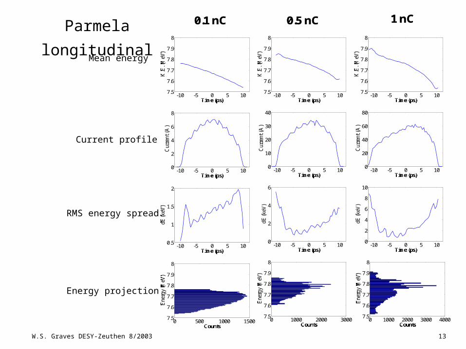
0.1 nC 0.5 nC 1 nC
Mean energy
Current profile
RMS energy spread
Energy projection
Parmela longitudinal
W.S. Graves DESY-Zeuthen 8/2003
14
-10 -5 0 5 100
10
20
30
40
50
Time (ps)
beta
X(m
)
-10 -5 0 5 100
10
20
30
40
50
Time (ps)
beta
X(m
)
-10 -5 0 5 10-15
-10
-5
0
Time (ps)
alph
aX
-10 -5 0 5 10-15
-10
-5
0
Time (ps)
alph
aX
-10 -5 0 5 100.2
0.3
0.4
0.5
Time (ps)
Em
itnx
(um
)
-10 -5 0 5 100.2
0.3
0.4
0.5
Time (ps)
Em
itnx
(um
)
-10 -5 0 5 100
20
40
60
80
100
Time (ps)
beta
X(m
)
-10 -5 0 5 100
20
40
60
80
100
Time (ps)
beta
X(m
)
-10 -5 0 5 10-40
-30
-20
-10
0
Time (ps)al
phaX
-10 -5 0 5 10-40
-30
-20
-10
0
Time (ps)al
phaX
-10 -5 0 5 100.2
0.3
0.4
0.5
Time (ps)
Em
itnx
(um
)
-10 -5 0 5 100.2
0.3
0.4
0.5
Time (ps)
Em
itnx
(um
)
-10 -5 0 5 100
50
100
150
Time (ps)
beta
X(m
)
-10 -5 0 5 100
50
100
150
Time (ps)
beta
X(m
)
-10 -5 0 5 10-50
-40
-30
-20
-10
0
Time (ps)
alph
aX
-10 -5 0 5 10-50
-40
-30
-20
-10
0
Time (ps)
alph
aX
-10 -5 0 5 100.2
0.3
0.4
0.5
Time (ps)
Em
itnx
(um
)
-10 -5 0 5 100.2
0.3
0.4
0.5
Time (ps)
Em
itnx
(um
)
0.1 nC 0.5 nC 1 nC
Time (ps) Time (ps)Time (ps)
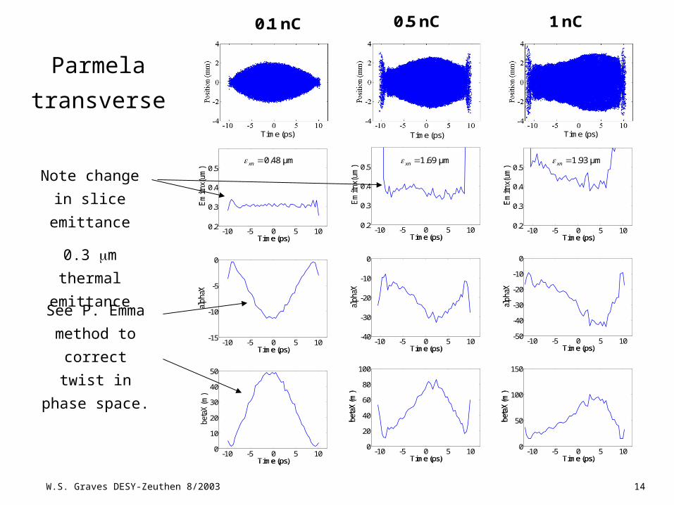
0.48 μmxn 1.69 μmxn 1.93 μmxn
Note change
in slice
emittance
0.3 m
thermal
emittanceSee P. Emma
method to
correct twist
in phase
space.
Parmela
transverse
W.S. Graves DESY-Zeuthen 8/2003
15
LinacLinac
•TESLA-type SRF linac.
•Prefer CW for stability and timing flexibility, but cost is issue.
•Two chicanes for bunch compression, limit total R56 and other
bends for precise timing control and small CSR effects.
•Fast ebeam switches to select beamlines at kHz rate, could
be ferrite or RF deflectors.
W.S. Graves DESY-Zeuthen 8/2003
16
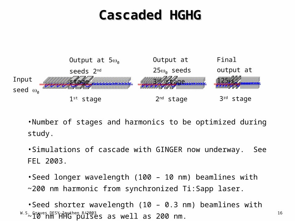
Cascaded HGHGCascaded HGHG
Input
seed 0
1st stage 2nd stage 3rd stage
Output at 50
seeds 2nd stage
Output at
250 seeds 3rd
stage
Final
output at
1250
•Number of stages and harmonics to be optimized during study.
•Simulations of cascade with GINGER now underway. See FEL
2003.
•Seed longer wavelength (100 – 10 nm) beamlines with ~200 nm
harmonic from synchronized Ti:Sapp laser.
•Seed shorter wavelength (10 – 0.3 nm) beamlines with ~10 nm
HHG pulses as well as 200 nm.
W.S. Graves DESY-Zeuthen 8/2003
17
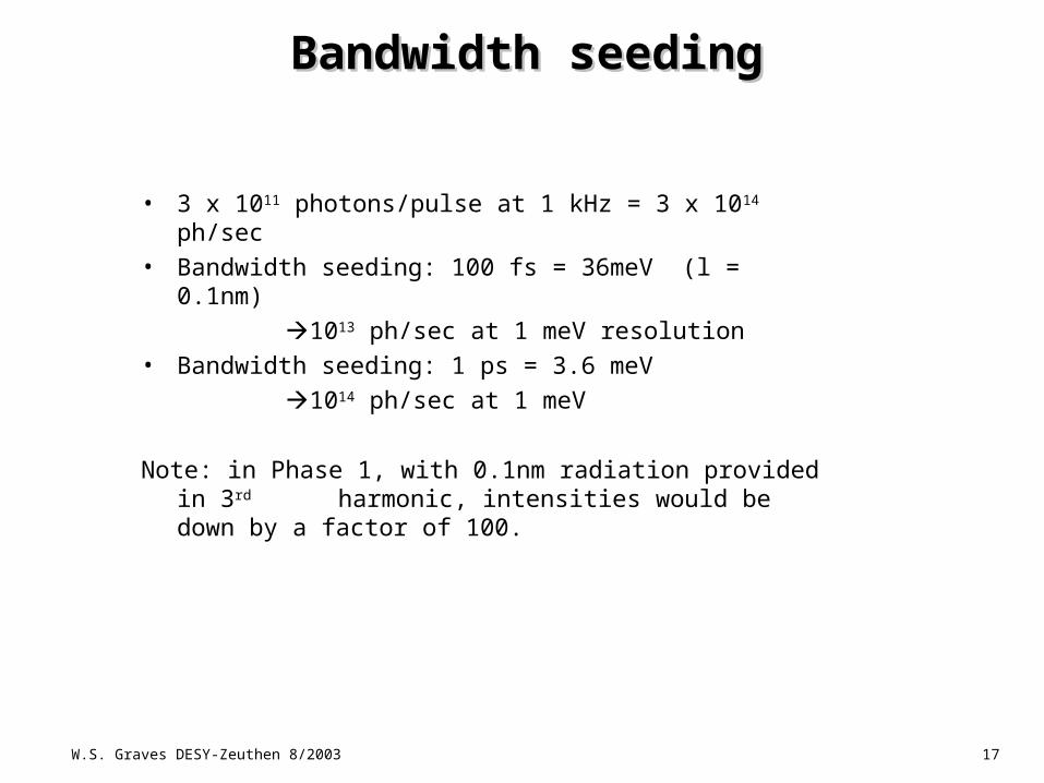
• 3 x 10¹¹ photons/pulse at 1 kHz = 3 x 10¹⁴ ph/sec• Bandwidth seeding: 100 fs = 36meV (l = 0.1nm) 1013 ph/sec at 1 meV resolution• Bandwidth seeding: 1 ps = 3.6 meV 1014 ph/sec at 1 meV
Note: in Phase 1, with 0.1nm radiation provided in 3rd harmonic, intensities would be down by a factor of 100.
Bandwidth seedingBandwidth seeding
W.S. Graves DESY-Zeuthen 8/2003
18
0 10 20 30 40 500
0.5
1
1.5
2
Time (fs)
Pow
er (
GW
)
0 10 20 30 40 500
0.5
1
1.5
2
Time (fs)
Pow
er (
GW
)
0 10 20 30 40 500
0.5
1
1.5
2
Time (fs)
Pow
er (
GW
)
0 10 20 30 40 500
0.5
1
1.5
2
Time (fs)
Pow
er (
GW
)
0 10 20 30 40 500
1
2
3
4
5
6
7
8
Time (fs)
Pow
er (
GW
)
0 10 20 30 40 500
1
2
3
4
5
6
7
8
Time (fs)
Pow
er (
GW
)
0.2995 0.3 0.3005 0.3010
200
400
600
800
1000
Wavelength (nm)
Pow
er (
kW/b
in)
0.2995 0.3 0.3005 0.3010
200
400
600
800
1000
Wavelength (nm)
Pow
er (
kW/b
in)
0.2995 0.3 0.3005 0.3010
100
200
300
400
500
Wavelength (nm)
Pow
er (
MW
/bin
)
0.2995 0.3 0.3005 0.3010
100
200
300
400
500
Wavelength (nm)
Pow
er (
MW
/bin
)
0.2995 0.3 0.3005 0.3010
100
200
300
400
500
Wavelength (nm)
Pow
er (
kW/b
in)
0.2995 0.3 0.3005 0.3010
100
200
300
400
500
Wavelength (nm)
Pow
er (
kW/b
in)
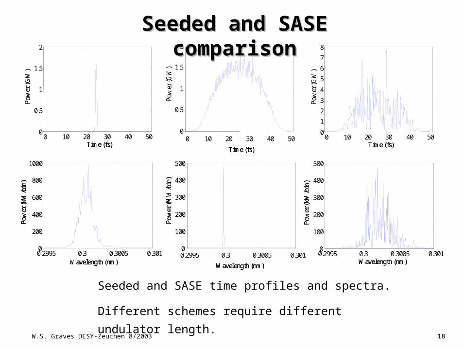
Seeded and SASE comparisonSeeded and SASE comparison
Seeded and SASE time profiles and spectra.
Different schemes require different undulator
length.
W.S. Graves DESY-Zeuthen 8/2003
19
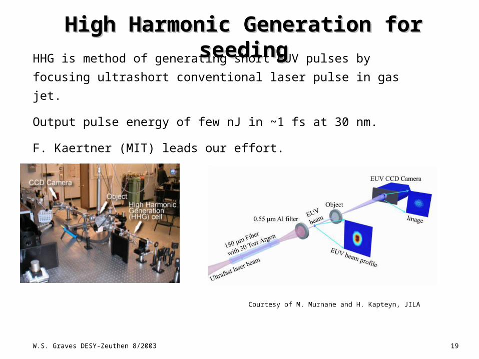
High Harmonic Generation for seedingHigh Harmonic Generation for seeding
Courtesy of M. Murnane and H. Kapteyn, JILA
HHG is method of generating short EUV pulses by focusing
ultrashort conventional laser pulse in gas jet.
Output pulse energy of few nJ in ~1 fs at 30 nm.
F. Kaertner (MIT) leads our effort.
W.S. Graves DESY-Zeuthen 8/2003
20
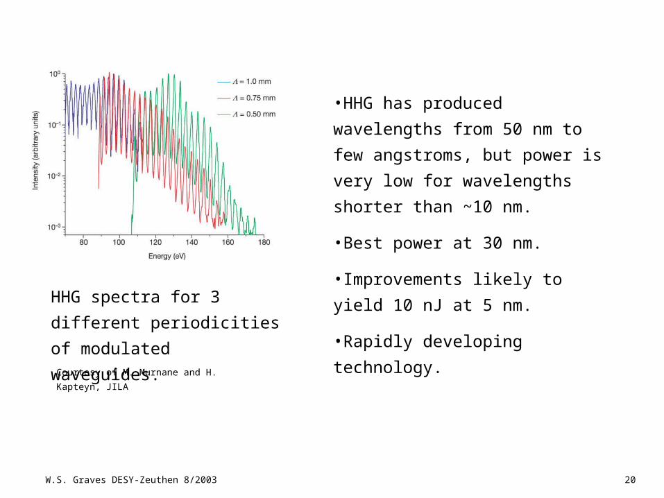
HHG spectra for 3 different
periodicities of modulated
waveguides.Courtesy of M. Murnane and H. Kapteyn, JILA
•HHG has produced wavelengths
from 50 nm to few angstroms,
but power is very low for
wavelengths shorter than ~10
nm.
•Best power at 30 nm.
•Improvements likely to yield 10
nJ at 5 nm.
•Rapidly developing technology.
W.S. Graves DESY-Zeuthen 8/2003
21
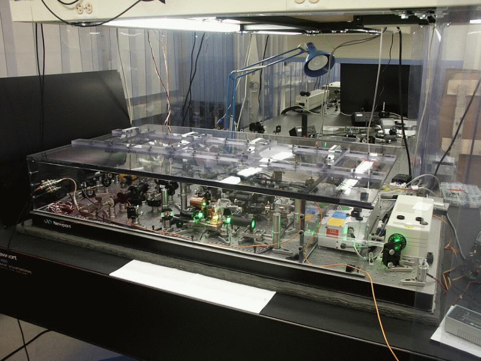
Femtosecond synchronizationFemtosecond synchronization
•Goal is to synchronize multiple lasers and electron beam to level of 10 fs.
•MIT has locked multiple independent lasers together with sub-fs accuracy
using optical heterodyne detector (balanced cross correlator).
•Optical clock signals delivered over several hundred meter fiberoptic have
been stabilized at ~10 fs level using active monitoring and control of fiber
length.
W.S. Graves DESY-Zeuthen 8/2003
22
W.S. Graves DESY-Zeuthen 8/2003
23
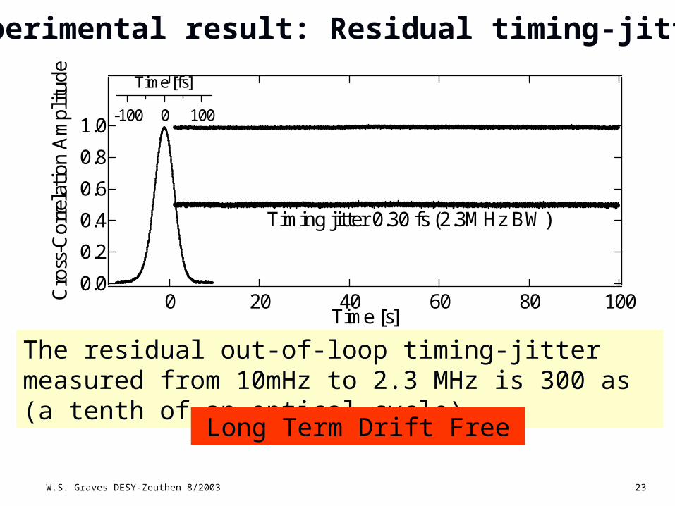
Experimental result: Residual timing-jitter
The residual out-of-loop timing-jitter measured from 10mHz to 2.3 MHz is 300 as (a tenth of an optical cycle)
Long Term Drift Free
1.0
0.8
0.6
0.4
0.2
0.0Cro
ss-C
orre
lati
on A
mpl
itud
e
-100 0 100
Time [fs]
100806040200Time [s]
Timing jitter 0.30 fs (2.3MHz BW)
W.S. Graves DESY-Zeuthen 8/2003
24
•Several technologies have reached sufficient maturity to enable design
of an x-ray laser user facility.
•Superconducting linac with photocathode gun allows high repetition
rate beamlines.
•Users expected to be integral part of design team. The performance of
all the facility’s lasers is critical.
•Much of the study activity will be addressed to endstation/beamline
design. Experiments will be part of integral to the construction proposal.
•Stability in energy and timing is critical to success.