Embed Size (px)
Citation preview
WSUD Reference Guidelines
2015

Hornsby Council WSUD Reference Guidance ii
Table of Contents
1. Hornsby Shire Council DCP 1C.1.2 Stormwater Management Requirements .................. 1
1.1 Erosion and Sediment Control ................................................................................. 1
1.2 Water Hydrology and Onsite Stormwater Management Plan .................................... 1
1.3 Water Quality........................................................................................................... 2
2. General information on WSUD Strategy preparation ....................................................... 1
2.1 WSUD Strategy ....................................................................................................... 1
2.2 Developments requiring a WSUD Strategy............................................................... 1
2.3 Developments requiring a Deemed to Comply Solution ............................................ 1
2.4 Other requirements.................................................................................................. 2
2.5 Supporting Information for the preparation of a WSUD Strategy ............................... 5
2.6 Further Information beyond the Development Application stage ............................... 5
2.7 Engaging a Consultant to develop a WSUD Strategy ............................................... 6
3. MUSIC Modelling Parameters for Hornsby...................................................................... 7
3.1 Rainfall & evaporation inputs ................................................................................... 7
3.2 Source node inputs.................................................................................................. 8
3.2.1 Rainfall runoff parameters................................................................................. 8
3.2.2 Pollutant generation parameters ..................................................................... 10
3.3 Treatment node inputs ........................................................................................... 12
4. Bioretention Systems as WSUD Treatment................................................................... 15
4.1 Elements of a Bioretention System ........................................................................ 16
4.2 Detailed design guidance....................................................................................... 17
4.3 Construction and Maintenance .............................................................................. 17
4.4 Requirement for a Management Plan for Issue of a Construction Certificate........... 18
5. Applicant Lodgement Checklist for WSUD Strategy ...................................................... 19
6. Case Study – Industrial................................................................................................. 20
6.1 Sizing Stormwater Treatment Systems .................................................................. 21
6.2 Prepare Design Drawings of Stormwater Treatment Systems ................................ 22
7. Case Study – High Density Residential ......................................................................... 23
7.1 Water Conservation Measures ............................................................................... 23
7.2 Sizing Stormwater Treatment Systems .................................................................. 23
7.3 Prepare Design Drawings of Stormwater Treatment Systems ................................ 24
8. References................................................................................................................... 25
9. Appendices .................................................................................................................. 26
9.1 Appendix A: Erosion and Sediment Control Plan ................................................... 26
Hornsby Council WSUD Reference Guidance 1
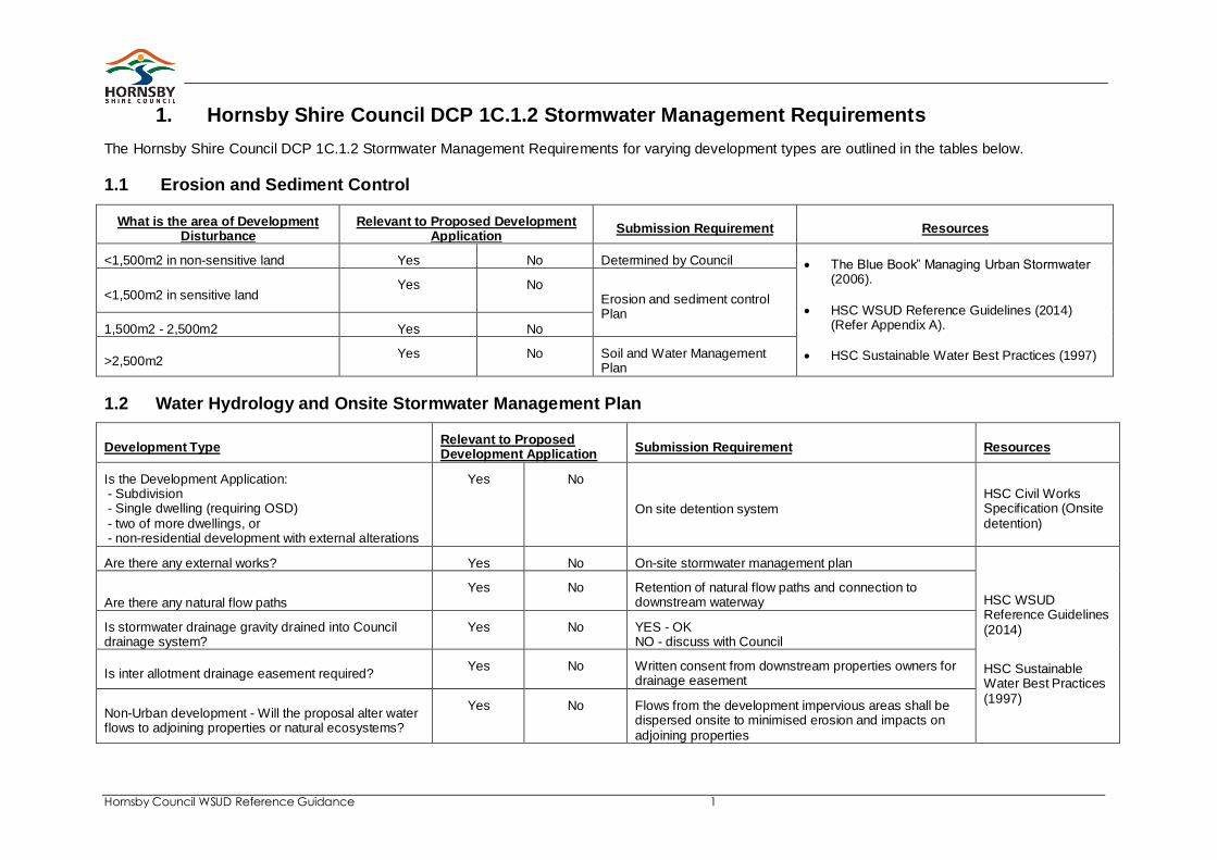
1. Hornsby Shire Council DCP 1C.1.2 Stormwater Management Requirements
The Hornsby Shire Council DCP 1C.1.2 Stormwater Management Requirements for varying development types are outlined in the tables below.
1.1 Erosion and Sediment Control
What is the area of Development Disturbance
Relevant to Proposed Development Application
Submission Requirement Resources
<1,500m2 in non-sensitive land Yes No Determined by Council The Blue Book” Managing Urban Stormwater (2006).
HSC WSUD Reference Guidelines (2014) (Refer Appendix A).
HSC Sustainable Water Best Practices (1997)
<1,500m2 in sensitive land Yes No
Erosion and sediment control Plan
1,500m2 - 2,500m2 Yes No
>2,500m2 Yes No Soil and Water Management
Plan
1.2 Water Hydrology and Onsite Stormwater Management Plan
Development Type Relevant to Proposed Development Application
Submission Requirement Resources
Is the Development Application: - Subdivision - Single dwelling (requiring OSD) - two of more dwellings, or - non-residential development with external alterations
Yes No
On site detention system HSC Civil Works Specification (Onsite detention)
Are there any external works? Yes No On-site stormwater management plan
HSC WSUD Reference Guidelines (2014)
HSC Sustainable Water Best Practices (1997)
Are there any natural flow paths Yes No Retention of natural flow paths and connection to
downstream waterway
Is stormwater drainage gravity drained into Council drainage system?
Yes No YES - OK NO - discuss with Council
Is inter allotment drainage easement required? Yes No Written consent from downstream properties owners for
drainage easement
Non-Urban development - Will the proposal alter water flows to adjoining properties or natural ecosystems?
Yes No Flows from the development impervious areas shall be dispersed onsite to minimised erosion and impacts on adjoining properties
Hornsby Council WSUD Reference Guidance 2
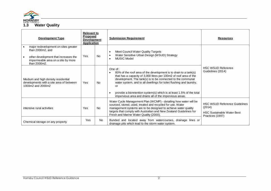
1.3 Water Quality
Development Type
Relevant to Proposed Development Application
Submission Requirement Resources
major redevelopment on sites greater than 2000m2, and
other development that increases the impermeable area on a site by more than 2000m2.
Yes No
Meet Council Water Quality Targets
Water Sensitive Urban Design (WSUD) Strategy MUSIC Model
HSC WSUD Reference Guidelines (2014)
Medium and high density residential developments with a site area of between 1000m2 and 2000m2
Yes No
One of: 80% of the roof area of the development is to drain to a tank(s)
that has a capacity of 3,000 litres per 100m2 of roof area of the development. The tank(s) is to be connected to the communal water system, and to all dwellings for toilet flushing and laundry, or
provide a bioretention system(s) which is at least 1.5% of the total impervious area and drains all of the impervious areas.
intensive rural activities Yes No
Water Cycle Management Plan (WCMP) - detailing how water will be sourced, stored, used, treated and recycled for use. Water management systems are to be designed to achieve water quality targets that comply with Australian and New Zealand Guidelines for Fresh and Marine Water Quality (2000).
HSC WSUD Reference Guidelines (2014)
HSC Sustainable Water Best Practices (1997)
Chemical storage on any property Yes No Bunded and located away from watercourses, drainage lines or
drainage pits which lead to the storm water system.
Hornsby Council WSUD Reference Guidance 1
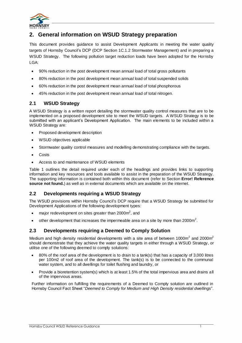
2. General information on WSUD Strategy preparation
This document provides guidance to assist Development Applicants in meeting the water quality
targets of Hornsby Council’s DCP (DCP Section 1C.1.2 Stormwater Management) and in preparing a
WSUD Strategy. The following pollution target reduction loads have been adopted for the Hornsby
LGA:
90% reduction in the post development mean annual load of total gross pollutants
80% reduction in the post development mean annual load of total suspended solids
60% reduction in the post development mean annual load of total phosphorous
45% reduction in the post development mean annual load of total nitrogen.
2.1 WSUD Strategy
A WSUD Strategy is a written report detailing the stormwater quality control measures that are to be implemented on a proposed development site to meet the WSUD targets. A WSUD Strategy is to be submitted with an applicant’s Development Application. The main elements to be included within a WSUD Strategy are:
Proposed development description
WSUD objectives applicable
Stormwater quality control measures and modelling demonstrating compliance with the targets.
Costs
Access to and maintenance of WSUD elements
Table 1 outlines the detail required under each of the headings and provides links to supporting information and key resources and tools available to assist in the preparation of the WSUD Strategy. The supporting information is contained both within this document (refer to Section Error! Reference source not found.) as well as in external documents which are available on the internet.
2.2 Developments requiring a WSUD Strategy
The WSUD provisions within Hornsby Council’s DCP require that a WSUD Strategy be submitted for Development Applications of the following development types:
major redevelopment on sites greater than 2000m2, and
other development that increases the impermeable area on a site by more than 2000m2.
2.3 Developments requiring a Deemed to Comply Solution
Medium and high density residential developments with a site area of between 1000m2 and 2000m
2
should demonstrate that they achieve the water quality targets in either through a WSUD Strategy, or utilise one of the following deemed to comply solutions:
80% of the roof area of the development is to drain to a tank(s) that has a capacity of 3,000 litres per 100m2 of roof area of the development. The tank(s) is to be connected to the communal water system, and to all dwellings for toilet flushing and laundry, or
Provide a bioretention system(s) which is at least 1.5% of the total impervious area and drains all of the impervious areas.
Further information on fulfilling the requirements of a Deemed to Comply solution are outlined in Hornsby Council Fact Sheet “Deemed to Comply for Medium and High Density residential dwellings”.

Hornsby Council WSUD Reference Guidance 2
2.4 Other requirements
In non-urban areas, intensive rural activities should include water management systems that are designed to achieve water quality targets that comply with Australian and New Zealand Guidelines for Fresh and Marine Water Quality (2000).
Chemical storage should be bunded and located away from watercourses, drainage lines or drainage pits which lead to the storm water system.
Hornsby Council WSUD Reference Guidance 3
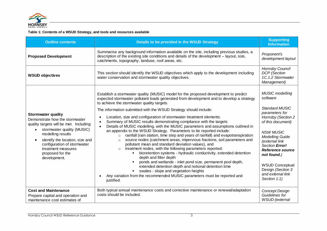
Table 1: Contents of a WSUD Strategy, and tools and resources available
Outline contents Details to be provided in the WSUD Strategy Supporting Information
Proposed Development Summarise any background information available on the site, including previous studies, a description of the existing site conditions and details of the development – layout, size, catchments, topography, landuse, roof areas, etc.
Proponent’s development layout
WSUD objectives This section should identify the WSUD objectives which apply to the development including water conservation and stormwater quality objectives.
Hornsby Council DCP (Section 1C.1.2 Stormwater
Management)
Stormwater quality
Demonstrate how the stormwater
quality targets will be met. Including:
stormwater quality (MUSIC) modelling results
identify the location, size and configuration of stormwater treatment measures proposed for the
development.
Establish a stormwater quality (MUSIC) model for the proposed development to predict expected stormwater pollutant loads generated from development and to develop a strategy to achieve the stormwater quality targets.
The information submitted with the WSUD Strategy should include:
Location, size and configuration of stormwater treatment elements.
Summary of MUSIC results demonstrating compliance with the targets
Details of MUSIC modelling, with the MUSIC parameters and assumptions outlined in an appendix to the WSUD Strategy. Parameters to be reported include:
o rainfall (rain station, time step and years of rainfall) and evapotranspiration o source nodes (catchment areas, impervious fractions, soil parameters and
pollutant mean and standard deviation values), and o treatment nodes, with the following parameters reported:
bioretention systems - hydraulic conductivity, extended detention depth and filter depth
ponds and wetlands - inlet pond size, permanent pool depth, extended detention depth and notional detention time
swales - slope and vegetation heights
Any variation from the recommended MUSIC parameters must be reported and justified.
MUSIC modelling
software
Standard MUSIC parameters for Hornsby (Section 2
of this document)
NSW MUSIC Modelling Guide (external link Section Error! Reference source
not found.)
WSUD Conceptual Design (Section 3 and external link
Section 1.1)
Cost and Maintenance
Prepare capital and operation and maintenance cost estimates of
Both typical annual maintenance costs and corrective maintenance or renewal/adaptation costs should be included.
Concept Design Guidelines for WSUD (external
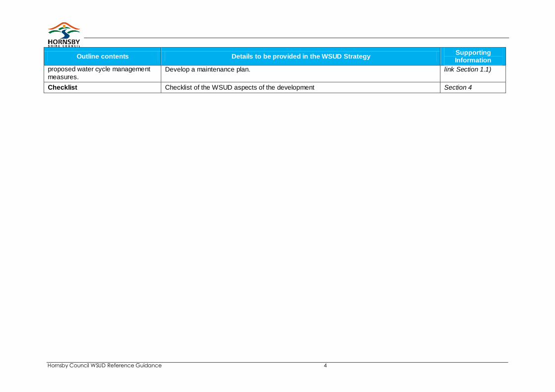
Hornsby Council WSUD Reference Guidance 4
Outline contents Details to be provided in the WSUD Strategy Supporting Information
proposed water cycle management
measures. Develop a maintenance plan. link Section 1.1)
Checklist Checklist of the WSUD aspects of the development Section 4
Hornsby Council WSUD Reference Guidance 5
2.5 Supporting Information for the preparation of a WSUD Strategy
When preparing a Development Application a proponent is required to employ the services of appropriately qualified and experienced practitioners for the development of an appropriate WSUD strategy for their site. The following information should be referred to when developing that strategy.
1. MUSIC Model – MUSIC, the Model for Urban Stormwater Improvement Conceptualisation, derives default water quality parameters for a range of pollutants generated from various land use types. As presented in Australian Runoff Quality (Engineers Australia)
1 most verified and published
Australian water quality research has been synthesised and incorporated into MUSIC. The latest version of MUSIC is Version 5 (2011), and is available for purchase at eWater. The MUSIC model includes a modelling guideline which should be referred to when using the MUSIC software. Parameters for the MUSIC model in Hornsby are outlined in this document.
2. MUSIC Modelling guide – the development of a MUSIC model requires specific inputs and parameters. For proposed developments in the Hornsby Council LGA key parameters for undertaking any MUSIC modelling are outlined in Section 2 of this document. Further information on MUSIC modelling is available in the Draft NSW MUSIC Modelling Guideline. See http://www.wsud.org/resources-examples/tools-resources/
3. WSUD Conceptual Design Information – information on specific WSUD elements (such as rainwater tanks, bioretention and wetlands) and where they are appropriate is available in the South East Queensland’s (SEQ) ‘Water by Design’ Program’s Concept Design Guidelines for WSUD. This document provides an industry standard and seeks to assist multi-disciplinary teams conceptualise and develop design solutions that integrate best practice sustainable urban water management within the urban form. The Sydney Metropolitan Catchment Management A Sydney based guide has been produced that replaces Queensland references with Sydney specific alternatives available. See http://www.wsud.org/resources-examples/tools-resources/
2.6 Further Information beyond the Development Application stage
The following resources outline further information which can be used by proponents when developing detailed design / construction drawings and undertaking construction.
1 Engineers Australia (2006), Australian Runoff Quality, Melbourne, Australia.
Hornsby Council WSUD Reference Guidance 6
4. Technical Design Manual – the ‘Water by Design’ Program’s WSUD Technical Design Guidelines for South East Queensland describe appropriate methods for the detailed design of some common structural stormwater management measures.
5. Typical Drawings – the Sydney Metropolitan CMA has released typical drawings for a series of WSUD elements, including bioretention systems at steep or flat sites, in footpaths or roadways. See http://www.wsud.org/resources-examples/tools-resources/
6. Construction and Establishment for Swales, Bioretention Systems and Wetlands – the South East Queensland ‘Water by Design’ Program has produced Construction and Establishment Guidelines, providing guidance on common construction and establishment issues associated with the delivery of vegetated WSUD elements, assisting practitioners to avoid common faults and potential failure at the delivery and design stage. A Sydney based guide has been produced that replaces Queensland references with Sydney specific alternatives available. See http://www.wsud.org/resources-examples/tools-resources/
2.7 Engaging a Consultant to develop a WSUD Strategy
Applicants and developers are required to employ the services of appropriately qualified and experienced practitioners for the development of the WSUD Strategy. Consultants with skills in WSUD include those with:
Advanced MUSIC modelling training and experience
Demonstrated experience in designing WSUD elements
The benefit of using consultants with demonstrated capacity to undertake a WSUD Strategy will generally reflect a smoother and straight forward approval process.
Members of the NSW Stormwater Industry Association can provide a first starting point.
Hornsby Council WSUD Reference Guidance 7
3. MUSIC Modelling Parameters for Hornsby
This section provides guidance on modelling parameters to be used when modelling WSUD elements in MUSIC. These guidelines are provided to ensure consultants, developers and Council have a consistent and uniform approach to stormwater quality and harvesting modelling within the Hornsby local government area. The parameters outlined in this section should be used at all times when developing a WSUD Strategy to meet the targets outlined in Hornsby Council’s DCP. Further information on MUSIC Modelling is available in the Draft NSW MUSIC Modelling Guideline (see http://www.wsud.org/resources-examples/tools-resources/). The information contained herein is an adaption of the Draft NSW MUSIC Modelling Guideline and should be read in conjunction with the eWater MUSIC User Guide which is provided with the MUSIC software (2011). This guideline provides specific guidance on rainfall and evaporation inputs, source node parameters, rainfall runoff parameters, pollutant generation parameters and stormwater treatment nodes. Any MUSIC models that are not consistent with this guideline must justify the differences in parameters and/or assessment methods.
3.1 Rainfall & evaporation inputs
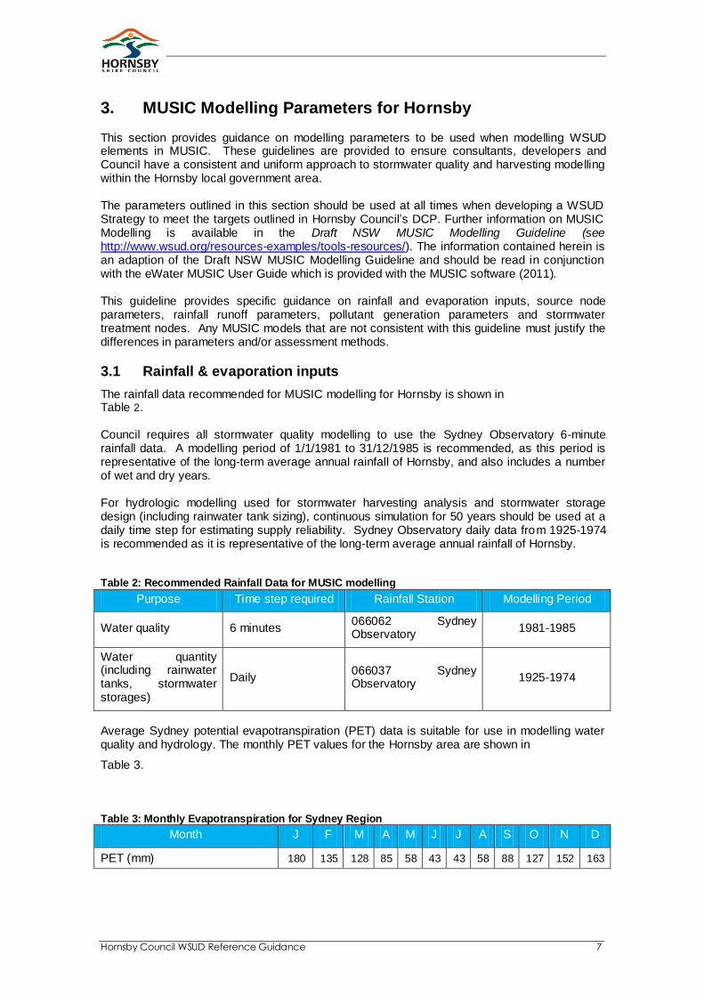
The rainfall data recommended for MUSIC modelling for Hornsby is shown in Table 2. Council requires all stormwater quality modelling to use the Sydney Observatory 6-minute rainfall data. A modelling period of 1/1/1981 to 31/12/1985 is recommended, as this period is representative of the long-term average annual rainfall of Hornsby, and also includes a number of wet and dry years. For hydrologic modelling used for stormwater harvesting analysis and stormwater storage design (including rainwater tank sizing), continuous simulation for 50 years should be used at a daily time step for estimating supply reliability. Sydney Observatory daily data from 1925-1974 is recommended as it is representative of the long-term average annual rainfall of Hornsby. Table 2: Recommended Rainfall Data for MUSIC modelling
Purpose Time step required Rainfall Station Modelling Period
Water quality 6 minutes 066062 Sydney Observatory
1981-1985
Water quantity (including rainwater tanks, stormwater storages)
Daily 066037 Sydney Observatory
1925-1974
Average Sydney potential evapotranspiration (PET) data is suitable for use in modelling water quality and hydrology. The monthly PET values for the Hornsby area are shown in
Table 3.
Table 3: Monthly Evapotranspiration for Sydney Region
Month J F M A M J J A S O N D
PET (mm) 180 135 128 85 58 43 43 58 88 127 152 163

Hornsby Council WSUD Reference Guidance 8
3.2 Source node inputs
3.2.1 Rainfall runoff parameters
MUSIC rainfall-runoff parameters have been derived for NSW from model calibration studies.
Hornsby Council WSUD Reference Guidance 9
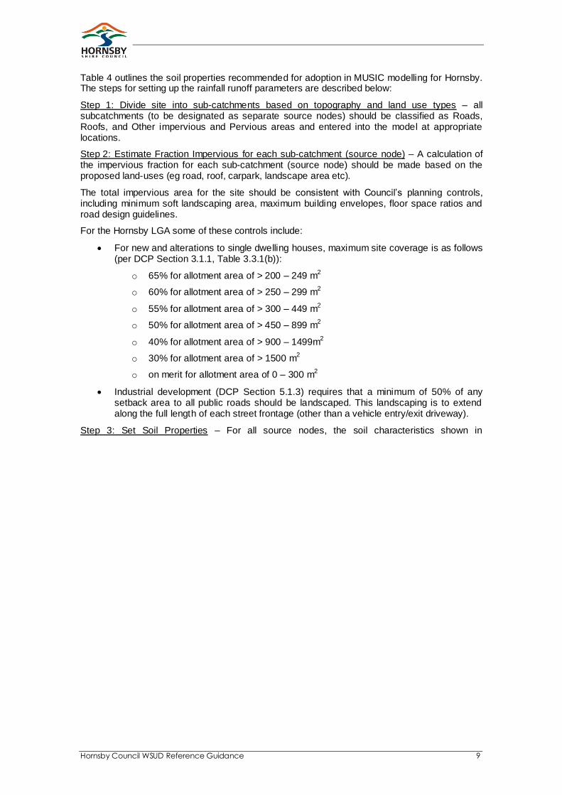
Table 4 outlines the soil properties recommended for adoption in MUSIC modelling for Hornsby. The steps for setting up the rainfall runoff parameters are described below:
Step 1: Divide site into sub-catchments based on topography and land use types – all subcatchments (to be designated as separate source nodes) should be classified as Roads, Roofs, and Other impervious and Pervious areas and entered into the model at appropriate locations.
Step 2: Estimate Fraction Impervious for each sub-catchment (source node) – A calculation of the impervious fraction for each sub-catchment (source node) should be made based on the proposed land-uses (eg road, roof, carpark, landscape area etc).
The total impervious area for the site should be consistent with Council’s planning controls, including minimum soft landscaping area, maximum building envelopes, floor space ratios and road design guidelines.
For the Hornsby LGA some of these controls include:
For new and alterations to single dwelling houses, maximum site coverage is as follows (per DCP Section 3.1.1, Table 3.3.1(b)):
o 65% for allotment area of > 200 – 249 m2
o 60% for allotment area of > 250 – 299 m2
o 55% for allotment area of > 300 – 449 m2
o 50% for allotment area of > 450 – 899 m2
o 40% for allotment area of > 900 – 1499m2
o 30% for allotment area of > 1500 m2
o on merit for allotment area of 0 – 300 m2
Industrial development (DCP Section 5.1.3) requires that a minimum of 50% of any setback area to all public roads should be landscaped. This landscaping is to extend along the full length of each street frontage (other than a vehicle entry/exit driveway).
Step 3: Set Soil Properties – For all source nodes, the soil characteristics shown in

Hornsby Council WSUD Reference Guidance 10
Table 4 should be adopted in MUSIC. These parameters have been derived based on typical soils found in the Hornsby LGA. Use of different soil parameters must be justified.
3.2.2 Pollutant generation parameters
The development of the MUSIC software included a comprehensive review of stormwater quality in urban catchments, which forms the basis for the default values of event mean concentrations for total suspended solids (TSS), total phosphorous (TP) and total nitrogen (TN).
Table 5 presents the recommended stormwater quality parameters for various land use categories in MUSIC. Note that for all simulations the MUSIC model must be run with pollutant export estimation method set to “stochastically generated” as opposed to the “mean” estimation method.
Hornsby Council WSUD Reference Guidance 11
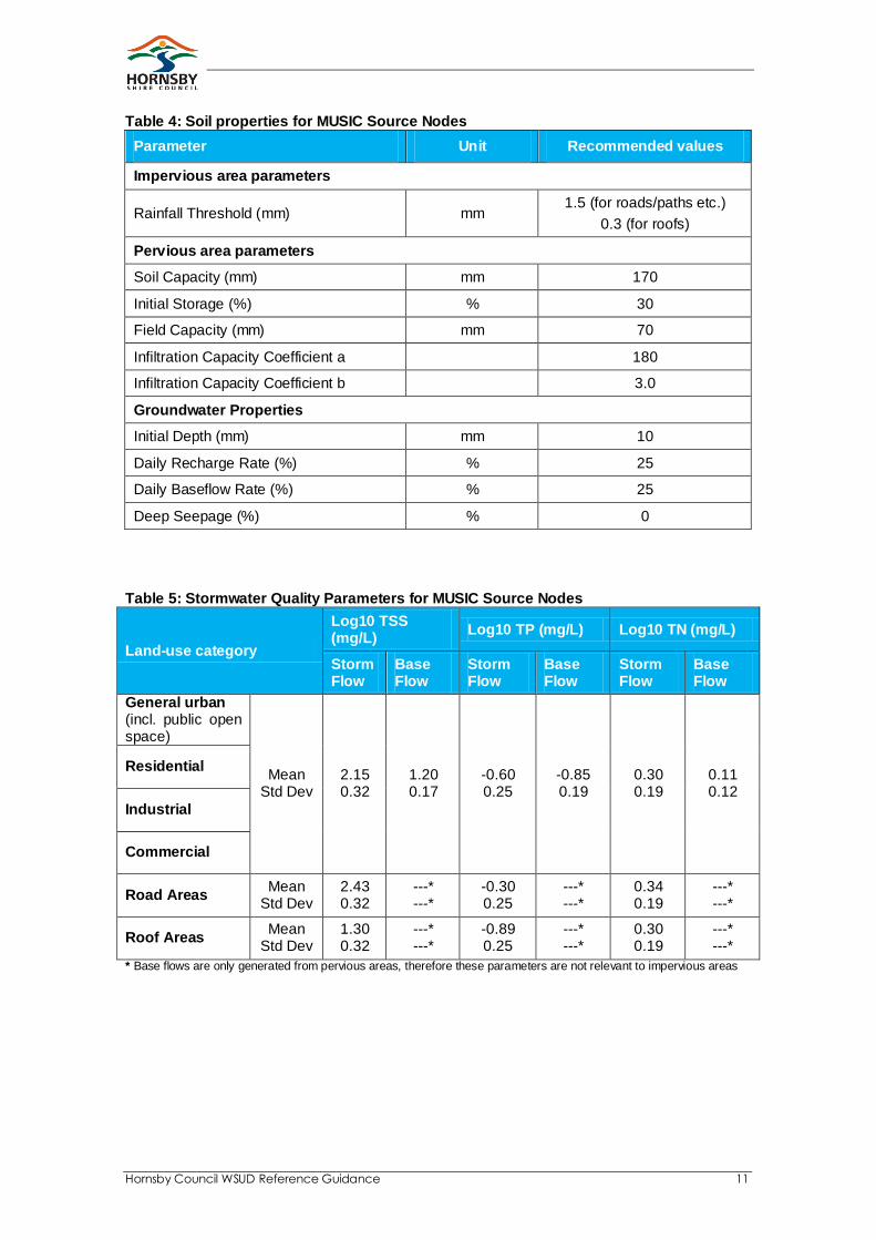
Table 4: Soil properties for MUSIC Source Nodes
Parameter Unit Recommended values
Impervious area parameters
Rainfall Threshold (mm) mm 1.5 (for roads/paths etc.)
0.3 (for roofs)
Pervious area parameters
Soil Capacity (mm) mm 170
Initial Storage (%) % 30
Field Capacity (mm) mm 70
Infiltration Capacity Coefficient a 180
Infiltration Capacity Coefficient b 3.0
Groundwater Properties
Initial Depth (mm) mm 10
Daily Recharge Rate (%) % 25
Daily Baseflow Rate (%) % 25
Deep Seepage (%) % 0
Table 5: Stormwater Quality Parameters for MUSIC Source Nodes
Land-use category
Log10 TSS (mg/L)
Log10 TP (mg/L) Log10 TN (mg/L)
Storm Flow
Base Flow
Storm Flow
Base Flow
Storm Flow
Base Flow
General urban (incl. public open space)
Mean Std Dev
2.15 0.32
1.20 0.17
-0.60 0.25
-0.85 0.19
0.30 0.19
0.11 0.12
Residential
Industrial
Commercial
Road Areas Mean
Std Dev 2.43 0.32
---* ---*
-0.30 0.25
---* ---*
0.34 0.19
---* ---*
Roof Areas Mean
Std Dev 1.30 0.32
---* ---*
-0.89 0.25
---* ---*
0.30 0.19
---* ---*
* Base flows are only generated from pervious areas, therefore these parameters are not relevant to impervious areas
Hornsby Council WSUD Reference Guidance 12
3.3 Treatment node inputs
To meet the site’s stormwater quality objectives the development will need to incorporate an appropriate stormwater treatment process for the development, dependent on site constraints and opportunities.
The default parameters in MUSIC for the first order decay k-C* model used to define the treatment efficiency of each treatment device should be used unless local relevant treatment performance monitoring can be used as reasonable justification for modification of the default parameters. Reference should be made to the MUSIC User Manual.
Note: The following devices are not to be modelled within the MUSIC program: Natural waterways, Natural wetlands, Naturalised channel systems, Environmental buffers and ornamental Lake/Pond systems.
In order to avoid any confusion relating to treatment node implementation Council provides the following advice for modelling stormwater quality treatment systems within the Hornsby LGA.
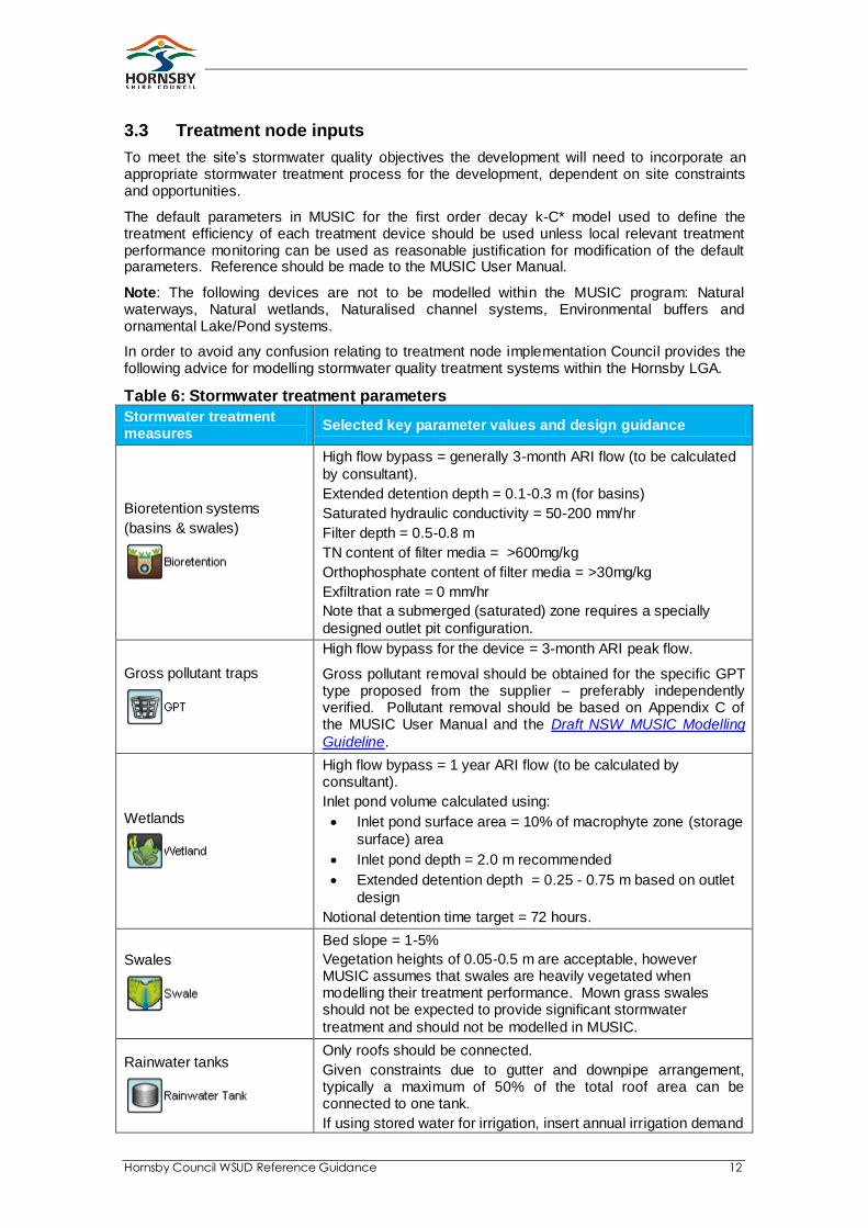
Table 6: Stormwater treatment parameters
Stormwater treatment measures
Selected key parameter values and design guidance
Bioretention systems
(basins & swales)
High flow bypass = generally 3-month ARI flow (to be calculated
by consultant).
Extended detention depth = 0.1-0.3 m (for basins)
Saturated hydraulic conductivity = 50-200 mm/hr
Filter depth = 0.5-0.8 m
TN content of filter media = >600mg/kg
Orthophosphate content of filter media = >30mg/kg
Exfiltration rate = 0 mm/hr
Note that a submerged (saturated) zone requires a specially
designed outlet pit configuration.
Gross pollutant traps
High flow bypass for the device = 3-month ARI peak flow.
Gross pollutant removal should be obtained for the specific GPT type proposed from the supplier – preferably independently verified. Pollutant removal should be based on Appendix C of the MUSIC User Manual and the Draft NSW MUSIC Modelling
Guideline.
Wetlands
High flow bypass = 1 year ARI flow (to be calculated by consultant).
Inlet pond volume calculated using:
Inlet pond surface area = 10% of macrophyte zone (storage
surface) area
Inlet pond depth = 2.0 m recommended
Extended detention depth = 0.25 - 0.75 m based on outlet
design
Notional detention time target = 72 hours.
Swales
Bed slope = 1-5%
Vegetation heights of 0.05-0.5 m are acceptable, however MUSIC assumes that swales are heavily vegetated when modelling their treatment performance. Mown grass swales should not be expected to provide significant stormwater
treatment and should not be modelled in MUSIC.
Rainwater tanks
Only roofs should be connected.
Given constraints due to gutter and downpipe arrangement, typically a maximum of 50% of the total roof area can be connected to one tank.
If using stored water for irrigation, insert annual irrigation demand

Hornsby Council WSUD Reference Guidance 13
Stormwater treatment measures
Selected key parameter values and design guidance
(kL/yr) and provide other irrigation estimation details. For a daily demand (kL/day), make estimation based on proposed building design with calculations of proposed demands to be connected
(e.g. toilet flushing and/or washing machines).
Infiltration systems
Infiltration is not a stormwater treatment measure and stormwater treatment should be provided upstream of infiltration basins.
MUSIC pollutant removal parameters assume that the basin is vegetated and that stormwater is pre-treated to remove coarse sediment upstream of the retention/infiltration basin. If these assumptions are not true, then the basin should not be expected
to meet the pollutant removal performance estimated in MUSIC.
Water quality ponds
(note there are separate procedures for modelling
water storage ponds)
Permanent pool = 1.0-2.0 m
Extended detention depth = 0.25-1.0 m.
Parameters within the MUSIC model assume that stormwater is pre-treated to remove coarse sediment upstream of the pond, therefore ponds should never be designed without pre-treatment
(such as a swale or sedimentation basin).
Sedimentation basins
Permanent pool volume based on 2 m depth (e.g. with a surface area of 50m
2 the PPV would be 100m
3)
Extended detention depth = 0.25-1.0 m
Detention basins
Refer to Council’s ‘Stormwater and On Site Detention Code (1999)’ for details on OSD requirements.
Buffers
Buffer strips are only applicable where runoff is distributed across
the whole buffer strip and the buffer strip slope is 5%
Media filtration systems
(e.g. sand filters)
As per bioretention systems (without vegetation)
Generic
For modelling a treatment device that is not a specific node within the program. This option should only be used is the user has sufficient data to model it effectively. Examples of applications
include flow diversions, or sewer overflows.
ALL TREATMENT NODES
If infiltration is allowable based on a site specific investigation, seepage loss (exfiltration rate) should be as follows:
- 36 mm/hr for sandy sites (within soil landscape zone tu)
- 3.6 mm/hr for sandy clay loam (within soil landscape zones
gy, ha, dc)
If site specific hydraulic conductivity tests are carried out these
can be used to set an alternative exfiltration rate.
Evaporative loss should normally range from 75% of PET for completely open water to 125% of PET for heavily vegetated
water bodies.
ALL “ADVANCED PROPERTIES”
(k-C* values, orifice discharge and weir
As per MUSIC default values

Hornsby Council WSUD Reference Guidance 14
Stormwater treatment measures
Selected key parameter values and design guidance
coefficients, void ratio,
number of CSTR cells)
Hornsby Council WSUD Reference Guidance 15
4. Bioretention Systems as WSUD Treatment
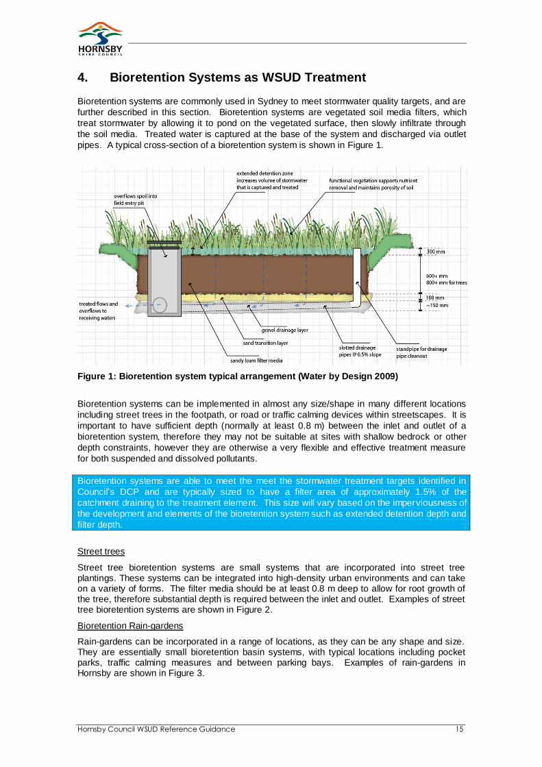
Bioretention systems are commonly used in Sydney to meet stormwater quality targets, and are
further described in this section. Bioretention systems are vegetated soil media filters, which
treat stormwater by allowing it to pond on the vegetated surface, then slowly infiltrate through
the soil media. Treated water is captured at the base of the system and discharged via outlet
pipes. A typical cross-section of a bioretention system is shown in Figure 1.
Figure 1: Bioretention system typical arrangement (Water by Design 2009)
Bioretention systems can be implemented in almost any size/shape in many different locations
including street trees in the footpath, or road or traffic calming devices within streetscapes. It is
important to have sufficient depth (normally at least 0.8 m) between the inlet and outlet of a
bioretention system, therefore they may not be suitable at sites with shallow bedrock or other
depth constraints, however they are otherwise a very flexible and effective treatment measure
for both suspended and dissolved pollutants.
Bioretention systems are able to meet the meet the stormwater treatment targets identified in
Council’s DCP and are typically sized to have a filter area of approximately 1.5% of the
catchment draining to the treatment element. This size will vary based on the imperviousness of
the development and elements of the bioretention system such as extended detention depth and
filter depth.
Street trees
Street tree bioretention systems are small systems that are incorporated into street tree plantings. These systems can be integrated into high-density urban environments and can take on a variety of forms. The filter media should be at least 0.8 m deep to allow for root growth of the tree, therefore substantial depth is required between the inlet and outlet. Examples of street tree bioretention systems are shown in Figure 2.
Bioretention Rain-gardens
Rain-gardens can be incorporated in a range of locations, as they can be any shape and size. They are essentially small bioretention basin systems, with typical locations including pocket parks, traffic calming measures and between parking bays. Examples of rain-gardens in Hornsby are shown in Figure 3.
Hornsby Council WSUD Reference Guidance 16
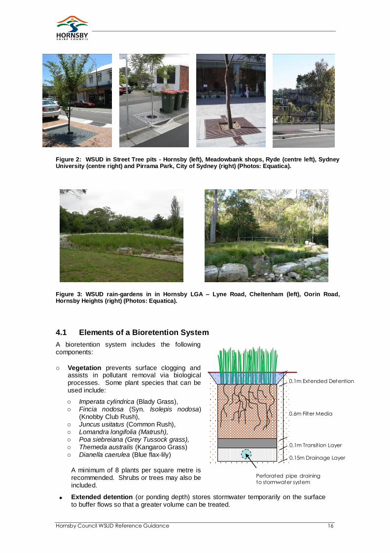
Figure 2: WSUD in Street Tree pits - Hornsby (left), Meadowbank shops, Ryde (centre left), Sydney University (centre right) and Pirrama Park, City of Sydney (right) (Photos: Equatica).
Figure 3: WSUD rain-gardens in in Hornsby LGA – Lyne Road, Cheltenham (left), Oorin Road, Hornsby Heights (right) (Photos: Equatica).
4.1 Elements of a Bioretention System
A bioretention system includes the following components:
o Vegetation prevents surface clogging and assists in pollutant removal via biological processes. Some plant species that can be used include:
o Imperata cylindrica (Blady Grass), o Fincia nodosa (Syn. Isolepis nodosa)
(Knobby Club Rush), o Juncus usitatus (Common Rush), o Lomandra longifolia (Matrush), o Poa siebreiana (Grey Tussock grass), o Themeda australis (Kangaroo Grass) o Dianella caerulea (Blue flax-lily)
A minimum of 8 plants per square metre is recommended. Shrubs or trees may also be included.
Extended detention (or ponding depth) stores stormwater temporarily on the surface to buffer flows so that a greater volume can be treated.
0.1m Extended Detention
0.6m Filter Media
0.15m Drainage Layer
0.1m Transition Layer
Perforated pipe draining to stormwater system

Hornsby Council WSUD Reference Guidance 17
The filter media is the principal treatment zone. As stormwater passes through the filter media, pollutants are removed by filtration, adsorption and biological processes. The filter media should normally be 0.6 m deep, and 0.3 m is the minimum acceptable depth where the site is constrained. The filter media should be a loamy sand with a permeability of 100-300 mm/hr under compaction and should be clean and free of weeds. The filter media should contain some organic matter (less than 5%) but be low in nutrient content. No fertiliser is to be added.
A transition layer of clean well graded sand/coarse sand prevents the filter media from washing out of the system
The drainage layer of clean fine gravel (2-5 mm) collects treated water at the base of the system and contains 90-100 mm perforated pipes to convey treated water out of the system
An impervious liner may be required to prevent infiltration into surrounding soils, particularly if the treatment system is immediately adjacent to roads or buildings where infiltration may cause structural issues. Note that geotextile filters should not be used within the bioretention system, as they are prone to clogging. If perforated pipes come with a geotextile sock, this should be discarded before installation.
An inlet for stormwater runoff. The inlet should be designed to protect the surface of the bioretention system from scour and erosion
An overflow pit (or other controlled overflow point) to allow high flows, beyond the capacity of the treatment system, to escape to the stormwater drainage system in a controlled manner
A flushing point connected to the perforated pipes, so they can be cleaned in the event of blockage
Edge treatment (e.g. a raised kerb or series of bollards) may be required to protect the bioretention system from traffic
Pre-treatment is recommended when sediment loads are likely to be high, or if there is a risk of spills. The simplest option is to incorporate a pit with a sump immediately upstream of the bioretention system.
4.2 Detailed design guidance
Design guidance in the form of typical drawings for bioretention systems at steep or flat sites, in footpaths or roadways, has been developed by the WSUD in Sydney program and is available at the following link - http://www.wsud.org/resources-examples/tools-resources/.
4.3 Construction and Maintenance
During the construction phase, bioretention systems should be protected from high sediment loads associated with construction on site (erosion and sediment control measures should be in place to manage stormwater during this phase). The bioretention system should be connected at the end of the construction phase.
Regular maintenance is important to ensure the ongoing performance of bioretention systems. Maintenance requirements of bioretention systems include:
Monitoring for scour and erosion, and sediment or litter build-up
Weed removal and plant re-establishment
Monitoring overflow pits for structural integrity and blockage
Inlet and
scour
protection
Overflow pit
Flushing point for perforated pipes
Filter area, typically 1.5%
of total
development
site area
Hornsby Council WSUD Reference Guidance 18
Further information is available in the Construction and Establishment for Swales, Bioretention Systems and Wetlands guidelines, as outlined in Section 1.
4.4 Requirement for a Management Plan for Issue of a Construction Certificate
As part of the conditions required for the issuing of a Construction Certificate, a proponent is required to prepare a detailed stormwater quality treatment Design and associated Management Plan prepared by a suitably qualified practicing professional. Each physical component of the treatment train identified in the WSUD Strategy must be included in the detailed design. The Design must be prepared to make provision for the following:
The stormwater quality treatment Design and Management Plan must be generally in accordance with the Water Sensitive Urban Design (WSUD) Strategy in Report titled [REPORT TITLE] and Drawing No [DRAWING No] prepared by [CONSULTANT NAME] and dated [DATE] and [DATE] respectively.
The Design must address stormwater pollutant loads generated within the property. The applicable water quality targets provided in Section 2.17, Water Sensitive Urban Design, of Council’s DCP [year] must be shown on the Plan together with each physical component of the stormwater treatment train.
The Management Plan must outline how all elements of the water quality treatment facility will be maintained and renewed, including estimates of capital, operation, and maintenance costs. The Management Plan must provide a summary timeline of maintenance actions together with a pictorial/diagrammatic rendering of the water quality treatment facility.

Hornsby Council WSUD Reference Guidance 19
5. Applicant Lodgement Checklist for WSUD Strategy
This lodgement checklist is to be used by Applicants who are required to complete a WSUD
Strategy to meet the requirements of Hornsby Council’s WSUD DCP.
Detail
Location of Information
(eg p2 of WSUD Report,
drawing3a.dwg)
Information
Supplied
Yes / No
Proposed development – Information on the development site, including existing site conditions, site boundaries, proposed land uses, densities, population, infrastructure, development staging.
WSUD objectives
Stormwater quality - demonstrate how the stormwater quality targets will be met. The WSUD Strategy should include stormwater quality modelling results and identify the location, size and configuration of stormwater treatment measures
proposed for the development.
Costs - capital and operation and maintenance cost estimates of proposed WSUD measures.
Maintenance Plan – A maintenance plan should outline how the WSUD elements will be maintained.
Appendix A – MUSIC Model, including:
• Sqn or Sqz model of catchment with treatment measures. (to be supplied electronically, by email or CD)
• Sqn or Sqz model of catchment without treatment measures. (to be supplied electronically, by email or CD)
• Electronic / hard copy of the catchment and subcatchment from MapInfo or other approved format.
Modelling Assumptions and inputs, including:
• Description of rainfall/ET data used
• Catchment details and a description of the approach taken.
• Description of how fraction impervious was calculated (what figures were used for different zonings).
• Description of and documentation for any departure from the “MUSIC Inputs” outlined in Section 2.5.
Modelling Results, including:
• Mean annual load reduction for TSS, TP and TN
• % reduction of each treatment system
• % reduction of total treatment system
• Description of the function and intent of the treatment system.
Hornsby Council WSUD Reference Guidance 20
6. Case Study – Industrial
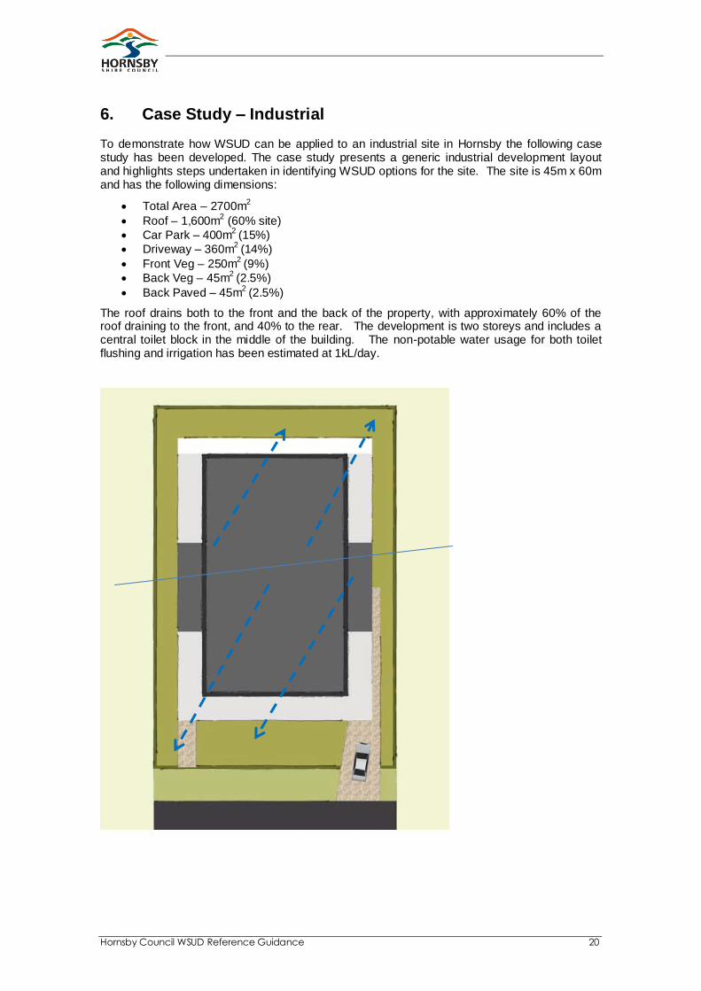
To demonstrate how WSUD can be applied to an industrial site in Hornsby the following case study has been developed. The case study presents a generic industrial development layout and highlights steps undertaken in identifying WSUD options for the site. The site is 45m x 60m and has the following dimensions:
Total Area – 2700m2
Roof – 1,600m2 (60% site)
Car Park – 400m2
(15%)
Driveway – 360m2
(14%)
Front Veg – 250m2
(9%)
Back Veg – 45m2
(2.5%)
Back Paved – 45m2
(2.5%)
The roof drains both to the front and the back of the property, with approximately 60% of the roof draining to the front, and 40% to the rear. The development is two storeys and includes a central toilet block in the middle of the building. The non-potable water usage for both toilet flushing and irrigation has been estimated at 1kL/day.
Hornsby Council WSUD Reference Guidance 21
6.1 Sizing Stormwater Treatment Systems
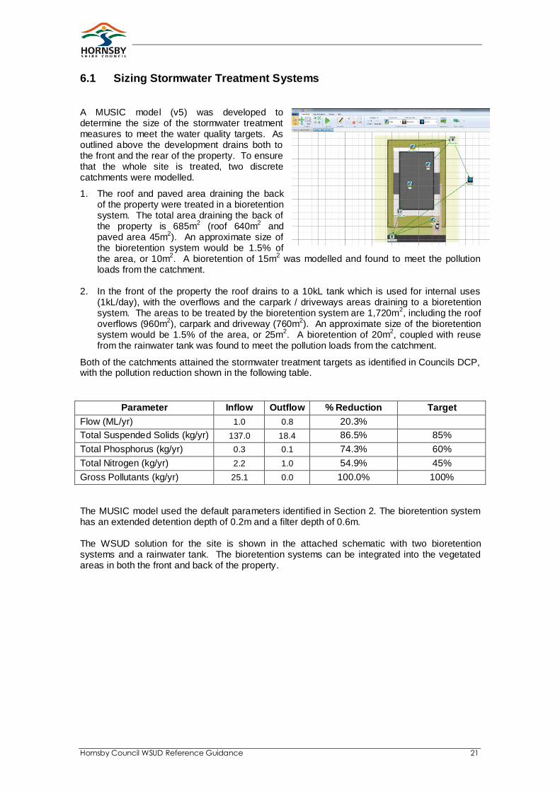
A MUSIC model (v5) was developed to determine the size of the stormwater treatment measures to meet the water quality targets. As outlined above the development drains both to the front and the rear of the property. To ensure that the whole site is treated, two discrete catchments were modelled.
1. The roof and paved area draining the back of the property were treated in a bioretention system. The total area draining the back of the property is 685m
2 (roof 640m
2 and
paved area 45m2). An approximate size of
the bioretention system would be 1.5% of the area, or 10m
2. A bioretention of 15m
2 was modelled and found to meet the pollution
loads from the catchment.
2. In the front of the property the roof drains to a 10kL tank which is used for internal uses (1kL/day), with the overflows and the carpark / driveways areas draining to a bioretention system. The areas to be treated by the bioretention system are 1,720m
2, including the roof
overflows (960m2), carpark and driveway (760m
2). An approximate size of the bioretention
system would be 1.5% of the area, or 25m2. A bioretention of 20m
2, coupled with reuse
from the rainwater tank was found to meet the pollution loads from the catchment.
Both of the catchments attained the stormwater treatment targets as identified in Councils DCP, with the pollution reduction shown in the following table.
Parameter Inflow Outflow % Reduction Target
Flow (ML/yr) 1.0 0.8 20.3%
Total Suspended Solids (kg/yr) 137.0 18.4 86.5% 85%
Total Phosphorus (kg/yr) 0.3 0.1 74.3% 60%
Total Nitrogen (kg/yr) 2.2 1.0 54.9% 45%
Gross Pollutants (kg/yr) 25.1 0.0 100.0% 100%
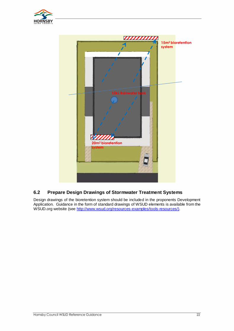
The MUSIC model used the default parameters identified in Section 2. The bioretention system has an extended detention depth of 0.2m and a filter depth of 0.6m. The WSUD solution for the site is shown in the attached schematic with two bioretention systems and a rainwater tank. The bioretention systems can be integrated into the vegetated areas in both the front and back of the property.
Hornsby Council WSUD Reference Guidance 22
6.2 Prepare Design Drawings of Stormwater Treatment Systems
Design drawings of the bioretention system should be included in the proponents Development Application. Guidance in the form of standard drawings of WSUD elements is available from the WSUD.org website (see http://www.wsud.org/resources-examples/tools-resources/).
15m2 bioretention system
10kL Rainwater tank
20m2 bioretention
system
Hornsby Council WSUD Reference Guidance 23
7. Case Study – High Density Residential
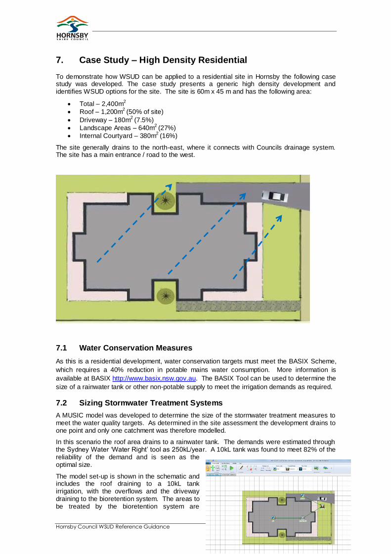
To demonstrate how WSUD can be applied to a residential site in Hornsby the following case study was developed. The case study presents a generic high density development and identifies WSUD options for the site. The site is 60m x 45 m and has the following area:
Total – 2,400m2
Roof – 1,200m2
(50% of site)
Driveway – 180m2
(7.5%)
Landscape Areas – 640m2
(27%)
Internal Courtyard – 380m2
(16%)
The site generally drains to the north-east, where it connects with Councils drainage system. The site has a main entrance / road to the west.
7.1 Water Conservation Measures
As this is a residential development, water conservation targets must meet the BASIX Scheme,
which requires a 40% reduction in potable mains water consumption. More information is
available at BASIX http://www.basix.nsw.gov.au. The BASIX Tool can be used to determine the
size of a rainwater tank or other non-potable supply to meet the irrigation demands as required.
7.2 Sizing Stormwater Treatment Systems
A MUSIC model was developed to determine the size of the stormwater treatment measures to meet the water quality targets. As determined in the site assessment the development drains to one point and only one catchment was therefore modelled.
In this scenario the roof area drains to a rainwater tank. The demands were estimated through the Sydney Water ‘Water Right’ tool as 250kL/year. A 10kL tank was found to meet 82% of the reliability of the demand and is seen as the optimal size.
The model set-up is shown in the schematic and includes the roof draining to a 10kL tank irrigation, with the overflows and the driveway draining to the bioretention system. The areas to be treated by the bioretention system are
Hornsby Council WSUD Reference Guidance 24
1,835m2, including the roof overflows (1,700
2) and driveway (135m
2). An approximate size of
the bioretention system would be 1.5% of the area, or approximately 30m2. A bioretention of
25m2, coupled with reuse from the rainwater tank was found to meet the pollution loads from the
catchment. The bioretention system has an extended detention depth of 0.2m and a filter depth of 0.6m. The MUSIC modelling results are shown in the following table.
Parameter Inflow Outflow % Reduction Target
Flow (ML/yr) 1.3 1.0 20.0%
Total Suspended Solids (kg/yr) 87.6 10.0 88.6% 85%
Total Phosphorus (kg/yr) 0.3 0.1 53.6% 60%
Total Nitrogen (kg/yr) 2.8 1.1 62.0% 45%
Gross Pollutants (kg/yr) 32.4 0.0 100.0% 100%
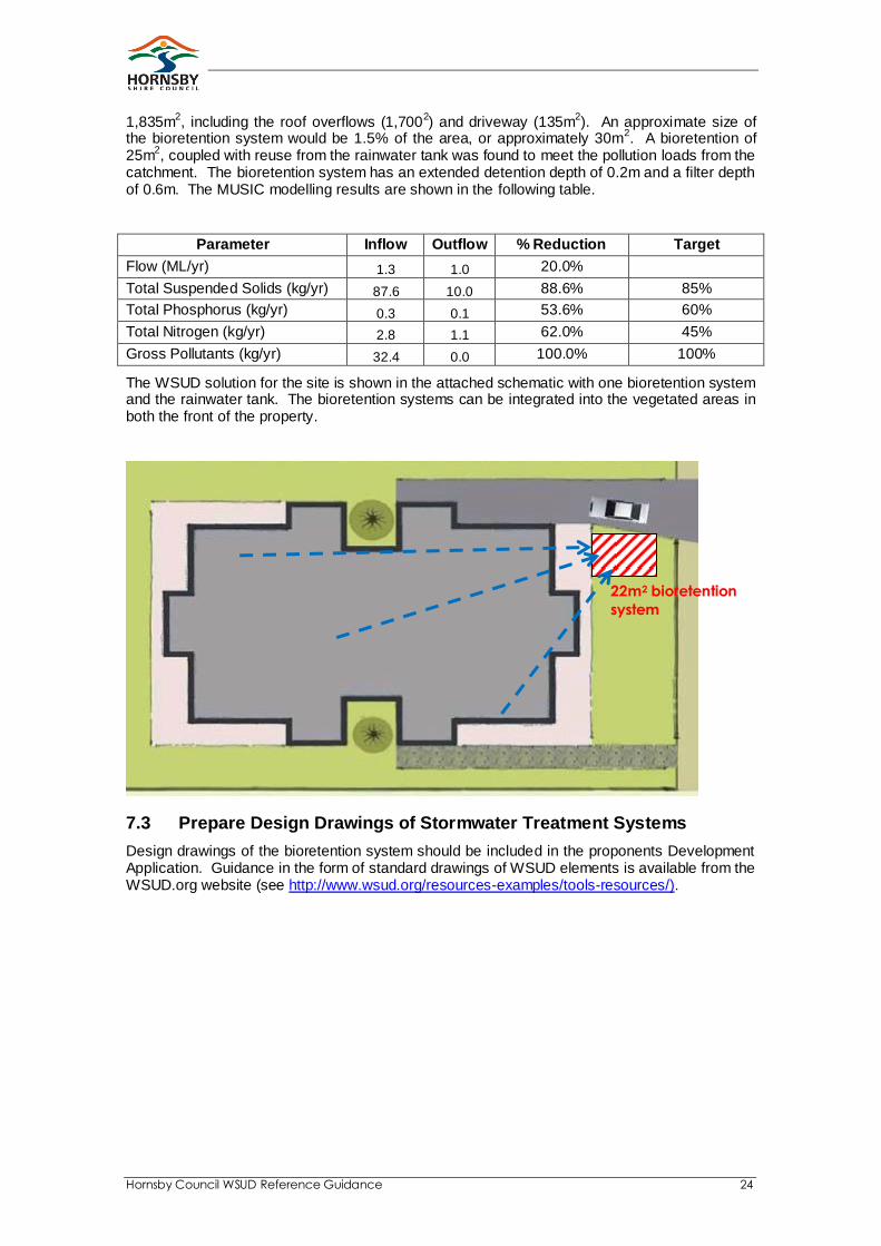
The WSUD solution for the site is shown in the attached schematic with one bioretention system and the rainwater tank. The bioretention systems can be integrated into the vegetated areas in both the front of the property.
7.3 Prepare Design Drawings of Stormwater Treatment Systems
Design drawings of the bioretention system should be included in the proponents Development Application. Guidance in the form of standard drawings of WSUD elements is available from the WSUD.org website (see http://www.wsud.org/resources-examples/tools-resources/).
22m2 bioretention
system
Hornsby Council WSUD Reference Guidance 25
8. References
Full web addresses are provided for the weblinks throughout this document: WSUD.org Typical WSUD Drawings http://www.wsud.org/resources-examples/tools-resources/ Sydney CMA Draft NSW MUSIC Modelling Guideline http://www.wsud.org/resources-examples/tools-resources/ eWater – MUSIC software http://www.ewater.com.au/products/ewater-toolkit/urban-tools/music/ South East Queensland’s (SEQ) ‘Water by Design’ Program’s WSUD Technical Design Guidelines for South East Queensland. http://waterbydesign.com.au/TechGuide/ South East Queensland’s (SEQ) ‘Water by Design’ Program’s Concept Design Guidelines for WSUD. http://waterbydesign.com.au/conceptguide/ Sydney Metropolitan CMA Concept Design Interim Reference Guideline. http://www.wsud.org/resources-examples/tools-resources/ South East Queensland ‘Water by Design’ Program Construction and Establishment Guidelines, http://waterbydesign.com.au/CEguide/ Sydney Metropolitan CMA Construction and Establishment Interim Reference Guideline. http://www.wsud.org/resources-examples/tools-resources/
Hornsby Council WSUD Reference Guidance 26
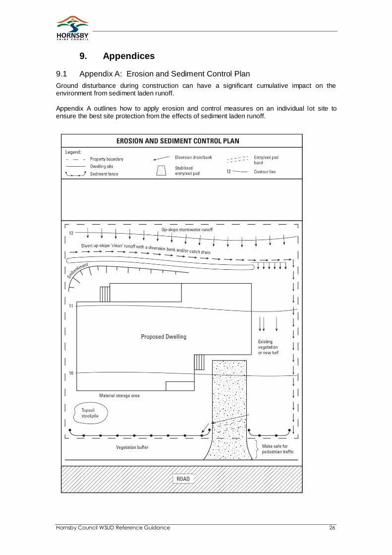
9. Appendices
9.1 Appendix A: Erosion and Sediment Control Plan
Ground disturbance during construction can have a significant cumulative impact on the environment from sediment laden runoff. Appendix A outlines how to apply erosion and control measures on an individual lot site to ensure the best site protection from the effects of sediment laden runoff.