Embed Size (px)
Citation preview
Rev. 12/16/2015 WTJ-HITCH, MANUAL
Copyright 2015 Vestil Manufacturing Co. Page 1 of 9
WTJ-HITCH Series Hitch-Mounted Jib Cranes Use and Maintenance Manual
Receiving instructions:
After delivery, IMMEDIATELY remove the packaging from the product in a manner that preserves the packaging and maintains the orientation of the product in the packaging; then inspect the product closely to determine whether it sustained damage during transport. If damage is discovered during the inspection, immediately record a complete description of the damage on the bill of lading. If the product is undamaged, discard the packaging. NOTES: 1) Compliance with laws, regulations, codes, and non-voluntary standards enforced in the location where the product is used is exclusively the responsibility of the owner/end-user 2) VESTIL is not liable for any injury or property damage that occurs as a consequence of failing to apply either: a) Instructions in this manual; or b) information provided on labels affixed to the product. Vestil is also not responsible for any consequential damages sustained as a result of assembling, installing, using or maintaining this product.
Table of Contents Product Specifications……………….…………………..…………………………………………………………………….. 2 Signal Words….……………………..………………………………………………………………………………………….. 2 Safe Use Recommendations……………………………………………………………..…………………………………… 3 Labeling Diagram……...……………………………………………………………………………………………………….. 3 FIG. 1: WTJ-HITCH exploded parts diagram & bill of materials……………………………………………………………4 Assembly instructions………………………………………………………………………………………………………….. 5-7 Post angle adjustments……………….………………………………………………………………………………............. 7 Operation instructions………………………………………………………………………………………………………….. 7-8 Inspections & Maintenance…………………………………………………………………………………………………… 8 Limited Warranty…...………………………………………………………………………………………………………….. 9
VESTIL MANUFACTURING CORP. 2999 North Wayne Street, P.O. Box 507, Angola, IN 46703 Telephone: (260) 665-7586 -or- Toll Free (800) 348-0868
Fax: (260) 665-1339 www.vestilmfg.com e-mail: [email protected]
Rev. 12/16/2015 WTJ-HITCH, MANUAL
Copyright 2015 Vestil Manufacturing Co. Page 2 of 9
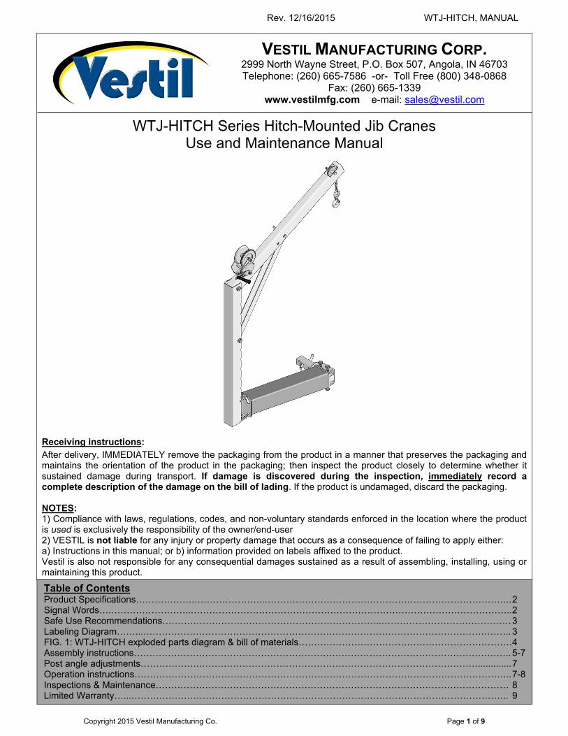
Product specifications: Dimensions and other product specifications appear in the diagrams and table below.
Model Uniform capacity
Overall width Overall length
Overall height Net weight A B
WTJ-HITCH 600 lb.
272.7kg 1913/16 in. 50.3 cm
445/16 in. 112.6 cm
401/16 in. 101.8 cm
741/4 in. 188.6 cm
128.5 lb. 58.4 kg
SIGNAL WORDS:
This manual uses SIGNAL WORDS to indicate the likelihood of personal injuries, as well as the probable seriousness of those injuries, if the product is misused in the ways described. Other signal words call attention to uses of the product likely cause property damage. The signal words used appear below along with the meaning of each word:
Identifies a hazardous situation which, if not avoided, WILL result in DEATH or SERIOUS INJURY. Use of this signal word is limited to the most extreme situations.
Identifies a hazardous situation which, if not avoided, COULD result in DEATH or SERIOUS INJURY.
Indicates a hazardous situation which, if not avoided, COULD result in MINOR or MODERATE injury.
Identifies practices likely to result in product/property damage, such as operation that might damage the product.
Each person who assembles, installs, uses, or maintains this product should read the entire manual in advance and fully understand the directions. If after reading the manual you do not understand an instruction, ask your supervisor or employer for clarification, because failure to adhere to the directions in this manual might result in serious personal injury.
Side view: Brace connected to boom at position A (see “Step 5” on p. 6)
Side and Front Views: Brace connected to boom at position B (see “Step 5” on p. 6)
Overhead view:
Rev. 12/16/2015 WTJ-HITCH, MANUAL
Copyright 2015 Vestil Manufacturing Co. Page 3 of 9
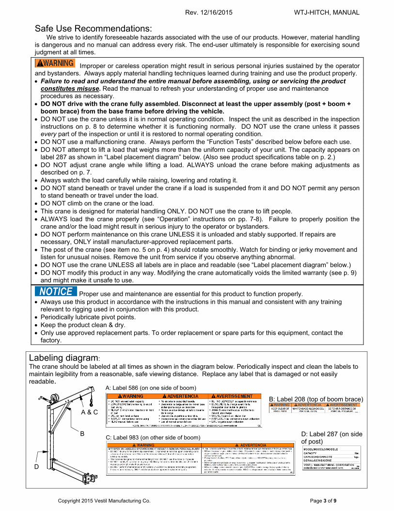
Safe Use Recommendations: We strive to identify foreseeable hazards associated with the use of our products. However, material handling
is dangerous and no manual can address every risk. The end-user ultimately is responsible for exercising sound judgment at all times.
Improper or careless operation might result in serious personal injuries sustained by the operator and bystanders. Always apply material handling techniques learned during training and use the product properly. Failure to read and understand the entire manual before assembling, using or servicing the product
constitutes misuse. Read the manual to refresh your understanding of proper use and maintenance procedures as necessary.
DO NOT drive with the crane fully assembled. Disconnect at least the upper assembly (post + boom + boom brace) from the base frame before driving the vehicle.
DO NOT use the crane unless it is in normal operating condition. Inspect the unit as described in the inspection instructions on p. 8 to determine whether it is functioning normally. DO NOT use the crane unless it passes every part of the inspection or until it is restored to normal operating condition.
DO NOT use a malfunctioning crane. Always perform the “Function Tests” described below before each use. DO NOT attempt to lift a load that weighs more than the uniform capacity of your unit. The capacity appears on
label 287 as shown in “Label placement diagram” below. (Also see product specifications table on p. 2.) DO NOT adjust crane angle while lifting a load. ALWAYS unload the crane before making adjustments as
described on p. 7. Always watch the load carefully while raising, lowering and rotating it. DO NOT stand beneath or travel under the crane if a load is suspended from it and DO NOT permit any person
to stand beneath or travel under the load. DO NOT climb on the crane or the load. This crane is designed for material handling ONLY. DO NOT use the crane to lift people. ALWAYS load the crane properly (see “Operation” instructions on pp. 7-8). Failure to properly position the
crane and/or the load might result in serious injury to the operator or bystanders. DO NOT perform maintenance on this crane UNLESS it is unloaded and stably supported. If repairs are
necessary, ONLY install manufacturer-approved replacement parts. The post of the crane (see item no. 5 on p. 4) should rotate smoothly. Watch for binding or jerky movement and
listen for unusual noises. Remove the unit from service if you observe anything abnormal. DO NOT use the crane UNLESS all labels are in place and readable (see “Label placement diagram” below.) DO NOT modify this product in any way. Modifying the crane automatically voids the limited warranty (see p. 9)
and might make it unsafe to use.
Proper use and maintenance are essential for this product to function properly. Always use this product in accordance with the instructions in this manual and consistent with any training
relevant to rigging used in conjunction with this product. Periodically lubricate pivot points. Keep the product clean & dry. Only use approved replacement parts. To order replacement or spare parts for this equipment, contact the
factory.
Labeling diagram: The crane should be labeled at all times as shown in the diagram below. Periodically inspect and clean the labels to maintain legibility from a reasonable, safe viewing distance. Replace any label that is damaged or not easily readable.
A: Label 586 (on one side of boom)
D: Label 287 (on side of post)
C: Label 983 (on other side of boom)
B: Label 208 (top of boom brace)
A & C
B
D
Rev. 12/16/2015 WTJ-HITCH, MANUAL
Copyright 2015 Vestil Manufacturing Co. Page 4 of 9
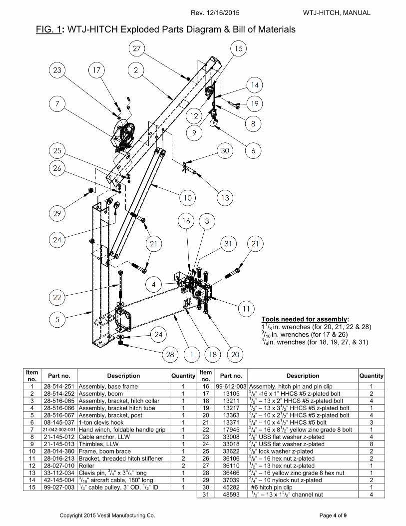
FIG. 1: WTJ-HITCH Exploded Parts Diagram & Bill of Materials
Item no.
Part no. Description Quantity Item no.
Part no. Description Quantity
1 28-514-251 Assembly, base frame 1 16 99-612-003 Assembly, hitch pin and pin clip 1 2 28-514-252 Assembly, boom 1 17 13105 3/8” -16 x 1” HHCS #5 z-plated bolt 2 3 28-516-065 Assembly, bracket, hitch collar 1 18 13211 1/2” – 13 x 2” HHCS #5 z-plated bolt 4 4 28-516-066 Assembly, bracket hitch tube 1 19 13217 1/2” – 13 x 31/2” HHCS #5 z-plated bolt 1 5 28-516-067 Assembly, bracket, post 1 20 13363 3/4” – 10 x 21/2” HHCS #5 z-plated bolt 4 6 08-145-037 1-ton clevis hook 1 21 13371 3/4” – 10 x 41/2” HHCS #5 bolt 3 7 21-042-002-001 Hand winch, foldable handle grip 1 22 17945 3/4” – 16 x 81/2” yellow zinc grade 8 bolt 1 8 21-145-012 Cable anchor, LLW 1 23 33008 3/8” USS flat washer z-plated 4 9 21-145-013 Thimbles, LLW 1 24 33018 3/4” USS flat washer z-plated 8 10 28-014-380 Frame, boom brace 1 25 33622 3/8” lock washer z-plated 2 11 28-016-213 Bracket, threaded hitch stiffener 2 26 36106 3/8” – 16 hex nut z-plated 2 12 28-027-010 Roller 2 27 36110 1/2” – 13 hex nut z-plated 1 13 33-112-034 Clevis pin, 3/4” x 33/4” long 1 28 36466 3/4” – 16 yellow zinc grade 8 hex nut 1 14 42-145-004 3/16” aircraft cable, 180” long 1 29 37039 3/4” – 10 nylock nut z-plated 2 15 99-027-003 1/4” cable pulley, 3” OD, 1/2” ID 1 30 45282 #6 hitch pin clip 1 31 48593 1/2” – 13 x 15/8” channel nut 4
Tools needed for assembly: 11/8 in. wrenches (for 20, 21, 22 & 28) 9/16 in. wrenches (for 17 & 26) 3/4in. wrenches (for 18, 19, 27, & 31)
Rev. 12/16/2015 WTJ-HITCH, MANUAL
Copyright 2015 Vestil Manufacturing Co. Page 5 of 9
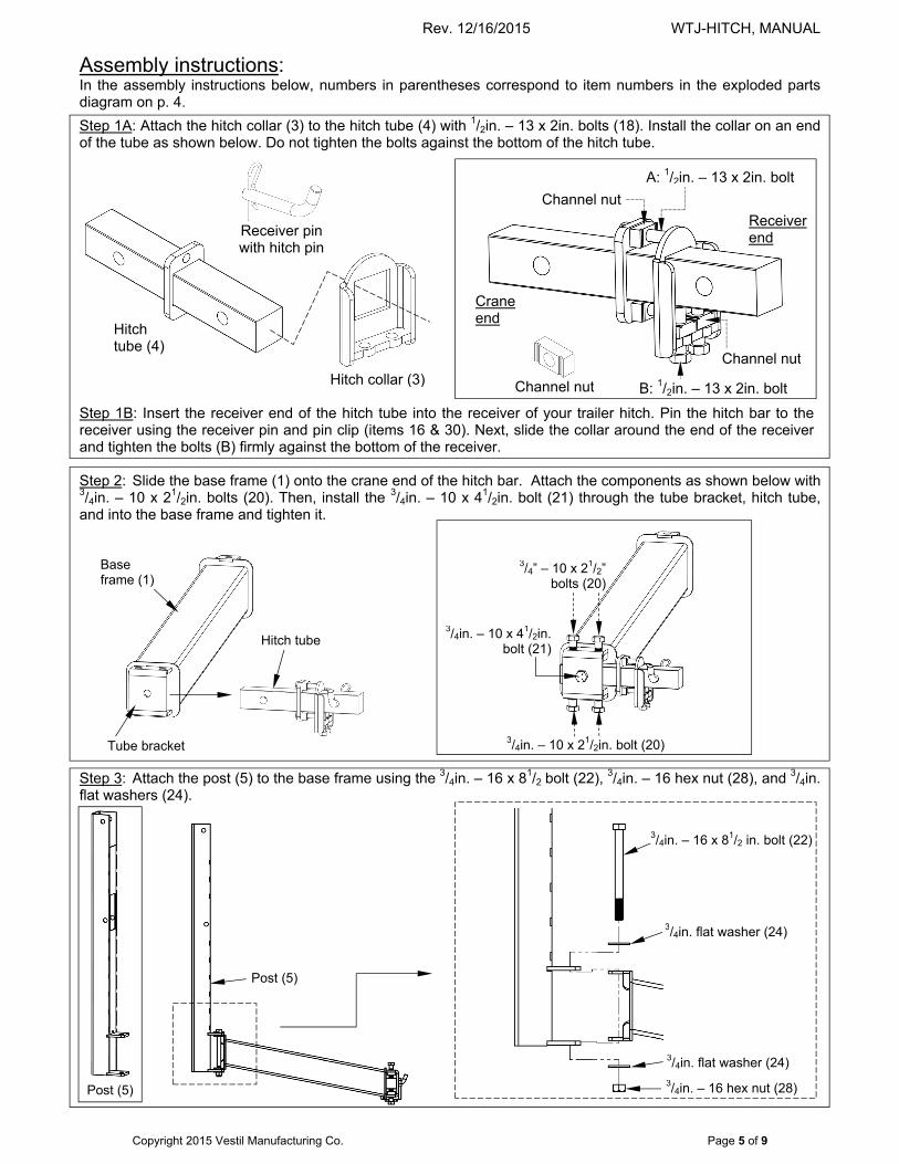
Assembly instructions: In the assembly instructions below, numbers in parentheses correspond to item numbers in the exploded parts diagram on p. 4.
Step 1A: Attach the hitch collar (3) to the hitch tube (4) with 1/2in. – 13 x 2in. bolts (18). Install the collar on an end of the tube as shown below. Do not tighten the bolts against the bottom of the hitch tube. Step 1B: Insert the receiver end of the hitch tube into the receiver of your trailer hitch. Pin the hitch bar to the receiver using the receiver pin and pin clip (items 16 & 30). Next, slide the collar around the end of the receiver and tighten the bolts (B) firmly against the bottom of the receiver. Step 2: Slide the base frame (1) onto the crane end of the hitch bar. Attach the components as shown below with 3/4in. – 10 x 21/2in. bolts (20). Then, install the 3/4in. – 10 x 41/2in. bolt (21) through the tube bracket, hitch tube, and into the base frame and tighten it.
Step 3: Attach the post (5) to the base frame using the 3/4in. – 16 x 81/2 bolt (22), 3/4in. – 16 hex nut (28), and 3/4in. flat washers (24).
B: 1/2in. – 13 x 2in. bolt
Hitch collar (3)
3/4in. – 10 x 21/2in. bolt (20)
3/4” – 10 x 21/2” bolts (20)
3/4in. – 10 x 41/2in. bolt (21)
Post (5)
Receiver end
Crane end
Tube bracket
Base frame (1)
Hitch tube (4)
Receiver pin with hitch pin
3/4in. – 16 x 81/2 in. bolt (22)
3/4in. – 16 hex nut (28)
3/4in. flat washer (24)
3/4in. flat washer (24)
Post (5)
Channel nut
Channel nut
A: 1/2in. – 13 x 2in. bolt
Channel nut
Hitch tube
Rev. 12/16/2015 WTJ-HITCH, MANUAL
Copyright 2015 Vestil Manufacturing Co. Page 6 of 9
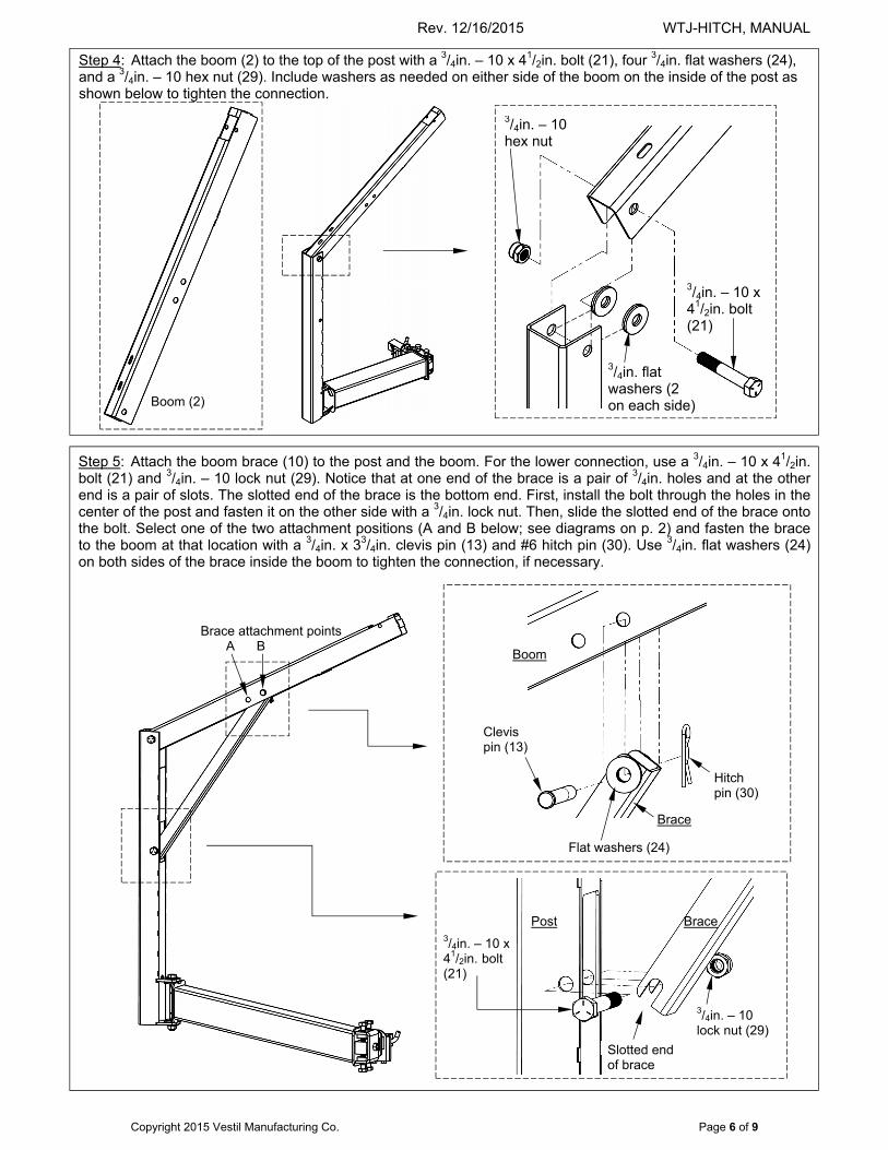
Step 5: Attach the boom brace (10) to the post and the boom. For the lower connection, use a 3/4in. – 10 x 41/2in. bolt (21) and 3/4in. – 10 lock nut (29). Notice that at one end of the brace is a pair of 3/4in. holes and at the other end is a pair of slots. The slotted end of the brace is the bottom end. First, install the bolt through the holes in the center of the post and fasten it on the other side with a 3/4in. lock nut. Then, slide the slotted end of the brace onto the bolt. Select one of the two attachment positions (A and B below; see diagrams on p. 2) and fasten the brace to the boom at that location with a 3/4in. x 33/4in. clevis pin (13) and #6 hitch pin (30). Use 3/4in. flat washers (24) on both sides of the brace inside the boom to tighten the connection, if necessary.
Step 4: Attach the boom (2) to the top of the post with a 3/4in. – 10 x 41/2in. bolt (21), four 3/4in. flat washers (24), and a 3/4in. – 10 hex nut (29). Include washers as needed on either side of the boom on the inside of the post as shown below to tighten the connection.
3/4in. – 10 x 41/2in. bolt
Boom
Slotted end of brace
Brace attachment points A B
3/4in. – 10 lock nut (29)
3/4in. – 10 x 41/2in. bolt (21)
3/4in. – 10 hex nut
3/4in. flat washers (2 on each side) Boom (2)
Hitch pin (30)
Clevis pin (13)
Flat washers (24)
3/4in. – 10 x 41/2in. bolt (21)
Post Brace
Brace
Rev. 12/16/2015 WTJ-HITCH, MANUAL
Copyright 2015 Vestil Manufacturing Co. Page 7 of 9
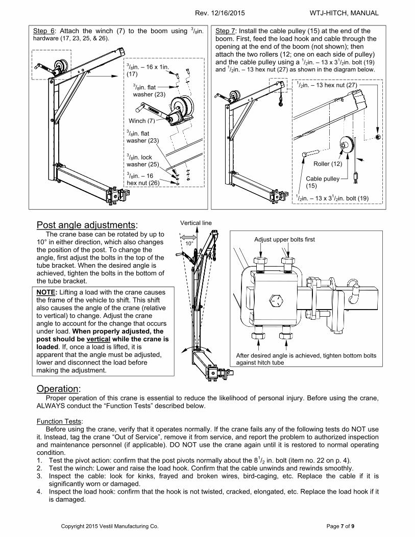
Post angle adjustments: The crane base can be rotated by up to
10° in either direction, which also changes the position of the post. To change the angle, first adjust the bolts in the top of the tube bracket. When the desired angle is achieved, tighten the bolts in the bottom of the tube bracket.
Operation:
Proper operation of this crane is essential to reduce the likelihood of personal injury. Before using the crane, ALWAYS conduct the “Function Tests” described below.
Function Tests:
Before using the crane, verify that it operates normally. If the crane fails any of the following tests do NOT use it. Instead, tag the crane “Out of Service”, remove it from service, and report the problem to authorized inspection and maintenance personnel (if applicable). DO NOT use the crane again until it is restored to normal operating condition. 1. Test the pivot action: confirm that the post pivots normally about the 81/2 in. bolt (item no. 22 on p. 4). 2. Test the winch: Lower and raise the load hook. Confirm that the cable unwinds and rewinds smoothly. 3. Inspect the cable: look for kinks, frayed and broken wires, bird-caging, etc. Replace the cable if it is
significantly worn or damaged. 4. Inspect the load hook: confirm that the hook is not twisted, cracked, elongated, etc. Replace the load hook if it
is damaged.
Step 7: Install the cable pulley (15) at the end of the boom. First, feed the load hook and cable through the opening at the end of the boom (not shown); then attach the two rollers (12; one on each side of pulley) and the cable pulley using a 1/2in. – 13 x 31/2in. bolt (19) and 1/2in. – 13 hex nut (27) as shown in the diagram below.
Step 6: Attach the winch (7) to the boom using 3/8in. hardware (17, 23, 25, & 26).
3/8in. flat washer (23)
3/8in. – 16 x 1in. (17)
Winch (7)
10° Adjust upper bolts first
After desired angle is achieved, tighten bottom bolts against hitch tube
NOTE: Lifting a load with the crane causes the frame of the vehicle to shift. This shift also causes the angle of the crane (relative to vertical) to change. Adjust the crane angle to account for the change that occurs under load. When properly adjusted, the post should be vertical while the crane is loaded. If, once a load is lifted, it is apparent that the angle must be adjusted, lower and disconnect the load before making the adjustment.
Vertical line
Cable pulley (15)
Roller (12)
1/2in. – 13 x 31/2in. bolt (19)
1/2in. – 13 hex nut (27)
3/8in. – 16 hex nut (26)
3/8in. flat washer (23)
3/8in. lock washer (25)
Rev. 12/16/2015 WTJ-HITCH, MANUAL
Copyright 2015 Vestil Manufacturing Co. Page 8 of 9
Proper loading: Before using the crane, prepare the vehicle. Park the vehicle on level ground and engage the parking brake. If you
will use the crane on a pickup truck, it might be necessary to lower or remove the tailgate to accommodate the load. Recall that the boom brace can be attached to the boom at either of 2 positions (see Step 5 on p. 6). Attaching the brace to position A will allow you to raise loads as high as possible. Attachment to position B optimizes boom reach (horizontal distance) but does not allow loads to be lifted as high. Select the appropriate attachment point for the brace and then proceed to the next step.
Next, bring the load to the vehicle. Rotate the boom away from the vehicle and position the load directly below the load hook. Attach necessary rigging to the load; then attach the load hook to the rigging.
Slowly raise the load off of the ground with the winch. Observe both the crane and the load as the load rises. Make sure that the load does not swing, because the post will tilt slightly under the weight of a load. Observe the crane post and make sure that it is substantially vertical while the load is applied. When the load is adequately elevated, slowly push the load into the vehicle and lower it until it is fully supported by the vehicle. Next, disconnect the load hook from the rigging and turn the winch until the hook is fully retracted.
Do not drive while the crane is attached to the vehicle. Either disconnect the entire crane assembly by pulling the hitch tube out of the receiver or remove the 81/2in. bolt (22) that fastens the upper assembly (post, boom, and brace) to the base frame.
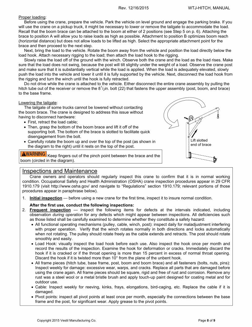
Lowering the tailgate: The tailgate of some trucks cannot be lowered without contacting the boom brace. The crane is designed to address this issue without having to disconnect hardware:
First, retract the load cable; Then, grasp the bottom of the boom brace and lift it off of the
supporting bolt. The bottom of the brace is slotted to facilitate quick disengagement from the bolt.
Carefully rotate the boom up and over the top of the post (as shown in the diagram to the right) until it rests on the top of the post.
Keep fingers out of the pinch point between the brace and the boom (circled in the diagram).
Inspections and Maintenance Crane owners and operators should regularly inspect this crane to confirm that it is in normal working
condition. Occupational Safety and Health Administration (OSHA) crane inspection procedures appear in 29 CFR 1910.179 (visit http://www.osha.gov/ and navigate to “Regulations” section 1910.179; relevant portions of those procedures appear in paraphrase below).
1. Initial inspection — before using a new crane for the first time, inspect it to insure normal condition.
After the first use, conduct the following inspections: 2. Frequent inspection — inspect the following items for defects at the intervals indicated, including
observation during operation for any defects which might appear between inspections. All deficiencies such as those listed shall be carefully examined to determine whether they constitute a safety hazard: All functional operating mechanisms (pulley, cable, winch, post): inspect daily for maladjustment interfering
with proper operation. Verify that the winch rotates normally in both directions and locks automatically when not rotating. The pulley should rotate freely as the cable extends and retracts. The post should rotate smoothly and easily.
Load Hook: visually inspect the load hook before each use. Also inspect the hook once per month and record the results of the inspection. Examine the hook for deformation or cracks. Immediately discard the hook if it is cracked or if the throat opening is more than 15 percent in excess of normal throat opening. Discard the hook if it is twisted more than 10° from the plane of the unbent hook.
All frame pieces (hitch tube, base frame, post, boom and boom brace) and all fasteners (bolts, nuts, pins): Inspect weekly for damage: excessive wear, warps, and cracks. Replace all parts that are damaged before using the crane again. All frame pieces should be square, rigid and free of rust and corrosion. Remove any rust was a steel wool or a metal bristle brush and apply touch-up paint designed for coating metal and for outdoor use.
Cable: Inspect weekly for reeving, kinks, frays, elongations, bird-caging, etc. Replace the cable if it is damaged.
Pivot points: inspect all pivot points at least once per month, especially the connections between the base frame and the post, for significant wear. Apply grease to the pivot points.
Lift slotted end of brace
Rev. 12/16/2015 WTJ-HITCH, MANUAL
Copyright 2015 Vestil Manufacturing Co. Page 9 of 9
LIMITED WARRANTY
Vestil Manufacturing Corporation (“Vestil”) warrants this product to be free of defects in material and workmanship during the warranty period. Our warranty obligation is to provide a replacement for a defective original part if the part is covered by the warranty, after we receive a proper request from the warrantee (you) for warranty service.
Who may request service? Only a warrantee may request service. You are a warrantee if you purchased the product from Vestil or from an authorized distributor AND Vestil has been fully paid.
What is an “original part”? An original part is a part used to make the product as shipped to the warrantee.
What is a “proper request”? A request for warranty service is proper if Vestil receives: 1) a photocopy of the Customer Invoice that displays the shipping date; AND 2) a written request for warranty service including your name and phone number. Send requests by any of the following methods:
Mail Fax Email Vestil Manufacturing Corporation (260) 665-1339 [email protected] 2999 North Wayne Street, PO Box 507 Phone Angola, IN 46703 (260) 665-7586
In the written request, list the parts believed to be defective and include the address where replacements should be delivered.
What is covered under the warranty? After Vestil receives your request for warranty service, an authorized representative will contact you to determine whether your claim is covered by the warranty. Before providing warranty service, Vestil may require you to send the entire product, or just the defective part or parts, to its facility in Angola, IN. The warranty covers defects in the following original dynamic components: motors, hydraulic pumps, electronic controllers, switches and cylinders. It also covers defects in original parts that wear under normal usage conditions (“wearing parts”), such as bearings, hoses, wheels, seals, brushes, and batteries.
How long is the warranty period? The warranty period for original dynamic components is 90 days. For wearing parts, the warranty period is 90 days. The warranty periods begin on the date when Vestil ships the product to the warrantee. If the product was purchased from an authorized distributor, the periods begin when the distributor ships the product. Vestil may, at its sole discretion, extend the warranty periods for products shipped from authorized distributors by up to 30 days to account for shipping time.
If a defective part is covered by the warranty, what will Vestil do to correct the problem? Vestil will provide an appropriate replacement for any covered part. An authorized representative of Vestil will contact you to discuss your claim.
What is not covered by the warranty? 1. Labor; 2. Freight; 3. Occurrence of any of the following, which automatically voids the warranty:
Product misuse; Negligent operation or repair; Corrosion or use in corrosive conditions; Inadequate or improper maintenance; Damage sustained during shipping; Accidents involving the product; Unauthorized modifications: DO NOT modify the product IN ANY WAY without first receiving
written authorization from Vestil. Modification(s) might make the product unsafe to use or might cause excessive and/or abnormal wear.
Do any other warranties apply to the product? Vestil Manufacturing Corp. makes no other express warranties. All implied warranties are disclaimed to the extent allowed by law. Any implied warranty not disclaimed is limited in scope to


![Pillar and wall-mounted slewing jib cranes · Max. load capacity [kg] Electric slewing Pillar-mounted slewing jib cranes Wall-mounted slewing jib cranes Jib type/design Max. outreach](https://img.pdfslide.net/doc/110x75/5b535fa87f8b9ae30b8be93d/pillar-and-wall-mounted-slewing-jib-cranes-max-load-capacity-kg-electric.jpg)