Embed Size (px)
Citation preview
XBLUE Networks X16
Installation Guide
X16 Installation Guide
- 2 - Issue 2
Part N
um
bers
Revision Table Revision Description of Changes Date Released
Issue 2– PAL This manual supersedes all previously released manuals 06/09
Page 6 – added a page brake to change the page tab labels.
Page 12 – Fixed typo in Installation
Page 14 – Fixed typo line up to lineup
Page 16 – Fixed typo in Cable Pair
Page 20 – Fixed typo on endpoint device
Page 35 – Fixed typo, added a “,” to sentence
Page 22 – Entered new LIU functionality
Page 29 – Fixed typo in Muted Ring
Page 29 – Fixed typo in New Message Playback
Page 32 – Fixed typo in Transfer
Page 56 – Fixed typo in One Touch Record
Page 57 – Fixed typos in Using AME
1/14/08
Preliminary Release – PAL 11/2007
Part Numbers
Part Numbers Description 1610-00 X16 Voice Server
1630-00 2 CO Line Expansion Module
1670-00 Backlit digital telephone endpoint – Charcoal
1670-92 Backlit digital telephone endpoint – XBLUE
1670-86 Backlit digital telephone endpoint – Titanium Metallic
1670-76 Backlit digital telephone endpoint – Red Mahogany
1675-00 Endpoint device
Reproduction, publication, or duplication of this manual, or any part thereof, in any
manner, mechanically, electronically, or photographically, is strictly prohibited.
© Copyright 2006 by XBLUE Network, LLC. All rights reserved.
The information contained in this document is subject to change without notice and should
not be construed as a commitment by XBLUE Networks, LLC,; XBLUE Networks, reserves
the right, without notice, to make changes to equipment design as advances in engineering
and manufacturing methods warrant.
Any and all toll charges are the sole responsibility of the user of the installed equipment;
XBLUE offers no warranty or will assume any responsibility for any toll charges.
Trademarks: XBLUE, XBLUE Networks, X16 are trademarks of XBLUE Networks, LLC. All trademarks are the property of their respective owners.
Issue 2 - 3 -
Table
of
Conte
nts
Table of Contents
PART NUMBERS ....................................................................... 2
TABLE OF CONTENTS .............................................................. 3
NOTICES ................................................................................. 7
HEARING AID COMPATIBILITY: ................................................... 7 UL/CSA SAFETY COMPLIANCE: ................................................... 7 FCC INFORMATION .................................................................. 8
NOTES: ................................................................................... 8
INTRODUCTION ...................................................................... 9
FEATURES ............................................................................... 9
GETTING TO KNOW THE X16 TELEPHONE .............................. 10
THE X16 TELEPHONE DISPLAY ................................................. 10 DEFAULT BUTTON LAYOUT ....................................................... 11 NAVIGATION KEYS ................................................................. 11
SYSTEM CONFIGURATION ...................................................... 12
INSTALLATION ...................................................................... 13 Step 1 - Location ...................................................................... 13 Step 2 – CO Line Connections .................................................... 14 Step 3 – Telephone Endpoint Connection ................................... 15 X16 Cable Pair .......................................................................... 17
ENDPOINT DEVICE ................................................................ 18
PUNCH DOWN ....................................................................... 19
Step 4 – Power up and Initialization ........................................... 20 Step 5 – Extension Numbering ................................................... 20
2 CO LINE EXPANSION MODULE ............................................. 21
Step 1 – Installing the Expansion Module ................................... 21 Step 2 – Insert the Expansion Module ........................................ 22
X16 Installation Guide
- 4 - Issue 2
Table
of C
onten
ts
TELEPHONE WALL MOUNT ..................................................... 22
FEATURE DESCRIPTION ......................................................... 23
ALL PAGE ............................................................................ 23 ANSWERING MACHINE EMULATION ............................................ 23 AUTO ATTENDANT - VOICE MAIL (STANDARD) .............................. 23 BACKLIT BLUE LCD DISPLAY WITH POWER SAVER MODE ................. 24 CALL PICK UP ....................................................................... 24 CALL TIMER ......................................................................... 24 CALLER ID AND CALL WAITING CALLER ID (TYPE 1 & TYPE 2) ......... 24 CALLER ID ENABLE/DISABLE .................................................... 24 CO LINE BUSY/IDLE STATUS (LED) ........................................... 25 CO LINE RINGING – PER EXTENSION ......................................... 25 CONFERENCE (3-WAY) ............................................................ 25 CONFERENCE – EXPRESS CONFERENCE ........................................ 26 CONVERSATION RECORDING – VOICE MAIL (STANDARD) ................. 26 DAYLIGHT SAVINGS – AUTOMATIC (USING CID) ........................... 26 DIRECT CO LINE ACCESS ........................................................ 26 DIRECT MAILBOX TRANSFER - VOICE MAIL (STANDARD) ................. 27 DIRECT STATION SELECT (DSS) – BUSY LAMP FIELD (BLF) ............. 27 DISTINCTIVE RINGING – RINGER TYPE ....................................... 27 DO NOT DISTURB (DND) ........................................................ 27 FLASH ................................................................................ 28 FLASH TIMER ....................................................................... 28 FORWARD ........................................................................... 28 HANDS-FREE CALLING ............................................................ 29 HANDSET/HEADSET VOLUME CONTROL ....................................... 29 HEADSET ACTIVATION ............................................................ 30 HOLD ................................................................................. 30 HOT DIAL PAD...................................................................... 30 INTERCOM CALLING ............................................................... 30 INTERCOM PAGING ................................................................ 30 LINE STATUS DETECTION (LINE IN USE) ..................................... 30 MEMO RECORDING - VOICE MAIL (STANDARD) ............................. 31 MESSAGE WAITING (TELEPHONE COMPANY-FSK) .......................... 31
Issue 2 - 5 -
Table
of
Conte
nts
MULTILINGUAL DISPLAY PER EXTENSION ..................................... 31 MUSIC ON HOLD INPUT ........................................................... 31 MUTE WITH LED INDICATION ................................................... 32 MUTED RING (RING ALERT) ..................................................... 32 NAVIGATION KEYS ................................................................. 32 NEW MESSAGE PLAYBACK - VOICE MAIL (STANDARD) ..................... 32 PAGING .............................................................................. 32 MEET ME ANSWER (PAGING) ................................................... 32 PAUSE ................................................................................ 33 PERSONAL MAILBOX - VOICE MAIL (STANDARD) ............................ 33 PHONE BOOK DIALING ............................................................ 33 PRIVACY (PRIVACY RELEASE) ................................................... 33 PROGRAMMABLE BUTTONS (12) ................................................ 33 PROGRAMMABLE PAUSE (SPEED DIAL BINS) ................................. 33 REDIAL (LAST 6 NUMBER REDIAL) ............................................. 33 RING ALERT (MUTED RINGING) ................................................ 34 RINGING (AUDIBLE AND VISUAL) ............................................... 34 RINGER VOLUME CONTROL ...................................................... 34 ROOM MONITOR ................................................................... 34 SETTING TIME AND DATE (AUTOMATIC) ...................................... 34 SET RELOCATION .................................................................. 34 SPEAKERPHONE (DIGITAL TELEPHONE ENDPOINT) WITH LED ........... 35 SPEED DIAL BINS .................................................................. 35 TIME IN DISPLAY ................................................................... 35 TONE/PULSE ........................................................................ 35 TRANSFER ........................................................................... 35 TRANSFER – DIRECT TO VOICE MAIL .......................................... 35 VOLUME ADJUSTMENTS ........................................................... 35 VOICE MAIL (STANDARD) ........................................................ 36 WAITING TIME ..................................................................... 36
PROGRAMMING ..................................................................... 37
NAVIGATION KEYS ................................................................ 38
PHONE SETUP PARAMETERS ..................................................... 38
X16 Installation Guide
- 6 - Issue 2
Table
of C
onten
ts
PHONE SETUP ....................................................................... 39
PROGRAMMING FEATURE BUTTONS ............................................ 44 FEATURE BUTTON PROGRAMMING .............................................. 45
SYSTEM SETUP ..................................................................... 47
PROGRAMMING GUIDE .......................................................... 53
RINGING SCENARIOS ............................................................ 56
AUTO ATTENDANT ................................................................. 56 All Extensions Ringing Off .......................................................... 56 All Extensions Ringing On .......................................................... 56 AA Only .................................................................................... 56 Ringing..................................................................................... 56 Common Ringing ...................................................................... 56
FUNCTIONS .......................................................................... 57
Features and LED function ......................................................... 57 Lamp (LED) Cadence ................................................................. 57 Lamp (LED)s on Phone .............................................................. 57 Intercom Tone cadences ........................................................... 57 CO Line Cadence and Status Table ............................................. 58 Ringing Cadence ....................................................................... 58 Cable Specifications .................................................................. 58
TROUBLESHOOTING .............................................................. 59
IDLE LCD DISPLAY ................................................................ 60
VOICE MAIL OPERATION ........................................................ 61
AUTO ATTENDANT ................................................................. 61 PERSONAL MAILBOX ............................................................... 61 MEMO RECORDING ................................................................ 61 ONE TOUCH RECORD ............................................................. 61
Answering Machine Emulation (AME) ......................................... 62 Playing New Messages .............................................................. 62 Deleting Messages .................................................................... 63 Voice Mailbox Quick Start Guide ................................................. 63
Issue 2 - 7 -
Notice
s
Getting Started: ........................................................................ 63
REMOTE COMMANDS ............................................................. 65
REMOTE ACCESS ................................................................... 65
INDEX .................................................................................. 66
NOTES: ................................................................................. 69
NOTES: ................................................................................. 70
NOTES: ................................................................................. 71
Notices
Hearing Aid Compatibility:
The digital telephone endpoints are hearing aid compatible, as defined in section 68.316 of Part 68 FCC
Rules and Regulations.
UL/CSA Safety Compliance:
The X16 system has met all safety requires, and found to be in compliance with the Underwriters
Laboratories (UL) 60950-1.
Warning: This service information is designed for experienced repair technicians only and is not
designed for use by the general public. It does not contain warnings or cautions to advise non-technical
individuals of potential dangers in attempting to service a product. Products powered by electricity
should be serviced or repaired only by experienced professional technicians. Any attempt to service or
repair the product or products dealt with in this service information by anyone else could result in
serious injury or death.
This equipment generates, uses, and can radiate radio frequency energy, and if not installed and used
properly, that is, in strict accordance with the instruction manual, may cause interference to radio and
television reception. This equipment has been tested and found to comply with the limits for a Class B
computing device in Subject J of Part 15 of FCC Rules, which are designed to provide reasonable pro-
tection against such interference. However, there is no guarantee, or warranty, that interference will not
occur in a particular installation. If this equipment causes interference or fails to operate correctly, due
X16 Installation Guide
- 8 - Issue 2
Note
s:
to radio frequency interference (RFI) or electromagnetic interference (EMI), it will be fixed at the
owners‟ expense.
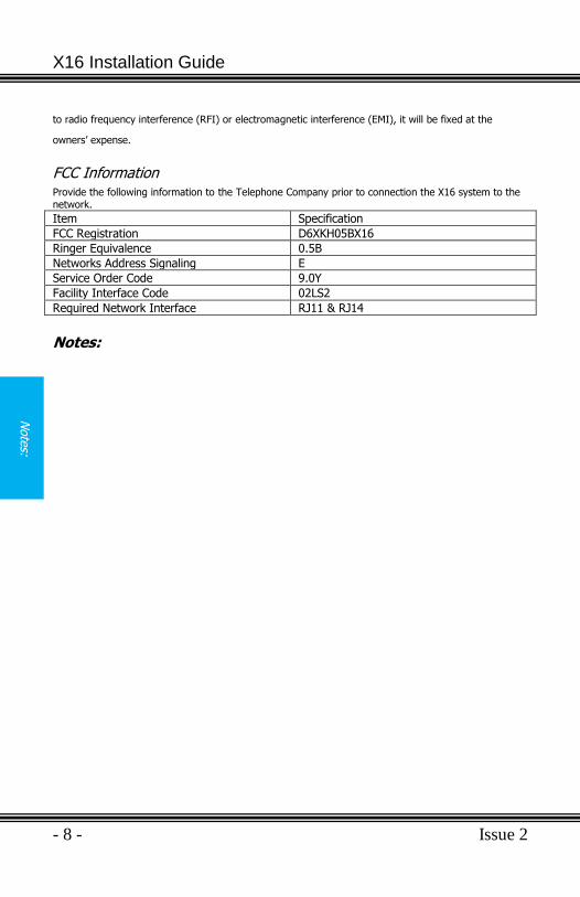
FCC Information Provide the following information to the Telephone Company prior to connection the X16 system to the network.
Item Specification
FCC Registration D6XKH05BX16
Ringer Equivalence 0.5B
Networks Address Signaling E
Service Order Code 9.0Y
Facility Interface Code 02LS2
Required Network Interface RJ11 & RJ14
Notes:
Issue 2 - 9 -
Intr
oduct
ion
Introduction
The X16 system is a full featured, next generation, multi-line business
telephone system ideal for both a home and small office environments. It comes equipped to interface with 4 Central Office (CO) Lines, with caller ID and Call Waiting Caller ID, and sixteen (16) X16 digital telephone endpoints.
The system can be expanded to accommodate two (2) additional CO Lines,
allowing for a maximum configuration of six CO Lines. In addition, the system comes standard with Auto Attendant and all X16 digital telephone
endpoints have a personal digitally integrated voice mailbox.
Features
Auto Attendant (Standard) Intercom Calling
Answering Machine Emulation Intercom Paging
Audible and Visual Ringing Meet me Answer (Paging)
Backlit LCD Display with Power saver mode
Memo Recording
Call Timer Message Waiting (Telco-FSK)
Call Transfer Multilingual Display per Extension
Caller ID and Call Waiting Caller ID Music on Hold Internal/External
Caller ID Enable/Disable per extension Mute with LED indication
CO Line Busy/Idle Status (LED) Navigation Keys
CO Line Ringing (programmable) New/All Message Play
Conference (3-way) Phone Book Dialing
Conversation Recording Programmable Buttons (12)
Daylight Savings (Automatic with Caller ID)
Programmable Pause (Speed Bins)
Direct Mailbox Transfer Redial
Direct Station Select (DSS) - Busy Lamp Field (BLF)
Remote Message Pickup
Display Number Dial Ringer Volume Control
Distinctive Ringing Set Time and Date
Do Not Disturb Speakerphone with LED
Flash Timer Speed Dial Buttons
Handset/Headset Volume Control Time in Display
Headset Activation Tone/Pulse
Holiday Operating Mode Voicemail (standard)
Hold Weekend Operating Mode
X16 Installation Guide
- 10 - Issue 2
Gettin
g to
Know
the
X16 T
ele
phone
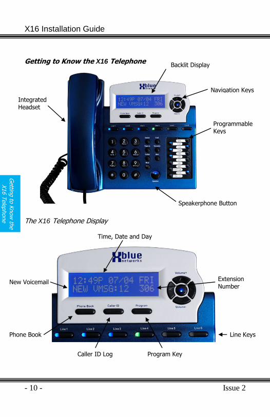
Getting to Know the X16 Telephone
The X16 Telephone Display
Time, Date and Day
Line Keys
Program Key Caller ID Log
Phone Book
New Voicemail Extension Number
Integrated Headset
Backlit Display
Navigation Keys
Programmable Keys
Speakerphone Button
Issue 2 - 11 -
Gett
ing t
o K
now
the
X16 T
ele
phone
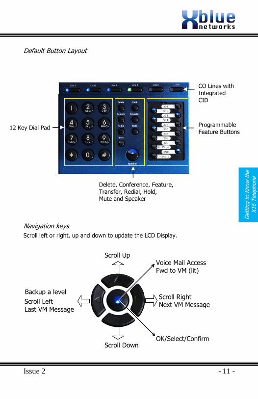
Default Button Layout
Navigation keys
Scroll left or right, up and down to update the LCD Display.
CO Lines with Integrated CID
Programmable
Feature Buttons
Delete, Conference, Feature, Transfer, Redial, Hold, Mute and Speaker
12 Key Dial Pad
Scroll Up
Scroll Down
Backup a level
Scroll Left
Last VM Message
Scroll Right Next VM Message
OK/Select/Confirm
Voice Mail Access Fwd to VM (lit)
X16 Installation Guide
- 12 - Issue 2
Syste
m
Config
ura
tion
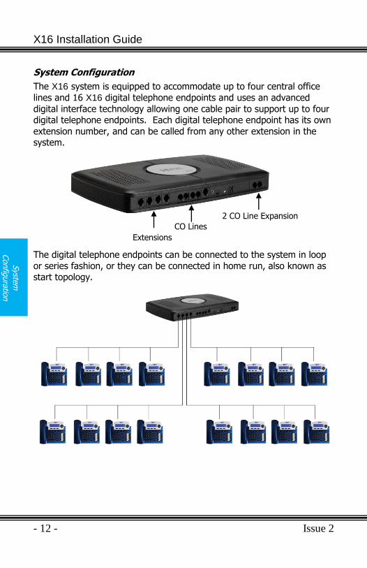
System Configuration
The X16 system is equipped to accommodate up to four central office
lines and 16 X16 digital telephone endpoints and uses an advanced
digital interface technology allowing one cable pair to support up to four digital telephone endpoints. Each digital telephone endpoint has its own
extension number, and can be called from any other extension in the system.
The digital telephone endpoints can be connected to the system in loop
or series fashion, or they can be connected in home run, also known as start topology.
Extensions
CO Lines
2 CO Line Expansion
Issue 2 - 13 -
Sys
tem
Configura
tion
Installation
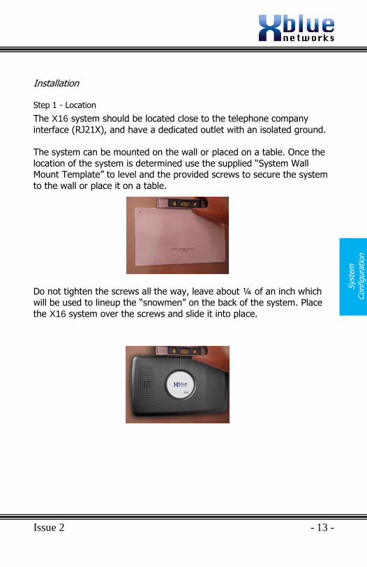
Step 1 - Location
The X16 system should be located close to the telephone company
interface (RJ21X), and have a dedicated outlet with an isolated ground.
The system can be mounted on the wall or placed on a table. Once the
location of the system is determined use the supplied “System Wall Mount Template” to level and the provided screws to secure the system
to the wall or place it on a table.
Do not tighten the screws all the way, leave about ¼ of an inch which will be used to lineup the “snowmen” on the back of the system. Place
the X16 system over the screws and slide it into place.
X16 Installation Guide
- 14 - Issue 2
Syste
m
Config
ura
tion
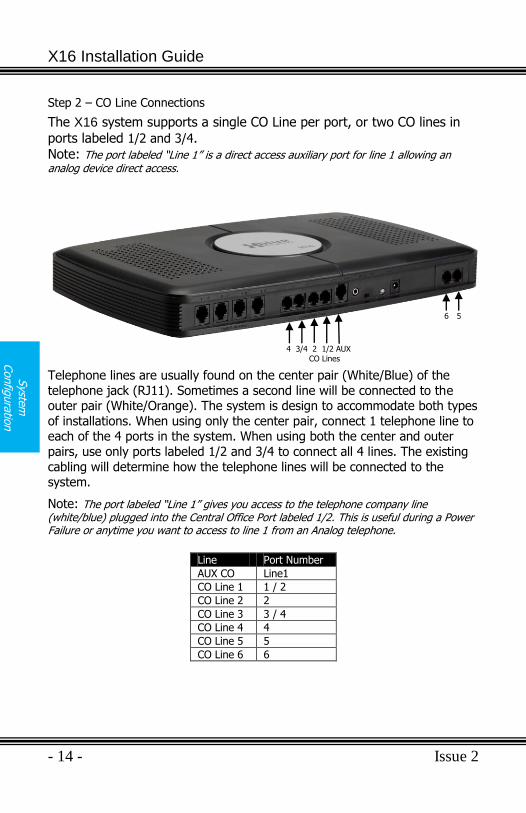
Step 2 – CO Line Connections
The X16 system supports a single CO Line per port, or two CO lines in
ports labeled 1/2 and 3/4. Note: The port labeled “Line 1” is a direct access auxiliary port for line 1 allowing an analog device direct access.
Telephone lines are usually found on the center pair (White/Blue) of the
telephone jack (RJ11). Sometimes a second line will be connected to the outer pair (White/Orange). The system is design to accommodate both types
of installations. When using only the center pair, connect 1 telephone line to each of the 4 ports in the system. When using both the center and outer
pairs, use only ports labeled 1/2 and 3/4 to connect all 4 lines. The existing
cabling will determine how the telephone lines will be connected to the system.
Note: The port labeled “Line 1” gives you access to the telephone company line (white/blue) plugged into the Central Office Port labeled 1/2. This is useful during a Power Failure or anytime you want to access to line 1 from an Analog telephone.
Line Port Number
AUX CO Line1
CO Line 1 1 / 2
CO Line 2 2
CO Line 3 3 / 4
CO Line 4 4
CO Line 5 5
CO Line 6 6
4 3/4 2 1/2 AUX
CO Lines
6 5
Issue 2 - 15 -
Sys
tem
Configura
tion
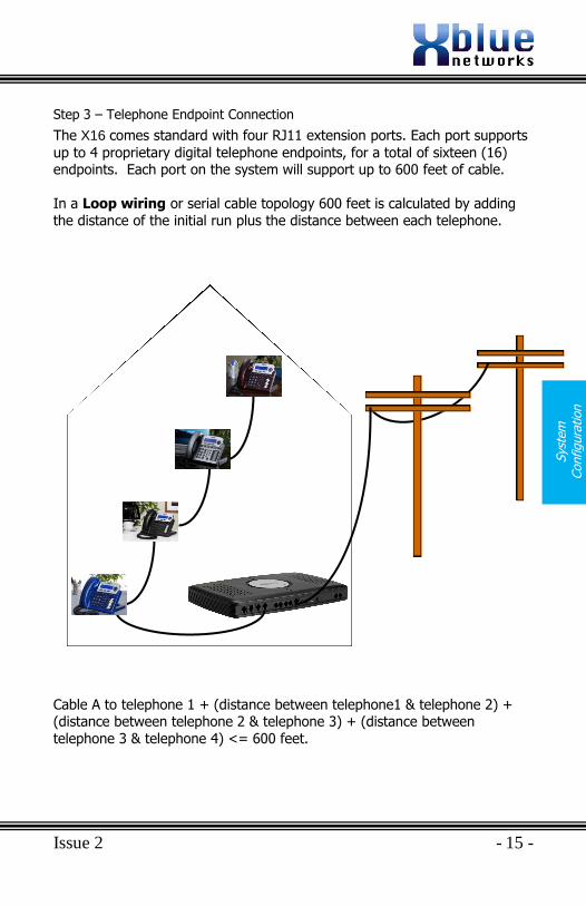
Step 3 – Telephone Endpoint Connection
The X16 comes standard with four RJ11 extension ports. Each port supports
up to 4 proprietary digital telephone endpoints, for a total of sixteen (16) endpoints. Each port on the system will support up to 600 feet of cable.
In a Loop wiring or serial cable topology 600 feet is calculated by adding
the distance of the initial run plus the distance between each telephone.
Cable A to telephone 1 + (distance between telephone1 & telephone 2) + (distance between telephone 2 & telephone 3) + (distance between
telephone 3 & telephone 4) <= 600 feet.
X16 Installation Guide
- 16 - Issue 2
Syste
m
Config
ura
tion
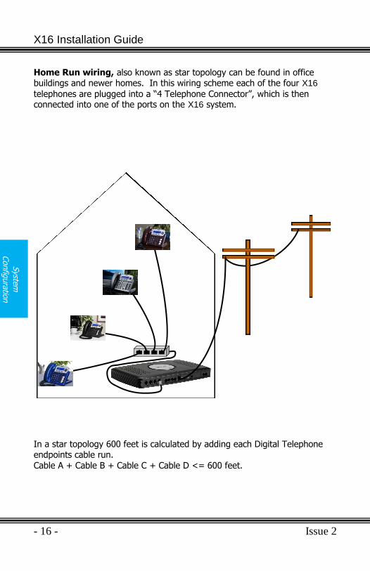
Home Run wiring, also known as star topology can be found in office buildings and newer homes. In this wiring scheme each of the four X16
telephones are plugged into a “4 Telephone Connector”, which is then connected into one of the ports on the X16 system.
In a star topology 600 feet is calculated by adding each Digital Telephone endpoints cable run.
Cable A + Cable B + Cable C + Cable D <= 600 feet.
Issue 2 - 17 -
Sys
tem
Configura
tion
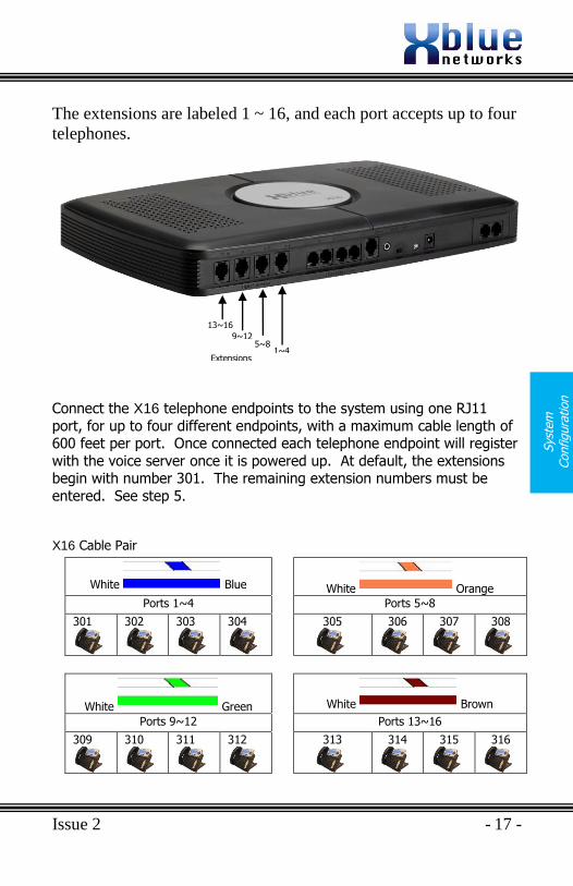
The extensions are labeled 1 ~ 16, and each port accepts up to four
telephones.
Connect the X16 telephone endpoints to the system using one RJ11
port, for up to four different endpoints, with a maximum cable length of 600 feet per port. Once connected each telephone endpoint will register
with the voice server once it is powered up. At default, the extensions begin with number 301. The remaining extension numbers must be
entered. See step 5.
X16 Cable Pair
White Blue
White Orange
Ports 1~4 Ports 5~8
301
302
303
304
305
306
307
308
White Green
White Brown
Ports 9~12 Ports 13~16
309
310
311
312
313
314
315
316
Extensions
13~16
9~12 5~8
1~4
X16 Installation Guide
- 18 - Issue 2
Endpoin
t Device
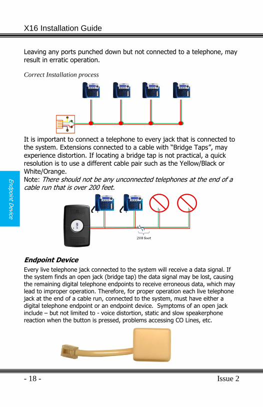
Leaving any ports punched down but not connected to a telephone, may
result in erratic operation. Correct Installation process
It is important to connect a telephone to every jack that is connected to the system. Extensions connected to a cable with “Bridge Taps”, may
experience distortion. If locating a bridge tap is not practical, a quick resolution is to use a different cable pair such as the Yellow/Black or
White/Orange.
Note: There should not be any unconnected telephones at the end of a cable run that is over 200 feet.
Endpoint Device
Every live telephone jack connected to the system will receive a data signal. If the system finds an open jack (bridge tap) the data signal may be lost, causing the remaining digital telephone endpoints to receive erroneous data, which may lead to improper operation. Therefore, for proper operation each live telephone jack at the end of a cable run, connected to the system, must have either a digital telephone endpoint or an endpoint device. Symptoms of an open jack
include – but not limited to - voice distortion, static and slow speakerphone reaction when the button is pressed, problems accessing CO Lines, etc.
Issue 2 - 19 -
Punch
Dow
n
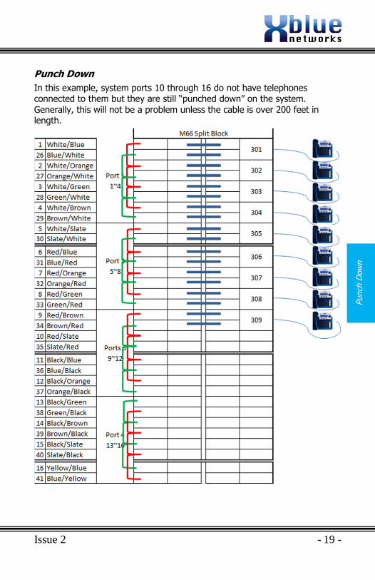
Punch Down
In this example, system ports 10 through 16 do not have telephones connected to them but they are still “punched down” on the system.
Generally, this will not be a problem unless the cable is over 200 feet in length.
X16 Installation Guide
- 20 - Issue 2
Punch
Dow
n
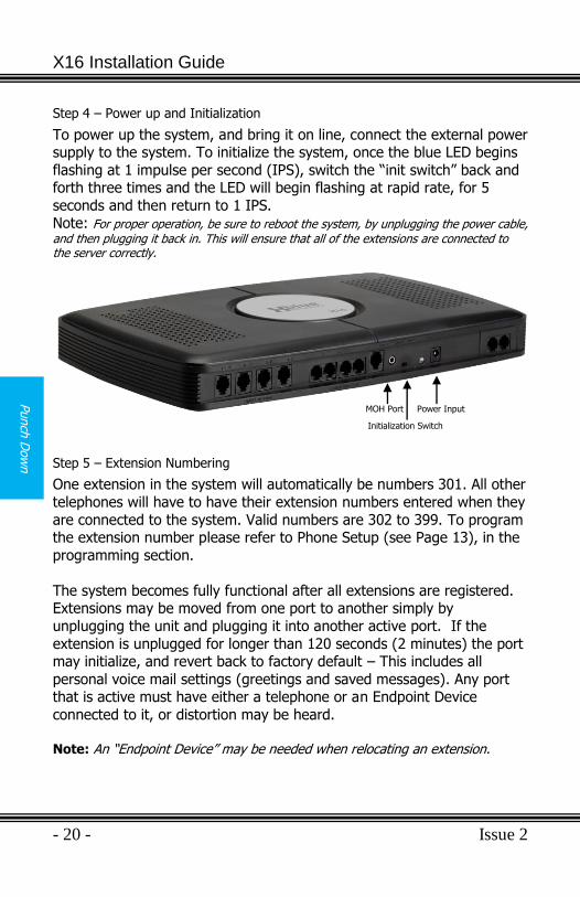
Step 4 – Power up and Initialization
To power up the system, and bring it on line, connect the external power supply to the system. To initialize the system, once the blue LED begins
flashing at 1 impulse per second (IPS), switch the “init switch” back and forth three times and the LED will begin flashing at rapid rate, for 5
seconds and then return to 1 IPS. Note: For proper operation, be sure to reboot the system, by unplugging the power cable, and then plugging it back in. This will ensure that all of the extensions are connected to the server correctly.
Step 5 – Extension Numbering
One extension in the system will automatically be numbers 301. All other
telephones will have to have their extension numbers entered when they
are connected to the system. Valid numbers are 302 to 399. To program the extension number please refer to Phone Setup (see Page 13), in the
programming section.
The system becomes fully functional after all extensions are registered. Extensions may be moved from one port to another simply by
unplugging the unit and plugging it into another active port. If the
extension is unplugged for longer than 120 seconds (2 minutes) the port may initialize, and revert back to factory default – This includes all
personal voice mail settings (greetings and saved messages). Any port that is active must have either a telephone or an Endpoint Device
connected to it, or distortion may be heard.
Note: An “Endpoint Device” may be needed when relocating an extension.
Initialization Switch
MOH Port Power Input
Issue 2 - 21 -
2 C
O L
ine
Exp
ansi
on M
odule
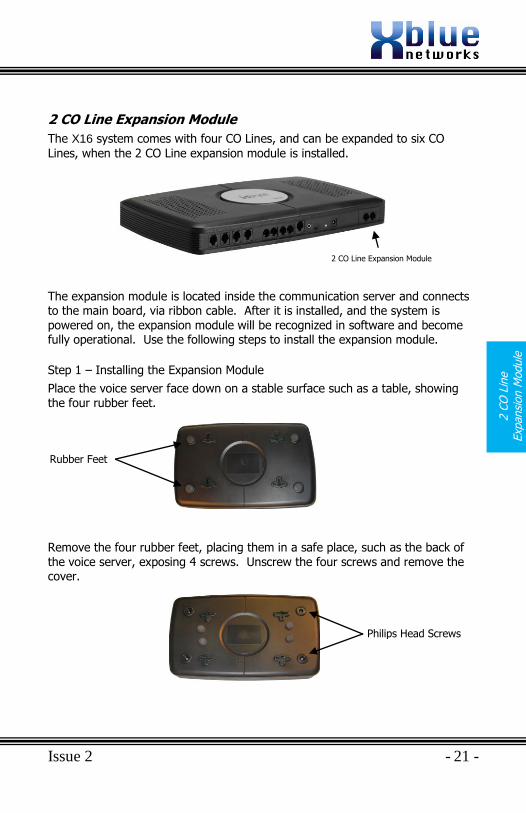
2 CO Line Expansion Module
The X16 system comes with four CO Lines, and can be expanded to six CO
Lines, when the 2 CO Line expansion module is installed.
The expansion module is located inside the communication server and connects to the main board, via ribbon cable. After it is installed, and the system is powered on, the expansion module will be recognized in software and become fully operational. Use the following steps to install the expansion module.
Step 1 – Installing the Expansion Module
Place the voice server face down on a stable surface such as a table, showing the four rubber feet. Remove the four rubber feet, placing them in a safe place, such as the back of the voice server, exposing 4 screws. Unscrew the four screws and remove the cover.
2 CO Line Expansion Module
Philips Head Screws
Rubber Feet
X16 Installation Guide
- 22 - Issue 2
Tele
phone W
all
Mount
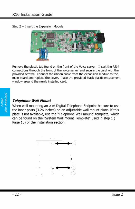
Step 2 – Insert the Expansion Module
Remove the plastic tab found on the front of the Voice server. Insert the RJ14
connections through the front of the voice server and secure the card with the provided screws. Connect the ribbon cable from the expansion module to the main board and replace the cover. Place the provided black plastic encasement window around the newly installed card.
Telephone Wall Mount
When wall mounting an X16 Digital Telephone Endpoint be sure to use
the inner posts (3.26 inches) on an adjustable wall mount plate. If this
plate is not available, use the “Telephone Wall mount” template, which can be found on the “System Wall Mount Template” used in step 1 (
Page 13) of the installation section.
Issue 2 - 23 -
Featu
re D
esc
ription
Feature Description
All Page
At default, one of the flexible buttons is preprogrammed as an “All Page” button. From an Idle telephone, the user may press this button or dial the feature code “Feature +” to page someone through all of the telephone speakers. The paged
party can answer the page, while active, by pressing the “All Page” button from another phone.
Answering Machine Emulation
This feature “Mimics” the call screening feature of an answering machine. Within a specific time after a call is answered by an extension users‟ voice mailbox, that user can monitor/screen callers as they leave a message. The center navigation (Voice mail) button will light which indicates that a caller has been answered by their voice mailbox. The user has the option to monitor the caller or ignore the alert and allow the caller to leave a message. Once the user has selected to monitor the caller, they have the option to leave the caller undisturbed (leaving a message) or to retrieve the caller from the voice mailbox and be connected to the caller for a live conversation. Operation
1) Call Rings an extension, either directly or from the auto attendant. 2) The call is forwarded, if programmed, to the user‟s voice mailbox. 3) The Voicemail button (center navigation) will flash rapidly, which is the
user‟s indication that someone is in their mailbox leaving a message. 4) After the center button is pressed, the calling party will be heard. 5) Lift the handset to retrieve the caller from the voice mailbox. 6) To exit and not retrieve the caller, press the left navigation key
Auto Attendant - Voice Mail (Standard)
The automated attendant can be programmed, in system programming, to answer incoming calls. Callers are then directed to enter, and be transferred to, their desired extension. The system can be programmed to ring only the auto
attendant, only the attendant, or ring all telephones, that are programmed to ring, and then go to the auto attendant for processing.
X16 Installation Guide
- 24 - Issue 2
Featu
re D
escrip
tion
Backlit Blue LCD Display with Power Saver Mode
Each digital telephone endpoint (speakerphone) comes equipped with a backlit display, which can be programmed to go into power saver after it has being idle for 60 seconds. The backlit display is immediately activated whenever an action such as ringing, going off hook or pressing any of the fixed or preprogrammed buttons, is taken.
Call Pick up
There are two types of call pick up, intercom and CO Line. In both cases, the telephone that has the call picked up from must be ringing.
Intercom – When one extension calls another extension, but the called party is not there, the calling party presses the “” key to activate
ringing. If the extension user of the called party hears their extension ringing, they may press the key on any other telephone endpoint and
pick up the actively ringing call. CO Line – Transferred Telephone Company Lines can be picked up by another extension by press the key on their telephone endpoint.
- When the key is pressed the first ringing extension will be picked
up. - When the key is pressed the first transferred CO Line will be
picked up.
Call Timer
When making or receiving a call the backlit display shows the time that the call has been connected in four digit format (00:00).
Caller ID and Call Waiting Caller ID (Type 1 & Type 2)
The telephone company offers two types of caller ID; type 1 and type 2. Type 1 caller ID presents the caller‟s name, number (when available) and the date and time of each call. Type 2 incorporates all of the features of type 1 plus it adds call waiting, caller ID. The system will automatically begin working with caller ID when the user subscribes for the telephone companies Caller ID service, and it will set the system‟s time and date.
Caller ID Enable/Disable
Caller ID can be enabled or disabled at each telephone endpoint (speakerphone). When disabled, the extension will not receive or have access to Caller ID. When Caller ID is disabled, and the button is pressed, a tone will be heard indicating that Caller ID is not accessible.
Issue 2 - 25 -
Featu
re D
esc
ription
CO Line Busy/Idle Status (LED)
Each Preprogrammed CO Line button has an associated dual color Light Emitting Diode (LED), which lights when the line is in use and remains unlit when the line is idle. When the user presses a Line button the LED will illuminate green (I-use) on their telephone and blue (busy) on all telephones. The Line button will light blue (busy) when a device which is connected to a telephone company line, in front of the system, is off hook. Once off hook, only one digital telephone endpoint may access the line by presses the busy line button, all others will receive busy tone.
CO Line Ringing – Per Extension
Each extension may be programmed to ring when a call is received on a specific CO Line. By default, all CO Lines ring on all extensions. This may not be ideal for all installations, so each extension can be programmed, in phone setup, each line to ring or not ring.
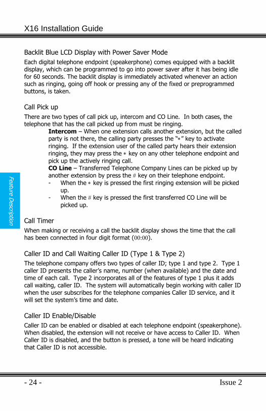
Conference (3-way)
An extension may conference two external parties, or one internal and one external party, together so that they may all converse. (Privacy Release may affect this operation). A conference call cannot be recorded. The system can have two, 3-way calls simultaneously.
To create a conference: 1) Put the first call, must be a CO Line, on Hold 2) Make the second intercom call or CO Line call. After the third party
answers the call, press the “Conf” button. 3) The three parties will be joined together in a conference.
AUTO MUTE
Conf#1+3 00:00
99135992583
X16 Installation Guide
- 26 - Issue 2
Featu
re D
escrip
tion
Conference – Express Conference
Express Conference is a quick and easy way to allow another extension to join in on an existing CO Line call. While speaking with an outside party, the extension user presses the Line button, which is lit green, allowing another party to press the busy (lit blue) line button on their telephone and join in on the existing conversation. If the first extension hangs up, the second extension may continue to speak with the outside party. The second extension‟s line button will turn green allowing the second extension to press the button and have someone else join in on the call.
Operation:
1) An extension (301) makes an outbound or answers an incoming call. 2) The extension user presses the same Line button again. 3) Another extension (302) may now press the busy line button on their
telephone and join in on the existing call. If extension 301 hangs up, the call is “passed” to extension 302. 302 may press the Line button and have another or the same extension, join the call.
Conversation Recording – Voice Mail (Standard)
Extensions come with a preprogrammed button which gives them the ability to record the current conversation. Often referred to as One Touch Record this
feature is extremely helpful for remembering telephone numbers or addresses when a pen and paper are not readily available. The recording is placed in the user‟s personal mailbox so that they may listen at a more convenient time. Note: Call Waiting will not work if an extension is recording a conversation.
Daylight Savings – Automatic (Using CID)
The system uses caller ID to set and resynchronize, the date and time (requires a subscription to the telephone networks‟ caller ID feature). In addition to setting the time and date it is also used to adjusts the time for daylight savings.
Direct CO Line Access
Dial “9” from an idle telephone to access an available CO Line. If all CO Lines are busy, a beep tone is heard and the telephone will not get access to the line.
Issue 2 - 27 -
Featu
re D
esc
ription
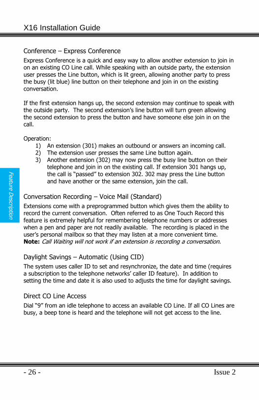
Direct Mailbox Transfer - Voice Mail (Standard)
Callers may be transferred directly into another extension‟s mailbox, so that the caller does not have to wait for the telephone to ring before forwarding. Outside Calls 1) While speaking with the outside caller 2) Press the voice mail button – select button
3) Press the preprogrammed DSS/BLF button or dial the extension number of the intended party.
4) Hang up Inside Calls 1) When calling another extension, if the party does not answer the call, you
may press the “” key to activate ringing.
2) Then press your voice Mail button – Center navigation key 3) Then press the center navigation key again to confirm that you want to
leave a voice mail message – while recording your “record” button will flash.
4) Record message and hang up.
Direct Station Select (DSS) – Busy Lamp Field (BLF)
Each preprogrammed extension (station) button has an associated LED which lights when the Extension is in use and remains unlit when the extension is idle. At default the digital telephone endpoints are preprogrammed with DSS/BLF buttons for extensions 301 through 309.
Distinctive Ringing – Ringer Type
Extension users may select between 6 unique ring tones to differentiate their telephone‟s ring from others in the group.
Do Not Disturb (DND)
When do not disturb is activated all internal and external calls are blocked from ringing that extension. Feature + is used to toggle DND off and on.
AUTO MUTE
Transfer Line#1
To _ Voice Mail
X16 Installation Guide
- 28 - Issue 2
Featu
re D
escrip
tion
Flash
The flash command (Feature + ) is used to invoke features on telephone lines such as call waiting and three-way calling. The Flash command may be programmed on one of the programmable buttons.
Flash Timer
This adjustable timer is used to compensate for telephone network variations.
Forward
Calls can be forwarded to one of three destinations; voice mail, external number
(EXT) or trunk to trunk (TRK2TRK). Calls transferred to an extension that is forwarded, will only forward after the “Waiting Time” has expired. At default the Waiting Time is set to 10 seconds. Use the “Phone Programming” area to program this parameter. Voice mail – At default all extensions are forwarded to voice mail, and the center navigation button will be illuminated (lit solid); no other visual indication will be given. After the expiration of the Waiting Time, the call will be diverted (redirected) to the extension‟s Outgoing Message (OGM). TRK2TRK – When an extension is forwarded to an external number the system will send a command to the telephone network line, known as a “Flash”, which begins the transfer. The telephone system will then dial the preprogrammed digits, pause until the call is established, and then hang up, releasing the call from the system. TRK2TRK FWD will appear in the display, use the right navigation button to clear this from the display. Note: This feature may require a special service from the telephone company central office called, “Three-way calling with call disconnect”. Please consult with your telephone company for information regarding this feature. This type of forwarding may result in a usage and toll charge for each forwarded call. Any and all toll charges are the sole responsibility of the user of the installed equipment; XBLUE offers no warranty or will assume any responsibility for any toll charges.
External – External Call forwarding uses two telephone system lines.
1) This feature occupies two CO Lines. Therefore, if a second CO Line is not available, the call will not forward. Also, a slight volume decrease is normal.
Issue 2 - 29 -
Featu
re D
esc
ription
2) If an ancillary device (single line before the system) is on a CO Line, and the system does not detect that line as being busy, the system will forward the call, and dial over the call.
3) This feature is considered disabled if no number is entered in the “FWD Phone Number” field.
4) At default the “External” transfer will release after 3 minutes. Use the following codes to extend the length of the call
a. – Extends the call by 1 Minute
b. – Extends the call by 2 Minutes c. – Extends the call by 3 Minutes
d. – Extends the call by 4 Minutes
e. – Extends the call by 5 Minutes
f. – Extends the call by 6 Minutes
g. – Extends the call by 7 Minutes
h. – Extends the call by 8 Minutes
i. – Extends the call by 9 Minutes
j. – Extends the call by 20 Minutes
k. – Extends the call by 30 Minutes l. – Disconnects both lines immediately
Note: This type of forwarding may result in a per call usage and toll charge for each forwarded call. Any and all toll charges are the sole responsibility of the user of the installed equipment; XBLUE offers no warranty or will assume any responsibility for any toll charges.
Hands-Free Calling
Calls between extensions are answered hands-free. This allows extension users to answer and converse without pressing the speaker button or lifting the handset. If “Auto Mute” is enabled the called party will be able to hear the calling party, but they will not be able to converse without pressing the mute button or going off hook on the handset. There will be one, 1 second tone when an extension calls another extension. At default, Auto Mute is disabled (off).
Handset/Headset Volume Control
The volume of the handset and headset can be adjusted to compensate for hearing levels. Press the volume + to increase or the volume- to decrease the
volume of the active status of the endpoint. For example, while speaking on the handset, the volume keys will adjust the handset volume.
X16 Installation Guide
- 30 - Issue 2
Featu
re D
escrip
tion
Headset Activation
Each digital telephone endpoint comes with a 1/8 inch (2.55 mm) standard “cellular” style telephone headset jack, which can be activated by dialing the feature code Feature + . This feature code can be programmed on a button, so
that headset can be enabled and disabled as needed. In addition, a headset must be plugged in to enable or disable headset mode. Note: The voice quality and performance of headsets may vary.
Hold
Extension users may place Telephone Company central office line calls on hold allowing them to be picked up at other extensions.
Hot Dial Pad
Hot dial pad allows extension users to dial numbers without lifting the handset or pressing the speaker button.
Intercom Calling
Each extension is assigned a unique three digit code (number) ranging from 301 to 399. The number used at the time of registration and becomes that extension‟s intercom number. Dial the three digit code to intercom another extension. DSS/BLF buttons allows for one touch intercom calling.
Intercom Paging
Intercom paging is similar to intercom calling, but when the call is connected, the called party‟s mute button is active. This allows the called party to have private conversations without being overheard.
Line Status Detection (Line in Use)
From Idle to Busy – The system will detect if another device is using one of the CO Lines and will automatically identify the line as busy. From Busy to Idle – The system will detect when the line is no longer busy, and automatically identify the line as idle. Not Connected – If a CO line is not connected to the system, it will be automatically disabled, and no one will be able to connect to the line. A beep tone is heard if a disabled CO Line is pressed.
Issue 2 - 31 -
Featu
re D
esc
ription
Non-system phone picking up the call – When the call is picked up by a non-system phone, the system will, after 2 seconds, light the line button and show that the line as busy. However, one digital telephone may join in on the call by pressing the lit CO Line. If a second digital telephone tries to join the conversation both digital telephones will be disconnected but the non-system telephone will retain the call. When the call is disconnected, the line will return to idle.
Memo Recording - Voice Mail (Standard)
The voice mail is equipped to record a memo, or a meeting in an office, by pressing the preprogrammed Record button. When finished, press the speaker button or replace the handset to hang up. The memo is then placed into the user‟s mailbox. In addition, a remote user may also record a memo after they are in their mailbox. A memo should not exceed 35 minutes in length.
Message Waiting (Telephone Company-FSK)
The Telephone Company‟s voice mail system alerts the user via a visual (light) and/or an audible stutter dial tone when there is a new voice mail message. If the system receives this indication, it will update the LCD display and flash indicating which CO Lines have messages. For example, If CO Lines 1, 3 and 5 have messages, the LCD will blink showing CO MSGW: 1 3 5.
Multilingual Display per Extension
Each extension may select between three different languages English, French and Spanish to be used in their display. The display will update to the proper language in a real-time fashion. Therefore if the extension user select French, all of their interactions with the display will be in French.
Music on Hold Input
The system comes standard with one music on hold input which can be connected to an external message on hold or music on hold source. All Calls placed on hold or being transferred will hear this message/music rather than silence.
AUTO MUTE
09:05 A 02/24 MON
CO MSGW: 1 3 5
X16 Installation Guide
- 32 - Issue 2
Featu
re D
escrip
tion
Mute with LED indication
When the Mute button is pressed, the LED illuminates, and mute becomes active. This means that the transmit function for that extension is suspended; allowing the user to converse privately.
Muted Ring (Ring Alert)
Extensions that are programmed to ring, but are currently on a telephone line or extension call, will receive a 1-second beep every 5 seconds until the line is forwarded or answered by another extension. This feature can be disabled, so no beep is heard by setting the “2nd Call Beep”, found in “Phone Setup” to “No”.
Navigation Keys
Each digital telephone endpoint has a set of five navigation keys which are used to scroll through and activate features.
New Message Playback - Voice Mail (Standard)
Voice mail messages are played one after the other until all messages are heard. Each message is automatically saved. To delete a voice mail message press the delete key while the message is playing. Remote Access allows extension users to select between playing all new messages (dial 2) or all messages (dial 2#). All messages are automatically saved after playing.
Paging
An extension user may dial Feature + or press the preprogrammed feature
button to active one-way paging to make an announcement to all extension users. If the extension answers an inbound call, and dials the code or presses the “All Page” button, the CO Line will automatically be placed on hold and activate the paging procedure.
Meet Me Answer (Paging)
After a one-way page is activated, the “Meet Me” answer code Feature + can
be dialed or the preprogrammed “All Page button” can pressed to have a private conversation with the extension doing the Paging.
Issue 2 - 33 -
Featu
re D
esc
ription
Pause
The system has a programmable pause, which can be used in speed bins, redial numbers, etc. to insert a short delay before more numbers are dialed. This can be very helpful when using special features such as “Call Waiting Cancel”. Press Feature + - to enter a pause into a dial string. A Pause will be displayed
as a “P”.
Personal Mailbox - Voice Mail (Standard)
Extension users have a voice mailbox that can be programmed to play a personal outgoing message (OGM) which will be heard by callers when they are redirected to the called party‟s mailbox.
Phone Book Dialing
Each extension has a personal phone book, which stores up to 50 entries with name and number and when accessed the list is presented in alphabetical order. The maximum number of digits that any one entry will store is 24 digits.
Privacy (Privacy Release)
All calls in the system are considered private, and no one can “Barge in” unless the express conference (see Express Conference Page 25) feature is used.
Programmable Buttons (12)
All digital telephone endpoints have 12 programmable buttons which can be customized by each user to accommodate the way they use their telephone. (See Programming Feature Buttons)
Programmable Pause (Speed Dial Bins)
The system has a programmable pause, which can be used in a speed bin, to insert a short delay before more numbers are dialed. (See Pause)
Redial (Last 6 Number Redial)
The Redial button allows the user to press one button and select from the last six telephone numbers dialed. Using the up or down navigation keys, select which of the six numbers to redial, and then press the select button. In addition, any one of the six numbers can be copied into the phone book.
X16 Installation Guide
- 34 - Issue 2
Featu
re D
escrip
tion
Operation: 1) Press the redial button to display the list 2) Press the up or down navigation key to scroll through the list. 3) When the desired number is in the display, press the select button. 4) Press the select button again to dial the displayed number or press the
up or down navigation key to select between coping the displayed telephone number to the phone book to cancel the redial function.
Ring Alert (Muted Ringing)
Extensions that are programmed to ring, but are currently on a telephone line or extension call, will receive a 1-second beep every 5 seconds until the line is forwarded or answered by another extension. This feature can be disabled, so no beep is heard by setting the “2nd Call Beep”, found in “Phone Setup” to “No”. (See Muted Ring)
Ringing (Audible and Visual)
When an extension is ringing, there will be an audible sound, which can be adjusted from very low to very loud and a visual indication, flashing LED, to indicate that the extension is ringing.
Ringer Volume Control
Using the digital telephone endpoint‟s volume up and down keys, an extension user may adjust the ringing volume of their telephone, while the call is ringing.
Room Monitor
Each telephone endpoint can be used as a “Room Monitor” device. The called extension must have the “Auto Mute” feature disabled before monitoring can begin.
Setting Time and Date (Automatic)
The system‟s time and date is programmed in System Setup. In addition, if Caller ID is received by the system it will resynchronize the time each day and automatically update the clock for daylight savings.
Set Relocation
Extension parameters such as voicemail will remain for up to 120 seconds when an extension is unplugged or being relocated. To relocate an extension simply unplug it and plug it into the new extension port. Note: An “Endpoint Device” may be needed when relocating an extension.
Issue 2 - 35 -
Featu
re D
esc
ription
Speakerphone (Digital Telephone Endpoint) with LED
Each digital telephone endpoint is equipped as a speakerphone. When the speakerphone is active, the LED will be illuminated.
Speed Dial Bins
The station has 12 speed dial bins; each can take up to 24 digits to be dialed.
Time in Display
All digital telephone endpoints have a backlit Liquid Crystal Display (LCD) display which when idle, displays the current date and time, extension name and number, even when it is in power saver mode.
Tone/Pulse
The system can accommodate either DTMF Tone or Dial Pulse dialing.
Transfer
Telephone Company (CO) Line Calls answered at one extension can be transferred to another extension in the system. To transfer a call:
1) While on a telephone line 2) Press Transfer button 3) Press the preprogrammed button or dial the extension number where
you would like to transfer the call. 4) The call will automatically be transferred, so simply hang up.
Transfer – Direct to Voice Mail
1) While on a telephone line 2) Press the Voice mail button 3) Press the preprogrammed DSS/BLF button or dial the extension number
where the caller would like to leave or retrieve a message.
Volume Adjustments
Ringing Volume While your telephone is idle or ringing, use the volume up key to increase or the volume down key to decrease the ringing volume. Speakerphone Intercom Volume While using your speakerphone, use the volume up key to increase or the volume down key to decrease the speakerphone volume.
X16 Installation Guide
- 36 - Issue 2
Featu
re D
escrip
tion
Speakerphone Network Volume While using your speakerphone, use the volume up key to increase or the volume down key to decrease the speakerphone volume. Handset Intercom Volume While speaking to another extension using your handset, use the volume up key to increase or the volume down key to decrease the handset volume. Handset Network Volume While speaking on a telephone company line, using your handset, use the volume up key to increase or the volume down key to decrease the handset
volume. Forced Ringing Intercom Volume Calls between extensions are answered hands free and will not forward to
voicemail. To forward intercom calls to voicemail, press the “” key, which will
force the extension to start ringing.
Voice Mail (Standard)
Each extension has a personal voice mailbox. The extension user‟s “Outgoing Message” will be heard when callers are redirected to their personal mailbox.
Waiting Time
When a call is transferred from the auto attendant the call waiting timer begins, at the expiration of the timer the call will be forwarded to the programmed forward destination. When the timer is set to 00, the call will immediately be transferred to the mailbox without ringing the extension first.
Issue 2 - 37 -
Pro
gra
mm
ing
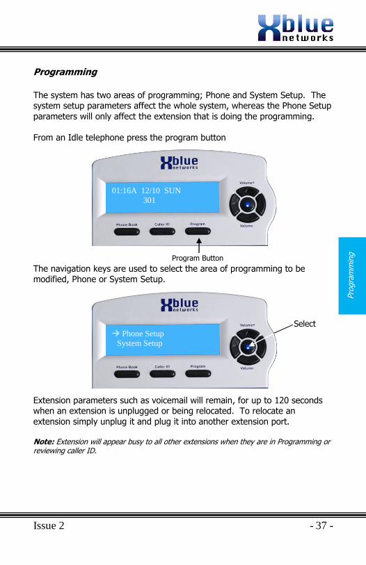
Programming
The system has two areas of programming; Phone and System Setup. The system setup parameters affect the whole system, whereas the Phone Setup
parameters will only affect the extension that is doing the programming.
From an Idle telephone press the program button
The navigation keys are used to select the area of programming to be modified, Phone or System Setup.
Extension parameters such as voicemail will remain, for up to 120 seconds when an extension is unplugged or being relocated. To relocate an
extension simply unplug it and plug it into another extension port.
Note: Extension will appear busy to all other extensions when they are in Programming or reviewing caller ID.
Program Button
01:16A 12/10 SUN
301
Phone Setup
System Setup
Select
X16 Installation Guide
- 38 - Issue 2
Navig
atio
n K
eys
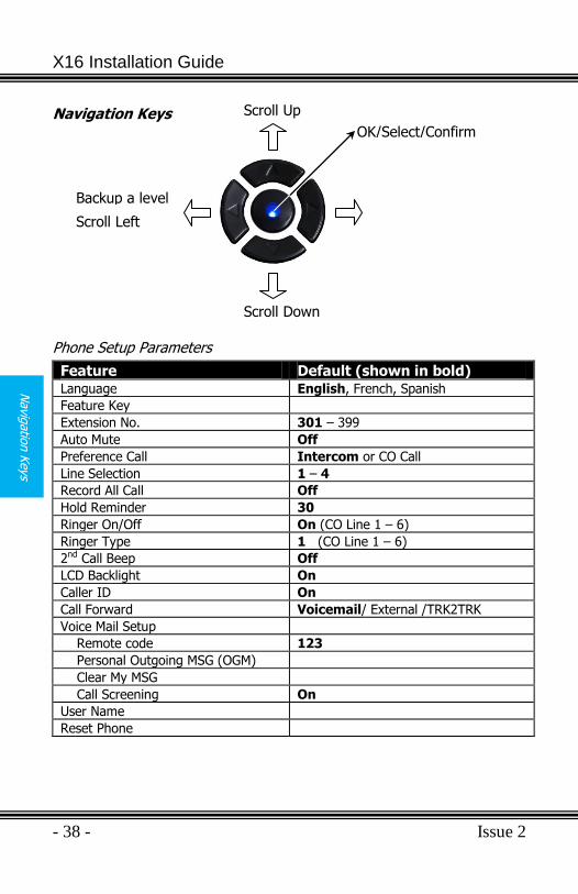
Navigation Keys
Phone Setup Parameters
Feature Default (shown in bold) Language English, French, Spanish
Feature Key
Extension No. 301 – 399
Auto Mute Off
Preference Call Intercom or CO Call
Line Selection 1 – 4
Record All Call Off
Hold Reminder 30
Ringer On/Off On (CO Line 1 – 6)
Ringer Type 1 (CO Line 1 – 6)
2nd Call Beep Off
LCD Backlight On
Caller ID On
Call Forward Voicemail/ External /TRK2TRK
Voice Mail Setup
Remote code 123
Personal Outgoing MSG (OGM)
Clear My MSG
Call Screening On
User Name
Reset Phone
OK/Select/Confirm
Scroll Up
Scroll Down
Backup a level
Scroll Left
Issue 2 - 39 -
Phone S
etu
p
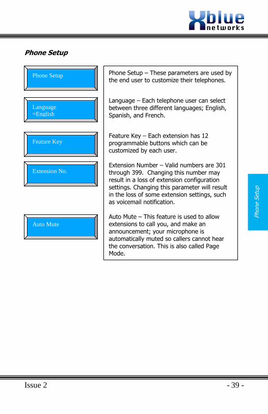
Phone Setup
Phone Setup – These parameters are used by the end user to customize their telephones.
Language – Each telephone user can select between three different languages; English, Spanish, and French.
Feature Key – Each extension has 12 programmable buttons which can be customized by each user. Extension Number – Valid numbers are 301 through 399. Changing this number may result in a loss of extension configuration settings. Changing this parameter will result in the loss of some extension settings, such as voicemail notification. Auto Mute – This feature is used to allow extensions to call you, and make an announcement; your microphone is automatically muted so callers cannot hear the conversation. This is also called Page Mode.
AUTO MUTE
Phone Setup
AUTO MUTE
Language
=English
AUTO MUTE
Feature Key
AUTO MUTE
Extension No.
AUTO MUTE
Auto Mute
X16 Installation Guide
- 40 - Issue 2
Phone S
etu
p
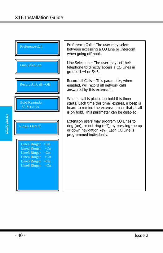
Preference Call – The user may select between accessing a CO Line or Intercom when going off hook. Line Selection – The user may set their telephone to directly access a CO Lines in groups 1~4 or 5~6. Record all Calls – This parameter, when
enabled, will record all network calls answered by this extension. When a call is placed on hold this timer starts. Each time this timer expires, a beep is heard to remind the extension user that a call is on hold. This parameter can be disabled. Extension users may program CO Lines to ring (on), or not ring (off), by pressing the up or down navigation key. Each CO Line is programmed individually.
AUTO MUTE
Preference Call
AUTO MUTE
Line Selection
AUTO MUTE
Record All Call =Off
AUTO MUTE
Hold Reminder
=30 Seconds
AUTO MUTE
Ringer On/Off
Line1 Ringer =On
Line2 Ringer =On
Line3 Ringer =On
Line4 Ringer =On
Line5 Ringer =On
Line6 Ringer =On
Issue 2 - 41 -
Phone S
etu
p
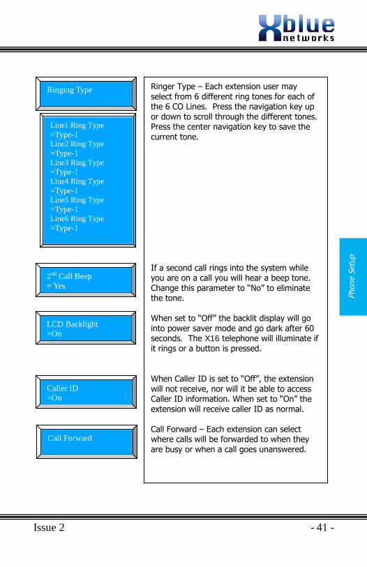
Ringer Type – Each extension user may select from 6 different ring tones for each of the 6 CO Lines. Press the navigation key up or down to scroll through the different tones. Press the center navigation key to save the current tone.
If a second call rings into the system while you are on a call you will hear a beep tone. Change this parameter to “No” to eliminate the tone.
When set to “Off” the backlit display will go into power saver mode and go dark after 60 seconds. The X16 telephone will illuminate if it rings or a button is pressed. When Caller ID is set to “Off”, the extension will not receive, nor will it be able to access Caller ID information. When set to “On” the extension will receive caller ID as normal.
Call Forward – Each extension can select where calls will be forwarded to when they are busy or when a call goes unanswered.
Line1 Ring Type
=Type-1 Line2 Ring Type
=Type-1 Line3 Ring Type =Type-1 Line4 Ring Type
=Type-1 Line5 Ring Type
=Type-1 Line6 Ring Type
=Type-1
AUTO MUTE
Ringing Type
AUTO MUTE
Call Forward
AUTO MUTE
2nd Call Beep
= Yes
AUTO MUTE
LCD Backlight
=On
AUTO MUTE
Caller ID
=On
X16 Installation Guide
- 42 - Issue 2
Phone S
etu
p
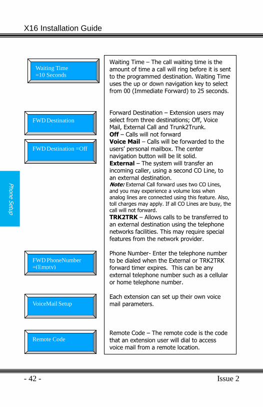
Waiting Time – The call waiting time is the amount of time a call will ring before it is sent to the programmed destination. Waiting Time uses the up or down navigation key to select from 00 (Immediate Forward) to 25 seconds. Forward Destination – Extension users may select from three destinations; Off, Voice Mail, External Call and Trunk2Trunk.
Off – Calls will not forward Voice Mail – Calls will be forwarded to the users‟ personal mailbox. The center navigation button will be lit solid. External – The system will transfer an incoming caller, using a second CO Line, to an external destination. Note: External Call forward uses two CO Lines, and you may experience a volume loss when analog lines are connected using this feature. Also, toll charges may apply. If all CO Lines are busy, the call will not forward. TRK2TRK – Allows calls to be transferred to an external destination using the telephone networks facilities. This may require special features from the network provider. Phone Number- Enter the telephone number to be dialed when the External or TRK2TRK forward timer expires. This can be any external telephone number such as a cellular or home telephone number. Each extension can set up their own voice mail parameters. Remote Code – The remote code is the code that an extension user will dial to access voice mail from a remote location.
AUTO MUTE
Waiting Time
=10 Seconds
AUTO MUTE
FWD Destination
AUTO MUTE
FWD Destination =Off
AUTO MUTE
FWD PhoneNumber
=(Empty)
AUTO MUTE
VoiceMail Setup
AUTO MUTE
Remote Code
Issue 2 - 43 -
Phone S
etu
p
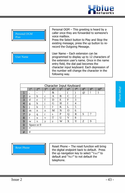
Character Input Keyboard
1st 2nd 3rd 4th 5th 6th 7th 8th 9th 10th
1 , - „ & . ( ) @ ! 1
2 a b c A B C 2
3 d e f D E F 3
4 g h i G H I 4
5 j k l J K L 5
6 m n o M N O 6
7 p q r s P Q R S 7
8 t u v T U V 8
9 w x y z W X Y Z 9
0 Space or 0
* *
# #
Personal OGM – This greeting is heard by a caller once they are forwarded to someone‟s voice mailbox. Press the Select button to Play and Stop the existing message, press the up button to re-record the Outgoing Message. User Name – Each extension can be programmed to display up to 12 characters of the extension user‟s name. Once in the name entry field, the dial pad becomes the character input keyboard. Each depression of the number will change the character in the following way.
Reset Phone – The reset function will bring the digital endpoint back to default. Press the up navigation key to select “Yes?” to default and “No?” to not default the
telephone.
AUTO MUTE
Personal OGM
Play
AUTO MUTE
User Name
AUTO MUTE
Reset Phone
X16 Installation Guide
- 44 - Issue 2
Phone S
etu
p
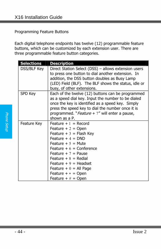
Programming Feature Buttons
Each digital telephone endpoints has twelve (12) programmable feature buttons, which can be customized by each extension user. There are
three programmable feature button categories.
Selections Description
DSS/BLF Key Direct Station Select (DSS) – allows extension users
to press one button to dial another extension. In addition, the DSS button doubles as Busy Lamp
(LED) Field (BLF). The BLF shows the status, idle or busy, of other extensions.
SPD Key Each of the twelve (12) buttons can be programmed
as a speed dial key. Input the number to be dialed once the key is identified as a speed key. Simply
press the speed key to dial the number once it is
programmed. “Feature + ” will enter a pause,
shown as a P.
Feature Key Feature + = Record
Feature + = Open
Feature + = Flash Key
Feature + = DND
Feature + = Mute
Feature + = Conference
Feature + = Pause
Feature + = Redial
Feature + = Headset
Feature + = All Page
Feature + = Open
Feature + = Open
Issue 2 - 45 -
Phone S
etu
p
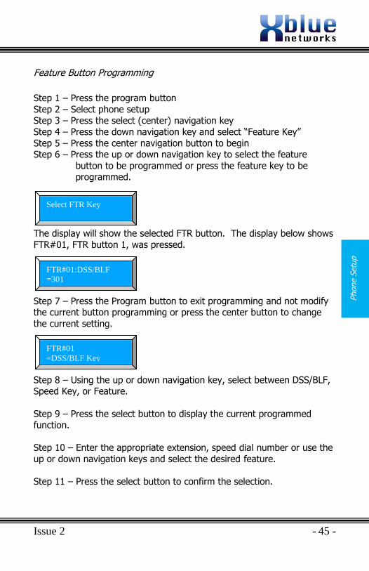
Feature Button Programming
Step 1 – Press the program button
Step 2 – Select phone setup Step 3 – Press the select (center) navigation key
Step 4 – Press the down navigation key and select “Feature Key”
Step 5 – Press the center navigation button to begin Step 6 – Press the up or down navigation key to select the feature
button to be programmed or press the feature key to be programmed.
The display will show the selected FTR button. The display below shows
FTR#01, FTR button 1, was pressed.
Step 7 – Press the Program button to exit programming and not modify the current button programming or press the center button to change
the current setting.
Step 8 – Using the up or down navigation key, select between DSS/BLF, Speed Key, or Feature.
Step 9 – Press the select button to display the current programmed function.
Step 10 – Enter the appropriate extension, speed dial number or use the
up or down navigation keys and select the desired feature.
Step 11 – Press the select button to confirm the selection.
AUTO MUTE
Select FTR Key
AUTO MUTE
FTR#01:DSS/BLF
=301
AUTO MUTE
FTR#01
=DSS/BLF Key

X16 Installation Guide
- 46 - Issue 2
Phone S
etu
p
Notes:
Issue 2 - 47 -
Sys
tem
Setu
p
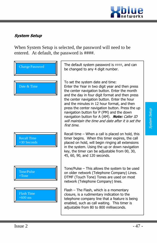
System Setup
When System Setup is selected, the password will need to be
entered. At default, the password is ####.
The default system password is , and can
be changed to any 4 digit number.
To set the system date and time: Enter the Year in two digit year and then press the center navigation button. Enter the month and the day in four digit format and then press the center navigation button. Enter the hour and the minutes in 12 hour format, and then press the center navigation button. Press the up navigation button for P (PM) and the down navigation button for A (AM). Note: Caller ID will maintain the time and date after it is set the first time.
Recall time – When a call is placed on hold, this timer begins. When this timer expires, the call placed on hold, will begin ringing all extensions in the system. Using the up or down navigation key, the timer can be adjustable from 00, 30, 45, 60, 90, and 120 seconds. Tone/Pulse – This allows the system to be used on older network (Telephone Company) Lines. DTMF (Touch Tone) Tones are used on most network (Telephone Company) lines.
Flash – The Flash, which is a momentary closure, is a rudimentary indication to the telephone company line that a feature is being enabled, such as call waiting. This timer is adjustable from 80 to 800 milliseconds.
AUTO MUTE
Change Password
AUTO MUTE
Date & Time
AUTO MUTE
Recall Time
=30 Seconds
AUTO MUTE
Tone/Pulse
=Tone
AUTO MUTE
Flash Time
=600 ms
X16 Installation Guide
- 48 - Issue 2
Syste
m S
etu
p
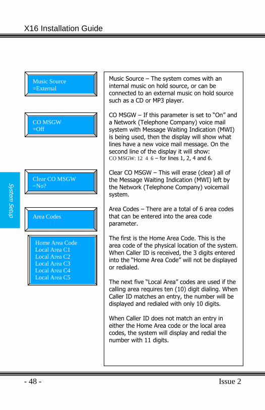
Music Source – The system comes with an internal music on hold source, or can be connected to an external music on hold source such as a CD or MP3 player. CO MSGW – If this parameter is set to “On” and a Network (Telephone Company) voice mail system with Message Waiting Indication (MWI)
is being used, then the display will show what lines have a new voice mail message. On the second line of the display it will show: CO MSGW: 12 4 6 – for lines 1, 2, 4 and 6.
Clear CO MSGW – This will erase (clear) all of the Message Waiting Indication (MWI) left by the Network (Telephone Company) voicemail system. Area Codes – There are a total of 6 area codes that can be entered into the area code parameter. The first is the Home Area Code. This is the area code of the physical location of the system. When Caller ID is received, the 3 digits entered into the “Home Area Code” will not be displayed or redialed. The next five “Local Area” codes are used if the calling area requires ten (10) digit dialing. When Caller ID matches an entry, the number will be displayed and redialed with only 10 digits.
When Caller ID does not match an entry in either the Home Area code or the local area codes, the system will display and redial the number with 11 digits.
AUTO MUTE
Music Source
=External
AUTO MUTE
CO MSGW
=Off
AUTO MUTE
Clear CO MSGW
=No?
AUTO MUTE
Area Codes
Home Area Code
Local Area C1
Local Area C2
Local Area C3
Local Area C4
Local Area C5
Issue 2 - 49 -
Sys
tem
Setu
p
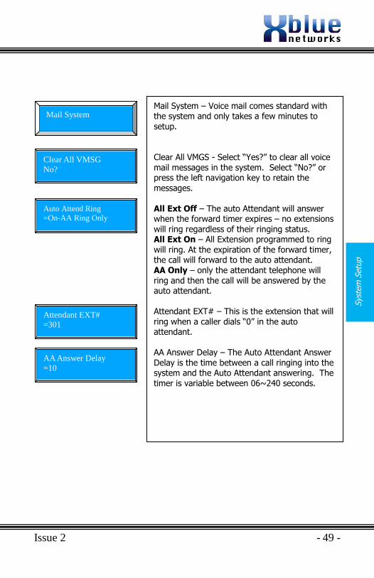
Mail System – Voice mail comes standard with the system and only takes a few minutes to setup. Clear All VMGS - Select “Yes?” to clear all voice mail messages in the system. Select “No?” or press the left navigation key to retain the
messages. All Ext Off – The auto Attendant will answer when the forward timer expires – no extensions will ring regardless of their ringing status. All Ext On – All Extension programmed to ring will ring. At the expiration of the forward timer, the call will forward to the auto attendant. AA Only – only the attendant telephone will ring and then the call will be answered by the auto attendant. Attendant EXT# – This is the extension that will ring when a caller dials “0” in the auto attendant. AA Answer Delay – The Auto Attendant Answer Delay is the time between a call ringing into the system and the Auto Attendant answering. The timer is variable between 06~240 seconds.
AUTO MUTE
Mail System
Clear All VMSG
No?
Auto Attend Ring
=On-AA Ring Only
Attendant EXT#
=301
AA Answer Delay
=10
X16 Installation Guide
- 50 - Issue 2
Syste
m S
etu
p
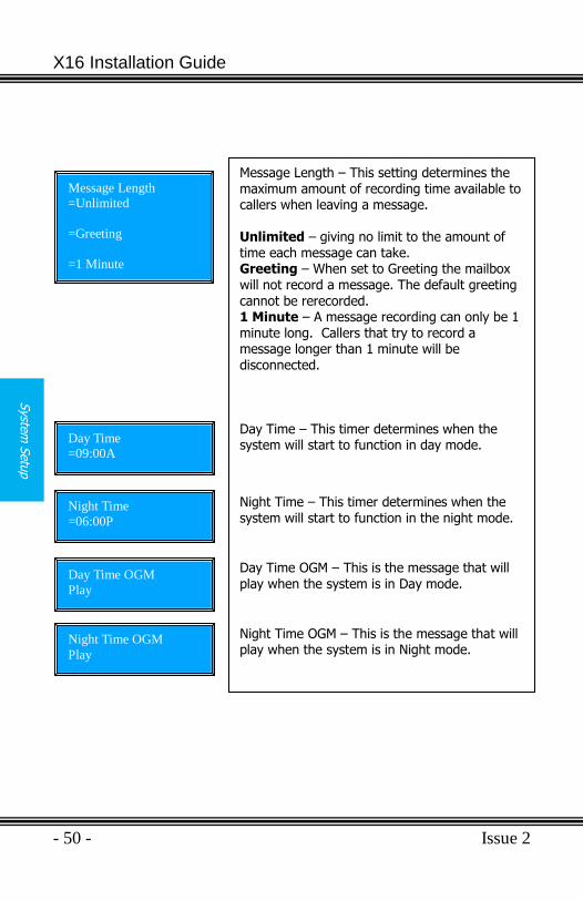
Message Length – This setting determines the maximum amount of recording time available to callers when leaving a message. Unlimited – giving no limit to the amount of time each message can take. Greeting – When set to Greeting the mailbox will not record a message. The default greeting
cannot be rerecorded. 1 Minute – A message recording can only be 1 minute long. Callers that try to record a message longer than 1 minute will be disconnected. Day Time – This timer determines when the system will start to function in day mode.
Night Time – This timer determines when the system will start to function in the night mode.
Day Time OGM – This is the message that will play when the system is in Day mode.
Night Time OGM – This is the message that will play when the system is in Night mode.
Message Length
=Unlimited
=Greeting
=1 Minute
Day Time
=09:00A
Night Time
=06:00P
Day Time OGM
Play
Night Time OGM
Play
Issue 2 - 51 -
Sys
tem
Setu
p
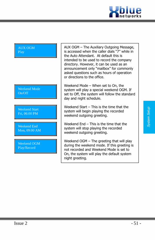
AUX OGM – The Auxiliary Outgoing Message, is accessed when the caller dials “7” while in the Auto Attendant. At default this is intended to be used to record the company directory. However, it can be used as an announcement only “mailbox” for commonly asked questions such as hours of operation
or directions to the office. Weekend Mode – When set to On, the system will play a special weekend OGM. If set to Off, the system will follow the standard day and night schedule. Weekend Start – This is the time that the system will begin playing the recorded weekend outgoing greeting. Weekend End – This is the time that the system will stop playing the recorded
weekend outgoing greeting. Weekend OGM – The greeting that will play during the weekend mode. If this greeting is not recorded and Weekend Mode is set to On, the system will play the default system night greeting.
AUX OGM
Play
Weekend Mode
On/Off
Weekend Start
Fri, 06:00 PM
Weekend End
Mon, 09:00 AM
Weekend OGM
Play/Record
X16 Installation Guide
- 52 - Issue 2
Syste
m S
etu
p
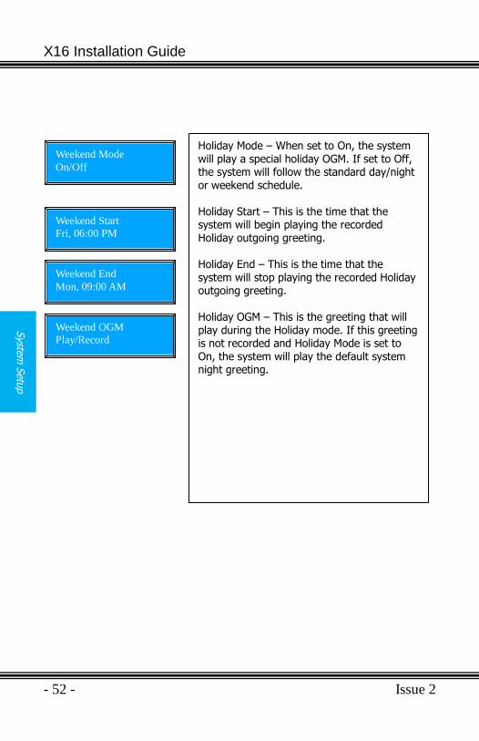
Holiday Mode – When set to On, the system will play a special holiday OGM. If set to Off, the system will follow the standard day/night or weekend schedule. Holiday Start – This is the time that the system will begin playing the recorded
Holiday outgoing greeting. Holiday End – This is the time that the system will stop playing the recorded Holiday outgoing greeting. Holiday OGM – This is the greeting that will play during the Holiday mode. If this greeting is not recorded and Holiday Mode is set to On, the system will play the default system night greeting.
Weekend Mode
On/Off
Weekend Start
Fri, 06:00 PM
Weekend End
Mon, 09:00 AM
Weekend OGM
Play/Record
Issue 2 - 53 -
Pro
gra
mm
ing G
uid
e
Programming Guide
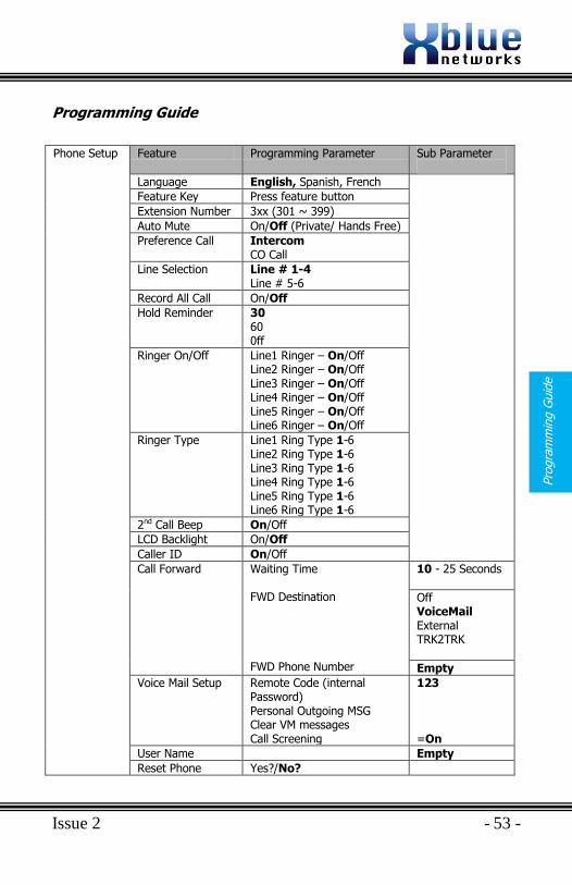
Phone Setup Feature Programming Parameter Sub Parameter
Language English, Spanish, French
Feature Key Press feature button
Extension Number 3xx (301 ~ 399)
Auto Mute On/Off (Private/ Hands Free)
Preference Call Intercom CO Call
Line Selection Line # 1-4 Line # 5-6
Record All Call On/Off
Hold Reminder 30 60 0ff
Ringer On/Off Line1 Ringer – On/Off Line2 Ringer – On/Off Line3 Ringer – On/Off Line4 Ringer – On/Off Line5 Ringer – On/Off Line6 Ringer – On/Off
Ringer Type Line1 Ring Type 1-6 Line2 Ring Type 1-6 Line3 Ring Type 1-6 Line4 Ring Type 1-6 Line5 Ring Type 1-6 Line6 Ring Type 1-6
2nd Call Beep On/Off
LCD Backlight On/Off
Caller ID On/Off
Call Forward Waiting Time FWD Destination FWD Phone Number
10 - 25 Seconds
Off VoiceMail External TRK2TRK
Empty
Voice Mail Setup Remote Code (internal Password) Personal Outgoing MSG Clear VM messages Call Screening
123 =On
User Name Empty
Reset Phone Yes?/No?
X16 Installation Guide
- 54 - Issue 2
Pro
gram
min
g G
uid
e
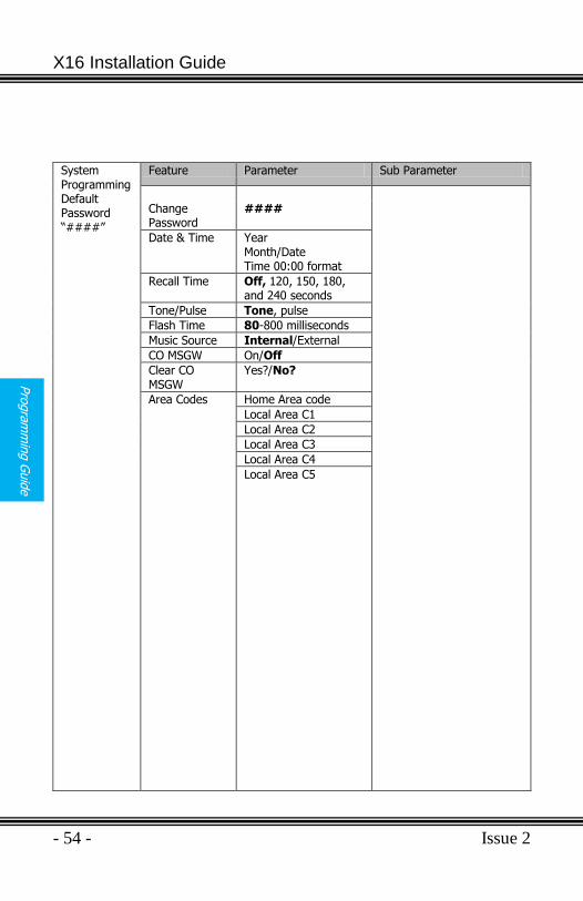
System Programming Default Password “####”
Feature Parameter Sub Parameter
Change Password
####
Date & Time Year Month/Date Time 00:00 format
Recall Time Off, 120, 150, 180, and 240 seconds
Tone/Pulse Tone, pulse
Flash Time 80-800 milliseconds
Music Source Internal/External
CO MSGW On/Off
Clear CO MSGW
Yes?/No?
Area Codes
Home Area code
Local Area C1
Local Area C2
Local Area C3
Local Area C4
Local Area C5
Issue 2 - 55 -
Pro
gra
mm
ing G
uid
e
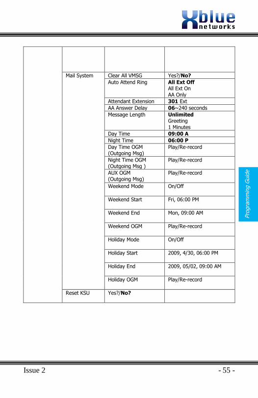
Mail System Clear All VMSG Yes?/No?
Auto Attend Ring All Ext Off All Ext On AA Only
Attendant Extension 301 Ext
AA Answer Delay 06~240 seconds
Message Length Unlimited Greeting 1 Minutes
Day Time 09:00 A
Night Time 06:00 P
Day Time OGM (Outgoing Msg)
Play/Re-record
Night Time OGM (Outgoing Msg )
Play/Re-record
AUX OGM (Outgoing Msg)
Play/Re-record
Weekend Mode On/Off
Weekend Start Fri, 06:00 PM
Weekend End Mon, 09:00 AM
Weekend OGM Play/Re-record
Holiday Mode On/Off
Holiday Start 2009, 4/30, 06:00 PM
Holiday End 2009, 05/02, 09:00 AM
Holiday OGM Play/Re-record
Reset KSU Yes?/No?
X16 Installation Guide
- 56 - Issue 2
Rin
gin
g S
cenario
s
Ringing Scenarios
Auto Attendant
The Auto Attendant can be set to All EXT Off, All EXT On, or AA Only
All Extensions Ringing Off
When set to All EXT Off, none of the telephones will ring, even if they are programmed to ring, and when the AA Answer Delay timer expires, the call will be forwarded to the Auto Attendant.
All Extensions Ringing On
When set to All EXT on, all of the telephones that are programmed to ring will ring. If the call goes unanswered, the call will be forwarded to the Auto Attendant when the AA Answer Delay timer expires.
AA Only
AA Only, only the extension defined as the attendant (301 at default) will ring until the AA Answer Delay Timer expires. If the timer is set to 10 seconds, for example, the attendant extension will ring up to two times before the auto attendant answers.
Ringing
Each extension may be programmed to ring or not ring, depending on the telephones programming. However, the Auto Attendant must be set to “All EXT On” to allow extensions to ring before the auto attendant answers the call. The telephones will ring unit the AA Answer Delay Timer expires. The AA Answer Delay Timer can be set from 06 seconds to 240 seconds.
Common Ringing
Auto Attendant Ring – Set to “All EXT Ring On” to allow all programmed telephones to ring before the call is forwarded to Auto Attendant. Auto Attendant Ring – Set to “All EXT Ring Off” to stop any telephone from ringing, thus allowing the Auto Attendant to answer when the AA Answer Delay timer expires. AA Only – Only the Attendant will ring, and then the call will be forwarded to the Auto Attendant.
Issue 2 - 57 -
Funct
ions
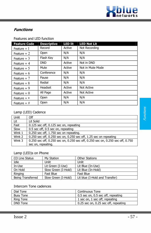
Functions
Features and LED function
Feature Code Descriptive LED lit LED Not Lit
Feature + Record Active Not Recording
Feature + Open N/A N/A
Feature + Flash Key N/A N/A
Feature + DND Active Not in DND
Feature + Mute Active Not in Mute Mode
Feature + Conference N/A N/A
Feature + Pause N/A N/A
Feature + Redial N/A N/A
Feature + Headset Active Not Active
Feature + All Page Active Not Active
Feature + Open N/A N/A
Feature + Open N/A N/A
Lamp (LED) Cadence
Unlit Off
Lit Lit Solid
Fast 0.125 sec off, 0.125 sec on, repeating
Slow 0.5 sec off, 0.5 sec on, repeating
Wink 1 0.250 sec off, 1.750 sec on repeating.
Wink 2 0.250 sec off, 0.250 sec on, 0.250 sec off, 1.25 sec on repeating
Wink 3 0.250 sec off, 0.250 sec on, 0.250 sec off, 0.250 sec on, 0.250 sec off, 0.750 sec on, repeating.
Lamp (LED)s on Phone
CO Line Status My Station Other Stations
Idle Unlit Unlit
In-Use Lit Green (I-Use) Lit Blue (In-Use)
On Hold Slow Green (I-Hold) Lit Blue (In-Hold)
Ringing Fast Blue Fast Blue
Being Transferred Slow Green (I-Hold) Lit blue (I-Hold and Transfer)
Intercom Tone cadences
Dial Tone Continuous Tone
Busy Tone 0.5 sec on, 0.5 sec off, repeating
Ring Tone 1 sec on, 1 sec off, repeating
DND Tone 0.25 sec on, 0.25 sec off, repeating
X16 Installation Guide
- 58 - Issue 2
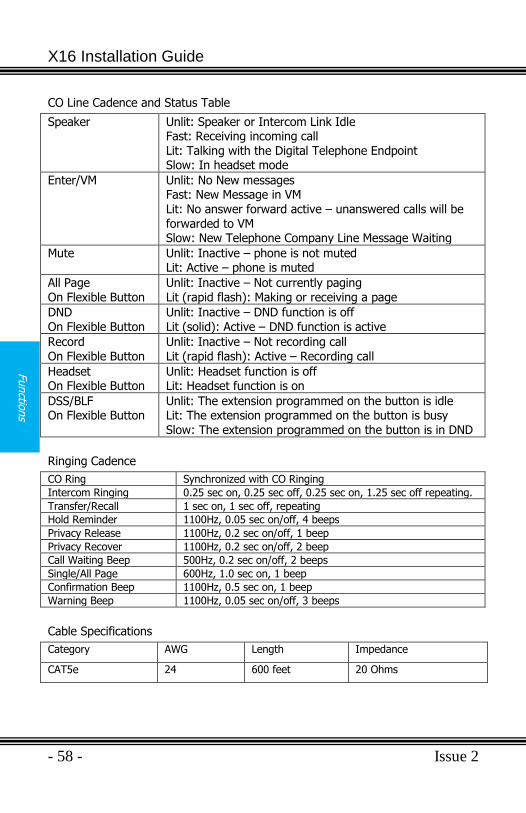
Functio
ns
CO Line Cadence and Status Table
Speaker Unlit: Speaker or Intercom Link Idle Fast: Receiving incoming call Lit: Talking with the Digital Telephone Endpoint Slow: In headset mode
Enter/VM Unlit: No New messages Fast: New Message in VM Lit: No answer forward active – unanswered calls will be forwarded to VM Slow: New Telephone Company Line Message Waiting
Mute Unlit: Inactive – phone is not muted Lit: Active – phone is muted
All Page On Flexible Button
Unlit: Inactive – Not currently paging Lit (rapid flash): Making or receiving a page
DND On Flexible Button
Unlit: Inactive – DND function is off Lit (solid): Active – DND function is active
Record On Flexible Button
Unlit: Inactive – Not recording call Lit (rapid flash): Active – Recording call
Headset On Flexible Button
Unlit: Headset function is off Lit: Headset function is on
DSS/BLF On Flexible Button
Unlit: The extension programmed on the button is idle Lit: The extension programmed on the button is busy Slow: The extension programmed on the button is in DND
Ringing Cadence
CO Ring Synchronized with CO Ringing
Intercom Ringing 0.25 sec on, 0.25 sec off, 0.25 sec on, 1.25 sec off repeating.
Transfer/Recall 1 sec on, 1 sec off, repeating
Hold Reminder 1100Hz, 0.05 sec on/off, 4 beeps
Privacy Release 1100Hz, 0.2 sec on/off, 1 beep
Privacy Recover 1100Hz, 0.2 sec on/off, 2 beep
Call Waiting Beep 500Hz, 0.2 sec on/off, 2 beeps
Single/All Page 600Hz, 1.0 sec on, 1 beep
Confirmation Beep 1100Hz, 0.5 sec on, 1 beep
Warning Beep 1100Hz, 0.05 sec on/off, 3 beeps
Cable Specifications
Category AWG Length Impedance
CAT5e 24 600 feet 20 Ohms
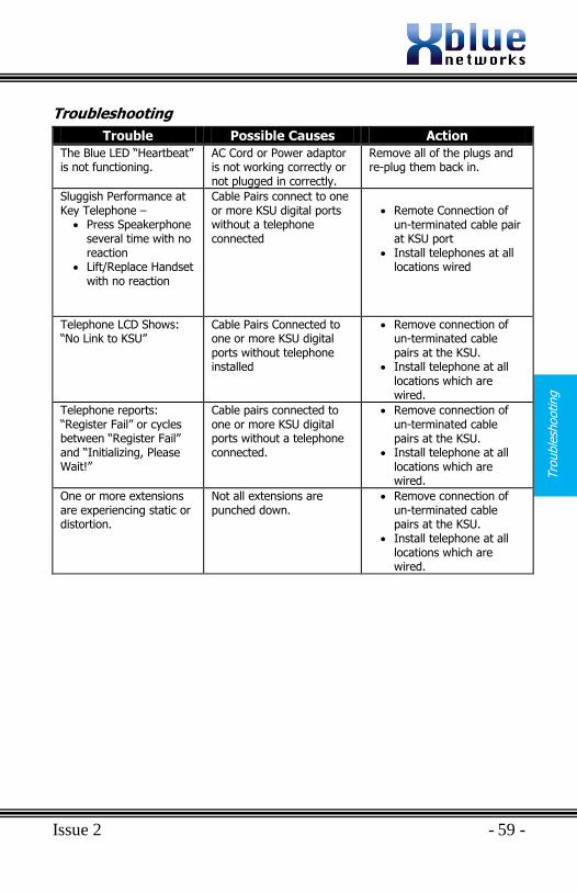
Issue 2 - 59 -
Tro
uble
shooting
Troubleshooting
Trouble Possible Causes Action
The Blue LED “Heartbeat” is not functioning.
AC Cord or Power adaptor is not working correctly or not plugged in correctly.
Remove all of the plugs and re-plug them back in.
Sluggish Performance at Key Telephone –
Press Speakerphone several time with no reaction
Lift/Replace Handset with no reaction
Cable Pairs connect to one or more KSU digital ports without a telephone connected
Remote Connection of
un-terminated cable pair at KSU port
Install telephones at all locations wired
Telephone LCD Shows: “No Link to KSU”
Cable Pairs Connected to one or more KSU digital ports without telephone installed
Remove connection of un-terminated cable pairs at the KSU.
Install telephone at all locations which are wired.
Telephone reports: “Register Fail” or cycles between “Register Fail” and “Initializing, Please Wait!”
Cable pairs connected to one or more KSU digital ports without a telephone connected.
Remove connection of un-terminated cable pairs at the KSU.
Install telephone at all locations which are wired.
One or more extensions are experiencing static or distortion.
Not all extensions are punched down.
Remove connection of un-terminated cable pairs at the KSU.
Install telephone at all locations which are wired.
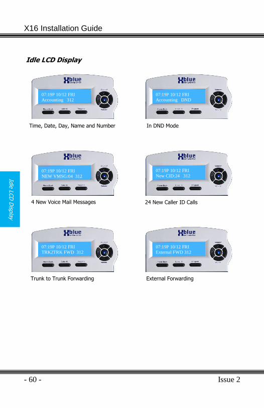
X16 Installation Guide
- 60 - Issue 2
Idle
LCD
Disp
lay
Idle LCD Display
07:19P 10/12 FRI
Accounting 312
07:19P 10/12 FRI
New CID:24 312 07:19P 10/12 FRI
NEW VMSG:04 312
07:19P 10/12 FRI
TRK2TRK FWD 312 07:19P 10/12 FRI
External FWD 312
07:19P 10/12 FRI
Accounting DND
Time, Date, Day, Name and Number In DND Mode
4 New Voice Mail Messages 24 New Caller ID Calls
Trunk to Trunk Forwarding External Forwarding
Issue 2 - 61 -
Voic
e M
ail
Opera
tion
Voice Mail Operation
The System comes equipped with a 4 channel auto attendant and voice mail system, which can answer up to 4 different calls simultaneously.
Programming for the auto attendant is found System Setup
Auto Attendant
The system can be programmed to answer in “Auto Attendant” mode. When “Auto Attend Ring”, found in “System Setup Mail System” is set
to “AA only” only the Auto Attendant will ring. No other telephone
extensions will ring. Once the Auto Attendant answers the call, the caller
may dial the desired extension number.
Personal Mailbox
Each extension is automatically assigned a personal mailbox, which is used to play a personal greeting or outgoing message (OGM) and record a personal message for that user. At default the center navigation key is lit solid, which confirms that the extension is forwarded to the users‟ personal voice mailbox.
Memo Recording
Each extension can press their record button to record a memo or a conversation that is taking place in the office.
1) Press the record button
2) Press the center navigation button to begin, and end recording. 3) The memo will be stored as a new message.
One Touch Record
While speaking to an outside party, the user may press their record button and record the current conversation. The message will be saved as a new voice mail message in the user‟s personal mailbox.
AUTO MUTE
Record Memo Yes?
AUTO MUTE
Record Memo
Stop
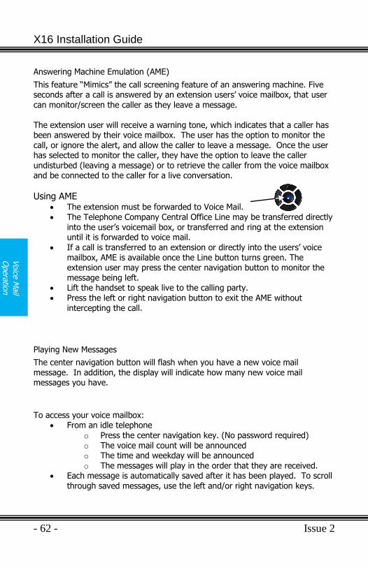
X16 Installation Guide
- 62 - Issue 2
Voice
Opera
tion
Answering Machine Emulation (AME)
This feature “Mimics” the call screening feature of an answering machine. Five seconds after a call is answered by an extension users‟ voice mailbox, that user can monitor/screen the caller as they leave a message. The extension user will receive a warning tone, which indicates that a caller has been answered by their voice mailbox. The user has the option to monitor the call, or ignore the alert, and allow the caller to leave a message. Once the user has selected to monitor the caller, they have the option to leave the caller undisturbed (leaving a message) or to retrieve the caller from the voice mailbox and be connected to the caller for a live conversation.
Using AME The extension must be forwarded to Voice Mail. The Telephone Company Central Office Line may be transferred directly
into the user‟s voicemail box, or transferred and ring at the extension until it is forwarded to voice mail.
If a call is transferred to an extension or directly into the users‟ voice mailbox, AME is available once the Line button turns green. The extension user may press the center navigation button to monitor the message being left.
Lift the handset to speak live to the calling party. Press the left or right navigation button to exit the AME without
intercepting the call.
Playing New Messages
The center navigation button will flash when you have a new voice mail message. In addition, the display will indicate how many new voice mail messages you have.
To access your voice mailbox:
From an idle telephone
o Press the center navigation key. (No password required) o The voice mail count will be announced o The time and weekday will be announced o The messages will play in the order that they are received.
Each message is automatically saved after it has been played. To scroll through saved messages, use the left and/or right navigation keys.
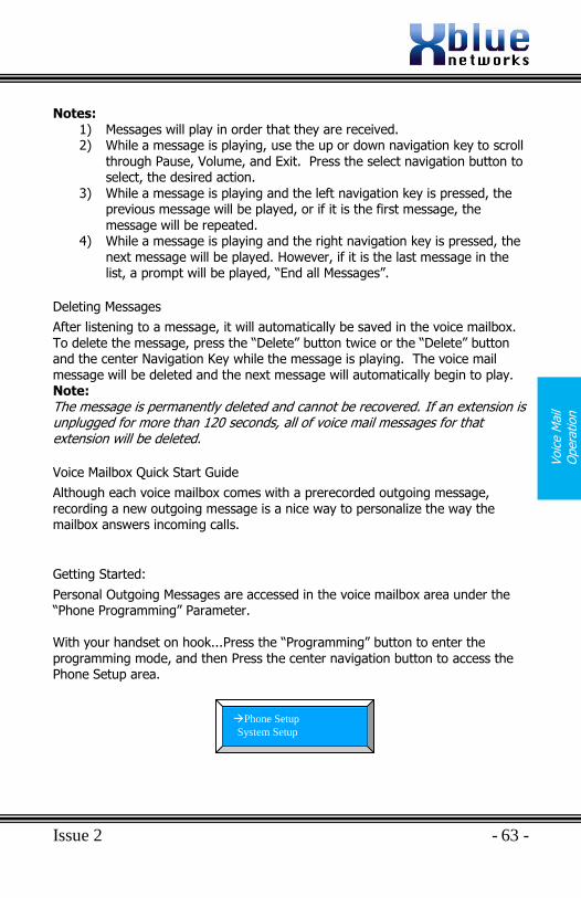
Issue 2 - 63 -
Voic
e M
ail
Opera
tion
Notes: 1) Messages will play in order that they are received. 2) While a message is playing, use the up or down navigation key to scroll
through Pause, Volume, and Exit. Press the select navigation button to select, the desired action.
3) While a message is playing and the left navigation key is pressed, the previous message will be played, or if it is the first message, the message will be repeated.
4) While a message is playing and the right navigation key is pressed, the next message will be played. However, if it is the last message in the list, a prompt will be played, “End all Messages”.
Deleting Messages
After listening to a message, it will automatically be saved in the voice mailbox. To delete the message, press the “Delete” button twice or the “Delete” button and the center Navigation Key while the message is playing. The voice mail message will be deleted and the next message will automatically begin to play. Note: The message is permanently deleted and cannot be recovered. If an extension is unplugged for more than 120 seconds, all of voice mail messages for that extension will be deleted.
Voice Mailbox Quick Start Guide
Although each voice mailbox comes with a prerecorded outgoing message, recording a new outgoing message is a nice way to personalize the way the mailbox answers incoming calls.
Getting Started:
Personal Outgoing Messages are accessed in the voice mailbox area under the “Phone Programming” Parameter. With your handset on hook...Press the “Programming” button to enter the programming mode, and then Press the center navigation button to access the Phone Setup area.
AUTO MUTE
Phone Setup
System Setup
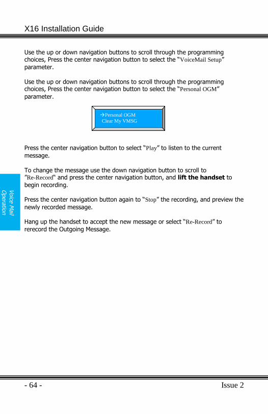
X16 Installation Guide
- 64 - Issue 2
Voice
Opera
tion
Use the up or down navigation buttons to scroll through the programming choices, Press the center navigation button to select the “VoiceMail Setup”
parameter. Use the up or down navigation buttons to scroll through the programming choices, Press the center navigation button to select the “Personal OGM”
parameter. Press the center navigation button to select “Play” to listen to the current
message. To change the message use the down navigation button to scroll to ”Re-Record“ and press the center navigation button, and lift the handset to
begin recording. Press the center navigation button again to “Stop” the recording, and preview the
newly recorded message. Hang up the handset to accept the new message or select “Re-Record” to
rerecord the Outgoing Message.
AUTO MUTE
Personal OGM
Clear My VMSG
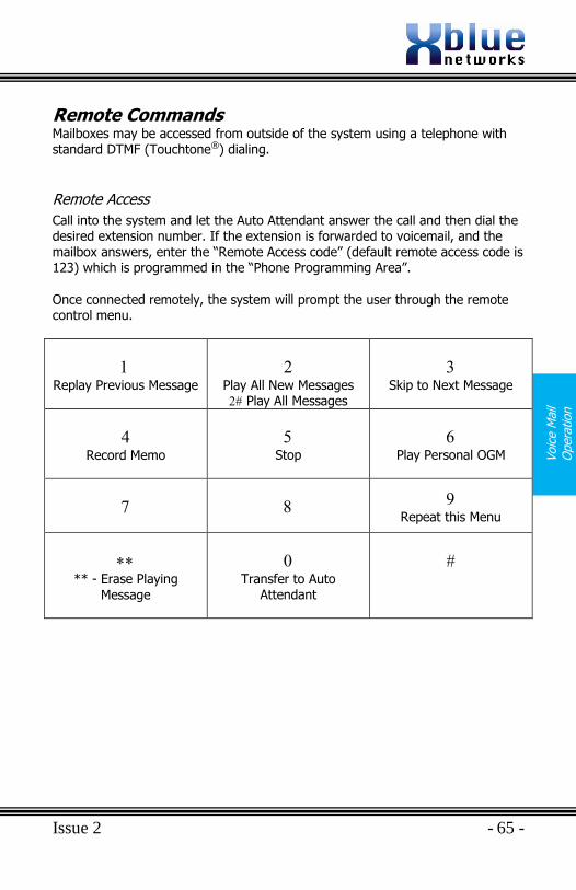
Issue 2 - 65 -
Voic
e M
ail
Opera
tion
Remote Commands Mailboxes may be accessed from outside of the system using a telephone with standard DTMF (Touchtone®) dialing.
Remote Access
Call into the system and let the Auto Attendant answer the call and then dial the desired extension number. If the extension is forwarded to voicemail, and the mailbox answers, enter the “Remote Access code” (default remote access code is 123) which is programmed in the “Phone Programming Area”.
Once connected remotely, the system will prompt the user through the remote control menu.
Replay Previous Message
Play All New Messages Play All Messages
Skip to Next Message
Record Memo
Stop
Play Personal OGM
Repeat this Menu
** - Erase Playing
Message
Transfer to Auto
Attendant
X16 Installation Guide
- 66 - Issue 2
Index
Index
—A—
All Call Paging, 32
All Page, 23, 44, 57 Answering Machine Emulation,
23, 62 Auto Attendant, 23, 61
Off, 56
On, 56
Auto Mute, 29
—B—
Backlit Blue LCD Display, 24 Backlit LCD Display, 10, 24 Bridge Tap, 18
—C—
Cable Pair Colors, 17 Cable Run, 15 Call Forward, 28
External, 28
TRK2TRK, 28
Voice Mail, 28
Call Time, 24 Call Transfer
Extension, 35
Caller ID Call Waiting Caller ID, 24
Calling Hands-free, 30
Character Input Keyboard, 43 CO Line
Busy, 25
Idle, 25
Ringing, 25
Common Ringing, 56
Conference, 25, 44, 57 Express Conference, 33
Operation, 26
Conversation Record, 26
—D—
Daylight Savings, 26 Default Button Layout, 11 Direct Mailbox Transfer, 27 Direct Station Select, 27 Distinctive Ring Tone, 27 Distinctive Ringing, 27 DND, 27, 44, 57 Do Not Disturb, 27 DSS
DSS, 27
DSS/BLF Key, 44
DTMF Dialing, 35
—E—
Expansion Module Installation, 21, 22
Installing, 21
Express Conference, 26 Conference, 33
Extension Numbers, 17 External
Call Forward, 28
—F—
FCC Registration, 8 Feature Button
Programming, 33, 44
Feature Key, 44 Features, 9 Flash
CO Line, 28
Issue 2 - 67 -
Index
Flash Key, 44
Flash Timer, 28
Key, 57
Flexible Button Programming Steps, 45
Forward, 28 Functions
Cadence, 57
CO Line Cadence, 58
Functions, 57
Intercom Tone Cadences, 57, 58
Phone Book, 57
Ringing Cadence, 58
—H—
Hands-free Calling, 30
Hands-Free Calling, 29
Headset, 44, 57 Headset Activation, 30 Hearing Aid Compatible, 7 Hold, 30 Hot Dial Pad, 30
—I—
Idle Display, 60 Installation
CO Line, 14
Expansion Module, 21
Extension Numbering, 20
Location, 13
Telephone Endpoint, 17
Installing the system, 15 Intercom
Intercom Calling, 30
Intercom Paging, 30
Introduction, 9
—L—
Line Access Dial 9, 26
Line In Use, 30 Line Status Detection, 30
—M—
Meet Me Paging, 32
Memo Recording, 31, 61 Message Waiting
Telephone Company, 31
Multilingual Extension, 31 Music on Hold, 31 Mute, 32, 44, 57 Muted Ringing, 32, 34
—N—
Navigation Keys, 32 New Message Play, 32
—O—
One Touch Record, 26, 61 One-Way Paging, 32
—P—
Page All Call, 32
Paging Meet Me, 32
Part Numbers, 2 Password
Default, 47
Pause, 33, 44, 57 Personal Mailbox, 61 Phone Book Dialing, 33 Phone Setup, 53 Power up and Initialization, 20
X16 Installation Guide
- 68 - Issue 2
Index
Privacy Release, 33 Programmable Buttons, 33 Programmable Pause
Speed Dial Bins, 33
Programming, 37 Feature Buttons, 33, 44
Phone, 37
Phone Setup, 39
System, 37
System Setup, 47
Pulse Dialing, 35 Punch down, 19
—R—
Record, 44, 57 Redial, 44, 57 Redial Button, 33 Remote Access, 65 Remote Commands, 65 Reserved, 44 Ringer Equivalence, 8 Ringing, 56
Audible Indication, 34
Visual Indication, 34
Ringing Scenarios, 56 RJ11 connector, 14 RJ11 extension, 15 Room Monitor, 34
—S—
Set Relocation, 34 Speakerphone, 35 Speed Dial Bins, 35
Programmable Pause, 33
Speed Key, 44 Star Topology, 16
System Configuration and Layout, 12
System Programming, 54
—T—
Telephone Callouts, 10 Termination Box, 34 Time in Display, 35 Transfer, 35
Direct to Voice Mail, 35
TRK2TRK Forward, 28
—U—
Underwriters Laboratories, 7
—V—
Voice Mail Deleting Messages, 63
Getting Started, 63
Operation, 61
Personal Mailbox, 33
Playing New Messages, 62
Quick Start Guide, 63
Voice Mail, 36
Volume Intercom Handset, 36
Intercom Speakerphone, 35
Network Handset, 36
Network Speakerphone,
36
Ringing, 35
Volume Control, 34 Handset, 29
Headset, 29
—W—
Wall Mount, 22
Issue 2 - 69 -
Note
s:
Notes:
X16 Installation Guide
- 70 - Issue 2
Note
s:
Notes:

Issue 2 - 71 -
Note
s:
Notes:

X16 Installation Guide
- 72 - Issue 2
Note
s:
XBLUE Networks © Copyright 2007