Embed Size (px)
Citation preview
April 2001 XI S-1 NUREG-1801
XI.S1 ASME SECTION XI, SUBSECTION IWE
Program Description
10 CFR 50.55a imposes the inservice inspection (ISI) requirements of the American Society ofMechanical Engineers (ASME) Boiler and Pressure Vessel (B&PV) Code, Section XI,Subsection IWE for steel containments (Class MC) and steel liners for concrete containments(Class CC). The full scope of IWE includes steel containment shells and their integralattachments; steel liners for concrete containments and their integral attachments; containmenthatches and airlocks; seals, gaskets and moisture barriers; and pressure-retaining bolting. Thisevaluation covers both the 1992 Edition with the 1992 Addenda and the 1995 Edition with the1996 Addenda, as approved in 10 CFR 50.55a. ASME Code Section XI, Subsection IWE andthe additional requirements specified in 10 CFR 50.55a(b)(2) constitute an existing mandatedprogram applicable to managing aging of steel containments, steel liners of concretecontainments, and other containment components for license renewal.
The primary ISI method specified in IWE is visual examination (general visual, VT-3, VT-1).Limited volumetric examination (ultrasonic thickness measurement) and surface examination(e.g., liquid penetrant) may also be necessary in some instances. Bolt preload is checked byeither a torque or tension test. IWE specifies acceptance criteria, corrective actions, andexpansion of the inspection scope when degradation exceeding the acceptance criteria is found.
The evaluation of 10 CFR 50.55a and Subsection IWE as an aging management program(AMP) for license renewal is provided below.
Evaluation and Technical Basis
1. Scope of Program: Subsection IWE-1000 specifies the components of steel containmentsand steel liners of concrete containments within its scope. The components within the scopeof Subsection IWE are Class MC pressure-retaining components (steel containments) andtheir integral attachments; metallic shell and penetration liners of Class CC containmentsand their integral attachments; containment seals and gaskets; containment pressure-retaining bolting; and metal containment surface areas, including welds and base metal. Theconcrete portions of containments are inspected in accordance with Subsection IWL.
Subsection IWE exempts the following from examination:
(1) Components that are outside the boundaries of the containment as defined in the plant-specific design specification;
(2) Embedded or inaccessible portions of containment components that met therequirements of the original construction code of record;
(3) Components that become embedded or inaccessible as a result of vessel repair orreplacement, provided IWE-1232 and IWE-5220 are met; and
(4) Piping, pumps, and valves that are part of the containment system or that penetrate orare attached to the containment vessel (governed by IWB or IWC).
10 CFR 50.55a(b)(2)(ix) specifies additional requirements for inaccessible areas. It statesthat the licensee is to evaluate the acceptability of inaccessible areas when conditions existin accessible areas that could indicate the presence of or result in degradation to suchinaccessible areas. Examination requirements for containment supports are not within thescope of Subsection IWE.
NUREG-1801 XI S-2 April 2001
2. Preventive Action: No preventive actions are specified; Subsection IWE is a monitoringprogram.
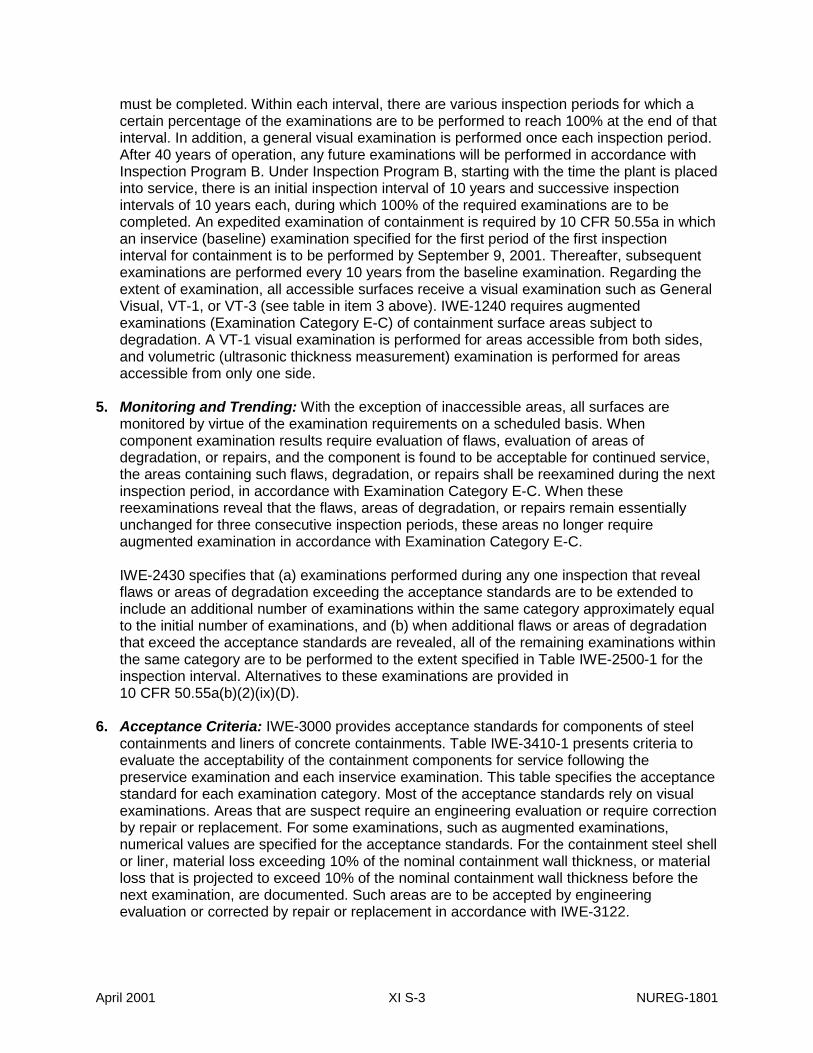
3. Parameters Monitored or Inspected: Table IWE-2500-1 specifies seven categories forexamination. The categories, parts examined, and examination methods are presented inthe following table. The first six examination categories (E-A through E-G) constitute the ISIrequirements of IWE. Examination category E-P references 10 CFR Part 50, Appendix Jleak rate testing. Appendix J leak rate testing is evaluated as a separate AMP for licenserenewal in XI.S4.
CATEGORY PARTS EXAMINED EXAMINATION METHODa
E-A Containment surfaces General visual, visual VT-3E-Bb Pressure retaining welds Visual VT-1E-C Containment surfaces
requiring augmentedexamination
Visual VT-1, volumetric
E-D Seals, gaskets, andmoisture barriers
Visual VT-3
E-Fb Pressure retainingdissimilar metal welds
Surface
E-G Pressure retaining bolting Visual VT-1, bolt torque ortension test
E-P All pressure-retainingcomponents (pressureretaining boundary,penetration bellows,airlocks, seals, andgaskets)
10 CFR Part 50, Appendix J(containment leak ratetesting)
a The applicable examination method (where multiple methods arelisted) depends on the particular subcategory within each category.
b These two categories are optional, in accordance with10 CFR 50.55a(b)(2)(ix)(C).
Table IWE-2500-1 references the applicable section in IWE-3500 that identifies the agingeffects that are evaluated. The parameters monitored or inspected depend on the particularexamination category. For Examination Category E-A, as an example, metallic surfaces(without coatings) are examined for evidence of cracking, discoloration, wear, pitting,excessive corrosion, arc strikes, gouges, surface discontinuities, dents, and other signs ofsurface irregularities. For Examination Category E-D, seals, gaskets, and moisture barriersare examined for wear, damage, erosion, tear, surface cracks, or other defects that mayviolate the leak-tight integrity.
4. Detection of Aging Effects: The frequency and scope of examination specified in10 CFR 50.55a and Subsection IWE ensure that aging effects would be detected beforethey would compromise the design-basis requirements. As indicated in IWE-2400, inserviceexaminations and pressure tests are performed in accordance with one of two inspectionprograms, A or B, on a specified schedule. Under Inspection Program A, there are fourinspection intervals (at 3, 10, 23, and 40 years) for which 100% of the required examinations
April 2001 XI S-3 NUREG-1801
must be completed. Within each interval, there are various inspection periods for which acertain percentage of the examinations are to be performed to reach 100% at the end of thatinterval. In addition, a general visual examination is performed once each inspection period.After 40 years of operation, any future examinations will be performed in accordance withInspection Program B. Under Inspection Program B, starting with the time the plant is placedinto service, there is an initial inspection interval of 10 years and successive inspectionintervals of 10 years each, during which 100% of the required examinations are to becompleted. An expedited examination of containment is required by 10 CFR 50.55a in whichan inservice (baseline) examination specified for the first period of the first inspectioninterval for containment is to be performed by September 9, 2001. Thereafter, subsequentexaminations are performed every 10 years from the baseline examination. Regarding theextent of examination, all accessible surfaces receive a visual examination such as GeneralVisual, VT-1, or VT-3 (see table in item 3 above). IWE-1240 requires augmentedexaminations (Examination Category E-C) of containment surface areas subject todegradation. A VT-1 visual examination is performed for areas accessible from both sides,and volumetric (ultrasonic thickness measurement) examination is performed for areasaccessible from only one side.
5. Monitoring and Trending: With the exception of inaccessible areas, all surfaces aremonitored by virtue of the examination requirements on a scheduled basis. Whencomponent examination results require evaluation of flaws, evaluation of areas ofdegradation, or repairs, and the component is found to be acceptable for continued service,the areas containing such flaws, degradation, or repairs shall be reexamined during the nextinspection period, in accordance with Examination Category E-C. When thesereexaminations reveal that the flaws, areas of degradation, or repairs remain essentiallyunchanged for three consecutive inspection periods, these areas no longer requireaugmented examination in accordance with Examination Category E-C.
IWE-2430 specifies that (a) examinations performed during any one inspection that revealflaws or areas of degradation exceeding the acceptance standards are to be extended toinclude an additional number of examinations within the same category approximately equalto the initial number of examinations, and (b) when additional flaws or areas of degradationthat exceed the acceptance standards are revealed, all of the remaining examinations withinthe same category are to be performed to the extent specified in Table IWE-2500-1 for theinspection interval. Alternatives to these examinations are provided in10 CFR 50.55a(b)(2)(ix)(D).
6. Acceptance Criteria: IWE-3000 provides acceptance standards for components of steelcontainments and liners of concrete containments. Table IWE-3410-1 presents criteria toevaluate the acceptability of the containment components for service following thepreservice examination and each inservice examination. This table specifies the acceptancestandard for each examination category. Most of the acceptance standards rely on visualexaminations. Areas that are suspect require an engineering evaluation or require correctionby repair or replacement. For some examinations, such as augmented examinations,numerical values are specified for the acceptance standards. For the containment steel shellor liner, material loss exceeding 10% of the nominal containment wall thickness, or materialloss that is projected to exceed 10% of the nominal containment wall thickness before thenext examination, are documented. Such areas are to be accepted by engineeringevaluation or corrected by repair or replacement in accordance with IWE-3122.
NUREG-1801 XI S-4 April 2001
7. Corrective Actions: Subsection IWE states that components whose examination resultsindicate flaws or areas of degradation that do not meet the acceptance standards listed inTable-3410-1 are acceptable if an engineering evaluation indicates that the flaw or area ofdegradation is nonstructural in nature or has no effect on the structural integrity of thecontainment. Except as permitted by 10 CFR 50.55a(b)(ix)(D), components that do not meetthe acceptance standards are subject to additional examination requirements, and thecomponents are repaired or replaced to the extent necessary to meet the acceptancestandards of IWE-3000. For repair of components within the scope of Subsection IWE, IWE-3124 states that repairs and reexaminations are to comply with IWA-4000. IWA-4000provides repair specifications for pressure retaining components including metalcontainments and metallic liners of concrete containments. As discussed in the appendix tothis report, the staff finds the requirements of 10 CFR Part 50, Appendix B, acceptable toaddress corrective actions.
8. Confirmation Process: When areas of degradation are identified, an evaluation isperformed to determine whether repair or replacement is necessary. If the evaluationdetermines that repair or replacement is necessary, Subsection IWE specifies confirmationthat appropriate corrective actions have been completed and are effective. Subsection IWEstates that repairs and reexaminations are to comply with the requirements of IWA-4000.Reexaminations are conducted in accordance with the requirements of IWA-2200, and therecorded results are to demonstrate that the repair meets the acceptance standards setforth in Table IWE-3410-1. As discussed in the appendix to this report, the staff finds therequirements of 10 CFR Part 50, Appendix B, acceptable to address the confirmationprocess.
9. Administrative Controls: IWA-6000 provides specifications for the preparation, submittal,and retention of records and reports. As discussed in the appendix to this report, the stafffinds the requirements of 10 CFR Part 50, Appendix B, acceptable to address administrativecontrols.
10. Operating Experience: ASME Section XI, Subsection IWE was incorporated into10 CFR 50.55a in 1996. Prior to this time, operating experience pertaining to degradation ofsteel components of containment was gained through the inspections required by 10 CFRPart 50, Appendix J and ad hoc inspections conducted by licensees and the NuclearRegulatory Commission (NRC). NRC Information Notice (INs) 86-99, 88-82 and 89-79described occurrences of corrosion in steel containment shells. NRC Generic Letter(GL) 87-05 addressed the potential for corrosion of boiling water reactor (BWR) Mark I steeldrywells in the “sand pocket region.” More recently, NRC IN 97-10 identified specificlocations where concrete containments are susceptible to liner plate corrosion. The programis to consider the liner plate and containment shell corrosion concerns described in thesegeneric communications. Implementation of the ISI requirements of Subsection IWE, inaccordance with 10 CFR 50.55a, is a necessary element of aging management for steelcomponents of steel and concrete containments through the period of extended operation.
References
10 CFR Part 50, Appendix J, Primary Reactor Containment Leakage Testing for Water-CooledPower Reactors, Office of the Federal Register, National Archives and RecordsAdministration, 2000.
April 2001 XI S-5 NUREG-1801
10 CFR 50.55a, Codes and Standards, Office of the Federal Register, National Archives andRecords Administration, 2000.
ASME Section XI, Rules for Inservice Inspection of Nuclear Power Plant Components,Subsection IWA, General Requirements, 1992 Edition with 1992 Addenda; 1995 Edition with1996 Addenda, The ASME Boiler and Pressure Vessel Code, The American Society ofMechanical Engineers, New York, NY.
ASME Section XI, Rules for Inservice Inspection of Nuclear Power Plant Components,Subsection IWB, Requirements for Class 1 Components of Light-Water Cooled PowerPlants, 1992 Edition with 1992 Addenda; 1995 Edition with 1996 Addenda, The ASMEBoiler and Pressure Vessel Code, The American Society of Mechanical Engineers, NewYork, NY.
ASME Section XI, Rules for Inservice Inspection of Nuclear Power Plant Components,Subsection IWC, Requirements for Class 2 Components of Light-Water Cooled PowerPlants, 1992 Edition with 1992 Addenda; 1995 Edition with 1996 Addenda, The ASMEBoiler and Pressure Vessel Code, The American Society of Mechanical Engineers, NewYork, NY.
ASME Section XI, Rules for Inservice Inspection of Nuclear Power Plant Components,Subsection IWE, Requirements for Class MC and Metallic Liners of Class CC Componentsof Light-Water Cooled Power Plants, 1992 Edition with 1992 Addenda; 1995 Edition with1996 Addenda, The ASME Boiler and Pressure Vessel Code, The American Society ofMechanical Engineers, New York, NY.
ASME Section XI, Rules for Inservice Inspection of Nuclear Power Plant Components,Subsection IWL, Requirements for Class CC Concrete Components of Light-Water CooledPower Plants, 1992 Edition with 1992 Addenda; 1995 Edition with 1996 Addenda, TheASME Boiler and Pressure Vessel Code, The American Society of Mechanical Engineers,New York, NY.
NRC Generic Letter 87-05, Request for Additional Information Assessment of LicenseeMeasures to Mitigate and/or Identify Potential Degradation of Mark I Drywells, U.S. NuclearRegulatory Commission, March 12, 1987.
NRC Information Notice 86-99, Degradation of Steel Containments, U.S. Nuclear RegulatoryCommission, December 8, 1986 and Supplement 1, February 14, 1991.
NRC Information Notice 88-82, Torus Shells with Corrosion and Degraded Coatings in BWRContainments, U.S. Nuclear Regulatory Commission, October 14,1988 and Supplement 1,May 2, 1989.
NRC Information Notice 89-79, Degraded Coatings and Corrosion of Steel ContainmentVessels, U.S. Nuclear Regulatory Commission, December 1, 1989 and Supplement 1, June29, 1989.
NRC Information Notice 97-10, Liner Plate Corrosion in Concrete Containment, U.S. NuclearRegulatory Commission, March 13, 1997.
NUREG-1801 XI S-6 April 2001
XI.S2 ASME SECTION XI, SUBSECTION IWL
Program Description
10 CFR 50.55a imposes the examination requirements of the American Society of MechanicalEngineers (ASME) Boiler and Pressure Vessel (B&PV) Code, Section XI, Subsection IWL forreinforced and prestressed concrete containments (Class CC). The scope of IWL includesreinforced concrete and unbonded post-tensioning systems. This evaluation covers both the1992 Edition with the 1992 Addenda and the 1995 Edition with the 1996 Addenda, as approvedin 10 CFR 50.55a. ASME Code Section XI, Subsection IWL and the additional requirementsspecified in 10 CFR 50.55a(b)(2) constitute an existing mandated program applicable tomanaging aging of containment reinforced concrete and unbonded post-tensioning systems forlicense renewal.
The primary inspection method specified in IWL is visual examination (VT-3C, VT-1, VT-1C).For prestressed containments, tendon wires are tested for yield strength, ultimate tensilestrength, and elongation. Tendon corrosion protection medium is analyzed for alkalinity, watercontent, and soluble ion concentrations. Prestressing forces are measured in selected sampletendons. IWL specifies acceptance criteria, corrective actions, and expansion of the inspectionscope when degradation exceeding the acceptance criteria is found.
The evaluation of 10 CFR 50.55a and Subsection IWL as an aging management program(AMP) for license renewal is provided below.
Evaluation and Technical Basis
1. Scope of Program: Subsection IWL-1000 specifies the components of concretecontainments within its scope. The components within the scope of Subsection IWL arereinforced concrete and unbonded post-tensioning systems of Class CC containments, asdefined by CC-1000. Subsection IWL exempts from examination portions of the concretecontainment that are inaccessible (e.g., concrete covered by liner, foundation material, orbackfill, or obstructed by adjacent structures or other components). 10 CFR 50.55a(b)(2)(viii)specifies additional requirements for inaccessible areas. It states that the licensee is toevaluate the acceptability of concrete in inaccessible areas when conditions exist inaccessible areas that could indicate the presence of or result in degradation to suchinaccessible areas. Steel liners for concrete containments and their integral attachments arenot within the scope of Subsection IWL, but are included within the scope of SubsectionIWE.
2. Preventive Action: No preventive actions are specified; Subsection IWL is a monitoringprogram. If a coating program is currently credited for managing the effects of aging ofconcrete surfaces, then the program is to be continued during the period of extendedoperation.
3. Parameters Monitored or Inspected: Table IWL-2500-1 specifies two categories forexamination of concrete surfaces: Category L-A for all concrete surfaces and Category L-Bfor concrete surfaces surrounding tendon anchorages. Both of these categories rely onvisual examination methods. Concrete surfaces are examined for evidence of damage ordegradation, such as concrete cracks. IWL-2510 specifies that concrete surfaces areexamined for conditions indicative of degradation, such as those defined in ACI 201.1R-77.Table IWL-2500-1 also specifies Category L-B for test and examination requirements for
April 2001 XI S-7 NUREG-1801
unbonded post tensioning systems. Tendon anchorage and wires or strands are visuallyexamined for cracks, corrosion, and mechanical damage. Tendon wires or strands are alsotested for yield strength, ultimate tensile strength, and elongation. Tendon corrosionprotection medium is tested by analysis for alkalinity, water content, and soluble ionconcentrations.
4. Detection of Aging Effects: The frequency and scope of examinations specified in10 CFR 50.55a and Subsection IWL ensure that aging effects would be detected beforethey would compromise the design-basis requirements. The frequency of inspection isspecified in IWL-2400. Concrete inspections are performed in accordance with ExaminationCategory L-A. Under Subsection IWL, inservice inspections for concrete and unbondedpost-tensioning systems are required at one, three, and five years following the structuralintegrity test. Thereafter, inspections are performed at five-year intervals. For sites with twoplants, the schedule for inservice inspection is provided in IWL-2421. In the case of tendons,only a sample of the tendons of each tendon type requires examination at each inspection.The tendons to be examined during an inspection are selected on a random basis. TableIWL-2521-1 specifies the number of tendons to be selected for each type (e.g., hoop,vertical, dome, helical, and inverted U) for each inspection period. The minimum number ofeach tendon type selected for inspection varies from 2 to 4%. Regarding detection methodsfor aging effects, all concrete surfaces receive a visual VT-3C examination. Selected areas,such as those that indicate suspect conditions and areas surrounding tendon anchorages,receive a more rigorous VT-1 or VT-1C examination. Prestressing forces in sample tendonsare measured. In addition, one sample tendon of each type is detensioned. A single wire orstrand is removed from each detensioned tendon for examination and testing. These visualexamination methods and testing would identify the aging effects of accessible concretecomponents and prestressing systems in concrete containments.
5. Monitoring and Trending: Except in inaccessible areas, all concrete surfaces aremonitored on a regular basis by virtue of the examination requirements. For prestressedcontainments, trending of prestressing forces in tendons is required in accordance withparagraph (b)(2)(viii) of 10 CFR 50.55a. In addition to the random sampling used for tendonexamination, one tendon of each type is selected from the first-year inspection sample anddesignated as a common tendon. Each common tendon is then examined during eachinspection. This procedure provides monitoring and trending information over the life of theplant. 10 CFR 50.55a and Subsection IWL also require that prestressing forces in allinspection sample tendons be measured by lift-off tests and compared with acceptancestandards based on the predicted force for that type of tendon over its life.
6. Acceptance Criteria: IWL-3000 provides acceptance criteria for concrete containments. Forconcrete surfaces, the acceptance criteria rely on the determination of the "ResponsibleEngineer" (as defined by the ASME Code) regarding whether there is any evidence ofdamage or degradation sufficient to warrant further evaluation or repair. The acceptancecriteria are qualitative; guidance is provided in IWL-2510, which references ACI 201.1R-77for identification of concrete degradation. IWL-2320 requires that the Responsible Engineerbe a registered professional engineer experienced in evaluating the inservice condition ofstructural concrete and knowledgeable of the design and construction codes and othercriteria used in design and construction of concrete containments. Quantitative acceptancecriteria based on the "Evaluation Criteria" provided in Chapter 5 of ACI 349.3R may also beused to augment the qualitative assessment of the responsible engineer. The acceptancestandards for the unbonded post-tensioning system are quantitative in nature. For the post-tensioning system, quantitative acceptance criteria are given for tendon force and
NUREG-1801 XI S-8 April 2001
elongation, tendon wire or strand samples, and corrosion protection medium.10 CFR 50.55a and Subsection IWL do not define the method for calculating predictedtendon prestressing forces for comparison to the measured tendon lift-off forces. Thepredicted tendon forces are to be calculated in accordance with Regulatory Guide 1.35.1,which provides an acceptable methodology for use through the period of extendedoperation.
7. Corrective Actions: Subsection IWL specifies that items for which examination results donot meet the acceptance standards are to be evaluated in accordance with IWL-3300"Evaluation" and described in an engineering evaluation report. The report is to include anevaluation of whether the concrete containment is acceptable without repair of the item andif repair is required, the extent, method, and completion date of the repair or replacement.The report also identifies the cause of the condition and the extent, nature, and frequency ofadditional examinations. Subsection IWL also provides repair procedures to follow in IWL-4000. This includes requirements for the concrete repair, repair of reinforcing steel, andrepair of the post-tensioning system. As discussed in the appendix to this report, the stafffinds the requirements of 10 CFR Part 50, Appendix B, acceptable to address correctiveactions.
8. Confirmation Process: When areas of degradation are identified, an evaluation isperformed to determine whether repair or replacement is necessary. As part of thisevaluation, IWL-3300 specifies that the engineering evaluation report include the extent,nature, and frequency of additional examinations. IWL-4000 specifies the requirements forexamination of areas that are repaired. Pressure tests following repair or modifications arein accordance with IWL-5000. As discussed in the appendix to this report, the staff finds therequirements of 10 CFR Part 50, Appendix B, acceptable to address the confirmationprocess.
9. Administrative Controls: IWA-1400 specifies the preparation of plans, schedules, andinservice inspection summary reports. In addition, written examination instructions andprocedures, verification of qualification level of personnel who perform the examinations,and documentation of a quality assurance program are specified. IWA-6000 specificallycovers the preparation, submittal, and retention of records and reports. As discussed in theappendix to this report, the staff finds the requirements of 10 CFR Part 50, Appendix B,acceptable to address administrative controls.
10. Operating Experience: ASME Section XI, Subsection IWL was incorporated into10 CFR 50.55a in 1996. Prior to this time, operating experience pertaining to degradation ofreinforced concrete and prestressing systems in concrete containments was gained throughthe inspections required by 10 CFR Part 50, Appendix J and ad hoc inspections conductedby licensees and the Nuclear Regulatory Commission (NRC). Recently, NRC InformationNotice (IN) 99-10 described occurrences of degradation in prestressing systems. Theprogram is to consider the degradation concerns described in this generic communication.Implementation of Subsection IWL, in accordance with 10 CFR 50.55a, is a necessaryelement of aging management for concrete containments through the period of extendedoperation.
April 2001 XI S-9 NUREG-1801
References
10 CFR Part 50, Appendix J, Primary Reactor Containment Leakage Testing for Water-CooledPower Reactors, Office of the Federal Register, National Archives and RecordsAdministration, 2000.
10 CFR 50.55a, Codes and Standards, Office of the Federal Register, National Archives andRecords Administration, 2000.
ACI Standard 201.1R-77, Guide for Making a Condition Survey of Concrete in Service,American Concrete Institute.
ACI Standard 349.3R-96, Evaluation of Existing Nuclear Safety-Related Concrete Structures,American Concrete Institute.
ASME Section XI, Rules for Inservice Inspection of Nuclear Power Plant Components,Subsection IWA, General Requirements, 1992 Edition with 1992 Addenda; 1995 Edition with1996 Addenda, The ASME Boiler and Pressure Vessel Code, The American Society ofMechanical Engineers, New York, NY.
ASME Section XI, Rules for Inservice Inspection of Nuclear Power Plant Components,Subsection IWE, Requirements for Class MC and Metallic Liners of Class CC Componentsof Light-Water Cooled Power Plants, 1992 Edition with 1992 Addenda; 1995 Edition with1996 Addenda, The ASME Boiler and Pressure Vessel Code, The American Society ofMechanical Engineers, New York, NY.
ASME Section XI, Rules for Inservice Inspection of Nuclear Power Plant Components,Subsection IWL, Requirements for Class CC Concrete Components of Light-Water CooledPower Plants, 1992 Edition with 1992 Addenda; 1995 Edition with 1996 Addenda, TheASME Boiler and Pressure Vessel Code, The American Society of Mechanical Engineers,New York, NY.
NRC Information Notice 99-10, Revision 1, Degradation of Prestressing Tendon Systems inPrestressed Concrete Containment, U.S. Nuclear Regulatory Commission, October 7, 1999.
NUREG-1801 XI S-10 April 2001
XI.S3 ASME SECTION XI, SUBSECTION IWF
Program Description
10 CFR 50.55a imposes the inservice inspection (ISI) requirements of the American Society ofMechanical Engineers (ASME) Boiler and Pressure Vessel Code, Section XI, for Class 1, 2, 3,and MC piping and components and their associated supports. Inservice inspection of supportsfor ASME piping and components is addressed in Section XI, Subsection IWF. This evaluationcovers the 1989 Edition through the 1995 Edition and addenda through the 1996 Addenda, asapproved in 10 CFR 50.55a. ASME Code Section XI, Subsection IWF constitutes an existingmandated program applicable to managing aging of ASME Class 1, 2, 3, and MC supports forlicense renewal.
The IWF scope of inspection for supports is based on sampling of the total support population.The sample size varies depending on the ASME Class. The largest sample size is specified forthe most critical supports (ASME Class 1). The sample size decreases for the less criticalsupports (ASME Class 2 and 3). Discovery of support deficiencies during regularly scheduledinspections triggers an increase of the inspection scope, in order to ensure that the full extent ofdeficiencies is identified. The primary inspection method employed is visual examination.Degradation that potentially compromises support function or load capacity is identified forevaluation. IWF specifies acceptance criteria and corrective actions. Supports requiringcorrective actions are re-examined during the next inspection period.
The evaluation of Subsection IWF as an aging management program (AMP) for license renewalis provided below.
Evaluation and Technical Basis
1. Scope of Program: For Class 1 piping and component supports, Subsection IWF(1989 edition) refers to Subsection IWB for the inspection scope and schedule. According toTable IWB-2500-1, only 25% of nonexempt supports are subject to examination. Supportsexempt from examination are the supports for piping systems that are exempt fromexamination, according to pipe diameter or service. The same supports are inspected ineach 10-year inspection interval. For Class 2, 3, and MC piping and component supports,Subsection IWF (1989 edition) refers to Subsections IWC, IWD, and IWE for the inspectionscope and schedule. According to Table IWC-2500-1, 7.5% of nonexempt supports aresubject to examination for Class 2 systems. The same supports are inspected in each10-year inspection interval. No specific numerical percentages are identified in SubsectionsIWD and IWE for Class 3 and Class MC, respectively.
Starting with the 1990 addenda to the 1989 edition, the scope of Subsection IWF wasrevised. The required percentages of each type of nonexempt support subject toexamination were incorporated into Table IWF-2500-1. The revised percentages are 25% ofClass 1 nonexempt piping supports, 15% of Class 2 nonexempt piping supports, 10% ofClass 3 nonexempt piping supports, and 100% of supports other than piping supports (Class1, 2, 3, and MC). For pipe supports, the total sample consists of supports from each system(such as main steam, feedwater, residual heat removal), where the individual sample sizesare proportional to the total number of nonexempt supports of each type and function withineach system. For multiple components other than piping, within a system of similar design,function, and service, the supports of only one of the multiple components are required to be
April 2001 XI S-11 NUREG-1801
examined. To the extent practical, the same supports selected for examination during thefirst inspection interval are examined during each successive inspection interval.
2. Preventive Action: No preventive actions are specified; Subsection IWF is an inspectionprogram.
3. Parameters Monitored or Inspected: IWF specifies visual examination (VT-3) of supports.The parameters monitored or inspected include corrosion; deformation; misalignment;improper clearances; improper spring settings; damage to close tolerance machined orsliding surfaces; and missing, detached, or loosened support items. The visual inspectionwould be expected to identify relatively large cracks.
Table IWF-2500-1 (1989 edition) specifies examination of the following:
(F1.10) Mechanical connections to pressure-retaining components and building structure;(F1.20) Weld connections to building structure;(F1.30) Weld and mechanical connections at intermediate joints in multi-connected integral
and nonintegral supports;(F1.40) Clearances of guides and stops, alignment of supports, and assembly of support
items;(F1.50) Spring supports and constant load supports;(F1.60) Sliding surfaces;(F1.70) Hot or cold position of spring supports and constant load supports.
(Starting with the 1990 addenda, these items are listed in paragraph IWF-2500.)
4. Detection of Aging Effects: VT-3 visual examination is specified in Table IWF-2500-1. Thecomplete inspection scope is repeated every 10-year inspection interval. The qualified VT-3inspector uses judgment in assessing general corrosion; observed degradation isdocumented if loss of structural capacity is suspected.
5. Monitoring and Trending: There is no requirement to monitor or report progressive, time-dependent degradation. Unacceptable conditions, according to IWF-3400, are noted forcorrection or further evaluation.
6. Acceptance Criteria: The acceptance standards for visual examination are specified inIWF-3400. In IWF-3410(b)(5), "roughness or general corrosion which does not reduce theload bearing capacity of the support" is given as an example of a "non-relevant condition,”which requires no further action. IWF-3410(a) identifies the following conditions asunacceptable:
(i) deformations or structural degradations of fasteners, springs, clamps, or other supportitems;
(ii) missing, detached, or loosened support items;(iii) arc strikes, weld spatter, paint, scoring, roughness, or general corrosion on close
tolerance machined or sliding surfaces;(iv) improper hot or cold positions of spring supports and constant load supports;(v) misalignment of supports;(vi) improper clearances of guides and stops.
NUREG-1801 XI S-12 April 2001
Identification of unacceptable conditions triggers an expansion of the inspection scope, inaccordance with IWF-2430, and reexamination of the supports requiring corrective actionsduring the next inspection period, in accordance with IWF-2420(b).
7. Corrective Actions: In accordance with IWF-3122, supports containing unacceptable conditions are evaluated or tested, or corrected before returning to service. Corrective actions are delineated in IWF-3122.2. IWF-3122.3 provides an alternative for evaluation or testing, to substantiate structural integrity and/or functionality. As discussed in the appendix to this report, the staff finds the requirements of 10 CFR Part 50, Appendix B, acceptable to address corrective actions.
8. Confirmation Process: As discussed in the appendix to this report, the staff finds therequirements of 10 CFR Part 50, Appendix B, acceptable to address the confirmationprocess.
9. Administrative Controls: As discussed in the appendix to this report, the staff finds therequirements of 10 CFR Part 50, Appendix B, acceptable to address administrative controls.
10. Operating Experience: To date, IWF sampling inspections have been effective inmanaging aging effects for ASME Class 1, 2, 3, and MC supports. There is reasonableassurance that the Subsection IWF inspection program will be effective through the periodof extended operation.
References
10 CFR 50.55a, Codes and Standards, Office of the Federal Register, National Archives andRecords Administration, January 2000.
ASME Section XI, Rules for Inservice Inspection of Nuclear Power Plant Components,Subsection IWB, Requirements for Class 1 Components of Light-Water Cooled PowerPlants, 1989 Edition. The ASME Boiler and Pressure Vessel Code, The American Society ofMechanical Engineers, New York, NY.
ASME Section XI, Rules for Inservice Inspection of Nuclear Power Plant Components,Subsection IWC, Requirements for Class 2 Components of Light-Water Cooled PowerPlants, 1989 Edition. The ASME Boiler and Pressure Vessel Code, The American Society ofMechanical Engineers, New York, NY.
ASME Section XI, Rules for Inservice Inspection of Nuclear Power Plant Components,Subsection IWD, Requirements for Class 3 Components of Light-Water Cooled PowerPlants, 1989 Edition. The ASME Boiler and Pressure Vessel Code, The American Society ofMechanical Engineers, New York, NY.
ASME Section XI, Rules for Inservice Inspection of Nuclear Power Plant Components,Subsection IWE, Requirements for Class MC and Metallic Liners of Class CC Componentsof Light-Water Cooled Power Plants, 1989 Edition. The ASME Boiler and Pressure VesselCode, The American Society of Mechanical Engineers, New York, NY.
April 2001 XI S-13 NUREG-1801
ASME Section XI, Rules for Inservice Inspection of Nuclear Power Plant Components,Subsection IWF, Requirements for Class 1, 2, 3, and MC Component Supports of Light-Water Cooled Power Plants, 1989 Edition through the 1995 Edition with 1996 Addenda. TheASME Boiler and Pressure Vessel Code, The American Society of Mechanical Engineers,New York, NY.
NUREG-1801 XI S-14 April 2001
XI.S4 10 CFR PART 50, APPENDIX J
Program Description
As described in 10 CFR Part 50, Appendix J, containment leak rate tests are required "to assurethat (a) leakage through the primary reactor containment and systems and componentspenetrating primary containment shall not exceed allowable leakage rate values as specified inthe technical specifications or associated bases and (b) periodic surveillance of reactorcontainment penetrations and isolation valves is performed so that proper maintenance andrepairs are made during the service life of the containment, and systems and componentspenetrating primary containment."
Appendix J provides two options, A and B, either of which can be chosen to meet therequirements of a containment LRT program. Under Option A, all of the testing must beperformed on a periodic interval. Option B is a performance-based approach. Some of thedifferences between these options are discussed below, and more detailed information forOption B is provided in the Nuclear Regulatory Commission (NRC) Regulatory Guide(RG) 1.163 and NEI 94-01, Rev. 0.
Evaluation and Technical Basis
1. Scope of Program: The scope of the containment LRT program includes all pressure-retaining components. Two types of tests are implemented. Type A tests are performed tomeasure the overall primary containment integrated leakage rate, which is obtained bysumming leakage through all potential leakage paths, including containment welds, valves,fittings, and components that penetrate containment. Type B tests are performed tomeasure local leakage rates across each pressure-containing or leakage-limiting boundaryfor containment penetrations. Type A and B tests described in 10 CFR Part 50, Appendix J,are acceptable methods for performing these LRTs. Leakage testing for containmentisolation valves (normally performed under Type C tests), if not included under this program,is included under LRT programs for systems containing the isolation valves.
2. Preventive Action: No preventive actions are specified; the containment LRT program is amonitoring program.
3. Parameters Monitored or Inspected: The parameters to be monitored are leakage ratesthrough containment shells; containment liners; and associated welds, penetrations, fittings,and other access openings.
4. Detection of Aging Effects: A containment LRT program is effective in detectingdegradation of containment shells, liners, and components that compromise thecontainment pressure boundary, including seals and gaskets. While the calculation ofleakage rates demonstrates the leak-tightness and structural integrity of the containment, itdoes not by itself provide information that would indicate that aging degradation has initiatedor that the capacity of the containment may have been reduced for other types of loads,such as seismic loading. This would be achieved with the additional implementation of anacceptable containment inservice inspection program as described in XI.S1 and XI.S2.
5. Monitoring and Trending: Because the LRT program is repeated throughout the operatinglicense period, the entire pressure boundary is monitored over time. The frequency of thesetests depends on which option (A or B) is selected. With Option A, testing is performed on a
April 2001 XI S-15 NUREG-1801
regular fixed time interval as defined in 10 CFR Part 50, Appendix J. In the case of Option B,the interval for testing may be increased on the basis of acceptable performance in meetingleakage limits in prior tests. Additional details for implementing Option B are provided inNRC Regulatory Guide 1.163 and NEI 94-01, Rev.0.
6. Acceptance Criteria: Acceptance criteria for leakage rates are defined in plant technicalspecifications. These acceptance criteria meet the requirements in 10 CFR Part 50,Appendix J, and are part of each plant's current licensing basis. The current licensing basiscarries forward to the period of extended operation.
7. Corrective Actions: Corrective actions are taken in accordance with 10 CFR Part 50,Appendix J, and NEI 94-01. When leakage rates do not meet the acceptance criteria, anevaluation is performed to identify the cause of the unacceptable performance, andappropriate corrective actions must be taken. As discussed in the appendix to this report,the staff finds the requirements of 10 CFR Part 50, Appendix B, acceptable to addresscorrective actions.
8. Confirmation Process: When corrective actions are implemented to repair a condition thatcauses excessive leakage, confirmation by additional leak rate testing is performed toconfirm that the deficiency has been corrected. As discussed in the appendix to this report,the staff finds the requirements of 10 CFR Part 50, Appendix B, acceptable to address theconfirmation process.
9. Administrative Controls: Results of the LRT program are documented as described in10 CFR Part 50, Appendix J, to demonstrate that the acceptance criteria for leakage havebeen satisfied. The test results that exceed the performance criteria must be assessedunder 10 CFR 50.72 and 10 CFR 50.73. As discussed in the appendix to this report, thestaff finds the requirements of 10 CFR Part 50, Appendix B, acceptable to addressadministrative controls.
10. Operating Experience: To date, the 10 CFR Part 50, Appendix J, LRT program has beeneffective in preventing unacceptable leakage through the containment pressure boundary.Implementation of Option B for testing frequency must be consistent with plant-specificoperating experience.
References
10 CFR Part 50, Appendix J, Primary Reactor Containment Leakage Testing for Water-CooledPower Reactors, Office of the Federal Register, National Archives and RecordsAdministration, 2000.
10 CFR 50.72, Immediate Notification Requirements for Operating Nuclear Power Reactors,Office of the Federal Register, National Archives and Records Administration, 1997.
10 CFR 50.73, Licensee Event Report System, Office of the Federal Register, National Archivesand Records Administration, 1997.
NEI 94-01, Rev. 0, Industry Guideline for Implementing Performance-Based Option of 10 CFR Part 50 Appendix J, Nuclear Energy Institute, July 26, 1995.
NUREG-1801 XI S-16 April 2001
NRC Regulatory Guide 1.163, Performance-Based Containment Leak-Test Program,"U.S. Nuclear Regulatory Commission, September 1995.
April 2001 XI S-17 NUREG-1801
XI.S5 MASONRY WALL PROGRAM
Program Description
Nuclear Regulatory Commission (NRC) IE Bulletin (IEB) 80-11, "Masonry Wall Design," andNRC Information Notice (IN) 87-67, "Lessons Learned from Regional Inspections of LicenseeActions in Response to IE Bulletin 80-11," constitute an acceptable basis for a masonry wallaging management program (AMP). IEB 80-11 required the identification of masonry walls inclose proximity to, or having attachments from, safety-related systems or components, and theevaluation of design adequacy and construction practice. NRC IN 87-67 recommended plant-specific condition monitoring of masonry walls and administrative controls to ensure that theevaluation basis developed in response to NRC IEB 80-11 is not invalidated by (1) deteriorationof the masonry walls (e.g., new cracks not considered in the reevaluation), (2) physical plantchanges such as installation of new safety-related systems or components in close proximity tomasonry walls, or (3) reclassification of systems or components from non-safety-related tosafety-related.
Important elements in the evaluation of many masonry walls during the NRC IEB 80-11 programincluded (1) installation of steel edge supports to provide a sound technical basis for boundaryconditions used in seismic analysis and (2) installation of steel bracing to ensure containment ofunreinforced masonry walls during a seismic event. Consequently, in addition to thedevelopment of cracks in the masonry walls, loss of function of the structural steel supports andbracing would also invalidate the evaluation basis.
The objective of the masonry wall program is to manage aging effects so that the evaluationbasis established for each masonry wall within the scope of license renewal remains validthrough the period of extended operation. Since the issuance of NRC IEB 80-11 and NRCIN 87-67, the NRC promulgated 10 CFR 50.65, the Maintenance Rule. Masonry walls may beinspected as part of the Structures Monitoring Program (XI.S6) conducted for the MaintenanceRule, provided the ten attributes described below are incorporated.
The attributes of an acceptable Masonry Wall Program are described below.
Evaluation and Technical Basis
1. Scope of Program: The scope includes all masonry walls identified as performing intendedfunctions in accordance with 10 CFR 54.4.
2. Preventive Action: No specific preventive actions are required.
3. Parameters Monitored or Inspected: The primary parameter monitored is wall crackingthat could potentially invalidate the evaluation basis.
4. Detection of Aging Effects: Visual examination of the masonry walls by qualifiedinspection personnel is sufficient. The frequency of inspection is selected to ensure there isno loss of intended function between inspections. The inspection frequency may vary fromwall to wall, depending on the significance of cracking in the evaluation basis. Unreinforcedmasonry walls that have not been contained by bracing warrant the most frequentinspection, because the development of cracks may invalidate the existing evaluation basis.
NUREG-1801 XI S-18 April 2001
5. Monitoring and Trending: Trending is not required. Monitoring is achieved by periodicexamination for cracking.
6. Acceptance Criteria: For each masonry wall, the extent of observed cracking of masonryand degradation of steel edge supports and bracing is not to invalidate the evaluation basis.Corrective actions are taken if the extent of cracking and steel degradation is sufficient toinvalidate the evaluation basis. An option is to develop a new evaluation basis that accountsfor the degraded condition of the wall (i.e., acceptance by further evaluation).
7. Corrective Actions: As discussed in the appendix to this report, the staff finds therequirements of 10 CFR Part 50, Appendix B, acceptable to address corrective actions.
8. Confirmation Process: As discussed in the appendix to this report, the staff finds therequirements of 10 CFR Part 50, Appendix B, acceptable to address the confirmationprocess.
9. Administrative Controls: As discussed in the appendix to this report, the staff finds therequirements of 10 CFR Part 50, Appendix B, acceptable to address administrative controls.
10. Operating Experience: Since 1980, masonry walls that perform an intended function havebeen systematically identified through licensee programs in response to NRC IEB 80-11,USI A-46, and 10 CFR 50.48. NRC IN 87-67 documented lessons learned from the NRCIEB 80-11 program, and provided recommendations for administrative controls and periodicinspection to ensure that the evaluation basis for each safety-significant masonry wall ismaintained. Whether conducted as a stand-alone program or as part of structuresmonitoring for MR, a masonry wall AMP that incorporates the recommendations delineatedin NRC IN 87-67 should ensure that the intended functions of all masonry walls within thescope of license renewal are maintained for the period of extended operation.
References
10 CFR 50.48, Fire Protection, Office of the Federal Register, National Archives and RecordsAdministration, 2000.
10 CFR 50.65, Requirements for Monitoring the Effectiveness of Maintenance at Nuclear PowerPlants, Office of the Federal Register, National Archives and Records Administration, 2000.
NRC Generic Letter 87-02, Verification of Seismic Adequacy of Mechanical and ElectricalEquipment in Operating Reactors, Unresolved Safety Issue (USI) A-46, U.S. NuclearRegulatory Commission, February 19,1987.
NRC IE Bulletin 80-11, Masonry Wall Design, U.S. Nuclear Regulatory Commission,May 8, 1980.
NRC Information Notice 87-67, Lessons Learned from Regional Inspections of Licensee Actionsin Response to IE Bulletin 80-11, U.S. Nuclear Regulatory Commission, December 31,1987.
April 2001 XI S-19 NUREG-1801
XI.S6 STRUCTURES MONITORING PROGRAM
Program Description
Implementation of structures monitoring under 10 CFR 50.65 (the Maintenance Rule) isaddressed in Nuclear Regulatory Commission (NRC) Regulatory Guide (RG) 1.160, Rev. 2, andNUMARC 93-01, Rev. 2. These two documents provide guidance for development of licensee-specific programs to monitor the condition of structures and structural components within thescope of the Maintenance Rule, such that there is no loss of structure or structural componentintended function.
Because structures monitoring programs are licensee-specific, the Evaluation and TechnicalBasis for this aging management program (AMP) is based on the implementation guidanceprovided in Regulatory Guide 1.160, Rev. 2, and NUMARC 93-01, Rev. 2. Existing licensee-specific programs developed for the implementation of structures monitoring under10 CFR 50.65 are acceptable for license renewal provided these programs satisfy the 10attributes described below.
If protective coatings are relied upon to manage the effects of aging for any structures includedin the scope of this AMP, the structures monitoring program is to address protective coatingmonitoring and maintenance.
Evaluation and Technical Basis
1. Scope of Program: The applicant specifies the structure/aging effect combinations that aremanaged by its structures monitoring program.
2. Preventive Action: No preventive actions are specified.
3. Parameters Monitored or Inspected: For each structure/aging effect combination, thespecific parameters monitored or inspected are selected to ensure that aging degradationleading to loss of intended functions will be detected and the extent of degradation can bedetermined. Parameters monitored or inspected are to be commensurate with industrycodes, standards and guidelines, and are to also consider industry and plant-specificoperating experience. Although not required, ACI 349.3R-96 and ANSI/ASCE 11-90 providean acceptable basis for selection of parameters to be monitored or inspected for concreteand steel structural elements and for steel liners, joints, coatings, and waterproofingmembranes (if applicable). If necessary for managing settlement and erosion of porousconcrete subfoundations, the continued functionality of a site de-watering system is to bemonitored. The plant-specific structures monitoring program is to contain sufficient detail onparameters monitored or inspected to conclude that this program attribute is satisfied.
4. Detection of Aging Effects: For each structure/aging effect combination, the inspectionmethods, inspection schedule, and inspector qualifications are selected to ensure that agingdegradation will be detected and quantified before there is loss of intended functions.Inspection methods, inspection schedule, and inspector qualifications are to becommensurate with industry codes, standards and guidelines, and are to also considerindustry and plant-specific operating experience. Although not required, ACI 349.3R-96 andANSI/ASCE 11-90 provide an acceptable basis for addressing detection of aging effects.The plant-specific structures monitoring program is to contain sufficient detail on detection toconclude that this program attribute is satisfied.
NUREG-1801 XI S-20 April 2001
5. Monitoring and Trending: Regulatory Position 1.5, "Monitoring of Structures," in RG 1.160,Rev. 2, provides an acceptable basis for meeting the attribute. A structure is monitored inaccordance with 10 CFR 50.65 (a)(2) provided there is no significant degradation of thestructure. A structure is monitored in accordance with 10 CFR 50.65 (a)(1) if the extent ofdegradation is such that the structure may not meet its design basis or, if allowed tocontinue uncorrected until the next normally scheduled assessment, may not meet itsdesign basis.
6. Acceptance Criteria: For each structure/aging effect combination, the acceptance criteriaare selected to ensure that the need for corrective actions will be identified before loss ofintended functions. Acceptance criteria are to be commensurate with industry codes,standards and guidelines, and are to also consider industry and plant-specific operatingexperience. Although not required, ACI 349.3R-96 provides an acceptable basis fordeveloping acceptance criteria for concrete structural elements, steel liners, joints, coatings,and waterproofing membranes. The plant-specific structures monitoring program is tocontain sufficient detail on acceptance criteria to conclude that this program attribute issatisfied.
7. Corrective Actions: As discussed in the appendix to this report, the staff finds therequirements of 10 CFR Part 50, Appendix B, acceptable to address corrective actions.
8. Confirmation Process: As discussed in the appendix to this report, the staff finds therequirements of 10 CFR Part 50, Appendix B, acceptable to address the confirmationprocess.
9. Administrative Controls: As discussed in the appendix to this report, the staff finds therequirements of 10 CFR Part 50, Appendix B, acceptable to address administrative controls.
10. Operating Experience: Although in many plants structures monitoring programs have onlyrecently been implemented, plant maintenance has been ongoing since initial plantoperation. A plant-specific program that includes the attributes described above will be aneffective AMP for license renewal.
References
10 CFR 50.65, Requirements for Monitoring the Effectiveness of Maintenance at Nuclear PowerPlants, Office of the Federal Register, National Archives and Records Administration, 2000.
ACI Standard 349.3R-96, Evaluation of Existing Nuclear Safety-Related Concrete Structures,American Concrete Institute.
ANSI/ASCE 11-90, Guideline for Structural Condition Assessment of Existing Buildings,American Society of Civil Engineers.
NRC Regulatory Guide 1.160, Rev. 2, Monitoring the Effectiveness of Maintenance at NuclearPower Plants, U.S. Nuclear Regulatory Commission, March 1997.
NUMARC 93-01, Rev. 2, Industry Guideline for Monitoring the Effectiveness of Maintenance atNuclear Power Plants (Line-In/Line-Out Version), Nuclear Energy Institute, April 1996.
April 2001 XI S-21 NUREG-1801
XI.S7 RG 1.127, INSPECTION OF WATER-CONTROL STRUCTURES ASSOCIATED WITHNUCLEAR POWER PLANTS
Program Description
Nuclear Regulatory Commission (NRC) Regulatory Guide (RG) 1.127, Revision 1, "Inspection ofWater-Control Structures Associated with Nuclear Power Plants," describes an acceptable basisfor developing an inservice inspection and surveillance program for dams, slopes, canals, andother water-control structures associated with emergency cooling water systems or floodprotection of nuclear power plants. The RG 1.127 program addresses age-related deterioration,degradation due to extreme environmental conditions, and the effects of natural phenomenathat may affect water-control structures. The RG 1.127 program recognizes the importance ofperiodic monitoring and maintenance of water-control structures so that the consequences ofage-related deterioration and degradation can be prevented or mitigated in a timely manner.
RG 1.127 provides detailed guidance for the licensee's inspection program for water-controlstructures, including guidance on engineering data compilation, inspection activities, technicalevaluation, inspection frequency, and the content of inspection reports. Water-control structurescovered by the RG 1.127 program include concrete structures; embankment structures; spillwaystructures and outlet works; reservoirs; cooling water channels and canals, and intake anddischarge structures; and safety and performance instrumentation. RG 1.127 delineates currentNRC practice in evaluating inservice inspection programs for water-control structures. Theattributes of an acceptable aging management program (AMP) for license renewal aredescribed below.
For plants not committed to RG 1.127, Revision 1, aging management of water-controlstructures may be included in the Structures Monitoring Program (XI.S6). However, detailspertaining to water-control structures are to incorporate the attributes described herein.
Evaluation and Technical Basis
1. Scope of Program: RG 1.127 applies to water-control structures associated withemergency cooling water systems or flood protection of nuclear power plants. The water-control structures included in the RG 1.127 program are concrete structures; embankmentstructures; spillway structures and outlet works; reservoirs; cooling water channels andcanals, and intake and discharge structures; and safety and performance instrumentation.
2. Preventive Action: No preventive actions are specified; RG 1.127 is a monitoring program.
3. Parameters Monitored or Inspected: RG 1.127 identifies the parameters to be monitoredand inspected for water-control structures. The parameters vary depending on the particularstructure. Parameters to be monitored and inspected for concrete structures includecracking, movements (e.g., settlement, heaving, deflection), conditions at junctions withabutments and embankments, erosion, cavitation, seepage, and leakage. Parameters to bemonitored and inspected for earthen embankment structures include settlement,depressions, sink holes, slope stability (e.g., irregularities in alignment and variances fromoriginally constructed slopes), seepage, proper functioning of drainage systems, anddegradation of slope protection features. Further details of parameters to be monitored andinspected for these and other water-control structures are specified in Section C.2 ofRG 1.127.
NUREG-1801 XI S-22 April 2001
4. Detection of Aging Effects: Visual inspections are primarily used to detect degradation ofwater-control structures. In some cases, instruments have been installed to measure thebehavior of water-control structures. RG 1.127 indicates that the available records andreadings of installed instruments are to be reviewed to detect any unusual performance ordistress that may be indicative of degradation. RG 1.127 describes periodic inspections, tobe performed at least once every five years. Similar intervals of five years are specified inACI 349.3R for inspection of structures continually exposed to fluids or retaining fluids. Suchintervals have been shown to be adequate to detect degradation of water-control structuresbefore they have a significant effect on plant safety. RG 1.127 also describes specialinspections immediately following the occurrence of significant natural phenomena, such aslarge floods, earthquakes, hurricanes, tornadoes, and intense local rainfalls.
5. Monitoring and Trending: Water-control structures are monitored by periodic inspection asdescribed in RG 1.127. In addition to monitoring the aging effects identified in Attribute (3)above, inspections also monitor the adequacy and quality of maintenance and operatingprocedures. RG 1.127 does not discuss trending.
6. Acceptance Criteria: Acceptance criteria to evaluate the need for corrective actions are notspecified in RG 1.127. However, the “Evaluation Criteria” provided in Chapter 5 of ACI349.3R-96 provides acceptance criteria (including quantitative criteria) for determining theadequacy of observed aging effects and specifies criteria for further evaluation . Althoughnot required, plant-specific acceptance criteria based on Chapter 5 of ACI 349.3R-96 areacceptable. Acceptance criteria for earthen structures such as dams, canals, andembankments are to be consistent with programs falling within the regulatory jurisdiction ofthe Federal Energy Regulatory Commission (FERC) or the U.S. Army Corps of Engineers.
7. Corrective Actions: RG 1.127 recommends that the licensee's inservice inspection andsurveillance program include periodic inspections of water-control structures to identifydeviations in structural conditions due to age-related deterioration and degradation from theoriginal design basis. When findings indicate that significant changes have occurred, theconditions are to be evaluated. This includes a technical assessment of the causes ofdistress or abnormal conditions, an evaluation of the behavior or movement of the structure,and recommendations for remedial or mitigating measures. As discussed in the appendix tothis report, the staff finds the requirements of 10 CFR Part 50, Appendix B, acceptable toaddress corrective actions.
8. Confirmation Process: As discussed in the appendix to this report, the staff finds therequirements of 10 CFR Part 50, Appendix B, acceptable to address the confirmationprocess.
9. Administrative Controls: As discussed in the appendix to this report, the staff finds therequirements of 10 CFR Part 50, Appendix B, acceptable to address administrative controls.
10. Operating Experience: Degradation of water-control structures has been detected, throughRG 1.127 programs, at a number of nuclear power plants, and in some cases, it hasrequired remedial action. No loss of intended functions has resulted from these occurrences.Therefore, it can be concluded that the inspections implemented in accordance with theguidance in RG 1.127 have been successful in detecting significant degradation before lossof intended function occurs.
April 2001 XI S-23 NUREG-1801
NOTE: For dam inspection and maintenance, programs under the regulatory jurisdiction ofFERC or the U.S. Army Corps of Engineers, continued through the period of extendedoperation, will be adequate for the purpose of aging management. For programs not fallingunder the regulatory jurisdiction of FERC or the U.S. Army Corps of Engineers, the staff willevaluate the effectiveness of the aging management program based on compatibility to thecommon practices of the FERC and Corps programs.
References
ACI Standard 349.3R-96, Evaluation of Existing Nuclear Safety-Related Concrete Structures,American Concrete Institute.
NRC Regulatory Guide 1.127, Inspection of Water-Control Structures Associated with NuclearPower Plants, Revision 1, U.S. Nuclear Regulatory Commission, March 1978.
NUREG-1801 XI S-24 April 2001
XI.S8 PROTECTIVE COATING MONITORING AND MAINTENANCE PROGRAM
Program Description
Proper maintenance of protective coatings inside containment (defined as Service Level I inNuclear Regulatory Commission [NRC] Regulatory Guide [RG] 1.54, Rev. 1) is essential toensure operability of post-accident safety systems that rely on water recycled through thecontainment sump/drain system. Degradation of coatings can lead to clogging of strainers,which reduces flow through the sump/drain system. This has been addressed in NRC GenericLetter (GL) 98-04.
Maintenance of Service Level I coatings applied to carbon steel surfaces inside containment(e.g., steel liner, steel containment shell, penetrations, hatches) also serves to prevent orminimize loss of material due to corrosion. Regulatory Position C4 in RG 1.54, Rev. 1, describesan acceptable technical basis for a Service Level I coatings monitoring and maintenanceprogram that can be credited for managing the effects of corrosion for carbon steel elementsinside containment. The attributes of an acceptable program are described below.
A comparable program for monitoring and maintaining protective coatings inside containment,developed in accordance with RG 1.54, Rev. 0 or the American National Standards Institute(ANSI) standards (since withdrawn) referenced in RG 1.54, Rev. 0, and coatings maintenanceprograms described in licensee responses to GL 98-04, is also acceptable as an agingmanagement program (AMP) for license renewal.
Evaluation and Technical Basis
1. Scope of Program: The minimum scope of the program is Service Level I coatings, definedin RG 1.54, Rev 1, as follows: "Service Level I coatings are used in areas inside the reactorcontainment where the coating failure could adversely affect the operation of post-accidentfluid systems and thereby impair safe shutdown."
2. Preventive Action: With respect to loss of material due to corrosion of carbon steelelements, this program is a preventive action.
3. Parameters Monitored or Inspected: Regulatory Position C4 in RG 1.54, Rev 1, statesthat "ASTM D 5163-96 provides guidelines that are acceptable to the NRC staff forestablishing an in-service coatings monitoring program for Service Level I coating systemsin operating nuclear power plants..." ASTM D 5163-96, subparagraph 9.2, identifies theparameters monitored or inspected to be "any visible defects, such as blistering, cracking,flaking, peeling, rusting, and physical damage."
4. Detection of Aging Effects: ASTM D 5163-96, paragraph 5, defines the inspectionfrequency to be each refueling outage or during other major maintenance outages asneeded. ASTM D 5163-96, paragraph 8, discusses the qualifications for inspectionpersonnel, the inspection coordinator and the inspection results evaluator.ASTM D 5163-96, subparagraph 9.1, discusses development of the inspection plan and theinspection methods to be used. It states, "A general visual inspection shall be conducted onall readily accessible coated surfaces during a walk-through. After a walk-through, thoroughvisual inspections shall be carried out on previously designated areas and on areas notedas deficient during the walk-through. A thorough visual inspection shall also be carried outon all coatings near sumps or screens associated with the Emergency Core Cooling System
April 2001 XI S-25 NUREG-1801
(ECCS)." This subparagraph also addresses field documentation of inspection results.ASTM D 5163-96, subparagraph 9.5, identifies instruments and equipment needed forinspection.
5. Monitoring and Trending: ASTM D 5163-96 identifies monitoring and trending activities insubparagraph 6.2, which specifies a pre-inspection review of the previous two monitoringreports, and in subparagraph 10.1.2, which specifies that the inspection report shouldprioritize repair areas as either needing repair during the same outage or postponed tofuture outages, but under surveillance in the interim period.
6. Acceptance Criteria: ASTM D 5163-96, subparagraphs 9.2.1 through 9.2.6, 9.3 and 9.4,contain guidance for characterization, documentation, and testing of defective or deficientcoating surfaces. Additional ASTM and other recognized test methods are identified for usein characterizing the severity of observed defects and deficiencies. The evaluation coversblistering, cracking, flaking, peeling, delamination, and rusting. ASTM D 5163-96,paragraph 11, addresses evaluation. It specifies that the inspection report is to be evaluatedby the responsible evaluation personnel, who prepare a summary of findings andrecommendations for future surveillance or repair, including an analysis of reasons orsuspected reasons for failure. Repair work is prioritized as major or minor defective areas. Arecommended corrective action plan is required for major defective areas, so that theseareas can be repaired during the same outage, if appropriate.
7. Corrective Actions: As discussed in the appendix to this report, the staff finds therequirements of 10 CFR Part 50, Appendix B, acceptable to address corrective actions.
8. Confirmation Process: As discussed in the appendix to this report, the staff finds therequirements of 10 CFR Part 50, Appendix B, acceptable to address the confirmationprocess.
9. Administrative Controls: As discussed in the appendix to this report, the staff finds therequirements of 10 CFR Part 50, Appendix B, acceptable to address administrative controls.
10. Operating Experience: NRC Generic Letter 98-04 describes industry experience pertainingto coatings degradation inside containment and the consequential clogging of sumpstrainers. RG 1.54, Rev. 1, was issued in July 2000. Monitoring and maintenance of ServiceLevel I coatings conducted in accordance with Regulatory Position C4 is expected to be aneffective program for managing degradation of Service Level I coatings, and consequentlyan effective means to manage loss of material due to corrosion of carbon steel structuralelements inside containment.
References
ASTM D 5163-96, Standard Guide for Establishing Procedures to Monitor the Performance ofSafety Related Coatings in an Operating Nuclear Power Plant, American Society for Testingand Materials.
NRC Generic Letter 98-04, Potential for Degradation of the Emergency Core Cooling Systemand the Containment Spray System After a Loss-Of-Coolant Accident Because ofConstruction and Protective Coating Deficiencies and Foreign Material in Containment,U.S. Nuclear Regulatory Commission, July 14, 1998.
NUREG-1801 XI S-26 April 2001
NRC Regulatory Guide 1.54, Rev. 0, Quality Assurance Requirements for Protective CoatingsApplied to Water-Controlled Nuclear Power Plants, U.S. Nuclear Regulatory Commission,June 1973.
NRC Regulatory Guide 1.54, Rev. 1, Quality Assurance Requirements for Protective CoatingsApplied to Water-Controlled Nuclear Power Plants, U.S. Nuclear Regulatory Commission,July 2000