Embed Size (px)
Citation preview

Xpelair Simply SilentTM DX100 Fan
Installation and Maintenance Instructions
DX100R (93005AW) / DX100S (93025AW) Standard
DX100TR (93006AW) / DX100TS (93026AW) Timer
DX100PR (93007AW) / DX100PS (93027AW) Pull Cord
DX100HTR (93008AW) / DX100HTS (93028AW) Humidistat, Timer
DX100HPTR (93009AW) / DX100HPTS (93029AW) Humidistat, Pull Cord, Timer
DX100PIRR (93010AW) / DX100PIRS (93030AW) Integral Body Movement Sensor
Do read the entire instruction leaflet before commencing installation.
Do install each fan with a means for disconnection in all poles in the fixed wiring.
Do make sure the mains supply is switched off before attempting to make electrical connections or carry out any maintenance or cleaning.
Please leave this leaflet with the fan for the benefit of the user.
UK customers:
If you have any queries before or after installing this product call the Xpelair Technical Hotline +44 (0) 844 372 7766. Our engineers are there to help you during normal office hours. Or you can fax at all other times on +44 (0) 844 372 7767. Customers outside the UK should contact your local Xpelair distributor.
DX100 Range Round Fan
DX100 Range Square Fan
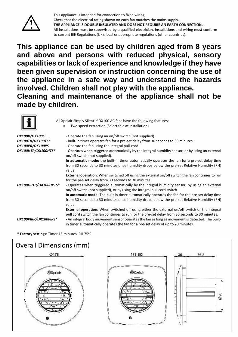
This appliance can be used by children aged from 8 years and above and persons with reduced physical, sensory capabilities or lack of experience and knowledge if they have been given supervision or instruction concerning the use of the appliance in a safe way and understand the hazards involved. Children shall not play with the appliance. Cleaning and maintenance of the appliance shall not be made by children. DX100R/DX100S - Operate the fan using an on/off switch (not supplied). DX100TR/DX100TS* - Built-in timer operates fan for a pre-set delay from 30 seconds to 30 minutes. DX100PR/DX100PS - Operate the fan using the integral pull-cord. DX100HTR/DX100HTS* - Operates when triggered automatically by the integral humidity sensor, or by using an external
on/off switch (not supplied). In automatic mode: the built-in timer automatically operates the fan for a pre-set delay time from 30 seconds to 30 minutes once humidity drops below the pre-set Relative Humidity (RH) value. External operation: When switched off using the external on/off switch the fan continues to run for the pre-set delay from 30 seconds to 30 minutes.
DX100HPTR/DX100HPTS* - Operates when triggered automatically by the integral humidity sensor, by using an external on/off switch (not supplied), or by using the integral pull cord switch.
In automatic mode: The built in timer automatically operates the fan for the pre-set delay time from 30 seconds to 30 minutes once humidity drops below the pre-set Relative Humidity (RH) value.
External operation: When switched off using either the external on/off switch or the integral pull cord switch the fan continues to run for the pre-set delay from 30 seconds to 30 minutes.
DX100PIRR/DX100PIRS* - An integral body movement sensor operates the fan as long as movement is detected. The built-in timer automatically operates the fan for a pre-set delay of up to 20 minutes.
* Factory settings: Timer 15 minutes, RH 75%
Overall Dimensions (mm)
This appliance is intended for connection to fixed wiring. Check that the electrical rating shown on each fan matches the mains supply. THE APPLIANCE IS DOUBLE INSULATED AND DOES NOT REQUIRE AN EARTH CONNECTION. All installations must be supervised by a qualified electrician. Installations and wiring must conform to current IEE Regulations (UK), local or appropriate regulations (other countries).
All Xpelair Simply SilentTM DX100 AC fans have the following features:
Two speed extraction (Selectable at installation)
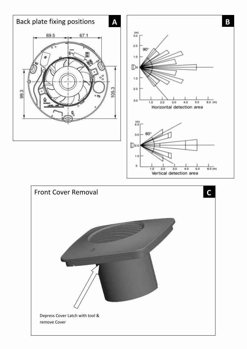
Back plate fixing positions
Front Cover Removal
Depress Cover Latch with tool &
remove Cover
A
C
B
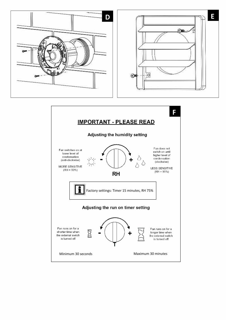
Minimum 30 seconds Maximum 30 minutes
Factory settings: Timer 15 minutes, RH 75%
D E
F
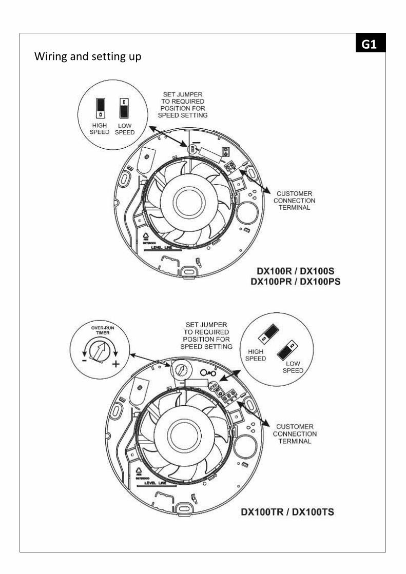
Wiring and setting up G1
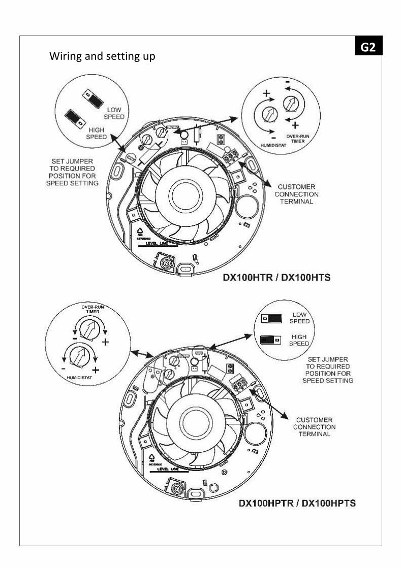
Wiring and setting up G2
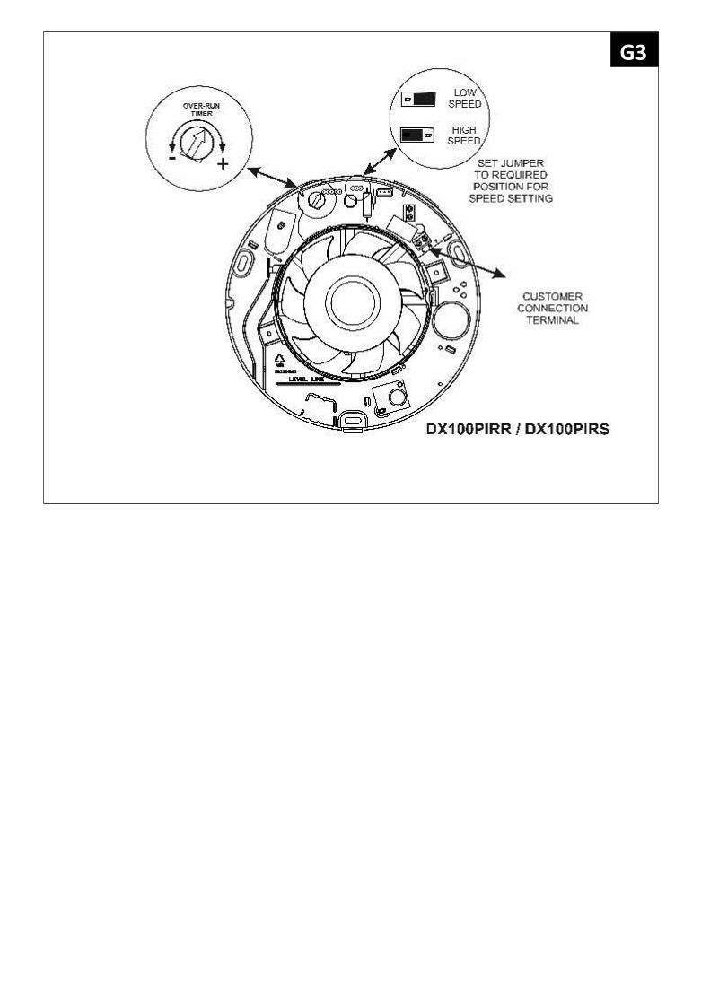
G3
Installation If wall mounting the fan, you will also need:
A 100mm diameter prepared hole.
An appropriate external Wall Grille and Ø100mm wall sleeve duct (supplied). Cut ducting to correct length if required. The wall tube supplied is telescopic and can be extended to 300mm maximum.
If ceiling mounting the fan, you will also need:
A 100mm diameter prepared hole.
A 100mm diameter prepared hole for the external grille, ideally positioned to allow condensation to run away from the first bend in the duct towards the external grille.
Appropriate ancillaries for termination. These items are available from Xpelair: 1. 3m flexible ducting Ref: 89663AA. If the duct passes through a cold space use insulated duct ref: 89847AA. 2. Soffit Grille Ref: 89742AW
If window mounting the fan, you will also need:
SSWIN - Simply Silent Window Kit. Ref: 92996AA
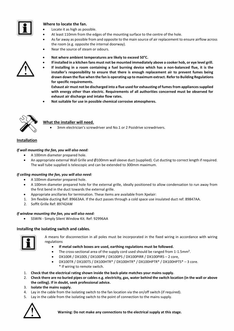
Installing the isolating switch and cables.
1. Check that the electrical rating shown inside the back-plate matches your mains supply. 2. Check there are no buried pipes or cables e.g. electricity, gas, water behind the switch location (in the wall or above
the ceiling). If in doubt, seek professional advice. 3. Isolate the mains supply. 4. Lay in the cable from the isolating switch to the fan location via the on/off switch (if required). 5. Lay in the cable from the isolating switch to the point of connection to the mains supply.
Where to locate the fan. Locate it as high as possible.
At least 110mm from the edges of the mounting surface to the centre of the hole.
As far away as possible from and opposite to the main source of air replacement to ensure airflow across the room (e.g. opposite the internal doorway).
Near the source of steam or odours.
Not where ambient temperatures are likely to exceed 50°C.
If installed in a kitchen fans must not be mounted immediately above a cooker hob, or eye level grill.
If installing in a room containing a fuel burning device which has a non-balanced flue, it is the installer's responsibility to ensure that there is enough replacement air to prevent fumes being drawn down the flue when the fan is operating up to maximum extract. Refer to Building Regulations for specific requirements.
Exhaust air must not be discharged into a flue used for exhausting of fumes from appliances supplied with energy other than electric. Requirements of all authorities concerned must be observed for exhaust air discharge and intake flow rates.
Not suitable for use in possible chemical corrosive atmospheres.
Warning: Do not make any connections to the electrical supply at this stage.
What the installer will need. 3mm electrician’s screwdriver and No.1 or 2 Pozidrive screwdrivers.
A means for disconnection in all poles must be incorporated in the fixed wiring in accordance with wiring regulations
If metal switch boxes are used, earthing regulations must be followed.
The cross-sectional area of the supply cord used should be ranged from 1-1.5mm².
DX100R / DX100S / DX100PR / DX100PS / DX100PIRR / DX100PIRS – 2 core,
DX100TR / DX100TS / DX100HTR* / DX100HTR* / DX100HPTR* / DX100HPTS* – 3 core. * If wiring to remote switch.
C4TS / C4TR / C4HTS / C4HTR. A wall or ceiling On/Off switch (with indicator light) is recommended
6. Install the isolating switch and on/off switch (if required). 7. Make all connections within the isolating switch and the on/off switch (if required).
For Australia Only – DX100R / DX100S / DX100PR / DX100PS / DX100PIRR / DX100PIRS Connection to the supply can be made by a flexible 2-core cable complete with 3 pin plug for insertion into an approved 10A GPO or directly wired through an approved 10A wall mounted surface switch with at least 3mm clearance between contacts. For Australia Only –DX100TR / DX100TS / DX100HTR / DX100HTS / DX100HPTR / DX100HPTS These models are permanently connected to the supply and operation is controlled by a remote switch. They should be directly
wired to the supply through an approved 10A wall mounted surface switch with at least 3mm clearance between contacts.
Preparing the Fan for installation. 1. Remove the front cover by depressing the latch on the underside of the cover and pulling off the front cover from the
bottom (See Figure C). Mark the position of the back-plate
2. Hold the back-plate so that the level line marked on it is orientated horizontally. 3. Carefully insert the fan tube into the wall duct. 4. Mark on the wall the positions of the fixing holes in the back-plate. 5. Remove the back plate from the ducting. 6. Drill screw holes in these positions if necessary, and fit wall plugs and screws as required.
Mount the back-plate.
7. Push the ribbed gasket onto the duct section of the back plate (see Figure D). 8. Push the larger diameter piece of the telescopic wall tube onto the ribbed gasket. Cut the tube to the required size
first if necessary. 9. Feed the mains cable through the cable entry hole in the back plate to the terminals. 10. Insert the fan tube into the wall duct/ceiling as before. 11. Fasten the back-plate to the wall/ceiling using appropriate fasteners supplied. See figure A. 12. If using screws, do not over tighten.
Mount the back draft shutter
13. Peel the backing from the foam strip supplied and attach it around the outside lip on the backdraft shutter. 14. Go outside. Holding open the top and bottom vanes insert the lip into the wall duct. 15. Making sure that the back draft shutter is level, mark the positions of the two fixing holes in the top right hand and
bottom left hand corners. 16. Remove the back draft shutters from the wall duct. 17. Drill screw holes in marked positions and fit the remaining wall plugs. 18. Holding open the top and bottom vanes, refit the back draft shutter and fasten it to the wall using the screws. Do not
overtighten screws. 19. Make sure that the vanes open and shut fully.
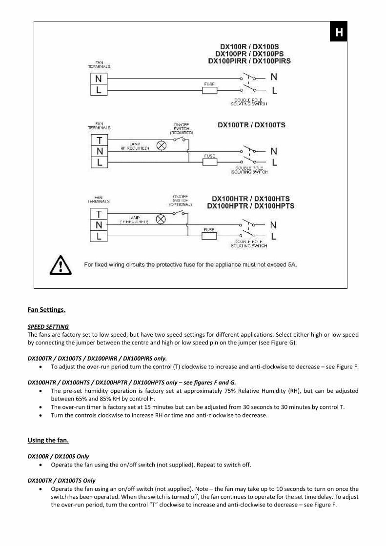
Wire the electrical connections.
20. Make sure the mains supply is isolated. Switch off the mains electrical supply and remove fuses. 21. Feed the cable to the terminal block. Wire the fan as shown in Figure H using the diagram appropriate to the fan
model. 22. Connect the cable from the isolating switch to the electrical supply wiring.
Wet Rooms: On/Off switch must be situated so that it cannot be touched by persons making use of the bath or shower.
If working above ground floor level, safety precautions must be observed.
If installing in a ceiling, appropriate termination ancillaries are required. Follow instructions provided.
Fan Settings. SPEED SETTING The fans are factory set to low speed, but have two speed settings for different applications. Select either high or low speed by connecting the jumper between the centre and high or low speed pin on the jumper (see Figure G). DX100TR / DX100TS / DX100PIRR / DX100PIRS only.
To adjust the over-run period turn the control (T) clockwise to increase and anti-clockwise to decrease – see Figure F. DX100HTR / DX100HTS / DX100HPTR / DX100HPTS only – see figures F and G.
The pre-set humidity operation is factory set at approximately 75% Relative Humidity (RH), but can be adjusted between 65% and 85% RH by control H.
The over-run timer is factory set at 15 minutes but can be adjusted from 30 seconds to 30 minutes by control T.
Turn the controls clockwise to increase RH or time and anti-clockwise to decrease.
Using the fan. DX100R / DX100S Only
Operate the fan using the on/off switch (not supplied). Repeat to switch off. DX100TR / DX100TS Only
Operate the fan using an on/off switch (not supplied). Note – the fan may take up to 10 seconds to turn on once the switch has been operated. When the switch is turned off, the fan continues to operate for the set time delay. To adjust the over-run period, turn the control “T” clockwise to increase and anti-clockwise to decrease – see Figure F.
H
DX100PR / DX100PS Only
Operate the fan by pulling and releasing the cord. Repeat to switch off. DX100HTR / DX100HTS Only.
Automatic mode - The fan automatically adjusts to slow changes in natural humidity levels without operating the fan. If the humidity levels increase at a rate slower than 5% RH in 5 minutes, up to the pre-set humidity level, the fan will not be triggered by humidity. This is to prevent nuisance triggering of the fan. If humidity levels increase quicker than 5% RH in 5 minutes the fan will operate. When relative humidity drops the fan continues to operate for the adjustable time delay.
External operation - Use the external on/off switch. When the fan is switched off, the fan continues to operate for the adjustable time delay then goes into automatic mode.
DX100HPTR / DX100HPTS Only.
Automatic mode - The fan automatically adjusts to slow changes in natural humidity levels without operating the fan. If the humidity levels increase at a rate slower than 5% RH in 5 minutes, up to the pre-set humidity level, the fan will not be triggered by humidity. This is to prevent nuisance triggering of the fan. If humidity levels increase quicker than 5% RH in 5 minutes the fan will operate. When relative humidity drops the fan continues to operate for the adjustable time delay.
External operation - Use the external on/off switch. When the fan is switched off, the fan continues to operate for the adjustable time delay then goes into automatic mode.
Pull Cord operation – Use the integral pull cord switch. When the fan is switched off, the fan continues to operate for the adjustable time delay then goes into automatic mode.
DX100PIRR / DX100PIRS Only.
The sensor detects movement in the room and activates the fan. When movement is sensed, the fan will run for a pre-set over-run period and any further movement sensed will re-start the sequence. This ensures that the room is only ventilated during and immediately after use. When the fan is first installed it will run for the time set by the over-run timer. After this time, if no movement is sensed the fan will go into stand-by mode.
All Fans Re-fit the front cover by hooking in the top first, and then swing the cover down to clip into place.
Cleaning (recommended once a month). 1. Before cleaning, isolate the fan completely from the mains supply. 2. Remove the front cover by depressing the latch on the underside of the cover and pulling off
the front cover from the bottom. 3. To clean the front cover, either wipe it with a damp, lint free cloth or wash it with warm soapy
water. Thoroughly dry the front cover and refit. 4. Do not immerse the fan in water or other liquids to clean any other parts of the fan. 5. Do not use strong detergents, solvents or chemical cleaners 6. Allow fan to dry thoroughly before use. 7. Apart from cleaning, no other maintenance is required.
Disposal
This product should not be disposed of with household waste.
Please recycle where facilities exist.
Check with your local authority for recycling advice.
Guarantee. UK only: We, Redring Xpelair Group Limited, provide a guarantee against faulty parts and manufacture for a period of 2 years from the date of purchase. In the unlikely event of a product breakdown during the guarantee period the product should be returned to the place of purchase or to Redring Xpelair Group Limited. Exclusions:
This guarantee does not cover compensation for the loss of the product or consequential loss of any kind.
Damage or defects to the product arising from incorrect installation or lack of maintenance.
Transportation costs. This guarantee does not affect your statutory rights
Technical advice and service Customers outside UK - see international below. United Kingdom Xpelair have a comprehensive range of services including:
Free technical advice help-desk from Engineers on all aspects of ventilation.
Free design service, quotations and site surveys.
Service and maintenance contracts to suit all requirements. Please ask for details:
By telephone on Techline: +44 (0) 844 372 7766
By fax on Techfax: +44 (0) 844 372 7767
At the address below Head Office, UK Sales Office and Spares Redring Xpelair Group Ltd, Newcombe House, Newcombe Way, Orton Southgate, Peterborough, PE2 6SE England Telephone: +44 (0) 844 372 7761 Fax: +44 (0) 844 372 7762 Sales/Spares Hotline: +44 (0) 844 372 7750 Sales/Spares Faxline: +44 (0) 844 372 7760 http:\\www.xpelair.co.uk International.
Guarantee: Contact your local distributor or Xpelair direct for details.
Technical Advice and Service: Contact your local Xpelair distributor.
Part No: 26097AA (Revision A)