Embed Size (px)
Citation preview

XPR™ 8300 / XPR™ 8380 / XPR™ 8400 Repeater

0
Foreword i
ForewordThis manual is intended for use by experienced technicians familiar with similar types of equipment. Specifically, it contains installation information required for the MOTOTRBO XPR 8300/XPR 8380/XPR 8400 Repeater.
For information related to the service of the XPR 8300/XPR 8380/XPR 8400 Repeater, refer to the list applicable manuals available separately. This list is provided in the Related Publications section on page v.
Product Safety and RF Exposure ComplianceSee Installation Requirements for Compliance with Radio Frequency (RF) Energy Exposure Safety Standards on page ii.
Manual RevisionsChanges which occur after this manual is printed are described in PMRs (Publication Manual Revisions). These PMRs provide complete replacement pages for all added, changed, and deleted items.To obtain PMRs, go to:
http://www.motorola.com/businessonline
Parts OrderingSee Appendix A: Replacement Parts Ordering for information on how to obtain replacement parts. For part numbers, refer to the XPR 8300/XPR 8400 Repeater Basic Service Manual (Motorola Publication part number 6816810H01) and XPR 8380 Repeater Basic Service Manual (Motorola publication part number 68009404001).
Computer Software CopyrightsThe Motorola products described in this manual may include copyrighted Motorola computer programs stored in semiconductor memories or other media. Laws in the United States and other countries preserve for Motorola certain exclusive rights for copyrighted computer programs, including, but not limited to, the exclusive right to copy or reproduce in any form the copyrighted computer program. Accordingly, any copyrighted Motorola computer programs contained in the Motorola products described in this manual may not be copied, reproduced, modified, reverse-engineered, or distributed in any manner without the express written permission of Motorola. Furthermore, the purchase of Motorola products shall not be deemed to grant either directly or by implication, estoppel, or otherwise, any license under the copyrights, patents or patent applications of Motorola, except for the normal non-exclusive license to use that arises by operation of law in the sale of a product.
Document CopyrightsNo duplication or distribution of this document or any portion thereof shall take place without the express written permission of Motorola. No part of this manual may be reproduced, distributed, or transmitted in any form or by any means, electronic or mechanical, for any purpose without the express written permission of Motorola.
DisclaimerThe information in this document is carefully examined, and is believed to be entirely reliable. However, no responsibility is assumed for inaccuracies. Furthermore, Motorola reserves the right to make changes to any products herein to improve readability, function, or design. Motorola does not assume any liability arising out of the applications or use of any product or circuit described herein; nor does it cover any license under its patent rights nor the rights of others.
TrademarksMOTOROLA, the Stylized M logo are registered in the US Patent & Trademark Office. All other product or service names are the property of their respective owners.
© 2006 – 2010 by Motorola, Inc.
ii RF Safety Installation Requirenments
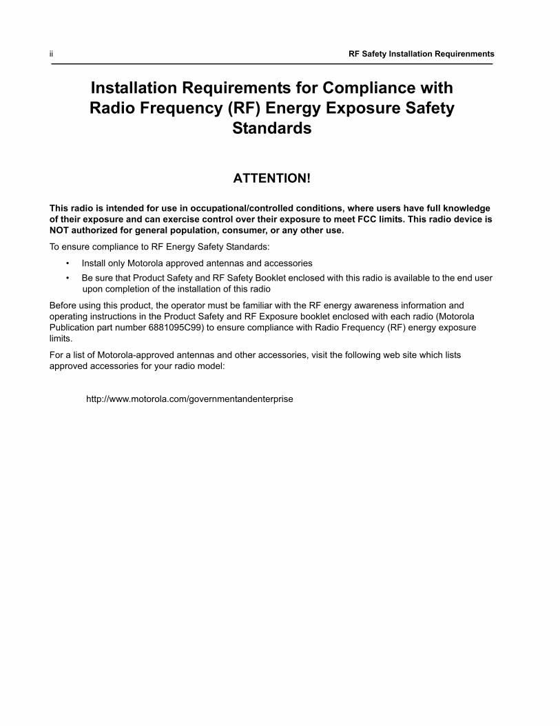
Installation Requirements for Compliance withRadio Frequency (RF) Energy Exposure Safety
Standards
ATTENTION!
This radio is intended for use in occupational/controlled conditions, where users have full knowledge of their exposure and can exercise control over their exposure to meet FCC limits. This radio device is NOT authorized for general population, consumer, or any other use.
To ensure compliance to RF Energy Safety Standards:
• Install only Motorola approved antennas and accessories• Be sure that Product Safety and RF Safety Booklet enclosed with this radio is available to the end user
upon completion of the installation of this radio
Before using this product, the operator must be familiar with the RF energy awareness information and operating instructions in the Product Safety and RF Exposure booklet enclosed with each radio (Motorola Publication part number 6881095C99) to ensure compliance with Radio Frequency (RF) energy exposure limits.
For a list of Motorola-approved antennas and other accessories, visit the following web site which lists approved accessories for your radio model:
http://www.motorola.com/governmentandenterprise
RF Safety Installation Requirenments iii
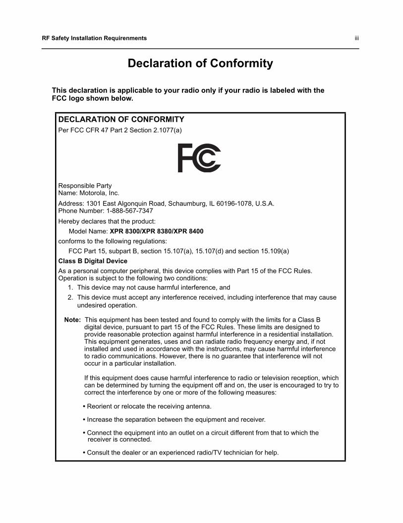
Declaration of Conformity
This declaration is applicable to your radio only if your radio is labeled with the FCC logo shown below.
DECLARATION OF CONFORMITYPer FCC CFR 47 Part 2 Section 2.1077(a)
Responsible Party Name: Motorola, Inc.Address: 1301 East Algonquin Road, Schaumburg, IL 60196-1078, U.S.A.Phone Number: 1-888-567-7347Hereby declares that the product:
Model Name: XPR 8300/XPR 8380/XPR 8400conforms to the following regulations:
FCC Part 15, subpart B, section 15.107(a), 15.107(d) and section 15.109(a)Class B Digital DeviceAs a personal computer peripheral, this device complies with Part 15 of the FCC Rules. Operation is subject to the following two conditions:
1. This device may not cause harmful interference, and 2. This device must accept any interference received, including interference that may cause
undesired operation.
Note: This equipment has been tested and found to comply with the limits for a Class B digital device, pursuant to part 15 of the FCC Rules. These limits are designed to provide reasonable protection against harmful interference in a residential installation. This equipment generates, uses and can radiate radio frequency energy and, if not installed and used in accordance with the instructions, may cause harmful interference to radio communications. However, there is no guarantee that interference will not occur in a particular installation.
If this equipment does cause harmful interference to radio or television reception, which can be determined by turning the equipment off and on, the user is encouraged to try to correct the interference by one or more of the following measures:
• Reorient or relocate the receiving antenna.
• Increase the separation between the equipment and receiver.
• Connect the equipment into an outlet on a circuit different from that to which the receiver is connected.
• Consult the dealer or an experienced radio/TV technician for help.

iv RF Safety Installation Requirenments
Notes
Table of Contents v
Table of Contents
Foreword..........................................................................................................iProduct Safety and RF Exposure Compliance .............................................................................................iManual Revisions .........................................................................................................................................iParts Ordering ..............................................................................................................................................iComputer Software Copyrights ....................................................................................................................iDocument Copyrights ...................................................................................................................................iDisclaimer.....................................................................................................................................................iTrademarks ..................................................................................................................................................i
Installation Requirements for Compliance with Radio Frequency (RF) Energy Exposure Safety Standards.......................ii
Declaration of Conformity ............................................................................iii
List of Figures ..............................................................................................vii
Related Publications....................................................................................vii
Repeater Model Numbering Scheme...........................................................ix
Commercial Warranty ...................................................................................xiLimited Warranty ........................................................................................................................................xi
MOTOROLA COMMUNICATION PRODUCTS................................................................................xiI. What This Warranty Covers and For How Long......................................................................xiII. General Provisions .................................................................................................................xiIII. State Law Rights ................................................................................................................. xiiIV. How to Get Warranty Service .............................................................................................. xiiV. What This Warranty Does Not Cover.................................................................................... xiiVI. Patent and Software Provisions.......................................................................................... xiiiVII. Governing Law................................................................................................................... xiii
Chapter 1 Pre-Installation Considerations ......................................... 1-11.1 Installation Overview...................................................................................................................... 1-11.2 Environmental Conditions at Intended Installation Site ................................................................. 1-1
1.2.1 Operating Temperature Range......................................................................................... 1-11.2.2 Humidity............................................................................................................................ 1-21.2.3 Air Quality ......................................................................................................................... 1-2
1.3 Equipment Ventilation.................................................................................................................... 1-21.4 AC Input Power Requirements ...................................................................................................... 1-2
1.4.1 Circuit Overloading ........................................................................................................... 1-31.5 Equipment Mounting Methods ....................................................................................................... 1-31.6 Site Grounding and Lightning Protection ....................................................................................... 1-3
1.6.1 Electrical Ground .............................................................................................................. 1-31.6.2 RF Ground ........................................................................................................................ 1-31.6.3 Lightning Ground .............................................................................................................. 1-3
vi Table of Contents
Chapter 2 Mechanical Installation....................................................... 2-12.1 Unpacking Equipment.................................................................................................................... 2-12.2 Transferring Equipment from Shipping Container to Rack or Cabinet........................................... 2-1
Chapter 3 Indicators and Connectors................................................. 3-13.1 Front Panel ................................................................................................................................... 3-1
3.1.1 LED Indicator Descriptions ............................................................................................... 3-13.2 Rear Panel .................................................................................................................................... 3-2
3.2.1 Rear Panel Part ................................................................................................................ 3-23.2.2 Rear Accessory Connector ............................................................................................... 3-33.2.3 Ethernet Connector........................................................................................................... 3-3
Chapter 4 Electrical Connections ....................................................... 4-14.1 Power Supply Connections............................................................................................................ 4-1
4.1.1 AC Input Power Connection.............................................................................................. 4-14.1.2 Ground Connection........................................................................................................... 4-24.1.3 Battery Backup Connection .............................................................................................. 4-2
4.2 RF Antenna Connections............................................................................................................... 4-34.2.1 Duplexer Selection............................................................................................................ 4-34.2.2 Antenna Selection............................................................................................................. 4-4
4.3 Frequency Stability ........................................................................................................................ 4-4
Chapter 5 Post-Installation Checklist ................................................. 5-15.1 Applying Power .............................................................................................................................. 5-15.2 Verifying Proper Operation ............................................................................................................ 5-1
5.2.1 Front Panel LEDs.............................................................................................................. 5-15.3 Archiving ........................................................................................................................................ 5-1
5.3.1 Copying the Repeater Codeplug Data to a Computer ...................................................... 5-1
Chapter 6 Accessories ......................................................................... 6-1Antennas..................................................................................................................................................... 1Cables......................................................................................................................................................... 1Miscellaneous Accessories......................................................................................................................... 1
Appendix A Replacement Parts Ordering..............................................A-1A.1 Basic Ordering Information ............................................................................................................A-1A.2 Motorola Online..............................................................................................................................A-1A.3 Mail Orders ....................................................................................................................................A-1A.5 Fax Orders .....................................................................................................................................A-1A.6 Parts Identification .........................................................................................................................A-2A.7 Product Customer Service .............................................................................................................A-2
Appendix B Motorola Service Centers...................................................B-1B.1 Servicing Information .....................................................................................................................B-1B.2 Motorola Service Center ................................................................................................................B-1B.3 Motorola Federal Technical Center................................................................................................B-1B.4 Motorola Canadian Technical Logistics Center .............................................................................B-1
List of Figures vii
List of Figures
Figure 4-1 Locations of Connectors on the Rear Panel of the Repeater ............................................... 4-1Figure 4-2 Making Connections to a Backup Battery ............................................................................. 4-2
Related Publications
MOTOTRBO XPR 8300/XPR 8400 Repeater Basic Service Manual.........................................6816810H01MOTOTRBO XPR 8380 Repeater Basic Service Manual (800/900 MHz Band) ...................... 68009404001MOTOTRBO XPR 8300/XPR 8400 Repeater Detailed Service Manual ....... .... .......................6816811H01MOTOTRBO XPR 8380 Repeater Detailed Service Manual.................................................... 68009403001Motorola Quality Standards Fixed Network Equipment Installation Manual R56 .......................6881089E50Product Safety and RF Exposure booklet ................................................................................. 6881095C99

viii List of Figures
Notes
Repeater Model Numbering Scheme ix
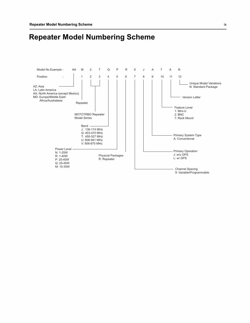
Repeater Model Numbering Scheme
Model No.Example : AA M 2 7 Q P R 9 J A 7 A N Position : 1 2 3 4 5 6 7 8 9 10 11 12
Version Letter
Feature Level 1: Mini-U 2: BNC 7: Rack Mount
Primary System Type A: Conventional
Primary Operation J: w/o GPS L: w/ GPS
Channel Spacing 9: Variable/Programmable
Power LevelN: 1-25WR: 1-40WP: 25-40WQ: 25-45WM: 10-35W
MOTOTRBO Repeater Model Series
BandJ : 136-174 MHzQ: 403-470 MHzT: 450-527 MHzU: 806-941 MHzV: 806-870 MHz
Physical Packages R: Repeater
Repeater
AZ: Asia LA: Latin America AA: North America (except Mexico) MD: Europe/Middle East/ Africa/Australasia
Unique Model Variations N: Standard Package

x Repeater Model Numbering Scheme
Notes
Commercial Warranty xi
Commercial Warranty
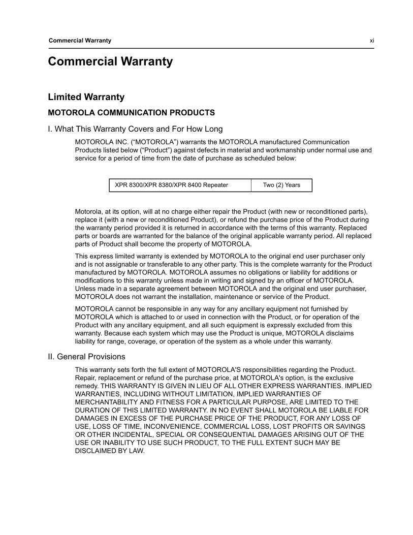
Limited WarrantyMOTOROLA COMMUNICATION PRODUCTS
I. What This Warranty Covers and For How LongMOTOROLA INC. (“MOTOROLA”) warrants the MOTOROLA manufactured Communication Products listed below (“Product”) against defects in material and workmanship under normal use and service for a period of time from the date of purchase as scheduled below:
Motorola, at its option, will at no charge either repair the Product (with new or reconditioned parts), replace it (with a new or reconditioned Product), or refund the purchase price of the Product during the warranty period provided it is returned in accordance with the terms of this warranty. Replaced parts or boards are warranted for the balance of the original applicable warranty period. All replaced parts of Product shall become the property of MOTOROLA.
This express limited warranty is extended by MOTOROLA to the original end user purchaser only and is not assignable or transferable to any other party. This is the complete warranty for the Product manufactured by MOTOROLA. MOTOROLA assumes no obligations or liability for additions or modifications to this warranty unless made in writing and signed by an officer of MOTOROLA. Unless made in a separate agreement between MOTOROLA and the original end user purchaser, MOTOROLA does not warrant the installation, maintenance or service of the Product.
MOTOROLA cannot be responsible in any way for any ancillary equipment not furnished by MOTOROLA which is attached to or used in connection with the Product, or for operation of the Product with any ancillary equipment, and all such equipment is expressly excluded from this warranty. Because each system which may use the Product is unique, MOTOROLA disclaims liability for range, coverage, or operation of the system as a whole under this warranty.
II. General ProvisionsThis warranty sets forth the full extent of MOTOROLA'S responsibilities regarding the Product. Repair, replacement or refund of the purchase price, at MOTOROLA's option, is the exclusive remedy. THIS WARRANTY IS GIVEN IN LIEU OF ALL OTHER EXPRESS WARRANTIES. IMPLIED WARRANTIES, INCLUDING WITHOUT LIMITATION, IMPLIED WARRANTIES OF MERCHANTABILITY AND FITNESS FOR A PARTICULAR PURPOSE, ARE LIMITED TO THE DURATION OF THIS LIMITED WARRANTY. IN NO EVENT SHALL MOTOROLA BE LIABLE FOR DAMAGES IN EXCESS OF THE PURCHASE PRICE OF THE PRODUCT, FOR ANY LOSS OF USE, LOSS OF TIME, INCONVENIENCE, COMMERCIAL LOSS, LOST PROFITS OR SAVINGS OR OTHER INCIDENTAL, SPECIAL OR CONSEQUENTIAL DAMAGES ARISING OUT OF THE USE OR INABILITY TO USE SUCH PRODUCT, TO THE FULL EXTENT SUCH MAY BE DISCLAIMED BY LAW.
XPR 8300/XPR 8380/XPR 8400 Repeater Two (2) Years
xii Commercial Warranty
III. State Law Rights SOME STATES DO NOT ALLOW THE EXCLUSION OR LIMITATION OF INCIDENTAL OR CONSEQUENTIAL DAMAGES OR LIMITATION ON HOW LONG AN IMPLIED WARRANTY LASTS, SO THE ABOVE LIMITATION OR EXCLUSIONS MAY NOT APPLY.
This warranty gives specific legal rights, and there may be other rights which may vary from state to state.
IV. How to Get Warranty ServiceYou must provide proof of purchase (bearing the date of purchase and Product item serial number) in order to receive warranty service and, also, deliver or send the Product item, transportation and insurance prepaid, to an authorized warranty service location. Warranty service will be provided by Motorola through one of its authorized warranty service locations. If you first contact the company which sold you the Product, it can facilitate your obtaining warranty service. You can also call Motorola at 1-888-567-7347 US/Canada.
V. What This Warranty Does Not CoverA. Defects or damage resulting from use of the Product in other than its normal and customary
manner.
B. Defects or damage from misuse, accident, water, or neglect.
C. Defects or damage from improper testing, operation, maintenance, installation, alteration, modification, or adjustment.
D. Breakage or damage to antennas unless caused directly by defects in material workmanship.
E. A Product subjected to unauthorized Product modifications, disassemblies or repairs (including, without limitation, the addition to the Product of non-Motorola supplied equipment) which adversely affect performance of the Product or interfere with Motorola's normal warranty inspection and testing of the Product to verify any warranty claim.
F. Product which has had the serial number removed or made illegible.
G. Rechargeable batteries if:
- any of the seals on the battery enclosure of cells are broken or show evidence of tampering.
- the damage or defect is caused by charging or using the battery in equipment or service other than the Product for which it is specified.
H. Freight costs to the repair depot.
I. A Product which, due to illegal or unauthorized alteration of the software/firmware in the Product, does not function in accordance with MOTOROLA’s published specifications or the FCC type acceptance labeling in effect for the Product at the time the Product was initially distributed from MOTOROLA.
J. Scratches or other cosmetic damage to Product surfaces that does not affect the operation of the Product.
K. Normal and customary wear and tear.
Commercial Warranty xiii
VI. Patent and Software ProvisionsMOTOROLA will defend, at its own expense, any suit brought against the end user purchaser to the extent that it is based on a claim that the Product or parts infringe a United States patent, and MOTOROLA will pay those costs and damages finally awarded against the end user purchaser in any such suit which are attributable to any such claim, but such defense and payments are conditioned on the following:
A. that MOTOROLA will be notified promptly in writing by such purchaser of any notice of such claim;
B. that MOTOROLA will have sole control of the defense of such suit and all negotiations for its settlement or compromise; and
C. should the Product or parts become, or in MOTOROLA's opinion be likely to become, the subject of a claim of infringement of a United States patent, that such purchaser will permit MOTOROLA, at its option and expense, either to procure for such purchaser the right to continue using the Product or parts or to replace or modify the same so that it becomes noninfringing or to grant such purchaser a credit for the Product or parts as depreciated and accept its return. The depreciation will be an equal amount per year over the lifetime of the Product or parts as established by MOTOROLA.
MOTOROLA will have no liability with respect to any claim of patent infringement which is based upon the combination of the Product or parts furnished hereunder with software, apparatus or devices not furnished by MOTOROLA, nor will MOTOROLA have any liability for the use of ancillary equipment or software not furnished by MOTOROLA which is attached to or used in connection with the Product. The foregoing states the entire liability of MOTOROLA with respect to infringement of patents by the Product or any parts thereof.
Laws in the United States and other countries preserve for MOTOROLA certain exclusive rights for copyrighted MOTOROLA software such as the exclusive rights to reproduce in copies and distribute copies of such Motorola software. MOTOROLA software may be used in only the Product in which the software was originally embodied and such software in such Product may not be replaced, copied, distributed, modified in any way, or used to produce any derivative thereof. No other use including, without limitation, alteration, modification, reproduction, distribution, or reverse engineering of such MOTOROLA software or exercise of rights in such MOTOROLA software is permitted. No license is granted by implication, estoppel or otherwise under MOTOROLA patent rights or copyrights.
VII. Governing LawThis Warranty is governed by the laws of the State of Illinois, USA.

xiv Commercial Warranty
Notes
Chapter 1 Pre-Installation Considerations Proper installation ensures the best possible performance and reliability of the MOTOTRBO Repeater. Pre-installation planning is required. This includes considering the mounting location of the repeater in relation to input power and antennas. Also consider the site environmental conditions, the particular mounting method (several available), and required tools and equipment.
If this is the first time this type of equipment is being installed, it is highly recommended that the user read:
• this entire installation section before beginning the actual installation, and• the Motorola Quality Standard Fixed Network Equipment Installation manual, R56
(6881089E50), specifically refer to the information on ground connection for lightning protection.
1.1 Installation OverviewThe following information is an overview for installing the MOTOTRBO Repeater and ancillary equipment.
• Plan the installation, paying particular attention to environmental conditions at the site, ventilation requirements, and grounding and lightning protection.
• Unpack and inspect the equipment.• Mechanical install the equipment at the site.• Make necessary electrical and cabling connections, including the following:
- AC input cabling- Coaxial cables to transmit and receive antennas
• Perform a post-installation function checkout test of the equipment to verify proper installation.• Proceed to customize the repeater parameters per customer specifications (e.g. operating
frequency, PL, codes, color code, etc.).
1.2 Environmental Conditions at Intended Installation SiteThe repeater may be installed in any location suitable for electronic communications equipment, provided that the environmental conditions do not exceed the equipment specifications for temperature, humidity, and air quality.
NOTE: The XPR 8300 VHF and UHF Repeaters have been manufactured with a power-saving main fan, since July, 2008. The fan powers ON temporarily as a self-check after the user initially turns the repeater power ON. If the repeater’s internal ambient temperature remains below 30 °C (86 °F), the fan does not operate. It powers ON and remains operational only after the repeater’s internal ambient temperature rises above 30 °C (86 °F), and its speed increases as the temperatures rises. At 50 °C (122 °F), the fan runs at full speed. For XPR 8380 800 and 800/900 MHz repeaters, in an effort to provide optimum performance and power efficiency, the repeater main fan is set to operate at a temperature of 10 °C (50 °F) or higher. The fan speed will be held constant from 10 °C to 30 °C. Between 30 °C (86 °F) and 45 °C (113 °F), the fan will increase in speed and reach full speed at 46 °C (115 °F). Please note that the XPR 8400 32 MB repeaters manufactured after October 2010 will have a default setting of full speed for the main fan. However, the dealer will have an option to change the setting to variable speed through an on-board switch on the connector board assembly. The variable speed behavior is as follows: The fan will idle low and be held constant from 10 °C to 30 °C. Between 30 °C and 45 °C, the fan will increase in speed and reach full speed at 46 °C.
1.2.1 Operating Temperature Range-30 °C (-22 °F) to +60 °C (+140 °F)
1-2 Pre-Installation Considerations Equipment Ventilation
This is the temperature measured in close proximity to the repeater. For example, if the repeater is mounted in a cabinet, the temperature within the cabinet is measured.
1.2.2 HumidityHumidity conditions should not exceed 95% relative humidity at 50 °C (122 °F).
1.2.3 Air Quality For equipment operating in an area which is environmentally controlled and with the repeater(s) rack mounted, the airborne particle level must not exceed 25 µg/m³.
For equipment operating in an area which is not environmentally controlled and with the repeater(s) cabinet mounted, airborne particle level must not exceed 90 µg/m³.
1.3 Equipment VentilationThe repeater is equipped with a cooling fan that is used to provide forced convection cooling. When planning the installation, observe the following ventilation guidelines:
• Customer-supplied cabinets must be equipped with ventilation slots or openings in the front (for air entry) and back or side panels (for air to exit). If several repeaters are installed in a single cabinet, ensure ventilation openings surrounding each repeater allow for adequate cooling.
• All cabinets must have a least 15 cm (6 inches) of open space between the air vents and any wall or other objects.
• When multiple cabinets (each equipped with several repeaters) are installed in an enclosed area, ensure appropriate ventilation and consider air conditioning or other climate control equipment to satisfy the temperature requirements stated under “Operating Temperature Range” on page 1-1.
1.4 AC Input Power RequirementsThe repeater is equipped with a switching power supply, and this assembly operates from 100 – 240 VAC at 47 – 63 Hz AC input power. A standard 3-prong line cord is supplied to connect the power supply to the AC source.
It is recommended that a standard 3-wire grounded electrical outlet be used as the AC source.
The outlet must be connected to an AC source capable of supplying a maximum of 280 W. For a nominal 110/120 VAC input, the AC source must supply 5 A and should be protected by circuit breaker rated at 15 A. For a nominal 220/240 VAC input, the AC source must supply 3 A and should be protected by a circuit breaker rated at 10 A.
If the repeater is to be installed in an environment which is usually dusty, dirty, or does not meet the air quality requirements, then the air used to cool the repeater modules must be treated using appropriate filtering devices. Dust or dirt accumulating on the internal circuit boards and modules is not easily removed, and can cause such malfunctions as overheating and intermittent electrical connections.
The equipment must be installed near an easily-accessible AC source.
!C a u t i o n
!C a u t i o n
Pre-Installation Considerations Equipment Mounting Methods 1-3
1.4.1 Circuit OverloadingConsideration should be given to the effects of overloading on overcurrent protection devices and supply wiring. Appropriate consideration of equipment ratings should be used when addressing this concern.
1.5 Equipment Mounting MethodsThe MOTOTRBO Repeater may be mounted in a rack, bracket or cabinet (available as accessories).
1.6 Site Grounding and Lightning Protection
One of the most important considerations when designing a communications site is the ground and lightning protection system. While proper grounding techniques and lightning protection are closely related, the general category of site grounding may be divided into the following section.
1.6.1 Electrical GroundGround wires carrying electrical current from circuitry or equipment at the site is included in the category of electrical ground. Examples include the AC or DC electrical power used to source equipment located at the site, and wires or cables connected to alarms or sensors located at the site.
1.6.2 RF GroundThis type of ground is related to the bypassing of unwanted radio frequency energy to earth ground. An example of RF grounding is the use of shielding to prevent or at least minimize the leakage of unwanted RF energy from communications equipment and cables.
1.6.3 Lightning Ground Providing adequate lightning protection is critical to a safe reliable communications site. RF transmission cables, and AC and DC power lines must all be protected to prevent lightning energy from entering the site.
Comprehensive coverage of site grounding techniques and lightning protection is not within the scope of this instruction manual, but there are several excellent industry sources for rules and guidelines on grounding and lightning protection at communications sites.
NOTE: Motorola recommends the following reference source: Motorola Quality Standards Fixed Network Equipment Installation Manual R56……………………...……………......................................6881089E50
1.6.4 Equipment GroundingThe repeater is equipped with a ground screw located on the rear of the repeater power supply module. This screw is used to connect the repeater to the site grounding. All antenna cables, and AC and DC power cabling, should be properly grounded and lightning protected by following the rules and guidelines provided in the above reference. Failure to provide proper lightning protection may result in permanent damage to the radio equipment.
Proper site grounding and lightning protection are vitally important considerations. Failure to provide proper lightning protection may result in permanent damage to the radio equipment.
!W A R N I N G
!

1-4 Pre-Installation Considerations
Notes
Chapter 2 Mechanical Installation
This section describes the procedures to unpack and mechanically install the MOTOTRBO Repeater. A variety of mounting methods are possible depending on which type of cabinet or rack (if any) has been selected to house the repeater(s).
2.1 Unpacking EquipmentThe following items are packed together in the box:
• MOTOTRBO Repeater• AC Line Cord• MOTOTRBO Repeater Installation Guide• Product Safety and RF Exposure Booklet
2.2 Transferring Equipment from Shipping Container to Rack or CabinetThe repeater is shipped in a box. Upon delivery, the equipment must be removed from the container and transferred to a rack or cabinet.
NOTE: Customer-supplied cabinets and racks must have mounting rail and hole spacing compatible with EIA Universal 48.3 cm (19 inches) specifications. Cabinets must provide adequate ventilation (see “Environmental Conditions at Intended Installation Site” on page 1-1) and must meet the following minimum criteria:
- 41.3 cm (16.25 inches) deep- 48.3 cm (19 inches) wide- 13.4 cm (5.25 inches) high- Two mounting rails 5 cm (2 inches) from the front of the cabinet with front mounting holes
5.7 cm (2.25 inches) apart (center to center).
Contact Motorola Technical Support for specific question(s) regarding mounting equipment in customer-supplied cabinets.
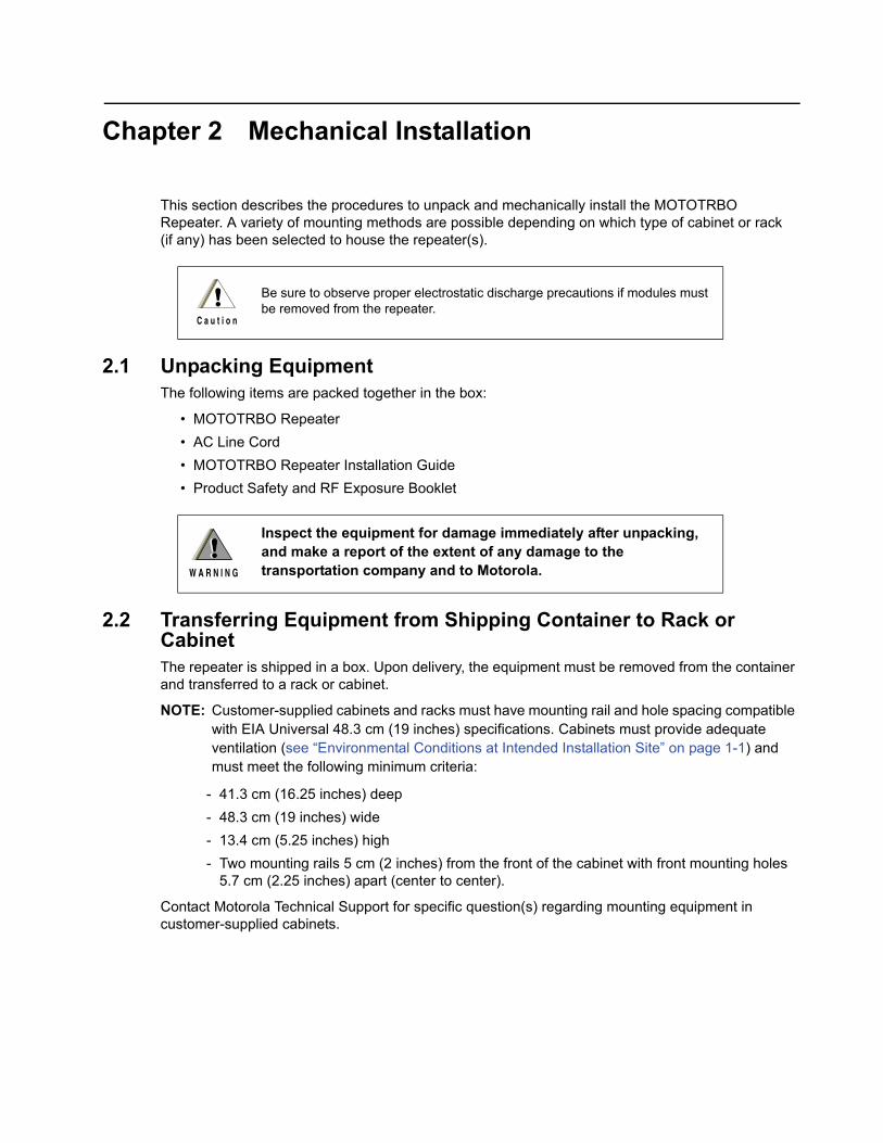
Be sure to observe proper electrostatic discharge precautions if modules must be removed from the repeater.
Inspect the equipment for damage immediately after unpacking, and make a report of the extent of any damage to the transportation company and to Motorola.
!C a u t i o n
!W A R N I N G
!

2-2 Mechanical Installation
Notes
Chapter 3 Indicators and Connectors
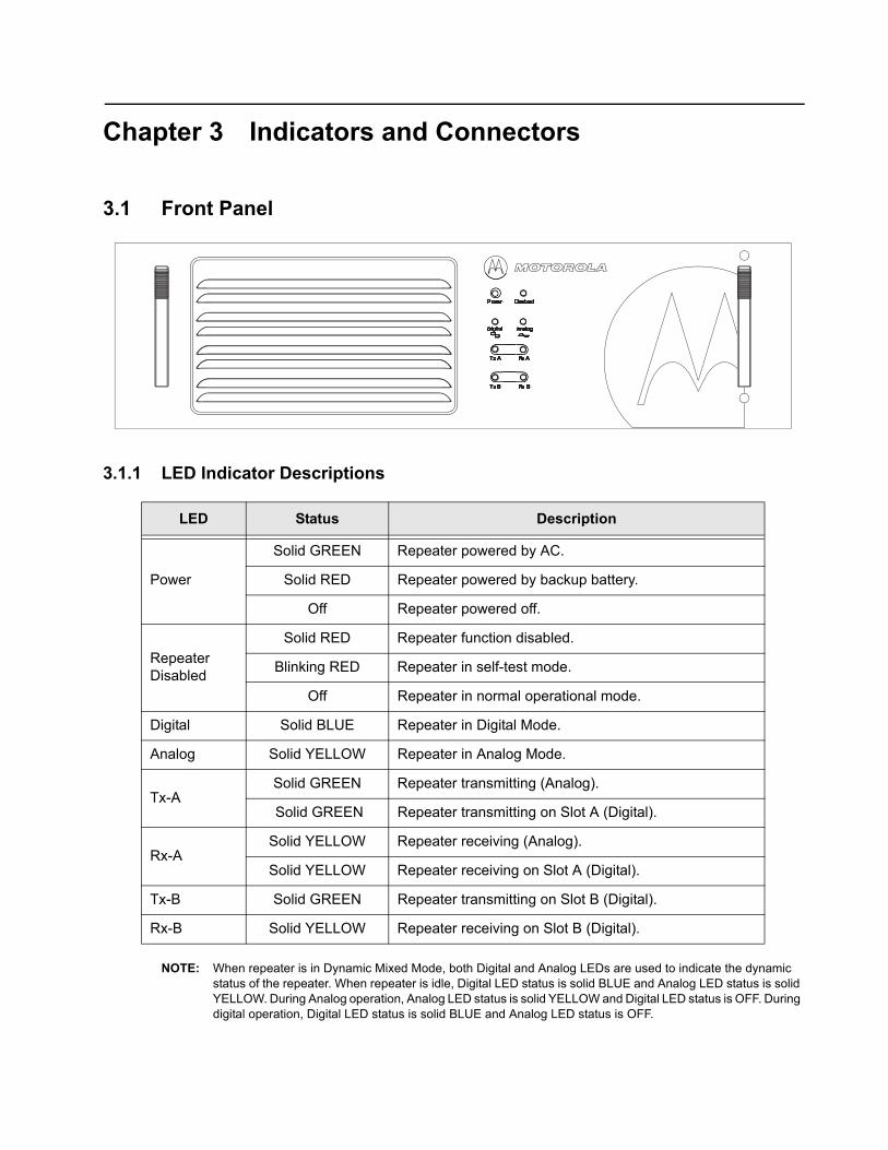
3.1 Front Panel
3.1.1 LED Indicator Descriptions
NOTE: When repeater is in Dynamic Mixed Mode, both Digital and Analog LEDs are used to indicate the dynamic status of the repeater. When repeater is idle, Digital LED status is solid BLUE and Analog LED status is solid YELLOW. During Analog operation, Analog LED status is solid YELLOW and Digital LED status is OFF. During digital operation, Digital LED status is solid BLUE and Analog LED status is OFF.
LED Status Description
Power
Solid GREEN Repeater powered by AC.
Solid RED Repeater powered by backup battery.
Off Repeater powered off.
Repeater Disabled
Solid RED Repeater function disabled.
Blinking RED Repeater in self-test mode.
Off Repeater in normal operational mode.
Digital Solid BLUE Repeater in Digital Mode.
Analog Solid YELLOW Repeater in Analog Mode.
Tx-ASolid GREEN Repeater transmitting (Analog).
Solid GREEN Repeater transmitting on Slot A (Digital).
Rx-ASolid YELLOW Repeater receiving (Analog).
Solid YELLOW Repeater receiving on Slot A (Digital).
Tx-B Solid GREEN Repeater transmitting on Slot B (Digital).
Rx-B Solid YELLOW Repeater receiving on Slot B (Digital).
3-2 Indicators and Connectors Rear Panel
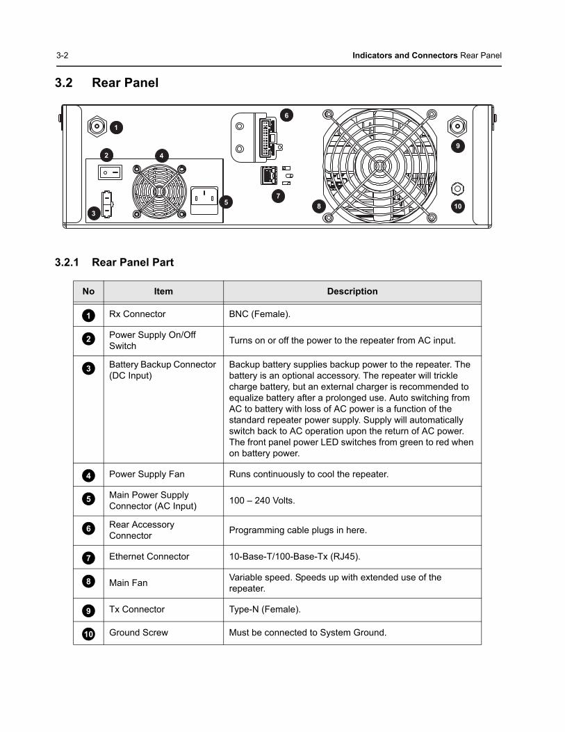
3.2 Rear Panel
3.2.1 Rear Panel Part
No Item Description
Rx Connector BNC (Female).
Power Supply On/Off Switch Turns on or off the power to the repeater from AC input.
Battery Backup Connector (DC Input)
Backup battery supplies backup power to the repeater. The battery is an optional accessory. The repeater will trickle charge battery, but an external charger is recommended to equalize battery after a prolonged use. Auto switching from AC to battery with loss of AC power is a function of the standard repeater power supply. Supply will automatically switch back to AC operation upon the return of AC power. The front panel power LED switches from green to red when on battery power.
Power Supply Fan Runs continuously to cool the repeater.
Main Power Supply Connector (AC Input) 100 – 240 Volts.
Rear Accessory Connector Programming cable plugs in here.
Ethernet Connector 10-Base-T/100-Base-Tx (RJ45).
Main Fan Variable speed. Speeds up with extended use of the repeater.
Tx Connector Type-N (Female).
Ground Screw Must be connected to System Ground.
1
3
2 4
5
6
78
9
10
1
2
3
4
5
6
7
8
9
10
Indicators and Connectors Rear Panel 3-3
3.2.2 Rear Accessory ConnectorThe rear accessory connector is located above the ethernet connector. Most of the Motorola-approved accessories are supplied with female terminals crimped to a 20-gauge wire specifically designed to fit the housing of the rear accessory connector.
Insert the female terminal into the accessory connector housing in the appropriate locations. The accessory connector housing is provided together with the accessory. Connect the accessory connector housing to the rear accessory connector on the back of the repeater. Do not use other generic terminals in the housing. Generic terminals can cause electrical intermittences and may cause damage to the housing.
3.2.3 Ethernet ConnectorThe Ethernet connector supports both 10-Base T and 100-Base-Tx connections. There are two integrated LEDs (only supported on XPR 8380 and XPR 8400) in the connector:
Status Description
Green LED Indicates 100 Mbits speed when lit, and 10 Mbits speed when OFF.
Yellow LED Indicates a valid link when lit solid, and transmit/receive activity when blinking.
3-4 Indicators and Connectors Rear Panel
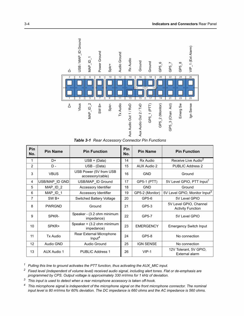
1 Pulling this line to ground activates the PTT function, thus activating the AUX_MIC input.2 Fixed level (independent of volume level) received audio signal, including alert tones. Flat or de-emphasis are
programmed by CPS. Output voltage is approximately 330 mVrms for 1 kHz of deviation.3 This input is used to detect when a rear microphone accessory is taken off-hook.4 This microphone signal is independent of the microphone signal on the front microphone connector. The nominal
input level is 80 mVrms for 60% deviation. The DC impedance is 660 ohms and the AC impedance is 560 ohms.
Table 3-1 Rear Accessory Connector Pin Functions
Pin No. Pin Name Pin Function Pin
No. Pin Name Pin Function
1 D+ USB + (Data) 14 Rx Audio Receive Live Audio2
2 D - USB - (Data) 15 AUX Audio 2 PUBLIC Address 2
3 VBUS USB Power (5V from USB accessory/cable) 16 GND Ground
4 USB/MAP_ID GND USB/MAP_ID Ground 17 GP5-1 (PTT) 5V Level GPIO, PTT Input1
5 MAP_ID_2 Accessory Identifier 18 GND Ground6 MAP_ID_1 Accessory Identifier 19 GP5-2 (Monitor) 5V Level GPIO, Monitor Input3
7 SW B+ Switched Battery Voltage 20 GP5-6 5V Level GPIO
8 PWRGND Ground 21 GP5-3 5V Level GPIO, Channel Activity Function
9 SPKR- Speaker - (3.2 ohm minimum impedance) 22 GP5-7 5V Level GPIO
10 SPKR+ Speaker + (3.2 ohm minimum impedance) 23 EMERGENCY Emergency Switch Input
11 Tx Audio Rear External Microphone Input4 24 GP5-8 No connection
12 Audio GND Audio Ground 25 IGN SENSE No connection
13 AUX Audio 1 PUBLIC Address 1 26 VIP-1 12V Tolerant, 5V GPIO, External alarm
1
2
3
4
5
6
7
8
9
10
11
12
13
14
15
16
17
18
19
20
21
22
23
24
25
26
D+
Vbu
s
SW
B+
Spk
r-
Tx A
udio
Aux
Aud
io O
ut 1
/ R
xD
Aux
Aud
io O
ut 2
/ Tx
D
GP
5_1
(PTT
)
GP
5_2
(Mon
itor)
GP
5_3
(Cha
n A
ct)
Em
erg
Sw
Ign
Sen
se
D-
US
B /
MA
P_I
D G
roun
d
MA
P_I
D_1
Pow
er G
roun
d
Spk
r+
Aud
io G
roun
d
Rx
Aud
io
Gro
und
Gro
und
GP
5_6
GP
5_7
GP
5_8
VIP
_1 (E
xt A
larm
)
MA
P_I
D_2
Chapter 4 Electrical Connections
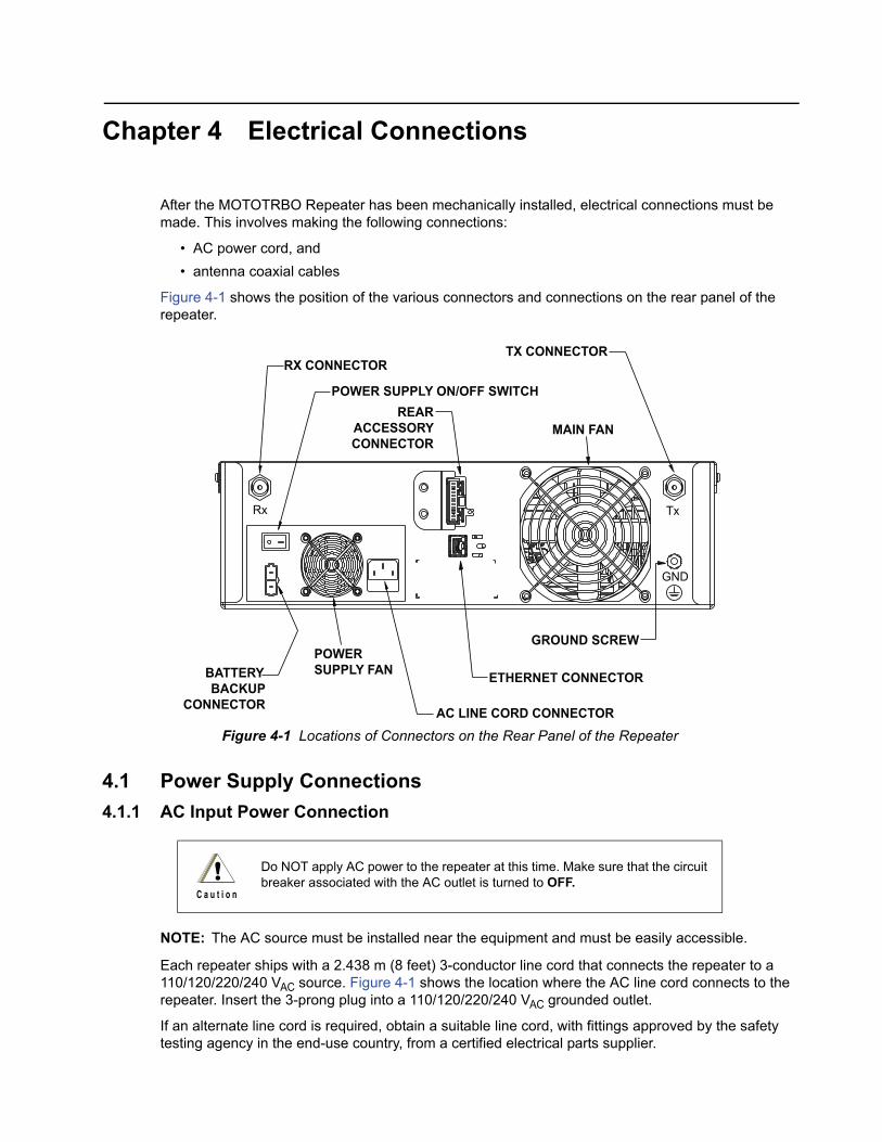
After the MOTOTRBO Repeater has been mechanically installed, electrical connections must be made. This involves making the following connections:
• AC power cord, and• antenna coaxial cables
Figure 4-1 shows the position of the various connectors and connections on the rear panel of the repeater.
Figure 4-1 Locations of Connectors on the Rear Panel of the Repeater
4.1 Power Supply Connections 4.1.1 AC Input Power Connection
NOTE: The AC source must be installed near the equipment and must be easily accessible.
Each repeater ships with a 2.438 m (8 feet) 3-conductor line cord that connects the repeater to a 110/120/220/240 VAC source. Figure 4-1 shows the location where the AC line cord connects to the repeater. Insert the 3-prong plug into a 110/120/220/240 VAC grounded outlet.
If an alternate line cord is required, obtain a suitable line cord, with fittings approved by the safety testing agency in the end-use country, from a certified electrical parts supplier.
Do NOT apply AC power to the repeater at this time. Make sure that the circuit breaker associated with the AC outlet is turned to OFF.
Tx Rx
GND
POWER SUPPLY FAN BATTERY
BACKUP CONNECTOR AC LINE CORD CONNECTOR
ETHERNET CONNECTOR
GROUND SCREW
TX CONNECTOR RX CONNECTOR
POWER SUPPLY ON/OFF SWITCH REAR
ACCESSORYCONNECTOR
MAIN FAN
!C a u t i o n
4-2 Electrical Connections Power Supply Connections
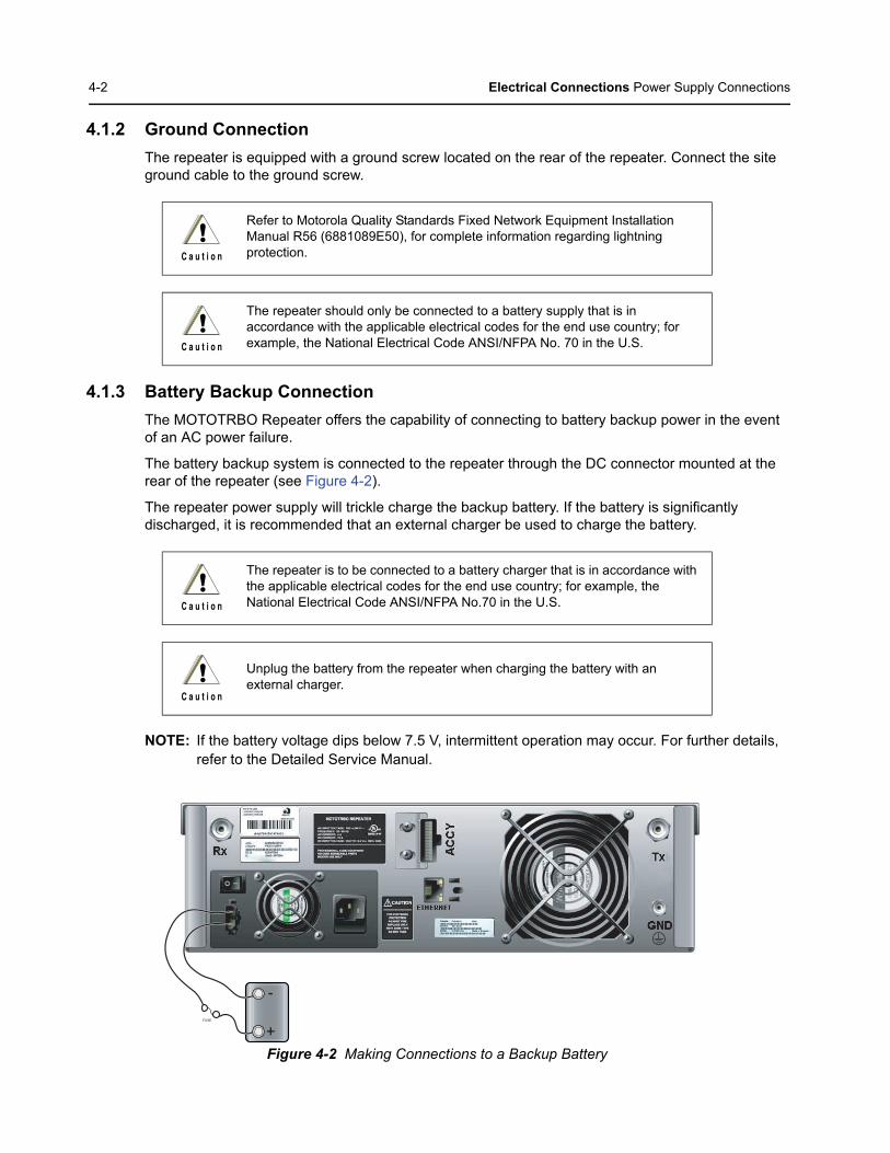
4.1.2 Ground ConnectionThe repeater is equipped with a ground screw located on the rear of the repeater. Connect the site ground cable to the ground screw.
4.1.3 Battery Backup ConnectionThe MOTOTRBO Repeater offers the capability of connecting to battery backup power in the event of an AC power failure.
The battery backup system is connected to the repeater through the DC connector mounted at the rear of the repeater (see Figure 4-2).
The repeater power supply will trickle charge the backup battery. If the battery is significantly discharged, it is recommended that an external charger be used to charge the battery.
NOTE: If the battery voltage dips below 7.5 V, intermittent operation may occur. For further details, refer to the Detailed Service Manual.
Figure 4-2 Making Connections to a Backup Battery
Refer to Motorola Quality Standards Fixed Network Equipment Installation Manual R56 (6881089E50), for complete information regarding lightning protection.
The repeater should only be connected to a battery supply that is in accordance with the applicable electrical codes for the end use country; for example, the National Electrical Code ANSI/NFPA No. 70 in the U.S.
The repeater is to be connected to a battery charger that is in accordance with the applicable electrical codes for the end use country; for example, the National Electrical Code ANSI/NFPA No.70 in the U.S.
Unplug the battery from the repeater when charging the battery with an external charger.
!C a u t i o n
!C a u t i o n
!C a u t i o n
!C a u t i o n
+
-
FUSE
Electrical Connections RF Antenna Connections 4-3
4.2 RF Antenna ConnectionsThe transmit and receive antenna RF connection are made using two separate connectors. Coaxial cables from the receive and transmit antenna must be connected to the Type-N (Tx) and BNC (Rx) connectors. The position of these connectors is shown in Figure 4-1. For repeater use, the antennas need adequate isolation between them, or if one antenna is used, the duplexer needs to have adequate isolation between the Tx and Rx ports. The isolation requirements are unique to each band and are shown in the table below:
If the duplexer isolation is not adequate, a preselector may also be used. See “Accessories” on page 6-1 for a list of available duplexers and preselectors.
4.2.1 Duplexer SelectionThe selection of a duplexer is critical to system performance. The use of a notch (band reject) duplexer is possible in some systems that are not located at high RF density sites. See “Accessories” on page 6-1 for a list of available duplexers. The duplexer must be able to handle at least 50 W continuously. For the best system performance, the insertion loss should be less than 2 dB. If the repeater is used in higher RF density sites, the use of a pass-notch duplexer is recommended.
Frequency Band Bandwidth Isolation
UHF 1 403 – 470 MHz 75 dB
UHF 2 450 – 512 MHz 85 dB
VHF 136 – 174 MHz 85 dB
800 806 – 870 MHz 85 dB
800/900 806 – 941 MHz 85 dB
XPR 8400 32 MB 806 – 941 MHz 85 dB
The repeater can key up at any time due to input from a subscriber unit or a CW ID. Please ensure that all power is switched off before disconnecting the transmit antenna.
!C a u t i o n
4-4 Electrical Connections Frequency Stability
4.2.2 Antenna SelectionThe selection of the antenna is critical to system performance. The selected antenna must be 50 ohm impedance and capable of at least 50 watts. Gain antennas may be used to increase system coverage. Please take note of licensing restrictions when selecting gain antennas. Some services or regions may have antenna gain or system ERP limitations.
The antenna must be connected to the duplexer with a high grade 50 ohm transmission line (hardline). The line must have connectors to match the connectors on the duplexer and antenna. For proper antenna installation, please also consult the Motorola Quality Standards Fixed Network Equipment Installation Manual R56 (6881089E50).
4.3 Frequency Stability The 800/900 MHz repeaters are equipped with a high-stability, 0.1 ppm OCXO (oven controlled crystal oscillator). This oscillator requires approximately 10 minutes of warm-up time (worst case scenario) to meet the frequency stability requirements of the 900 MHz band.
It is important that all antenna cables are grounded at the point they enter the building.
The antenna design is the customer's responsibility. All aspects of the antenna design must comply with the relevant local regulations.
!C a u t i o n
!C a u t i o n
Chapter 5 Post-Installation Checklist
After the MOTOTRBO Repeater has been mechanically installed and all electrical connections have been made, power may now be applied and the repeater checked for proper operation.
5.1 Applying PowerBefore applying power to the repeater, make sure all boards are securely seated in the appropriate connectors on the backplane and that all RF cables are securely connected.
Turn ON the circuit breaker controlling the AC outlet that is supplying power to the repeater Power Supply Module.
5.2 Verifying Proper OperationOperation of the repeater can be verified by:
• observing the state of the 8 LEDs located on the front panel, and• exercising radio operation.
5.2.1 Front Panel LEDsAfter turning ON the repeater power (or after a repeater reset), the 8 LEDs on the repeater front panel:
• Light for about one second to indicate that they are functional, then• Go off for one second, then• Indicate the operational status of the repeater.
5.3 Archiving5.3.1 Copying the Repeater Codeplug Data to a Computer
Backup the repeater's codeplug data by using the Customer Programming Software (CPS) on a computer.
Some repeater components can become extremely hot during operation. Turn off all power to the repeater and wait until sufficiently cool before touching the repeater.
!C a u t i o n

5-2 Post-Installation Checklist
Notes
Chapter 6 Accessories
AntennasDSTRBO800ANTSC420 7.5 dBd Gain Antenna, 806 – 869 MHzDSTRBO900ANTSC420 7.5 dBd Gain Antenna, 896 – 941 MHz RDD4527_ VHF 3.0 dB Gain Antenna, 150 – 158 MHzRDE4554_ 3.8 dB Gain Omni Antenna, 488 – 512 MHzRDE4555_ 3.8 dB Gain Omni Antenna, 470 – 488 MHzRDE4556_ 3.8 dB Gain Omni Antenna, 450 – 470 MHzRDE4557_ 3.8 dB Gain Omni Antenna, 403 – 420 MHz
CablesPMKN4010_ Mobile and Repeater Rear Programming Cable PMKN4016_ Mobile and Repeater Rear Accessory Programming and Test Cable PMKN4018_ Mobile and Repeater Rear Accessory Connector Universal Cable RKN4152_ Battery Backup Cable
Miscellaneous AccessoriesDSTRBO350WDUPLXR Duplexer, 806 – 941 MHzDSTRBO650WPRESEL Preselector, 806 – 960 MHzHFD8188_ VHF Duplexer, 144 – 155 MHzHFD8189_ VHF Duplexer, 155 – 162 MHzHFD8190_ VHF Duplexer, 162 – 174 MHzHFD8461_ VHF Preselector, 144 – 160 MHzHFD8462_ VHF Preselector, 160 – 174 MHzHFE8400_ Untuned Duplexer, 406 – 450 MHzHFE8401_ Untuned Duplexer, 470 – 512 MHzHFE8454_ Untuned Duplexer, 490 – 527 MHzHFE8459_ UHF Preselector, 440 – 474 MHzHFE8460_ UHF Preselector, 474 – 527 MHzHFF4003_ Circulator, 810 – 960 MHzPMLE4476_ Wall Mount Kit for MOTOTRBO RepeaterRFE4000_ Untuned Duplexer, 450 – 470 MHzPMLE4548_ Rack Mount for single Duplexer and single PreselectorRRX4032_ Tower Mounting Hardware for RRX4038_RRX4038_ RF Surge Suppressor

6-2 Accessories
Notes
Appendix A Replacement Parts Ordering
A.1 Basic Ordering InformationWhen ordering replacement parts or equipment information, the complete identification number should be included. This applies to all components, kits, and chassis. If the component part number is not known, the order should include the number of the chassis or kit of which it is a part, and sufficient description of the desired component to identify it. The XPR 8300/XPR 8380 Repeater Basic Service Manual (Motorola publication part number 6816810H01) includes complete parts lists and parts numbers.
A.2 Motorola OnlineMotorola Online users can access our online catalog at
http://www.motorola.com/businessonline
To register for online access, please call 1-800-422-4210 (for U.S. and Canada Service Centers only). International customers can obtain assistance at http://www.motorola.com/businessonline
A.3 Mail OrdersMail orders are only accepted by the U.S. Federal Government Markets Division (USFGMD):
Motorola Inc. 7031 Columbia Gateway Drive 3rd Floor - Order Processing Columbia, MD 21046 U.S.A.
A.4 Telephone OrdersRadio Products and Solutions Organization* (United States and Canada) 7:00 AM to 7:00 PM (Central Standard Time) Monday through Friday (Chicago, U.S.A.) 1-800-422-4210 1-847-538-8023 (United States and Canada)
U.S. Federal Government Markets Division (USFGMD) 1-877-873-4668 8:30 AM to 5:00 PM (Eastern Standard Time)
A.5 Fax OrdersRadio Products and Solutions Organization* (United States and Canada) 1-800-622-6210 1-847-576-3023 (International)
USFGMD (Federal Government Orders) 1-800-526-8641 (For Parts and Equipment Purchase Orders)
A-2 Replacement Parts Ordering Parts Identification
A.6 Parts IdentificationRadio Products and Solutions Organization* (United States and Canada) 1-800-422-4210
A.7 Product Customer ServiceRadio Products and Solutions Organization (United States and Canada) 1-800-927-2744
* The Radio Products and Solutions Organization (RPSO) was formerly known as the Radio Products Services Division (RPSD) and/or the Accessories and Aftermarket Division (AAD).
Appendix B Motorola Service Centers
B.1 Servicing InformationIf a unit requires further complete testing, knowledge and/or details of component level troubleshooting or service than is customarily performed at the basic level, please send the radio to a Motorola Service Center as listed below.
B.2 Motorola Service Center45D Butterfield Trail El Paso, TX 79906 Tel: 1-800-227-6772
B.3 Motorola Federal Technical Center4395 Nicole Drive Lanham, MD 20706 Tel: 1-800-969-6680 Fax: 1-800-784-4133
B.4 Motorola Canadian Technical Logistics CenterMotorola Canada Ltd. 8133 Warden Avenue Markham, Ontario, L6G 1B3 Tel: 1-800-543-3222 Fax: 1-888-331-9872 or 1-905-948-5970

B-2 Motorola Service Centers
Notes

0

*6816814H01*6816814H01-J
Motorola, Inc.1301 E. Algonquin Rd.Schaumburg, IL 60196-1078, U.S.A.
MOTOROLA and the Stylized M Logo are registered in the U.S. Patent and Trademark Office. All other product or service names are the property of their respective owners.© 2006 – 2010 Motorola, Inc.All rights reserved. Printed in the U.S.A.September 2010
www.motorola.com/mototrbo