Embed Size (px)
Citation preview
www.xantrex.com
XW Solar Charge Controller
Owner’s Manual
XW-MPPT60-150

XW Solar Charge Controller
Owner’s Guide
About Schneider ElectricAs a global specialist in energy management with operations in more than 100 countries, Schneider Electric offers integrated solutions across multiple market segments, including leadership positions in energy and infrastructure, industrial processes, building automation, and data centres/networks, as well as a broad presence in residential applications. Focused on making energy safe, reliable, and efficient, the company's 120,000 employees achieved sales of more than 17.3 billion euros in 2007, through an active commitment to help individuals and organisations "Make the most of their energy™".www.schneider-electric.com
About XantrexXantrex Technology Inc. (www.xantrex.com), a subsidiary of Schneider Electric, is a world leader in the development, manufacturing and marketing of advanced power electronic products and systems for the renewable and mobile power markets. The company's products convert and control raw electrical power from any central, distributed, renewable, or backup power source into high-quality power required by electronic equipment and the electricity grid. Xantrex is headquartered in Vancouver, Canada, with facilities in the United States, Germany, Spain, and a joint venture in China.
TrademarksXantrex, Xanbus and Smart choice for power are trademarks of Schneider Electric, registered in the U.S. and other countries. Make the most of their energy is a trademark of Schneider Electric.Other trademarks, registered trademarks, and product names are the property of their respective owners and are used herein for identification purposes only.
Notice of CopyrightCopyright © 2008, 2009 Xantrex Technology Inc. No part of this document may be reproduced in any form or disclosed to third parties without the express written consent of:Xantrex Technology Inc.161-G South Vasco Road Livermore, California USA 94551Xantrex Technology Inc. reserves the right to revise this document and to periodically make changes to the content hereof without obligation or organization of such revisions or changes unless required to do so by prior arrangement.
Exclusion for DocumentationUNLESS SPECIFICALLY AGREED TO IN WRITING, XANTREX TECHNOLOGY INC. (“XANTREX”)
(A) MAKES NO WARRANTY AS TO THE ACCURACY, SUFFICIENCY OR SUITABILITY OF ANY TECHNICAL OR OTHER INFORMATION PROVIDED IN ITS MANUALS OR OTHER DOCUMENTATION;
(B) ASSUMES NO RESPONSIBILITY OR LIABILITY FOR LOSSES, DAMAGES, COSTS OR EXPENSES, WHETHER SPECIAL, DIRECT, INDIRECT, CONSEQUENTIAL OR INCIDENTAL, WHICH MIGHT ARISE OUT OF THE USE OF SUCH INFORMATION. THE USE OF ANY SUCH INFORMATION WILL BE ENTIRELY AT THE USER’S RISK; AND
(C) REMINDS YOU THAT IF THIS MANUAL IS IN ANY LANGUAGE OTHER THAN ENGLISH, ALTHOUGH STEPS HAVE BEEN TAKEN TO MAINTAIN THE ACCURACY OF THE TRANSLATION, THE ACCURACY CANNOT BE GUARANTEED. APPROVED XANTREX CONTENT IS CONTAINED WITH THE ENGLISH LANGUAGE VERSION WHICH IS POSTED AT www.xantrex.com.
Date and RevisionMarch 2009 Revision B
Part Number975-0400-06-01
Product Number865-1030-1
Contact InformationTel: +34 902.10.18.13 1 866 519 1470 (Toll free North America only)
1 650 351 8237 (N.A.)
Fax: +34 93.305.50.26 1 604 422 2756 (N.A.)
Email: [email protected] [email protected]
Web: www.xantrex.com www.xantrex.com
About This Guide
PurposeThe purpose of this Guide is to provide explanations and procedures for installing, configuring, operating, and troubleshooting the XW Solar Charge Controller (XW SCC).
ScopeThis Guide provides safety guidelines, detailed planning and setup information, procedures for installing the unit, as well as information about operating and troubleshooting the unit. It does not provide details about particular brands of photovoltaic (PV) panels. You need to consult individual PV manufacturers for this information.
AudienceThis Guide does not provide sufficient information for anyone but a qualified installer to install this product. Installers should be electricians or technicians fully educated on the hazards of installing electrical equipment. The monitoring and operation information in this manual is intended for anyone who needs to operate the XW Solar Charge Controller.
OrganizationThis Guide is organized into five chapters and three appendices.
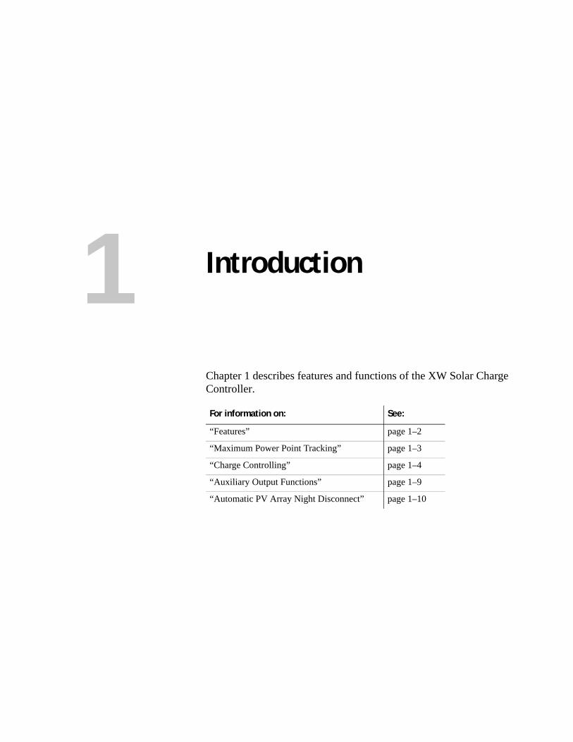
Chapter 1 describes features and functions of the XW Solar Charge Controller.
Chapter 2 contains information and procedures to install the XW Solar Charge Controller. Before installing the XW SCC, read this entire chapter. Depending on your installation, you may need to perform certain installation stages in a different order than the order presented in this chapter.
Chapter 3 contains information and procedures to configure the XW Solar Charge Controller.
Chapter 4 contains information about the operation of the XW Solar Charge Controller.
Chapter 5 contains information about identifying and resolving possible problems with systems using a XW Solar Charge Controller.
Appendix A provides the specifications for the XW Solar Charge Controller.
Appendix B is a guide to the XW Solar Charge Controller monitoring and configuration menus on the XW System Control Panel. The System Control Panel may be installed if the XW SCC is part of a power management system that includes an inverter/charger.
Appendix C provides information on Boost Charging for flooded lead-acid batteries in off-grid applications.
975-0400-01-01 iii
About This Guide
Conventions UsedThe following conventions are used in this guide.
Related InformationYou can find more information about Xantrex Technology Inc. as well as its products and services at www.xantrex.com.
WARNINGWarnings identify conditions that could result in personal injury or loss of life.
CAUTIONCautions identify conditions or practices that could result in damage to the unit or to other equipment.
Important: These notes describe things which are important for you to know, but not as serious as a caution or warning.
iv 975-0400-01-01
Important Safety Instructions
General Safety Instructions
• All electrical work must be done in accordance with local, national, and/or international electrical codes.
• Before installing or using this device, read all instructions and cautionary markings located in (or on) this guide, the unit, the batteries, PV array, and any other equipment used.
• This product is designed for indoor mounting only. Do not expose this unit to rain, snow or liquids of any type.
• To reduce the chance of short-circuits, use insulated tools when installing or working with the unit or any DC source (such as PV, hydro, wind, or batteries).
• Remove all jewelry when installing or working with the unit or any DC source. This will greatly reduce the chance of accidental exposure to live circuits.
• The unit contains more than one live circuit (batteries and PV array). Power may be present at more than one source.
• This product contains no user-serviceable parts.
Battery Safety Information
• Always wear eye protection when working with batteries.
WARNINGThis manual contains important safety instructions that should be followed during the installation and maintenance of this product. Be sure to read, understand, and save these safety instructions.
WARNING: Limitations on useThe XW Solar Charge Controller is not intended for use in connection with life support systems or other medical equipment or devices.
WARNINGA battery can produce the following hazards to personal safety:• electrical shock• burn from high-short-circuit current• fire or explosion from vented gasses.Observe proper precautions when working with or around batteries.
975-0400-01-01 v
Safety
• Remove all jewelry before working with batteries.
• Never work alone. Have someone assist you with the installation or be close enough to come to your aid when working with batteries.
• Always use proper lifting techniques when handling batteries.
• Always use identical types of batteries.
• Never install old or untested batteries. Check each battery’s date code or label to ensure age and type.
• Batteries should be installed in a well-vented area to prevent the possible buildup of explosive gasses. If the batteries are installed inside an enclosure, vent its highest point to the outdoors.
• When installing batteries, allow at least 1 inch of air space between batteries to promote cooling and ventilation.
• NEVER smoke in the vicinity of a battery or generator.
• Always connect the batteries first, then connect the cables to the inverter or controller. This will greatly reduce the chance of spark in the vicinity of the batteries.
• Use insulated tools when working with batteries.
• When connecting batteries, always verify proper voltage and polarity.
• Do not short-circuit battery cables. Fire or explosion can occur.
• In the event of exposure to battery electrolyte, wash the area with soap and water. If acid enters the eyes, flood them with running cold water for at least 15 minutes and get immediate medical attention.
• Always recycle old batteries. Contact your local recycling center for proper disposal information.
FCC Information to the User
This equipment has been tested and found to comply with the limits for a Class B digital device, pursuant to part 15 of the FCC Rules. These limits are designed to provide reasonable protection against harmful interference when the equipment is operated in a residential environment. This equipment generates, uses and can radiate radio frequency energy and, if not installed and used in accordance with the instruction guide, may cause harmful interference to radio communications. However, there is no guarantee that interference will not occur in a particular installation. If this equipment does cause harmful interference to radio or television reception, which can be determined by turning the equipment off and on, the user is encouraged to try to correct the interference by one or more of the following measures:
• Reorient or relocate the receiving antenna.
• Increase the separation between the equipment and the receiver.
• Connect the equipment to a different circuit from that to which the receiver is connected.
• Consult the dealer or an experienced radio/TV technician for help.
vi 975-0400-01-01
Contents
Important Safety Instructions - - - - - - - - - - - - - - - - - - - - - - - - - - - - - - - - - - - - - - - - - - - -v
1 IntroductionFeatures - - - - - - - - - - - - - - - - - - - - - - - - - - - - - - - - - - - - - - - - - - - - - - - - - - - - - - - - - - - - - 1–2Maximum Power Point Tracking - - - - - - - - - - - - - - - - - - - - - - - - - - - - - - - - - - - - - - - - - - - - 1–3Charge Controlling - - - - - - - - - - - - - - - - - - - - - - - - - - - - - - - - - - - - - - - - - - - - - - - - - - - - - 1–4
Three-Stage Battery Charging - - - - - - - - - - - - - - - - - - - - - - - - - - - - - - - - - - - - - - - - - - - 1–4Bulk Stage - - - - - - - - - - - - - - - - - - - - - - - - - - - - - - - - - - - - - - - - - - - - - - - - - - - - - - 1–4Absorption Stage - - - - - - - - - - - - - - - - - - - - - - - - - - - - - - - - - - - - - - - - - - - - - - - - - 1–5Float Stage - - - - - - - - - - - - - - - - - - - - - - - - - - - - - - - - - - - - - - - - - - - - - - - - - - - - - 1–5
Two-Stage Battery Charging - - - - - - - - - - - - - - - - - - - - - - - - - - - - - - - - - - - - - - - - - - - - 1–7No Float Stage - - - - - - - - - - - - - - - - - - - - - - - - - - - - - - - - - - - - - - - - - - - - - - - - - - - 1–7
Battery Temperature Compensation - - - - - - - - - - - - - - - - - - - - - - - - - - - - - - - - - - - - - - - 1–8Equalization Charging - - - - - - - - - - - - - - - - - - - - - - - - - - - - - - - - - - - - - - - - - - - - - - - - 1–8
Auxiliary Output Functions- - - - - - - - - - - - - - - - - - - - - - - - - - - - - - - - - - - - - - - - - - - - - - - - 1–9Load Control - - - - - - - - - - - - - - - - - - - - - - - - - - - - - - - - - - - - - - - - - - - - - - - - - - - - - - - 1–9Vent Fan - - - - - - - - - - - - - - - - - - - - - - - - - - - - - - - - - - - - - - - - - - - - - - - - - - - - - - - - - - 1–9Alarms - - - - - - - - - - - - - - - - - - - - - - - - - - - - - - - - - - - - - - - - - - - - - - - - - - - - - - - - - - - 1–9
Automatic PV Array Night Disconnect - - - - - - - - - - - - - - - - - - - - - - - - - - - - - - - - - - - - - - - - 1–9
2 InstallationPV Array Requirements - - - - - - - - - - - - - - - - - - - - - - - - - - - - - - - - - - - - - - - - - - - - - - - - - - 2–2
MPPT Voltage Range - - - - - - - - - - - - - - - - - - - - - - - - - - - - - - - - - - - - - - - - - - - - - - - - - 2–2Mounting - - - - - - - - - - - - - - - - - - - - - - - - - - - - - - - - - - - - - - - - - - - - - - - - - - - - - - - - - - - - 2–3
Choosing a Location - - - - - - - - - - - - - - - - - - - - - - - - - - - - - - - - - - - - - - - - - - - - - - - - - - 2–3Removing the Wiring Compartment Cover - - - - - - - - - - - - - - - - - - - - - - - - - - - - - - - - - - - 2–5Removing Knockouts - - - - - - - - - - - - - - - - - - - - - - - - - - - - - - - - - - - - - - - - - - - - - - - - - 2–5Mounting the Charge Controller - - - - - - - - - - - - - - - - - - - - - - - - - - - - - - - - - - - - - - - - - - 2–7
Grounding - - - - - - - - - - - - - - - - - - - - - - - - - - - - - - - - - - - - - - - - - - - - - - - - - - - - - - - - - - - 2–7Internal Ground Fault Protection - - - - - - - - - - - - - - - - - - - - - - - - - - - - - - - - - - - - - - - - - - 2–8Disabling Ground Fault Protection for Negative Grounded and Ungrounded Arrays - - - - - - - 2–9
Wiring - - - - - - - - - - - - - - - - - - - - - - - - - - - - - - - - - - - - - - - - - - - - - - - - - - - - - - - - - - - - - 2–10DC Terminal Connector Locations - - - - - - - - - - - - - - - - - - - - - - - - - - - - - - - - - - - - - - - 2–10Wire Size and Over-current Protection Requirements - - - - - - - - - - - - - - - - - - - - - - - - - - - 2–10
Current Rating - - - - - - - - - - - - - - - - - - - - - - - - - - - - - - - - - - - - - - - - - - - - - - - - - - 2–10Minimum Wire Gauge - - - - - - - - - - - - - - - - - - - - - - - - - - - - - - - - - - - - - - - - - - - - - 2–11Over-current Protection - - - - - - - - - - - - - - - - - - - - - - - - - - - - - - - - - - - - - - - - - - - - 2–11Long-distance wire runs - - - - - - - - - - - - - - - - - - - - - - - - - - - - - - - - - - - - - - - - - - - 2–11Maximum One-way Distance and Wire Size - - - - - - - - - - - - - - - - - - - - - - - - - - - - - - 2–12
Connecting the XW SCC - - - - - - - - - - - - - - - - - - - - - - - - - - - - - - - - - - - - - - - - - - - - - - 2–13
975-0400-01-01 vii
Contents
Connecting Multiple Units - - - - - - - - - - - - - - - - - - - - - - - - - - - - - - - - - - - - - - - - - - - - - - - -2–15Aux Output Connections - - - - - - - - - - - - - - - - - - - - - - - - - - - - - - - - - - - - - - - - - - - - - - - - -2–16Disconnecting the Charge Controller - - - - - - - - - - - - - - - - - - - - - - - - - - - - - - - - - - - - - - - - -2–17Network Installation - - - - - - - - - - - - - - - - - - - - - - - - - - - - - - - - - - - - - - - - - - - - - - - - - - - -2–18
Network Components - - - - - - - - - - - - - - - - - - - - - - - - - - - - - - - - - - - - - - - - - - - - - - - -2–18Ordering Network Components - - - - - - - - - - - - - - - - - - - - - - - - - - - - - - - - - - - - - - -2–19
Network Layout - - - - - - - - - - - - - - - - - - - - - - - - - - - - - - - - - - - - - - - - - - - - - - - - - - - -2–19Connecting Network Cable Between Multiple Units - - - - - - - - - - - - - - - - - - - - - - - - - - - -2–20
Installing the Battery Temperature Sensor - - - - - - - - - - - - - - - - - - - - - - - - - - - - - - - - - - - - -2–21Commissioning - - - - - - - - - - - - - - - - - - - - - - - - - - - - - - - - - - - - - - - - - - - - - - - - - - - - - - -2–23
Configuration Screens - - - - - - - - - - - - - - - - - - - - - - - - - - - - - - - - - - - - - - - - - - - - - - - -2–23Commissioning a Single Unit Without a System Control Panel - - - - - - - - - - - - - - - - - - - -2–24Commissioning Multiple Units Without a System Control Panel - - - - - - - - - - - - - - - - - - -2–25Commissioning Units Using a System Control Panel - - - - - - - - - - - - - - - - - - - - - - - - - - -2–27
3 ConfigurationConfiguring the XW SCC - - - - - - - - - - - - - - - - - - - - - - - - - - - - - - - - - - - - - - - - - - - - - - - - 3–2Configuration Menus - - - - - - - - - - - - - - - - - - - - - - - - - - - - - - - - - - - - - - - - - - - - - - - - - - - 3–3
Basic and Advanced Menus - - - - - - - - - - - - - - - - - - - - - - - - - - - - - - - - - - - - - - - - - - - - 3–3Configuring Battery Characteristics and Battery Charging - - - - - - - - - - - - - - - - - - - - - - - - - - 3–5
Setting a Custom Battery Type - - - - - - - - - - - - - - - - - - - - - - - - - - - - - - - - - - - - - - - - - - 3–8Battery Temperature Compensation - - - - - - - - - - - - - - - - - - - - - - - - - - - - - - - - - - - - - - -3–10
Configuring XW SCC Input - - - - - - - - - - - - - - - - - - - - - - - - - - - - - - - - - - - - - - - - - - - - - - -3–11Configuring the Auxiliary Output - - - - - - - - - - - - - - - - - - - - - - - - - - - - - - - - - - - - - - - - - - -3–12
Trigger Source Descriptions - - - - - - - - - - - - - - - - - - - - - - - - - - - - - - - - - - - - - - - - - - - -3–14Trigger Source Configurable Ranges - - - - - - - - - - - - - - - - - - - - - - - - - - - - - - - - - - - - - -3–15
Configuring the LCD - - - - - - - - - - - - - - - - - - - - - - - - - - - - - - - - - - - - - - - - - - - - - - - - - - -3–16Device Menu - - - - - - - - - - - - - - - - - - - - - - - - - - - - - - - - - - - - - - - - - - - - - - - - - - - - - - - - -3–18Resetting to Factory Defaults - - - - - - - - - - - - - - - - - - - - - - - - - - - - - - - - - - - - - - - - - - - - - -3–20
4 OperationViewing Operating Status - - - - - - - - - - - - - - - - - - - - - - - - - - - - - - - - - - - - - - - - - - - - - - - - 4–2
LCD Screens and What They Mean - - - - - - - - - - - - - - - - - - - - - - - - - - - - - - - - - - - - - - - 4–2Normal Operation - - - - - - - - - - - - - - - - - - - - - - - - - - - - - - - - - - - - - - - - - - - - - - - - - - - 4–3
Charge Stages - - - - - - - - - - - - - - - - - - - - - - - - - - - - - - - - - - - - - - - - - - - - - - - - - - - 4–5Dynamic Text - - - - - - - - - - - - - - - - - - - - - - - - - - - - - - - - - - - - - - - - - - - - - - - - - - - 4–6
Monitoring XW SCC Operation - - - - - - - - - - - - - - - - - - - - - - - - - - - - - - - - - - - - - - - - - - - - 4–7Viewing Active Faults and Warnings - - - - - - - - - - - - - - - - - - - - - - - - - - - - - - - - - - - - - - 4–8Viewing Logged System Data - - - - - - - - - - - - - - - - - - - - - - - - - - - - - - - - - - - - - - - - - - -4–11
Daily Logs - - - - - - - - - - - - - - - - - - - - - - - - - - - - - - - - - - - - - - - - - - - - - - - - - - - - -4–12Monthly Logs - - - - - - - - - - - - - - - - - - - - - - - - - - - - - - - - - - - - - - - - - - - - - - - - - - -4–12
Battery Equalization - - - - - - - - - - - - - - - - - - - - - - - - - - - - - - - - - - - - - - - - - - - - - - - - - - - -4–13
viii 975-0400-01-01
Contents
5 TroubleshootingPV Charge Control Troubleshooting- - - - - - - - - - - - - - - - - - - - - - - - - - - - - - - - - - - - - - - - - - 5–2Replacing the Ground Fault Protection Fuse - - - - - - - - - - - - - - - - - - - - - - - - - - - - - - - - - - - - 5–3
A SpecificationsElectrical Specifications - - - - - - - - - - - - - - - - - - - - - - - - - - - - - - - - - - - - - - - - - - - - - - - - - -A–2Default Battery Charging Settings - - - - - - - - - - - - - - - - - - - - - - - - - - - - - - - - - - - - - - - - - - -A–2Mechanical Specifications - - - - - - - - - - - - - - - - - - - - - - - - - - - - - - - - - - - - - - - - - - - - - - - -A–3Output Power Versus Ambient Temperature - - - - - - - - - - - - - - - - - - - - - - - - - - - - - - - - - - - -A–3Optional Accessories - - - - - - - - - - - - - - - - - - - - - - - - - - - - - - - - - - - - - - - - - - - - - - - - - - - -A–4Regulatory Approvals - - - - - - - - - - - - - - - - - - - - - - - - - - - - - - - - - - - - - - - - - - - - - - - - - - -A–4
B XW System Control Panel MenusUsing the XW System Control Panel - - - - - - - - - - - - - - - - - - - - - - - - - - - - - - - - - - - - - - - - -B–2
System Control Panel Menu Map - - - - - - - - - - - - - - - - - - - - - - - - - - - - - - - - - - - - - - - - -B–3Changing Settings Using the System Control Panel - - - - - - - - - - - - - - - - - - - - - - - - - - - - -B–5
Viewing the Select Device Menu - - - - - - - - - - - - - - - - - - - - - - - - - - - - - - - - - - - - - -B–5Viewing the XW SCC Setup Menu - - - - - - - - - - - - - - - - - - - - - - - - - - - - - - - - - - - - -B–5
The Charge Controller Setup Menu - - - - - - - - - - - - - - - - - - - - - - - - - - - - - - - - - - - - - - - - - -B–6Configuration Settings - - - - - - - - - - - - - - - - - - - - - - - - - - - - - - - - - - - - - - - - - - - - - - - - - - -B–7Monitoring the XW SCC - - - - - - - - - - - - - - - - - - - - - - - - - - - - - - - - - - - - - - - - - - - - - - - - B–10
XW SCC Home Screen - - - - - - - - - - - - - - - - - - - - - - - - - - - - - - - - - - - - - - - - - - - - - - - B–10Meters - - - - - - - - - - - - - - - - - - - - - - - - - - - - - - - - - - - - - - - - - - - - - - - - - - - - - - - - - - B–11
C Boost ChargingUsing Boost Charging - - - - - - - - - - - - - - - - - - - - - - - - - - - - - - - - - - - - - - - - - - - - - - - - - - -C–2
Warranty and Return Information - - - - - - - - - - - - - - - - - - - - - - - - - - - - - - - - - - - - WA–1
Index - - - - - - - - - - - - - - - - - - - - - - - - - - - - - - - - - - - - - - - - - - - - - - - - - - - - - - - - - - - - - - - - IX–1
975-0400-01-01 ix

x
1 Introduction
Chapter 1 describes features and functions of the XW Solar Charge Controller.
For information on: See:
“Features” page 1–2
“Maximum Power Point Tracking” page 1–3
“Charge Controlling” page 1–4
“Auxiliary Output Functions” page 1–9
“Automatic PV Array Night Disconnect” page 1–10
Introduction
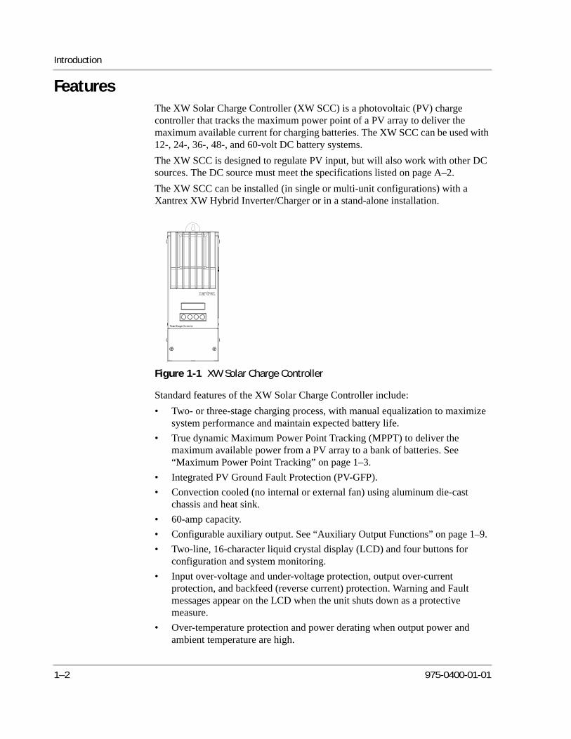
FeaturesThe XW Solar Charge Controller (XW SCC) is a photovoltaic (PV) charge controller that tracks the maximum power point of a PV array to deliver the maximum available current for charging batteries. The XW SCC can be used with 12-, 24-, 36-, 48-, and 60-volt DC battery systems.
The XW SCC is designed to regulate PV input, but will also work with other DC sources. The DC source must meet the specifications listed on page A–2.
The XW SCC can be installed (in single or multi-unit configurations) with a Xantrex XW Hybrid Inverter/Charger or in a stand-alone installation.
Standard features of the XW Solar Charge Controller include:
• Two- or three-stage charging process, with manual equalization to maximize system performance and maintain expected battery life.
• True dynamic Maximum Power Point Tracking (MPPT) to deliver the maximum available power from a PV array to a bank of batteries. See “Maximum Power Point Tracking” on page 1–3.
• Integrated PV Ground Fault Protection (PV-GFP).
• Convection cooled (no internal or external fan) using aluminum die-cast chassis and heat sink.
• 60-amp capacity.
• Configurable auxiliary output. See “Auxiliary Output Functions” on page 1–9.
• Two-line, 16-character liquid crystal display (LCD) and four buttons for configuration and system monitoring.
• Input over-voltage and under-voltage protection, output over-current protection, and backfeed (reverse current) protection. Warning and Fault messages appear on the LCD when the unit shuts down as a protective measure.
• Over-temperature protection and power derating when output power and ambient temperature are high.
Figure 1-1 XW Solar Charge Controller
1–2 975-0400-01-01
Maximum Power Point Tracking
• Battery Temperature Sensor (BTS) to provide automatically temperature-compensated battery charging. If the BTS is lost or damaged, a replacement can be ordered from Xantrex (part number 808-0232-02).
• Xanbus™-enabled. Xanbus is a network communications protocol developed by Xantrex. The XW SCC is able to communicate its settings and activity to other Xanbus-enabled devices, such as the XW Series Inverter/Charger, the XW System Control Panel (SCP), XW Automatic Generator Start (XW-AGS), and other XW Solar Charge Controllers.
• Five-year limited warranty.
Maximum Power Point TrackingMaximum Power Point Tracking allows the XW SCC to harvest the maximum energy available from the PV array and deliver it to the batteries.
The MPPT algorithm continuously adjusts the operating points in an attempt to find the maximum power point of the array. The algorithm can then determine if it is harvesting more or less power than the previous operating points.
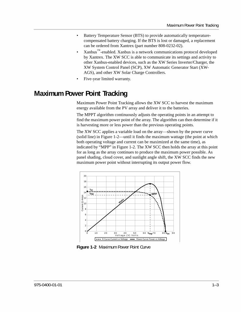
The XW SCC applies a variable load on the array—shown by the power curve (solid line) in Figure 1-2—until it finds the maximum wattage (the point at which both operating voltage and current can be maximized at the same time), as indicated by “MPP” in Figure 1-2. The XW SCC then holds the array at this point for as long as the array continues to produce the maximum power possible. As panel shading, cloud cover, and sunlight angle shift, the XW SCC finds the new maximum power point without interrupting its output power flow.
Figure 1-2 Maximum Power Point Curve
20
18
16
14
12
10
8
6
4
2
0
Cu
rre
nt (I
) A
mp
s
0 1 0 2 0 3 0 4 0 5 0 6 0 7 0 8 0 9 0Vo l t ag e ( V) Vo l t s
Isc
Imp MPP
Vmp Voc
Watts
975-0400-01-01 1–3
Introduction
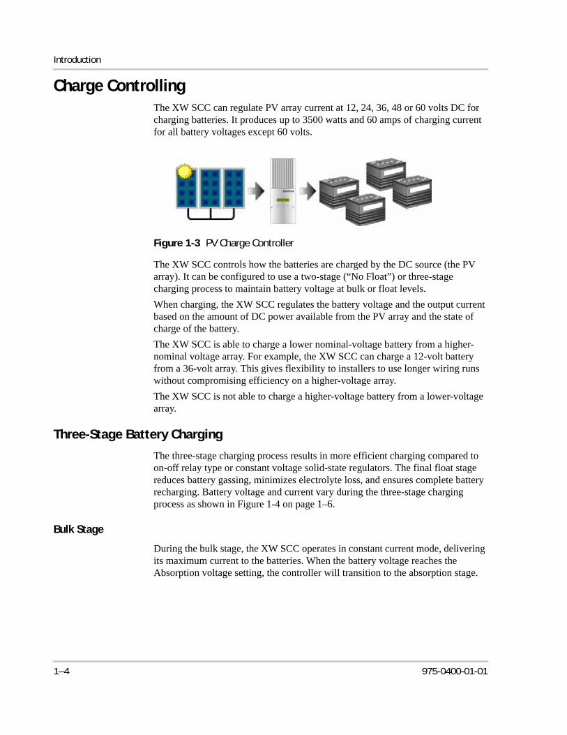
Charge ControllingThe XW SCC can regulate PV array current at 12, 24, 36, 48 or 60 volts DC for charging batteries. It produces up to 3500 watts and 60 amps of charging current for all battery voltages except 60 volts.
The XW SCC controls how the batteries are charged by the DC source (the PV array). It can be configured to use a two-stage (“No Float”) or three-stage charging process to maintain battery voltage at bulk or float levels.
When charging, the XW SCC regulates the battery voltage and the output current based on the amount of DC power available from the PV array and the state of charge of the battery.
The XW SCC is able to charge a lower nominal-voltage battery from a higher-nominal voltage array. For example, the XW SCC can charge a 12-volt battery from a 36-volt array. This gives flexibility to installers to use longer wiring runs without compromising efficiency on a higher-voltage array.
The XW SCC is not able to charge a higher-voltage battery from a lower-voltage array.
Three-Stage Battery Charging
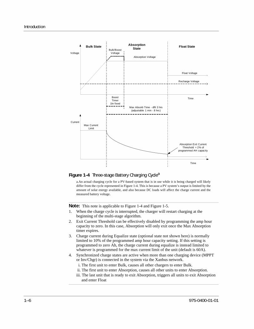
The three-stage charging process results in more efficient charging compared to on-off relay type or constant voltage solid-state regulators. The final float stage reduces battery gassing, minimizes electrolyte loss, and ensures complete battery recharging. Battery voltage and current vary during the three-stage charging process as shown in Figure 1-4 on page 1–6.
Bulk Stage
During the bulk stage, the XW SCC operates in constant current mode, delivering its maximum current to the batteries. When the battery voltage reaches the Absorption voltage setting, the controller will transition to the absorption stage.
Figure 1-3 PV Charge Controller
1–4 975-0400-01-01
Charge Controlling
Absorption Stage
During the absorption stage, the XW SCC begins operating in Constant Voltage mode and the current falls gradually as the amp hours are returned to the battery. The voltage limit used for the first 60 minutes of this stage is the Bulk Voltage setting. The voltage limit used for the remaining time in this stage is the Absorption Voltage setting. By default, the Bulk voltage setting and the Absorption voltage setting are the same for all battery types. The default voltage limit settings (Bulk and Absorption) can be adjusted if the battery type is set to Custom. For flooded lead acid batteries only, a custom charging scheme can be used which sets the Bulk voltage higher than the Absorption voltage. The result of this will be a boost voltage charge level, which has been found beneficial for ensuring enough amp hours are returned to the battery bank for off grid installations. For detailed information on how Boost charging works and when it is recommended, please refer to Appendix C, “Boost Charging”. The XW SCC transitions to the float stage if either one of two conditions are met:
1. The charge current allowed by the batteries falls below the exit current threshold, which is equal to 2% of the programmed battery capacity (for a 500 amp-hour battery bank, this would be 10 amps), for one minute.
2. The XW SCC has been in absorption for the programmed maximum absorption time limit. The default is 3 hours, but the time limit is programmable from 1 minute to 8 hours.
Float Stage
During the float stage, the voltage of the battery is held at the float voltage setting. Full current can be provided to the loads connected to the battery during the float stage from the PV array. When battery voltage drops below the ReCharge Volts setting for 1 minute, a new bulk cycle will be triggered.
975-0400-01-01 1–5
Introduction
Figure 1-4 Three-stage Battery Charging Cyclea
a.An actual charging cycle for a PV-based system that is in use while it is being charged will likelydiffer from the cycle represented in Figure 1-4. This is because a PV system’s output is limited by theamount of solar energy available, and also because DC loads will affect the charge current and themeasured battery voltage.
Note: This note is applicable to Figure 1-4 and Figure 1-5.1. When the charge cycle is interrupted, the charger will restart charging at the
beginning of the multi-stage algorithm. 2. Exit Current Threshold can be effectively disabled by programming the amp hour
capacity to zero. In this case, Absorption will only exit once the Max Absorption timer expires.
3. Charge current during Equalize state (optional state not shown here) is normally limited to 10% of the programmed amp hour capacity setting. If this setting is programmed to zero Ah, the charge current during equalize is instead limited to whatever is programmed for the max current limit of the unit (default is 60A).
4. Synchronized charge states are active when more than one charging device (MPPT or Inv/Chgr) is connected in the system via the Xanbus network. i. The first unit to enter Bulk, causes all other chargers to enter Bulk. ii. The first unit to enter Absorption, causes all other units to enter Absorption.iii. The last unit that is ready to exit Absorption, triggers all units to exit Absorption
and enter Float
Float StateAbsorption
StateBulk State
Current
Time
Max Current Limit
Voltage
Time
Absorption Voltage
Float Voltage
Max Absorb Time - dflt 3 hrs (adjustable 1 min - 8 hrs )
Bulk/Boost Voltage
Boost Timer
1hr fixed
Absorption Exit Current Threshold = 2% of
programmed AH capacity
Recharge Voltage
1–6 975-0400-01-01
Charge Controlling
Two-Stage Battery Charging
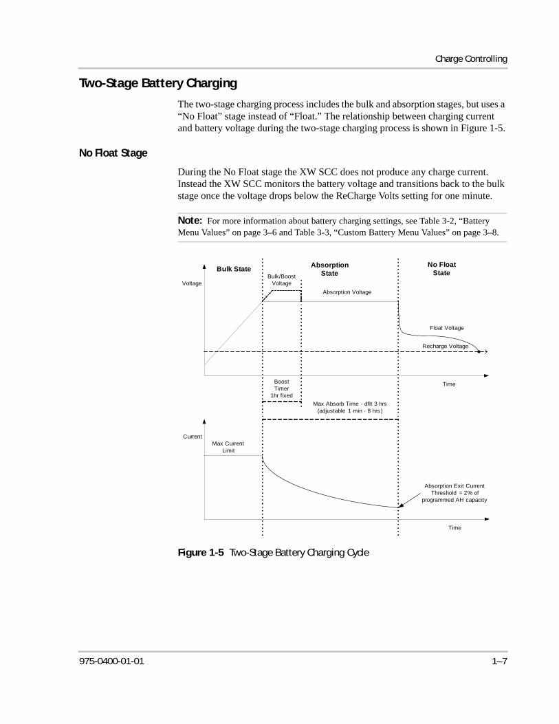
The two-stage charging process includes the bulk and absorption stages, but uses a “No Float” stage instead of “Float.” The relationship between charging current and battery voltage during the two-stage charging process is shown in Figure 1-5.
No Float Stage
During the No Float stage the XW SCC does not produce any charge current. Instead the XW SCC monitors the battery voltage and transitions back to the bulk stage once the voltage drops below the ReCharge Volts setting for one minute.
Note: For more information about battery charging settings, see Table 3-2, “Battery Menu Values” on page 3–6 and Table 3-3, “Custom Battery Menu Values” on page 3–8.
Figure 1-5 Two-Stage Battery Charging Cycle
Absorption State
Bulk State
Current
Time
Max Current Limit
Voltage
Time
Absorption Voltage
Float Voltage
Max Absorb Time - dflt 3 hrs (adjustable 1 min - 8 hrs )
Bulk/Boost Voltage
Boost Timer
1hr fixed
Absorption Exit Current Threshold = 2% of
programmed AH capacity
Recharge Voltage
No Float State
975-0400-01-01 1–7
Introduction
Battery Temperature Compensation
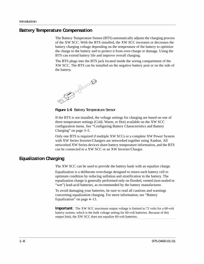
The Battery Temperature Sensor (BTS) automatically adjusts the charging process of the XW SCC. With the BTS installed, the XW SCC increases or decreases the battery charging voltage depending on the temperature of the battery to optimize the charge to the battery and to protect it from over-charge or damage. Using the BTS can extend battery life and improve overall charging.
The BTS plugs into the BTS jack located inside the wiring compartment of the XW SCC. The BTS can be installed on the negative battery post or on the side of the battery.
If the BTS is not installed, the voltage settings for charging are based on one of three temperature settings (Cold, Warm, or Hot) available on the XW SCC configuration menu. See “Configuring Battery Characteristics and Battery Charging” on page 3–5.
Only one BTS is required if multiple XW SCCs or a complete XW Power System with XW Series Inverter/Chargers are networked together using Xanbus. All networked XW Series devices share battery temperature information, and the BTS can be connected to a XW SCC or an XW Inverter/Charger.
Equalization Charging
The XW SCC can be used to provide the battery bank with an equalize charge.
Equalization is a deliberate overcharge designed to return each battery cell to optimum condition by reducing sulfation and stratification in the battery. The equalization charge is generally performed only on flooded, vented (non-sealed or “wet”) lead-acid batteries, as recommended by the battery manufacturer.
To avoid damaging your batteries, be sure to read all cautions and warnings concerning equalization charging. For more information, see “Battery Equalization” on page 4–13.
Figure 1-6 Battery Temperature Sensor
Important: The XW SCC maximum output voltage is limited to 72 volts for a 60-volt battery system, which is the bulk voltage setting for 60-volt batteries. Because of this output limit, the XW SCC does not equalize 60-volt batteries.
1–8 975-0400-01-01
Auxiliary Output Functions
Auxiliary Output FunctionsThe XW SCC has a configurable auxiliary output (producing 5 to 13 volts and up to 200 milliamps) to drive a relay for load control or to turn on devices such as vent fans or indicator alarms. The auxiliary output can be configured to perform only one function at a time.
See “Configuring the Auxiliary Output” on page 3–12 for information about auxiliary output trigger sources and how to enable and configure the auxiliary output for your application.
Load ControlThe XW SCC auxiliary output can be configured to drive a relay to disconnect or reconnect loads depending on battery voltage. This load control function enables the XW SCC to help prevent damage to the battery from over-discharge during periods of poor charging (due to ambient temperature, for example) or excessive loads.
Vent FanThe XW SCC auxiliary output can be configured to power a small DC fan to clear a battery compartment of harmful gases. The XW SCC auxiliary output must be configured to activate when the batteries reach their gassing voltage.
AlarmsThe auxiliary output can be configured to trigger an alarm or indicator light when a pre-set condition occurs, such as low or high battery voltage, high PV array voltage, or a XW SCC fault.
CAUTIONThe auxiliary output is intended only to energize a low-current circuit such as a relay coil. Connection to a high-amperage device will open the fuse in the common line and possibly damage the unit.
975-0400-01-01 1–9
1–10
Automatic PV Array Night DisconnectAt night, or when the PV array voltage is less than the battery voltage, the XW SCC opens an internal relay to prevent battery current from flowing back to the PV array. In this mode of operation the XW SCC draws minimal power from the battery.
This automatic night-time disconnect eliminates the need for a blocking diode between the battery and the PV array. If the PV array consists of thin-film or amorphous solar modules, diodes may still be required to prevent damage during times of partial shading of the array. Check the documentation provided with the PV modules.
2 Installation
Chapter 2 contains information and procedures to install the XW Solar Charge Controller. Before installing the XW SCC, read this entire chapter. Depending on your installation, you may need to perform certain installation stages in a different order than the order presented in this chapter.
For information on: See:
“PV Array Requirements” page 2–2
“Mounting” page 2–3
“Grounding” page 2–7
“Wiring” page 2–10
“Installing the Battery Temperature Sensor” page 2–21
“Commissioning” page 2–23
Installation
PV Array Requirements
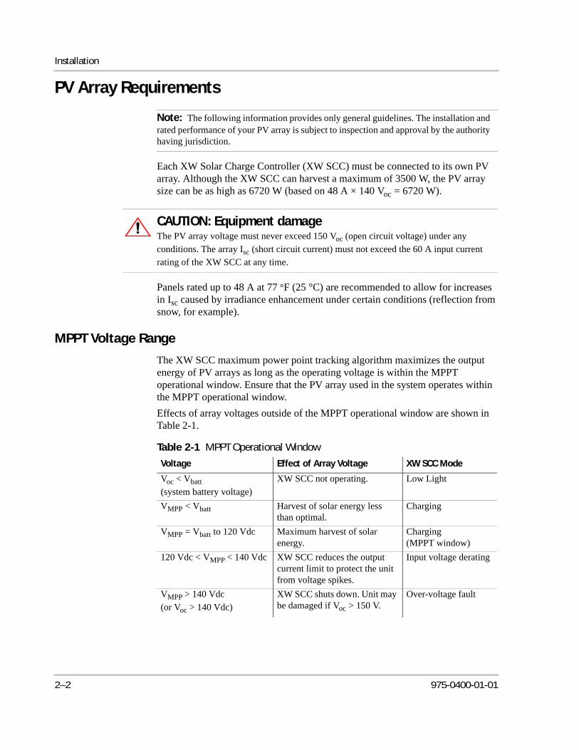
Each XW Solar Charge Controller (XW SCC) must be connected to its own PV array. Although the XW SCC can harvest a maximum of 3500 W, the PV array size can be as high as 6720 W (based on 48 A × 140 Voc = 6720 W).
Panels rated up to 48 A at 77 °F (25 °C) are recommended to allow for increases in Isc caused by irradiance enhancement under certain conditions (reflection from snow, for example).
MPPT Voltage Range
The XW SCC maximum power point tracking algorithm maximizes the output energy of PV arrays as long as the operating voltage is within the MPPT operational window. Ensure that the PV array used in the system operates within the MPPT operational window.
Effects of array voltages outside of the MPPT operational window are shown in Table 2-1.
Note: The following information provides only general guidelines. The installation and rated performance of your PV array is subject to inspection and approval by the authority having jurisdiction.
CAUTION: Equipment damageThe PV array voltage must never exceed 150 Voc (open circuit voltage) under any
conditions. The array Isc (short circuit current) must not exceed the 60 A input current
rating of the XW SCC at any time.
Table 2-1 MPPT Operational Window
Voltage Effect of Array Voltage XW SCC Mode
Voc < Vbatt
(system battery voltage)
XW SCC not operating. Low Light
VMPP < Vbatt Harvest of solar energy less than optimal.
Charging
VMPP = Vbatt to 120 Vdc Maximum harvest of solar energy.
Charging (MPPT window)
120 Vdc < VMPP < 140 Vdc XW SCC reduces the output current limit to protect the unit from voltage spikes.
Input voltage derating
VMPP > 140 Vdc
(or Voc > 140 Vdc)
XW SCC shuts down. Unit may be damaged if Voc > 150 V.
Over-voltage fault
2–2 975-0400-01-01
Mounting
MountingThe instructions in this chapter are applicable to the typical stand-alone installation. Installation procedures will vary according to your specific application. For special applications, consult a qualified electrician or your Xantrex Certified Dealer.
If installing the XW SCC as part of an XW System, see the XW Power System Installation Guide for additional information.
Choosing a Location
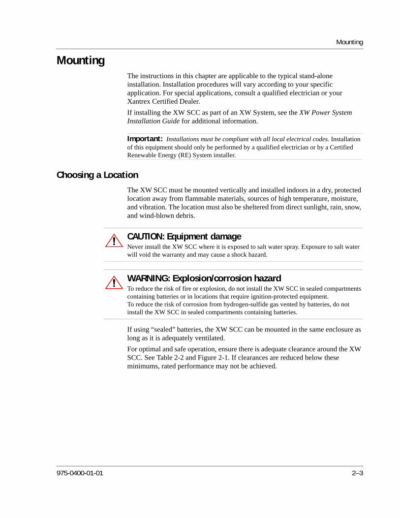
The XW SCC must be mounted vertically and installed indoors in a dry, protected location away from flammable materials, sources of high temperature, moisture, and vibration. The location must also be sheltered from direct sunlight, rain, snow, and wind-blown debris.
If using “sealed” batteries, the XW SCC can be mounted in the same enclosure as long as it is adequately ventilated.
For optimal and safe operation, ensure there is adequate clearance around the XW SCC. See Table 2-2 and Figure 2-1. If clearances are reduced below these minimums, rated performance may not be achieved.
Important: Installations must be compliant with all local electrical codes. Installation of this equipment should only be performed by a qualified electrician or by a Certified Renewable Energy (RE) System installer.
CAUTION: Equipment damageNever install the XW SCC where it is exposed to salt water spray. Exposure to salt water will void the warranty and may cause a shock hazard.
WARNING: Explosion/corrosion hazardTo reduce the risk of fire or explosion, do not install the XW SCC in sealed compartments containing batteries or in locations that require ignition-protected equipment. To reduce the risk of corrosion from hydrogen-sulfide gas vented by batteries, do not install the XW SCC in sealed compartments containing batteries.
975-0400-01-01 2–3
Installation
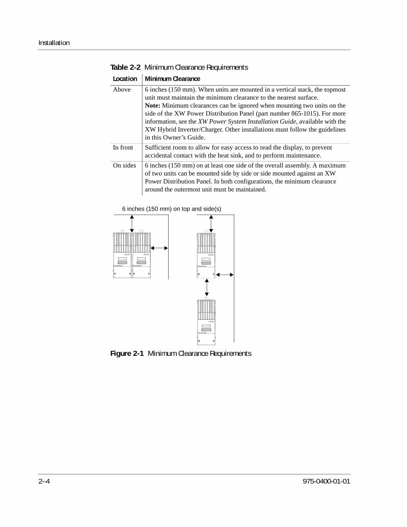
Table 2-2 Minimum Clearance Requirements
Location Minimum Clearance
Above 6 inches (150 mm). When units are mounted in a vertical stack, the topmost unit must maintain the minimum clearance to the nearest surface.Note: Minimum clearances can be ignored when mounting two units on the side of the XW Power Distribution Panel (part number 865-1015). For more information, see the XW Power System Installation Guide, available with the XW Hybrid Inverter/Charger. Other installations must follow the guidelines in this Owner’s Guide.
In front Sufficient room to allow for easy access to read the display, to prevent accidental contact with the heat sink, and to perform maintenance.
On sides 6 inches (150 mm) on at least one side of the overall assembly. A maximum of two units can be mounted side by side or side mounted against an XW Power Distribution Panel. In both configurations, the minimum clearance around the outermost unit must be maintained.
Figure 2-1 Minimum Clearance Requirements
6 inches (150 mm) on top and side(s)
2–4 975-0400-01-01
Mounting
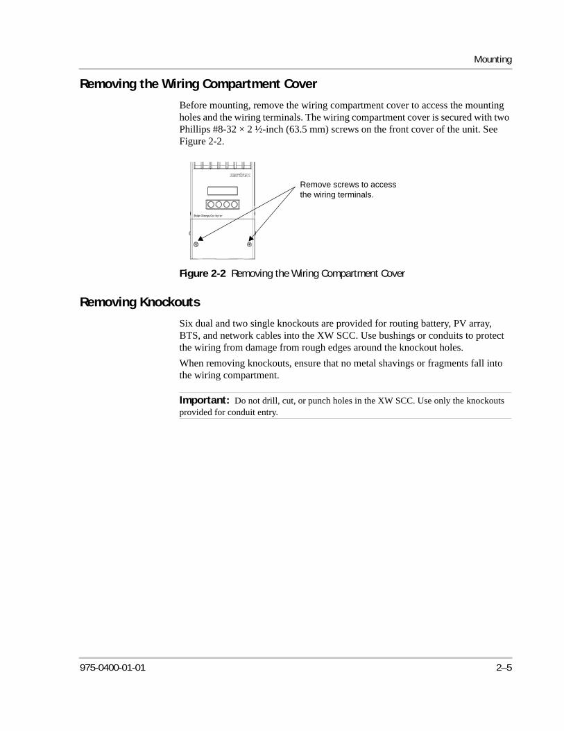
Removing the Wiring Compartment Cover
Before mounting, remove the wiring compartment cover to access the mounting holes and the wiring terminals. The wiring compartment cover is secured with two Phillips #8-32 × 2 ½-inch (63.5 mm) screws on the front cover of the unit. See Figure 2-2.
Removing Knockouts
Six dual and two single knockouts are provided for routing battery, PV array, BTS, and network cables into the XW SCC. Use bushings or conduits to protect the wiring from damage from rough edges around the knockout holes.
When removing knockouts, ensure that no metal shavings or fragments fall into the wiring compartment.
Figure 2-2 Removing the Wiring Compartment Cover
Remove screws to access the wiring terminals.
Important: Do not drill, cut, or punch holes in the XW SCC. Use only the knockouts provided for conduit entry.
975-0400-01-01 2–5
Installation
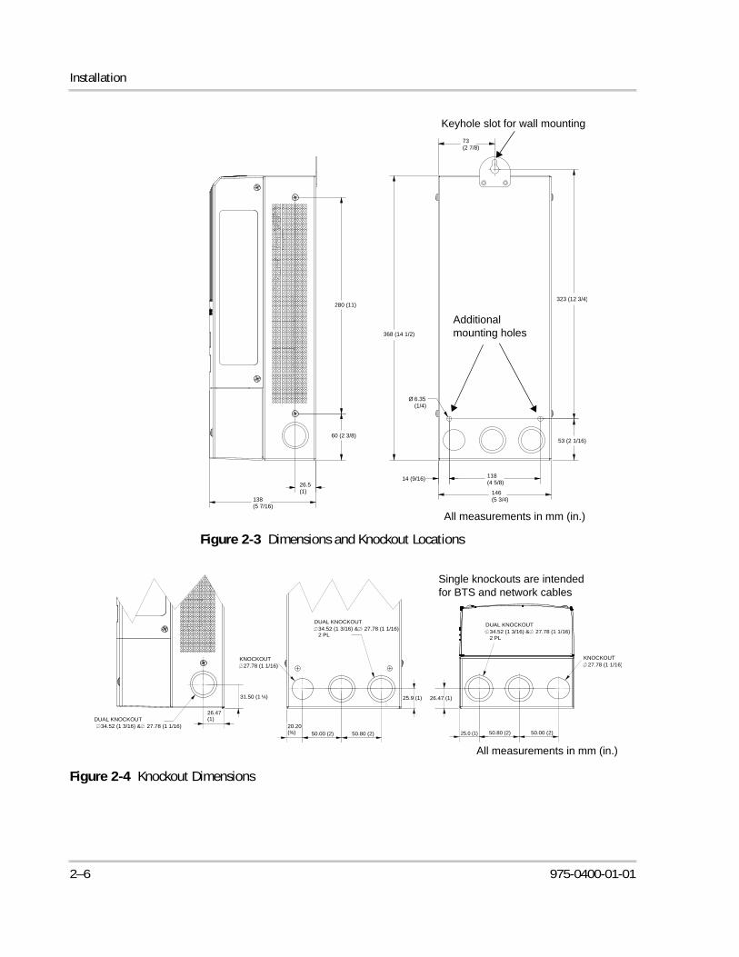
Figure 2-3 Dimensions and Knockout Locations
Figure 2-4 Knockout Dimensions
26.5(1)
138(5 7/16)
60 (2 3/8)
280 (11)
Ø 6.35(1/4)
146(5 3/4)
14 (9/16) 118(4 5/8)
53 (2 1/16)
368 (14 1/2)
323 (12 3/4)
73(2 7/8)
Keyhole slot for wall mounting
Additional mounting holes
All measurements in mm (in.)
34.52 (1 3/16) & 27.78 (1 1/16)DUAL KNOCKOUT
26.47(1)
31.50 (1 ¼)
20.20(¾) 50.00 (2) 50.80 (2)
25.9 (1)
27.78 (1 1/16)KNOCKOUT
25.0 (1) 50.80 (2)
26.47 (1)
50.00 (2)
KNOCKOUT27.78 (1 1/16)
34.52 (1 3/16) & 27.78 (1 1/16)2 PL
DUAL KNOCKOUT
34.52 (1 3/16) & 27.78 (1 1/16)2 PL
DUAL KNOCKOUT
All measurements in mm (in.)
Single knockouts are intended for BTS and network cables
2–6 975-0400-01-01
Grounding
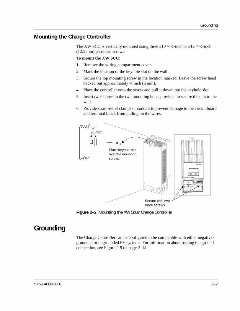
Mounting the Charge Controller
The XW SCC is vertically mounted using three #10 × ½-inch or #12 × ½-inch (12.5 mm) pan-head screws.
To mount the XW SCC:
1. Remove the wiring compartment cover.
2. Mark the location of the keyhole slot on the wall.
3. Secure the top mounting screw in the location marked. Leave the screw head backed out approximately ¼ inch (6 mm).
4. Place the controller onto the screw and pull it down into the keyhole slot.
5. Insert two screws in the two mounting holes provided to secure the unit to the wall.
6. Provide strain-relief clamps or conduit to prevent damage to the circuit board and terminal block from pulling on the wires.
GroundingThe Charge Controller can be configured to be compatible with either negative-grounded or ungrounded PV systems. For information about routing the ground connection, see Figure 2-9 on page 2–14.
Figure 2-5 Mounting the XW Solar Charge Controller
Secure with two more screws.
Place keyhole slot over the mounting screw.
¼"(6 mm)
975-0400-01-01 2–7
Installation
The maximum size of the ground conductor is #6 AWG (16 mm2). This wire gauge is determined by electrical code requirements regarding conduit knockout sizes, wire bending radius, and space available within the XW SCC wiring compartment. For ground conductor requirements for your specific installation, consult your local electrical code.
Internal Ground Fault Protection
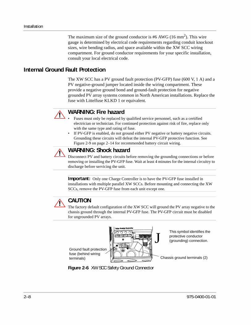
The XW SCC has a PV ground fault protection (PV-GFP) fuse (600 V, 1 A) and a PV negative-ground jumper located inside the wiring compartment. These provide a negative ground bond and ground-fault protection for negative grounded PV array systems common in North American installations. Replace the fuse with Littelfuse KLKD 1 or equivalent.
WARNING: Fire hazard• Fuses must only be replaced by qualified service personnel, such as a certified
electrician or technician. For continued protection against risk of fire, replace only with the same type and rating of fuse.
• If PV-GFP is enabled, do not ground either PV negative or battery negative circuits. Grounding these circuits will defeat the internal PV-GFP protective function. See Figure 2-9 on page 2–14 for recommended battery circuit wiring.
WARNING: Shock hazardDisconnect PV and battery circuits before removing the grounding connections or before removing or installing the PV-GFP fuse. Wait at least 4 minutes for the internal circuitry to discharge before servicing the unit.
Important: Only one Charge Controller is to have the PV-GFP fuse installed in installations with multiple parallel XW SCCs. Before mounting and connecting the XW SCCs, remove the PV-GFP fuse from each unit except one.
CAUTIONThe factory default configuration of the XW SCC will ground the PV array negative to the chassis ground through the internal PV-GFP fuse. The PV-GFP circuit must be disabled for ungrounded PV arrays.
Figure 2-6 XW SCC Safety Ground Connector
Chassis ground terminals (2)
This symbol identifies the protective conductor (grounding) connection.J
Ground fault protection fuse (behind wiring terminals)
2–8 975-0400-01-01
Grounding
Disabling Ground Fault Protection for Negative Grounded and Ungrounded Arrays
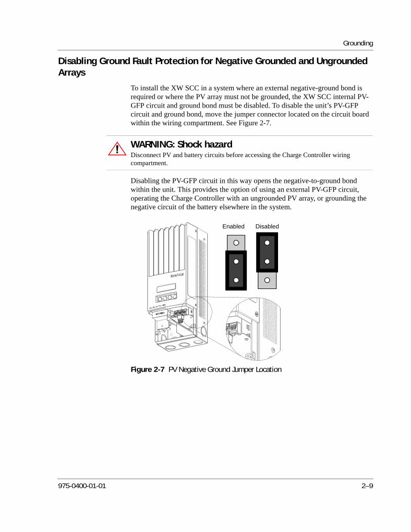
To install the XW SCC in a system where an external negative-ground bond is required or where the PV array must not be grounded, the XW SCC internal PV-GFP circuit and ground bond must be disabled. To disable the unit’s PV-GFP circuit and ground bond, move the jumper connector located on the circuit board within the wiring compartment. See Figure 2-7.
Disabling the PV-GFP circuit in this way opens the negative-to-ground bond within the unit. This provides the option of using an external PV-GFP circuit, operating the Charge Controller with an ungrounded PV array, or grounding the negative circuit of the battery elsewhere in the system.
WARNING: Shock hazardDisconnect PV and battery circuits before accessing the Charge Controller wiring compartment.
Figure 2-7 PV Negative Ground Jumper Location
Enabled Disabled
975-0400-01-01 2–9
Installation
Wiring
DC Terminal Connector Locations
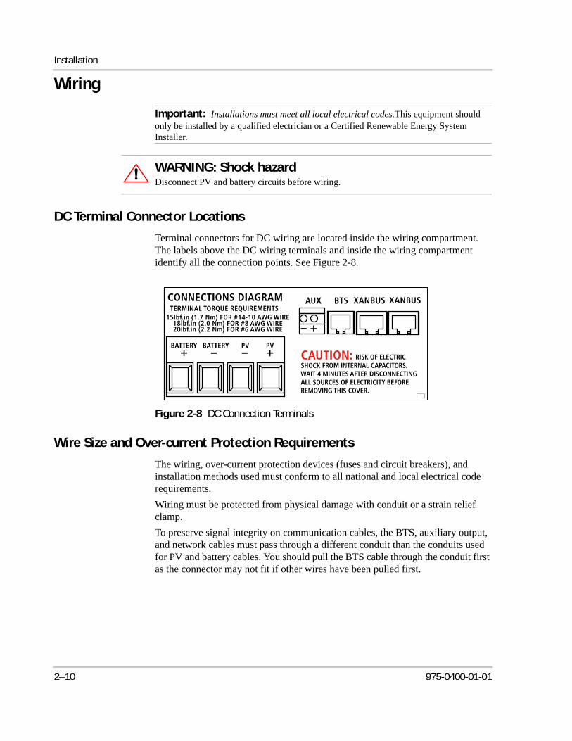
Terminal connectors for DC wiring are located inside the wiring compartment. The labels above the DC wiring terminals and inside the wiring compartment identify all the connection points. See Figure 2-8.
Wire Size and Over-current Protection Requirements
The wiring, over-current protection devices (fuses and circuit breakers), and installation methods used must conform to all national and local electrical code requirements.
Wiring must be protected from physical damage with conduit or a strain relief clamp.
To preserve signal integrity on communication cables, the BTS, auxiliary output, and network cables must pass through a different conduit than the conduits used for PV and battery cables. You should pull the BTS cable through the conduit first as the connector may not fit if other wires have been pulled first.
Important: Installations must meet all local electrical codes.This equipment should only be installed by a qualified electrician or a Certified Renewable Energy System Installer.
WARNING: Shock hazardDisconnect PV and battery circuits before wiring.
Figure 2-8 DC Connection Terminals
2–10 975-0400-01-01
Wiring
Current Rating
The XW SCC PV input is rated for 60 A maximum Isc. Since PV outputs can vary due to the array size or sunlight angle, the safe minimum wire size must be chosen for maximum array short-circuit current. Consult PV array manufacturer specifications.
Minimum Wire Gauge
For installations where the PV array output is the maximum allowable 60 A Isc, the minimum allowable wire gauge is #6 AWG (16 mm2) copper wire with a 90 °C (194 °F) insulation rating. This wire gauge is determined by electrical code requirements regarding conduit knockout sizes, wire bending radius, and space available within the XW SCC wiring compartment.
No crimp-on terminals or lugs are required.
Over-current Protection
Over-current protection must be installed to protect the XW SCC from short circuits and to provide a means of disconnecting the XW SCC. Consult local electrical codes to establish the correct fuse or circuit breaker rating.
Battery Circuit
The NEC requires the battery circuit to be protected with a device rated for 125% of the rating of the circuit. The DC-rated fuse or circuit breaker between the battery and the XW SCC must be rated for 1.25 × 60 A (the maximum current rating of the XW SCC).
PV Circuit
A PV disconnect device between the PV array and the XW SCC must be rated for 60 A.
Long-distance wire runs
If there is a significant distance between the PV array and the XW SCC or between the XW SCC and the battery, larger wires can be used to reduce the voltage drop and improve performance. Refer to Table 2-3.
WARNING: Equipment damageDo not connect an array capable of delivering over 60 A Isc to the XW SCC. Wire sizes
larger than #6 AWG (16 mm2) may be used to reduce resistive losses but should not be installed directly into the XW SCC. Use a splicer block or similar to connect wires of different gauges together. Follow manufacturer’s recommendations for torque and mounting.
975-0400-01-01 2–11
Installation
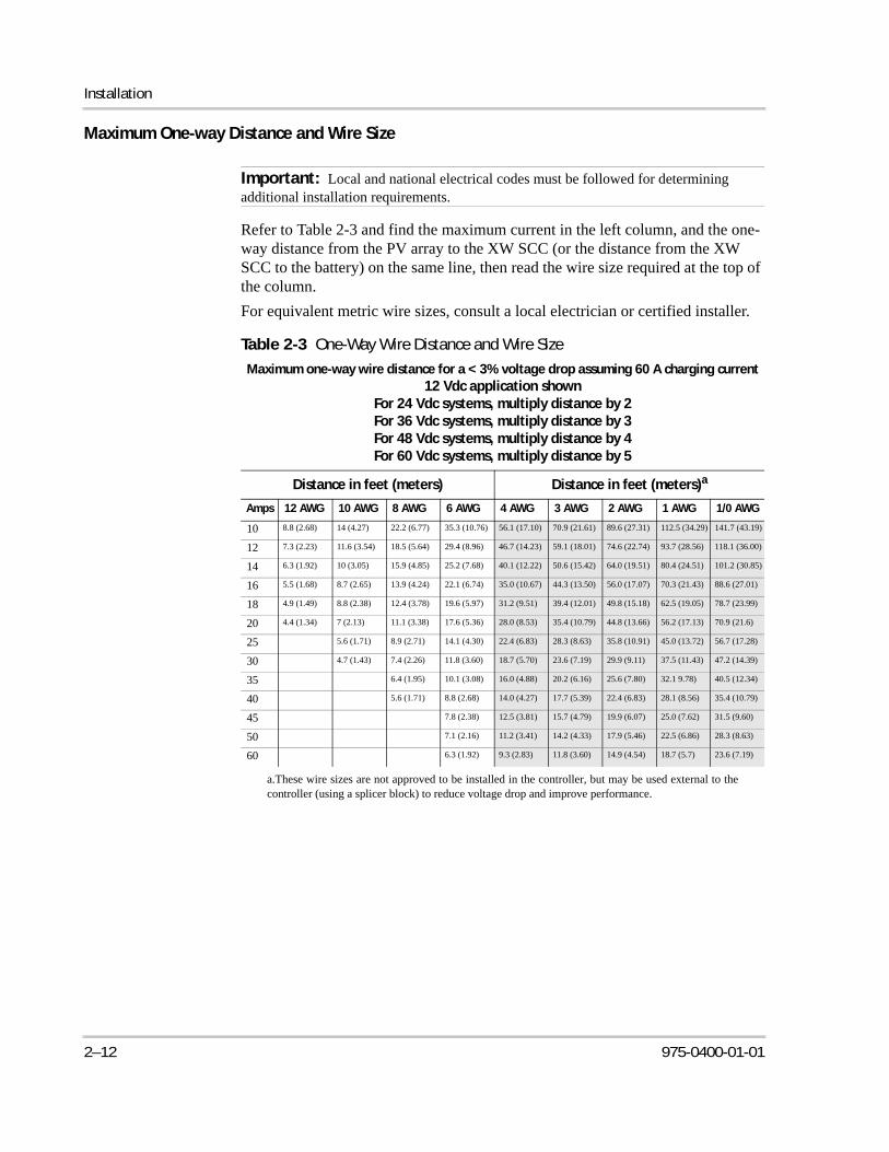
Maximum One-way Distance and Wire Size
Refer to Table 2-3 and find the maximum current in the left column, and the one-way distance from the PV array to the XW SCC (or the distance from the XW SCC to the battery) on the same line, then read the wire size required at the top of the column.
For equivalent metric wire sizes, consult a local electrician or certified installer.
Important: Local and national electrical codes must be followed for determining additional installation requirements.
Table 2-3 One-Way Wire Distance and Wire Size
Maximum one-way wire distance for a < 3% voltage drop assuming 60 A charging current12 Vdc application shown
For 24 Vdc systems, multiply distance by 2For 36 Vdc systems, multiply distance by 3For 48 Vdc systems, multiply distance by 4For 60 Vdc systems, multiply distance by 5
Distance in feet (meters) Distance in feet (meters)a
a.These wire sizes are not approved to be installed in the controller, but may be used external to thecontroller (using a splicer block) to reduce voltage drop and improve performance.
Amps 12 AWG 10 AWG 8 AWG 6 AWG 4 AWG 3 AWG 2 AWG 1 AWG 1/0 AWG
10 8.8 (2.68) 14 (4.27) 22.2 (6.77) 35.3 (10.76) 56.1 (17.10) 70.9 (21.61) 89.6 (27.31) 112.5 (34.29) 141.7 (43.19)
12 7.3 (2.23) 11.6 (3.54) 18.5 (5.64) 29.4 (8.96) 46.7 (14.23) 59.1 (18.01) 74.6 (22.74) 93.7 (28.56) 118.1 (36.00)
14 6.3 (1.92) 10 (3.05) 15.9 (4.85) 25.2 (7.68) 40.1 (12.22) 50.6 (15.42) 64.0 (19.51) 80.4 (24.51) 101.2 (30.85)
16 5.5 (1.68) 8.7 (2.65) 13.9 (4.24) 22.1 (6.74) 35.0 (10.67) 44.3 (13.50) 56.0 (17.07) 70.3 (21.43) 88.6 (27.01)
18 4.9 (1.49) 8.8 (2.38) 12.4 (3.78) 19.6 (5.97) 31.2 (9.51) 39.4 (12.01) 49.8 (15.18) 62.5 (19.05) 78.7 (23.99)
20 4.4 (1.34) 7 (2.13) 11.1 (3.38) 17.6 (5.36) 28.0 (8.53) 35.4 (10.79) 44.8 (13.66) 56.2 (17.13) 70.9 (21.6)
25 5.6 (1.71) 8.9 (2.71) 14.1 (4.30) 22.4 (6.83) 28.3 (8.63) 35.8 (10.91) 45.0 (13.72) 56.7 (17.28)
30 4.7 (1.43) 7.4 (2.26) 11.8 (3.60) 18.7 (5.70) 23.6 (7.19) 29.9 (9.11) 37.5 (11.43) 47.2 (14.39)
35 6.4 (1.95) 10.1 (3.08) 16.0 (4.88) 20.2 (6.16) 25.6 (7.80) 32.1 9.78) 40.5 (12.34)
40 5.6 (1.71) 8.8 (2.68) 14.0 (4.27) 17.7 (5.39) 22.4 (6.83) 28.1 (8.56) 35.4 (10.79)
45 7.8 (2.38) 12.5 (3.81) 15.7 (4.79) 19.9 (6.07) 25.0 (7.62) 31.5 (9.60)
50 7.1 (2.16) 11.2 (3.41) 14.2 (4.33) 17.9 (5.46) 22.5 (6.86) 28.3 (8.63)
60 6.3 (1.92) 9.3 (2.83) 11.8 (3.60) 14.9 (4.54) 18.7 (5.7) 23.6 (7.19)
2–12 975-0400-01-01
Wiring
Connecting the XW SCC
The following procedure is illustrated in Figure 2-9.
To connect the XW SCC:
1. Ensure the PV array disconnect and battery disconnect are turned off.
2. Ground the XW SCC. Connect a grounding conductor between an XW SCC ground lug and the system ground (as shown in Figure 2-9).
3. Connect the PV array negative (–) output to the XW SCC terminal marked PV –.
4. Connect the PV array’s positive (+) output to the PV array disconnect.
5. Route another positive (+) cable from the other end of the PV disconnect to the XW SCC terminal marked PV +.
6. Connect the negative (–) battery cable to the XW SCC terminal marked BAT –.
7. Connect a positive (+) cable from the XW SCC terminal marked BAT + to the battery disconnect.
8. Connect a second positive (+) cable to the other side of the battery disconnect and connect to the positive (+) battery terminal.
9. Torque the XW SCC terminals according to the following table:
WARNING: Shock hazardWhenever a PV array is exposed to light, a shock hazard exists at the output wires or exposed terminals. To reduce the risk of shock during installation, cover the array with an opaque (dark) material before making the connections.
WARNING: Shock hazardDo not connect the battery negative to ground. Bonding the battery negative to ground disables the unit’s internal PV ground-fault protection. For more information, see “Grounding” on page 2–7. See Figure 2-9 on page 2–14 for correct routing of the battery negative.
CAUTION: Equipment damageDo not connect the PV negative and battery negative terminals together anywhere in the system, including the XW Power Distribution Panel or other DC disconnect. The PV negative and battery negative must be connected to separate terminals as marked on the unit.
CAUTION: Reverse polarity damageBefore making the final DC connection or closing the DC breaker or disconnect, check cable polarity at both the battery and the XW SCC. Positive (+) must be connected to positive (+). Negative (–) must be connected to negative (–).
975-0400-01-01 2–13
Installation
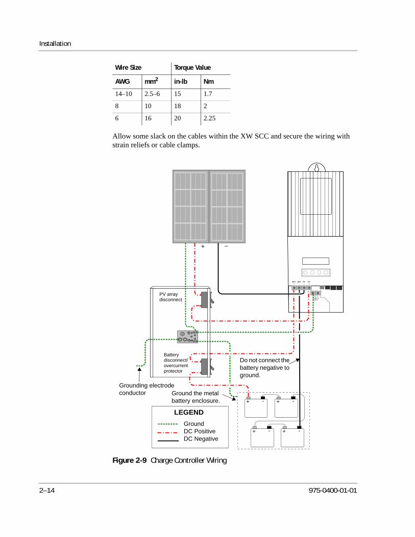
Allow some slack on the cables within the XW SCC and secure the wiring with strain reliefs or cable clamps.
Wire Size Torque Value
AWG mm2 in-lb Nm
14–10 2.5–6 15 1.7
8 10 18 2
6 16 20 2.25
Figure 2-9 Charge Controller Wiring
PV+
PV–
BAT+
BAT–
-+ -+
-+-+
LEGEND
Grounding electrode conductor
PV array disconnect
Battery disconnect/overcurrent protector
+ –
GroundDC PositiveDC Negative
Do not connect the battery negative to ground.
Ground the metal battery enclosure.
2–14 975-0400-01-01
Connecting Multiple Units
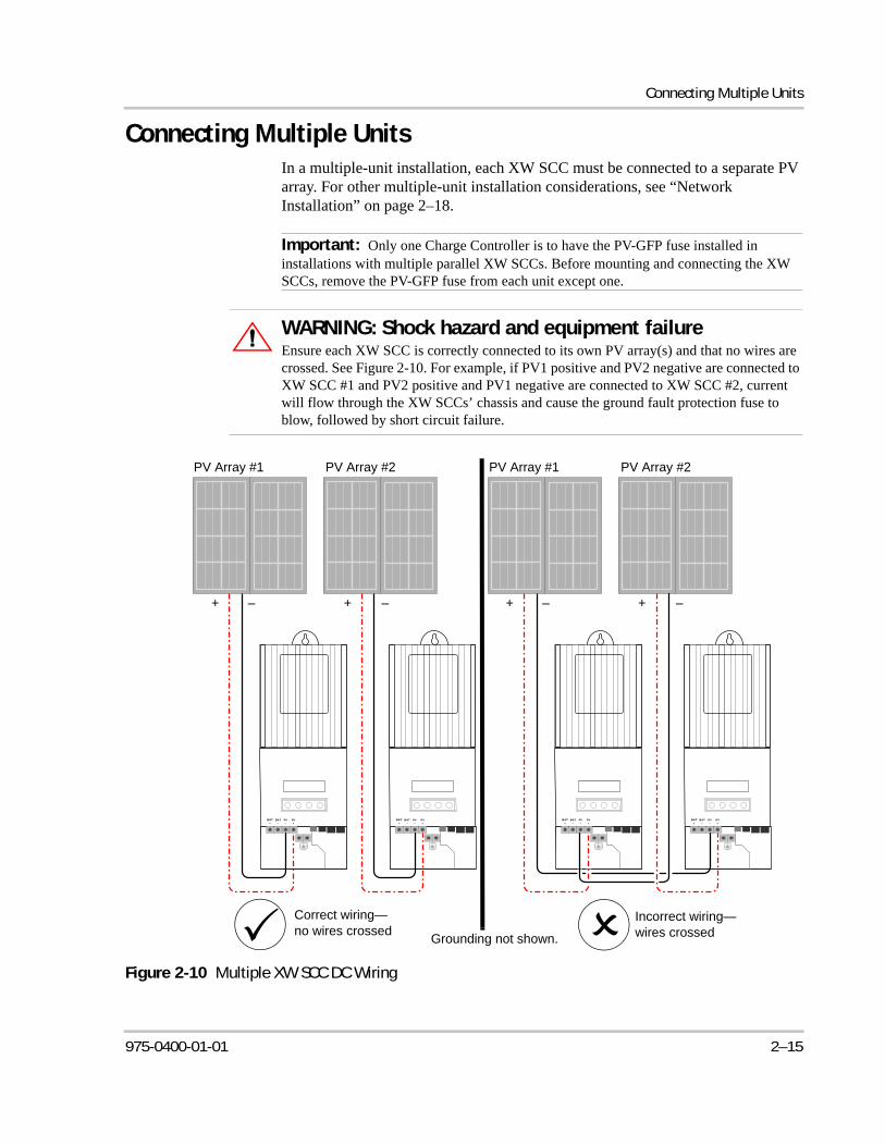
Connecting Multiple UnitsIn a multiple-unit installation, each XW SCC must be connected to a separate PV array. For other multiple-unit installation considerations, see “Network Installation” on page 2–18.
Important: Only one Charge Controller is to have the PV-GFP fuse installed in installations with multiple parallel XW SCCs. Before mounting and connecting the XW SCCs, remove the PV-GFP fuse from each unit except one.
WARNING: Shock hazard and equipment failureEnsure each XW SCC is correctly connected to its own PV array(s) and that no wires are crossed. See Figure 2-10. For example, if PV1 positive and PV2 negative are connected to XW SCC #1 and PV2 positive and PV1 negative are connected to XW SCC #2, current will flow through the XW SCCs’ chassis and cause the ground fault protection fuse to blow, followed by short circuit failure.
Figure 2-10 Multiple XW SCC DC Wiring
PV+
PV–
BAT+
BAT–
PV+
PV–
BAT+
BAT–
PV+
PV–
BAT+
BAT–
PV+
PV–
BAT+
BAT–
+ + ––
Grounding not shown.
+ + ––
Incorrect wiring—wires crossed
Correct wiring—no wires crossed
PV Array #1 PV Array #2 PV Array #1 PV Array #2
975-0400-01-01 2–15
Installation
Aux Output Connections
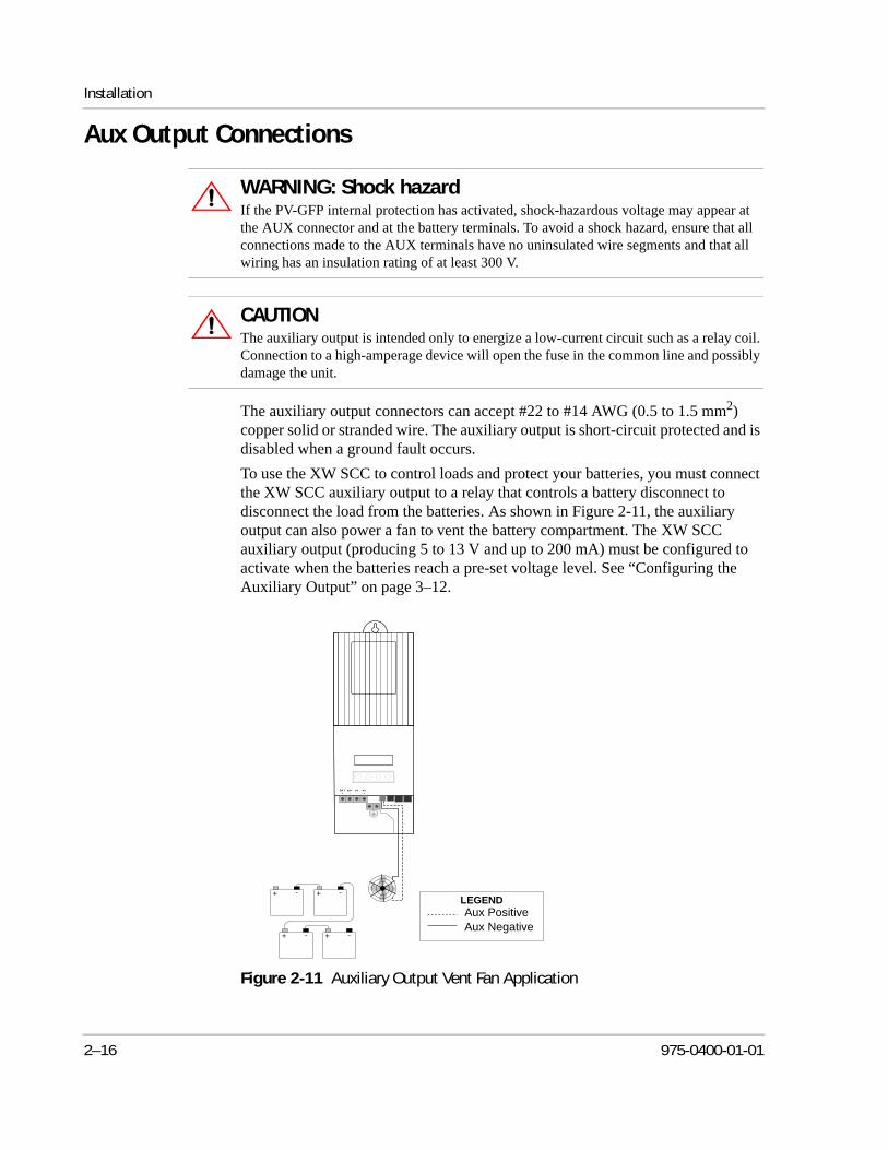
The auxiliary output connectors can accept #22 to #14 AWG (0.5 to 1.5 mm2) copper solid or stranded wire. The auxiliary output is short-circuit protected and is disabled when a ground fault occurs.
To use the XW SCC to control loads and protect your batteries, you must connect the XW SCC auxiliary output to a relay that controls a battery disconnect to disconnect the load from the batteries. As shown in Figure 2-11, the auxiliary output can also power a fan to vent the battery compartment. The XW SCC auxiliary output (producing 5 to 13 V and up to 200 mA) must be configured to activate when the batteries reach a pre-set voltage level. See “Configuring the Auxiliary Output” on page 3–12.
WARNING: Shock hazardIf the PV-GFP internal protection has activated, shock-hazardous voltage may appear at the AUX connector and at the battery terminals. To avoid a shock hazard, ensure that all connections made to the AUX terminals have no uninsulated wire segments and that all wiring has an insulation rating of at least 300 V.
CAUTIONThe auxiliary output is intended only to energize a low-current circuit such as a relay coil. Connection to a high-amperage device will open the fuse in the common line and possibly damage the unit.
Figure 2-11 Auxiliary Output Vent Fan Application
LEGEND
PV+
PV–
BAT+
BAT–
-+ -+
-+-+
Aux PositiveAux Negative
2–16 975-0400-01-01
Disconnecting the Charge Controller
Disconnecting the Charge Controller
Before disconnecting batteries and the PV array from the unit, ensure the XW SCC is not charging the batteries. If the XW SCC is charging, you can wait until the charge cycle is complete or the XW SCC displays “Low Light,” or you can put the unit into standby mode. Standby mode shuts off the XW SCC output. The XW SCC can be put into standby mode using the XW SCC Device Menu or the MPPT Setup Menu on the XW System Control Panel.
If the XW SCC is charging when the batteries are disconnected with a DC disconnect switch, an over-voltage output fault occurs due to the load on the XW SCC output being removed. After approximately 10 seconds the XW SCC LCD goes blank and the XW SCC loses power.
Normal operation resumes when the battery is reconnected.
If the unit is not charging, the charge controller simply shuts down when the batteries are disconnected. No faults are generated.
WARNING: Shock hazardEnsure both the PV array and the batteries are disconnected from the XW SCC before servicing the XW SCC or the batteries. After disconnecting the batteries, the XW SCC can appear de-energized when the PV array is still connected.
WARNING: Shock hazardAfter disconnecting power from the XW SCC, wait at least four minutes before attempting any maintenance or cleaning or working on any circuits connected to the unit. Internal capacitors remain charged for four minutes after disconnecting all sources of power.
975-0400-01-01 2–17
Installation
Network InstallationThe Xantrex XW-MPPT60-150 is a Xanbus-enabled device. Xanbus is a network communications protocol developed by Xantrex. The XW SCC is able to communicate its settings and activity to other Xanbus-enabled devices, such as the XW Series Inverter/Charger, the XW System Control Panel (SCP), XW Automatic Generator Start (XW-AGS), and other XW Solar Charge Controllers.
Xanbus connections between multiple XW SCCs allows information about each XW SCC and its associated PV array to be communicated between all of the XW SCCs in the system. Information about the entire system can be displayed on any XW SCC LCD in the system.
For example, in a two-XW SCC system, if XW SCC #1 is producing 1500 W and XW SCC #2 is producing 2000 W, both units display a total system power of 3500 W. The accumulated amp-hours and kilowatt-hours produced by both units that day is also displayed.
Networked XW SCCs also share battery temperature information if a single BTS is connected to a single unit (XW SCC or XW Inverter/Charger) in the system.
Without Xanbus connections, each XW SCC in a system will only display information specific to the unit and its associated PV array.
Network Components
A Xanbus network consists of the following components:
• Xanbus-enabled devices—these include the XW SCC, the XW Hybrid Inverter/Charger, XW-AGS, and SCP. The network can consist of up to three XW Hybrid Inverter/Chargers, two XW SCCs, one XW-AGS, and one SCP.
When only XW SCCs are installed, up to 10 units can be networked together.
• Xanbus power supply—When only XW SCCs are installed, no Xanbus power supply is required to supply network power. The XW SCCs will communicate with other XW SCCs, but the units can not supply network power to any other devices.
In systems that combine XW SCCs with other Xanbus-enabled devices, the XW Hybrid Inverter/Charger provides the required 15 Vdc/200 mA network power.
• Network cables—Each Xanbus-enabled device is connected by a standard Ethernet (CAT 5 or CAT 5e) cable, available from Xantrex or any computer supply store.
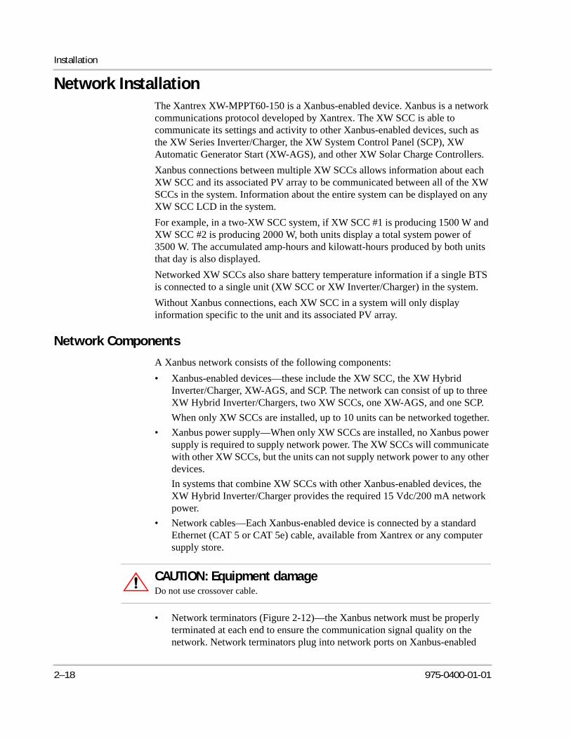
• Network terminators (Figure 2-12)—the Xanbus network must be properly terminated at each end to ensure the communication signal quality on the network. Network terminators plug into network ports on Xanbus-enabled
CAUTION: Equipment damageDo not use crossover cable.
2–18 975-0400-01-01
Network Installation
devices. The XW SCC and other Xanbus-enabled devices ship with one terminator. Depending on your network layout, this terminator may need to be inserted into another device elsewhere in the network.
Ordering Network Components
Table 2-4 provides a partial list of network components and part numbers. Cables are available in standard lengths from 3 feet (0.9 m) to 75 feet (22 m).
Call your dealer or visit the Outlet Store at www.xantrex.com to purchase cables and other network components.
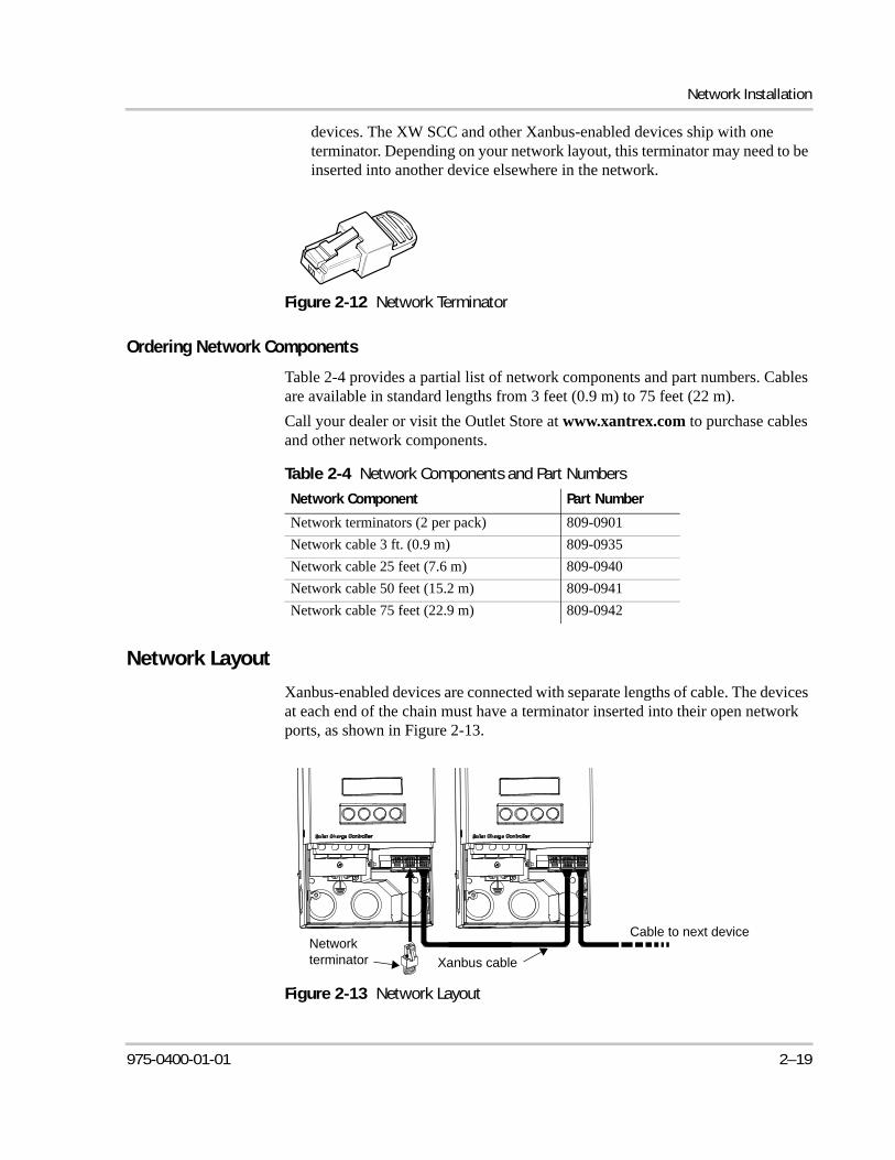
Network Layout
Xanbus-enabled devices are connected with separate lengths of cable. The devices at each end of the chain must have a terminator inserted into their open network ports, as shown in Figure 2-13.
Figure 2-12 Network Terminator
Table 2-4 Network Components and Part Numbers
Network Component Part Number
Network terminators (2 per pack) 809-0901
Network cable 3 ft. (0.9 m) 809-0935
Network cable 25 feet (7.6 m) 809-0940
Network cable 50 feet (15.2 m) 809-0941
Network cable 75 feet (22.9 m) 809-0942
Figure 2-13 Network Layout
Xanbus cable
Network terminator
Cable to next device
975-0400-01-01 2–19
Installation
Connecting Network Cable Between Multiple Units
Single knockouts on the back and bottom of the XW SCC are provided for routing the Xanbus network cables. See Figure 2-4 on page 2–6.
See Figure 2-8 on page 2–10 for the location of the XW SCC Xanbus ports.
To connect network cables between multiple units:
1. Remove the wiring compartment cover from each unit.
2. Remove a single knockout from the back or bottom of each XW SCC.
3. Connect the network cable to a Xanbus port in XW SCC #1.
4. Route the cable to XW SCC #2.
5. Connect the network cable to a Xanbus port in XW SCC #2.
6. Connect another network cable to XW SCC #2 and route the cable to the next device in the network.
7. Ensure the factory-supplied network terminators are inserted into the empty Xanbus ports in the devices at the beginning and end of the network. There should be no empty Xanbus ports in any of the XW SCCs.
:
WARNING: Shock hazardDo not route the network cables in the same conduit or panel as the DC input/output cables.
WARNING: Shock hazardBefore opening the XW SCC wiring compartment, ensure the PV array and batteries are disconnected. To reduce the risk of shock, cover the array with an opaque (dark) material.
CAUTION: Equipment damageConnect only Xanbus-enabled devices.Although the cabling and connectors used in this network system are the same as ethernet connectors, this network is not an ethernet system. Equipment damage may result from attempting to connect the XW SCC to different systems.
CAUTION: Unpredictable device behaviorDo not connect one end of the network to the other to make a ring or loop.
2–20 975-0400-01-01
Installing the Battery Temperature Sensor
Installing the Battery Temperature SensorInstalling a Battery Temperature Sensor (BTS) is recommended for optimum charging performance and extending battery life.
If a BTS is not installed and the batteries will operate in hot or cold conditions, manually adjust the temperature settings to suit the conditions. See “Configuring Battery Characteristics and Battery Charging” on page 3–5.
Only one BTS is required if multiple XW SCCs or a complete XW Power System with XW Inverter/Chargers are networked together using Xanbus. All networked XW Series devices share battery temperature information, and the BTS can be connected to a XW SCC or an XW Inverter/Charger.
See Figure 2-8 on page 2–10 for the location of the XW SCC BTS port.
Single knockouts on the back and bottom of the XW SCC are provided for routing the BTS cable. See Figure 2-4 on page 2–6.
To install the BTS:
1. Remove the XW SCC wiring compartment cover.
2. If necessary, remove a single knockout from the back or bottom of the XW SCC.
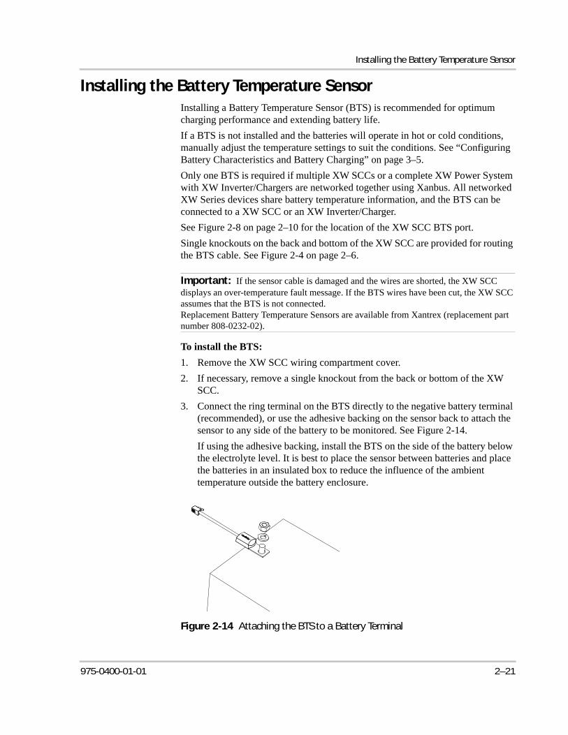
3. Connect the ring terminal on the BTS directly to the negative battery terminal (recommended), or use the adhesive backing on the sensor back to attach the sensor to any side of the battery to be monitored. See Figure 2-14.
If using the adhesive backing, install the BTS on the side of the battery below the electrolyte level. It is best to place the sensor between batteries and place the batteries in an insulated box to reduce the influence of the ambient temperature outside the battery enclosure.
Important: If the sensor cable is damaged and the wires are shorted, the XW SCC displays an over-temperature fault message. If the BTS wires have been cut, the XW SCC assumes that the BTS is not connected.Replacement Battery Temperature Sensors are available from Xantrex (replacement part number 808-0232-02).
Figure 2-14 Attaching the BTS to a Battery Terminal
975-0400-01-01 2–21

Installation
4. Pass the end of the BTS cable through a conduit hole on the XW SCC and insert the BTS plug into the BTS port. See Figure 2-15.
5. Replace the XW SCC wiring compartment cover.
Important: The BTS cable must not pass through the same conduit used for PV wiring and battery cables.
Figure 2-15 Installing the BTS
+
+
–
–+
+
–
–
xantrex
PV+
PV–
BAT +
BAT –
BTS Port Insert the BTS plug into
the XW SCC BTS port.
Attach the BTS to a battery terminal or to the side of a battery.
2–22 975-0400-01-01
Commissioning
CommissioningDuring commissioning, the XW SCC prompts you to enter important system information such as the nominal battery voltage, battery type, and battery bank capacity. Ensure you have this system information prior to commissioning.
In systems where an XW System Control Panel (SCP) is present, the SCP is intended to be the configuration interface, so the prompt screens are suppressed. See “Commissioning Units Using a System Control Panel” on page 2–27. If you prefer to configure using the prompt screens, disconnect the Xanbus cable from the XW SCC before powering up for the first time.
Configuration Screens
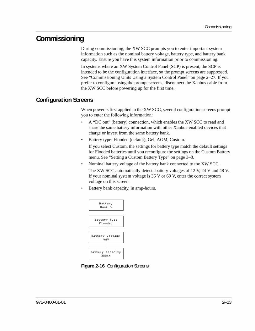
When power is first applied to the XW SCC, several configuration screens prompt you to enter the following information:
• A “DC out” (battery) connection, which enables the XW SCC to read and share the same battery information with other Xanbus-enabled devices that charge or invert from the same battery bank.
• Battery type: Flooded (default), Gel, AGM, Custom.
If you select Custom, the settings for battery type match the default settings for Flooded batteries until you reconfigure the settings on the Custom Battery menu. See “Setting a Custom Battery Type” on page 3–8.
• Nominal battery voltage of the battery bank connected to the XW SCC.
The XW SCC automatically detects battery voltages of 12 V, 24 V and 48 V. If your nominal system voltage is 36 V or 60 V, enter the correct system voltage on this screen.
• Battery bank capacity, in amp-hours.
Figure 2-16 Configuration Screens
975-0400-01-01 2–23
Installation
Commissioning a Single Unit Without a System Control Panel
To commission the XW SCC:
1. Apply battery power to the unit with a disconnect or selector switch.
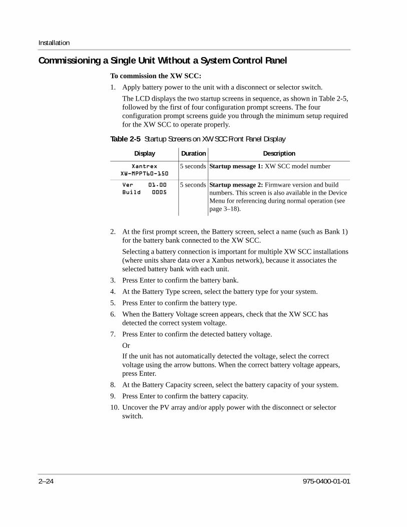
The LCD displays the two startup screens in sequence, as shown in Table 2-5, followed by the first of four configuration prompt screens. The four configuration prompt screens guide you through the minimum setup required for the XW SCC to operate properly.
2. At the first prompt screen, the Battery screen, select a name (such as Bank 1) for the battery bank connected to the XW SCC.
Selecting a battery connection is important for multiple XW SCC installations (where units share data over a Xanbus network), because it associates the selected battery bank with each unit.
3. Press Enter to confirm the battery bank.
4. At the Battery Type screen, select the battery type for your system.
5. Press Enter to confirm the battery type.
6. When the Battery Voltage screen appears, check that the XW SCC has detected the correct system voltage.
7. Press Enter to confirm the detected battery voltage.
Or
If the unit has not automatically detected the voltage, select the correct voltage using the arrow buttons. When the correct battery voltage appears, press Enter.
8. At the Battery Capacity screen, select the battery capacity of your system.
9. Press Enter to confirm the battery capacity.
10. Uncover the PV array and/or apply power with the disconnect or selector switch.
Table 2-5 Startup Screens on XW SCC Front Panel Display
Display Duration Description
5 seconds Startup message 1: XW SCC model number
5 seconds Startup message 2: Firmware version and build numbers. This screen is also available in the Device Menu for referencing during normal operation (see page 3–18).
2–24 975-0400-01-01
Commissioning
The XW SCC starts up in sleep mode and waits for a short period to determine that the input voltage is greater than the output voltage. The LCD indicates the XW SCC mode or any error conditions that may be present (see “Viewing Operating Status” on page 4–2). After the input voltage exceeds the output voltage by the required margin for 10 seconds, the unit begins operating.
Commissioning Multiple Units Without a System Control Panel
When commissioning several XW SCCs on the same Xanbus network, care must be taken to set a unique device number and the correct battery connection for each unit. The connection is important to define so that system totals and other related information are displayed accurately on each unit’s LCD.
Once the first unit is configured, you can copy that configuration to all other units by following the “Copy Config?” prompt on the LCD.
Settings that are copied from one unit to another:
• Battery Type
• Battery Amp Hour Capacity
• Max Charge Rate/Current Limit
• Charge Cycle
• Recharge Voltage
• Max Absorption Time
• Default Battery Temperature
• Nominal Battery Voltage
• DC Out Connection/Battery Bank
• Custom Battery Settings (if Custom Battery type selected):
• Equalize Support
• Equalize Voltage
• Bulk Voltage
• Absorption Voltage
• Float Voltage
• Battery Temperature Compensation
To commission multiple XW SCCs:
1. Close the DC disconnect or use a selector switch to apply battery power to all of the XW SCCs at the same time.
The LCD on each unit displays the two startup screens in sequence, as shown in Table 2-5, followed by a prompt screen for you to set the device number.
2. On all the charge controllers, set the device number to a value other than its default value of 00. No two charge controllers can have the same device number. The device number can be set to any number between 01 and 31. For the first XW SCC, 01 is recommended. If you have two charge controllers, simply set them to 01 and 02.
975-0400-01-01 2–25
Installation
After setting the device numbers, a “Copy Config?” prompt screen appears on all of the XW SCCs. The options available are “Yes” and “No”
3. On the XW SCC you set to device number 01, select “No.”
You will be prompted to enter (as described in steps 2 through 9 in “Commissioning a Single Unit Without a System Control Panel”):
• Battery connection. The default is Bank 1, and each XW SCC connected to a common battery bank must be set to the same battery connection.
• Battery voltage
• Battery type
• Battery capacity.
4. The first unit will now have the minimum configuration settings confirmed. If you want to customize other more advanced settings (such as 2-stage or 3-stage charging, or custom battery type settings), it is recommended to do that now as these settings can be automatically copied over to the other XW SCCs that are yet to be configured.
5. On the next XW SCC, which should still be displaying the “Copy Config?” prompt screen, select “Yes.”
A “Copy Setup From?” screen appears.
6. Select the device number of the first XW SCC you configured (which should be device number 01), and press Enter.
The first XW SCC’s configuration is copied to the second unit and the “Copy Config?” prompt screen disappears.
7. Uncover the PV array and/or apply power with the disconnect or selector switch.
The XW SCC starts up in sleep mode and waits for a short period to determine that the input voltage is greater than the output voltage. The LCD indicates the XW SCC mode or any error conditions that may be present (see “Viewing Operating Status” on page 4–2). After the input voltage exceeds the output voltage by the required margin for 10 seconds, the unit begins operating.
Note: If it is necessary to reset the XW SCC to factory default settings, checking that the device number has reverted to 00 will confirm the reset was successful.
Note: If you need to check the device number of the unit you previously configured, navigate to the Device Menu and view the Device Number screen. See Figure 3-2, “Complete Configuration Menus” on page 3–4. Note that the entire Device Menu is only visible when the Display Mode is set to Advanced.
2–26 975-0400-01-01
Commissioning
Commissioning Units Using a System Control Panel
In systems where an XW System Control Panel (SCP) is present, the SCP is intended to be the configuration interface. For information about SCP navigation and menus, see Appendix B, “XW System Control Panel Menus”.
Commissioning units using an SCP involves three separate procedures:
1. Setting the Device Numbers for all XW SCCs.
2. Configuring Connections and Charger Settings for the first XW SCC.
3. Copying settings from the first unit to the other XW SCC.
To set the Device Numbers for all XW SCCs:
1. Ensure the Xanbus network is connected to a Xanbus-enabled inverter to provide power to the System Control Panel.
2. Close the DC disconnect or use a selector switch to apply battery power to all of the XW SCCs at the same time. When the XW SCCs are powered up, they will detect that an SCP is already operating on the network, and be ready for configuration through the SCP. Do not apply PV power at this point.
3. From the Select Device menu on the SCP, select a XW SCC (each unit should appear as “MPPT60 00” where the 60 stands for 60A, and the 00 is its device number).
4. On the MPPT Setup menu, ensure the Advanced Settings item is displayed. If Advanced Settings are not displayed (and Basic Settings appears as the last item on the menu), press the up arrow, down arrow and Exit keys together. (See “Advanced menu” on page B–7.)
5. Select Advanced Settings, then select the Multi Unit Config menu. After entering the Multi Unit Config menu, the LCD backlight on the XW SCC to be configured will flash.
6. On the Multi Unit Config menu, select Dev Number and set it to a number other than 00. Press Enter to confirm the new device number.
The device number can be set to any number between 01 and 31. For the first XW SCC, 01 is recommended. If you have two charge controllers, simply set them to 01 and 02.
7. Press Exit until the Select Device menu is displayed.
The XW SCC now appears as MPPT60 01 on the menu.
8. Repeat steps 3 through 7 for the next XW SCC.
When you have set the device number for all XW SCCs, you can configure Connections and Charger Settings for the first XW SCC.
To configure Connections and Charger Settings for the first XW SCC:
1. On the Select Device Menu, select “MPPT60 01.”
2. Navigate to the Multi Unit Config menu and select Connections.
975-0400-01-01 2–27
Installation
On the Connections menu, you can configure PV In (PV input) and DC Conn (DC output, or the battery bank). If the system has only one battery bank, leave DC Conn at the default setting. The PV In setting allows you to differentiate which array is going to which XW SCC. This setting is used for status reporting only, not for any internal controls. Setting PV In to a non-default value is optional.
3. Press Exit twice to leave the Connections menu and Multi Unit Config menu.
4. From the Advanced Settings menu, select Charger Settings.
5. Set the Battery Type, Battery Capacity, and any other charger settings required for your system.
While in the Charger menu, ensure that the Nominal Battery Voltage is set correctly (it is shown as Batt Voltage and appears as the last item on the menu). If you select “Custom” for your Battery Type, you can further configure the Bulk, Absorption, Float and other settings for the charge cycle.
The first unit should now be configured properly for your system.
If multiple units are installed, you can now copy the first unit’s configuration over to other units.
To copy the XW SCC setup to another unit:
1. On the SCP, press Exit to leave the Advanced Settings menu and view the Select Device menu.
2. On the Select Device Menu, select the next XW SCC for configuration.
3. On the Advanced Settings menu, select Copy From, then select the XW SCC you want to copy from. You should select the unit with the device number that matches the first unit you configured.
4. Press Enter.
The settings are automatically copied from the selected unit.
5. Uncover the PV array and/or apply power with the disconnect or selector switch.
The XW SCC starts up in sleep mode and waits for a short period to determine that the input voltage is greater than the output voltage. After the input voltage exceeds the output voltage by the required margin for 10 seconds, the unit begins operating.
Note: The Copy From command will not give you any indication that it has completed its task. However, you can quickly check for yourself that the charger settings you have chosen have been copied properly by viewing some of the settings you originally configured.
2–28 975-0400-01-01
3 Configuration
Chapter 3 contains information and procedures to configure the XW Solar Charge Controller.
For information on: See:
“Configuration Menus” page 3–3
“Configuring Battery Characteristics and Battery Charging”
page 3–5
“Configuring XW SCC Input” page 3–11
“Configuring the Auxiliary Output” page 3–12
“Configuring the LCD” page 3–16
“Resetting to Factory Defaults” page 3–20
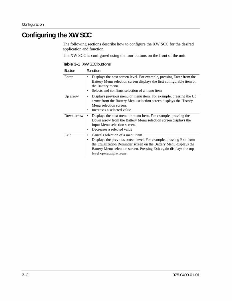
Configuration
Configuring the XW SCCThe following sections describe how to configure the XW SCC for the desired application and function.
The XW SCC is configured using the four buttons on the front of the unit.
Table 3-1 XW SCC buttons
Button Function
Enter • Displays the next screen level. For example, pressing Enter from the Battery Menu selection screen displays the first configurable item on the Battery menu.
• Selects and confirms selection of a menu item
Up arrow • Displays previous menu or menu item. For example, pressing the Up arrow from the Battery Menu selection screen displays the History Menu selection screen.
• Increases a selected value
Down arrow • Displays the next menu or menu item. For example, pressing the Down arrow from the Battery Menu selection screen displays the Input Menu selection screen.
• Decreases a selected value
Exit • Cancels selection of a menu item• Displays the previous screen level. For example, pressing Exit from
the Equalization Reminder screen on the Battery Menu displays the Battery Menu selection screen. Pressing Exit again displays the top-level operating screens.
3–2 975-0400-01-01
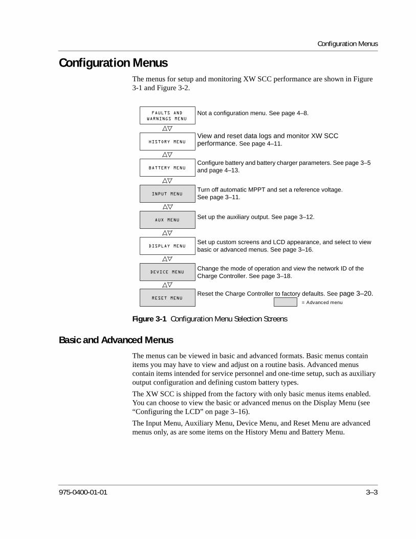
Configuration Menus
Configuration MenusThe menus for setup and monitoring XW SCC performance are shown in Figure 3-1 and Figure 3-2.
Basic and Advanced Menus
The menus can be viewed in basic and advanced formats. Basic menus contain items you may have to view and adjust on a routine basis. Advanced menus contain items intended for service personnel and one-time setup, such as auxiliary output configuration and defining custom battery types.
The XW SCC is shipped from the factory with only basic menus items enabled. You can choose to view the basic or advanced menus on the Display Menu (see “Configuring the LCD” on page 3–16).
The Input Menu, Auxiliary Menu, Device Menu, and Reset Menu are advanced menus only, as are some items on the History Menu and Battery Menu.
Figure 3-1 Configuration Menu Selection Screens
= Advanced menu
Not a configuration menu. See page 4–8.
View and reset data logs and monitor XW SCC performance. See page 4–11.
Configure battery and battery charger parameters. See page 3–5 and page 4–13.
Turn off automatic MPPT and set a reference voltage. See page 3–11.
Set up the auxiliary output. See page 3–12.
Set up custom screens and LCD appearance, and select to view basic or advanced menus. See page 3–16.
Reset the Charge Controller to factory defaults. See page 3–20.
Change the mode of operation and view the network ID of the Charge Controller. See page 3–18.
975-0400-01-01 3–3
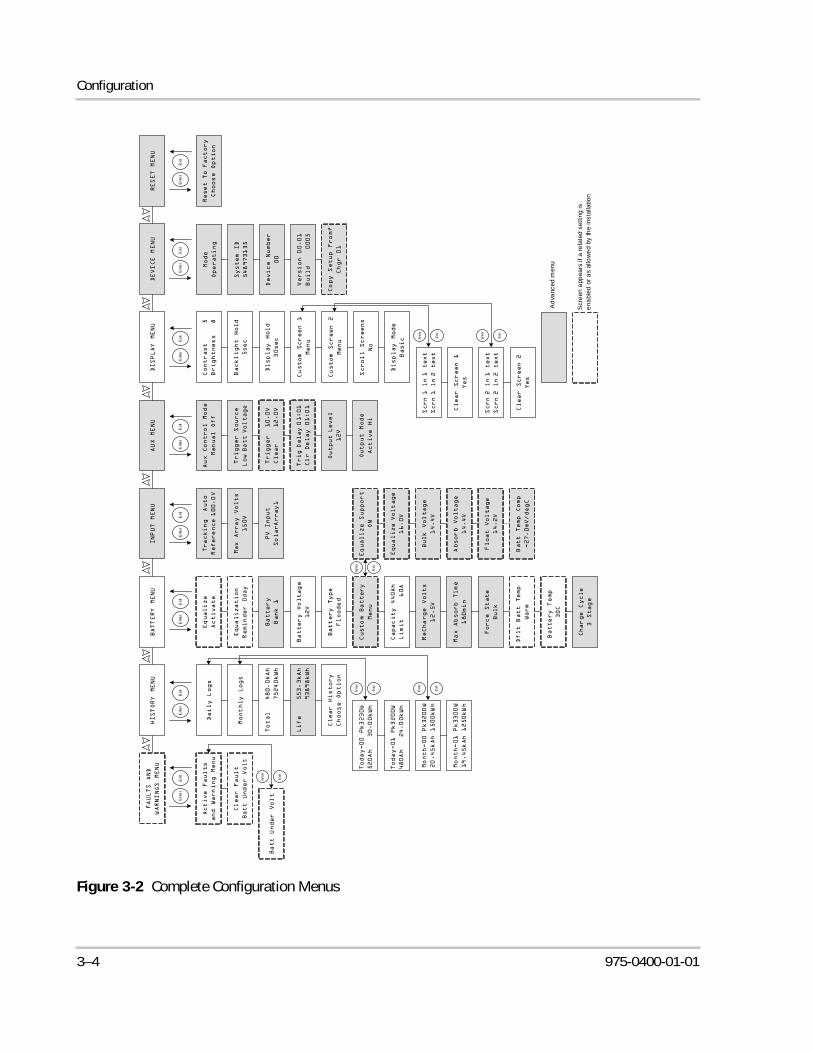
Configuration
Figure 3-2 Complete Configuration Menus
Ad
vanc
ed m
enu
Ent
er
Exi
tE
nte
rE
xit
Ent
er
Exi
tE
nte
rE
xit
Ent
er
Exi
tE
nte
rE
xit
Ent
er
Exi
t
Exi
t
En
ter
Exi
t
En
ter
Ent
er
Exi
t
Exi
t
En
ter
Exi
t
En
ter
Exi
t
En
ter
Exi
t
En
ter
Scr
een
app
ears
if a
re
late
d se
ttin
g is
e
nabl
ed o
r a
s al
low
ed
by th
e in
stal
latio
n
3–4 975-0400-01-01
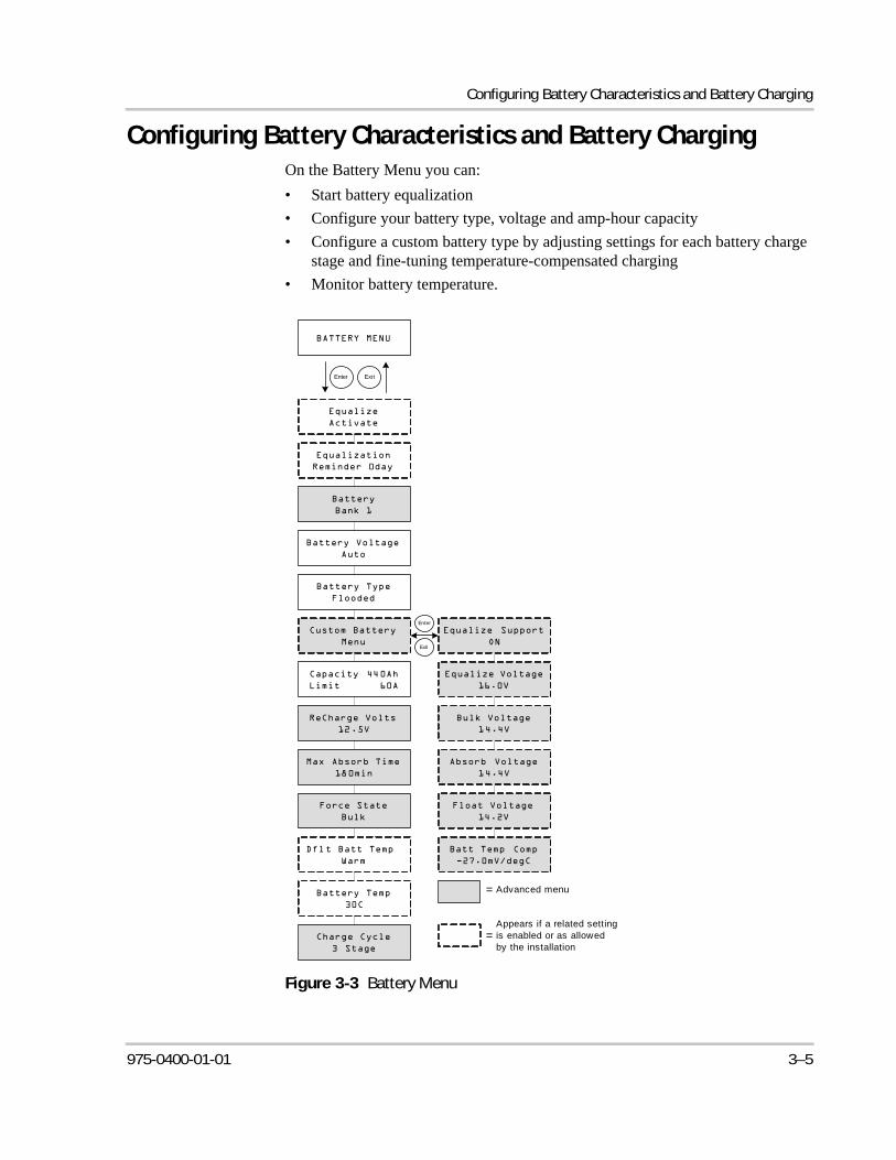
Configuring Battery Characteristics and Battery Charging
Configuring Battery Characteristics and Battery ChargingOn the Battery Menu you can:
• Start battery equalization
• Configure your battery type, voltage and amp-hour capacity
• Configure a custom battery type by adjusting settings for each battery charge stage and fine-tuning temperature-compensated charging
• Monitor battery temperature.
Figure 3-3 Battery Menu
Advanced menu=
Enter Exit
Exit
Enter
Appears if a related setting is enabled or as allowed by the installation
=
975-0400-01-01 3–5
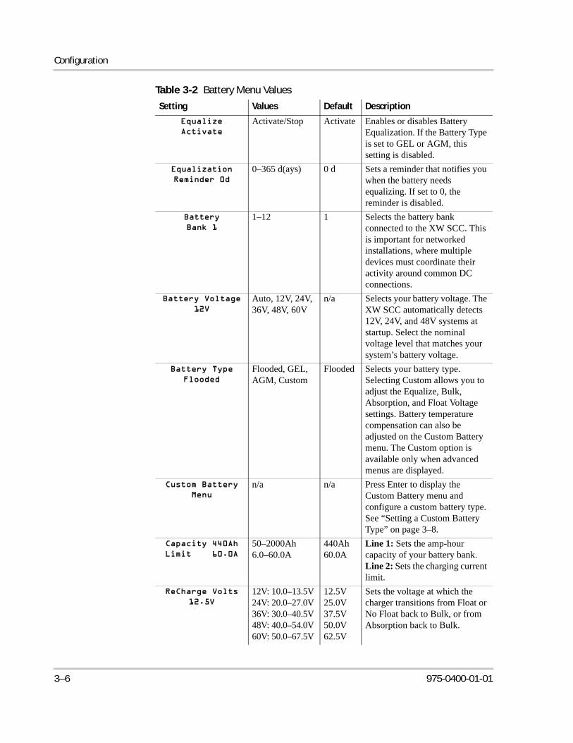
Configuration
Table 3-2 Battery Menu Values
Setting Values Default Description
Activate/Stop Activate Enables or disables Battery Equalization. If the Battery Type is set to GEL or AGM, this setting is disabled.
0–365 d(ays) 0 d Sets a reminder that notifies you when the battery needs equalizing. If set to 0, the reminder is disabled.
1–12 1 Selects the battery bank connected to the XW SCC. This is important for networked installations, where multiple devices must coordinate their activity around common DC connections.
Auto, 12V, 24V, 36V, 48V, 60V
n/a Selects your battery voltage. The XW SCC automatically detects 12V, 24V, and 48V systems at startup. Select the nominal voltage level that matches your system’s battery voltage.
Flooded, GEL, AGM, Custom
Flooded Selects your battery type. Selecting Custom allows you to adjust the Equalize, Bulk, Absorption, and Float Voltage settings. Battery temperature compensation can also be adjusted on the Custom Battery menu. The Custom option is available only when advanced menus are displayed.
n/a n/a Press Enter to display the Custom Battery menu and configure a custom battery type. See “Setting a Custom Battery Type” on page 3–8.
50–2000Ah6.0–60.0A
440Ah60.0A
Line 1: Sets the amp-hour capacity of your battery bank.Line 2: Sets the charging current limit.
12V: 10.0–13.5V24V: 20.0–27.0V36V: 30.0–40.5V48V: 40.0–54.0V60V: 50.0–67.5V
12.5V25.0V37.5V50.0V62.5V
Sets the voltage at which the charger transitions from Float or No Float back to Bulk, or from Absorption back to Bulk.
3–6 975-0400-01-01
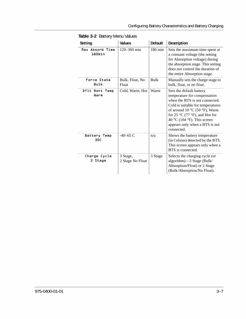
Configuring Battery Characteristics and Battery Charging
120–360 min 180 min Sets the maximum time spent at a constant voltage (the setting for Absorption voltage) during the absorption stage. This setting does not control the duration of the entire Absorption stage.
Bulk, Float, No Float
Bulk Manually sets the charge stage to bulk, float, or no float.
Cold, Warm, Hot Warm Sets the default battery temperature for compensation when the BTS is not connected. Cold is suitable for temperatures of around 10 °C (50 °F), Warm for 25 °C (77 °F), and Hot for 40 °C (104 °F). This screen appears only when a BTS is not connected.
-40–65 C n/a Shows the battery temperature (in Celsius) detected by the BTS. This screen appears only when a BTS is connected.
3 Stage, 2 Stage No Float
3 Stage Selects the charging cycle (or algorithm)—3 Stage (Bulk/Absorption/Float) or 2 Stage (Bulk/Absorption/No Float).
Table 3-2 Battery Menu Values
Setting Values Default Description
975-0400-01-01 3–7
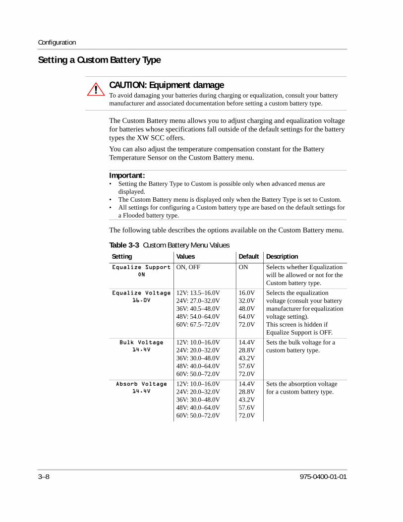
Configuration
Setting a Custom Battery Type
The Custom Battery menu allows you to adjust charging and equalization voltage for batteries whose specifications fall outside of the default settings for the battery types the XW SCC offers.
You can also adjust the temperature compensation constant for the Battery Temperature Sensor on the Custom Battery menu.
The following table describes the options available on the Custom Battery menu.
CAUTION: Equipment damageTo avoid damaging your batteries during charging or equalization, consult your battery manufacturer and associated documentation before setting a custom battery type.
Important:• Setting the Battery Type to Custom is possible only when advanced menus are
displayed.• The Custom Battery menu is displayed only when the Battery Type is set to Custom.• All settings for configuring a Custom battery type are based on the default settings for
a Flooded battery type.
Table 3-3 Custom Battery Menu Values
Setting Values Default Description
ON, OFF ON Selects whether Equalization will be allowed or not for the Custom battery type.
12V: 13.5–16.0V24V: 27.0–32.0V36V: 40.5–48.0V48V: 54.0–64.0V60V: 67.5–72.0V
16.0V32.0V48.0V64.0V72.0V
Selects the equalization voltage (consult your battery manufacturer for equalization voltage setting).This screen is hidden if Equalize Support is OFF.
12V: 10.0–16.0V24V: 20.0–32.0V36V: 30.0–48.0V48V: 40.0–64.0V60V: 50.0–72.0V
14.4V28.8V43.2V57.6V72.0V
Sets the bulk voltage for a custom battery type.
12V: 10.0–16.0V24V: 20.0–32.0V36V: 30.0–48.0V48V: 40.0–64.0V60V: 50.0–72.0V
14.4V28.8V43.2V57.6V72.0V
Sets the absorption voltage for a custom battery type.
3–8 975-0400-01-01
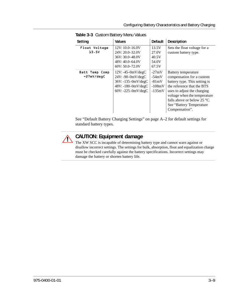
Configuring Battery Characteristics and Battery Charging
See “Default Battery Charging Settings” on page A–2 for default settings for standard battery types.
12V: 10.0–16.0V24V: 20.0–32.0V36V: 30.0–48.0V48V: 40.0–64.0V60V: 50.0–72.0V
13.5V27.0V40.5V54.0V67.5V
Sets the float voltage for a custom battery type.
12V: -45–0mV/degC24V: -90–0mV/degC36V: -135–0mV/degC48V: -180–0mV/degC60V: -225–0mV/degC
-27mV-54mV-81mV-108mV-135mV
Battery temperature compensation for a custom battery type. This setting is the reference that the BTS uses to adjust the charging voltage when the temperature falls above or below 25 °C. See “Battery Temperature Compensation”.
Table 3-3 Custom Battery Menu Values
Setting Values Default Description
CAUTION: Equipment damageThe XW SCC is incapable of determining battery type and cannot warn against or disallow incorrect settings. The settings for bulk, absorption, float and equalization charge must be checked carefully against the battery specifications. Incorrect settings may damage the battery or shorten battery life.
975-0400-01-01 3–9
Configuration
Battery Temperature Compensation
When battery charging voltages are compensated based on temperature, the charge voltage will vary depending on the temperature around the batteries.
Temperature compensation can be accomplished automatically by using a BTS. The BTS attaches directly to the side of one of the batteries in the bank and provides precise battery temperature information.
See “Installing the Battery Temperature Sensor” on page 2–21 for detailed instructions on how and where to install the BTS.
If a BTS is installed, the charge controlling process will be automatically adjusted for the battery temperature. The XW SCC uses the following coefficients to adjust the charging voltage:
• Flooded Lead-Acid and Gel-Type Batteries (12 V nominal):-27 mV per degree Celsius
• Absorbed Glass Mat (AGM)-Type Batteries (12 V nominal): -21 mV per degree Celsius
If using a BTS, when the battery temperature drops below 77 °F (25 °C), the regulation voltage setting automatically increases. When the temperature rises above 77 °F (25 °C) the regulation battery voltage setting automatically decreases. The temperature range where compensation is applied is between 0 °C, and 50 °C. Outside of this temperature range, the compensation value is clamped at the corresponding value for either 0 °C or 50 °C.
If a BTS is not installed, you can configure the XW SCC to use one of three temperature compensated charge settings:
• Cold—50 °F (10 °C)
• Warm—77 °F (25 °C)
• Hot—104 °F (40 °C)
If significant seasonal variations are common in your area, you will have to change the settings during the year to ensure optimal battery charging.
3–10 975-0400-01-01
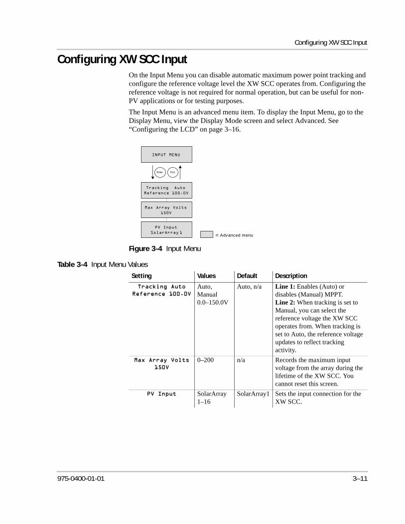
Configuring XW SCC Input
Configuring XW SCC InputOn the Input Menu you can disable automatic maximum power point tracking and configure the reference voltage level the XW SCC operates from. Configuring the reference voltage is not required for normal operation, but can be useful for non-PV applications or for testing purposes.
The Input Menu is an advanced menu item. To display the Input Menu, go to the Display Menu, view the Display Mode screen and select Advanced. See “Configuring the LCD” on page 3–16.
Figure 3-4 Input Menu
Table 3-4 Input Menu Values
Setting Values Default Description
Auto, Manual0.0–150.0V
Auto, n/a Line 1: Enables (Auto) or disables (Manual) MPPT.Line 2: When tracking is set to Manual, you can select the reference voltage the XW SCC operates from. When tracking is set to Auto, the reference voltage updates to reflect tracking activity.
0–200 n/a Records the maximum input voltage from the array during the lifetime of the XW SCC. You cannot reset this screen.
SolarArray1–16
SolarArray1 Sets the input connection for the XW SCC.
Advanced menu=
Enter Exit
975-0400-01-01 3–11
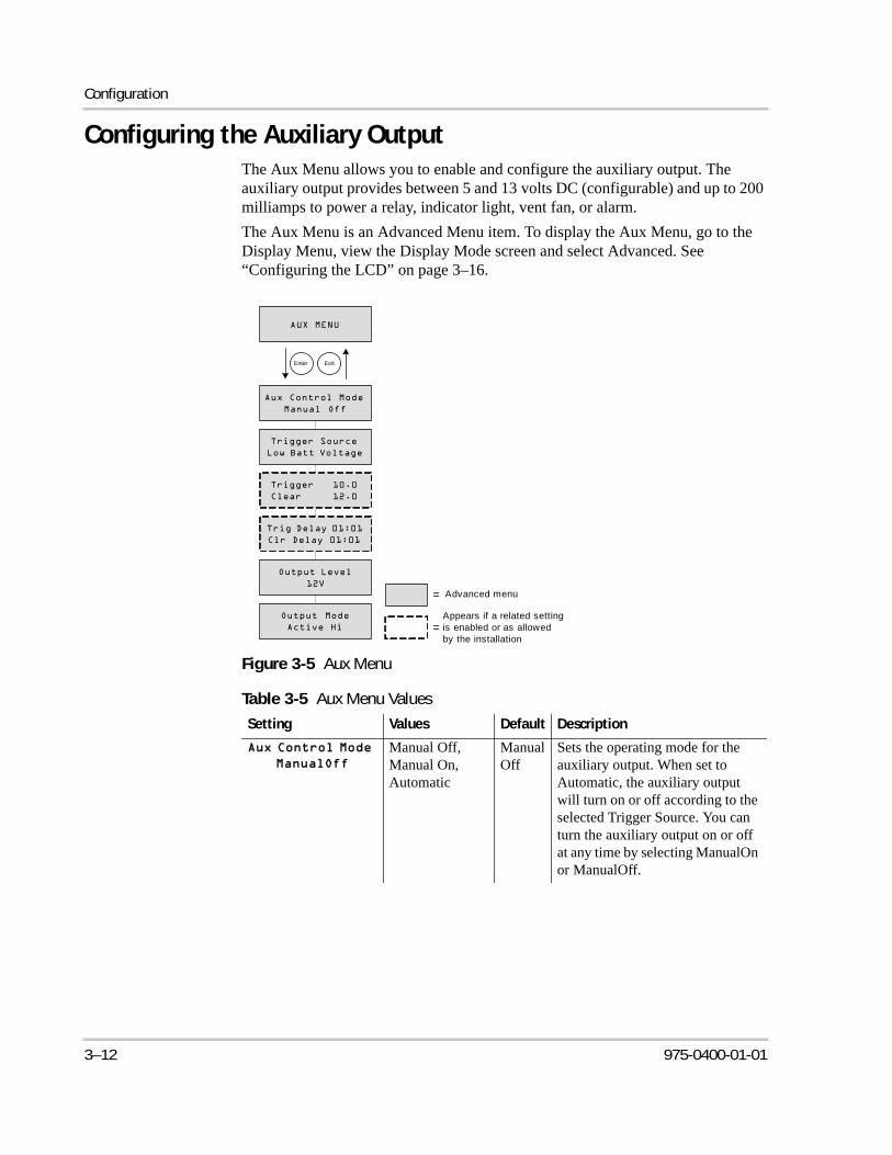
Configuration
Configuring the Auxiliary OutputThe Aux Menu allows you to enable and configure the auxiliary output. The auxiliary output provides between 5 and 13 volts DC (configurable) and up to 200 milliamps to power a relay, indicator light, vent fan, or alarm.
The Aux Menu is an Advanced Menu item. To display the Aux Menu, go to the Display Menu, view the Display Mode screen and select Advanced. See “Configuring the LCD” on page 3–16.
Figure 3-5 Aux Menu
Table 3-5 Aux Menu Values
Setting Values Default Description
Manual Off, Manual On, Automatic
ManualOff
Sets the operating mode for the auxiliary output. When set to Automatic, the auxiliary output will turn on or off according to the selected Trigger Source. You can turn the auxiliary output on or off at any time by selecting ManualOn or ManualOff.
Advanced menu=
Enter Exit
Appears if a related setting is enabled or as allowed by the installation
=
3–12 975-0400-01-01
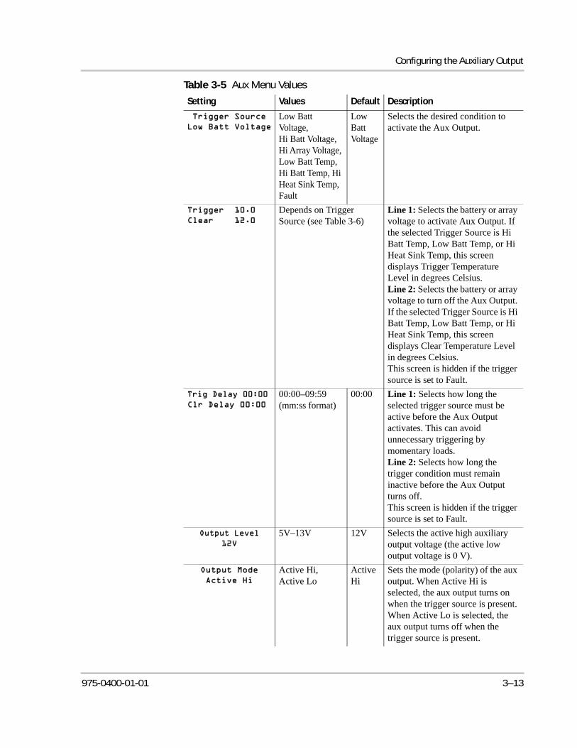
Configuring the Auxiliary Output
Low Batt Voltage,Hi Batt Voltage, Hi Array Voltage, Low Batt Temp,Hi Batt Temp, Hi Heat Sink Temp, Fault
Low Batt Voltage
Selects the desired condition to activate the Aux Output.
Depends on Trigger Source (see Table 3-6)
Line 1: Selects the battery or array voltage to activate Aux Output. If the selected Trigger Source is Hi Batt Temp, Low Batt Temp, or Hi Heat Sink Temp, this screen displays Trigger Temperature Level in degrees Celsius.Line 2: Selects the battery or array voltage to turn off the Aux Output. If the selected Trigger Source is Hi Batt Temp, Low Batt Temp, or Hi Heat Sink Temp, this screen displays Clear Temperature Level in degrees Celsius.This screen is hidden if the trigger source is set to Fault.
00:00–09:59(mm:ss format)
00:00 Line 1: Selects how long the selected trigger source must be active before the Aux Output activates. This can avoid unnecessary triggering by momentary loads.Line 2: Selects how long the trigger condition must remain inactive before the Aux Output turns off.This screen is hidden if the trigger source is set to Fault.
5V–13V 12V Selects the active high auxiliary output voltage (the active low output voltage is 0 V).
Active Hi,Active Lo
Active Hi
Sets the mode (polarity) of the aux output. When Active Hi is selected, the aux output turns on when the trigger source is present. When Active Lo is selected, the aux output turns off when the trigger source is present.
Table 3-5 Aux Menu Values
Setting Values Default Description
975-0400-01-01 3–13
Configuration
Trigger Source Descriptions
Low Batt Voltage Activates the auxiliary output when the battery voltage falls below the trigger setting for the trigger delay time. Deactivates the auxiliary output when the battery voltage rises above the clear setting for the clear delay time. Use this setting if you want the auxiliary output to control a relay to disconnect loads from a battery that is nearly discharged, or to activate a low-battery-voltage alarm such as a buzzer or light.
Hi Batt Voltage Activates the auxiliary output when the battery voltage rises above the trigger setting for the trigger delay time. Deactivates the auxiliary output when the battery voltage falls below the clear setting for the clear delay time. This setting is useful for:
• installations that have another external charging source such as a wind generator or hydro generator connected directly to the batteries. The XW SCC auxiliary output can control a relay to disconnect the external charging source from the battery when the battery is in danger of being overcharged, or control a relay to turn on a diversion load.
• activating a high-battery-voltage alarm such as a buzzer or light.
• activating a vent fan to disperse hydrogen from the battery compartment when the batteries reach their gassing voltage.
Hi Array Voltage Activates the auxiliary output when the PV array voltage rises above the trigger setting for the trigger delay time. Deactivates the auxiliary output when the PV array voltage falls below the clear setting for the clear delay time. Use this setting if you want the auxiliary output to control a series latching relay to disconnect the PV array from the XW SCC or trigger an alarm when the PV array voltage exceeds the trigger setting (the XW SCC maximum operating voltage is 140 Vdc).
You can also use the Hi Array Voltage trigger to control a relay to turn on a night light. Set the Trigger Level to your nominal battery voltage and the Output Mode to Active Lo. This will energize the relay and turn on the light whenever the array voltage is insufficient to charge the battery bank.
Low Batt Temp Activates the auxiliary output when the battery temperature falls below the trigger setting for the trigger delay time. Deactivates the auxiliary output when the battery temperature rises above the clear setting for the clear delay time. Battery temperature is measured with a battery temperature sensor. Do not use this setting if a battery temperature sensor is not installed. With this setting, the auxiliary output can turn on an indicator alarm if the batteries are too cold. A battery with frozen electrolyte will not accept a charge.
Important: If the selected trigger source is Low Batt Voltage or Hi Batt Voltage, changing the nominal battery voltage setting will reset the Trigger Voltage Level and Clear Voltage Level settings to their default values.
3–14 975-0400-01-01
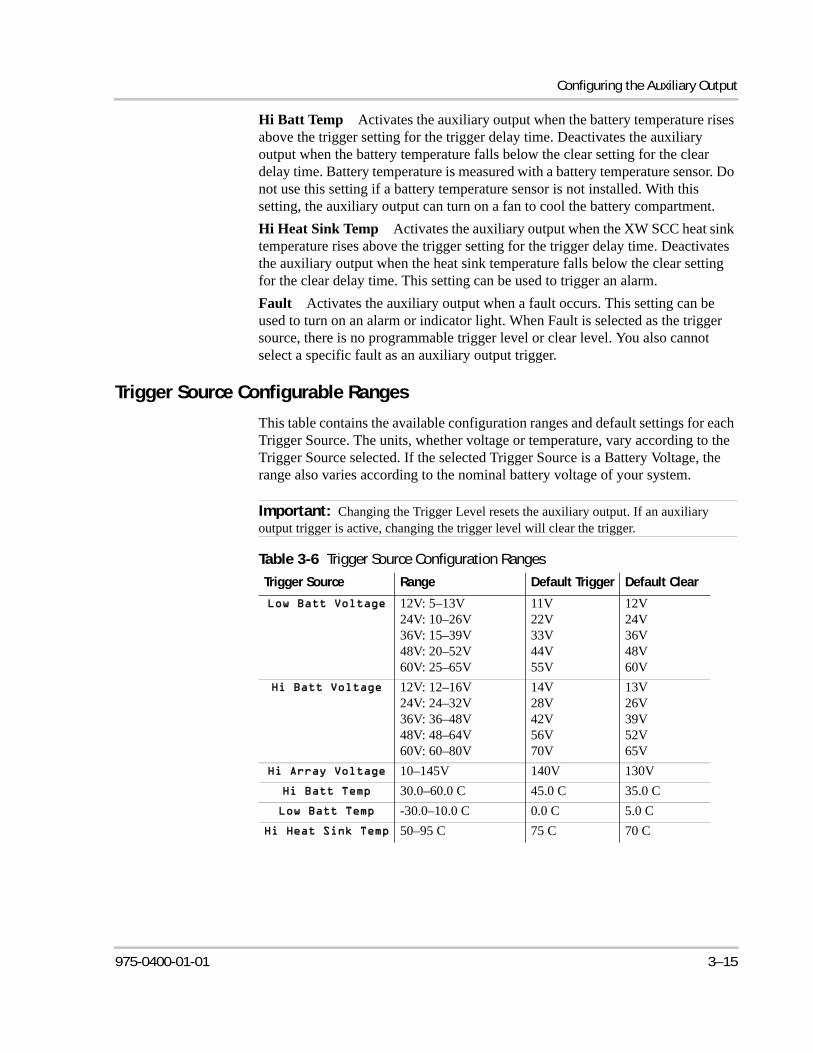
Configuring the Auxiliary Output
Hi Batt Temp Activates the auxiliary output when the battery temperature rises above the trigger setting for the trigger delay time. Deactivates the auxiliary output when the battery temperature falls below the clear setting for the clear delay time. Battery temperature is measured with a battery temperature sensor. Do not use this setting if a battery temperature sensor is not installed. With this setting, the auxiliary output can turn on a fan to cool the battery compartment.
Hi Heat Sink Temp Activates the auxiliary output when the XW SCC heat sink temperature rises above the trigger setting for the trigger delay time. Deactivates the auxiliary output when the heat sink temperature falls below the clear setting for the clear delay time. This setting can be used to trigger an alarm.
Fault Activates the auxiliary output when a fault occurs. This setting can be used to turn on an alarm or indicator light. When Fault is selected as the trigger source, there is no programmable trigger level or clear level. You also cannot select a specific fault as an auxiliary output trigger.
Trigger Source Configurable Ranges
This table contains the available configuration ranges and default settings for each Trigger Source. The units, whether voltage or temperature, vary according to the Trigger Source selected. If the selected Trigger Source is a Battery Voltage, the range also varies according to the nominal battery voltage of your system.
Important: Changing the Trigger Level resets the auxiliary output. If an auxiliary output trigger is active, changing the trigger level will clear the trigger.
Table 3-6 Trigger Source Configuration Ranges
Trigger Source Range Default Trigger Default Clear
12V: 5–13V24V: 10–26V36V: 15–39V48V: 20–52V60V: 25–65V
11V22V33V44V55V
12V24V36V48V60V
12V: 12–16V24V: 24–32V36V: 36–48V48V: 48–64V60V: 60–80V
14V28V42V56V70V
13V26V39V52V65V
10–145V 140V 130V
30.0–60.0 C 45.0 C 35.0 C
-30.0–10.0 C 0.0 C 5.0 C
50–95 C 75 C 70 C
975-0400-01-01 3–15
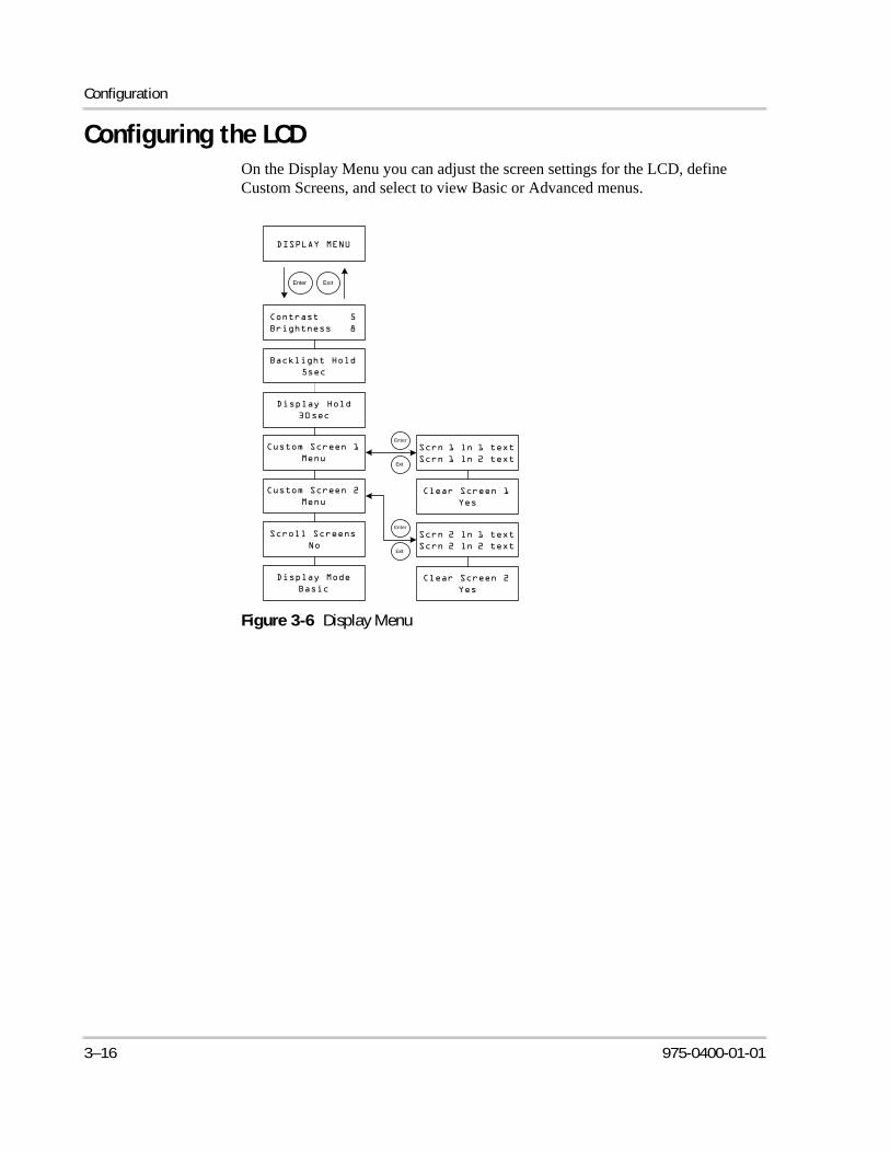
Configuration
Configuring the LCDOn the Display Menu you can adjust the screen settings for the LCD, define Custom Screens, and select to view Basic or Advanced menus.
Figure 3-6 Display Menu
Enter Exit
Exit
Enter
Exit
Enter
3–16 975-0400-01-01
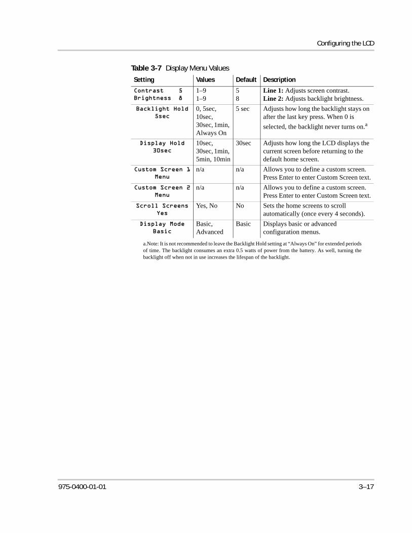
Configuring the LCD
Table 3-7 Display Menu Values
Setting Values Default Description
1–91–9
58
Line 1: Adjusts screen contrast.Line 2: Adjusts backlight brightness.
0, 5sec, 10sec, 30sec, 1min, Always On
5 sec Adjusts how long the backlight stays on after the last key press. When 0 is
selected, the backlight never turns on.a
a.Note: It is not recommended to leave the Backlight Hold setting at “Always On” for extended periodsof time. The backlight consumes an extra 0.5 watts of power from the battery. As well, turning thebacklight off when not in use increases the lifespan of the backlight.
10sec, 30sec, 1min, 5min, 10min
30sec Adjusts how long the LCD displays the current screen before returning to the default home screen.
n/a n/a Allows you to define a custom screen. Press Enter to enter Custom Screen text.
n/a n/a Allows you to define a custom screen. Press Enter to enter Custom Screen text.
Yes, No No Sets the home screens to scroll automatically (once every 4 seconds).
Basic, Advanced
Basic Displays basic or advanced configuration menus.
975-0400-01-01 3–17
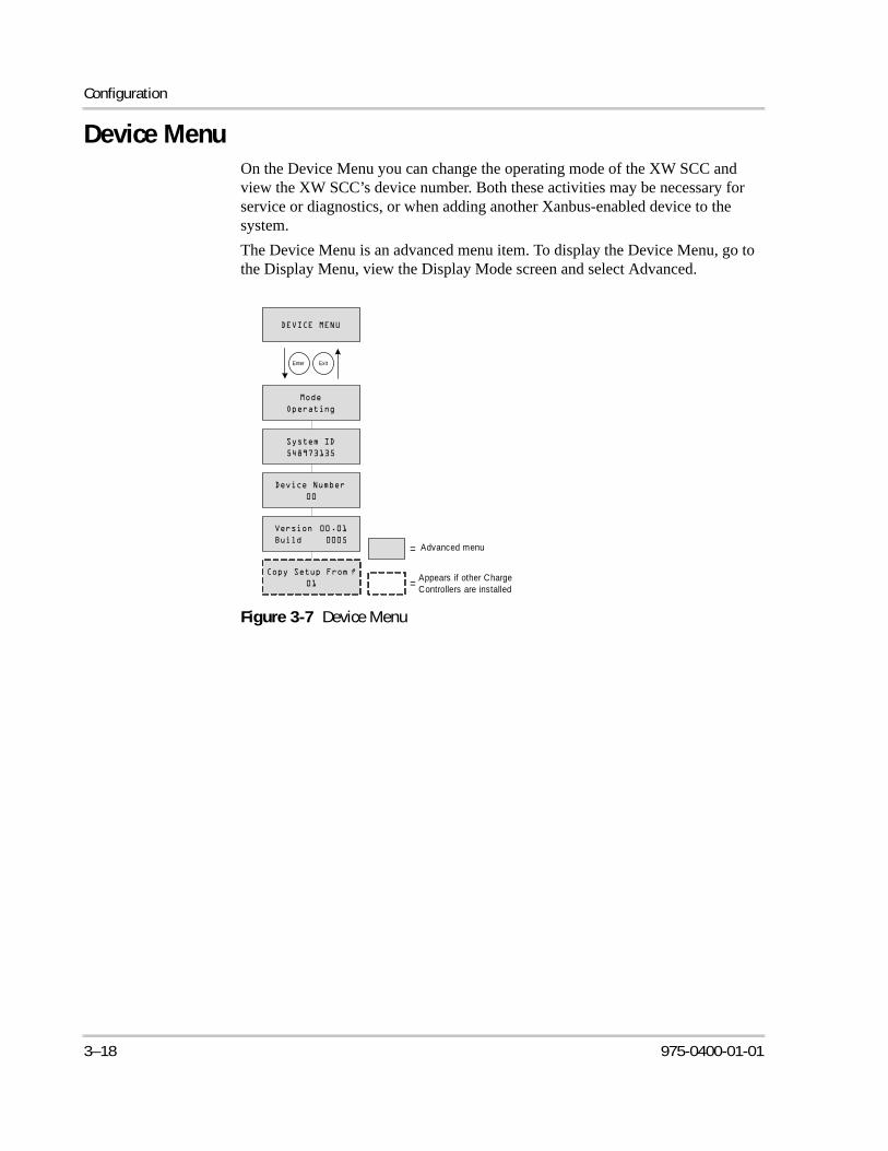
Configuration
Device MenuOn the Device Menu you can change the operating mode of the XW SCC and view the XW SCC’s device number. Both these activities may be necessary for service or diagnostics, or when adding another Xanbus-enabled device to the system.
The Device Menu is an advanced menu item. To display the Device Menu, go to the Display Menu, view the Display Mode screen and select Advanced.
Figure 3-7 Device Menu
Enter Exit
Advanced menu=
Appears if other Charge
Controllers are installed=
3–18 975-0400-01-01
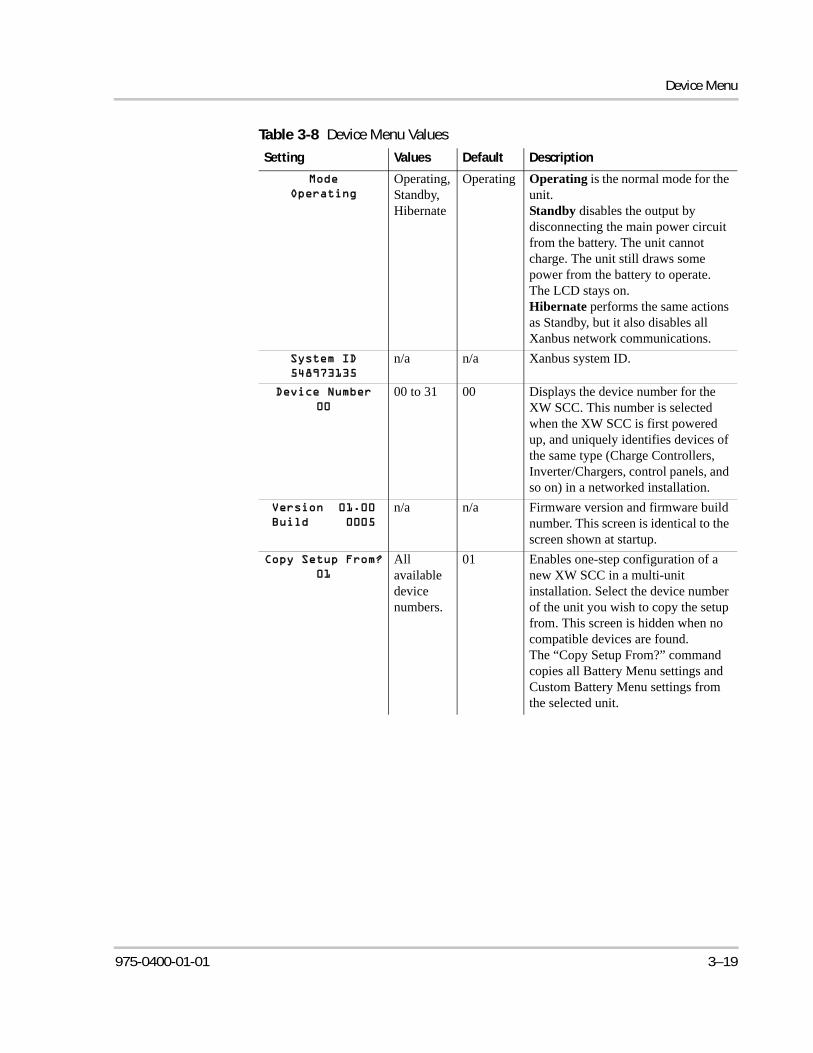
Device Menu
Table 3-8 Device Menu Values
Setting Values Default Description
Operating, Standby, Hibernate
Operating Operating is the normal mode for the unit. Standby disables the output by disconnecting the main power circuit from the battery. The unit cannot charge. The unit still draws some power from the battery to operate. The LCD stays on.Hibernate performs the same actions as Standby, but it also disables all Xanbus network communications.
n/a n/a Xanbus system ID.
00 to 31 00 Displays the device number for the XW SCC. This number is selected when the XW SCC is first powered up, and uniquely identifies devices of the same type (Charge Controllers, Inverter/Chargers, control panels, and so on) in a networked installation.
n/a n/a Firmware version and firmware build number. This screen is identical to the screen shown at startup.
All available device numbers.
01 Enables one-step configuration of a new XW SCC in a multi-unit installation. Select the device number of the unit you wish to copy the setup from. This screen is hidden when no compatible devices are found.The “Copy Setup From?” command copies all Battery Menu settings and Custom Battery Menu settings from the selected unit.
975-0400-01-01 3–19
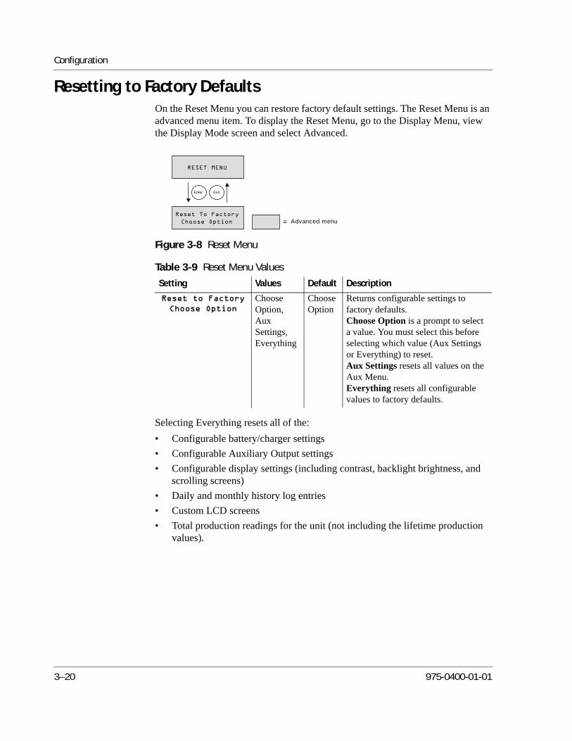
Configuration
Resetting to Factory DefaultsOn the Reset Menu you can restore factory default settings. The Reset Menu is an advanced menu item. To display the Reset Menu, go to the Display Menu, view the Display Mode screen and select Advanced.
Selecting Everything resets all of the:
• Configurable battery/charger settings
• Configurable Auxiliary Output settings
• Configurable display settings (including contrast, backlight brightness, and scrolling screens)
• Daily and monthly history log entries
• Custom LCD screens
• Total production readings for the unit (not including the lifetime production values).
Figure 3-8 Reset Menu
Table 3-9 Reset Menu Values
Setting Values Default Description
Choose Option, Aux Settings, Everything
Choose Option
Returns configurable settings to factory defaults.Choose Option is a prompt to select a value. You must select this before selecting which value (Aux Settings or Everything) to reset.Aux Settings resets all values on the Aux Menu.Everything resets all configurable values to factory defaults.
Enter Exit
Advanced menu=
3–20 975-0400-01-01
4 Operation
Chapter 4 contains information about the operation of the XW Solar Charge Controller.
For Information on: See:
“Viewing Operating Status” page 4–2
“Monitoring XW SCC Operation” page 4–7
“Battery Equalization” page 4–13
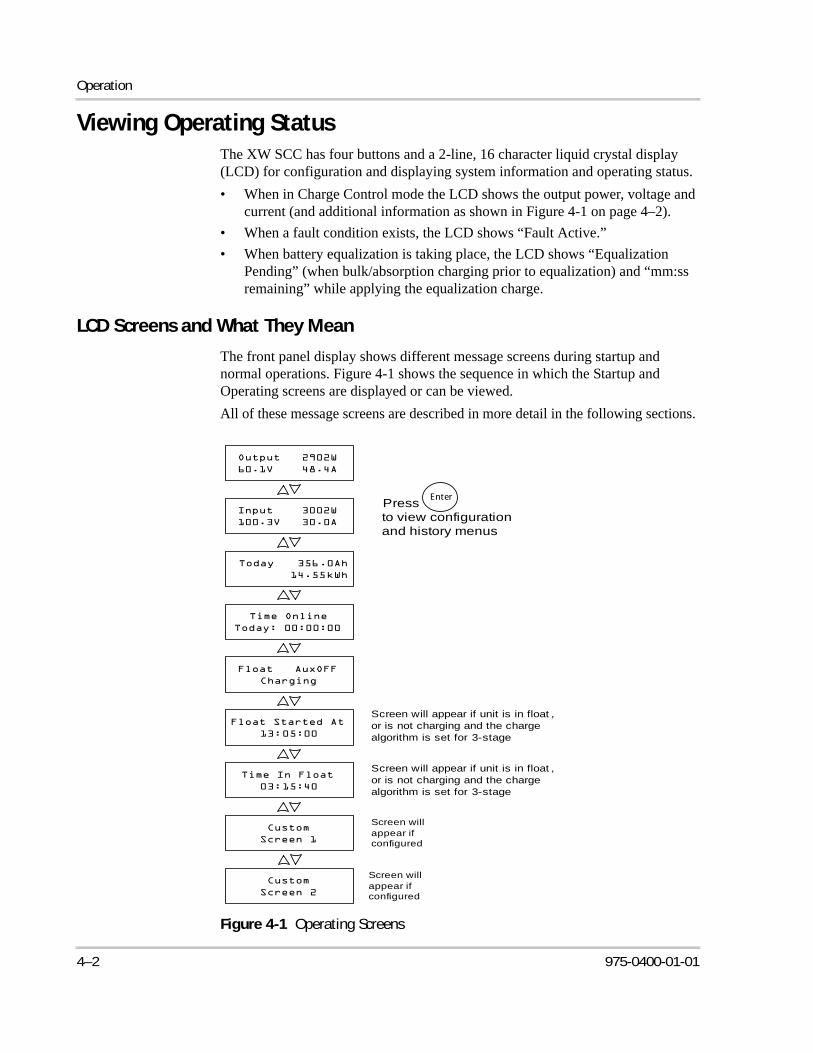
Operation
Viewing Operating StatusThe XW SCC has four buttons and a 2-line, 16 character liquid crystal display (LCD) for configuration and displaying system information and operating status.
• When in Charge Control mode the LCD shows the output power, voltage and current (and additional information as shown in Figure 4-1 on page 4–2).
• When a fault condition exists, the LCD shows “Fault Active.”
• When battery equalization is taking place, the LCD shows “Equalization Pending” (when bulk/absorption charging prior to equalization) and “mm:ss remaining” while applying the equalization charge.
LCD Screens and What They Mean
The front panel display shows different message screens during startup and normal operations. Figure 4-1 shows the sequence in which the Startup and Operating screens are displayed or can be viewed.
All of these message screens are described in more detail in the following sections.
Figure 4-1 Operating Screens
Screen will appear if configured
Screen will appear if configured
Enter
to view configuration and history menus
Press
Screen will appear if unit is in float , or is not charging and the charge algorithm is set for 3-stage
Screen will appear if unit is in float , or is not charging and the charge algorithm is set for 3-stage
4–2 975-0400-01-01
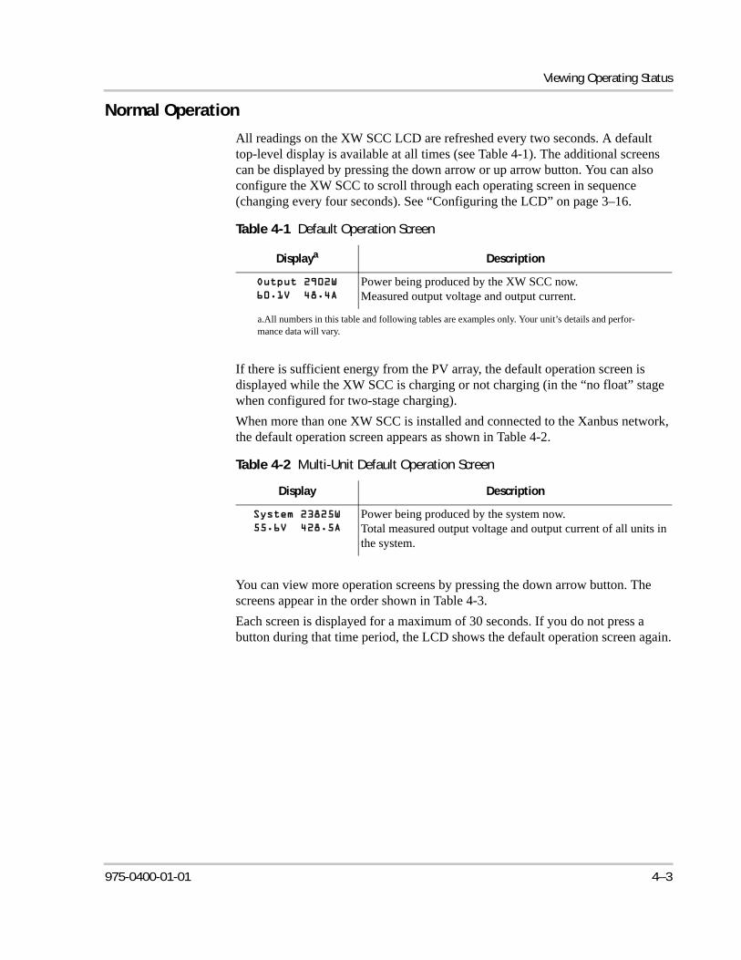
Viewing Operating Status
Normal Operation
All readings on the XW SCC LCD are refreshed every two seconds. A default top-level display is available at all times (see Table 4-1). The additional screens can be displayed by pressing the down arrow or up arrow button. You can also configure the XW SCC to scroll through each operating screen in sequence (changing every four seconds). See “Configuring the LCD” on page 3–16.
If there is sufficient energy from the PV array, the default operation screen is displayed while the XW SCC is charging or not charging (in the “no float” stage when configured for two-stage charging).
When more than one XW SCC is installed and connected to the Xanbus network, the default operation screen appears as shown in Table 4-2.
You can view more operation screens by pressing the down arrow button. The screens appear in the order shown in Table 4-3.
Each screen is displayed for a maximum of 30 seconds. If you do not press a button during that time period, the LCD shows the default operation screen again.
Table 4-1 Default Operation Screen
Displaya
a.All numbers in this table and following tables are examples only. Your unit’s details and perfor-mance data will vary.
Description
Power being produced by the XW SCC now.Measured output voltage and output current.
Table 4-2 Multi-Unit Default Operation Screen
Display Description
Power being produced by the system now.Total measured output voltage and output current of all units in the system.
975-0400-01-01 4–3
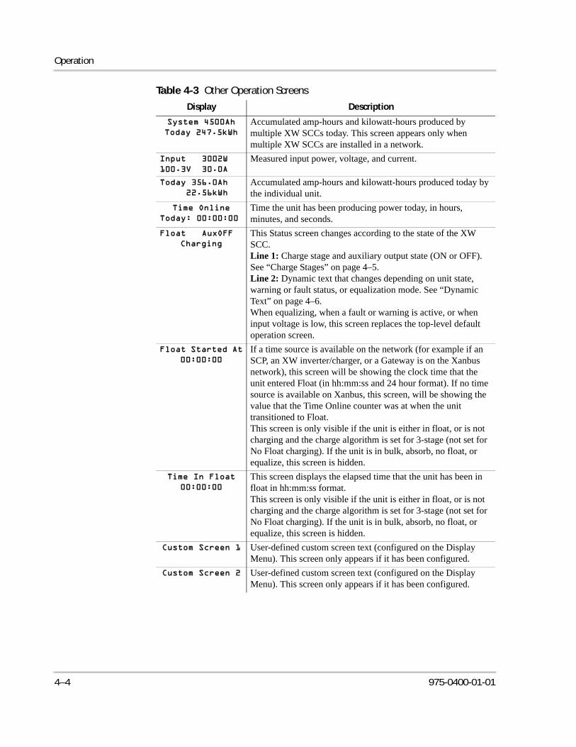
Operation
Table 4-3 Other Operation Screens
Display Description
Accumulated amp-hours and kilowatt-hours produced by multiple XW SCCs today. This screen appears only when multiple XW SCCs are installed in a network.
Measured input power, voltage, and current.
Accumulated amp-hours and kilowatt-hours produced today by the individual unit.
Time the unit has been producing power today, in hours, minutes, and seconds.
This Status screen changes according to the state of the XW SCC.Line 1: Charge stage and auxiliary output state (ON or OFF). See “Charge Stages” on page 4–5.Line 2: Dynamic text that changes depending on unit state, warning or fault status, or equalization mode. See “Dynamic Text” on page 4–6.When equalizing, when a fault or warning is active, or when input voltage is low, this screen replaces the top-level default operation screen.
If a time source is available on the network (for example if an SCP, an XW inverter/charger, or a Gateway is on the Xanbus network), this screen will be showing the clock time that the unit entered Float (in hh:mm:ss and 24 hour format). If no time source is available on Xanbus, this screen, will be showing the value that the Time Online counter was at when the unit transitioned to Float. This screen is only visible if the unit is either in float, or is not charging and the charge algorithm is set for 3-stage (not set for No Float charging). If the unit is in bulk, absorb, no float, or equalize, this screen is hidden.
This screen displays the elapsed time that the unit has been in float in hh:mm:ss format. This screen is only visible if the unit is either in float, or is not charging and the charge algorithm is set for 3-stage (not set for No Float charging). If the unit is in bulk, absorb, no float, or equalize, this screen is hidden.
User-defined custom screen text (configured on the Display Menu). This screen only appears if it has been configured.
User-defined custom screen text (configured on the Display Menu). This screen only appears if it has been configured.
4–4 975-0400-01-01
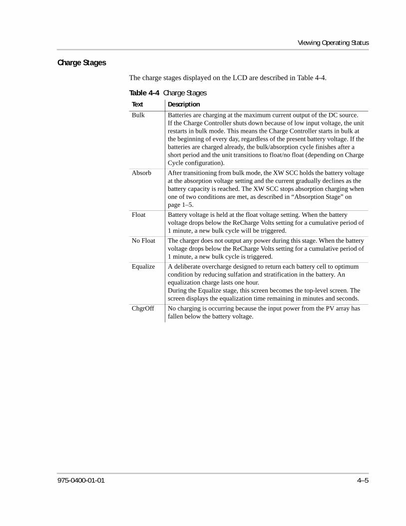
Viewing Operating Status
Charge Stages
The charge stages displayed on the LCD are described in Table 4-4.
Table 4-4 Charge Stages
Text Description
Bulk Batteries are charging at the maximum current output of the DC source.If the Charge Controller shuts down because of low input voltage, the unit restarts in bulk mode. This means the Charge Controller starts in bulk at the beginning of every day, regardless of the present battery voltage. If the batteries are charged already, the bulk/absorption cycle finishes after a short period and the unit transitions to float/no float (depending on Charge Cycle configuration).
Absorb After transitioning from bulk mode, the XW SCC holds the battery voltage at the absorption voltage setting and the current gradually declines as the battery capacity is reached. The XW SCC stops absorption charging when one of two conditions are met, as described in “Absorption Stage” on page 1–5.
Float Battery voltage is held at the float voltage setting. When the battery voltage drops below the ReCharge Volts setting for a cumulative period of 1 minute, a new bulk cycle will be triggered.
No Float The charger does not output any power during this stage. When the battery voltage drops below the ReCharge Volts setting for a cumulative period of 1 minute, a new bulk cycle is triggered.
Equalize A deliberate overcharge designed to return each battery cell to optimum condition by reducing sulfation and stratification in the battery. An equalization charge lasts one hour.During the Equalize stage, this screen becomes the top-level screen. The screen displays the equalization time remaining in minutes and seconds.
ChgrOff No charging is occurring because the input power from the PV array has fallen below the battery voltage.
975-0400-01-01 4–5
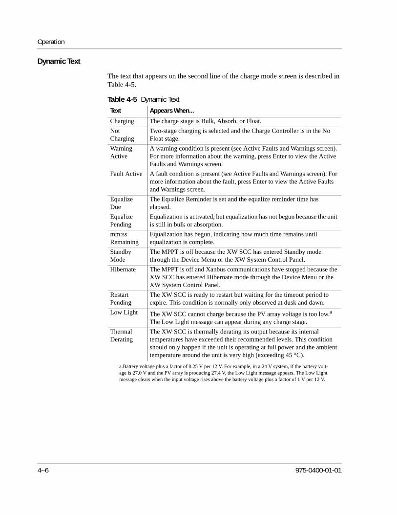
Operation
Dynamic Text
The text that appears on the second line of the charge mode screen is described in Table 4-5.
Table 4-5 Dynamic Text
Text Appears When...
Charging The charge stage is Bulk, Absorb, or Float.
Not Charging
Two-stage charging is selected and the Charge Controller is in the No Float stage.
Warning Active
A warning condition is present (see Active Faults and Warnings screen). For more information about the warning, press Enter to view the Active Faults and Warnings screen.
Fault Active A fault condition is present (see Active Faults and Warnings screen). For more information about the fault, press Enter to view the Active Faults and Warnings screen.
Equalize Due
The Equalize Reminder is set and the equalize reminder time has elapsed.
Equalize Pending
Equalization is activated, but equalization has not begun because the unit is still in bulk or absorption.
mm:ss Remaining
Equalization has begun, indicating how much time remains until equalization is complete.
Standby Mode
The MPPT is off because the XW SCC has entered Standby mode through the Device Menu or the XW System Control Panel.
Hibernate The MPPT is off and Xanbus communications have stopped because the XW SCC has entered Hibernate mode through the Device Menu or the XW System Control Panel.
Restart Pending
The XW SCC is ready to restart but waiting for the timeout period to expire. This condition is normally only observed at dusk and dawn.
Low Light The XW SCC cannot charge because the PV array voltage is too low.a The Low Light message can appear during any charge stage.
a.Battery voltage plus a factor of 0.25 V per 12 V. For example, in a 24 V system, if the battery volt-age is 27.0 V and the PV array is producing 27.4 V, the Low Light message appears. The Low Light message clears when the input voltage rises above the battery voltage plus a factor of 1 V per 12 V.
Thermal Derating
The XW SCC is thermally derating its output because its internal temperatures have exceeded their recommended levels. This condition should only happen if the unit is operating at full power and the ambient temperature around the unit is very high (exceeding 45 °C).
4–6 975-0400-01-01
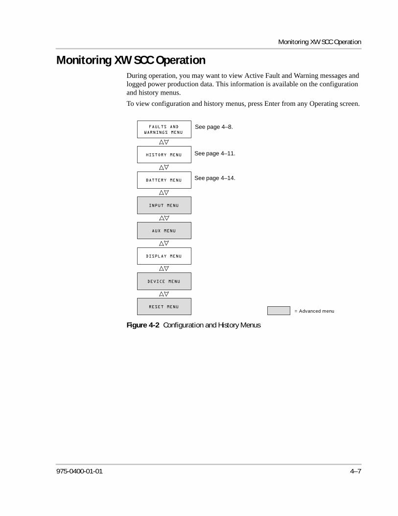
Monitoring XW SCC Operation
Monitoring XW SCC OperationDuring operation, you may want to view Active Fault and Warning messages and logged power production data. This information is available on the configuration and history menus.
To view configuration and history menus, press Enter from any Operating screen.
Figure 4-2 Configuration and History Menus
= Advanced menu
See page 4–8.
See page 4–11.
See page 4–14.
975-0400-01-01 4–7
Operation
Viewing Active Faults and Warnings
You can view active faults and warnings from the Faults and Warnings Menu.
Warning messages indicate a problem that could affect normal operation. “Warning Active” appears on the LCD to notify you of the warning condition. Normal operation continues until the warning condition:
• clears and normal operation continues
• escalates to a fault condition.
Fault messages indicate a fault condition. When a fault occurs, the XW SCC:
• displays “Fault Active” on the LCD
• disables the MPPT and charging functions
• opens the relay that connects its power circuits to the battery bank.
The only fault that does not disable normal XW SCC operation is the Auxiliary Output Overload Fault. The Auxiliary Output Overload Fault only disables the auxiliary output. Other XW SCC functions continue operating. The Ground Fault disables the auxiliary output as well as normal XW SCC operation.
Most warnings and faults clear automatically once the condition that caused them goes away. The only exceptions are the Auxiliary Output Overload Fault and the Ground Fault. The Auxiliary Output Overload Fault must be cleared manually. The Ground Fault requires you to correct the ground fault and restart the system. For more information, see Troubleshooting.
To view the complete list of active faults and warnings:
1. Press Enter on the Active Faults and Warning Menu screen.
2. Press the down button to view additional fault or warning messages.
If there are no active faults and warnings, no messages are displayed after you press Enter from the Active Faults and Warnings screen.
To manually clear a fault:
1. Identify the active fault from the Active Faults and Warning Menu.
The two faults you can manually clear are “Batt Under Volt” (except when the battery voltage has fallen below 10 V) and “Aux Output Ovld.” and See Table 4-6 for descriptions of these faults.
2. Press Exit to return to the Active Faults and Warnings Menu, then press the down arrow to view the Clear Fault screen.
“Batt Under Volt” is displayed first.
3. Press Enter to view the cursor.
4. Press Enter again to clear the “Batt Under Volt” fault.
Or
Note: The Faults and Warnings menu is visible only when the XW SCC has one or more active faults or warnings.
4–8 975-0400-01-01
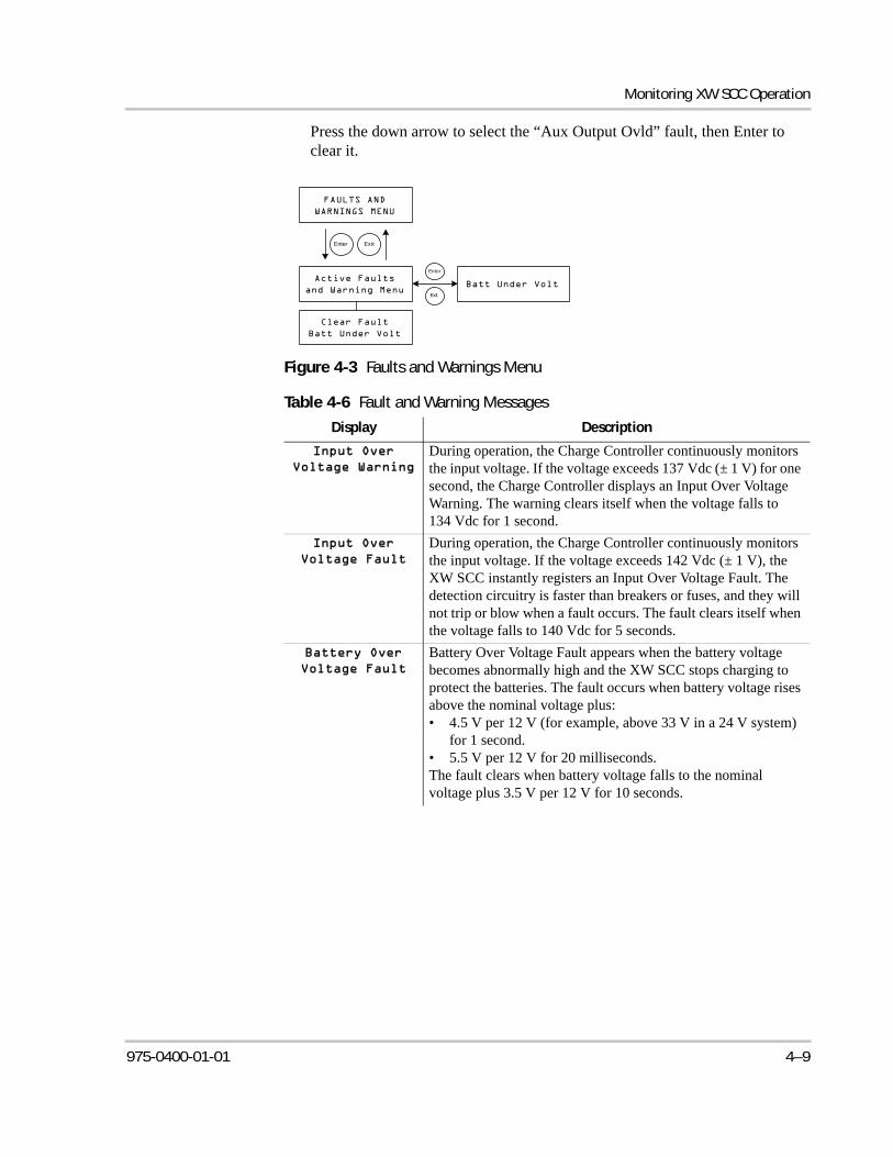
Monitoring XW SCC Operation
Press the down arrow to select the “Aux Output Ovld” fault, then Enter to clear it.
Figure 4-3 Faults and Warnings Menu
Table 4-6 Fault and Warning Messages
Display Description
During operation, the Charge Controller continuously monitors the input voltage. If the voltage exceeds 137 Vdc (± 1 V) for one second, the Charge Controller displays an Input Over Voltage Warning. The warning clears itself when the voltage falls to 134 Vdc for 1 second.
During operation, the Charge Controller continuously monitors the input voltage. If the voltage exceeds 142 Vdc (± 1 V), the XW SCC instantly registers an Input Over Voltage Fault. The detection circuitry is faster than breakers or fuses, and they will not trip or blow when a fault occurs. The fault clears itself when the voltage falls to 140 Vdc for 5 seconds.
Battery Over Voltage Fault appears when the battery voltage becomes abnormally high and the XW SCC stops charging to protect the batteries. The fault occurs when battery voltage rises above the nominal voltage plus: • 4.5 V per 12 V (for example, above 33 V in a 24 V system)
for 1 second.• 5.5 V per 12 V for 20 milliseconds.The fault clears when battery voltage falls to the nominal voltage plus 3.5 V per 12 V for 10 seconds.
Enter Exit
Exit
Enter
975-0400-01-01 4–9
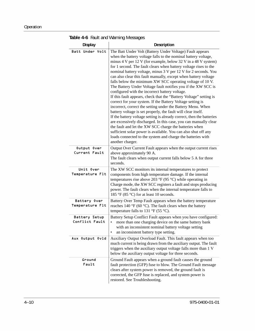
Operation
The Batt Under Volt (Battery Under Voltage) Fault appears when the battery voltage falls to the nominal battery voltage, minus 4 V per 12 V (for example, below 32 V in a 48 V system) for 1 second. The fault clears when battery voltage rises to the nominal battery voltage, minus 3 V per 12 V for 2 seconds. You can also clear this fault manually, except when battery voltage falls below the minimum XW SCC operating voltage of 10 V.The Battery Under Voltage fault notifies you if the XW SCC is configured with the incorrect battery voltage.If this fault appears, check that the “Battery Voltage” setting is correct for your system. If the Battery Voltage setting is incorrect, correct the setting under the Battery Menu. When battery voltage is set properly, the fault will clear itself.If the battery voltage setting is already correct, then the batteries are excessively discharged. In this case, you can manually clear the fault and let the XW SCC charge the batteries when sufficient solar power is available. You can also shut off any loads connected to the system and charge the batteries with another charger.
Output Over Current Fault appears when the output current rises above approximately 90 A.The fault clears when output current falls below 5 A for three seconds.
The XW SCC monitors its internal temperatures to protect components from high temperature damage. If the internal temperatures rise above 203 °F (95 °C) while operating in Charge mode, the XW SCC registers a fault and stops producing power. The fault clears when the internal temperature falls to 185 °F (85 °C) for at least 10 seconds.
Battery Over Temp Fault appears when the battery temperature reaches 140 °F (60 °C). The fault clears when the battery temperature falls to 131 °F (55 °C).
Battery Setup Conflict Fault appears when you have configured:• more than one charging device on the same battery bank
with an inconsistent nominal battery voltage setting• an inconsistent battery type setting.
Auxiliary Output Overload Fault. This fault appears when too much current is being drawn from the auxiliary output. The fault triggers when the auxiliary output voltage falls more than 1 V below the auxiliary output voltage for three seconds.
Ground Fault appears when a ground fault causes the ground fault protection (GFP) fuse to blow. The Ground Fault message clears after system power is removed, the ground fault is corrected, the GFP fuse is replaced, and system power is restored. See Troubleshooting.
Table 4-6 Fault and Warning Messages
Display Description
4–10 975-0400-01-01
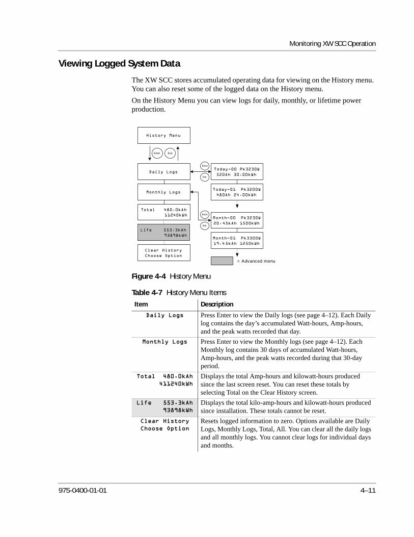
Monitoring XW SCC Operation
Viewing Logged System Data
The XW SCC stores accumulated operating data for viewing on the History menu. You can also reset some of the logged data on the History menu.
On the History Menu you can view logs for daily, monthly, or lifetime power production.
Figure 4-4 History Menu
Table 4-7 History Menu Items
Item Description
Press Enter to view the Daily logs (see page 4–12). Each Daily log contains the day’s accumulated Watt-hours, Amp-hours, and the peak watts recorded that day.
Press Enter to view the Monthly logs (see page 4–12). Each Monthly log contains 30 days of accumulated Watt-hours, Amp-hours, and the peak watts recorded during that 30-day period.
Displays the total Amp-hours and kilowatt-hours produced since the last screen reset. You can reset these totals by selecting Total on the Clear History screen.
Displays the total kilo-amp-hours and kilowatt-hours produced since installation. These totals cannot be reset.
Resets logged information to zero. Options available are Daily Logs, Monthly Logs, Total, All. You can clear all the daily logs and all monthly logs. You cannot clear logs for individual days and months.
Enter Exit
Exit
Enter
Exit
Enter
= Advanced menu
975-0400-01-01 4–11
Operation
Daily Logs
To view the daily logs stored in memory, press Enter from the Daily Logs screen, then press the down arrow button to view each log, starting with the most recent. On the log screen, the current day is “Today–00,” yesterday is “Today–01,” and so on. See Figure 4-4.
The XW SCC stores up to 30 daily logs. After 30 days, the oldest daily log is overwritten with the newest log.
After logging 30 daily logs, the XW SCC totals the collected data and creates a new monthly log.
Monthly Logs
To view the monthly logs stored in memory, press Enter from the Monthly Logs screen, then press the down arrow button to view each log, starting with the current month. On the log screen, the current month is “Month–00,” the previous month is “Month–01,” and so on. See Figure 4-4.
Monthly logs consist of the total data from the previous 30 daily logs. To the XW SCC, a “month” is a 30-day period, and does not match the months of the calendar.
The XW SCC stores up to 12 monthly logs. After 12 months the oldest monthly log is overwritten with the newest log.
4–12 975-0400-01-01
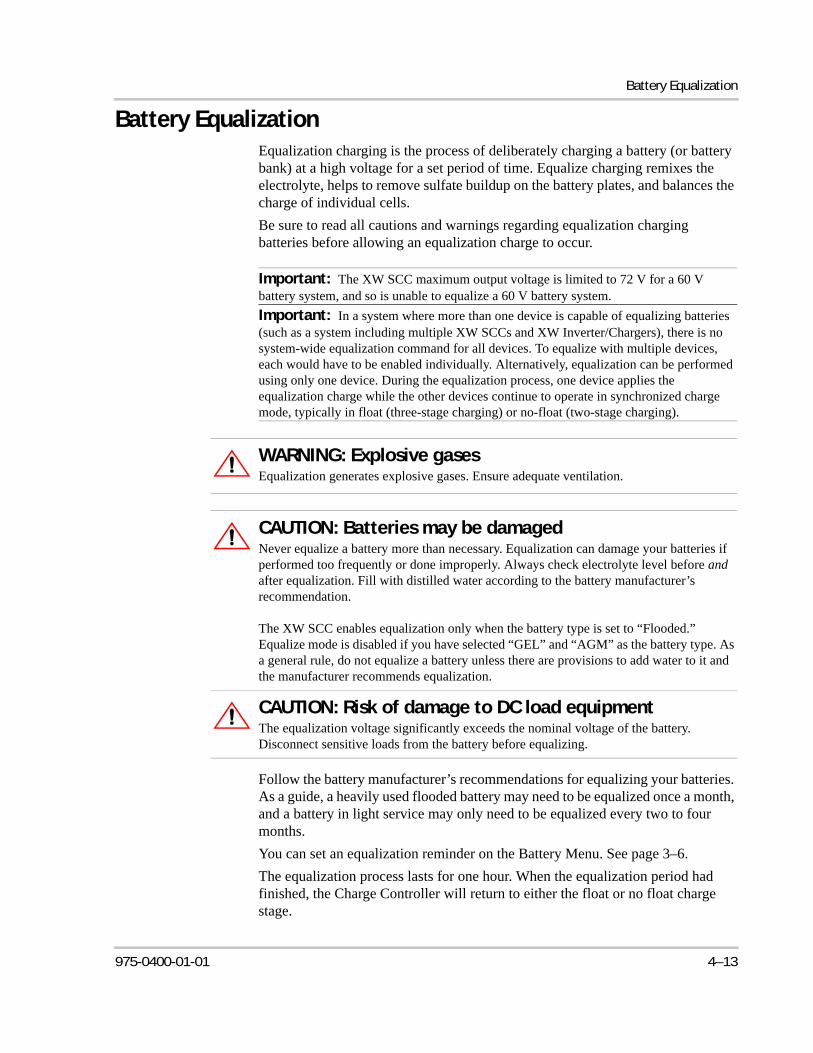
Battery Equalization
Battery EqualizationEqualization charging is the process of deliberately charging a battery (or battery bank) at a high voltage for a set period of time. Equalize charging remixes the electrolyte, helps to remove sulfate buildup on the battery plates, and balances the charge of individual cells.
Be sure to read all cautions and warnings regarding equalization charging batteries before allowing an equalization charge to occur.
Follow the battery manufacturer’s recommendations for equalizing your batteries. As a guide, a heavily used flooded battery may need to be equalized once a month, and a battery in light service may only need to be equalized every two to four months.
You can set an equalization reminder on the Battery Menu. See page 3–6.
The equalization process lasts for one hour. When the equalization period had finished, the Charge Controller will return to either the float or no float charge stage.
Important: The XW SCC maximum output voltage is limited to 72 V for a 60 V battery system, and so is unable to equalize a 60 V battery system.
Important: In a system where more than one device is capable of equalizing batteries (such as a system including multiple XW SCCs and XW Inverter/Chargers), there is no system-wide equalization command for all devices. To equalize with multiple devices, each would have to be enabled individually. Alternatively, equalization can be performed using only one device. During the equalization process, one device applies the equalization charge while the other devices continue to operate in synchronized charge mode, typically in float (three-stage charging) or no-float (two-stage charging).
WARNING: Explosive gasesEqualization generates explosive gases. Ensure adequate ventilation.
CAUTION: Batteries may be damagedNever equalize a battery more than necessary. Equalization can damage your batteries if performed too frequently or done improperly. Always check electrolyte level before and after equalization. Fill with distilled water according to the battery manufacturer’s recommendation.
The XW SCC enables equalization only when the battery type is set to “Flooded.” Equalize mode is disabled if you have selected “GEL” and “AGM” as the battery type. As a general rule, do not equalize a battery unless there are provisions to add water to it and the manufacturer recommends equalization.
CAUTION: Risk of damage to DC load equipmentThe equalization voltage significantly exceeds the nominal voltage of the battery. Disconnect sensitive loads from the battery before equalizing.
975-0400-01-01 4–13
Operation
To manually begin battery equalization:
1. From the Battery Menu screen, press Enter.
2. On the Equalize screen, select Activate.
If the battery is in the float or no float stage, the XW SCC goes back to the bulk stage and goes through a full charge cycle before entering the Equalization stage. The LCD displays “Equalization Pending” while the XW SCC performs this full charge cycle. The full charge cycle ensures that the batteries are fully charged before an equalization is attempted.
The Operating screen appears, indicating how much time, in minutes and seconds, remains in the equalization process.
The XW SCC applies the equalization charge for one hour. You can also stop the equalization process manually.
If conditions prevent the PV array from producing enough power for the XW SCC to provide an equalization charge, the equalization timer continues running. If conditions continue to make it difficult to complete a full equalization charge, use another device, such as an inverter/charger, to perform battery equalization.
To manually stop battery equalization:
1. From the Battery Menu screen, press Enter.
2. On the Equalize screen, select Stop.
Equalization stops, and the XW SCC goes to either the Float or No Float stage, depending on the charge mode selected.
4–14 975-0400-01-01
5 Troubleshooting
Chapter 5 contains information about identifying and resolving possible problems with systems using a XW Solar Charge Controller.
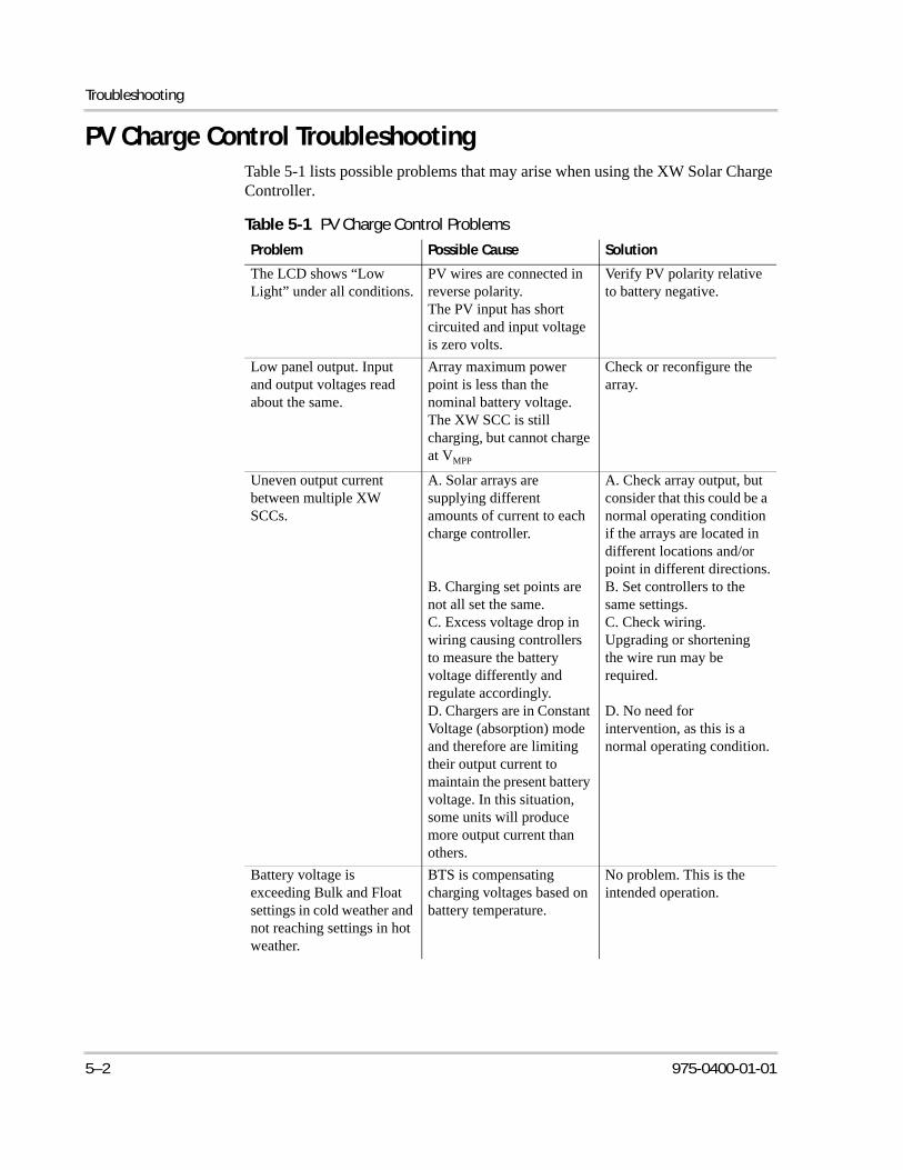
Troubleshooting
PV Charge Control TroubleshootingTable 5-1 lists possible problems that may arise when using the XW Solar Charge Controller.
Table 5-1 PV Charge Control Problems
Problem Possible Cause Solution
The LCD shows “Low Light” under all conditions.
PV wires are connected in reverse polarity.The PV input has short circuited and input voltage is zero volts.
Verify PV polarity relative to battery negative.
Low panel output. Input and output voltages read about the same.
Array maximum power point is less than the nominal battery voltage. The XW SCC is still charging, but cannot charge at VMPP
Check or reconfigure the array.
Uneven output current between multiple XW SCCs.
A. Solar arrays are supplying different amounts of current to each charge controller.
B. Charging set points are not all set the same.C. Excess voltage drop in wiring causing controllers to measure the battery voltage differently and regulate accordingly.D. Chargers are in Constant Voltage (absorption) mode and therefore are limiting their output current to maintain the present battery voltage. In this situation, some units will produce more output current than others.
A. Check array output, but consider that this could be a normal operating condition if the arrays are located in different locations and/or point in different directions.B. Set controllers to the same settings.C. Check wiring. Upgrading or shortening the wire run may be required.
D. No need for intervention, as this is a normal operating condition.
Battery voltage is exceeding Bulk and Float settings in cold weather and not reaching settings in hot weather.
BTS is compensating charging voltages based on battery temperature.
No problem. This is the intended operation.
5–2 975-0400-01-01
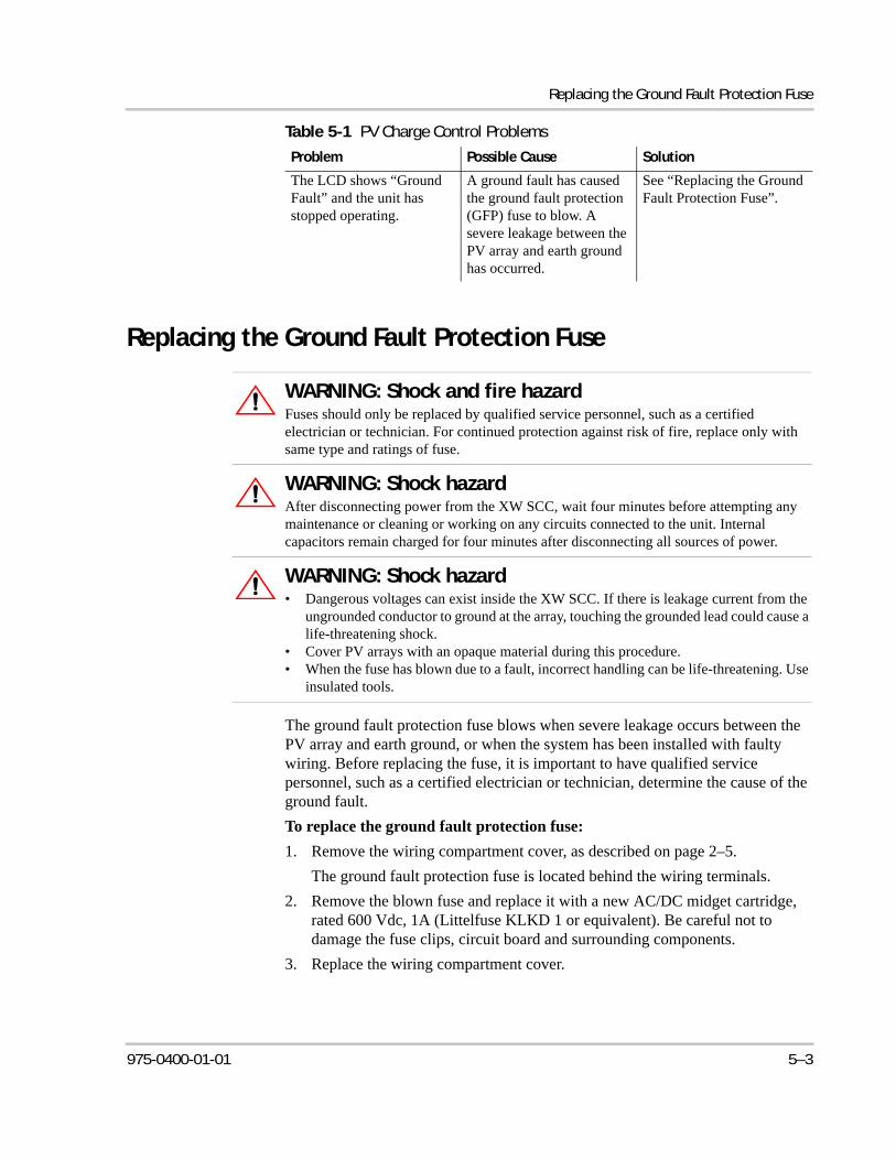
Replacing the Ground Fault Protection Fuse
Replacing the Ground Fault Protection Fuse
The ground fault protection fuse blows when severe leakage occurs between the PV array and earth ground, or when the system has been installed with faulty wiring. Before replacing the fuse, it is important to have qualified service personnel, such as a certified electrician or technician, determine the cause of the ground fault.
To replace the ground fault protection fuse:
1. Remove the wiring compartment cover, as described on page 2–5.
The ground fault protection fuse is located behind the wiring terminals.
2. Remove the blown fuse and replace it with a new AC/DC midget cartridge, rated 600 Vdc, 1A (Littelfuse KLKD 1 or equivalent). Be careful not to damage the fuse clips, circuit board and surrounding components.
3. Replace the wiring compartment cover.
The LCD shows “Ground Fault” and the unit has stopped operating.
A ground fault has caused the ground fault protection (GFP) fuse to blow. A severe leakage between the PV array and earth ground has occurred.
See “Replacing the Ground Fault Protection Fuse”.
WARNING: Shock and fire hazardFuses should only be replaced by qualified service personnel, such as a certified electrician or technician. For continued protection against risk of fire, replace only with same type and ratings of fuse.
WARNING: Shock hazardAfter disconnecting power from the XW SCC, wait four minutes before attempting any maintenance or cleaning or working on any circuits connected to the unit. Internal capacitors remain charged for four minutes after disconnecting all sources of power.
WARNING: Shock hazard• Dangerous voltages can exist inside the XW SCC. If there is leakage current from the
ungrounded conductor to ground at the array, touching the grounded lead could cause a life-threatening shock.
• Cover PV arrays with an opaque material during this procedure.• When the fuse has blown due to a fault, incorrect handling can be life-threatening. Use
insulated tools.
Table 5-1 PV Charge Control Problems
Problem Possible Cause Solution
975-0400-01-01 5–3

5–4
A Specifications
Appendix A provides the specifications for the XW Solar Charge Controller.
All specifications are subject to change without notice.
For information on: See:
“Electrical Specifications” page A–2
“Default Battery Charging Settings” page A–2
“Mechanical Specifications” page A–3
“Output Power Versus Ambient Temperature”
page A–3
“Optional Accessories” page A–4
“Regulatory Approvals” page A–4
Specifications
Electrical Specifications
Default Battery Charging SettingsAll settings in the following table are based on a 12-volt nominal battery bank. For the other nominal voltages, scale the values in this table appropriately (48-volt systems would use voltages four times that of the values listed in this table). An exception to this is for equalize voltage on a 60-volt system. The maximum programmable output voltage is 72 volts, but a 60-volt system would need to be equalized at 80 volts. Therefore, the maximum equalize voltage is limited to 72 volts on a 60-volt system.
Maximum PV Array Voltage (Operating) 140 Vdc
Maximum PV Array Open Circuit Voltage 150 Vdc
Array Short Circuit Current 60 Adc maximum
Nominal Battery Voltage 12, 24, 36, 48, 60 Vdc
Battery Voltage Range (Operating) 10 Vdc to 80 Vdc
Maximum Output Current 60 A (for all battery voltages except 60 V)
Maximum Output Power 3500 W
Auxiliary Output 5–13 V, up to 200 mA
Tare Loss/Night-time Power Consumption 2.5 W
Charger Regulation Method Three-stage (bulk, absorption, float)Two-stage (bulk, absorption)
Setting
Battery Type
Floodeda
a.When a Custom battery type is selected, the default set-tings are based on the Flooded battery type.
Gel AGM
Equalize Voltage 16.0V n/a n/a
ReCharge Voltage 12.5 V 12.5 V 12.5 V
Bulk Voltage 14.4 V 14.2 V 14.3 V
Absorption Voltage 14.4 V 14.2 V 14.3 V
Float Voltage 13.5 V 13.8 V 13.4 V
Absorption Time 180 min 180 min 180 min
Batt Temp Comp -27mV/C -27mV/C -21mV/C
A–2 975-0400-01-01
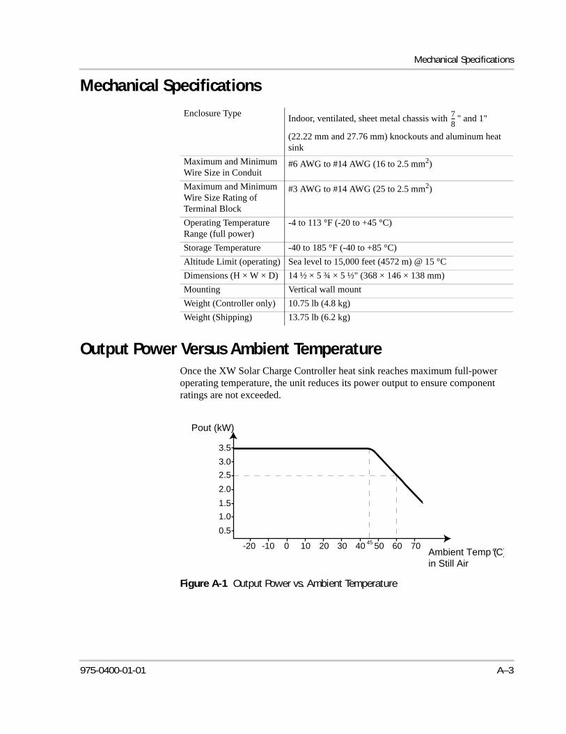
Mechanical Specifications
Mechanical Specifications
Output Power Versus Ambient TemperatureOnce the XW Solar Charge Controller heat sink reaches maximum full-power operating temperature, the unit reduces its power output to ensure component ratings are not exceeded.
Enclosure TypeIndoor, ventilated, sheet metal chassis with " and 1"
(22.22 mm and 27.76 mm) knockouts and aluminum heat sink
Maximum and Minimum Wire Size in Conduit
#6 AWG to #14 AWG (16 to 2.5 mm2)
Maximum and Minimum Wire Size Rating of Terminal Block
#3 AWG to #14 AWG (25 to 2.5 mm2)
Operating Temperature Range (full power)
-4 to 113 °F (-20 to +45 °C)
Storage Temperature -40 to 185 °F (-40 to +85 °C)
Altitude Limit (operating) Sea level to 15,000 feet (4572 m) @ 15 °C
Dimensions (H × W × D) 14 ½ × 5 ¾ × 5 ½" (368 × 146 × 138 mm)
Mounting Vertical wall mount
Weight (Controller only) 10.75 lb (4.8 kg)
Weight (Shipping) 13.75 lb (6.2 kg)
78---
Figure A-1 Output Power vs. Ambient Temperature
Pout (kW)
Ambient Temp (°C)in Still Air
-20 -10 0 10 20 30 40 50 60 70
0.5
1.0
1.5
2.0
2.5
3.0
3.5
45
975-0400-01-01 A–3
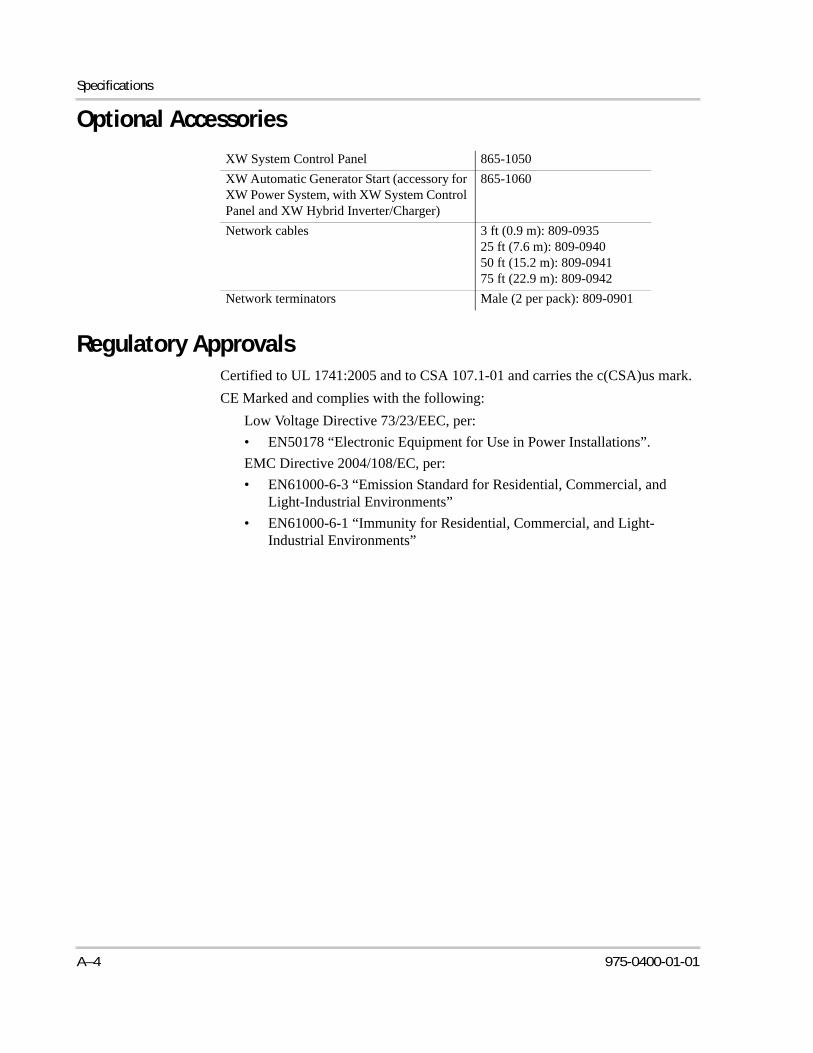
Specifications
Optional Accessories
Regulatory ApprovalsCertified to UL 1741:2005 and to CSA 107.1-01 and carries the c(CSA)us mark.
CE Marked and complies with the following:
Low Voltage Directive 73/23/EEC, per:
• EN50178 “Electronic Equipment for Use in Power Installations”.
EMC Directive 2004/108/EC, per:
• EN61000-6-3 “Emission Standard for Residential, Commercial, and Light-Industrial Environments”
• EN61000-6-1 “Immunity for Residential, Commercial, and Light-Industrial Environments”
XW System Control Panel 865-1050
XW Automatic Generator Start (accessory for XW Power System, with XW System Control Panel and XW Hybrid Inverter/Charger)
865-1060
Network cables 3 ft (0.9 m): 809-093525 ft (7.6 m): 809-094050 ft (15.2 m): 809-094175 ft (22.9 m): 809-0942
Network terminators Male (2 per pack): 809-0901
A–4 975-0400-01-01
B XW System Control Panel Menus
Appendix B is a guide to the XW Solar Charge Controller monitoring and configuration menus on the XW System Control Panel. The System Control Panel may be installed if the XW SCC is part of a power management system that includes an inverter/charger.
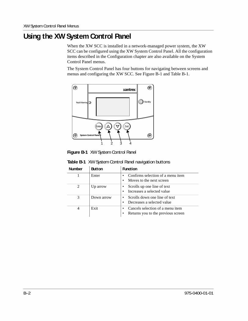
XW System Control Panel Menus
Using the XW System Control PanelWhen the XW SCC is installed in a network-managed power system, the XW SCC can be configured using the XW System Control Panel. All the configuration items described in the Configuration chapter are also available on the System Control Panel menus.
The System Control Panel has four buttons for navigating between screens and menus and configuring the XW SCC. See Figure B-1 and Table B-1.
Figure B-1 XW System Control Panel
Table B-1 XW System Control Panel navigation buttons
Number Button Function
1 Enter • Confirms selection of a menu item • Moves to the next screen
2 Up arrow • Scrolls up one line of text• Increases a selected value
3 Down arrow • Scrolls down one line of text• Decreases a selected value
4 Exit • Cancels selection of a menu item• Returns you to the previous screen
Fault/Warning
System Control Panel II
Standby
1 2 3 4
B–2 975-0400-01-01
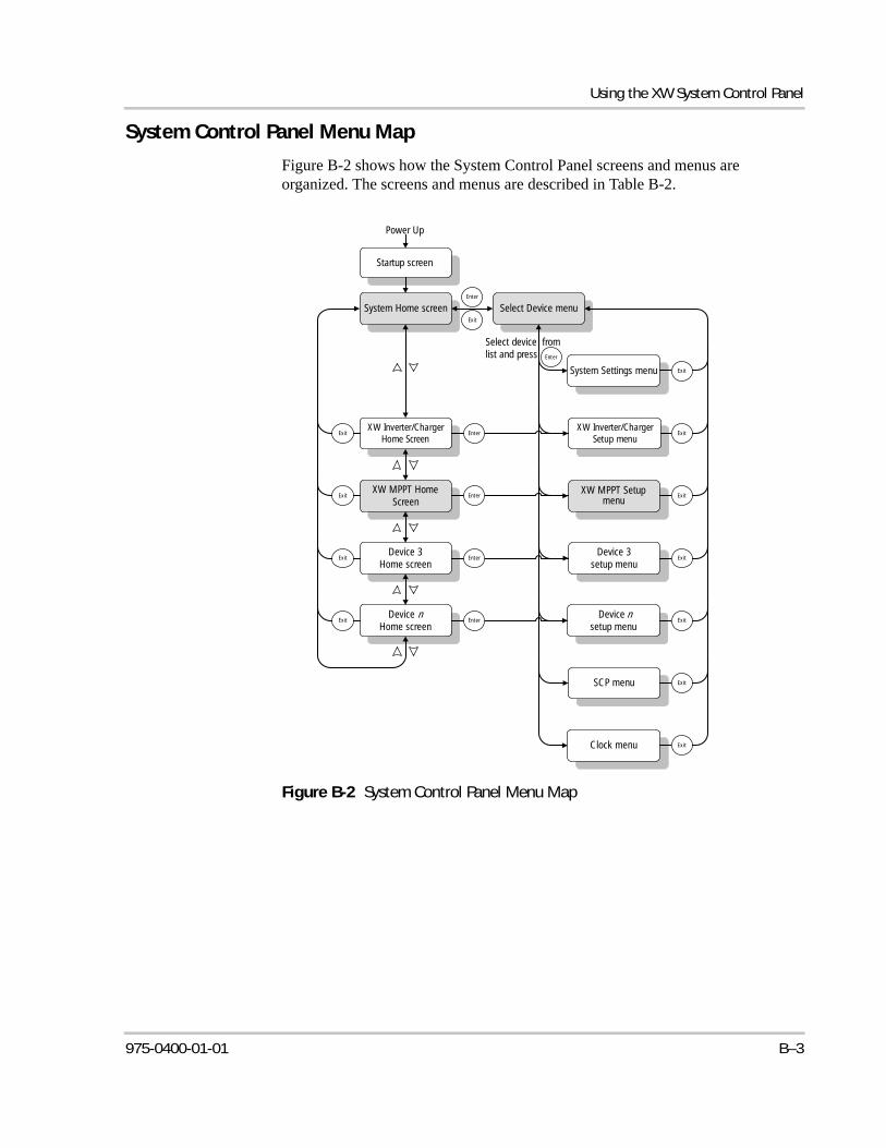
Using the XW System Control Panel
System Control Panel Menu Map
Figure B-2 shows how the System Control Panel screens and menus are organized. The screens and menus are described in Table B-2.
Figure B-2 System Control Panel Menu Map
Startup screen
Power Up
System Home screen
XW Inverter/Charger Home Screen
System Settings menu
SCP menu
XW MPPT Setup menu
Clock menu
XW Inverter/Charger Setup menu
Enter
Exit
XW MPPT Home Screen
Device 3 Home screen
Device nHome screen
Exit
Select Device menu
Device 3 setup menu
Device nsetup menu
Enter
Enter
Enter
Enter
Enter
Exit
Exit
Exit
Exit
Exit
Exit
Exit
Exit
Exit
Exit
Select device from list and press
975-0400-01-01 B–3
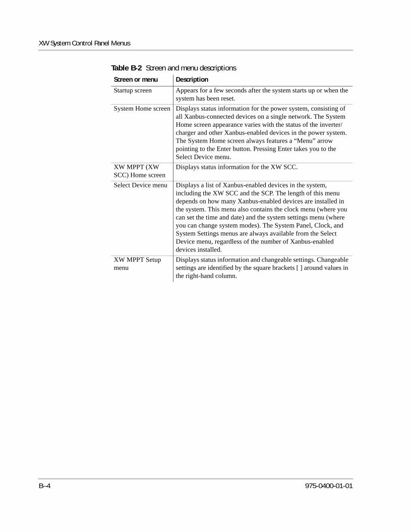
XW System Control Panel Menus
Table B-2 Screen and menu descriptions
Screen or menu Description
Startup screen Appears for a few seconds after the system starts up or when the system has been reset.
System Home screen Displays status information for the power system, consisting of all Xanbus-connected devices on a single network. The System Home screen appearance varies with the status of the inverter/charger and other Xanbus-enabled devices in the power system. The System Home screen always features a “Menu” arrow pointing to the Enter button. Pressing Enter takes you to the Select Device menu.
XW MPPT (XW SCC) Home screen
Displays status information for the XW SCC.
Select Device menu Displays a list of Xanbus-enabled devices in the system, including the XW SCC and the SCP. The length of this menu depends on how many Xanbus-enabled devices are installed in the system. This menu also contains the clock menu (where you can set the time and date) and the system settings menu (where you can change system modes). The System Panel, Clock, and System Settings menus are always available from the Select Device menu, regardless of the number of Xanbus-enabled devices installed.
XW MPPT Setup menu
Displays status information and changeable settings. Changeable settings are identified by the square brackets [ ] around values in the right-hand column.
B–4 975-0400-01-01
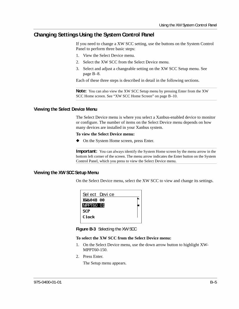
Using the XW System Control Panel
Changing Settings Using the System Control Panel
If you need to change a XW SCC setting, use the buttons on the System Control Panel to perform three basic steps:
1. View the Select Device menu.
2. Select the XW SCC from the Select Device menu.
3. Select and adjust a changeable setting on the XW SCC Setup menu. See page B–8.
Each of these three steps is described in detail in the following sections.
Viewing the Select Device Menu
The Select Device menu is where you select a Xanbus-enabled device to monitor or configure. The number of items on the Select Device menu depends on how many devices are installed in your Xanbus system.
To view the Select Device menu:
◆ On the System Home screen, press Enter.
Viewing the XW SCC Setup Menu
On the Select Device menu, select the XW SCC to view and change its settings.
To select the XW SCC from the Select Device menu:
1. On the Select Device menu, use the down arrow button to highlight XW-MPPT60-150.
2. Press Enter.
The Setup menu appears.
Note: You can also view the XW SCC Setup menu by pressing Enter from the XW SCC Home screen. See “XW SCC Home Screen” on page B–10.
Important: You can always identify the System Home screen by the menu arrow in the bottom left corner of the screen. The menu arrow indicates the Enter button on the System Control Panel, which you press to view the Select Device menu.
Figure B-3 Selecting the XW SCC
Select Device
MPPT60 01
975-0400-01-01 B–5
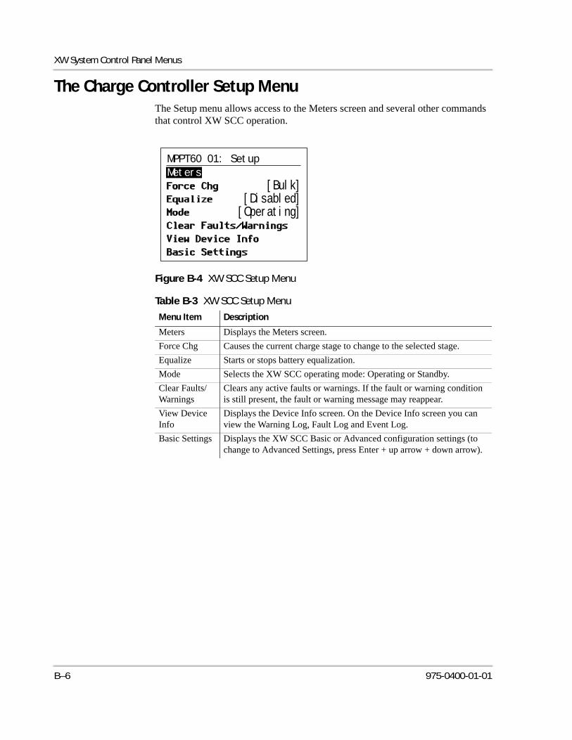
XW System Control Panel Menus
The Charge Controller Setup MenuThe Setup menu allows access to the Meters screen and several other commands that control XW SCC operation.
Figure B-4 XW SCC Setup Menu
Table B-3 XW SCC Setup Menu
Menu Item Description
Meters Displays the Meters screen.
Force Chg Causes the current charge stage to change to the selected stage.
Equalize Starts or stops battery equalization.
Mode Selects the XW SCC operating mode: Operating or Standby.
Clear Faults/Warnings
Clears any active faults or warnings. If the fault or warning condition is still present, the fault or warning message may reappear.
View Device Info
Displays the Device Info screen. On the Device Info screen you can view the Warning Log, Fault Log and Event Log.
Basic Settings Displays the XW SCC Basic or Advanced configuration settings (to change to Advanced Settings, press Enter + up arrow + down arrow).
MPPT60 01: Setup
Meters
[Bulk][Disabled]
[Operating]
B–6 975-0400-01-01
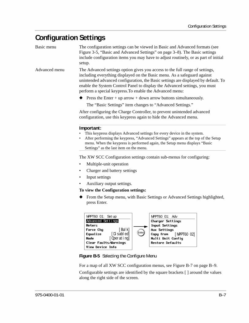
Configuration Settings
Configuration SettingsBasic menu The configuration settings can be viewed in Basic and Advanced formats (see
Figure 3-5, “Basic and Advanced Settings” on page 3–8). The Basic settings include configuration items you may have to adjust routinely, or as part of initial setup.
Advanced menu The Advanced settings option gives you access to the full range of settings, including everything displayed on the Basic menu. As a safeguard against unintended advanced configuration, the Basic settings are displayed by default. To enable the System Control Panel to display the Advanced settings, you must perform a special keypress.To enable the Advanced menu:
◆ Press the Enter + up arrow + down arrow buttons simultaneously.
The “Basic Settings” item changes to “Advanced Settings.”
After configuring the Charge Controller, to prevent unintended advanced configuration, use this keypress again to hide the Advanced menu.
The XW SCC Configuration settings contain sub-menus for configuring:
• Multiple-unit operation
• Charger and battery settings
• Input settings
• Auxiliary output settings.
To view the Configuration settings:
◆ From the Setup menu, with Basic Settings or Advanced Settings highlighted, press Enter.
For a map of all XW SCC configuration menus, see Figure B-7 on page B–9.
Configurable settings are identified by the square brackets [ ] around the values along the right side of the screen.
Important:• This keypress displays Advanced settings for every device in the system.• After performing the keypress, “Advanced Settings” appears at the top of the Setup
menu. When the keypress is performed again, the Setup menu displays “Basic Settings” as the last item on the menu.
Figure B-5 Selecting the Configure Menu
MPPT60 01: Adv
[MPPT60 02]
MPPT60 01: Setup
Advanced Settings
[Bulk][Disabled][Operating]
975-0400-01-01 B–7
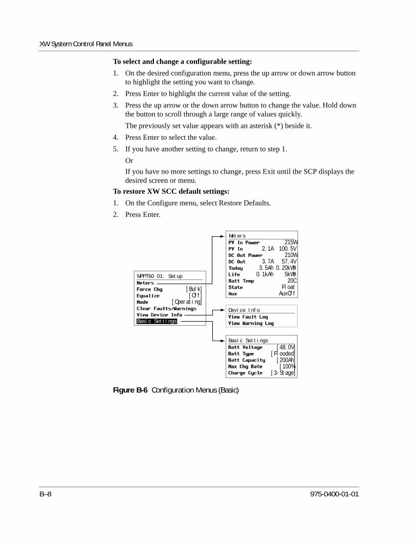
XW System Control Panel Menus
To select and change a configurable setting:
1. On the desired configuration menu, press the up arrow or down arrow button to highlight the setting you want to change.
2. Press Enter to highlight the current value of the setting.
3. Press the up arrow or the down arrow button to change the value. Hold down the button to scroll through a large range of values quickly.
The previously set value appears with an asterisk (*) beside it.
4. Press Enter to select the value.
5. If you have another setting to change, return to step 1.
Or
If you have no more settings to change, press Exit until the SCP displays the desired screen or menu.
To restore XW SCC default settings:
1. On the Configure menu, select Restore Defaults.
2. Press Enter.
Figure B-6 Configuration Menus (Basic)
Basic Settings
Device Info
[48.0V][Flooded]
[200Ah][100%]
[3-Stage]
MPPT60 01: Setup
Basic Settings
[Bulk][Off]
[Operating]
Meters
215W2.1A 100.5V
210W3.7A 57.4V3.5Ah 0.20kWh0.1kAh 5kWh
20CFloatAuxOff
B–8 975-0400-01-01
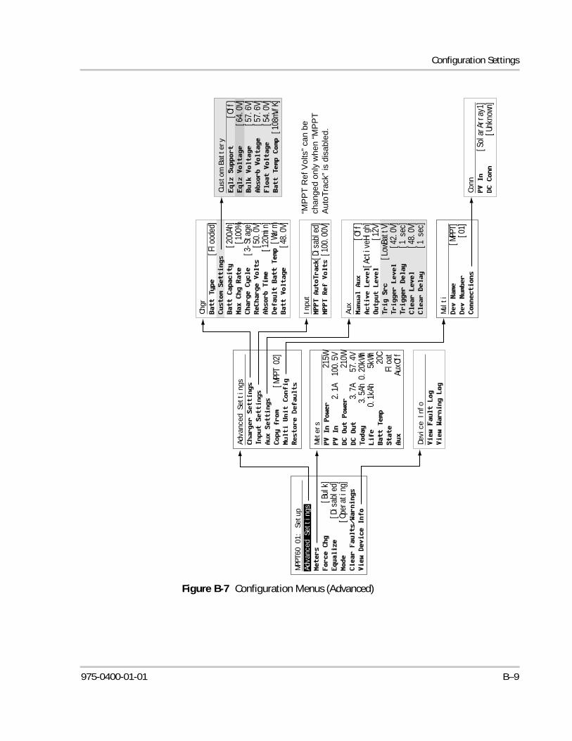
Configuration Settings
Figure B-7 Configuration Menus (Advanced)
Advanced Settings
Device Info
[MPPT 02]
Multi
[MPPT]
[01]
Chgr
[Flooded]
[200Ah]
[100%]
[3-Stage]
[50.0V]
[120min]
[Warm]
[48.0V]
Input
[Disabled]
[100.00V]
Aux
[Off]
[ActiveHigh]
[12V]
[LowBattV]
[42.0V]
[1 sec]
[48.0V]
[1 sec]
Conn
[SolarArray1]
[Unknown]
Custom Battery
[Off]
[64.0V]
[57.6V]
[57.6V]
[54.0V]
[108mV/K]
MPPT60 01: Setup
Advanced Settings
[Bulk]
[Disabled]
[Operating]
Meters
215W
2.1A 100.5V
210W
3.7A 57.4V
3.5Ah 0.20kWh
0.1kAh 5kWh
20C
Float
AuxOff
“MP
PT
Ref
Vol
ts”
can
be
chan
ged
only
wh
en “
MP
PT
A
uto
Tra
ck”
is d
isab
led.
975-0400-01-01 B–9
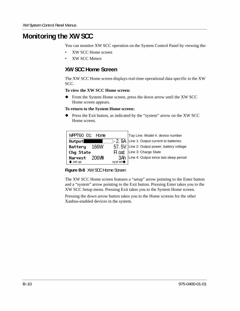
XW System Control Panel Menus
Monitoring the XW SCCYou can monitor XW SCC operation on the System Control Panel by viewing the:
• XW SCC Home screen
• XW SCC Meters
XW SCC Home Screen
The XW SCC Home screen displays real-time operational data specific to the XW SCC.
To view the XW SCC Home screen:
◆ From the System Home screen, press the down arrow until the XW SCC Home screen appears.
To return to the System Home screen:
◆ Press the Exit button, as indicated by the “system” arrow on the XW SCC Home screen.
The XW SCC Home screen features a “setup” arrow pointing to the Enter button and a “system” arrow pointing to the Exit button. Pressing Enter takes you to the XW SCC Setup menu. Pressing Exit takes you to the System Home screen.
Pressing the down arrow button takes you to the Home screens for the other Xanbus-enabled devices in the system.
Figure B-8 XW SCC Home Screen
setup system
MPPT60 01: Home
-2.9A166W 57.5V
Float206Wh 3Ah
Top Line: Model #, device number
Line 1: Output current to batteries
Line 2: Output power, battery voltage
Line 3: Charge State
Line 4: Output since last sleep period
B–10 975-0400-01-01
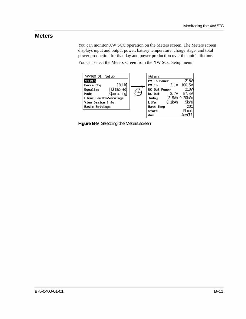
Monitoring the XW SCC
Meters
You can monitor XW SCC operation on the Meters screen. The Meters screen displays input and output power, battery temperature, charge stage, and total power production for that day and power production over the unit’s lifetime.
You can select the Meters screen from the XW SCC Setup menu.
Figure B-9 Selecting the Meters screen
Meters
[Bulk][Disabled][Operating]
Meters
215W2.1A 100.5V
210W3.7A 57.4V
3.5Ah 0.20kWh0.1kAh 5kWh
20CFloatAuxOff
MPPT60 01: Setup
975-0400-01-01 B–11

B–12

C Boost Charging
Appendix C provides information on Boost Charging for flooded lead-acid batteries in off-grid applications.

Boost Charging
Using Boost ChargingBoost charging allows for better utilization of flooded lead acid batteries under moderate cycling in off grid applications. Boost charging encourages a short duration charging voltage - above the gassing voltage - at the beginning of the absorption charge state. Testing has shown that boost charging improves battery performance by providing a regular mixing of the liquid electrolyte. Boost charging specifically discourages capacity-robbing acid stratification and plate sulfation.
Boost mode charging can be enabled by selecting 'custom' battery type and by setting the bulk voltage higher than the absorption voltage. The multi-stage charge algorithm then attempts to use the higher bulk voltage for the first hour of the absorption stage - unless interrupted by the max absorption timer or exit current threshold.
1. Boost charging encourages gassing of flooded Lead acid batteries.
2. Boost charging is NOT recommended for AGM, GEL or any other electrolyte-limited and/or valve regulated sealed battery application.
3. Boost charging may result in higher-than-normal water consumption. However, the benefits of boost charging are likely to be greater than the extra watering effort. Check battery water levels at least once per month.
4. Boost charging has maximum benefit when used on batteries that experience moderate cycling. An unoccupied cottage, for example, where batteries are full the majority of the time, may not benefit from boost charging - especially if battery watering is difficult.
WARNING: Explosive gasesAlways ensure adequate battery ventilation.
C–2 975-0400-01-01
Warranty and Return Information
WarrantyWhat does this warranty cover and how long does it last? This Limited Warranty is provided by Xantrex Technology Inc. ("Xantrex") and covers defects in workmanship and materials in your XW Solar Charge Controller. This warranty period lasts for 5 years from the date of purchase at the point of sale to you, the original end user customer, unless otherwise agreed in writing (the “Warranty Period”). You will be required to demonstrate proof of purchase to make warranty claims.This Limited Warranty is transferable to subsequent owners but only for the unexpired portion of the Warranty Period. Subsequent owners also require original proof of purchase as described in "What proof of purchase is required?"
What will Xantrex do? During the Warranty Period Xantrex will, at its option, repair the product (if economically feasible) or replace the defective product free of charge, provided that you notify Xantrex of the product defect within the Warranty Period, and provided that Xantrex through inspection establishes the existence of such a defect and that it is covered by this Limited Warranty. Xantrex will, at its option, use new and/or reconditioned parts in performing warranty repair and building replacement products. Xantrex reserves the right to use parts or products of original or improved design in the repair or replacement. If Xantrex repairs or replaces a product, its warranty continues for the remaining portion of the original Warranty Period or 90 days from the date of the return shipment to the customer, whichever is greater. All replaced products and all parts removed from repaired products become the property of Xantrex.Xantrex covers both parts and labor necessary to repair the product, and return shipment to the customer via a Xantrex-selected non-expedited surface freight within the contiguous United States and Canada. Alaska,Hawaii and outside of the United States and Canada are excluded. Contact Xantrex Customer Service for details on freight policy for return shipments from excluded areas.
How do you get service? If your product requires troubleshooting or warranty service, contact your merchant. If you are unable to contact your merchant, or the merchant is unable to provide service, contact Xantrex directly at:
Direct returns may be performed according to the Xantrex Return Material Authorization Policy described in your product manual. For some products, Xantrex maintains a network of regional Authorized Service Centers. Call Xantrex or check our website to see if your product can be repaired at one of these facilities.
What proof of purchase is required? In any warranty claim, dated proof of purchase must accompany the product and the product must not have been disassembled or modified without prior written authorization by Xantrex. Proof of purchase may be in any one of the following forms:
• The dated purchase receipt from the original purchase of the product at point of sale to the end user; or• The dated dealer invoice or purchase receipt showing original equipment manufacturer (OEM) status; or• The dated invoice or purchase receipt showing the product exchanged under warranty.
What does this warranty not cover? Claims are limited to repair and replacement, or if in Xantrex's discretion that is not possible, reimbursement up to the purchase price paid for the product. Xantrex will be liable to you only for direct damages suffered by you and only up to a maximum amount equal to the purchase price of the product.This Limited Warranty does not warrant uninterrupted or error-free operation of the product or cover normal wear and tear of the product or costs related to the removal, installation, or troubleshooting of the customer's electrical systems. This warranty does not apply to and Xantrex will not be responsible for any defect in or damage to:a) the product if it has been misused, neglected, improperly installed, physically damaged or altered, either
Telephone: +34 902.10.18.13 1 866 519 1470 (Toll free North America only)1 650 351 8237 (N.A.)
Fax: +34 93.305.50.26 1 604 422 2756 (N.A.)
Email: [email protected] [email protected]
Website: www.xantrex.com www.xantrex.com
975-0400-01-01 WA–1
Warranty and Return
internally or externally, or damaged from improper use or use in an unsuitable environment;b) the product if it has been subjected to fire, water, generalized corrosion, biological infestations, or input voltage
that creates operating conditions beyond the maximum or minimum limits listed in the Xantrex product specifications including, but not limited to, high input voltage from generators and lightning strikes;
c) the product if repairs have been done to it other than by Xantrex or its authorized service centers (hereafter "ASCs");
d) the product if it is used as a component part of a product expressly warranted by another manufacturer;e) component parts or monitoring systems supplied by you or purchased by Xantrex at your direction for
incorporation into the product;f) the product if its original identification (trade-mark, serial number) markings have been defaced, altered, or
removed;g) the product if it is located outside of the country where it was purchased; andh) any consequential losses that are attributable to the product losing power whether by product malfunction,
installation error or misuse.
Disclaimer
ProductTHIS LIMITED WARRANTY IS THE SOLE AND EXCLUSIVE WARRANTY PROVIDED BY XANTREX IN CONNECTION WITH YOUR XANTREX PRODUCT AND IS, WHERE PERMITTED BY LAW, IN LIEU OF ALL OTHER WARRANTIES, CONDITIONS, GUARANTEES, REPRESENTATIONS, OBLIGATIONS AND LIABILITIES, EXPRESS OR IMPLIED, STATUTORY OR OTHERWISE IN CONNECTION WITH THE PRODUCT, HOWEVER ARISING (WHETHER BY CONTRACT, TORT, NEGLIGENCE, PRINCIPLES OF MANUFACTURER'S LIABILITY, OPERATION OF LAW, CONDUCT, STATEMENT OR OTHERWISE), INCLUDING WITHOUT RESTRICTION ANY IMPLIED WARRANTY OR CONDITION OF QUALITY, MERCHANTABILITY OR FITNESS FOR A PARTICULAR PURPOSE. ANY IMPLIED WARRANTY OF MERCHANTABILITY OR FITNESS FOR A PARTICULAR PURPOSE TO THE EXTENT REQUIRED UNDER APPLICABLE LAW TO APPLY TO THE PRODUCT SHALL BE LIMITED IN DURATION TO THE PERIOD STIPULATED UNDER THIS LIMITED WARRANTY.
IN NO EVENT WILL XANTREX BE LIABLE FOR: (A) ANY SPECIAL, INDIRECT, INCIDENTAL OR CONSEQUENTIAL DAMAGES, INCLUDING LOST PROFITS, LOST REVENUES, FAILURE TO REALIZE EXPECTED SAVINGS, OR OTHER COMMERCIAL OR ECONOMIC LOSSES OF ANY KIND, EVEN IF XANTREX HAS BEEN ADVISED, OR HAD REASON TO KNOW, OF THE POSSIBILITY OF SUCH DAMAGE; (B) ANY LIABILITY ARISING IN TORT, WHETHER OR NOT ARISING OUT OF XANTREX'S NEGLIGENCE, AND ALL LOSSES OR DAMAGES TO ANY PROPERTY OR FOR ANY PERSONAL INJURY OR ECONOMIC LOSS OR DAMAGE CAUSED BY THE CONNECTION OF A PRODUCT TO ANY OTHER DEVICE OR SYSTEM; AND (C) ANY DAMAGE OR INJURY ARISING FROM OR AS A RESULT OF MISUSE OR ABUSE, OR THE INCORRECT INSTALLATION, INTEGRATION OR OPERATION OF THE PRODUCT BY PERSONS NOT AUTHORIZED BY XANTREX.
CONSUMERS IN THE EUROPEAN UNION:IF YOU ARE A CONSUMER (RATHER THAN A PURCHASER OF THE PRODUCT IN THE COURSE OF A BUSINESS) AND PURCHASED THE PRODUCT IN A MEMBER STATE OF THE EUROPEAN UNION, THIS LIMITED WARRANTY SHALL BE SUBJECT TO YOUR STATUTORY RIGHTS AS A CONSUMER UNDER THE EUROPEAN UNION PRODUCT WARRANTY DIRECTIVE 1999/44/EC AND AS SUCH DIRECTIVE HAS BEEN IMPLEMENTED IN THE EUROPEAN UNION MEMBER STATE WHERE YOU PURCHASED THE PRODUCT. FURTHER, WHILE THIS LIMITED WARRANTY GIVES YOU SPECIFIC LEGAL RIGHTS, YOU MAY HAVE OTHER RIGHTS WHICH MAY VARY FROM EU MEMBER STATE TO EU MEMBER STATE OR, IF YOU DID NOT PURCHASE THE PRODUCT IN AN EU MEMBER STATE, IN THE COUNTRY YOU PURCHASED THE PRODUCT WHICH MAY VARY FROM COUNTRY TO COUNTRY AND JURISDICTION TO JURISDICTION.
CONSUMERS IN THE REST OF THE WORLD:Exclusions
If this product is a consumer product, federal law does not allow an exclusion of implied warranties. To the extent you are entitled to implied warranties under federal law, to the extent permitted by applicable law they are limited to the duration of this Limited Warranty. Some states, provinces and jurisdictions do not allow limitations or exclusions on implied warranties or on the duration of an implied warranty or on the limitation or exclusion of incidental or consequential damages, so the above limitation(s) or exclusion(s) may not apply to you. This Limited Warranty gives you specific legal rights. You may have other rights which may vary from state to state, province to province or jurisdiction to jurisdiction.
WA–2 975-0400-01-01
Warranty and Return
Return Material Authorization PolicyFor those products that are not being repaired in the field and are being returned to Xantrex, before returning a product directly to Xantrex you must obtain a Return Material Authorization (RMA) number and the correct factory "Ship To" address. Products must also be shipped prepaid. Product shipments will be refused and returned at your expense if they are unauthorized, returned without an RMA number clearly marked on the outside of the shipping box, if they are shipped collect, or if they are shipped to the wrong location.When you contact Xantrex to obtain service, please have your instruction manual ready for reference and be prepared to supply:
• The serial number of your product• Information about the installation and use of the unit• Information about the failure and/or reason for the return• A copy of your dated proof of purchase
Record these details in “Information About Your System”.
Return ProcedurePackage the unit safely, preferably using the original box and packing materials. Please ensure that your product is shipped fully insured in the original packaging or equivalent. This warranty will not apply where the product is damaged due to improper packaging.Include the following:
• The RMA number supplied by Xantrex Technology Inc. clearly marked on the outside of the box.• A return address where the unit can be shipped. Post office boxes are not acceptable.• A contact telephone number where you can be reached during work hours.• A brief description of the problem.
Ship the unit prepaid to the address provided by your Xantrex customer service representative.
If you are returning a product from outside of the USA or Canada In addition to the above, you MUST include return freight funds and are fully responsible for all documents, duties, tariffs, and deposits.
If you are returning a product to a Xantrex Authorized Service Center (ASC) A Xantrex return material authorization (RMA) number is not required. However, you must contact the ASC prior to returning the product or presenting the unit to verify any return procedures that may apply to that particular facility and that the ASC repairs this particular Xantrex product.
Out of Warranty ServiceIf the warranty period for your product has expired, if the unit was damaged by misuse or incorrect installation, if other conditions of the warranty have not been met, or if no dated proof of purchase is available, your unit may be serviced or replaced for a flat fee.To return your product for out of warranty service, contact Xantrex Customer Service for a Return Material Authorization (RMA) number and follow the other steps outlined in "Return Procedure". Payment options such as credit card or money order will be explained by the Customer Service Representative. In cases where the minimum flat fee does not apply, as with incomplete units or units with excessive damage, an additional fee will be charged. If applicable, you will be contacted by Customer Service once your unit has been received.
975-0400-01-01 WA–3
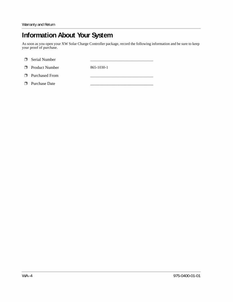
Warranty and Return
Information About Your SystemAs soon as you open your XW Solar Charge Controller package, record the following information and be sure to keep your proof of purchase.
❐ Serial Number _________________________________
❐ Product Number 865-1030-1
❐ Purchased From _________________________________
❐ Purchase Date _________________________________
WA–4 975-0400-01-01
Index
Aabsorption charging stage 1–5advanced menus 3–3alarms using auxiliary output 1–9auxiliary output functions 1–9auxiliary output menu 3–12
Bbasic menus 3–3battery equalization 4–13battery menu 3–5battery safety information vbattery temperature compensation 1–8, 3–10bulk charging stage 1–4
Ccharge stages 1–4, 4–5communication between multiple inverters 2–18current rating 2–10custom battery menu 3–8Customer Service
preparing to call WA–4
Ddaily logs 4–11default settings, resetting to 3–20, B–8device menu 3–18display menu 3–16down arrow button 3–2, B–2
Eenter button 3–2, B–2equalization
definition 1–8manual 4–14recommended frequency 4–13
exit button 3–2, B–2
Ffaults and warnings menu 4–8float charging stage 1–5
Gground fault protection fuse
replacing 5–3grounding 2–7
Hhistory menu 4–11
Iinformation about your system form WA–4input menu 3–11
Kknockouts
locations and dimensions 2–6removing 2–5
LLCD operating screens 4–2load control 1–9logged operating data 4–11
Mmenu maps 3–4, B–8, B–9menus, basic and advanced formats 3–3meters screen B–11monthly logs 4–11multiple inverters
communication between 2–18
Pparallel configuration
communication between inverters 2–18proof of purchase WA–4purchase date WA–4
Rreset menu 3–20restore default settings B–8
975-0400-01-01 IX-1

Index
Ssafety instructions vserial number WA–4silent float charging stage 1–7system control panel
buttons described B–2changing settings B–5charge controller home screen B–10meters screen B–11select device menu B–4, B–5startup screen B–4system home screen B–4
Tthree-stage charging 1–4Troubleshooting 5–2two-stage charging 1–7
Uup arrow button 3–2, B–2
Vvent fan 1–9
Wwarranty
out of warranty service WA–3terms and conditions WA–1
wire size 2–10
XXantrex
web site iv
IX–2 975-0400-01-01

Xantrex Technology Inc.
+ 34 902.10.18.13 Tel1 866 519 1470 (toll free North America)+ 34 93.305.50.26 Fax1 604 422 2756 North [email protected]@xantrex.comwww.xantrex.com
975-0400-01-01 Printed in China