Embed Size (px)
Citation preview
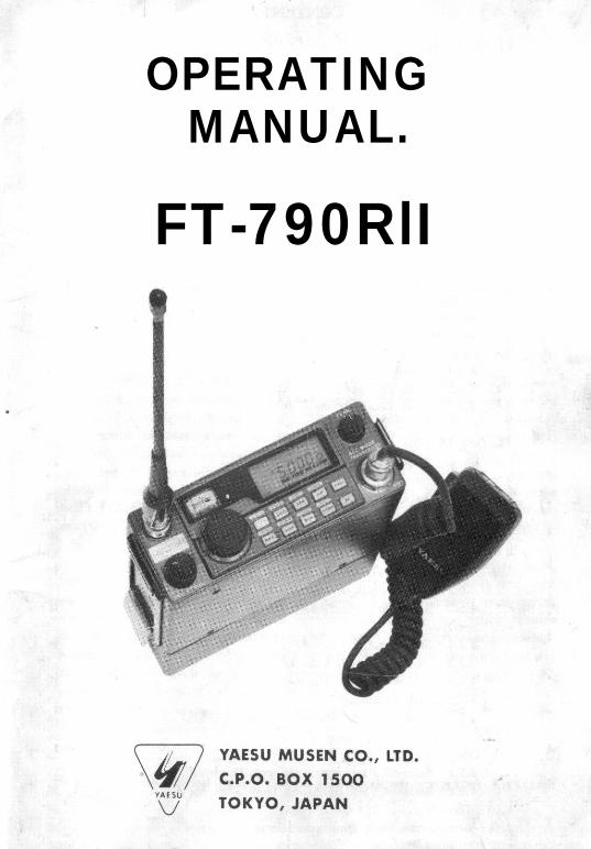
OPERATINGMANUAL.
FT-790RlI
Cf NI’I~:N’I’S
01. SPECIFICATIONS , , , , , , , , . . . . . .I.1 01 NI:Rhl.I.2 RI:CI’:IVI;R
I.3 l’I~ANCMI’l’TI:I~
1 . 4 surrl.w:n ~c~cmm~t~rs
1.5 OPTIONS
82. C O N T R O L S & C O N N E C T O R S , , (
2 . 1 FRONT PANEL
2.2 REAR PANEL
2 .3 FBA-6 BATTERY CASE
2 . 4 F L - 7 0 2 5 L I N E A R A M P L I F I E R
S3. I N S T A L L A T I O N & ACCESSORlES .
3.1 Portable Station Setup
3.2 Mobile Installation
3.3 Base Station Installation
3.4 FTS-7 Tone Squelch
3.4.1 Installation
3.4.2 Tone Frequency Selection
3.4.3 Tone Level Adjustment
84. OPERATION . . . . . . . . . . . . . . . . . . .
4.1 Squelch Setup and Tuning
4.2 Mode Selection
4.3 FM Operation
4.4 SSB Operation
4.5 cw operation
4.6 Memory Operation
4.6.1 A l t e r n a t e V F O
4.6.2 CALL Channel (Versions A and X only)
4.6.3 Standard Memories
4.7 Scanning
4.7.1 Stopping the Scanner
4.7.2 VFO (all band) scanning:
4.7.3 Stored memory channel scanning:4.7.4 Skip Scanning
4.7.5 Programmable Memory Scanning (PMS)
4.8 Priority Channel Checking
4.9 Odd Split Operation
4.9.1 Semi-DUPlex operation with Dual VFOs:
4.9.2 Semi-DUPlex operation from a memory:
4.10 Tone Squelch and Tone Burst
4.11 Getting the Most from your Batteries
4.12 Memory Backup
. 2
2
2
3
4
4
6
6
12
13
I6
. 16
18
20
22
24
24
25
25
. . 2626
27
27
28
29
30
30
30
31
3’2
33
33
33
33
34
34
35
35
3fi
36
37
R X
-l
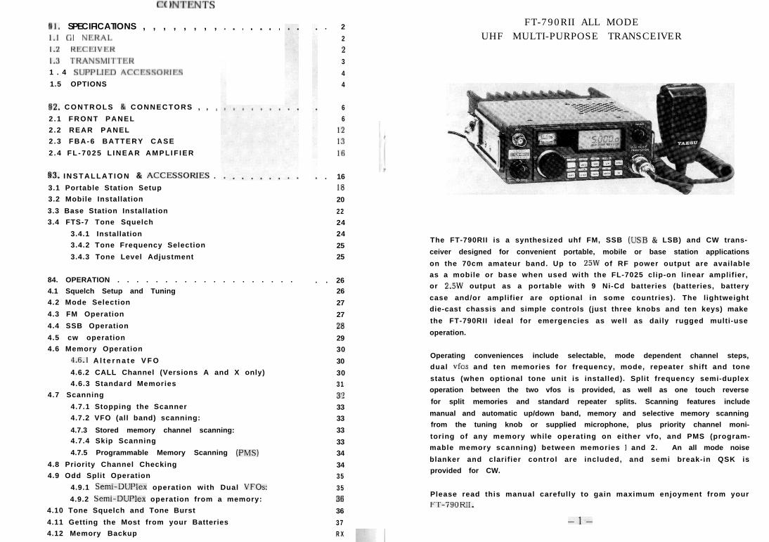
FT-790RII ALL MODEUHF MULTI-PURPOSE TRANSCEIVER
The FT-790RII is a synthesized uhf FM, SSB (USB & LSB) and CW trans-
ceiver designed for convenient portable, mobile or base station applications
on the 70cm amateur band. Up to 25W of RF power output are available
as a mobile or base when used with the FL-7025 clip-on linear amplifier,
or 2.5W output as a portable with 9 Ni-Cd batteries (batteries, battery
case and/or amplifier are optional in some countries). The lightweight
die-cast chassis and simple controls (just three knobs and ten keys) make
the FT-790RII ideal for emergencies as well as daily rugged multi-use
operation.
Operating conveniences include selectable, mode dependent channel steps,
dual vfos and ten memories for frequency, mode, repeater shift and tone
status (when optional tone unit is installed). Split frequency semi-duplex
operation between the two vfos is provided, as well as one touch reverse
for split memories and standard repeater splits. Scanning features include
manual and automatic up/down band, memory and selective memory scanning
from the tuning knob or supplied microphone, plus priority channel moni-
toring of any memory while operating on either vfo, and PMS (program-
mable memory scanning) between memories 1 and 2. An all mode noise
blanker and clarifier control are included, and semi break-in QSK is
provided for CW.
Please read this manual carefully to gain maximum enjoyment from yourFT-790RII.
-l-
8 I. SI’I~‘CIFICATIONS
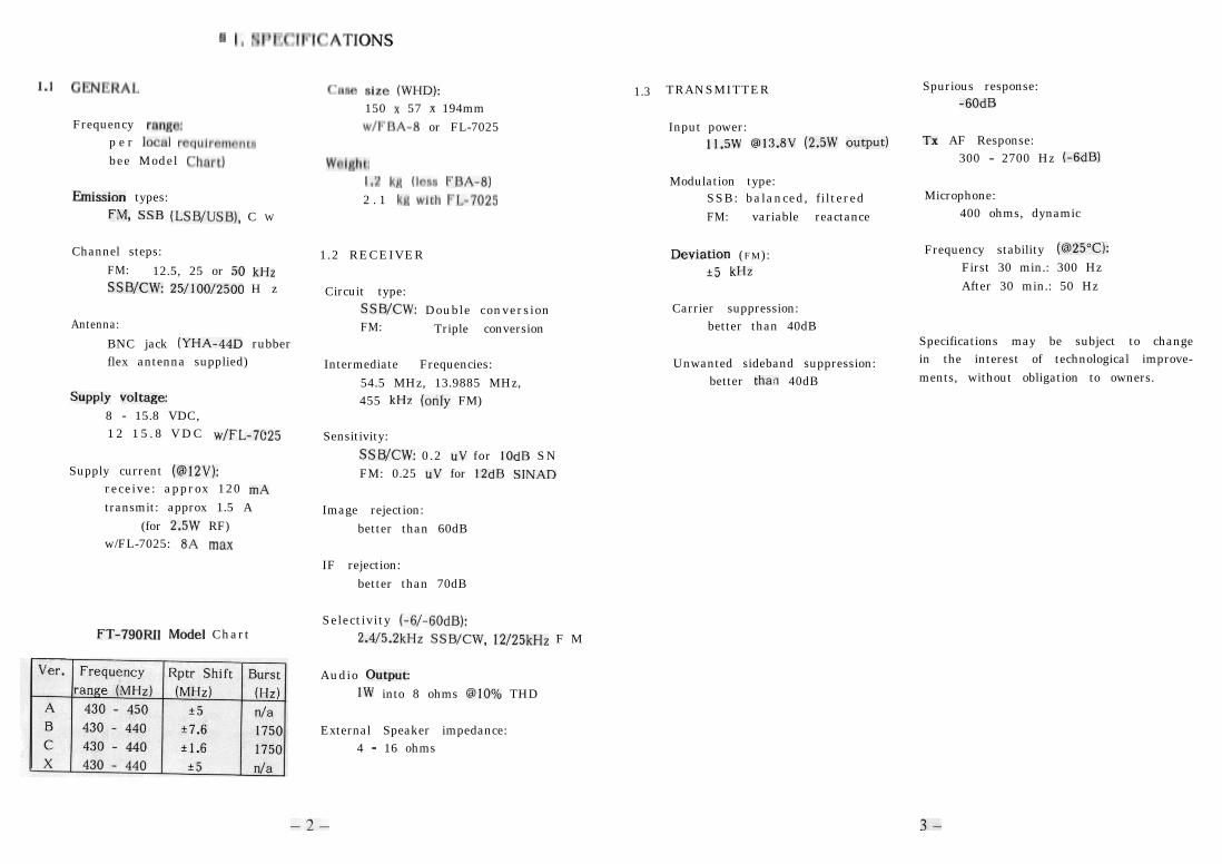
1.1 CENtVIAL
Frequency ran8n:p e r locnl rrqulrnmrntsbee Model Chnrr)
hission types:
FM, SSB (LSB/USB), C W
Channel steps:FM: 12.5, 25 or 50 kHzSSWCW: 25/100/2500 H z
Antenna:
BNC jack (YHA-44D rubberflex antenna supplied)
Supply voltage:8 - 15.8 VDC,1 2 1 5 . 8 V D C w/FL-7025
Supply current (@l2V):receive: approx 120 mAtransmit: approx 1.5 A
(for 2.5W RF)w/FL-7025: 8A max
FT-790RII Model Chart
f’nm s12e (WHD): 1.3150 x 57 x 194mmwlFl+I-8 or FL-7025
Wnl8htI,7 kg lhn FIJA-8)2 . 1 kfl with t’l,-7025
1.2 RECEIVER
Circuit type:SSWCW: Double conversionFM: Triple conversion
Intermediate Frequencies:54.5 MHz, 13.9885 MHz,455 kHz (only FM)
Sensitivity:
ssB/cw: 0.2 UV for IOdB SNFM: 0.25 uV for 12dB SINAD
Image rejection:better than 60dB
IF rejection:better than 70dB
Selectivity (-6/-60dB):2.415.2kHz SSBKW, 12/25kHz F M
Audio OutputIW into 8 ohms @IO% THD
External Speaker impedance:4 - 16 ohms
-2-
TRANSMITTER
Input power:11.5w @13.8V (2.5W output)
Modulation type:SSB: balanced, filteredFM: variable reactance
kmi0n (FM):+5 kHz
Carrier suppression:better than 40dB
Unwanted sideband suppression:better tha:? 40dB
Spurious response:-6OdB
TX AF Response:300 - 2700 Hz (-6dB)
Microphone:400 ohms, dynamic
Frequency stability (@25”C):First 30 min.: 300 HzAfter 30 min.: 50 Hz
Specifications may be subject to changein the interest of technological improve-ments, without obligation to owners.
3-
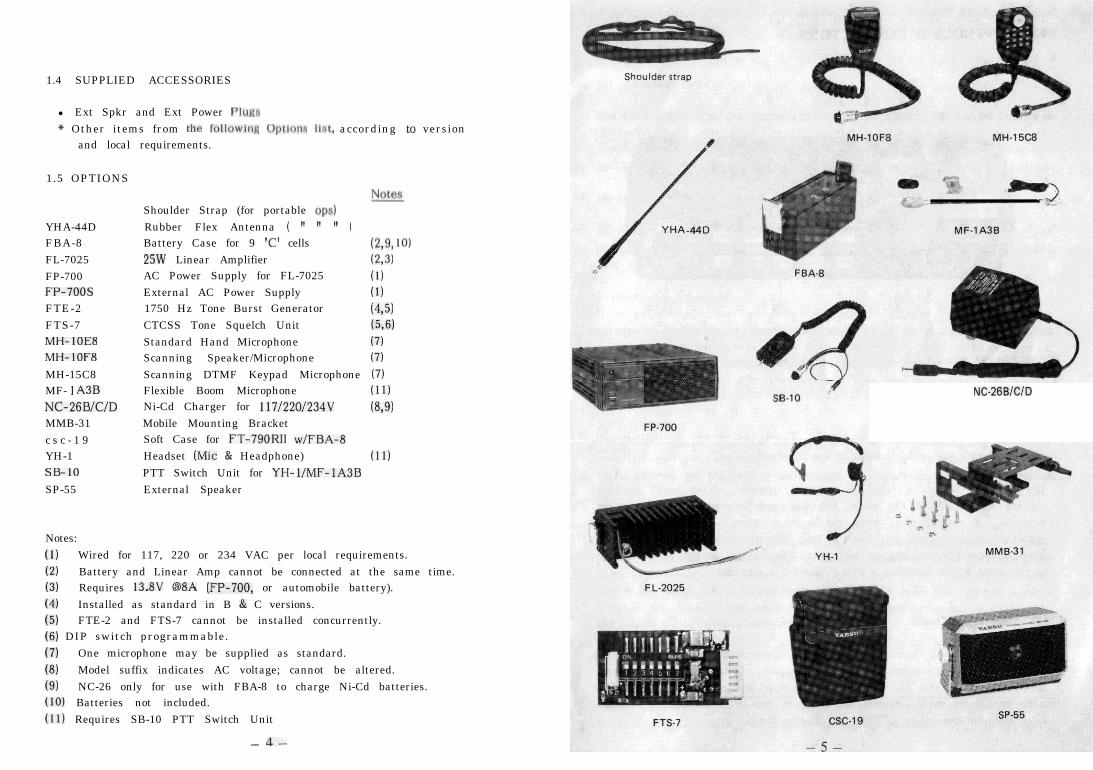
1.4 SUPPLIED ACCESSORIES
l Ext Spkr and Ext Power Pluna* Other items from the fullowln~ Optlona Ilnt, according to version
and local requirements.
1.5 OPTIONS
Shoulder Strap (for portable ops)YHA-44D Rubber Flex Antenna ( ” ” ” )FBA-8 Battery Case for 9 ‘C’ cells r&9, IO)FL-7025 25W Linear Amplifier (2.3)FP-700 AC Power Supply for FL-7025 (1)FP-700s External AC Power Supply (1)FTE-2 1750 Hz Tone Burst Generator (4.5)FTS-7 CTCSS Tone Squelch Unit (5,6)MH-lOE8 Standard Hand Microphone (7)MH-IOFB Scanning Speaker/Microphone (7)MH-15C8 Scanning DTMF Keypad Microphone (7)MF- 1 A3B Flexible Boom Microphone (11)NG26BlCID Ni-Cd Charger for 117/220/234V (69)MMB-31 Mobile Mounting Bracketc s c - 1 9 Soft Case for FT-790RlI w/FBA-8YH-1 Headset (Mic & Headphone) (11)SB-IO PTT Switch Unit for YH-l/MF-lA3BSP-55 External Speaker
Notes:(I) Wired for 117, 220 or 234 VAC per local requirements.(2) Battery and Linear Amp cannot be connected at the same time.(3) Requires 13.8V @BA (FP-700, or automobile battery).(4) Installed as standard in B & C versions.(5) FTE-2 and FTS-7 cannot be installed concurrently.(6) DIP switch programmable.(7) One microphone may be supplied as standard.(8) Model suffix indicates AC voltage; cannot be altered.(9) NC-26 only for use with FBA-8 to charge Ni-Cd batteries.(10) Batteries not included.(11) Requires SB-10 PTT Switch Unit
- A-
NC-26BICID
52. CONTROLS & CONNECTORS
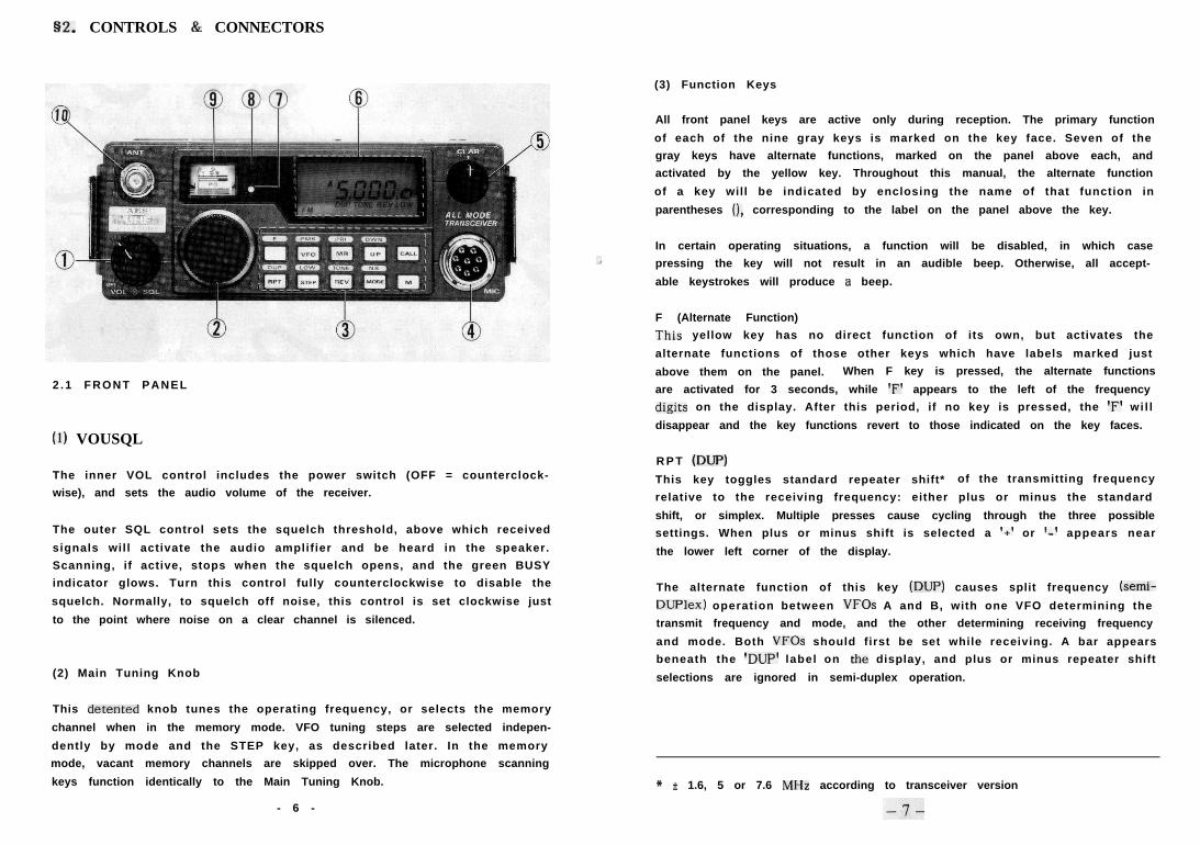
2 .1 FRONT PANEL
(I) VOUSQL
The inner VOL control includes the power switch (OFF = counterclock-
wise), and sets the audio volume of the receiver.
The outer SQL control sets the squelch threshold, above which received
signals will activate the audio amplifier and be heard in the speaker.
Scanning, if active, stops when the squelch opens, and the green BUSY
indicator glows. Turn this control fully counterclockwise to disable the
squelch. Normally, to squelch off noise, this control is set clockwise just
to the point where noise on a clear channel is silenced.
(2) Main Tuning Knob
This detented knob tunes the operating frequency, or selects the memory
channel when in the memory mode. VFO tuning steps are selected indepen-
dently by mode and the STEP key, as described later. In the memory
mode, vacant memory channels are skipped over. The microphone scanning
keys function identically to the Main Tuning Knob.
- 6 -
(3) Function Keys
All front panel keys are active only during reception. The primary function
of each of the nine gray keys is marked on the key face. Seven of the
gray keys have alternate functions, marked on the panel above each, and
activated by the yellow key. Throughout this manual, the alternate function
of a key will be indicated by enclosing the name of that function in
parentheses 0, corresponding to the label on the panel above the key.
In certain operating situations, a function will be disabled, in which case
pressing the key will not result in an audible beep. Otherwise, all accept-
able keystrokes will produce a beep.
F (Alternate Function)
This yellow key has no direct function of its own, but activates the
alternate functions of those other keys which have labels marked just
above them on the panel. When F key is pressed, the alternate functions
are activated for 3 seconds, while ‘F’ appears to the left of the frequency
digits on the display. After this period, if no key is pressed, the ‘F’ wi l l
disappear and the key functions revert to those indicated on the key faces.
R P T (DUP)
This key toggles standard repeater shift* of the transmitting frequency
relative to the receiving frequency: either plus or minus the standard
shift, or simplex. Multiple presses cause cycling through the three possible
settings. When plus or minus shift is selected a ‘+’ or ‘-’ appears near
the lower left corner of the display.
The alternate function of this key (DUP) causes split frequency (semi-
DUPlex) operation between VFOs A and B, with one VFO determining the
transmit frequency and mode, and the other determining receiving frequency
and mode. Both VFOs should first be set while receiving. A bar appears
beneath the ‘DUP’ label on the display, and plus or minus repeater shift
selections are ignored in semi-duplex operation.
* f 1.6, 5 or 7.6 MHz according to transceiver version
VFO (PMS)The VFO key selects the VFO mode if in the memory mode, and alternates
between VFO A and VFO B once in the VFO mode.
The alternate (PMS) function activates ‘Programmable Memory Scanning’,
between the frequencies stored in memory channels 1 and 2. Channel
numbers ‘1’ and ‘2’ both appear together at the upper left corner of the
display during PMS operation, described in detail later.
STEP (LOW)
The STEP key selects the frequency steps for tuning and scanning. In
CW and SSB modes, repeated presses of this key select 25, 100 and 2500
Hz in rotation. In FM, the steps are 12.5, 25 and 50 kHz.
The alternate (LOW) function selects high and low transmitter power.
Low power is about 1/5th of high power. When low power is selected, a
bar appears beneath the ‘LOW’ label at the lower right corner of the
display.
M R (PRI)
The MR (Memory Recall) key activates the memory mode from the VFO
mode. If already in the memory mode, the MR key is used to set a memory
channel for selective memory scanning, described in detail later. An ‘M’
appears at the upper left corner of the display and one or more channel
numbers appear along the top edge when in the memory mode.
The alternate (PRI) function activates PRlority channel checking, in which
a preselected memory is periodically checked for activity while operating
in the VFO mode, as described later.
REV (TONE)
The REVerse key exchanges the transmit and receive frequencies during
standard shift repeater operation (+ or - repeat active).
The alternate (TONE) function activates and deactivates the FTS-7 CTCSS
tone encoder/decoder, if installed. When active, a bar appears beneath
the ‘TONE’ label on the display. The TONE function is disabled when
the Tone Burst Unit (or no tone unit) is installed.
-8-
up (DWN)In the VFO mode, the UP key increments the operating frequency by I
MHz in the FM mode, or by 100 kHz in SSB or CW. Holding this key down
for more than :-second causes repeated stepping. In the memory mode,
the selected memory channel steps up one each time this key is pressed.
The alternate (DWN) functions causes the same stepping, but in the op-
posite direction.
MODE (NB)Pressing the MODE key selects FM, CW, USB and LSB operating modes,
in rotation. The selected mode is indicated at the left side of the display.
The alternate (NB) function toggles the noise blanker on and off (all
modes). When on, ‘NB’ appears near the lower left corner of the display.
C A L L
In versions without tone burst, this key instantly recalls the Call Channel
Memory, regardless of the previous operating status of the transceiver,
for simple, quick QSYing. In European versions with the FTE-2 Tone
Burst Unit installed, pressing this key causes a 1750 Hz tone to be trans-
mitted (the Call Channel Memory is not available).
M
This M’smorize key is used for writing new data into memories, as described
in the ‘Operation’ section.
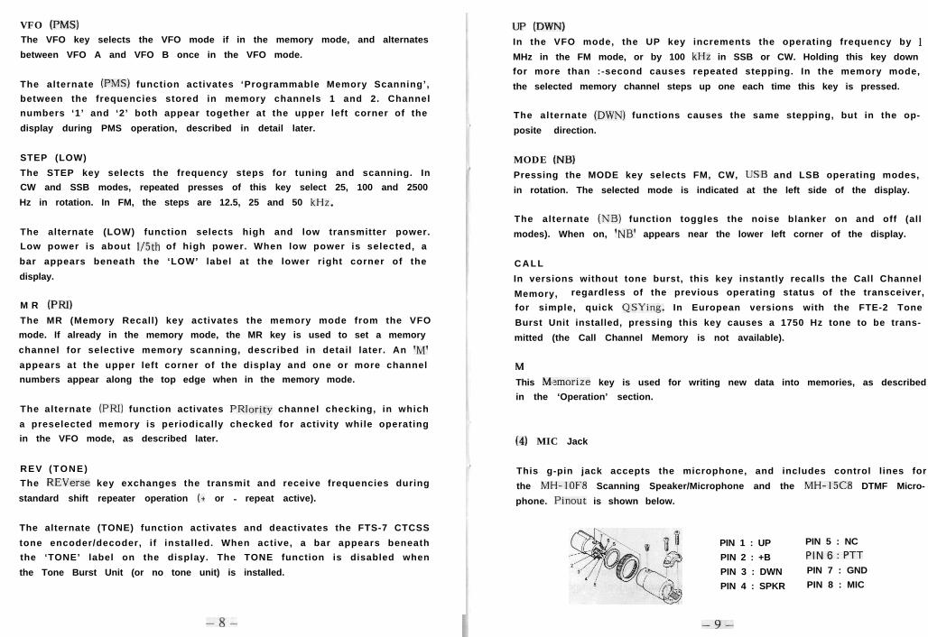
(4) MIC Jack
This g-pin jack accepts the microphone, and includes control lines for
the MH-IOFB Scanning Speaker/Microphone and the MH-l5C8 DTMF Micro-
phone. Pinout is shown below.
PIN 1 : UP PIN 5 : NC
PIN 2 : +B PIN6:PTT
PIN 3 : DWN PIN 7 : GND
PIN 4 : SPKR PIN 8 : MIC
-9-
( 5 ) C L A R C o n t r o l
T h i s (CLARifier) c o n t r o l a l l o w s a p p r o x i m a t e l y ?I kHz a d j u s t m e n t o f t h er e c e i v i n g f r e q u e n c y , f o r f i n e t u n i n g a s i g n a l , e s p e c i a l l y i n S S B a n d C Wm o d e s . R e m e m b e r t o s e t t h i s c o n t r o l a t t h e c e n t e r d e t e n t f o r p r o p e rfrequency display during normal tuning or scanning.
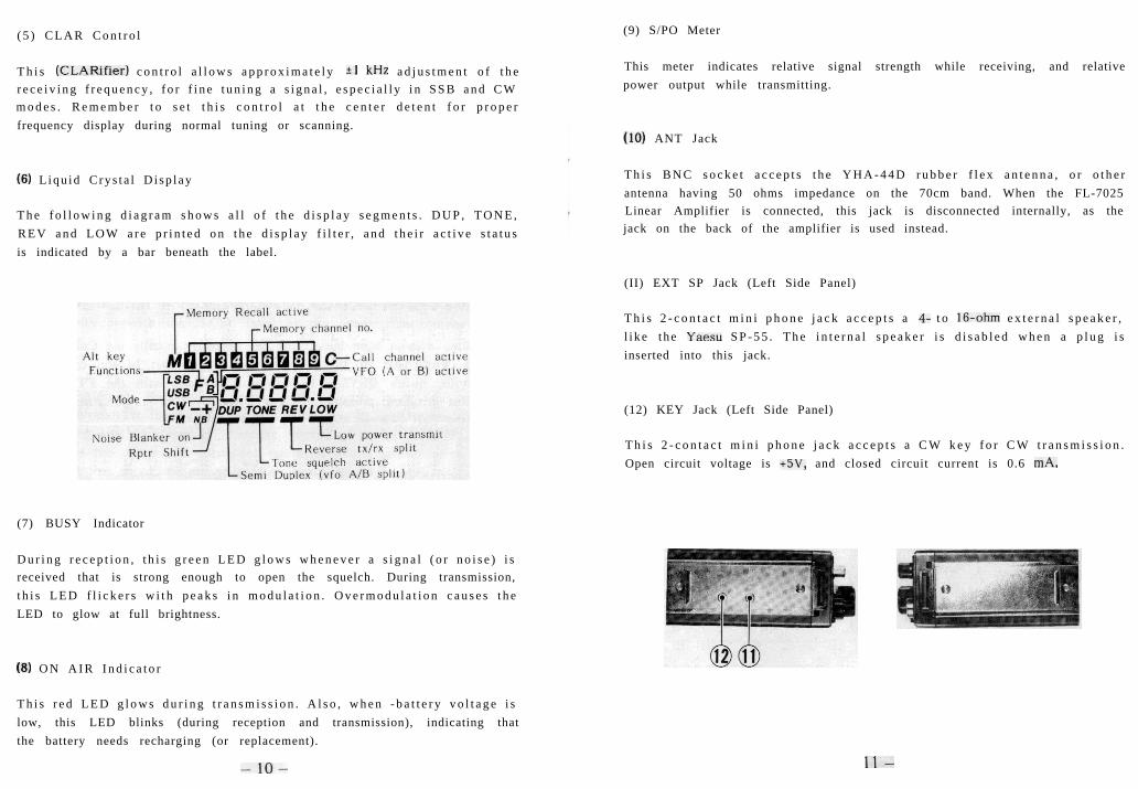
(6) L i q u i d C r y s t a l D i s p l a y
T h e f o l l o w i n g d i a g r a m s h o w s a l l o f t h e d i s p l a y s e g m e n t s . D U P , T O N E ,R E V a n d L O W a r e p r i n t e d o n t h e d i s p l a y f i l t e r , a n d t h e i r a c t i v e s t a t u sis indicated by a bar beneath the label.
(7) BUSY Indicator
D u r i n g r e c e p t i o n , t h i s g r e e n L E D g l o w s w h e n e v e r a s i g n a l ( o r n o i s e ) i sreceived that is strong enough to open the squelch. During transmission,t h i s L E D f l i c k e r s w i t h p e a k s i n m o d u l a t i o n . O v e r m o d u l a t i o n c a u s e s t h eLED to glow at full brightness.
(8) O N A I R I n d i c a t o r
T h i s r e d L E D g l o w s d u r i n g t r a n s m i s s i o n . A l s o , w h e n - b a t t e r y v o l t a g e i slow, this LED blinks (during reception and transmission), indicating thatthe battery needs recharging (or replacement).
-lO-
(9) S/PO Meter
This meter indicates relative signal strength while receiving, and relativepower output while transmitting.
(IO) ANT Jack
T h i s B N C s o c k e t a c c e p t s t h e Y H A - 4 4 D r u b b e r f l e x a n t e n n a , o r o t h e rantenna having 50 ohms impedance on the 70cm band. When the FL-7025Linear Amplifier is connected, this jack is disconnected internally, as thejack on the back of the amplifier is used instead.
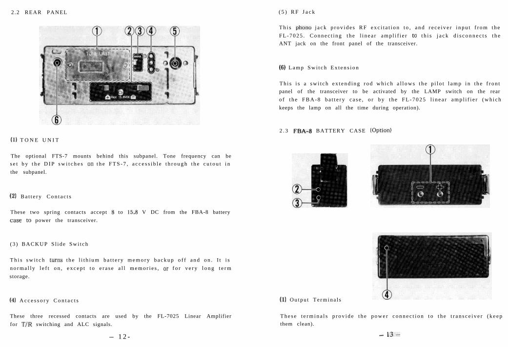
(II) EXT SP Jack (Left Side Panel)
T h i s 2 - c o n t a c t m i n i p h o n e j a c k a c c e p t s a 4- t o 16-ohm e x t e r n a l s p e a k e r ,l i ke t he Yaesu S P - 5 5 . T h e i n t e r n a l s p e a k e r i s d i s a b l e d w h e n a p l u g i sinserted into this jack.
(12) KEY Jack (Left Side Panel)
T h i s 2 - c o n t a c t m i n i p h o n e j a c k a c c e p t s a C W k e y f o r C W t r a n s m i s s i o n .Open circuit voltage is +5V, and closed circuit current is 0.6 mA.
ll-
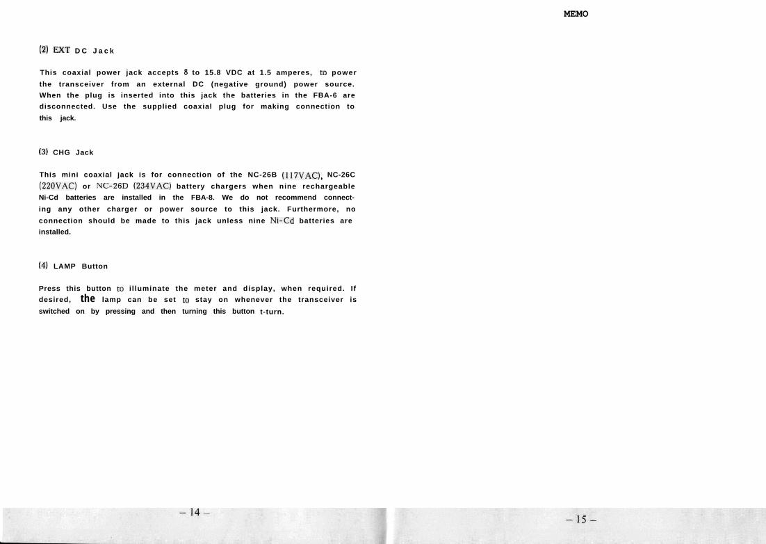
2 .2 REAR PANEL
(1) T O N E U N I T
The optional FTS-7 mounts behind this subpanel. Tone frequency can bes e t b y t h e D I P s w i t c h e s on t h e F T S - 7 , a c c e s s i b l e t h r o u g h t h e c u t o u t i nthe subpanel.
(2) B a t t e r y C o n t a c t s
These two spring contacts accept 8 to 15.8 V DC from the FBA-8 batterycase to power the transceiver.
( 3 ) B A C K U P S l i d e S w i t c h
T h i s s w i t c h turns t h e l i t h i u m b a t t e r y m e m o r y b a c k u p o f f a n d o n . I t i sn o r m a l l y l e f t o n , e x c e p t t o e r a s e a l l m e m o r i e s , or f o r v e r y l o n g t e r mstorage.
(4) A c c e s s o r y C o n t a c t s
These three recessed contacts are used by the FL-7025 Linear Amplifierfor T/R switching and ALC signals.
- 12-
( 5 ) R F J a c k
T h i s phone j a c k p r o v i d e s R F e x c i t a t i o n t o , a n d r e c e i v e r i n p u t f r o m t h eF L - 7 0 2 5 . C o n n e c t i n g t h e l i n e a r a m p l i f i e r to t h i s j a c k d i s c o n n e c t s t h eANT jack on the front panel of the transceiver.
(6) L a m p S w i t c h E x t e n s i o n
T h i s i s a s w i t c h e x t e n d i n g r o d w h i c h a l l o w s t h e p i l o t l a m p i n t h e f r o n tpanel of the transceiver to be activated by the LAMP switch on the rearo f t h e F B A - 8 b a t t e r y c a s e , o r b y t h e F L - 7 0 2 5 l i n e a r a m p l i f i e r ( w h i c hkeeps the lamp on all the time during operation).
2 . 3 FBA-8 BATTERY CASE (Option)
(1) O u t p u t T e r m i n a l s
T h e s e t e r m i n a l s p r o v i d e t h e p o w e r c o n n e c t i o n t o t h e t r a n s c e i v e r ( k e e pthem clean).
- 13-
MEMO
(2) FXT D C J a c k
This coaxial power jack accepts 8 to 15.8 VDC at 1.5 amperes, to power
the transceiver from an external DC (negative ground) power source.
When the plug is inserted into this jack the batteries in the FBA-6 are
disconnected. Use the supplied coaxial plug for making connection to
this jack.
(3) CHG Jack
This mini coaxial jack is for connection of the NC-26B (II’IVAC), NC-26C
(220VAC) or NC-ED (234VAC) battery chargers when nine rechargeable
Ni-Cd batteries are installed in the FBA-8. We do not recommend connect-
ing any other charger or power source to this jack. Furthermore, no
connection should be made to this jack unless nine N&Cd batteries are
installed.
(4) LAMP Button
Press this button to i l luminate the meter and display, when required. I f
desired, the lamp can be set to stay on whenever the transceiver is
switched on by pressing and then turning this button t-turn.
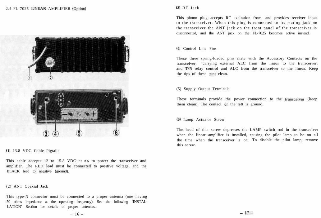
2.4 FL-7025 LlNEAR AMPLIFIER (Option)
(1) 13.8 VDC Cable Pigtails
This cable accepts 12 to 15.8 VDC at BA to power the transceiver andamplifier. The RED lead must be connected to positive voltage, and theBLACK lead to negative (ground).
(2) ANT Coaxial Jack
This type-N connector must be connected to a proper antenna (one having50 ohms impedance at the operating frequency). See the following ‘INSTAL-LATION’ Section for details of proper antennas.
- 16 -
(31 RF Jack
This phono plug accepts RF excitation from, and provides receiver inputto the transceiver. When this plug is connected to i ts mating jack onthe transceiver the ANT jack on the front panel of the transceiver isdisconnected, and the ANT jack on the FL-7025 becomes active instead.
(4) Control Line Pins
These three spring-loaded pins mate with the Accessory Contacts on thetransceiver, carrying external ALC from the linear to the transceiver,and T/R relay control and ALC from the transceiver to the linear. Keepthe tips of these pins clean.
(5) Supply Output Terminals
These terminals provide the power connection to the transceiver (keepthem clean). The contact on the left is ground.
6) Lamp Actuator Screw
The head of this screw depresses the LAMP switch rod in the transceiverwhen the linear amplifier is installed, causing the pilot lamp to be on allthe time when the transceiver is on. To disable the pilot lamp, removethis screw.
- 17-
‘83. INSTALLATION & ACCESSORIES
The FT-790RlI is designed for use as either a portable, mobile or basestation, according to which accessories are used with the transceiver.Your FT.790RII will have been supplied with certain accessories for eitherportable or mobile operation. Contact your Yaesu dealer if you requireother options.
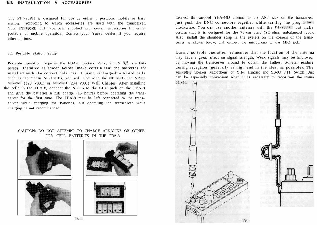
3.1 Portable Station Setup
Portable operation requires the FBA-8 Battery Pack, and 9 ‘C’ size bat-ter1es, instal led as shown below (make certain that the bat ter ies areinstalled with the correct polari ty). If using rechargeable Ni-Cd cellssuch as the Yaesu NC-1800’s, you will also need the NC-26B (117 VAC),NC-XC (220 VAC) or NC-26D (234 VAC) Wall Charger. After installing
the cells in the FBA-8, connect the NC-26 to the CHG jack on the FBA-8and give the batteries a full charge (15 hours) before operating the trans-ceiver for the first time. The FBA-8 may be left connected to the trans-ceiver while charging the batteries, but operating the transceiver whilecharging is not recommended.
.
CAUTION: DO NOT ATTEMPT TO CHARGE ALKALINE OR OTHERDRY CELL BATTERIES IN THE FBA-8.
18-
Connect the supplied YHA-44D antenna to the ANT jack on the transceiver:just push the BNC connectors together while turning the plug i-turnclockwise. You can use another antenna with the FT-790RII, but makecertain that it is designed for the 70-cm band (SO-ohm, unbalanced feed).Also, install the shoulder strap in the eyelets on the comers of the trans-ceiver as shown below, and connect the microphone to the MIC jack.
During portable operation, remember that the location of the antennamay have a great affect on signal strength. Weak signals may be improvedby moving the transceiver around to obtain the highest S-meter readingduring reception (generally as high and in the clear as possible). TheMH-IOFB Speaker Microphone or YH-I Headset and SB-IO PTT Switch Unitcan be especially convenient when it is necessary to reposition the trans-
3.2 Mobile Installation
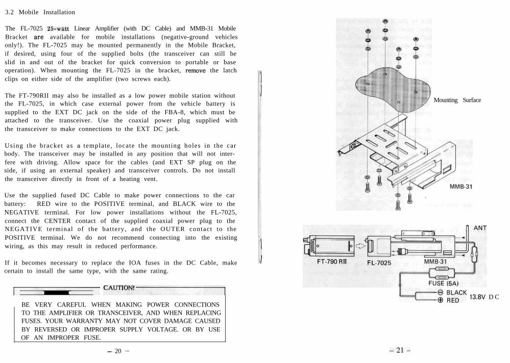
The FL-7025 25-watt Linear Amplifier (with DC Cable) and MMB-31 MobileBracket are available for mobile installations (negative-ground vehiclesonly!). The FL-7025 may be mounted permanently in the Mobile Bracket,if desired, using four of the supplied bolts (the transceiver can still beslid in and out of the bracket for quick conversion to portable or baseoperation). When mounting the FL-7025 in the bracket, remove the latchclips on either side of the amplifier (two screws each).
The FT-790RII may also be installed as a low power mobile station withoutthe FL-7025, in which case external power from the vehicle battery issupplied to the EXT DC jack on the side of the FBA-8, which must beattached to the transceiver. Use the coaxial power plug supplied withthe transceiver to make connections to the EXT DC jack.
Using the bracket as a template, locate the mounting holes in the carbody. The transceiver may be installed in any position that will not inter-fere with driving. Allow space for the cables (and EXT SP plug on theside, if using an external speaker) and transceiver controls. Do not installthe transceiver directly in front of a heating vent.
Use the supplied fused DC Cable to make power connections to the carbattery: RED wire to the POSITIVE terminal, and BLACK wire to theNEGATIVE terminal. For low power installations without the FL-7025,connect the CENTER contact of the supplied coaxial power plug to theNEGATIVE terminal of the battery, and the OUTER contact to thePOSITIVE terminal. We do not recommend connecting into the existingwiring, as this may result in reduced performance.
If it becomes necessary to replace the IOA fuses in the DC Cable, makecertain to install the same type, with the same rating.
CAUT1oN!’
BE VERY CAREFUL WHEN MAKING POWER CONNECTIONSTO THE AMPLIFIER OR TRANSCEIVER, AND WHEN REPLACINGFUSES. YOUR WARRANTY MAY NOT COVER DAMAGE CAUSEDBY REVERSED OR IMPROPER SUPPLY VOLTAGE. OR BY USEOF AN IMPROPER FUSE.
Mounting Surface
“““““““““““““““““““” “,‘;“,“” 13.8V D C
- 20 - -2l-
Connect your antenna feedline to the type-N coaxial jack on the back ofthe FL-7025. Use the shortest practical length of 50.ohm coax for thefeedline, with a type-N plug at the transceiver end. The antenna shouldbe one specifically designed for the 70.cm amateur band. Make sure theantenna mounting bracket is well grounded to the car body at the baseof the antenna.
Note: The BNC antenna jack on the front panel of the transceiver isautomatically disconnected when the FL-7025 is connected.
Slide the transceiver into the bracket carefully until the small catch atthe front corner clicks. Press the catch and pull to remove the transceiver.
The optional SP-55 External Speaker (with swivel mount) is recommendedfor mobile operation with the FT-790RII. Mount the SP-55 in a convenientlocation, and connect it to the EXT SP jack on the side of the transceiver.The optional MF-IA3B Flexible Boom Microphone adds further conveniencein mobile operation. Mount the MF-IA38 so that the microphone elementcan be positioned near your mouth when driving, and connect it via theS&IO PTT Switch Unit to the MIC jack.
3.3 Base Station Installation
The FT-790RII may be used as a base station with or without the FL-7025Linear Amplifier. For low power operation without the FL-7025, use theFP-700s AC Power Supply, connected to the EXT DC jack using the sup-plied coaxial power plug (CENTER contact NEGATIVE, OUTER contactPOSITIVE). Make certain that the FP-700s is wired for your local ACline voltage before connecting it to the AC mains. The FP-700s will notcharge the batteries in the FBA-8; use the NC-26 for this purpose.
For high power base station operation with the FL-7025, use the fused(IOA) DC cable supplied with the Linear Amplifier. We recommend theFP-700 Power Supply, or an equivalent providing 13.8 VDC at IOA contin-uously. Connect the RED power lead to the POSITIVE supply terminal,and the BLACK lead to the NEGATIVE terminal.
Do not place the transceiver on top of another heat generating device.
- 22 -
If using the FL-7025, keep the area around the hearsink clear, to permitthe free flow of air for cooling.
Connect your antenna feedline to the type-N coaxial jack on the back ofthe FL-7025. Use the shortest practical length of 50-ohm coax for thefeedline, with a type-N plug at the transceiver end. The antenna shouldbe one specifically designed for the 70-cm amateur band.
Note: The BNC antenna jack on the front panel of the transceiver isautomatically disconnected when the FL-7025 is connected.
For CW operation, connect your key to the KEY jack on the side of thetransceiver. A plug is provided for this purpose.
The SP-55 External Speaker, mentioned in the previous section, is also aconvenient addition to base installstlons.
- 23 -
3.4 FTS-7 Tone Squelch
The FTS-7 is a DIP-switch programmable subaudible tone generator anddecoder that provides tone squelch operation using the operator’s choiceof 37 standard subaudible (CTCSS) tones, for silent channel monitoringand operation through CTCSS-equipped repeaters. The FTS-7 can be instal-led only in transceivers in which the FTE-2 Tone Burst Unit is not alreadyinstalled. Operation is described in 54.10.
3.4.1 installation
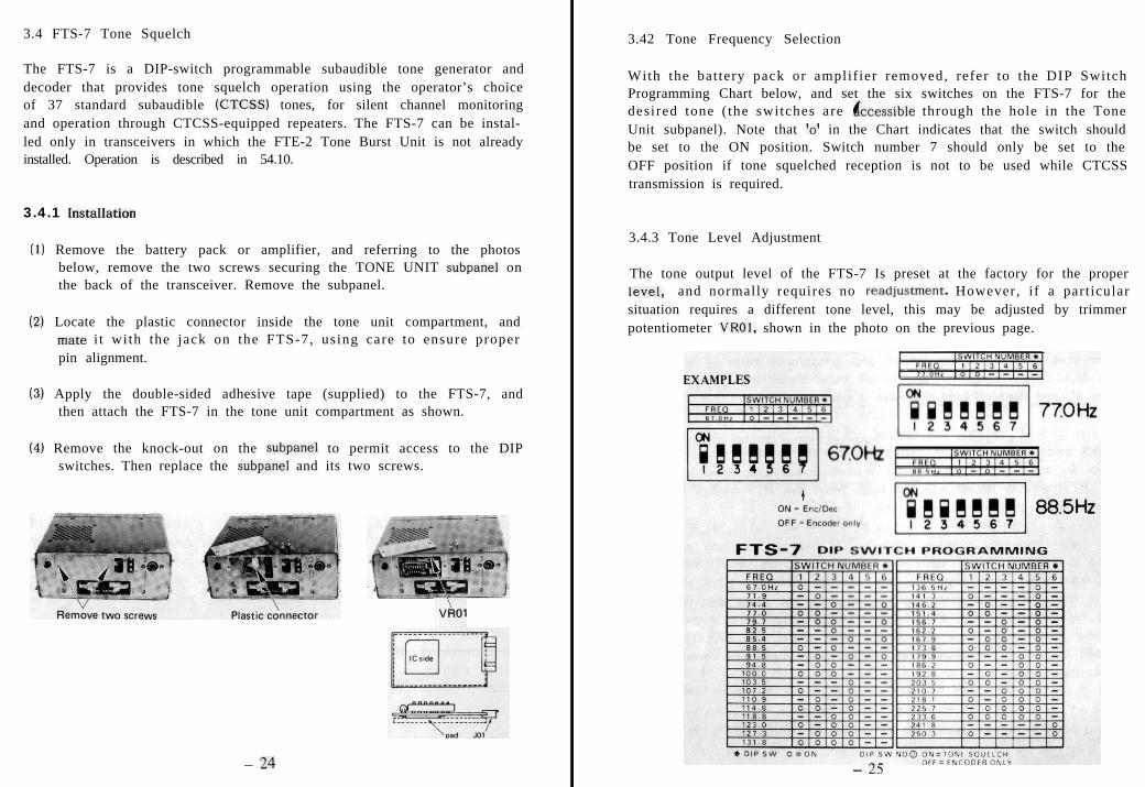
(1) Remove the battery pack or amplifier, and referring to the photosbelow, remove the two screws securing the TONE UNIT subpanel onthe back of the transceiver. Remove the subpanel.
(2) Locate the plastic connector inside the tone unit compartment, andmate i t with the jack on the FTS-7, using care to ensure properpin alignment.
(3) Apply the double-sided adhesive tape (supplied) to the FTS-7, andthen attach the FTS-7 in the tone unit compartment as shown.
(4) Remove the knock-out on the subpanel to permit access to the DIPswitches. Then replace the subpanel and its two screws.
- 24
3.42 Tone Frequency Selection
With the bat tery pack or amplif ier removed, refer to the DIP SwitchProgramming Chart below, and set the six switches on the FTS-7 for thedesired tone ( the switches are &cessible through the hole in the ToneUnit subpanel). Note that ‘0’ in the Chart indicates that the switch shouldbe set to the ON position. Switch number 7 should only be set to theOFF position if tone squelched reception is not to be used while CTCSStransmission is required.
3.4.3 Tone Level Adjustment
The tone output level of the FTS-7 Is preset at the factory for the properlWC!l, and normally requires no road]ustment. However, i f a part icularsituation requires a different tone level, this may be adjusted by trimmerpotentiometer VROI, shown in the photo on the previous page.
- 25
54. OPERATION
Before switching on the transceiver, check to ensure that the antenna,microphone and battery pack (or external power source) are properlyconnected. Preset the SQL control ful ly counterclockwise, and theCLARlFIER to its center detent.
4.1 Squelch Setup and Tuning
Turn on the transceiver by rotating the VOL control clockwise out ofthe click-stop. The green BUSY indicator should light, while the displayshows the last three, four or five digits of your receiving frequency(beginning with I’s of MHz and a decimal point). Advance the VOL controlfor comfortable volume on a signal or noise.
Press the VFO key to select VFO operation, and use the tuning knob totune to a clear frequency (where only background noise Is heard). Turnthe SQL Control clockwise just to the point where the green BUSY lampgoes off and stays off (and the noise is silenced).
If you have a scanning microphone, try tuning with the microphone UP-/DWN buttons, press either button momentarily to single step, or hold itdown for manual scanning.To stop, release it and then press it again (orthe PTT switch) momentarily to halt . When the PTT switch is used tohalt scanning, no transmission occurs.
For ‘large frequency changes, such as for moving from one part of theband to another, ‘giant’ steps are available via the UP (DOWN) key onthe front panel. Just press this key once to take one giant step up, orpress the F key and then this key to take one giant s tep down. Holdthis key for more than a half-second for multiple giant steps (and justrelease it to stop). Giant steps are 1 MHz in FM, and 100 kHz in othermodes; except at the band edges, where lesser digits are rounded to thenearest giant step.
- 26 -
4.2 Mode Selection
Press the MODE key while observing the display of operating mode atthe left side of the display. Each time this key is pressed the mode willchange, in this order: FM - CW - USB - LSB and back to FM. Theselected mode will be retained when power is switched off.
4.3 FM Operation
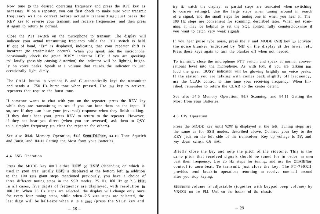
Press the MODE key until ‘FM’ is displayed at the bottom left. In additionto the I MHz giant steps mentioned above, you have a choice of threedifferent tuning steps in the FM mode: 12.5, 25 or 50 kHz. The frequencydigits displayed indicate which tuning steps are currently selected: fourdigits plus a small zero or (full-size) ‘5’ when 12.5 kHz steps are selected,just four digits when 25 kHz steps are selected, and just 3 digits when50 kHz steps are selected. Press the STEP key to change tuning steps(and watch the display, as partial steps are truncated when switching tocoarser settings).
. . . . . . . MODE/STEP DISPLAYS .
A” VerS (FM)12.5 kHZ Step8
All “ers (SSB & CW)
CALL Channel IVers A)CALL Channel IVers A)
I,1
Press the RPT key three t imes while .watching.~,just to the left of the‘DUP’ label on the display: you should see I+’ and then ‘-’ appear, indi-cating plus and minus standard transmit repeater shift (1.6, 5 or 7.6 MHz,according to version) from the displayed receiving frequency. When neitheris displayed, you are set for simplex operation.
- 21-
Now tune to the desired operating frequency and press the RPT key asnecessary. If on a repeater, you can first check to make sure your transmitfrequency will be correct before actually transmitt ing; just press theREV key to reverse your transmit and receive frequencies, and then pressit again to return to normal.
Close the PTT switch on the microphone to transmit. The display willindicate your actual transmitting frequency while the PTT switch is held.If out of band, ‘Err’ is displayed, indicating that your repeater shift isincorrect (no transmission occurs). When you speak into the microphone,occasionally check the green BUSY indicator LED: if you are speakingto” loudly (possibly causing distortion) the indicator will be lighting bright-ly on voice peaks. Speak at a volume that causes the indicator to justoccasionally light dimly.
The CALL button in versions B and C automatically keys the transmitterand sends a 1750 Hz burst tone when pressed. Use this key to activaterepeaters that require the burst tone.
If someone wants to chat with you on the repeater, press the REV keywhile they are transmitting to see if you can hear them on the input. Ifso, see if they can hear your (reversed) response when they finish talking.If they don’t hear your, press REV to return to the repeater. However,if they can hear you direct (when you are reversed), ask them to QSYto a simplex frequency (to clear the repeater for others).
See also §4.6. Memory Operation, §4.9 Semi-Duplex, s4.10 Tone Squelchand Burst, and §4.11 Getting the Most from your Batteries.
4.4 SSB Operation
Press the MODE key until either ‘USB’ or ‘LSB’ (depending on which isused in your area: usually USB) is displayed at the bottom left. In additiont” the 100 kHz giant steps mentioned previously, you have a choice ofthree different tuning steps in the SSB modes: 25 Hz, 100 Hz or 2.5 kHz.In all cases, f ive digits of frequency are dlsplayed, with resolution to100 Hz. When 25 Hz steps are selected, the display will change only oncefor every four tuning steps, while when 2.5 kHz steps are selected, thelast digit will be half-size when it is a zero (press the STEP key and
- 28 -
try it: watch the display, as partial steps are truncated when switchingto coarser settings). Use the large steps when tuning around in searchof a signal, and the small steps for tuning one in when you hear it. The100 Hz steps are convenient for scanning, described later. When not scan-ning, it may be helpful to set the SQL control fully counterclockwise ifyou want to catch very weak signals.
If you hear pulse type noise, press the F and MODE (NB) key t” activatethe noise blanker, indicated by ‘NB’ on the display at the lower left .Press these keys again to turn the blanker off when not needed.
To transmit, close the microphone PTT switch and speak at normal conver-sational level into the microphone. As with FM, if you are talking to”loud the green BUSY indicator will be glowing brightly on voice peaks.If the station you are talking with comes back slightly off frequency,use the CLAR control t” fine tune your receiving frequency. When fin-ished, remember to return the CLAR to the center detent.
See also 54.6 Memory Operation, 84.7 Scanning, and 84.11 Getting theMost from vow Batteries.
4.5 CW Operation
Press the MODE key until ‘CW’ is dlsplayed at the left. Tuning steps arethe same as for SSB modes, described above. Connect your key to theKEY jack on the left side of the transceiver. Key up voltage is 5V, andkey down current 0.6 mA.
Briefly close the key and note the pitch of the sidetone. This is thesame pitch that received signals should be tuned for in order t” zerobeat their frequency. Use 25 Hz steps for tuning, and use the CLARifiercontrol to zero beat . To t ransmit , jus t c lose the key. The FT-790RIIprovides semi break-in operation; returning t” receive one-half secondafter you stop keying.
Sidetone volume is adjustable ( together with keypad beep volume) byVR4002 on the PLL Unit on the bottom of the chassis.
- 29
4.6 Memory Operation
The FT-790RII has nine standard memories plus the two vfos, which serveas special function memories. Versions A and X also have a calling channelmemory, which is recalled by the CALL key. Each stores frequency andmode, and all but the vfos also store +I- RPT setting, and tone call data(described later). The vfo memories (and the CALL memory for versionsA and X) are described first:
4.6.1 Alternate VFO
VFO B simply duplicates the VFO functions that have already been des-cribed, without affecting the other VFO (VFO A). Notice that, duringVFO operation, a small ‘A’ or ‘8’ appears just to the lef t of the fre-quency digits on the display. To switch from one VFO to another, justpress the VFO key repeatedly. In the following paragraphs, when ‘VFO’is referred to, it means either VFO A or 8.
To copy one VFO to the other:
(I) Press the VFO key to select the source VFO.(2) Press the M key followed immediately by the VFO key.
4.6.2 CALL Channel (Versions A and X only)
This special memory allows instant recall of a prestored frequency (andmode and +I-RPT setting) at any time (except when transmitting, ofcourse). Store your main operating frequency or emergency channel herefor instant recall.
To store the CALL channel:
(1) Set the VFO to the desired frequency and mode.(2) Press the RPT key if this is a repeater channel.(3) Press the M key and then the CALL key.
To recall the CALL channel just press CALL. Press CALL again to returnto your original channel.
- 30 -
4.6.3 Standard Memories
Data to be stored in the standard memories must originate in the VFO.Once stored, it is possible to change some settings temporarily and evenpermanently, or to erase the memory altogether. Be careful though, aswriting data to a memory always overwrites any previous data stored there.
To store data In a memory:
(I) Set the VFO for operatlon as desired in the memory.(2) Press the M key once, followed immediately by the UP key
to select the desired channel number for storage.(3) Press the M key agaln to stare.
Step I includes setting mode and repeater shlft (if needed), as well asfrequency: all will be stored In the memory. At step 2, when M is pressed,an ‘M’ will biink at the upper left corner of the display, together withone channel number (blinking). Other non-bllnklng channel numbers mayalso appear: these already have data stored In them. The one channelnumber that is blinking is the one aelected for storage. To select anotherchannel for storage, press the UP key on the front panel (not the mic-rophone) to step up one channel number (or F (DWN) to step down onechannel number). In this case you must press and release the key repeat-edly to move more than one channel, This selection process may requiresome practice, as you are allowed only three seconds maximum betweenkeystrokes. If the blinking ‘M’ dlssppears before you reach step 3, startagain. The time limit provides some security against accidental ovwwritingof memories.
Once you have successfully reached step 3, operation will return to theoriginal VFO, but now this same data will be available in the memory.
To recall a memory:
(I) Press the MR key.(2) Turn knob or use Mic UP/DWN keys to select memories.
During memory recall operation, an ‘M’ appears at the upper left, withthe recalled memory number to the right of it. You are free to change
-3l-
the mode or repeater shift of a recalled memory: such changes will be
temporary unless you press the M key twice to store the new settings.
Other memories that have been previously stored can be recalled by the
tuning knob, or by the UPIDWN keys on the microphone.
If you have stored a memory but do not want to have it recalled every
time you check the other memories, you can ‘hide’ it.
To delete (hide) a memory:
(I) Recall the memory channel.
(2) Press M and then MR.
The display data will disappear, and the memory will appear empty.
To recall a deleted (hidden) memory:
(I) Use the front panel UF’ key to select the memory channel.
(2) Press M and then MR.
Be careful not to overwrite hidden channels when storing new data, as
there is no way to distinguish between hidden channels and those that
are truly empty.
To return to the VFO from the memory mode, press the VFO key.
4.7 Scanning
Three types of scanning are. possible with the FT-790RII: VFO, memory
channel or PMS (Programmable Memory Scanning). In each case, scanning
is started by the UP/DWN keys on the microphone. Scanning pauses auto-
matically for five seconds when a carrier is detected by the receiver and
then resumes again automatically. If the carrier drops while the scanner
is. paused, scanning will rowme after one second (unless another carrier
appears). The decimal on the frequency display blinks while the scanner
is paused on a channel.
- 32 -
4.7.1 Stopping the Scanner
Momentarily press the UPIDWN keys or PTT switch on the microphone to
stop the scanner. Note that the normal function of these keys is suspen-
ded during scanning, so pressing them will only stop the scanner (no
transmission or further scanning will occur). To resume scanning, or to
transmit, first release the key or switch, and then press it again.
4.72 VFO (all band) scanning:
(1) Select VFO frequency and mode.
(2) Press mic UP or DWN key for I-second.
(3) Press STEP or MODE to change steps or mode.
(4) Press mic UP/DWN or PTT, or VFO key to stop.
4.7.3 Stored memory channel scannln~:
(I) Press MR if not already In Memory mode.
(2) Press mic UP or DWN key for l-second.
(3) Press mic UP/DWN or PTT. or MR key to stop.
Only the stored memories are scanned.
4.7.4 Skip Scanning
It is also possible to skip certain memory channels only when scanning.
Such channels can still be selected manually via the tuning knob or mic
UPIDWN keys, but will be Ignored by the scanner. These channels are
distinguished by a blinking channel number at top of the display (vs
solid numbers for scannable memory channels).
Skip a channel during memory scanning:
(I) Press MR if not already in Memory mode.
(2) Select channel number to skip (top of display).
(3) Press MR: channel number should start blinking.
(4) Press mic UP or DWN key for &sec to start scanning.
- 33 -
To reinstate a channel for scanning, just repeat the above steps, pres-
sing MR when the (blinking) channel number is selected; it will stop
blinking.
4.7.5 Programmable Memory Scanning (PM?,)
PMS allows you to scan just a selected portion of the band, between the
(lower) frequency stored in memory 1 and the (higher) frequency stored
in channel 2. When this PMS mode is active, channel numbers I and 2
are both displayed together at the top left, and scanning as well as manual
tuninR are limited within the selected range.
PMS (limited band) scanning:
(1) Store low edge frequency from VFO into channel 1.
(2) Store high edge frequency from VFO into channel 2.
(3) Press F and then VFO IPMS): Ch nos. I & 2 both displayed.
(4) Press mic UP or DWN key for ;-set to start scanning.
(5) Press STEP or MODE to change either.
(6) Press mic buttons to stop scanning, and then VFO,
M or CALL to escape the PMS band limits.
4.8 Priority Channel Checking
While operating on a VFO, you can monitor for activity on a memory
channel. While the Priority function is active, the prlorlty memory channel
number will be displayed. When a signal is found on that channel, ‘operation
will shift to it and priority channel checking will stop.
Priority operation:
(I) Store priority frequency & mode from VFO to memory.
(2) Select this memory channel in the memory mode.
(3) Press F and then MR(PRI).
(4) Operate on VFO as desired.
(The priority channel number is displayed)
(5) To cancel, press VFO, MR or CALL.
- 34 -
Step (I) can be skipped if the priority channel is already stored in memory,
and step (2) can be skipped if it is already selected (or was selected Ias!
when in memory mode).
If priority channel activity interrupts a QSO you are having on the VFC
frequency, just press V to return to the VFO, and then MR to return tc
the priority channel.
4.9 Odd Split Operation
The semi-Duplex function of the FT-790RII allows split (transmit/receive:
frequency operation with shifts other than the standard repeater shift
provided by the RPT key. This is done by storing the transmit frequency
in one VFO and the receiving frequency In the other VFO, and then acti-
vating the DUP function.
4.9.1 Semi-DUPlex operation with Dual VFOs:
(1) Set one VFO to the tranRmlf frequency and mode.
(2) Press the VFO key t” select the other VFO.
(3) Set this VFO to the receive frequency and mode.
(4) Press F and then RPT(DUP).
(A bar appears under the ‘DUP’ label on display)
To cancel DUP operation, press F and then RPT(DUP) again.
Note that the mode set in steps I and 3 should normally be set the same;
if different, you will end up working cross-mode. While the DUP function
is active, you can reverse VFOs by pressing the VFO key, and you can
recall (and operate) on memories by pressing MR. When the VFOs are
used for DUP operation, you can change the transmit frequency using
the main knob or microphone UPIDWN keys while pressing the PTT switch.
You can also store the odd split In memories 3 through 9, or the CALL
channel.
-35 -
4.9.2 Semi-DUPlex operation from a memory:
(1) Perform all steps in Section 4.9.1.
(2) Press M, and then UP on the front panel to
select the desired memory channel (or CALL
in versions A and X) and then M again.
(3) Press MR to recall the memory.
Memory storage is the same as for regular VFO data, except that memories
1 and 2 cannot be used. In step 2, you have just three seconds between
keystrokes. Also, when operating from memories, you cannot change the
channel frequencies (they must be re-entered from the VFOs). It is possible,
however, to cancel DUP operation or change modes of the memories, and
to reverse split transmit and receive frequencies with the REV key.
4.10 Tone Squelch and Tone Burst
The FTS-7 Tone Squelch Unit is available as an option for versions A
and X. Tone frequency and encode/decode or decode-only stetus are selec-
t e d b y D I P s w i t c h e s o n t h e F T S - 7 t h r o u g h t h e T O N E U N I T subpanel
when the battery or amplifier is removed. See 63.4 for FTS-7 installation
and DIP switch programming.
To activate the tone squelch, press F and then REV(TONE). ‘TONE’ will
be displayed at the upper right corner of the display, To deactivate the
tone squelch, just repeat the same keystrokes. If you wish the tone squelch
to be always active on a particzllar memory, set the tone on when storing
the memory.
The 1750 Hz burst tone function (in B and C versions) is provided by
the FTE-2 Tone Burst Unit, installed at the factory. As mentioned pre-
viously, the burst tone can be activated in the FM mode by just pressing
the CALL key (the transmitter is keyed automatically when this key is
pressed). The tone is transmitted for as long as the CALL key is held.
Note that the CALL key cannot be used to recall a memory when the tone
burst feature is installed.
- 36
4.11 Getting the Most from your Batteries
When operating the FT-790RII with the FBA-8 battery pack, you may wish
to prolong the charge life of the batteries as much as possible in zome
situations. The actual charge life will vary widely according to how much
time is spent transmitting, and (to a lesser degree), which mode you use
and how you monitor for calls. When the batteries become weak, the red
ON AIR indicator will begin to blink. Replace the batteries right away
(or recharge them if they are rechargeable NI-Cd types).
The LOW power feature of the FT-790Rll ten greatly extend battery l ife,
by up to two or three times, and It Is e good idea to get into the habit
of always using this feature, switching only to high power when necessary.
To set LOW power transmission: Press F and then (LOW) (a bar appears
under the ‘LOW’ label on the display).
Press F and then (LOW) agaln t” return to hlgh power.
If you find that you always need higher power, consider using a larger
antenna (with more gain) Instead of the high power setting. This has the
same effect as higher power, without shortening battery life.
You can further increase battery life for non-repeater communications by
using an SSB mode as much as posslhle, Instead of FM. SSB signals gener-
al ly have greater range than FM because of narrower bandwidth, and
thus allow low power to be used In sItuatIona where high power would
be required in FM. Also, SSB requires less current drain by the transmitter,
since no carrier needs to be transmitted.
In many cases, where FM repeater communications are used, simplex SSB
would serve just as well, saving consldersble battery drain. Note, however,
that SSB will not work through en FM repeater, and both stations in
commlmication must be equipped for SSB operation.
Further savings of battery life ten be obtained during reception by using
the lowest practical audio volume, and by squelching off the receiver
when monitoring. Using headphones can allow practical operation at low
volume even in noisy surroundings.
- 31-
The last trick is perhaps the simplest of all, but one easily overlooked:
turn the power off when not using the transceiver. The memory backup
system will retain all settings when power is off, so there is no need to
keep it on unless you are making or expecting a call.
Summarizing, For maximum battery life:
(1) Keep transmissions short.
(2) Use LOW power whenever possible.
(3) Use a high gain antenna, if available.
(4) Use SSB (instead of FM) when you can.
(5) Keep the audio volume down, or use headphones.
(6) Squelch the receiver when monitoring.
(7) Turn the set off when not monitoring or talking.
4.12 Memory Backup
If the transceiver is exposed to high voltage electrostatic discharge the
microprocessor can become confused and disoriented, in which situation
the transceiver may fail to operate normally. Before seeking repairs, you
can try resetting the microprocessor by switching the BACKUP switch on
the rear panel off for a minute, and then back on (you must remove the
FBA-8 or FL-7025 to access the BACKUP switch).
See also 84.6 Memory Operation, 54.7 Scanning, and g4.11 Getting the
Most from your Batteries.
- 38