Embed Size (px)
DESCRIPTION
zener diode
Citation preview
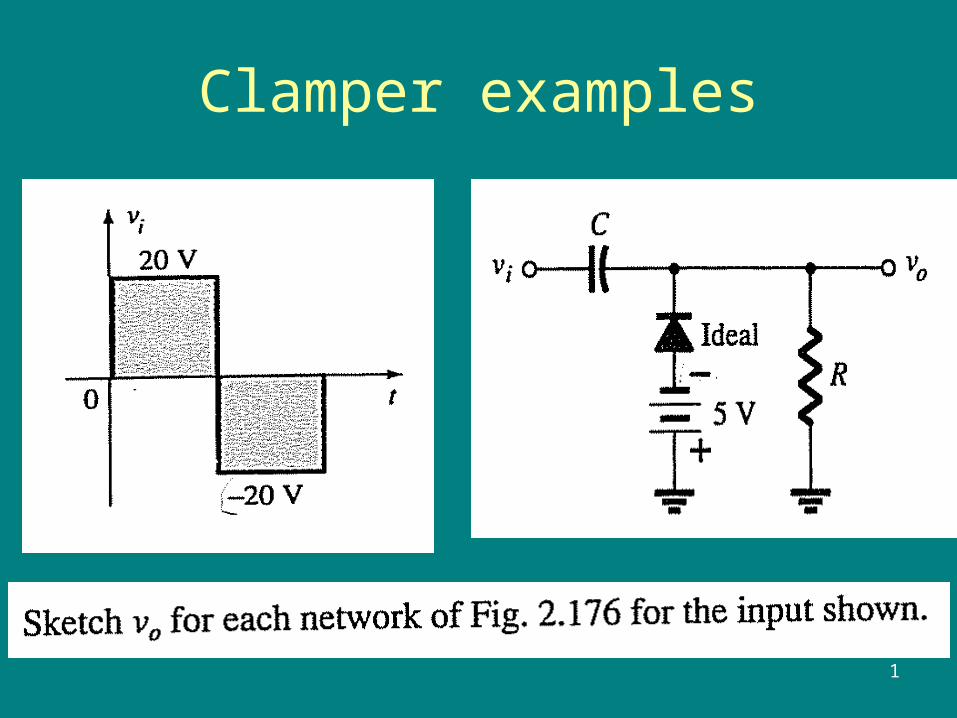
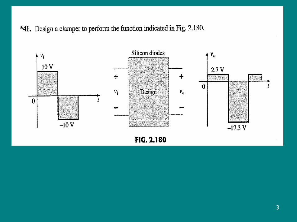
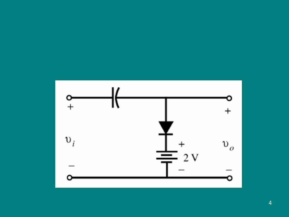
Clamper examples
1
2
3
4
5
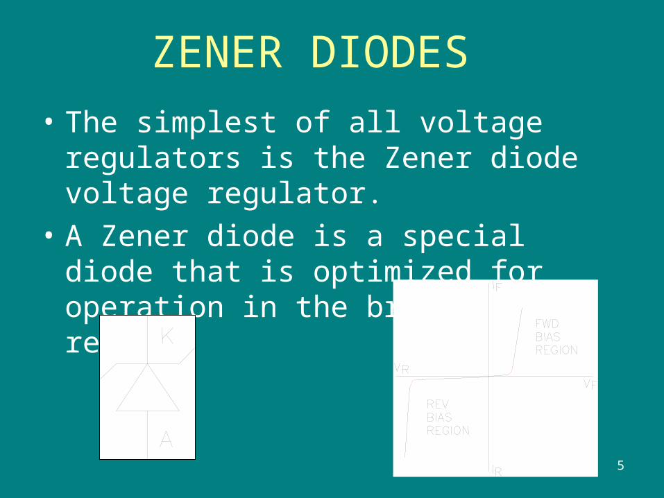
ZENER DIODES
• The simplest of all voltage regulators is the Zener diode voltage regulator.
• A Zener diode is a special diode that is optimized for operation in the breakdown region.
6
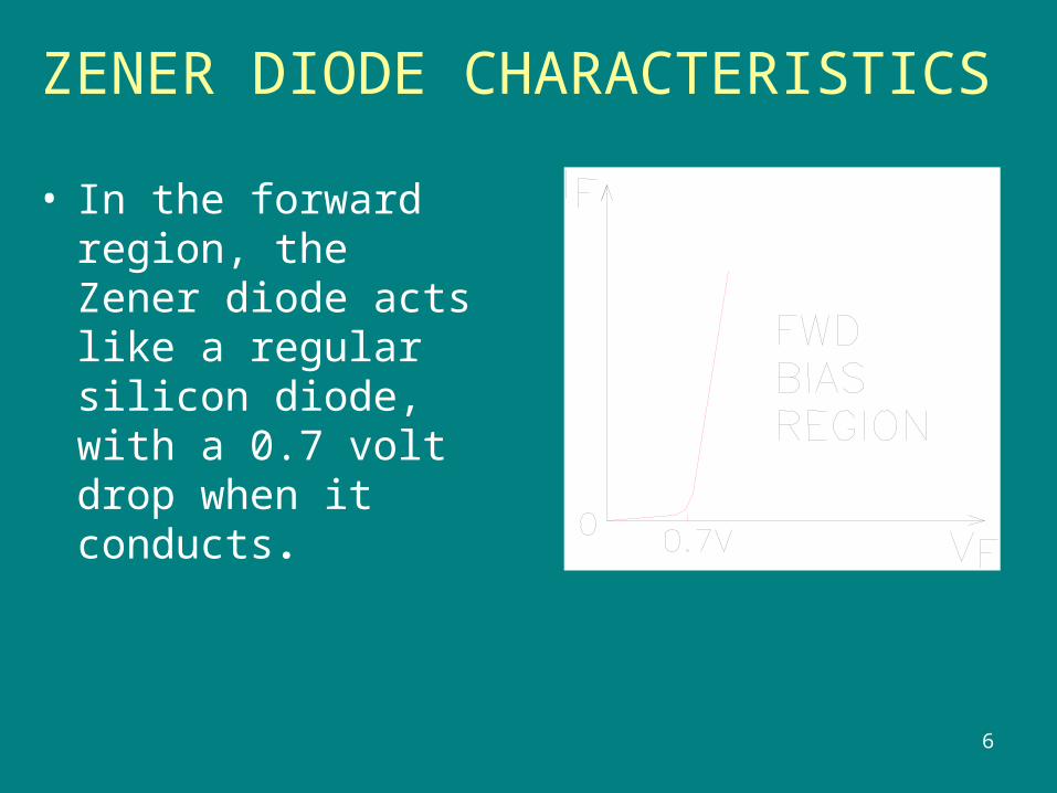
ZENER DIODE CHARACTERISTICS
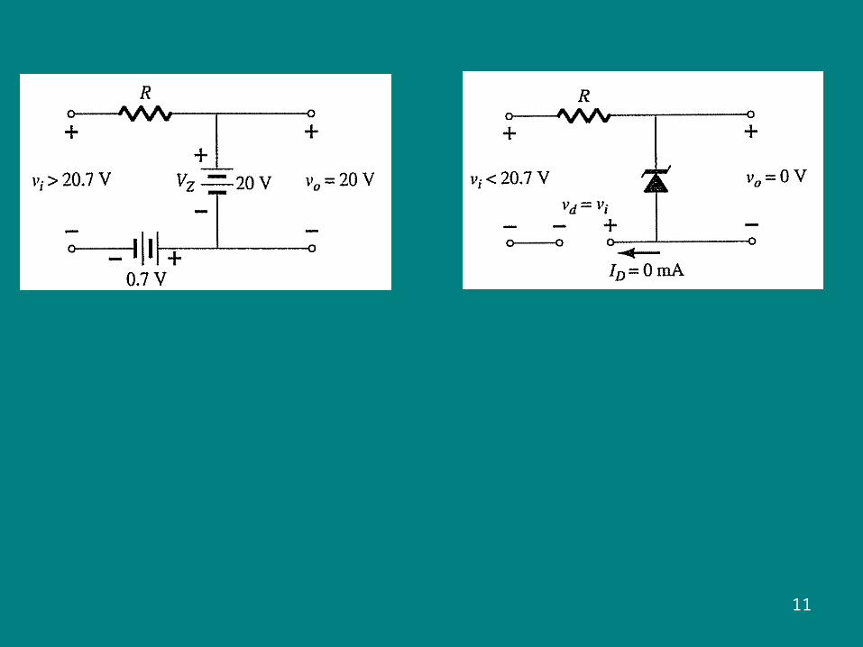
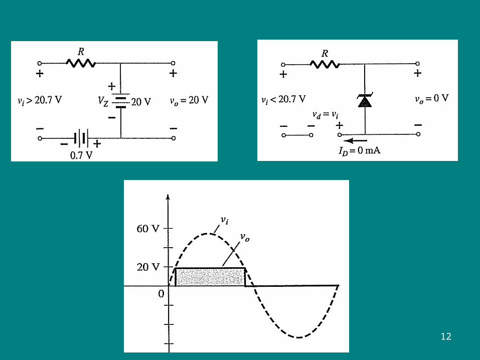
• In the forward region, the Zener diode acts like a regular silicon diode, with a 0.7 volt drop when it conducts.
7
ZENER DIODE CHARACTERISTICS
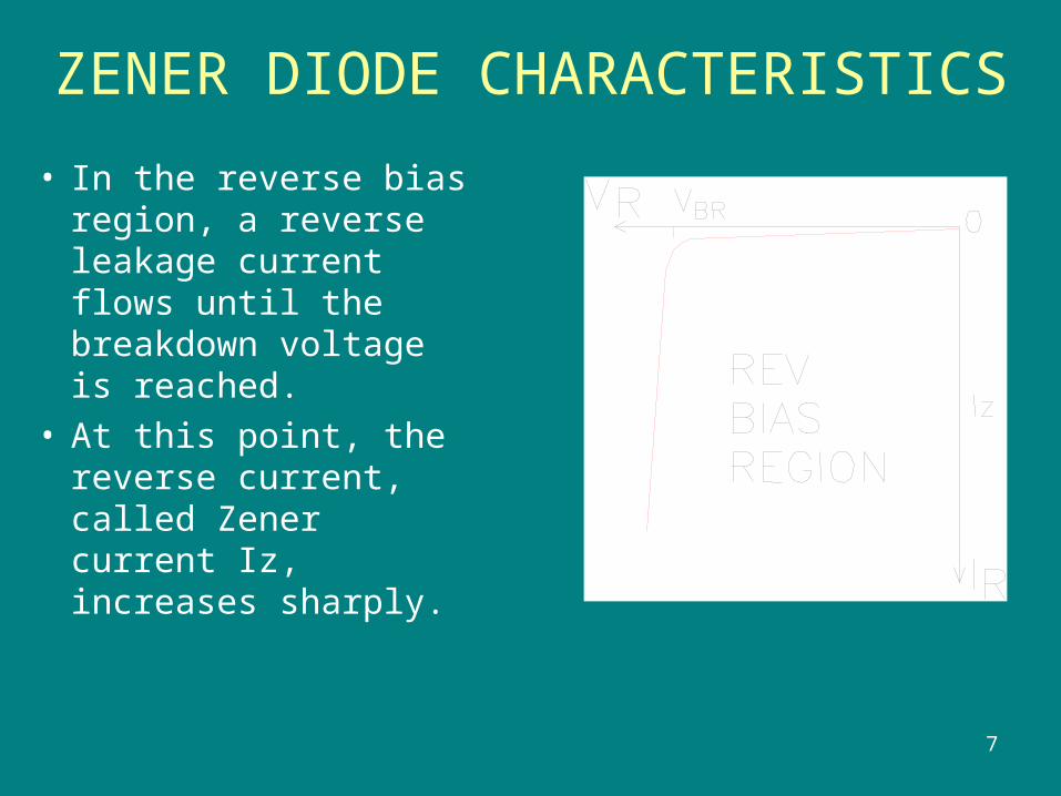
• In the reverse bias region, a reverse leakage current flows until the breakdown voltage is reached.
• At this point, the reverse current, called Zener current Iz, increases sharply.
8
ZENER DIODE CHARACTERISTICS
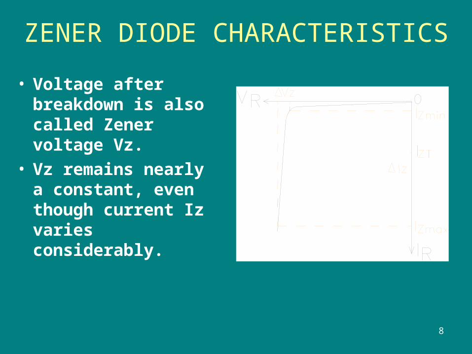
• Voltage after breakdown is also called Zener voltage Vz.
• Vz remains nearly a constant, even though current Iz varies considerably.
9
10
11
12
13
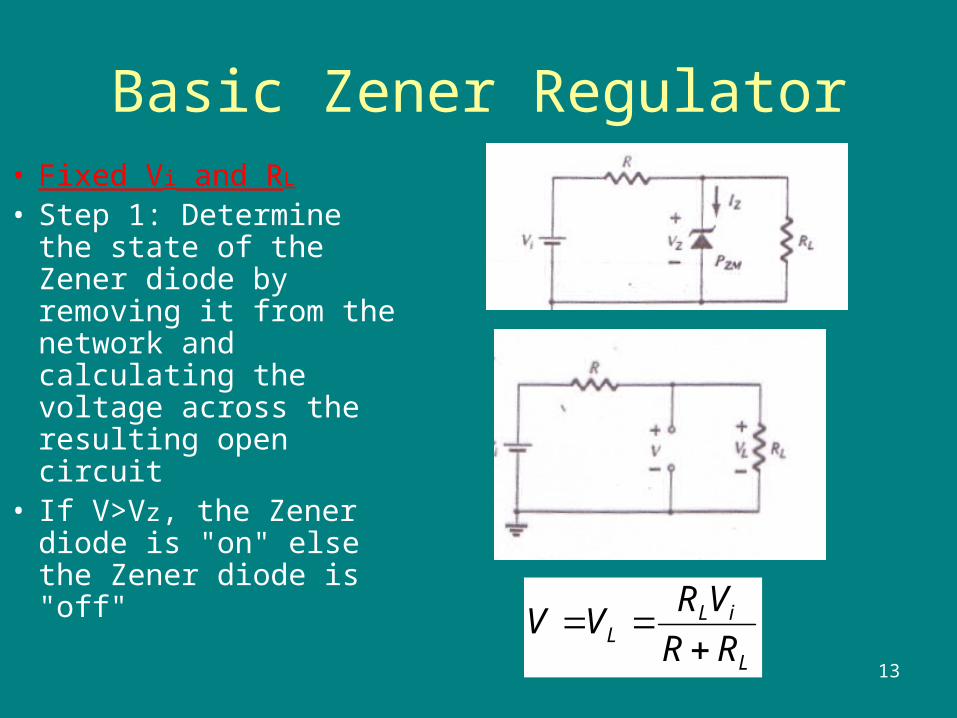
Basic Zener Regulator• Fixed Vi and RL
• Step 1: Determine the state of the Zener diode by removing it from the network and calculating the voltage across the resulting open circuit
• If V>Vz, the Zener diode is "on" else the Zener diode is "off"
L
iLL RR
VRVV
14
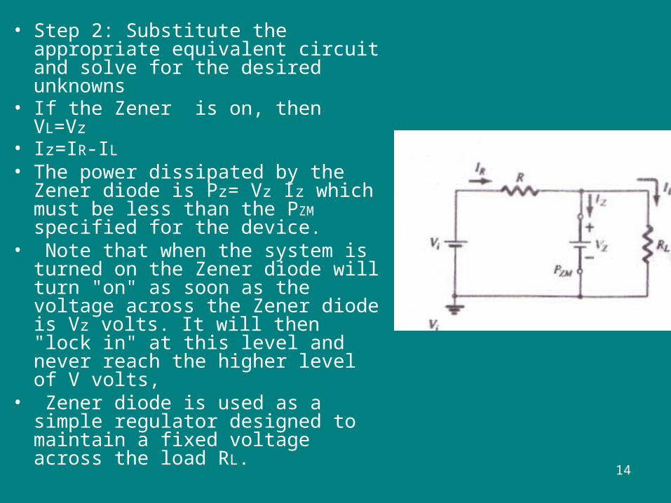
• Step 2: Substitute the appropriate equivalent circuit and solve for the desired unknowns
• If the Zener is on, then VL=Vz• Iz=IR-IL• The power dissipated by the
Zener diode is Pz= Vz Iz which must be less than the PZM specified for the device.
• Note that when the system is turned on the Zener diode will turn "on" as soon as the voltage across the Zener diode is Vz volts. It will then "lock in" at this level and never reach the higher level of V volts,
• Zener diode is used as a simple regulator designed to maintain a fixed voltage across the load RL.
15
Example
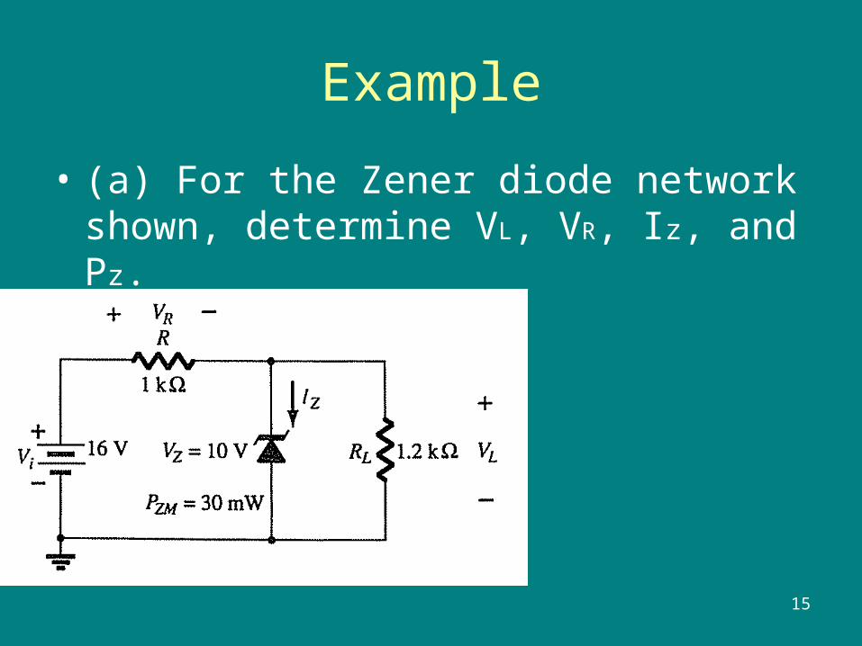
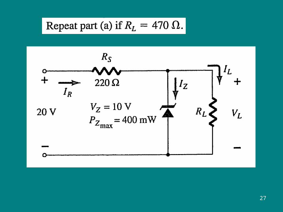
• (a) For the Zener diode network shown, determine VL, VR, Iz, and Pz.
16
Solution
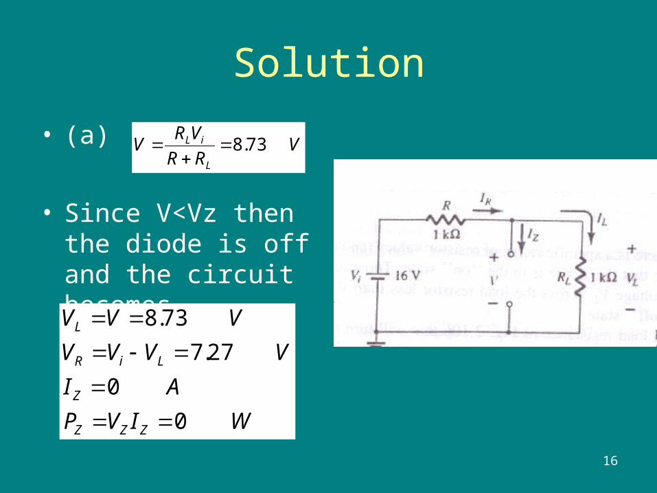
• (a)
• Since V<Vz then the diode is off and the circuit becomes
VRR
VRV
L
iL 73.8
WIVP
AI
VVVV
VVV
ZZZ
Z
LiR
L
0
0
27.7
73.8
17
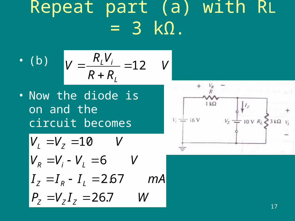
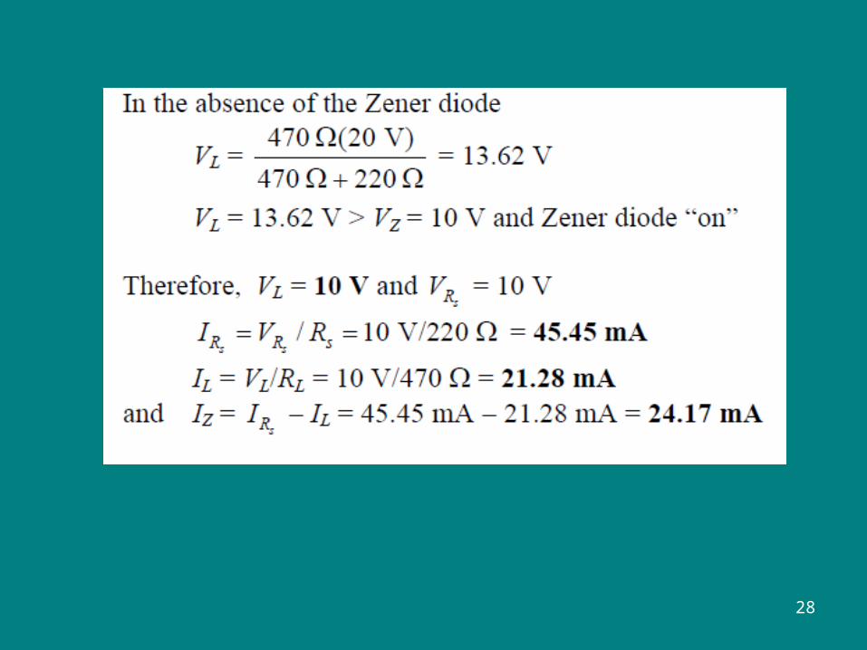
Repeat part (a) with RL = 3 kΩ.
• (b)
• Now the diode is on and the circuit becomes
VRR
VRV
L
iL 12
WIVP
mAIII
VVVV
VVV
ZZZ
LRZ
LiR
ZL
7.26
67.2
6
10
18
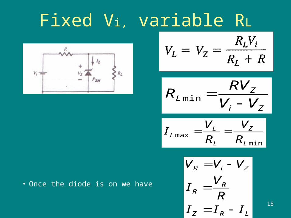
Fixed Vi, variable RL
• Once the diode is on we have
Zi
ZL VV
RVR
min
minmax
L
Z
L
LL R
V
R
VI
LRZ
RR
ZiR
IIIR
VI
VVV
19
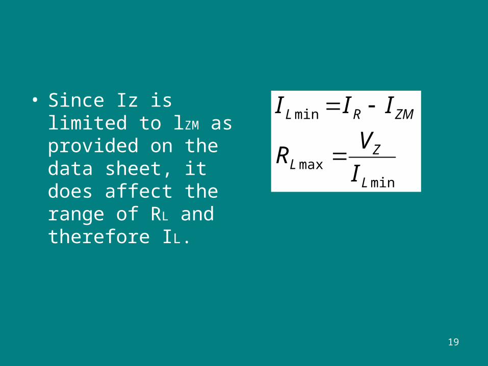
• Since Iz is limited to lZM as provided on the data sheet, it does affect the range of RL and therefore IL. min
max
min
L
ZL
ZMRL
I
VR
III
20
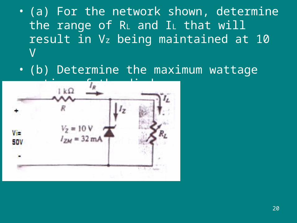
• (a) For the network shown, determine the range of RL and IL that will result in Vz being maintained at 10 V
• (b) Determine the maximum wattage rating of the diode
21
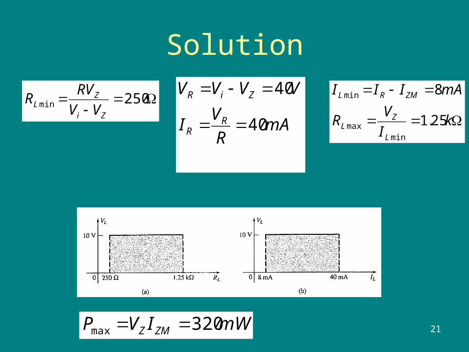
Solution
250minZi
ZL VV
RVR
mAR
VI
VVVV
RR
ZiR
40
40
kI
VR
mAIII
L
ZL
ZMRL
25.1
8
minmax
min
mWIVP ZMZ 320max
22
Fixed RL , variable Vi
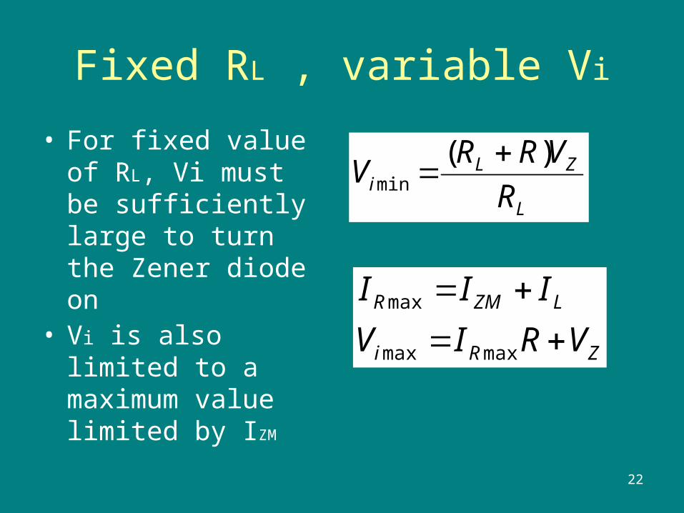
• For fixed value of RL, Vi must be sufficiently large to turn the Zener diode on
• Vi is also limited to a maximum value limited by IZM
L
ZLi R
VRRV
)(min
ZRi
LZMR
VRIV
III
maxmax
max
23
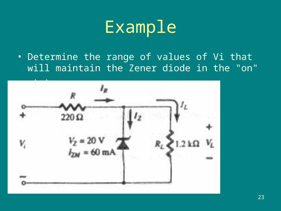
Example
• Determine the range of values of Vi that will maintain the
Zener diode in the "on" state
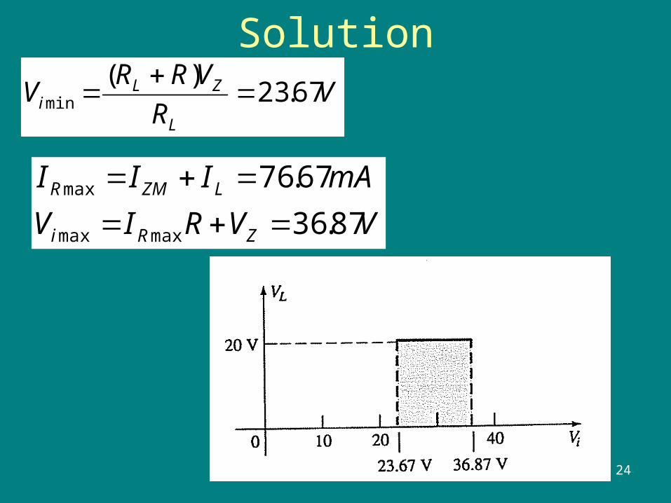
24
SolutionV
R
VRRV
L
ZLi 67.23
)(min
VVRIV
mAIII
ZRi
LZMR
87.36
67.76
maxmax
max
25
26
27
28
Voltage-Multiplier CircuitsVoltage-Multiplier Circuits
• Voltage Doubler
• Voltage Tripler
• Voltage Quadrupler
2929
Voltage multiplier circuits use a combination of diodes and capacitors to step up the output voltage of rectifier circuits.
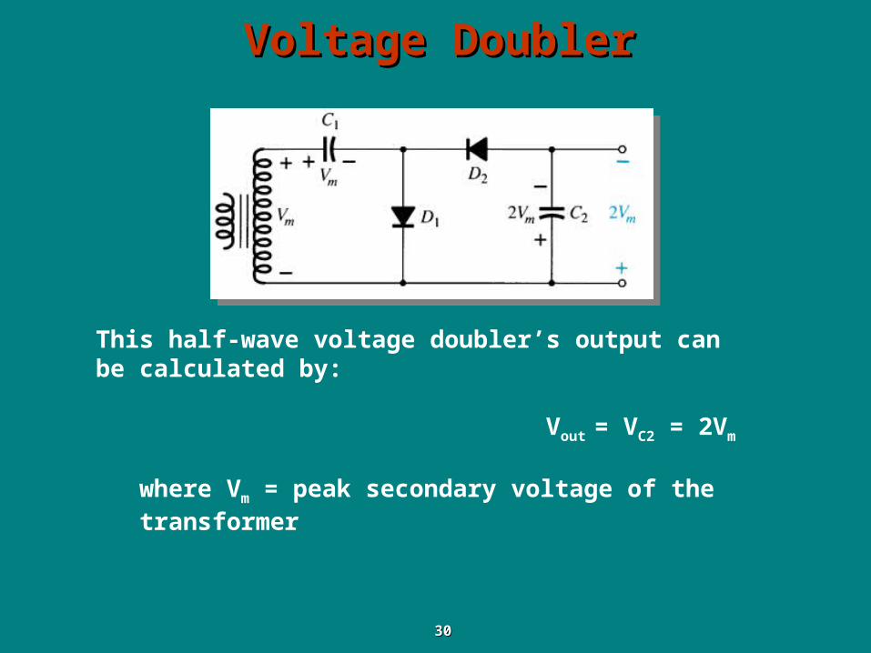
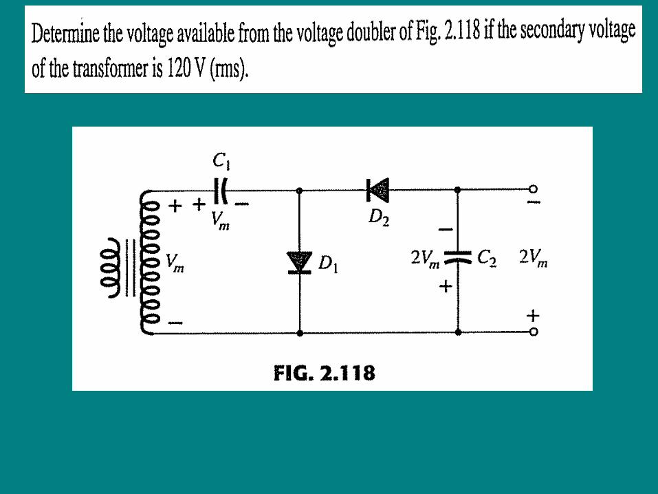
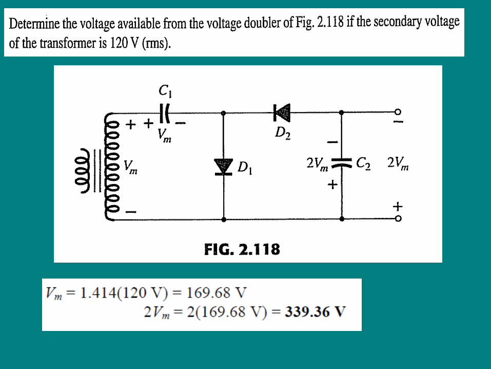
Voltage DoublerVoltage Doubler
3030
This half-wave voltage doubler’s output can be calculated by:
Vout = VC2 = 2Vm
where Vm = peak secondary voltage of the transformer
Voltage DoublerVoltage Doubler
3131
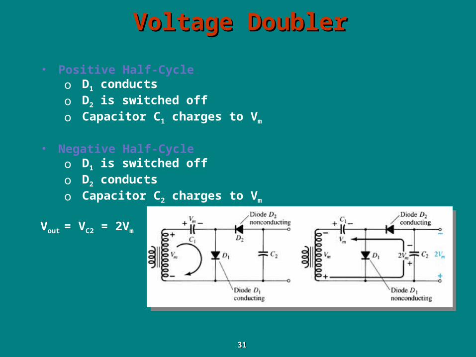
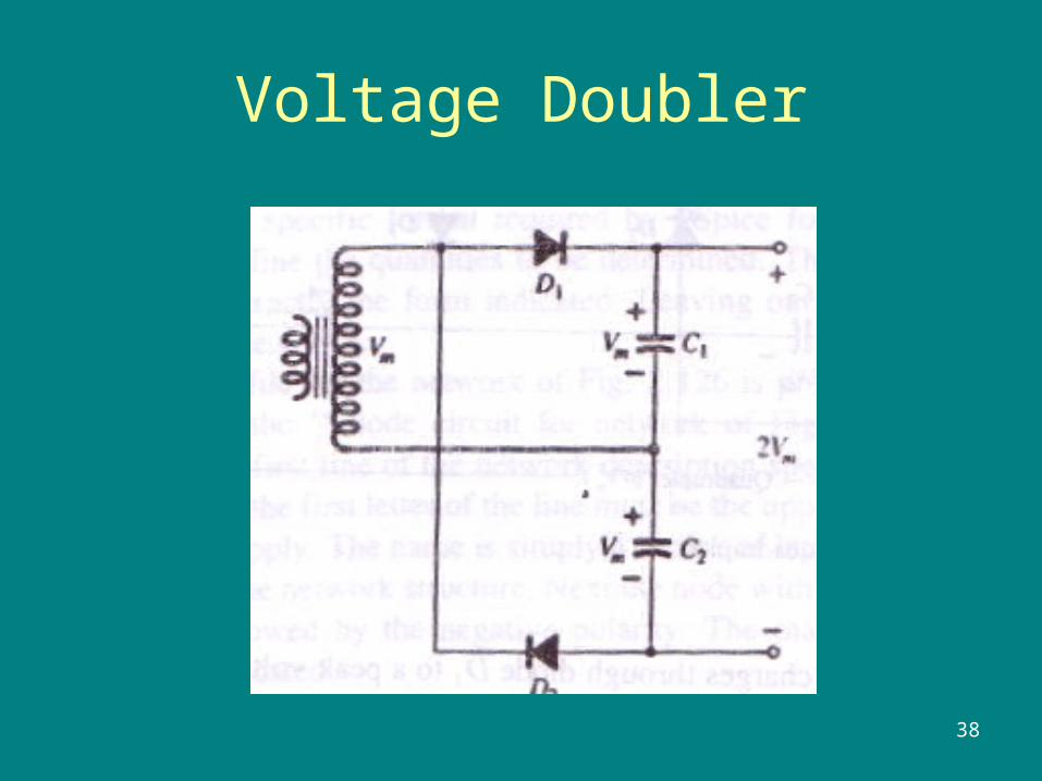
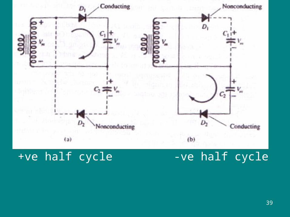
• Positive Half-Cycleo D1 conductso D2 is switched offo Capacitor C1 charges to Vm
• Negative Half-Cycleo D1 is switched offo D2 conductso Capacitor C2 charges to Vm
Vout = VC2 = 2Vm
Voltage Multipliers - Triplers
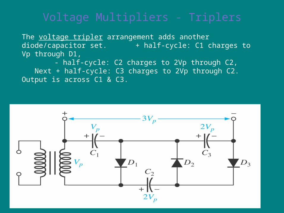
The voltage tripler arrangement adds another diode/capacitor set. + half-cycle: C1 charges to Vp through D1,
- half-cycle: C2 charges to 2Vp through C2, Next + half-cycle: C3 charges to 2Vp through C2. Output is across C1 & C3.
Voltage Multipliers - Quadruplers
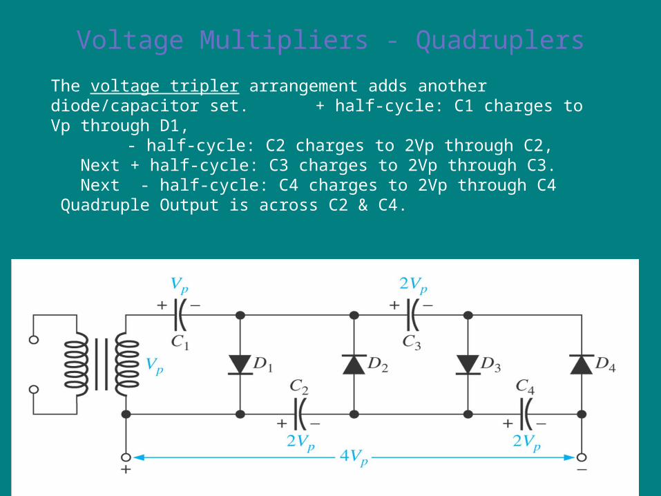
The voltage tripler arrangement adds another diode/capacitor set. + half-cycle: C1 charges to Vp through D1,
- half-cycle: C2 charges to 2Vp through C2, Next + half-cycle: C3 charges to 2Vp through C3. Next - half-cycle: C4 charges to 2Vp through C4 Quadruple Output is across C2 & C4.
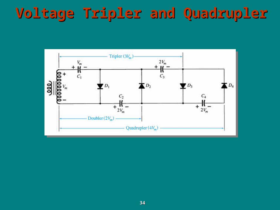
Voltage Tripler and QuadruplerVoltage Tripler and Quadrupler
3434
Practical ApplicationsPractical Applications
• Rectifier Circuits– Conversions of AC to DC for DC operated circuits– Battery Charging Circuits
• Simple Diode Circuits– clippers and clamper circuits in order to generate
different output voltage waveforms
• Zener Circuits– Overvoltage Protection– Setting Reference Voltages
3737
38
Voltage Doubler
39
+ve half cycle -ve half cycle