Embed Size (px)
Citation preview
Zener diodes
This worksheet and all related files are licensed under the Creative Commons Attribution License,version 1.0. To view a copy of this license, visit http://creativecommons.org/licenses/by/1.0/, or send aletter to Creative Commons, 559 Nathan Abbott Way, Stanford, California 94305, USA. The terms andconditions of this license allow for free copying, distribution, and/or modification of all licensed works bythe general public.
Resources and methods for learning about these subjects (list a few here, in preparation for yourresearch):
1
Questions
Question 1
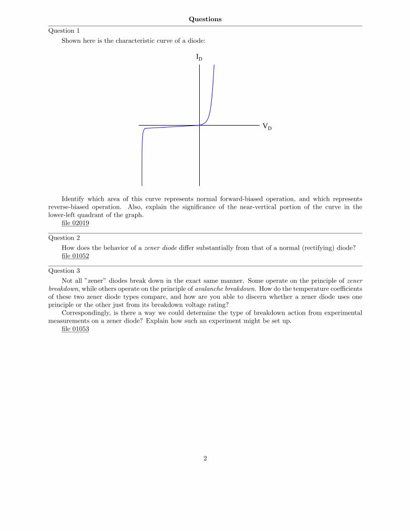
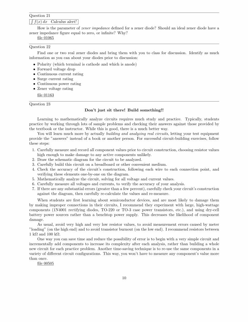
Shown here is the characteristic curve of a diode:
VD
ID
Identify which area of this curve represents normal forward-biased operation, and which representsreverse-biased operation. Also, explain the significance of the near-vertical portion of the curve in thelower-left quadrant of the graph.
file 02019
Question 2
How does the behavior of a zener diode differ substantially from that of a normal (rectifying) diode?file 01052
Question 3
Not all ”zener” diodes break down in the exact same manner. Some operate on the principle of zener
breakdown, while others operate on the principle of avalanche breakdown. How do the temperature coefficientsof these two zener diode types compare, and how are you able to discern whether a zener diode uses oneprinciple or the other just from its breakdown voltage rating?
Correspondingly, is there a way we could determine the type of breakdown action from experimentalmeasurements on a zener diode? Explain how such an experiment might be set up.
file 01053
2
Question 4
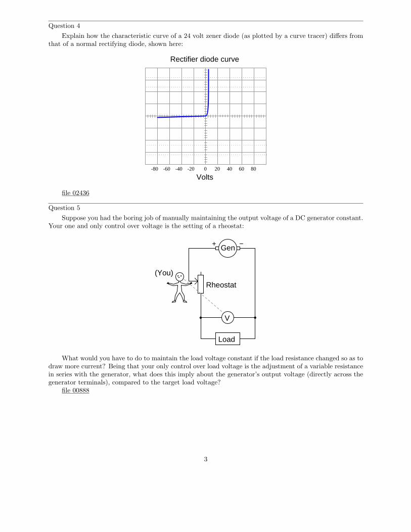
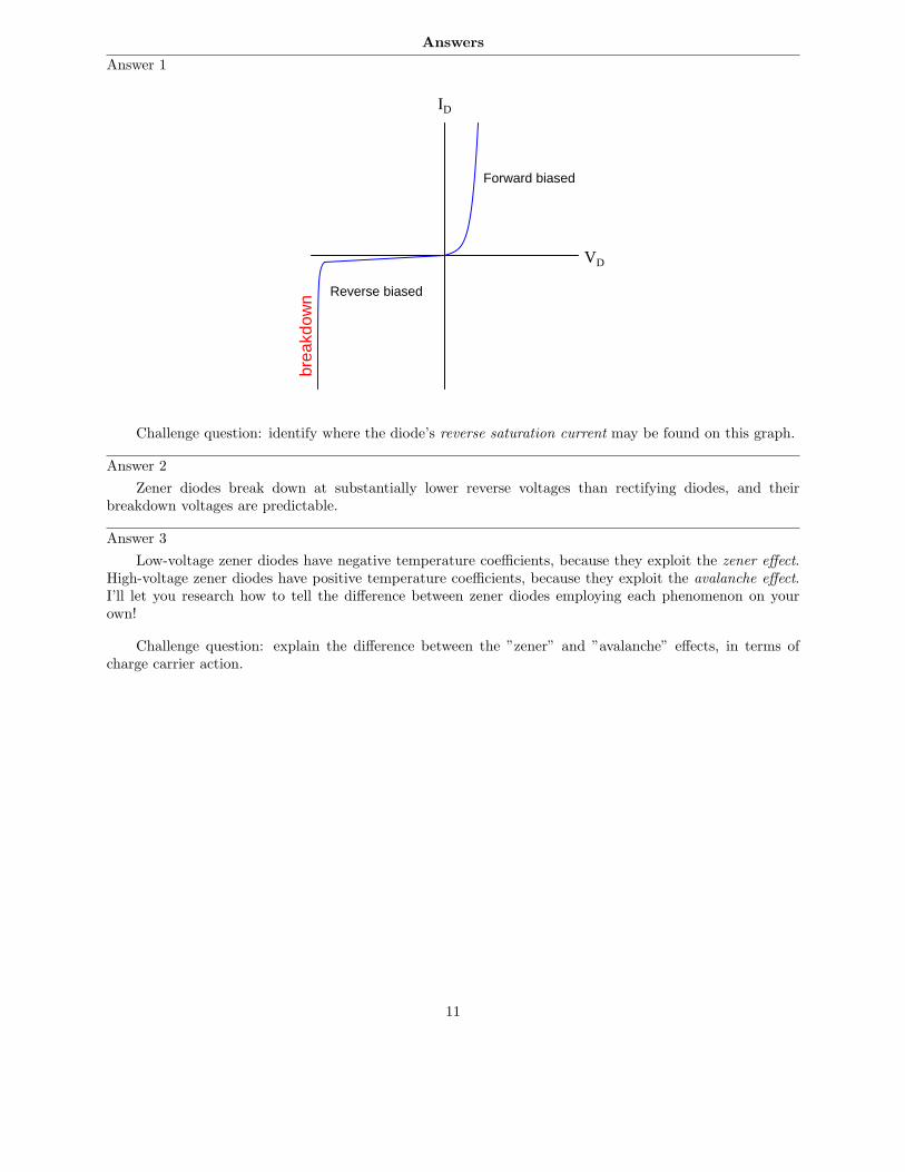
Explain how the characteristic curve of a 24 volt zener diode (as plotted by a curve tracer) differs fromthat of a normal rectifying diode, shown here:
Rectifier diode curve
0 20 40 60 80-20-40-60-80
Volts
file 02436
Question 5
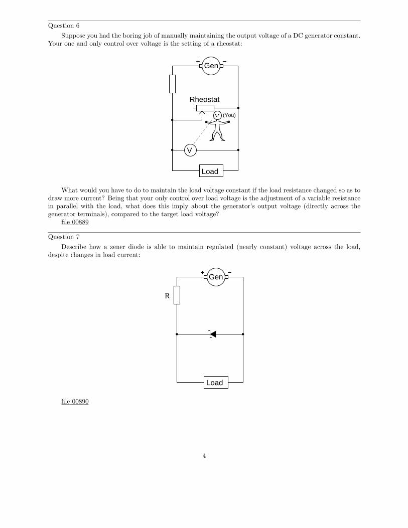
Suppose you had the boring job of manually maintaining the output voltage of a DC generator constant.Your one and only control over voltage is the setting of a rheostat:
Gen
Load
Rheostat
(You)
V
What would you have to do to maintain the load voltage constant if the load resistance changed so as todraw more current? Being that your only control over load voltage is the adjustment of a variable resistancein series with the generator, what does this imply about the generator’s output voltage (directly across thegenerator terminals), compared to the target load voltage?
file 00888
3
Question 6
Suppose you had the boring job of manually maintaining the output voltage of a DC generator constant.Your one and only control over voltage is the setting of a rheostat:
Gen
Load
Rheostat
(You)
V
What would you have to do to maintain the load voltage constant if the load resistance changed so as todraw more current? Being that your only control over load voltage is the adjustment of a variable resistancein parallel with the load, what does this imply about the generator’s output voltage (directly across thegenerator terminals), compared to the target load voltage?
file 00889
Question 7
Describe how a zener diode is able to maintain regulated (nearly constant) voltage across the load,despite changes in load current:
Gen
Load
R
file 00890
4
Question 8
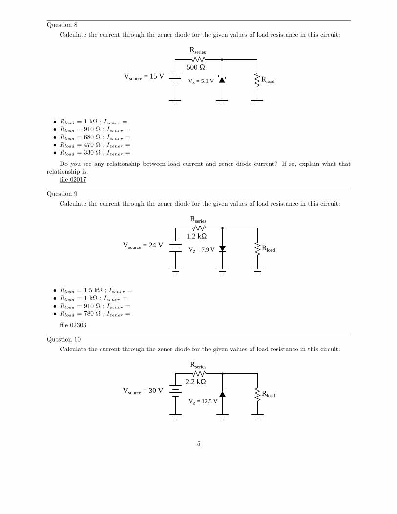
Calculate the current through the zener diode for the given values of load resistance in this circuit:
Rload
Rseries
VZ = 5.1 VVsource = 15 V
500 Ω
• Rload = 1 kΩ ; Izener =• Rload = 910 Ω ; Izener =• Rload = 680 Ω ; Izener =• Rload = 470 Ω ; Izener =• Rload = 330 Ω ; Izener =
Do you see any relationship between load current and zener diode current? If so, explain what thatrelationship is.
file 02017
Question 9
Calculate the current through the zener diode for the given values of load resistance in this circuit:
Rload
Rseries
Vsource = 24 V1.2 kΩ
VZ = 7.9 V
• Rload = 1.5 kΩ ; Izener =• Rload = 1 kΩ ; Izener =• Rload = 910 Ω ; Izener =• Rload = 780 Ω ; Izener =
file 02303
Question 10
Calculate the current through the zener diode for the given values of load resistance in this circuit:
Rload
Rseries
VZ = 12.5 V
2.2 kΩVsource = 30 V
5
• Rload = 2 kΩ ; Izener =• Rload = 3 kΩ ; Izener =• Rload = 4 kΩ ; Izener =• Rload = 5 kΩ ; Izener =
file 02317
Question 11
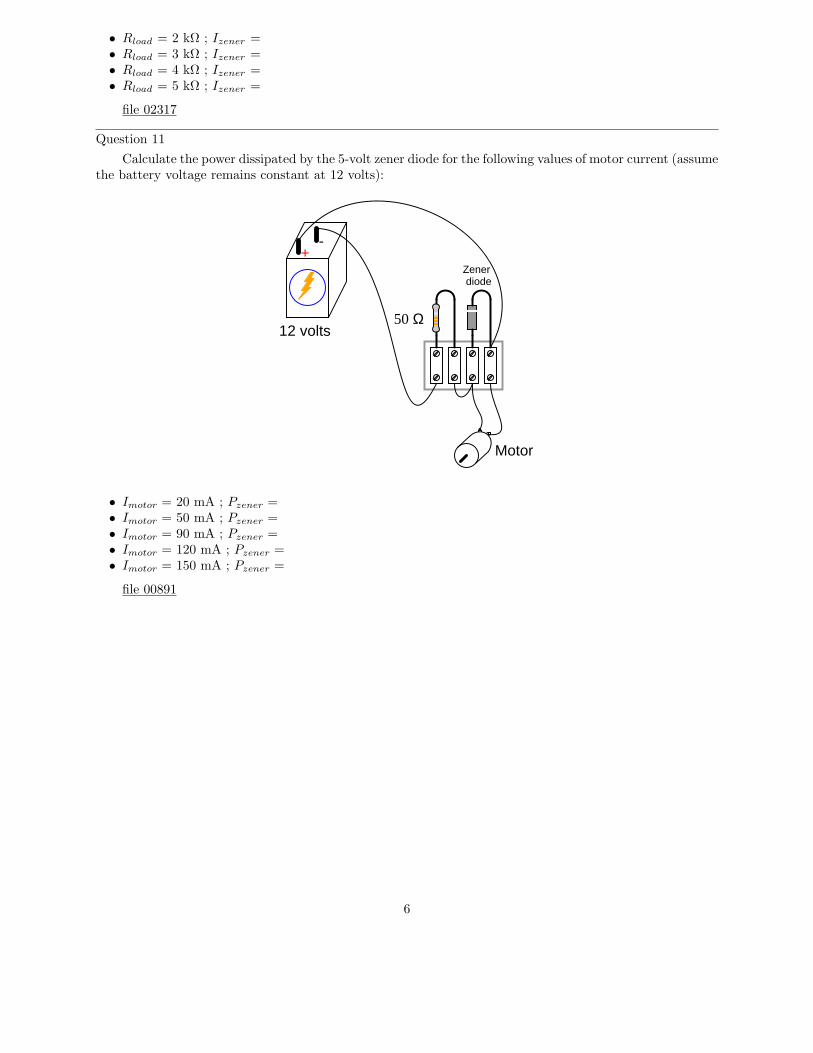
Calculate the power dissipated by the 5-volt zener diode for the following values of motor current (assumethe battery voltage remains constant at 12 volts):
+-
12 volts
Motor
Zenerdiode
50 Ω
• Imotor = 20 mA ; Pzener =• Imotor = 50 mA ; Pzener =• Imotor = 90 mA ; Pzener =• Imotor = 120 mA ; Pzener =• Imotor = 150 mA ; Pzener =
file 00891
6
Question 12
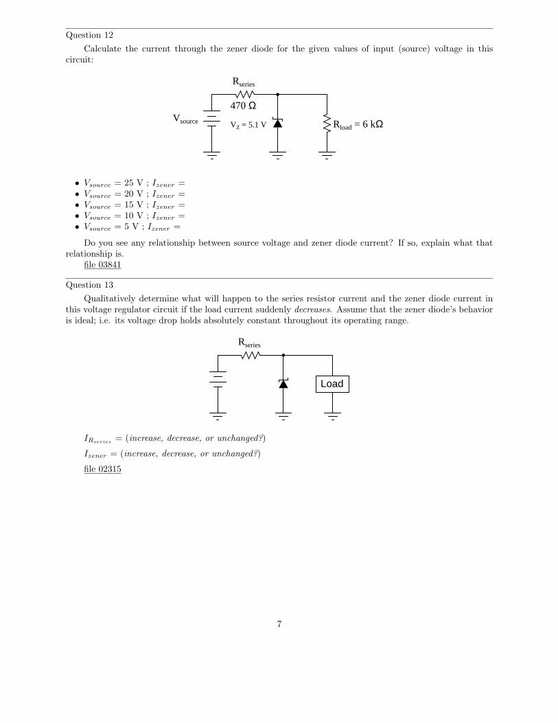
Calculate the current through the zener diode for the given values of input (source) voltage in thiscircuit:
Rseries
VZ = 5.1 VVsource
470 Ω
Rload = 6 kΩ
• Vsource = 25 V ; Izener =• Vsource = 20 V ; Izener =• Vsource = 15 V ; Izener =• Vsource = 10 V ; Izener =• Vsource = 5 V ; Izener =
Do you see any relationship between source voltage and zener diode current? If so, explain what thatrelationship is.
file 03841
Question 13
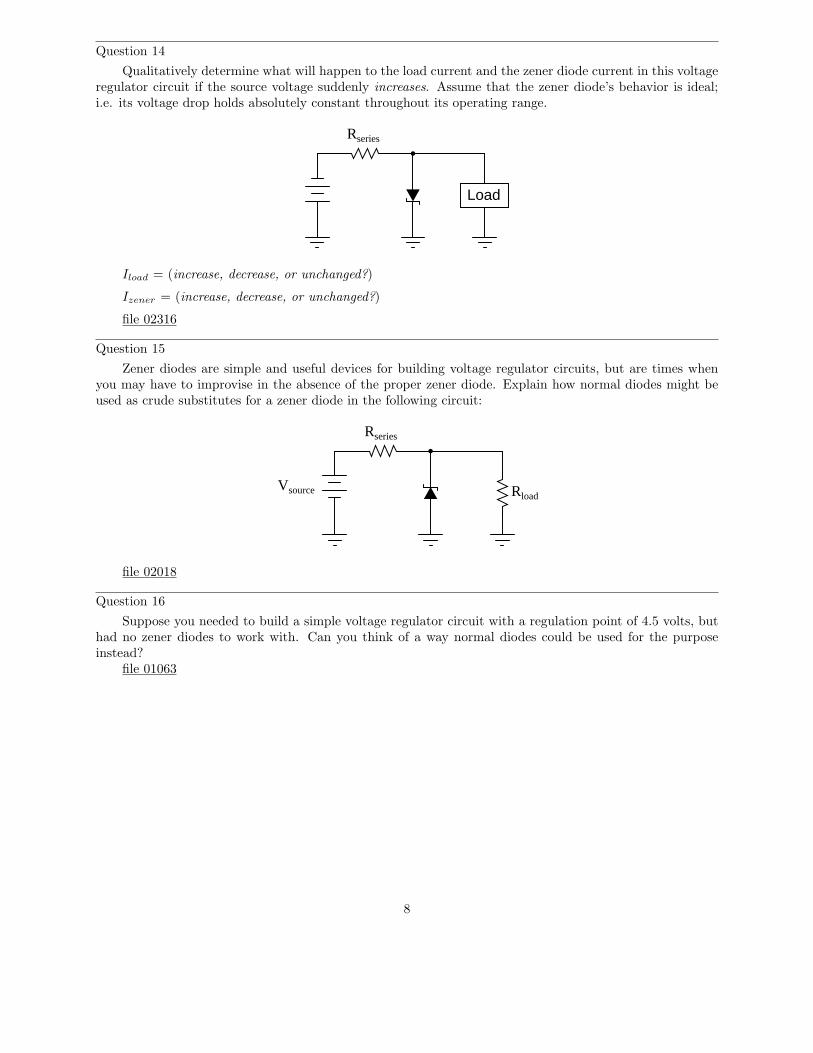
Qualitatively determine what will happen to the series resistor current and the zener diode current inthis voltage regulator circuit if the load current suddenly decreases. Assume that the zener diode’s behavioris ideal; i.e. its voltage drop holds absolutely constant throughout its operating range.
Rseries
Load
IRseries= (increase, decrease, or unchanged?)
Izener = (increase, decrease, or unchanged?)
file 02315
7
Question 14
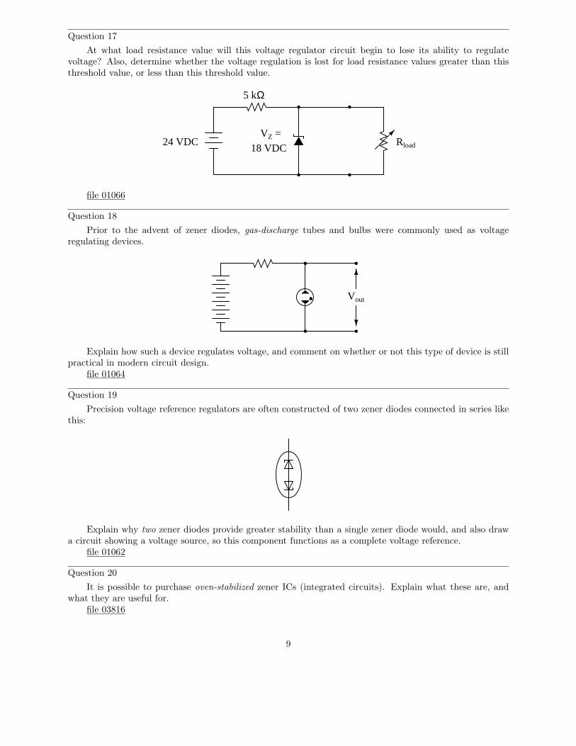
Qualitatively determine what will happen to the load current and the zener diode current in this voltageregulator circuit if the source voltage suddenly increases. Assume that the zener diode’s behavior is ideal;i.e. its voltage drop holds absolutely constant throughout its operating range.
Rseries
Load
Iload = (increase, decrease, or unchanged?)
Izener = (increase, decrease, or unchanged?)
file 02316
Question 15
Zener diodes are simple and useful devices for building voltage regulator circuits, but are times whenyou may have to improvise in the absence of the proper zener diode. Explain how normal diodes might beused as crude substitutes for a zener diode in the following circuit:
Rload
Rseries
Vsource
file 02018
Question 16
Suppose you needed to build a simple voltage regulator circuit with a regulation point of 4.5 volts, buthad no zener diodes to work with. Can you think of a way normal diodes could be used for the purposeinstead?
file 01063
8
Question 17
At what load resistance value will this voltage regulator circuit begin to lose its ability to regulatevoltage? Also, determine whether the voltage regulation is lost for load resistance values greater than thisthreshold value, or less than this threshold value.
24 VDC18 VDC
VZ =
5 kΩ
Rload
file 01066
Question 18
Prior to the advent of zener diodes, gas-discharge tubes and bulbs were commonly used as voltageregulating devices.
Vout
Explain how such a device regulates voltage, and comment on whether or not this type of device is stillpractical in modern circuit design.
file 01064
Question 19
Precision voltage reference regulators are often constructed of two zener diodes connected in series likethis:
Explain why two zener diodes provide greater stability than a single zener diode would, and also drawa circuit showing a voltage source, so this component functions as a complete voltage reference.
file 01062
Question 20
It is possible to purchase oven-stabilized zener ICs (integrated circuits). Explain what these are, andwhat they are useful for.
file 03816
9
Question 21∫
f(x) dx Calculus alert!
How is the parameter of zener impedance defined for a zener diode? Should an ideal zener diode have azener impedance figure equal to zero, or infinite? Why?
file 01065
Question 22
Find one or two real zener diodes and bring them with you to class for discussion. Identify as muchinformation as you can about your diodes prior to discussion:
• Polarity (which terminal is cathode and which is anode)• Forward voltage drop• Continuous current rating• Surge current rating• Continuous power rating• Zener voltage rating
file 01163
Question 23
Don’t just sit there! Build something!!
Learning to mathematically analyze circuits requires much study and practice. Typically, studentspractice by working through lots of sample problems and checking their answers against those provided bythe textbook or the instructor. While this is good, there is a much better way.
You will learn much more by actually building and analyzing real circuits, letting your test equipmentprovide the ”answers” instead of a book or another person. For successful circuit-building exercises, followthese steps:
1. Carefully measure and record all component values prior to circuit construction, choosing resistor valueshigh enough to make damage to any active components unlikely.
2. Draw the schematic diagram for the circuit to be analyzed.3. Carefully build this circuit on a breadboard or other convenient medium.4. Check the accuracy of the circuit’s construction, following each wire to each connection point, and
verifying these elements one-by-one on the diagram.5. Mathematically analyze the circuit, solving for all voltage and current values.6. Carefully measure all voltages and currents, to verify the accuracy of your analysis.7. If there are any substantial errors (greater than a few percent), carefully check your circuit’s construction
against the diagram, then carefully re-calculate the values and re-measure.
When students are first learning about semiconductor devices, and are most likely to damage themby making improper connections in their circuits, I recommend they experiment with large, high-wattagecomponents (1N4001 rectifying diodes, TO-220 or TO-3 case power transistors, etc.), and using dry-cellbattery power sources rather than a benchtop power supply. This decreases the likelihood of componentdamage.
As usual, avoid very high and very low resistor values, to avoid measurement errors caused by meter”loading” (on the high end) and to avoid transistor burnout (on the low end). I recommend resistors between1 kΩ and 100 kΩ.
One way you can save time and reduce the possibility of error is to begin with a very simple circuit andincrementally add components to increase its complexity after each analysis, rather than building a wholenew circuit for each practice problem. Another time-saving technique is to re-use the same components in avariety of different circuit configurations. This way, you won’t have to measure any component’s value morethan once.
file 00505
10
Answers
Answer 1
VD
ID
Forward biased
Reverse biasedbr
eakd
own
Challenge question: identify where the diode’s reverse saturation current may be found on this graph.
Answer 2
Zener diodes break down at substantially lower reverse voltages than rectifying diodes, and theirbreakdown voltages are predictable.
Answer 3
Low-voltage zener diodes have negative temperature coefficients, because they exploit the zener effect.High-voltage zener diodes have positive temperature coefficients, because they exploit the avalanche effect.I’ll let you research how to tell the difference between zener diodes employing each phenomenon on yourown!
Challenge question: explain the difference between the ”zener” and ”avalanche” effects, in terms ofcharge carrier action.
11
Answer 4
0 20 40 60 80-20-40-60-80
Volts
24 volt zener diode curve
Answer 5
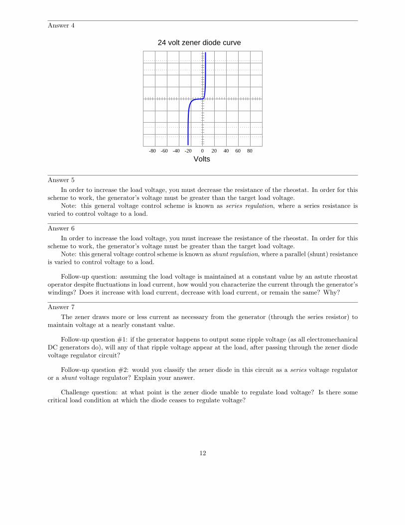
In order to increase the load voltage, you must decrease the resistance of the rheostat. In order for thisscheme to work, the generator’s voltage must be greater than the target load voltage.
Note: this general voltage control scheme is known as series regulation, where a series resistance isvaried to control voltage to a load.
Answer 6
In order to increase the load voltage, you must increase the resistance of the rheostat. In order for thisscheme to work, the generator’s voltage must be greater than the target load voltage.
Note: this general voltage control scheme is known as shunt regulation, where a parallel (shunt) resistanceis varied to control voltage to a load.
Follow-up question: assuming the load voltage is maintained at a constant value by an astute rheostatoperator despite fluctuations in load current, how would you characterize the current through the generator’swindings? Does it increase with load current, decrease with load current, or remain the same? Why?
Answer 7
The zener draws more or less current as necessary from the generator (through the series resistor) tomaintain voltage at a nearly constant value.
Follow-up question #1: if the generator happens to output some ripple voltage (as all electromechanicalDC generators do), will any of that ripple voltage appear at the load, after passing through the zener diodevoltage regulator circuit?
Follow-up question #2: would you classify the zener diode in this circuit as a series voltage regulatoror a shunt voltage regulator? Explain your answer.
Challenge question: at what point is the zener diode unable to regulate load voltage? Is there somecritical load condition at which the diode ceases to regulate voltage?
12
Answer 8
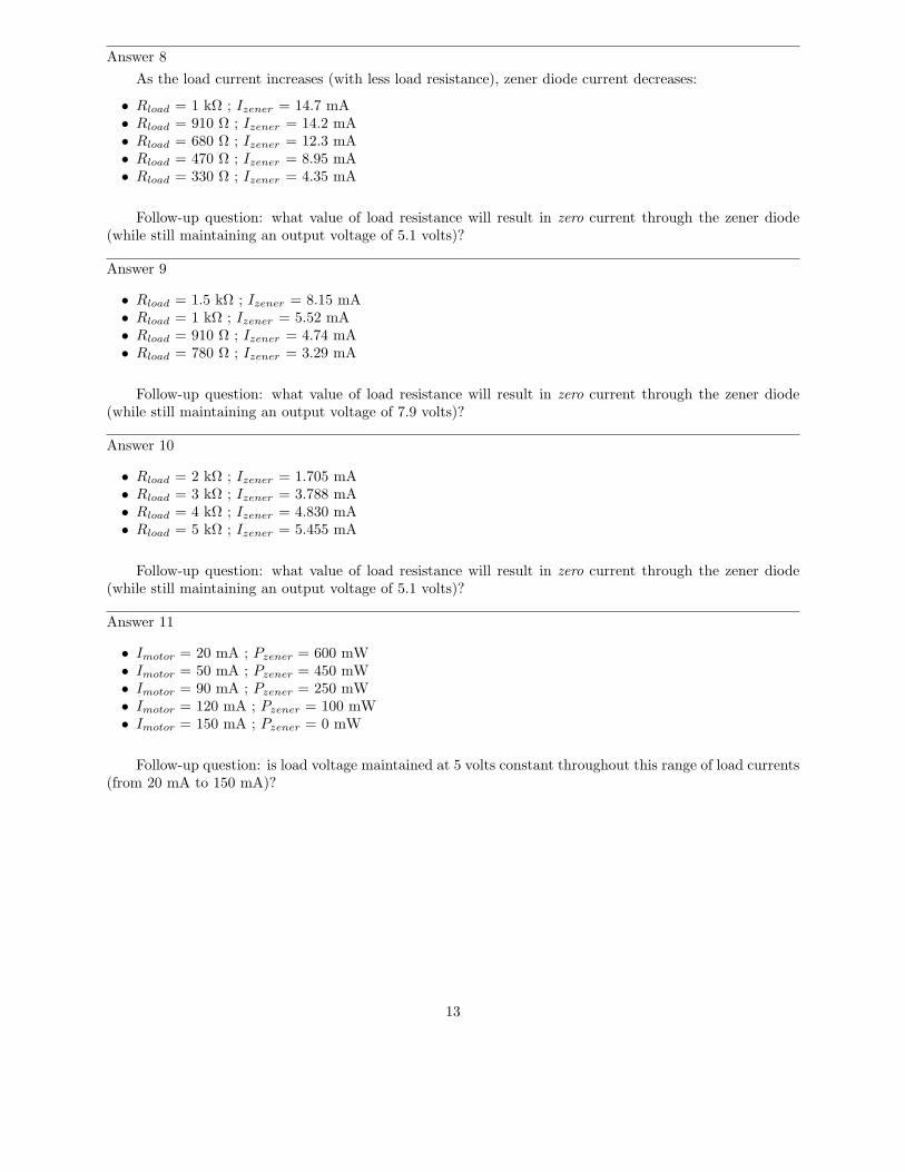
As the load current increases (with less load resistance), zener diode current decreases:
• Rload = 1 kΩ ; Izener = 14.7 mA• Rload = 910 Ω ; Izener = 14.2 mA• Rload = 680 Ω ; Izener = 12.3 mA• Rload = 470 Ω ; Izener = 8.95 mA• Rload = 330 Ω ; Izener = 4.35 mA
Follow-up question: what value of load resistance will result in zero current through the zener diode(while still maintaining an output voltage of 5.1 volts)?
Answer 9
• Rload = 1.5 kΩ ; Izener = 8.15 mA• Rload = 1 kΩ ; Izener = 5.52 mA• Rload = 910 Ω ; Izener = 4.74 mA• Rload = 780 Ω ; Izener = 3.29 mA
Follow-up question: what value of load resistance will result in zero current through the zener diode(while still maintaining an output voltage of 7.9 volts)?
Answer 10
• Rload = 2 kΩ ; Izener = 1.705 mA• Rload = 3 kΩ ; Izener = 3.788 mA• Rload = 4 kΩ ; Izener = 4.830 mA• Rload = 5 kΩ ; Izener = 5.455 mA
Follow-up question: what value of load resistance will result in zero current through the zener diode(while still maintaining an output voltage of 5.1 volts)?
Answer 11
• Imotor = 20 mA ; Pzener = 600 mW• Imotor = 50 mA ; Pzener = 450 mW• Imotor = 90 mA ; Pzener = 250 mW• Imotor = 120 mA ; Pzener = 100 mW• Imotor = 150 mA ; Pzener = 0 mW
Follow-up question: is load voltage maintained at 5 volts constant throughout this range of load currents(from 20 mA to 150 mA)?
13
Answer 12
As the source voltage decreases, zener diode current also decreases:
• Vsource = 25 V ; Izener = 41.49 mA• Vsource = 20 V ; Izener = 30.85 mA• Vsource = 15 V ; Izener = 20.21 mA• Vsource = 10 V ; Izener = 9.58 mA• Vsource = 5 V ; Izener = 0 mA
Follow-up question: what value of source voltage input will result in zero current through the zenerdiode (while still maintaining an output voltage of 5.1 volts)?
Answer 13
If the load current decreases, Izener will increase and IRserieswill remain unchanged.
Challenge question: what do you think will happen with a real zener diode, where its voltage drop doeschange slightly with changes in current?
Answer 14
If the source voltage increases, Izener will increase and Iload will remain unchanged.
Challenge question: what do you think will happen with a real zener diode, where its voltage drop doeschange slightly with changes in current?
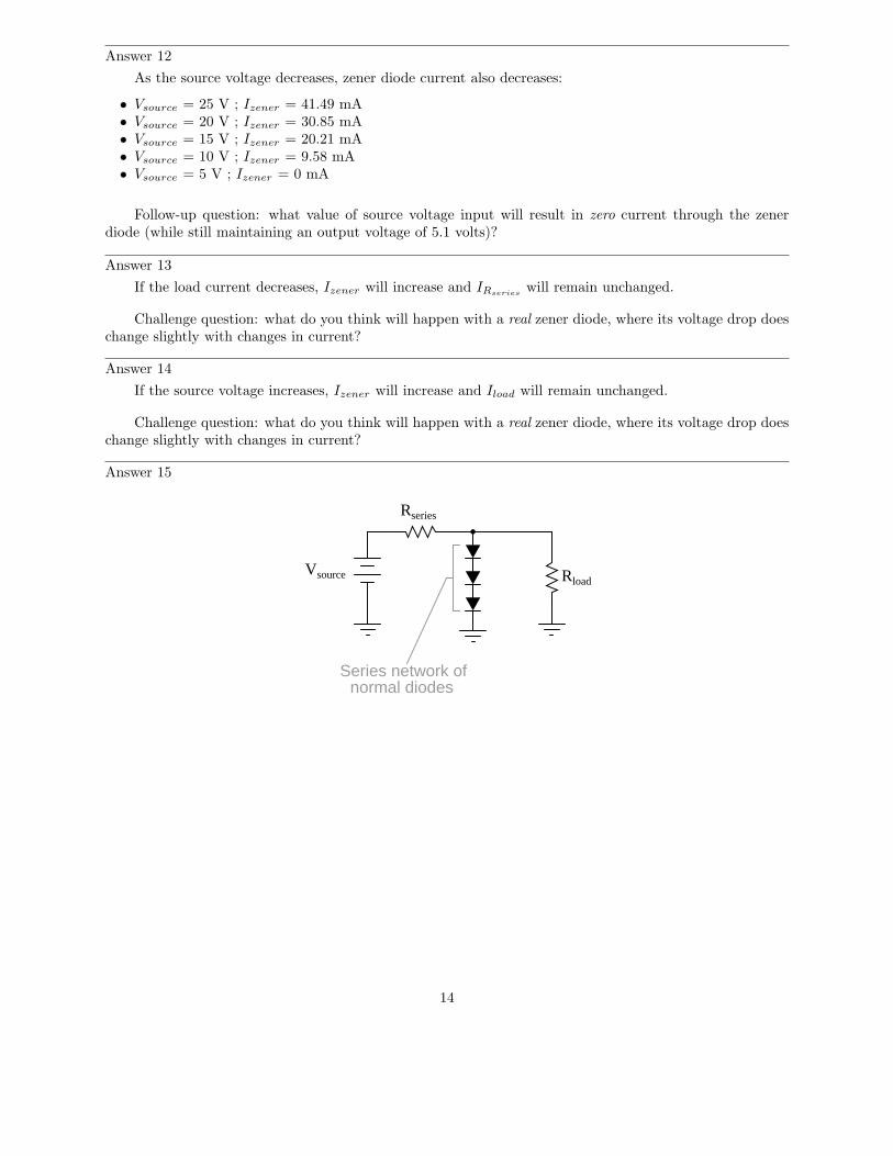
Answer 15
Rload
Rseries
Vsource
Series network ofnormal diodes
14
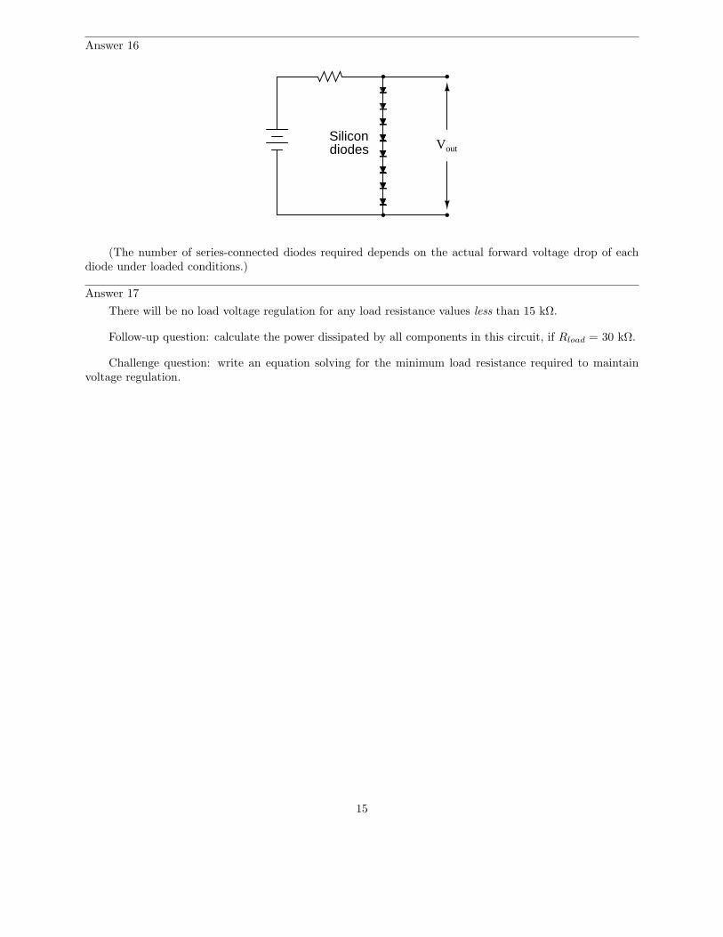
Answer 16
VoutSilicondiodes
(The number of series-connected diodes required depends on the actual forward voltage drop of eachdiode under loaded conditions.)
Answer 17
There will be no load voltage regulation for any load resistance values less than 15 kΩ.
Follow-up question: calculate the power dissipated by all components in this circuit, if Rload = 30 kΩ.
Challenge question: write an equation solving for the minimum load resistance required to maintainvoltage regulation.
15
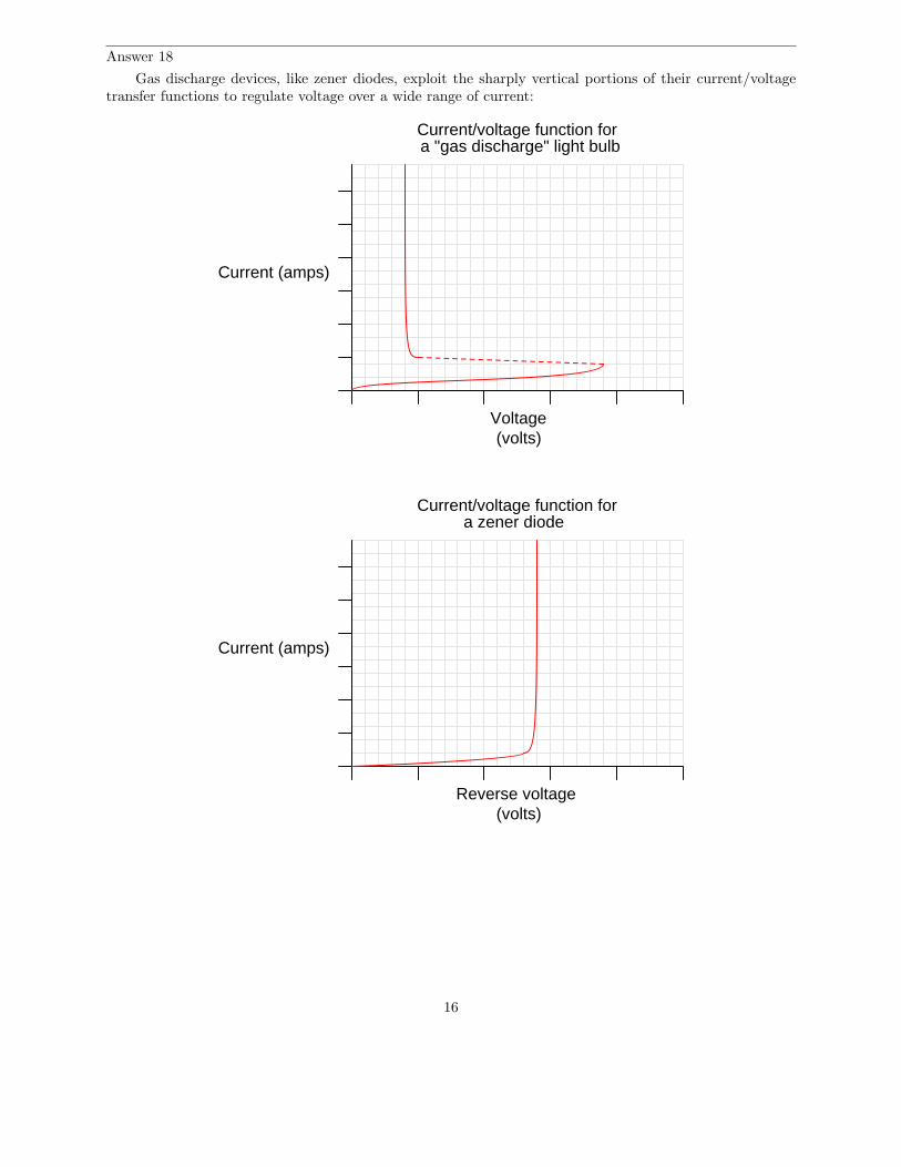
Answer 18
Gas discharge devices, like zener diodes, exploit the sharply vertical portions of their current/voltagetransfer functions to regulate voltage over a wide range of current:
Voltage(volts)
Current (amps)
a "gas discharge" light bulbCurrent/voltage function for
(volts)
Current (amps)
Current/voltage function for
Reverse voltage
a zener diode
16
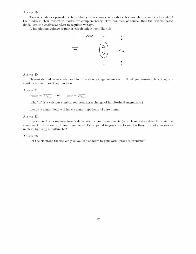
Answer 19
Two zener diodes provide better stability than a single zener diode because the thermal coefficients ofthe diodes in their respective modes are complementary. This assumes, of course, that the reverse-biaseddiode uses the avalanche effect to regulate voltage.
A functioning voltage regulator circuit might look like this:
Vout
Answer 20
Oven-stabilized zeners are used for precision voltage references. I’ll let you research how they areconstructed and how they function.
Answer 21
Zzener = ∆Ediode
∆Idiode
or Zzener = dEdiode
dIdiode
(The ”d” is a calculus symbol, representing a change of infinitesimal magnitude.)
Ideally, a zener diode will have a zener impedance of zero ohms.
Answer 22
If possible, find a manufacturer’s datasheet for your components (or at least a datasheet for a similarcomponent) to discuss with your classmates. Be prepared to prove the forward voltage drop of your diodesin class, by using a multimeter!
Answer 23
Let the electrons themselves give you the answers to your own ”practice problems”!
17
Notes
Notes 1
Ask your students to identify the region of the curve described by Shockley’s diode equation. Theexponential form of that equation really only models one definite portion of the curve!
Notes 2
Ask students what zener diodes would likely be used for. Why would we need or desire a device with astable breakdown voltage?
Notes 3
Regular ”rectifying” diodes also have temperature coefficients. Ask your students to identify whether thetemperature coefficient for a rectifying diode is typically positive or negative, and what this actually means.It is very easy to experimentally verify this, so you may want to ask your students to demonstrate how todetermine the sign of a rectifying diode’s temperature coefficient as a prelude to reviewing the experimentalportion of the original question.
Ask your students to identify the typical voltage values associated with both types of breakdown effect.This will quickly reveal which students did their research for this question, as opposed to those who merelyread the answer given here!
Notes 4
The purpose of this question is to cause students to think about what a characteristic curve means, inthe context of diode comparisons. The breakdown voltage of a zener diode is typically so low compared tothat of a normal rectifying diode that this region may be easily shown on the curve tracer screen.
Notes 5
The direction of rheostat adjustment should be obvious, as is the fact that the generator’s voltage mustbe at least as high as the intended (target) load voltage. However, it may not be obvious to all that thegenerator’s voltage cannot merely be equal to the intended load voltage.
To illustrate the necessity of this, ask your students how the system would work if the generator’s outputvoltage was exactly equal to the intended load voltage. Emphasize the fact that the generator is not perfect:it has its own internal resistance, the value of which cannot be changed by you. What position would therheostat have to be in, under these conditions, in order to maintain target voltage at the load? Could thetarget voltage be maintained at all?
Notes 6
The direction of rheostat adjustment should be obvious, as is the fact that the generator’s voltage mustbe at least as high as the intended (target) load voltage. However, it may not be obvious to all that thegenerator’s voltage cannot merely be equal to the intended load voltage.
To illustrate the necessity of this, ask your students how the system would work if the generator’s outputvoltage was exactly equal to the intended load voltage. Emphasize the fact that the generator is not perfect:it has its own internal resistance, the value of which cannot be changed by you. What position would therheostat have to be in, under these conditions, in order to maintain target voltage at the load? Could thetarget voltage be maintained at all?
A helpful analogy for students is that of a car with an automatic transmission, with its speed beingcontrolled by the brake pedal while the accelerator pedal is maintained at a constant position. This is notthe most energy-efficient method of speed control, but it will work within certain limits!
Notes 7
Ask your students to describe how energy-efficient they think this circuit is. Do they suspect it wouldbe more suitable for low-current applications or high-current applications?
18
Notes 8
This exercise in current calculation is supposed to get students to realize the inverse relationship betweenload current and zener current: that the zener diode regulates voltage by acting as a parasitic load of varyingproportion. Simply put, the diode loads down the circuit as much as needed to maintain a stable voltage atthe load terminals.
It should be noted that the calculated answers shown here will not precisely match a real zener diodecircuit, due to the fact that zener diodes tend to gradually taper off in current as the applied voltage nearsthe zener voltage rating rather than current sharply dropping to zero as a simpler model would predict.
The follow-up question is very important. All zener diode regulator circuits have a minimum loadresistance value that must be adhered to, lest the output voltage droop below the regulation point. Discusswith your students how the zener diode’s ”loading” behavior explains the need for a certain minimum loadresistance value.
Notes 9
This exercise in current calculation is supposed to get students to realize the inverse relationship betweenload current and zener current: that the zener diode regulates voltage by acting as a parasitic load of varyingproportion. Simply put, the diode loads down the circuit as much as needed to maintain a stable voltage atthe load terminals.
It should be noted that the calculated answers shown here will not precisely match a real zener diodecircuit, due to the fact that zener diodes tend to gradually taper off in current as the applied voltage nearsthe zener voltage rating rather than current sharply dropping to zero as a simpler model would predict.
The follow-up question is very important. All zener diode regulator circuits have a minimum loadresistance value that must be adhered to, lest the output voltage droop below the regulation point. Discusswith your students how the zener diode’s ”loading” behavior explains the need for a certain minimum loadresistance value.
Notes 10
This exercise in current calculation is supposed to get students to realize the inverse relationship betweenload current and zener current: that the zener diode regulates voltage by acting as a parasitic load of varyingproportion. Simply put, the diode loads down the circuit as much as needed to maintain a stable voltage atthe load terminals.
It should be noted that the calculated answers shown here will not precisely match a real zener diodecircuit, due to the fact that zener diodes tend to gradually taper off in current as the applied voltage nearsthe zener voltage rating rather than current sharply dropping to zero as a simpler model would predict.
The follow-up question is very important. All zener diode regulator circuits have a minimum loadresistance value that must be adhered to, lest the output voltage droop below the regulation point. Discusswith your students how the zener diode’s ”loading” behavior explains the need for a certain minimum loadresistance value.
Notes 11
The follow-up question is fairly important here, as students need to realize the limitations of zener-basedvoltage regulators. Most importantly, are they able to calculate the exact current limit of a zener-basedvoltage regulator – the point at which it stops regulating?
It should be noted that the calculated answers shown here will not precisely match a real zener diodecircuit, due to the fact that zener diodes tend to gradually taper off in current as the applied voltage nearsthe zener voltage rating rather than current sharply dropping to zero as a simpler model would predict.
19
Notes 12
This exercise in current calculation is supposed to get students to realize the inverse relationship betweeninput voltage and zener current: that the zener diode regulates voltage by acting as a parasitic load of varyingproportion. Simply put, the diode loads down the circuit as much as needed to maintain a stable voltage atthe load terminals.
It should be noted that the calculated answers shown here will not precisely match a real zener diodecircuit, due to the fact that zener diodes tend to gradually taper off in current as the applied voltage nearsthe zener voltage rating rather than current sharply dropping to zero as a simpler model would predict.
The follow-up question is very important. All zener diode regulator circuits have a minimum inputvoltage value that must be adhered to, lest the output voltage droop below the regulation point. Discusswith your students how the zener diode’s ”loading” behavior explains the need for a certain minimum sourcevoltage.
Notes 13
A conceptual understanding of zener diode regulator circuits is important, perhaps even more importantthan a quantitative understanding. Your students will need to understand what happens to the differentvariables in such a circuit when another parameter changes, in order to understand how these circuits willdynamically react to changing load or source conditions.
Notes 14
A conceptual understanding of zener diode regulator circuits is important, perhaps even more importantthan a quantitative understanding. Your students will need to understand what happens to the differentvariables in such a circuit when another parameter changes, in order to understand how these circuits willdynamically react to changing load or source conditions.
Notes 15
I have actually done this before in home-made circuitry. Voltage regulation isn’t that good (especiallythe temperature dependence), but it is better than no regulation at all!
Notes 16
Some students may suggest to use normal diodes backwards, exploiting the reverse-breakdownphenomenon common to all PN junctions. Whether or not this suggestion is made, ask your studentswhy it would not be a practical solution in this case.
Notes 17
For those students struggling with the ”greater than”/”less than” issue, suggest to them that theyimagine the load resistance assuming extreme values: first 0 ohms, and then infinite ohms. After they dothis, ask them to determine under which of these extreme conditions is the load voltage regulation stillmaintained.
Performing ”thought experiments” with extreme component values is a highly effective problem-solvingtechnique for many applications, and is one you should stress to your students often.
It should be noted that the calculated answer shown here will not precisely match a real zener diodecircuit, due to the fact that zener diodes tend to gradually taper off in current as the applied voltage nearsthe zener voltage rating rather than current sharply dropping to zero as a simpler model would predict.
Notes 18
The gas discharge lamp’s transfer function may be confusing to analyze at first, but it makes senseonce students recall the principle of gas ionization with increasing voltage. Ask them to explain what thesignificance of each graph’s vertical portions is, in the context of voltage regulation.
20
Notes 19
Some students may become confused by the word ”complementary” as it is used in the answer. Ask allyour students to explain what this word means, in the context of two temperature coefficients and increasedstability.
Notes 20
Challenge your students to show you a datasheet for one of these devices!
Notes 21
Ask your students to relate a diode’s zener impedance to the slope of its characteristic curve.
Notes 22
The purpose of this question is to get students to kinesthetically interact with the subject matter. Itmay seem silly to have students engage in a ”show and tell” exercise, but I have found that activities suchas this greatly help some students. For those learners who are kinesthetic in nature, it is a great help toactually touch real components while they’re learning about their function. Of course, this question alsoprovides an excellent opportunity for them to practice interpreting component markings, use a multimeter,access datasheets, etc.
21
Notes 23
It has been my experience that students require much practice with circuit analysis to become proficient.To this end, instructors usually provide their students with lots of practice problems to work through, andprovide answers for students to check their work against. While this approach makes students proficient incircuit theory, it fails to fully educate them.
Students don’t just need mathematical practice. They also need real, hands-on practice building circuitsand using test equipment. So, I suggest the following alternative approach: students should build theirown ”practice problems” with real components, and try to mathematically predict the various voltage andcurrent values. This way, the mathematical theory ”comes alive,” and students gain practical proficiencythey wouldn’t gain merely by solving equations.
Another reason for following this method of practice is to teach students scientific method: the processof testing a hypothesis (in this case, mathematical predictions) by performing a real experiment. Studentswill also develop real troubleshooting skills as they occasionally make circuit construction errors.
Spend a few moments of time with your class to review some of the ”rules” for building circuits beforethey begin. Discuss these issues with your students in the same Socratic manner you would normally discussthe worksheet questions, rather than simply telling them what they should and should not do. I nevercease to be amazed at how poorly students grasp instructions when presented in a typical lecture (instructormonologue) format!
A note to those instructors who may complain about the ”wasted” time required to have students buildreal circuits instead of just mathematically analyzing theoretical circuits:
What is the purpose of students taking your course?
If your students will be working with real circuits, then they should learn on real circuits wheneverpossible. If your goal is to educate theoretical physicists, then stick with abstract analysis, by all means!But most of us plan for our students to do something in the real world with the education we give them.The ”wasted” time spent building real circuits will pay huge dividends when it comes time for them to applytheir knowledge to practical problems.
Furthermore, having students build their own practice problems teaches them how to perform primary
research, thus empowering them to continue their electrical/electronics education autonomously.In most sciences, realistic experiments are much more difficult and expensive to set up than electrical
circuits. Nuclear physics, biology, geology, and chemistry professors would just love to be able to have theirstudents apply advanced mathematics to real experiments posing no safety hazard and costing less than atextbook. They can’t, but you can. Exploit the convenience inherent to your science, and get those students
of yours practicing their math on lots of real circuits!
22