Embed Size (px)
DESCRIPTION
ZION: A Lightweight SEINIT based SecurityFramework Implementation for Pervasive Computing. The goal of the project is todemonstrate the feasibility of creating a security system that can dynamically respond tochanging context by enforcing different security measures as defined in a high-level securitypolicy.
Citation preview
Department of Computer Science
MSc Data Communications, Networks & Distributed Systems
ZZIIOONN
AA LLiigghhttwweeiigghhtt SSEEIINNIITT bbaasseedd SSeeccuurriittyy FFrraammeewwoorrkk
IImmpplleemmeennttaattiioonn ffoorr PPeerrvvaassiivvee CCoommppuuttiinngg
Group Report
September 2004
Team X-Matrix Kumardev Chatterjee
Philip Ho Wasif Mehdi Fahd Shariff
Muhammad Solangi
Supervisor Steve Hailes
This report is submitted as part requirement of the MSc Degree in Data Communications, Networks and Distributed Systems at University College London. It is substantially the result of our own work except where explicitly indicated in the text. The report may be freely copied and distributed provided the source is explicitly acknowledged.
Acknowledgements
Acknowledgements We would like to thank firstly, Dr Steve Hailes. He gave us clear project objectives and scope to work with. He provided invaluable support and feedback throughout the whole process. We would like to thank Stefanos for his work on SATIN and his invaluable advice in helping us to incorporate SATIN quickly and efficiently. Thanks must also go to all our friends and colleagues for their useful comments and suggestions all also to those who were kind enough to feign enthusiasm for our demonstrations.
i
Contents
Contents
ACKNOWLEDGEMENTS.................................................................................................. I
CONTENTS .................................................................................................................. II
LIST OF FIGURES & TABLES..............................................................................VII
1 INTRODUCTION ..................................................................................................... 1
1.1 How it works: An overview............................................................................................................................ 1
2 RELATED WORK ..................................................................................................... 3
2.1 Project Oxygen................................................................................................................................................ 3
2.2 Project Aura.................................................................................................................................................... 4
3 OBJECTIVES & REQUIREMENTS ......................................................................... 5
3.1 A Scenario ....................................................................................................................................................... 5
Use Case Diagram................................................................................................................................................. 6
3.2 The Requirements Table................................................................................................................................ 6
3.2 Low Priority Requirements Rationale .......................................................................................................... 8
3.3 State of the Art: Key Aspects of the Project................................................................................................. 8
4 SYSTEM ARCHITECTURE ...................................................................................... 9
4.1 Domains, Components and Modules........................................................................................................... 10
4.2 Workflow....................................................................................................................................................... 11
Object Interaction Diagram............................................................................................................................... 13
Object Sequence Dagram................................................................................................................................... 13
4.3 Design Decisions............................................................................................................................................ 14 4.3.1 SEINIT Artifacts ................................................................................................................................... 14 4.3.2 Interface Objects ................................................................................................................................. 14 4.3.3 XML Parser .......................................................................................................................................... 15 4.3.4 Code Standards................................................................................................................................... 15
4.4 Architecture Model....................................................................................................................................... 15 4.4.1 Architecture Characteristics............................................................................................................... 15
ii
Contents
4.5 Assumptions in System................................................................................................................................. 15
5 TOOLS AND TECHNOLOGIES.............................................................................. 17
5.1 Security Policy Language Tools................................................................................................................... 17 5.1.1 SPL........................................................................................................................................................ 17 5.1.2 XACML.................................................................................................................................................. 18 5.1.3 Ponder .................................................................................................................................................. 18 5.1.4 Ponder Rationale................................................................................................................................. 19
5.2 SATIN............................................................................................................................................................ 20
5.3 XML Parser .......................................................................................................................................... 21 5.3.1 Choosing a Parser .............................................................................................................................. 21
5.4 Programming Platform: J2ME ................................................................................................................... 22
6 DESIGN AND IMPLEMENTATION ....................................................................... 24
6.1 Security Manager ................................................................................................................................. 24 6.1.1 Class Diagram ..................................................................................................................................... 25 6.1.2 Handling Context Change.................................................................................................................. 26 6.1.3 Handling Frequent Context Changes ............................................................................................... 26 6.1.4 Applying Business Rules to Context ................................................................................................ 26
6.2 The Ponder Domain...................................................................................................................................... 27 6.2.1 Defining Security Policies .................................................................................................................. 27 6.2.2 Converting Ponder policies to XML .................................................................................................. 28 6.2.3 The Ponder-to-XML Code Generator:.............................................................................................. 29 6.2.4 Ponder Manager.................................................................................................................................. 29 6.2.5 Class Diagram ..................................................................................................................................... 30 6.2.6 Implementation .................................................................................................................................... 31
6.3 Context and Context Awareness ................................................................................................................. 31 6.3.1 Context Manager................................................................................................................................. 32
6.4 XML Manager ...................................................................................................................................... 33
6.5 The Satin Domain................................................................................................................................. 34 6.5.1 Class Diagram ..................................................................................................................................... 35 6.5.1 Designing Low-level Security Components..................................................................................... 36 6.5.2 The Encryption Interface .................................................................................................................... 36 6.5.3 Key Generation.................................................................................................................................... 36 6.5.4 Encryption Components ..................................................................................................................... 37 6.5.5 Registering Low-level Security Components .................................................................................. 37 6.5.6 Dynamically Loading Low-level Security Components.................................................................. 38 6.5.7 The SATIN Manager ........................................................................................................................... 38 6.5.8 The SATIN Co-Location Issue........................................................................................................... 39
6.6 The Application Manager.................................................................................................................... 40 6.6.1 Functioning........................................................................................................................................... 41 6.6.2 Modes ................................................................................................................................................... 41 6.6.3 The Demo Application ........................................................................................................................ 41
6.7 The Audit Tool .............................................................................................................................................. 41 6.7.1 The Message Centre .......................................................................................................................... 42 6.7.2 Audit Core ............................................................................................................................................ 46 6.7.3 Audit Display ........................................................................................................................................ 46
iii
Contents
6.7.4 The appendText() Method ................................................................................................................. 47 6.7.5 Replay ................................................................................................................................................... 47 6.7.6 Triggering Context Change................................................................................................................ 47
6.8 State Transition Diagram (STD) ................................................................................................................. 48 6.8.1 Encoding the STD ............................................................................................................................... 49 6.8.2 Building the STD Display ................................................................................................................... 50 6.8.3 Updating the STD................................................................................................................................ 51
6.9 Integration Plan.................................................................................................................................... 52
7 PROJECT MANAGEMENT ...................................................................................... 53
7.1 Team structure.............................................................................................................................................. 53
7.2 Scope and Strategy ....................................................................................................................................... 53
7.3 Project Management Documents ................................................................................................................ 54
7.4 Software Development Strategy .................................................................................................................. 55
7.5 Communications Management.................................................................................................................... 55 7.5.1 The Website ......................................................................................................................................... 55
7.6 Risk management ......................................................................................................................................... 56 7.6.1 Technical Risks ................................................................................................................................... 56 7.6.2 Human Resources Risks.................................................................................................................... 57
8 DEMONSTRATION OF CONCEPT & TESTING .................................................... 58
8.1 White Box Testing (Structural Testing) ............................................................................................. 58 8.1.1 JUnit ...................................................................................................................................................... 58
8.2 Black Box Testing (Functional Testing) ............................................................................................. 59
9 FUTURE WORK ..................................................................................................... 60
9.1 Application and Security Manager: SEINIT Packet Format ................................................................... 60
9.2 Component based software updates using SATIN..................................................................................... 60
9.3 Dynamic Business Rules Loading................................................................................................................ 60
9.4 Incorporating User Preference .................................................................................................................... 60
9.5 An Audit Trail............................................................................................................................................... 61
9.6 Extending the XML Manager...................................................................................................................... 61
9.7 Deployment and Testing............................................................................................................................... 61
9.8 Audit Tool: Improved Messaging and Logging ......................................................................................... 61
10 CONCLUSIONS & EVALUATION ....................................................................... 64
10.1 Achievements .............................................................................................................................................. 64
iv
Contents
10.2 Critical Assessment..................................................................................................................................... 65
11 REFERENCES ..................................................................................................... 66
12 ENDMATTER ....................................................................................................... 69
APPENDIX A: SYSTEM MANUAL............................................................................ 70
A.1 System Requirements .................................................................................................................................. 70
A.2 Installation Instructions .............................................................................................................................. 70
A.3 Launching the Security Framework .......................................................................................................... 70
A.4 Running the Sample Chat Application ...................................................................................................... 71
A.5 For Developers ............................................................................................................................................. 71
APPENDIX B: USER MANUAL................................................................................ 73
B.1 Audit Message Display................................................................................................................................. 73
B.2 Adding and Removing Message Panes ....................................................................................................... 73
B.3 State Transition Diagram............................................................................................................................ 73
B.4 Resizing the State Transition Diagram ...................................................................................................... 74
B.5 Removing the State Transition Diagram ................................................................................................... 74
B.6 Changing Context ........................................................................................................................................ 74
B.7 Replaying Past Sessions ............................................................................................................................... 74
B.8 Getting Help ................................................................................................................................................. 74
B.9 Exiting the System........................................................................................................................................ 75
APPENDIX C: PONDER RESEARCH ....................................................................... 76
C.1 Ponder Policy Brief...................................................................................................................................... 76 C.1.1 Authorisation Policies......................................................................................................................... 76 C.1.2 Obligation Policies .............................................................................................................................. 77 C.1.3 Information Filtering Policies............................................................................................................. 78 C.1.4 Delegation Policies ............................................................................................................................. 79 C.1.5 Refrain Policies ................................................................................................................................... 79
C.2 SPL Example................................................................................................................................................ 79
C.3 XACML Example ........................................................................................................................................ 80
APPENDIX D: LOG4J........................................................................................... 82
v
Contents
APPENDIX E: THE GANTT CHART ....................................................................... 84
APPENDIX F: MEETING MINUTES (SAMPLE) .................................................... 85
APPENDIX G: COMMUNICATION TRACKER .......................................................... 86
vi
List of Figures and Tables
List of Figures & Tables Figure 1: System Architecture ...............................................................................................9 Figure 2: The flow of information ........................................................................................24 Figure 3: Security Manager Class Diagram ......................................................................25 Figure 4: Ponder Domain Class Diagram .........................................................................30 Figure 5: Class Diagram showing the Context Manager ................................................32 Figure 6: Original Context manager and security manager interface ...........................33 Figure 7: Updated Context manager and security manager interface..........................33 Figure 8: Class XML Manager ............................................................................................34 Figure 9: Class Diagram for the SATIN domain ...............................................................35 Figure 10: The Audit Tool Architecture ..............................................................................42 Figure 11: Class Diagram for the Audit Tool.....................................................................44 Figure 12: Screenshot of the Context Dialog....................................................................48 Figure 13: System State Transition Diagram....................................................................49 Figure 14: Class Diagram for the STD...............................................................................50 Figure 15: Screenshot of the STD Display........................................................................51 Figure 16: Project Gantt Chart ............................................................................................84 Table 1: Requirements Table ................................................................................................8 Table 2: Details of the Port Numbers.................................................................................14 Table 3: A list of attributes for an Encryption Component ..............................................37 Table 4: Team Roles ............................................................................................................53
vii
Introduction
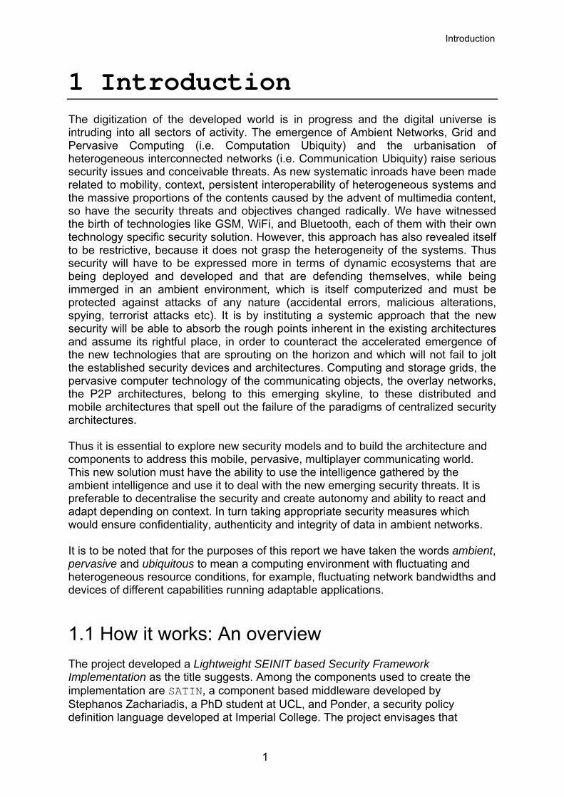
1 Introduction The digitization of the developed world is in progress and the digital universe is intruding into all sectors of activity. The emergence of Ambient Networks, Grid and Pervasive Computing (i.e. Computation Ubiquity) and the urbanisation of heterogeneous interconnected networks (i.e. Communication Ubiquity) raise serious security issues and conceivable threats. As new systematic inroads have been made related to mobility, context, persistent interoperability of heterogeneous systems and the massive proportions of the contents caused by the advent of multimedia content, so have the security threats and objectives changed radically. We have witnessed the birth of technologies like GSM, WiFi, and Bluetooth, each of them with their own technology specific security solution. However, this approach has also revealed itself to be restrictive, because it does not grasp the heterogeneity of the systems. Thus security will have to be expressed more in terms of dynamic ecosystems that are being deployed and developed and that are defending themselves, while being immerged in an ambient environment, which is itself computerized and must be protected against attacks of any nature (accidental errors, malicious alterations, spying, terrorist attacks etc). It is by instituting a systemic approach that the new security will be able to absorb the rough points inherent in the existing architectures and assume its rightful place, in order to counteract the accelerated emergence of the new technologies that are sprouting on the horizon and which will not fail to jolt the established security devices and architectures. Computing and storage grids, the pervasive computer technology of the communicating objects, the overlay networks, the P2P architectures, belong to this emerging skyline, to these distributed and mobile architectures that spell out the failure of the paradigms of centralized security architectures. Thus it is essential to explore new security models and to build the architecture and components to address this mobile, pervasive, multiplayer communicating world. This new solution must have the ability to use the intelligence gathered by the ambient intelligence and use it to deal with the new emerging security threats. It is preferable to decentralise the security and create autonomy and ability to react and adapt depending on context. In turn taking appropriate security measures which would ensure confidentiality, authenticity and integrity of data in ambient networks. It is to be noted that for the purposes of this report we have taken the words ambient, pervasive and ubiquitous to mean a computing environment with fluctuating and heterogeneous resource conditions, for example, fluctuating network bandwidths and devices of different capabilities running adaptable applications.
1.1 How it works: An overview The project developed a Lightweight SEINIT based Security Framework Implementation as the title suggests. Among the components used to create the implementation are SATIN, a component based middleware developed by Stephanos Zachariadis, a PhD student at UCL, and Ponder, a security policy definition language developed at Imperial College. The project envisages that
1
Introduction
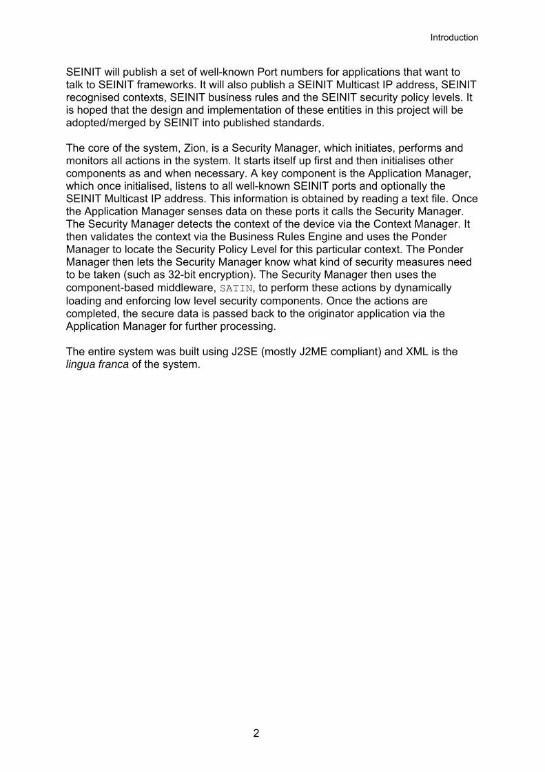
SEINIT will publish a set of well-known Port numbers for applications that want to talk to SEINIT frameworks. It will also publish a SEINIT Multicast IP address, SEINIT recognised contexts, SEINIT business rules and the SEINIT security policy levels. It is hoped that the design and implementation of these entities in this project will be adopted/merged by SEINIT into published standards. The core of the system, Zion, is a Security Manager, which initiates, performs and monitors all actions in the system. It starts itself up first and then initialises other components as and when necessary. A key component is the Application Manager, which once initialised, listens to all well-known SEINIT ports and optionally the SEINIT Multicast IP address. This information is obtained by reading a text file. Once the Application Manager senses data on these ports it calls the Security Manager. The Security Manager detects the context of the device via the Context Manager. It then validates the context via the Business Rules Engine and uses the Ponder Manager to locate the Security Policy Level for this particular context. The Ponder Manager then lets the Security Manager know what kind of security measures need to be taken (such as 32-bit encryption). The Security Manager then uses the component-based middleware, SATIN, to perform these actions by dynamically loading and enforcing low level security components. Once the actions are completed, the secure data is passed back to the originator application via the Application Manager for further processing. The entire system was built using J2SE (mostly J2ME compliant) and XML is the lingua franca of the system.
2
Related Work
2 Related Work There is not much out there in terms of complete security framework implementations or systems for pervasive computing. Pieces of the puzzle have been solved; for example, there is Ponder [20] which is a declarative language for specifying security policies and that also comes with associated tools for editing , compiling and managing policies. Then there are SATIN [11] and XMIDDLE [12] which are component-based middleware. However, few implemented systems exist that attempt to solve the full problem set. Aura [13] is one well known effort. Ubiquitous computing is seen as the next computing era in the next tens of years. Its applications could be multi-purpose. Its definition is rapidly evolving. There are many ongoing research efforts on technological functionality needed to achieve ubiquitous or even invisible computing. Due to its ubiquitous nature and the fact that personal identity, location, activity, wealth and even emotions are being data collected, security and privacy should be a concern. However, not many efforts are put into securing the ubiquitous environment. In an IFIP/IEEE symposium [7] it was suggested that if we want ubiquitous connectivity, we need to prepare to give up privacy. Marc in his paper ‘A privacy awareness system for ubiquitous computing environments’ [8] argues that tamper-proof technical protection mechanisms to solve all privacy threats will hardly be achievable. He proposes instead, building a privacy awareness system that allows data collectors to both announce and implement data usage policies, as well as providing data subjects with technical means to keep track of their personal information as it is stored, used, and eventually removed from the system. This in the very least creates a sense of accountability in a world of invisible computing devices. Campbell et al. in ‘Towards security and privacy for pervasive computing’ [9] outlines several security subsystem requirements for a pervasive system. Firstly he mentions that security subsystems should be transparent and unobtrusive to the user because that is the whole point of being pervasive anyway. Secondly, while pervasive computing integrates context and situational information, security aspects should not be exceptions. There is also a need to verify the authenticity and integrity of the context information acquired. This is sometimes necessary in order to thwart false context information obtained from rogue or malfunctioning sensors. The security subsystem also needs to be adaptable, flexible, customizable and able to negotiate security environments. Some examples of pervasive systems are outlined below.
2.1 Project Oxygen MIT’s Project Oxygen [14] has the vision that computation will be pervasive, like batteries, power sockets and the oxygen in the air we breathe. Oxygen identifies adaptation and change and information personalities as some of the important themes. Adaptation and change relates to the essential features of an increasingly
3
Related Work
dynamic world. Information personalities relate to the privacy, security, and form of our individual interactions with Oxygen.
2.2 Project Aura Project Aura [13] is about deploying and evaluating a large-scale system demonstrating the concept of a “personal information aura” that spans wearable, handheld, and desktop and infrastructure computers. This is based on the concept of a profile that moves with the user from his most recent to his current computing environment.
4
Objectives & Requirements
3 Objectives & Requirements The objective of our project is to build a J2ME compliant, lightweight SEINIT based Security Framework Implementation (POC - proof of concept) for Ambient Networks. This system will demonstrate that context based, high-level security policy driven secure data communications on a single device is feasible and can be implemented. The system will secure a chat conferencing application running on desktops and laptops. If time permits, the system will be extended further to incorporate the enforcement of security for voice and video conferencing applications and be extended so that it runs on handhelds such as PDAs and mobile phones. The system will demonstrate the use of component-based middleware and high level security policy languages.
3.1 A Scenario A consultant is chatting on a desktop, 10 mbps connection, with a client. It is a ZION desktop (with the current encryption level of 128 bits). He gets a call and is required to move to another building. He realises he cannot stop the chat though, since it is important. So he starts a session on his PDA. Since there is no WLAN in the room he is in, the PDA connects to the desktop via Bluetooth and uses the desktop's internet connection. This is a context switch which causes the encryption level to change to 32 bits. However, since the connection between the PDA and the desktop is via Bluetooth, the effective bandwidth is the Bluetooth bandwidth and not 10 mbps. When he reaches the next room, his PDA detects a WLAN signal and switches to the 6 mbps 802.11b effective bandwidth utilising the WLAN. This is a second context switch causing the encryption level to change to 64 bits. As he walks out of the building, the PDA loses the WLAN connection and picks up a GPRS signal through its GPRS terminal (third context switch). However, the existing Business Rules do not recognize a GPRS connection as a valid network context; hence ZION shuts down his chat session.
5
Objectives & Requirements
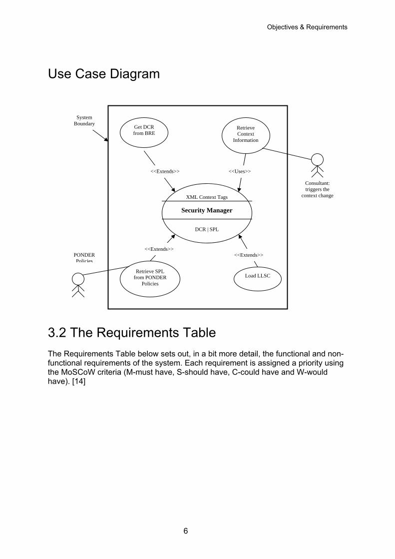
Use Case Diagram
System Boundary
XML Context Tags
Security Manager
DCR | SPL
Get DCR from BRE
<<Extends>> <<Extends>>
<<Uses>> <<Extends>>
Consultant: triggers the
context change
Retrieve Context
Information
3.2 The Rfunctiothe Mohave).
PONDER Policies
Retrieve SPL from PONDER
Policies Load LLSC
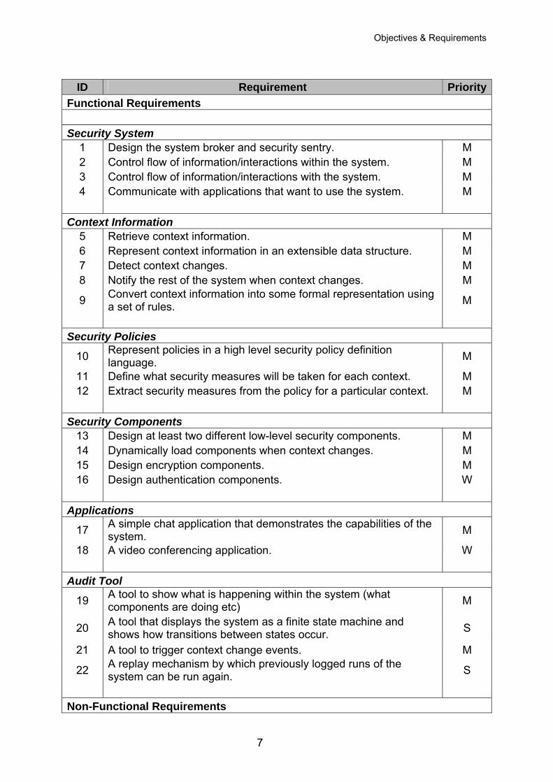
The Requirements Table equirements Table below sets out, in a bit more detail, the functional and non-nal requirements of the system. Each requirement is assigned a priority using SCoW criteria (M-must have, S-should have, C-could have and W-would
[14]
6
Objectives & Requirements
ID Requirement Priority
Functional Requirements Security System
1 Design the system broker and security sentry. M 2 Control flow of information/interactions within the system. M 3 Control flow of information/interactions with the system. M 4 Communicate with applications that want to use the system. M
Context Information 5 Retrieve context information. M 6 Represent context information in an extensible data structure. M 7 Detect context changes. M 8 Notify the rest of the system when context changes. M
9 Convert context information into some formal representation using a set of rules. M
Security Policies
10 Represent policies in a high level security policy definition language. M
11 Define what security measures will be taken for each context. M 12 Extract security measures from the policy for a particular context. M
Security Components 13 Design at least two different low-level security components. M 14 Dynamically load components when context changes. M 15 Design encryption components. M 16 Design authentication components. W
Applications
17 A simple chat application that demonstrates the capabilities of the system. M
18 A video conferencing application. W
Audit Tool
19 A tool to show what is happening within the system (what components are doing etc) M
20 A tool that displays the system as a finite state machine and shows how transitions between states occur. S
21 A tool to trigger context change events. M
22 A replay mechanism by which previously logged runs of the system can be run again. S
Non-Functional Requirements
7
Objectives & Requirements
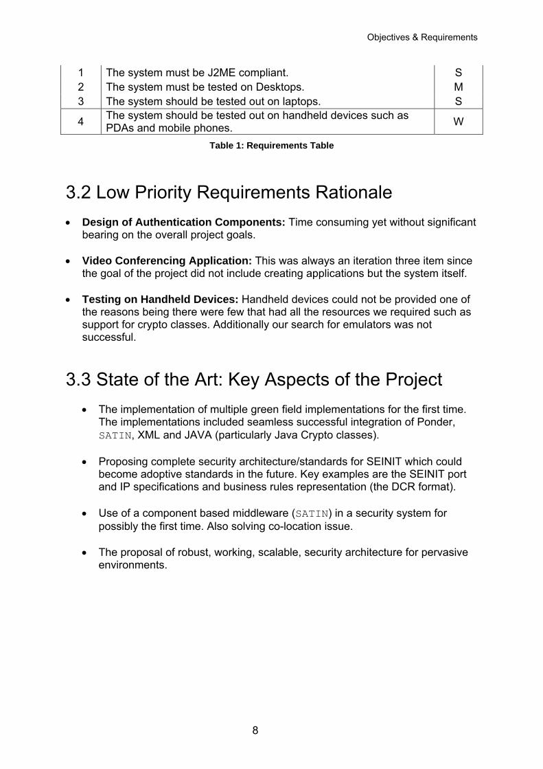
1 The system must be J2ME compliant. S 2 The system must be tested on Desktops. M 3 The system should be tested out on laptops. S
4 The system should be tested out on handheld devices such as PDAs and mobile phones. W
Table 1: Requirements Table
3.2 Low Priority Requirements Rationale • Design of Authentication Components: Time consuming yet without significant
bearing on the overall project goals.
• Video Conferencing Application: This was always an iteration three item since the goal of the project did not include creating applications but the system itself.
• Testing on Handheld Devices: Handheld devices could not be provided one of the reasons being there were few that had all the resources we required such as support for crypto classes. Additionally our search for emulators was not successful.
3.3 State of the Art: Key Aspects of the Project
• The implementation of multiple green field implementations for the first time. The implementations included seamless successful integration of Ponder, SATIN, XML and JAVA (particularly Java Crypto classes).
• Proposing complete security architecture/standards for SEINIT which could
become adoptive standards in the future. Key examples are the SEINIT port and IP specifications and business rules representation (the DCR format).
• Use of a component based middleware (SATIN) in a security system for
possibly the first time. Also solving co-location issue.
• The proposal of robust, working, scalable, security architecture for pervasive environments.
8
System Architecture
4 System Architecture
n
Business
Core
Auditing Tool n
ApplicationManager
Applicatio
P E O N N G D I E N R E
PonderMgr
Ponder XML
C E O N N G T I E N X E T
ContextR
Policy Editor
n n
XMLMgr
Middleware - SATIN
Engine
LLSC – 128 bit encrypter
LLSC – 32 bit encrypter
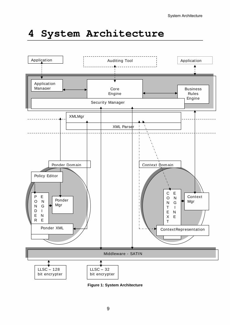
Figure 1: System Architecture
9
Applicatio
Rules Engine
XML Parser
Security Manager
Ponder Domai
Context DomaiContext Mgr
epresentation
System Architecture
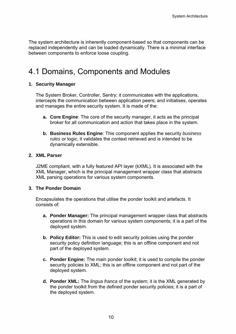
The system architecture is inherently component-based so that components can be replaced independently and can be loaded dynamically. There is a minimal interface between components to enforce loose coupling.
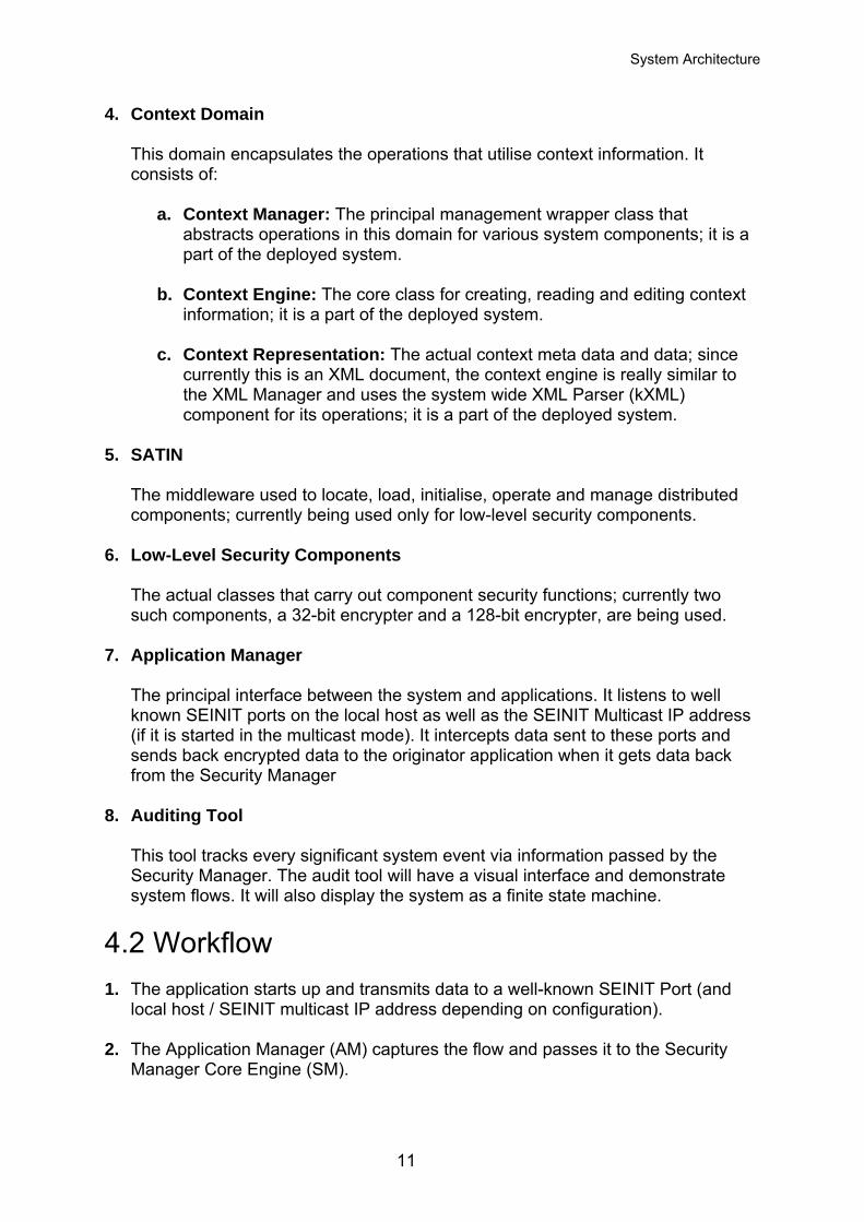
4.1 Domains, Components and Modules 1. Security Manager
The System Broker, Controller, Sentry; it communicates with the applications, intercepts the communication between application peers; and initialises, operates and manages the entire security system. It is made of the:
a. Core Engine: The core of the security manager, it acts as the principal broker for all communication and action that takes place in the system.
b. Business Rules Engine: This component applies the security business rules or logic; it validates the context retrieved and is intended to be dynamically extensible.
2. XML Parser
J2ME compliant, with a fully featured API layer (kXML). It is associated with the XML Manager, which is the principal management wrapper class that abstracts XML parsing operations for various system components.
3. The Ponder Domain Encapsulates the operations that utilise the ponder toolkit and artefacts. It consists of:
a. Ponder Manager: The principal management wrapper class that abstracts
operations in this domain for various system components; it is a part of the deployed system.
b. Policy Editor: This is used to edit security policies using the ponder security policy definition language; this is an offline component and not part of the deployed system.
c. Ponder Engine: The main ponder toolkit; it is used to compile the ponder security policies to XML; this is an offline component and not part of the deployed system.
d. Ponder XML: The lingua franca of the system; it is the XML generated by
the ponder toolkit from the defined ponder security policies; it is a part of the deployed system.
10
System Architecture
4. Context Domain This domain encapsulates the operations that utilise context information. It consists of:
a. Context Manager: The principal management wrapper class that
abstracts operations in this domain for various system components; it is a part of the deployed system.
b. Context Engine: The core class for creating, reading and editing context information; it is a part of the deployed system.
c. Context Representation: The actual context meta data and data; since
currently this is an XML document, the context engine is really similar to the XML Manager and uses the system wide XML Parser (kXML) component for its operations; it is a part of the deployed system.
5. SATIN The middleware used to locate, load, initialise, operate and manage distributed components; currently being used only for low-level security components.
6. Low-Level Security Components The actual classes that carry out component security functions; currently two such components, a 32-bit encrypter and a 128-bit encrypter, are being used.
7. Application Manager
The principal interface between the system and applications. It listens to well known SEINIT ports on the local host as well as the SEINIT Multicast IP address (if it is started in the multicast mode). It intercepts data sent to these ports and sends back encrypted data to the originator application when it gets data back from the Security Manager
8. Auditing Tool This tool tracks every significant system event via information passed by the Security Manager. The audit tool will have a visual interface and demonstrate system flows. It will also display the system as a finite state machine.
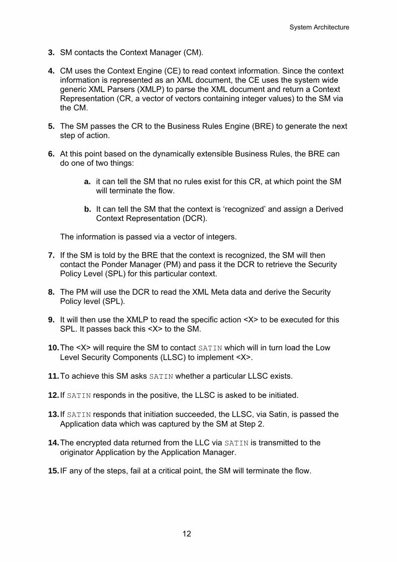
4.2 Workflow 1. The application starts up and transmits data to a well-known SEINIT Port (and
local host / SEINIT multicast IP address depending on configuration).
2. The Application Manager (AM) captures the flow and passes it to the Security Manager Core Engine (SM).
11
System Architecture
3. SM contacts the Context Manager (CM). 4. CM uses the Context Engine (CE) to read context information. Since the context
information is represented as an XML document, the CE uses the system wide generic XML Parsers (XMLP) to parse the XML document and return a Context Representation (CR, a vector of vectors containing integer values) to the SM via the CM.
5. The SM passes the CR to the Business Rules Engine (BRE) to generate the next
step of action. 6. At this point based on the dynamically extensible Business Rules, the BRE can
do one of two things:
a. it can tell the SM that no rules exist for this CR, at which point the SM will terminate the flow.
b. It can tell the SM that the context is ‘recognized’ and assign a Derived Context Representation (DCR).
The information is passed via a vector of integers.
7. If the SM is told by the BRE that the context is recognized, the SM will then contact the Ponder Manager (PM) and pass it the DCR to retrieve the Security Policy Level (SPL) for this particular context.
8. The PM will use the DCR to read the XML Meta data and derive the Security
Policy level (SPL). 9. It will then use the XMLP to read the specific action <X> to be executed for this
SPL. It passes back this <X> to the SM.
10. The <X> will require the SM to contact SATIN which will in turn load the Low Level Security Components (LLSC) to implement <X>.
11. To achieve this SM asks SATIN whether a particular LLSC exists. 12. If SATIN responds in the positive, the LLSC is asked to be initiated.
13. If SATIN responds that initiation succeeded, the LLSC, via Satin, is passed the
Application data which was captured by the SM at Step 2.
14. The encrypted data returned from the LLC via SATIN is transmitted to the originator Application by the Application Manager.
15. IF any of the steps, fail at a critical point, the SM will terminate the flow.
12
System Architecture
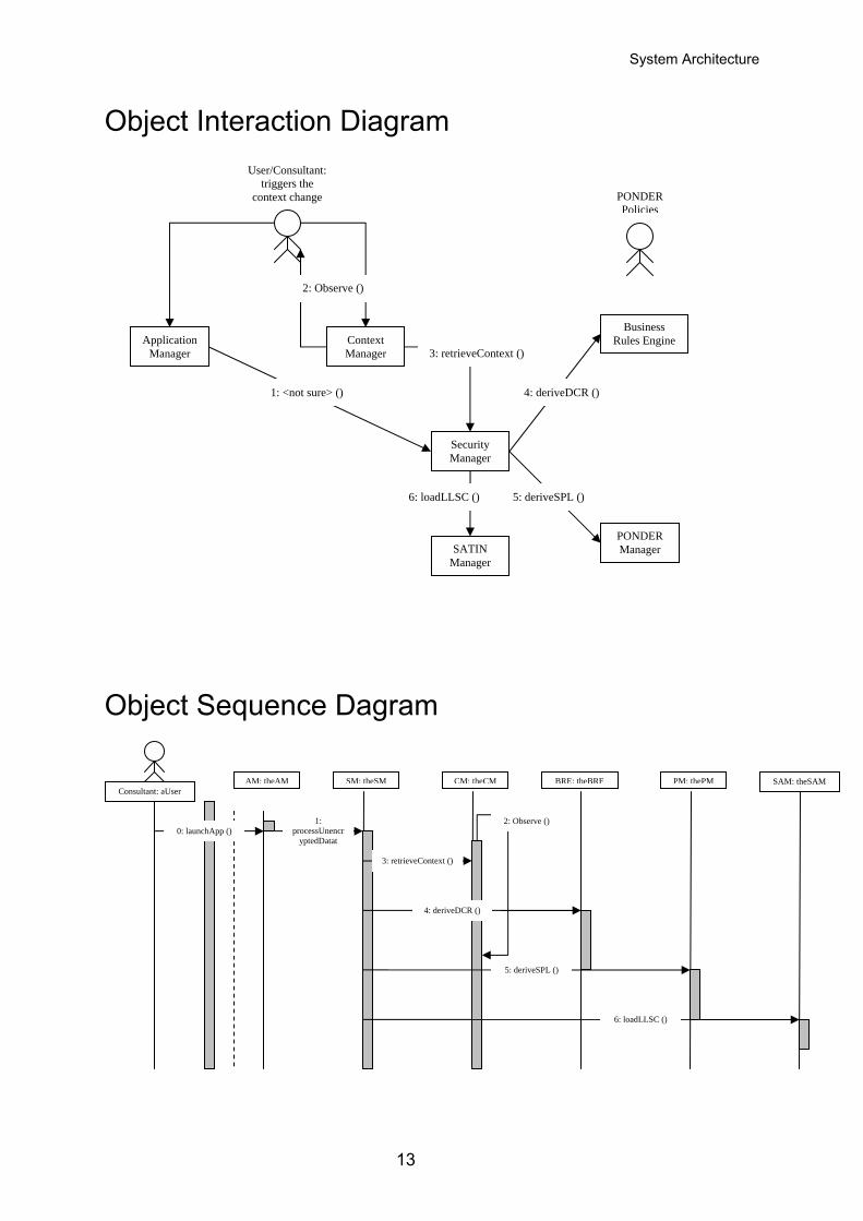
Object Interaction Diagram
User/Consultant: triggers the
context change PONDER Policies
Object Sequence Dagram
Consultant: aUser SM: theSM PM: thePMAM: theAM CM: theCM BRE: theBRE SAM: theSAM
0: launchApp () 1:
processUnencryptedDatat
2: Observe ()
3: retrieveContext ()
4: deriveDCR ()
5: deriveSPL ()
6: loadLLSC ()
Context Manager
Security Manager
Application Manager
PONDER Manager
Business Rules Engine
SATIN Manager
2: Observe ()
3: retrieveContext ()
1: <not sure> () 4: deriveDCR ()
6: loadLLSC () 5: deriveSPL ()
13
System Architecture
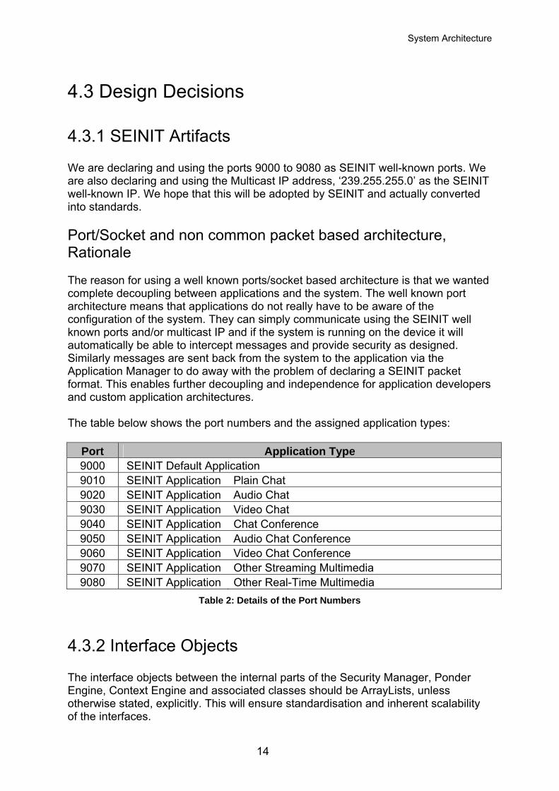
4.3 Design Decisions
4.3.1 SEINIT Artifacts We are declaring and using the ports 9000 to 9080 as SEINIT well-known ports. We are also declaring and using the Multicast IP address, ‘239.255.255.0’ as the SEINIT well-known IP. We hope that this will be adopted by SEINIT and actually converted into standards. Port/Socket and non common packet based architecture, Rationale The reason for using a well known ports/socket based architecture is that we wanted complete decoupling between applications and the system. The well known port architecture means that applications do not really have to be aware of the configuration of the system. They can simply communicate using the SEINIT well known ports and/or multicast IP and if the system is running on the device it will automatically be able to intercept messages and provide security as designed. Similarly messages are sent back from the system to the application via the Application Manager to do away with the problem of declaring a SEINIT packet format. This enables further decoupling and independence for application developers and custom application architectures. The table below shows the port numbers and the assigned application types:
Port Application Type 9000 SEINIT Default Application 9010 SEINIT Application Plain Chat 9020 SEINIT Application Audio Chat 9030 SEINIT Application Video Chat 9040 SEINIT Application Chat Conference 9050 SEINIT Application Audio Chat Conference 9060 SEINIT Application Video Chat Conference 9070 SEINIT Application Other Streaming Multimedia 9080 SEINIT Application Other Real-Time Multimedia
Table 2: Details of the Port Numbers
4.3.2 Interface Objects The interface objects between the internal parts of the Security Manager, Ponder Engine, Context Engine and associated classes should be ArrayLists, unless otherwise stated, explicitly. This will ensure standardisation and inherent scalability of the interfaces.
14
System Architecture
4.3.3 XML Parser Currently, the XML Parser chosen is kXML. This is principally because it is J2ME compliant and has a low memory operation cost (ideal for PDAs and the like).
4.3.4 Code Standards All code SHOULD be J2ME CDC profile compliant. This is to ensure easy device portability.
4.4 Architecture Model The entire system will be co-located on the same device that the application is running on. This is to ensure end-point/device security as compared to the more involved, complex and expensive application security.
4.4.1 Architecture Characteristics 1. The system has been architected to be inherently extensible and scalable, right
down to dynamic component loading of all components (except the middleware) if necessary; dynamic interface scalability and dynamic business rules loading.
2. The system can be debugged easily due to capturing and logging of every significant system event via the audit tool.
3. The system, though operating to implement end-point/device security, is scalable
enough to allow for components and external interfaces necessary for application security, such as a Public Trust Infrastructure based application security via user authentication and validation.
4.5 Assumptions in System The key assumptions about the system are as follows: • All applications wanting to use the system are running on the same host/device
as the system. This follows from our goal of end-point as opposed to application security.
• There is enough memory/disk space available to load the system. • The device running the system is capable of :
15
System Architecture
running J2ME applications, supporting java cryptography classes, supporting XML parsing and manipulation and supporting a standard network interface and related operations.
• Shared key generation mechanism already exists. • Intermittent network connectivity does not happen. We will not consider power
issues. • Only basic security service such as encryption using a shared key will be
considered. • We will not deal with context detection or retrieval devices, like a Global
Positioning System (hardware and software). So long as they can create a context representation that conforms to our context representation format, they can be plugged into our system seamlessly.
16
Tools & Technologies
5 Tools and Technologies
5.1 Security Policy Language Tools One of the requirements stated for the project was a need for a way to specify security policies by use of a high level, semantic language (i.e. A Security Policy Language or SPL). These high level SPLs will provide the end user with a tool for expressing policies in an environment-independent way. So it was decided that an existing SPL would be chosen and used. SPLs can be divided into two main categories:
• Those concentrating on security specification (i.e. termed security policies) with emphasis on role-based access control, and
• Those specifying the actions that must be executed in response to events which we term management policies.
For our purposes we are more concerned with management policies since our security system is designed to take action in light of context change i.e. the triggering event. The choice of SPLs was narrowed down to three SPLs. A brief description of the capabilities and services provided by them is given below, followed by the rationale behind the selection of Ponder.
5.1.1 SPL The Security Policy Language (SPL) [15] is an event-driven policy language that supports access-control, history-based and obligation-based policies. SPL is implemented by an event monitor that for each event decides whether to allow, disallow or ignore the event. Events in SPL are synonymous with action calls on target objects, and can be queried to determine the subject who initiated the event, the target on which the event is called, and attribute values of the subject, target and the event itself. SPL supports two types of sets to group the objects on which policies apply: groups and categories. Groups are sets defined by explicit insertion and removal of their elements, and categories are sets defined by classification of entities according to their properties. The building blocks of policies in SPL are constraint rules which can be composed using specific tri-value algebra with three logic operators: and, or and not. A simple constraint rule is comprised of two logical binary expressions, one to establish the domain of applicability and another to decide on the acceptability of the event. Note that conflicts between positive and negative authorisation policies are avoided by using the tri-value algebra to prioritise policies when they are combined.
17
Tools & Technologies
SPL allows definition of policies as classes which allow parameterised instantiation. Further re-use of specifications is supported through inheritance between policies. A policy can inherit the specifications of another policy and override certain rules or sets. Policy constructs can also be used to model roles, in which case sets in the policy specify the users allowed to play the role and those playing the role. Rules or other nested policies inside a role policy specify the access rights associated with the role. SPL provides the ability to hierarchically compose policies by instantiating them inside other policies, thus enabling the specification of libraries of common security policies that can be used as building blocks for more complex policies.
5.1.2 XACML XACML [16] is an XML specification for expressing policies for information access over the Internet and is being defined by the Organisation for the Advancement of Structured Information Standards (OASIS) technical committee. The language provides XML with a sophisticated access control mechanism that enables the initiator not only to securely browse XML documents but also to securely update each document element. Similar to existing policy languages, XACML is used to specify a subject-target-action-condition oriented policy in the context of a particular XML document. The notion of subject comprises identity, group, and role and the granularity of target objects is as fine as single elements within the document. The language supports roles, which are the same as groups, and are defined as collections of attributes relevant to a principal. XACML includes conditional authorisation policies, as well as policies with external post-conditions to specify actions that must be executed prior to permitting an access. e.g. “A physician may read any record and write any medical element for which he or she is the designated primary care physician, provided an email notice is sent to the patient or the parent/guardian, in case the patient is under 16”.
5.1.3 Ponder The Ponder language [20] for specifying Management and Security policies evolved out of work on policy management at Imperial College. Ponder is a declarative, object-oriented language that can be used to specify both security and management policies. Ponder authorisation policies can be implemented using various access control mechanisms for firewalls, operating systems, databases and Java. For example, if servers used to store data in the AI research group are Linux based while servers in other departments are Windows 2000 based, and then appropriate code will be generated based on the type of server. Preliminary implementations exist for translating Ponder policies onto various access control platforms. These include a Java back-end which transforms Ponder authorization policies into access control policies for the Java platform. Ponder also supports obligation policies that are event triggered condition-action rules for policy based management of networks and distributed systems. These types of policies are of particular importance to the team as the system being built is an event driven one and the policies that will be written for the system will essentially
18
Tools & Technologies
be obligation policies to start of with. A complete Ponder Policy brief with examples relating to the team’s work can be found in Appendix C. Ponder can also be used for security management activities such as registration of users or logging and auditing events for dealing with access to critical resources or security violations. It provides a common unified framework for specifying management policy for heterogeneous platforms. Key concepts of the language include domains to group the object to which policies apply, roles to group policies relating to a position in an organisation, relationships to define interactions between roles and management structures to define a configuration of roles and relationships pertaining to an organisational unit such as a department. Ponder comes with a complete toolkit which consists of the following:
• Domain Browser • Compiler • Policy Editor • Management Console Tool
The Policy Editor and Compiler were of particular interest to the team. The Ponder compiler maps policies to low-level representations (e.g. Java) suitable for the underlying system or into XML for transfer around the network. The Ponder editor provides an IDE for writing security policies providing templates (i.e. for Authorisation, Obligation Policies etc.) to facilitate efficient policy generation.
5.1.4 Ponder Rationale When researching SPLs the team resolved to select an SPL which would be as flexible and generic as possible. The criteria are as follows.
• Provide a framework which allows a user to specify both Security and Management Policies which encompass the entire spectrum of policy types i.e. positive and Negative Authorisation, Obligation, Delegation Policies etc.)
• Furthermore the team was looking for a framework which would allow the mapping of these high level policies to low level security mechanisms efficiently and with minimum fuss.
• Finally since the decision was made to use an existing third party SPL, the team felt that communication between the developer of the selected SPL and the team was of utmost importance and would also be a critical plus point. This would allow the team to synthesize and understand the working of the selected language and more importantly provide a line of support in case of critical crux.
Keeping the above criteria in mind the team decided to use Ponder to specify the policies associated with this project. Most of the other work researched by the team relates more to security and none include the range of policies covered in Ponder, lacking the level of flexibility and extensibility features of Ponder. Ponder caters for the specification of management and security policies including authorisation, filter,
19
Tools & Technologies
refrain and delegation policies for specifying access control and obligation policies to specify management actions. As mentioned earlier it supports a means of specifying enterprise-wide security policy that can then be translated onto various security implementation mechanisms. The object-oriented features of Ponder allow user-defined types of policies to be specified and then instantiated multiple times with different parameters. This provides for flexibility and extensibility while maintaining a structured specification that can be, in large part, checked at compile time. Meta-policies in Ponder provide a very powerful tool in specifying application specific constraints on sets of policies. Finally, Ponder is declarative which aids in the analysis of policies. All these facts helped the team in agreeing that Ponder is the closest match to the set criteria. The team does understand that the criteria set, far exceeds the required criteria of the required SPL for the given system. However given the nature of technology today and its rapid growth the team believes that the system must be as scalable and generic as possible to facilitate this growth. Thus the selected SPL must reflect this fact. In comparison, SPL does not cater for specification of delegation of access rights between subjects, and there is no explicit support for specifying roles. Also the authors claim that SPL hierarchically composed policies help restrict the scope of conflicts between policies, however this is not clear as there may be possible conflicts across policy hierarchies. XACML on the other hand primarily provides only access control policies. The granularity of this access control is good but the policies are rather verbose and not really aimed at human interpretation. Here the team would like to emphasize that a high level “semantic” language to specify policies is required. In addition, the language model does not include a way of grouping policies. Note that XACML is intended to be used in conjunction with SAML (security assertion and mark-up language) assertions and messages, and can thus also be applied to certificate-based authorisations. Having said that though, the team felt the use of SAML in conjunction with XACML would beckon further research introducing new risk elements to the project. Finally since Ponder is an Imperial College effort the team felt more confident establishing support level contact with a Ponder developer. In fact, during the project lifecycle the team was in contact with a Ponder developer, primarily via email, who was instrumental in helping the team remedy some critical installation and Ponder Compiler issues.
5.2 SATIN One of the main requirements of the system is that it should be able to enforce new security measures when context change occurs. In other words the system needs to re-organise dynamically in response to changes in connectivity and in the physical environment. A self-organising system is therefore required so that it can adapt to accommodate changes in context.
20
Tools & Technologies
SATIN (System Adaptation Targeting Integrated Networks) [11] is a lightweight component model, which represents a system as a set of interoperable local components. It allows for dynamic adaptation of the system’s behaviour, by exploiting logical mobility. A SATIN component encapsulates particular functionality, such as, for instance, an encryption scheme. Attributes are used to describe a component. An attribute is simply a tuple containing a key and a value. The set of attributes make up a component’s properties. The central component of SATIN is the container component, which acts as the registry of components that are installed in the system. A registrar is responsible for loading components and adding them to the registry. SATIN provides an advertising and discovery service. Components that wish to advertise their presence to the environment are advertised components. An advertiser component takes the message of advertised components and uses it to advertise them. Similarly, the discovery service allows components to register listeners with it, to be notified when a specific component becomes available. Matching is done using a set of attributes provided by the requesting component. All of the above features of SATIN make it ideal for this security framework. All components in the system will be represented as SATIN components with a set of properties. These components would register themselves with the SATIN container and advertise their presence. On context change the system would re-organise i.e. appropriate components would be dynamically loaded using the discovery service based on attributes defined in the security policy. (SATIN is the work of a PhD student, Stefanos Zachiaradis, at UCL. This will be the first time that his middleware has been used within a project of this nature and will therefore serve to extensively test it and in the end provide useful feedback.)
5.3 XML Parser XML is the lingua franca of the system. Our system needs to be extensible. XML provides easy human readability and extensibility into complicated information. Therefore it was decided to use XML in a system-wide basis. XML is used to represent context data and to represent security policies internally.
5.3.1 Choosing a Parser An XML parser is required in order to parse and manipulate XML data. Simple API for XML (SAX) and Document Object Model (DOM) are the standard APIs for XML parser and they are supported by JDK 1.4+. SAXDOMIX combines the advantages of SAX and DOM, allowing application to get SAX events or DOM sub-trees and so
21
Tools & Technologies
is powerful and flexible. Since scalability of DOM is limited by the memory of the computer, it would not be a good choice for deploying onto mobile devices. So we eliminated DOM and SAXDOMIX from our candidate list of parsers. In order to further help in choosing a parser, some benchmark results [21] [22] were analysed to compare performance of various parse methods and parser implementations. Five SAX2 parsers and two pull parsers on Java Runtime Environment 1.3.1 were tested and their average parse times were compared. The results show that the pull parsers performed extremely well with the small documents, beating all the SAX2 parsers except the new Piccolo parser [22]. As mobile devices are generally tight on memory resources, it is good that pull parsers allow the application designer to control parsing by saving necessary states only. Though no validation is supported as of this writing, adding a layering approach suggested by [22] should provide validation. Two pull parsers kXML [23] and XPP3 [24], both support everything from J2ME (Java 2 Micro Edition) to J2EE (Java 2 Enterprise Edition). Other parsers compatible with J2ME have been considered, like nanoXML [25]. However, it was found that these are not as common as kXML which uses a common API for XML Pull Parsing called XMLPull. Therefore, it was decided to use kXML as the system wide XML Parser.
5.4 Programming Platform: J2ME To demonstrate ubiquity of our system concept, we decided to target multiple environments including the desktop and handheld environment. Nowadays handhelds have wireless and ad-hoc networking capability and so can participate in pervasive environments. We decided to write code in such a way that the code can be portable from a desktop environment to a handheld environment. The code that we write in the first iteration should be able to be ported to the second iteration without much difficulty. Handhelds selling in the market have used three main operating systems including Microsoft Windows Mobile, Palm OS, and Symbian OS and each operating system comes with its own native API. Java has the advantage of being easily portable between platforms. The Java 2 Platform Micro Edition (J2ME), in particular, provides a flexible environment for applications running on many other consumer devices, such as mobile phones, TV set-top boxes, as well as a broad range of embedded devices. Although most applications running on Java 2 Standard Edition (J2SE) virtual machine can be ported directly to mobile devices, doing so will often lead to unacceptable performance and poor usability. It should be noted that mobile devices are limited in hardware capability, with CPU speeds as slow as 20MHz and RAM as little as 100KB. In this case, we have to carefully evaluate the features we need, thoroughly optimize our code, and live with limited framework support. [27] CLDC and MIDP standard libraries are designed from the ground up as lightweight components. Nevertheless, the team does not have experience in using those
22
Tools & Technologies
libraries. Using it will incur a learning curve. Therefore given the tight time constraint, we chose to implement applications on desktop in the first iteration. In the future, most of the code can be ported directly to a CDC-compliant environment which can run on high-end palmtop devices. This decision means that we can reuse the code developed in iteration one. Among the various configurations supported in J2ME, we chose to support only Connected Device Configuration (CDC). Using CDC, if we avoid the use of certain Java packages from J2SE version 1.3.1, we can write code that can be run on both desktop and handheld environments. The list of Java packages that are supported in CDC are shown in [28]. Selection of software development packages has avoided the use of javax.swing, java.applet, java.util.logging. Due to time constraint, however, we use javax.crypto classes to load encryption components. By designing according to the foundation profile, our system will also run on personal profile. We achieved J2ME CDC compatibility except security encryption classes. This will be part of our future work. Our code has been written so as to run on any J2ME enabled device/environment running the CDC profile and having support for Java crypto classes (which are currently not supported on any current profiles, being a J2SE 1.4 feature).
23
Design & Implementation
6 Design and Implementation This section outlines in detail, the design and implementation of the various parts of the system as explained in the System Architecture.
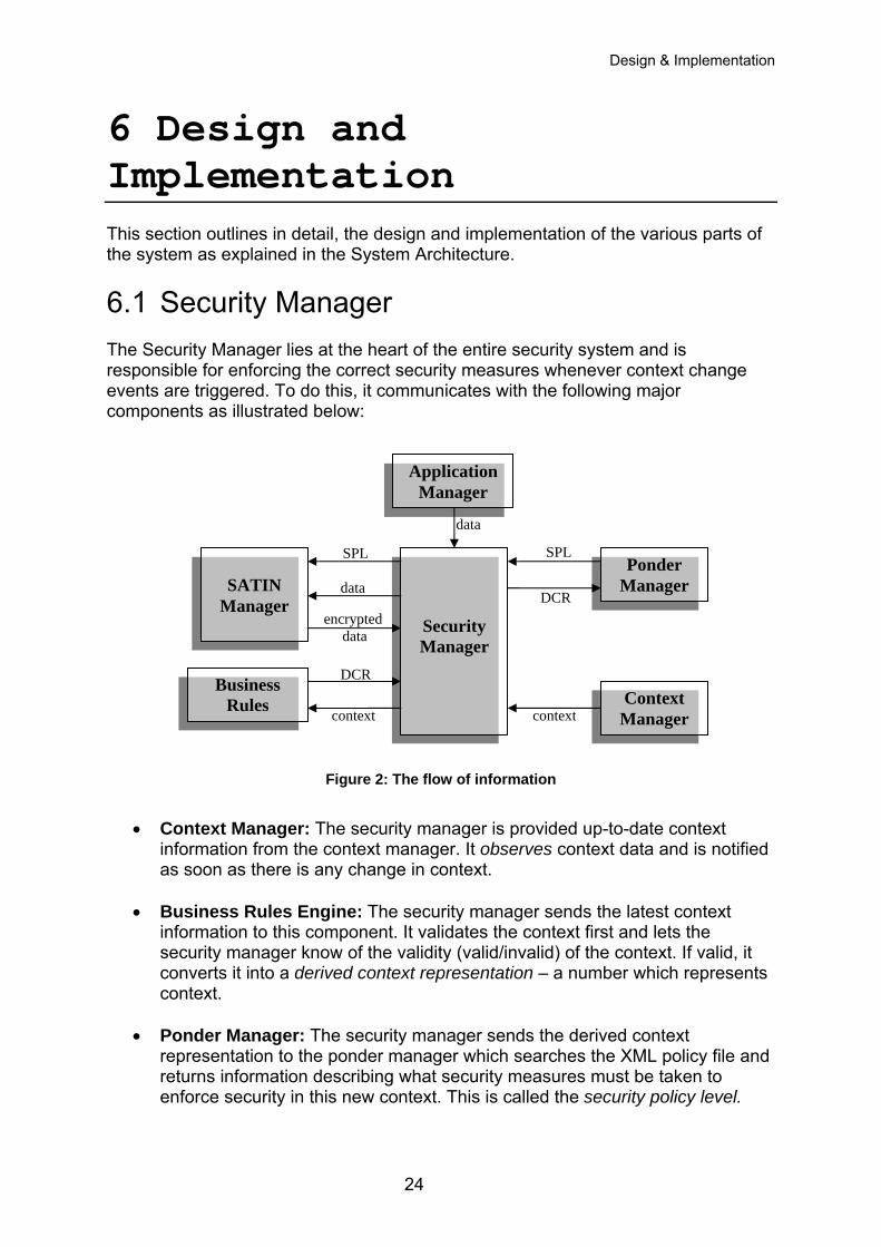
6.1 Security Manager The Security Manager lies at the heart of the entire security system and is responsible for enforcing the correct security measures whenever context change events are triggered. To do this, it communicates with the following major components as illustrated below:
data
SPLSPL
Figure 2: The flow of information
• Context Manager: The security manager is provided up-to-date context
information from the context manager. It observes context data and is notified as soon as there is any change in context.
• Business Rules Engine: The security manager sends the latest context
information to this component. It validates the context first and lets the security manager know of the validity (valid/invalid) of the context. If valid, it converts it into a derived context representation – a number which represents context.
• Ponder Manager: The security manager sends the derived context representation to the ponder manager which searches the XML policy file and returns information describing what security measures must be taken to enforce security in this new context. This is called the security policy level.
encrypted data
dataDCR
DCR
context context
Security Manager
Context Manager
Ponder Manager
SATIN
Manager
Application Manager
Business Rules
24
Design & Implementation
• SATIN Manager: The security manager sends the security policy level to the Satin Manager which uses the discovery service to dynamically load a suitable low-level security component to make the system secure.
• Application Manager: The application manager listens to SEINIT well-known ports and the SEINIT Multicast IP if started in the multicast mode. It intercepts data being sent by applications to these ports, IP/port and passes the data on to the security manager. When it received data back from the security manager, it passes it back to the originator application at the port and/or IP/Port it got the data from.
When the system starts, the security manger is the first to be initialised. It in turn loads each of the other components and exits the system if at any stage during the flow any of the components that need to be initialised or working are not present or non-functional. It serves as the one point of entry and exit from the system. It implements the basic security policy of a gatekeeper i.e. “If I don’t know you, I won’t let you through”. Therefore the information sent to it from the Application Manager is returned to it if and only if a valid context exists, a valid security policy level exists and also a valid security action based on the policy has been executed on the intercepted data.
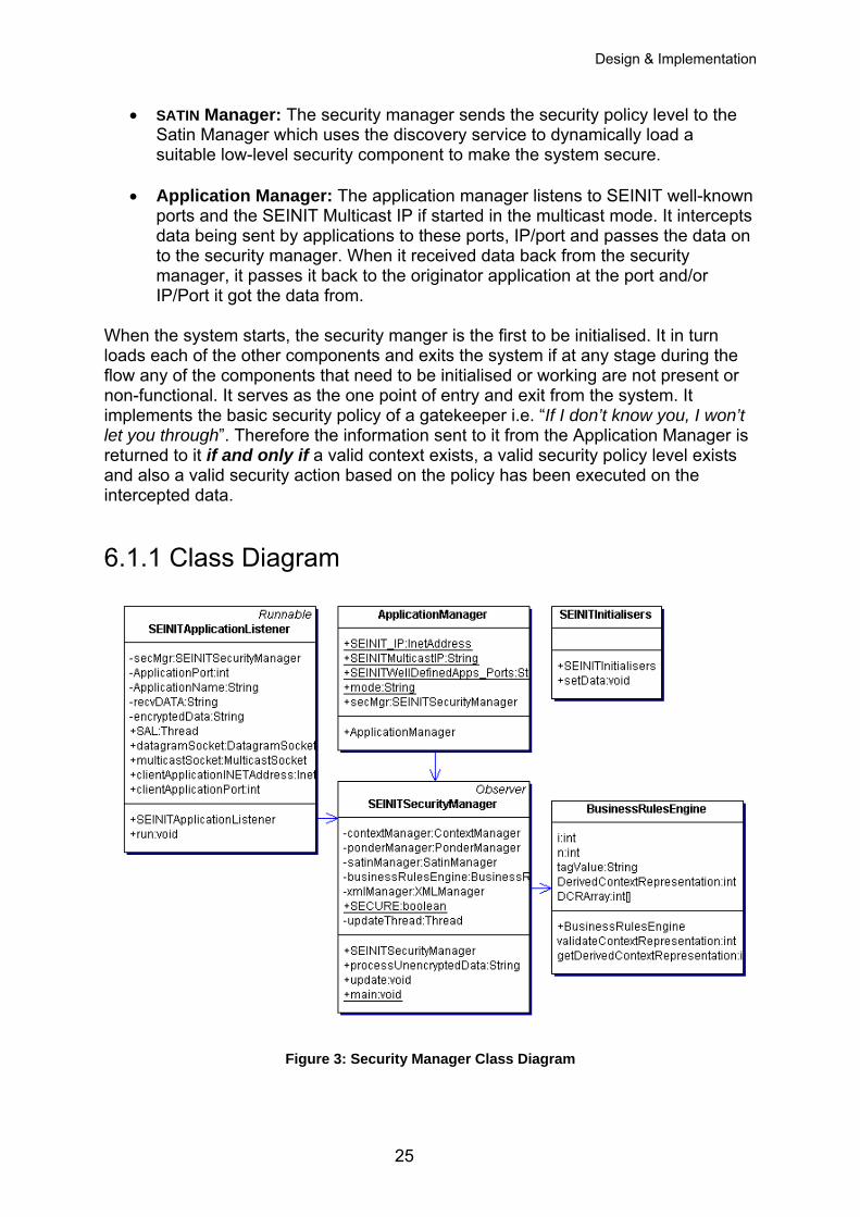
6.1.1 Class Diagram
Figure 3: Security Manager Class Diagram
25
Design & Implementation
The diagram above shows the class diagram for the Security Manager package.
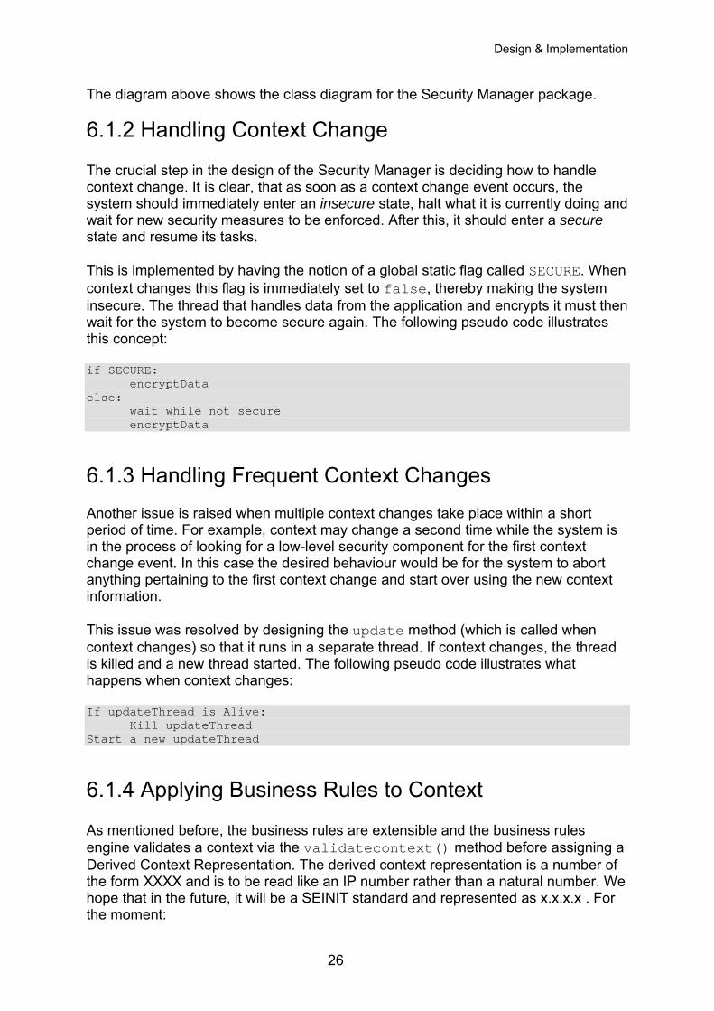
6.1.2 Handling Context Change The crucial step in the design of the Security Manager is deciding how to handle context change. It is clear, that as soon as a context change event occurs, the system should immediately enter an insecure state, halt what it is currently doing and wait for new security measures to be enforced. After this, it should enter a secure state and resume its tasks. This is implemented by having the notion of a global static flag called SECURE. When context changes this flag is immediately set to false, thereby making the system insecure. The thread that handles data from the application and encrypts it must then wait for the system to become secure again. The following pseudo code illustrates this concept: if SECURE: encryptData else:
wait while not secure encryptData
6.1.3 Handling Frequent Context Changes Another issue is raised when multiple context changes take place within a short period of time. For example, context may change a second time while the system is in the process of looking for a low-level security component for the first context change event. In this case the desired behaviour would be for the system to abort anything pertaining to the first context change and start over using the new context information. This issue was resolved by designing the update method (which is called when context changes) so that it runs in a separate thread. If context changes, the thread is killed and a new thread started. The following pseudo code illustrates what happens when context changes: If updateThread is Alive: Kill updateThread Start a new updateThread
6.1.4 Applying Business Rules to Context As mentioned before, the business rules are extensible and the business rules engine validates a context via the validatecontext() method before assigning a Derived Context Representation. The derived context representation is a number of the form XXXX and is to be read like an IP number rather than a natural number. We hope that in the future, it will be a SEINIT standard and represented as x.x.x.x . For the moment:
26
Design & Implementation
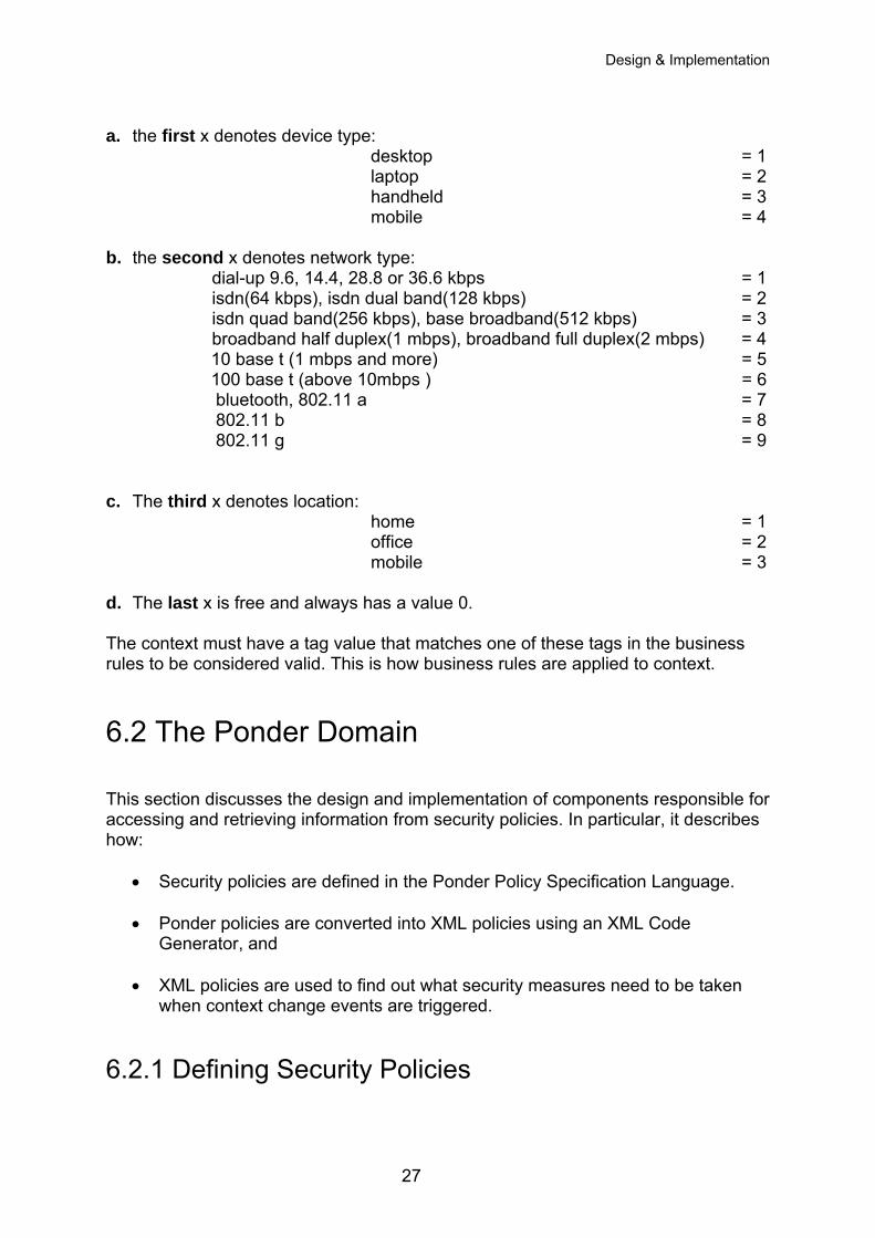
a. the first x denotes device type:
desktop = 1 laptop = 2 handheld = 3 mobile = 4
b. the second x denotes network type: dial-up 9.6, 14.4, 28.8 or 36.6 kbps = 1
isdn(64 kbps), isdn dual band(128 kbps) = 2 isdn quad band(256 kbps), base broadband(512 kbps) = 3 broadband half duplex(1 mbps), broadband full duplex(2 mbps) = 4 10 base t (1 mbps and more) = 5 100 base t (above 10mbps ) = 6 bluetooth, 802.11 a = 7 802.11 b = 8 802.11 g = 9
c. The third x denotes location: home = 1
office = 2 mobile = 3 d. The last x is free and always has a value 0. The context must have a tag value that matches one of these tags in the business rules to be considered valid. This is how business rules are applied to context.
6.2 The Ponder Domain This section discusses the design and implementation of components responsible for accessing and retrieving information from security policies. In particular, it describes how:
• Security policies are defined in the Ponder Policy Specification Language.
• Ponder policies are converted into XML policies using an XML Code Generator, and
• XML policies are used to find out what security measures need to be taken when context change events are triggered.
6.2.1 Defining Security Policies
27
Design & Implementation
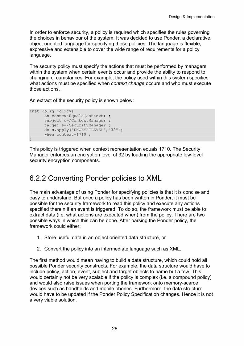
In order to enforce security, a policy is required which specifies the rules governing the choices in behaviour of the system. It was decided to use Ponder, a declarative, object-oriented language for specifying these policies. The language is flexible, expressive and extensible to cover the wide range of requirements for a policy language. The security policy must specify the actions that must be performed by managers within the system when certain events occur and provide the ability to respond to changing circumstances. For example, the policy used within this system specifies what actions must be specified when context change occurs and who must execute those actions. An extract of the security policy is shown below: inst oblig policy{ on contextEquals(context) ; subject c=/ContextManager ; target s=/SecurityManager ; do s.apply("ENCRYPTLEVEL","32"); when context=1710 ; } This policy is triggered when context representation equals 1710. The Security Manager enforces an encryption level of 32 by loading the appropriate low-level security encryption components.
6.2.2 Converting Ponder policies to XML The main advantage of using Ponder for specifying policies is that it is concise and easy to understand. But once a policy has been written in Ponder, it must be possible for the security framework to read this policy and execute any actions specified therein if an event is triggered. To do so, the framework must be able to extract data (i.e. what actions are executed when) from the policy. There are two possible ways in which this can be done. After parsing the Ponder policy, the framework could either:
1. Store useful data in an object oriented data structure, or
2. Convert the policy into an intermediate language such as XML. The first method would mean having to build a data structure, which could hold all possible Ponder security constructs. For example, the data structure would have to include policy, action, event, subject and target objects to name but a few. This would certainly not be very scalable if the policy is complex (i.e. a compound policy) and would also raise issues when porting the framework onto memory-scarce devices such as handhelds and mobile phones. Furthermore, the data structure would have to be updated if the Ponder Policy Specification changes. Hence it is not a very viable solution.
28
Design & Implementation
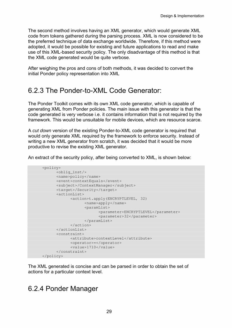
The second method involves having an XML generator, which would generate XML code from tokens gathered during the parsing process. XML is now considered to be the preferred technique of data exchange worldwide. Therefore, if this method were adopted, it would be possible for existing and future applications to read and make use of this XML-based security policy. The only disadvantage of this method is that the XML code generated would be quite verbose. After weighing the pros and cons of both methods, it was decided to convert the initial Ponder policy representation into XML
6.2.3 The Ponder-to-XML Code Generator: The Ponder Toolkit comes with its own XML code generator, which is capable of generating XML from Ponder policies. The main issue with this generator is that the code generated is very verbose i.e. it contains information that is not required by the framework. This would be unsuitable for mobile devices, which are resource scarce. A cut down version of the existing Ponder-to-XML code generator is required that would only generate XML required by the framework to enforce security. Instead of writing a new XML generator from scratch, it was decided that it would be more productive to revise the existing XML generator. An extract of the security policy, after being converted to XML, is shown below: <policy> <oblig_inst/> <name>policy</name> <event>contextEquals</event> <subject>/ContextManager</subject> <target>/Security</target> <actionList> <action>t.apply(ENCRYPTLEVEL, 32) <name>apply</name> <paramList> <parameter>ENCRYPTLEVEL</parameter> <parameter>32</parameter> </paramList> </action> </actionList> <constraint> <attribute>contextLevel</attribute> <operator>=</operator> <value>1710</value> </constraint> </policy> The XML generated is concise and can be parsed in order to obtain the set of actions for a particular context level.
6.2.4 Ponder Manager
29
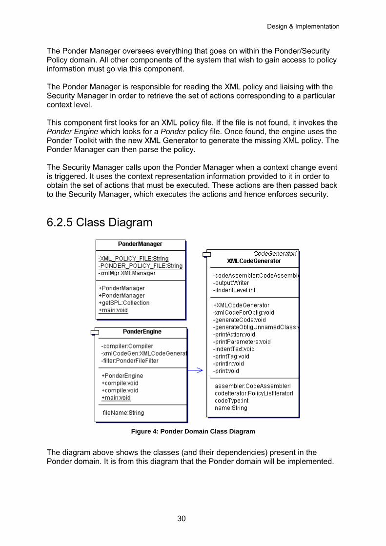
Design & Implementation
The Ponder Manager oversees everything that goes on within the Ponder/Security Policy domain. All other components of the system that wish to gain access to policy information must go via this component. The Ponder Manager is responsible for reading the XML policy and liaising with the Security Manager in order to retrieve the set of actions corresponding to a particular context level. This component first looks for an XML policy file. If the file is not found, it invokes the Ponder Engine which looks for a Ponder policy file. Once found, the engine uses the Ponder Toolkit with the new XML Generator to generate the missing XML policy. The Ponder Manager can then parse the policy. The Security Manager calls upon the Ponder Manager when a context change event is triggered. It uses the context representation information provided to it in order to obtain the set of actions that must be executed. These actions are then passed back to the Security Manager, which executes the actions and hence enforces security.
6.2.5 Class Diagram
Figure 4: Ponder Domain Class Diagram
The diagram above shows the classes (and their dependencies) present in the Ponder domain. It is from this diagram that the Ponder domain will be implemented.
30
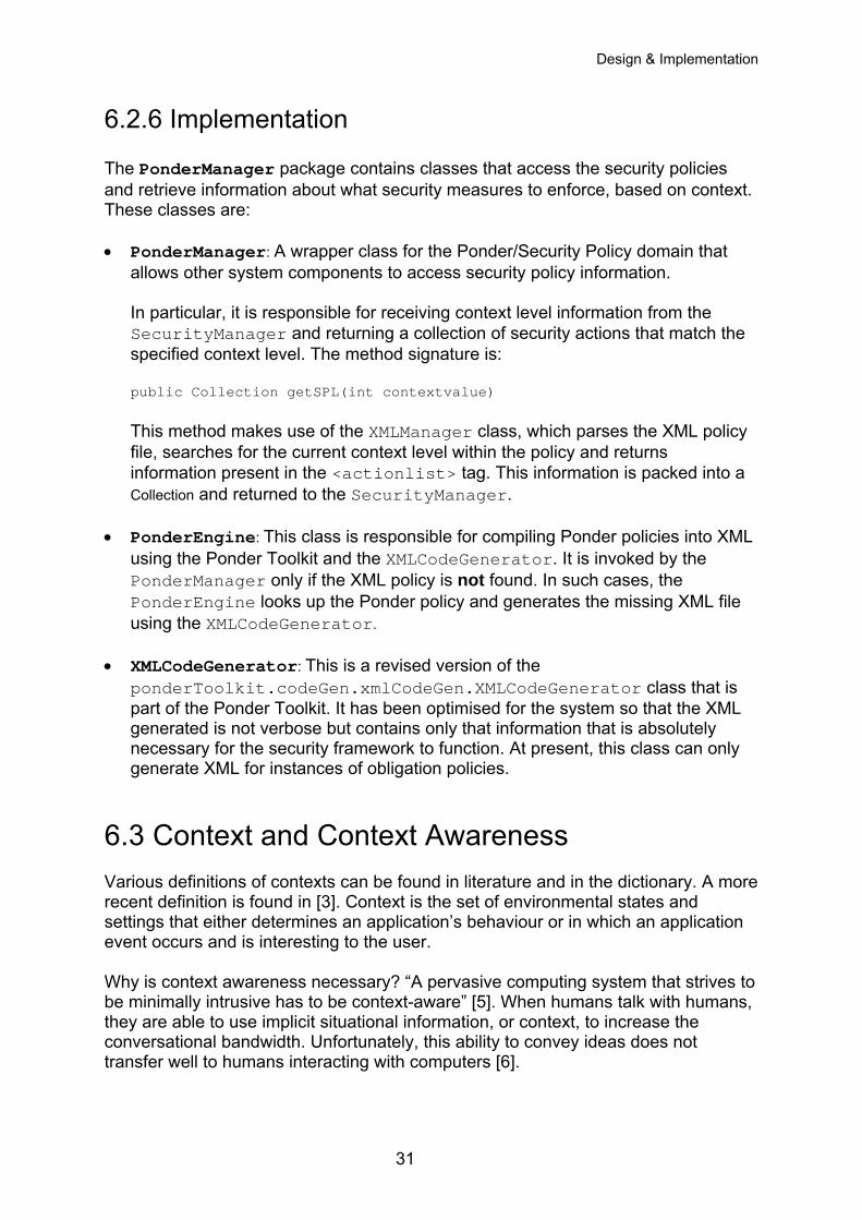
Design & Implementation
6.2.6 Implementation The PonderManager package contains classes that access the security policies and retrieve information about what security measures to enforce, based on context. These classes are: • PonderManager: A wrapper class for the Ponder/Security Policy domain that
allows other system components to access security policy information. In particular, it is responsible for receiving context level information from the SecurityManager and returning a collection of security actions that match the specified context level. The method signature is: public Collection getSPL(int contextvalue) This method makes use of the XMLManager class, which parses the XML policy file, searches for the current context level within the policy and returns information present in the <actionlist> tag. This information is packed into a Collection and returned to the SecurityManager.
• PonderEngine: This class is responsible for compiling Ponder policies into XML using the Ponder Toolkit and the XMLCodeGenerator. It is invoked by the PonderManager only if the XML policy is not found. In such cases, the PonderEngine looks up the Ponder policy and generates the missing XML file using the XMLCodeGenerator.
• XMLCodeGenerator: This is a revised version of the ponderToolkit.codeGen.xmlCodeGen.XMLCodeGenerator class that is part of the Ponder Toolkit. It has been optimised for the system so that the XML generated is not verbose but contains only that information that is absolutely necessary for the security framework to function. At present, this class can only generate XML for instances of obligation policies.
6.3 Context and Context Awareness Various definitions of contexts can be found in literature and in the dictionary. A more recent definition is found in [3]. Context is the set of environmental states and settings that either determines an application’s behaviour or in which an application event occurs and is interesting to the user. Why is context awareness necessary? “A pervasive computing system that strives to be minimally intrusive has to be context-aware” [5]. When humans talk with humans, they are able to use implicit situational information, or context, to increase the conversational bandwidth. Unfortunately, this ability to convey ideas does not transfer well to humans interacting with computers [6].
31
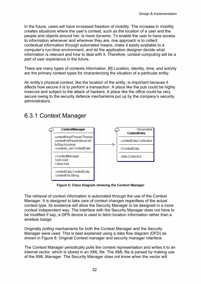
Design & Implementation
In the future, users will have increased freedom of mobility. The increase in mobility creates situations where the user’s context, such as the location of a user and the people and objects around her, is more dynamic. To enable the user to have access to information whenever and wherever they are, one approach is to collect contextual information through automated means, make it easily available to a computer’s run-time environment, and let the application designer decide what information is relevant and how to deal with it. Therefore, context computing will be a part of user experience in the future. There are many types of contexts information. [6] Location, identity, time, and activity are the primary context types for characterizing the situation of a particular entity. An entity’s physical context, like the location of the entity, is important because it affects how secure it is to perform a transaction. A place like the pub could be highly insecure and subject to the attack of hackers. A place like the office could be very secure owing to the security defence mechanisms put up by the company’s security administrators.
6.3.1 Context Manager
Figure 5: Class Diagram showing the Context Manager
The retrieval of context information is automated through the use of the Context Manager. It is designed to take care of context changes regardless of the actual context type. Its existence will allow the Security Manager to be designed in a more context independent way. The interface with the Security Manager does not have to be modified if say, a GPS device is used to fetch location information rather than a wireless badge. Originally polling mechanisms for both the Context Manager and the Security Manager were used. This is best explained using a data flow diagram (DFD) as shown in Figure 6: Original Context manager and security manager interface. The Context Manager periodically polls the context representation and writes it to an internal vector, which is stored in an XML file. The XML file is parsed by making use of the XML Manager. The Security Manager does not know when the vector will
32
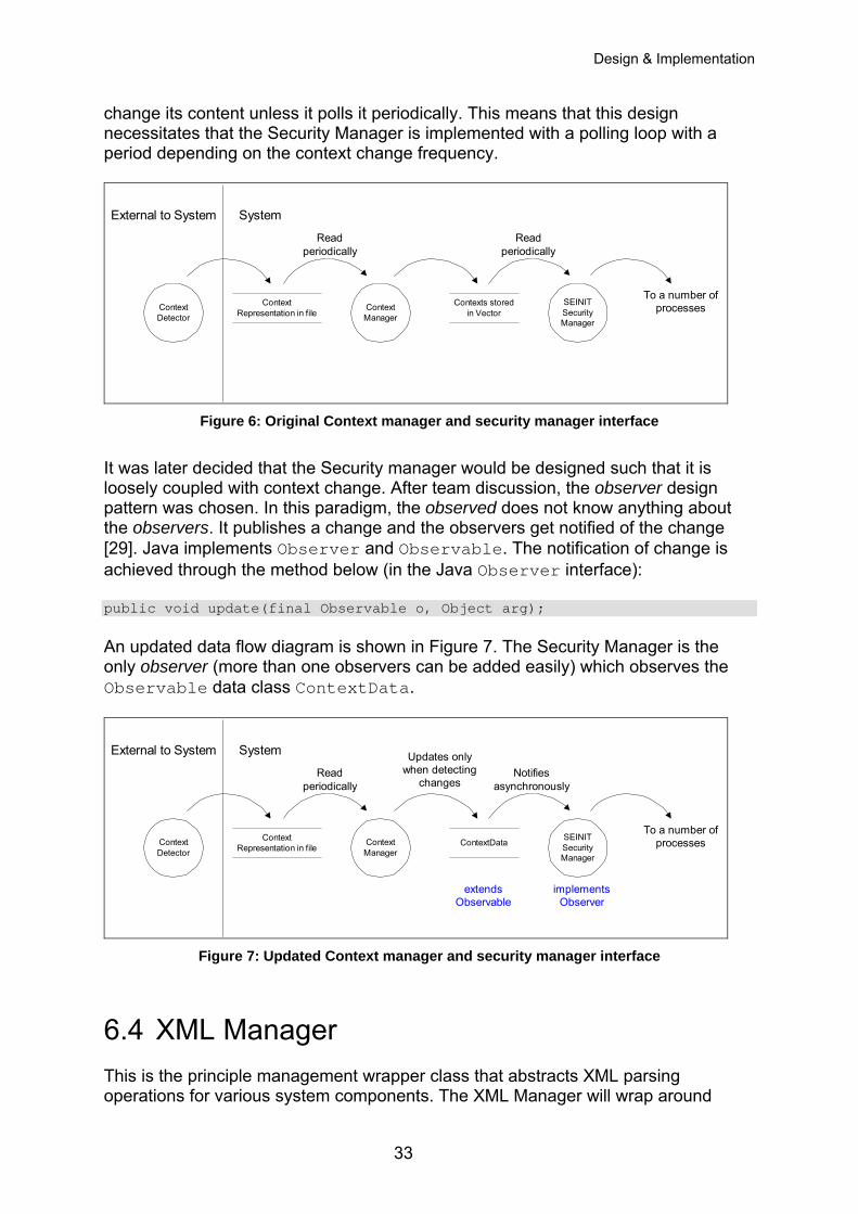
Design & Implementation
change its content unless it polls it periodically. This means that this design necessitates that the Security Manager is implemented with a polling loop with a period depending on the context change frequency.
ContextRepresentation in file
ContextManager
Contexts storedin Vector
ContextDetector
SEINITSecurityManager
External to System System
Readperiodically
Readperiodically
To a number ofprocesses
Figure 6: Original Context manager and security manager interface
It was later decided that the Security manager would be designed such that it is loosely coupled with context change. After team discussion, the observer design pattern was chosen. In this paradigm, the observed does not know anything about the observers. It publishes a change and the observers get notified of the change [29]. Java implements Observer and Observable. The notification of change is achieved through the method below (in the Java Observer interface): public void update(final Observable o, Object arg); An updated data flow diagram is shown in Figure 7. The Security Manager is the only observer (more than one observers can be added easily) which observes the Observable data class ContextData.
ContextRepresentation in file
ContextManager
ContextDataContextDetector
SEINITSecurityManager
External to System System
Readperiodically
Notifiesasynchronously
To a number ofprocesses
implementsObserver
Updates onlywhen detecting
changes
extendsObservable
Figure 7: Updated Context manager and security manager interface
6.4 XML Manager This is the principle management wrapper class that abstracts XML parsing operations for various system components. The XML Manager will wrap around
33
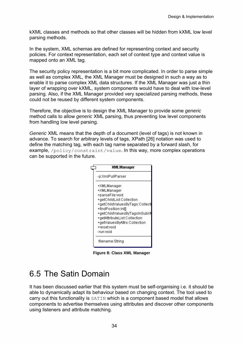
Design & Implementation
kXML classes and methods so that other classes will be hidden from kXML low level parsing methods. In the system, XML schemas are defined for representing context and security policies. For context representation, each set of context type and context value is mapped onto an XML tag. The security policy representation is a bit more complicated. In order to parse simple as well as complex XML, the XML Manager must be designed in such a way as to enable it to parse complex XML data structures. If the XML Manager was just a thin layer of wrapping over kXML, system components would have to deal with low-level parsing. Also, if the XML Manager provided very specialized parsing methods, these could not be reused by different system components. Therefore, the objective is to design the XML Manager to provide some generic method calls to allow generic XML parsing, thus preventing low level components from handling low level parsing. Generic XML means that the depth of a document (level of tags) is not known in advance. To search for arbitrary levels of tags, XPath [26] notation was used to define the matching tag, with each tag name separated by a forward slash, for example, /policy/constraint/value. In this way, more complex operations can be supported in the future.
Figure 8: Class XML Manager
6.5 The Satin Domain It has been discussed earlier that this system must be self-organising i.e. it should be able to dynamically adapt its behaviour based on changing context. The tool used to carry out this functionality is SATIN which is a component based model that allows components to advertise themselves using attributes and discover other components using listeners and attribute matching.
34
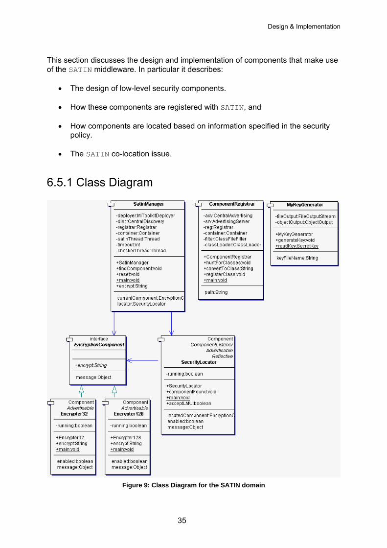
Design & Implementation
This section discusses the design and implementation of components that make use of the SATIN middleware. In particular it describes:
• The design of low-level security components.
• How these components are registered with SATIN, and
• How components are located based on information specified in the security policy.
• The SATIN co-location issue.
6.5.1 Class Diagram
Figure 9: Class Diagram for the SATIN domain
35
Design & Implementation
6.5.1 Designing Low-level Security Components A low-level security component is responsible solely for carrying out some form of security. For example, a low-level encryption component simply defines an encryption scheme. There may be different kinds of low-level encryption components, each defining their own encryption scheme, such as DES, AES or Blowfish. A system may have many low-level security components. This security framework must be able to dynamically load the appropriate component based on context information. SATIN is suitable for this task, since it provides an advertising and discovery service and allows a system to re-organise itself. It was decided to start off by designing and implementing low-level encryption components. Later on, the system could be extended by having low-level security components that implement authentication, for instance.
6.5.2 The Encryption Interface Since all encryption components must implement an encryption scheme a common interface called EncryptionComponent was designed which contains the single method: public String encrypt(String data) throws Exception; This method is responsible for encrypting the specified string of data. Having the interface makes the system extensible, because in the future more encryption components can be developed provided they implement this interface.
6.5.3 Key Generation In general, encryption schemes require a key. As mentioned in the assumptions, key management is out of the scope of this project. Nevertheless, keys are required to test the encryption schemes and hence the overall system. It was decided to devise a key generator, which would generate a key and write this key to a file. The low-level encryption components would then read this key from the file and use it in the encryption process. The reason for choosing this method is that the key generator can be removed if PKI or key management exists on the device already. This is implemented in the MyKeyGenerator class which works like this: KeyGenerator kg = KeyGenerator.getInstance(“DES”); kg.init(new SecureRandom());
36
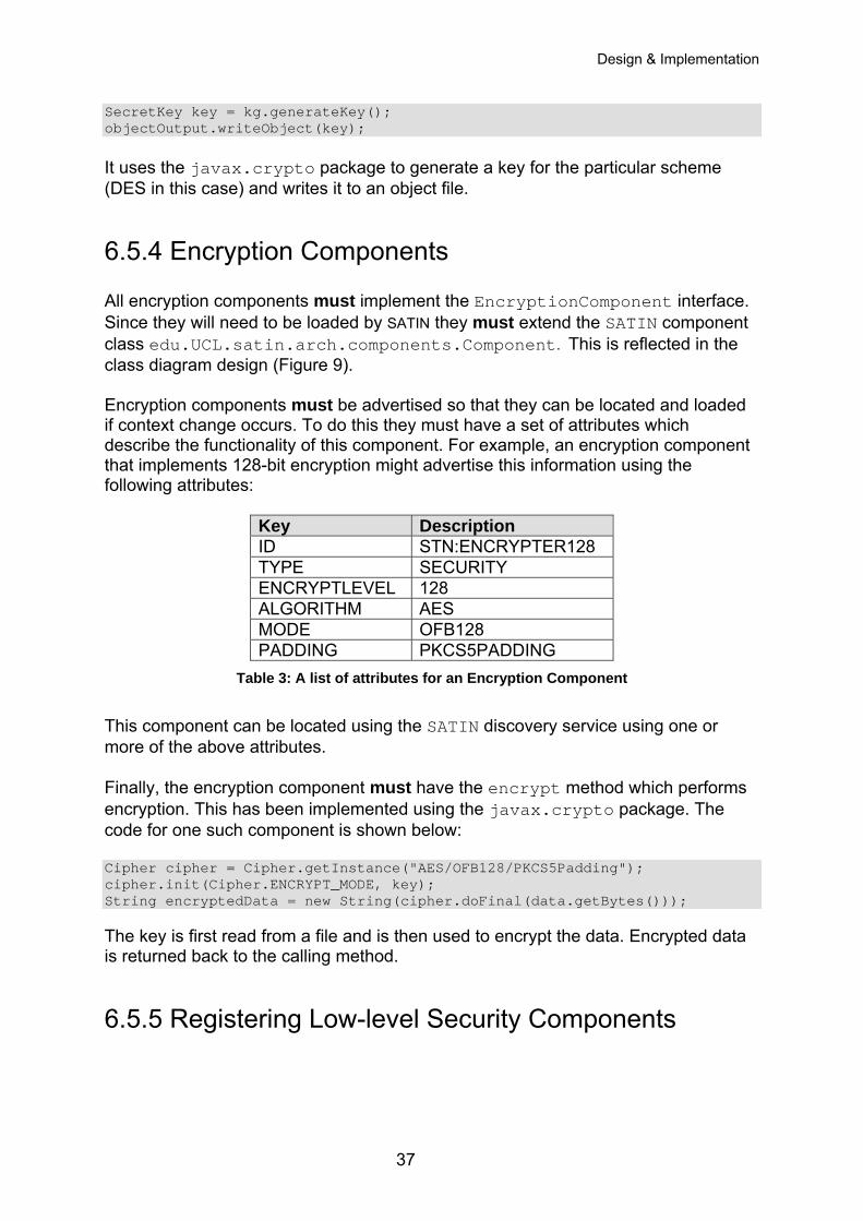
Design & Implementation
SecretKey key = kg.generateKey(); objectOutput.writeObject(key); It uses the javax.crypto package to generate a key for the particular scheme (DES in this case) and writes it to an object file.
6.5.4 Encryption Components All encryption components must implement the EncryptionComponent interface. Since they will need to be loaded by SATIN they must extend the SATIN component class edu.UCL.satin.arch.components.Component. This is reflected in the class diagram design (Figure 9). Encryption components must be advertised so that they can be located and loaded if context change occurs. To do this they must have a set of attributes which describe the functionality of this component. For example, an encryption component that implements 128-bit encryption might advertise this information using the following attributes:
Key Description ID STN:ENCRYPTER128 TYPE SECURITY ENCRYPTLEVEL 128 ALGORITHM AES MODE OFB128 PADDING PKCS5PADDING
Table 3: A list of attributes for an Encryption Component
This component can be located using the SATIN discovery service using one or more of the above attributes. Finally, the encryption component must have the encrypt method which performs encryption. This has been implemented using the javax.crypto package. The code for one such component is shown below: Cipher cipher = Cipher.getInstance("AES/OFB128/PKCS5Padding"); cipher.init(Cipher.ENCRYPT_MODE, key); String encryptedData = new String(cipher.doFinal(data.getBytes())); The key is first read from a file and is then used to encrypt the data. Encrypted data is returned back to the calling method.
6.5.5 Registering Low-level Security Components
37
Design & Implementation
After designing low-level security components that can be advertised, the next step is to register these components with the SATIN container. This is carried out by the container’s registrar using the registerComponent method. This method would have to be called for each component that has to be registered and is certainly not very flexible if the components to be registered changes in the future. Therefore, to make the registering process more efficient and scalable, it was decided to design a helper class which would automatically look for all “SATIN-compliant” components in a specified path, called the componentpath, and register them. (This is similar to the classpath variable in Java which lists class libraries.) An example of the componentpath could be “home/project:home/components”. Multiple paths are separated using the path delimiter which is ‘:’ for UNIX and ‘;’ for Windows Operating Systems. The helper class, called ComponentRegistrar, looks in the directories specified in the componentpath, hunts for classes that are SATIN-compliant, i.e. those that extend edu.UCL.satin.arch.components.Component, using the Java Reflection API and finally registers them. They can now be dynamically loaded if required.
6.5.6 Dynamically Loading Low-level Security Components SATIN components are located using the discovery service. A discovery component is required that registers listeners with the discovery service, to be notified when a specific component becomes available. Matching is done using a set of attributes provided by the discovery component. The discovery component designed is called SecurityLocator which registers itself with the discovery service as well as with the SATIN container. It is notified by the discovery service whenever a security component is located, via the method: public synchronized void componentFound(Component c) {} When this method is called, the locator verifies using Reflection that this component is indeed a security component. If it implements the EncryptionComponent interface, it is an encryption component and is hence capable of encrypting data. The component is then loaded and passed to the SatinManager.
6.5.7 The SATIN Manager
38
Design & Implementation
The SATIN Manager oversees everything that goes on within the SATIN domain. All other components of the system that wish to use the SATIN middleware to locate components must go through the manager. The SATIN Manager is primarily responsible for liaising with the Security Manager in order to load components matching a set of attributes. The crucial method is: public void findComponent(final Collection securityPolicyLevel) {} It is provided with a set of attributes that the desired security component must have. For example, the set might be, [[TYPE, SECURITY], [ENCRYPTLEVEL, 128]].The attributes are then added to a “SATIN filter” which defines the criteria used for searching (e.g. exact matching). The manager then searches the SATIN container, using the SecurityLocator, for a component that matches this set of attributes. If it is found, the component is loaded and its security measures are enforced. The system is then said to be in a secure state. When context change takes place, the system is insecure until the SATIN Manager can find a security component that matches the set of desired attributes for the new context.
6.5.8 The SATIN Co-Location Issue The advertising and discovery services of the SATIN middleware have to be run of different hosts for everything to work normally. In our case, this would mean having to run the SATIN middleware on a remote host, which would advertise a low-level encryption component, for example. The discovery service of the SATIN middleware would then have to be run on another host. This would result in components being located and loaded successfully. If, however, both services are run on the same host SATIN is unable to locate and load components. This is referred to as the SATIN co-location issue. The need for SATIN co-location arises from the policy level need for end-point as opposed to application security. As mentioned before, the aim is to make the device itself secure, rather than securing applications individually. The assumption is that only applications running on the device can access the system. This means that if SATIN itself is on another device, the security manager will end up communicating with it via plain text over a network at least some of the time during the system flow. Any plain text communication over a network violates the goal of end-point security as such communication is vulnerable to security attack. Therefore, it is essential to ensure that SATIN it self is running on the same host as the rest of the system. The Solution
39
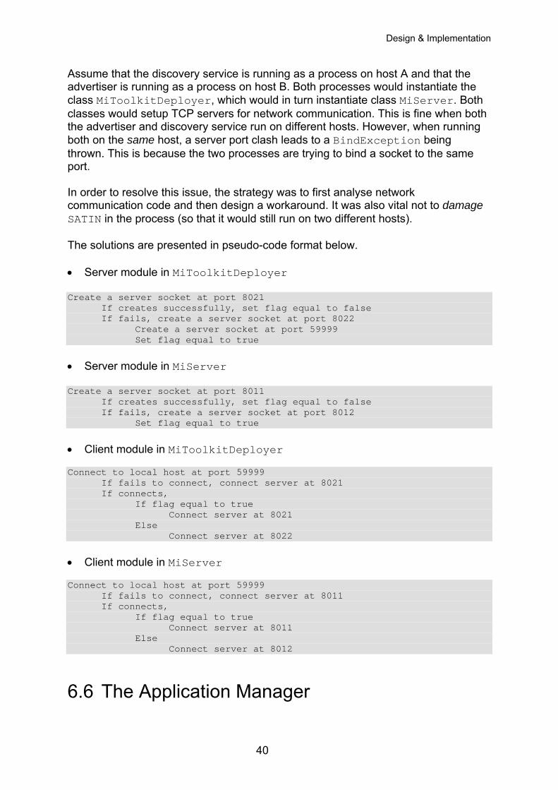
Design & Implementation
Assume that the discovery service is running as a process on host A and that the advertiser is running as a process on host B. Both processes would instantiate the class MiToolkitDeployer, which would in turn instantiate class MiServer. Both classes would setup TCP servers for network communication. This is fine when both the advertiser and discovery service run on different hosts. However, when running both on the same host, a server port clash leads to a BindException being thrown. This is because the two processes are trying to bind a socket to the same port. In order to resolve this issue, the strategy was to first analyse network communication code and then design a workaround. It was also vital not to damage SATIN in the process (so that it would still run on two different hosts). The solutions are presented in pseudo-code format below. • Server module in MiToolkitDeployer
Create a server socket at port 8021 If creates successfully, set flag equal to false
If fails, create a server socket at port 8022 Create a server socket at port 59999
Set flag equal to true • Server module in MiServer Create a server socket at port 8011 If creates successfully, set flag equal to false
If fails, create a server socket at port 8012 Set flag equal to true • Client module in MiToolkitDeployer Connect to local host at port 59999 If fails to connect, connect server at 8021 If connects, If flag equal to true Connect server at 8021 Else Connect server at 8022 • Client module in MiServer Connect to local host at port 59999 If fails to connect, connect server at 8011 If connects, If flag equal to true Connect server at 8011 Else Connect server at 8012
6.6 The Application Manager
40
Design & Implementation
The Application Manager is the only point of contact for the any entity external to the system. It acts as the interface for the system.
6.6.1 Functioning The Application Manager reads in a text file from the system and then parses it to retrieve the latest set of SEINIT well-known ports. This gives the system the flexibility of always knowing the latest port numbers. It then starts a thread listening to each of the ports specified (the maximum is 9). As soon as it senses data on the port, it captures it and sends it to the Security Manager. This is a blocking call. When the call returns, the Application Manager sends the now encrypted data back to the application at the IP/port it received it from, thus closing the loop.
6.6.2 Modes The Application Manager works in two modes; local and multicast. In the local mode it only listens to the local host of the device. The local host IP is retrieved dynamically, making the system inherently portable without code change. In the multicast mode, it listens to the Well-known SEINIT Multicast IP (239.255.255.0) as well as the local host. The Application Manager is multi-threaded in both local and multicast modes.
6.6.3 The Demo Application The demo application developed to demonstrate the system is a simple chat application named ChatInterface. This application can work in either local or multicast mode. It is foolproof, i.e. in the event that it is started in multicast mode when the cable is not connected or the network is not multicast enabled, it will automatically detect that and multicast to the local host instead. The multicast mode enables the application to be either co-located on the SEINIT host or be on a network and talk to any listening SEINIT host on that network via multicast. In local mode, it auto detects the local host settings. The user types in text into a chat window which is then sent by the application to the SEINIT well-known port for chat applications 9010. It then blocks waiting for data to be returned. When it senses return data at this port, it publishes it to the chat window. This demonstrates the complete information flow.
6.7 The Audit Tool
41
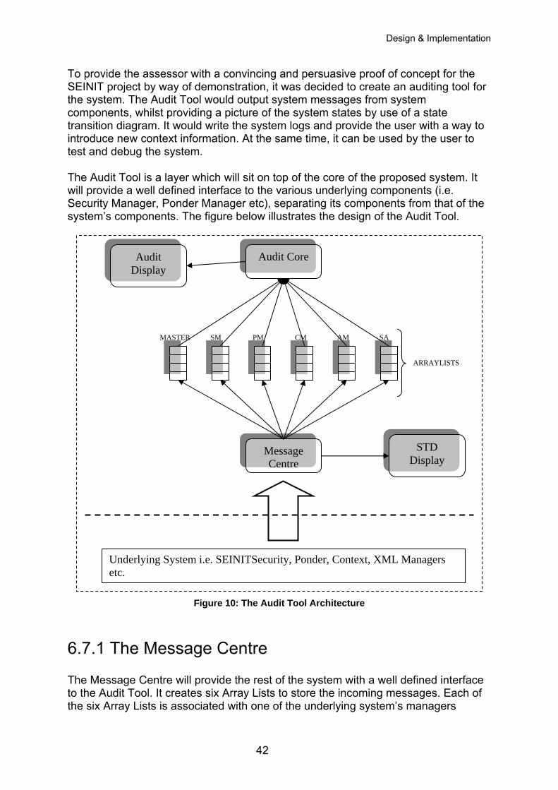
Design & Implementation
To provide the assessor with a convincing and persuasive proof of concept for the SEINIT project by way of demonstration, it was decided to create an auditing tool for the system. The Audit Tool would output system messages from system components, whilst providing a picture of the system states by use of a state transition diagram. It would write the system logs and provide the user with a way to introduce new context information. At the same time, it can be used by the user to test and debug the system. The Audit Tool is a layer which will sit on top of the core of the proposed system. It will provide a well defined interface to the various underlying components (i.e. Security Manager, Ponder Manager etc), separating its components from that of the system’s components. The figure below illustrates the design of the Audit Tool.
Audit Core Audit Display
Figure 10: The Audit Tool Architecture
6.7.1 The Message Centre The Message Centre will provide the rest of the system with a well defined interface to the Audit Tool. It creates six Array Lists to store the incoming messages. Each of the six Array Lists is associated with one of the underlying system’s managers
PM SM SA AM CM MASTER
STD Display
Message Centre
ARRAYLISTS
Underlying System i.e. SEINITSecurity, Ponder, Context, XML Managers etc.
42
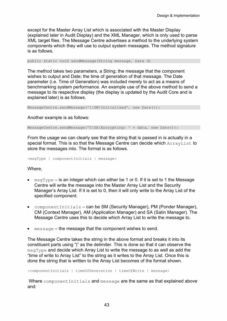
Design & Implementation
except for the Master Array List which is associated with the Master Display (explained later in Audit Display) and the XML Manager, which is only used to parse XML target files. The Message Centre advertises a method to the underlying system components which they will use to output system messages. The method signature is as follows. public static void sendMessage(String message, Date d) The method takes two parameters, a String; the message that the component wishes to output and Date; the time of generation of that message. The Date parameter (i.e. Time of Generation) was included merely to act as a means of benchmarking system performance. An example use of the above method to send a message to its respective display (the display is updated by the Audit Core and is explained later) is as follows. MessageCentre.sendMessage("1|SM|Initialised", new Date()); Another example is as follows: MessageCentre.sendMessage("0|SA|Encrypting: " + data, new Date()); From the usage we can clearly see that the string that is passed in is actually in a special format. This is so that the Message Centre can decide which ArrayList to store the messages into. The format is as follows. <msgType | componentInitials | message> Where, • msgType – is an integer which can either be 1 or 0. If it is set to 1 the Message
Centre will write the message into the Master Array List and the Security Manager’s Array List. If it is set to 0, then it will only write to the Array List of the specified component.
• componentInitials – can be SM (Security Manager), PM (Ponder Manager), CM (Context Manager), AM (Application Manager) and SA (Satin Manager). The Message Centre uses this to decide which Array List to write the message to.
• message – the message that the component wishes to send. The Message Centre takes the string in the above format and breaks it into its constituent parts using “|” as the delimiter. This is done so that it can observe the msgType and decide which Array List to write the message to as well as add the “time of write to Array List” to the string as it writes to the Array List. Once this is done the string that is written to the Array List becomes of the format shown. <componentInitials | timeOfGeneration | timeOfWrite | message> Where componentInitials and message are the same as that explained above and:
43
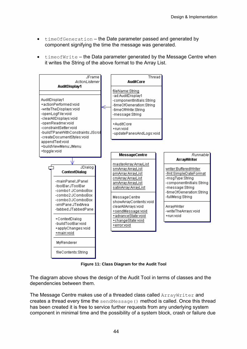
Design & Implementation
• timeOfGeneration – the Date parameter passed and generated by
component signifying the time the message was generated.
• timeofWrite – the Data parameter generated by the Message Centre when it writes the String of the above format to the Array List.
Figure 11: Class Diagram for the Audit Tool
The diagram above shows the design of the Audit Tool in terms of classes and the dependencies between them. The Message Centre makes use of a threaded class called ArrayWriter and creates a thread every time the sendMessage() method is called. Once this thread has been created it is free to service further requests from any underlying system component in minimal time and the possibility of a system block, crash or failure due
44
Design & Implementation
to multiple asynchronous requests is reduced. It is understood that the occurring system processes are sequential and asynchronous system output requests is unlikely, however to facilitate related future enhancements to the system and add to the scalability of the system, it was decided that the Message Centre must be able to service asynchronous requests. Thus the Message Centre will be written such that is threaded. The created thread will then, on behalf of the Message Centre handle the breakdown of the message and write to the Array List, for that particular message. Since the system uses threads, the incorporation of time of generation, time of write to Array List and time of write to Display (this time value is added to the message by the Audit Display and is explained later) gave the developers a feel for the performance of the system. Each spawned thread completes the write to the display at a different time. These time value outputs also provided an ideal way to observe the threading in the system and also help the developers in debugging the Audit Tool. When deciding on a data structure to store the incoming messages, tuple spaces and Vectors were also considered. However ArrayLists were chosen as they are slightly faster than Vectors and do not need to be synchronized whilst in a multithreaded environment. Vectors do not allow for this and incur further synchronization overhead. Tuple spaces are essentially hash tables (i.e. key – value pairs) and to top it off they make use of Vectors incurring further system resource usage. Even though Tuple spaces provide for a powerful data structure with quick look up, it was dismissed on the grounds of its complexity. For the purpose of the Audit Tool the data that needed to be stored is of a simple structure while Tuple spaces are more suited towards the storage of more complex data. Also since only a single element lookup at position zero (explained in Audit Core) is done, the fast lookup times of Tuple Spaces are not of importance. The ArrayWriter is also responsible for creating and updating a user specified log file for a particular session. Every time a message comes in, the ArrayWriter breaks down the message into its constituent parts, adds a time write String to the whole and writes the line of text to the specified log file, which is of the following format. <msgType | componentInitials | timeOfGeration | timeOfWrite | message> Earlier it was stated that six Array Lists were created, one for each Managerial component and one for higher level system messages i.e. Master Array List. This decision was made on the basis that if a single Array List were used to store all messages, then this would create a bottleneck in the system and potentially crash the system. Another reason is that since the Array List will be accessed by multiple threads, preserving the order of the messages will not be possible as different threads will complete at different times. This would incur further overhead in the form of a complex sorting algorithm which will have to sort each Array List using the time of generation as the sorting criteria. This is because the Audit Tool must be able to display message 1 generated at time 2 before message 2 generated at time 3 even if message 2 is written into the Array List before message 1. For arguments sake lets assume we have a sorting algorithm which will sort the Array Lists, but then how can it be decided when to actually execute the sort. How can it be known that thread
45
Design & Implementation
number 1 has completed execution and is not blocked? If thread one is blocked and we run the sort algorithm and update the Displays, we are bound to have incorrectly ordered system messages on the screen once thread number 1 does complete. Thus by creating an Array List for each of the system components and connecting them we have reduced the possibility of “blocked” or “waiting” threads.
6.7.2 Audit Core As shown in the architectural diagram the Audit Core component sits just on top of the Message Centre. The Audit Core is at the centre of the Audit Tool and is started up by the Security Manager explained earlier. Once started the Audit Core starts up the Audit Display which provides the user with the interface required to interact with the system. From the architectural diagram we can see that the Array Lists separate the Message Centre from the Audit Core. This approach allows for a decoupled system that can then stand on its own. The Array Lists also provide crucial buffering to the Audit Core and help in preserving the correct order in which messages should be displayed, since some threads may complete quicker than others. This is important as the Audit Core essentially polls each Array List in an infinite “while” loop during which a write can also occur to the Array List. This further solidifies the team’s reasons for using Array Lists as the data structure of choice as they are industrially favoured in environments where continuous iteration of data is required in a multithreaded environment. As stated earlier the Audit Core polls each Array Lists to check if it’s empty. If the Array List does contain data then it invokes the implemented update method with the following signature. private void updatePanesAndLogs(JTextPane pane, AuditDisplay1 ad, ArrayList list) The method has three parameters, a JTextPane; which specifies which display to write the message to, an AuditDisplay1; so as to be able to call the appendText() method and an ArrayList; which specifies the Array List from which the data will be fetched. The updatePanesAndLogs() method works by breaking down the message after fetching it from the respective Array List. Once this is done it creates and initialises an array of String objects with the message constituents and calls the appendText() method (explained in Audit Display) passing it the array of String objects and the respective pane. Finally it removes the fetched message from the Array List. So the next time around the loop the element which used to be at position one and has now moved to the new position of zero, will be fetched. A single fetch at position zero is always done since the size of an Array List will keep fluctuating. This fluctuation is due to the concurrent writes (by Message Centre) and removes (by Audit Core) to an Array List.
6.7.3 Audit Display The generated message display areas are as follows.
46
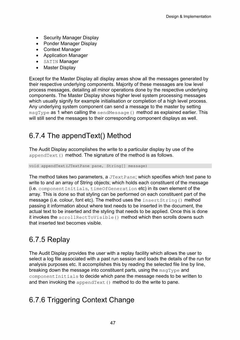
Design & Implementation
• Security Manager Display • Ponder Manager Display • Context Manager • Application Manager • SATIN Manager • Master Display
Except for the Master Display all display areas show all the messages generated by their respective underlying components. Majority of these messages are low level process messages, detailing all minor operations done by the respective underlying components. The Master Display shows higher level system processing messages which usually signify for example initialisation or completion of a high level process. Any underlying system component can send a message to the master by setting msgType as 1 when calling the sendMessage() method as explained earlier. This will still send the messages to their corresponding component displays as well.
6.7.4 The appendText() Method The Audit Display accomplishes the write to a particular display by use of the appendText() method. The signature of the method is as follows. void appendText(JTextPane pane, String[] message) The method takes two parameters, a JTextPane; which specifies which text pane to write to and an array of String objects; which holds each constituent of the message (i.e. componentInitials, timeOfGeneration etc) in its own element of the array. This is done so that styling can be performed on each constituent part of the message (i.e. colour, font etc). The method uses the insertString() method passing it information about where text needs to be inserted in the document, the actual text to be inserted and the styling that needs to be applied. Once this is done it invokes the scrollRectToVisible() method which then scrolls downs such that inserted text becomes visible.
6.7.5 Replay The Audit Display provides the user with a replay facility which allows the user to select a log file associated with a past run session and loads the details of the run for analysis purposes etc. It accomplishes this by reading the selected file line by line, breaking down the message into constituent parts, using the msgType and componentInitials to decide which pane the message needs to be written to and then invoking the appendText() method to do the write to pane.
6.7.6 Triggering Context Change
47
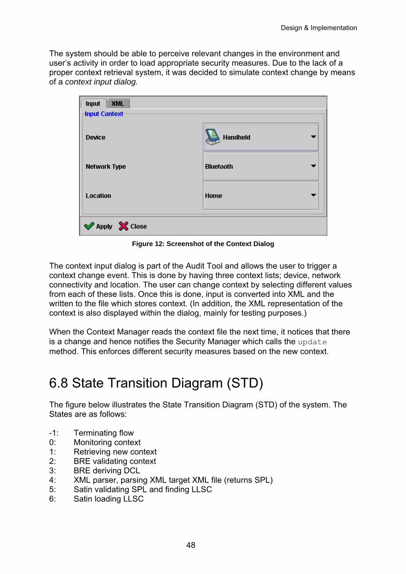
Design & Implementation
The system should be able to perceive relevant changes in the environment and user’s activity in order to load appropriate security measures. Due to the lack of a proper context retrieval system, it was decided to simulate context change by means of a context input dialog.
Figure 12: Screenshot of the Context Dialog
The context input dialog is part of the Audit Tool and allows the user to trigger a context change event. This is done by having three context lists; device, network connectivity and location. The user can change context by selecting different values from each of these lists. Once this is done, input is converted into XML and the written to the file which stores context. (In addition, the XML representation of the context is also displayed within the dialog, mainly for testing purposes.) When the Context Manager reads the context file the next time, it notices that there is a change and hence notifies the Security Manager which calls the update method. This enforces different security measures based on the new context.
6.8 State Transition Diagram (STD) The figure below illustrates the State Transition Diagram (STD) of the system. The States are as follows: -1: Terminating flow 0: Monitoring context 1: Retrieving new context 2: BRE validating context 3: BRE deriving DCL 4: XML parser, parsing XML target XML file (returns SPL) 5: Satin validating SPL and finding LLSC 6: Satin loading LLSC
48
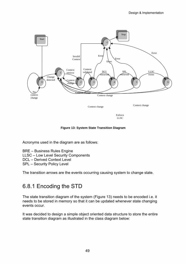
Design & Implementation
Stop
-1
Figure 13: System State Transition Diagram
Acronyms used in the diagram are as follows: BRE – Business Rules Engine LLSC – Low Level Security Components DCL – Derived Context Level SPL – Security Policy Level The transition arrows are the events occurring causing system to change state.
6.8.1 Encoding the STD The state transition diagram of the system (Figure 13) needs to be encoded i.e. it needs to be stored in memory so that it can be updated whenever state changing events occur. It was decided to design a simple object oriented data structure to store the entire state transition diagram as illustrated in the class diagram below:
Context validated DCL
retrieved SPL
retrieved
Error
Error Error
Context change
Context change
Context change
Context change
Context change
Enforce LLSC
LLSC exists
Error Invalid Context
Context retrieve
No context change
Change detected
0 3 2 4 5 6
1
Start
49
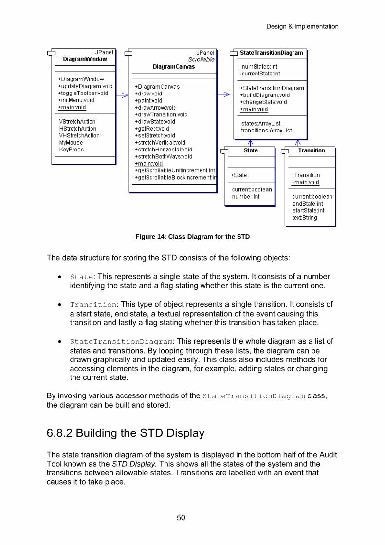
Design & Implementation
Figure 14: Class Diagram for the STD
The data structure for storing the STD consists of the following objects:
• State: This represents a single state of the system. It consists of a number identifying the state and a flag stating whether this state is the current one.
• Transition: This type of object represents a single transition. It consists of a start state, end state, a textual representation of the event causing this transition and lastly a flag stating whether this transition has taken place.
• StateTransitionDiagram: This represents the whole diagram as a list of states and transitions. By looping through these lists, the diagram can be drawn graphically and updated easily. This class also includes methods for accessing elements in the diagram, for example, adding states or changing the current state.
By invoking various accessor methods of the StateTransitionDiagram class, the diagram can be built and stored.
6.8.2 Building the STD Display The state transition diagram of the system is displayed in the bottom half of the Audit Tool known as the STD Display. This shows all the states of the system and the transitions between allowable states. Transitions are labelled with an event that causes it to take place.
50
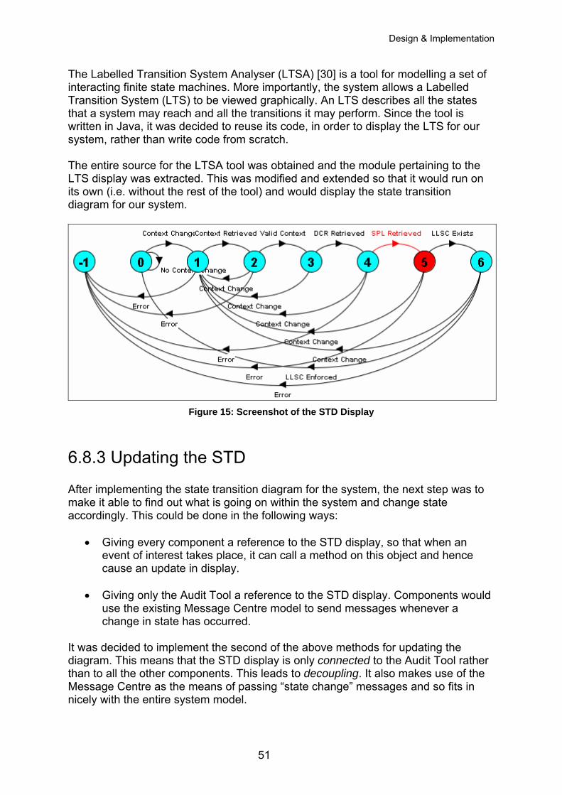
Design & Implementation
The Labelled Transition System Analyser (LTSA) [30] is a tool for modelling a set of interacting finite state machines. More importantly, the system allows a Labelled Transition System (LTS) to be viewed graphically. An LTS describes all the states that a system may reach and all the transitions it may perform. Since the tool is written in Java, it was decided to reuse its code, in order to display the LTS for our system, rather than write code from scratch. The entire source for the LTSA tool was obtained and the module pertaining to the LTS display was extracted. This was modified and extended so that it would run on its own (i.e. without the rest of the tool) and would display the state transition diagram for our system.
Figure 15: Screenshot of the STD Display
6.8.3 Updating the STD After implementing the state transition diagram for the system, the next step was to make it able to find out what is going on within the system and change state accordingly. This could be done in the following ways:
• Giving every component a reference to the STD display, so that when an event of interest takes place, it can call a method on this object and hence cause an update in display.
• Giving only the Audit Tool a reference to the STD display. Components would use the existing Message Centre model to send messages whenever a change in state has occurred.
It was decided to implement the second of the above methods for updating the diagram. This means that the STD display is only connected to the Audit Tool rather than to all the other components. This leads to decoupling. It also makes use of the Message Centre as the means of passing “state change” messages and so fits in nicely with the entire system model.
51
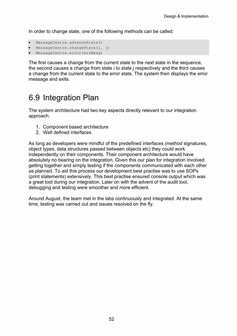
Design & Implementation
In order to change state, one of the following methods can be called: • MessageCentre.advanceState() • MessageCentre.changeState(i, j) • MessageCentre.error(errMesg) The first causes a change from the current state to the next state in the sequence, the second causes a change from state i to state j respectively and the third causes a change from the current state to the error state. The system then displays the error message and exits.
6.9 Integration Plan The system architecture had two key aspects directly relevant to our integration approach.
1. Component based architecture 2. Well defined interfaces
As long as developers were mindful of the predefined interfaces (method signatures, object types, data structures passed between objects etc) they could work independently on their components. Their component architecture would have absolutely no bearing on the integration. Given this our plan for integration involved getting together and simply testing if the components communicated with each other as planned. To aid this process our development best practise was to use SOPs (print statements) extensively. This best practise ensured console output which was a great tool during our integration. Later on with the advent of the audit tool, debugging and testing were smoother and more efficient. Around August, the team met in the labs continuously and integrated. At the same time, testing was carried out and issues resolved on the fly.
52
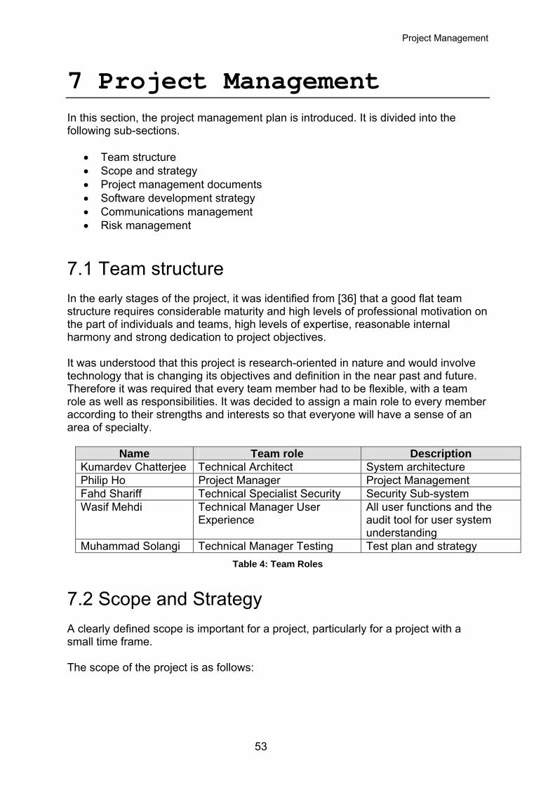
Project Management
7 Project Management In this section, the project management plan is introduced. It is divided into the following sub-sections.
• Team structure • Scope and strategy • Project management documents • Software development strategy • Communications management • Risk management
7.1 Team structure In the early stages of the project, it was identified from [36] that a good flat team structure requires considerable maturity and high levels of professional motivation on the part of individuals and teams, high levels of expertise, reasonable internal harmony and strong dedication to project objectives. It was understood that this project is research-oriented in nature and would involve technology that is changing its objectives and definition in the near past and future. Therefore it was required that every team member had to be flexible, with a team role as well as responsibilities. It was decided to assign a main role to every member according to their strengths and interests so that everyone will have a sense of an area of specialty.
Name Team role Description Kumardev Chatterjee Technical Architect System architecture Philip Ho Project Manager Project Management Fahd Shariff Technical Specialist Security Security Sub-system Wasif Mehdi Technical Manager User
Experience All user functions and the audit tool for user system understanding
Muhammad Solangi Technical Manager Testing Test plan and strategy Table 4: Team Roles
7.2 Scope and Strategy A clearly defined scope is important for a project, particularly for a project with a small time frame. The scope of the project is as follows:
53
Project Management
• Finding a way to define, map and implement security policies so that they can be reused.
• Finding and implementing a way to detect, map, retrieve and reuse context representation information.
• Finding a way to use context information and high level security policies to enforce security for the application as dynamically and with as little coupling as possible.
• Creating an extensible component based system that does the above.
• Creating a window into the system for a user to have a complete grasp of the workings of the system in real-time.
Initially it was planned to use several project management strategies to facilitate the project including the use of component-based architectures, the use of Unified Modelling Language (UML) to manage design complexity, managing of requirements by continually prioritized requirements and assessing progress. However, as is the nature of research projects this approach was changed. The system was designed iteratively. The system architecture diagram was used in preference to UML diagrams since the former has a lower management overhead. Progress was continually assessed by validating against requirements and scope iteratively, meeting by meeting with the stakeholders.
7.3 Project Management Documents Throughout the course of the project, several artefacts were generated to track and log the status of the project.
• A master schedule listing major milestones was maintained by the project manager (PM) using the Microsoft Project software.
• Meeting minutes were used to keep track of ideas, decisions and resolutions raised in meetings. These would give anyone who is unable to attend the meeting, a point of reference from which to work [37]. Meeting minutes were especially very useful when evaluating progress and writing this report!
• A communication tracker was used to keep track of all decisions and action items decided in meetings. Each action item was assigned to an owner and possibly a supporter(s).
Samples of some of the above mentioned documents can be found in the appendices.
54
Project Management
7.4 Software Development Strategy Working software products are important assets. Appropriate software tools are needed to create and maintain them. Eclipse [32], an open extensible, commercial-quality IDE was found which is very suitable for software development. It facilitated rapid software coding and debugging and provided JUnit [31] testing support. Since the project involved multiple developers, mechanisms were needed in order to ensure that one developer does not overwrite another’s work. Concurrent Versions Systems [32] was deployed in the first few weeks of software development. After experimenting with it for a few weeks, it was decided that its usage was not convenient in the present environment. Every time a team member needed to update the project code, the file would have to be checked out of the CVS server, downloaded through Secure Shell (SSH), and modified on their own computer. Then it would have to be uploaded and checked back in. This procedure was found to be rather error-prone. It was agreed unanimously that CVS is better used in a LAN environment rather than a WAN environment. Backups were used in order to avoid the loss of project work. Permanent storage media like CD-RW were used to store all code and project artefacts. Ideally two backups should have been created, stored in geographically distant locations to avoid theft or even regional catastrophe.
7.5 Communications Management The original plan was to meet two to three times per week. At least two team members preferred to work from home and so it was decided not to meet daily and also not require team members to be present at the university labs every day. Flexible meeting times were employed. The project supervisor, Dr. Steve Hailes, was met up with every week and the meeting time was agreed to on a per week basis. The agenda included but was not limited to report and evaluation of progress, gathering requirements and setting the next milestone. Meeting times were announced by the PM via a group wide email one to two days prior to the meeting after conferring with each team member.
7.5.1 The Website It was decided to set up a project website in order to facilitate the transfer of information and communication within the team. The website (http://www.cs.ucl.ac.uk/Students/z15_1) allowed members access to the meeting minutes, project calendar, important research links and other artefacts. The group shared directory was used to store source code and the CVS repository. Communication was carried out in a bidirectional way through emails and phones and in this way we progress and findings were reported, meetings scheduled and minutes distributed. The purpose of the website was to display:
55
Project Management
• Useful project information such as links to both external and internal
documents.
• Useful project management information such as links to meeting minutes and work tracking tools.
• The next meeting date, time and location so that members are fully aware of when the next meeting is.
• A long term calendar of the whole project duration (July to September) with important team events highlighted.
The website was implemented in pure HTML with some JavaScript for the calendar. Access Control Lists (ACLs) were used in order to make the website accessible by members of the team only.
7.6 Risk management Risk management is a very important process in a successful project. It involves risk identification, risk assessment and risk control processes. Dr. Steve Hailes was identified as the major stakeholder of the project who provided user requirements. Weekly discussions with him were held in order to seek his opinion to mitigate, if not remove, some of the risks. The other risks are classified as technical risk and human resources risk and are listed below.
7.6.1 Technical Risks The strategy employed to mitigate this kind of risk involved handling high priority and high risk items early. In the first few weeks, it was known that third-party software i.e. SATIN and Ponder were going to be incorporated. Since these are relatively new, it meant that there might not be enough support available. Troubleshooting would be required and in the worst case, modifying the source code of these technologies and platforms. The strategy was to test these technologies as early as possible and take necessary measures to rectify any subsequently identified problems. With hindsight, one of the highest risks that may have led the project to fail was to work on the PDA platform from the beginning. This risk was overcome by the realization that the major objective of the project is to prove a concept. To be able to run the system on a PDA would be good, however, it is not the most important goal. Therefore, right from iteration one, it was decided to develop and test our system on desktops. The result was that time was not spent on the learning cycle of PDA programming techniques and this greatly eased the software debugging efforts. The original plan was to start PDA platform development only after iteration two. After iteration one it was found that more features could be added to the desktop version in iteration two to make the POC more presentable and effective.
56
Project Management
The project scope clearly stated that development efforts were to be focused on building the system, not the applications. To demonstrate the concept, the original plan was to use a simple and ready-made application, like a text-based chat program. Only when there was time left in iteration two, our own application would be implemented. It demonstrated the feasibility of multiple applications using a single security framework.
7.6.2 Human Resources Risks Sometimes even though you try your best to identify risks, some risks just cannot be estimated. One of the team members injured his knee and urgently needed to go overseas to have it checked out in August. After assessing the risk, it was mitigated by reducing part of his testing workload and assigning a larger portion of the report writing task to him. Originally he was responsible for performing the integration test as well (this task requires much collaboration between team-mates) but that would have been difficult without his physical presence here. It had to be ensured that not a single task to be performed in that period would require his physical presence. Even so, continuous communication with him was maintained through e-mail and MSN chat. He finished building the application as well during this period which has been successfully incorporated into the system.
57
Demonstration of Concept & Testing
8 Demonstration of Concept & Testing The number of possible combinations to be tested could be excessively huge and associated labour can cost fortunes. It is the first thing to slip when resources stretch but it is the entire organization that suffers when a defect causes problems. A survey shows that a defect discovered during design that costs £1 to rectify will cost £1,000 to repair in production, not to mention the humiliation and embarrassment. This is a tremendous cost differential and clearly points out the advantage of early error detection. Significant resources in terms of man-hours were utilized to ensure that the system is bug-free.
8.1 White Box Testing (Structural Testing) For testing purpose, it was decided to use JUnit as much as possible. Our approach towards testing methods remained quiet flexible. It was mostly left to the discretion of the developer to decide whether to use JUnit or devise their own test cases. It was once again found most effective to use code inspection techniques or step-through the code using a debugger. SOPs (print statements) were also used in strategic parts of the code in order to identify possible problems. The Eclipse SDE was found quite useful in writing unit tests because of its integrated JUnit plug-in.
8.1.1 JUnit JUnit [31] is an open source Java testing framework used to write and run repeatable tests. It is an instance of the xUnit architecture for unit testing frameworks.
JUnit features include:
o Assertions for testing expected results o Test fixtures for sharing common test data o Test suites for easily organizing and running tests o Graphical and textual test runners
JUnit testing was carried out to rigorously test classes within the project. The example below shows how one such calls XMLManager was tested using the JUnit framework: • The test class is XMLManagerTest.
• XMLManagerTest does the following:
58
Demonstration of Concept & Testing
o The setup method initializes the XMLManager class with a pre-defined security policy in XML.
o The testPolicyCase1 method is used to assert the parsing operation on security policy in XML.
o Other methods are used to assert the other parsing operations defined in XMLManager.
Similarly, unit testing was carried out for other classes. It was tested whether each class behaved as expected under normal conditions, abnormal conditions and boundary conditions.
8.2 Black Box Testing (Functional Testing) While carrying out functional testing and commissioning, the Audit Tool and STD were found very useful. The following tests were carried out using these tools:
1. To verify that a valid change in context, triggers a change in SPL and results in a new low-level security component being enforced.
2. To verify that invalid context representation causes the system to fall into an error state and terminate as expected.
3. To verify that the low-level security components loaded are consistent with the information defined in the security policy.
4. To verify that all the combinations of context representation, derived context representation and security policy level respond as desired.
59
Future Work
9 Future work
9.1 Application and Security Manager: SEINIT Packet Format The application manager currently intercepts messages on the local host and SEINIT multicast IP for those messages that are sent explicitly to the SEINIT ports. The Application manager then sends back to the Application the encrypted messages. In the future, it should be possible for the Application Manager itself to do the ‘next hop’ step by passing the message to the next intended destination. This means that the message will have to be packed in to a SEINIT approved packet format that is generic and can be used by all applications intending to use the system. In the very least, this format will have three fields, the destination IP, the destination port and the message.
9.2 Component based software updates using SATIN Currently, the software is component based and each component can be independently updated of the others provided the interfaces are kept intact. However in the future, it should be possible to update them via SATIN. SATIN can independently locate all components on start-up and hence ensure that when the security manger is initialising, all components are the latest versions. This of-course mandates that SATIN becomes the first component to start up; therefore the information flow has to be altered.
9.3 Dynamic Business Rules Loading The business rules engine currently reads in the business rules statically via a fixed set of ‘case’ statements embedded in code. In the future this can be done dynamically, by reading in the rules on the fly from an XML file. This will ensure up to the minute dynamicity of the rules.
9.4 Incorporating User Preference Current context level is detected implicitly most of the time. However, the user should be allowed to override the current context setting by changing user preferences since user attention is most important in pervasive computing. The user may prefer to use highest security mechanism regardless of environment at the expense of more bandwidth utilization and high battery consumption.
60
Future Work
9.5 An Audit Trail It is necessary to implement security audit trails to enhance accountability. Audit trails can provide one of the strongest deterrents to abuse. Audit trails involve recording details of who, what and when an authorized access was made. Procedures are setup, to allow users to review to what extent his or her personal information is being published. Since this is an effective deterrent the team recommends future incorporation of an audit trail into the system.
9.6 Extending the XML Manager The XML Manager was designed keeping in mind the fact that this component would be used in many system sub-components. In the future, it is suggested incorporating XPath in the XML Manager implementation since it offers a very generic and extensible system.
9.7 Deployment and Testing More testing can be carried out on different handheld platforms including Microsoft Windows Mobile, Symbian OS and Palm OS. For Windows Mobile platform, emulators are available such as Microsoft Embedded Visual C++. For Palm OS testing, Palm OS Emulator [33] is available which has debugging features and is valuable for writing, testing and debugging applications by creating a “virtual” handhelds running on Windows, Mac OS, or UNIX computers. Before running emulators, a ROM image is usually required to load into the emulator. As of this writing, CDC has not yet been supported in Palm OS, probably due to the limited hardware capability in the current Palm hardware configurations. So in case Palm OS is used, porting of code to CLDC format is needed. After performing functionality testing on emulators, testing can be performed on real devices. By using real devices, performance metrics can be measured and usability testing can be performed.
9.8 Audit Tool: Improved Messaging and Logging Currently the system logs information by writing all incoming messages to a user specified log file for a particular session. These messages are the same messages that are written to their respective displays. The messaging uses a flat structure i.e. these are simple information messages and are not explicitly categorised and do not allow for further granularity. For example categorising the messages as follows would immensely beneficial.
61
Future Work
• Information – Simple system process information messages which highlight the progress of the system.
• Debug – Designates fine-grained informational events that are most useful to debug an application.
• Warn – Designates potentially harmful situations.
• Error – Designates error events that might still allow the application to continue running.
• Fatal – Designates very severe error events that will lead the application to abort.
The team realises that at this point in time this level of message granularity is not required, however it is argued that given the system will go through further developments and enhancements, it would be short-sighted of the team not to recommend a more comprehensive Message Output and Logging solution. Of course, this solution will facilitate further clarity and add to the comprehensiveness of the built system. It will also help these future developers in testing and debugging in a more effective way whilst developing the system further. Having set the desired message categories above the team would like to recommend Log4j [34]. Log4j is essentially a set of java libraries which offer a hierarchical way to insert logging statements within a Java program. Multiple output formats and multiple levels of logging information are available. By using a dedicated logging package, the overhead of maintaining thousands of SOPs (print statements) is alleviated as the logging may be controlled at runtime from configuration scripts. Log4j has three main components: Categories, Appenders and Layouts. We instantiate a category and then call its various logging methods to send message strings to log(s). A category is configured to log to one or more destinations or targets. These logging destinations are called "Appenders" in Log4j, probably because these classes by default "append" your message string to the end of the log. Log4j can send your log messages to the console, a text file, an html file, an xml file, a socket or even to the Windows NT Event Log, all with one logging call. It can even send your log message as email (desirable for fatal errors, for example). Some appender classes are ConsoleAppender, FileAppender, SMTPAppender, SocketAppender, NTEventLogAppender, SyslogAppender, JMSAppender, AsyncAppender and NullAppender. The benefits of future exploitation of this diverse appender are obvious. An appender uses a layout to format your message before actually writing it to the log. For example, the HTMLLayout will format all your messages into a nice HTML table. In addition to logging the message that you send, Log4j can also log the date, time, message priority (DEBUG, WARN, FATAL etc.), Java class name, source code line number, method name, Java thread name and much more. What to log is specified in the layout which an appender is configured with.
62
Future Work
Integrating Log4j into the current system would require the changing of the message format; however its usefulness in adding to the scalability of the system can not be ignored. The team briefly experimented with Log4j and a comprehensive example of its use can be found in Appendix D.
63
Conclusions & Evaluation
10 Conclusions & Evaluation The aim of this section is to evaluate the key achievements and limitations of the work undertaken, and to arrive at some conclusion about the overall worth of the project.
10.1 Achievements The team successfully completed iteration two and delivered a system which provides context based, high-level security policy driven secure data communication on a single device. The system developed has been tested and found to work fine on laptops and desktops. The successful, seamless usage of Ponder, SATIN, XML, JAVA (particularly Java Crypto classes), has illustratively demonstrated that the component based middleware SATIN can be successfully deployed for a security environment and a high-level security policy definition language can be used effectively to map on to low-level security components whenever defined context change takes place. A chat application was successfully built on top of the system purely to demonstrate the workings of the system. The system can accommodate other kinds of applications as well, as defined earlier under the proposed SEINIT application types. This is accomplished by the application manager, which allows the system to work in local or multicast modes and listens to proposed well-known SEINIT ports for defined applications. A comprehensive Audit Tool with a live, real-time illustrative State Transition Diagram display was also built. This helped the team to demonstrate the workings of the system and was the core of the team’s system testing and debugging strategy. The team has highlighted some future enhancements to this tool, which will undoubtedly help future developers. All system components were built such that it is scalable and easy to extend. All components in the system are well defined and loosely coupled allowing for easy debugging and good scalability of the system. An example is the Business Rules Engine which was written such that it is easily scalable and can be efficiently extended to facilitate further context variables e.g. battery power. Another example is the application manager, which can facilitate other applications such as voice or video conferencing via well-known ports. With relation to context the team initially decided to only address device and network heterogeneity. However in the current system only device heterogeneity is addressed. At the moment the devices addressed are laptops and desktops only and the system will be a little more complete if mobiles and PDAs are included. The system is written such that it can address multiple context variables but at the
64
Conclusions & Evaluation
moment no high-level security policies exist which map such derived SPLs (i.e. from the PM) to a low-level security component (e.g. encryption level, 32). Having said that, the system does satisfy the set functional requirements. Also, the system is J2ME compliant except for the crypto classes (i.e. only in Java 1.4) used for 128 and 32-bit low-level encryption components and the Audit Tool. The team ensured J2ME compliance by using only J2ME CDC profile compliant specific class libraries when writing the core system components. In any case the Audit Tool is an offline component and not really a part of the system. Thus it can be removed when porting the system to a J2ME enabled device. Finally, this robust implementation and demonstration of Proof of Concept opens up new vistas in the world of security for pervasive environments.
10.2 Critical Assessment The team is upbeat that all goals were achieved, even those that were planned for iteration two. None of the clients’ high priority expectations were failed. This is evident by the enthusiastic feedback from the clients during demonstration of the project. However the following deltas have been identified:
• More security policies could have been written in order to test out the business rules engine.
• More low-level security components with different encryption schemes could have been deployed.
• Better time management, tracking and monitoring.
• More efficient risk management
• Bug Tracking
• More sustained testing especially stress testing for boundary conditions.
65
References
11 References [1] Riguidel M., Integrated Project SEINIT, White Paper WP1, ENST, IST-2002-
001929-SEINIT, February 2004
[2] Berthelot, P., Architecture design - A global view of the virtual ring architecture, IST-2002-001929-SEINIT, April 2004
[3] Chen, G. and Kotz, D., A survey of context-aware mobile computing research. Technical Report TR2000-381, Computer Science Department, Dartmouth College, Hanover, New Hampshire, November 2000.
[4] Schilit, W., A System Architecture for Context-Aware Mobile Computing. PhD thesis, Columbia University, May 1995.
[5] Satyanarayanan, M., "Pervasive computing: Vision and challenges," IEEE Personal Communications, vol. 8, pp. 10--17, Aug. 2001.
[6] Dey, A. and Abowd, G., "Towards a Better Understanding of Context and Context-Awareness", Workshop on the what, who, where, when and how of context-awareness at CHI 2000.
[7] IFIP/IEEE International Symposium on Integrated Network Management, Seattle, Washington, USA Panel Presentation; Title: Will Pervasive Computing be Manageable? (May 16, 2001)
[8] Langheinrich, M., A Privacy Awareness System for Ubiquitous Computing Environments, 4th International Conference on Ubiquitous Computing, 2002.
[9] Campbell, R., Al-Muhtadi, J., Naldurg, P., Sampemane , G., Mickunas, M.,
Towards Security and Privacy for Pervasive Computing
[10] Beckwith, R. (2003), Designing for Ubiquity: The Perception of Privacy, IEEE Pervasive Computing 2(2): 40-46.
[11] Zachariadis, S., Mascolo, C., Emmerich, W., SATIN: A Component Model for SelfOrganising Mobile Applications, University College London.
[12] Zachariadis, S., Mascolo, C., Capra, L., Emmerich, W., XMIDDLE: Information Sharing Middleware for a Mobile Environment, University College London.
[13] Sousa, J., Garlan, D., "Aura: an Architectural Framework for User Mobility in Ubiquitous Computing Environments", Carnegie Mellon University. http://www-2.cs.cmu.edu/~aura/
[14] MIT Project Oxygen, http://oxygen.lcs.mit.edu/
[15] SPL: An access control language for security policies with complex constraints. In Network and Distributed System Security Symposium (NDSS’01), San Diego,
66
References
California, February 2001 http://www.gsd.inesc-id.pt/~cnr/splii.pdf
[16] XACML Website http://sunxacml.sourceforge.net
[17] A Brief Introduction to XACML http://www.oasis-open.org/committees/download.php/2713/Brief_Introduction_to_XACML.html
[18] eXtensible Access Control Markup Language (XACML) Version 1.0, February 2003, http://www.oasis-open.org/committees/download.php/2406/oasis-xacml-1.0.pdf
[19] Policy Research Group, Department of Computing, Imperial College, London http://www-dse.doc.ic.ac.uk/Research/policies/index.shtml
[20] Damianou, N., Dulay, N.,Lupu, E., Sloman, M., The Ponder Specification Language, Workshop on Policies for Distributed Systems and Networks (Policy2001), HP Labs Bristol, January 2001 http://www.doc.ic.ac.uk/~mss/Papers/Ponder-Policy01V5.pdf
[21] Benchmark Summary (comparing XML parsing techniques) http://www.devsphere.com/xml/benchmark/summary.html
[22] How do SAX2 parsers perform compared to new XMLPull parsers? http://www.javaworld.com/javaworld/jw-04-2002/jw-0426-xmljava3-p2.html
[23] kXML 2, http://www.kxml.org/
[24] Home page of XML Pull Parser (XPP) http://www.extreme.indiana.edu/xgws/xsoap/xpp/
[25] NanoXML 2.2.1, http://nanoxml.sourceforge.net/orig/
[26] XML Path Language (XPath), Version 1.0, November 1999, http://www.w3.org/TR/xpath
[27] Overcoming Challenges in Mobile J2ME Development, Michael Juntao Yuan, http://www.informit.com/articles/article.asp?p=170448
[28] Ortiz, C., A Survey of J2ME Today, November 2002, http://developers.sun.com/techtopics/mobility/getstart/articles/survey/
[29] Observer Pattern, http://c2.com/cgi/wiki?ObserverPattern
[30] Magee, J., LTSA (Labelled Transition System Analyser), Imperial College of Science Technology and Medicine, http://www-dse.doc.ic.ac.uk/concurrency/ltsa/LTSA.html
67
References
[31] JUnit Homepage http://www.junit.org
[32] Eclipse.org http://www.eclipse.org/ [33] Palm OS Emulator, http://www.palmos.com/dev/tools/emulator/
[34] Log4j, Logging Services, http://logging.apache.org/log4j/
[35] Project Management: Tools, Techniques & E-learning
http://www.4pm.com/
[36] Keeling, Ralph, Project Management: An International Perspective, Macmillan, 2000.
[37] Project Management, American Management Association, http://www.amanet.org/PharmaFocus/managing/mar_04.htm
68
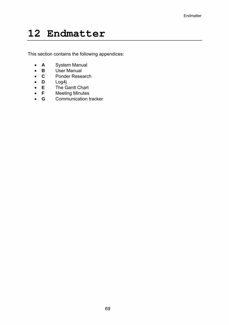
Endmatter
12 Endmatter This section contains the following appendices:
• A System Manual • B User Manual • C Ponder Research • D Log4j • E The Gantt Chart • F Meeting Minutes • G Communication tracker
69
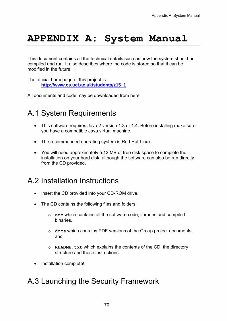
Appendix A: System Manual
APPENDIX A: System Manual This document contains all the technical details such as how the system should be compiled and run. It also describes where the code is stored so that it can be modified in the future. The official homepage of this project is: http://www.cs.ucl.ac.uk/students/z15_1 All documents and code may be downloaded from here.
A.1 System Requirements
• This software requires Java 2 version 1.3 or 1.4. Before installing make sure you have a compatible Java virtual machine.
• The recommended operating system is Red Hat Linux.
• You will need approximately 5.13 MB of free disk space to complete the installation on your hard disk, although the software can also be run directly from the CD provided.
A.2 Installation Instructions
• Insert the CD provided into your CD-ROM drive.
• The CD contains the following files and folders:
o src which contains all the software code, libraries and compiled binaries,
o docs which contains PDF versions of the Group project documents, and
o README.txt which explains the contents of the CD, the directory structure and these instructions.
• Installation complete!
A.3 Launching the Security Framework
70
Appendix A: System Manual
• Change to the src directory: cd src/
• On UNIX-based systems (Recommended):
o Start the framework by typing runit in your favourite shell. You will see output on the terminal window describing the components being registered and started. Finally you will see the Audit Tool display window.
• On Windows:
o Double click on runreg.bat or type runreg.bat at the command prompt. This will register the components.
o Double click on runit.bat or type runit.bat at the command prompt. This will start up the Security Manager and will display the Audit Tool.
• The Security Framework is now up and running!
A.4 Running the Sample Chat Application A sample chat application has been provided in the demoapps package. Launch this application by typing: java demoapps.ChatInterface A chat window will be displayed. All text entered in this window will be encrypted by the Zion based on the current context.
A.5 For Developers The src directory contains all the source code, java class libraries and compiled binaries. It also contains the following files and folders:
• .project and .classpath: These files define the project and buildpath settings for Eclipse, which was the Java Development Environment used to build the entire system. Hence the system can be imported directly into Eclipse and worked on.
• runit: A shell script which sets the classpath and runs the ComponentRegistrar and SecurityManager.
• runreg.bat and runit.bat: These are Windows batch files which run the ComponentRegistrar and SecurityManager respectively.
71
Appendix A: System Manual
• SEINIT.txt: Defines port numbers for application types.
• examplePolicies: This directory contains the Ponder security policy (policy.pol), XML security policy (policy.xml) and the XML context representation (context-eg.xml).
• satin.jar: All SATIN source code is present in java archive lib/satin.jar.
72
Appendix B: User Manual
APPENDIX B: User Manual This document aims to provide help and assistance to users of Zion. The purpose of the framework is to dynamically enforce new security measures when context changes. The system includes an Audit Tool which is used for inspecting the state of the system at any point in time and for observing the messages being passed between its various components. The Audit Tool also includes a Context Dialog for triggering context change events. In addition, the “replay” feature is useful for inspecting past sessions. The sections below cover basic usage of the different features provided by the Audit Tool.
B.1 Audit Message Display The top half of the Audit Tool displays messages describing what is going on in the system. It is divided into a Master Pane on the left and a set of Component Panes on the right. The Master Pane displays main messages of the entire system, whereas the individual component panes display what each component is doing. All messages are preceded by the time they were generated and the time of display.
B.2 Adding and Removing Message Panes Individual message panes can be added and removed from the display window by going into the View menu and (de)selecting the pane that you wish to be added or removed.
B.3 State Transition Diagram The diagram in the bottom half of the main window is called the state transition diagram for the system. It shows the states that the system can be in at any time and the transitions between allowable states. These transitions are triggered by events which are labelled on the transition arrows. As events take place, state transitions can be observed. The current state and transition is represented in red to distinguish it from other parts of the diagram.
73
Appendix B: User Manual
B.4 Resizing the State Transition Diagram The diagram can be resized using the following:
• Keyboard: The arrow keys on the keyboard can be used to compress horizontally (←), compress vertically (↑), expand horizontally (→) and expand vertically (↓).
• Menu: The STD menu displays items for resizing the diagram.
• Toolbar: The STD toolbar can be selected via the STD menu. The toolbar docks itself in the diagram window and holds buttons for resizing the diagram.
B.5 Removing the State Transition Diagram The diagram can be removed by going into the View menu and deselecting the STD option. It can be added again by selecting the STD option.
B.6 Changing Context The Context Dialog can be accessed through Menu File Input Context. The dialog holds two tabs, one for inputting context and the other for displaying the XML representation for that context. Context can be changed by selecting a different device, network connection and/or location from the drop down boxes present on the dialog. Pressing the Apply button triggers a context change event and the system responds accordingly.
B.7 Replaying Past Sessions By default, the Audit Tool writes all displayed messages to a log file. This log file can be specified as an argument to the Security Manager before it is run. The replay function allows you to load a previous log session’s messages into the Audit Display. This is done via Menu File Open and then selecting the log file that you wish to be replayed from the File Dialog box. After pressing OK, the Audit Display is populated with messages from the selected log file.
B.8 Getting Help The Help menu displays help information for the Audit Tool and the State Transition Diagram.
74
Appendix B: User Manual
B.9 Exiting the System The system can be exited by Menu File Exit.
75
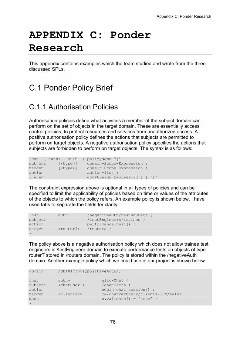
Appendix C: Ponder Research
APPENDIX C: Ponder Research This appendix contains examples which the team studied and wrote from the three discussed SPLs.
C.1 Ponder Policy Brief
C.1.1 Authorisation Policies Authorisation policies define what activities a member of the subject domain can perform on the set of objects in the target domain. These are essentially access control policies, to protect resources and services from unauthorized access. A positive authorisation policy defines the actions that subjects are permitted to perform on target objects. A negative authorisation policy specifies the actions that subjects are forbidden to perform on target objects. The syntax is as follows: inst ( auth+ | auth– ) policyName “{” subject [<type>] domain-Scope-Expression ; target [<type>] domain-Scope-Expression ; action action-list ; [ when constraint-Expression ; ] “}“ The constraint expression above is optional in all types of policies and can be specified to limit the applicability of policies based on time or values of the attributes of the objects to which the policy refers. An example policy is shown below. I have used tabs to separate the fields for clarity. inst auth– /negativeAuth/testRouters { subject /testEngineers/trainee ; action performance_test() ; target <routerT> /routers ; } The policy above is a negative authorisation policy which does not allow trainee test engineers in /testEngineer domain to execute performance tests on objects of type routerT stored in /routers domain. The policy is stored within the /negativeAuth domain. Another example policy which we could use in our project is shown below. domain /SEINIT/pol/positiveAuth/; inst auth+ allowChat { subject <chatUserT> /chatUsers ; action begin_chat_session() ; target <clientsT> c=/chatPartners/clients/IBM/sales ; when c.validate() = “true” ; }
76
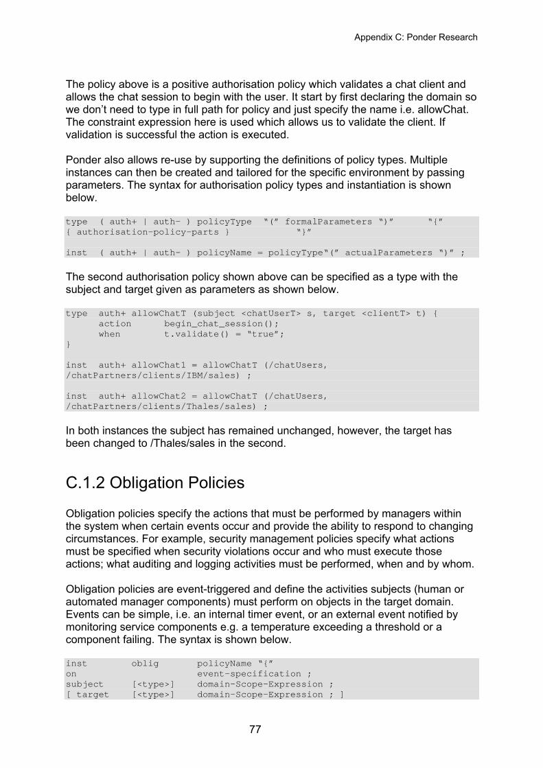
Appendix C: Ponder Research
The policy above is a positive authorisation policy which validates a chat client and allows the chat session to begin with the user. It start by first declaring the domain so we don’t need to type in full path for policy and just specify the name i.e. allowChat. The constraint expression here is used which allows us to validate the client. If validation is successful the action is executed. Ponder also allows re-use by supporting the definitions of policy types. Multiple instances can then be created and tailored for the specific environment by passing parameters. The syntax for authorisation policy types and instantiation is shown below. type ( auth+ | auth– ) policyType “(” formalParameters “)” “{” { authorisation-policy-parts } “}” inst ( auth+ | auth– ) policyName = policyType“(” actualParameters “)” ; The second authorisation policy shown above can be specified as a type with the subject and target given as parameters as shown below. type auth+ allowChatT (subject <chatUserT> s, target <clientT> t) { action begin_chat_session();
when t.validate() = “true”; } inst auth+ allowChat1 = allowChatT (/chatUsers, /chatPartners/clients/IBM/sales) ; inst auth+ allowChat2 = allowChatT (/chatUsers, /chatPartners/clients/Thales/sales) ; In both instances the subject has remained unchanged, however, the target has been changed to /Thales/sales in the second.
C.1.2 Obligation Policies Obligation policies specify the actions that must be performed by managers within the system when certain events occur and provide the ability to respond to changing circumstances. For example, security management policies specify what actions must be specified when security violations occur and who must execute those actions; what auditing and logging activities must be performed, when and by whom. Obligation policies are event-triggered and define the activities subjects (human or automated manager components) must perform on objects in the target domain. Events can be simple, i.e. an internal timer event, or an external event notified by monitoring service components e.g. a temperature exceeding a threshold or a component failing. The syntax is shown below. inst oblig policyName “{” on event-specification ; subject [<type>] domain-Scope-Expression ; [ target [<type>] domain-Scope-Expression ; ]
77
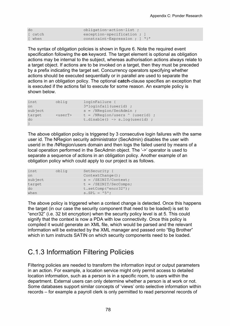
Appendix C: Ponder Research
do obligation-action-list ; [ catch exception-specification ; ] [ when constraint-Expression ; ] “}” The syntax of obligation policies is shown in figure 6. Note the required event specification following the on keyword. The target element is optional as obligation actions may be internal to the subject, whereas authorisation actions always relate to a target object. If actions are to be invoked on a target, then they must be preceded by a prefix indicating the target set. Concurrency operators specifying whether actions should be executed sequentially or in parallel are used to separate the actions in an obligation policy. The optional catch-clause specifies an exception that is executed if the actions fail to execute for some reason. An example policy is shown below. inst oblig loginFailure { on 3*loginfail(userid) ; subject s = /NRegion/SecAdmin ; target <userT> t = /NRegion/users ^ {userid} ; do t.disable() -> s.log(userid) ; } The above obligation policy is triggered by 3 consecutive login failures with the same user id. The NRegion security administrator (SecAdmin) disables the user with userid in the /NRegion/users domain and then logs the failed userid by means of a local operation performed in the SecAdmin object. The ‘->’ operator is used to separate a sequence of actions in an obligation policy. Another example of an obligation policy which could apply to our project is as follows. inst oblig SetSecurity { on ContextChange(); subject s = /SEINIT/Context; target t = /SEINIT/SecComps; do t.setComp("encr32"); when s.SPL = "5"; The above policy is triggered when a context change is detected. Once this happens the target (in our case the security component that need to be loaded) is set to “encr32” (i.e. 32 bit encryption) when the security policy level is at 5. This could signify that the context is now a PDA with low connectivity. Once this policy is compiled it would generate an XML file, which would be parsed and the relevant information will be extracted by the XML manager and passed onto “Big Brother” which in turn instructs SATIN on which security components need to be loaded.
C.1.3 Information Filtering Policies Filtering policies are needed to transform the information input or output parameters in an action. For example, a location service might only permit access to detailed location information, such as a person is in a specific room, to users within the department. External users can only determine whether a person is at work or not. Some databases support similar concepts of ‘views’ onto selective information within records – for example a payroll clerk is only permitted to read personnel records of
78
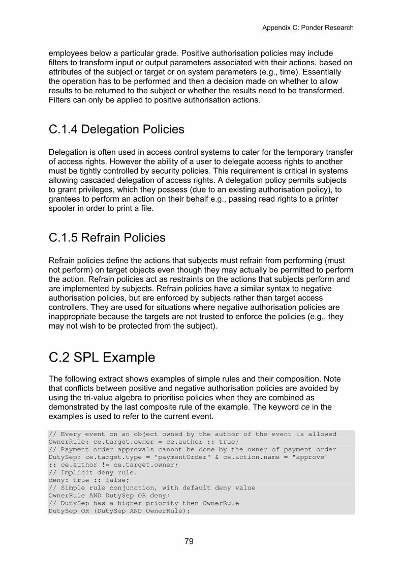
Appendix C: Ponder Research
employees below a particular grade. Positive authorisation policies may include filters to transform input or output parameters associated with their actions, based on attributes of the subject or target or on system parameters (e.g., time). Essentially the operation has to be performed and then a decision made on whether to allow results to be returned to the subject or whether the results need to be transformed. Filters can only be applied to positive authorisation actions.
C.1.4 Delegation Policies Delegation is often used in access control systems to cater for the temporary transfer of access rights. However the ability of a user to delegate access rights to another must be tightly controlled by security policies. This requirement is critical in systems allowing cascaded delegation of access rights. A delegation policy permits subjects to grant privileges, which they possess (due to an existing authorisation policy), to grantees to perform an action on their behalf e.g., passing read rights to a printer spooler in order to print a file.
C.1.5 Refrain Policies Refrain policies define the actions that subjects must refrain from performing (must not perform) on target objects even though they may actually be permitted to perform the action. Refrain policies act as restraints on the actions that subjects perform and are implemented by subjects. Refrain policies have a similar syntax to negative authorisation policies, but are enforced by subjects rather than target access controllers. They are used for situations where negative authorisation policies are inappropriate because the targets are not trusted to enforce the policies (e.g., they may not wish to be protected from the subject).
C.2 SPL Example The following extract shows examples of simple rules and their composition. Note that conflicts between positive and negative authorisation policies are avoided by using the tri-value algebra to prioritise policies when they are combined as demonstrated by the last composite rule of the example. The keyword ce in the examples is used to refer to the current event. // Every event on an object owned by the author of the event is allowed OwnerRule: ce.target.owner = ce.author :: true; // Payment order approvals cannot be done by the owner of payment order DutySep: ce.target.type = "paymentOrder" & ce.action.name = "approve" :: ce.author != ce.target.owner; // Implicit deny rule. deny: true :: false; // Simple rule conjunction, with default deny value OwnerRule AND DutySep OR deny; // DutySep has a higher priority then OwnerRule DutySep OR (DutySep AND OwnerRule);
79
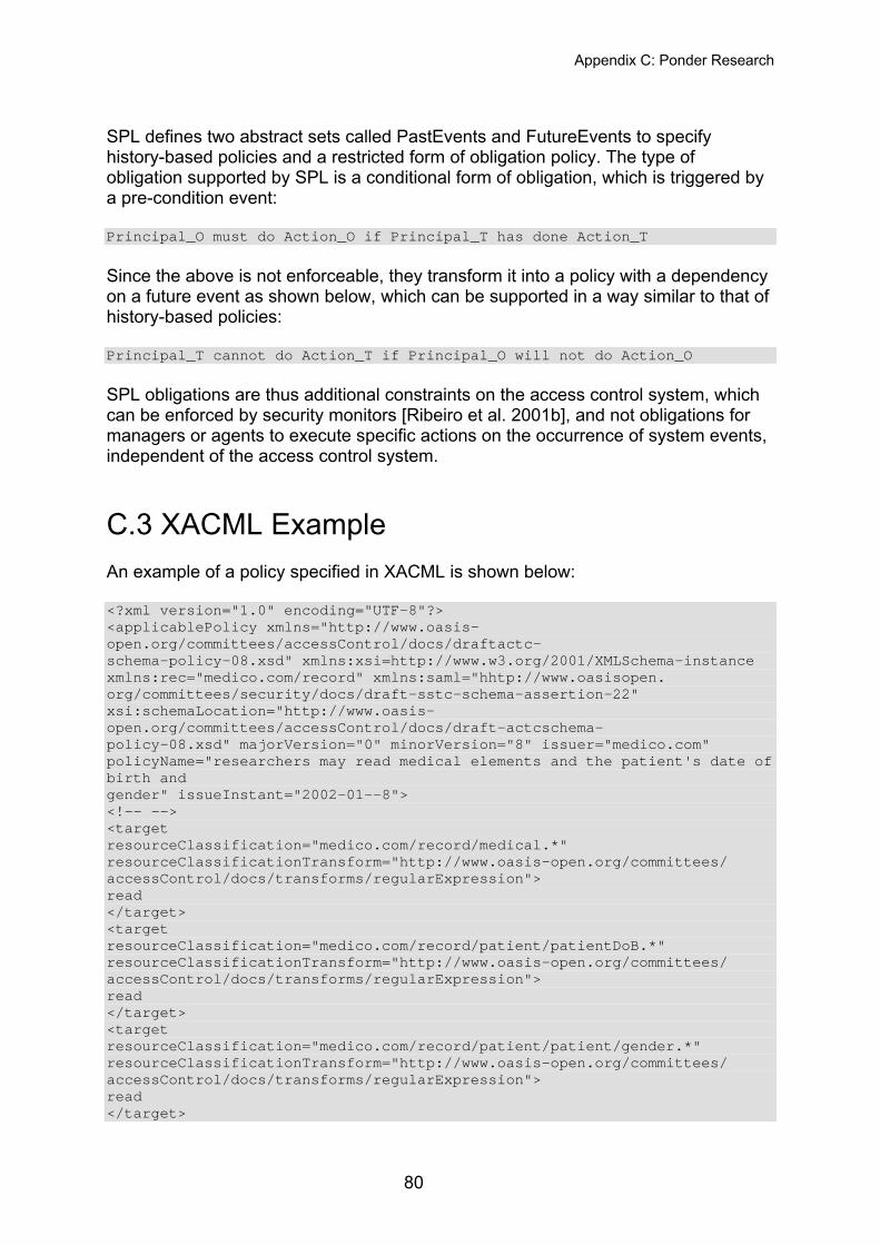
Appendix C: Ponder Research
SPL defines two abstract sets called PastEvents and FutureEvents to specify history-based policies and a restricted form of obligation policy. The type of obligation supported by SPL is a conditional form of obligation, which is triggered by a pre-condition event: Principal_O must do Action_O if Principal_T has done Action_T Since the above is not enforceable, they transform it into a policy with a dependency on a future event as shown below, which can be supported in a way similar to that of history-based policies: Principal_T cannot do Action_T if Principal_O will not do Action_O SPL obligations are thus additional constraints on the access control system, which can be enforced by security monitors [Ribeiro et al. 2001b], and not obligations for managers or agents to execute specific actions on the occurrence of system events, independent of the access control system.
C.3 XACML Example An example of a policy specified in XACML is shown below: <?xml version="1.0" encoding="UTF-8"?> <applicablePolicy xmlns="http://www.oasis-open.org/committees/accessControl/docs/draftactc- schema-policy-08.xsd" xmlns:xsi=http://www.w3.org/2001/XMLSchema-instance xmlns:rec="medico.com/record" xmlns:saml="hhtp://www.oasisopen. org/committees/security/docs/draft-sstc-schema-assertion-22" xsi:schemaLocation="http://www.oasis-open.org/committees/accessControl/docs/draft-actcschema- policy-08.xsd" majorVersion="0" minorVersion="8" issuer="medico.com" policyName="researchers may read medical elements and the patient's date of birth and gender" issueInstant="2002-01--8"> <!-- --> <target resourceClassification="medico.com/record/medical.*" resourceClassificationTransform="http://www.oasis-open.org/committees/ accessControl/docs/transforms/regularExpression"> read </target> <target resourceClassification="medico.com/record/patient/patientDoB.*" resourceClassificationTransform="http://www.oasis-open.org/committees/ accessControl/docs/transforms/regularExpression"> read </target> <target resourceClassification="medico.com/record/patient/patient/gender.*" resourceClassificationTransform="http://www.oasis-open.org/committees/ accessControl/docs/transforms/regularExpression"> read </target>
80
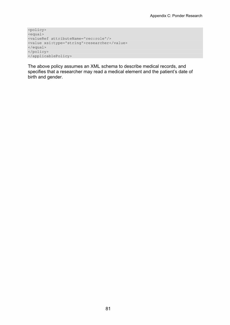
Appendix C: Ponder Research
<policy> <equal> <valueRef attributeName="rec:role"/> <value xsi:type="string">researcher</value> </equal> </policy> </applicablePolicy> The above policy assumes an XML schema to describe medical records, and specifies that a researcher may read a medical element and the patient’s date of birth and gender.
81
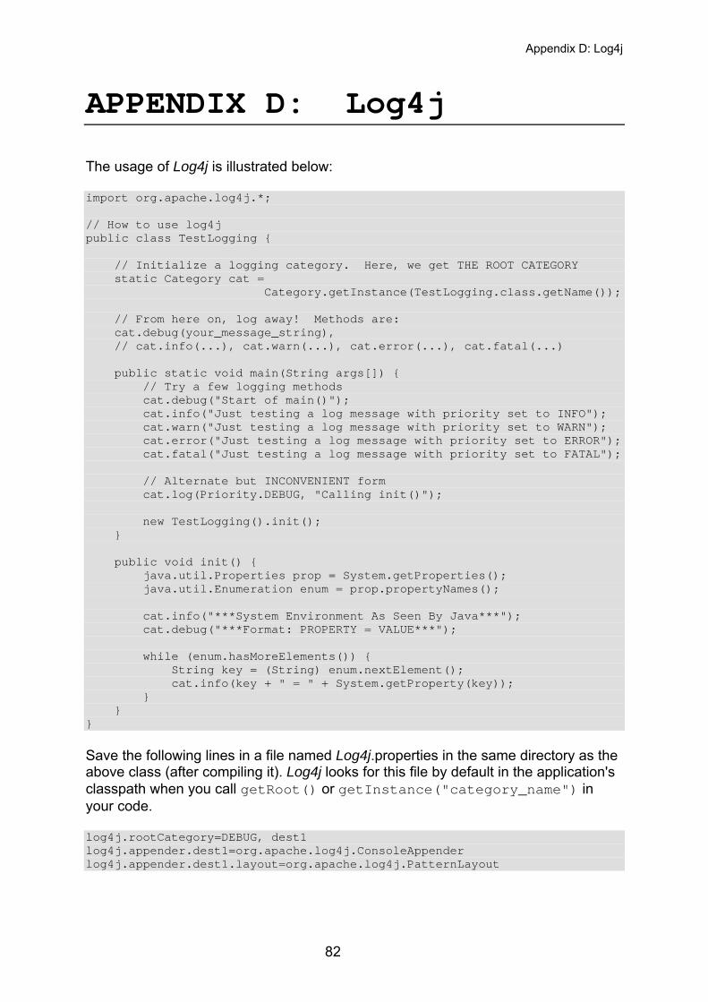
Appendix D: Log4j
APPENDIX D: Log4j The usage of Log4j is illustrated below: import org.apache.log4j.*; // How to use log4j public class TestLogging { // Initialize a logging category. Here, we get THE ROOT CATEGORY static Category cat = Category.getInstance(TestLogging.class.getName()); // From here on, log away! Methods are: cat.debug(your_message_string), // cat.info(...), cat.warn(...), cat.error(...), cat.fatal(...) public static void main(String args[]) { // Try a few logging methods cat.debug("Start of main()"); cat.info("Just testing a log message with priority set to INFO"); cat.warn("Just testing a log message with priority set to WARN"); cat.error("Just testing a log message with priority set to ERROR"); cat.fatal("Just testing a log message with priority set to FATAL"); // Alternate but INCONVENIENT form cat.log(Priority.DEBUG, "Calling init()"); new TestLogging().init(); } public void init() { java.util.Properties prop = System.getProperties(); java.util.Enumeration enum = prop.propertyNames(); cat.info("***System Environment As Seen By Java***"); cat.debug("***Format: PROPERTY = VALUE***"); while (enum.hasMoreElements()) { String key = (String) enum.nextElement(); cat.info(key + " = " + System.getProperty(key)); } } } Save the following lines in a file named Log4j.properties in the same directory as the above class (after compiling it). Log4j looks for this file by default in the application's classpath when you call getRoot() or getInstance("category_name") in your code. log4j.rootCategory=DEBUG, dest1 log4j.appender.dest1=org.apache.log4j.ConsoleAppender log4j.appender.dest1.layout=org.apache.log4j.PatternLayout
82
Appendix D: Log4j
The PatternLayout defaults to %m%n which means print your-supplied message and a newline.
If you wish to print the priority that was assigned to the messages, the following line can be appended to the the log4j.properties file. Once this is done save the file. log4j.appender.dest1.layout.ConversionPattern=%-5p: %m%n This line will override the default %m%n. %p will print the message priority, %m is the message itself, %n is the new line character. Since the changes were only made to the properties file and not to any Java code, there is no need to re-compile our test logger file. All that needs to be done is to run it.
83
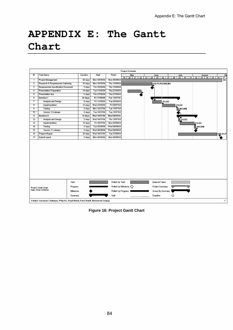
Appendix E: The Gantt Chart
APPENDIX E: The Gantt Chart
Figure 16: Project Gantt Chart
84
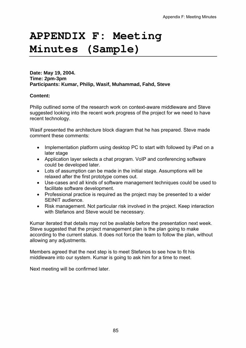
Appendix F: Meeting Minutes
APPENDIX F: Meeting Minutes (Sample) Date: May 19, 2004. Time: 2pm-3pm Participants: Kumar, Philip, Wasif, Muhammad, Fahd, Steve Content: Philip outlined some of the research work on context-aware middleware and Steve suggested looking into the recent work progress of the project for we need to have recent technology. Wasif presented the architecture block diagram that he has prepared. Steve made comment these comments:
• Implementation platform using desktop PC to start with followed by iPad on a later stage
• Application layer selects a chat program. VoIP and conferencing software could be developed later.
• Lots of assumption can be made in the initial stage. Assumptions will be relaxed after the first prototype comes out.
• Use-cases and all kinds of software management techniques could be used to facilitate software development.
• Professional practice is required as the project may be presented to a wider SEINIT audience.
• Risk management. Not particular risk involved in the project. Keep interaction with Stefanos and Steve would be necessary.
Kumar iterated that details may not be available before the presentation next week. Steve suggested that the project management plan is the plan going to make according to the current status. It does not force the team to follow the plan, without allowing any adjustments. Members agreed that the next step is to meet Stefanos to see how to fit his middleware into our system. Kumar is going to ask him for a time to meet. Next meeting will be confirmed later.
85
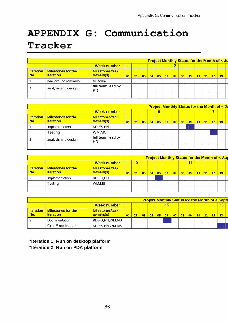
Appendix G: Communication Tracker
APPENDIX G: Communication Tracker
Project Monthly Status for the Month of < Ju Week number 1 2
Iteration No.
Milestones for the Iteration
Milestones/task owners(s) 01 02 03 04 05 06 07 08 09 10 11 12 13 1
1 background research full team
1 analysis and design full team lead by KD
Project Monthly Status for the Month of < Ju Week number 6 7
Iteration No.
Milestones for the Iteration
Milestones/task owners(s) 01 02 03 04 05 06 07 08 09 10 11 12 13 1
1 Implementation KD,FS,PH Testing WM,MS
2 analysis and design full team lead by KD
Project Monthly Status for the Month of < Aug Week number 10 11
Iteration No.
Milestones for the Iteration
Milestones/task owners(s) 01 02 03 04 05 06 07 08 09 10 11 12 13 1
2 Implementation KD,FS,PH Testing WM,MS
Project Monthly Status for the Month of < Septe Week number 15 16
Iteration No.
Milestones for the Iteration
Milestones/task owners(s) 01 02 03 04 05 06 07 08 09 10 11 12 13 1
2 Documentation KD,FS,PH,WM,MS Oral Examination KD,FS,PH,WM,MS *Iteration 1: Run on desktop platform *Iteration 2: Run on PDA platform
86
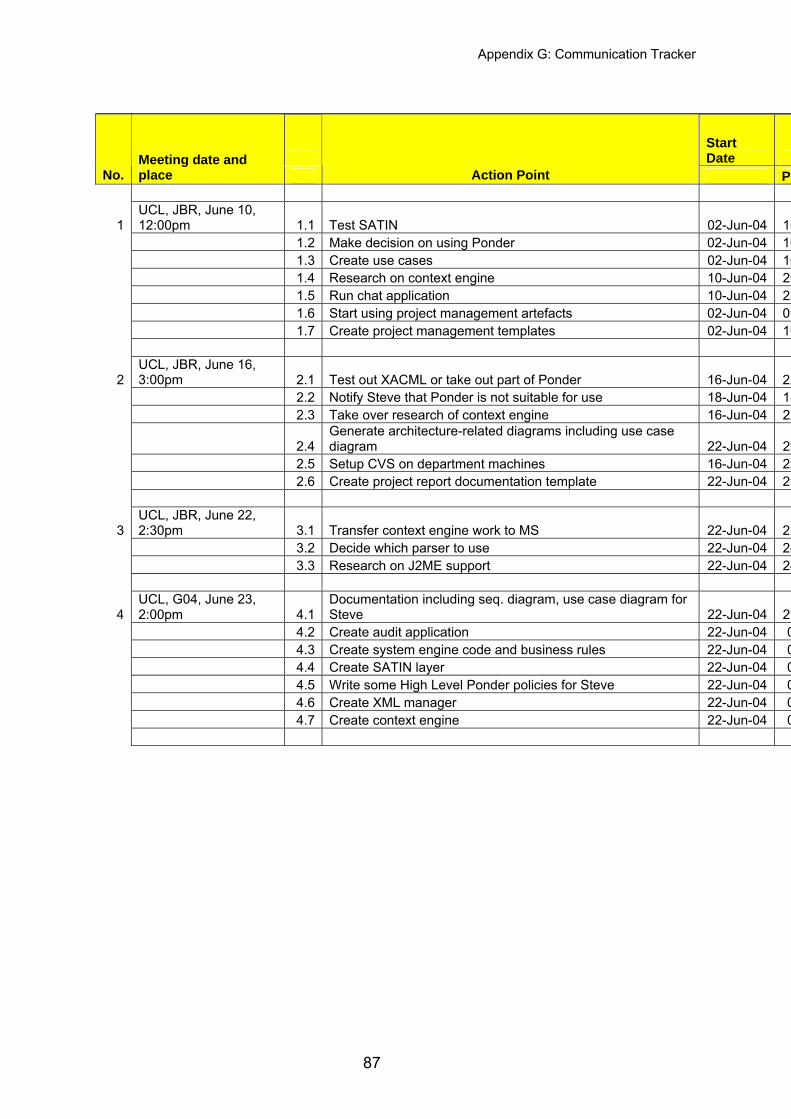
Appendix G: Communication Tracker
Start Date
No. Meeting date and place Action Point P
1 UCL, JBR, June 10, 12:00pm 1.1 Test SATIN 02-Jun-04 10
1.2 Make decision on using Ponder 02-Jun-04 16 1.3 Create use cases 02-Jun-04 16 1.4 Research on context engine 10-Jun-04 20 1.5 Run chat application 10-Jun-04 22 1.6 Start using project management artefacts 02-Jun-04 09 1.7 Create project management templates 02-Jun-04 10
2 UCL, JBR, June 16, 3:00pm 2.1 Test out XACML or take out part of Ponder 16-Jun-04 22
2.2 Notify Steve that Ponder is not suitable for use 18-Jun-04 18 2.3 Take over research of context engine 16-Jun-04 22
2.4 Generate architecture-related diagrams including use case diagram 22-Jun-04 29
2.5 Setup CVS on department machines 16-Jun-04 22 2.6 Create project report documentation template 22-Jun-04 29
3 UCL, JBR, June 22, 2:30pm 3.1 Transfer context engine work to MS 22-Jun-04 23
3.2 Decide which parser to use 22-Jun-04 24 3.3 Research on J2ME support 22-Jun-04 24
4 UCL, G04, June 23, 2:00pm 4.1
Documentation including seq. diagram, use case diagram for Steve 22-Jun-04 29
4.2 Create audit application 22-Jun-04 0 4.3 Create system engine code and business rules 22-Jun-04 0 4.4 Create SATIN layer 22-Jun-04 0 4.5 Write some High Level Ponder policies for Steve 22-Jun-04 0 4.6 Create XML manager 22-Jun-04 0 4.7 Create context engine 22-Jun-04 0
87
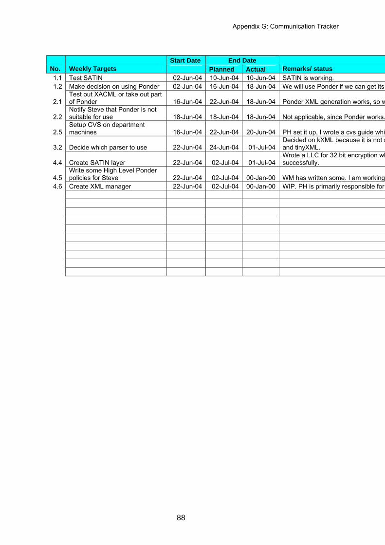
Appendix G: Communication Tracker
Start Date End Date
No. Weekly Targets Planned Actual Remarks/ status 1.1 Test SATIN 02-Jun-04 10-Jun-04 10-Jun-04 SATIN is working. 1.2 Make decision on using Ponder 02-Jun-04 16-Jun-04 18-Jun-04 We will use Ponder if we can get its
2.1 Test out XACML or take out part of Ponder 16-Jun-04 22-Jun-04 18-Jun-04 Ponder XML generation works, so w
2.2 Notify Steve that Ponder is not suitable for use 18-Jun-04 18-Jun-04 18-Jun-04 Not applicable, since Ponder works.
2.5 Setup CVS on department machines 16-Jun-04 22-Jun-04 20-Jun-04 PH set it up, I wrote a cvs guide whi
3.2 Decide which parser to use 22-Jun-04 24-Jun-04 01-Jul-04 Decided on kXML because it is not aand tinyXML.
4.4 Create SATIN layer 22-Jun-04 02-Jul-04 01-Jul-04 Wrote a LLC for 32 bit encryption whsuccessfully.
4.5 Write some High Level Ponder policies for Steve 22-Jun-04 02-Jul-04 00-Jan-00 WM has written some. I am working
4.6 Create XML manager 22-Jun-04 02-Jul-04 00-Jan-00 WIP. PH is primarily responsible for
88