Embed Size (px)
Citation preview
ZT-2100 / ZT-2200 (EZT®)Integrated Zero-Turn Transaxle
Service and Repair ManualBLN-52622May 2013
ZT-2200(EZT®)
ZT-2100
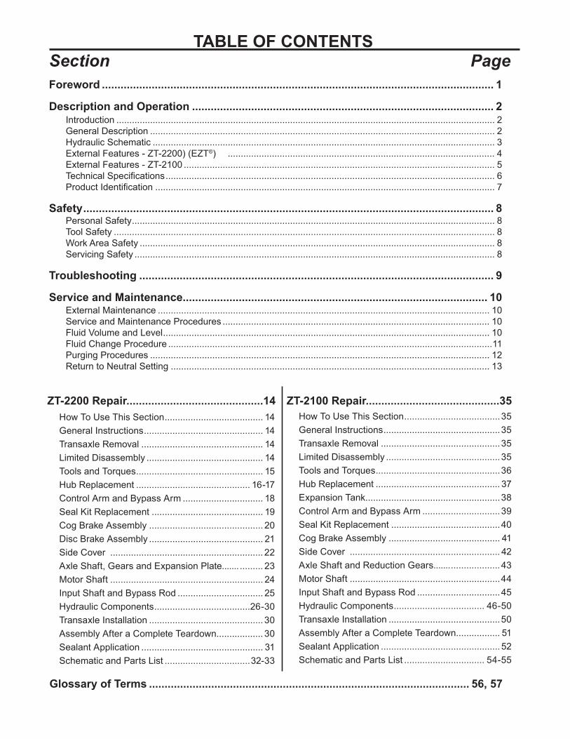
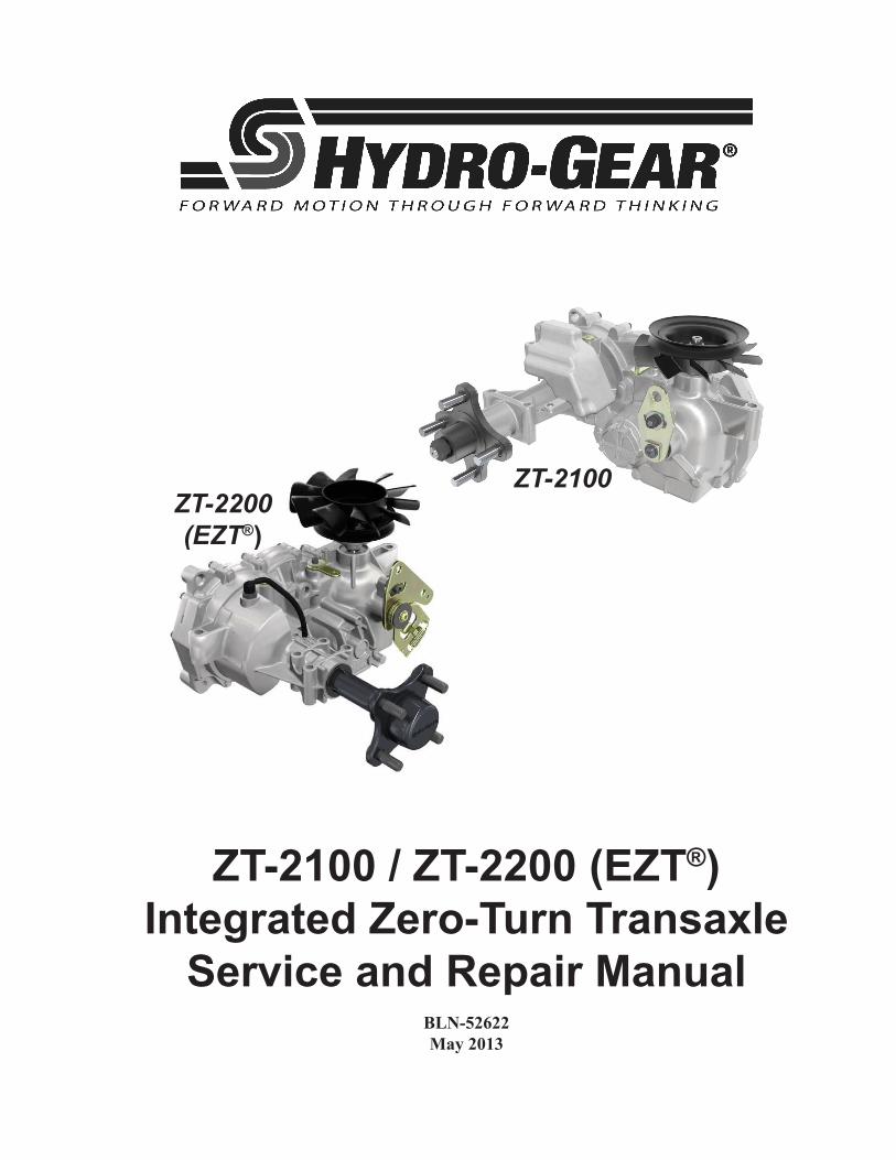
TABLE OF CONTENTSSection PageForeword .............................................................................................................................. 1
Description and Operation ................................................................................................. 2Introduction .................................................................................................................................................. 2General Description ..................................................................................................................................... 2Hydraulic Schematic .................................................................................................................................... 3External Features - ZT-2200) (EZT®) ....................................................................................................... 4External Features - ZT-2100 ........................................................................................................................ 5Technical Specifications ............................................................................................................................... 6Product Identification ................................................................................................................................... 7
Safety .................................................................................................................................... 8Personal Safety ............................................................................................................................................ 8Tool Safety ................................................................................................................................................... 8Work Area Safety ......................................................................................................................................... 8Servicing Safety ........................................................................................................................................... 8
Troubleshooting .................................................................................................................. 9
Service and Maintenance.................................................................................................. 10External Maintenance ................................................................................................................................ 10Service and Maintenance Procedures ....................................................................................................... 10Fluid Volume and Level .............................................................................................................................. 10Fluid Change Procedure .............................................................................................................................11Purging Procedures ................................................................................................................................... 12Return to Neutral Setting ........................................................................................................................... 13
How To Use This Section ...................................... 14General Instructions .............................................. 14Transaxle Removal ............................................... 14Limited Disassembly ............................................. 14Tools and Torques ................................................. 15Hub Replacement ............................................ 16-17Control Arm and Bypass Arm ............................... 18Seal Kit Replacement ........................................... 19Cog Brake Assembly ............................................ 20Disc Brake Assembly ............................................ 21Side Cover ........................................................... 22Axle Shaft, Gears and Expansion Plate....... ......... 23Motor Shaft ........................................................... 24Input Shaft and Bypass Rod ................................. 25Hydraulic Components .....................................26-30Transaxle Installation ............................................ 30Assembly After a Complete Teardown.................. 30Sealant Application ............................................... 31Schematic and Parts List .................................32-33
Glossary of Terms ....................................................................................................... 56, 57
How To Use This Section .....................................35General Instructions .............................................35Transaxle Removal ..............................................35Limited Disassembly ............................................35Tools and Torques ................................................36Hub Replacement ................................................ 37Expansion Tank ....................................................38Control Arm and Bypass Arm ..............................39Seal Kit Replacement ..........................................40Cog Brake Assembly ........................................... 41Side Cover .......................................................... 42Axle Shaft and Reduction Gears....... ...................43Motor Shaft ..........................................................44Input Shaft and Bypass Rod ................................45Hydraulic Components ................................... 46-50Transaxle Installation ...........................................50Assembly After a Complete Teardown................. 51Sealant Application .............................................. 52Schematic and Parts List ............................... 54-55
ZT-2200 Repair............................................14 ZT-2100 Repair...........................................35
ZT-2100 / ZT-2200 (EZT®) 1
foreword
Headquartered in Sullivan, Illinois, Hydro-Gear® is a world leader in the design, manufacture, and service of quality hydrostatic transaxles for the lawn and garden industry. The mission of our company is to be recognized by our custom-ers and the industry as a world-class supplier and the quality leader in everything we do.
This Service and Repair Manual is designed to provide information useful in servicing and troubleshooting the Hydro-Gear ZT-2200 (EZT®) and ZT-2100 Integrated Zero-Turn Transaxle.
Also included is a glossary of terms that are frequently used throughout the industry and in Hydro-Gear service publications. Understand-ing terminology is very important!
It is necessary, and a good shop practice, that your service area be equipped with the proper tools and the mechanics be supplied the latest information available. All repair procedures illustrated in this guide are suggested, but pre-
ferred methods of repair.
Repair procedures require that the transaxle unit be removed from the vehicle.
This is not a certification, test or study guide for a certification test. If a technician is interested in certification, they should contact an agent representing OPEESA (Outdoor Power Equip-ment and Engine Service Association) at (860) 767-1770 or their Hydro-Gear Central Service Distributor. Many distributors will be hosting certification testing. These study guides will cover most of the products and manufacturers in our industry.
For more information about Hydro-Gear or our products, please contact your Central Service Distributor, or call our Customer Service Depart-ment at (217) 728-2581.
2 ZT-2100 / ZT-2200 (EZT®)
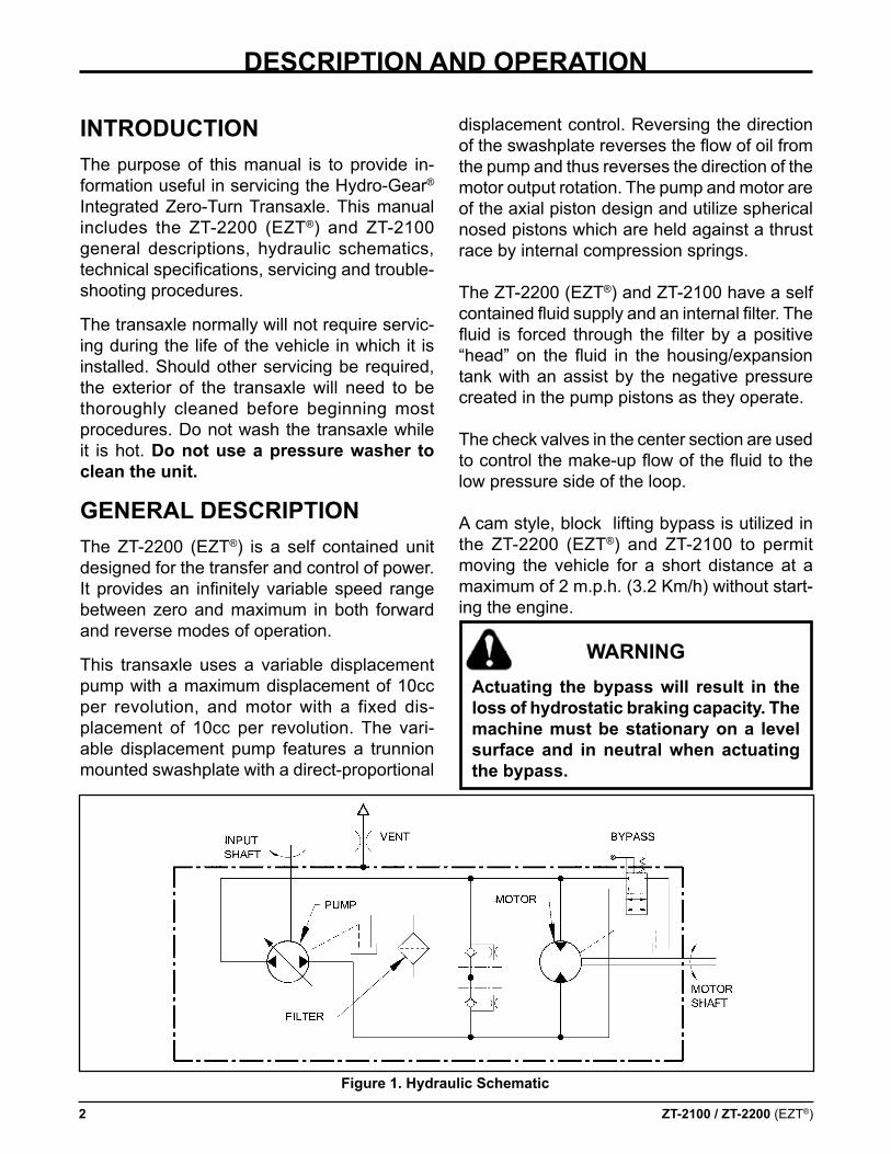
displacement control. Reversing the direction of the swashplate reverses the flow of oil from the pump and thus reverses the direction of the motor output rotation. The pump and motor are of the axial piston design and utilize spherical nosed pistons which are held against a thrust race by internal compression springs.
The ZT-2200 (EZT®) and ZT-2100 have a self contained fluid supply and an internal filter. The fluid is forced through the filter by a positive “head” on the fluid in the housing/expansion tank with an assist by the negative pressure created in the pump pistons as they operate.
The check valves in the center section are used to control the make-up flow of the fluid to the low pressure side of the loop.
A cam style, block lifting bypass is utilized in the ZT-2200 (EZT®) and ZT-2100 to permit moving the vehicle for a short distance at a maximum of 2 m.p.h. (3.2 Km/h) without start-ing the engine.
warning actuating the bypass will result in the loss of hydrostatic braking capacity. The machine must be stationary on a level surface and in neutral when actuating the bypass.
inTroducTionThe purpose of this manual is to provide in-formation useful in servicing the Hydro-Gear® Integrated Zero-Turn Transaxle. This manual includes the ZT-2200 (EZT®) and ZT-2100 general descriptions, hydraulic schematics, technical specifications, servicing and trouble-shooting procedures.
The transaxle normally will not require servic-ing during the life of the vehicle in which it is installed. Should other servicing be required, the exterior of the transaxle will need to be thoroughly cleaned before beginning most procedures. Do not wash the transaxle while it is hot. do not use a pressure washer to clean the unit.
general descripTionThe ZT-2200 (EZT®) is a self contained unit designed for the transfer and control of power. It provides an infinitely variable speed range between zero and maximum in both forward and reverse modes of operation.
This transaxle uses a variable displacement pump with a maximum displacement of 10cc per revolution, and motor with a fixed dis-placement of 10cc per revolution. The vari-able displacement pump features a trunnion mounted swashplate with a direct-proportional
descripTion and operaTion
figure 1. Hydraulic schematic
ZT-2100 / ZT-2200 (EZT®) 3
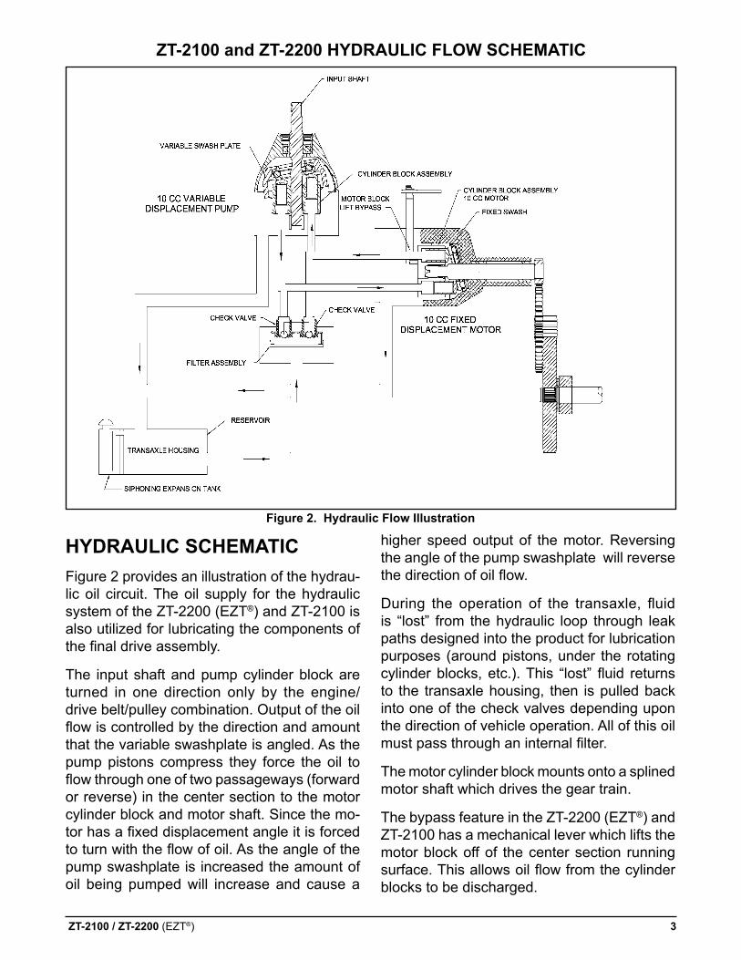
HYdraulic scHeMaTicFigure 2 provides an illustration of the hydrau-lic oil circuit. The oil supply for the hydraulic system of the ZT-2200 (EZT®) and ZT-2100 is also utilized for lubricating the components of the final drive assembly.
The input shaft and pump cylinder block are turned in one direction only by the engine/drive belt/pulley combination. Output of the oil flow is controlled by the direction and amount that the variable swashplate is angled. As the pump pistons compress they force the oil to flow through one of two passageways (forward or reverse) in the center section to the motor cylinder block and motor shaft. Since the mo-tor has a fixed displacement angle it is forced to turn with the flow of oil. As the angle of the pump swashplate is increased the amount of oil being pumped will increase and cause a
higher speed output of the motor. Reversing the angle of the pump swashplate will reverse the direction of oil flow.
During the operation of the transaxle, fluid is “lost” from the hydraulic loop through leak paths designed into the product for lubrication purposes (around pistons, under the rotating cylinder blocks, etc.). This “lost” fluid returns to the transaxle housing, then is pulled back into one of the check valves depending upon the direction of vehicle operation. All of this oil must pass through an internal filter.
The motor cylinder block mounts onto a splined motor shaft which drives the gear train.
The bypass feature in the ZT-2200 (EZT®) and ZT-2100 has a mechanical lever which lifts the motor block off of the center section running surface. This allows oil flow from the cylinder blocks to be discharged.
figure 2. Hydraulic flow illustration
ZT-2100 and ZT-2200 HYdraulic flow scHeMaTic
4 ZT-2100 / ZT-2200 (EZT®)
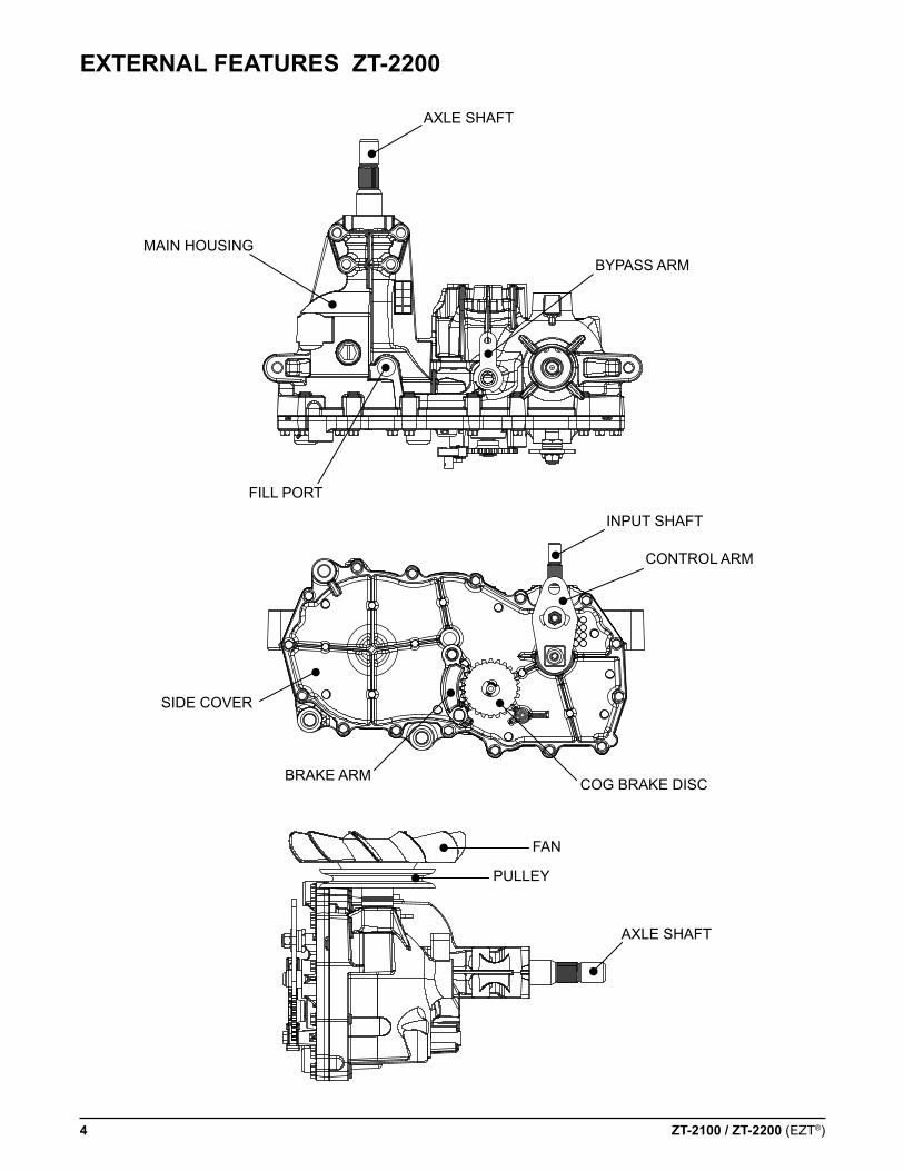
eXTernal feaTures ZT-2200
AXLE SHAFT
BYPASS ARMMAIN HOUSING
FILL PORT
INPUT SHAFT
CONTROL ARM
COG BRAKE DISCBRAKE ARM
SIDE COVER
FAN
PULLEY
AXLE SHAFT
ZT-2100 / ZT-2200 (EZT®) 5
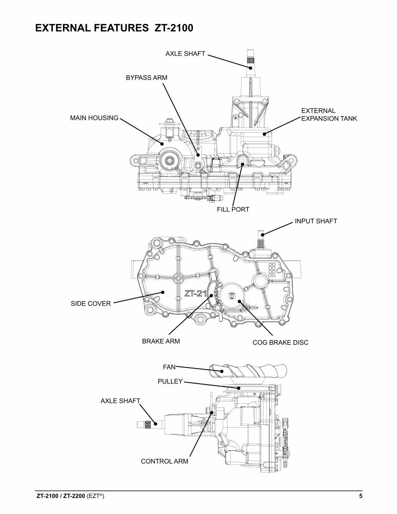
eXTernal feaTures ZT-2100
AXLE SHAFT
MAIN HOUSING EXTERNAL EXPANSION TANK
FILL PORT
BYPASS ARM
INPUT SHAFT
COG BRAKE DISCBRAKE ARM
SIDE COVER
PULLEY
FAN
AXLE SHAFT
CONTROL ARM
6 ZT-2100 / ZT-2200 (EZT®)
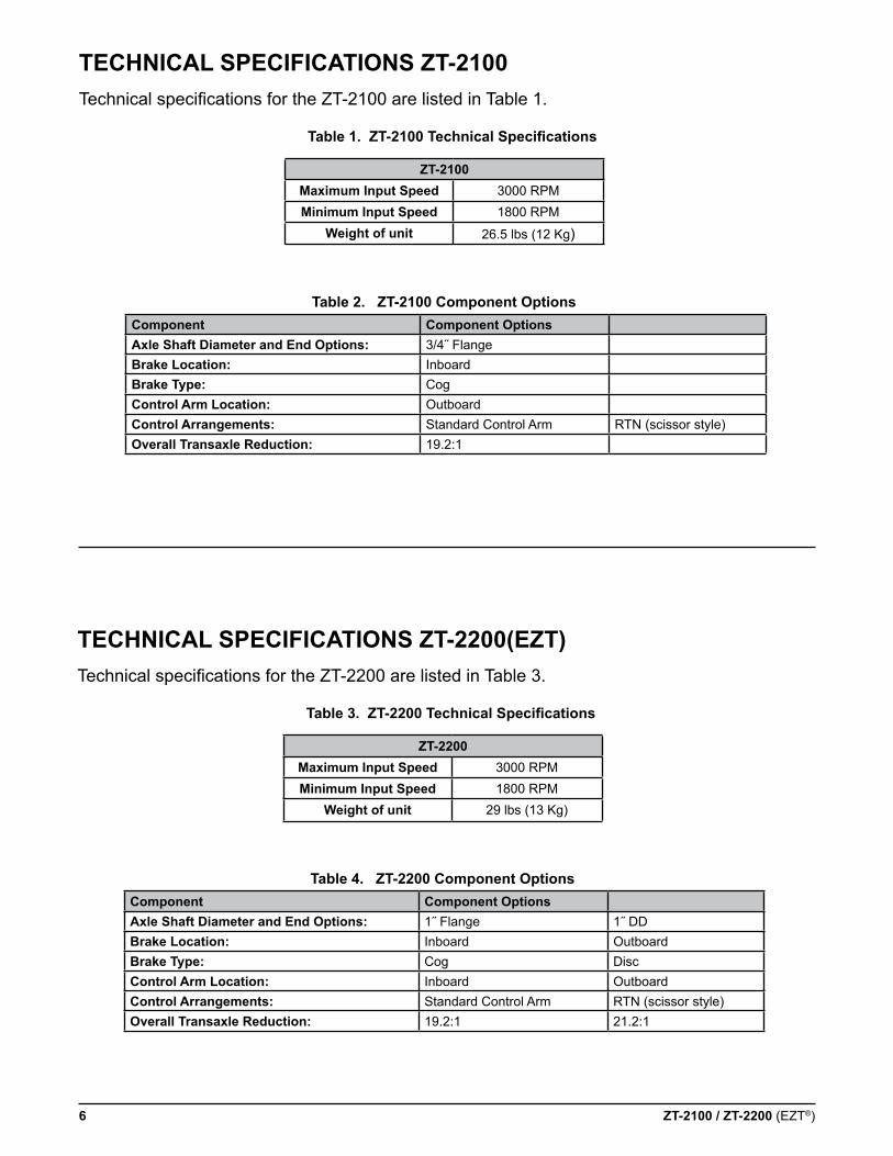
TecHnical specificaTions ZT-2100Technical specifications for the ZT-2100 are listed in Table 1.
component component optionsaxle shaft diameter and end options: 3/4˝ FlangeBrake location: InboardBrake Type: Cogcontrol arm location: Outboardcontrol arrangements: Standard Control Arm RTN (scissor style)overall Transaxle reduction: 19.2:1
Table 1. ZT-2100 Technical Specifications
Table 2. ZT-2100 component options
ZT-2100Maximum input speed 3000 RPMMinimum input speed 1800 RPM
weight of unit 26.5 lbs (12 Kg)
TecHnical specificaTions ZT-2200(eZT)Technical specifications for the ZT-2200 are listed in Table 3.
component component optionsaxle shaft diameter and end options: 1˝ Flange 1˝ DDBrake location: Inboard OutboardBrake Type: Cog Disccontrol arm location: Inboard Outboardcontrol arrangements: Standard Control Arm RTN (scissor style)overall Transaxle reduction: 19.2:1 21.2:1
Table 3. ZT-2200 Technical Specifications
Table 4. ZT-2200 component options
ZT-2200Maximum input speed 3000 RPMMinimum input speed 1800 RPM
weight of unit 29 lbs (13 Kg)
ZT-2100 / ZT-2200 (EZT®) 7
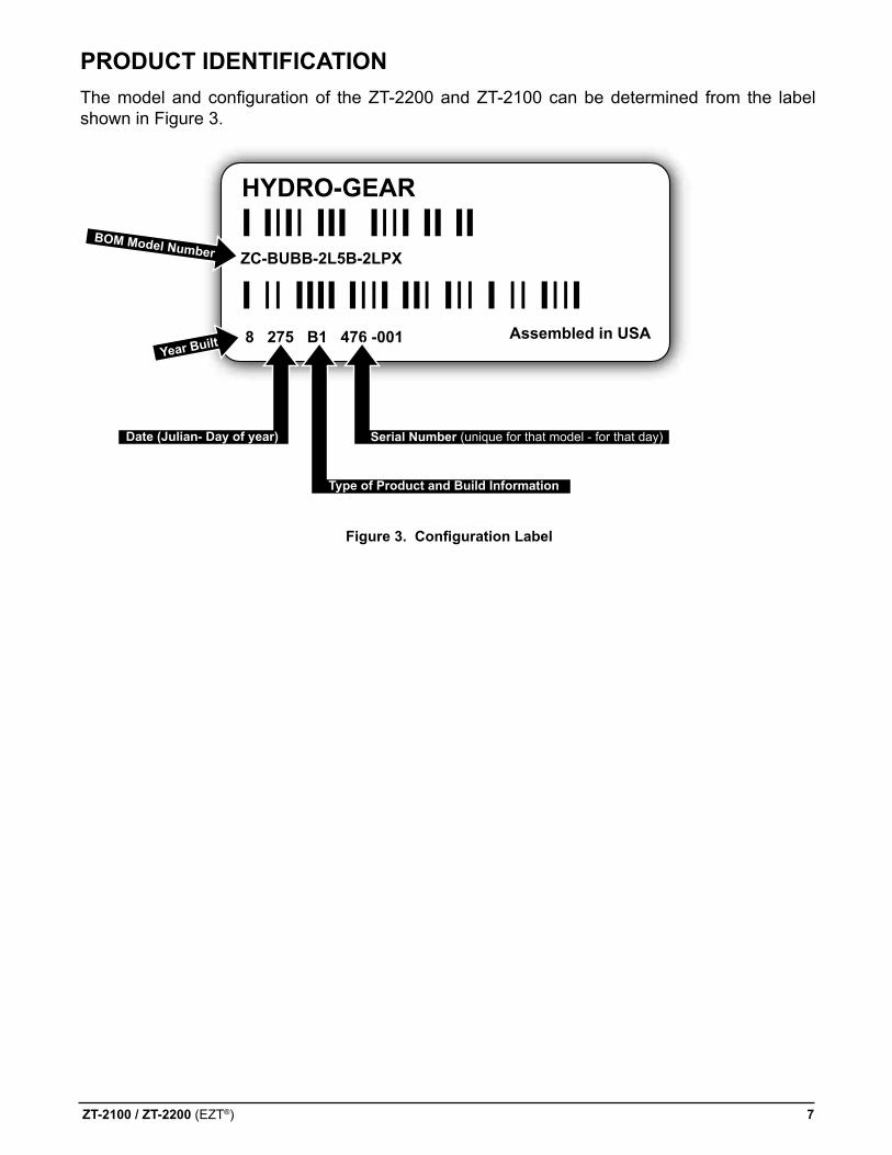
producT idenTificaTionThe model and configuration of the ZT-2200 and ZT-2100 can be determined from the label shown in Figure 3.
Figure 3. Configuration Label
HYDRO-GEAR
Assembled in USAYear Built
ZC-BUBB-2L5B-2LPX
8 275 B1 476 -001
BOM Model Number
Date (Julian- Day of year) Serial Number (unique for that model - for that day)
Type of Product and Build Information
8 ZT-2100 / ZT-2200 (EZT®)
This symbol points out important safety instructions which, if not followed, could endan-ger the personal safety and/or property of your-self and others. Read and follow all instruc-tions in this manual before attempting main-tenance on your transaxle. When you see this symbol - Heed iTs warning.
warning
poTenTial for serious injurY
inattention to proper safety, operation, or maintenance procedures could result in personal injury, or damage to the equip-ment. Before servicing or repairing the ZT-2100 or ZT-2200 (eZT®), fully read and understand the safety precautions described in this section.
personal safeTYCertain safety precautions must be observed while servicing or repairing the ZT2100 or ZT-2200 (EZT®). This section addresses some of these precautions but must not be considered an all-inclusive source on safety information. This section is to be used in conjunction with all other safety material which may apply, such as:
1) Other manuals pertaining to this machine,2) Local and shop safety rules and codes,3) Governmental safety laws and regula-tions.
Be sure that you know and understand the equipment and the hazards associated with it. Do not place speed above safety.
Notify your supervisor whenever you feel there is any hazard involving the equipment or the performance of your job.
Never allow untrained or unauthorized person-nel to service or repair the equipment.
Wear appropriate clothing. Loose or hanging clothing or jewelry can be hazardous. Use the appropriate safety equipment, such as eye and hearing protection, and safety-toe and slip-proof shoes.
Never use compressed air to clean debris from yourself or your clothing.
Tool safeTYUse the proper tools and equipment for the task.
Inspect each tool before use and replace any tool that may be damaged or defective.
worK area safeTYKeep the work area neat and orderly. Be sure it is well lit, that extra tools are put away, trash and refuse are in the proper containers, and dirt or debris have been removed from the working areas of the machine.
The floor should be clean and dry, and all ex-tension cords or similar trip hazards should be removed.
servicing safeTYCertain procedures may require the vehicle to be disabled in order to prevent possible injury to the servicing technician and/or bystanders.
The loss of hydrostatic drive line power may result in the loss of hydrostatic braking capa-bility.
Some cleaning solvents are flammable. Use only approved cleaning materials: Do not use explosive or flammable liquids to clean the equipment.
To avoid possible fire, do not use cleaning solvents in an area where a source of ignition may be present.
Discard used cleaning material in the appropri-ate containers.
safeTY
ZT-2100 / ZT-2200 (EZT®) 9
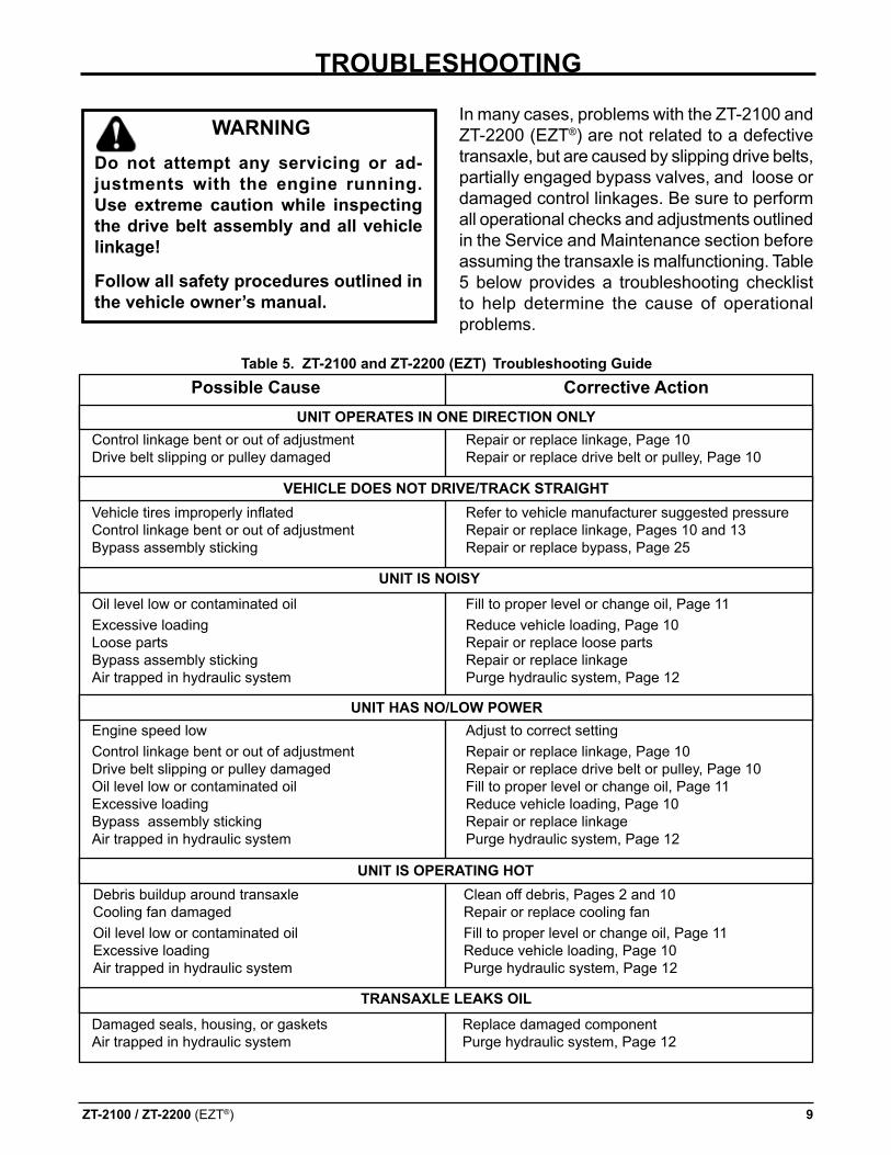
Vehicle tires improperly inflated Refer to vehicle manufacturer suggested pressureControl linkage bent or out of adjustment Repair or replace linkage, Pages 10 and 13Bypass assembly sticking Repair or replace bypass, Page 25
warningdo not attempt any servicing or ad-justments with the engine running. use extreme caution while inspecting the drive belt assembly and all vehicle linkage!
follow all safety procedures outlined in the vehicle owner’s manual.
TrouBlesHooTing
In many cases, problems with the ZT-2100 and ZT-2200 (EZT®) are not related to a defective transaxle, but are caused by slipping drive belts, partially engaged bypass valves, and loose or damaged control linkages. Be sure to perform all operational checks and adjustments outlined in the Service and Maintenance section before assuming the transaxle is malfunctioning. Table 5 below provides a troubleshooting checklist to help determine the cause of operational problems.
Table 5. ZT-2100 and ZT-2200 (eZT) Troubleshooting guidepossible cause corrective action
uniT operaTes in one direcTion onlY
uniT is noisY
uniT Has no/low power
TransaXle leaKs oil
Control linkage bent or out of adjustment Repair or replace linkage, Page 10Drive belt slipping or pulley damaged Repair or replace drive belt or pulley, Page 10
Oil level low or contaminated oil Fill to proper level or change oil, Page 11Excessive loading Reduce vehicle loading, Page 10Loose parts Repair or replace loose partsBypass assembly sticking Repair or replace linkageAir trapped in hydraulic system Purge hydraulic system, Page 12
Engine speed low Adjust to correct settingControl linkage bent or out of adjustment Repair or replace linkage, Page 10Drive belt slipping or pulley damaged Repair or replace drive belt or pulley, Page 10Oil level low or contaminated oil Fill to proper level or change oil, Page 11 Excessive loading Reduce vehicle loading, Page 10Bypass assembly sticking Repair or replace linkageAir trapped in hydraulic system Purge hydraulic system, Page 12
Debris buildup around transaxle Clean off debris, Pages 2 and 10Cooling fan damaged Repair or replace cooling fanOil level low or contaminated oil Fill to proper level or change oil, Page 11Excessive loading Reduce vehicle loading, Page 10Air trapped in hydraulic system Purge hydraulic system, Page 12
Damaged seals, housing, or gaskets Replace damaged componentAir trapped in hydraulic system Purge hydraulic system, Page 12
veHicle does noT drive/TracK sTraigHT
uniT is operaTing HoT
10 ZT-2100 / ZT-2200 (EZT®)
fluidsThe fluids used in Hydro-Gear products have been carefully selected, and only equivalent, or better products should be substituted.
Typically, an engine oil with a minimum rating of 9.0 cSt (55 SUS) at 230° F (110° C) and an API classification of SL is recommended. A 20W50 engine oil has been selected for use by the factory and is recommended for normal operating procedures.
fluid voluMe and levelFluid volume information is provided in Table 6, page 11.
Certain situations may require additional fluid to be added or even replaced. Refer to Page 4 and 5 for the proper fill port location.
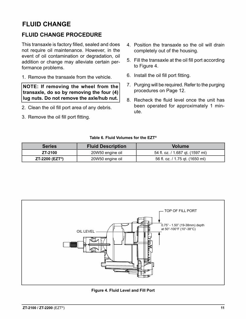
Fill the ZT-2100 and ZT-2200 (EZT®) so the oil level is .75”-1.50” (19-38 mm) below the oil fill port.
A volume of 53.3 fl. oz. to 55.9 fl. oz. should bring the the fluid to the correct level in the transaxle.
Recheck the fluid level once the unit has been operated for approximately 1 minute.
Purging will be required. Refer to the purging procedures on Page 12.
service and MainTenance
noTe: any servicing dealer attempting a warranty repair must have prior ap-proval before conducting maintenance of a Hydro-gear® product unless the servicing dealer is a current authorized Hydro-gear service center.
eXTernal MainTenanceRegular external maintenance of the ZT-2100 and ZT-2200 (EZT®) should include the follow-ing:
1. check the vehicle operator’s manual for the recommended load ratings. insure that the current application does not exceed load rating.
2. Check oil level in accordance with Figure 4 Page 11.
3. Inspect the vehicle drive belt, idler pulley(s), and idler spring(s). Insure that no belt slip-page can occur. Slippage can cause low input speed to the transmission.
4. Inspect the vehicle control linkage to the directional control arm on the transaxle. Also insure that the control arm is securely fas-tened to the trunnion arm of the transaxle.
5. Inspect the bypass mechanism on the trans-axle and the vehicle linkage to insure that both actuate and release fully.
service and MainTenance proceduresSome of the service procedures presented on the following pages can be performed while the transaxle is mounted on the vehicle. Any repair procedures as mentioned in the repair section of this manual must be performed after the unit has been removed from the vehicle. The unit should be thoroughly cleaned before any service procedures are performed.
ZT-2100 / ZT-2200 (EZT®) 11
fluid cHange procedureThis transaxle is factory filled, sealed and does not require oil maintenance. However, in the event of oil contamination or degradation, oil addition or change may alleviate certain per-formance problems.
1. Remove the transaxle from the vehicle.
noTe: if removing the wheel from the transaxle, do so by removing the four (4) lug nuts. do not remove the axle/hub nut.
2. Clean the oil fill port area of any debris.
3. Remove the oil fill port fitting.
4. Position the transaxle so the oil will drain completely out of the housing.
5. Fill the transaxle at the oil fill port according to Figure 4.
6. Install the oil fill port fitting.
7. Purging will be required. Refer to the purging procedures on Page 12.
8. Recheck the fluid level once the unit has been operated for approximately 1 min-ute.
Table 6. fluid volumes for the eZT®
fluid cHange
figure 4. fluid level and fill port
TOP OF FILL PORT
OIL LEVEL
0.75” - 1.50” (19-38mm) depth at 50°-100°F (10°-38°C)
series fluid description volumeZT-2100 20W50 engine oil 54 fl. oz. / 1.687 qt. (1597 ml)
ZT-2200 (eZT®) 20W50 engine oil 56 fl. oz. / 1.75 qt. (1650 ml)
12 ZT-2100 / ZT-2200 (EZT®)
purging proceduresDue to the effects air has on efficiency in hy-drostatic drive applications, it is critical that it is purged from the system.
These purge procedures should be imple-mented any time a hydrostatic system has been opened to facilitate maintenance or any additional oil has been added to the system.
Air creates inefficiency because its compres-sion and expansion rate is higher than that of the oil approved for use in hydrostatic drive systems.
The resulting symptoms in hydrostatic systems may be:
1. Noisy operation.
2. Lack of power or drive after short term op-eration.
3. High operation temperature and excessive expansion of oil.
Before starting, make sure the transaxle/trans-mission is at the proper oil level. If it is not, fill to the specifications outlined on Page 11, Figure 4.
The following procedures should be performed with the vehicle drive wheels off the ground, then repeated under normal operating condi-tions.
1. With the bypass valve open and the engine running, slowly move the directional control in both forward and reverse directions (5 or 6 times), as air is purged from the unit, the oil level will drop.
2. With the bypass valve closed and the engine running, slowly move the directional control in both forward and reverse directions (5 to 6 times). Check the oil level, and add oil as required after stopping the engine.
3. It may be necessary to repeat Steps 1 and 2 until all the air is completely purged from the system. When the transaxle moves for-ward and reverse at normal speed purging is complete.
ZT-2100 / ZT-2200 (EZT®) 13
warning
poTenTial for serious injurY
inattention to proper safety, operation, or maintenance procedures could result in personal injury, or damage to the equip-ment. Before servicing or repairing the ZT-2100 and ZT-2200 (eZT®), fully read and understand the safety precautions described in this section.
warningdo not attempt any servicing or ad-justments with the engine running. use extreme caution while inspecting the drive belt assembly and all vehicle linkage!
follow all safety procedures outlined in the vehicle owner’s manual.
reTurn To neuTral seTTing
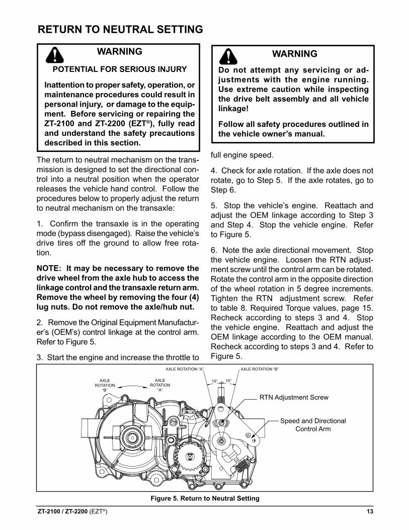
The return to neutral mechanism on the trans-mission is designed to set the directional con-trol into a neutral position when the operator releases the vehicle hand control. Follow the procedures below to properly adjust the return to neutral mechanism on the transaxle:
1. Confirm the transaxle is in the operating mode (bypass disengaged). Raise the vehicle’s drive tires off the ground to allow free rota-tion.
noTe: it may be necessary to remove the drive wheel from the axle hub to access the linkage control and the transaxle return arm. remove the wheel by removing the four (4) lug nuts. do not remove the axle/hub nut.
2. Remove the Original Equipment Manufactur-er’s (OEM’s) control linkage at the control arm. Refer to Figure 5.
3. Start the engine and increase the throttle to
full engine speed.
4. Check for axle rotation. If the axle does not rotate, go to Step 5. If the axle rotates, go to Step 6.
5. Stop the vehicle’s engine. Reattach and adjust the OEM linkage according to Step 3 and Step 4. Stop the vehicle engine. Refer to Figure 5.
6. Note the axle directional movement. Stop the vehicle engine. Loosen the RTN adjust-ment screw until the control arm can be rotated. Rotate the control arm in the opposite direction of the wheel rotation in 5 degree increments. Tighten the RTN adjustment screw. Refer to table 8. Required Torque values, page 15. Recheck according to steps 3 and 4. Stop the vehicle engine. Reattach and adjust the OEM linkage according to the OEM manual. Recheck according to steps 3 and 4. Refer to Figure 5.
figure 5. return to neutral setting
Speed and Directional Control Arm
RTN Adjustment Screw
15°15°
AXLE ROTATION “B”AXLE ROTATION “A”
AXLEROTATION
“A”
AXLEROTATION
“B”
14 ZT-2200 (EZT®)
ZT-2200 (eZT®) repair
How To use THis ManualEach subassembly illustrated in this section is illustrated with an exploded view showing the parts involved. The item reference numbers in each illustration are for assembly instruc-tions only. See page 33 for part names and descriptions. A complete exploded view and item list of the transaxle is provided at the end of the repair section.
general insTrucTionsCleanliness is a primary means of assuring satisfactory life on repaired units. Thoroughly clean all exposed surfaces prior to any type of maintenance. Cleaning of all parts by us-ing a solvent wash and air drying is usually adequate. As with any precision equipment, all parts must be kept free of foreign material and chemicals.
Protect all exposed sealing surfaces and open cavities from damage and foreign material. The external surfaces should be cleaned before beginning any repairs.
Upon removal, it is recommended that all seals, O-rings, and gaskets be replaced. During installation lightly lubricate all seals, O-rings and gaskets with a clean petroleum jelly prior to assembly. Also protect the inner diameter of seals by covering the shaft with a cellophane (plastic wrap, etc.) material.
Parts requiring replacement must be replaced from the appropriate kits identified in the Items Listing, found at the end of this manual. Use only original Hydro-Gear® replacement parts found at the Hydro-Gear website (www.hydro-gear.com).
iMporTanT: When internal repairs are per-formed on the hydraulic portion of the ZT-2200 (EZT®) , the filter assembly must be cleaned.
TransaXle reMovalIt is necessary to remove the transaxle from the vehicle before performing the repair procedures presented in this section.
noTe: if removing the wheel from the transaxle, do so by removing the four (4) lug nuts. do not remove the axle/hub nut.
liMiTed disasseMBlYThe following procedures are presented in the order in which they must be performed to completely disassemble the unit. Do not disas-semble the unit any farther than is necessary to accomplish the required repairs. Each disas-sembly procedure is followed by a correspond-ing assembly procedure.
Reassembly is accomplished by performing the “Assembly” portions of the procedures. If the unit has been completely disassembled, a summary of the assembly procedures, in the order in which they should occur, is given on page 30.
ZT-2200 (EZT®) 15
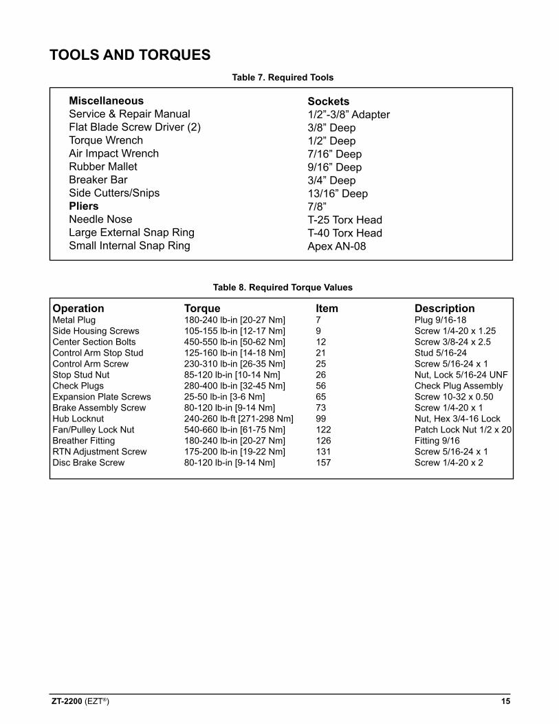
Table 7. required Tools
MiscellaneousService & Repair ManualFlat Blade Screw Driver (2)Torque WrenchAir Impact WrenchRubber MalletBreaker BarSide Cutters/SnipspliersNeedle NoseLarge External Snap RingSmall Internal Snap Ring
Tools and TorQues
sockets1/2”-3/8” Adapter3/8” Deep1/2” Deep7/16” Deep9/16” Deep3/4” Deep13/16” Deep7/8” T-25 Torx HeadT-40 Torx HeadApex AN-08
Table 8. required Torque values
operation Torque item description Metal Plug 180-240 lb-in [20-27 Nm] 7 Plug 9/16-18Side Housing Screws 105-155 lb-in [12-17 Nm] 9 Screw 1/4-20 x 1.25Center Section Bolts 450-550 lb-in [50-62 Nm] 12 Screw 3/8-24 x 2.5Control Arm Stop Stud 125-160 lb-in [14-18 Nm] 21 Stud 5/16-24 Control Arm Screw 230-310 lb-in [26-35 Nm] 25 Screw 5/16-24 x 1Stop Stud Nut 85-120 lb-in [10-14 Nm] 26 Nut, Lock 5/16-24 UNFCheck Plugs 280-400 lb-in [32-45 Nm] 56 Check Plug Assembly Expansion Plate Screws 25-50 lb-in [3-6 Nm] 65 Screw 10-32 x 0.50Brake Assembly Screw 80-120 lb-in [9-14 Nm] 73 Screw 1/4-20 x 1Hub Locknut 240-260 lb-ft [271-298 Nm] 99 Nut, Hex 3/4-16 LockFan/Pulley Lock Nut 540-660 lb-in [61-75 Nm] 122 Patch Lock Nut 1/2 x 20Breather Fitting 180-240 lb-in [20-27 Nm] 126 Fitting 9/16RTN Adjustment Screw 175-200 lb-in [19-22 Nm] 131 Screw 5/16-24 x 1Disc Brake Screw 80-120 lb-in [9-14 Nm] 157 Screw 1/4-20 x 2
16 ZT-2200 (EZT®)
wHeel HuB and nuT (code - a, c, f, or H)
EXAMPLE: Z H
Refer to Figure 6.
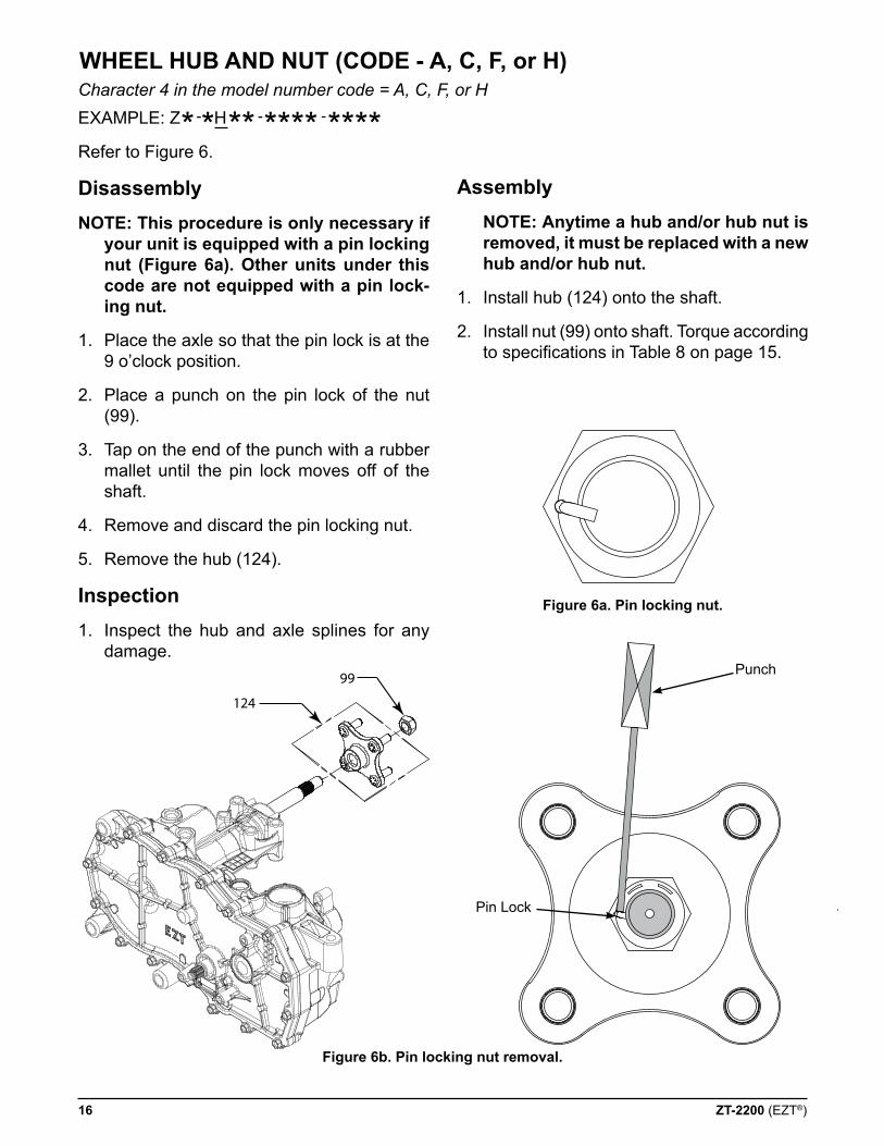
disassemblynoTe: This procedure is only necessary if
your unit is equipped with a pin locking nut (figure 6a). other units under this code are not equipped with a pin lock-ing nut.
1. Place the axle so that the pin lock is at the 9 o’clock position.
2. Place a punch on the pin lock of the nut (99).
3. Tap on the end of the punch with a rubber mallet until the pin lock moves off of the shaft.
4. Remove and discard the pin locking nut.
5. Remove the hub (124).
inspection
1. Inspect the hub and axle splines for any damage.
124
99
Pin Lock
Punch
assembly noTe: anytime a hub and/or hub nut is
removed, it must be replaced with a new hub and/or hub nut.
1. Install hub (124) onto the shaft.
2. Install nut (99) onto shaft. Torque according to specifications in Table 8 on page 15.
figure 6b. pin locking nut removal.
figure 6a. pin locking nut.
Character 4 in the model number code = A, C, F, or H
* * ** **** ****- - -
ZT-2200 (EZT®) 17
wHeel HuB and nuT (code - p, r, T, or u)
EXAMPLE: Z P
Refer to Figure 7.
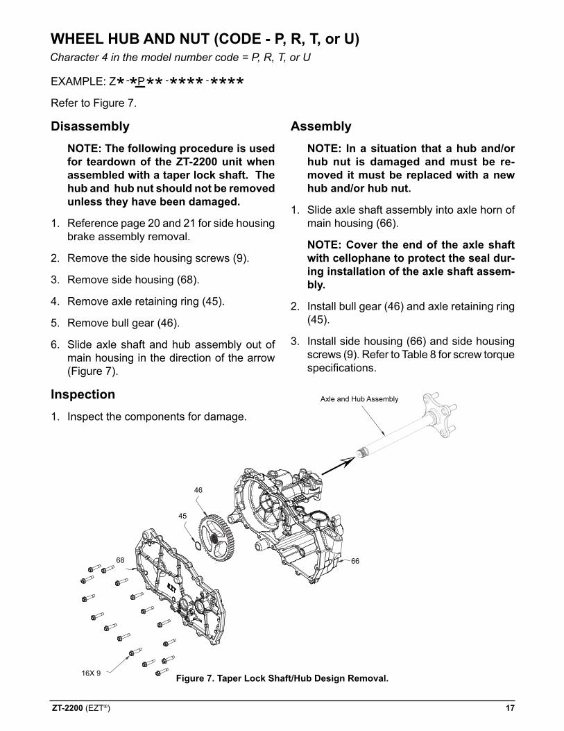
disassembly noTe: The following procedure is used
for teardown of the ZT-2200 unit when assembled with a taper lock shaft. The hub and hub nut should not be removed unless they have been damaged.
1. Reference page 20 and 21 for side housing brake assembly removal.
2. Remove the side housing screws (9).
3. Remove side housing (68).
4. Remove axle retaining ring (45).
5. Remove bull gear (46).
6. Slide axle shaft and hub assembly out of main housing in the direction of the arrow (Figure 7).
inspection
1. Inspect the components for damage.
assembly noTe: in a situation that a hub and/or
hub nut is damaged and must be re-moved it must be replaced with a new hub and/or hub nut.
1. Slide axle shaft assembly into axle horn of main housing (66).
noTe: cover the end of the axle shaft with cellophane to protect the seal dur-ing installation of the axle shaft assem-bly.
2. Install bull gear (46) and axle retaining ring (45).
3. Install side housing (66) and side housing screws (9). Refer to Table 8 for screw torque specifications.
Character 4 in the model number code = P, R, T, or U
* * ** **** ****- - -
figure 7. Taper lock shaft/Hub design removal.16X 9
45
68
46
Axle and Hub Assembly
66
18 ZT-2200 (EZT®)
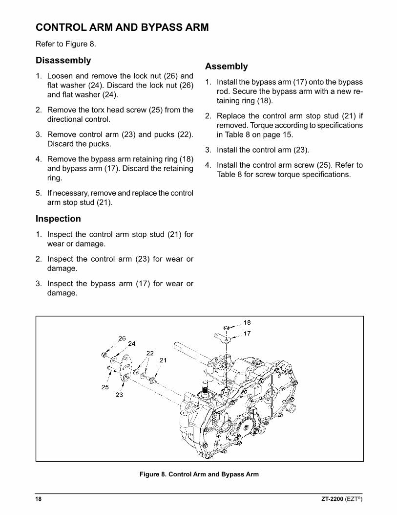
figure 8. control arm and Bypass arm
Refer to Figure 8.
disassembly1. Loosen and remove the lock nut (26) and
flat washer (24). Discard the lock nut (26) and flat washer (24).
2. Remove the torx head screw (25) from the directional control.
3. Remove control arm (23) and pucks (22). Discard the pucks.
4. Remove the bypass arm retaining ring (18) and bypass arm (17). Discard the retaining ring.
5. If necessary, remove and replace the control arm stop stud (21).
inspection
1. Inspect the control arm stop stud (21) for wear or damage.
2. Inspect the control arm (23) for wear or damage.
3. Inspect the bypass arm (17) for wear or damage.
assembly1. Install the bypass arm (17) onto the bypass
rod. Secure the bypass arm with a new re-taining ring (18).
2. Replace the control arm stop stud (21) if removed. Torque according to specifications in Table 8 on page 15.
3. Install the control arm (23).
4. Install the control arm screw (25). Refer to Table 8 for screw torque specifications.
conTrol arM and BYpass arM

ZT-2200 (EZT®) 19
figure 9. seal Kit replacement
Before disassembly, wipe the unit free of any debris to avoid contamination.
Refer to Figure 9.
input seal1. Remove the input pulley from the input
shaft.
2. Remove the seal retaining ring (34).
3. Carefully pull the input seal (33) out of the housing bore with a “hook” type tool. Care must be taken to avoid damage to the hous-ing bore or shaft sealing area.
4. Lubricate the new seal with petroleum jelly prior to installation.
5. Wrap the shaft keyway (splines) with cel-lophane to prevent damage to the seal lip during installation.
6. Slide the seal over the shaft and press it into the housing bore.
7. The seal should seat against the spacer.
8. Install the seal retaining ring (34) and make sure it is fully seated in its groove.
output seal1. The seal (51) can be replaced by following
steps 2-6 of the procedure used to replace the input seal.
2. Install the retaining ring (34) and make sure it is fully seated in its groove.
Motor shaft seal1. Remove the brake assembly. See pages
20-21.
2. The seal (10) can be replaced by following steps 3-6 of the procedure used to replace the input shaft.
Trunnion seal1. Remove the control arm and any attach-
ments to the control arm. See page 18.
2. The seal (20) can be replaced by following steps 3-6 of the procedure used to replace the input shaft.
Bypass seal1. Remove the bypass arm and any attach-
ments to the bypass arm. See page 18.
2. Remove the seal retaining ring (16). Re-move the bypass rod, keeping the retaining ring (14) attached. Remove the bypass rod seal (13). Deburr the bypass rod.
3. Install the seal (13). Install the bypass rod with the retaining ring (14) attached. Install the seal retaining ring (16).
seal KiT replaceMenT
20 ZT-2200 (EZT®)
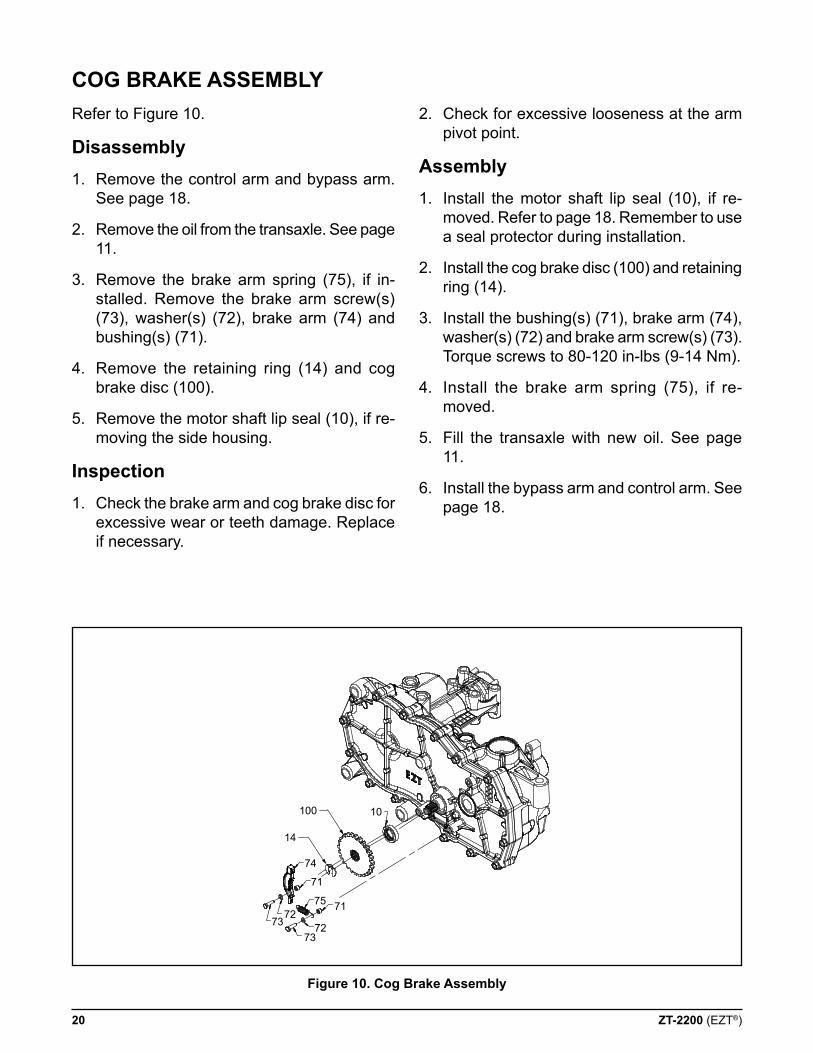
Refer to Figure 10.
disassembly1. Remove the control arm and bypass arm.
See page 18.
2. Remove the oil from the transaxle. See page 11.
3. Remove the brake arm spring (75), if in-stalled. Remove the brake arm screw(s) (73), washer(s) (72), brake arm (74) and bushing(s) (71).
4. Remove the retaining ring (14) and cog brake disc (100).
5. Remove the motor shaft lip seal (10), if re-moving the side housing.
inspection1. Check the brake arm and cog brake disc for
excessive wear or teeth damage. Replace if necessary.
figure 10. cog Brake assembly
2. Check for excessive looseness at the arm pivot point.
assembly1. Install the motor shaft lip seal (10), if re-
moved. Refer to page 18. Remember to use a seal protector during installation.
2. Install the cog brake disc (100) and retaining ring (14).
3. Install the bushing(s) (71), brake arm (74), washer(s) (72) and brake arm screw(s) (73). Torque screws to 80-120 in-lbs (9-14 Nm).
4. Install the brake arm spring (75), if re-moved.
5. Fill the transaxle with new oil. See page 11.
6. Install the bypass arm and control arm. See page 18.
cog BraKe asseMBlY
7373
7271
72
71
75
74
14
100 10
ZT-2200 (EZT®) 21
disc BraKe asseMBlY
160
159
158
74
75
157
156
2X 155
73
154153
151
2X 150
100
153
10
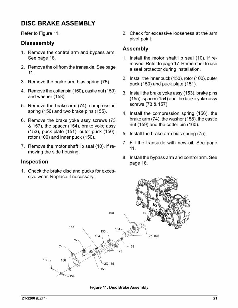
figure 11. disc Brake assembly
Refer to Figure 11.
disassembly1. Remove the control arm and bypass arm.
See page 18.
2. Remove the oil from the transaxle. See page 11.
3. Remove the brake arm bias spring (75).
4. Remove the cotter pin (160), castle nut (159) and washer (158).
5. Remove the brake arm (74), compression spring (156) and two brake pins (155).
6. Remove the brake yoke assy screws (73 & 157), the spacer (154), brake yoke assy (153), puck plate (151), outer puck (150), rotor (100) and inner puck (150).
7. Remove the motor shaft lip seal (10), if re-moving the side housing.
inspection1. Check the brake disc and pucks for exces-
sive wear. Replace if necessary.
2. Check for excessive looseness at the arm pivot point.
assembly1. Install the motor shaft lip seal (10), if re-
moved. Refer to page 17. Remember to use a seal protector during installation.
2. Install the inner puck (150), rotor (100), outer puck (150) and puck plate (151).
3. Install the brake yoke assy (153), brake pins (155), spacer (154) and the brake yoke assy screws (73 & 157).
4. Install the compression spring (156), the brake arm (74), the washer (158), the castle nut (159) and the cotter pin (160).
5. Install the brake arm bias spring (75).
7. Fill the transaxle with new oil. See page 11.
8. Install the bypass arm and control arm. See page 18.
22 ZT-2200 (EZT®)
1
23
4
5
6
7
8
9
10
11
12
13
14
15
16
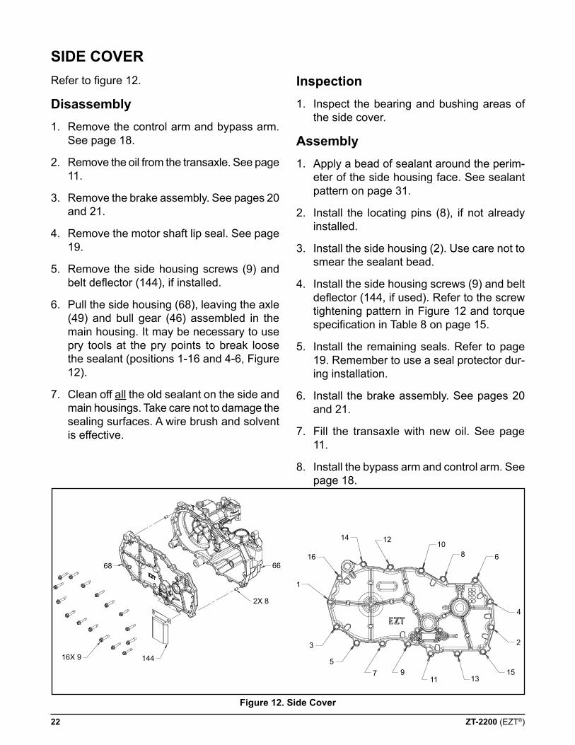
Refer to figure 12.
disassembly1. Remove the control arm and bypass arm.
See page 18.
2. Remove the oil from the transaxle. See page 11.
3. Remove the brake assembly. See pages 20 and 21.
4. Remove the motor shaft lip seal. See page 19.
5. Remove the side housing screws (9) and belt deflector (144), if installed.
6. Pull the side housing (68), leaving the axle (49) and bull gear (46) assembled in the main housing. It may be necessary to use pry tools at the pry points to break loose the sealant (positions 1-16 and 4-6, Figure 12).
7. Clean off all the old sealant on the side and main housings. Take care not to damage the sealing surfaces. A wire brush and solvent is effective.
side coverinspection1. Inspect the bearing and bushing areas of
the side cover.
assembly1. Apply a bead of sealant around the perim-
eter of the side housing face. See sealant pattern on page 31.
2. Install the locating pins (8), if not already installed.
3. Install the side housing (2). Use care not to smear the sealant bead.
4. Install the side housing screws (9) and belt deflector (144, if used). Refer to the screw tightening pattern in Figure 12 and torque specification in Table 8 on page 15.
5. Install the remaining seals. Refer to page 19. Remember to use a seal protector dur-ing installation.
6. Install the brake assembly. See pages 20 and 21.
7. Fill the transaxle with new oil. See page 11.
8. Install the bypass arm and control arm. See page 18.
16X 9 144
2X 8
6668
figure 12. side cover
ZT-2200 (EZT®) 23
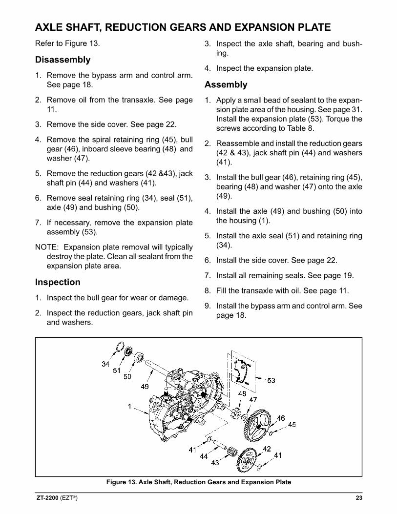
Refer to Figure 13.
disassembly1. Remove the bypass arm and control arm.
See page 18.
2. Remove oil from the transaxle. See page 11.
3. Remove the side cover. See page 22.
4. Remove the spiral retaining ring (45), bull gear (46), inboard sleeve bearing (48) and washer (47).
5. Remove the reduction gears (42 &43), jack shaft pin (44) and washers (41).
6. Remove seal retaining ring (34), seal (51), axle (49) and bushing (50).
7. If necessary, remove the expansion plate assembly (53).
NOTE: Expansion plate removal will typically destroy the plate. Clean all sealant from the expansion plate area.
inspection1. Inspect the bull gear for wear or damage.
2. Inspect the reduction gears, jack shaft pin and washers.
figure 13. axle shaft, reduction gears and expansion plate
3. Inspect the axle shaft, bearing and bush-ing.
4. Inspect the expansion plate.
assembly1. Apply a small bead of sealant to the expan-
sion plate area of the housing. See page 31. Install the expansion plate (53). Torque the screws according to Table 8.
2. Reassemble and install the reduction gears (42 & 43), jack shaft pin (44) and washers (41).
3. Install the bull gear (46), retaining ring (45), bearing (48) and washer (47) onto the axle (49).
4. Install the axle (49) and bushing (50) into the housing (1).
5. Install the axle seal (51) and retaining ring (34).
6. Install the side cover. See page 22.
7. Install all remaining seals. See page 19.
8. Fill the transaxle with oil. See page 11.
9. Install the bypass arm and control arm. See page 18.
aXle sHafT, reducTion gears and eXpansion plaTe
24 ZT-2200 (EZT®)
figure 14. Motor shaft
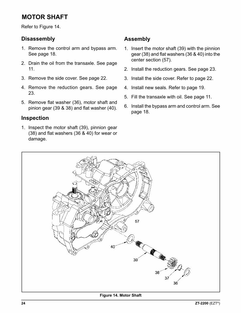
Refer to Figure 14.
disassembly1. Remove the control arm and bypass arm.
See page 18.
2. Drain the oil from the transaxle. See page 11.
3. Remove the side cover. See page 22.
4. Remove the reduction gears. See page 23.
5. Remove flat washer (36), motor shaft and pinion gear (39 & 38) and flat washer (40).
inspection1. Inspect the motor shaft (39), pinnion gear
(38) and flat washers (36 & 40) for wear or damage.
assembly1. Insert the motor shaft (39) with the pinnion
gear (38) and flat washers (36 & 40) into the center section (57).
2. Install the reduction gears. See page 23.
3. Install the side cover. Refer to page 22.
4. Install new seals. Refer to page 19.
5. Fill the transaxle with oil. See page 11.
6. Install the bypass arm and control arm. See page 18.
MoTor sHafT
ZT-2200 (EZT®) 25
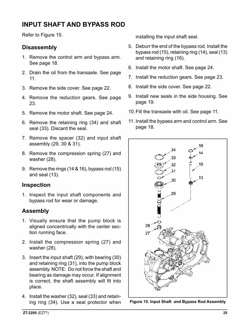
figure 15. input shaft and Bypass rod assembly
Refer to Figure 15.
disassembly1. Remove the control arm and bypass arm.
See page 18.
2. Drain the oil from the transaxle. See page 11.
3. Remove the side cover. See page 22.
4. Remove the reduction gears. See page 23.
5. Remove the motor shaft. See page 24.
6. Remove the retaining ring (34) and shaft seal (33). Discard the seal.
7. Remove the spacer (32) and input shaft assembly (29, 30 & 31).
8. Remove the compression spring (27) and washer (28).
9. Remove the rings (14 & 16), bypass rod (15) and seal (13).
inspection1. Inspect the input shaft components and
bypass rod for wear or damage.
assembly1. Visually ensure that the pump block is
aligned concentrically with the center sec-tion running face.
2. Install the compression spring (27) and washer (28).
3. Insert the input shaft (29), with bearing (30) and retaining ring (31), into the pump block assembly. NOTE: Do not force the shaft and bearing as damage may occur. If alignment is correct, the shaft assembly will fit into place.
4. Install the washer (32), seal (33) and retain-ing ring (34). Use a seal protector when
installing the input shaft seal.
5. Deburr the end of the bypass rod. Install the bypass rod (15), retaining ring (14), seal (13) and retaining ring (16).
6. Install the motor shaft. See page 24.
7. Install the reduction gears. See page 23.
8. Install the side cover. See page 22.
9. Install new seals in the side housing. See page 19.
10. Fill the transaxle with oil. See page 11.
11. Install the bypass arm and control arm. See page 18.
inpuT sHafT and BYpass rod
26 ZT-2200 (EZT®)
Refer to Figures 16-25.
disassembly1. Remove the bypass arm and control arm.
See page 18.
2. Drain the oil from the transaxle. See page 11.
3. Remove the side cover. See page 22.
4. Remove the reduction gears. See page 23.
5. Remove the motor shaft. See page 24.
6. Remove the input shaft and bypass rod. See page 25.
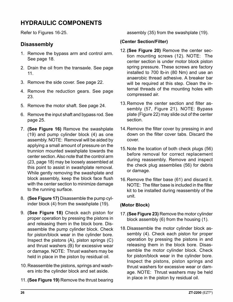
7. (see figure 16) Remove the swashplate (19) and pump cylinder block (4) as one assembly. NOTE: Removal will be aided by applying a small amount of pressure on the trunnion mounted swashplate towards the center section. Also note that the control arm (23, page 18) may be loosely assembled at this point to assist in swashplate removal. While gently removing the swashplate and block assembly, keep the block face flush with the center section to minimize damage to the running surface.
8. (see figure 17) Disassemble the pump cyl-inder block (4) from the swashplate (19).
9. (see figure 18) Check each piston for proper operation by pressing the pistons in and releasing them in the block bore. Dis-assemble the pump cylinder block. Check for piston/block wear in the cylinder bore. Inspect the pistons (A), piston springs (C) and thrust washers (B) for excessive wear or damage. NOTE: Thrust washers may be held in place in the piston by residual oil.
10. Reassemble the pistons, springs and wash-ers into the cylinder block and set aside.
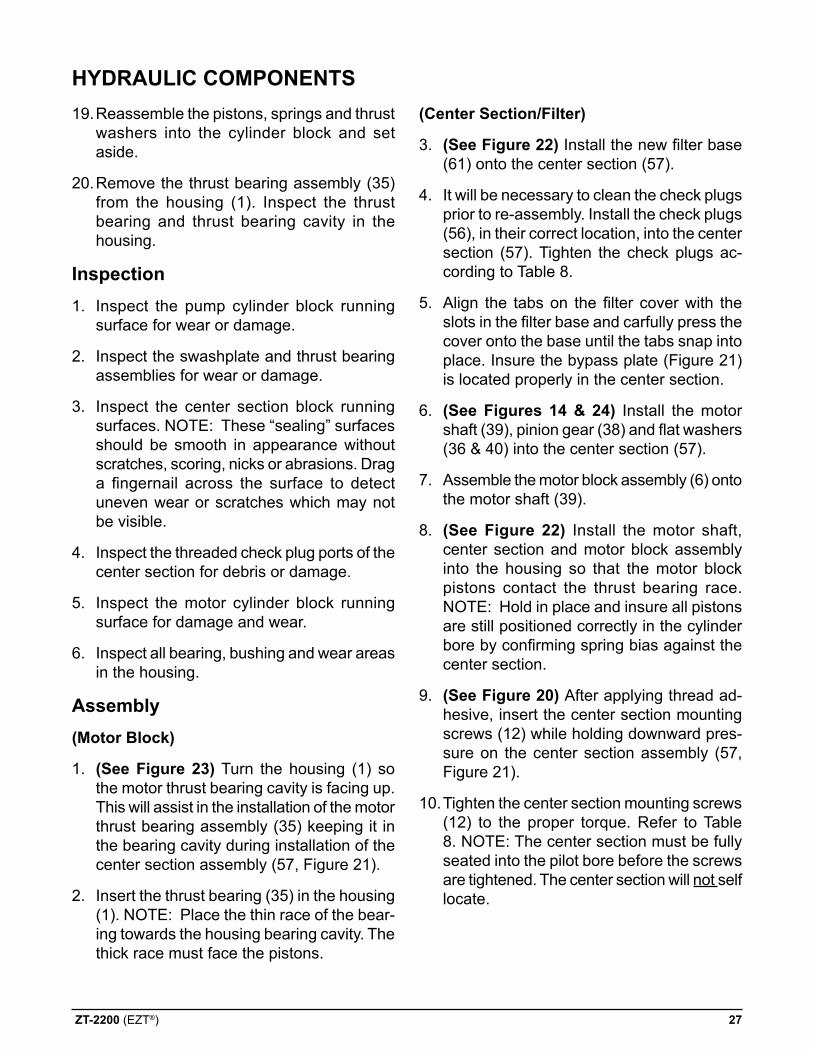
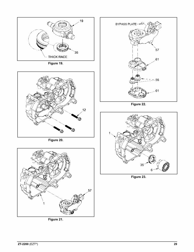
11. (see figure 19) Remove the thrust bearing
assembly (35) from the swashplate (19).
(center section/filter)
12. (see figure 20) Remove the center sec-tion mounting screws (12). NOTE: The center section is under motor block piston spring pressure. These screws are factory installed to 700 lb-in (80 Nm) and use an anaerobic thread adhesive. A breaker bar will be required at this step. Clean the in-ternal threads of the mounting holes with compressed air.
13. Remove the center section and filter as-sembly (57, Figure 21). NOTE: Bypass plate (Figure 22) may slide out of the center section.
14. Remove the filter cover by pressing in and down on the filter cover tabs. Discard the cover.
15. Note the location of both check plugs (56) before removal for correct replacement during reassembly. Remove and inspect the check plug assemblies (56) for debris or damage.
16. Remove the filter base (61) and discard it. NOTE: The filter base is included in the filter kit to be installed during reassembly of the unit.
(Motor Block)
17. (see figure 23) Remove the motor cylinder block assembly (6) from the housing (1).
18. Disassemble the motor cylinder block as-sembly (4). Check each piston for proper operation by pressing the pistons in and releasing them in the block bore. Disas-semble the motor cylinder block. Check for piston/block wear in the cylinder bore. Inspect the pistons, piston springs and thrust washers for excessive wear or dam-age. NOTE: Thrust washers may be held in place in the piston by residual oil.
HYdraulic coMponenTs
ZT-2200 (EZT®) 27
19. Reassemble the pistons, springs and thrust
washers into the cylinder block and set aside.
20. Remove the thrust bearing assembly (35) from the housing (1). Inspect the thrust bearing and thrust bearing cavity in the housing.
inspection1. Inspect the pump cylinder block running
surface for wear or damage.
2. Inspect the swashplate and thrust bearing assemblies for wear or damage.
3. Inspect the center section block running surfaces. NOTE: These “sealing” surfaces should be smooth in appearance without scratches, scoring, nicks or abrasions. Drag a fingernail across the surface to detect uneven wear or scratches which may not be visible.
4. Inspect the threaded check plug ports of the center section for debris or damage.
5. Inspect the motor cylinder block running surface for damage and wear.
6. Inspect all bearing, bushing and wear areas in the housing.
assembly(Motor Block)
1. (see figure 23) Turn the housing (1) so the motor thrust bearing cavity is facing up. This will assist in the installation of the motor thrust bearing assembly (35) keeping it in the bearing cavity during installation of the center section assembly (57, Figure 21).
2. Insert the thrust bearing (35) in the housing (1). NOTE: Place the thin race of the bear-ing towards the housing bearing cavity. The thick race must face the pistons.
(center section/filter)
3. (see figure 22) Install the new filter base (61) onto the center section (57).
4. It will be necessary to clean the check plugs prior to re-assembly. Install the check plugs (56), in their correct location, into the center section (57). Tighten the check plugs ac-cording to Table 8.
5. Align the tabs on the filter cover with the slots in the filter base and carfully press the cover onto the base until the tabs snap into place. Insure the bypass plate (Figure 21) is located properly in the center section.
6. (see figures 14 & 24) Install the motor shaft (39), pinion gear (38) and flat washers (36 & 40) into the center section (57).
7. Assemble the motor block assembly (6) onto the motor shaft (39).
8. (see figure 22) Install the motor shaft, center section and motor block assembly into the housing so that the motor block pistons contact the thrust bearing race. NOTE: Hold in place and insure all pistons are still positioned correctly in the cylinder bore by confirming spring bias against the center section.
9. (see figure 20) After applying thread ad-hesive, insert the center section mounting screws (12) while holding downward pres-sure on the center section assembly (57, Figure 21).
10. Tighten the center section mounting screws (12) to the proper torque. Refer to Table 8. NOTE: The center section must be fully seated into the pilot bore before the screws are tightened. The center section will not self locate.
HYdraulic coMponenTs
28 ZT-2200 (EZT®)
(swashplate/pump Block)
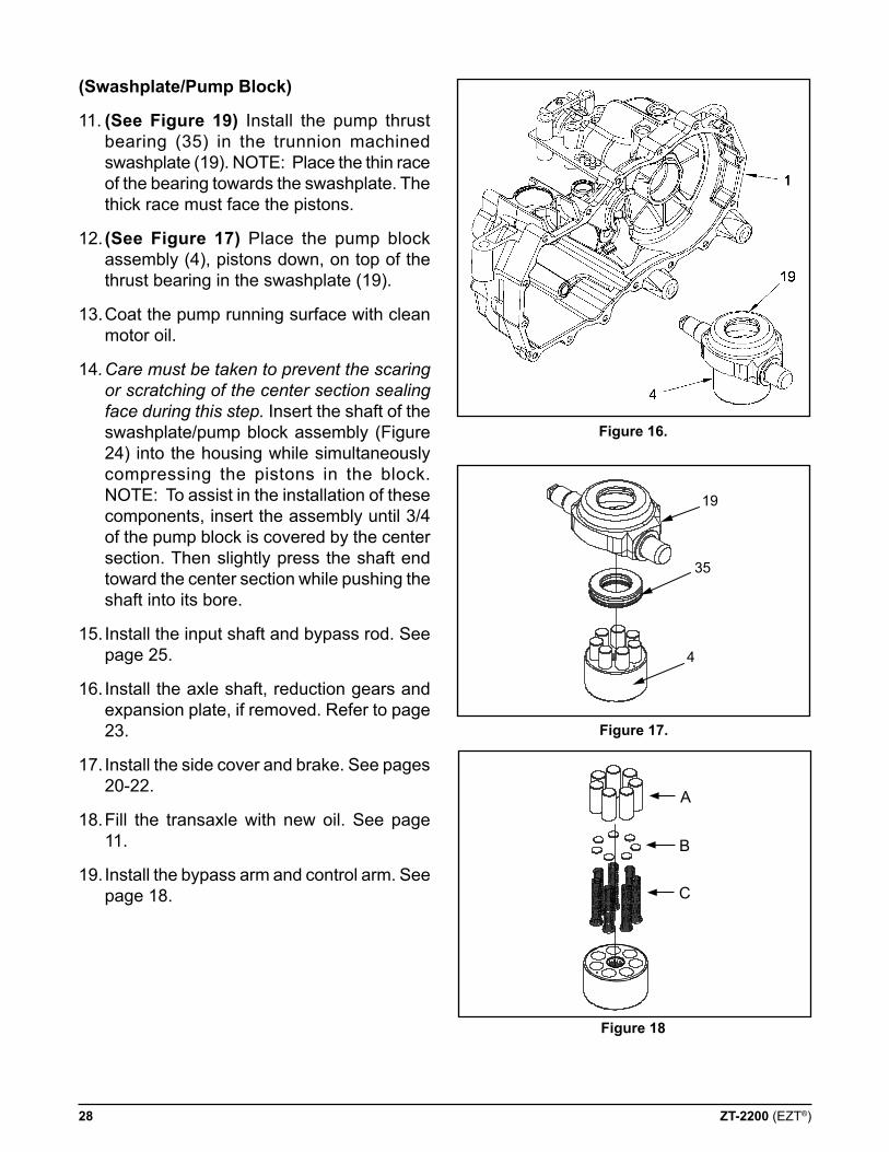
11. (see figure 19) Install the pump thrust bearing (35) in the trunnion machined swashplate (19). NOTE: Place the thin race of the bearing towards the swashplate. The thick race must face the pistons.
12. (see figure 17) Place the pump block assembly (4), pistons down, on top of the thrust bearing in the swashplate (19).
13. Coat the pump running surface with clean motor oil.
14. Care must be taken to prevent the scaring or scratching of the center section sealing face during this step. Insert the shaft of the swashplate/pump block assembly (Figure 24) into the housing while simultaneously compressing the pistons in the block. NOTE: To assist in the installation of these components, insert the assembly until 3/4 of the pump block is covered by the center section. Then slightly press the shaft end toward the center section while pushing the shaft into its bore.
15. Install the input shaft and bypass rod. See page 25.
16. Install the axle shaft, reduction gears and expansion plate, if removed. Refer to page 23.
17. Install the side cover and brake. See pages 20-22.
18. Fill the transaxle with new oil. See page 11.
19. Install the bypass arm and control arm. See page 18.
figure 16.
figure 17.
figure 18
19
35
4
A
B
C
ZT-2200 (EZT®) 29
figure 19.
figure 20.
figure 21.
figure 22.
figure 23.
356
1
30 ZT-2200 (EZT®)
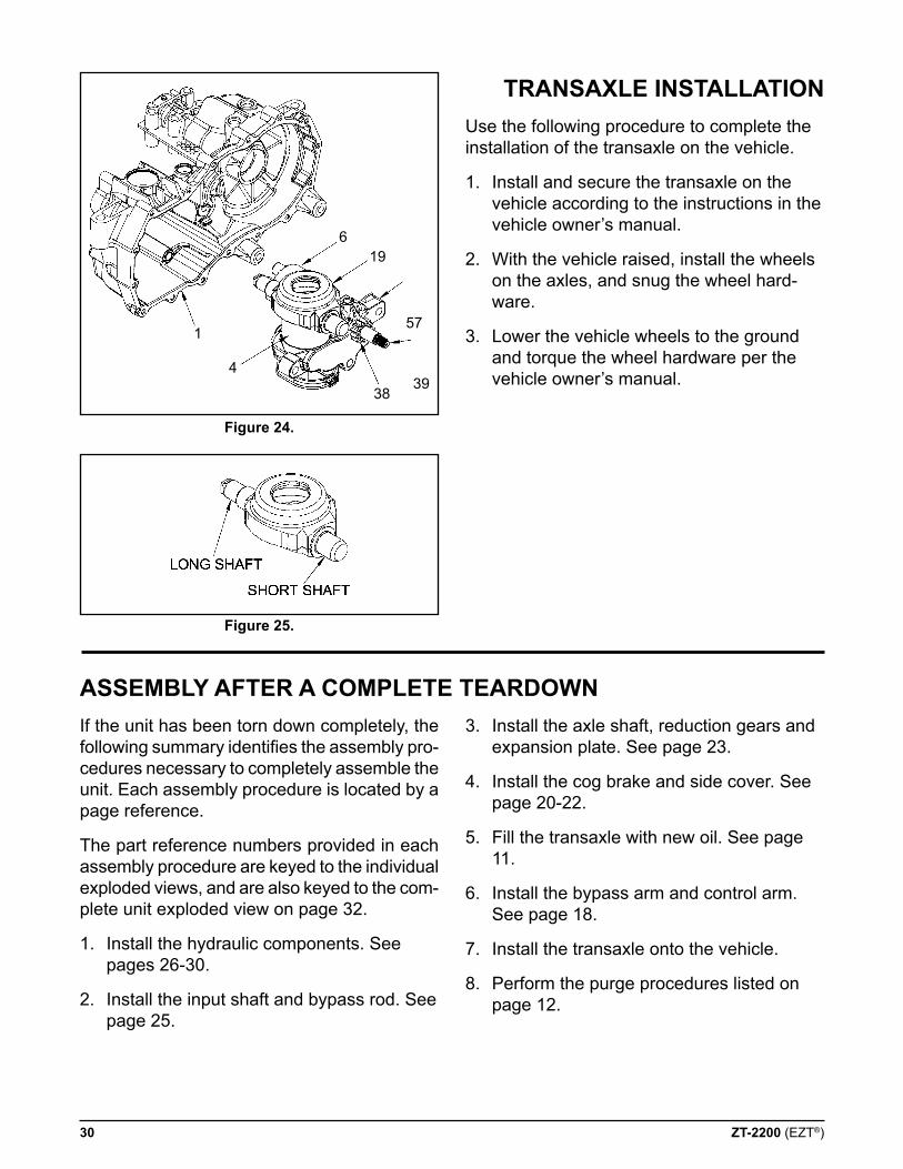
figure 24.
Use the following procedure to complete the installation of the transaxle on the vehicle.
1. Install and secure the transaxle on the vehicle according to the instructions in the vehicle owner’s manual.
2. With the vehicle raised, install the wheels on the axles, and snug the wheel hard-ware.
3. Lower the vehicle wheels to the ground and torque the wheel hardware per the vehicle owner’s manual.
figure 25.
TransaXle insTallaTion
1
4
3839
57
196
If the unit has been torn down completely, the following summary identifies the assembly pro-cedures necessary to completely assemble the unit. Each assembly procedure is located by a page reference.
The part reference numbers provided in each assembly procedure are keyed to the individual exploded views, and are also keyed to the com-plete unit exploded view on page 32.
1. Install the hydraulic components. See pages 26-30.
2. Install the input shaft and bypass rod. See page 25.
3. Install the axle shaft, reduction gears and expansion plate. See page 23.
4. Install the cog brake and side cover. See page 20-22.
5. Fill the transaxle with new oil. See page 11.
6. Install the bypass arm and control arm. See page 18.
7. Install the transaxle onto the vehicle.
8. Perform the purge procedures listed on page 12.
asseMBlY afTer a coMpleTe Teardown
ZT-2200 (EZT®) 31
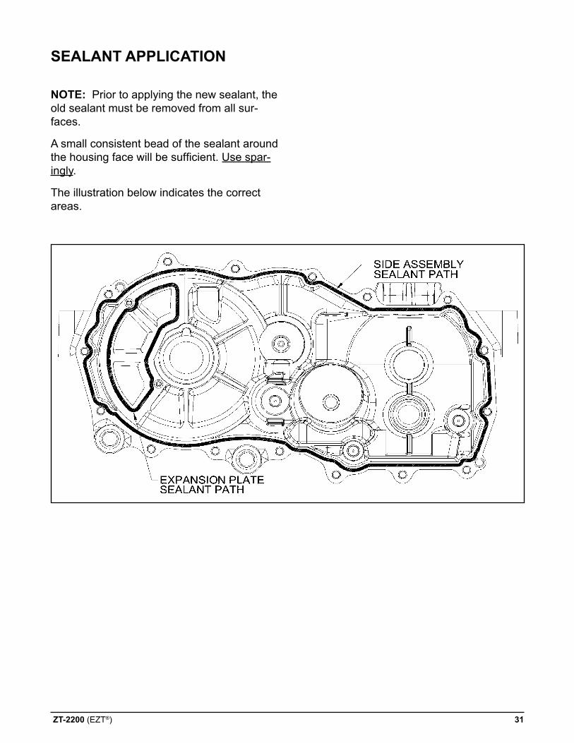
noTe: Prior to applying the new sealant, the old sealant must be removed from all sur-faces.
A small consistent bead of the sealant around the housing face will be sufficient. Use spar-ingly.
The illustration below indicates the correct areas.
sealanT applicaTion
32 ZT-2200 (EZT®)
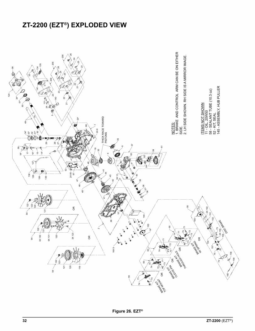
figure 26. eZT®
ZT-2200 (eZT®) eXploded view
NO
TES
: 1.
BR
AK
E A
ND
CO
NTR
OL
AR
M C
AN
BE
ON
EIT
HE
R
SID
E.
2. L
H S
IDE
SH
OW
N. R
H S
IDE
IS A
MIR
RO
R IM
AG
E.
ITE
MS
NO
T S
HO
WN
11
- O
IL, 2
0W50
58
- S
EA
LAN
T TU
BE
(10.
3 oz
) 52
- K
IT, S
EA
L 14
5 - A
SS
EM
BLY
, HU
B P
ULL
ER
159
158
160
74
7515
7
156
154
732X
155
153
1512X
150
100
55
DISC
BRA
KE
BRAK
E KI
T
W/ S
PRIN
G OR
100
14*
144
36
55
71
7175
74
7272
72
7373
73
71
55
55
74
70
71
7274
73
73
7471
55
BRAK
E KI
T
THRO
UGH
HOLE
BRAK
E KI
T
CLEV
IS P
IN
BRAK
E KI
T
TOP
MO
UNT
OR
OR
OR
37*38
3940
6462
63
3
56
6061
57
35
6
4
3519
2
16X
968
10*
4144
4342
3X 1
2
41
45*
4647
48
672X
65
THIC
K R
AC
E T
OW
AR
D
PIS
TON
S2X 8
1
20*
66
53
13*29 28 27
7
3031*
3234*
33*
4950
51*
34*12
4
99
25
5918
* 17 16*
15 14*
127
138
128
126
139
54
54
54
122
122
122
123
123
120
120
120
121
119
121
121
3X 1
30
6X 1
31
3X 1
23
OR
OR
OR
200
200
200
26
2624
24
24
135
134
141
23
131
140
5
22
22
21
21
23
23
25
25
ZT-2200 (EZT®) 33
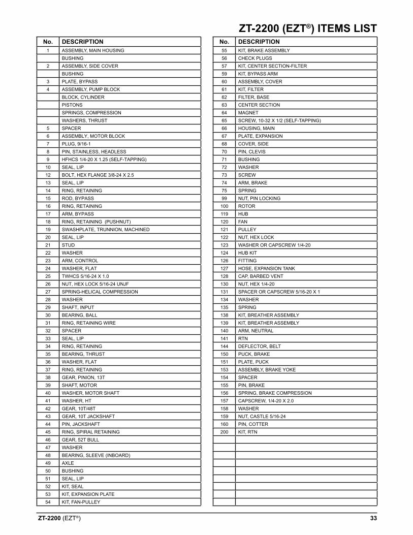
ZT-2200 (eZT®) iTeMs lisTno. descripTion
1 ASSEMBLY, MAIN HOUSINGBUSHING
2 ASSEMBLY, SIDE COVERBUSHING
3 PLATE, BYPASS4 ASSEMBLY, PUMP BLOCK
BLOCK, CYLINDERPISTONSSPRINGS, COMPRESSIONWASHERS, THRUST
5 SPACER6 ASSEMBLY, MOTOR BLOCK7 PLUG, 9/16-18 PIN, STAINLESS, HEADLESS9 HFHCS 1/4-20 X 1.25 (SELF-TAPPING)
10 SEAL, LIP12 BOLT, HEX FLANGE 3/8-24 X 2.513 SEAL, LIP14 RING, RETAINING15 ROD, BYPASS16 RING, RETAINING17 ARM, BYPASS18 RING, RETAINING (PUSHNUT)19 SWASHPLATE, TRUNNION, MACHINED20 SEAL, LIP21 STUD22 WASHER23 ARM, CONTROL24 WASHER, FLAT25 TWHCS 5/16-24 X 1.026 NUT, HEX LOCK 5/16-24 UNJF27 SPRING-HELICAL COMPRESSION28 WASHER29 SHAFT, INPUT30 BEARING, BALL31 RING, RETAINING WIRE32 SPACER33 SEAL, LIP34 RING, RETAINING35 BEARING, THRUST36 WASHER, FLAT37 RING, RETAINING38 GEAR, PINION, 13T39 SHAFT, MOTOR40 WASHER, MOTOR SHAFT41 WASHER, HT42 GEAR, 10T/48T43 GEAR, 10T JACKSHAFT44 PIN, JACKSHAFT45 RING, SPIRAL RETAINING46 GEAR, 52T BULL47 WASHER48 BEARING, SLEEVE (INBOARD)49 AXLE50 BUSHING51 SEAL, LIP52 KIT, SEAL53 KIT, EXPANSION PLATE54 KIT, FAN-PULLEY
no. descripTion55 KIT, BRAKE ASSEMBLY56 CHECK PLUGS57 KIT, CENTER SECTION-FILTER59 KIT, BYPASS ARM60 ASSEMBLY, COVER61 KIT, FILTER62 FILTER, BASE63 CENTER SECTION64 MAGNET65 SCREW, 10-32 X 1/2 (SELF-TAPPING)66 HOUSING, MAIN67 PLATE, EXPANSION68 COVER, SIDE70 PIN, CLEVIS71 BUSHING72 WASHER73 SCREW74 ARM, BRAKE75 SPRING99 NUT, PIN LOCKING100 ROTOR119 HUB120 FAN121 PULLEY122 NUT, HEX LOCK123 WASHER OR CAPSCREW 1/4-20124 HUB KIT126 FITTING127 HOSE, EXPANSION TANK128 CAP, BARBED VENT130 NUT, HEX 1/4-20131 SPACER OR CAPSCREW 5/16-20 X 1134 WASHER135 SPRING138 KIT, BREATHER ASSEMBLY139 KIT, BREATHER ASSEMBLY140 ARM, NEUTRAL141 RTN144 DEFLECTOR, BELT150 PUCK, BRAKE151 PLATE, PUCK153 ASSEMBLY, BRAKE YOKE154 SPACER155 PIN, BRAKE156 SPRING, BRAKE COMPRESSION157 CAPSCREW, 1/4-20 X 2.0158 WASHER159 NUT, CASTLE 5/16-24160 PIN, COTTER200 KIT, RTN

34 ZT-2100
ZT-2100 35
ZT-2100 RepaiR
HOW TO USe THiS MaNUaLEach subassembly illustrated in this section is illustrated with an exploded view showing the parts involved. The item reference numbers in each illustration are for assembly instruc-tions only. See page 55 for part names and descriptions. A complete exploded view and item list of the transaxle is provided at the end of the repair section.
GeNeRaL iNSTRUCTiONSCleanliness is a primary means of assuring satisfactory life on repaired units. Thoroughly clean all exposed surfaces prior to any type of maintenance. Cleaning of all parts by us-ing a solvent wash and air drying is usually adequate. As with any precision equipment, all parts must be kept free of foreign material and chemicals.
Protect all exposed sealing surfaces and open cavities from damage and foreign material. The external surfaces should be cleaned before beginning any repairs.
Upon removal, it is recommended that all seals, O-rings, and gaskets be replaced. During installation lightly lubricate all seals, O-rings and gaskets with a clean petroleum jelly prior to assembly. Also protect the inner diameter of seals by covering the shaft with a cellophane (plastic wrap, etc.) material.
Parts requiring replacement must be replaced from the appropriate kits identified in the Items Listing, found at the end of this manual. Use only original Hydro-Gear® replacement parts found in on the Hydro-Gear website. (www.hydro-gear.com)
iMpORTaNT: When internal repairs are per-formed on the hydraulic portion of the ZT-2100, the filter assembly must be cleaned.
TRaNSaXLe ReMOVaLIt is necessary to remove the ZT-2100 from the vehicle before performing the repair procedures presented in this section.
NOTe: if removing the wheel from the transaxle, do so by removing the four (4) lug nuts. Do not remove the axle/hub nut.
LiMiTeD DiSaSSeMBLYThe following procedures are presented in the order in which they must be performed to completely disassemble the unit. Do not disas-semble the unit any farther than is necessary to accomplish the required repairs. Each disas-sembly procedure is followed by a correspond-ing assembly procedure.
Reassembly is accomplished by performing the “Assembly” portions of the procedures. If the unit has been completely disassembled, a summary of the assembly procedures, in the order in which they should occur, is given on page 51.
36 ZT-2100
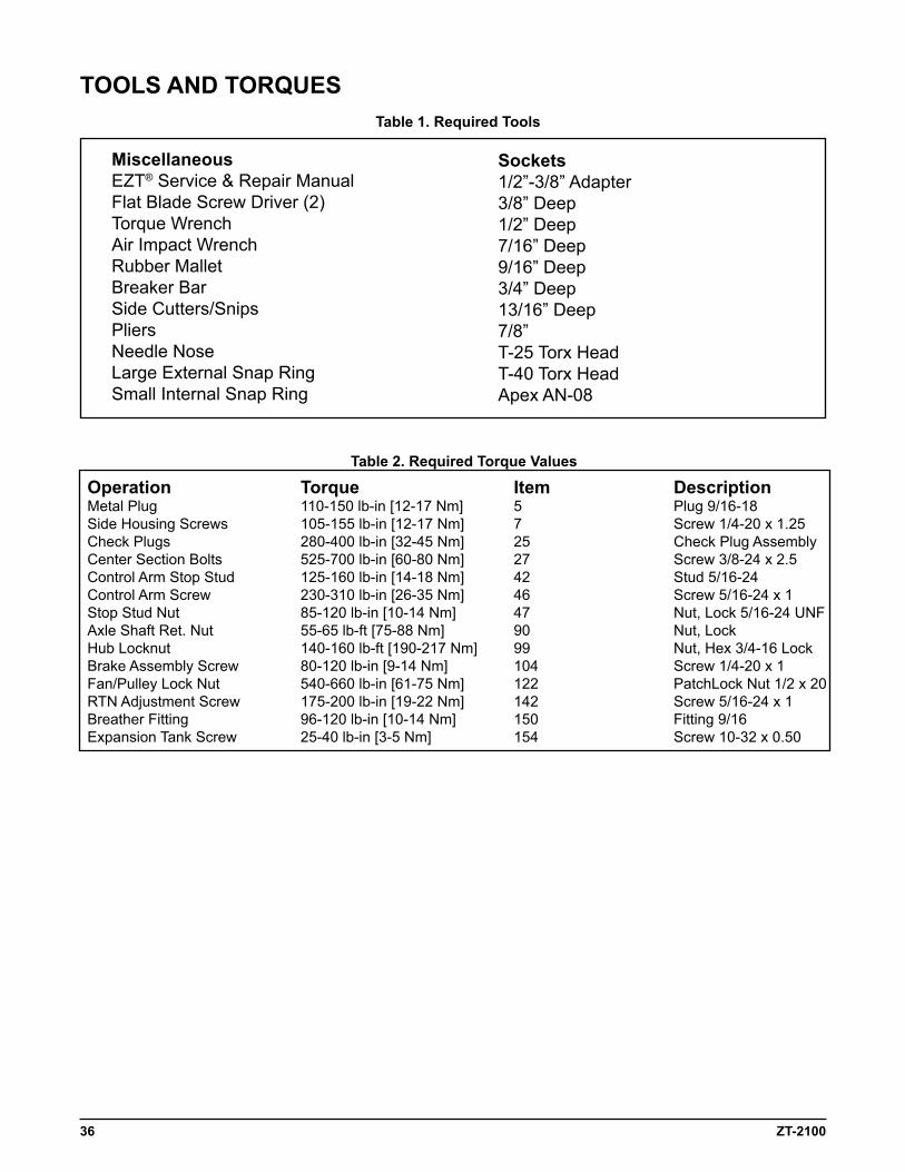
Table 1. Required Tools
MiscellaneousEZT® Service & Repair ManualFlat Blade Screw Driver (2)Torque WrenchAir Impact WrenchRubber MalletBreaker BarSide Cutters/SnipsPliersNeedle NoseLarge External Snap RingSmall Internal Snap Ring
TOOLS aND TORQUeS
Sockets1/2”-3/8” Adapter3/8” Deep1/2” Deep7/16” Deep9/16” Deep3/4” Deep13/16” Deep7/8” T-25 Torx HeadT-40 Torx HeadApex AN-08
Table 2. Required Torque Values
Operation Torque item Description Metal Plug 110-150 lb-in [12-17 Nm] 5 Plug 9/16-18Side Housing Screws 105-155 lb-in [12-17 Nm] 7 Screw 1/4-20 x 1.25Check Plugs 280-400 lb-in [32-45 Nm] 25 Check Plug AssemblyCenter Section Bolts 525-700 lb-in [60-80 Nm] 27 Screw 3/8-24 x 2.5Control Arm Stop Stud 125-160 lb-in [14-18 Nm] 42 Stud 5/16-24 Control Arm Screw 230-310 lb-in [26-35 Nm] 46 Screw 5/16-24 x 1Stop Stud Nut 85-120 lb-in [10-14 Nm] 47 Nut, Lock 5/16-24 UNFAxle Shaft Ret. Nut 55-65 lb-ft [75-88 Nm] 90 Nut, LockHub Locknut 140-160 lb-ft [190-217 Nm] 99 Nut, Hex 3/4-16 LockBrake Assembly Screw 80-120 lb-in [9-14 Nm] 104 Screw 1/4-20 x 1Fan/Pulley Lock Nut 540-660 lb-in [61-75 Nm] 122 PatchLock Nut 1/2 x 20RTN Adjustment Screw 175-200 lb-in [19-22 Nm] 142 Screw 5/16-24 x 1Breather Fitting 96-120 lb-in [10-14 Nm] 150 Fitting 9/16Expansion Tank Screw 25-40 lb-in [3-5 Nm] 154 Screw 10-32 x 0.50
ZT-2100 37
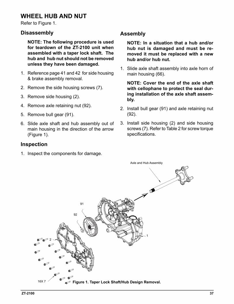
WHeeL HUB aND NUT Refer to Figure 1.
Disassembly NOTe: The following procedure is used
for teardown of the ZT-2100 unit when assembled with a taper lock shaft. The hub and hub nut should not be removed unless they have been damaged.
1. Reference page 41 and 42 for side housing & brake assembly removal.
2. Remove the side housing screws (7).
3. Remove side housing (2).
4. Remove axle retaining nut (92).
5. Remove bull gear (91).
6. Slide axle shaft and hub assembly out of main housing in the direction of the arrow (Figure 1).
inspection
1. Inspect the components for damage.
assembly NOTe: in a situation that a hub and/or
hub nut is damaged and must be re-moved it must be replaced with a new hub and/or hub nut.
1. Slide axle shaft assembly into axle horn of main housing (66).
NOTe: Cover the end of the axle shaft with cellophane to protect the seal dur-ing installation of the axle shaft assem-bly.
2. Install bull gear (91) and axle retaining nut (92).
3. Install side housing (2) and side housing screws (7). Refer to Table 2 for screw torque specifications.
Figure 1. Taper Lock Shaft/Hub Design Removal.16X 7
92
2
91
Axle and Hub Assembly
1
38 ZT-2100
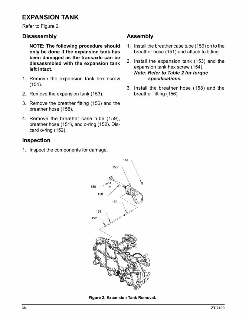
eXpaNSiON TaNKRefer to Figure 2.
Disassembly NOTe: The following procedure should
only be done if the expansion tank has been damaged as the transaxle can be dissassmbled with the expansion tank left intact.
1. Remove the expansion tank hex screw (154).
2. Remove the expansion tank (153).
3. Remove the breather fitting (156) and the breather hose (158).
4. Remove the breather case tube (159), breather hose (151), and o-ring (152). Dis-card o-ring (152).
inspection
1. Inspect the components for damage.
assembly1. Install the breather case tube (159) on to the
breather hose (151) and attach to fitting.
2. Install the expansion tank (153) and the expansion tank hex screw (154). Note: Refer to Table 2 for torque specifications.
3. Install the breather hose (158) and the breather fitting (156)
Figure 2. expansion Tank Removal.
154
153
156
158
159
151
152
ZT-2100 39
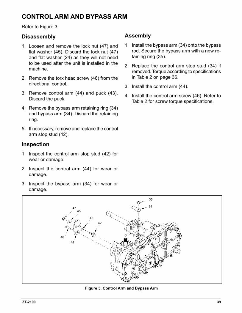
Figure 3. Control arm and Bypass arm
Refer to Figure 3.
Disassembly1. Loosen and remove the lock nut (47) and
flat washer (45). Discard the lock nut (47) and flat washer (24) as they will not need to be used after the unit is installed in the machine.
2. Remove the torx head screw (46) from the directional control.
3. Remove control arm (44) and puck (43). Discard the puck.
4. Remove the bypass arm retaining ring (34) and bypass arm (34). Discard the retaining ring.
5. If necessary, remove and replace the control arm stop stud (42).
inspection
1. Inspect the control arm stop stud (42) for wear or damage.
2. Inspect the control arm (44) for wear or damage.
3. Inspect the bypass arm (34) for wear or damage.
assembly1. Install the bypass arm (34) onto the bypass
rod. Secure the bypass arm with a new re-taining ring (35).
2. Replace the control arm stop stud (34) if removed. Torque according to specifications in Table 2 on page 36.
3. Install the control arm (44).
4. Install the control arm screw (46). Refer to Table 2 for screw torque specifications.
CONTROL aRM aND BYpaSS aRM
35
34
43
4745
42
4644
40 ZT-2100
Figure 4. Seal Kit Replacement
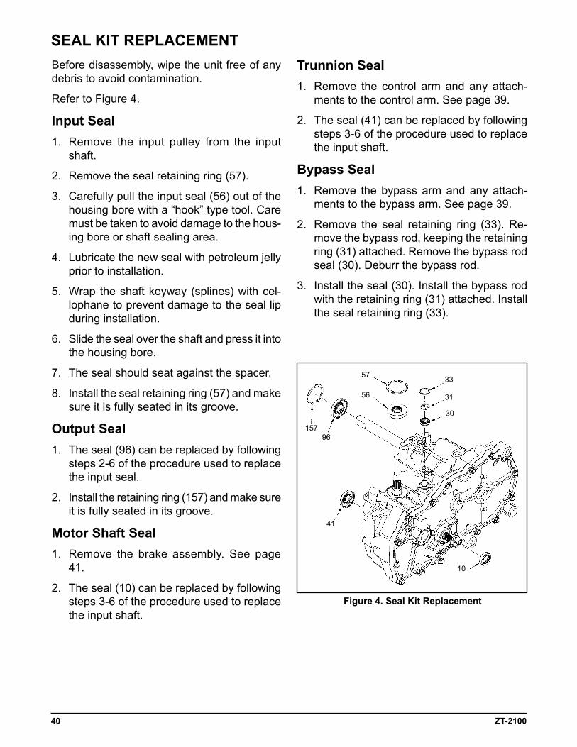
Before disassembly, wipe the unit free of any debris to avoid contamination.
Refer to Figure 4.
input Seal1. Remove the input pulley from the input
shaft.
2. Remove the seal retaining ring (57).
3. Carefully pull the input seal (56) out of the housing bore with a “hook” type tool. Care must be taken to avoid damage to the hous-ing bore or shaft sealing area.
4. Lubricate the new seal with petroleum jelly prior to installation.
5. Wrap the shaft keyway (splines) with cel-lophane to prevent damage to the seal lip during installation.
6. Slide the seal over the shaft and press it into the housing bore.
7. The seal should seat against the spacer.
8. Install the seal retaining ring (57) and make sure it is fully seated in its groove.
Output Seal1. The seal (96) can be replaced by following
steps 2-6 of the procedure used to replace the input seal.
2. Install the retaining ring (157) and make sure it is fully seated in its groove.
Motor Shaft Seal1. Remove the brake assembly. See page
41.
2. The seal (10) can be replaced by following steps 3-6 of the procedure used to replace the input shaft.
Trunnion Seal1. Remove the control arm and any attach-
ments to the control arm. See page 39.
2. The seal (41) can be replaced by following steps 3-6 of the procedure used to replace the input shaft.
Bypass Seal1. Remove the bypass arm and any attach-
ments to the bypass arm. See page 39.
2. Remove the seal retaining ring (33). Re-move the bypass rod, keeping the retaining ring (31) attached. Remove the bypass rod seal (30). Deburr the bypass rod.
3. Install the seal (30). Install the bypass rod with the retaining ring (31) attached. Install the seal retaining ring (33).
SeaL KiT RepLaCeMeNT
33
31
30
57
56
15796
41
10
ZT-2100 41
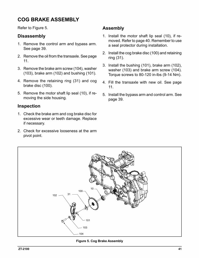
Refer to Figure 5.
Disassembly1. Remove the control arm and bypass arm.
See page 39.
2. Remove the oil from the transaxle. See page 11.
3. Remove the brake arm screw (104), washer (103), brake arm (102) and bushing (101).
4. Remove the retaining ring (31) and cog brake disc (100).
5. Remove the motor shaft lip seal (10), if re-moving the side housing.
inspection1. Check the brake arm and cog brake disc for
excessive wear or teeth damage. Replace if necessary.
2. Check for excessive looseness at the arm pivot point.
Figure 5. Cog Brake assembly
assembly1. Install the motor shaft lip seal (10), if re-
moved. Refer to page 40. Remember to use a seal protector during installation.
2. Install the cog brake disc (100) and retaining ring (31).
3. Install the bushing (101), brake arm (102), washer (103) and brake arm screw (104). Torque screws to 80-120 in-lbs (9-14 Nm).
4. Fill the transaxle with new oil. See page 11.
5. Install the bypass arm and control arm. See page 39.
COG BRaKe aSSeMBLY
103
101
104
102 31100
10
42 ZT-2100
1
23
4
5
6
7
8
9
10
11
12
13
14
15
16
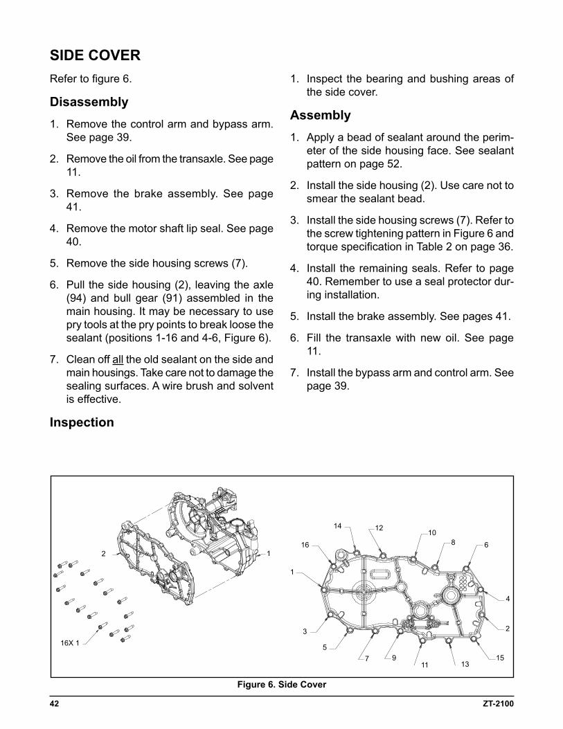
Refer to figure 6.
Disassembly1. Remove the control arm and bypass arm.
See page 39.
2. Remove the oil from the transaxle. See page 11.
3. Remove the brake assembly. See page 41.
4. Remove the motor shaft lip seal. See page 40.
5. Remove the side housing screws (7).
6. Pull the side housing (2), leaving the axle (94) and bull gear (91) assembled in the main housing. It may be necessary to use pry tools at the pry points to break loose the sealant (positions 1-16 and 4-6, Figure 6).
7. Clean off all the old sealant on the side and main housings. Take care not to damage the sealing surfaces. A wire brush and solvent is effective.
inspection
SiDe COVeR1. Inspect the bearing and bushing areas of
the side cover.
assembly1. Apply a bead of sealant around the perim-
eter of the side housing face. See sealant pattern on page 52.
2. Install the side housing (2). Use care not to smear the sealant bead.
3. Install the side housing screws (7). Refer to the screw tightening pattern in Figure 6 and torque specification in Table 2 on page 36.
4. Install the remaining seals. Refer to page 40. Remember to use a seal protector dur-ing installation.
5. Install the brake assembly. See pages 41.
6. Fill the transaxle with new oil. See page 11.
7. Install the bypass arm and control arm. See page 39.
16X 1
12
Figure 6. Side Cover
ZT-2100 43
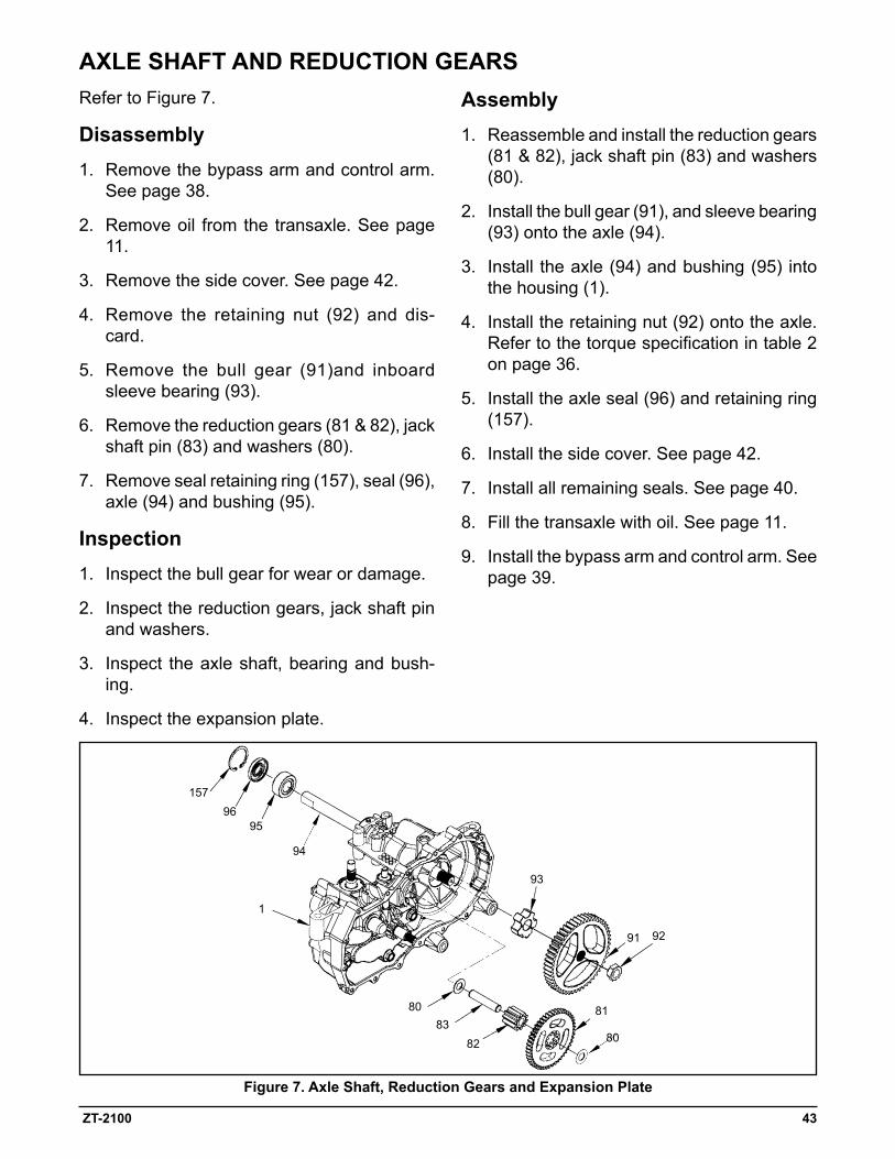
Refer to Figure 7.
Disassembly1. Remove the bypass arm and control arm.
See page 38.
2. Remove oil from the transaxle. See page 11.
3. Remove the side cover. See page 42.
4. Remove the retaining nut (92) and dis-card.
5. Remove the bull gear (91)and inboard sleeve bearing (93).
6. Remove the reduction gears (81 & 82), jack shaft pin (83) and washers (80).
7. Remove seal retaining ring (157), seal (96), axle (94) and bushing (95).
inspection1. Inspect the bull gear for wear or damage.
2. Inspect the reduction gears, jack shaft pin and washers.
3. Inspect the axle shaft, bearing and bush-ing.
4. Inspect the expansion plate.
Figure 7. axle Shaft, Reduction Gears and expansion plate
assembly1. Reassemble and install the reduction gears
(81 & 82), jack shaft pin (83) and washers (80).
2. Install the bull gear (91), and sleeve bearing (93) onto the axle (94).
3. Install the axle (94) and bushing (95) into the housing (1).
4. Install the retaining nut (92) onto the axle. Refer to the torque specification in table 2 on page 36.
5. Install the axle seal (96) and retaining ring (157).
6. Install the side cover. See page 42.
7. Install all remaining seals. See page 40.
8. Fill the transaxle with oil. See page 11.
9. Install the bypass arm and control arm. See page 39.
aXLe SHaFT aND ReDUCTiON GeaRS
15796
95
1
93
8083
82
81
80
9291
94
44 ZT-2100
Figure 8. Motor Shaft
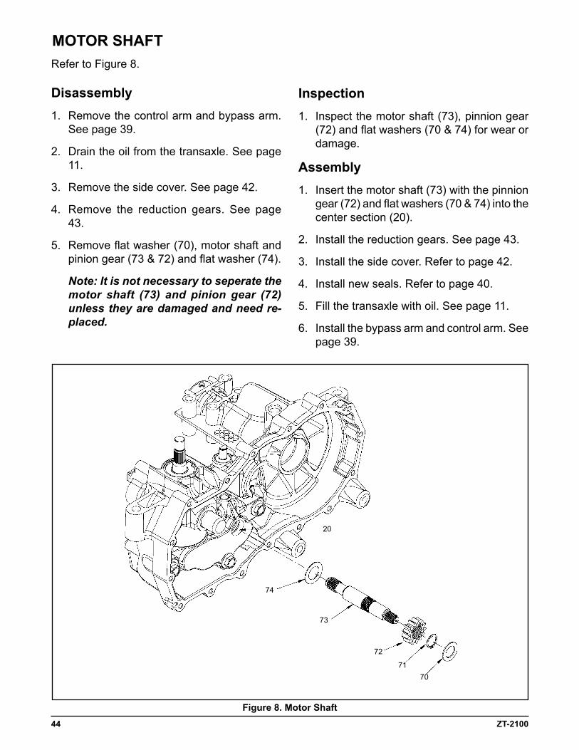
Refer to Figure 8.
Disassembly1. Remove the control arm and bypass arm.
See page 39.
2. Drain the oil from the transaxle. See page 11.
3. Remove the side cover. See page 42.
4. Remove the reduction gears. See page 43.
5. Remove flat washer (70), motor shaft and pinion gear (73 & 72) and flat washer (74).
Note:Itisnotnecessarytoseperatethemotor shaft (73) andpinion gear (72)unlesstheyaredamagedandneedre-placed.
inspection1. Inspect the motor shaft (73), pinnion gear
(72) and flat washers (70 & 74) for wear or damage.
assembly1. Insert the motor shaft (73) with the pinnion
gear (72) and flat washers (70 & 74) into the center section (20).
2. Install the reduction gears. See page 43.
3. Install the side cover. Refer to page 42.
4. Install new seals. Refer to page 40.
5. Fill the transaxle with oil. See page 11.
6. Install the bypass arm and control arm. See page 39.
MOTOR SHaFT
74
73
72
7170
20
ZT-2100 45
Figure 9. input Shaft and Bypass Rod assembly
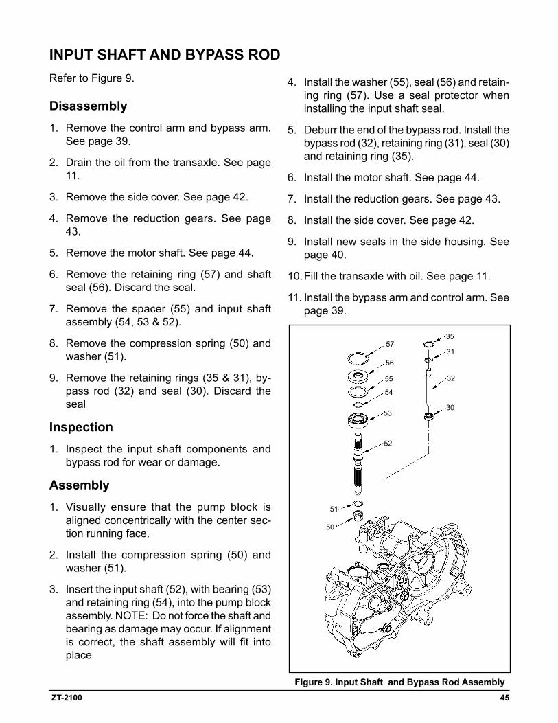
Refer to Figure 9.
Disassembly1. Remove the control arm and bypass arm.
See page 39.
2. Drain the oil from the transaxle. See page 11.
3. Remove the side cover. See page 42.
4. Remove the reduction gears. See page 43.
5. Remove the motor shaft. See page 44.
6. Remove the retaining ring (57) and shaft seal (56). Discard the seal.
7. Remove the spacer (55) and input shaft assembly (54, 53 & 52).
8. Remove the compression spring (50) and washer (51).
9. Remove the retaining rings (35 & 31), by-pass rod (32) and seal (30). Discard the seal
inspection1. Inspect the input shaft components and
bypass rod for wear or damage.
assembly1. Visually ensure that the pump block is
aligned concentrically with the center sec-tion running face.
2. Install the compression spring (50) and washer (51).
3. Insert the input shaft (52), with bearing (53) and retaining ring (54), into the pump block assembly. NOTE: Do not force the shaft and bearing as damage may occur. If alignment is correct, the shaft assembly will fit into place
4. Install the washer (55), seal (56) and retain-ing ring (57). Use a seal protector when installing the input shaft seal.
5. Deburr the end of the bypass rod. Install the bypass rod (32), retaining ring (31), seal (30) and retaining ring (35).
6. Install the motor shaft. See page 44.
7. Install the reduction gears. See page 43.
8. Install the side cover. See page 42.
9. Install new seals in the side housing. See page 40.
10. Fill the transaxle with oil. See page 11.
11. Install the bypass arm and control arm. See page 39.
iNpUT SHaFT aND BYpaSS ROD
57
56
55
54
53
52
51
50
35
31
32
30
46 ZT-2100
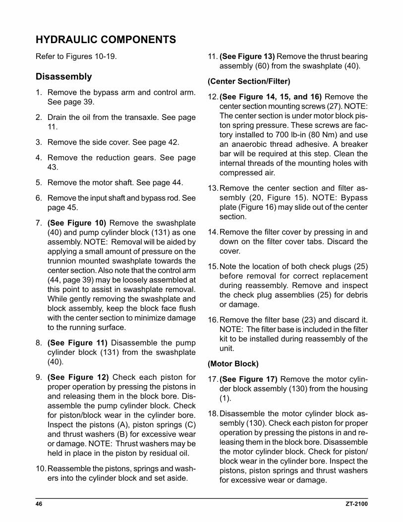
Refer to Figures 10-19.
Disassembly1. Remove the bypass arm and control arm.
See page 39.
2. Drain the oil from the transaxle. See page 11.
3. Remove the side cover. See page 42.
4. Remove the reduction gears. See page 43.
5. Remove the motor shaft. See page 44.
6. Remove the input shaft and bypass rod. See page 45.
7. (See Figure 10) Remove the swashplate (40) and pump cylinder block (131) as one assembly. NOTE: Removal will be aided by applying a small amount of pressure on the trunnion mounted swashplate towards the center section. Also note that the control arm (44, page 39) may be loosely assembled at this point to assist in swashplate removal. While gently removing the swashplate and block assembly, keep the block face flush with the center section to minimize damage to the running surface.
8. (See Figure 11) Disassemble the pump cylinder block (131) from the swashplate (40).
9. (See Figure 12) Check each piston for proper operation by pressing the pistons in and releasing them in the block bore. Dis-assemble the pump cylinder block. Check for piston/block wear in the cylinder bore. Inspect the pistons (A), piston springs (C) and thrust washers (B) for excessive wear or damage. NOTE: Thrust washers may be held in place in the piston by residual oil.
10. Reassemble the pistons, springs and wash-ers into the cylinder block and set aside.
11. (See Figure 13) Remove the thrust bearing assembly (60) from the swashplate (40).
(Center Section/Filter)
12. (See Figure 14, 15, and 16) Remove the center section mounting screws (27). NOTE: The center section is under motor block pis-ton spring pressure. These screws are fac-tory installed to 700 lb-in (80 Nm) and use an anaerobic thread adhesive. A breaker bar will be required at this step. Clean the internal threads of the mounting holes with compressed air.
13. Remove the center section and filter as-sembly (20, Figure 15). NOTE: Bypass plate (Figure 16) may slide out of the center section.
14. Remove the filter cover by pressing in and down on the filter cover tabs. Discard the cover.
15. Note the location of both check plugs (25) before removal for correct replacement during reassembly. Remove and inspect the check plug assemblies (25) for debris or damage.
16. Remove the filter base (23) and discard it. NOTE: The filter base is included in the filter kit to be installed during reassembly of the unit.
(Motor Block)
17. (See Figure 17) Remove the motor cylin-der block assembly (130) from the housing (1).
18. Disassemble the motor cylinder block as-sembly (130). Check each piston for proper operation by pressing the pistons in and re-leasing them in the block bore. Disassemble the motor cylinder block. Check for piston/block wear in the cylinder bore. Inspect the pistons, piston springs and thrust washers for excessive wear or damage.
HYDRaULiC COMpONeNTS
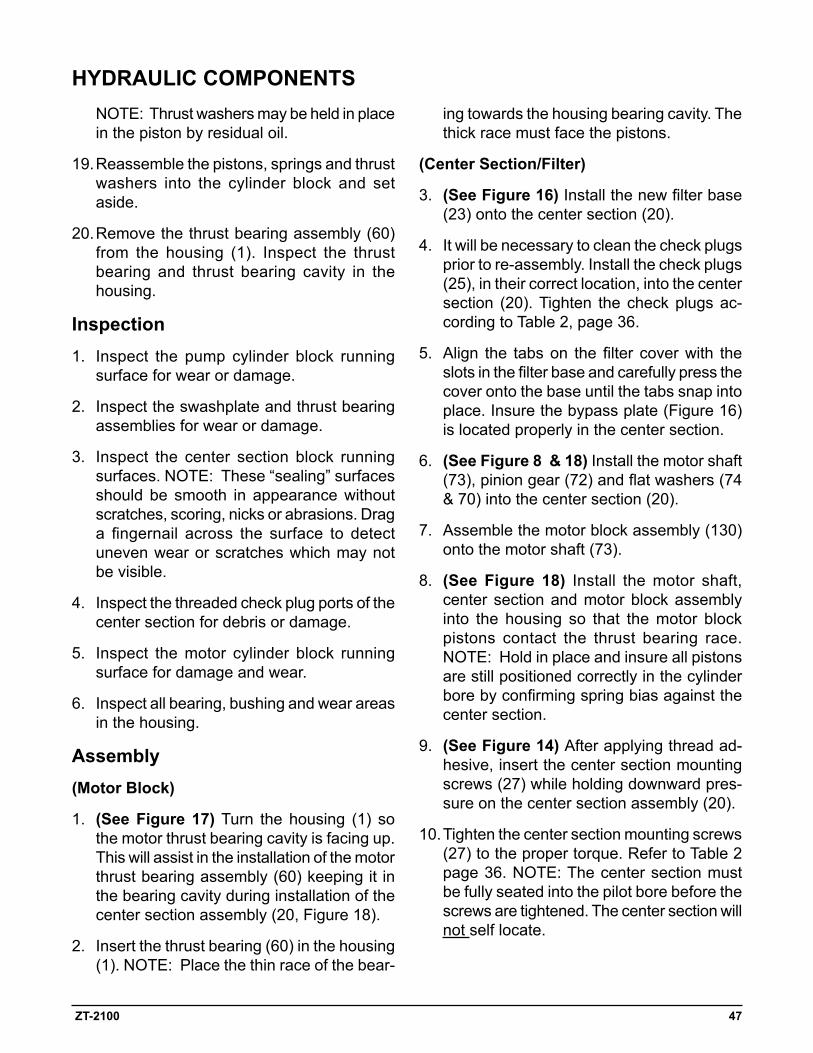
ZT-2100 47
NOTE: Thrust washers may be held in place
in the piston by residual oil.
19. Reassemble the pistons, springs and thrust washers into the cylinder block and set aside.
20. Remove the thrust bearing assembly (60) from the housing (1). Inspect the thrust bearing and thrust bearing cavity in the housing.
inspection1. Inspect the pump cylinder block running
surface for wear or damage.
2. Inspect the swashplate and thrust bearing assemblies for wear or damage.
3. Inspect the center section block running surfaces. NOTE: These “sealing” surfaces should be smooth in appearance without scratches, scoring, nicks or abrasions. Drag a fingernail across the surface to detect uneven wear or scratches which may not be visible.
4. Inspect the threaded check plug ports of the center section for debris or damage.
5. Inspect the motor cylinder block running surface for damage and wear.
6. Inspect all bearing, bushing and wear areas in the housing.
assembly(Motor Block)
1. (See Figure 17) Turn the housing (1) so the motor thrust bearing cavity is facing up. This will assist in the installation of the motor thrust bearing assembly (60) keeping it in the bearing cavity during installation of the center section assembly (20, Figure 18).
2. Insert the thrust bearing (60) in the housing (1). NOTE: Place the thin race of the bear-
ing towards the housing bearing cavity. The thick race must face the pistons.
(Center Section/Filter)
3. (See Figure 16) Install the new filter base (23) onto the center section (20).
4. It will be necessary to clean the check plugs prior to re-assembly. Install the check plugs (25), in their correct location, into the center section (20). Tighten the check plugs ac-cording to Table 2, page 36.
5. Align the tabs on the filter cover with the slots in the filter base and carefully press the cover onto the base until the tabs snap into place. Insure the bypass plate (Figure 16) is located properly in the center section.
6. (See Figure 8 & 18) Install the motor shaft (73), pinion gear (72) and flat washers (74 & 70) into the center section (20).
7. Assemble the motor block assembly (130) onto the motor shaft (73).
8. (See Figure 18) Install the motor shaft, center section and motor block assembly into the housing so that the motor block pistons contact the thrust bearing race. NOTE: Hold in place and insure all pistons are still positioned correctly in the cylinder bore by confirming spring bias against the center section.
9. (See Figure 14) After applying thread ad-hesive, insert the center section mounting screws (27) while holding downward pres-sure on the center section assembly (20).
10. Tighten the center section mounting screws (27) to the proper torque. Refer to Table 2 page 36. NOTE: The center section must be fully seated into the pilot bore before the screws are tightened. The center section will not self locate.
HYDRaULiC COMpONeNTS
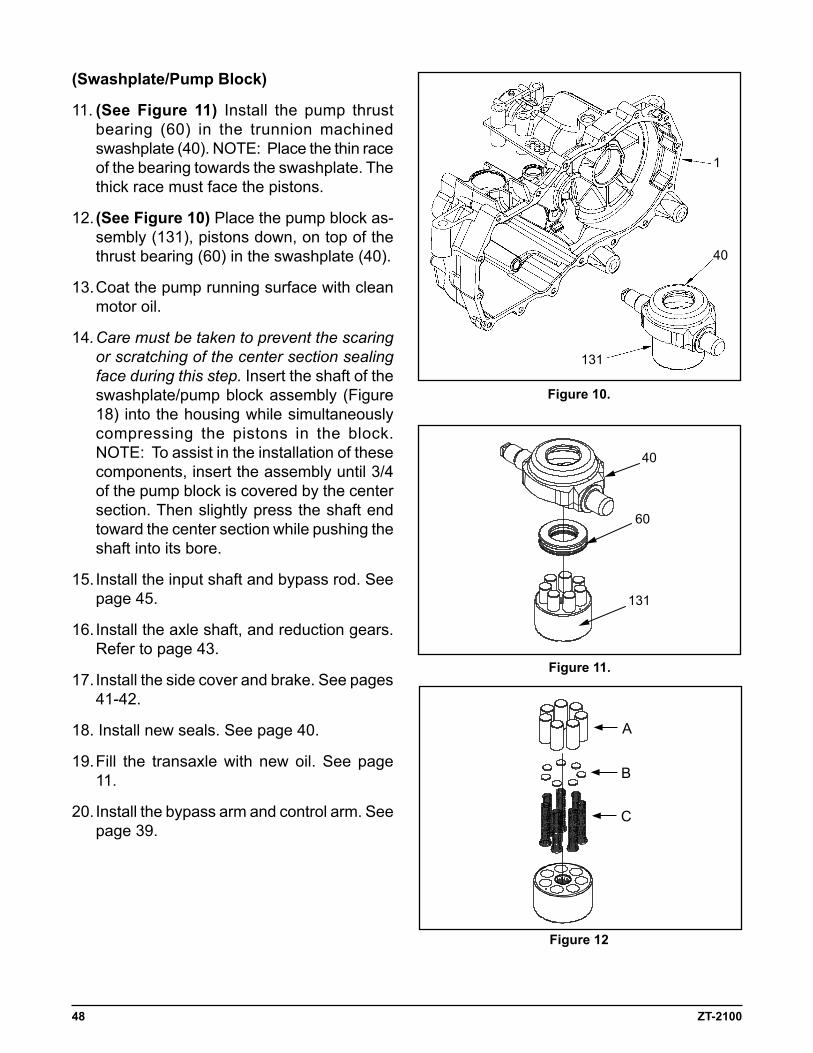
48 ZT-2100
(Swashplate/pump Block)
11. (See Figure 11) Install the pump thrust bearing (60) in the trunnion machined swashplate (40). NOTE: Place the thin race of the bearing towards the swashplate. The thick race must face the pistons.
12. (See Figure 10) Place the pump block as-sembly (131), pistons down, on top of the thrust bearing (60) in the swashplate (40).
13. Coat the pump running surface with clean motor oil.
14. Care must be taken to prevent the scaring or scratching of the center section sealing face during this step. Insert the shaft of the swashplate/pump block assembly (Figure 18) into the housing while simultaneously compressing the pistons in the block. NOTE: To assist in the installation of these components, insert the assembly until 3/4 of the pump block is covered by the center section. Then slightly press the shaft end toward the center section while pushing the shaft into its bore.
15. Install the input shaft and bypass rod. See page 45.
16. Install the axle shaft, and reduction gears. Refer to page 43.
17. Install the side cover and brake. See pages 41-42.
18. Install new seals. See page 40.
19. Fill the transaxle with new oil. See page 11.
20. Install the bypass arm and control arm. See page 39.
Figure 10.
Figure 11.
Figure 12
40
60
131
A
B
C
1
40
131
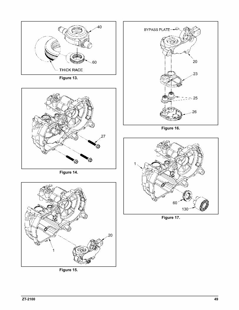
ZT-2100 49
Figure 13.
Figure 14.
Figure 15.
Figure 16.
Figure 17.
60130
1
40
60
27
20
23
25
26
20
1
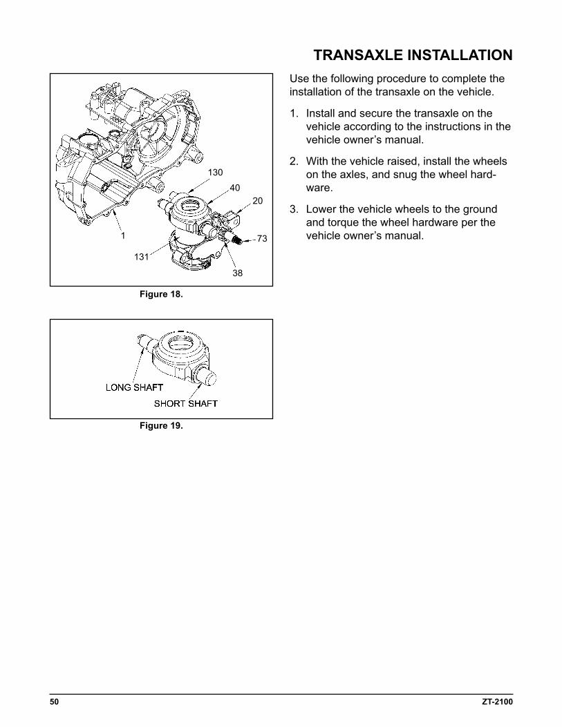
50 ZT-2100
Figure 18.
Use the following procedure to complete the installation of the transaxle on the vehicle.
1. Install and secure the transaxle on the vehicle according to the instructions in the vehicle owner’s manual.
2. With the vehicle raised, install the wheels on the axles, and snug the wheel hard-ware.
3. Lower the vehicle wheels to the ground and torque the wheel hardware per the vehicle owner’s manual.
Figure 19.
TRaNSaXLe iNSTaLLaTiON
1
131
38
73
2040
130
ZT-2100 51
If the unit has been torn down completely, the following summary identifies the assembly pro-cedures necessary to completely assemble the unit. Each assembly procedure is located by a page reference.
The part reference numbers provided in each assembly procedure are keyed to the individual exploded views, and are also keyed to the com-plete unit exploded view on page 30.
1. Install the hydraulic components. See pages 46-50.
2. Install the input shaft and bypass rod. See page 45.
3. Install the axle shaft and reduction gears. See page 43.
4. Install the cog brake and side cover. See pages 41-42.
5. Install new seals. Page 40.
5. Fill the transaxle with new oil. See page 11.
6. Install the bypass arm and control arm. See page 39.
7. Install the transaxle onto the vehicle.
8. Perform the purge procedures listed on page 12.
aSSeMBLY aFTeR a COMpLeTe TeaRDOWN
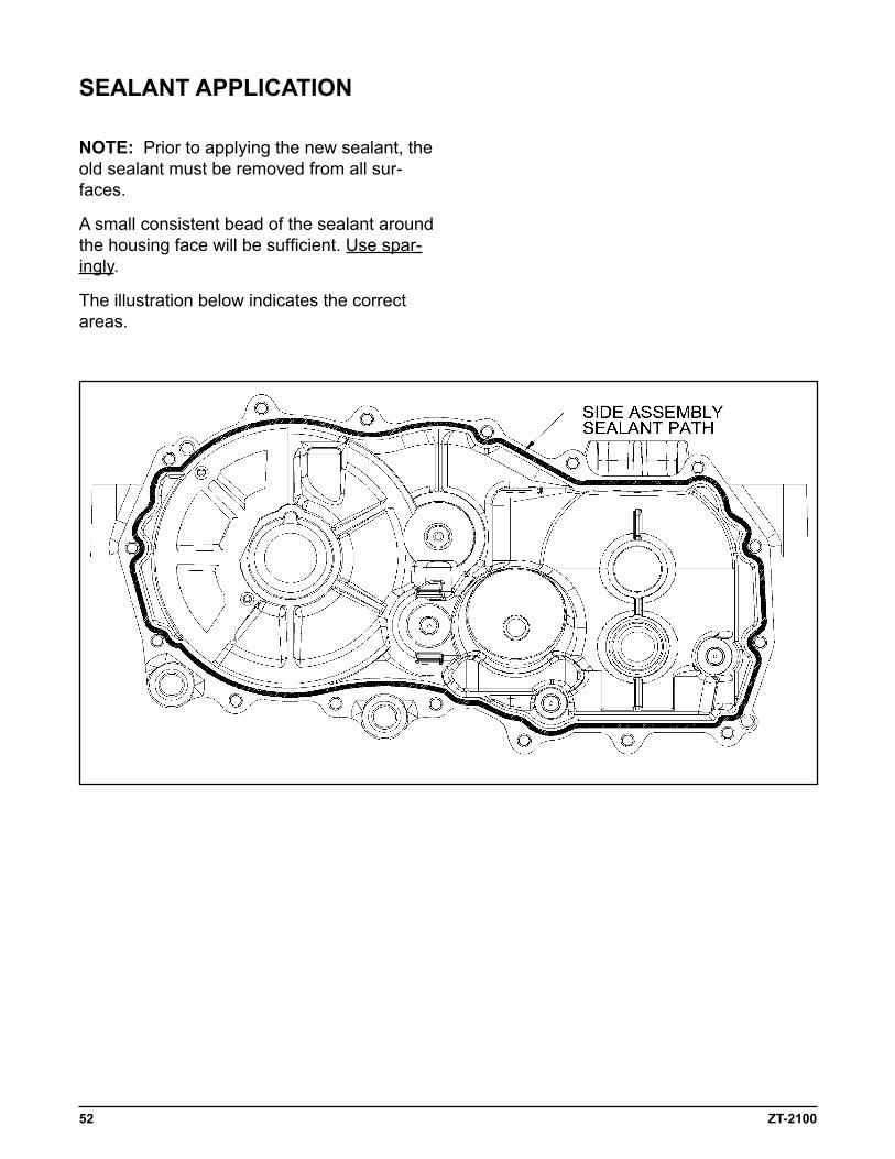
52 ZT-2100
NOTe: Prior to applying the new sealant, the old sealant must be removed from all sur-faces.
A small consistent bead of the sealant around the housing face will be sufficient. Use spar-ingly.
The illustration below indicates the correct areas.
SeaLaNT appLiCaTiON

ZT-2100 53
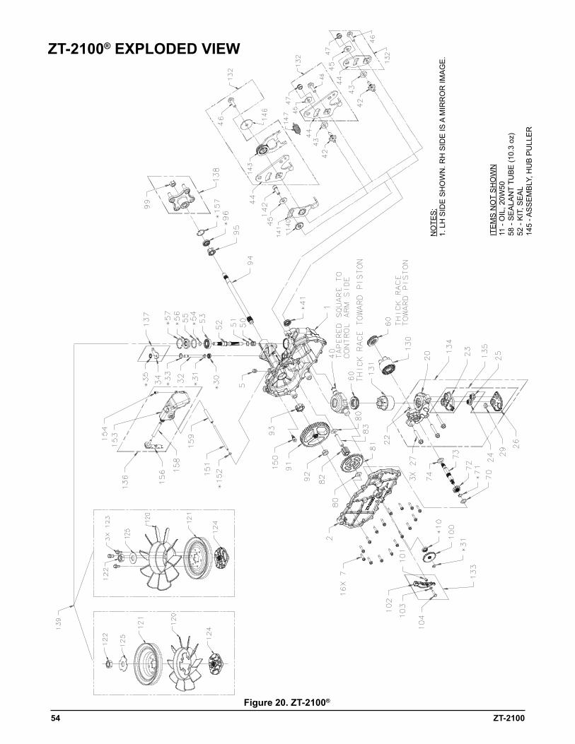
54 ZT-2100
Figure 20. ZT-2100®
ZT-2100® eXpLODeD VieW
NO
TES
: 1.
LH
SID
E S
HO
WN
. RH
SID
E IS
A M
IRR
OR
IMA
GE
.
ITE
MS
NO
T S
HO
WN
11
- O
IL, 2
0W50
58
- S
EA
LAN
T TU
BE
(10.
3 oz
) 52
- K
IT, S
EA
L 14
5 - A
SS
EM
BLY
, HU
B P
ULL
ER
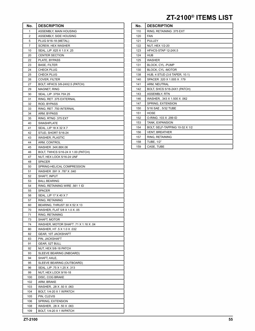
ZT-2100 55
ZT-2100® iTeMS LiSTNo. DeSCRipTiON
1 ASSEMBLY, MAIN HOUSING2 ASSEMBLY, SIDE HOUSING5 PLUG 9/16-18 (METAL)7 SCREW, HEX WASHER
10 SEAL, LIP .625 X 1.0 X .2520 CENTER SECTION22 PLATE, BYPASS23 BASE, FILTER24 CHECK PLUG25 CHECK PLUG26 COVER, FILTER27 BOLT, HFHCS 3/8-24X2.5 (PATCH)
29 MAGNET, RING
30 SEAL, LIP .375X.75X.25
31 RING, RET .375 EXTERNAL32 ROD, BYPASS33 RING, RET .750 INTERNAL34 ARM, BYPASS35 RING, RTNG .375 EXT40 SWASHPLATE41 SEAL, LIP 18 X 32 X 742 STUD, SHORT 5/16-2443 WASHER, PLASTIC44 ARM, CONTROL45 WASHER .34X.88X.0646 BOLT, TWHCS 5/16-24 X 1.00 (PATCH)47 NUT, HEX LOCK 5/16-24 UNF48 SPACER50 SPRING-HELICAL COMPRESSION51 WASHER .591 X .787 X .04052 SHAFT, INPUT53 BALL BEARING54 RING, RETAINING WIRE .561 1 ID55 SPACER56 SEAL, LIP 17 X 40 X 757 RING, RETAINING60 BEARING, THRUST 30 X 52 X 1370 WASHER, FLAT 5/8 X 1.0 X .0571 RING, RETAINING73 SHAFT, MOTOR74 WASHER, MOTOR SHAFT .71 X 1.16 X .0480 WASHER, HT .5 X 1.0 X .03282 GEAR, 10T JACKSHAFT83 PIN, JACKSHAFT91 GEAR, 52T BULL92 NUT, HEX 5/8-18 PATCH93 SLEEVE BEARING (INBOARD)94 SHAFT, AXLE,95 SLEEVE BEARING (OUTBOARD)96 SEAL, LIP .75 X 1.25 X .31399 NUT, HEX LOCK 9/16-18100 DISC, COG BRAKE102 ARM, BRAKE103 WASHER, .28 X .50 X .063104 BOLT, 1/4-20 X 1 W/PATCH105 PIN, CLEVIS106 SPRING, EXTENSION108 WASHER, .28 X .50 X .063109 BOLT, 1/4-20 X 1 W/PATCH
No. DeSCRipTiON110 RING, RETAINING .375 EXT120 FAN121 PULLEY122 NUT, HEX 1/2-20123 HFHCS-STAP 12-24X.5124 HUB125 WASHER131 BLOCK, CYL -PUMP130 BLOCK, CYL -MOTOR138 HUB, 4 STUD (3.6 TAPER, 10.1)140 SPACER .320 X 1.005 X .179141 ARM, NEUTRAL 142 BOLT, SHCS 5/16-24X1 (PATCH)143 ASSEMBLY, RTN146 WASHER, .343 X 1.500 X .062147 SPRING, EXTENSION150 5/16 SAE , 5/32 TUBE151 HOSE152 O-RING .103 X .299 ID153 TANK, EXPANSION154 BOLT, SELF-TAPPING 10-32 X 1/2156 VENT, BREATHER157 RING, RETAINING158 TUBE, 1/2”159 CASE, TUBE
56 ZT-2100
AxialPiston: Type of design for hydraulic motors and pumps in which the pistons are arranged parallel with the spindle (input or output shaft).
BantamDuty: A descriptive term relating to the product capacity (meaning: light duty).
BypassValve:A valve whose primary function is to open a path for the fluid to bypass the motor or pump. Also referred to occasionally as the freewheel valve or dump valve.
CaseDrainLine(ReturnLine): A line returning fluid from the component housing to the reser-voir.
Cavitation:A concentrated gaseous condition within the fluid causing the rapid implosion of a gaseous bubble.
CenterSection: A device which acts as the valve body and manifold of the transmission.
ChargePump: A device which supplies replenishing fluid to the fluid power system (closed loop).
ChargePressure: The pressure at which replenishing fluid is forced into a fluid power system.
ChargeReliefValve: A pressure control valve whose primary function is to limit pressure in the charge circuit.
CheckValve: A valve whose primary function is to restrict flow in one direction.
ClosedLoop: A sealed and uninterrupted circulating path for fluid flow from the pump to the motor and back.
DecayRate: The ratio of pressure decay over time.
EndCap: See “Center Section”
EntrainedAir: A mechanically generated mixture of air bubbles having a tendency to separate from the liquid phase.
Gerotor: A positive displacement pump frequently used as a charge pump.
HydraulicMotor: A device which converts hydraulic fluid power into mechanical force and mo-tion by transfer of flow under pressure.
HydraulicPump: A device which converts mechanical force and motion into hydraulic fluid power by producing flow.
HydrostaticPump: See “Hydraulic Pump”
HydrostaticTransaxle: A multicomponent assembly including a gear case and a hydrostatic transmission.
GLOSSaRY OF TeRMS
ZT-2100 57
HydrostaticTransmission: The combination of a hydraulic pump and motor in one housing to form a device for the control and transfer of power.
InletLine:A supply line to the pump.
IntegratedZero-TurnTransaxle:The combination of a hydrostatic transmission and gear case in one housing to form a complete transaxle.
Manifold:A conductor which provides multiple connection ports.
Neutral: Typically described as a condition in which fluid flow and system pressure is below that which is required to turn the output shaft of the motor.
PressureDecay: A falling pressure.
Priming:The filling of the charge circuit and closed loop of the fluid power system during start up, frequently achieved by pressurizing the fluid in the inlet line.
Purging:The act of replacing air with fluid in a fluid power system by forcing fluid into all of the components and allowing the air a path of escape.
RatedFlow: The maximum flow that the power supply system is capable of maintaining at a specific operating pressure.
Scoring:Scratches in the direction of motion of mechanical parts caused by abrasive contami-nants.
SwashPlate:A mechanical device used to control the displacement of the pump pistons in a fluid power system.
SystemChargeCheckValve: A valve controlling the replenishing flow of fluid from a charge circuit to the closed loop in a fluid power system.
SystemPressure: The pressure which overcomes the total resistance in a system, including all efficiency losses.
Valve: A device which controls fluid flow direction, pressure, or flow rate.
VariableDisplacementPump: A pump in which the displacement per revolution can be var-ied.
VolumetricDisplacement: The volume for one revolution.

58 ZT-2100
©2013 Hydro-GearPrinted in U.S.A.Rev. P11